Embed Size (px)
Citation preview

Instruction for installation, operation & maintenance
H range

Operating instructions
1. INTRODUCTION
The following operating instructions contain some information of prime importance for the installation, the functioning and the maintenance of Bedu pumps. Before setting the pump in motion and before starting any work of maintenance, it is necessary that these instructions are carefully read and well understood. 1.1 OPERATING INSTRUCTIONS
These operating instructions are connected with a peculiar pump model and with its specific application, which has been agreed in the offer by the buyer and the producer. For this reason the operating instructions have to be drawn up by Bedu technical office and reproducing this manual without producer’s approval is not allowed. A copy of these operating instructions should be kept close to the place of installation, so that it can be easily consulted whenever it is necessary. 1.2 PRODUCER
The manufacturer of the pumps is Bedu Pompen B.V.
1.3 RANGE, SIZE, YEAR OF CONSTRUCTION AND SERIAL NUMBER
Range, size, year of construction and serial number are specified on the nameplate fixed on the pump lantern and in the Declaration of Conformity attached to this manual. Nameplate data always have to match with data related in the Declaration of Conformity.
1.4 ESSENTIAL INFORMATION FOR INQUIRIES AND ORDERS
When inquiring about spare parts or placing orders, the following information is required:
Model of the pump
Year of construction and serial number of the pump.
www.bedu.eu

Operating instructions
1.5 ACOUSTIC LEVEL PRESSURE
The Acoustic Level Pressure is measured in accordance with Directive 2006/42/CE to assure that the noise level of Bedu machines does not exceed 85 dB (A). The noise emission generated by the drive and the pipes is not included in the above emission value. The pump has to be correctly mounted and not allowed to cavitate in order not to exceed the permitted acoustic level.
1.6 WARRANTY
Bedu Pompen B.V. reserves the right to revoke the warranty if:
the use of the pump is different from the operating purpose agreed in the offer;
the instructions of this manual are not respected or if they are not fully or not
correctly observed;
The pump is transformed or modified without manufacturer’s prior approval;
Works of repairing or maintenance are realized by non‐qualified personnel or
without Bedu approval;
The spare parts and the accessories are not original or not in compliance with the
specifications provided by Bedu technical office.
www.bedu.eu

Operating instructions
2. SAFETY PRECAUTIONS In order to avoid any personnel’s accident or permanent damage to the machinery, these
operating instructions have to be read and understood by the responsible for installation,
functioning and maintenance.
Indications concerning peculiar situations of danger are marked with the following safety signs:
General danger
Electric shock risk
Danger suspended load
Obligation
www.bedu.eu

Operating instructions
2.1 PERSONNEL’S QUALIFICATION AND TRAINING
Personnel responsible for the assembling, the functioning and the maintenance of Bedupumps
must be in possession of the required technical expertises to accomplish the job. Whether
personnel lacks the required skills and knowledge, it is imperative to provide an appropriate
training.
2.2 CONSEQUENCES OF NONCOMPLIANCE WITH SAFETY PRECAUTIONS
Failure to comply with safety precautions involves risks for people, for the machinery and for the
environment.
Some examples of possible consequences due to non‐compliance with safety precaution are given below:
Permanent damages to the pump and/or to the plant in which the pump is installed;
Damage or malfunctioning of the pump;
Danger for people (owing to electrical or mechanical malfunctioning or to contamination with dangerous materials);
Danger for the environment (leakage of dangerous materials).
2.3 SAFETY RULES
During the installation, the functioning and the maintenance of the pump it is required:
The compliance with the basic safety rules that are reported in these operative instructions;
The compliance with the safety rules reported in the National regulations and in the International regulations;
The compliance with the safety rules of the company in which the pump is installed.
In case of non‐compliance with the above‐written safety rules, the warranty becomes null and void.
www.bedu.eu

Operating instructions
2.4 SAFETY INSTRUCTION FOR THE ENDUSER
The external parts of the pump that are likely to reach extremely high or extremely low temperature must be provided with appropriate protective devices in order to avoid any contact with them.
The protective guards for moving parts must not be removed whilst the machine is in operation;
Leakages of hazardous liquids (e.g. explosive, toxic, hot) must be drained in conformity with the regulations in force.
The risks of exposure to electric current must be eliminated.
2.5 SAFETY INSTRUCTIONS FOR MAINTENANCE, INSPECTION AND ASSEMBLY WORK
Ensure that personnel responsible for maintenance, inspection and assembly work has read these operating instructions and has sufficient acquaintance with the pump.
Ensure that all the parts of the pump which are in contact with the pumped liquid are decontaminated;
Ensure that during the entire work of maintenance the electric current is disconnected;
Accomplished the works of maintenance, ensure that all the safety and protective devices have been replaced in their original position and, where necessary, reactivate them;
Prior reactivating the machine, fulfil the procedures for the “Start‐up and temporary shutdown” reported in chapter 6 of these operating instructions.
www.bedu.eu

Operating instructions
2.6 UNAUTHORISED USE OF SPARE PARTS AND/OR MODIFICATIONS OF THE PUMP
Transformations or modifications of the pump are permitted only with prior written approval of Bedu technical office. Original spare parts and accessories, authorised by the manufacturer, ensure personnel’s safety and the optimal performance of the pump. The use of non‐original spare parts revokes any manufacturer’s liability for malfunctioning or related damages.
2.7 HAZARDOUS MATERIALS HANDLING
The following information deals with handling of dangerous materials used inside the pumps, which might be hazardous to the health.
In the table below is reported the list of hazardous materials, their location and the possible risk for the health.
LOCATION MATERIAL DANGER FOR Bearings Anti‐seize compound Breathing
Stator, rotor Grease‐Vaseline Hands and skin Gearbox Lubricant oil Eyes and skin
Pump surface Paint Flammable material
In case of accidental contact with the above‐mentioned substances, follow these instructions:
Skin: wash with cold water and soap;
Inhalation: immediately go out and breathe fresh air;
Eyes: Rinse out with cold water and urgently go to a medical centre.
www.bedu.eu

Operating instructions
3. GENERAL DESRIPTION OF BEDU PUMP The supplied progressive cavity pump is part of the “Volumetric Pump Family”, whose inventor was professor René Moineau. The pumping system is mainly composed by:
The stator – a stationary part, usually an alloy tube containing an injected elastomer;
The rotor – a rotating part, usually made of metallic material.
The rotor has a circular cross‐sectional configuration and, rotating inside the stator, allows product pumping. The stator is formed as a double‐helix with twice the pitch of the rotor, thus the interference fit between the rotor and the stator creates a series of sealed chambers. When the rotor rotates inside the stator, the medium is gently conveyed from the inlet to the outlet of the cavities. The volume of the medium is always constant, since the flow is always continuous and not subject to any impulse. Bedu progressive cavity pump groups many peculiarities of other kinds of pump:
Like diaphragm and peristaltic pumps, Bedu pump can convey heterogeneous materials, containing gas and abrasive material, fibrous and solid substances;
Like impeller pumps, Bedu pump has no suction or pressure valves, but it has a stable flow rate in proportion to the number of revolutions;
Like piston pumps, Bedu pump has a high suction capacity;
Like gear or screw pumps, Bedu pump can handle high‐viscosity media;
Like piston, diaphragm, impeller or screw pumps, Bedu pump has a high dosage precision.
Furthermore, Bedu progressive cavity pump has the following advantages:
self‐priming even if not totally filled with liquid;
gentle handling of shear‐sensitive products;
no significant torque increase when reaching maximum performance;
no pulsation, low noise and vibration.
www.bedu.eu

Operating instructions
4. PACKING, TRANSPORTATION AND STORAGE
4.1 PACKING AND TRANSPORTATION
The personnel responsible for the transport and the storage of the pump must be acquainted with the lift and fastening equipment, in full compliance with the safety regulations.
Bedu pumps are usually shipped on skid‐mounted cardboard boxes or in wood‐framed enclosures.
Upon receipt, inspect the pump for any transportation damage. Any possible damage should be immediately reported to the freight carrier. Furthermore, upon receipt, ensure that the supplied pump matches with data reported in the Delivery Note and in your order. The pump must be carried as close as possible to the installation site and it must be unpacked only
at assembling time.
Avoid suspending the complete pump unit by the eye bolts of the motor or of the gearbox. These eye bolts should be used for lifting the motor and/or the gearbox only.
Use caution when lifting top‐heavy pumps. The centre of gravity may be above the points where the lifting gear is attached. In this case tighten the fastening to prevent tipping over.
When moving the pump or unit on wheels:
Disconnect the motor drive in order to prevent any unintended start‐up;
Move the pump unit carefully and slowly, especially where the ground is uneven;
Where necessary, secure the pump unit with additional support blocks;
Before operating the pump consider the reaction forces and the possible movements of the flexible piping at start up time.
www.bedu.eu

Operating instructions
Due to the wide range of pump models and applications, here can be given only general instructions for pump unit handling. In order to have more specific and detailed instructions address to Bedu technical office.
4.2 STORAGE
Pumps are packaged for the transportation and a short‐term storage. In case of long‐term storage the pump should be protected as follows:
STATOR: When stored for a long period, the rotor might deform permanently the geometry of the stator; for this reason it is necessary to remove the stator and store it in a cool and dry place.
ROTOR: After having the stator removed, support the rotor with wooden blocks and cover it in order to prevent any damage.
Store in a cool and dry place.
No solvents, oil, grease, lubricants or any chemicals must be kept in the store room.
Store room should be protected from damp and condensation; it must be free of dust and well ventilated.
Rubber products must be protected against light, particularly from direct sunlight or artificial light with high UV portion.
Rubber parts should be kept in sealed packages.
SUPPLIED MODEL:
STORE ROOM:
www.bedu.eu

Operating instructions
5. ASSEMBLY AND INSTALLATION
5.1 MOUNTING TOOLS
No special tools are required for the assembly and installation of the pump.
5.2 SPACE REQUIREMENTS
Customers are responsible for determining the space requirements for the installation of the pump. The following factors must be taken into account:
Dimensions and weight of the machine;
Required transportation and hosting equipment (AB)
Required space to:
Regulate the speed of the pump (in case of a pump with engine block);
Lubricate the engine block; Remove the protective devices; Handle the mounting tools; Remove the stator and the rotor
In order to evaluate the required space to remove the rotor and the stator, consider the figure below:
www.bedu.eu

Operating instructions
5.3 DIRECTION OF ROTATION
The rotational direction of the pump determines the flow direction of the conveying medium and, as a consequence, the direction of the suction and discharge flanges of the pump. The directional rotation of the drive shaft and of the rotor is given by an arrow on the nameplate of the pump. For some models the direction of rotation can be reversible; to this end check the technical data agreed in the offer or address to Bedu technical office.
Generally, for the direction of the suction flange and the discharge flange consider the figure below:
ANTICLOCKWISE (STD) CLOCKWISE
5.4 PIPING SIZE
The pipes diameters on the suction and pressure sides must be dimensioned in accordance with the flow rate calculations and with the performances of the supplied model. The nominal size of the suction pipe should at least match that of the pump suction flange. However, the calculation of the flow rate loss is essential. The right choice of the pipes is essential to guarantee the correct functioning of Bedu pump. Prior to starting up the pump, clean the pipes end ensure that all the pipelines are free from foreign bodies.
5.5 ELECTRICAL CONNECTION
The electrical connection must be established in accordance with the manufacturer’s specifications and with the safety specifications applied at the installation site. All the works concerning the electrical connections must be accomplished by qualified and
authorized personnel.
www.bedu.eu

Operating instructions
The voltage rating and the frequency of the electricity main must match with the data on the motor nameplate or on the frequency converter. The voltage rating, the frequency and the motor power are specified on the motor nameplate. Three‐phase cage motor:
Delta connection Star connection
Delta connection Star connection
Due to the friction between rotor and stator, upon the pump starting it is required an increased starting torque; for this reason, the motor unit can be connected to the electrical main directly or by a frequency converter.
Respect the following advices:
Install a circuit‐breaker on the master switch connection;
Install a working switch as close as possible to the pump;
Install an earth leakage circuit breaker.
www.bedu.eu

Operating instructions
6. START UP AND TEMPORARY SHUTDOWN
6.1 START UP
Bedu progressive Cavity Pumps must be operated observing the following precautions:
Before the first start‐up ensure that the pump housing and the suction piping are filled with medium. Priming of the pump is necessary to lubricate the stator.
Never run the pump dry. Even a few rotations in dry conditions will damage the stator.
‐
• Whether the fluid has a high level of viscosity, for the first start‐up fill the pump housing and the suction piping with flowing medium, i.e. water.
• Ensure that the suction and the discharge flanges are correctly connected.
• Start up the pump for several rotations to ensure that the direction of rotation corresponds to the direction specified on the nameplate and/or on the suction chamber.
• In the case of wrong direction, convert the motor electrical connections in order to reverse the direction.
All the pipelines of the discharge line must always be opened. Otherwise, it could occur an immediate pressure increase which could lead to the burst of the piping, to the leakage of dangerous substances and to the permanent damage of the pump. Therefore the plant in which the pump is installed must be provided with safety devices as protective measures against overpressure, e.g. pressure gauge and manometers, valves and by‐pass systems.
Before pump start‐up ensure that:
• All the valves on the pumping line are opened;
• The direction of rotation is correct.
www.bedu.eu

Operating instructions
6.2 TEMPORARY SHUTDOWN
Following the temporary shutdown, the pump should be emptied and flushed when:
The pump is installed in a location inside or outside where the medium has the potential to freeze;
The medium has the tendency to solidify or harden;
The medium is likely to build up or to become tacky on the shaft‐sealing area.
Other suggestions:
STATOR: When stored for a long period, the rotor could deform permanently the surfaces in contact with the stator; for this reason it is necessary to remove the stator and store it in a cool and dry place.
ROTOR: After having removed the stator, support the rotor with wooden blocks and cover it in order to prevent any damage.
6.3 STANDBY PUMP
A stand‐by pump is sometimes installed to eliminate downtime. Stand‐by pumps should be operated occasionally to keep them properly conditioned for use.
www.bedu.eu

Operating instructions
7. CLEANING
The use of caustic soda, citric acid and other chemically‐aggressive substances employed for the cleaning, could occasion skin burns.
Use rubber gloves throughout the cleaning process.
Use protective glasses throughout the cleaning process.
If the plant in which the pump is installed is equipped with CIP system (Cleaning in place system), the disassembly of the pump is not required. If the plant is not provided with an automatic cleaning process, disassemble the pump following the instruction of paragraph 8.4.2. 7.1 RECOMMENDATIONS FOR CLEANING IN PLACE AND SANITIZATION OF THE PUMP Systems for cleaning in place (CIP) and sanitization (SIP) were developed by the dairy industry in the 1950s with the goal of reducing cleaning times. These systems have now practically replaced manual cleaning. They can be separated or associated. 7.2 CLEANING IN PLACE C.I.P. The goals of cleaning in place are threefold:
Elimination of organic residues (sugars, proteins, fats, etc.); Elimination of mineral residues (salts, etc.); Reduction of the number of micro‐organisms.
Example of a cleaning‐in‐place procedure:
1. Rinse with cold water to eliminate deposits. 2. Alkaline detergents, e.g., caustic soda (concentration of 1~2%) at 80~85°C for about
20 minutes to eliminate organic residues; 3. Intermediate water rinse; 4. Acid detergents, e.g., HNO3 (concentration of 1~2%) at 70~75°C for about 10 minutes
to eliminate mineral residues. 5. Final rinse.
Phases (2) and (4) can be grouped together by using a reagent that combines an organic solvent and a descaling agent.
www.bedu.eu

Operating instructions
7.2 SANITIZATION IN PLACE S.I.P. – The goal of sanitization is to reduce the number of micro‐organisms to an acceptable level. This goal is achieved through heat treatment or chemically using disinfectants. Disinfectants destroy germs on contact:
Sodium hypochlorite (bleach) may attack stainless steel and results in a lingering state;
Peroxide reagents: peracetic acid, H202 (hydrogen peroxide). E.g.. P3‐oxonia® can attack elastomers.
In the case of a thermal sanitization, the pump is in contact with hot water at 95°C for 20 minutes. Steam sterilization (140°C) is currently limited for reasons of operator and installation safety. In this case, please consult us. 7.3 CLEANING AND BEDU PUMP Cleaning in place combines 4 effects: speed of solution flow (mechanical effect), temperature, chemical reagents and cleaning time. An optimized combination of these 4 effects should reduce cleaning implementation costs, e.g., if solution speed is increased, cleaning time may be reduced. 7.4 MECHANICAL EFFECT The cleaning solutions must flow with sufficient speed and turbulence so as to eliminate the debris present in the pump. CIP flow is generated by a specific centrifugal pump. The recommended speed is generally between 1.5 m/s and 2 m/s. For Bedu pumps, these speeds are often much higher than production flows. During cleaning in place, the pump continuously operates at a speed of between 100 and 200 rpm, with optimum being 100 rpm to allow good rotor‐stator lubrication and minimize constraints. The action of the rotor inside the stator results in good debris elimination. In this case, the CIP pump generates a higher flow than the Bedu pump and the excess flow bypasses the rotor‐stator assembly. For H‐series pumps, Bedu offers a body with CIP tubing placed in front of the stator inlet. This setup allows high CIP solution speeds in the body. The standard tubing available is vertical (can be oriented) or tangential (left or right). A pneumatic flap‐gate valve installed on the bypass piping closes this piping during production and opens it during cleaning in place and sanitization. To avoid any pressure surging that may damage the pump, it is recommended that the valves not be pulsed during pump operation. In the body of progressive cavity pumps, we usually accept solution velocity between 1 and 1,5 m/s (5 ft/sec).
www.bedu.eu

Operating instructions
7.5 TEMPERATURE Depending on the elastomer chosen, the Bedu stators can be used for production up to 90°C. In the case of a high‐temperature process, it is preferable to wait for the pump to cool off for 10 to 20 minutes before performing a cold‐water rinse in order to avoid stator seizure. However, during the cleaning cycle, the temperature may reach 95°C. At this temperature, rotor action does not damage the stator, provided that rotation speed is between 100 and 200 rpm, with optimum at 100 rpm for a period limited to 20 minutes. At the end of this temperature rinse, let the pump cool off for 10 to 20 minutes before starting production. Since the cleaning temperature is higher than the production temperature, motor‐drive calculations must be performed taking into account the maximum temperature. 7.6 DETERGENTS The stator and seal elastomers must be compatible with both the pumped fluid and the detergents and disinfectants at the cleaning temperature. Since these reagents are aggressive, it is imperative that the concentrations recommended by the supplier are respected.
www.bedu.eu

Operating instructions
8. MAINTENANCE
8.1 GENERAL INSTRUCTIONS
The pump should be regularly rinsed or cleaned if deposits of medium are likely to build up.
Whether you need to disassemble the pump, ensure that the pump and the motor are switched off and cannot be turned on accidentally.
8.2 LUBRICATION
Bedu pump does not need a frequent lubrication. The rotor and the stator are lubricated by the conveyed medium; for this reason progressive cavity pump cannot run dry.
Maintenance and lubrication of the drive unit should be carried out according to the drive manufacturer’s instructions.
8.3 LUBRICATION OF THE JOINT
It is recommended to change the oil in the joints in case of:
Replacement of any spare part of the joint;
Dismantling of the pump.
8.4 REMOVAL AND ASSEMBLY OF THE STATOR AND THE ROTOR
All maintenance, inspection and installation works must be performed by authorised and qualified personnel, who has understood the operating instructions and has been properly trained.
www.bedu.eu

Operating instructions
8.4.1 PREVENTIVE ACTIONS
Cut off the electricity from the drive unit and ensure that it cannot be turned on accidentally.
Empty the pump.
Let the pump cool off and ensure that it has reached room temperature. Ensure that both in the suction side and in the discharge side there is no pressure (check the manometers on the pumping line). Close all the valves of the piping.
Carefully disconnect the pipe work on the suction side and pressure side of the pump.
8.4.2 REMOVAL OF THE STATOR AND OF THE SUCTION CHAMBER
Disassembly of the stator can be made considerably easier by first moistening the inner surface of the stator with antiseize agent (soft or liquid soap). If is possible, before removing the discharge flange (050) pour the antiseize agent into the opening between rotor and stator on the discharge flange side. Several Clockwise revolutions of the rotor will then distribute the antiseize agent over the inner surface of the stator and will reduce the friction between rotor and stator considerably.
• Remove the screws from the support feet (870). • Unscrew the nuts (910) from the discharge flange (050). • Remove the discharge flange (050) and the support feet (870). • Unscrew the other nuts (910) of the tie rods and ease out the tie rods (860). • Ease out the stator (305). • Remove the protection (972) from the block lantern (005) or from the bearing housing
(015). • Remove the nuts (911) that connect the suction chamber (025) with the block lantern
(005). • Pull out the suction chamber (025) from the forepart of the pump. • Remove the o‐ring (701) between the suction chamber (025) and the block lantern (005).
www.bedu.eu

Operating instructions
8.4.3 ASSEMBLY OF THE STATOR AND OF THE SUCTION CHAMBER
• Reassemble the stator (305) and the suction chamber (025) following the instructions of paragraph 8.4.3 in reverse order.
• Build the stator by using glycerine or liquid soap as lubricant.
8.4.4 REMOVAL OF THE ROTOR AND OF THE JOINT
• Remove the stator and the suction chamber (025) following the instructions of paragraph 8.4.2.
• Place the dismantled unit – block lantern (005) or bearing housing (015), connecting rod (120) and rotor (199)‐ on a workbench with a wooden block supporting the rotor (199).
• Remove the elastic ring (775) – from left to right – and the ring cover for bell (435). • Remove the two o’rings (708) and the pin joint (403). Drain the oil into an appropriate
container. • Remove the rotor (199) from the connecting rod (120). • Remove the ring for sleeve outer (445), the sleeve (790) and the ring for sleeve inter (440).
www.bedu.eu

Operating instructions
8.4.5 ASSEMBLY OF THE ROTOR AND OF THE CONNECTING ROD
• Assemble the rotor (199) and the joint‐rotor side following the instructions of paragraph 8.4.4 in reverse order.
• Be careful in filling the joint with lubricant oil. Insert the pin joint (403) and start to fill the joint with oil, let the air flow out and seal the joint with the ring cover for bell (435) and block it with the elastic ring (775).
• Concerning the joint‐drive shaft side (101), disassemble and assemble the rotor and the joint following the instructions of paragraphs 7.4.4 and 7.4.5.
www.bedu.eu
Operating instructions
8.5 BEARING HOUSING MAINTENANCE With a bearing housing pump version, the bearings have to be periodically lubricate to obtain a long life use. In case of malfunctioning, replace the bearings.
www.bedu.eu

Operating instructions
9. TROUBLE SHOOTING Before delivery, Bedu pumps are subject to hydraulic test in respect of the technical specification set in the offer. Bedu pumps will operate trouble‐free if used in accordance with the offer and with the instructions of this manual. If operating problems will arise, use this chart as a guide in locating the problem.
Troubleshooting guide
The pu
mp do
es not start
No suction capa
bility
Low discharge outpu
t
Low discharge pressure
Discharge
outpu
t fluctua
tes
The pu
mp is noisy
The pu
mp is jammed
The drive is overloa
ded
Stator and
rotor service life is too
short
The mecha
nical seal leaks
Possible cause and remedies
x x The pump or the stator is new, too much static friction. 1) Run the pump in one direction and then in the other direction until the stator unblocks. 2) Lubricate the rotor and the stator.
x x x x The power supply is not correct. 1) Check motor nameplate data. Test voltage, phase and frequency.
x x x The discharge pressure is too high. 1) Measure actual discharge pressure and compare it with the discharge pressure set in the offer.
x x x Foreign matter or debris inside the pump. 1) Remove debris and correct any damage.
x x x x The temperature of the pumped liquid is too high, the stator swells. 1) Reduce the temperature of the liquid; if it cannot be reduced, use an undersized rotor.
x x x x The liquid contains too many solids, causing blockages. 1) Check technical specification and increase liquid‐to‐solids‐ratio.
x x x x Chemical attack on the stator. 1) Check technical specification and, if it is necessary, change the stator with a correct one.
x x x x x The liquid settles and hardens at pump shut‐down. 1) Clean and rinse out the pump after each use.
x x x Incoming air from the suction piping. 1) Check connections and, if it is necessary, increase NPHS.
x x x x Suction piping leaks. 1) Check seals and connections.
www.bedu.eu

Operating instructions
Troubleshooting guide
The pu
mp do
es not start
No suction capa
bility
Low discharge outpu
t
Low discharge pressure
Discharge
outpu
t fluctua
tes
The pu
mp is noisy
The pu
mp is jammed
The drive is overloa
ded
Stator and
rotor service life is too
short
The mecha
nical seal leaks
Possible cause and remedies
x x The pump speed is too low. 1) If the drive is variable, set a higher speed.
x x x x x Discharge pressure is too high or suction head is too high (cavitation). 1) Lower suction losses; reduce liquid temperature and install the pump at lower elevation.
x x x x x x The pump is running dry. 1) Fill the pump and provide drive protection.
x x x x The stator or the rotor is worn out. 1) Check rotor and stator. Replace the worn out parts.
x The connecting rod and/or the joints are worn out. 1) Replace the worn out pieces.
x The pump speed is too high. 1) If the drive is variable, set a lower speed.
x The viscosity is too high. 1) Measure the viscosity and compare it with the viscosity set in the offer.
x x x x x The pressure head is too high. 1) Check the pressure head with manometer. Reduce the pressure head by increasing the pressure pipe diameter or by shortening the piping.
x x The direction of rotation is not correct. 1) Reverse polarity of drive motor.
x x The mechanical seal is worn or damaged. 1) Replace the mechanical seal.
x x Pump bearings are worn (bearing housing version). 1) Replace bearings and lubricate seals.
www.bedu.eu
Operating instructions
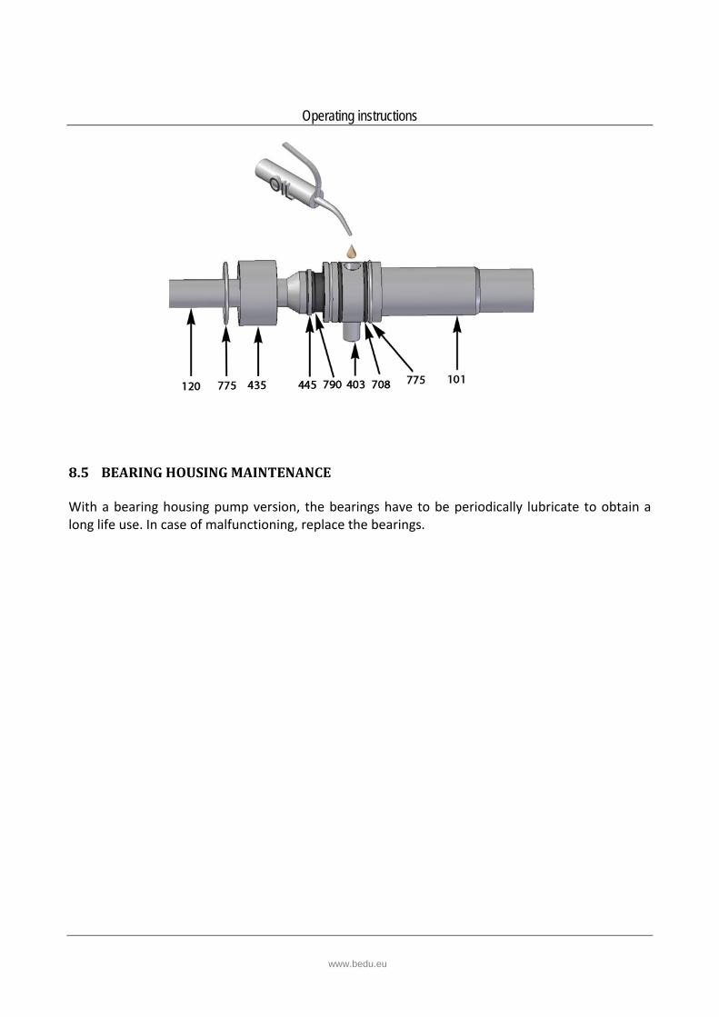
10. RECOMMENDED SPARE PARTS In general, Bedu has all the spare parts subject to wear in stock.
Our subsidiaries and exclusive representatives also hold a certain stock. It is recommended to keep an amount of spare parts corresponding to the pump in stock on site as follows .
Description
Small set
Large set
Position code
Rotor 1 199
Stator 1 1 305
Connecting rod (complete) 1 (120‐401‐912‐708‐790‐951‐403‐447‐717‐435‐415)
Mechanical seal 1 501
Lantern o’ring 1 1 701
To ensure a quick delivery, please provide the following information with your order:
Specify the model number of your pump, the serial number and the year of construction (see the nameplate on the pump);
Identify the part code you require – as per the parts drawing.
www.bedu.eu

EC – Declaration of Conformity
Manufacturer Details
TradenameBedu Pompen BV
Address
Poort van Midden Gelderland Rood 10, 6666 LT, Heteren, Netherlands
Product DetailsProduct Name
Excentric screw pumps
Model (+series) Name
Applicable Standards Details
2006/42/EC (Machinery Directive)2014/35/EU (Low Voltage Directive)2014/30/EU (Electromagnetic compatibility)
Standards
EN-ISO 12100:2010EN-IEC 60204-1:2006EN 809+A1/C1
Additional information
No further details.
Declaration
We hereby declare under our sole responsibilitythat the product(s) mentioned above to which thisdeclaration relates complies with the abovementioned standards and Directives.
BEDU Pompen BVPoort van Midden Gelderland Rood 106666 LT HeterenTel : +31 (0)88 – 4802 900Fax : +31 (0)88 – 4802 901E-mail : [email protected] : www.bedu.eu
Name Director(s): Issued Date:
01/10/ 2014
Marco Breunissen Ron Bijen
Signature of representative(s)
Directives
H
www.bedu.eu

Deskundig advies
Een klantgerichte organisatie die zich aanpast aan de eisen en wensen van uw organisatie
Innovatieve en maatwerkoplossingen
Storingsdienst 24 uur per dag, 7 dagen in de week
Technische dienst met uitgebreide testfaciliteiten, werkend vanuit onze eigen werkplaats of bij u op locatie
Een snelle en passende oplossing voor al uw vraagstukken
Breed assortiment vloeistofpompen
Reparatie, onderhoud en revisie
made for your process
BEDU POMPEN B.V.
Poort van Midden Gelderland Rood 10
6666 LT HETEREN
Nederland
Telefoon +31 (0)88 4802 900
Fax +31 (0)88 4802 901
E-mail [email protected]
WWW.BEDU.NL
BEDU BELGIUM B.V.B.A.
Industriepark-West 75 bus 24
9100 SINT-NIKLAAS
België
Telefoon +32 (0)3 80 87 980
Fax +32 (0)3 80 87 981
E-mail [email protected]
WWW.BEDU.BE