Embed Size (px)
Citation preview
VLT® 5000
MG
51C522
VLT ®
5000In
structio
nM
anu
al
Instruction Manual

Contents
Safety 4
Safety regulations 5
Warning against unintended start 5
Installation of mechanical brake 5
Technical data 6
General technical data 6
Electrical data 13
Fuses 33
Dimensions 41
Mechanical dimensions 41
Installation 44
Mechanical installation 44
Electrical installation - mains supply 58
Safety grounding 58
Extra protection (RCD) 58
RFI switch 58
Installation of motor cables 62
Connection of motor 62
Direction of motor rotation 62
Electrical installation - brake cable 63
Electrical installation - relay outputs 63
Electrical installation - 24 Volt external DC supply 63
Electrical installation - load sharing 63
Electrical installation - brake resistor temperature switch 64
Electrical installation - bus connection 64
Installation of control cables 65
Connection examples 68
Operation of the VLT 71
Control panel (LCP) 71
Control panel - display 71
Control panel - LEDs 72
Control panel - control keys 72
Quick Setup 75
Parameter selection 75
Menu mode 75
Manual initialization 77
Programming 79
Operation & Display 79
VLT® 5000 Series
MG.51.C5.22 - VLT is a registered Danfoss trademark. 1
Load and motor 87
References and limits 100
Parameters - Inputs and outputs 109
Special functions 125
Parameters - Serial communication 141
Parameters - Technical functions and diagnostics 149
Messages 156
Trouble-shooting 156
Display - Status messages 157
Warnings and alarms 160
Warnings 161
Examples of use 168
Conveyor belt 168
Pump 169
Gantry Crane 170
Torque control, speed feedback 171
VLT 5000 controllers 172
PID for process control 174
PID for speed control 175
PID for torque controller (open loop) 176
EC/EMC 177
CE labelling 177
Electrical Installation 181
Electrical installation - EMC precautions 181
Electrical installation, selection of EMC-correct cables 184
List of functions 185
Setting of parameters 185
Local and remote control 188
Control with brake function 189
References - single references 190
References - multi-references 192
Automatic Motor Adaptation, AMA 196
Mechanical brake control 198
PID for process control 200
PID for speed control 201
Quick discharge 202
Flying start 204
Normal/high overload torque control,open loop 206
Programming of Torque limit and stop 206
Galvanic Isolation (PELV) 207
Extreme Running Conditions 209
VLT® 5000 Series
2 MG.51.C5.22 - VLT is a registered Danfoss trademark.
Peak voltage on motor 210
Switching on the input 211
Motor thermal protection 215
Vibration and Shock 215
Air Humidity 215
Aggressive environments 216
Efficiency 217
Interference, Power factor 219
Parameters 220
Miscellaneous 229
Index 232
VLT® 5000 Series
MG.51.C5.22 - VLT is a registered Danfoss trademark. 3
VLT 5000 SeriesInstruction Manual
Software version: 3.9x
This Instruction Manual can be used for all VLT 5000 Series adjustable frequency drives with software version3.9x.The software version number can be seen from parameter 624.CE and C-tick labeling do not cover VLT 5001-5062, 525-600 V units.
The VLT Adjustable Frequency Drive con-tains dangerous voltages when connec-ted to line voltage. After disconnectingfrom the line wait at least 15 minutes be-fore touching any electrical components.Also make sure that other voltage inputshave been disconnected, such as external24 VDC, load-sharing (linkage of DC in-termediate circuit), as well as the motorconnection for kinetic back-up. Only acompetent electrician should carry out theelectrical installation. Improper installa-tion of the motor or the VLT may causeequipment failure, serious injury or death.Follow this manual and National ElectricalCodes (NEC®) and local safety codes.
NOTEElectrostatic Precaution; Electrostatic dis-charge (ESD). Many electronic compo-nents are sensitive to static electricity.Voltages so low that they cannot be felt,seen or heard, can reduce the life, affectperformance, or completely destroy sen-sitive electronic components. When per-forming service, proper ESD equipmentshould be used to prevent possible dam-age from occurring.
It is the responsibility of the user or theperson installing the VLT to provide prop-er grounding, as well as motor overloadand branch circuit protection according tothe National Electrical Code (NEC®) andlocal codes.
By altitudes above 2000 m, please contactDanfoss Drives regarding PELV.
VLT® 5000 Series
4 MG.51.C5.22 - VLT is a registered Danfoss trademark.
Safety regulations
1. The frequency converter must be disconnec-ted from mains if repair work is to be carriedout. Check that the mains supply has beendisconnected and that the necessary timehas passed before removing motor andmains plugs.
2. The [STOP/RESET] key on the control panelof the frequency converter does not discon-nect the equipment from mains and is thusnot to be used as a safety switch.
3. Correct protective earthing of the equipmentmust be established, the user must be pro-tected against supply voltage, and the motormust be protected against overload in ac-cordance with applicable national and localregulations.
4. The earth leakage currents are higher than3.5 mA.
5. Protection against motor overload is not in-cluded in the factory setting. If this function isdesired, set parameter 128 to data value ETRtrip or data value ETR warning.Note: The function is initialised at 1.16 x ratedmotor current and rated motor frequency. Forthe North American market: The ETR func-tions provide class 20 motor overload pro-tection in accordance with NEC.
6. Do not remove the plugs for the motor andmain supply while the frequency converter isconnected to mains. Check that the mainssupply has been disconnected and that thenecessary time has expired before removingmotor and mains plugs.
7. Please note that the frequency converter hasmore voltage inputs than L1, L2 and L3, whenloadsharing (linking of DC intermediate cir-cuit) and external 24 V DC have been instal-led. Check that all voltage inputs have beendisconnected and that the necessary timehas passed before repair work is com-menced.
Warning against unintended start
1. The motor can be brought to a stop by meansof digital commands, bus commands, refer-ences or a local stop, while the adjustablefrequency drive is connected to the AC line.These stop functions are NOT sufficient toensure that no unintended start occures andshould NOT be used for personal safety con-siderations.
2. While parameters are being changed, themotor may start. Consequently, the stop key"Stop/Reset" must always be activated, fol-lowing which data can be modified.
3. A motor that has been stopped may start iffaults occur in the electronics of the adjusta-ble frequency drive, or if a temporary over-load or a fault in the AC line supply or themotor connection ceases.
Installation of mechanical brake
Do not connect a mechanical brake to the output fromthe frequency converter before the relevant parame-ters for brake control are parameterised.
(Selection of output in parameter 319, 321, 323 or 326and cut-in current and frequency in parameter 223 and225).
Use on isolated AC line
See section RFI Switch regarding use on isolated ACline.
It is important to follow the recommendations regard-ing installation on IT line, since sufficient protection ofthe complete installation must be observed. Not takingcare using relevant monitoring devices for IT line sup-ply may result in damage.
VLT® 5000 Series
MG.51.C5.22 - VLT is a registered Danfoss trademark. 5
Saf
ety
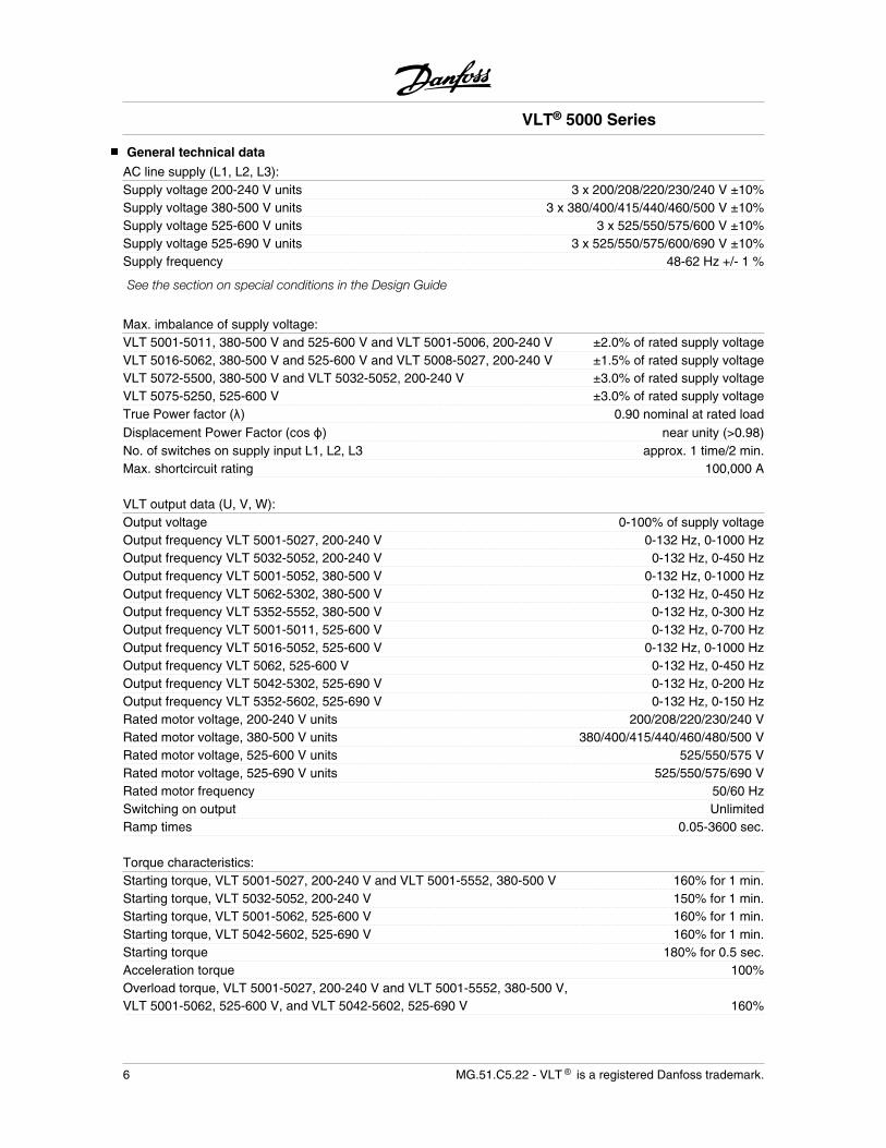
General technical data
AC line supply (L1, L2, L3):Supply voltage 200-240 V units 3 x 200/208/220/230/240 V ±10%Supply voltage 380-500 V units 3 x 380/400/415/440/460/500 V ±10%Supply voltage 525-600 V units 3 x 525/550/575/600 V ±10%Supply voltage 525-690 V units 3 x 525/550/575/600/690 V ±10%Supply frequency 48-62 Hz +/- 1 %
See the section on special conditions in the Design Guide
Max. imbalance of supply voltage:VLT 5001-5011, 380-500 V and 525-600 V and VLT 5001-5006, 200-240 V ±2.0% of rated supply voltageVLT 5016-5062, 380-500 V and 525-600 V and VLT 5008-5027, 200-240 V ±1.5% of rated supply voltageVLT 5072-5500, 380-500 V and VLT 5032-5052, 200-240 V ±3.0% of rated supply voltageVLT 5075-5250, 525-600 V ±3.0% of rated supply voltageTrue Power factor ( ) 0.90 nominal at rated loadDisplacement Power Factor (cos ) near unity (>0.98)No. of switches on supply input L1, L2, L3 approx. 1 time/2 min.Max. shortcircuit rating 100,000 A
VLT output data (U, V, W):Output voltage 0-100% of supply voltageOutput frequency VLT 5001-5027, 200-240 V 0-132 Hz, 0-1000 HzOutput frequency VLT 5032-5052, 200-240 V 0-132 Hz, 0-450 HzOutput frequency VLT 5001-5052, 380-500 V 0-132 Hz, 0-1000 HzOutput frequency VLT 5062-5302, 380-500 V 0-132 Hz, 0-450 HzOutput frequency VLT 5352-5552, 380-500 V 0-132 Hz, 0-300 HzOutput frequency VLT 5001-5011, 525-600 V 0-132 Hz, 0-700 HzOutput frequency VLT 5016-5052, 525-600 V 0-132 Hz, 0-1000 HzOutput frequency VLT 5062, 525-600 V 0-132 Hz, 0-450 HzOutput frequency VLT 5042-5302, 525-690 V 0-132 Hz, 0-200 HzOutput frequency VLT 5352-5602, 525-690 V 0-132 Hz, 0-150 HzRated motor voltage, 200-240 V units 200/208/220/230/240 VRated motor voltage, 380-500 V units 380/400/415/440/460/480/500 VRated motor voltage, 525-600 V units 525/550/575 VRated motor voltage, 525-690 V units 525/550/575/690 VRated motor frequency 50/60 HzSwitching on output UnlimitedRamp times 0.05-3600 sec.
Torque characteristics:Starting torque, VLT 5001-5027, 200-240 V and VLT 5001-5552, 380-500 V 160% for 1 min.Starting torque, VLT 5032-5052, 200-240 V 150% for 1 min.Starting torque, VLT 5001-5062, 525-600 V 160% for 1 min.Starting torque, VLT 5042-5602, 525-690 V 160% for 1 min.Starting torque 180% for 0.5 sec.Acceleration torque 100%Overload torque, VLT 5001-5027, 200-240 V and VLT 5001-5552, 380-500 V,VLT 5001-5062, 525-600 V, and VLT 5042-5602, 525-690 V 160%
VLT® 5000 Series
6 MG.51.C5.22 - VLT is a registered Danfoss trademark.
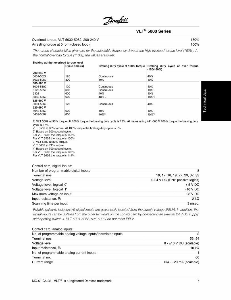
Overload torque, VLT 5032-5052, 200-240 V 150%Arresting torque at 0 rpm (closed loop) 100%
The torque characteristics given are for the adjustable frequency drive at the high overload torque level (160%). Atthe normal overload torque (110%), the values are lower.
Braking at high overload torque levelCycle time (s) Braking duty cycle at 100% torque Braking duty cycle at over torque
(150/160%)200-240 V5001-5027 120 Continuous 40%5032-5052 300 10% 10%380-500 V5001-5102 120 Continuous 40%5122-5252 600 Continuous 10%5302 600 40% 10%5352-5552 600 40%1) 10%2)
525-600 V5001-5062 120 Continuous 40%525-690 V5042-5352 600 40% 10%5402-5602 600 40%3) 10%4)
1) VLT 5502 at 90% torque. At 100% torque the braking duty cycle is 13%. At mains rating 441-500 V 100% torque the braking dutycycle is 17%.VLT 5552 at 80% torque. At 100% torque the braking duty cycle is 8%.2) Based on 300 second cycle:For VLT 5502 the torque is 145%.For VLT 5552 the torque is 130%.3) VLT 5502 at 80% torque.VLT 5602 at 71% torque.4) Based on 300 second cycle.For VLT 5502 the torque is 128%.For VLT 5602 the torque is 114%.
Control card, digital inputs:Number of programmable digital inputs 8Terminal nos. 16, 17, 18, 19, 27, 29, 32, 33Voltage level 0-24 V DC (PNP positive logics)Voltage level, logical '0' < 5 V DCVoltage level, logical '1' >10 V DCMaximum voltage on input 28 V DCInput resistance, Ri 2 kScanning time per input 3 msec.
Reliable galvanic isolation: All digital inputs are galvanically isolated from the supply voltage (PELV). In addition, thedigital inputs can be isolated from the other terminals on the control card by connecting an external 24 V DC supplyand opening switch 4. VLT 5001-5062, 525-600 V do not meet PELV.
Control card, analog inputs:No. of programmable analog voltage inputs/thermistor inputs 2Terminal nos. 53, 54Voltage level 0 - ±10 V DC (scalable)Input resistance, Ri 10 kNo. of programmable analog current inputs 1Terminal no. 60Current range 0/4 - ±20 mA (scalable)
VLT® 5000 Series
MG.51.C5.22 - VLT is a registered Danfoss trademark. 7
Tec
hnic
al d
ata
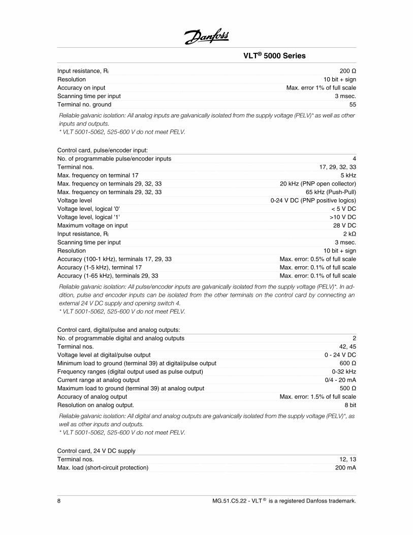
Input resistance, Ri 200Resolution 10 bit + signAccuracy on input Max. error 1% of full scaleScanning time per input 3 msec.Terminal no. ground 55
Reliable galvanic isolation: All analog inputs are galvanically isolated from the supply voltage (PELV)* as well as otherinputs and outputs.* VLT 5001-5062, 525-600 V do not meet PELV.
Control card, pulse/encoder input:No. of programmable pulse/encoder inputs 4Terminal nos. 17, 29, 32, 33Max. frequency on terminal 17 5 kHzMax. frequency on terminals 29, 32, 33 20 kHz (PNP open collector)Max. frequency on terminals 29, 32, 33 65 kHz (Push-Pull)Voltage level 0-24 V DC (PNP positive logics)Voltage level, logical '0' < 5 V DCVoltage level, logical '1' >10 V DCMaximum voltage on input 28 V DCInput resistance, Ri 2 kScanning time per input 3 msec.Resolution 10 bit + signAccuracy (100-1 kHz), terminals 17, 29, 33 Max. error: 0.5% of full scaleAccuracy (1-5 kHz), terminal 17 Max. error: 0.1% of full scaleAccuracy (1-65 kHz), terminals 29, 33 Max. error: 0.1% of full scale
Reliable galvanic isolation: All pulse/encoder inputs are galvanically isolated from the supply voltage (PELV)*. In ad-dition, pulse and encoder inputs can be isolated from the other terminals on the control card by connecting anexternal 24 V DC supply and opening switch 4.* VLT 5001-5062, 525-600 V do not meet PELV.
Control card, digital/pulse and analog outputs:No. of programmable digital and analog outputs 2Terminal nos. 42, 45Voltage level at digital/pulse output 0 - 24 V DCMinimum load to ground (terminal 39) at digital/pulse output 600 Frequency ranges (digital output used as pulse output) 0-32 kHzCurrent range at analog output 0/4 - 20 mAMaximum load to ground (terminal 39) at analog output 500Accuracy of analog output Max. error: 1.5% of full scaleResolution on analog output. 8 bit
Reliable galvanic isolation: All digital and analog outputs are galvanically isolated from the supply voltage (PELV)*, aswell as other inputs and outputs.* VLT 5001-5062, 525-600 V do not meet PELV.
Control card, 24 V DC supplyTerminal nos. 12, 13Max. load (short-circuit protection) 200 mA
VLT® 5000 Series
8 MG.51.C5.22 - VLT is a registered Danfoss trademark.
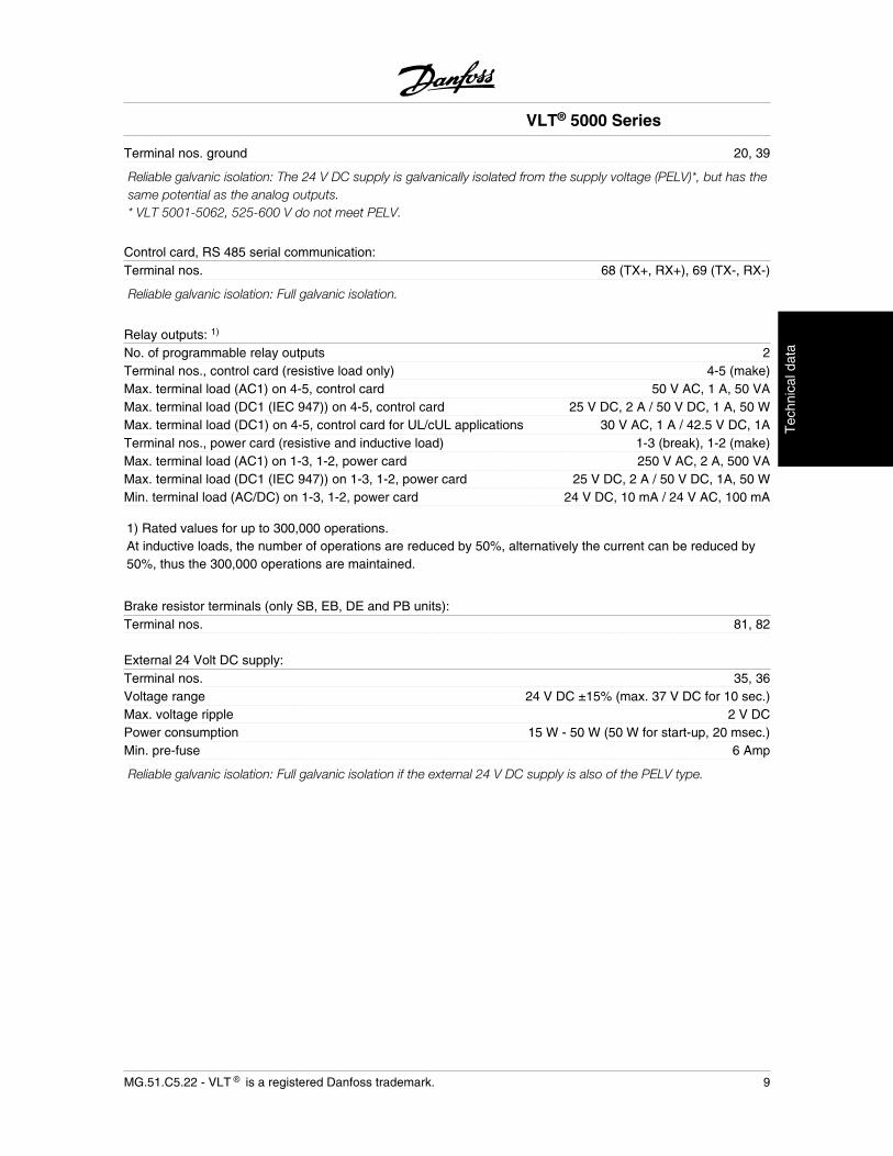
Terminal nos. ground 20, 39
Reliable galvanic isolation: The 24 V DC supply is galvanically isolated from the supply voltage (PELV)*, but has thesame potential as the analog outputs.* VLT 5001-5062, 525-600 V do not meet PELV.
Control card, RS 485 serial communication:Terminal nos. 68 (TX+, RX+), 69 (TX-, RX-)
Reliable galvanic isolation: Full galvanic isolation.
Relay outputs: 1)
No. of programmable relay outputs 2Terminal nos., control card (resistive load only) 4-5 (make)Max. terminal load (AC1) on 4-5, control card 50 V AC, 1 A, 50 VAMax. terminal load (DC1 (IEC 947)) on 4-5, control card 25 V DC, 2 A / 50 V DC, 1 A, 50 WMax. terminal load (DC1) on 4-5, control card for UL/cUL applications 30 V AC, 1 A / 42.5 V DC, 1ATerminal nos., power card (resistive and inductive load) 1-3 (break), 1-2 (make)Max. terminal load (AC1) on 1-3, 1-2, power card 250 V AC, 2 A, 500 VAMax. terminal load (DC1 (IEC 947)) on 1-3, 1-2, power card 25 V DC, 2 A / 50 V DC, 1A, 50 WMin. terminal load (AC/DC) on 1-3, 1-2, power card 24 V DC, 10 mA / 24 V AC, 100 mA
1) Rated values for up to 300,000 operations.At inductive loads, the number of operations are reduced by 50%, alternatively the current can be reduced by50%, thus the 300,000 operations are maintained.
Brake resistor terminals (only SB, EB, DE and PB units):Terminal nos. 81, 82
External 24 Volt DC supply:Terminal nos. 35, 36Voltage range 24 V DC ±15% (max. 37 V DC for 10 sec.)Max. voltage ripple 2 V DCPower consumption 15 W - 50 W (50 W for start-up, 20 msec.)Min. pre-fuse 6 Amp
Reliable galvanic isolation: Full galvanic isolation if the external 24 V DC supply is also of the PELV type.
VLT® 5000 Series
MG.51.C5.22 - VLT is a registered Danfoss trademark. 9
Tec
hnic
al d
ata
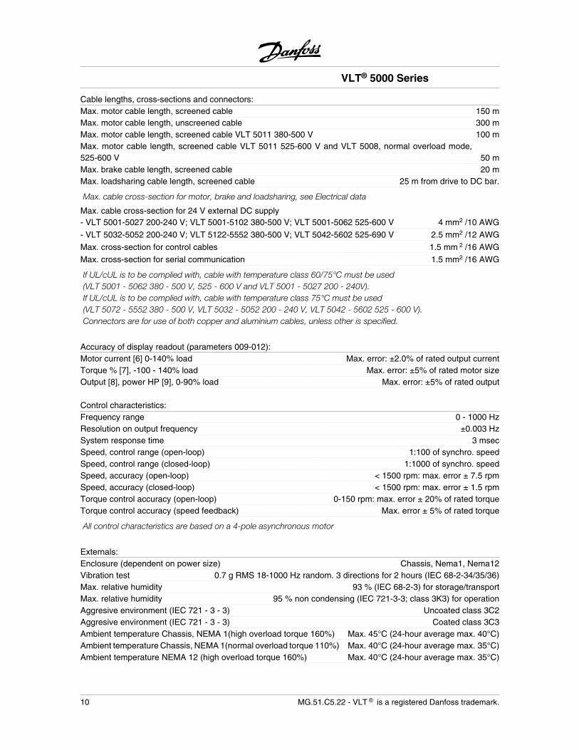
Cable lengths, cross-sections and connectors:Max. motor cable length, screened cable 150 mMax. motor cable length, unscreened cable 300 mMax. motor cable length, screened cable VLT 5011 380-500 V 100 mMax. motor cable length, screened cable VLT 5011 525-600 V and VLT 5008, normal overload mode,525-600 V 50 mMax. brake cable length, screened cable 20 mMax. loadsharing cable length, screened cable 25 m from drive to DC bar.
Max. cable cross-section for motor, brake and loadsharing, see Electrical data
Max. cable cross-section for 24 V external DC supply- VLT 5001-5027 200-240 V; VLT 5001-5102 380-500 V; VLT 5001-5062 525-600 V 4 mm2 /10 AWG
- VLT 5032-5052 200-240 V; VLT 5122-5552 380-500 V; VLT 5042-5602 525-690 V 2.5 mm2 /12 AWG
Max. cross-section for control cables 1.5 mm 2 /16 AWG
Max. cross-section for serial communication 1.5 mm2 /16 AWG
If UL/cUL is to be complied with, cable with temperature class 60/75°C must be used(VLT 5001 - 5062 380 - 500 V, 525 - 600 V and VLT 5001 - 5027 200 - 240V).If UL/cUL is to be complied with, cable with temperature class 75°C must be used(VLT 5072 - 5552 380 - 500 V, VLT 5032 - 5052 200 - 240 V, VLT 5042 - 5602 525 - 600 V).Connectors are for use of both copper and aluminium cables, unless other is specified.
Accuracy of display readout (parameters 009-012):Motor current [6] 0-140% load Max. error: ±2.0% of rated output currentTorque % [7], -100 - 140% load Max. error: ±5% of rated motor sizeOutput [8], power HP [9], 0-90% load Max. error: ±5% of rated output
Control characteristics:Frequency range 0 - 1000 HzResolution on output frequency ±0.003 HzSystem response time 3 msecSpeed, control range (open-loop) 1:100 of synchro. speedSpeed, control range (closed-loop) 1:1000 of synchro. speedSpeed, accuracy (open-loop) < 1500 rpm: max. error ± 7.5 rpmSpeed, accuracy (closed-loop) < 1500 rpm: max. error ± 1.5 rpmTorque control accuracy (open-loop) 0-150 rpm: max. error ± 20% of rated torqueTorque control accuracy (speed feedback) Max. error ± 5% of rated torque
All control characteristics are based on a 4-pole asynchronous motor
Externals:Enclosure (dependent on power size) Chassis, Nema1, Nema12Vibration test 0.7 g RMS 18-1000 Hz random. 3 directions for 2 hours (IEC 68-2-34/35/36)Max. relative humidity 93 % (IEC 68-2-3) for storage/transportMax. relative humidity 95 % non condensing (IEC 721-3-3; class 3K3) for operationAggresive environment (IEC 721 - 3 - 3) Uncoated class 3C2Aggresive environment (IEC 721 - 3 - 3) Coated class 3C3Ambient temperature Chassis, NEMA 1(high overload torque 160%) Max. 45°C (24-hour average max. 40°C)Ambient temperature Chassis, NEMA 1(normal overload torque 110%) Max. 40°C (24-hour average max. 35°C)Ambient temperature NEMA 12 (high overload torque 160%) Max. 40°C (24-hour average max. 35°C)
VLT® 5000 Series
10 MG.51.C5.22 - VLT is a registered Danfoss trademark.

Ambient temperature NEMA 12 (normal overload torque 110%) Max. 40°C (24-hour average max. 35°C)Ambient temperature NEMA 1/NEMA 121VLT 5011 500 V Max. 40°C (24-hour average max. 35°C)Ambient temperature NEMA 12 VLT 5042-5602, 525-690 V; and5122-5552, 380-500 V (high overload torque 160%) Max. 45°C (24-hour average max. 40°C)
Derating for high ambient temperature, see the Design Guide
Min. ambient temperature in full operation 0°CMin. ambient temperature at reduced performance -10°CTemperature during storage/transport -25 - +65/70°CMax. altitude above sea level 1000 m
Derating for altitude over 1000 m above sealevel, see the Design Guide
EMC standards applied, Emission EN 61000-6-3, EN 61000-6-4, EN 61800-3, EN 55011
EMC standards applied, ImmunityEN 61000-6-2, EN 61000-4-2, EN 61000-4-3, EN 61000-4-4
EN 61000-4-5, EN 61000-4-6, VDE 0160/1990.12
VLT 5001-5062, 525 - 600 V do not comply with EMC or Low Voltage Directives.
VLT® 5000 Series
MG.51.C5.22 - VLT is a registered Danfoss trademark. 11
Tec
hnic
al d
ata
VLT 5000 Series protection:
• Electronic motor thermal protection against overload.
• Temperature monitoring of heat-sink ensures that the drive cuts out if the temperature reaches 90°C forChassis and Nema 1. For NEMA 12 cut-out temperature is 80°C. An overtemperature can only be reset whenthe temperature of the heat-sink has fallen below 60°C.
For the units mentioned below, the limits are as follows:
- VLT 5122, 380-500 V, cuts out at 75°C and can be reset if the temperature has fallen below 60°C.- VLT 5152, 380-500 V, cuts out at 80°C and can be reset if the temperature has fallen below 60°C.- VLT 5202, 380-500 V, cuts out at 95°C and can be reset if the temperature has fallen below 65°C.- VLT 5252, 380-500 V, cuts out at 95°C and can be reset if the temperature has fallen below 65°C.- VLT 5302, 380-500 V, cuts out at 105°C and can be reset if the temperature has fallen below 75°C.- VLT 5352-5552, 380-500 V, cut out at 85°C and can be reset if the temperature has fallen below 60°C.- VLT 5042-5122, 525-690 V, cut out at 75°C and can be reset if the temperature has fallen below 60°C.- VLT 5152, 525-690 V, cuts out at 80°C and can be reset if the temperature has fallen below 60°C.- VLT 5202-5352, 525-690 V, cut out at 100°C and can be reset if the temperature has fallen below 70°C.- VLT 5402-5602, 525-690 V, cut out at 75°C and can be reset if the temperature has fallen below 60°C.
• The drive is protected against short-circuiting on motor terminals U, V, W.
• The drive is protected against earth fault on motor terminals U, V, W.
• Monitoring of the intermediate circuit voltage ensures that the drive cuts out if the intermediate circuit voltagegets too high or too low.
• If a motor phase is missing, the drive cuts out, see parameter 234 Motor phase monitor.
• If there is a mains fault, the drive is able to carry out a controlled deramping.
• If a mains phase is missing, the drive will cut out when a load is placed on the motor.
VLT® 5000 Series
12 MG.51.C5.22 - VLT is a registered Danfoss trademark.
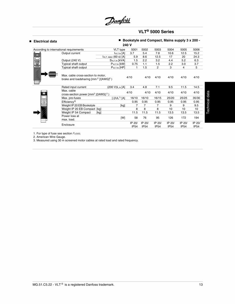
Electrical data Bookstyle and Compact, Mains supply 3 x 200 -240 V
According to international requirements VLT type 5001 5002 5003 5004 5005 5006Output current IVLT,N [A] 3.7 5.4 7.8 10.6 12.5 15.2
IVLT, MAX (60 s) [A] 5.9 8.6 12.5 17 20 24.3Output (240 V) SVLT,N [kVA] 1.5 2.2 3.2 4.4 5.2 6.3Typical shaft output PVLT,N [kW] 0.75 1.1 1.5 2.2 3.0 3.7Typical shaft output PVLT,N [HP] 1 1.5 2 3 4 5
Max. cable cross-section to motor,brake and loadsharing [mm 2 ]/[AWG]2 )
4/10 4/10 4/10 4/10 4/10 4/10
Rated input current (200 V)IL,N [A] 3.4 4.8 7.1 9.5 11.5 14.5Max. cablecross-section power [mm2 ]/[AWG] 2 )
4/10 4/10 4/10 4/10 4/10 4/10
Max. pre-fuses [-]/UL1) [A] 16/10 16/10 16/15 25/20 25/25 35/30Efficiency3) 0.95 0.95 0.95 0.95 0.95 0.95Weight IP 20 EB Bookstyle [kg] 7 7 7 9 9 9.5Weight IP 20 EB Compact [kg] 8 8 8 10 10 10Weight IP 54 Compact [kg] 11.5 11.5 11.5 13.5 13.5 13.5Power loss atmax. load.
[W] 58 76 95 126 172 194
EnclosureIP 20/IP54
IP 20/IP54
IP 20/IP54
IP 20/IP54
IP 20/IP54
IP 20/IP54
1. For type of fuse see section Fuses.2. American Wire Gauge.3. Measured using 30 m screened motor cables at rated load and rated frequency.
VLT® 5000 Series
MG.51.C5.22 - VLT is a registered Danfoss trademark. 13
Tec
hnic
al d
ata
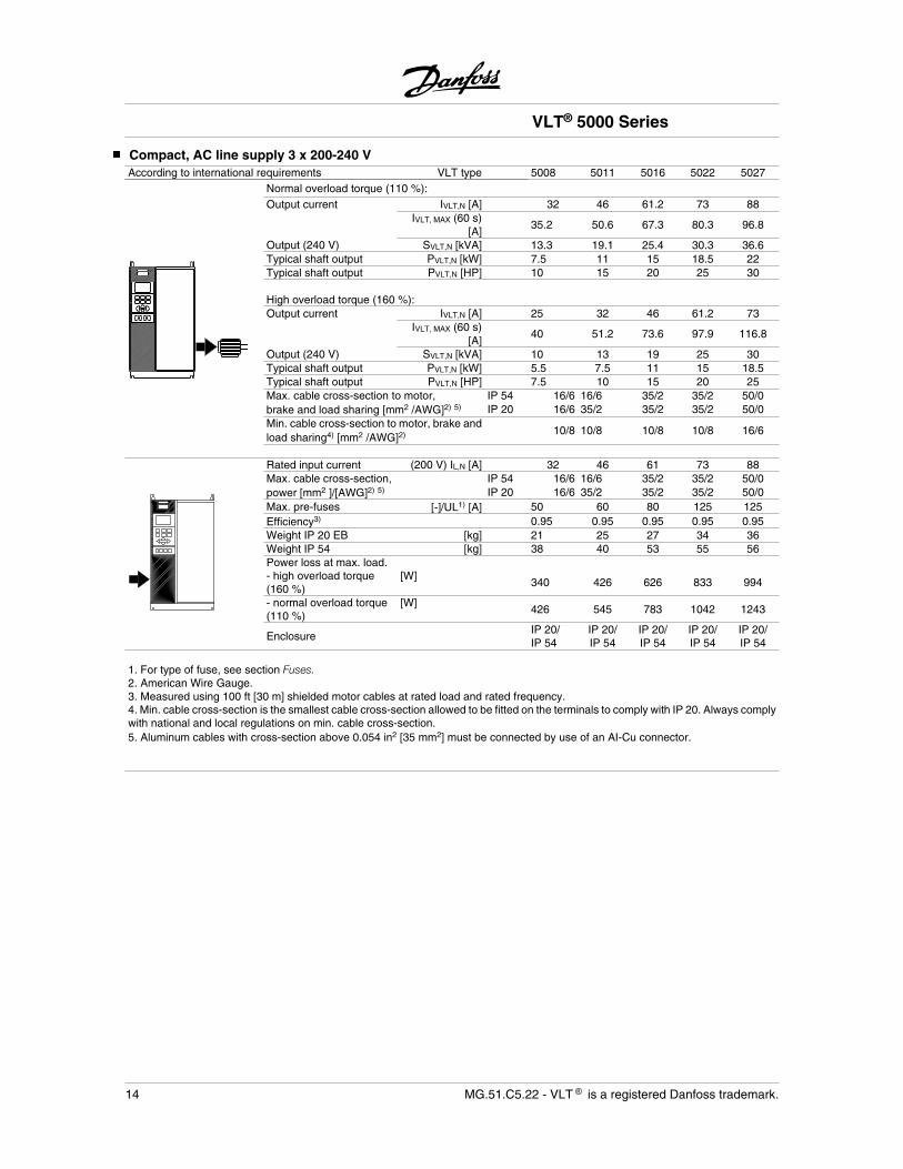
Compact, AC line supply 3 x 200-240 VAccording to international requirements VLT type 5008 5011 5016 5022 5027
Normal overload torque (110 %):Output current IVLT,N [A] 32 46 61.2 73 88
IVLT, MAX (60 s)[A]
35.2 50.6 67.3 80.3 96.8
Output (240 V) SVLT,N [kVA] 13.3 19.1 25.4 30.3 36.6Typical shaft output PVLT,N [kW] 7.5 11 15 18.5 22Typical shaft output PVLT,N [HP] 10 15 20 25 30 High overload torque (160 %): Output current IVLT,N [A] 25 32 46 61.2 73
IVLT, MAX (60 s)[A]
40 51.2 73.6 97.9 116.8
Output (240 V) SVLT,N [kVA] 10 13 19 25 30Typical shaft output PVLT,N [kW] 5.5 7.5 11 15 18.5Typical shaft output PVLT,N [HP] 7.5 10 15 20 25Max. cable cross-section to motor, IP 54 16/6 16/6 35/2 35/2 50/0brake and load sharing [mm2 /AWG]2) 5) IP 20 16/6 35/2 35/2 35/2 50/0Min. cable cross-section to motor, brake andload sharing4) [mm2 /AWG]2) 10/8 10/8 10/8 10/8 16/6
Rated input current (200 V) IL,N [A] 32 46 61 73 88Max. cable cross-section, IP 54 16/6 16/6 35/2 35/2 50/0power [mm2 ]/[AWG]2) 5) IP 20 16/6 35/2 35/2 35/2 50/0Max. pre-fuses [-]/UL1) [A] 50 60 80 125 125Efficiency3) 0.95 0.95 0.95 0.95 0.95Weight IP 20 EB [kg] 21 25 27 34 36Weight IP 54 [kg] 38 40 53 55 56Power loss at max. load. - high overload torque(160 %)
[W]340 426 626 833 994
- normal overload torque(110 %)
[W]426 545 783 1042 1243
EnclosureIP 20/IP 54
IP 20/IP 54
IP 20/IP 54
IP 20/IP 54
IP 20/IP 54
1. For type of fuse, see section Fuses.2. American Wire Gauge.3. Measured using 100 ft [30 m] shielded motor cables at rated load and rated frequency.4. Min. cable cross-section is the smallest cable cross-section allowed to be fitted on the terminals to comply with IP 20. Always complywith national and local regulations on min. cable cross-section.5. Aluminum cables with cross-section above 0.054 in2 [35 mm2] must be connected by use of an AI-Cu connector.
VLT® 5000 Series
14 MG.51.C5.22 - VLT is a registered Danfoss trademark.
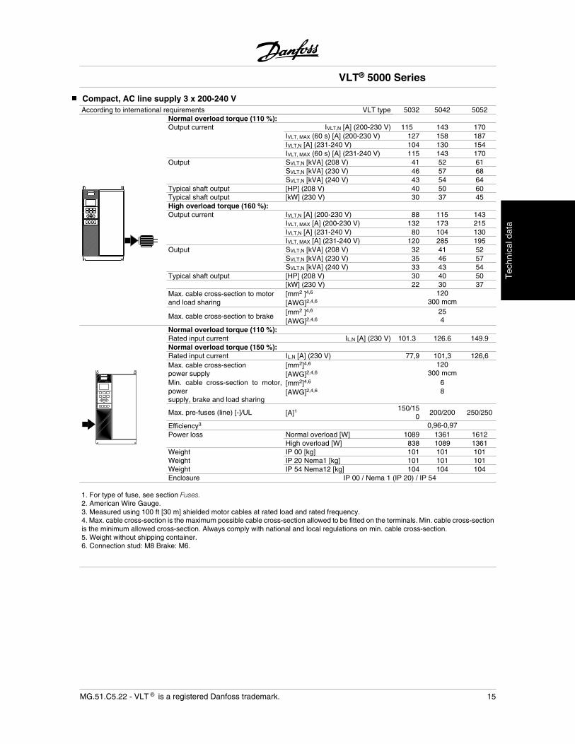
Compact, AC line supply 3 x 200-240 VAccording to international requirements VLT type 5032 5042 5052
Normal overload torque (110 %):Output current IVLT,N [A] (200-230 V) 115 143 170
IVLT, MAX (60 s) [A] (200-230 V) 127 158 187IVLT,N [A] (231-240 V) 104 130 154IVLT, MAX (60 s) [A] (231-240 V) 115 143 170
Output SVLT,N [kVA] (208 V) 41 52 61SVLT,N [kVA] (230 V) 46 57 68SVLT,N [kVA] (240 V) 43 54 64
Typical shaft output [HP] (208 V) 40 50 60Typical shaft output [kW] (230 V) 30 37 45High overload torque (160 %):Output current IVLT,N [A] (200-230 V) 88 115 143
IVLT, MAX [A] (200-230 V) 132 173 215IVLT,N [A] (231-240 V) 80 104 130IVLT, MAX [A] (231-240 V) 120 285 195
Output SVLT,N [kVA] (208 V) 32 41 52SVLT,N [kVA] (230 V) 35 46 57SVLT,N [kVA] (240 V) 33 43 54
Typical shaft output [HP] (208 V) 30 40 50[kW] (230 V) 22 30 37
Max. cable cross-section to motorand load sharing
[mm2 ]4,6
[AWG]2,4,6
120300 mcm
Max. cable cross-section to brake[mm2 ]4,6
[AWG]2,4,6
254
Normal overload torque (110 %):Rated input current IL,N [A] (230 V) 101.3 126.6 149.9Normal overload torque (150 %):Rated input current IL,N [A] (230 V) 77,9 101,3 126,6Max. cable cross-sectionpower supply
[mm2]4,6
[AWG]2,4,6
120300 mcm
Min. cable cross-section to motor,powersupply, brake and load sharing
[mm2]4,6
[AWG]2,4,6
68
Max. pre-fuses (line) [-]/UL [A]1150/15
0200/200 250/250
Efficiency3 0,96-0,97Power loss Normal overload [W] 1089 1361 1612
High overload [W] 838 1089 1361Weight IP 00 [kg] 101 101 101Weight IP 20 Nema1 [kg] 101 101 101Weight IP 54 Nema12 [kg] 104 104 104Enclosure IP 00 / Nema 1 (IP 20) / IP 54
1. For type of fuse, see section Fuses.2. American Wire Gauge.3. Measured using 100 ft [30 m] shielded motor cables at rated load and rated frequency.4. Max. cable cross-section is the maximum possible cable cross-section allowed to be fitted on the terminals. Min. cable cross-sectionis the minimum allowed cross-section. Always comply with national and local regulations on min. cable cross-section.5. Weight without shipping container.6. Connection stud: M8 Brake: M6.
VLT® 5000 Series
MG.51.C5.22 - VLT is a registered Danfoss trademark. 15
Tec
hnic
al d
ata
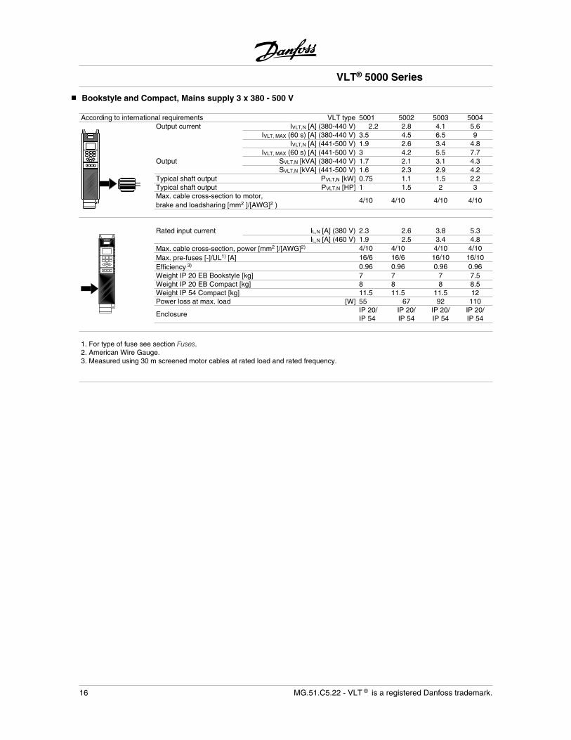
Bookstyle and Compact, Mains supply 3 x 380 - 500 V
According to international requirements VLT type 5001 5002 5003 5004Output current IVLT,N [A] (380-440 V) 2.2 2.8 4.1 5.6
IVLT, MAX (60 s) [A] (380-440 V) 3.5 4.5 6.5 9IVLT,N [A] (441-500 V) 1.9 2.6 3.4 4.8
IVLT, MAX (60 s) [A] (441-500 V) 3 4.2 5.5 7.7Output SVLT,N [kVA] (380-440 V) 1.7 2.1 3.1 4.3
SVLT,N [kVA] (441-500 V) 1.6 2.3 2.9 4.2Typical shaft output PVLT,N [kW] 0.75 1.1 1.5 2.2Typical shaft output PVLT,N [HP] 1 1.5 2 3Max. cable cross-section to motor,brake and loadsharing [mm2 ]/[AWG]2 )
4/10 4/10 4/10 4/10
Rated input current IL,N [A] (380 V) 2.3 2.6 3.8 5.3
IL,N [A] (460 V) 1.9 2.5 3.4 4.8Max. cable cross-section, power [mm2 ]/[AWG]2) 4/10 4/10 4/10 4/10Max. pre-fuses [-]/UL1) [A] 16/6 16/6 16/10 16/10Efficiency 3) 0.96 0.96 0.96 0.96Weight IP 20 EB Bookstyle [kg] 7 7 7 7.5Weight IP 20 EB Compact [kg] 8 8 8 8.5Weight IP 54 Compact [kg] 11.5 11.5 11.5 12Power loss at max. load [W] 55 67 92 110
EnclosureIP 20/IP 54
IP 20/IP 54
IP 20/IP 54
IP 20/IP 54
1. For type of fuse see section Fuses.2. American Wire Gauge.3. Measured using 30 m screened motor cables at rated load and rated frequency.
VLT® 5000 Series
16 MG.51.C5.22 - VLT is a registered Danfoss trademark.
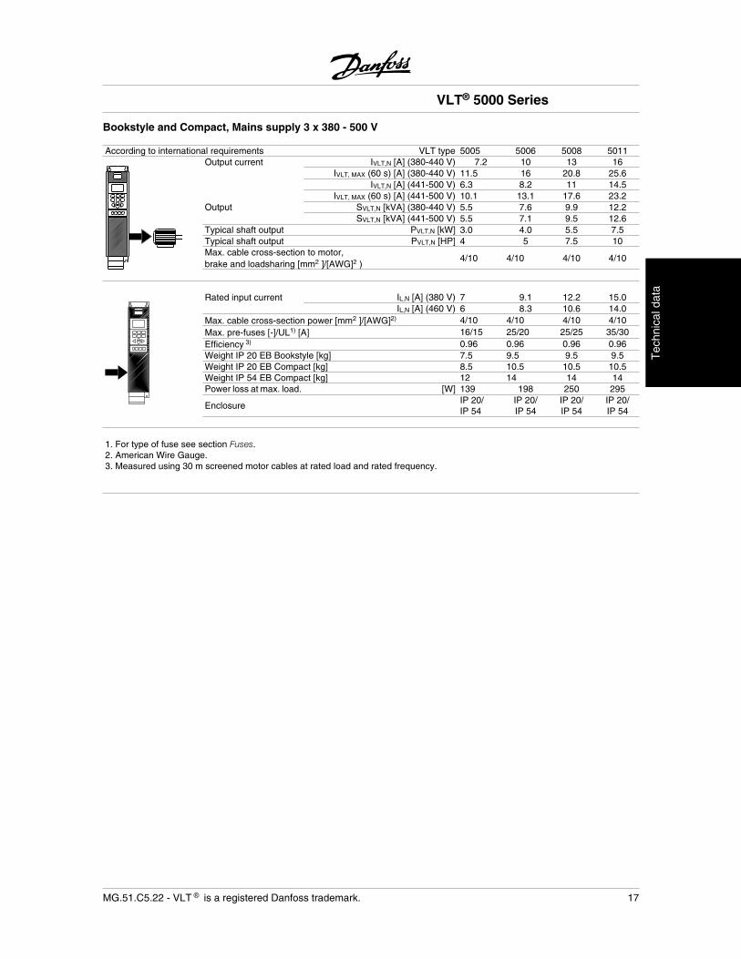
Bookstyle and Compact, Mains supply 3 x 380 - 500 V
According to international requirements VLT type 5005 5006 5008 5011Output current IVLT,N [A] (380-440 V) 7.2 10 13 16
IVLT, MAX (60 s) [A] (380-440 V) 11.5 16 20.8 25.6IVLT,N [A] (441-500 V) 6.3 8.2 11 14.5
IVLT, MAX (60 s) [A] (441-500 V) 10.1 13.1 17.6 23.2Output SVLT,N [kVA] (380-440 V) 5.5 7.6 9.9 12.2
SVLT,N [kVA] (441-500 V) 5.5 7.1 9.5 12.6Typical shaft output PVLT,N [kW] 3.0 4.0 5.5 7.5Typical shaft output PVLT,N [HP] 4 5 7.5 10Max. cable cross-section to motor,brake and loadsharing [mm2 ]/[AWG]2 )
4/10 4/10 4/10 4/10
Rated input current IL,N [A] (380 V) 7 9.1 12.2 15.0
IL,N [A] (460 V) 6 8.3 10.6 14.0Max. cable cross-section power [mm2 ]/[AWG]2) 4/10 4/10 4/10 4/10Max. pre-fuses [-]/UL1) [A] 16/15 25/20 25/25 35/30Efficiency 3) 0.96 0.96 0.96 0.96Weight IP 20 EB Bookstyle [kg] 7.5 9.5 9.5 9.5Weight IP 20 EB Compact [kg] 8.5 10.5 10.5 10.5Weight IP 54 EB Compact [kg] 12 14 14 14Power loss at max. load. [W] 139 198 250 295
EnclosureIP 20/IP 54
IP 20/IP 54
IP 20/IP 54
IP 20/IP 54
1. For type of fuse see section Fuses.2. American Wire Gauge.3. Measured using 30 m screened motor cables at rated load and rated frequency.
VLT® 5000 Series
MG.51.C5.22 - VLT is a registered Danfoss trademark. 17
Tec
hnic
al d
ata
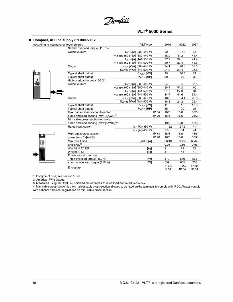
Compact, AC line supply 3 x 380-500 VAccording to international requirements VLT type 5016 5022 5027
Normal overload torque (110 %):Output current IVLT,N [A] (380-440 V) 32 37.5 44
IVLT, MAX (60 s) [A] (380-440 V) 35.2 41.3 48.4IVLT,N [A] (441-500 V) 27.9 34 41.4
IVLT, MAX (60 s) [A] (441-500 V) 30.7 37.4 45.5Output SVLT,N [kVA] (380-440 V) 24.4 28.6 33.5
SVLT,N [kVA] (441-500 V) 24.2 29.4 35.8Typical shaft output PVLT,N [kW] 15 18.5 22Typical shaft output PVLT,N [HP] 20 25 30High overload torque (160 %): Output current IVLT,N [A] (380-440 V) 24 32 37.5
IVLT, MAX (60 s) [A] (380-440 V) 38.4 51.2 60IVLT,N [A] (441-500 V) 21.7 27.9 34
IVLT, MAX (60 s) [A] (441-500 V) 34.7 44.6 54.4Output SVLT,N [kVA] (380-440 V) 18.3 24.4 28.6
SVLT,N [kVA] (441-500 V) 18.8 24.2 29.4Typical shaft output PVLT,N [kW] 11 15 18.5Typical shaft output PVLT,N [HP] 15 20 25Max. cable cross-section to motor, IP 54 16/6 16/6 16/6brake and load sharing [mm2 ]/[AWG]2) IP 20 16/6 16/6 35/2Min. cable cross-section to motor, brake and load sharing [mm2]/[AWG]2) 4) 10/8 10/8 10/8Rated input current IL,N [A] (380 V) 32 37.5 44
IL,N [A] (460 V) 27.6 34 41Max. cable cross-section, IP 54 16/6 16/6 16/6power [mm 2 ]/[AWG] IP 20 16/6 16/6 35/2Max. pre-fuses [-]/UL1) [A] 63/40 63/50 63/60Efficiency3) 0.96 0.96 0.96Weight IP 20 EB [kg] 21 22 27Weight IP 54 [kg] 41 41 42Power loss at max. load. - high overload torque (160 %) [W] 419 559 655- normal overload torque (110 %) [W] 559 655 768
EnclosureIP 20/IP 54
IP 20/IP 54
IP 20/IP 54
1. For type of fuse, see section Fuses.2. American Wire Gauge.3. Measured using 100 ft [30 m] shielded motor cables at rated load and rated frequency.4. Min. cable cross-section is the smallest cable cross-section allowed to be fitted on the terminals to comply with IP 20. Always complywith national and local regulations on min. cable cross-section.
VLT® 5000 Series
18 MG.51.C5.22 - VLT is a registered Danfoss trademark.
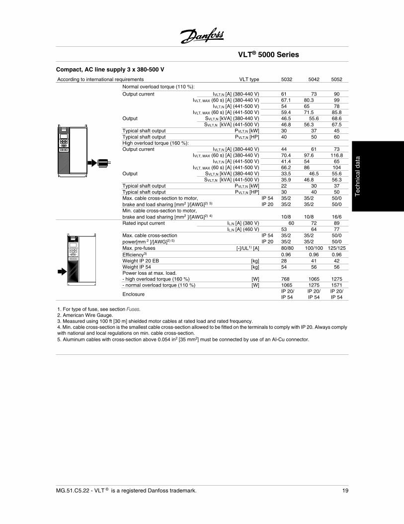
Compact, AC line supply 3 x 380-500 V
According to international requirements VLT type 5032 5042 5052
Normal overload torque (110 %):
Output current IVLT,N [A] (380-440 V) 61 73 90IVLT, MAX (60 s) [A] (380-440 V) 67.1 80.3 99
IVLT,N [A] (441-500 V) 54 65 78IVLT, MAX (60 s) [A] (441-500 V) 59.4 71.5 85.8
Output SVLT,N [kVA] (380-440 V) 46.5 55.6 68.6SVLT,N [kVA] (441-500 V) 46.8 56.3 67.5
Typical shaft output PVLT,N [kW] 30 37 45Typical shaft output PVLT,N [HP] 40 50 60High overload torque (160 %): Output current IVLT,N [A] (380-440 V) 44 61 73
IVLT, MAX (60 s) [A] (380-440 V) 70.4 97.6 116.8IVLT,N [A] (441-500 V) 41.4 54 65
IVLT, MAX (60 s) [A] (441-500 V) 66.2 86 104Output SVLT,N [kVA] (380-440 V) 33.5 46.5 55.6
SVLT,N [kVA] (441-500 V) 35.9 46.8 56.3Typical shaft output PVLT,N [kW] 22 30 37Typical shaft output PVLT,N [HP] 30 40 50Max. cable cross-section to motor, IP 54 35/2 35/2 50/0brake and load sharing [mm2 ]/[AWG]2) 5) IP 20 35/2 35/2 50/0Min. cable cross-section to motor, brake and load sharing [mm2 ]/[AWG]2) 4) 10/8 10/8 16/6Rated input current IL,N [A] (380 V) 60 72 89
IL,N [A] (460 V) 53 64 77Max. cable cross-section IP 54 35/2 35/2 50/0power[mm 2 ]/[AWG]2) 5) IP 20 35/2 35/2 50/0Max. pre-fuses [-]/UL1) [A] 80/80 100/100 125/125Efficiency3) 0.96 0.96 0.96Weight IP 20 EB [kg] 28 41 42Weight IP 54 [kg] 54 56 56Power loss at max. load. - high overload torque (160 %) [W] 768 1065 1275- normal overload torque (110 %) [W] 1065 1275 1571
EnclosureIP 20/IP 54
IP 20/IP 54
IP 20/IP 54
1. For type of fuse, see section Fuses.2. American Wire Gauge.3. Measured using 100 ft [30 m] shielded motor cables at rated load and rated frequency.4. Min. cable cross-section is the smallest cable cross-section allowed to be fitted on the terminals to comply with IP 20. Always complywith national and local regulations on min. cable cross-section.5. Aluminum cables with cross-section above 0.054 in2 [35 mm2] must be connected by use of an AI-Cu connector.
VLT® 5000 Series
MG.51.C5.22 - VLT is a registered Danfoss trademark. 19
Tec
hnic
al d
ata
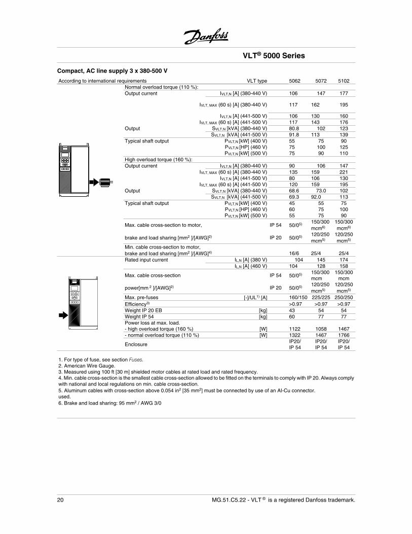
Compact, AC line supply 3 x 380-500 V
According to international requirements VLT type 5062 5072 5102Normal overload torque (110 %):Output current IVLT,N [A] (380-440 V) 106 147 177
IVLT, MAX (60 s) [A] (380-440 V) 117 162 195
IVLT,N [A] (441-500 V) 106 130 160IVLT, MAX (60 s) [A] (441-500 V) 117 143 176
Output SVLT,N [kVA] (380-440 V) 80.8 102 123SVLT,N [kVA] (441-500 V) 91.8 113 139
Typical shaft output PVLT,N [kW] (400 V) 55 75 90PVLT,N [HP] (460 V) 75 100 125PVLT,N [kW] (500 V) 75 90 110
High overload torque (160 %): Output current IVLT,N [A] (380-440 V) 90 106 147
IVLT, MAX (60 s) [A] (380-440 V) 135 159 221IVLT,N [A] (441-500 V) 80 106 130
IVLT, MAX (60 s) [A] (441-500 V) 120 159 195Output SVLT,N [kVA] (380-440 V) 68.6 73.0 102
SVLT,N [kVA] (441-500 V) 69.3 92.0 113Typical shaft output PVLT,N [kW] (400 V) 45 55 75
PVLT,N [HP] (460 V) 60 75 100PVLT,N [kW] (500 V) 55 75 90
Max. cable cross-section to motor, IP 54 50/05) 150/300mcm6)
150/300mcm6)
brake and load sharing [mm2 ]/[AWG]2) IP 20 50/05) 120/250mcm5)
120/250mcm5)
Min. cable cross-section to motor, brake and load sharing [mm2 ]/[AWG]4) 16/6 25/4 25/4Rated input current IL,N [A] (380 V) 104 145 174
IL,N [A] (460 V) 104 128 158
Max. cable cross-section IP 54 50/05) 150/300mcm
150/300mcm
power[mm 2 ]/[AWG]2) IP 20 50/05) 120/250mcm5)
120/250mcm5)
Max. pre-fuses [-]/UL1) [A] 160/150 225/225 250/250Efficiency3) >0.97 >0.97 >0.97Weight IP 20 EB [kg] 43 54 54Weight IP 54 [kg] 60 77 77Power loss at max. load. - high overload torque (160 %) [W] 1122 1058 1467- normal overload torque (110 %) [W] 1322 1467 1766
EnclosureIP20/IP 54
IP20/IP 54
IP20/IP 54
1. For type of fuse, see section Fuses.2. American Wire Gauge.3. Measured using 100 ft [30 m] shielded motor cables at rated load and rated frequency.4. Min. cable cross-section is the smallest cable cross-section allowed to be fitted on the terminals to comply with IP 20. Always complywith national and local regulations on min. cable cross-section.5. Aluminum cables with cross-section above 0.054 in2 [35 mm2] must be connected by use of an AI-Cu connector.used.6. Brake and load sharing: 95 mm2 / AWG 3/0
VLT® 5000 Series
20 MG.51.C5.22 - VLT is a registered Danfoss trademark.
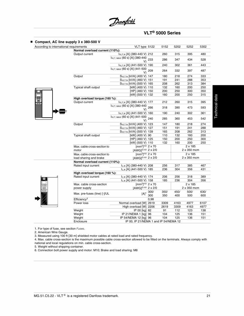
Compact, AC line supply 3 x 380-500 VAccording to international requirements VLT type 5122 5152 5202 5252 5302
Normal overload current (110%):Output current IVLT,N [A] (380-440 V) 212 260 315 395 480
IVLT, MAX (60 s) [A] (380-440V)
233 286 347 434 528
IVLT,N [A] (441-500 V) 190 240 302 361 443IVLT, MAX (60 s) [A] (441-500
V)209 264 332 397 487
Output SVLT,N [kVA] (400 V) 147 180 218 274 333SVLT,N [kVA] (460 V) 151 191 241 288 353SVLT,N [kVA] (500 V) 165 208 262 313 384
Typical shaft output [kW] (400 V) 110 132 160 200 250 [HP] (460 V) 150 200 250 300 350
[kW] (500 V) 132 160 200 250 315High overload torque (160 %):Output current IVLT,N [A] (380-440 V) 177 212 260 315 395
IVLT, MAX (60 s) [A] (380-440V)
266 318 390 473 593
IVLT,N [A] (441-500 V) 160 190 240 302 361IVLT, MAX (60 s) [A] (441-500
V)240 285 360 453 542
Output SVLT,N [kVA] (400 V) 123 147 180 218 274SVLT,N [kVA] (460 V) 127 151 191 241 288SVLT,N [kVA] (500 V) 139 165 208 262 313
Typical shaft output [kW] (400 V) 90 110 132 160 200 [HP] (460 V) 125 150 200 250 300
[kW] (500 V) 110 132 160 200 250Max. cable cross-section tomotor
[mm2]4,6
[AWG]2,4,6
2 x 702 x 2/0
2 x 1852 x 350 mcm
Max. cable cross-section toload sharing and brake
[mm2]4,6
[AWG]2,4,6
2 x 702 x 2/0
2 x 1852 x 350 mcm
Normal overload current (110%):Rated input current IL,N [A] (380-440 V) 208 256 317 385 467
IL,N [A] (441-500 V) 185 236 304 356 431High overload torque (160 %):Rated input current IL,N [A] (380-440 V) 174 206 256 318 389
IL,N [A] (441-500 V) 158 185 236 304 356Max. cable cross-sectionpower supply
[mm2]4,6
[AWG]2,4,62 x 702 x 2/0
2 x 1852 x 350 mcm
Max. pre-fuses (line) [-]/UL [A]1300/300
350/350
450/400
500/500
630/600
Efficiency3 0,98Power loss Normal overload [W] 2619 3309 4163 4977 6107
High overload [W] 2206 2619 3309 4163 4977Weight IP 00 [kg] 82 91 112 123 138Weight IP 21/NEMA 1 [kg] 96 104 125 136 151Weight IP 54/NEMA 12 [kg] 96 104 125 136 151Enclosure IP 00, IP 21/NEMA 1 and IP 54/NEMA 12
1. For type of fuse, see section Fuses.2. American Wire Gauge.3. Measured using 100 ft [30 m] shielded motor cables at rated load and rated frequency.4. Max. cable cross-section is the maximum possible cable cross-section allowed to be fitted on the terminals. Always comply withnational and local regulations on min. cable cross-section.5. Weight without shipping container.6. Connection bolt power supply and motor: M10; Brake and load sharing: M8
VLT® 5000 Series
MG.51.C5.22 - VLT is a registered Danfoss trademark. 21
Tec
hnic
al d
ata
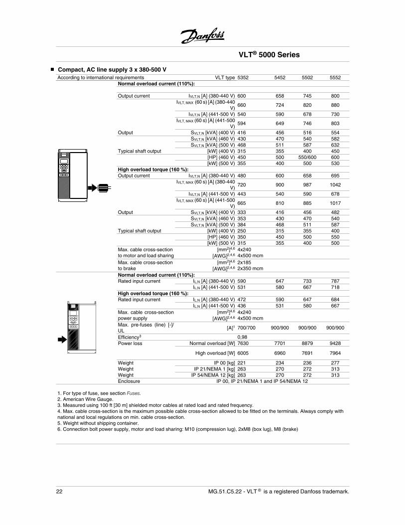
Compact, AC line supply 3 x 380-500 VAccording to international requirements VLT type 5352 5452 5502 5552
Normal overload current (110%):
Output current IVLT,N [A] (380-440 V) 600 658 745 800IVLT, MAX (60 s) [A] (380-440
V)660 724 820 880
IVLT,N [A] (441-500 V) 540 590 678 730IVLT, MAX (60 s) [A] (441-500
V)594 649 746 803
Output SVLT,N [kVA] (400 V) 416 456 516 554SVLT,N [kVA] (460 V) 430 470 540 582SVLT,N [kVA] (500 V) 468 511 587 632
Typical shaft output [kW] (400 V) 315 355 400 450[HP] (460 V) 450 500 550/600 600[kW] (500 V) 355 400 500 530
High overload torque (160 %):Output current IVLT,N [A] (380-440 V) 480 600 658 695
IVLT, MAX (60 s) [A] (380-440V)
720 900 987 1042
IVLT,N [A] (441-500 V) 443 540 590 678IVLT, MAX (60 s) [A] (441-500
V)665 810 885 1017
Output SVLT,N [kVA] (400 V) 333 416 456 482SVLT,N [kVA] (460 V) 353 430 470 540SVLT,N [kVA] (500 V) 384 468 511 587
Typical shaft output [kW] (400 V) 250 315 355 400[HP] (460 V) 350 450 500 550[kW] (500 V) 315 355 400 500
Max. cable cross-sectionto motor and load sharing
[mm2]4,6
[AWG]2,4,64x2404x500 mcm
Max. cable cross-sectionto brake
[mm2]4,6
[AWG]2,4,62x1852x350 mcm
Normal overload current (110%):Rated input current IL,N [A] (380-440 V) 590 647 733 787
IL,N [A] (441-500 V) 531 580 667 718High overload torque (160 %):Rated input current IL,N [A] (380-440 V) 472 590 647 684
IL,N [A] (441-500 V) 436 531 580 667Max. cable cross-sectionpower supply
[mm2]4,6
[AWG]2,4,64x2404x500 mcm
Max. pre-fuses (line) [-]/UL [A]1 700/700 900/900 900/900 900/900
Efficiency3 0,98Power loss Normal overload [W] 7630 7701 8879 9428
High overload [W] 6005 6960 7691 7964
Weight IP 00 [kg] 221 234 236 277Weight IP 21/NEMA 1 [kg] 263 270 272 313Weight IP 54/NEMA 12 [kg] 263 270 272 313Enclosure IP 00, IP 21/NEMA 1 and IP 54/NEMA 12
1. For type of fuse, see section Fuses.2. American Wire Gauge.3. Measured using 100 ft [30 m] shielded motor cables at rated load and rated frequency.4. Max. cable cross-section is the maximum possible cable cross-section allowed to be fitted on the terminals. Always comply withnational and local regulations on min. cable cross-section.5. Weight without shipping container.6. Connection bolt power supply, motor and load sharing: M10 (compression lug), 2xM8 (box lug), M8 (brake)
VLT® 5000 Series
22 MG.51.C5.22 - VLT is a registered Danfoss trademark.
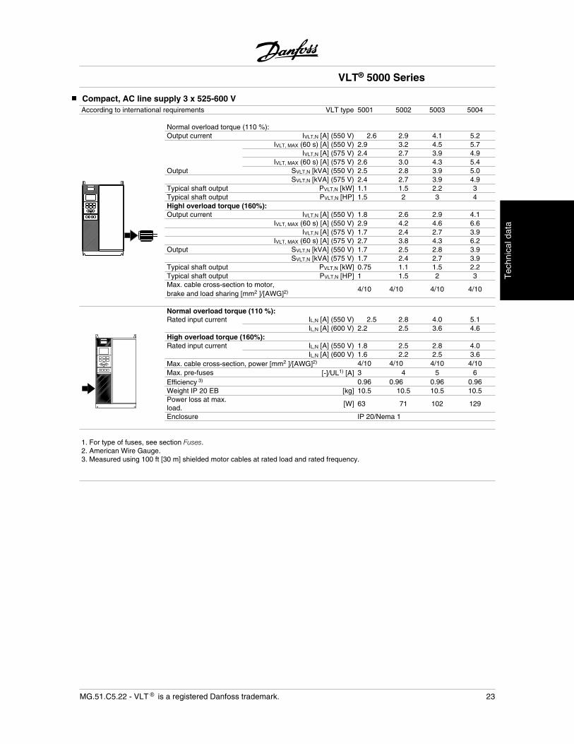
Compact, AC line supply 3 x 525-600 VAccording to international requirements VLT type 5001 5002 5003 5004
Normal overload torque (110 %): Output current IVLT,N [A] (550 V) 2.6 2.9 4.1 5.2
IVLT, MAX (60 s) [A] (550 V) 2.9 3.2 4.5 5.7IVLT,N [A] (575 V) 2.4 2.7 3.9 4.9
IVLT, MAX (60 s) [A] (575 V) 2.6 3.0 4.3 5.4Output SVLT,N [kVA] (550 V) 2.5 2.8 3.9 5.0
SVLT,N [kVA] (575 V) 2.4 2.7 3.9 4.9Typical shaft output PVLT,N [kW] 1.1 1.5 2.2 3Typical shaft output PVLT,N [HP] 1.5 2 3 4Highl overload torque (160%):Output current IVLT,N [A] (550 V) 1.8 2.6 2.9 4.1
IVLT, MAX (60 s) [A] (550 V) 2.9 4.2 4.6 6.6IVLT,N [A] (575 V) 1.7 2.4 2.7 3.9
IVLT, MAX (60 s) [A] (575 V) 2.7 3.8 4.3 6.2Output SVLT,N [kVA] (550 V) 1.7 2.5 2.8 3.9
SVLT,N [kVA] (575 V) 1.7 2.4 2.7 3.9Typical shaft output PVLT,N [kW] 0.75 1.1 1.5 2.2Typical shaft output PVLT,N [HP] 1 1.5 2 3Max. cable cross-section to motor,brake and load sharing [mm2 ]/[AWG]2) 4/10 4/10 4/10 4/10
Normal overload torque (110 %): Rated input current IL,N [A] (550 V) 2.5 2.8 4.0 5.1
IL,N [A] (600 V) 2.2 2.5 3.6 4.6High overload torque (160%):Rated input current IL,N [A] (550 V) 1.8 2.5 2.8 4.0
IL,N [A] (600 V) 1.6 2.2 2.5 3.6Max. cable cross-section, power [mm2 ]/[AWG]2) 4/10 4/10 4/10 4/10Max. pre-fuses [-]/UL1) [A] 3 4 5 6Efficiency 3) 0.96 0.96 0.96 0.96Weight IP 20 EB [kg] 10.5 10.5 10.5 10.5Power loss at max.load.
[W] 63 71 102 129
Enclosure IP 20/Nema 1
1. For type of fuses, see section Fuses.2. American Wire Gauge.3. Measured using 100 ft [30 m] shielded motor cables at rated load and rated frequency.
VLT® 5000 Series
MG.51.C5.22 - VLT is a registered Danfoss trademark. 23
Tec
hnic
al d
ata
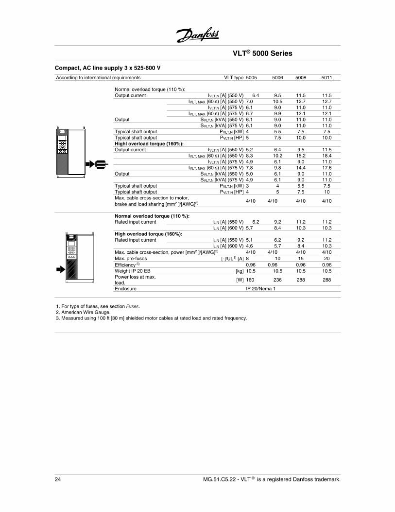
Compact, AC line supply 3 x 525-600 V
According to international requirements VLT type 5005 5006 5008 5011
Normal overload torque (110 %): Output current IVLT,N [A] (550 V) 6.4 9.5 11.5 11.5
IVLT, MAX (60 s) [A] (550 V) 7.0 10.5 12.7 12.7IVLT,N [A] (575 V) 6.1 9.0 11.0 11.0
IVLT, MAX (60 s) [A] (575 V) 6.7 9.9 12.1 12.1Output SVLT,N [kVA] (550 V) 6.1 9.0 11.0 11.0
SVLT,N [kVA] (575 V) 6.1 9.0 11.0 11.0Typical shaft output PVLT,N [kW] 4 5.5 7.5 7.5Typical shaft output PVLT,N [HP] 5 7.5 10.0 10.0Highl overload torque (160%):Output current IVLT,N [A] (550 V) 5.2 6.4 9.5 11.5
IVLT, MAX (60 s) [A] (550 V) 8.3 10.2 15.2 18.4IVLT,N [A] (575 V) 4.9 6.1 9.0 11.0
IVLT, MAX (60 s) [A] (575 V) 7.8 9.8 14.4 17.6Output SVLT,N [kVA] (550 V) 5.0 6.1 9.0 11.0
SVLT,N [kVA] (575 V) 4.9 6.1 9.0 11.0Typical shaft output PVLT,N [kW] 3 4 5.5 7.5Typical shaft output PVLT,N [HP] 4 5 7.5 10Max. cable cross-section to motor,brake and load sharing [mm2 ]/[AWG]2) 4/10 4/10 4/10 4/10
Normal overload torque (110 %): Rated input current IL,N [A] (550 V) 6.2 9.2 11.2 11.2
IL,N [A] (600 V) 5.7 8.4 10.3 10.3High overload torque (160%):Rated input current IL,N [A] (550 V) 5.1 6.2 9.2 11.2
IL,N [A] (600 V) 4.6 5.7 8.4 10.3Max. cable cross-section, power [mm2 ]/[AWG]2) 4/10 4/10 4/10 4/10Max. pre-fuses [-]/UL1) [A] 8 10 15 20Efficiency 3) 0.96 0.96 0.96 0.96Weight IP 20 EB [kg] 10.5 10.5 10.5 10.5Power loss at max.load.
[W] 160 236 288 288
Enclosure IP 20/Nema 1
1. For type of fuses, see section Fuses.2. American Wire Gauge.3. Measured using 100 ft [30 m] shielded motor cables at rated load and rated frequency.
VLT® 5000 Series
24 MG.51.C5.22 - VLT is a registered Danfoss trademark.

Compact, AC line supply 3 x 525-600 VAccording to international requirements VLT type 5016 5022 5027
Normal overload torque (110 %):Output current IVLT,N [A] (550 V) 23 28 34
IVLT, MAX (60 s) [A] (550 V) 25 31 37IVLT,N [A] (575 V) 22 27 32
IVLT, MAX (60 s) [A] (575 V) 24 30 35Output SVLT,N [kVA] (550 V) 22 27 32
SVLT,N [kVA] (575 V) 22 27 32Typical shaft output PVLT,N [kW] 15 18.5 22Typical shaft output PVLT,N [HP] 20 25 30High overload torque (160 %): Output current IVLT,N [A] (550 V) 18 23 28
IVLT, MAX (60 s) [A] (550 V) 29 37 45IVLT,N [A] (575 V) 17 22 27
IVLT, MAX (60 s) [A] (575 V) 27 35 43Output SVLT,N [kVA] (550 V) 17 22 27
SVLT,N [kVA] (575 V) 17 22 27Typical shaft output PVLT,N [kW] 11 15 18.5Typical shaft output PVLT,N [HP] 15 20 25Max. cable cross-section to motor, 16 16 35brake and load sharing [mm2 ]/[AWG]2) 6 6 2Min. cable cross-section to motor, 0.5 0.5 10brake and load sharing [mm2]/[AWG]4) 20 20 8Normal overload torque (110 %): Rated input current IL,N [A] (550 V) 22 27 33
IL,N [A] (600 V) 21 25 30High overload torque (160 %): Rated input current IL,N [A] (550 V) 18 22 27
IL,N [A] (600 V) 16 21 25Max. cable cross-section, 16 16 35power [mm 2 ]/[AWG]2) 6 6 2Max. pre-fuses [-]/UL1) [A] 30 35 45Efficiency3) 0.96 0.96 0.96Weight IP 20 EB [kg] 23 23 30Power loss at max. load [W] 576 707 838Enclosure IP 20/Nema 1
1. For type of fuse, see section Fuses.2. American Wire Gauge.3. Measured using 100 ft [30 m] shielded motor cables at rated load and rated frequency.4. Min. cable cross-section is the smallest cable cross-section allowed to be fitted on the terminals to comply with IP 20. Always complywith national and local regulations on min. cable cross-section.
VLT® 5000 Series
MG.51.C5.22 - VLT is a registered Danfoss trademark. 25
Tec
hnic
al d
ata
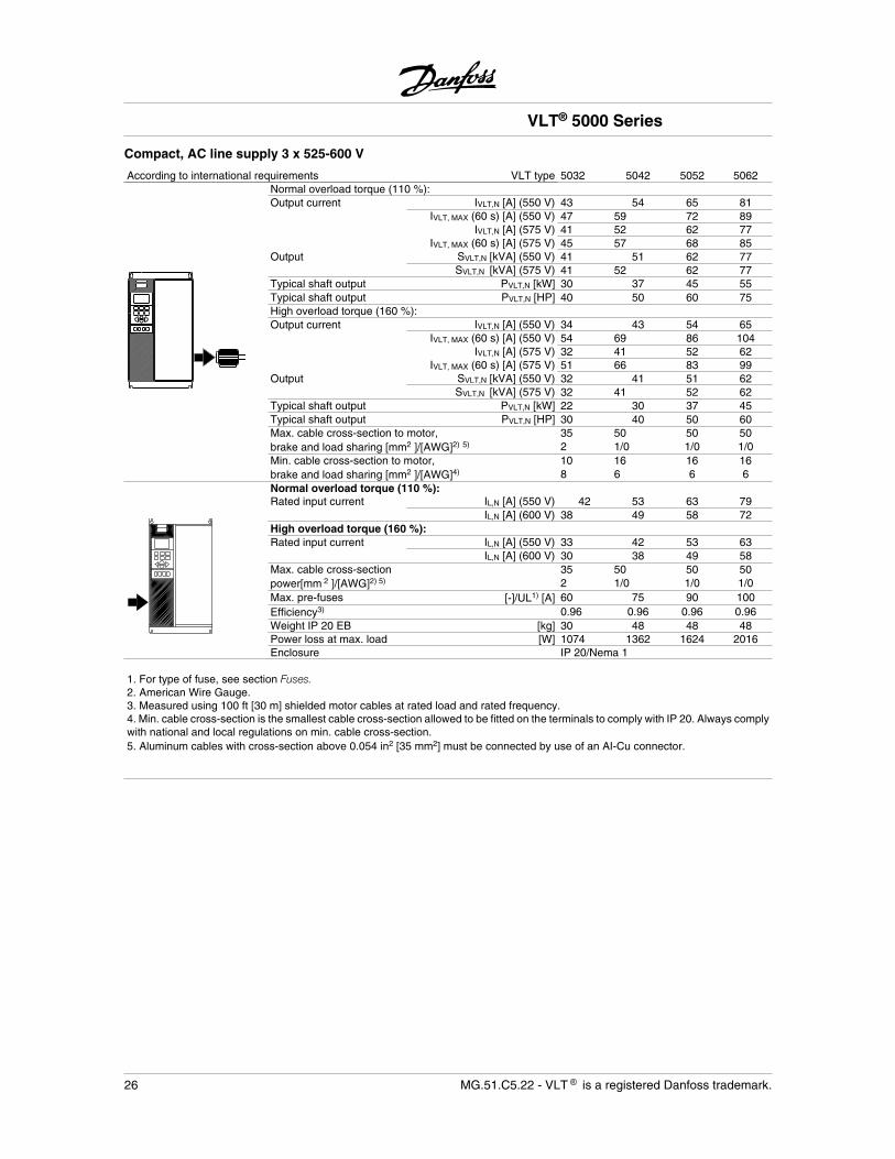
Compact, AC line supply 3 x 525-600 V
According to international requirements VLT type 5032 5042 5052 5062Normal overload torque (110 %):Output current IVLT,N [A] (550 V) 43 54 65 81
IVLT, MAX (60 s) [A] (550 V) 47 59 72 89IVLT,N [A] (575 V) 41 52 62 77
IVLT, MAX (60 s) [A] (575 V) 45 57 68 85Output SVLT,N [kVA] (550 V) 41 51 62 77
SVLT,N [kVA] (575 V) 41 52 62 77Typical shaft output PVLT,N [kW] 30 37 45 55Typical shaft output PVLT,N [HP] 40 50 60 75High overload torque (160 %): Output current IVLT,N [A] (550 V) 34 43 54 65
IVLT, MAX (60 s) [A] (550 V) 54 69 86 104IVLT,N [A] (575 V) 32 41 52 62
IVLT, MAX (60 s) [A] (575 V) 51 66 83 99Output SVLT,N [kVA] (550 V) 32 41 51 62
SVLT,N [kVA] (575 V) 32 41 52 62Typical shaft output PVLT,N [kW] 22 30 37 45Typical shaft output PVLT,N [HP] 30 40 50 60Max. cable cross-section to motor, 35 50 50 50brake and load sharing [mm2 ]/[AWG]2) 5) 2 1/0 1/0 1/0Min. cable cross-section to motor, 10 16 16 16brake and load sharing [mm2 ]/[AWG]4) 8 6 6 6Normal overload torque (110 %): Rated input current IL,N [A] (550 V) 42 53 63 79
IL,N [A] (600 V) 38 49 58 72High overload torque (160 %):Rated input current IL,N [A] (550 V) 33 42 53 63
IL,N [A] (600 V) 30 38 49 58Max. cable cross-section 35 50 50 50power[mm 2 ]/[AWG]2) 5) 2 1/0 1/0 1/0Max. pre-fuses [-]/UL1) [A] 60 75 90 100Efficiency3) 0.96 0.96 0.96 0.96Weight IP 20 EB [kg] 30 48 48 48Power loss at max. load [W] 1074 1362 1624 2016Enclosure IP 20/Nema 1
1. For type of fuse, see section Fuses.2. American Wire Gauge.3. Measured using 100 ft [30 m] shielded motor cables at rated load and rated frequency.4. Min. cable cross-section is the smallest cable cross-section allowed to be fitted on the terminals to comply with IP 20. Always complywith national and local regulations on min. cable cross-section.5. Aluminum cables with cross-section above 0.054 in2 [35 mm2] must be connected by use of an AI-Cu connector.
VLT® 5000 Series
26 MG.51.C5.22 - VLT is a registered Danfoss trademark.
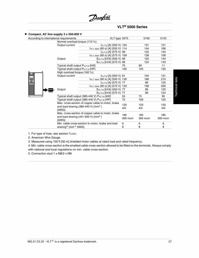
Compact, AC line supply 3 x 550-600 VAccording to international requirements VLT type 5075 5100 5125
Normal overload torque (110 %):Output current IVLT,N [A] (550 V) 104 131 151
IVLT, MAX (60 s) [A] (550 V) 114 144 166IVLT,N [A] (575 V) 99 125 144
IVLT, MAX (60 s) [A] (575 V) 109 138 158Output SVLT,N [kVA] (550 V) 99 125 144
SVLT,N [kVA] (575 V) 99 124 143Typical shaft output PVLT,N [kW] 75 90 11Typical shaft output PVLT,N [HP] 100 125 150High overload torque (160 %): Output current IVLT,N [A] (550 V) 81 104 131
IVLT, MAX (60 s) [A] (550 V) 130 166 210IVLT,N [A] (575 V) 77 99 125
IVLT, MAX (60 s) [A] (575 V) 123 158 200Output SVLT,N [kVA] (550 V) 77 99 125
SVLT,N [kVA] (575 V) 77 99 124Typical shaft output (380-440 V) PVLT,N [kW] 55 75 90Typical shaft output (380-440 V) PVLT,N [HP] 75 100 125Max. cross-section of copper cable to motor, brakeand load sharing (380-440 V) [mm2 ][AWG]
1204/0
1204/0
1204/0
Max. cross-section of copper cable to motor, brakeand load sharing (441-500 V) [mm2 ][AWG]
185300 mcm
185300 mcm
185300 mcm
Min. cable cross-section to motor, brake and loadsharing4) [mm 2/ AWG]
68
68
68
1. For type of fuse, see section Fuses.2. American Wire Gauge.3. Measured using 100 ft [30 m] shielded motor cables at rated load and rated frequency.4. Min. cable cross-section is the smallest cable cross-section allowed to be fitted on the terminals. Always complywith national and local regulations on min. cable cross-section.5. Connection stud 1 x M8/2 x M8.
VLT® 5000 Series
MG.51.C5.22 - VLT is a registered Danfoss trademark. 27
Tec
hnic
al d
ata
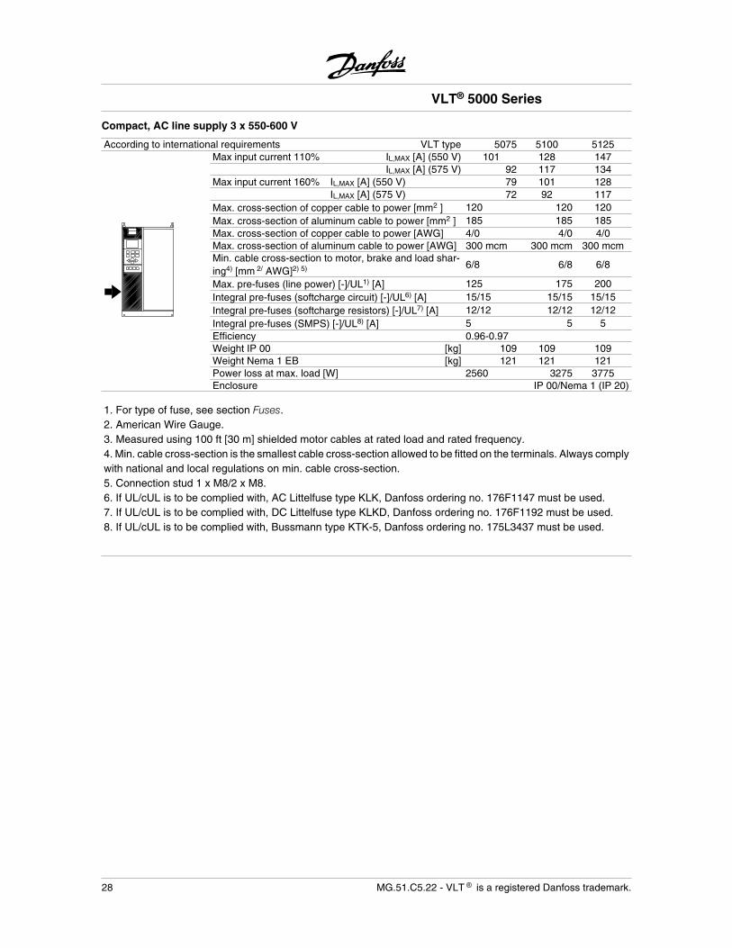
Compact, AC line supply 3 x 550-600 V
According to international requirements VLT type 5075 5100 5125Max input current 110% IL,MAX [A] (550 V) 101 128 147
IL,MAX [A] (575 V) 92 117 134Max input current 160% IL,MAX [A] (550 V) 79 101 128
IL,MAX [A] (575 V) 72 92 117Max. cross-section of copper cable to power [mm2 ] 120 120 120Max. cross-section of aluminum cable to power [mm2 ] 185 185 185Max. cross-section of copper cable to power [AWG] 4/0 4/0 4/0Max. cross-section of aluminum cable to power [AWG] 300 mcm 300 mcm 300 mcmMin. cable cross-section to motor, brake and load shar-ing4) [mm 2/ AWG]2) 5) 6/8 6/8 6/8
Max. pre-fuses (line power) [-]/UL1) [A] 125 175 200Integral pre-fuses (softcharge circuit) [-]/UL6) [A] 15/15 15/15 15/15Integral pre-fuses (softcharge resistors) [-]/UL7) [A] 12/12 12/12 12/12Integral pre-fuses (SMPS) [-]/UL8) [A] 5 5 5Efficiency 0.96-0.97Weight IP 00 [kg] 109 109 109Weight Nema 1 EB [kg] 121 121 121Power loss at max. load [W] 2560 3275 3775Enclosure IP 00/Nema 1 (IP 20)
1. For type of fuse, see section Fuses.2. American Wire Gauge.3. Measured using 100 ft [30 m] shielded motor cables at rated load and rated frequency.4. Min. cable cross-section is the smallest cable cross-section allowed to be fitted on the terminals. Always complywith national and local regulations on min. cable cross-section.5. Connection stud 1 x M8/2 x M8.6. If UL/cUL is to be complied with, AC Littelfuse type KLK, Danfoss ordering no. 176F1147 must be used.7. If UL/cUL is to be complied with, DC Littelfuse type KLKD, Danfoss ordering no. 176F1192 must be used.8. If UL/cUL is to be complied with, Bussmann type KTK-5, Danfoss ordering no. 175L3437 must be used.
VLT® 5000 Series
28 MG.51.C5.22 - VLT is a registered Danfoss trademark.
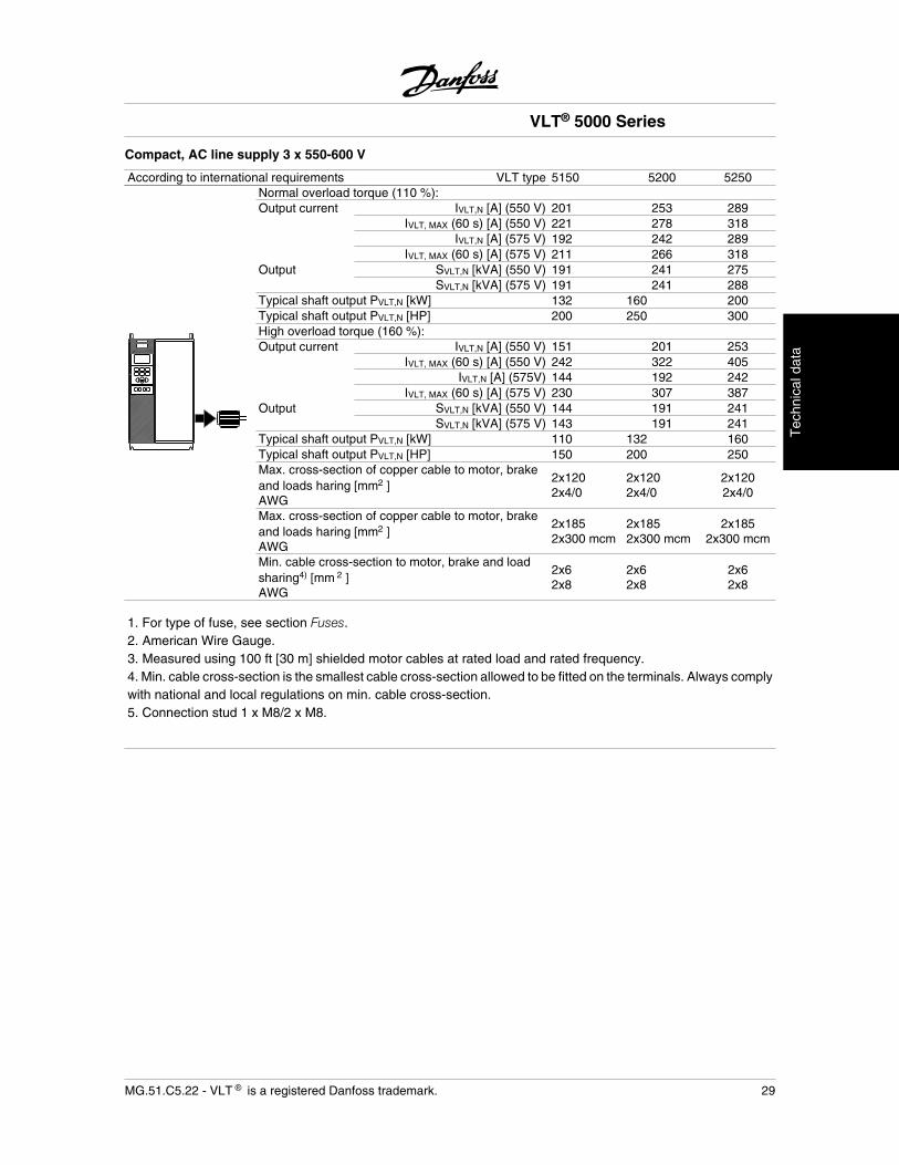
Compact, AC line supply 3 x 550-600 V
According to international requirements VLT type 5150 5200 5250Normal overload torque (110 %):Output current IVLT,N [A] (550 V) 201 253 289
IVLT, MAX (60 s) [A] (550 V) 221 278 318IVLT,N [A] (575 V) 192 242 289
IVLT, MAX (60 s) [A] (575 V) 211 266 318Output SVLT,N [kVA] (550 V) 191 241 275
SVLT,N [kVA] (575 V) 191 241 288Typical shaft output PVLT,N [kW] 132 160 200Typical shaft output PVLT,N [HP] 200 250 300High overload torque (160 %): Output current IVLT,N [A] (550 V) 151 201 253
IVLT, MAX (60 s) [A] (550 V) 242 322 405IVLT,N [A] (575V) 144 192 242
IVLT, MAX (60 s) [A] (575 V) 230 307 387Output SVLT,N [kVA] (550 V) 144 191 241
SVLT,N [kVA] (575 V) 143 191 241Typical shaft output PVLT,N [kW] 110 132 160Typical shaft output PVLT,N [HP] 150 200 250Max. cross-section of copper cable to motor, brakeand loads haring [mm2 ]AWG
2x1202x4/0
2x1202x4/0
2x1202x4/0
Max. cross-section of copper cable to motor, brakeand loads haring [mm2 ]AWG
2x1852x300 mcm
2x1852x300 mcm
2x1852x300 mcm
Min. cable cross-section to motor, brake and loadsharing4) [mm 2 ]AWG
2x62x8
2x62x8
2x62x8
1. For type of fuse, see section Fuses.2. American Wire Gauge.3. Measured using 100 ft [30 m] shielded motor cables at rated load and rated frequency.4. Min. cable cross-section is the smallest cable cross-section allowed to be fitted on the terminals. Always complywith national and local regulations on min. cable cross-section.5. Connection stud 1 x M8/2 x M8.
VLT® 5000 Series
MG.51.C5.22 - VLT is a registered Danfoss trademark. 29
Tec
hnic
al d
ata
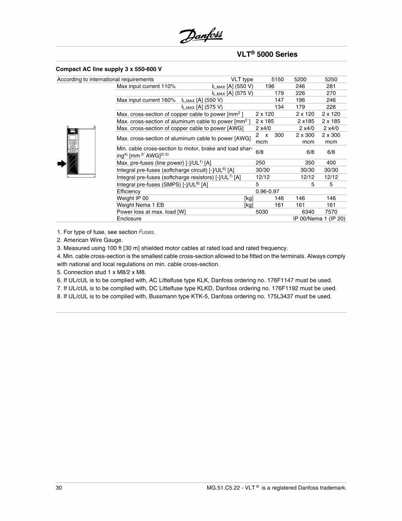
Compact AC line supply 3 x 550-600 V
According to international requirements VLT type 5150 5200 5250Max input current 110% IL,MAX [A] (550 V) 196 246 281
IL,MAX [A] (575 V) 179 226 270Max input current 160% IL,MAX [A] (550 V) 147 196 246
IL,MAX [A] (575 V) 134 179 226Max. cross-section of copper cable to power [mm2 ] 2 x 120 2 x 120 2 x 120Max. cross-section of aluminum cable to power [mm2 ] 2 x 185 2 x185 2 x 185Max. cross-section of copper cable to power [AWG] 2 x4/0 2 x4/0 2 x4/0
Max. cross-section of aluminum cable to power [AWG]2 x 300mcm
2 x 300mcm
2 x 300mcm
Min. cable cross-section to motor, brake and load shar-ing4) [mm 2/ AWG]2) 5) 6/8 6/8 6/8
Max. pre-fuses (line power) [-]/UL1) [A] 250 350 400Integral pre-fuses (softcharge circuit) [-]/UL6) [A] 30/30 30/30 30/30Integral pre-fuses (softcharge resistors) [-]/UL7) [A] 12/12 12/12 12/12Integral pre-fuses (SMPS) [-]/UL8) [A] 5 5 5Efficiency 0.96-0.97Weight IP 00 [kg] 146 146 146Weight Nema 1 EB [kg] 161 161 161Power loss at max. load [W] 5030 6340 7570Enclosure IP 00/Nema 1 (IP 20)
1. For type of fuse, see section Fuses.2. American Wire Gauge.3. Measured using 100 ft [30 m] shielded motor cables at rated load and rated frequency.4. Min. cable cross-section is the smallest cable cross-section allowed to be fitted on the terminals. Always complywith national and local regulations on min. cable cross-section.5. Connection stud 1 x M8/2 x M8.6. If UL/cUL is to be complied with, AC Littelfuse type KLK, Danfoss ordering no. 176F1147 must be used.7. If UL/cUL is to be complied with, DC Littelfuse type KLKD, Danfoss ordering no. 176F1192 must be used.8. If UL/cUL is to be complied with, Bussmann type KTK-5, Danfoss ordering no. 175L3437 must be used.
VLT® 5000 Series
30 MG.51.C5.22 - VLT is a registered Danfoss trademark.
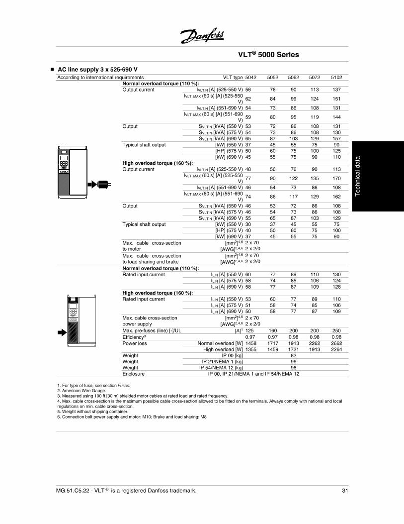
AC line supply 3 x 525-690 VAccording to international requirements VLT type 5042 5052 5062 5072 5102
Normal overload torque (110 %):Output current IVLT,N [A] (525-550 V) 56 76 90 113 137
IVLT, MAX (60 s) [A] (525-550V)
62 84 99 124 151
IVLT,N [A] (551-690 V) 54 73 86 108 131IVLT, MAX (60 s) [A] (551-690
V)59 80 95 119 144
Output SVLT,N [kVA] (550 V) 53 72 86 108 131SVLT,N [kVA] (575 V) 54 73 86 108 130SVLT,N [kVA] (690 V) 65 87 103 129 157
Typical shaft output [kW] (550 V) 37 45 55 75 90 [HP] (575 V) 50 60 75 100 125
[kW] (690 V) 45 55 75 90 110High overload torque (160 %):Output current IVLT,N [A] (525-550 V) 48 56 76 90 113
IVLT, MAX (60 s) [A] (525-550V)
77 90 122 135 170
IVLT,N [A] (551-690 V) 46 54 73 86 108IVLT, MAX (60 s) [A] (551-690
V)74 86 117 129 162
Output SVLT,N [kVA] (550 V) 46 53 72 86 108SVLT,N [kVA] (575 V) 46 54 73 86 108SVLT,N [kVA] (690 V) 55 65 87 103 129
Typical shaft output [kW] (550 V) 30 37 45 55 75 [HP] (575 V) 40 50 60 75 100
[kW] (690 V) 37 45 55 75 90Max. cable cross-sectionto motor
[mm2]4,6
[AWG]2,4,6
2 x 702 x 2/0
Max. cable cross-sectionto load sharing and brake
[mm2]4,6
[AWG]2,4,6
2 x 702 x 2/0
Normal overload torque (110 %):Rated input current IL,N [A] (550 V) 60 77 89 110 130
IL,N [A] (575 V) 58 74 85 106 124IL,N [A] (690 V) 58 77 87 109 128
High overload torque (160 %):Rated input current IL,N [A] (550 V) 53 60 77 89 110
IL,N [A] (575 V) 51 58 74 85 106IL,N [A] (690 V) 50 58 77 87 109
Max. cable cross-sectionpower supply
[mm2]4,6
[AWG]2,4,62 x 702 x 2/0
Max. pre-fuses (line) [-]/UL [A]1 125 160 200 200 250Efficiency3 0.97 0.97 0.98 0.98 0.98Power loss Normal overload [W] 1458 1717 1913 2262 2662
High overload [W] 1355 1459 1721 1913 2264Weight IP 00 [kg] 82Weight IP 21/NEMA 1 [kg] 96Weight IP 54/NEMA 12 [kg] 96Enclosure IP 00, IP 21/NEMA 1 and IP 54/NEMA 12
1. For type of fuse, see section Fuses.2. American Wire Gauge.3. Measured using 100 ft [30 m] shielded motor cables at rated load and rated frequency.4. Max. cable cross-section is the maximum possible cable cross-section allowed to be fitted on the terminals. Always comply with national and localregulations on min. cable cross-section.5. Weight without shipping container.6. Connection bolt power supply and motor: M10; Brake and load sharing: M8
VLT® 5000 Series
MG.51.C5.22 - VLT is a registered Danfoss trademark. 31
Tec
hnic
al d
ata
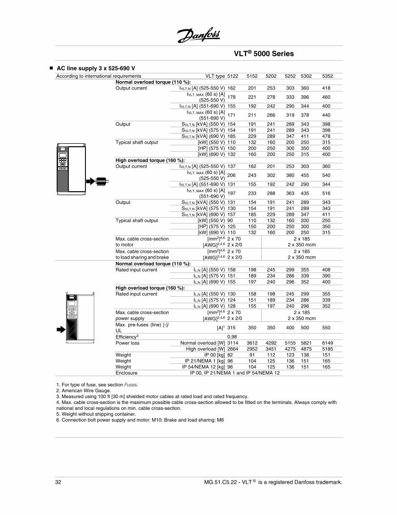
AC line supply 3 x 525-690 VAccording to international requirements VLT type 5122 5152 5202 5252 5302 5352
Normal overload torque (110 %):Output current IVLT,N [A] (525-550 V) 162 201 253 303 360 418
IVLT, MAX (60 s) [A](525-550 V)
178 221 278 333 396 460
IVLT,N [A] (551-690 V) 155 192 242 290 344 400IVLT, MAX (60 s) [A]
(551-690 V)171 211 266 319 378 440
Output SVLT,N [kVA] (550 V) 154 191 241 289 343 398SVLT,N [kVA] (575 V) 154 191 241 289 343 398SVLT,N [kVA] (690 V) 185 229 289 347 411 478
Typical shaft output [kW] (550 V) 110 132 160 200 250 315 [HP] (575 V) 150 200 250 300 350 400
[kW] (690 V) 132 160 200 250 315 400High overload torque (160 %):Output current IVLT,N [A] (525-550 V) 137 162 201 253 303 360
IVLT, MAX (60 s) [A](525-550 V)
206 243 302 380 455 540
IVLT,N [A] (551-690 V) 131 155 192 242 290 344IVLT, MAX (60 s) [A]
(551-690 V)197 233 288 363 435 516
Output SVLT,N [kVA] (550 V) 131 154 191 241 289 343SVLT,N [kVA] (575 V) 130 154 191 241 289 343SVLT,N [kVA] (690 V) 157 185 229 289 347 411
Typical shaft output [kW] (550 V) 90 110 132 160 200 250 [HP] (575 V) 125 150 200 250 300 350
[kW] (690 V) 110 132 160 200 250 315Max. cable cross-sectionto motor
[mm2]4,6
[AWG]2,4,62 x 702 x 2/0
2 x 1852 x 350 mcm
Max. cable cross-sectionto load sharing and brake
[mm2]4,6
[AWG]2,4,62 x 702 x 2/0
2 x 1852 x 350 mcm
Normal overload torque (110 %):Rated input current IL,N [A] (550 V) 158 198 245 299 355 408
IL,N [A] (575 V) 151 189 234 286 339 390IL,N [A] (690 V) 155 197 240 296 352 400
High overload torque (160 %):Rated input current IL,N [A] (550 V) 130 158 198 245 299 355
IL,N [A] (575 V) 124 151 189 234 286 339IL,N [A] (690 V) 128 155 197 240 296 352
Max. cable cross-sectionpower supply
[mm2]4,6
[AWG]2,4,62 x 702 x 2/0
2 x 1852 x 350 mcm
Max. pre-fuses (line) [-]/UL [A]1 315 350 350 400 500 550
Efficiency3 0,98Power loss Normal overload [W] 3114 3612 4292 5155 5821 6149
High overload [W] 2664 2952 3451 4275 4875 5185Weight IP 00 [kg] 82 91 112 123 138 151Weight IP 21/NEMA 1 [kg] 96 104 125 136 151 165Weight IP 54/NEMA 12 [kg] 96 104 125 136 151 165Enclosure IP 00, IP 21/NEMA 1 and IP 54/NEMA 12
1. For type of fuse, see section Fuses.2. American Wire Gauge.3. Measured using 100 ft [30 m] shielded motor cables at rated load and rated frequency.4. Max. cable cross-section is the maximum possible cable cross-section allowed to be fitted on the terminals. Always comply withnational and local regulations on min. cable cross-section.5. Weight without shipping container.6. Connection bolt power supply and motor: M10; Brake and load sharing: M8
VLT® 5000 Series
32 MG.51.C5.22 - VLT is a registered Danfoss trademark.
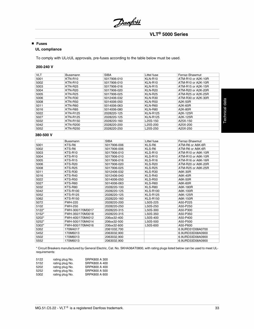
Fuses
UL compliance
To comply with UL/cUL approvals, pre-fuses according to the table below must be used.
200-240 V
VLT Bussmann SIBA Littel fuse Ferraz-Shawmut5001 KTN-R10 5017906-010 KLN-R10 ATM-R10 or A2K-10R5002 KTN-R10 5017906-010 KLN-R10 ATM-R10 or A2K-10R5003 KTN-R25 5017906-016 KLN-R15 ATM-R15 or A2K-15R5004 KTN-R20 5017906-020 KLN-R20 ATM-R20 or A2K-20R5005 KTN-R25 5017906-025 KLN-R25 ATM-R25 or A2K-25R5006 KTN-R30 5012406-032 KLN-R30 ATM-R30 or A2K-30R5008 KTN-R50 5014006-050 KLN-R50 A2K-50R5011 KTN-R60 5014006-063 KLN-R60 A2K-60R5016 KTN-R85 5014006-080 KLN-R80 A2K-80R5022 KTN-R125 2028220-125 KLN-R125 A2K-125R5027 KTN-R125 2028220-125 KLN-R125 A2K-125R5032 KTN-R150 2028220-160 L25S-150 A25X-1505042 KTN-R200 2028220-200 L25S-200 A25X-2005052 KTN-R250 2028220-250 L25S-250 A25X-250
380-500 V
Bussmann SIBA Littel fuse Ferraz-Shawmut5001 KTS-R6 5017906-006 KLS-R6 ATM-R6 or A6K-6R5002 KTS-R6 5017906-006 KLS-R6 ATM-R6 or A6K-6R5003 KTS-R10 5017906-010 KLS-R10 ATM-R10 or A6K-10R5004 KTS-R10 5017906-010 KLS-R10 ATM-R10 or A6K-10R5005 KTS-R15 5017906-016 KLS-R16 ATM-R16 or A6K-16R5006 KTS-R20 5017906-020 KLS-R20 ATM-R20 or A6K-20R5008 KTS-R25 5017906-025 KLS-R25 ATM-R25 or A6K-25R5011 KTS-R30 5012406-032 KLS-R30 A6K-30R5016 KTS-R40 5012406-040 KLS-R40 A6K-40R5022 KTS-R50 5014006-050 KLS-R50 A6K-50R5027 KTS-R60 5014006-063 KLS-R60 A6K-60R5032 KTS-R80 2028220-100 KLS-R80 A6K-180R5042 KTS-R100 2028220-125 KLS-R100 A6K-100R5052 KTS-R125 2028220-125 KLS-R125 A6K-125R5062 KTS-R150 2028220-160 KLS-R150 A6K-150R5072 FWH-220 2028220-200 L50S-225 A50-P2255102 FWH-250 2028220-250 L50S-250 A50-P2505122* FWH-300/170M3017 2028220-315 L50S-300 A50-P3005152* FWH-350/170M3018 2028220-315 L50S-350 A50-P3505202* FWH-400/170M4012 206xx32-400 L50S-400 A50-P4005252* FWH-500/170M4014 206xx32-500 L50S-500 A50-P5005302* FWH-600/170M4016 206xx32-600 L50S-600 A50-P6005352 170M4017 2061032,700 6.9URD31D08A07005452 170M6013 2063032,900 6.9URD33D08A09005502 170M6013 2063032,900 6.9URD33D08A09005552 170M6013 2063032,900 6.9URD33D08A0900
* Circuit Breakers manufactured by General Electric, Cat. No. SKHA36AT0800, with rating plugs listed below can be used to meet UL-requirements: 5122 rating plug No. SRPK800 A 3005152 rating plug No. SRPK800 A 4005202 rating plug No. SRPK800 A 4005252 rating plug No. SRPK800 A 5005302 rating plug No. SRPK800 A 600
VLT® 5000 Series
MG.51.C5.22 - VLT is a registered Danfoss trademark. 33
Tec
hnic
al d
ata
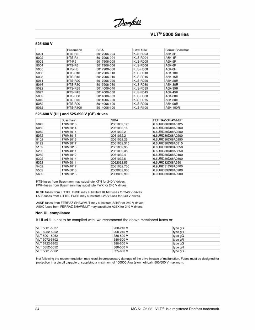
525-600 V
Bussmann SIBA Littel fuse Ferraz-Shawmut5001 KTS-R3 5017906-004 KLS-R003 A6K-3R5002 KTS-R4 5017906-004 KLS-R004 A6K-4R5003 KT-R5 5017906-005 KLS-R005 A6K-5R5004 KTS-R6 5017906-006 KLS-R006 A6K-6R5005 KTS-R8 5017906-008 KLS-R008 A6K-8R5006 KTS-R10 5017906-010 KLS-R010 A6K-10R5008 KTS-R15 5017906-016 KLS-R015 A6K-15R5011 KTS-R20 5017906-020 KLS-R020 A6K-20R5016 KTS-R30 5017906-030 KLS-R030 A6K-30R5022 KTS-R35 5014006-040 KLS-R035 A6K-35R5027 KTS-R45 5014006-050 KLS-R045 A6K-45R5032 KTS-R60 5014006-063 KLS-R060 A6K-60R5042 KTS-R75 5014006-080 KLS-R075 A6K-80R5052 KTS-R90 5014006-100 KLS-R090 A6K-90R5062 KTS-R100 5014006-100 KLS-R100 A6K-100R
525-600 V (UL) and 525-690 V (CE) drives
Bussmann SIBA FERRAZ-SHAWMUT5042 170M3013 2061032,125 6.6URD30D08A01255052 170M3014 2061032,16 6.6URD30D08A01605062 170M3015 2061032,2 6.6URD30D08A02005072 170M3015 2061032,2 6.6URD30D08A02005102 170M3016 2061032,25 6.6URD30D08A02505122 170M3017 2061032,315 6.6URD30D08A03155152 170M3018 2061032,35 6.6URD30D08A03505202 170M4011 2061032,35 6.6URD30D08A03505252 170M4012 2061032,4 6.6URD30D08A04005302 170M4014 2061032,5 6.6URD30D08A05005352 170M5011 2062032,55 6.6URD32D08A5505402 170M4017 2061032,700 6.9URD31D08A07005502 170M6013 2063032,900 6.9URD33D08A09005602 170M6013 2063032,900 6.9URD33D08A0900
KTS-fuses from Bussmann may substitute KTN for 240 V drives.FWH-fuses from Bussmann may substitute FWX for 240 V drives.
KLSR fuses from LITTEL FUSE may substitute KLNR fuses for 240 V drives.L50S fuses from LITTEL FUSE may substitute L25S fuses for 240 V drives.
A6KR fuses from FERRAZ SHAWMUT may substitute A2KR for 240 V drives.A50X fuses from FERRAZ SHAWMUT may substitute A25X for 240 V drives.
Non UL compliance
If UL/cUL is not to be complied with, we recommend the above mentioned fuses or:
VLT 5001-5027 200-240 V type gGVLT 5032-5052 200-240 V type gRVLT 5001-5062 380-500 V type gGVLT 5072-5102 380-500 V type gRVLT 5122-5302 380-500 V type gGVLT 5352-5552 380-500 V type gRVLT 5001-5062 525-600 V type gG
Not following the recommendation may result in unnecessary damage of the drive in case of malfunction. Fuses must be designed forprotection in a circuit capable of supplying a maximum of 100000 Arms (symmetrical), 500/600 V maximum.
VLT® 5000 Series
34 MG.51.C5.22 - VLT is a registered Danfoss trademark.

Brake resistors, VLT 5001 - 5052 / 200 - 240 V
Standard brake resistors10% duty cycle 40% duty cycle
VLTResistance[ohm]
Power[kW]
Code No. Resistance[ohm]
Power[kW]
Code No.
5001 145 0.065 175U1820 145 0.260 175U19205002 90 0.095 175U1821 90 0.430 175U19215003 65 0.250 175U1822 65 0.80 175U19225004 50 0.285 175U1823 50 1.00 175U19235005 35 0.430 175U1824 35 1.35 175U19245006 25 0.8 175U1825 25 3.00 175U19255008 20 1.0 175U1826 20 3.50 175U19265011 15 1.8 175U1827 15 5.00 175U19275016 10 2.8 175U1828 10 9.0 175U19285022 7 4.0 175U1829 7 10.0 175U19295027 6 4.8 175U1830 6 12.7 175U19305032 4.7 6 175U1954 Not available Not available Not available5042 3.3 8 175U1955 Not available Not available Not available5052 2.7 10 175U1956 Not available Not available Not available
See Instruction MI.90.FX.YY for further information.
Flatpack brake resistors for horizontal conveyorsVLT type Motor [kW] Resistor [ohm] Size Order number Max. duty cycle [%]5001 0.75 150 150 100 W 175U1005 14.05001 0.75 150 150 200 W 175U0989 40.05002 1.1 100 100 100 W 175U1006 8.05002 1.1 100 100 200 W 175U0991 20.05003 1.5 72 72 200 W 175U0992 16.05004 2.2 47 50 200 W 175U0993 9.05005 3 35 35 200 W 175U0994 5.55005 3 35 72 200 W 2 x 175U09921 12.05006 4 25 50 200 W 2 x 175U09931 11.05008 5.5 20 40 200 W 2 x 175U09961 6.55011 7.5 13 27 200 W 2 x 175U09951 4.0
1. Order 2 pcs.Mounting angle for flatpack resistor 100 W 175U0011Mounting angle for flatpack resistor 200 W 175U0009Mounting frame for 1 resistor narrow (slim bookstyle)175U0002Mounting frame for 2 resistors narrow (slim bookstyle)175U0004
Mounting frame for 2 resistors broad (wide bookstyle)175U0003
See Instruction MI.50.BX.YY for further information.
VLT® 5000 Series
MG.51.C5.22 - VLT is a registered Danfoss trademark. 35
Tec
hnic
al d
ata
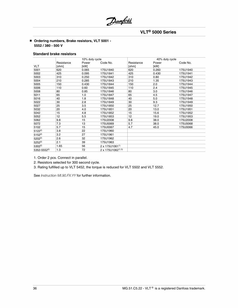
Ordering numbers, Brake resistors, VLT 5001 -5552 / 380 - 500 V
Standard brake resistors10% duty cycle 40% duty cycle
VLTResistance[ohm]
Power[kW]
Code No. Resistance[ohm]
Power[kW]
Code No.
5001 620 0.065 175U1840 620 0.260 175U19405002 425 0.095 175U1841 425 0.430 175U19415003 310 0.250 175U1842 310 0.80 175U19425004 210 0.285 175U1843 210 1.35 175U19435005 150 0.430 175U1844 150 2.0 175U19445006 110 0.60 175U1845 110 2.4 175U19455008 80 0.85 175U1846 80 3.0 175U19465011 65 1.0 175U1847 65 4.5 175U19475016 40 1.8 175U1848 40 5.0 175U19485022 30 2.8 175U1849 30 9.3 175U19495027 25 3.5 175U1850 25 12.7 175U19505032 20 4.0 175U1851 20 13.0 175U19515042 15 4.8 175U1852 15 15.6 175U19525052 12 5.5 175U1853 12 19.0 175U19535062 9.8 15 175U2008 9.8 38.0 175U20085072 7.3 13 175U0069 5.7 38.0 175U00685102 5.7 15 175U0067 4.7 45.0 175U006651222) 3.8 22 175U196051522) 3.2 27 175U196152022) 2.6 32 175U196252522) 2.1 39 175U196353022) 1.65 56 2 x 175U10611)
5352-55522) 1.3 72 2 x 175U10621) 3)
1. Order 2 pcs. Connect in parallel.2. Resistors selected for 300 second cycle.3. Rating fulfilled up to VLT 5452, the torque is reduced for VLT 5502 and VLT 5552.
See Instruction MI.90.FX.YY for further information.
VLT® 5000 Series
36 MG.51.C5.22 - VLT is a registered Danfoss trademark.

Flatpack brake resistors for horizontal conveyorsVLT type Motor [kW] Resistor [ohm] Size Order number Max. duty cycle [%]5001 0.75 630 620 100 W 175U1001 14.05001 0.75 630 620 200 W 175U0982 40.05002 1.1 430 430 100 W 175U1002 8.05002 1.1 430 430 200 W 175U0983 20.05003 1.5 320 310 200 W 175U0984 16.05004 2.2 215 210 200 W 175U0987 9.05005 3 150 150 200 W 175U0989 5.55005 3 150 300 200 W 2 x 175U09851 12.05006 4 120 240 200 W 2 x 175U09861 11.05008 5.5 82 160 200 W 2 x 175U09881 6.55011 7.5 65 130 200 W 2 x 175U09901 4.0
1. Order 2 pcs.Mounting angle for flatpack resistor 100 W 175U0011.Mounting angle for flatpack resistor 200 W 175U0009.Mounting frame for 1 resistor narrow (slim bookstyle) 175U0002.Mounting frame for 2 resistors narrow (slim bookstyle) 175U0004.Mounting frame for 2 resistors broad (wide bookstyle) 175U0003.See Instruction MI.50.BX.YY for further information.For 525-600 V and 525-690 V please contact Danfoss.
VLT® 5000 Series
MG.51.C5.22 - VLT is a registered Danfoss trademark. 37
Tec
hnic
al d
ata
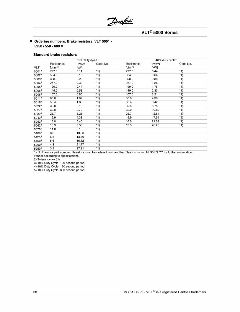
Ordering numbers, Brake resistors, VLT 5001 -5250 / 550 - 600 V
Standard brake resistors10% duty cycle 40% duty cycle4
VLTResistance[ohm]2
Power[kW]
Code No. Resistance[ohm]2
Power[kW]
Code No.
50013 797.0 0.11 *1) 797.0 0.44 *1)50023 534.0 0.16 *1) 534.0 0.64 *1)50033 398.0 0.22 *1) 398.0 0.88 *1)50043 267.0 0.32 *1) 267.0 1.28 *1)50053 199.0 0.44 *1) 199.0 1.75 *1)50063 149.0 0.58 *1) 149.0 2.33 *1)50083 107.0 0.80 *1) 107.0 3.21 *1)50113 80.0 1.09 *1) 80.0 4.38 *1)50163 53.4 1.60 *1) 53.4 6.42 *1)50223 39.8 2.19 *1) 39.8 8.75 *1)50273 32.0 2.70 *1) 32.0 10.80 *1)50323 26.7 3.21 *1) 26.7 12.84 *1)50423 19.9 4.38 *1) 19.9 17.51 *1)50523 16.0 5.40 *1) 16.0 21.59 *1)50623 13.3 6.56 *1) 13.3 26.26 *1)50755 11.0 8.16 *1)51005 8.2 10.88 *1)51255 6.8 13.60 *1)51505 5.6 16.32 *1)52005 4.3 21.77 *1)52505 3.3 27.21 *1)1) No Danfoss part number. Resistors must be ordered from anothervendor according to specifications.2) Tolerance +/- 5%3) 10% Duty Cycle, 120 second period4) 40% Duty Cycle, 120 second period5) 10% Duty Cycle, 300 second period
See instruction MI.90.FX.YY for further information.
VLT® 5000 Series
38 MG.51.C5.22 - VLT is a registered Danfoss trademark.
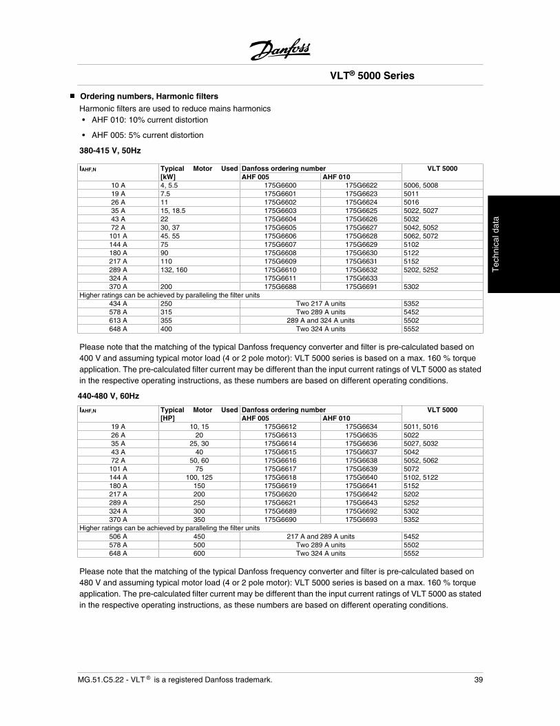
Ordering numbers, Harmonic filters
Harmonic filters are used to reduce mains harmonics• AHF 010: 10% current distortion
• AHF 005: 5% current distortion
380-415 V, 50Hz
IAHF,N Typical Motor Used[kW]
Danfoss ordering number VLT 5000AHF 005 AHF 010
10 A 4, 5.5 175G6600 175G6622 5006, 500819 A 7.5 175G6601 175G6623 501126 A 11 175G6602 175G6624 501635 A 15, 18.5 175G6603 175G6625 5022, 502743 A 22 175G6604 175G6626 503272 A 30, 37 175G6605 175G6627 5042, 5052101 A 45. 55 175G6606 175G6628 5062, 5072144 A 75 175G6607 175G6629 5102180 A 90 175G6608 175G6630 5122217 A 110 175G6609 175G6631 5152289 A 132, 160 175G6610 175G6632 5202, 5252324 A 175G6611 175G6633370 A 200 175G6688 175G6691 5302
Higher ratings can be achieved by paralleling the filter units434 A 250 Two 217 A units 5352578 A 315 Two 289 A units 5452613 A 355 289 A and 324 A units 5502648 A 400 Two 324 A units 5552
Please note that the matching of the typical Danfoss frequency converter and filter is pre-calculated based on400 V and assuming typical motor load (4 or 2 pole motor): VLT 5000 series is based on a max. 160 % torqueapplication. The pre-calculated filter current may be different than the input current ratings of VLT 5000 as statedin the respective operating instructions, as these numbers are based on different operating conditions.
440-480 V, 60Hz
IAHF,N Typical Motor Used[HP]
Danfoss ordering number VLT 5000AHF 005 AHF 010
19 A 10, 15 175G6612 175G6634 5011, 501626 A 20 175G6613 175G6635 502235 A 25, 30 175G6614 175G6636 5027, 503243 A 40 175G6615 175G6637 504272 A 50, 60 175G6616 175G6638 5052, 5062101 A 75 175G6617 175G6639 5072144 A 100, 125 175G6618 175G6640 5102, 5122180 A 150 175G6619 175G6641 5152217 A 200 175G6620 175G6642 5202289 A 250 175G6621 175G6643 5252324 A 300 175G6689 175G6692 5302370 A 350 175G6690 175G6693 5352
Higher ratings can be achieved by paralleling the filter units506 A 450 217 A and 289 A units 5452578 A 500 Two 289 A units 5502648 A 600 Two 324 A units 5552
Please note that the matching of the typical Danfoss frequency converter and filter is pre-calculated based on480 V and assuming typical motor load (4 or 2 pole motor): VLT 5000 series is based on a max. 160 % torqueapplication. The pre-calculated filter current may be different than the input current ratings of VLT 5000 as statedin the respective operating instructions, as these numbers are based on different operating conditions.
VLT® 5000 Series
MG.51.C5.22 - VLT is a registered Danfoss trademark. 39
Tec
hnic
al d
ata
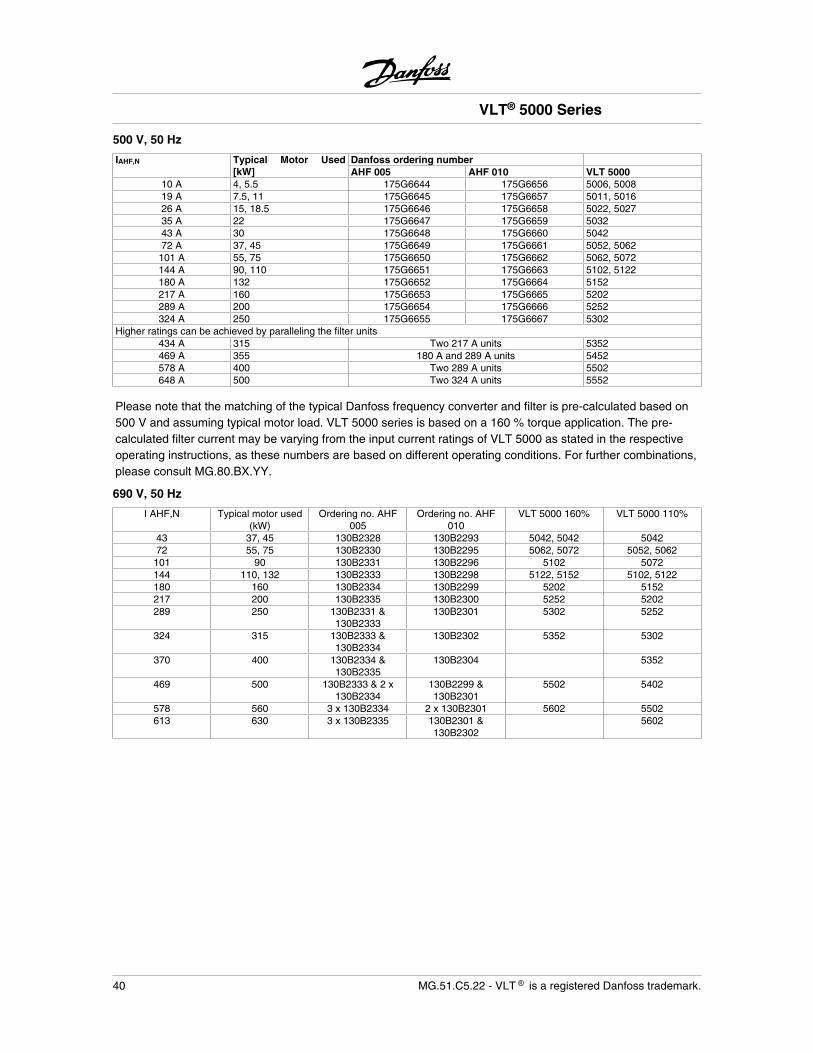
500 V, 50 Hz
IAHF,N Typical Motor Used[kW]
Danfoss ordering numberAHF 005 AHF 010 VLT 5000
10 A 4, 5.5 175G6644 175G6656 5006, 500819 A 7.5, 11 175G6645 175G6657 5011, 501626 A 15, 18.5 175G6646 175G6658 5022, 502735 A 22 175G6647 175G6659 503243 A 30 175G6648 175G6660 504272 A 37, 45 175G6649 175G6661 5052, 5062101 A 55, 75 175G6650 175G6662 5062, 5072144 A 90, 110 175G6651 175G6663 5102, 5122180 A 132 175G6652 175G6664 5152217 A 160 175G6653 175G6665 5202289 A 200 175G6654 175G6666 5252324 A 250 175G6655 175G6667 5302
Higher ratings can be achieved by paralleling the filter units434 A 315 Two 217 A units 5352469 A 355 180 A and 289 A units 5452578 A 400 Two 289 A units 5502648 A 500 Two 324 A units 5552
Please note that the matching of the typical Danfoss frequency converter and filter is pre-calculated based on500 V and assuming typical motor load. VLT 5000 series is based on a 160 % torque application. The pre-calculated filter current may be varying from the input current ratings of VLT 5000 as stated in the respectiveoperating instructions, as these numbers are based on different operating conditions. For further combinations,please consult MG.80.BX.YY.
690 V, 50 Hz
I AHF,N Typical motor used(kW)
Ordering no. AHF005
Ordering no. AHF010
VLT 5000 160% VLT 5000 110%
43 37, 45 130B2328 130B2293 5042, 5042 504272 55, 75 130B2330 130B2295 5062, 5072 5052, 5062101 90 130B2331 130B2296 5102 5072144 110, 132 130B2333 130B2298 5122, 5152 5102, 5122180 160 130B2334 130B2299 5202 5152217 200 130B2335 130B2300 5252 5202289 250 130B2331 &
130B2333130B2301 5302 5252
324 315 130B2333 &130B2334
130B2302 5352 5302
370 400 130B2334 &130B2335
130B2304 5352
469 500 130B2333 & 2 x130B2334
130B2299 &130B2301
5502 5402
578 560 3 x 130B2334 2 x 130B2301 5602 5502613 630 3 x 130B2335 130B2301 &
130B23025602
VLT® 5000 Series
40 MG.51.C5.22 - VLT is a registered Danfoss trademark.
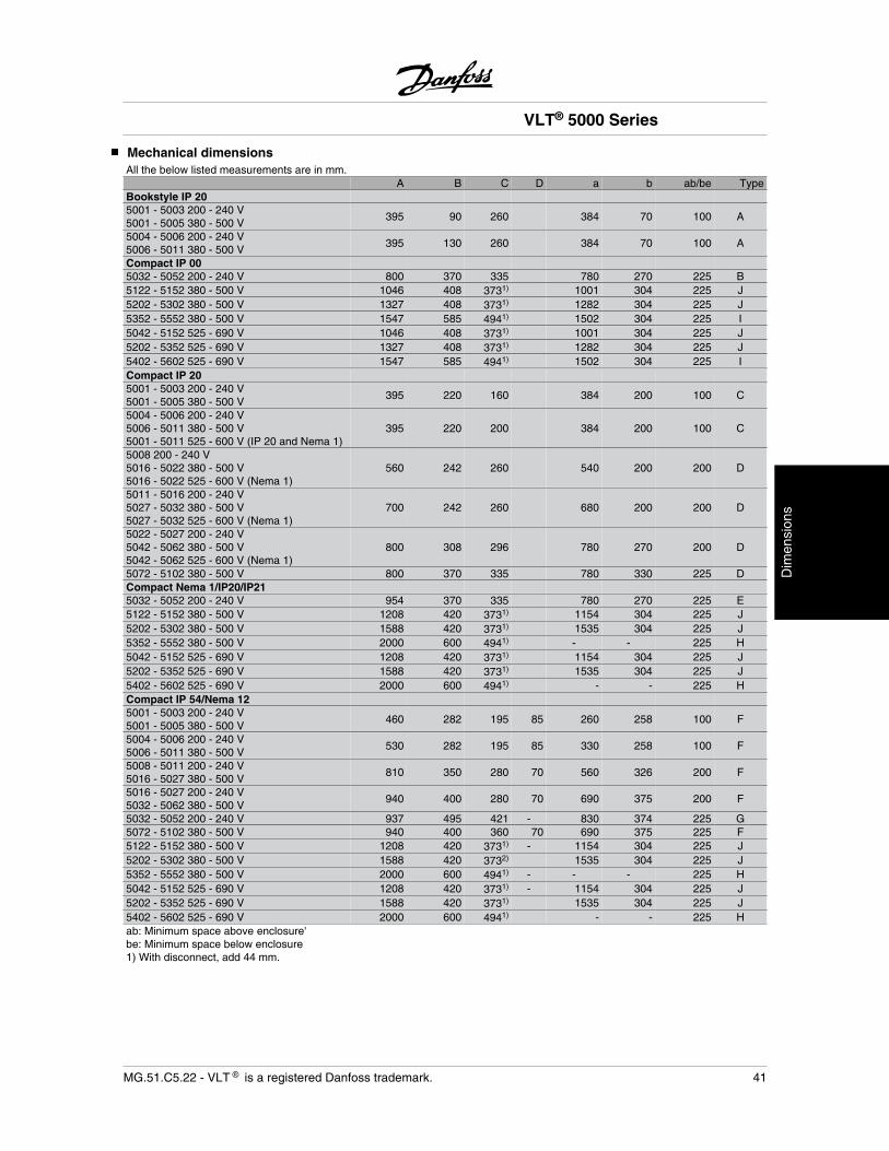
Mechanical dimensionsAll the below listed measurements are in mm.
A B C D a b ab/be TypeBookstyle IP 205001 - 5003 200 - 240 V5001 - 5005 380 - 500 V
395 90 260 384 70 100 A
5004 - 5006 200 - 240 V5006 - 5011 380 - 500 V
395 130 260 384 70 100 A
Compact IP 005032 - 5052 200 - 240 V 800 370 335 780 270 225 B5122 - 5152 380 - 500 V 1046 408 3731) 1001 304 225 J5202 - 5302 380 - 500 V 1327 408 3731) 1282 304 225 J5352 - 5552 380 - 500 V 1547 585 4941) 1502 304 225 I5042 - 5152 525 - 690 V 1046 408 3731) 1001 304 225 J5202 - 5352 525 - 690 V 1327 408 3731) 1282 304 225 J5402 - 5602 525 - 690 V 1547 585 4941) 1502 304 225 ICompact IP 205001 - 5003 200 - 240 V5001 - 5005 380 - 500 V
395 220 160 384 200 100 C
5004 - 5006 200 - 240 V5006 - 5011 380 - 500 V5001 - 5011 525 - 600 V (IP 20 and Nema 1)
395 220 200 384 200 100 C
5008 200 - 240 V5016 - 5022 380 - 500 V5016 - 5022 525 - 600 V (Nema 1)
560 242 260 540 200 200 D
5011 - 5016 200 - 240 V5027 - 5032 380 - 500 V5027 - 5032 525 - 600 V (Nema 1)
700 242 260 680 200 200 D
5022 - 5027 200 - 240 V5042 - 5062 380 - 500 V5042 - 5062 525 - 600 V (Nema 1)
800 308 296 780 270 200 D
5072 - 5102 380 - 500 V 800 370 335 780 330 225 DCompact Nema 1/IP20/IP215032 - 5052 200 - 240 V 954 370 335 780 270 225 E5122 - 5152 380 - 500 V 1208 420 3731) 1154 304 225 J5202 - 5302 380 - 500 V 1588 420 3731) 1535 304 225 J5352 - 5552 380 - 500 V 2000 600 4941) - - 225 H5042 - 5152 525 - 690 V 1208 420 3731) 1154 304 225 J5202 - 5352 525 - 690 V 1588 420 3731) 1535 304 225 J5402 - 5602 525 - 690 V 2000 600 4941) - - 225 HCompact IP 54/Nema 125001 - 5003 200 - 240 V5001 - 5005 380 - 500 V
460 282 195 85 260 258 100 F
5004 - 5006 200 - 240 V5006 - 5011 380 - 500 V
530 282 195 85 330 258 100 F
5008 - 5011 200 - 240 V5016 - 5027 380 - 500 V
810 350 280 70 560 326 200 F
5016 - 5027 200 - 240 V5032 - 5062 380 - 500 V
940 400 280 70 690 375 200 F
5032 - 5052 200 - 240 V 937 495 421 - 830 374 225 G5072 - 5102 380 - 500 V 940 400 360 70 690 375 225 F5122 - 5152 380 - 500 V 1208 420 3731) - 1154 304 225 J5202 - 5302 380 - 500 V 1588 420 3732) 1535 304 225 J5352 - 5552 380 - 500 V 2000 600 4941) - - - 225 H5042 - 5152 525 - 690 V 1208 420 3731) - 1154 304 225 J5202 - 5352 525 - 690 V 1588 420 3731) 1535 304 225 J5402 - 5602 525 - 690 V 2000 600 4941) - - 225 Hab: Minimum space above enclosure'be: Minimum space below enclosure1) With disconnect, add 44 mm.
VLT® 5000 Series
MG.51.C5.22 - VLT is a registered Danfoss trademark. 41
Dim
ensi
ons
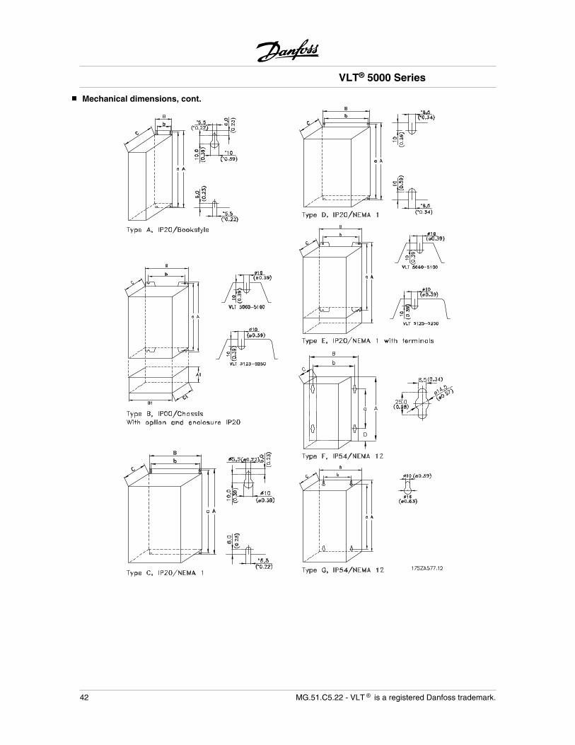
Mechanical dimensions, cont.
VLT® 5000 Series
42 MG.51.C5.22 - VLT is a registered Danfoss trademark.
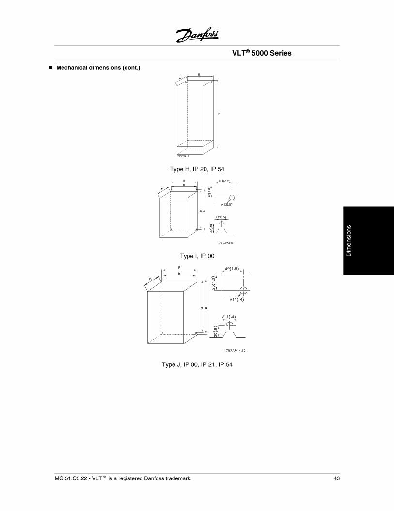
Mechanical dimensions (cont.)
Type H, IP 20, IP 54
Type I, IP 00
Type J, IP 00, IP 21, IP 54
VLT® 5000 Series
MG.51.C5.22 - VLT is a registered Danfoss trademark. 43
Dim
ensi
ons
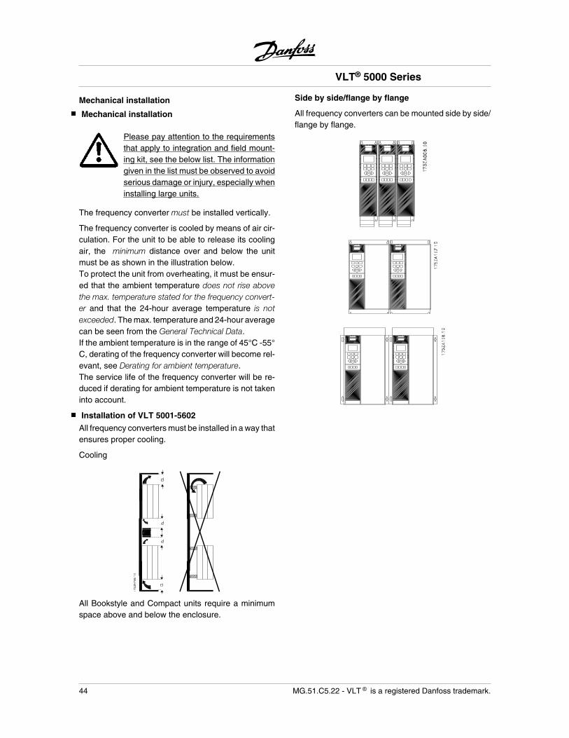
Mechanical installation
Mechanical installation
Please pay attention to the requirementsthat apply to integration and field mount-ing kit, see the below list. The informationgiven in the list must be observed to avoidserious damage or injury, especially wheninstalling large units.
The frequency converter must be installed vertically.
The frequency converter is cooled by means of air cir-culation. For the unit to be able to release its coolingair, the minimum distance over and below the unitmust be as shown in the illustration below.To protect the unit from overheating, it must be ensur-ed that the ambient temperature does not rise abovethe max. temperature stated for the frequency convert-er and that the 24-hour average temperature is notexceeded. The max. temperature and 24-hour averagecan be seen from the General Technical Data.If the ambient temperature is in the range of 45°C -55°C, derating of the frequency converter will become rel-evant, see Derating for ambient temperature.The service life of the frequency converter will be re-duced if derating for ambient temperature is not takeninto account.
Installation of VLT 5001-5602
All frequency converters must be installed in a way thatensures proper cooling.
Cooling
All Bookstyle and Compact units require a minimumspace above and below the enclosure.
Side by side/flange by flange
All frequency converters can be mounted side by side/flange by flange.
VLT® 5000 Series
44 MG.51.C5.22 - VLT is a registered Danfoss trademark.
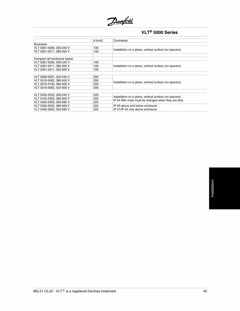
d [mm] CommentsBookstyleVLT 5001-5006, 200-240 V 100
Installation on a plane, vertical surface (no spacers)VLT 5001-5011, 380-500 V 100
Compact (all enclosure types)VLT 5001-5006, 200-240 V 100
Installation on a plane, vertical surface (no spacers)VLT 5001-5011, 380-500 V 100VLT 5001-5011, 525-600 V 100
VLT 5008-5027, 200-240 V 200
Installation on a plane, vertical surface (no spacers)VLT 5016-5062, 380-500 V 200VLT 5072-5102, 380-500 V 225VLT 5016-5062, 525-600 V 200
VLT 5032-5052, 200-240 V 225Installation on a plane, vertical surface (no spacers)IP 54 filter mats must be changed when they are dirty.
VLT 5122-5302, 380-500 V 225VLT 5042-5352, 525-690 V 225VLT 5352-5552, 380-500 V 225 IP 00 above and below enclosure
IP 21/IP 54 only above enclosureVLT 5402-5602, 525-690 V 225
VLT® 5000 Series
MG.51.C5.22 - VLT is a registered Danfoss trademark. 45
Inst
alla
tion
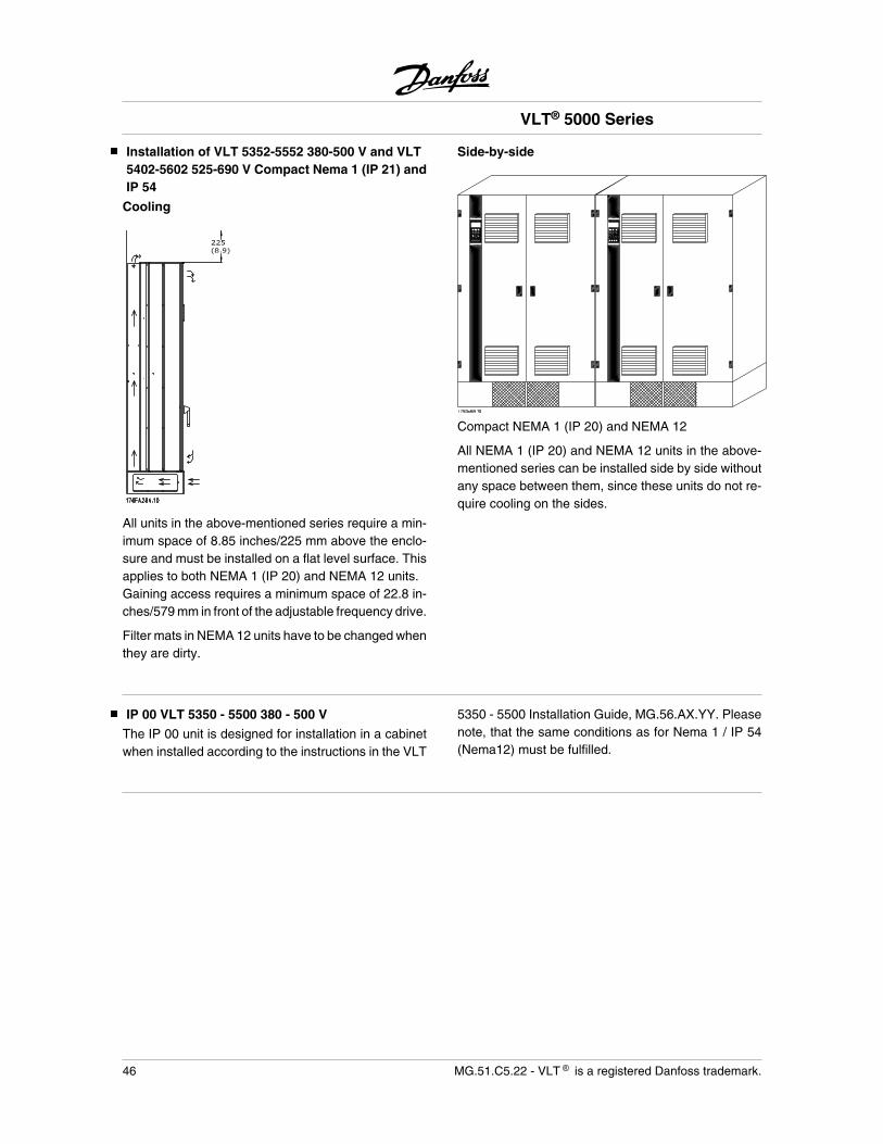
Installation of VLT 5352-5552 380-500 V and VLT5402-5602 525-690 V Compact Nema 1 (IP 21) andIP 54
Cooling
All units in the above-mentioned series require a min-imum space of 8.85 inches/225 mm above the enclo-sure and must be installed on a flat level surface. Thisapplies to both NEMA 1 (IP 20) and NEMA 12 units.Gaining access requires a minimum space of 22.8 in-ches/579 mm in front of the adjustable frequency drive.
Filter mats in NEMA 12 units have to be changed whenthey are dirty.
Side-by-side
Compact NEMA 1 (IP 20) and NEMA 12
All NEMA 1 (IP 20) and NEMA 12 units in the above-mentioned series can be installed side by side withoutany space between them, since these units do not re-quire cooling on the sides.
IP 00 VLT 5350 - 5500 380 - 500 V
The IP 00 unit is designed for installation in a cabinetwhen installed according to the instructions in the VLT
5350 - 5500 Installation Guide, MG.56.AX.YY. Pleasenote, that the same conditions as for Nema 1 / IP 54(Nema12) must be fulfilled.
VLT® 5000 Series
46 MG.51.C5.22 - VLT is a registered Danfoss trademark.
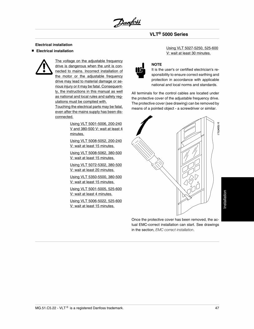
Electrical installation
Electrical installation
The voltage on the adjustable frequencydrive is dangerous when the unit is con-nected to mains. Incorrect installation ofthe motor or the adjustable frequencydrive may lead to material damage or se-rious injury or it may be fatal. Consequent-ly, the instructions in this manual as wellas national and local rules and safety reg-ulations must be complied with.Touching the electrical parts may be fatal,even after the mains supply has been dis-connected.
Using VLT 5001-5006, 200-240V and 380-500 V: wait at least 4minutes.
Using VLT 5008-5052, 200-240V: wait at least 15 minutes.
Using VLT 5008-5062, 380-500V: wait at least 15 minutes.
Using VLT 5072-5302, 380-500V: wait at least 20 minutes.
Using VLT 5350-5500, 380-500V: wait at least 15 minutes.
Using VLT 5001-5005, 525-600V: wait at least 4 minutes.
Using VLT 5006-5022, 525-600V: wait at least 15 minutes.
Using VLT 5027-5250, 525-600V: wait at least 30 minutes.
NOTEIt is the user's or certified electrician's re-sponsibility to ensure correct earthing andprotection in accordance with applicablenational and local norms and standards.
All terminals for the control cables are located underthe protective cover of the adjustable frequency drive.The protective cover (see drawing) can be removed bymeans of a pointed object - a screwdriver or similar.
Once the protective cover has been removed, the ac-tual EMC-correct installation can start. See drawingsin the section, EMC correct installation.
VLT® 5000 Series
MG.51.C5.22 - VLT is a registered Danfoss trademark. 47
Inst
alla
tion
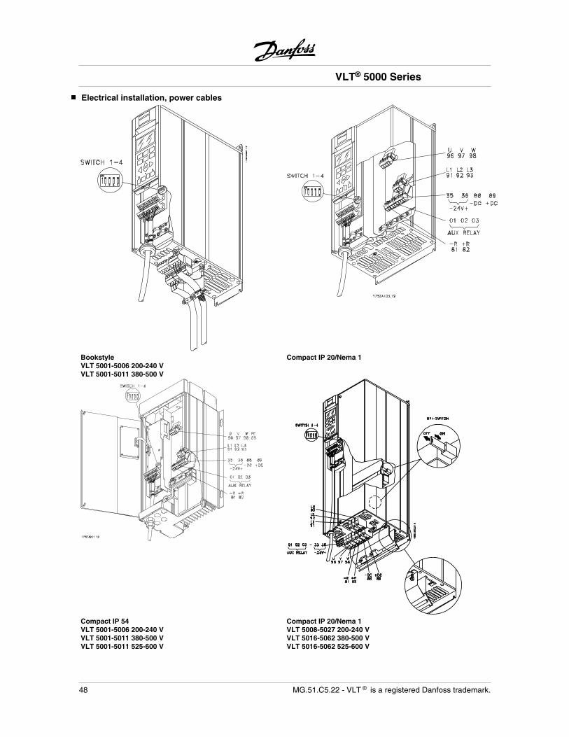
Electrical installation, power cables
BookstyleVLT 5001-5006 200-240 VVLT 5001-5011 380-500 V
Compact IP 20/Nema 1
Compact IP 54VLT 5001-5006 200-240 VVLT 5001-5011 380-500 VVLT 5001-5011 525-600 V
Compact IP 20/Nema 1VLT 5008-5027 200-240 VVLT 5016-5062 380-500 VVLT 5016-5062 525-600 V
VLT® 5000 Series
48 MG.51.C5.22 - VLT is a registered Danfoss trademark.
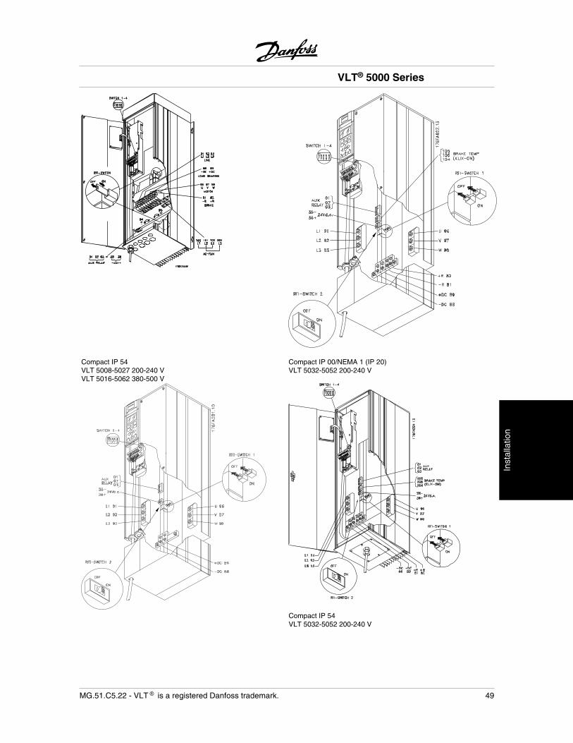
Compact IP 54VLT 5008-5027 200-240 VVLT 5016-5062 380-500 V
Compact IP 00/NEMA 1 (IP 20)VLT 5032-5052 200-240 V
Compact IP 54VLT 5032-5052 200-240 V
VLT® 5000 Series
MG.51.C5.22 - VLT is a registered Danfoss trademark. 49
Inst
alla
tion
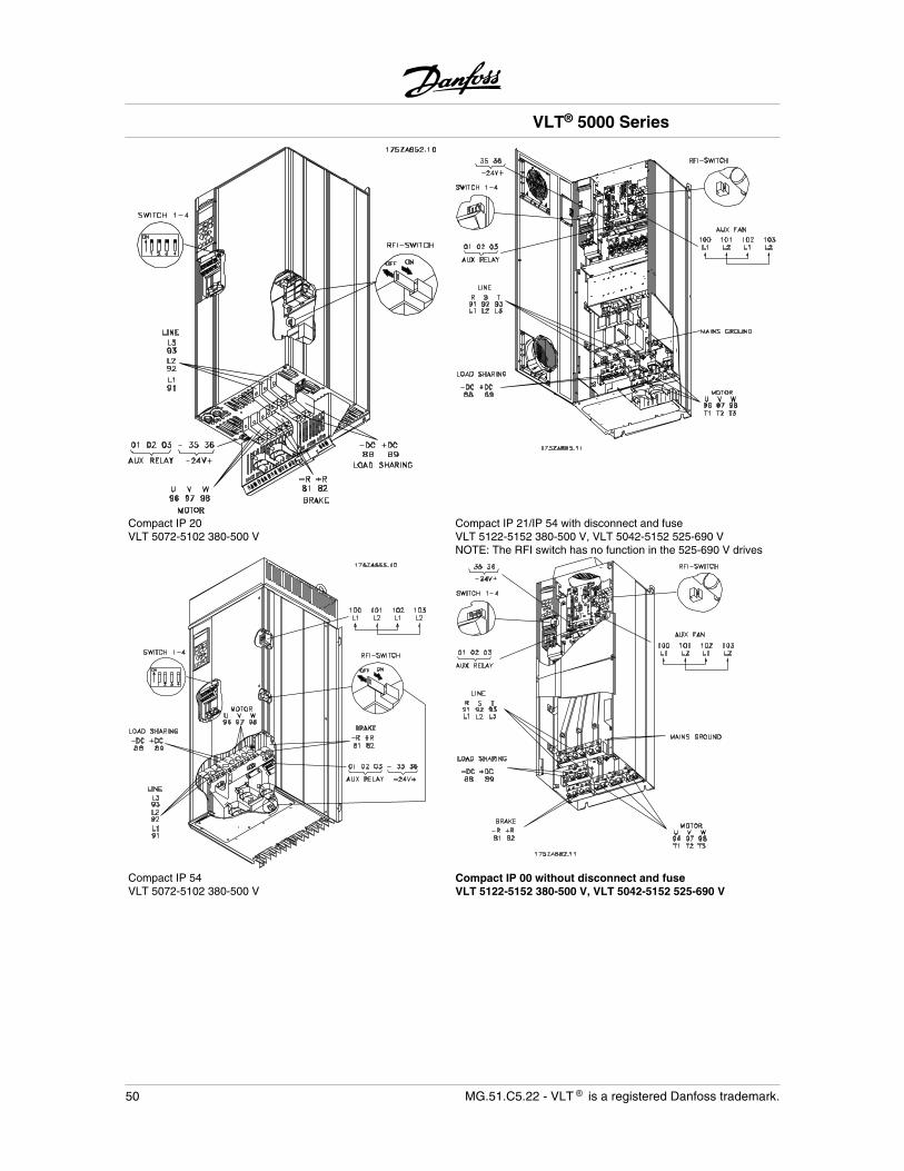
Compact IP 20VLT 5072-5102 380-500 V
Compact IP 21/IP 54 with disconnect and fuseVLT 5122-5152 380-500 V, VLT 5042-5152 525-690 VNOTE: The RFI switch has no function in the 525-690 V drives
Compact IP 54VLT 5072-5102 380-500 V
Compact IP 00 without disconnect and fuseVLT 5122-5152 380-500 V, VLT 5042-5152 525-690 V
VLT® 5000 Series
50 MG.51.C5.22 - VLT is a registered Danfoss trademark.
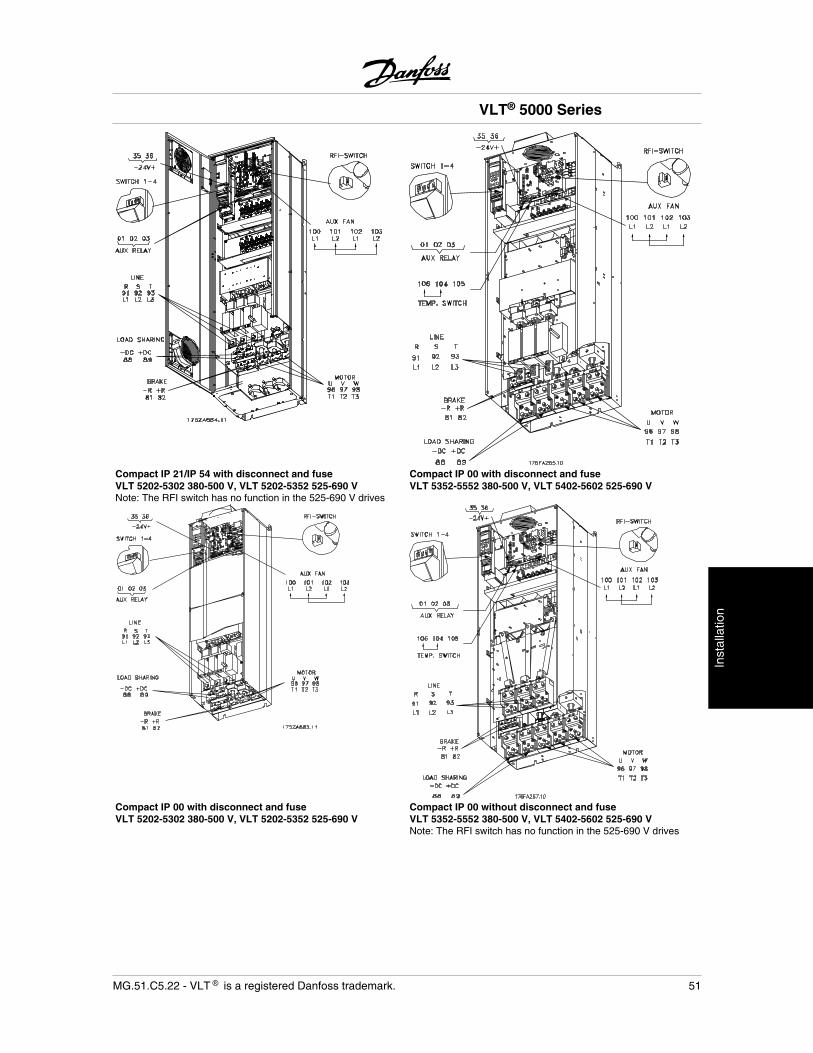
Compact IP 21/IP 54 with disconnect and fuseVLT 5202-5302 380-500 V, VLT 5202-5352 525-690 VNote: The RFI switch has no function in the 525-690 V drives
Compact IP 00 with disconnect and fuseVLT 5352-5552 380-500 V, VLT 5402-5602 525-690 V
Compact IP 00 with disconnect and fuseVLT 5202-5302 380-500 V, VLT 5202-5352 525-690 V
Compact IP 00 without disconnect and fuseVLT 5352-5552 380-500 V, VLT 5402-5602 525-690 VNote: The RFI switch has no function in the 525-690 V drives
VLT® 5000 Series
MG.51.C5.22 - VLT is a registered Danfoss trademark. 51
Inst
alla
tion
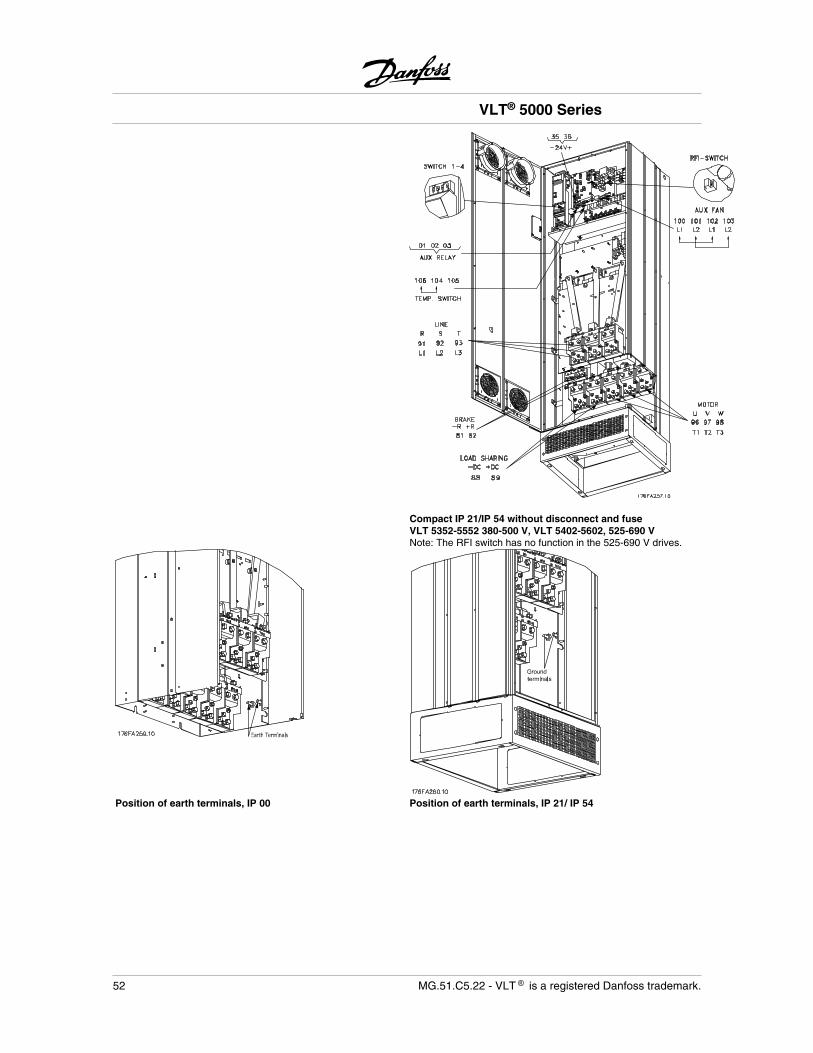
Compact IP 21/IP 54 without disconnect and fuseVLT 5352-5552 380-500 V, VLT 5402-5602, 525-690 VNote: The RFI switch has no function in the 525-690 V drives.
Position of earth terminals, IP 00 Position of earth terminals, IP 21/ IP 54
VLT® 5000 Series
52 MG.51.C5.22 - VLT is a registered Danfoss trademark.
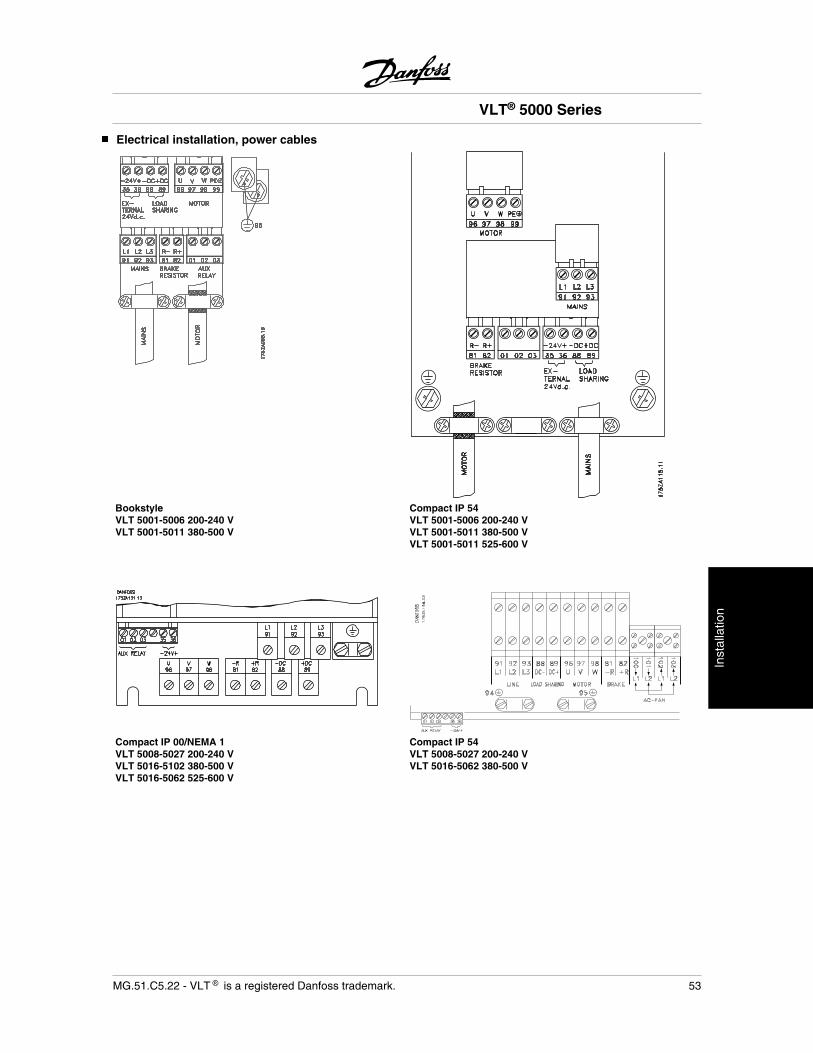
Electrical installation, power cables
BookstyleVLT 5001-5006 200-240 VVLT 5001-5011 380-500 V
Compact IP 54VLT 5001-5006 200-240 VVLT 5001-5011 380-500 VVLT 5001-5011 525-600 V
Compact IP 00/NEMA 1VLT 5008-5027 200-240 VVLT 5016-5102 380-500 VVLT 5016-5062 525-600 V
Compact IP 54VLT 5008-5027 200-240 VVLT 5016-5062 380-500 V
VLT® 5000 Series
MG.51.C5.22 - VLT is a registered Danfoss trademark. 53
Inst
alla
tion
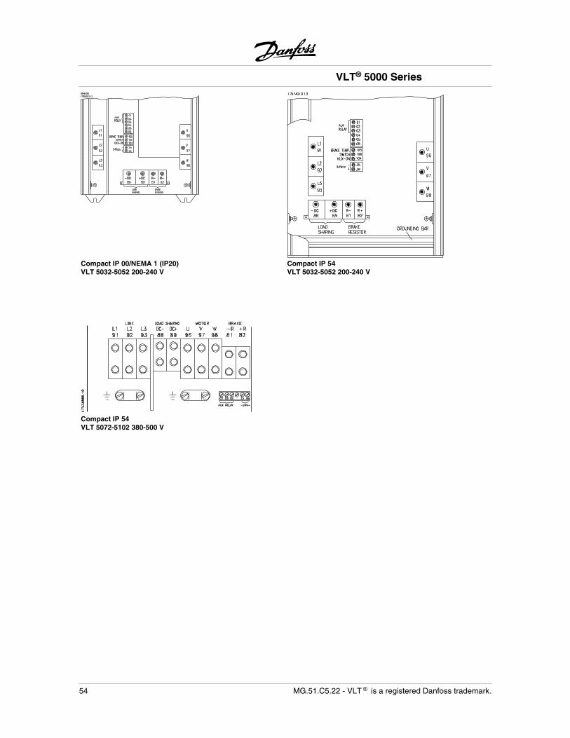
Compact IP 00/NEMA 1 (IP20)VLT 5032-5052 200-240 V
Compact IP 54VLT 5032-5052 200-240 V
Compact IP 54VLT 5072-5102 380-500 V
VLT® 5000 Series
54 MG.51.C5.22 - VLT is a registered Danfoss trademark.
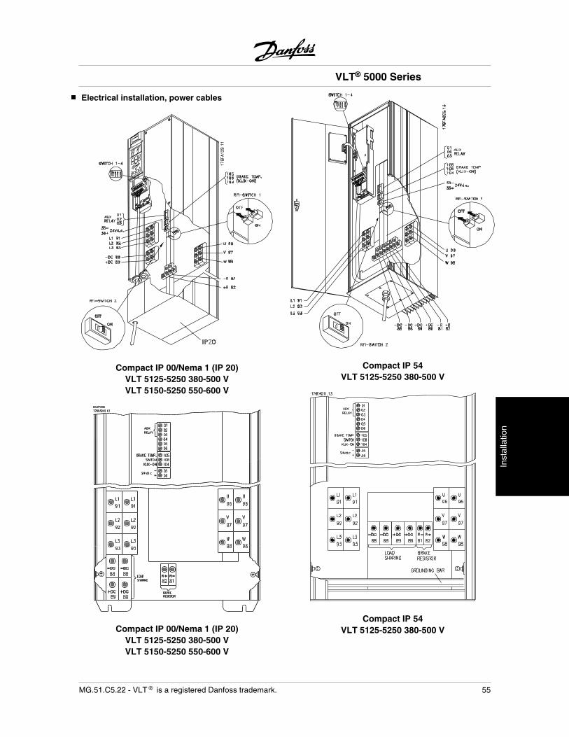
Electrical installation, power cables
Compact IP 00/Nema 1 (IP 20)VLT 5125-5250 380-500 VVLT 5150-5250 550-600 V
Compact IP 00/Nema 1 (IP 20)VLT 5125-5250 380-500 VVLT 5150-5250 550-600 V
Compact IP 54VLT 5125-5250 380-500 V
Compact IP 54VLT 5125-5250 380-500 V
VLT® 5000 Series
MG.51.C5.22 - VLT is a registered Danfoss trademark. 55
Inst
alla
tion
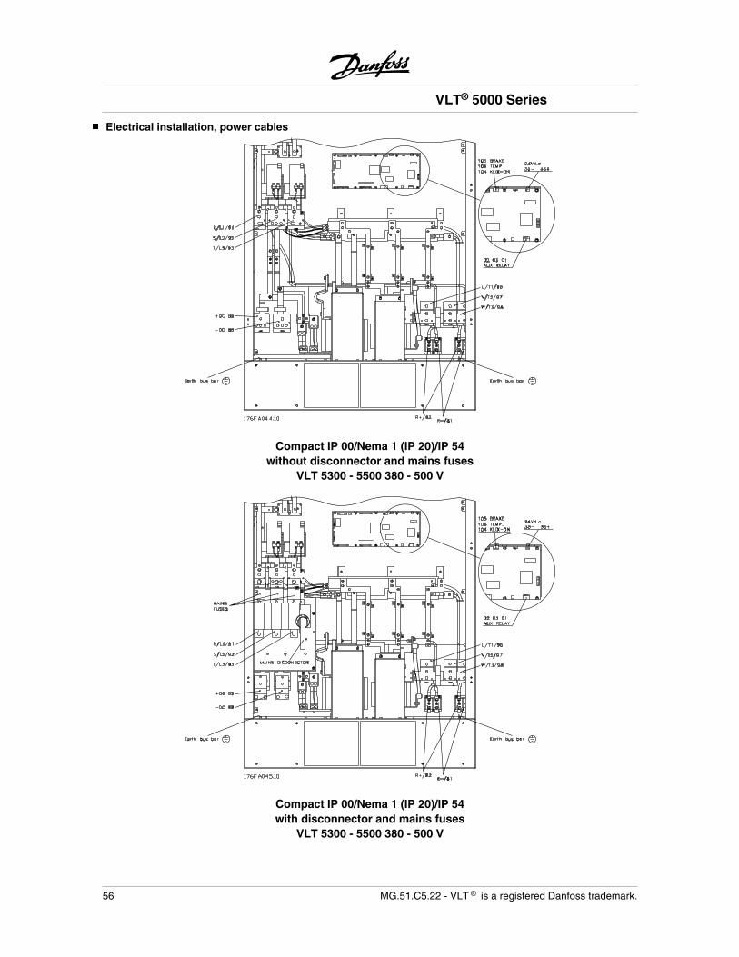
Electrical installation, power cables
Compact IP 00/Nema 1 (IP 20)/IP 54without disconnector and mains fuses
VLT 5300 - 5500 380 - 500 V
Compact IP 00/Nema 1 (IP 20)/IP 54with disconnector and mains fuses
VLT 5300 - 5500 380 - 500 V
VLT® 5000 Series
56 MG.51.C5.22 - VLT is a registered Danfoss trademark.
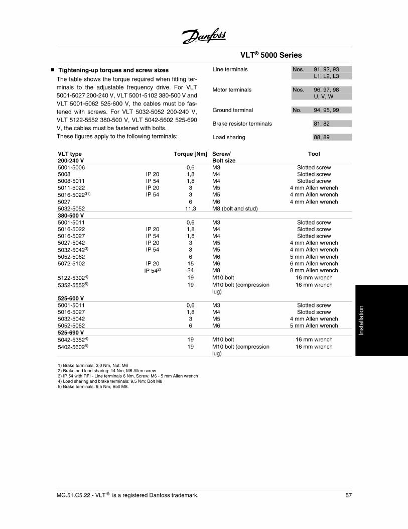
Tightening-up torques and screw sizes
The table shows the torque required when fitting ter-minals to the adjustable frequency drive. For VLT5001-5027 200-240 V, VLT 5001-5102 380-500 V andVLT 5001-5062 525-600 V, the cables must be fas-tened with screws. For VLT 5032-5052 200-240 V,VLT 5122-5552 380-500 V, VLT 5042-5602 525-690V, the cables must be fastened with bolts.These figures apply to the following terminals:
Line terminals Nos. 91, 92, 93L1, L2, L3
Motor terminals Nos. 96, 97, 98U, V, W
Ground terminal No. 94, 95, 99
Brake resistor terminals 81, 82
Load sharing 88, 89
VLT type200-240 V
Torque [Nm] Screw/Bolt size
Tool
5001-5006 0,6 M3 Slotted screw5008 IP 20 1,8 M4 Slotted screw5008-5011 IP 54 1,8 M4 Slotted screw5011-5022 IP 20 3 M5 4 mm Allen wrench5016-502231) IP 54 3 M5 4 mm Allen wrench5027 6 M6 4 mm Allen wrench5032-5052 11,3 M8 (bolt and stud)380-500 V5001-5011 0,6 M3 Slotted screw5016-5022 IP 20 1,8 M4 Slotted screw5016-5027 IP 54 1,8 M4 Slotted screw5027-5042 IP 20 3 M5 4 mm Allen wrench5032-50423) IP 54 3 M5 4 mm Allen wrench5052-5062 6 M6 5 mm Allen wrench5072-5102 IP 20 15 M6 6 mm Allen wrench
IP 542) 24 M8 8 mm Allen wrench5122-53024) 19 M10 bolt 16 mm wrench5352-55525) 19 M10 bolt (compression
lug)16 mm wrench
525-600 V5001-5011 0,6 M3 Slotted screw5016-5027 1,8 M4 Slotted screw5032-5042 3 M5 4 mm Allen wrench5052-5062 6 M6 5 mm Allen wrench525-690 V5042-53524) 19 M10 bolt 16 mm wrench5402-56025) 19 M10 bolt (compression
lug)16 mm wrench
1) Brake terminals: 3,0 Nm, Nut: M62) Brake and load sharing: 14 Nm, M6 Allen screw3) IP 54 with RFI - Line terminals 6 Nm, Screw: M6 - 5 mm Allen wrench4) Load sharing and brake terminals: 9,5 Nm; Bolt M85) Brake terminals: 9,5 Nm; Bolt M8.
VLT® 5000 Series
MG.51.C5.22 - VLT is a registered Danfoss trademark. 57
Inst
alla
tion
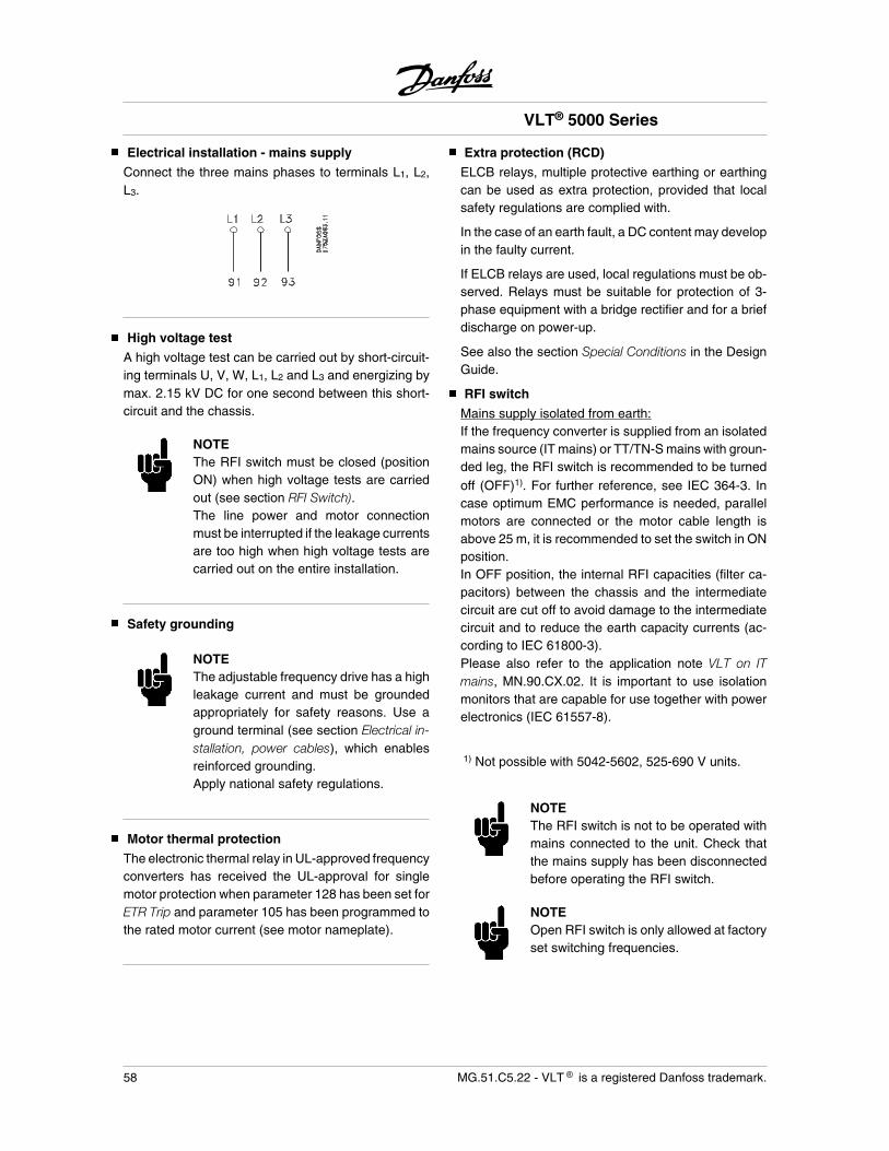
Electrical installation - mains supply
Connect the three mains phases to terminals L1, L2,L3.
High voltage test
A high voltage test can be carried out by short-circuit-ing terminals U, V, W, L1, L2 and L3 and energizing bymax. 2.15 kV DC for one second between this short-circuit and the chassis.
NOTEThe RFI switch must be closed (positionON) when high voltage tests are carriedout (see section RFI Switch).The line power and motor connectionmust be interrupted if the leakage currentsare too high when high voltage tests arecarried out on the entire installation.
Safety grounding
NOTEThe adjustable frequency drive has a highleakage current and must be groundedappropriately for safety reasons. Use aground terminal (see section Electrical in-stallation, power cables), which enablesreinforced grounding.Apply national safety regulations.
Motor thermal protection
The electronic thermal relay in UL-approved frequencyconverters has received the UL-approval for singlemotor protection when parameter 128 has been set forETR Trip and parameter 105 has been programmed tothe rated motor current (see motor nameplate).
Extra protection (RCD)
ELCB relays, multiple protective earthing or earthingcan be used as extra protection, provided that localsafety regulations are complied with.
In the case of an earth fault, a DC content may developin the faulty current.
If ELCB relays are used, local regulations must be ob-served. Relays must be suitable for protection of 3-phase equipment with a bridge rectifier and for a briefdischarge on power-up.
See also the section Special Conditions in the DesignGuide.
RFI switch
Mains supply isolated from earth:If the frequency converter is supplied from an isolatedmains source (IT mains) or TT/TN-S mains with groun-ded leg, the RFI switch is recommended to be turned
off (OFF)1). For further reference, see IEC 364-3. Incase optimum EMC performance is needed, parallelmotors are connected or the motor cable length isabove 25 m, it is recommended to set the switch in ONposition.In OFF position, the internal RFI capacities (filter ca-pacitors) between the chassis and the intermediatecircuit are cut off to avoid damage to the intermediatecircuit and to reduce the earth capacity currents (ac-cording to IEC 61800-3).Please also refer to the application note VLT on ITmains, MN.90.CX.02. It is important to use isolationmonitors that are capable for use together with powerelectronics (IEC 61557-8).
1) Not possible with 5042-5602, 525-690 V units.
NOTEThe RFI switch is not to be operated withmains connected to the unit. Check thatthe mains supply has been disconnectedbefore operating the RFI switch.
NOTEOpen RFI switch is only allowed at factoryset switching frequencies.
VLT® 5000 Series
58 MG.51.C5.22 - VLT is a registered Danfoss trademark.
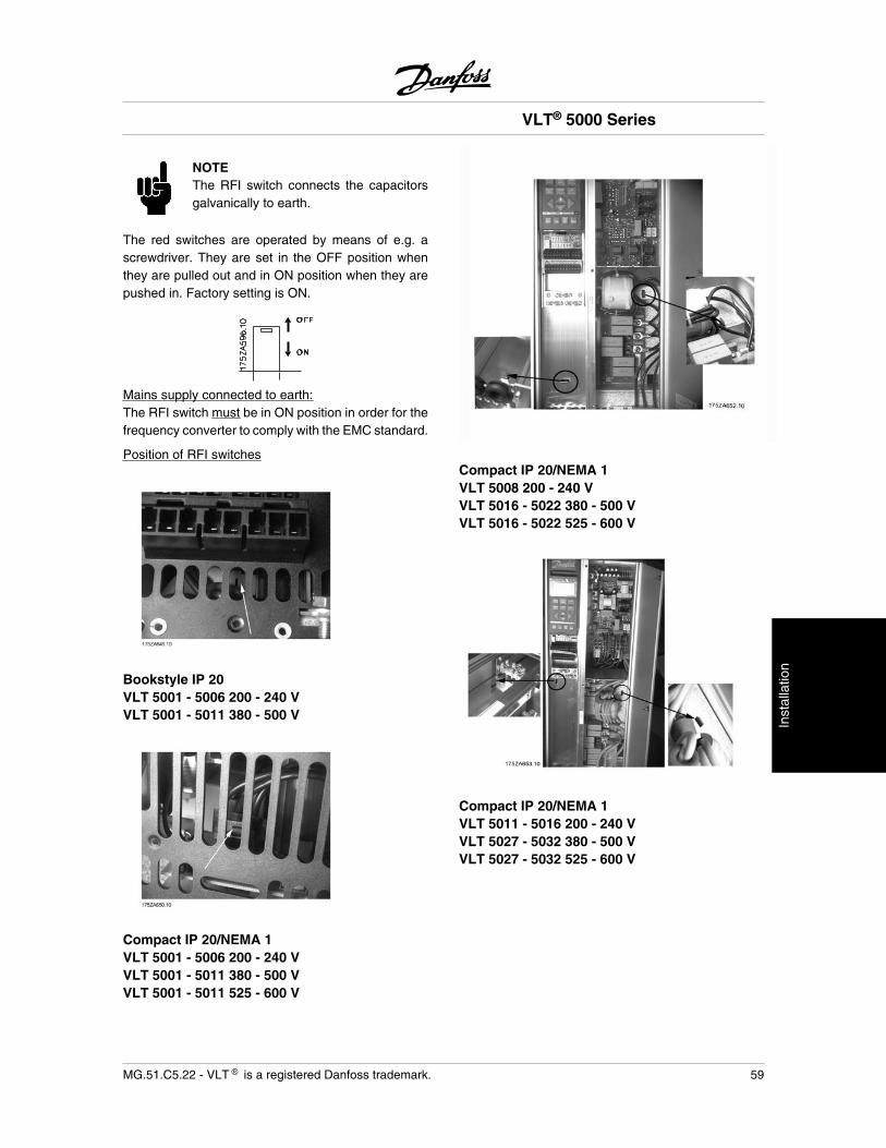
NOTEThe RFI switch connects the capacitorsgalvanically to earth.
The red switches are operated by means of e.g. ascrewdriver. They are set in the OFF position whenthey are pulled out and in ON position when they arepushed in. Factory setting is ON.
Mains supply connected to earth:The RFI switch must be in ON position in order for thefrequency converter to comply with the EMC standard.
Position of RFI switches
Bookstyle IP 20VLT 5001 - 5006 200 - 240 VVLT 5001 - 5011 380 - 500 V
Compact IP 20/NEMA 1VLT 5001 - 5006 200 - 240 VVLT 5001 - 5011 380 - 500 VVLT 5001 - 5011 525 - 600 V
Compact IP 20/NEMA 1VLT 5008 200 - 240 VVLT 5016 - 5022 380 - 500 VVLT 5016 - 5022 525 - 600 V
Compact IP 20/NEMA 1VLT 5011 - 5016 200 - 240 VVLT 5027 - 5032 380 - 500 VVLT 5027 - 5032 525 - 600 V
VLT® 5000 Series
MG.51.C5.22 - VLT is a registered Danfoss trademark. 59
Inst
alla
tion
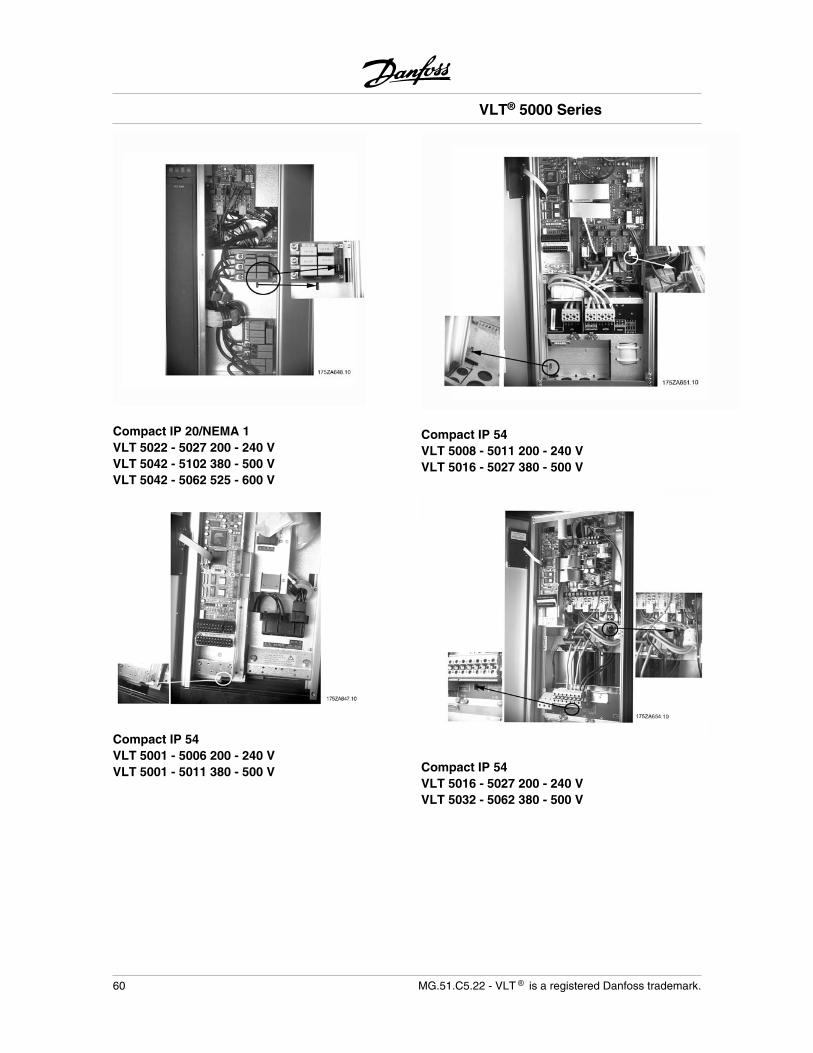
Compact IP 20/NEMA 1VLT 5022 - 5027 200 - 240 VVLT 5042 - 5102 380 - 500 VVLT 5042 - 5062 525 - 600 V
Compact IP 54VLT 5001 - 5006 200 - 240 VVLT 5001 - 5011 380 - 500 V
Compact IP 54VLT 5008 - 5011 200 - 240 VVLT 5016 - 5027 380 - 500 V
Compact IP 54VLT 5016 - 5027 200 - 240 VVLT 5032 - 5062 380 - 500 V
VLT® 5000 Series
60 MG.51.C5.22 - VLT is a registered Danfoss trademark.
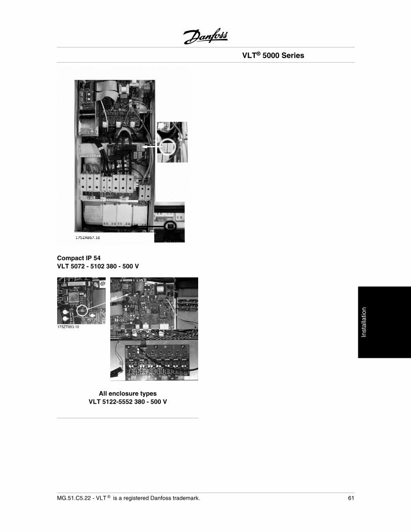
Compact IP 54VLT 5072 - 5102 380 - 500 V
All enclosure typesVLT 5122-5552 380 - 500 V
VLT® 5000 Series
MG.51.C5.22 - VLT is a registered Danfoss trademark. 61
Inst
alla
tion
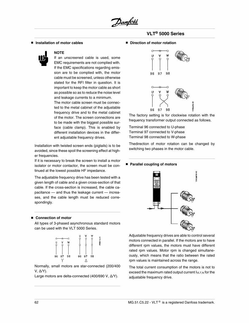
Installation of motor cables
NOTEIf an unscreened cable is used, someEMC requirements are not complied with.If the EMC specifications regarding emis-sion are to be complied with, the motorcable must be screened, unless otherwisestated for the RFI filter in question. It isimportant to keep the motor cable as shortas possible so as to reduce the noise leveland leakage currents to a minimum.The motor cable screen must be connec-ted to the metal cabinet of the adjustablefrequency drive and to the metal cabinetof the motor. The screen connections areto be made with the biggest possible sur-face (cable clamp). This is enabled bydifferent installation devices in the differ-ent adjustable frequency drives.
Installation with twisted screen ends (pigtails) is to beavoided, since these spoil the screening effect at high-er frequencies.If it is necessary to break the screen to install a motorisolator or motor contactor, the screen must be con-tinued at the lowest possible HF impedance.
The adjustable frequency drive has been tested with agiven length of cable and a given cross-section of thatcable. If the cross-section is increased, the cable ca-pacitance — and thus the leakage current — increa-ses, and the cable length must be reduced corre-spondingly.
Connection of motor
All types of 3-phased asynchronous standard motorscan be used with the VLT 5000 Series.
Normally, small motors are star-connected (200/400V, /Y).Large motors are delta-connected (400/690 V, /Y).
Direction of motor rotation
The factory setting is for clockwise rotation with thefrequency transformer output connected as follows.
Terminal 96 connected to U-phaseTerminal 97 connected to V-phaseTerminal 98 connected to W-phase
Thedirection of motor rotation can be changed byswitching two phases in the motor cable.
Parallel coupling of motors
Adjustable frequency drives are able to control severalmotors connected in parallel. If the motors are to havedifferent rpm values, the motors must have differentrated rpm values. Motor rpm is changed simultane-ously, which means that the ratio between the ratedrpm values is maintained across the range.
The total current consumption of the motors is not toexceed the maximum rated output current IVLT,N for theadjustable frequency drive.
VLT® 5000 Series
62 MG.51.C5.22 - VLT is a registered Danfoss trademark.
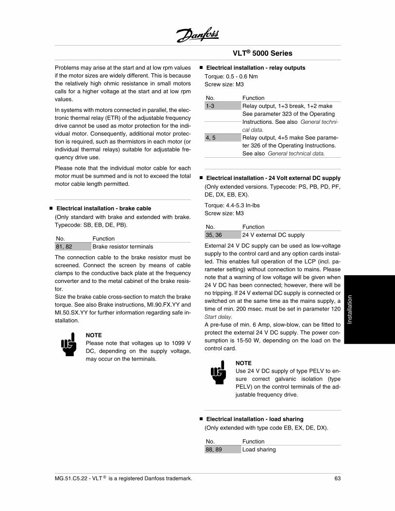
Problems may arise at the start and at low rpm valuesif the motor sizes are widely different. This is becausethe relatively high ohmic resistance in small motorscalls for a higher voltage at the start and at low rpmvalues.
In systems with motors connected in parallel, the elec-tronic thermal relay (ETR) of the adjustable frequencydrive cannot be used as motor protection for the indi-vidual motor. Consequently, additional motor protec-tion is required, such as thermistors in each motor (orindividual thermal relays) suitable for adjustable fre-quency drive use.
Please note that the individual motor cable for eachmotor must be summed and is not to exceed the totalmotor cable length permitted.
Electrical installation - brake cable
(Only standard with brake and extended with brake.Typecode: SB, EB, DE, PB).
No. Function81, 82 Brake resistor terminals
The connection cable to the brake resistor must bescreened. Connect the screen by means of cableclamps to the conductive back plate at the frequencyconverter and to the metal cabinet of the brake resis-tor.Size the brake cable cross-section to match the braketorque. See also Brake instructions, MI.90.FX.YY andMI.50.SX.YY for further information regarding safe in-stallation.
NOTEPlease note that voltages up to 1099 VDC, depending on the supply voltage,may occur on the terminals.
Electrical installation - relay outputs
Torque: 0.5 - 0.6 NmScrew size: M3
No. Function1-3 Relay output, 1+3 break, 1+2 make
See parameter 323 of the OperatingInstructions. See also General techni-cal data.
4, 5 Relay output, 4+5 make See parame-ter 326 of the Operating Instructions.See also General technical data.
Electrical installation - 24 Volt external DC supply
(Only extended versions. Typecode: PS, PB, PD, PF,DE, DX, EB, EX).
Torque: 4.4-5.3 In-lbsScrew size: M3
No. Function35, 36 24 V external DC supply
External 24 V DC supply can be used as low-voltagesupply to the control card and any option cards instal-led. This enables full operation of the LCP (incl. pa-rameter setting) without connection to mains. Pleasenote that a warning of low voltage will be given when24 V DC has been connected; however, there will beno tripping. If 24 V external DC supply is connected orswitched on at the same time as the mains supply, atime of min. 200 msec. must be set in parameter 120Start delay.A pre-fuse of min. 6 Amp, slow-blow, can be fitted toprotect the external 24 V DC supply. The power con-sumption is 15-50 W, depending on the load on thecontrol card.
NOTEUse 24 V DC supply of type PELV to en-sure correct galvanic isolation (typePELV) on the control terminals of the ad-justable frequency drive.
Electrical installation - load sharing
(Only extended with type code EB, EX, DE, DX).
No. Function88, 89 Load sharing
VLT® 5000 Series
MG.51.C5.22 - VLT is a registered Danfoss trademark. 63
Inst
alla
tion
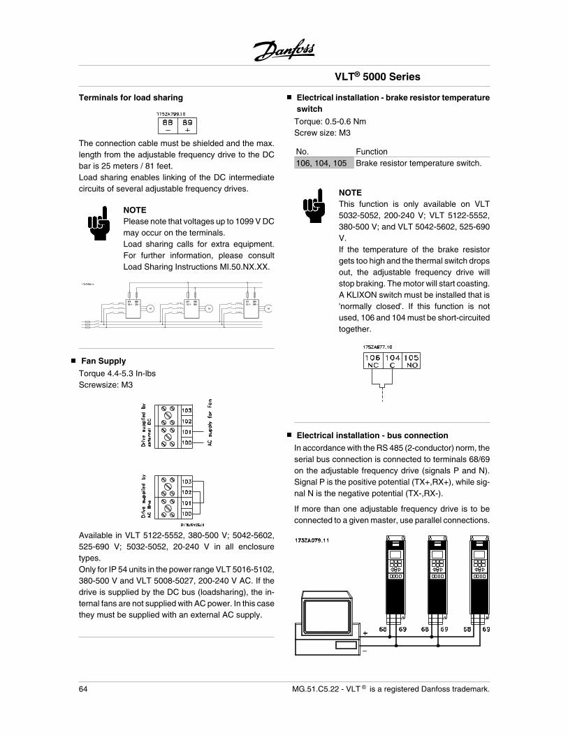
Terminals for load sharing
The connection cable must be shielded and the max.length from the adjustable frequency drive to the DCbar is 25 meters / 81 feet.Load sharing enables linking of the DC intermediatecircuits of several adjustable frequency drives.
NOTEPlease note that voltages up to 1099 V DCmay occur on the terminals.Load sharing calls for extra equipment.For further information, please consultLoad Sharing Instructions MI.50.NX.XX.
Fan Supply
Torque 4.4-5.3 In-lbsScrewsize: M3
Available in VLT 5122-5552, 380-500 V; 5042-5602,525-690 V; 5032-5052, 20-240 V in all enclosuretypes.Only for IP 54 units in the power range VLT 5016-5102,380-500 V and VLT 5008-5027, 200-240 V AC. If thedrive is supplied by the DC bus (loadsharing), the in-ternal fans are not supplied with AC power. In this casethey must be supplied with an external AC supply.
Electrical installation - brake resistor temperatureswitch
Torque: 0.5-0.6 NmScrew size: M3
No. Function106, 104, 105 Brake resistor temperature switch.
NOTEThis function is only available on VLT5032-5052, 200-240 V; VLT 5122-5552,380-500 V; and VLT 5042-5602, 525-690V.If the temperature of the brake resistorgets too high and the thermal switch dropsout, the adjustable frequency drive willstop braking. The motor will start coasting.A KLIXON switch must be installed that is'normally closed'. If this function is notused, 106 and 104 must be short-circuitedtogether.
Electrical installation - bus connection
In accordance with the RS 485 (2-conductor) norm, theserial bus connection is connected to terminals 68/69on the adjustable frequency drive (signals P and N).Signal P is the positive potential (TX+,RX+), while sig-nal N is the negative potential (TX-,RX-).
If more than one adjustable frequency drive is to beconnected to a given master, use parallel connections.
VLT® 5000 Series
64 MG.51.C5.22 - VLT is a registered Danfoss trademark.
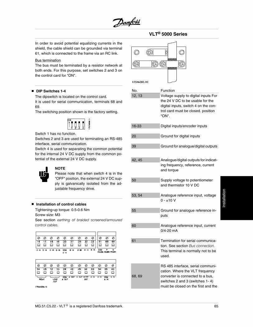
In order to avoid potential equalizing currents in theshield, the cable shield can be grounded via terminal61, which is connected to the frame via an RC link.
Bus terminationThe bus must be terminated by a resistor network atboth ends. For this purpose, set switches 2 and 3 onthe control card for "ON".
DIP Switches 1-4
The dipswitch is located on the control card.It is used for serial communication, terminals 68 and69.The switching position shown is the factory setting.
Switch 1 has no function.Switches 2 and 3 are used for terminating an RS-485interface, serial communication.Switch 4 is used for separating the common potentialfor the internal 24 V DC supply from the common po-tential of the external 24 V DC supply.
NOTEPlease note that when switch 4 is in the"OFF" position, the external 24 V DC sup-ply is galvanically isolated from the ad-justable frequency drive.
Installation of control cables
Tightening-up torque: 0.5-0.6 NmScrew size: M3See section earthing of braided screened/armouredcontrol cables.
No. Function12, 13 Voltage supply to digital inputs For
the 24 V DC to be usable for thedigital inputs, switch 4 on the con-trol card must be closed. position"ON".
16-33 Digital inputs/encoder inputs
20 Ground for digital inputs
39 Ground for analogue/digital outputs
42, 45 Analogue/digital outputs for indicat-ing frequency, reference, currentand torque
50 Supply voltage to potentiometerand thermistor 10 V DC
53, 54 Analogue reference input, voltage0 - ±10 V
55 Ground for analogue reference in-puts
60 Analogue reference input, current0/4-20 mA
61 Termination for serial communica-tion. See section Bus connection.This terminal is normally not to beused.
68, 69
RS 485 interface, serial communi-cation. Where the VLT frequencyconverter is connected to a bus,switches 2 and 3 (switches 1- 4)must be closed on the first and the
VLT® 5000 Series
MG.51.C5.22 - VLT is a registered Danfoss trademark. 65
Inst
alla
tion
last VLT frequency converter. Onthe remaining VLT frequency con-verters, switches 2 and 3 must beopen. The factory setting is closed(position “ON”).
VLT® 5000 Series
66 MG.51.C5.22 - VLT is a registered Danfoss trademark.

Electrical installation
Conversion of analogue inputs
Current input signal to voltage input0-20 mA 0-10 V Connect 510 ohms resistor between input terminal 53
and 55 and adjust minimum and maximum values in pa-rameters 309, and 310 or 54 and 55 and adjust minimumand maximum values in parameters 312 and 313.
4-20 mA 2-10 V
VLT® 5000 Series
MG.51.C5.22 - VLT is a registered Danfoss trademark. 67
Inst
alla
tion
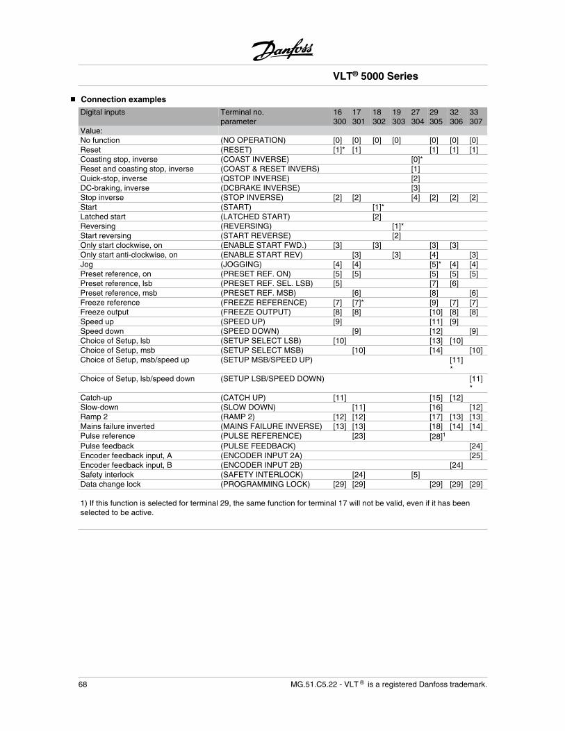
Connection examples
Digital inputs Terminal no. 16 17 18 19 27 29 32 33parameter 300 301 302 303 304 305 306 307
Value:No function (NO OPERATION) [0] [0] [0] [0] [0] [0] [0]Reset (RESET) [1]* [1] [1] [1] [1]Coasting stop, inverse (COAST INVERSE) [0]*Reset and coasting stop, inverse (COAST & RESET INVERS) [1]Quick-stop, inverse (QSTOP INVERSE) [2]DC-braking, inverse (DCBRAKE INVERSE) [3]Stop inverse (STOP INVERSE) [2] [2] [4] [2] [2] [2]Start (START) [1]*Latched start (LATCHED START) [2]Reversing (REVERSING) [1]*Start reversing (START REVERSE) [2]Only start clockwise, on (ENABLE START FWD.) [3] [3] [3] [3]Only start anti-clockwise, on (ENABLE START REV) [3] [3] [4] [3]Jog (JOGGING) [4] [4] [5]* [4] [4]Preset reference, on (PRESET REF. ON) [5] [5] [5] [5] [5]Preset reference, lsb (PRESET REF. SEL. LSB) [5] [7] [6]Preset reference, msb (PRESET REF. MSB) [6] [8] [6]Freeze reference (FREEZE REFERENCE) [7] [7]* [9] [7] [7]Freeze output (FREEZE OUTPUT) [8] [8] [10] [8] [8]Speed up (SPEED UP) [9] [11] [9]Speed down (SPEED DOWN) [9] [12] [9]Choice of Setup, lsb (SETUP SELECT LSB) [10] [13] [10]Choice of Setup, msb (SETUP SELECT MSB) [10] [14] [10]Choice of Setup, msb/speed up (SETUP MSB/SPEED UP) [11]
*Choice of Setup, lsb/speed down (SETUP LSB/SPEED DOWN) [11]
*Catch-up (CATCH UP) [11] [15] [12]Slow-down (SLOW DOWN) [11] [16] [12]Ramp 2 (RAMP 2) [12] [12] [17] [13] [13]Mains failure inverted (MAINS FAILURE INVERSE) [13] [13] [18] [14] [14]Pulse reference (PULSE REFERENCE) [23] [28]1
Pulse feedback (PULSE FEEDBACK) [24]Encoder feedback input, A (ENCODER INPUT 2A) [25]Encoder feedback input, B (ENCODER INPUT 2B) [24]Safety interlock (SAFETY INTERLOCK) [24] [5]Data change lock (PROGRAMMING LOCK) [29] [29] [29] [29] [29] 1) If this function is selected for terminal 29, the same function for terminal 17 will not be valid, even if it has beenselected to be active.
VLT® 5000 Series
68 MG.51.C5.22 - VLT is a registered Danfoss trademark.
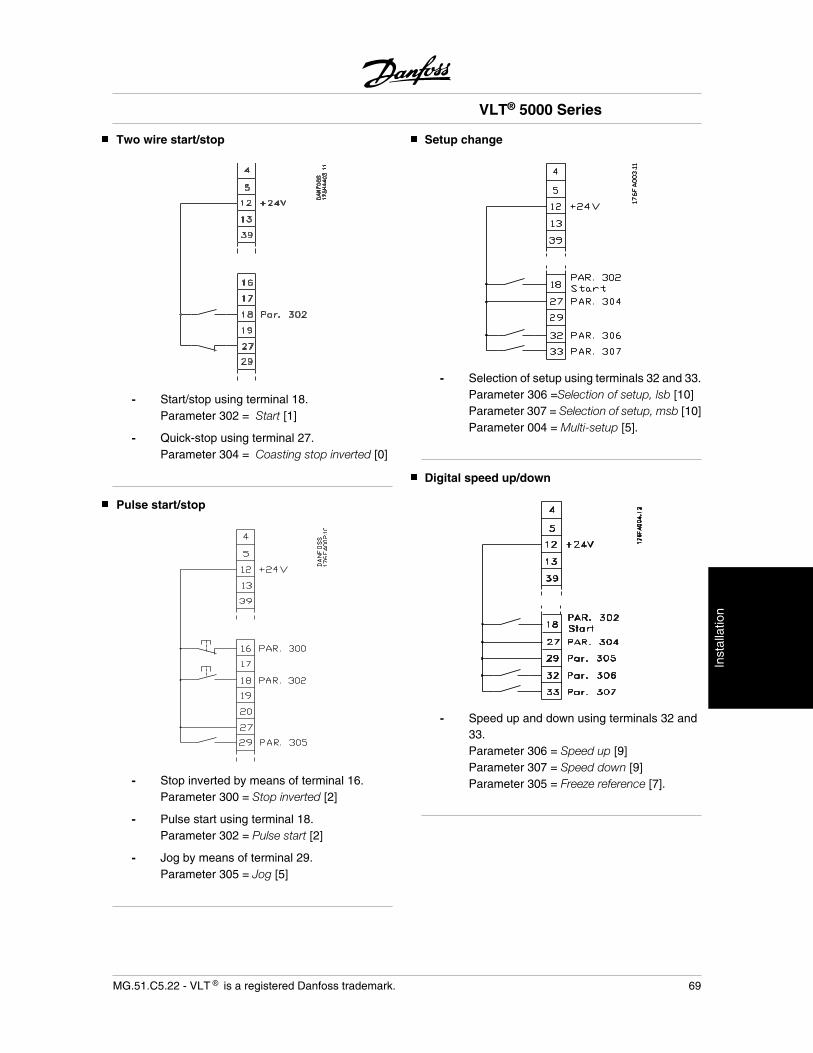
Two wire start/stop
- Start/stop using terminal 18.Parameter 302 = Start [1]
- Quick-stop using terminal 27.Parameter 304 = Coasting stop inverted [0]
Pulse start/stop
- Stop inverted by means of terminal 16.Parameter 300 = Stop inverted [2]
- Pulse start using terminal 18.Parameter 302 = Pulse start [2]
- Jog by means of terminal 29.Parameter 305 = Jog [5]
Setup change
- Selection of setup using terminals 32 and 33.Parameter 306 =Selection of setup, lsb [10]Parameter 307 = Selection of setup, msb [10]Parameter 004 = Multi-setup [5].
Digital speed up/down
- Speed up and down using terminals 32 and33.Parameter 306 = Speed up [9]Parameter 307 = Speed down [9]Parameter 305 = Freeze reference [7].
VLT® 5000 Series
MG.51.C5.22 - VLT is a registered Danfoss trademark. 69
Inst
alla
tion
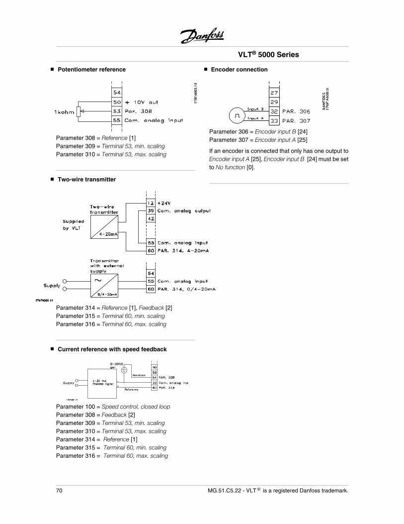
Potentiometer reference
Parameter 308 = Reference [1]Parameter 309 = Terminal 53, min. scalingParameter 310 = Terminal 53, max. scaling
Two-wire transmitter
Parameter 314 = Reference [1], Feedback [2]Parameter 315 = Terminal 60, min. scalingParameter 316 = Terminal 60, max. scaling
Current reference with speed feedback
Parameter 100 = Speed control, closed loopParameter 308 = Feedback [2]Parameter 309 = Terminal 53, min. scalingParameter 310 = Terminal 53, max. scalingParameter 314 = Reference [1]Parameter 315 = Terminal 60, min. scalingParameter 316 = Terminal 60, max. scaling
Encoder connection
Parameter 306 = Encoder input B [24]Parameter 307 = Encoder input A [25]
If an encoder is connected that only has one output toEncoder input A [25], Encoder input B [24] must be setto No function [0].
VLT® 5000 Series
70 MG.51.C5.22 - VLT is a registered Danfoss trademark.
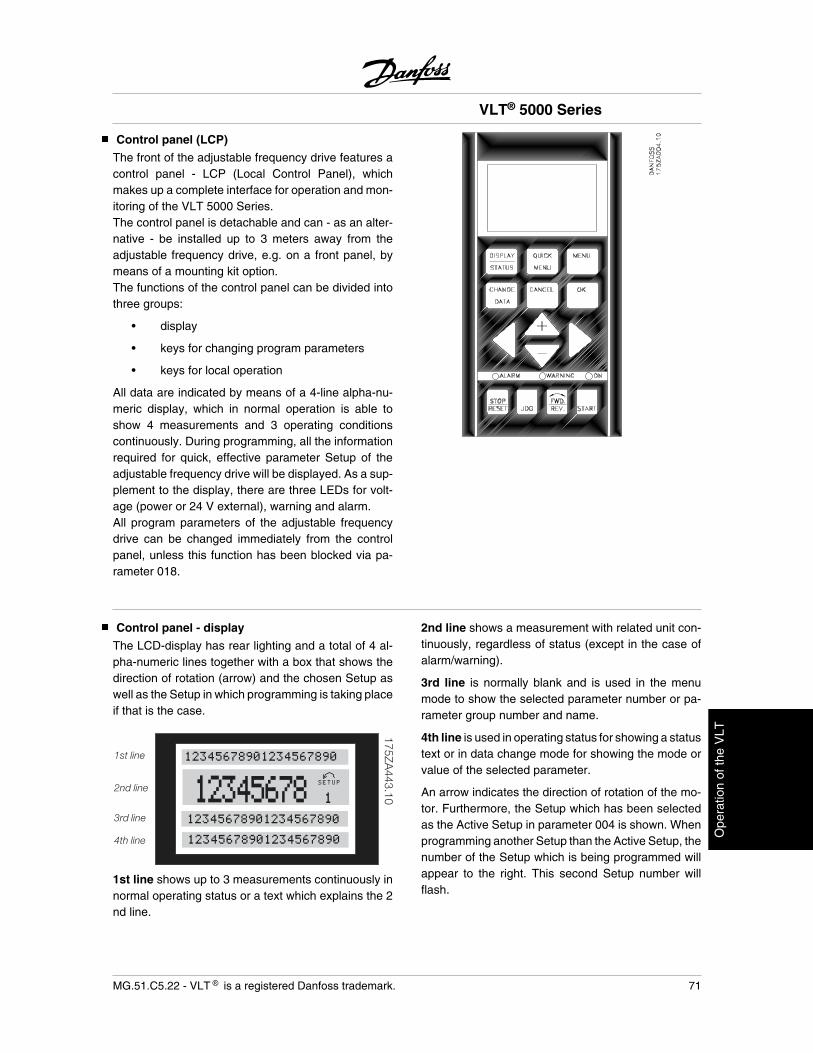
Control panel (LCP)
The front of the adjustable frequency drive features acontrol panel - LCP (Local Control Panel), whichmakes up a complete interface for operation and mon-itoring of the VLT 5000 Series.The control panel is detachable and can - as an alter-native - be installed up to 3 meters away from theadjustable frequency drive, e.g. on a front panel, bymeans of a mounting kit option.The functions of the control panel can be divided intothree groups:
• display
• keys for changing program parameters
• keys for local operation
All data are indicated by means of a 4-line alpha-nu-meric display, which in normal operation is able toshow 4 measurements and 3 operating conditionscontinuously. During programming, all the informationrequired for quick, effective parameter Setup of theadjustable frequency drive will be displayed. As a sup-plement to the display, there are three LEDs for volt-age (power or 24 V external), warning and alarm.All program parameters of the adjustable frequencydrive can be changed immediately from the controlpanel, unless this function has been blocked via pa-rameter 018.
Control panel - display
The LCD-display has rear lighting and a total of 4 al-pha-numeric lines together with a box that shows thedirection of rotation (arrow) and the chosen Setup aswell as the Setup in which programming is taking placeif that is the case.
12345678 SETUP
1
12345678901234567890
12345678901234567890
12345678901234567890
175ZA443.10
1st line
2nd line
3rd line
4th line
1st line shows up to 3 measurements continuously innormal operating status or a text which explains the 2nd line.
2nd line shows a measurement with related unit con-tinuously, regardless of status (except in the case ofalarm/warning).
3rd line is normally blank and is used in the menumode to show the selected parameter number or pa-rameter group number and name.
4th line is used in operating status for showing a statustext or in data change mode for showing the mode orvalue of the selected parameter.
An arrow indicates the direction of rotation of the mo-tor. Furthermore, the Setup which has been selectedas the Active Setup in parameter 004 is shown. Whenprogramming another Setup than the Active Setup, thenumber of the Setup which is being programmed willappear to the right. This second Setup number willflash.
VLT® 5000 Series
MG.51.C5.22 - VLT is a registered Danfoss trademark. 71
Ope
ratio
n of
the
VLT
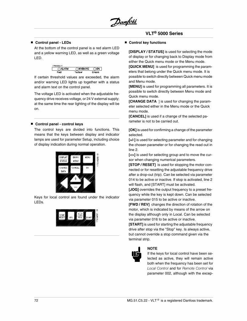
Control panel - LEDs
At the bottom of the control panel is a red alarm LEDand a yellow warning LED, as well as a green voltageLED.
If certain threshold values are exceeded, the alarmand/or warning LED lights up together with a statusand alarm text on the control panel.
The voltage LED is activated when the adjustable fre-quency drive receives voltage, or 24 V external supply;at the same time the rear lighting of the display will beon.
Control panel - control keys
The control keys are divided into functions. Thismeans that the keys between display and indicatorlamps are used for parameter Setup, including choiceof display indication during normal operation.
Keys for local control are found under the indicatorLEDs.
Control key functions
[DISPLAY / STATUS] is used for selecting the modeof display or for changing back to Display mode fromeither the Quick menu mode or the Menu mode.[QUICK MENU] is used for programming the param-eters that belong under the Quick menu mode. It ispossible to switch directly between Quick menu modeand Menu mode.[MENU] is used for programming all parameters. It ispossible to switch directly between Menu mode andQuick menu mode.[CHANGE DATA ] is used for changing the param-eter selected either in the Menu mode or the Quickmenu mode.[CANCEL] is used if a change of the selected pa-rameter is not to be carried out.
[OK] is used for confirming a change of the parameterselected.[+/-] is used for selecting parameter and for changingthe chosen parameter or for changing the read out inline 2.[<>] is used for selecting group and to move the cur-sor when changing numerical parameters.[STOP / RESET] is used for stopping the motor con-nected or for resetting the adjustable frequency driveafter a drop-out (trip). Can be selected via parameter014 to be active or inactive. If stop is activated, line 2will flash, and [START] must be activated.[JOG] overrides the output frequency to a preset fre-quency while the key is kept down. Can be selectedvia parameter 015 to be active or inactive.[FWD / REV] changes the direction of rotation of themotor, which is indicated by means of the arrow onthe display although only in Local. Can be selectedvia parameter 016 to be active or inactive.[START] is used for starting the adjustable frequencydrive after stop via the "Stop" key. Is always active,but cannot override a stop command given via theterminal strip.
NOTEIf the keys for local control have been se-lected as active, they will remain activeboth when the frequency has been set forLocal Control and for Remote Control viaparameter 002, although with the excep-
VLT® 5000 Series
72 MG.51.C5.22 - VLT is a registered Danfoss trademark.
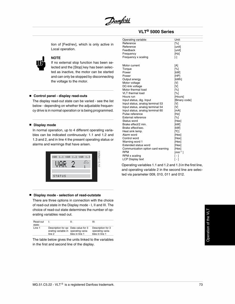
tion of [Fwd/rev], which is only active inLocal operation.
NOTEIf no external stop function has been se-lected and the [Stop] key has been selec-ted as inactive, the motor can be startedand can only be stopped by disconnectingthe voltage to the motor.
Control panel - display read-outs
The display read-out state can be varied - see the listbelow - depending on whether the adjustable frequen-cy drive is in normal operation or is being programmed.
Display mode
In normal operation, up to 4 different operating varia-bles can be indicated continuously: 1.1 and 1.2 and1.3 and 2, and in line 4 the present operating status oralarms and warnings that have arisen.
195NA
113.10VAR 2 SETUP
1
STATUS
VAR 1.1 VAR 1.2 VAR 1.3
Display mode - selection of read-outstate
There are three options in connection with the choiceof read-out state in the Display mode - I, II and III. Thechoice of read-out state determines the number of op-erating variables read out.
Read-outstate:
I: II: III:
Line 1 Description for op-erating variable inline 2
Data value for 3operating varia-bles in line 1
Description for 3operating varia-bles in line 1
The table below gives the units linked to the variablesin the first and second line of the display.
Operating variable: Unit:Reference [%]Reference [unit]Feedback [unit]Frequency [Hz]Frequency x scaling [-]
Motor current [A]Torque [%]Power [kW]Power [HP]Output energy [kWh]Motor voltage [V]DC-link voltage [V]Motor thermal load [%]VLT thermal load [%]Hours run [Hours]Input status, dig. Input [Binary code]Input status, analog terminal 53 [V]Input status, analog terminal 54 [V]Input status, analog terminal 60 [mA]Pulse reference [Hz]External reference [%]Status word [Hex]Brake effect/2 min. [kW]Brake effect/sec. [kW]Heat sink temp. [ºC]Alarm word [Hex]Control word [Hex]Warning word 1 [Hex]Extended status word [Hex]Communication option card warning [Hex]RPM [min-1 ]RPM x scaling [ - ]LCP Display text [ - ]
Operating variables 1.1 and 1.2 and 1.3 in the first line,and operating variable 2 in the second line are selec-ted via parameter 009, 010, 011 and 012.
VLT® 5000 Series
MG.51.C5.22 - VLT is a registered Danfoss trademark. 73
Ope
ratio
n of
the
VLT
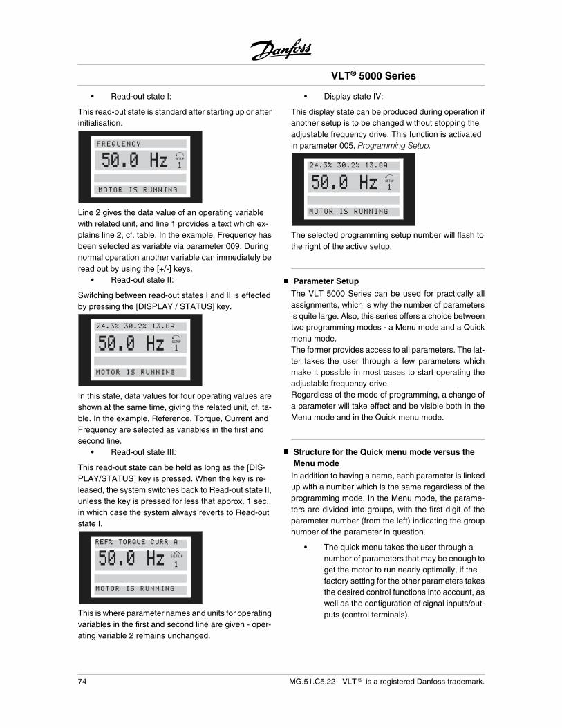
• Read-out state I:
This read-out state is standard after starting up or afterinitialisation.
50.0 HzFREQUENCY
MOTOR IS RUNNING
Line 2 gives the data value of an operating variablewith related unit, and line 1 provides a text which ex-plains line 2, cf. table. In the example, Frequency hasbeen selected as variable via parameter 009. Duringnormal operation another variable can immediately beread out by using the [+/-] keys.
• Read-out state II:
Switching between read-out states I and II is effectedby pressing the [DISPLAY / STATUS] key.
MOTOR IS RUNNING
50.0 Hz24.3% 30.2% 13.8A
In this state, data values for four operating values areshown at the same time, giving the related unit, cf. ta-ble. In the example, Reference, Torque, Current andFrequency are selected as variables in the first andsecond line.
• Read-out state III:
This read-out state can be held as long as the [DIS-PLAY/STATUS] key is pressed. When the key is re-leased, the system switches back to Read-out state II,unless the key is pressed for less that approx. 1 sec.,in which case the system always reverts to Read-outstate I.
50.0 Hz SETUP
1
MOTOR IS RUNNING
REF% TORQUE CURR A
This is where parameter names and units for operatingvariables in the first and second line are given - oper-ating variable 2 remains unchanged.
• Display state IV:
This display state can be produced during operation ifanother setup is to be changed without stopping theadjustable frequency drive. This function is activatedin parameter 005, Programming Setup.
MOTOR IS RUNNING
50.0 Hz24.3% 30.2% 13.8A
The selected programming setup number will flash tothe right of the active setup.
Parameter Setup
The VLT 5000 Series can be used for practically allassignments, which is why the number of parametersis quite large. Also, this series offers a choice betweentwo programming modes - a Menu mode and a Quickmenu mode.The former provides access to all parameters. The lat-ter takes the user through a few parameters whichmake it possible in most cases to start operating theadjustable frequency drive.Regardless of the mode of programming, a change ofa parameter will take effect and be visible both in theMenu mode and in the Quick menu mode.
Structure for the Quick menu mode versus theMenu mode
In addition to having a name, each parameter is linkedup with a number which is the same regardless of theprogramming mode. In the Menu mode, the parame-ters are divided into groups, with the first digit of theparameter number (from the left) indicating the groupnumber of the parameter in question.
• The quick menu takes the user through anumber of parameters that may be enough toget the motor to run nearly optimally, if thefactory setting for the other parameters takesthe desired control functions into account, aswell as the configuration of signal inputs/out-puts (control terminals).
VLT® 5000 Series
74 MG.51.C5.22 - VLT is a registered Danfoss trademark.
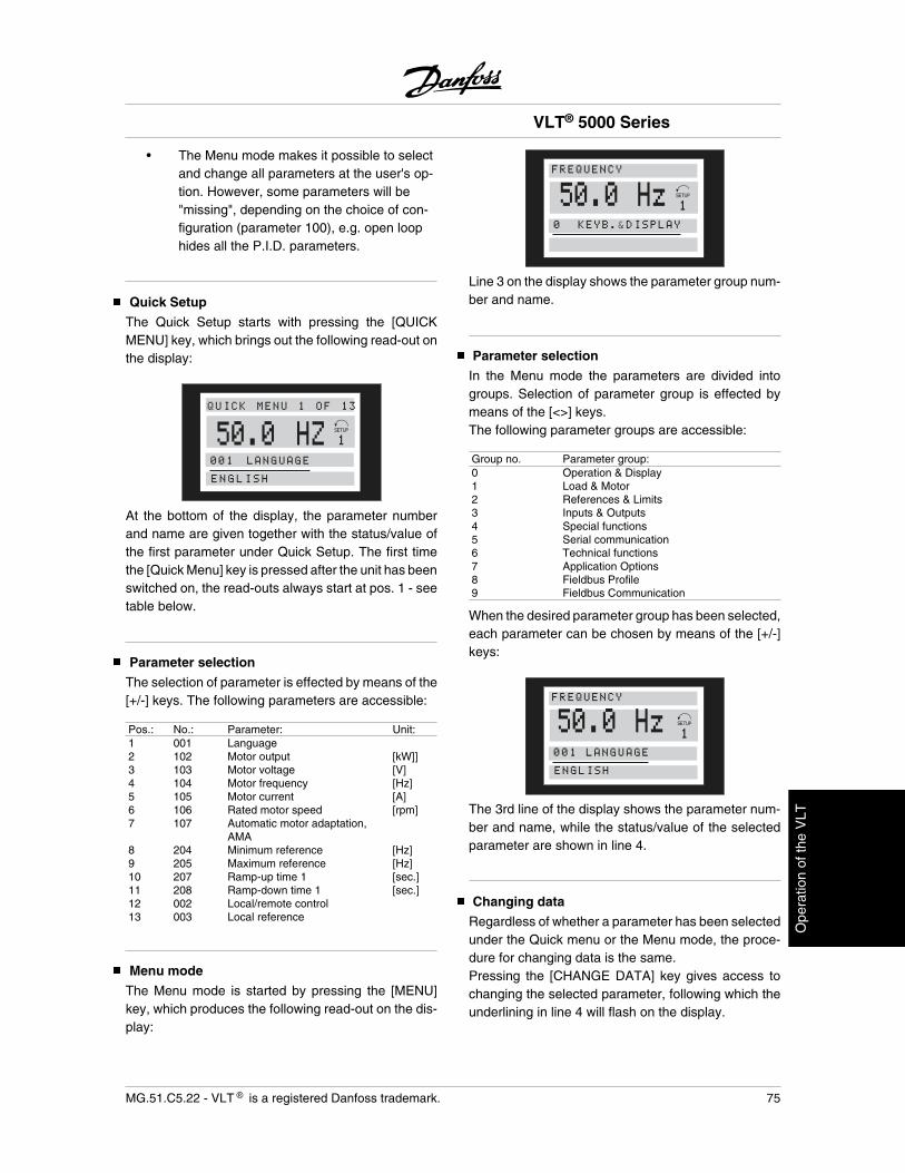
• The Menu mode makes it possible to selectand change all parameters at the user's op-tion. However, some parameters will be"missing", depending on the choice of con-figuration (parameter 100), e.g. open loophides all the P.I.D. parameters.
Quick Setup
The Quick Setup starts with pressing the [QUICKMENU] key, which brings out the following read-out onthe display:
50.0 HZ001 LANGUAGE
ENGLISH
QUICK MENU 1 OF 13
At the bottom of the display, the parameter numberand name are given together with the status/value ofthe first parameter under Quick Setup. The first timethe [Quick Menu] key is pressed after the unit has beenswitched on, the read-outs always start at pos. 1 - seetable below.
Parameter selection
The selection of parameter is effected by means of the[+/-] keys. The following parameters are accessible:
Pos.: No.: Parameter: Unit:1 001 Language 2 102 Motor output [kW]]3 103 Motor voltage [V]4 104 Motor frequency [Hz]5 105 Motor current [A]6 106 Rated motor speed [rpm]7 107 Automatic motor adaptation,
AMA8 204 Minimum reference [Hz]9 205 Maximum reference [Hz]10 207 Ramp-up time 1 [sec.]11 208 Ramp-down time 1 [sec.]12 002 Local/remote control 13 003 Local reference
Menu mode
The Menu mode is started by pressing the [MENU]key, which produces the following read-out on the dis-play:
50.0 HzFREQUENCY
0 KEYB.&DISPLAY
Line 3 on the display shows the parameter group num-ber and name.
Parameter selection
In the Menu mode the parameters are divided intogroups. Selection of parameter group is effected bymeans of the [<>] keys.The following parameter groups are accessible:
Group no. Parameter group:0 Operation & Display1 Load & Motor2 References & Limits3 Inputs & Outputs4 Special functions5 Serial communication6 Technical functions7 Application Options8 Fieldbus Profile9 Fieldbus Communication
When the desired parameter group has been selected,each parameter can be chosen by means of the [+/-]keys:
FREQUENCY
001 LANGUAGE
ENGLISH
50.0 Hz
The 3rd line of the display shows the parameter num-ber and name, while the status/value of the selectedparameter are shown in line 4.
Changing data
Regardless of whether a parameter has been selectedunder the Quick menu or the Menu mode, the proce-dure for changing data is the same.Pressing the [CHANGE DATA] key gives access tochanging the selected parameter, following which theunderlining in line 4 will flash on the display.
VLT® 5000 Series
MG.51.C5.22 - VLT is a registered Danfoss trademark. 75
Ope
ratio
n of
the
VLT
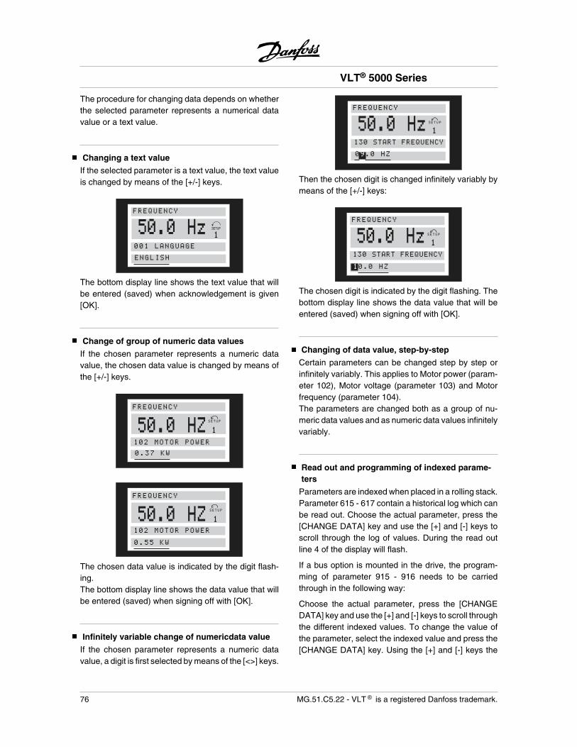
The procedure for changing data depends on whetherthe selected parameter represents a numerical datavalue or a text value.
Changing a text value
If the selected parameter is a text value, the text valueis changed by means of the [+/-] keys.
50.0 HzFREQUENCY
001 LANGUAGE
ENGLISH
The bottom display line shows the text value that willbe entered (saved) when acknowledgement is given[OK].
Change of group of numeric data values
If the chosen parameter represents a numeric datavalue, the chosen data value is changed by means ofthe [+/-] keys.
50.0 HZSETUP
1
FREQUENCY
102 MOTOR POWER0.37 KW
SETUP
1
50.0 HZFREQUENCY
102 MOTOR POWER
0.55 KW
SETUP
1
The chosen data value is indicated by the digit flash-ing.The bottom display line shows the data value that willbe entered (saved) when signing off with [OK].
Infinitely variable change of numericdata value
If the chosen parameter represents a numeric datavalue, a digit is first selected by means of the [<>] keys.
50.0 HzSETUP
1
FREQUENCY
130 START FREQUENCY
09.0 HZ
Then the chosen digit is changed infinitely variably bymeans of the [+/-] keys:
50.0 HzSETUP
1
FREQUENCY
130 START FREQUENCY
10.0 HZ
The chosen digit is indicated by the digit flashing. Thebottom display line shows the data value that will beentered (saved) when signing off with [OK].
Changing of data value, step-by-step
Certain parameters can be changed step by step orinfinitely variably. This applies to Motor power (param-eter 102), Motor voltage (parameter 103) and Motorfrequency (parameter 104).The parameters are changed both as a group of nu-meric data values and as numeric data values infinitelyvariably.
Read out and programming of indexed parame-ters
Parameters are indexed when placed in a rolling stack.Parameter 615 - 617 contain a historical log which canbe read out. Choose the actual parameter, press the[CHANGE DATA] key and use the [+] and [-] keys toscroll through the log of values. During the read outline 4 of the display will flash.
If a bus option is mounted in the drive, the program-ming of parameter 915 - 916 needs to be carriedthrough in the following way:
Choose the actual parameter, press the [CHANGEDATA] key and use the [+] and [-] keys to scroll throughthe different indexed values. To change the value ofthe parameter, select the indexed value and press the[CHANGE DATA] key. Using the [+] and [-] keys the
VLT® 5000 Series
76 MG.51.C5.22 - VLT is a registered Danfoss trademark.
value to be changed will flash. To accept the new set-ting, press [OK], to abort, press [CANCEL].
Manual initialization
The adjustable frequency drive can be initialized tofactory settings in two ways.
Initialization by parameter 620- Recommended initialization
• Select parameter 620
• Press [CHANGE]
• Select “Initialization”
• Press the [OK] key
• Cut off the mains supply and wait until thedisplay turns off.
• Reconnect the mains supply - the adjustablefrequency drive is now reset.
This parameter initializes all except:500 Serial communication address501 Baud rate for serial communication601-605 Operating data615-617 Fault logs
Manual initialization
• Disconnect from mains and wait until the dis-play turns off.
• Press the following keys at the same time:[Display/status][Change data][OK]
• Reconnecting the mains supply while press-ing the keys.
• Release the keys
• The adjustable frequency drive has nowbeen programmed for the factory setting.
This parameter initializes all except:600-605 Operating data
NOTESettings for serial communication andfault logs are reset.
VLT® 5000 Series
MG.51.C5.22 - VLT is a registered Danfoss trademark. 77
Ope
ratio
n of
the
VLT
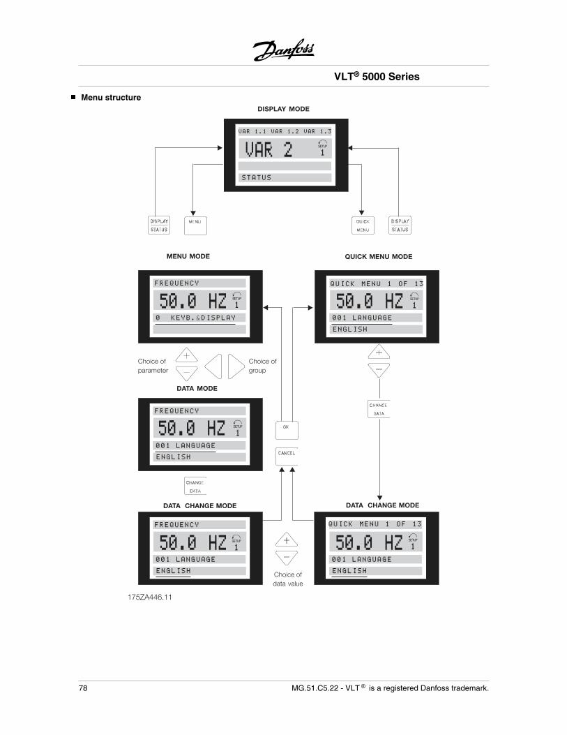
Menu structure
175ZA446.11
DISPLAY MODE
MENU MODE QUICK MENU MODE
DATA CHANGE MODE
▲▲
▲ ▲
▲
▲
▲▲
▲
Choice ofparameter
DATA MODE
Choice ofdata value
Choice ofgroup
VAR 2STATUS
VAR 1.1 VAR 1.2 VAR 1.3
50.0 HZFREQUENCY
0 KEYB.&DISPLAY
50.0 HZ001 LANGUAGE
ENGLISH
FREQUENCY
001 LANGUAGE
ENGLISH
50.0 HZFREQUENCY
001 LANGUAGE
ENGLISH
50.0 HZ001 LANGUAGE
ENGLISH
DATA CHANGE MODE
50.0 HZ
QUICK MENU 1 OF 13
QUICK MENU 1 OF 13
VLT® 5000 Series
78 MG.51.C5.22 - VLT is a registered Danfoss trademark.
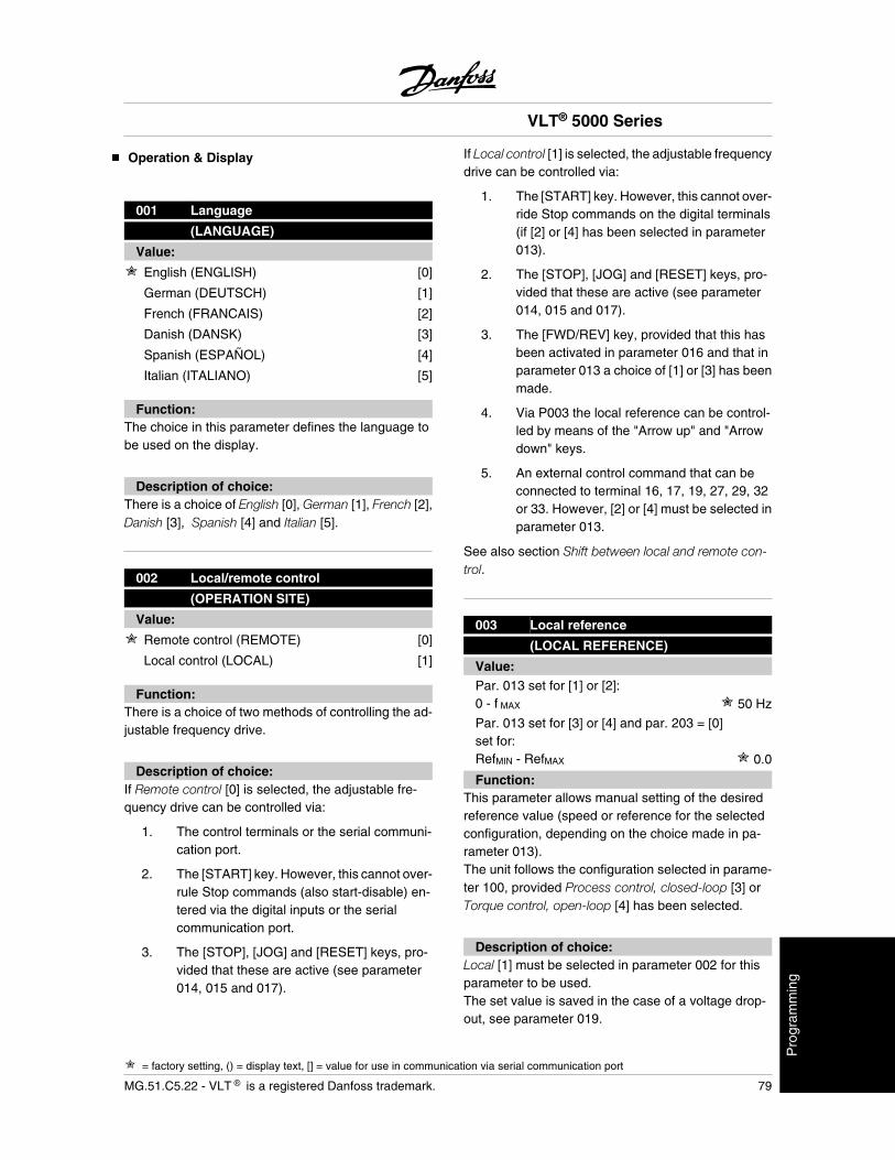
Operation & Display
001 Language
(LANGUAGE)
Value:
English (ENGLISH) [0]
German (DEUTSCH) [1]
French (FRANCAIS) [2]
Danish (DANSK) [3]
Spanish (ESPAÑOL) [4]
Italian (ITALIANO) [5]
Function:The choice in this parameter defines the language tobe used on the display.
Description of choice:There is a choice of English [0], German [1], French [2],Danish [3], Spanish [4] and Italian [5].
002 Local/remote control
(OPERATION SITE)
Value:
Remote control (REMOTE) [0]
Local control (LOCAL) [1]
Function:There is a choice of two methods of controlling the ad-justable frequency drive.
Description of choice:If Remote control [0] is selected, the adjustable fre-quency drive can be controlled via:
1. The control terminals or the serial communi-cation port.
2. The [START] key. However, this cannot over-rule Stop commands (also start-disable) en-tered via the digital inputs or the serialcommunication port.
3. The [STOP], [JOG] and [RESET] keys, pro-vided that these are active (see parameter014, 015 and 017).
If Local control [1] is selected, the adjustable frequencydrive can be controlled via:
1. The [START] key. However, this cannot over-ride Stop commands on the digital terminals(if [2] or [4] has been selected in parameter013).
2. The [STOP], [JOG] and [RESET] keys, pro-vided that these are active (see parameter014, 015 and 017).
3. The [FWD/REV] key, provided that this hasbeen activated in parameter 016 and that inparameter 013 a choice of [1] or [3] has beenmade.
4. Via P003 the local reference can be control-led by means of the "Arrow up" and "Arrowdown" keys.
5. An external control command that can beconnected to terminal 16, 17, 19, 27, 29, 32or 33. However, [2] or [4] must be selected inparameter 013.
See also section Shift between local and remote con-trol.
003 Local reference
(LOCAL REFERENCE)
Value:Par. 013 set for [1] or [2]:0 - f MAX 50 Hz
Par. 013 set for [3] or [4] and par. 203 = [0]set for:RefMIN - RefMAX 0.0
Function:This parameter allows manual setting of the desiredreference value (speed or reference for the selectedconfiguration, depending on the choice made in pa-rameter 013).The unit follows the configuration selected in parame-ter 100, provided Process control, closed-loop [3] orTorque control, open-loop [4] has been selected.
Description of choice:Local [1] must be selected in parameter 002 for thisparameter to be used.The set value is saved in the case of a voltage drop-out, see parameter 019.
VLT® 5000 Series
= factory setting, () = display text, [] = value for use in communication via serial communication port
MG.51.C5.22 - VLT is a registered Danfoss trademark. 79
Pro
gram
min
g
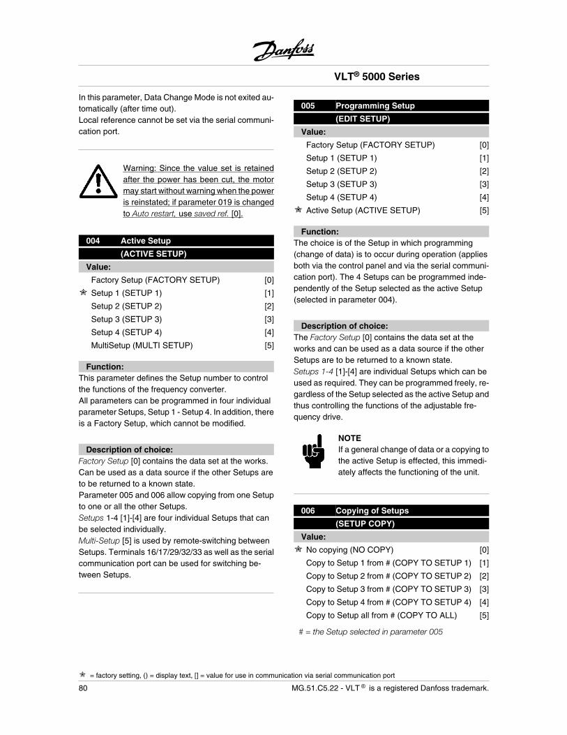
In this parameter, Data Change Mode is not exited au-tomatically (after time out).Local reference cannot be set via the serial communi-cation port.
Warning: Since the value set is retainedafter the power has been cut, the motormay start without warning when the poweris reinstated; if parameter 019 is changedto Auto restart, use saved ref. [0].
004 Active Setup
(ACTIVE SETUP)
Value:
Factory Setup (FACTORY SETUP) [0]
Setup 1 (SETUP 1) [1]
Setup 2 (SETUP 2) [2]
Setup 3 (SETUP 3) [3]
Setup 4 (SETUP 4) [4]
MultiSetup (MULTI SETUP) [5]
Function:This parameter defines the Setup number to controlthe functions of the frequency converter.All parameters can be programmed in four individualparameter Setups, Setup 1 - Setup 4. In addition, thereis a Factory Setup, which cannot be modified.
Description of choice:Factory Setup [0] contains the data set at the works.Can be used as a data source if the other Setups areto be returned to a known state.Parameter 005 and 006 allow copying from one Setupto one or all the other Setups.Setups 1-4 [1]-[4] are four individual Setups that canbe selected individually.Multi-Setup [5] is used by remote-switching betweenSetups. Terminals 16/17/29/32/33 as well as the serialcommunication port can be used for switching be-tween Setups.
005 Programming Setup
(EDIT SETUP)
Value:
Factory Setup (FACTORY SETUP) [0]
Setup 1 (SETUP 1) [1]
Setup 2 (SETUP 2) [2]
Setup 3 (SETUP 3) [3]
Setup 4 (SETUP 4) [4]
Active Setup (ACTIVE SETUP) [5]
Function:The choice is of the Setup in which programming(change of data) is to occur during operation (appliesboth via the control panel and via the serial communi-cation port). The 4 Setups can be programmed inde-pendently of the Setup selected as the active Setup(selected in parameter 004).
Description of choice:The Factory Setup [0] contains the data set at theworks and can be used as a data source if the otherSetups are to be returned to a known state.Setups 1-4 [1]-[4] are individual Setups which can beused as required. They can be programmed freely, re-gardless of the Setup selected as the active Setup andthus controlling the functions of the adjustable fre-quency drive.
NOTEIf a general change of data or a copying tothe active Setup is effected, this immedi-ately affects the functioning of the unit.
006 Copying of Setups
(SETUP COPY)
Value:
No copying (NO COPY) [0]
Copy to Setup 1 from # (COPY TO SETUP 1) [1]
Copy to Setup 2 from # (COPY TO SETUP 2) [2]
Copy to Setup 3 from # (COPY TO SETUP 3) [3]
Copy to Setup 4 from # (COPY TO SETUP 4) [4]
Copy to Setup all from # (COPY TO ALL) [5]
# = the Setup selected in parameter 005
VLT® 5000 Series
= factory setting, () = display text, [] = value for use in communication via serial communication port
80 MG.51.C5.22 - VLT is a registered Danfoss trademark.
Function:A copy is made from the Setup selected in parameter005 to one of the other Setups or to all the other Setupssimultaneously. The setup copying function does notcopy parameter 001, 004, 005, 500 and 501.
Copying is only possible in Stop Mode (motor stoppedon a Stop command).
Description of choice:The copying starts when the desired copying functionhas been entered and confirmed by pressing the [OK]key.The display indicates when copying is in progress.
007 LCP copy
(LCP COPY)
Value:
No copying (NO COPY) [0]
Upload all parameters (UPLOAD ALL PAR-AM) [1]
Download all parameters (DOWNLOAD ALL) [2]
Download power-independent par.(DOWNLOAD SIZE INDEP.) [3]
Function:LCP copy is used if it is desired to use the integratedcopying function of the control panel. The control panelis detachable. You can therefore easily copy parame-ter value(s) from one to another.
Description of choice:Select Upload all parameters [1] if all parameter valuesare to be transmitted to the control panel.Select Download all parameters [2] if all transmittedparameter values are to be copied to the adjustablefrequency drive on which the control panel has beenmounted.Select Download power-independent par. [3] if only thepower-independent parameters are to be downloaded.This is used if downloading to an adjustable frequencydrive that has a different rated power that the one fromwhere the parameter Setup originates.Please note that the power-dependent parameter102-106 must be programmed after copying.
NOTEUploading/Downloading can only be car-ried out in the Stop mode.
008 Display scaling of motor frequency
(FREQUENCY SCALE)
Value:0.01 - 500.00 1
Function:This parameter chooses the factor to be multiplied bythe motor frequency, fM , for presentation in the dis-play, when parameters 009-012 have been set forFrequency x Scaling [5].
Description of choice:Set the desired scaling factor.
009 Display line 2 (DISPLAY LINE 2)
Value:
No readout (NONE) [0]
Reference [%] (REFERENCE [%]) [1]
Reference [unit] (REFERENCE [UNIT]) [2]
Feedback [unit] (FEEDBACK [UNIT]) [3]
Frequency [Hz] (FREQUENCY [Hz]) [4]
Frequency x Scaling [-](FREQUENCY X SCALE) [5]
Motor current [A] (MOTOR CURRENT [A]) [6]
Torque [%] (TORQUE [%]) [7]
Power [kW] (POWER [kW]) [8]
Power [HP] (POWER [hp] [US]) [9]
Output energy [kWh](OUTPUT ENERGY [kWh]) [10]
Motor voltage [V] (MOTOR VOLTAGE [V]) [11]
DC link voltage [V] (DC LINK VOLTAGE [V]) [12]
Thermal load, motor [%](MOTOR THERMAL [%]) [13]
Thermal load, VLT [%] (VLT THERMAL [%]) [14]
Hours run [Hours] (RUNNING HOURS) [15]
Digital input [Binary code](DIGITAL INPUT [BIN]) [16]
Analog input 53 [V] (ANALOG INPUT 53 [V]) [17]
VLT® 5000 Series
= factory setting, () = display text, [] = value for use in communication via serial communication port
MG.51.C5.22 - VLT is a registered Danfoss trademark. 81
Pro
gram
min
g
Analog input 54 [V] (ANALOG INPUT 54 [V]) [18]
Analog input 60 [mA](ANALOG INPUT 60 [mA]) [19]
Pulse reference [Hz] (PULSE REF. [Hz]) [20]
External reference [%] (EXTERNAL REF[%]) [21]
Status word [Hex] (STATUS WORD [HEX]) [22]
Brake effect/2 min. [KW](BRAKE ENERGY/2 min) [23]
Brake effect/sec. [kW] (BRAKE ENERGY/s) [24]
Heat sink temp. [°C] (HEATSINK TEMP [°C]) [25]
Alarm word [Hex] (ALARM WORD [HEX]) [26]
Control word [Hex](CONTROL WORD [HEX]) [27]
Warning word 1 [Hex](WARNING WORD 1 [HEX]) [28]
Warning word 2 [Hex](WARNING WORD 2 [HEX]) [29]
Communication option card warning(Comm opt warn [hex]) [30]
RPM [min-1] (MOTOR RPM [RPM]) [31]
RPM x scaling [-] (MOTOR RPM x SCALE) [32]
LCP Display text (FREE PROG. ARRAY) [33]
Function:This parameter allows a choice of the data value to bedisplayed in line 2 of the display.Parameters 010-012 enable the use of three additionaldata values to be displayed in line 1.
Description of choice:No readout switches of the readout.Reference [%] corresponds to the total reference(sum of digital/analog/preset/bus/freeze ref./catch-upand slow-down).Reference [unit] gives the status value of terminals17/29/53/54/60 using the unit stated on the basis ofconfiguration in parameter 100 (Hz, Hz and rpm).Feedback [unit] gives the status value of terminal33/53/60 using the unit/scale selected in parameter414, 415 and 416.Frequency [Hz] gives the motor frequency, i.e. theoutput frequency from the adjustable frequency drive.Frequency x Scaling [-] corresponds to the presentmotor frequency fM (without resonance dampening)multiplied by a factor (scaling) set in parameter 008.
Motor current [A] states the phase current of the mo-tor measured as effective value.Torque [%] gives the current motor load in relation tothe rated motor torque.Power [kW] states the actual power consumed by themotor in kW.Power [HP] states the actual power consumed by themotor in HP.Output energy [kWh] states the energy consumed bythe motor since the latest reset was made in parameter618.Motor voltage [V] states the voltage supplied to themotor.DC link voltage [V] states the intermediate circuitvoltage in the adjustable frequency drive.Thermal load, motor [%] states the calculated/esti-mated thermal load on the motor. 100% is the cut-outlimit.Thermal load, VLT [%] states the calculated/estima-ted thermal load on the adjustable frequency drive.100% is the cut-out limit.Hours run [Hours] states the number of hours that themotor has run since the latest reset in parameter 619.Digital input [Binary code] states the signal statesfrom the 8 digital terminals (16, 17, 18, 19, 27, 29, 32and 33) Input 16 corresponds to the bit at the far left.'0' = no signal, '1' = connected signal.Analog input 53 [V] states the signal value on termi-nal 53.Analog input 54 [V] states the signal value on termi-nal 54.Analog input 60 [V] states the signal value on termi-nal 60.Pulse reference [Hz] states the possible frequency inHz connected to the terminals 17 or 29.External reference [%] gives the sum of the externalreference as a percentage (the sum of analog/pulse/bus).Status word [Hex] gives the status word sent via theserial communication port in Hex code from the ad-justable frequency drive.Brake power/2 min. [KW] states the brake powertransferred to an external brake resistor. The meanpower is calculated continuously for the latest 120 sec-onds.It is assumed that a resistor value has been entered inparameter 401.
VLT® 5000 Series
= factory setting, () = display text, [] = value for use in communication via serial communication port
82 MG.51.C5.22 - VLT is a registered Danfoss trademark.
Brake power/sec. [kW] states the present brake pow-er transferred to an external brake resistor. Stated asan instantaneous value.It is assumed that a resistor value has been entered inparameter 401.Heat sink temp. [°C] states the present heat sink tem-perature of the adjustable frequency drive. The cut-outlimit is 90 ± 5°C; cutting back in occurs at 60 ± 5°C.Alarm word [Hex] indicates one or several alarms ina Hex code. See Alarm word.Control word. [Hex] indicates the control word for theadjustable frequency drive. See Serial communicationin the Design Guide.Warning word 1. [Hex] indicates one or more warn-ings in a Hex code. See Warning word.Warning word 2. [Hex] indicates one or more statusstates in a Hex code. See Warning word.Communication option card warning [Hex] gives awarning word if there is a fault on the communicationbus. Is only active if communication options have beeninstalled. Without communication options, 0 Hex isdisplayed.
RPM [min-1] indicates the motor speed. In speedclosed loop, the value is measured. In other modes thevalue is calculated based on the motor slip.RPM x scaling [-] indicates the motor RPM multipliedby a factor set in parameter 008.LCP display text shows the text programmed in pa-rameter 553 Display text 1 and 554 Display text 2 viaLCP or the serial communication port. Not possible inparameter 011-012.Display text 1 is only shown in full length if par 011 and012 are set to None [0].
010 Display line 1.1 (DISPLAY LINE 1.1)011 Display line 1.2 (DISPLAY LINE 1.2)012 Display line 1.3 (DISPLAY LINE 1.3)
Value:See parameter 009.
Function:Parameter 010 - 012 enable a choice of three differentdata values to be shown on the display, line 1 position1, line 1 position 2 and line 1 position 3, respectively.For display read-outs, press the [DISPLAY/STATUS]button.The reading can be switched off.
Description of choice:The factory setting for each parameter is the following:
Par. 010 Reference [%]Par. 011 Motor current [A]Par. 012 Power [kW]
013Local Control/Configuration asparameter 100
(LOCAL CTRL/CONFIG.)
Value:
Local not active (DISABLE) [0]
LCP control and open loop.(LCP CTRL/OPEN LOOP) [1]
LCP digital control and open loop.(LCP+DIG CTRL/OP.LOOP) [2]
LCP control/as parameter 100.(LCP CTRL/AS P100) [3]
LCP digital control/as parameter 100.(LCP+DIG CTRL/AS P100) [4]
Function:This is where the desired function is to be selected ifLocal control has been chosen in parameter 002.See also the description of parameter 100.
Description of choice:If Local not active [0] is selected, a possible setting ofLocal reference via parameter 003 is blocked.It is only possible to change to Local not active [0] fromone of the other setting options in parameter 013,when the adjustable frequency drive has been set toRemote control [0] in parameter 002.
LCP control and open loop [1] is used when the speedis to be adjustable (in Hz) via parameter 003, when theadjustable frequency drive has been set to Local con-trol [1] in parameter 002.
If parameter 100 has not been set to Speed controlopen loop [0], switch to Speed control open loop [0]
LCP digital control and open loop [2] functions as LCPcontrol and open loop [1], the only difference being thatwhen parameter 002 has been set to Local operation[1], the motor is controlled via the digital inputs, ac-cording to the list in section Shift between local andremote control.
VLT® 5000 Series
= factory setting, () = display text, [] = value for use in communication via serial communication port
MG.51.C5.22 - VLT is a registered Danfoss trademark. 83
Pro
gram
min
g
LCP control/as parameter 100 [3] is selected if the ref-erence is to be set via parameter 003.
LCP digital control/as parameter 100 [4] functions asLCP control/as parameter 100 [3], although, when pa-rameter 002 has been set to Local operation [1], themotor may be controlled via the digital inputs in ac-cordance with the list in section Shift between local andremote control .
NOTEShift from Remote control to LCP digitalcontrol and open loop:
The present motor frequency and direction of rotationmust be maintained. If the present direction of rotationdoes not correspond to the reversing signal (negativereference), the motor frequency fM will be set at 0 Hz.
Shift from LCP digital control and open loop to Remotecontrol:The selected configuration (parameter 100) will be ac-tive. Shifts are effected without any abrupt movement.
Shift from Remote control to LCP control/as parameter100 or LCP digital control/as parameter 100.The present reference will be maintained. If the refer-ence signal is negative, the local reference will be setat 0.
Shift from LCP control/as parameter 100 or LCP re-mote control as parameter 100 to Remote control.The reference will be replaced by the active referencesignal from the remote control.
014 Local stop
(LOCAL STOP)
Value:
Disable (DISABLE) [0]
Enable (ENABLE) [1]
Function:This parameter disables/enables the local stop func-tion from the LCP.This key is used when parameter 002 has been set forRemote control [0] or Local [1].
Description of choice:If Disable [0] is selected, the [STOP] key will be inac-tive.
NOTEIf Enable is selected, the [STOP] key over-rules all Start commands.
015 Local jog (LOCAL JOGGING)
Value:
Not possible (DISABLE) [0]
Possible (ENABLE) [1]
Function:This parameter enables/disables the local jog functionon the LCP.The key is used when parameter 002 has been set forRemote control [0] or Local [1].
Description of choice:If Disable [0] is selected, the [JOG] key will be inactive.
016 Local reversing
(LOCAL REVERSING)
Value:
Not possible (DISABLE) [0]
Possible (ENABLE) [1]
Function:This parameter enables/disables the reversing func-tion on the LCP.This key can only be used if parameter 002 has beenset to Local operation [1] and parameter 013 to LCPcontrol [3].
Description of choice:If Disable [0] is selected, the [FWD/REV] key will beinactive.See parameter 200.
VLT® 5000 Series
= factory setting, () = display text, [] = value for use in communication via serial communication port
84 MG.51.C5.22 - VLT is a registered Danfoss trademark.
017 Local reset of trip (LOCAL RESET)
Value:
Not possible (DISABLE) [0]
Possible (ENABLE) [1]
Function:In this parameter, the reset function can be selected/removed from the keyboard.This key can be used when parameter 002 has beenset for Remote control [0] or Local control [1].
Description of choice:If Disable [0] is selected in this parameter, the [RESET]key will be inactive.
NOTEOnly select Disable [0] if an external resetsignal has been connected via the digitalinputs.
018 Lock for data change
(DATA CHANGE LOCK)
Value:
Not locked (NOT LOCKED) [0]
Locked (LOCKED) [1]
Function:In this parameter, the software can "lock" the control,which means that data changes cannot be made viaLCP (however, this is still possible via the serial com-munication port).
Description of choice:If Locked [1] is selected, data changes cannot bemade.
019Operating state at Power up, local con-trol
(POWER UP ACTION)
Value:
Auto restart, use saved ref. (AUTO RE-START) [0]
Forced stop, use saved ref. (LOCAL=STOP) [1]
Forced stop, set ref. to 0(LOCAL=STOP, REF=0) [2]
Function:Setting of the operating mode when the mains voltageis reconnected.This function can only be active in connection withLocal control [1] in parameter 002.
Description of choice:Auto restart, use saved ref. [0] is selected if the unit isto start up with the same local reference (set in pa-rameter 003) and the same start/stop conditions (givenvia the [START/STOP] keys) that the adjustable fre-quency drive had before it was switched off.Forced stop, use saved ref. [1] is used if the unit is toremain stopped when the mains voltage is connected,until the [START] key is pressed. After the start com-mand, the local reference used is set in parameter 003.Forced stop, set ref. to 0 [2] is selected if the unit is toremain stopped when the mains voltage is connected.Local reference (parameter 003) is reset.
NOTEIn remote controlled operation (parameter002), the start/stop condition at power upwill depend on the external control sig-nals. If Pulse start [2] is selected in param-eter 302, the motor will remain stopped atpower-up.
027 Warning readout line
(WARNING READOUT)
Value:
Warning in line 1/2 [0]
Warning in line 3/4 [1]
VLT® 5000 Series
= factory setting, () = display text, [] = value for use in communication via serial communication port
MG.51.C5.22 - VLT is a registered Danfoss trademark. 85
Pro
gram
min
g
Function:In this parameter it is decided in which line the warningis to appear in display mode. In programming mode(Menu or Quick menu) the warning will appear in line1/2 to avoid disturbance of the programming.
Description of choice:Select the readout line.
VLT® 5000 Series
86 MG.51.C5.22 - VLT is a registered Danfoss trademark.
Load and motor
100 Configuration
(CONFIG. MODE)
Value:
Speed control, open loop(SPEED OPEN LOOP) [0]
Speed control, closed loop(SPEED CLOSED LOOP) [1]
Process control, closed loop(PROCESS CLOSED LOOP) [3]
Torque control, open loop(TORQUE OPEN LOOP) [4]
Torque control, speed feedback(TORQUE CONTROL SPEED) [5]
Function:This parameter is used for selecting the configurationto which the adjustable frequency drive is to be adap-ted. This makes adaptation to a given application sim-ple, because the parameters that are not used in thegiven configuration are covered up (not active). Bychanging between the different application configura-tions, bumpless transfer (frequency only) is ensured.
Description of choice:IfSpeed control, open loop [0] is selected, a normalspeed control (without feedback signal) is obtained,but with automatic slip compensation, ensuring a near-ly constant speed at varying loads.Compensations are active, but may be disabled as re-quired in parameter group 100.
IfSpeed control, closed loop [1] is selected, a full hold-ing torque is obtained at 0 rpm, in addition to increasedspeed accuracy. A feedback signal must be providedand the PID regulator must be set.
IfProcess control, closed loop [3] is selected, the in-ternal process regulator will be activated, thereby en-abling accurate control of a process with respect to agiven process signal. The process signal can be setusing the actual process unit or as a percentage. Afeedback signal must be supplied from the process,and the process setpoint must be adjusted.
IfTorque control, open loop [4] is selected, the speedis regulated and the torque is kept constant. This isdone without a feedback signal, since VLT 5000 ac-
curately calculates the torque on the basis of the cur-rent measurement.
IfTorque control, speed feedback [5] is selected, anencoder speed feedback signal must be connected tothe digital terminals 32/33.
Parameter 205 Maximum reference and parameter 415Maximum feedback must be adapted to the applicationif [1], [3], [4] or [5] is selected.
101 Torque characteristics
(TORQUE CHARACT)
Value:
High-constant torque (H-CONSTANT TOR-QUE) [1]
High-variable torque low (H-VAR.TORQ.:LOW) [2]
High-variable torque medium(H-VAR.TORQ.: MEDIUM) [3]
High-variable torque high(H-VAR.TORQ.: HIGH) [4]
High-special motor characteristics(H-SPEC.MOTOR CHARACT) [5]
High-variable torque with low starting torque(H-VT LOW W. CT-START) [6]
High-variable torque with medium startingtorque(H-VT MED W. CT-START) [7]
High-variable torque with high starting torque(H-VT HIGH W. CT-START) [8]
Normal-constant torque(N-CONSTANT TORQUE) [11]
Normal-variable torque low(N-VAR.TORQ.: LOW) [12]
Normal-variable torque medium(N-VAR.TORQ.: MEDIUM) [13]
Normal-variable torque high(N-VAR.TORQ.: HIGH) [14]
Normal-special motor characteristics(N-SPEC.MOTOR CHARACT) [15]
Normal-variable torque with low constantstarting torque(N-VT LOW W. CT-START) [16]
VLT® 5000 Series
= factory setting, () = display text, [] = value for use in communication via serial communication port
MG.51.C5.22 - VLT is a registered Danfoss trademark. 87
Pro
gram
min
g
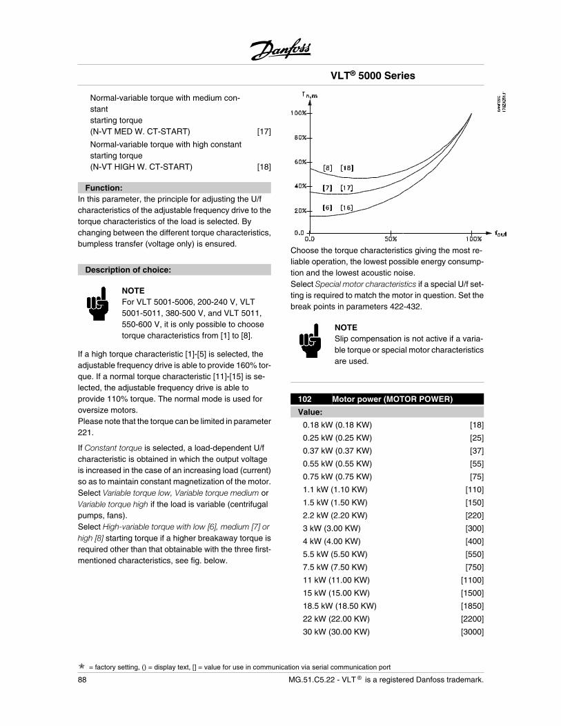
Normal-variable torque with medium con-stantstarting torque(N-VT MED W. CT-START) [17]
Normal-variable torque with high constantstarting torque(N-VT HIGH W. CT-START) [18]
Function:In this parameter, the principle for adjusting the U/fcharacteristics of the adjustable frequency drive to thetorque characteristics of the load is selected. Bychanging between the different torque characteristics,bumpless transfer (voltage only) is ensured.
Description of choice:
NOTEFor VLT 5001-5006, 200-240 V, VLT5001-5011, 380-500 V, and VLT 5011,550-600 V, it is only possible to choosetorque characteristics from [1] to [8].
If a high torque characteristic [1]-[5] is selected, theadjustable frequency drive is able to provide 160% tor-que. If a normal torque characteristic [11]-[15] is se-lected, the adjustable frequency drive is able toprovide 110% torque. The normal mode is used foroversize motors.Please note that the torque can be limited in parameter221.
If Constant torque is selected, a load-dependent U/fcharacteristic is obtained in which the output voltageis increased in the case of an increasing load (current)so as to maintain constant magnetization of the motor.Select Variable torque low, Variable torque medium orVariable torque high if the load is variable (centrifugalpumps, fans).Select High-variable torque with low [6], medium [7] orhigh [8] starting torque if a higher breakaway torque isrequired other than that obtainable with the three first-mentioned characteristics, see fig. below.
Choose the torque characteristics giving the most re-liable operation, the lowest possible energy consump-tion and the lowest acoustic noise.Select Special motor characteristics if a special U/f set-ting is required to match the motor in question. Set thebreak points in parameters 422-432.
NOTESlip compensation is not active if a varia-ble torque or special motor characteristicsare used.
102 Motor power (MOTOR POWER)
Value:
0.18 kW (0.18 KW) [18]
0.25 kW (0.25 KW) [25]
0.37 kW (0.37 KW) [37]
0.55 kW (0.55 KW) [55]
0.75 kW (0.75 KW) [75]
1.1 kW (1.10 KW) [110]
1.5 kW (1.50 KW) [150]
2.2 kW (2.20 KW) [220]
3 kW (3.00 KW) [300]
4 kW (4.00 KW) [400]
5.5 kW (5.50 KW) [550]
7.5 kW (7.50 KW) [750]
11 kW (11.00 KW) [1100]
15 kW (15.00 KW) [1500]
18.5 kW (18.50 KW) [1850]
22 kW (22.00 KW) [2200]
30 kW (30.00 KW) [3000]
VLT® 5000 Series
= factory setting, () = display text, [] = value for use in communication via serial communication port
88 MG.51.C5.22 - VLT is a registered Danfoss trademark.
37 kW (37.00 KW) [3700]
45 kW (45.00 KW) [4500]
55 kW (55.00 KW) [5500]
75 kW (75.00 KW) [7500]
90 kW (90.00 KW) [9000]
110 kW (110.00 KW) [11000]
132 kW (132.00 KW) [13200]
160 kW (160.00 KW) [16000]
200 kW (200.00 KW) [20000]
250 kW (250.00 KW) [25000]
280 kW (280.00 KW) [28000]
315 kW (315.00 KW) [31500]
355 kW (355.00 KW) [35500]
400 kW (400.00 KW) [40000]
450 kW (450.00 KW) [45000]
500 kW (500.00 KW) [50000]
530 kW (530.00 KW) [53000]
560 kW (560.00 KW) [56000]
630 kW (630.00 KW) [63000]
Depends on the unit
Function:Selects the kW value that corresponds to the ratedpower of the motor.A rated kW value has been selected from the factorythat depends on the unit size.
Description of choice:Select a value that equals the nameplate data on themotor. There are 4 possible undersizes or 1 oversizein comparison with the factory setting.Also, alternatively it is possible to set the value for mo-tor power as an infinitely variable value.The set value automatically changes the values of themotor parameters in parameter 108-118.
NOTEIf the setting in parameter 102-109 ischanged, parameter 110-118 will return tofactory setting. If using special motor char-acteristics a change in parameter 102-109affects parameter 422.
103 Motor voltage (MOTOR VOLTAGE)
Value:
200 V [200]
208 V [208]
220 V [220]
230 V [230]
240 V [240]
380 V [380]
400 V [400]
415 V [415]
440 V [440]
460 V [460]
480 V [480]
500 V [500]
550 V [550]
575 V [575]
660 V [660]
690 V [690]
Depends on the unit.
Function:Select a value that equals the nameplate data on themotor.
NOTEThe motor will always see the peak volt-age, corresponding to the connected sup-ply voltage. In case of regenerative oper-ation, the voltage can be higher.
Description of choice:Select a value that equals the nameplate data on themotor, regardless of the AC line voltage of the adjust-able frequency drive. Furthermore, it is also possibleto set the value of the motor voltage at an infinitelyvariable rate.The value set automatically changes values for themotor parameters in parameters 108-118.For 87 Hz operation with 230/400 V motors, set thenameplate data for 230 V. Adapt parameter 202 Out-put frequency high limit and parameter 205 Maximumreference to the 87 Hz application.
VLT® 5000 Series
= factory setting, () = display text, [] = value for use in communication via serial communication port
MG.51.C5.22 - VLT is a registered Danfoss trademark. 89
Pro
gram
min
g
NOTEIf a delta connection is used, the ratedmotor frequency for the delta connectionmust be selected.
NOTEIf the setting in parameter 102-109 ischanged, the parameters 110-118 will re-turn to the factory setting. If using specialmotor characteristics, a change in param-eter 102-109 affects parameter 422.
104 Motor frequency
(MOTOR FREQUENCY)
Value:
50 Hz (50 HZ) [50]
60 Hz (60 HZ) [60]
Max. motor frequency 1000 Hz.
Function:This is where the rated motor frequency fM,N is selected(nameplate data).
Description of choice:Select a value that equals the nameplate data on themotor.It is also possible to set the value for motor frequencyat an infinitely variable rate, see chapter Operation ofthe adjustable frequency driveIf a value different from 50 Hz or 60 Hz is selected, itis necessary to correct parameters 108 and 109.For 87 Hz operation with 230/400 V motors, set thenameplate data for 230 V. Adapt parameter 202 Out-put frequency high limit and parameter 205 Maximumreference to the 87 Hz application.
NOTEIf a delta connection is used, the ratedmotor frequency for the delta connectedmust be selected.
NOTEIf the setting in parameter 102-109 ischanged, the parameters 110-118 will re-turn to the factory setting. If using special
motor characteristics, a change in param-eter 102-109 affects parameter 422.
105 Motor current (MOTOR CURRENT)
Value:
0.01 - IVLT,MAX [0.01 - XXX.X]
Depends on the choice of motor.
Function:The rated motor current IM,N forms part of the adjust-able frequency drive calculations i.a. of torque andmotor thermal protection.
Description of choice:Select a value that equals the nameplate data on themotor.Enter the value in Ampere.
NOTEIt is important to enter the correct value,
since this forms part of the VVCplus controlfeature.
NOTEIf the setting in parameter 102-109 ischanged, the parameters 110-118 will re-turn to factory setting. If using special mo-tor characteristics a change in parameter102-109 affects parameter 422.
106 Rated motor speed
(MOTOR NOM. SPEED)
Value:
100 - 60000 rpm (rpm) [100 - 60000]
Depends on the choice of motor.
Function:This is where the value is selected that corresponds tothe rated motor speed nM,N, which can be seen fromthe nameplate data.
Description of choice:The rated motor speed nM,N is used i.a. for calculatingthe optimal slip compensation.
VLT® 5000 Series
= factory setting, () = display text, [] = value for use in communication via serial communication port
90 MG.51.C5.22 - VLT is a registered Danfoss trademark.
NOTEIt is important to enter the correct value,
since this forms part of the VVCplus controlfeature. The max. value equals fM,N x 60.Set fM,N in parameter 104.
NOTEIf the setting in parameter 102-109 ischanged, the parameters 110-118 will re-turn to factory setting. If using special mo-tor characteristics a change in parameter102-109 affects parameter 422.
107 Automatic motor adaptation, AMA
(AUTO MOTOR ADAPT)
Value:
Adaptation off (OFF) [0]
Adaptation on, RS and XS (ENABLE (RS,XS)) [1]
Adaptation on, RS (ENABLE (RS)) [2]
Function:If this function is used, the adjustable frequency driveautomatically sets the necessary control parameters(parameters 108/109) with the motor stationary. Auto-matic motor adaptation ensures optimum use of themotor.For the best possible adaptation of the adjustable fre-quency drive, it is recommended to run AMA on a coldmotor.
The AMA function is activated by pressing the[START] key after selecting [1] or [2].See also section Automatic motor adaptation.The section Automatic motor adaption, AMA, via VLTsoftware dialog shows how automatic motor adaptationcan be activated by means of VLT Software Dialog.After a normal sequence, the display will read "ALARM21". Press the [STOP/RESET] key. The adjustablefrequency drive is now ready for operation.
Description of choice:Select Enable, RS and XS [1] if the adjustable frequencydrive is to be able to carry out automatic motor adap-tation of both the stator resistance RS and the statorreactance XS.
Select Optimisation on, RS [2] if a reduced test is to becarried out, in which only the ohmic resistance in thesystem is determined.
NOTEIt is important to set motor parameters102-106 correctly, since these form part ofthe AMA algorithm. In most applications,correct entering of motor parameters102-106 is sufficient. For optimum dynam-ic motor adaptation, an AMA must be car-ried out.Motor adaptation may take up to 10 mi-nutes, depending on the output of the mo-tor in question.
NOTEThere must not be any externally gener-ating torque during automatic motor adap-tation.
NOTEIf the setting in parameter 102-109 ischanged, the parameters 110-118 will re-turn to factory setting. If using special mo-tor characteristics a change in parameter102-109 affects parameter 422.
108 Stator resistor (STATOR RESIST)
Value:
Depends on the choice of motor
Function:After setting motor data in parameters 102-106, anumber of adjustments of various parameters aremade automatically, including the stator resistanceRS. A manually entered RS must apply to a cold motor.The shaft performance can be improved by fine-tuningRS and XS, see procedure below.
Description of choice:RS can be set as follows:
1. Automatic motor adaptation, where the ad-justable frequency drive measures on themotor to determine the value. All compensa-tions are reset to 100%.
VLT® 5000 Series
= factory setting, () = display text, [] = value for use in communication via serial communication port
MG.51.C5.22 - VLT is a registered Danfoss trademark. 91
Pro
gram
min
g
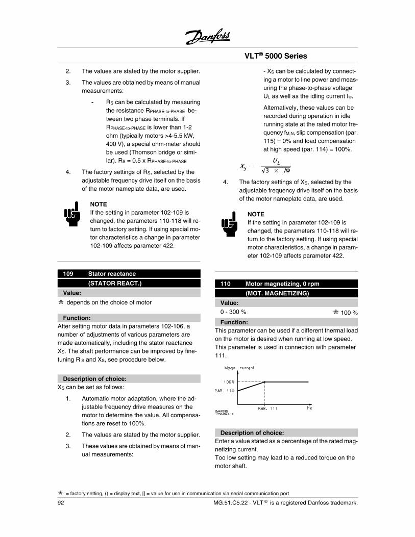
2. The values are stated by the motor supplier.
3. The values are obtained by means of manualmeasurements:
- RS can be calculated by measuringthe resistance RPHASE-to-PHASE be-tween two phase terminals. IfRPHASE-to-PHASE is lower than 1-2ohm (typically motors >4-5.5 kW,400 V), a special ohm-meter shouldbe used (Thomson bridge or simi-lar). RS = 0.5 x RPHASE-to-PHASE
4. The factory settings of RS, selected by theadjustable frequency drive itself on the basisof the motor nameplate data, are used.
NOTEIf the setting in parameter 102-109 ischanged, the parameters 110-118 will re-turn to factory setting. If using special mo-tor characteristics a change in parameter102-109 affects parameter 422.
109 Stator reactance
(STATOR REACT.)
Value:
depends on the choice of motor
Function:After setting motor data in parameters 102-106, anumber of adjustments of various parameters aremade automatically, including the stator reactanceXS. The shaft performance can be improved by fine-tuning R S and XS, see procedure below.
Description of choice:XS can be set as follows:
1. Automatic motor adaptation, where the ad-justable frequency drive measures on themotor to determine the value. All compensa-tions are reset to 100%.
2. The values are stated by the motor supplier.
3. These values are obtained by means of man-ual measurements:
- XS can be calculated by connect-ing a motor to line power and meas-uring the phase-to-phase voltageUL as well as the idling current I .
Alternatively, these values can berecorded during operation in idlerunning state at the rated motor fre-quency fM,N, slip compensation (par.115) = 0% and load compensationat high speed (par. 114) = 100%.
XS =UL
3 × l4. The factory settings of XS, selected by the
adjustable frequency drive itself on the basisof the motor nameplate data, are used.
NOTEIf the setting in parameter 102-109 ischanged, the parameters 110-118 will re-turn to the factory setting. If using specialmotor characteristics, a change in param-eter 102-109 affects parameter 422.
110 Motor magnetizing, 0 rpm
(MOT. MAGNETIZING)
Value:0 - 300 % 100 %
Function:This parameter can be used if a different thermal loadon the motor is desired when running at low speed.This parameter is used in connection with parameter111.
Description of choice:Enter a value stated as a percentage of the rated mag-netizing current.Too low setting may lead to a reduced torque on themotor shaft.
VLT® 5000 Series
= factory setting, () = display text, [] = value for use in communication via serial communication port
92 MG.51.C5.22 - VLT is a registered Danfoss trademark.
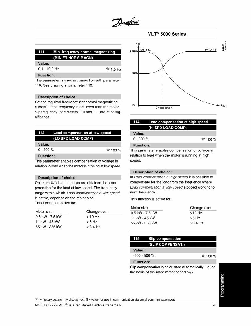
111 Min. frequency normal magnetizing
(MIN FR NORM MAGN)
Value:0.1 - 10.0 Hz 1.0 Hz
Function:This parameter is used in connection with parameter110. See drawing in parameter 110.
Description of choice:Set the required frequency (for normal magnetizingcurrent). If the frequency is set lower than the motorslip frequency, parameters 110 and 111 are of no sig-nificance.
113 Load compensation at low speed
(LO SPD LOAD COMP)
Value:0 - 300 % 100 %
Function:This parameter enables compensation of voltage inrelation to load when the motor is running at low speed.
Description of choice:Optimum U/f characteristics are obtained, i.e. com-pensation for the load at low speed. The frequencyrange within which Load compensation at low speedis active, depends on the motor size.This function is active for:
Motor size Change-over0.5 kW - 7.5 kW < 10 Hz11 kW - 45 kW < 5 Hz55 kW - 355 kW < 3-4 Hz
114 Load compensation at high speed
(HI SPD LOAD COMP)
Value:0 - 300 % 100 %
Function:This parameter enables compensation of voltage inrelation to load when the motor is running at highspeed.
Description of choice:In Load compensation at high speed it is possible tocompensate for the load from the frequency whereLoad compensation at low speed stopped working tomax. frequency.
This function is active for:
Motor size Change-over0.5 kW - 7.5 kW >10 Hz11 kW - 45 kW >5 Hz55 kW - 355 kW >3-4 Hz
115 Slip compensation
(SLIP COMPENSAT.)
Value:-500 - 500 % 100 %
Function:Slip compensation is calculated automatically, i.e. onthe basis of the rated motor speed nM,N.
VLT® 5000 Series
= factory setting, () = display text, [] = value for use in communication via serial communication port
MG.51.C5.22 - VLT is a registered Danfoss trademark. 93
Pro
gram
min
g
In parameter 115, slip compensation can be adjustedin detail, which compensates for tolerances in the val-ue of nM,N.This function is not active together with Variable tor-que (parameter 101 - variable torque graphs), Torquecontrol, Speed feedback and Special motor character-istics.
Description of choice:Enter a %-value of the rated motor frequency (param-eter 104).
116 Slip compensation time constant
(SLIP TIME CONST.)
Value:0.05 - 5.00 sec. 0.50 sec.
Function:This parameter determines the slip compensation re-action speed.
Description of choice:A high value results in slow reaction. Conversely, a lowvalue results in quick reaction.If low-frequency resonance problems are encoun-tered, the time set must be longer.
117 Resonance dampening
(RESONANCE DAMP.)
Value:0 - 500 % 100 %
Function:High-frequency resonance problems can be elimina-ted by setting parameters 117 and 118.
Description of choice:For less resonance oscillation, the value of parameter118 must be increased.
118 Resonance dampening time constant
(DAMP.TIME CONST.)
Value:5 - 50 ms 5 ms
Function:High-frequency resonance problems can be elimina-ted by setting parameters 117 and 118.
Description of choice:Choose the time constant that provides the best damp-ening.
119 High starting torque
(HIGH START TORQ.)
Value:0.0 - 0.5 sec. 0.0 sec.
Function:In order to secure a high starting torque, approx. 2 xIVLT,N for max. 0.5 sec. is allowed. However, the currentis limited by the protection limit of the adjustable fre-quency drive (inverter).
Description of choice:Set the necessary time in which a high starting torqueis desired.
120 Start delay (START DELAY)
Value:0.0 - 10.0 sec. 0.0 sec.
Function:This parameter enables a delay of the starting time.The adjustable frequency drive begins with the startfunction selected in parameter 121.
Description of choice:Set the desired time until acceleration is to begin.
121 Start function (START FUNCTION)
Value:
DC hold in start delay time(DC HOLD/DELAY TIME) [0]
DC brake in start delay time(DC BRAKE/DELAY TIME) [1]
Coasting in start delay time(COAST/DELAY TIME) [2]
Start frequency/voltage clockwise. [3]
VLT® 5000 Series
= factory setting, () = display text, [] = value for use in communication via serial communication port
94 MG.51.C5.22 - VLT is a registered Danfoss trademark.
(CLOCKWISE OPERATION)
Start frequency/voltage in reference direction(HORIZONTAL OPERATION) [4]
VVCplus clockwise(VVC+ CLOCKWISE) [5]
Function:This is where the desired state during start delay (pa-rameter 120) is selected.
Description of choice:Select DC hold in the start delay time [0] so as to ener-gize the motor with a DC holding current (parameter124) in the start delay time.
Select DC brake in the start delay time [1] so as to en-ergize the motor with a DC braking current (parameter125) in the start delay time.Select Coasting in the start delay time [2] and the motorwill not be controlled by the adjustable frequency driveduring the start delay time (inverter off).
Start frequency/voltage clockwise [3] and VVCplus clock-wise [5] is typically used in hoisting applications. Startfrequency/voltage in reference direction [4] is used es-pecially in applications with counterweight.
Select Start frequency/voltage clockwise [3] so as tohave the function described in parameter 130 and 131in the start delay time.The output frequency will equal the setting of the startfrequency in parameter 130, and the output voltage willequal the setting of the start voltage in parameter 131.Regardless of the value assumed by the referencesignal, the output frequency will equal the setting of thestart frequency in parameter 130 and the output volt-age will correspond to the setting of the start voltagein parameter 131.This functionality is used typically in hoisting applica-tions.This is used especially in applications with a cone ar-mature motor, where the start is to be clockwise, fol-lowed by rotation in the reference direction.
Select Start frequency/voltage in reference direction [4]in order to obtain the function described in parameters130 and 131 during the start delay time. The motor willalways rotate in the reference direction.If the reference signal equals zero (0) parameter 130Start frequency will be ignored and the output frequen-cy will equal zero (0). The output voltage will corre-
spond to the setting of the start voltage in parameter131 Start voltage.
Select VVCplus clockwise [5] so as to have only thefunction described in parameter 130 Start frequencyin the start delay time. The start voltage will be calcu-lated automatic. Notice that this function only uses thestart frequency in the start delay time.Regardless of the value assumed by the referencesignal, the output frequency will equal the setting of thestart frequency in parameter 130.
122 Function at stop
(FUNCTION AT STOP)
Value:
Coasting (COAST) [0]
DC hold (DC-HOLD) [1]
Motor check (MOTOR CHECK) [2]
Pre-magnetizing (PREMAGNETIZING) [3]
Function:Here it is possible to select the function of the adjust-able frequency drive after a stop command or whenthe frequency has been ramped down to 0 Hz. Seeparameter 123 with respect to activation of this pa-rameter regardless of whether the stop command isactive.
Description of choice:Select Coasting [0] if the adjustable frequency drive isto 'let go' of the motor (inverter closed).Select DC hold [1] when a DC holding current set inparameter 124 is to be activated.Select Motor check [2] if the adjustable frequencydrive is to check whether or not a motor has been con-nected.Select Pre-magnetizing [3]. The magnetic field is builtup in the motor while it remains stopped. This ensuresthat the motor can produce torque as quickly as pos-sible on starting.
123Min. frequency for activating functionat stop
(MIN.F. FUNC.STOP)
Value:0.0 - 10.0 Hz 0.0 Hz
VLT® 5000 Series
= factory setting, () = display text, [] = value for use in communication via serial communication port
MG.51.C5.22 - VLT is a registered Danfoss trademark. 95
Pro
gram
min
g
Function:This parameter sets the frequency at which the func-tion selected in parameter 122 is to be activated.
Description of choice:Enter the desired frequency.
NOTEIf parameter 123 is set higher than param-eter 130, the start delay function (param-eters 120 and 121) will be skipped.
NOTEIf parameter 123 is set too high, and DChold has been chosen in parameter 122,the output frequency will jump to the valuein parameter 123 without ramping up. Thismay cause an overcurrent warning/alarm.
124 DC holding current
(DC-HOLD CURRENT)
Value:
(OFF)IVLT, NIM, N
× 100 % 50 %
Function:This parameter is used to uphold the motor function(holding torque) or to pre-heat the motor.
NOTEThe maximum value depends on the ratedmotor current. If the DC holding current isactive, the adjustable frequency drive hasa switching frequency of 4 kHz.
Description of choice:This parameter can only be used if DC hold [1] hasbeen selected in parameter 121 or 122. Set it as apercentage value in relation to the rated motor currentIM,N set in parameter 105.100% DC holding current corresponds to IM,N.
Warning: 100% supply for too long maydamage the motor.
VLT 5122-5552, 380-500 V and VLT 5042-5602,525-690 V work with a reduced DC current rated as80% of IVLT,N at 110% overload.
125 DC braking current
(DC BRAKE CURRENT)
Value:
0 (OFF)IVLT, NIM, N
× 100 % 50 %
Function:This parameter is used for setting the DC brake currentthat is activated upon a stop when the DC brake fre-quency set in parameter 127 has been reached, or ifthe DC brake inverse is active via digital terminal 27 orvia a serial communication port. The DC braking cur-rent will be active for the duration of the DC brakingtime set in parameter 126.
NOTEThe maximum value depends on the ratedmotor current. If the DC braking current isactive, the adjustable frequency drive hasa switching frequency of 4.5 kHz.
Description of choice:To be set as a percentage value of the rated motorcurrent IM,N set in parameter 105.100% DC braking current corresponds to IM,N.
Warning: 100% supply for too long maydamage the motor.
VLT 5122-5552, 380-500 V and VLT 5042-5602,525-690 V work with a reduced DC current rated as80% of IVLT,N at 110% overload.
126 DC braking time
(DC BRAKING TIME)
Value:0.0 (OFF) - 60.0 sec. 10.0 sec.
VLT® 5000 Series
= factory setting, () = display text, [] = value for use in communication via serial communication port
96 MG.51.C5.22 - VLT is a registered Danfoss trademark.
Function:This parameter is for setting the DC braking time forwhich the DC braking current (parameter 125) is to beactive.
Description of choice:Set the desired time.
127 DC brake cut-in frequency
(DC BRAKE CUT-IN)
Value:0.0 - parameter 202 0.0 Hz (OFF)
Function:This parameter is for setting the DC brake cut-in fre-quency at which the DC braking current (parameter125) is to be active, in connection with a stop com-mand.
Description of choice:Set the desired frequency.
128 Motor thermal protection
(MOT.THERM PROTEC)
Value:
No protection (NO PROTECTION) [0]
Thermistor warning (THERMISTOR WARN) [1]
Thermistor trip (THERMISTOR TRIP) [2]
ETR Warning 1 (ETR WARNING1) [3]
ETR Trip 1 (ETR TRIP1) [4]
ETR Warning 2 (ETR WARNING2) [5]
ETR Trip 2 (ETR TRIP2) [6]
ETR Warning 3 (ETR WARNING3) [7]
ETR Trip 3 (ETR TRIP3) [8]
ETR Warning 4 (ETR WARNING 4) [9]
ETR Trip 4 (ETR TRIP4) [10]
Function:The adjustable frequency drive is able to monitor themotor temperature in two different ways:
- Via a thermistor sensor connected to one ofthe analog inputs, terminals 53 and 54 (pa-rameters 308 and 311).
- Calculation of the thermal load, based on thecurrent load and the time. This is comparedwith the rated motor current IM,N and the ratedmotor frequency fM,N. The calculations madetake into account the need for a lower load atlower speeds because of less cooling fromthe fan.
ETR functions 1-4 do not start calculating the load untilthere is a switch-over to the Setup in which they wereselected. This enables the use of the ETR function,even where two or several motors alternate. For theNorth American market: The ETR functions provideclass 10 or 20 motor overload protection in accordancewith NEC.
Description of choice:Select No protection if no warning or tripping is re-quired when the motor is overloaded.Select Thermistor warning if a warning is desired whenthe connected thermistor - and thus the motor- gets too hot.Select Thermistor trip if cutting out (trip) is desiredwhen the connected thermistor - and thus the motor- overheats.
Select ETR Warning 1-4, if a warning is to come up onthe display when the motor is overloaded according tothe calculations.Select ETR Trip 1-4 if tripping is desired when the motoris overloaded according to the calculations.The adjustable frequency drive can also be program-med to give off a warning signal via one of the digitaloutputs, in which case the signal is given both forwarning and for trip (thermal warning).
VLT® 5000 Series
= factory setting, () = display text, [] = value for use in communication via serial communication port
MG.51.C5.22 - VLT is a registered Danfoss trademark. 97
Pro
gram
min
g
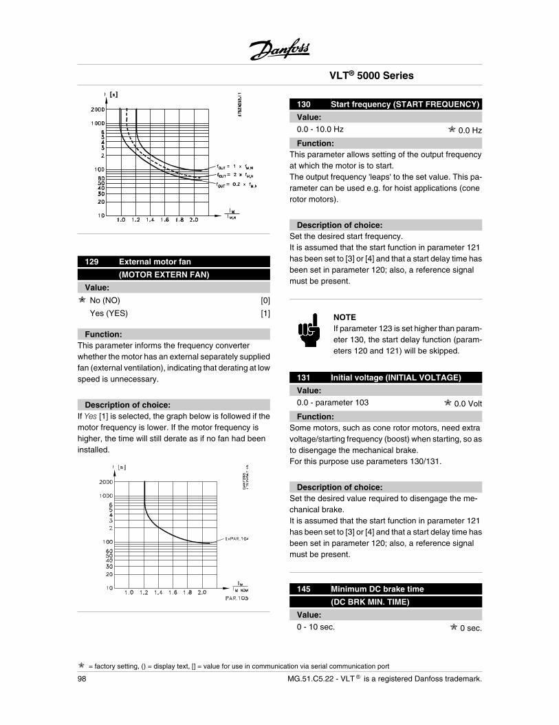
129 External motor fan
(MOTOR EXTERN FAN)
Value:
No (NO) [0]
Yes (YES) [1]
Function:This parameter informs the frequency converterwhether the motor has an external separately suppliedfan (external ventilation), indicating that derating at lowspeed is unnecessary.
Description of choice:If Yes [1] is selected, the graph below is followed if themotor frequency is lower. If the motor frequency ishigher, the time will still derate as if no fan had beeninstalled.
130 Start frequency (START FREQUENCY)
Value:0.0 - 10.0 Hz 0.0 Hz
Function:This parameter allows setting of the output frequencyat which the motor is to start.The output frequency 'leaps' to the set value. This pa-rameter can be used e.g. for hoist applications (conerotor motors).
Description of choice:Set the desired start frequency.It is assumed that the start function in parameter 121has been set to [3] or [4] and that a start delay time hasbeen set in parameter 120; also, a reference signalmust be present.
NOTEIf parameter 123 is set higher than param-eter 130, the start delay function (param-eters 120 and 121) will be skipped.
131 Initial voltage (INITIAL VOLTAGE)
Value:0.0 - parameter 103 0.0 Volt
Function:Some motors, such as cone rotor motors, need extravoltage/starting frequency (boost) when starting, so asto disengage the mechanical brake.For this purpose use parameters 130/131.
Description of choice:Set the desired value required to disengage the me-chanical brake.It is assumed that the start function in parameter 121has been set to [3] or [4] and that a start delay time hasbeen set in parameter 120; also, a reference signalmust be present.
145 Minimum DC brake time
(DC BRK MIN. TIME)
Value:0 - 10 sec. 0 sec.
VLT® 5000 Series
= factory setting, () = display text, [] = value for use in communication via serial communication port
98 MG.51.C5.22 - VLT is a registered Danfoss trademark.
Function:If a minimum DC brake time is necessary before a newstart is possible, this parameter can be set.
Description of choice:Select the desired time.
VLT® 5000 Series
MG.51.C5.22 - VLT is a registered Danfoss trademark. 99
Pro
gram
min
g
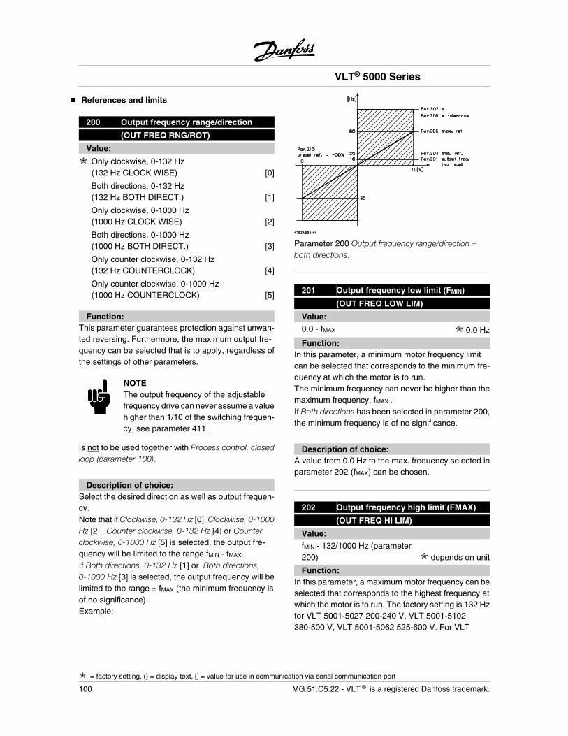
References and limits
200 Output frequency range/direction
(OUT FREQ RNG/ROT)
Value:
Only clockwise, 0-132 Hz(132 Hz CLOCK WISE) [0]
Both directions, 0-132 Hz(132 Hz BOTH DIRECT.) [1]
Only clockwise, 0-1000 Hz(1000 Hz CLOCK WISE) [2]
Both directions, 0-1000 Hz(1000 Hz BOTH DIRECT.) [3]
Only counter clockwise, 0-132 Hz(132 Hz COUNTERCLOCK) [4]
Only counter clockwise, 0-1000 Hz(1000 Hz COUNTERCLOCK) [5]
Function:This parameter guarantees protection against unwan-ted reversing. Furthermore, the maximum output fre-quency can be selected that is to apply, regardless ofthe settings of other parameters.
NOTEThe output frequency of the adjustablefrequency drive can never assume a valuehigher than 1/10 of the switching frequen-cy, see parameter 411.
Is not to be used together with Process control, closedloop (parameter 100).
Description of choice:Select the desired direction as well as output frequen-cy.Note that if Clockwise, 0-132 Hz [0], Clockwise, 0-1000Hz [2], Counter clockwise, 0-132 Hz [4] or Counterclockwise, 0-1000 Hz [5] is selected, the output fre-quency will be limited to the range fMIN - fMAX.If Both directions, 0-132 Hz [1] or Both directions,0-1000 Hz [3] is selected, the output frequency will belimited to the range ± fMAX (the minimum frequency isof no significance).Example:
Parameter 200 Output frequency range/direction =both directions.
201 Output frequency low limit (FMIN)
(OUT FREQ LOW LIM)
Value:0.0 - fMAX 0.0 Hz
Function:In this parameter, a minimum motor frequency limitcan be selected that corresponds to the minimum fre-quency at which the motor is to run.The minimum frequency can never be higher than themaximum frequency, fMAX .If Both directions has been selected in parameter 200,the minimum frequency is of no significance.
Description of choice:A value from 0.0 Hz to the max. frequency selected inparameter 202 (fMAX) can be chosen.
202 Output frequency high limit (FMAX)
(OUT FREQ HI LIM)
Value:fMIN - 132/1000 Hz (parameter200) depends on unit
Function:In this parameter, a maximum motor frequency can beselected that corresponds to the highest frequency atwhich the motor is to run. The factory setting is 132 Hzfor VLT 5001-5027 200-240 V, VLT 5001-5102380-500 V, VLT 5001-5062 525-600 V. For VLT
VLT® 5000 Series
= factory setting, () = display text, [] = value for use in communication via serial communication port
100 MG.51.C5.22 - VLT is a registered Danfoss trademark.
5032-5052 200-240 V, VLT 5122-5552 380-500 V and5042-5602 525-690 V the factory setting is 66 Hz.
See also parameter 205.
NOTEThe output frequency of the adjustablefrequency drive can never assume a valuehigher than 1/10 of the switching frequen-cy.
Description of choice:A value from fMIN to the choice made in parameter 200can be selected.
NOTEIf the maximum motor frequency is set atmore than 500 Hz, parameter 446 must beset at 60° AVM [0] switching pattern.
203 Reference/feedback area
(REF/FEEDB. RANGE)
Value:
Min - Max (MIN - MAX) [0]
- Max - + Max (-MAX-+MAX) [1]
Function:This parameter decides whether the reference signaland the feedback signal are to be positive or can beboth positive and negative.The minimum limit may be a negative value, unlessSpeed control, closed loop has been selected(parameter 100).Choose Min - Max [0] if Process control, closed loophas been selected in parameter 100.
Description of choice:Choose the desired range.
204 Minimum reference
(MIN. REFERENCE)
Value:-100,000.000 - RefMAX 0.000
Depends on parameter 100.
Function:The Minimum reference gives the minimum value thatcan be assumed by the sum of all references. Minimumreference is only active if Min - Max [0] has been setin parameter 203; however, it is always active in Proc-ess control, closed loop (parameter 100).
Description of choice:Is only active when parameter 203 has been set to Min- Max [0].Set the desired value.The unit follows the choice of configuration in param-eter 100.
Speed control, open loop: HzSpeed control, closed loop: rpmTorque control, open loop: NmTorque control, speed feedback: NmProcess control, closed loop: Process units (par. 416)
Special motor characteristics, activated in parameter101, use the unit selected in parameter 100.
205 Maximum reference
(MAX. REFERENCE)
Value:RefMIN - 100,000.000 50.000
Function:The Maximum reference gives the highest value thatcan be assumed by the sum of all references. If closedloop has been selected in parameter 100, the maxi-mum reference cannot be set higher than the maxi-mum feedback (parameter 415).
Description of choice:Set the desired value.The unit follows the choice of configuration in param-eter 100.
Speed control, open loop: HzSpeed control, closed loop: rpmTorque control, open loop: NmTorque control, speed feedback: NmProcess control, closed loop: Process units (par. 416)
Special motor characteristics, activated in parameter101, use the unit selected in parameter 100.
VLT® 5000 Series
= factory setting, () = display text, [] = value for use in communication via serial communication port
MG.51.C5.22 - VLT is a registered Danfoss trademark. 101
Pro
gram
min
g

206 Ramp type (RAMP TYPE)
Value:
Linear (LINEAR) [0]
Sinusoidal (S1) [1]
Sin2 (S2) [2]
Sin3 (S3) [3]
Sin 2 filter (S2 FILTER) [4]
Function:There is a choice of 4 different ramp types.
Description of choice:Select the desired ramp type, depending on require-ments concerning acceleration/deceleration.The ramp is recalculated if the reference is changedduring ramping, resulting in an increase of the rampingtime.Selection S2 filter [4] is not recalculated if the referenceis changed during ramping.
207 Ramp-up time 1
(RAMP UP TIME 1)
Value:0.05 - 3600 sec. depends on unit
Function:The ramp-up time is the acceleration time from 0 Hz tothe rated motor frequency fM,N (parameter 104) or therated motor speed nM,N (if Speed control, closed loophas been selected in parameter 100). This presuppo-
ses that the output current does not reach the torquelimit (to be set in parameter 221).
Description of choice:Program the desired ramp-up time.
208 Ramp-down time 1
(RAMP DOWN TIME 1)
Value:0.05 - 3600 sec. depends on unit
Function:The ramp-down time is the deceleration timefrom therated motor frequency f M,N (parameter 104) to 0 Hz orfrom the rated motor speed nM,N , provided there is noover-voltage in the inverter because of regenerativeoperation of the motor, or if the generated current rea-ches the torque limit (to be set in parameter 222).
Description of choice:Program the desired ramp-down time.
209 Ramp-up time 2
(RAMP UP TIME 2)
Value:0.05 - 3600 sec. depends on unit
Function:See description of parameter 207.
Description of choice:Program the desired ramp-up time.Switching from ramp 1 to ramp 2 is effected via a signalon digital input terminal 16, 17, 29, 32 or 33.
VLT® 5000 Series
= factory setting, () = display text, [] = value for use in communication via serial communication port
102 MG.51.C5.22 - VLT is a registered Danfoss trademark.
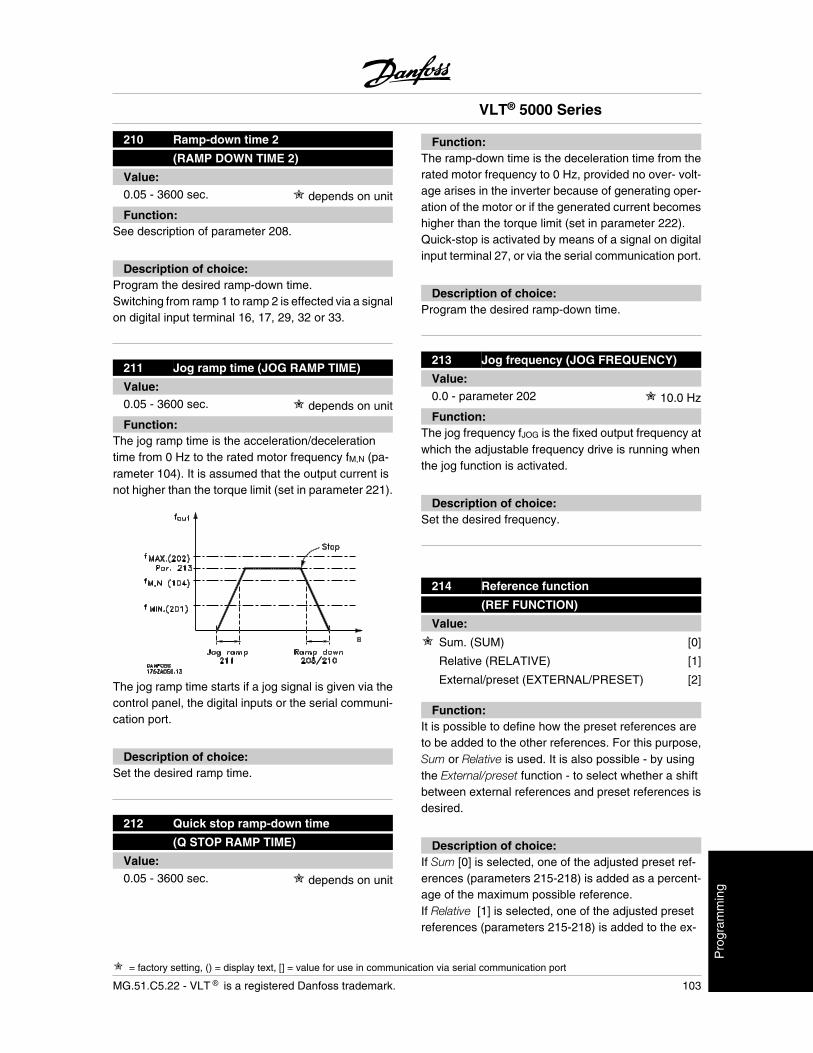
210 Ramp-down time 2
(RAMP DOWN TIME 2)
Value:0.05 - 3600 sec. depends on unit
Function:See description of parameter 208.
Description of choice:Program the desired ramp-down time.Switching from ramp 1 to ramp 2 is effected via a signalon digital input terminal 16, 17, 29, 32 or 33.
211 Jog ramp time (JOG RAMP TIME)
Value:0.05 - 3600 sec. depends on unit
Function:The jog ramp time is the acceleration/decelerationtime from 0 Hz to the rated motor frequency fM,N (pa-rameter 104). It is assumed that the output current isnot higher than the torque limit (set in parameter 221).
The jog ramp time starts if a jog signal is given via thecontrol panel, the digital inputs or the serial communi-cation port.
Description of choice:Set the desired ramp time.
212 Quick stop ramp-down time
(Q STOP RAMP TIME)
Value:0.05 - 3600 sec. depends on unit
Function:The ramp-down time is the deceleration time from therated motor frequency to 0 Hz, provided no over- volt-age arises in the inverter because of generating oper-ation of the motor or if the generated current becomeshigher than the torque limit (set in parameter 222).Quick-stop is activated by means of a signal on digitalinput terminal 27, or via the serial communication port.
Description of choice:Program the desired ramp-down time.
213 Jog frequency (JOG FREQUENCY)
Value:0.0 - parameter 202 10.0 Hz
Function:The jog frequency fJOG is the fixed output frequency atwhich the adjustable frequency drive is running whenthe jog function is activated.
Description of choice:Set the desired frequency.
214 Reference function
(REF FUNCTION)
Value:
Sum. (SUM) [0]
Relative (RELATIVE) [1]
External/preset (EXTERNAL/PRESET) [2]
Function:It is possible to define how the preset references areto be added to the other references. For this purpose,Sum or Relative is used. It is also possible - by usingthe External/preset function - to select whether a shiftbetween external references and preset references isdesired.
Description of choice:If Sum [0] is selected, one of the adjusted preset ref-erences (parameters 215-218) is added as a percent-age of the maximum possible reference.If Relative [1] is selected, one of the adjusted presetreferences (parameters 215-218) is added to the ex-
VLT® 5000 Series
= factory setting, () = display text, [] = value for use in communication via serial communication port
MG.51.C5.22 - VLT is a registered Danfoss trademark. 103
Pro
gram
min
g
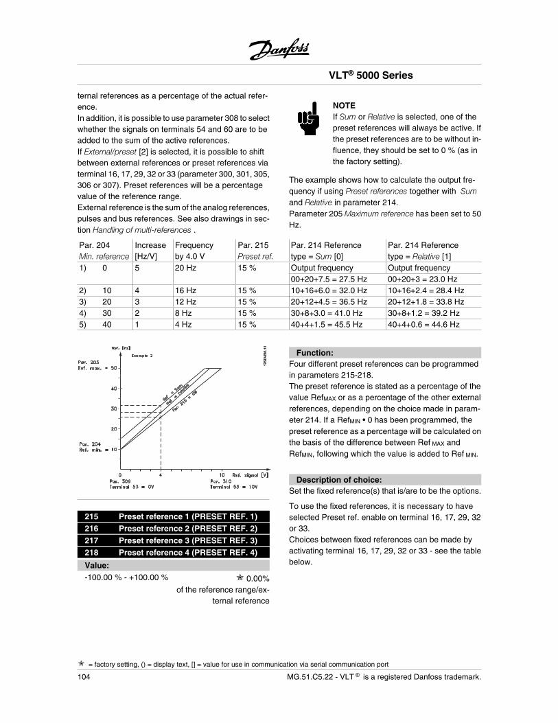
ternal references as a percentage of the actual refer-ence.In addition, it is possible to use parameter 308 to selectwhether the signals on terminals 54 and 60 are to beadded to the sum of the active references.If External/preset [2] is selected, it is possible to shiftbetween external references or preset references viaterminal 16, 17, 29, 32 or 33 (parameter 300, 301, 305,306 or 307). Preset references will be a percentagevalue of the reference range.External reference is the sum of the analog references,pulses and bus references. See also drawings in sec-tion Handling of multi-references .
NOTEIf Sum or Relative is selected, one of thepreset references will always be active. Ifthe preset references are to be without in-fluence, they should be set to 0 % (as inthe factory setting).
The example shows how to calculate the output fre-quency if using Preset references together with Sumand Relative in parameter 214.Parameter 205 Maximum reference has been set to 50Hz.
Par. 204Min. reference
Increase[Hz/V]
Frequencyby 4.0 V
Par. 215Preset ref.
Par. 214 Referencetype = Sum [0]
Par. 214 Referencetype = Relative [1]
1) 0 5 20 Hz 15 % Output frequency Output frequency00+20+7.5 = 27.5 Hz 00+20+3 = 23.0 Hz
2) 10 4 16 Hz 15 % 10+16+6.0 = 32.0 Hz 10+16+2.4 = 28.4 Hz3) 20 3 12 Hz 15 % 20+12+4.5 = 36.5 Hz 20+12+1.8 = 33.8 Hz4) 30 2 8 Hz 15 % 30+8+3.0 = 41.0 Hz 30+8+1.2 = 39.2 Hz5) 40 1 4 Hz 15 % 40+4+1.5 = 45.5 Hz 40+4+0.6 = 44.6 Hz
215 Preset reference 1 (PRESET REF. 1)216 Preset reference 2 (PRESET REF. 2)217 Preset reference 3 (PRESET REF. 3)218 Preset reference 4 (PRESET REF. 4)
Value:-100.00 % - +100.00 % 0.00%
of the reference range/ex-ternal reference
Function:Four different preset references can be programmedin parameters 215-218.The preset reference is stated as a percentage of thevalue RefMAX or as a percentage of the other externalreferences, depending on the choice made in param-eter 214. If a RefMIN • 0 has been programmed, thepreset reference as a percentage will be calculated onthe basis of the difference between Ref MAX andRefMIN, following which the value is added to Ref MIN.
Description of choice:Set the fixed reference(s) that is/are to be the options.
To use the fixed references, it is necessary to haveselected Preset ref. enable on terminal 16, 17, 29, 32or 33.Choices between fixed references can be made byactivating terminal 16, 17, 29, 32 or 33 - see the tablebelow.
VLT® 5000 Series
= factory setting, () = display text, [] = value for use in communication via serial communication port
104 MG.51.C5.22 - VLT is a registered Danfoss trademark.
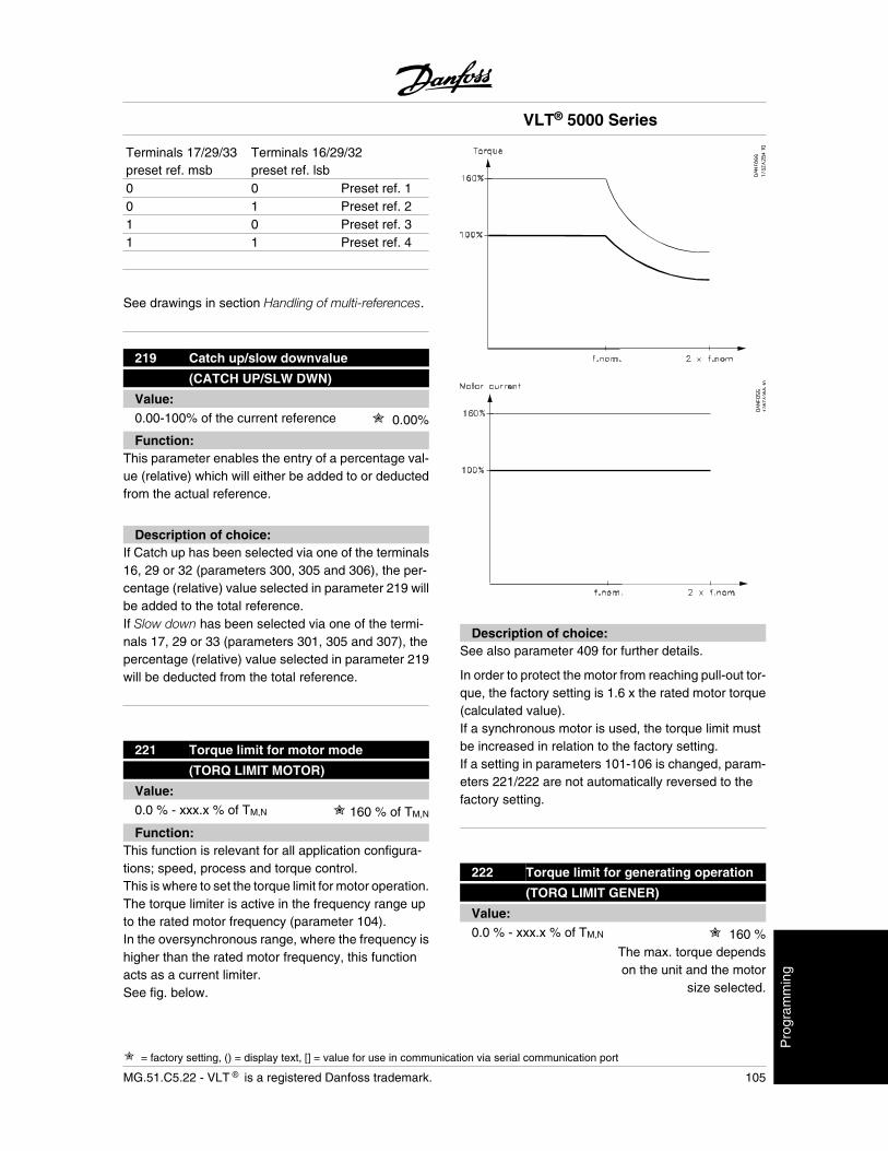
Terminals 17/29/33preset ref. msb
Terminals 16/29/32preset ref. lsb
0 0 Preset ref. 10 1 Preset ref. 21 0 Preset ref. 31 1 Preset ref. 4
See drawings in section Handling of multi-references.
219 Catch up/slow downvalue
(CATCH UP/SLW DWN)
Value:0.00-100% of the current reference 0.00%
Function:This parameter enables the entry of a percentage val-ue (relative) which will either be added to or deductedfrom the actual reference.
Description of choice:If Catch up has been selected via one of the terminals16, 29 or 32 (parameters 300, 305 and 306), the per-centage (relative) value selected in parameter 219 willbe added to the total reference.If Slow down has been selected via one of the termi-nals 17, 29 or 33 (parameters 301, 305 and 307), thepercentage (relative) value selected in parameter 219will be deducted from the total reference.
221 Torque limit for motor mode
(TORQ LIMIT MOTOR)
Value:0.0 % - xxx.x % of TM,N 160 % of TM,N
Function:This function is relevant for all application configura-tions; speed, process and torque control.This is where to set the torque limit for motor operation.The torque limiter is active in the frequency range upto the rated motor frequency (parameter 104).In the oversynchronous range, where the frequency ishigher than the rated motor frequency, this functionacts as a current limiter.See fig. below.
Description of choice:See also parameter 409 for further details.
In order to protect the motor from reaching pull-out tor-que, the factory setting is 1.6 x the rated motor torque(calculated value).If a synchronous motor is used, the torque limit mustbe increased in relation to the factory setting.If a setting in parameters 101-106 is changed, param-eters 221/222 are not automatically reversed to thefactory setting.
222 Torque limit for generating operation
(TORQ LIMIT GENER)
Value:0.0 % - xxx.x % of TM,N 160 %
The max. torque dependson the unit and the motor
size selected.
VLT® 5000 Series
= factory setting, () = display text, [] = value for use in communication via serial communication port
MG.51.C5.22 - VLT is a registered Danfoss trademark. 105
Pro
gram
min
g
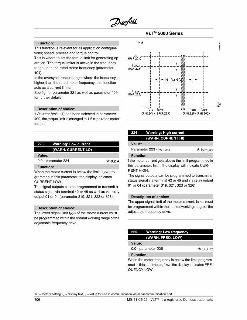
Function:This function is relevant for all application configura-tions; speed, process and torque control.This is where to set the torque limit for generating op-eration. The torque limiter is active in the frequencyrange up to the rated motor frequency (parameter104).In the oversynchronous range, where the frequency ishigher than the rated motor frequency, this functionacts as a current limiter.See fig. for parameter 221 as well as parameter 409for further details.
Description of choice:If Resistor brake [1] has been selected in parameter400, the torque limit is changed to 1.6 x the rated motortorque.
223 Warning: Low current
(WARN. CURRENT LO)
Value:0.0 - parameter 224 0.2 A
Function:When the motor current is below the limit, ILOW pro-grammed in this parameter, the display indicatesCURRENT LOW.The signal outputs can be programmed to transmit astatus signal via terminal 42 or 45 as well as via relayoutput 01 or 04 (parameter 319, 321, 323 or 326).
Description of choice:The lower signal limit ILOW of the motor current mustbe programmed within the normal working range of theadjustable frequency drive.
224 Warning: High current
(WARN. CURRENT HI)
Value:Parameter 223 - IVLT,MAX IVLT,MAX
Function:f the motor current gets above the limit programmed inthis parameter, IHIGH, the display will indicate CUR-RENT HIGH.The signal outputs can be programmed to transmit astatus signal via terminal 42 or 45 and via relay output01 or 04 (parameter 319, 321, 323 or 326).
Description of choice:The upper signal limit of the motor current, IHIGH, mustbe programmed within the normal working range of theadjustable frequency drive.
225 Warning: Low frequency
(WARN. FREQ. LOW)
Value:0.0 - parameter 226 0.0 Hz
Function:When the motor frequency is below the limit program-med in this parameter, fLOW, the display indicates FRE-QUENCY LOW.
VLT® 5000 Series
= factory setting, () = display text, [] = value for use in communication via serial communication port
106 MG.51.C5.22 - VLT is a registered Danfoss trademark.
The signal outputs can be programmed to transmit astatus signal via terminal 42 or 45 and via relay output01 or 04 (parameter 319, 321, 323 or 326).
Description of choice:The lower signal limit of the motor frequency, fLOW, isto be programmed within the normal working range ofthe adjustable frequency drive.See drawing at parameter 223.
226 Warning: High frequency
(WARN. FREQ. HIGH)
Value:parameter 225 - parameter 202 132.0 Hz
Function:When the motor frequency is above the limit program-med in this parameter, fHIGH, the display will indicateFREQUENCY HIGH.The signal outputs can be programmed to transmit astatus signal via terminal 42 or 45 and via relay output01 or 04 (parameter 319, 321, 323 or 326).
Description of choice:The upper signal limit of the motor frequency, fHIGH,must be programmed within the normal working rangeof the adjustable frequency drive.See drawing at parameter 223.
227 Warning: Low feedback
(WARN. FEEDB. LOW)
Value:-100,000.000 - parameter 228. -4000.000
Function:If the connected feedback signal gets below the valueset in this parameter, the signal outputs can be pro-grammed to transmit a status signal via terminal 42 or45 and via relay output 01 or 04 (parameter 319, 321,323 or 326).
Description of choice:Set the desired value.
228 Warning: High feedback
(WARN. FEEDB HIGH)
Value:parameter 227 - 100,000.000 4000.000
Function:If the connected feedback signal gets above the valueset in this parameter, the signal outputs can be pro-grammed to transmit a status signal via terminal 42 or45 and via relay output 01 or 04 (parameter 319, 321,323 or 326).
Description of choice:Set the desired value.
229 Frequency bypass, bandwidth
(FREQ BYPASS B.W.)
Value:0 (OFF) - 100% 0 (OFF) %
Function:Some systems call for some output frequencies to beavoided because of resonance problems in the sys-tem.In parameters 230-233 these output frequencies canbe programmed for bypassing (Frequency bypass). Inthis parameter (229), a bandwidth can be defined oneither side of these frequency bypasses.The frequency bypass function is not active if par. 002is set to Local and par. 013 is set to LCP ctrl/Openloop or LCP+dig ctrl/Open loop.
Description of choice:The bypass bandwidth is set as a percentage of thebypass frequency which is selected in parameter230-233.The bypass bandwidth indicates max. variation of thebypass frequency.
Example: A bypass frequency of 100 Hz and a bypassbandwidth of 1% are selected. In this case the bypassfrequency can vary between 99.5 Hz and 100.5 Hz i.e.1% of 100 Hz.
VLT® 5000 Series
= factory setting, () = display text, [] = value for use in communication via serial communication port
MG.51.C5.22 - VLT is a registered Danfoss trademark. 107
Pro
gram
min
g
230 Frequency bypass 1 (FREQ. BYPASS 1)231 Frequency bypass 2 (FREQ. BYPASS 2)232 Frequency bypass 3 (FREQ. BYPASS 3)233 Frequency bypass 4 (FREQ. BYPASS 4)
Value:0.0 - parameter 200 0.0 Hz
Function:Some systems call for some output frequencies to beavoided because of resonance problems in the sys-tem.
Description of choice:Enter the frequencies to be avoided.See also parameter 229.
234 Motor phase monitor
(MOTOR PHASE MON)
Value:
Enable (ENABLE) [0]
Disable (DISABLE) [1]
Function:In this parameter it is possible to select monitoring ofthe motor phases.
Description of choice:If Enable is selected, the adjustable frequency drive willreact on a missing motor phase which will result inalarm 30, 31 or 32.If Disable is selected, no alarm is given if a motor phaseis missing. The motor can be damaged/overheated ifit runs on only two phases. It is therefore recommen-ded to keep the missing motor phase function ENA-BLED.
VLT® 5000 Series
108 MG.51.C5.22 - VLT is a registered Danfoss trademark.
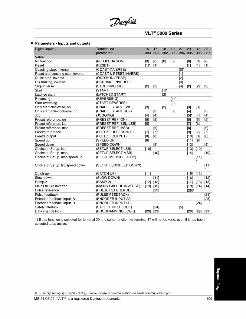
Parameters - Inputs and outputs
Digital inputs Terminal no. 16 17 18 19 27 29 32 33parameter 300 301 302 303 304 305 306 307
Value:No function (NO OPERATION) [0] [0] [0] [0] [0] [0] [0]Reset (RESET) [1]* [1] [1] [1] [1]Coasting stop, inverse (COAST INVERSE) [0]*Reset and coasting stop, inverse (COAST & RESET INVERS) [1]Quick-stop, inverse (QSTOP INVERSE) [2]DC-braking, inverse (DCBRAKE INVERSE) [3]Stop inverse (STOP INVERSE) [2] [2] [4] [2] [2] [2]Start (START) [1]*Latched start (LATCHED START) [2]Reversing (REVERSING) [1]*Start reversing (START REVERSE) [2]Only start clockwise, on (ENABLE START FWD.) [3] [3] [3] [3]Only start anti-clockwise, on (ENABLE START REV) [3] [3] [4] [3]Jog (JOGGING) [4] [4] [5]* [4] [4]Preset reference, on (PRESET REF. ON) [5] [5] [5] [5] [5]Preset reference, lsb (PRESET REF. SEL. LSB) [5] [7] [6]Preset reference, msb (PRESET REF. MSB) [6] [8] [6]Freeze reference (FREEZE REFERENCE) [7] [7]* [9] [7] [7]Freeze output (FREEZE OUTPUT) [8] [8] [10] [8] [8]Speed up (SPEED UP) [9] [11] [9]Speed down (SPEED DOWN) [9] [12] [9]Choice of Setup, lsb (SETUP SELECT LSB) [10] [13] [10]Choice of Setup, msb (SETUP SELECT MSB) [10] [14] [10]Choice of Setup, msb/speed up (SETUP MSB/SPEED UP) [11]
*Choice of Setup, lsb/speed down (SETUP LSB/SPEED DOWN) [11]
*Catch-up (CATCH UP) [11] [15] [12]Slow-down (SLOW DOWN) [11] [16] [12]Ramp 2 (RAMP 2) [12] [12] [17] [13] [13]Mains failure inverted (MAINS FAILURE INVERSE) [13] [13] [18] [14] [14]Pulse reference (PULSE REFERENCE) [23] [28]1
Pulse feedback (PULSE FEEDBACK) [24]Encoder feedback input, A (ENCODER INPUT 2A) [25]Encoder feedback input, B (ENCODER INPUT 2B) [24]Safety interlock (SAFETY INTERLOCK) [24] [5]Data change lock (PROGRAMMING LOCK) [29] [29] [29] [29] [29] 1) If this function is selected for terminal 29, the same function for terminal 17 will not be valid, even if it has beenselected to be active.
VLT® 5000 Series
= factory setting, () = display text, [] = value for use in communication via serial communication port
MG.51.C5.22 - VLT is a registered Danfoss trademark. 109
Pro
gram
min
g
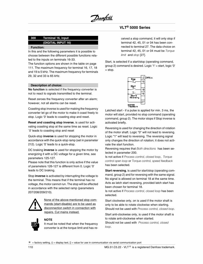
300 Terminal 16, input
(DIGITAL INPUT 16)
Function:In this and the following parameters it is possible tochoose between the different possible functions rela-ted to the inputs on terminals 16-33.The function options are shown in the table on page111. The maximum frequency for terminal 16, 17, 18and 19 is 5 kHz. The maximum frequency for terminals29, 32 and 33 is 65 kHz.
Description of choice:No function is selected if the frequency converter isnot to react to signals transmitted to the terminal.
Reset zeroes the frequency converter after an alarm;however, not all alarms can be reset.
Coasting stop inverse is used for making the frequencyconverter let go of the motor to make it coast freely tostop. Logic '0' leads to coasting stop and reset.
Reset and coasting stop inverse, is used for acti-vating coasting stop at the same time as reset. Logic`0' leads to coasting stop and reset
Quick-stop inverse is used for stopping the motor inaccordance with the quick-stop ramp (set in parameter212). Logic '0' leads to a quick-stop.
DC braking inverse is used for stopping the motor byenergizing it with a DC voltage for a given time, seeparameters 125-127.Please note that this function is only active if the valueof parameters 126-127 is different from 0. Logic '0'leads to DC braking.
Stop inverse is activated by interrupting the voltage tothe terminal. This means that if the terminal has novoltage, the motor cannot run. The stop will be effectedin accordance with the selected ramp (parameters207/208/209/210).
None of the above-mentioned stop com-mands (start-disable) are to be used asdisconnection switch in connection withrepairs. Cut mains instead.
NOTEIt must be noted that when the frequencyconverter is at the torque limit and has re-
ceived a stop command, it will only stop ifterminal 42, 45, 01 or 04 has been con-nected to terminal 27. The data choice onterminal 42, 45, 01 or 04 must be Torquelimit and stop [27].
Start, is selected if a start/stop (operating command,group 2) command is desired. Logic '1' = start, logic '0'= stop.
Latched start - if a pulse is applied for min. 3 ms, themotor will start, provided no stop command (operatingcommand, group 2). The motor stops if Stop inverse isactivated briefly.
Reversing is used for changing the direction of rotationof the motor shaft. Logic "0" will not lead to reversing.Logic "1" will lead to reversing. The reversing signalonly changes the direction of rotation; it does not acti-vate the start function.Reversing requires that Both directions has been se-lected in parameter 200.Is not active if Process control, closed loop, Torquecontrol open loop or Torque control, speed feedbackhas been selected.
Start reversing, is used for start/stop (operating com-mand, group 2) and for reversing with the same signal.No signal is allowed on terminal 18 at the same time.Acts as latch start reversing, provided latch start hasbeen chosen for terminal 18.Is not active if Process control, closed loop has beenselected.
Start clockwise only, on is used if the motor shaft isonly to be able to rotate clockwise when starting.Should not be used with Process control, closed loop.
Start anti-clockwise only, is used if the motor shaft isto rotate anti-clockwise when started.Should not be used with Process control, closedloop.
VLT® 5000 Series
= factory setting, () = display text, [] = value for use in communication via serial communication port
110 MG.51.C5.22 - VLT is a registered Danfoss trademark.
Jog is used for overriding the output frequency to thejog frequency set in parameter 213. The ramp time canbe set in parameter 211. Jog is not active if a stopcommand has been given (start-disable). Jog over-rides stop (operating command, group 2).
Preset reference, on is used for shifting between ex-ternal reference and preset reference. It is assumedthat External/preset [2] has been selected in parameter214. Logic '0' = external references active; logic '1' =one of the four preset references is active in accord-ance with the table below.
Preset reference, lsb and Preset reference, msbenables a choice of one of the four preset references,in accordance with the table below.
Preset ref. msb Preset ref. lsbPreset ref. 1 0 0Preset ref. 2 0 1Preset ref. 3 1 0Preset ref. 4 1 1
Freeze reference - freezes the actual reference. Thefrozen reference is now the point of enable/conditionfor Speed up and Speed down to be used.If speed up/down is used, the speed change alwaysfollows ramp 2 (parameters 209/210) in the range 0 -Ref MAX.
Freeze output - freezes the actual motor frequency(Hz). The frozen motor frequency is now the point ofenable/condition for Speed up and Speed down to beused.If speed up/down is used, the speed change alwaysfollows ramp 2 (parameters 209/210) in the range 0 -fM,N.
NOTEIf Freeze output is active, the frequencyconverter cannot be stopped via terminals18 and 19, but only via terminal 27 (to beprogrammed for Coasting stop, inverse [0]or Reset and coasting stop, inverse [1]).
After Freeze output, the PID integrators are reset.
Speed up and Speed down are selected if digital con-trol of the up/down speed is desired (motor potentiom-eter). This function is only active if Freeze reference orFreeze output has been selected. As long as there is alogic `1` on the terminal selected for speed up, the ref-erence or the output frequency will increase. Followramp 2 (parameter 209) in the range 0 - fMIN.
As long as there is a logic `1` on the terminal selectedfor speed down, the reference or the output frequencywill be reduced. Follow ramp 2 (parameter 210) in therange 0 - fMIN.Pulses (logic `1` minimum high for 3 ms and a mini-mum pause of 3 ms) will lead to a change of speed of0.1% (reference) or 0.1 Hz (output frequency).
Example:
Terminal Freeze ref./(16) (17) Freeze output
No speed change 0 0 1Speed down 0 1 1Speed up 1 0 1Speed down 1 1 1
The speed reference frozen via the control panel canbe changed even if the frequency converter has stop-ped. The frozen reference will be remembered in caseof a mains drop-out.
Selection of Setup, lsb and Selection of Setup,msb enables a choice of one of the four Setups; how-ever, this presupposes that parameter 004 has beenset at Multi Setup.
Selection of Setup, msb/Speed up and Selection ofSetup, lsb/Speed down - together with the use ofFreeze reference or Freeze output - enable up/downspeed change.
The selection of Setup occurs in accordance with thebelow verification table:
Selection of Setup Freeze ref/(32)msb (33)lsb Freeze output
Setup 1 0 0 0Setup 2 0 1 0Setup 3 1 0 0Setup 4 1 1 0No speed change 0 0 1Speed down 0 1 1Speed up 1 0 1Speed down 1 1 1
Catch-up/Slow-down is selected if the reference valueis to be increased or reduced by a programmable per-centage value set in parameter 219.
Slow-down Catch-up
Unchanged speed 0 0Reduced by %-value 1 0Increased by %-value 0 1Reduced by %-value 1 1
Ramp 2 is selected if a change between ramp 1 (pa-rameters 207-208) and ramp 2 (209-210) is desired.Logic '0' leads to ramp 1, while logic '1' leads to ramp2.
VLT® 5000 Series
= factory setting, () = display text, [] = value for use in communication via serial communication port
MG.51.C5.22 - VLT is a registered Danfoss trademark. 111
Pro
gram
min
g
Mains failure inverted is to be selected if parameter407 Mains failure and/or parameter 408 Quick dis-charge is to be activated. Mains failure inverted isactive in the logical `0' situation.See also Mains fault/quick discharge on page 66, ifrequired.
NOTEThe frequency converter can be totallydamaged by repeating the Quick dis-charge function on the digital input withmains voltage connected to the SYSTEM.
Pulse reference is selected if a pulse sequence (fre-quency) of 0 Hz is used, corresponding to RefMIN,parameter 204. The frequency is set in parameter 327,corresponding to RefMAX.
Pulse feedback is selected if a pulse sequence (fre-quency) is selected as a feedback signal.
Select Encoder feedback, input A, if encoder feed-back is to be used after choosing Speed control,closed loop or Torque control, speed feedback in pa-rameter 100. Set Pulse/rpm in parameter 329.
Select Encoder feedback, input B, if encoder feed-back is to be used with a 90° pulse to register thedirection of rotation.
Safety interlock has the same function as Coastingstop, inverse, but Safety interlock generates the alarmmessage “external fault” on the display when the se-lected terminal is logic “0”. The alarm message willalso be active via digital outputs 42/45 and relay out-puts 01/04 if programmed for Safety interlock. Thealarm can be reset using a digital input or the [OFF/STOP] key.
Data change lock is selected if data changes to pa-rameters are not to be made via the control unit; how-ever, it will still be possible to carry out data changesvia the bus.
301 Terminal 17, input
(DIGITAL INPUT 17)
Value:
See parameter 300.
Function:This parameter allows a choice between the differentoptions on terminal 17.The functions are shown in the table at the beginningof the section Parameters - Inputs and Outputs. Maxi-mum frequency for terminal 17 is 5 kHz.
Description of choice:See parameter 300.
302 Terminal 18 Start, input
(DIGITAL INPUT 18)
Value:
See parameter 300.
Function:This parameter allows a choice between the differentoptions on terminal 18. The enabled functions areshown in the table at the beginning of the section Pa-rameters - Inputs and Outputs.Maximum frequency for terminal 18 is 5 kHz.
Description of choice:See parameter 300.
303 Terminal 19, input
(DIGITAL INPUT 19)
Value:
See parameter 300.
Function:This parameter allows a choice between the differentoptions on terminal 19. The functions are shown in thetable at the beginning of the section Parameters - In-puts and Outputs.Maximum frequency for terminal 19 is 5 kHz.
Description of choice:See parameter 300.
VLT® 5000 Series
= factory setting, () = display text, [] = value for use in communication via serial communication port
112 MG.51.C5.22 - VLT is a registered Danfoss trademark.
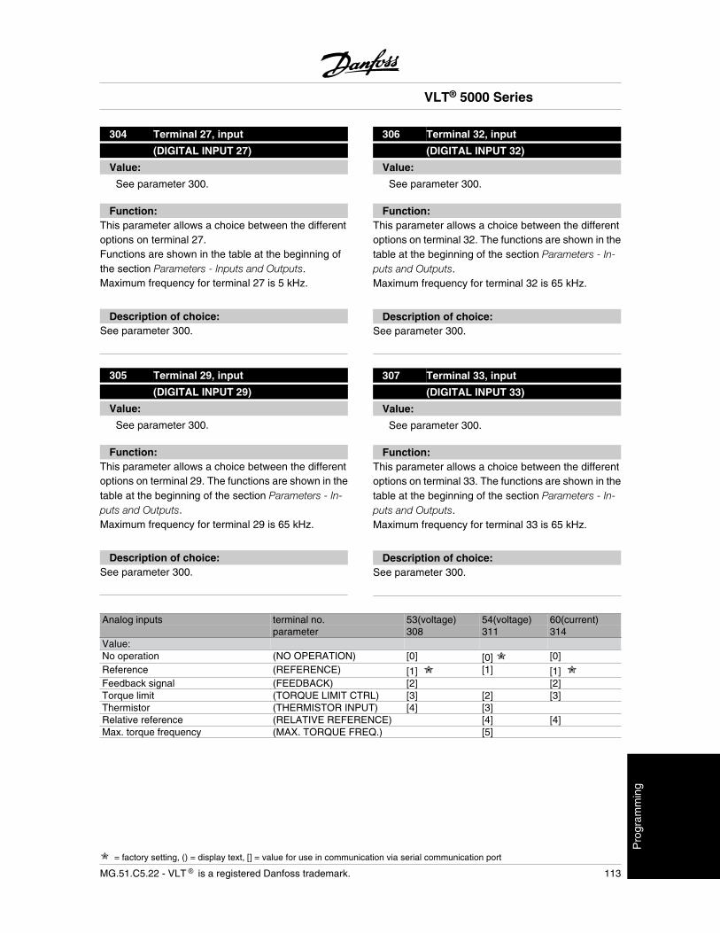
304 Terminal 27, input
(DIGITAL INPUT 27)
Value:
See parameter 300.
Function:This parameter allows a choice between the differentoptions on terminal 27.Functions are shown in the table at the beginning ofthe section Parameters - Inputs and Outputs.Maximum frequency for terminal 27 is 5 kHz.
Description of choice:See parameter 300.
305 Terminal 29, input
(DIGITAL INPUT 29)
Value:
See parameter 300.
Function:This parameter allows a choice between the differentoptions on terminal 29. The functions are shown in thetable at the beginning of the section Parameters - In-puts and Outputs.Maximum frequency for terminal 29 is 65 kHz.
Description of choice:See parameter 300.
306 Terminal 32, input
(DIGITAL INPUT 32)
Value:
See parameter 300.
Function:This parameter allows a choice between the differentoptions on terminal 32. The functions are shown in thetable at the beginning of the section Parameters - In-puts and Outputs.Maximum frequency for terminal 32 is 65 kHz.
Description of choice:See parameter 300.
307 Terminal 33, input
(DIGITAL INPUT 33)
Value:
See parameter 300.
Function:This parameter allows a choice between the differentoptions on terminal 33. The functions are shown in thetable at the beginning of the section Parameters - In-puts and Outputs.Maximum frequency for terminal 33 is 65 kHz.
Description of choice:See parameter 300.
Analog inputs terminal no. 53(voltage) 54(voltage) 60(current)parameter 308 311 314
Value:No operation (NO OPERATION) [0] [0] [0]Reference (REFERENCE) [1] [1] [1] Feedback signal (FEEDBACK) [2] [2]Torque limit (TORQUE LIMIT CTRL) [3] [2] [3]Thermistor (THERMISTOR INPUT) [4] [3]Relative reference (RELATIVE REFERENCE) [4] [4]Max. torque frequency (MAX. TORQUE FREQ.) [5]
VLT® 5000 Series
= factory setting, () = display text, [] = value for use in communication via serial communication port
MG.51.C5.22 - VLT is a registered Danfoss trademark. 113
Pro
gram
min
g
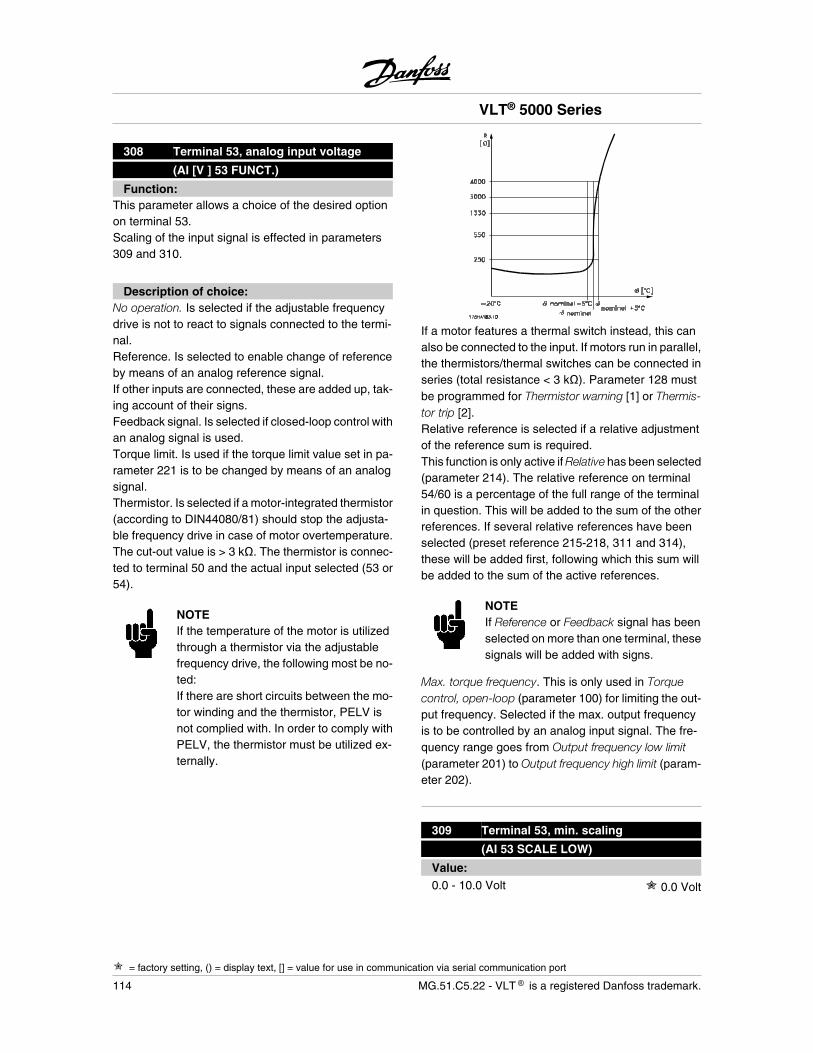
308 Terminal 53, analog input voltage
(AI [V ] 53 FUNCT.)
Function:This parameter allows a choice of the desired optionon terminal 53.Scaling of the input signal is effected in parameters309 and 310.
Description of choice:No operation. Is selected if the adjustable frequencydrive is not to react to signals connected to the termi-nal.Reference. Is selected to enable change of referenceby means of an analog reference signal.If other inputs are connected, these are added up, tak-ing account of their signs.Feedback signal. Is selected if closed-loop control withan analog signal is used.Torque limit. Is used if the torque limit value set in pa-rameter 221 is to be changed by means of an analogsignal.Thermistor. Is selected if a motor-integrated thermistor(according to DIN44080/81) should stop the adjusta-ble frequency drive in case of motor overtemperature.The cut-out value is > 3 k . The thermistor is connec-ted to terminal 50 and the actual input selected (53 or54).
NOTEIf the temperature of the motor is utilizedthrough a thermistor via the adjustablefrequency drive, the following most be no-ted:If there are short circuits between the mo-tor winding and the thermistor, PELV isnot complied with. In order to comply withPELV, the thermistor must be utilized ex-ternally.
If a motor features a thermal switch instead, this canalso be connected to the input. If motors run in parallel,the thermistors/thermal switches can be connected inseries (total resistance < 3 k ). Parameter 128 mustbe programmed for Thermistor warning [1] or Thermis-tor trip [2].Relative reference is selected if a relative adjustmentof the reference sum is required.This function is only active if Relative has been selected(parameter 214). The relative reference on terminal54/60 is a percentage of the full range of the terminalin question. This will be added to the sum of the otherreferences. If several relative references have beenselected (preset reference 215-218, 311 and 314),these will be added first, following which this sum willbe added to the sum of the active references.
NOTEIf Reference or Feedback signal has beenselected on more than one terminal, thesesignals will be added with signs.
Max. torque frequency. This is only used in Torquecontrol, open-loop (parameter 100) for limiting the out-put frequency. Selected if the max. output frequencyis to be controlled by an analog input signal. The fre-quency range goes from Output frequency low limit(parameter 201) to Output frequency high limit (param-eter 202).
309 Terminal 53, min. scaling
(AI 53 SCALE LOW)
Value:0.0 - 10.0 Volt 0.0 Volt
VLT® 5000 Series
= factory setting, () = display text, [] = value for use in communication via serial communication port
114 MG.51.C5.22 - VLT is a registered Danfoss trademark.
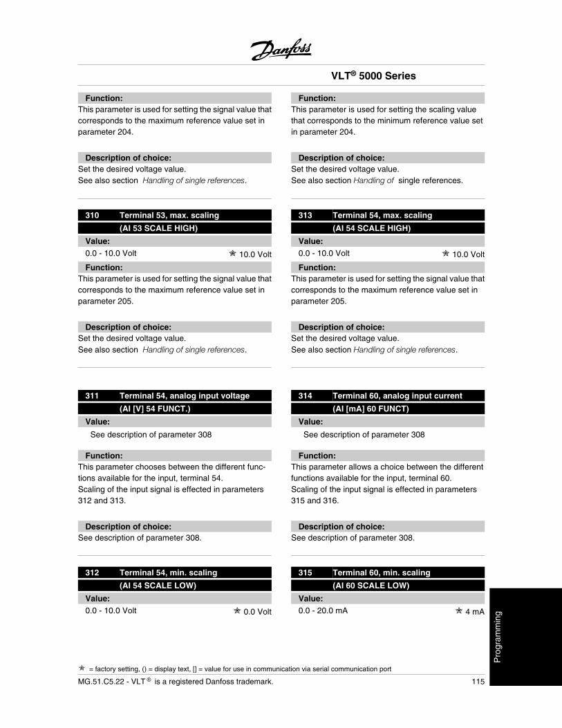
Function:This parameter is used for setting the signal value thatcorresponds to the maximum reference value set inparameter 204.
Description of choice:Set the desired voltage value.See also section Handling of single references.
310 Terminal 53, max. scaling
(AI 53 SCALE HIGH)
Value:0.0 - 10.0 Volt 10.0 Volt
Function:This parameter is used for setting the signal value thatcorresponds to the maximum reference value set inparameter 205.
Description of choice:Set the desired voltage value.See also section Handling of single references.
311 Terminal 54, analog input voltage
(AI [V] 54 FUNCT.)
Value:
See description of parameter 308
Function:This parameter chooses between the different func-tions available for the input, terminal 54.Scaling of the input signal is effected in parameters312 and 313.
Description of choice:See description of parameter 308.
312 Terminal 54, min. scaling
(AI 54 SCALE LOW)
Value:0.0 - 10.0 Volt 0.0 Volt
Function:This parameter is used for setting the scaling valuethat corresponds to the minimum reference value setin parameter 204.
Description of choice:Set the desired voltage value.See also section Handling of single references.
313 Terminal 54, max. scaling
(AI 54 SCALE HIGH)
Value:0.0 - 10.0 Volt 10.0 Volt
Function:This parameter is used for setting the signal value thatcorresponds to the maximum reference value set inparameter 205.
Description of choice:Set the desired voltage value.See also section Handling of single references.
314 Terminal 60, analog input current
(AI [mA] 60 FUNCT)
Value:
See description of parameter 308
Function:This parameter allows a choice between the differentfunctions available for the input, terminal 60.Scaling of the input signal is effected in parameters315 and 316.
Description of choice:See description of parameter 308.
315 Terminal 60, min. scaling
(AI 60 SCALE LOW)
Value:0.0 - 20.0 mA 4 mA
VLT® 5000 Series
= factory setting, () = display text, [] = value for use in communication via serial communication port
MG.51.C5.22 - VLT is a registered Danfoss trademark. 115
Pro
gram
min
g
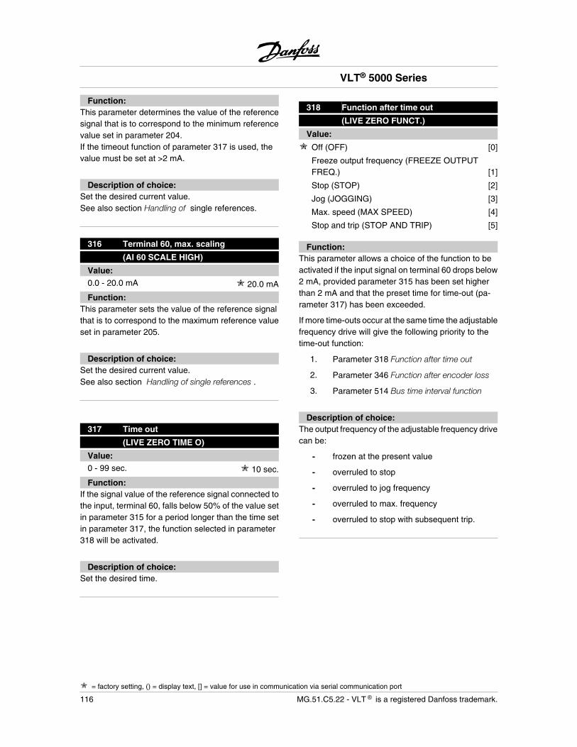
Function:This parameter determines the value of the referencesignal that is to correspond to the minimum referencevalue set in parameter 204.If the timeout function of parameter 317 is used, thevalue must be set at >2 mA.
Description of choice:Set the desired current value.See also section Handling of single references.
316 Terminal 60, max. scaling
(AI 60 SCALE HIGH)
Value:0.0 - 20.0 mA 20.0 mA
Function:This parameter sets the value of the reference signalthat is to correspond to the maximum reference valueset in parameter 205.
Description of choice:Set the desired current value.See also section Handling of single references .
317 Time out
(LIVE ZERO TIME O)
Value:0 - 99 sec. 10 sec.
Function:If the signal value of the reference signal connected tothe input, terminal 60, falls below 50% of the value setin parameter 315 for a period longer than the time setin parameter 317, the function selected in parameter318 will be activated.
Description of choice:Set the desired time.
318 Function after time out
(LIVE ZERO FUNCT.)
Value:
Off (OFF) [0]
Freeze output frequency (FREEZE OUTPUTFREQ.) [1]
Stop (STOP) [2]
Jog (JOGGING) [3]
Max. speed (MAX SPEED) [4]
Stop and trip (STOP AND TRIP) [5]
Function:This parameter allows a choice of the function to beactivated if the input signal on terminal 60 drops below2 mA, provided parameter 315 has been set higherthan 2 mA and that the preset time for time-out (pa-rameter 317) has been exceeded.
If more time-outs occur at the same time the adjustablefrequency drive will give the following priority to thetime-out function:
1. Parameter 318 Function after time out
2. Parameter 346 Function after encoder loss
3. Parameter 514 Bus time interval function
Description of choice:The output frequency of the adjustable frequency drivecan be:
- frozen at the present value
- overruled to stop
- overruled to jog frequency
- overruled to max. frequency
- overruled to stop with subsequent trip.
VLT® 5000 Series
= factory setting, () = display text, [] = value for use in communication via serial communication port
116 MG.51.C5.22 - VLT is a registered Danfoss trademark.
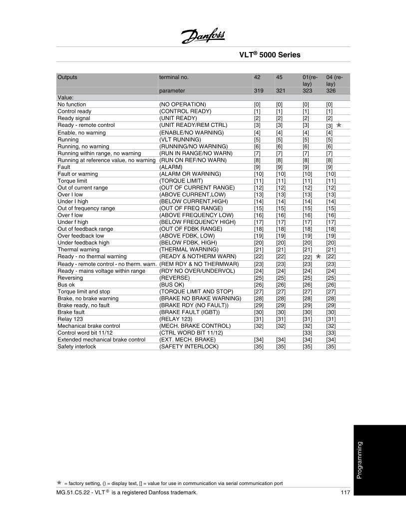
Outputs terminal no. 42 45 01(re-lay)
04 (re-lay)
parameter 319 321 323 326Value:No function (NO OPERATION) [0] [0] [0] [0]Control ready (CONTROL READY) [1] [1] [1] [1]Ready signal (UNIT READY) [2] [2] [2] [2]Ready - remote control (UNIT READY/REM CTRL) [3] [3] [3] [3]Enable, no warning (ENABLE/NO WARNING) [4] [4] [4] [4]Running (VLT RUNNING) [5] [5] [5] [5]Running, no warning (RUNNING/NO WARNING) [6] [6] [6] [6]Running within range, no warning (RUN IN RANGE/NO WARN) [7] [7] [7] [7]Running at reference value, no warning (RUN ON REF/NO WARN) [8] [8] [8] [8]Fault (ALARM) [9] [9] [9] [9]Fault or warning (ALARM OR WARNING) [10] [10] [10] [10]Torque limit (TORQUE LIMIT) [11] [11] [11] [11]Out of current range (OUT OF CURRENT RANGE) [12] [12] [12] [12]Over I low (ABOVE CURRENT,LOW) [13] [13] [13] [13]Under I high (BELOW CURRENT,HIGH) [14] [14] [14] [14]Out of frequency range (OUT OF FREQ RANGE) [15] [15] [15] [15]Over f low (ABOVE FREQUENCY LOW) [16] [16] [16] [16]Under f high (BELOW FREQUENCY HIGH) [17] [17] [17] [17]Out of feedback range (OUT OF FDBK RANGE) [18] [18] [18] [18]Over feedback low (ABOVE FDBK, LOW) [19] [19] [19] [19]Under feedback high (BELOW FDBK, HIGH) [20] [20] [20] [20]Thermal warning (THERMAL WARNING) [21] [21] [21] [21]Ready - no thermal warning (READY & NOTHERM WARN) [22] [22] [22] [22]Ready - remote control - no therm. warn. (REM RDY & NO THERMWAR) [23] [23] [23] [23]Ready - mains voltage within range (RDY NO OVER/UNDERVOL) [24] [24] [24] [24]Reversing (REVERSE) [25] [25] [25] [25]Bus ok (BUS OK) [26] [26] [26] [26]Torque limit and stop (TORQUE LIMIT AND STOP) [27] [27] [27] [27]Brake, no brake warning (BRAKE NO BRAKE WARNING) [28] [28] [28] [28]Brake ready, no fault (BRAKE RDY (NO FAULT)) [29] [29] [29] [29]Brake fault (BRAKE FAULT (IGBT)) [30] [30] [30] [30]Relay 123 (RELAY 123) [31] [31] [31] [31]Mechanical brake control (MECH. BRAKE CONTROL) [32] [32] [32] [32]Control word bit 11/12 (CTRL WORD BIT 11/12) [33] [33]Extended mechanical brake control (EXT. MECH. BRAKE) [34] [34] [34] [34]Safety interlock (SAFETY INTERLOCK) [35] [35] [35] [35]
VLT® 5000 Series
= factory setting, () = display text, [] = value for use in communication via serial communication port
MG.51.C5.22 - VLT is a registered Danfoss trademark. 117
Pro
gram
min
g
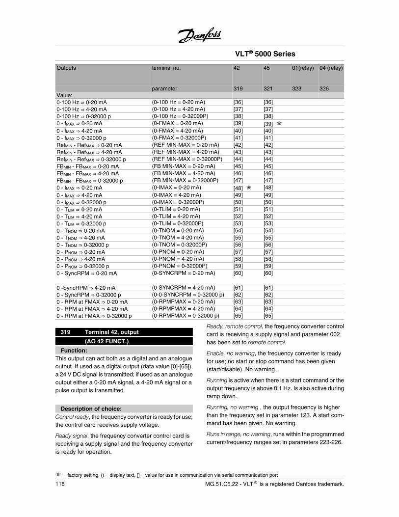
Outputs terminal no. 42 45 01(relay) 04 (relay)
parameter 319 321 323 326Value:0-100 Hz 0-20 mA (0-100 Hz = 0-20 mA) [36] [36]0-100 Hz 4-20 mA (0-100 Hz = 4-20 mA) [37] [37]0-100 Hz 0-32000 p (0-100 Hz = 0-32000P) [38] [38]0 - fMAX 0-20 mA (0-FMAX = 0-20 mA) [39] [39] 0 - fMAX 4-20 mA (0-FMAX = 4-20 mA) [40] [40]0 - fMAX 0-32000 p (0-FMAX = 0-32000P) [41] [41]RefMIN - RefMAX 0-20 mA (REF MIN-MAX = 0-20 mA) [42] [42]RefMIN - RefMAX 4-20 mA (REF MIN-MAX = 4-20 mA) [43] [43]RefMIN - RefMAX 0-32000 p (REF MIN-MAX = 0-32000P) [44] [44]FBMIN - FBMAX 0-20 mA (FB MIN-MAX = 0-20 mA) [45] [45]FBMIN - FBMAX 4-20 mA (FB MIN-MAX = 4-20 mA) [46] [46]FBMIN - FBMAX 0-32000 p (FB MIN-MAX = 0-32000P) [47] [47]0 - IMAX 0-20 mA (0-IMAX = 0-20 mA) [48] [48]0 - IMAX 4-20 mA (0-IMAX = 4-20 mA) [49] [49]0 - IMAX 0-32000 p (0-IMAX = 0-32000P) [50] [50]0 - TLIM 0-20 mA (0-TLIM = 0-20 mA) [51] [51]0 - TLIM 4-20 mA (0-TLIM = 4-20 mA) [52] [52]0 - TLIM 0-32000 p (0-TLIM = 0-32000P) [53] [53]0 - TNOM 0-20 mA (0-TNOM = 0-20 mA) [54] [54]0 - TNOM 4-20 mA (0-TNOM = 4-20 mA) [55] [55]0 - TNOM 0-32000 p (0-TNOM = 0-32000P) [56] [56]0 - PNOM 0-20 mA (0-PNOM = 0-20 mA) [57] [57]0 - PNOM 4-20 mA (0-PNOM = 4-20 mA) [58] [58]0 - PNOM 0-32000 p (0-PNOM = 0-32000P) [59] [59]0 - SyncRPM 0-20 mA (0-SYNCRPM = 0-20 mA) [60] [60]
0 -SyncRPM 4-20 mA (0-SYNCRPM = 4-20 mA) [61] [61]0 - SyncRPM 0-32000 p (0-0-SYNCRPM = 0-32000 p) [62] [62]0 - RPM at FMAX 0-20 mA (0-RPMFMAX = 0-20 mA) [63] [63]0 - RPM at FMAX 4-20 mA (0-RPMFMAX = 4-20 mA) [64] [64]0 - RPM at FMAX 0-32000 p (0-RPMFMAX = 0-32000 p) [65] [65]
319 Terminal 42, output
(AO 42 FUNCT.)
Function:This output can act both as a digital and an analogueoutput. If used as a digital output (data value [0]-[65]),a 24 V DC signal is transmitted; if used as an analogueoutput either a 0-20 mA signal, a 4-20 mA signal or apulse output is transmitted.
Description of choice:Control ready, the frequency converter is ready for use;the control card receives supply voltage.
Ready signal, the frequency converter control card isreceiving a supply signal and the frequency converteris ready for operation.
Ready, remote control, the frequency converter controlcard is receiving a supply signal and parameter 002has been set to remote control.
Enable, no warning, the frequency converter is readyfor use; no start or stop command has been given(start/disable). No warning.
Running is active when there is a start command or theoutput frequency is above 0.1 Hz. Is also active duringramp down.
Running, no warning , the output frequency is higherthan the frequency set in parameter 123. A start com-mand has been given. No warning.
Runs in range, no warning, runs within the programmedcurrent/frequency ranges set in parameters 223-226.
VLT® 5000 Series
= factory setting, () = display text, [] = value for use in communication via serial communication port
118 MG.51.C5.22 - VLT is a registered Danfoss trademark.
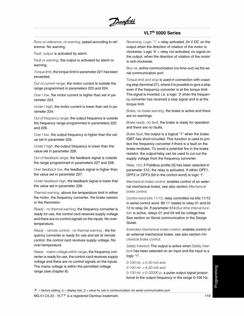
Runs on reference, no warning, speed according to ref-erence. No warning.
Fault, output is activated by alarm.
Fault or warning, the output is activated by alarm orwarning.
Torque limit, the torque limit in parameter 221 has beenexceeded.
Out of current range, the motor current is outside therange programmed in parameters 223 and 224.
Over I low, the motor current is higher than set in pa-rameter 223.
Under I high, the motor current is lower than set in pa-rameter 224.
Out of frequency range, the output frequency is outsidethe frequency range programmed in parameters 225and 226.
Over f low, the output frequency is higher than the val-ue set in parameter 225.
Under f high, the output frequency is lower than thevalue set in parameter 226.
Out of feedback range, the feedback signal is outsidethe range programmed in parameters 227 and 228.
Over feedback low, the feedback signal is higher thanthe value set in parameter 227.
Under feedback high, the feedback signal is lower thatthe value set in parameter 228.
Thermal warning, above the temperature limit in eitherthe motor, the frequency converter, the brake resistoror the thermistor.
Ready - no thermal warning, the frequency converter isready for use, the control card receives supply voltageand there are no control signals on the inputs. No over-temperature.
Ready - remote control - no thermal warning , the fre-quency converter is ready for use and set at remotecontrol, the control card receives supply voltage. Noover-temperature.
Ready - mains voltage within range, the frequency con-verter is ready for use, the control card receives supplyvoltage and there are no control signals on the inputs.The mains voltage is within the permitted voltagerange (see chapter 8).
Reversing. Logic '1' = relay activated, 24 V DC on theoutput when the direction of rotation of the motor isclockwise. Logic '0' = relay not activated, no signal onthe output, when the direction of rotation of the motoris anti-clockwise.
Bus-ok, active communication (no time-out) via the se-rial communication port.
Torque limit and stop is used in connection with coast-ing stop (terminal 27), where it is possible to give a stopeven if the frequency converter is at the torque limit.The signal is inverted, i.e. a logic ̀ 0' when the frequen-cy converter has received a stop signal and is at thetorque limit.
Brake, no brake warning, the brake is active and thereare no warnings.
Brake ready, no fault, the brake is ready for operationand there are no faults.
Brake fault, the output is a logical "1" when the brakeIGBT has short-circuited. This function is used to pro-tect the frequency converter if there is a fault on thebrake modules. To avoid a potential fire in the brakeresistor, the output/relay can be used to cut out thesupply voltage from the frequency converter.
Relay 123, if Fieldbus profile [0] has been selected inparameter 512, the relay is activated. If either OFF1,OFF2 or OFF3 (bit in the control word) is logic '1'.
Mechanical brake control, enables control of an exter-nal mechanical brake, see also section Mechanicalbrake control.
Control word bits 11/12, relay controlled via bits 11/12in serial control word. Bit 11 relates to relay 01 and bit12 to relay 04. If parameter 514 Bus time interval func-tion is active, relays 01 and 04 will be voltage-free.See section on Serial communication in the DesignGuide.
Extended mechanical brake control, enables control ofan external mechanical brake, see also section Me-chanical brake control.
Safety interlock The output is active when Safety inter-lock has been selected on an input and the input is alogic “1”.
0-100 Hz 0-20 mA and0-100 Hz 4-20 mA and0-100 Hz 0-32000 p, a pulse output signal propor-tional to the output frequency in the range 0-100 Hz.
VLT® 5000 Series
= factory setting, () = display text, [] = value for use in communication via serial communication port
MG.51.C5.22 - VLT is a registered Danfoss trademark. 119
Pro
gram
min
g
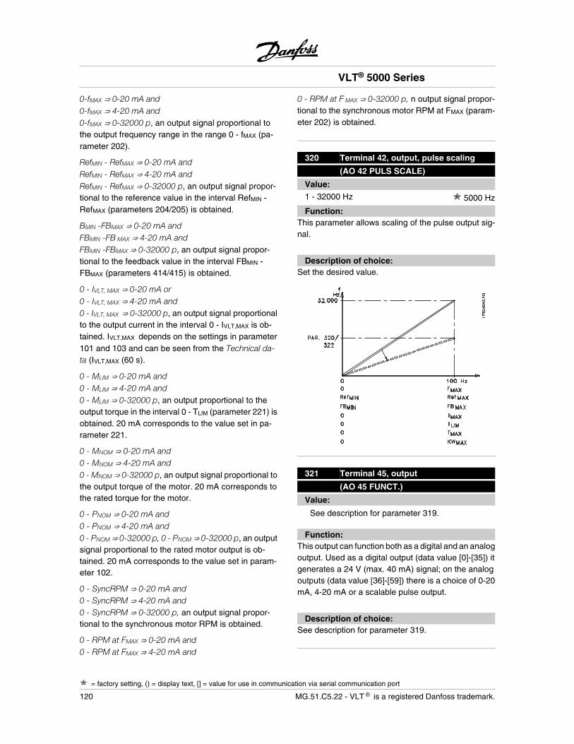
0-fMAX 0-20 mA and0-fMAX 4-20 mA and0-fMAX 0-32000 p, an output signal proportional tothe output frequency range in the range 0 - fMAX (pa-rameter 202).
RefMIN - RefMAX 0-20 mA andRefMIN - RefMAX 4-20 mA andRefMIN - RefMAX 0-32000 p, an output signal propor-tional to the reference value in the interval RefMIN -RefMAX (parameters 204/205) is obtained.
BMIN -FBMAX 0-20 mA andFBMIN -FB MAX 4-20 mA andFBMIN -FBMAX 0-32000 p, an output signal propor-tional to the feedback value in the interval FBMIN -FBMAX (parameters 414/415) is obtained.
0 - IVLT, MAX 0-20 mA or0 - IVLT, MAX 4-20 mA and0 - IVLT, MAX 0-32000 p, an output signal proportionalto the output current in the interval 0 - IVLT,MAX is ob-tained. IVLT,MAX depends on the settings in parameter101 and 103 and can be seen from the Technical da-ta (IVLT,MAX (60 s).
0 - MLIM 0-20 mA and0 - MLIM 4-20 mA and0 - MLIM 0-32000 p, an output proportional to theoutput torque in the interval 0 - TLIM (parameter 221) isobtained. 20 mA corresponds to the value set in pa-rameter 221.
0 - MNOM 0-20 mA and0 - MNOM 4-20 mA and0 - MNOM 0-32000 p, an output signal proportional tothe output torque of the motor. 20 mA corresponds tothe rated torque for the motor.
0 - PNOM 0-20 mA and0 - PNOM 4-20 mA and0 - PNOM 0-32000 p, 0 - PNOM 0-32000 p, an outputsignal proportional to the rated motor output is ob-tained. 20 mA corresponds to the value set in param-eter 102.
0 - SyncRPM 0-20 mA and0 - SyncRPM 4-20 mA and0 - SyncRPM 0-32000 p, an output signal propor-tional to the synchronous motor RPM is obtained.
0 - RPM at FMAX 0-20 mA and0 - RPM at FMAX 4-20 mA and
0 - RPM at F MAX 0-32000 p, n output signal propor-tional to the synchronous motor RPM at FMAX (param-eter 202) is obtained.
320 Terminal 42, output, pulse scaling
(AO 42 PULS SCALE)
Value:1 - 32000 Hz 5000 Hz
Function:This parameter allows scaling of the pulse output sig-nal.
Description of choice:Set the desired value.
321 Terminal 45, output
(AO 45 FUNCT.)
Value:
See description for parameter 319.
Function:This output can function both as a digital and an analogoutput. Used as a digital output (data value [0]-[35]) itgenerates a 24 V (max. 40 mA) signal; on the analogoutputs (data value [36]-[59]) there is a choice of 0-20mA, 4-20 mA or a scalable pulse output.
Description of choice:See description for parameter 319.
VLT® 5000 Series
= factory setting, () = display text, [] = value for use in communication via serial communication port
120 MG.51.C5.22 - VLT is a registered Danfoss trademark.
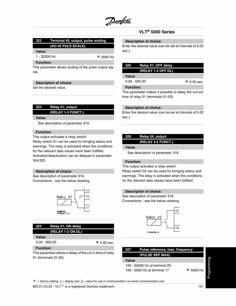
322 Terminal 45, output, pulse scaling
(AO 45 PULS SCALE)
Value:1 - 32000 Hz 5000 Hz
Function:This parameter allows scaling of the pulse output sig-nal.
Description of choice:Set the desired value.
323 Relay 01, output
(RELAY 1-3 FUNCT.)
Value:
See description of parameter 319.
Function:This output activates a relay switch.Relay switch 01 can be used for bringing status andwarnings. The relay is activated when the conditionsfor the relevant data values have been fulfilled.Activation/deactivation can be delayed in parameter324/325.
Description of choice:See description of parameter 319.Connections - see the below drawing.
324 Relay 01, ON delay
(RELAY 1-3 ON DL)
Value:0.00 - 600.00. 0.00 sec.
Function:This parameter allows a delay of the cut-in time of relay01 (terminals 01-02).
Description of choice:Enter the desired value (can be set at intervals of 0.02sec.).
325 Relay 01, OFF delay
(RELAY 1-3 OFF DL)
Value:0.00 - 600.00 0.00 sec.
Function:This parameter makes it possible to delay the cut-outtime of relay 01 (terminals 01-03).
Description of choice:Enter the desired value (can be set at intervals of 0.02sec.).
326 Relay 04, output
(RELAY 4-5 FUNCT.)
Value:
See description of parameter 319.
Function:This output activates a relay switch.Relay switch 04 can be used for bringing status andwarnings. The relay is activated when the conditionsfor the relevant data values have been fulfilled.
Description of choice:See description of parameter 319.Connections - see the below drawing.
327 Pulse reference, max. frequency
(PULSE REF MAX)
Value:100 - 65000 Hz at terminal 29100 - 5000 Hz at terminal 17 5000 Hz
VLT® 5000 Series
= factory setting, () = display text, [] = value for use in communication via serial communication port
MG.51.C5.22 - VLT is a registered Danfoss trademark. 121
Pro
gram
min
g
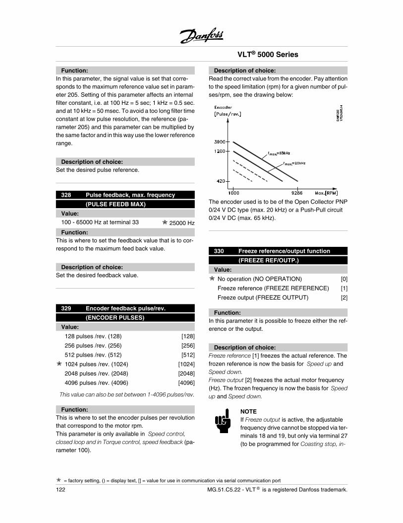
Function:In this parameter, the signal value is set that corre-sponds to the maximum reference value set in param-eter 205. Setting of this parameter affects an internalfilter constant, i.e. at 100 Hz = 5 sec; 1 kHz = 0.5 sec.and at 10 kHz = 50 msec. To avoid a too long filter timeconstant at low pulse resolution, the reference (pa-rameter 205) and this parameter can be multiplied bythe same factor and in this way use the lower referencerange.
Description of choice:Set the desired pulse reference.
328 Pulse feedback, max. frequency
(PULSE FEEDB MAX)
Value:100 - 65000 Hz at terminal 33 25000 Hz
Function:This is where to set the feedback value that is to cor-respond to the maximum feed back value.
Description of choice:Set the desired feedback value.
329 Encoder feedback pulse/rev.
(ENCODER PULSES)
Value:
128 pulses /rev. (128) [128]
256 pulses /rev. (256) [256]
512 pulses /rev. (512) [512]
1024 pulses /rev. (1024) [1024]
2048 pulses /rev. (2048) [2048]
4096 pulses /rev. (4096) [4096]
This value can also be set between 1-4096 pulses/rev.
Function:This is where to set the encoder pulses per revolutionthat correspond to the motor rpm.This parameter is only available in Speed control,closed loop and in Torque control, speed feedback (pa-rameter 100).
Description of choice:Read the correct value from the encoder. Pay attentionto the speed limitation (rpm) for a given number of pul-ses/rpm, see the drawing below:
The encoder used is to be of the Open Collector PNP0/24 V DC type (max. 20 kHz) or a Push-Pull circuit0/24 V DC (max. 65 kHz).
330 Freeze reference/output function
(FREEZE REF/OUTP.)
Value:
No operation (NO OPERATION) [0]
Freeze reference (FREEZE REFERENCE) [1]
Freeze output (FREEZE OUTPUT) [2]
Function:In this parameter it is possible to freeze either the ref-erence or the output.
Description of choice:Freeze reference [1] freezes the actual reference. Thefrozen reference is now the basis for Speed up andSpeed down.Freeze output [2] freezes the actual motor frequency(Hz). The frozen frequency is now the basis for Speedup and Speed down.
NOTEIf Freeze output is active, the adjustablefrequency drive cannot be stopped via ter-minals 18 and 19, but only via terminal 27(to be programmed for Coasting stop, in-
VLT® 5000 Series
= factory setting, () = display text, [] = value for use in communication via serial communication port
122 MG.51.C5.22 - VLT is a registered Danfoss trademark.
verse [0] or Reset and coasting stop, in-verse [1]).
After Freeze output, the PID integrators are reset.
345 Encoder loss timeout
(ENC LOSS TIMEOUT)
Value:0 - 60 sec. 1 sec.
Function:If the encoder signal is interrupted from terminal 32 or33 the function selected in parameter 346 will be acti-vated.If the encoder feedback signal is different from the out-put frequency +/- 3 x nominal motor slip the encoderloss function will be activated.An encoder loss timeout can occur even if the encoderworks all right. Check the motor parameter in group100 if no error can be found on the encoder.The Encoder loss function is only active in Speed con-trol, closed loop [1] and Torque control, speed feed-back [5], see parameter 100 Configuration.
Description of choice:Set the required time.
346 Encoder loss function
(ENC. LOSS FUNC)
Value:
Off (OFF) [0]
Freeze output frequency (FREEZE OUTPUTFREQ.) [1]
Jog (JOGGING) [3]
Max. speed (MAX SPEED) [4]
Stop and trip (STOP AND TRIP) [5]
Select Setup 4 (SELECT SETUP 4) [7]
Function:In this parameter the function can be activated if theencoder signal is disconnected from terminal 32 or 33.
If more time-outs occur at the same time the adjustablefrequency drive will give the following priority to thetime-out function:
1. Parameter 318 Function after time out
2. Parameter 346 Function after encoder loss
3. Parameter 514 Bus time interval function.
Description of choice:The output frequency of the adjustable frequency drivecan be:
- frozen at the present value
- overruled to jog frequency
- overruled to max. frequency
- overruled to stop with subsequent trip
- overruled to Setup 4.
357 Terminal 42, Output minimum scaling
(out 42 scal min)359 Terminal 45, Output minimum scaling
(out 45 scal min)
Value:000 - 100% 0%
Function:These parameters are to scale the minimum output ofthe selected analog/pulse signal on terminals 42 and45.
Description of choice:The minimum value is to be scaled as a percentage ofthe maximum signal value, i.e. 0mA (or 0 Hz) is desiredat 25% of the maximum output value, and then 25% isprogrammed.The value can never be higher than the correspondingsetting of Output maximum scaling if this value is below100%.
VLT® 5000 Series
= factory setting, () = display text, [] = value for use in communication via serial communication port
MG.51.C5.22 - VLT is a registered Danfoss trademark. 123
Pro
gram
min
g
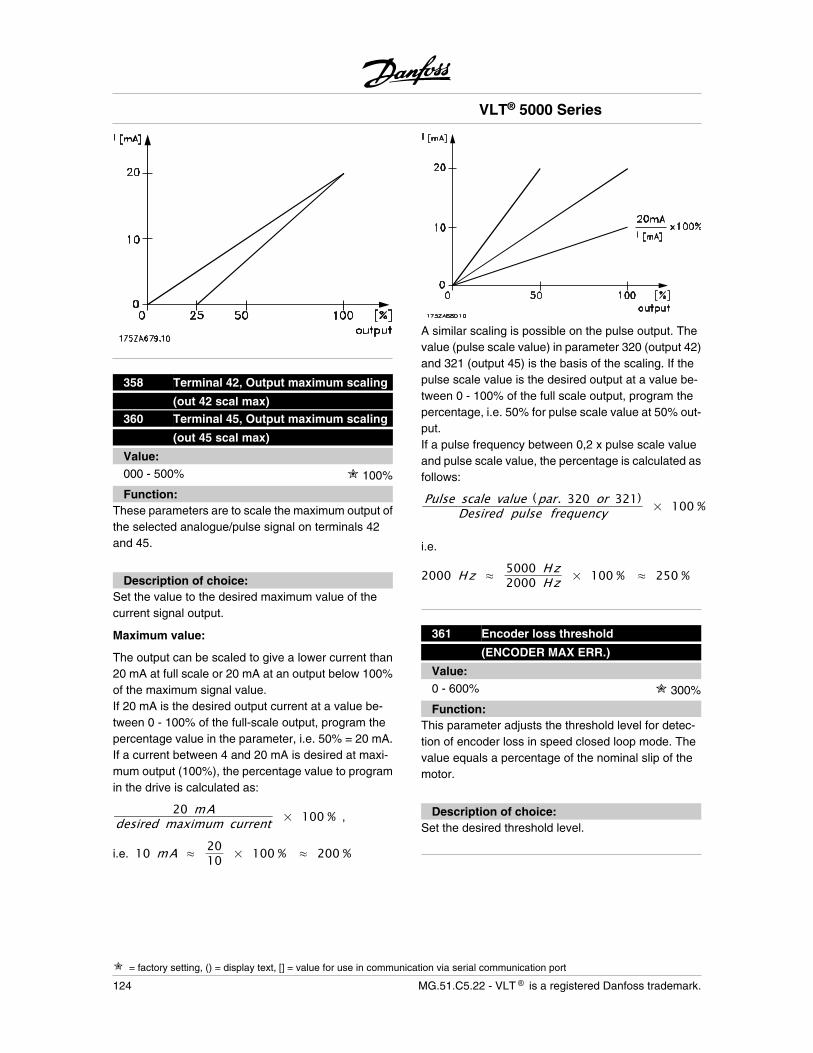
358 Terminal 42, Output maximum scaling
(out 42 scal max)360 Terminal 45, Output maximum scaling
(out 45 scal max)
Value:000 - 500% 100%
Function:These parameters are to scale the maximum output ofthe selected analogue/pulse signal on terminals 42and 45.
Description of choice:Set the value to the desired maximum value of thecurrent signal output.
Maximum value:
The output can be scaled to give a lower current than20 mA at full scale or 20 mA at an output below 100%of the maximum signal value.If 20 mA is the desired output current at a value be-tween 0 - 100% of the full-scale output, program thepercentage value in the parameter, i.e. 50% = 20 mA.If a current between 4 and 20 mA is desired at maxi-mum output (100%), the percentage value to programin the drive is calculated as:
20 mAdesired maximum current × 100 % ,
i.e. 10 mA 2010 × 100 % 200 %
A similar scaling is possible on the pulse output. Thevalue (pulse scale value) in parameter 320 (output 42)and 321 (output 45) is the basis of the scaling. If thepulse scale value is the desired output at a value be-tween 0 - 100% of the full scale output, program thepercentage, i.e. 50% for pulse scale value at 50% out-put.If a pulse frequency between 0,2 x pulse scale valueand pulse scale value, the percentage is calculated asfollows:
Pulse scale value (par. 320 or 321)Desired pulse frequency × 100 %
i.e.
2000 Hz 5000 Hz2000 Hz × 100 % 250 %
361 Encoder loss threshold
(ENCODER MAX ERR.)
Value:0 - 600% 300%
Function:This parameter adjusts the threshold level for detec-tion of encoder loss in speed closed loop mode. Thevalue equals a percentage of the nominal slip of themotor.
Description of choice:Set the desired threshold level.
VLT® 5000 Series
= factory setting, () = display text, [] = value for use in communication via serial communication port
124 MG.51.C5.22 - VLT is a registered Danfoss trademark.
Special functions
400 Brake function/overvoltage control
(BRAKE FUNCTION)
Value:
Off (OFF) [0]
Resistor brake (RESISTOR) [1]
Overvoltage control (OVERVOLTAGE CON-TROL) [2]
Overvoltage control and stop(OVERVOLT CTRL. & STOP) [3]
Function:The factory setting is Off [0] for VLT 5001-5027200-240 V, VLT 5001-5102 380-500 V and VLT5001-5062 525-600 V. For VLT 5032-5052 200-240 V,5122-5552 380-500 V and VLT 5042-5602 525-690 Vthe factory setting is Overvoltage control [2].Resistor brake [1] is used for programming the adjust-able frequency drive for connection of a brake resistor.The connection of a brake resistor allows a higher in-termediate circuit voltage during braking (generatingoperation).The Resistor brake [1] function is only active in unitswith an integral dynamic brake (SB and EB units).
Overvoltage control (excl. brake resistor) can be selec-ted as an alternative. This function is active for all units(ST, SB and EB).
The function ensures that a trip can be avoided if theintermediate circuit voltage increases. This is done byincreasing the output frequency to limit the voltagefrom the intermediate circuit. This is a very useful func-tion, e.g. if the ramp-down time is too short, sincetripping of the adjustable frequency drive is avoided.In this situation, the ramp-down time is extended.
NOTEPlease note that the ramp-down time isextended in the case of overvoltage con-trol, which in some applications may notbe appropriate.
Description of choice:Select Resistor brake [1] if a brake resistor is part of thesystem.Select Overvoltage control [2] if the overvoltage controlfunction is required in all cases - also if stop is pressed.
The adjustable frequency drive will not stop in the caseof a stop command when the overvoltage control isactive.Select Overvoltage control and stop [3] if the overvolt-age control function is not required during ramp-downafter stop has been pressed.
Warning: If Overvoltage control [2] is usedat the same time as the supply voltage tothe adjustable frequency drive is close toor above the maximum limit, there is a riskthat the motor frequency will increase andthat, consequently, the adjustable fre-quency drive will not stop the motor whenstop is pressed. If the supply voltage ishigher than:
• 264 V for 200-240 V units
• 550 V for 380-500 V units
• 660 V for 525-600 V units
• 759 V for 525-690 V units
Overvoltage control and stop [3] should beselected so that the motor can be stopped.
401 Brake resistor, ohm
(BRAKE RES. (OHM))
Value:Depends on the unit Depends on the unit
Function:This parameter gives the ohmic value of the brake re-sistor. This value is used for monitoring the power tothe brake resistor provided this function has been se-lected in parameter 403.
Description of choice:Set the present resistor value.
402 Braking energy limit, kW
(BR.POWER. LIM.KW)
Value:Depends on the unit Depends on the unit
VLT® 5000 Series
= factory setting, () = display text, [] = value for use in communication via serial communication port
MG.51.C5.22 - VLT is a registered Danfoss trademark. 125
Pro
gram
min
g
Function:This parameter gives the monitoring limit of the powertransmitted to the brake resistor.
Description of choice:The monitoring limit is determined as a product of themaximum duty cycle (120 sec.) that will occur and themaximum power of the brake resistor at that duty cycleaccording to the following formula.
For 200-240 V units: P = 3972 × tR × 120
For 380 - 500 V units: P = 8222 × tR × 120
For 525 - 600 V units: P = 9582 × tR × 120
For 525 - 690 V units: P = 10842 × tR × 120
403 Power monitoring
(POWER MONITORING)
Value:
Off (OFF) [0]
Warning (Warning) [1]
Trip (TRIP) [2]
Function:This parameter allows monitoring of the power trans-mitted to the brake resistor. The power is calculatedon the basis of the resistor ohm value (parameter 401),the intermediate circuit voltage and the resistor run-ning time. If the power transmitted over 120 sec. ex-ceeds 100% of the monitoring limit (parameter 402)and Warning [1] has been selected, a warning willcome up on the display. The warning will disappear ifthe power goes below 80%. If the calculated powerexceeds 100% of the monitoring limit and Trip [2] hasbeen selected in parameter 403 Power monitoring, theadjustable frequency drive will cut out while giving analarm. If power monitoring has been selected as Off [0]or Warning [1], the brake function will remain active,even if the monitoring limit has been exceeded.Thismay lead to thermal overload of the resis tor. It is alsopossible to have a warning via the relay/digital outputs.The typical measuring accuracy of the power monitor-
ing depends on the accuracy of the resistor ohmicvalue (better than ± 20%).
NOTEThe power dissipation during quick dis-charge does not form part of the powermonitoring function.
Description of choice:Select whether this function is to be active ( Warning/Alarm) or inactive (Off).
404 Brake check
(BRAKE TEST)
Value:
Off (OFF) [0]
Warning (WARNING) [1]
Trip (TRIP) [2]
Function:In this parameter a testing and monitoring function canbe integrated which will give a warning or an alarm. Onpower-up it will be tested whether the brake resistor isdisconnected. The test of whether the brake resistor isdisconnected is carried out during braking, while thetest of whether the IGBT is disconnected is carried outwhen there is no braking. A warning or trip disconnectsthe brake function.The testing sequence is as follows:
1. If the intermediate circuit voltage is higherthan the brake starting voltage, discontinuethe brake check.
2. If the intermediate circuit voltage is unstable,discontinue the brake check.
3. Carry out a brake test.
4. If the intermediate circuit voltage is lowerthan the starting voltage, discontinue thebrake check.
5. If the intermediate circuit voltage is unstable,discontinue the brake check.
6. If the braking power is higher than 100%, dis-continue the brake check.
VLT® 5000 Series
= factory setting, () = display text, [] = value for use in communication via serial communication port
126 MG.51.C5.22 - VLT is a registered Danfoss trademark.
7. If the intermediate circuit voltage is higherthan the intermediate circuit voltage -2% be-fore the brake test, discontinue the brakecheck and give off a warning or alarm.
8. Brake check OK.
Description of choice:If Off [0] is selected, this function will still monitorwhether the brake resistor and the brake IGBT short-circuit during operation, in which case it will give off awarning. If Warning [1] is selected, the brake resistorand brake IGBT will be monitored with respect to short-circuiting. In addition, on power-up it will be checkedwhether the brake resistor has been disconnected.
NOTEA warning in connection with Off [0] orWarning [1] can only be removed by dis-connecting the mains supply and turningit back on, provided the fault has beencorrected. Please note that in connectionwith Off [0] or Warning [1] the adjustablefrequency drive will continue even if a faulthas been found.
In the case of Trip [2], the adjustable frequency drivewill cut out while giving an alarm (trip locked) if thebrake resistor has short-circuited or been disconnec-ted or if the brake IGBT has short-circuited.
405 Reset function (RESET MODE)
Value:
Manual reset (MANUAL RESET) [0]
Automatic reset x 1 (AUTOMATIC X 1) [1]
Automatic reset x 2 (AUTOMATIC X 2) [2]
Automatic reset x 3 (AUTOMATIC X 3) [3]
Automatic reset x 4 (AUTOMATIC X 4) [4]
Automatic reset x 5 (AUTOMATIC X 5) [5]
Automatic reset x 6 (AUTOMATIC X 6) [6]
Automatic reset x 7 (AUTOMATIC X 7) [7]
Automatic reset x 8 (AUTOMATIC X 8) [8]
Automatic reset x 9 (AUTOMATIC X 9) [9]
Automatic reset x 10 (AUTOMATIC X 10) [10]
Function:This parameter makes it possible to select the resetfunction desired after tripping.After reset, the adjustable frequency drive can be re-started.
Description of choice:If Manual reset [0] is selected, reset must be effectedvia the [RESET] key or via the digital inputs.If the adjustable frequency drive is to carry out an au-tomatic reset (1-10 times) after tripping, select datavalue [1]-[10].
NOTEThe internal AUTOMATIC RESET coun-ter is reset 10 minutes after the first AU-TOMATIC RESET has occurred.
Warning: The motor may start withoutwarning.
406 Automatic restart time
(AUT RESTART TIME)
Value:0 - 10 sec. 5 sec.
Function:This parameter allows setting of the time from trippinguntil the automatic reset function begins.It is assumed that automatic reset has been selectedin parameter 405.
Description of choice:Set the desired time.
407 Mains failure
(MAINS FAILURE)
Value:
No function (NO FUNCTION) [0]
Controlled ramp-down(CONTROL RAMP DOWN) [1]
Controlled ramp-down and trip(CTRL. RAMP DOWN-TRIP) [2]
VLT® 5000 Series
= factory setting, () = display text, [] = value for use in communication via serial communication port
MG.51.C5.22 - VLT is a registered Danfoss trademark. 127
Pro
gram
min
g
Coasting (COASTING) [3]
Kinetic back-up (KINETIC BACKUP) [4]
Controlled alarm suppression(ctrl alarm supp) [5]
Function:Using the mains failure function, it is possible to rampdown the load to 0 Hz if the mains supply to the ad-justable frequency drive fails.In parameter 450 Mains voltage during mains fault, thevoltage limit must be set at which the Mains fault func-tion is to be active.This function can also be activated by selecting Mainsfailure inverted on a digital input.When Kinetic backup [4] is selected, the ramp functionin parameter 206-212 is deactivated.Controlled ramp down and kinetic back up have limitedperfomance above 70% load.
Description of choice:Select No function [0] if this function is not required. IfControlled ramp-down [1] is selected, the motor willramp via the quick-stop ramp set in parameter 212. Ifthe supply voltage is re-established during ramp-down, the adjustable frequency drive will start upagain. If Controlled ramp-down and trip [2] is selected,the motor will ramp via the quick-stop ramp set in pa-rameter 212.At 0 Hz the adjustable frequency drive will trip (ALARM36, mains failure). If the supply voltage is re-establish-ed during ramp-down, the adjustable frequency drivewill continue the quick-stop ramp and trip. If Coast-ing [3] is selected, the adjustable frequency drive willturn off the inverters and the motor will start coasting.Parameter 445 Flying motor must be active, so that ifthe supply voltage is re-established, the adjustablefrequency drive will be able to catch the motor and startup again.If Kinetic back-up [4] is selected, the adjustable fre-quency drive will try to utilise the energy from the loadto maintain a constant intermediate circuit voltage. Ifthe supply voltage is re-established, the adjustablefrequency drive will start up again.If Controlled alarm suppression [5] is selected, the ad-justable frequency drive will trip if there is a mainsfailure and the unit is not stopped by OFF1, OFF2 orOFF3 via the Profibus. Only active with Fieldbus profile(par. 512) selected and Profibus installed.
408 Quick discharge
(QUICK DISCHARGE)
Value:
Not possible (DISABLE) [0]
Possible (ENABLE) [1]
Function:The option is given of quickly discharging the inter-mediate circuit capacitors by means of an externalresistor.
Description of choice:This function is only active in extended units, since itrequires the connection of external 24 V DC and abrake resistor or discharge resistor; otherwise, the da-ta selection is limited to Disable [0].This function can be activated by selecting a digital in-put signal for Mains failure inverted . Select Disable ifthis function is not required. Select Enable and connect24 V DC external supply and a brake/discharge resis-tor.See section Quick discharge.
409 Trip delay torque
(TRIP DELAY TORQ.)
Value:0 - 60 sec. (OFF) OFF
Function:When the adjustable frequency drive registers that theoutput torque has increased up to the torque limits(parameters 221 and 222) in the set time, cutting outis effected when that time has passed.
Description of choice:Select how long the adjustable frequency drive is to beable to run at the torque limit before cutting out. 60 sec.= OFF means that the time is infinite; however, thethermal monitoring will still be active.
410 Trip delay-inverter
(INV.FAULT DELAY)
Value:0 - 35 sec. Depends on type of unit
VLT® 5000 Series
= factory setting, () = display text, [] = value for use in communication via serial communication port
128 MG.51.C5.22 - VLT is a registered Danfoss trademark.
Function:When the adjustable frequency drive registers anovervoltage in the set time, cutting out is effected afterthat time has passed.
Description of choice:Select how long the adjustable frequency drive is to beable to run at overvoltage before cutting out.
NOTEIf this value is reduced from the factorysetting, the unit may report a fault whenthe mains voltage is turned on.
411 Switching frequency
(SWITCH FREQ.)
Value:
Depends on the unit output.
Function:The set value determines the switching frequency ofthe inverter. If the switching frequency is changed, thismay help to minimise possible acoustic noise from themotor.
NOTEThe output frequency of the adjustablefrequency drive can never assume a valuehigher than 1/10 of the switching frequen-cy.
Description of choice:When the motor is running, the switching frequency isadjusted in parameter 411 until the frequency hasbeen obtained at which the motor is as low-noise aspossible.See also parameter 446 - switching pattern.
NOTESwitching frequencies higher than 3.0 kHz(4.5 kHz for 60°C AVM) lead to automaticderating of the maximum output of the ad-justable frequency drive.
412Output frequency dependent switchingfrequency
(VAR CARRIER FREQ)
Value:
Not possible (DISABLE) [0]
Possible (ENABLE) [1]
Function:This function makes it possible to increase the switch-ing frequency at a falling output frequency. Used inapplications with square torque characteristics (cen-trifugal pumps and fans) in which the load declinesdepending on the output frequency. However, themaximum switching frequency is determined by thevalue set in parameter 411.
Description of choice:Select Not possible [0] if a permanent switching fre-quency is desired.Set the switching frequency in parameter 411. If Pos-sible [1] is selected the switching frequency will declineat an increasing output frequency.
413 Overmodulation function
(OVERMODUL)
Value:
Off (OFF) [0]
On (ON) [1]
Function:This parameter allows connection of the overmodula-tion function for the output voltage.
Description of choice:Off means that there is no overmodulation of the outputvoltage, which means that torque ripple on the motorshaft is avoided. This can be a good feature, e.g. ongrinding machines.On means that an output voltage can be obtainedwhich is greater than the mains voltage (up to 15%).
VLT® 5000 Series
= factory setting, () = display text, [] = value for use in communication via serial communication port
MG.51.C5.22 - VLT is a registered Danfoss trademark. 129
Pro
gram
min
g
414 Minimum feedback
(MIN. FEEDBACK)
Value:-100,000.000 - Max. feedback 0.000
Function:Parameters 414 and 415 are used to scale the displaytext to make it show the feedback signal as the actualunit proportional to the signal on the input. This valuewill be displayed if Feedback [unit] [3] has been selec-ted in one of parameters 009-012 and in the displaymode. Choose the feedback signal unit in parameter416.Used together with Speed control, closed-loop; Proc-ess control, closed-loop and Torque control speedfeedback, (parameter 100).
Description of choice:Is only active when parameter 203 has been set toMin-Max [0].Set the value to be shown on the display when Mini-mum feedback is obtained on the selected feedbackinput (parameter 308 or 314).The minimum value can be limited by the choice ofconfiguration (parameter 100) and reference/feedbackrange (parameter 203).If Speed control, closed-loop [1] has been selected inparameter 100, minimum feedback cannot be set un-der 0.
415 Maximum feedback
(MAX. FEEDBACK)
Value:Min. feedback - 100,000.000 1,500.000
Function:This value should be 10% higher than par. 205 Maxi-mum reference, to keep the adjustable frequency drivefrom integrating as a response to a possible offsetfault.For further description, see parameter 414.
Description of choice:Set the value to be shown on the display when Maxi-mum feedback is obtained on the selected feedback
input (parameter 308 or 314). The maximum value canbe limited by the choice of configuration (parameter100).
416 Reference/feedback unit
(REF/FEEDB. UNIT)
Value:
NO UNIT [0]
% [1]
PPM [2]
RPM [3]
bar [4]
CYCLE/min [5]
PULSE/s [6]
UNITSS/s [7]
UNITS/min [8]
UNITS/h [9]
°C [10]
Pa [11]
l/s [12]
m3 /s [13]
l/min [14]
m3 /min [15]
l/h [16]
m3 /h [17]
kg/s [18]
kg/min [19]
kg/h [20]
t/min [21]
t/h [22]
m [23]
N m [24]
m/s [25]
m/min [26]
°F [27]
in wg [28]
gal/s [29]
ft3 /s [30]
gal/min [31]
ft3 /min [32]
gal/h [33]
VLT® 5000 Series
= factory setting, () = display text, [] = value for use in communication via serial communication port
130 MG.51.C5.22 - VLT is a registered Danfoss trademark.
ft3 /h [34]
lb/s [35]
lb/min [36]
lb/h [37]
lb ft [38]
ft/s [39]
ft/min [40]
Function:Choose among different units to be shown on the dis-play.This unit is also used directly in Process control, closedloop as a unit for Minimum/Maximum reference (pa-rameters 204/205) and i.The possibility of choosing a unit in parameter 416 willdepend on the choices made in the following param-eters:Par. 002 Local/remote control.Par. 013 Local control/config. as par. 100.Par. 100 Configuration.
Select parameter 002 as Remote controlIf parameter 100 is selected as Speed control, openloop or Torque control, open loop, the unit selected inparameter 416 can be used in displays (par. 009-12Feedback [unit]) of process parameters.
The process parameter to be displayed can be con-nected in the form of an external analog signal toterminal 53 (par. 308: Feedback signal) or terminal 60(par. 314: Feedback signal), as well as in the form ofa pulse signal on terminal 33 (par. 307: Pulse feed-back).Note: The reference can only be shown in Hz (Speedcontrol, open loop) or Nm (Torque control, open loop).If par. 100 is selected as Speed control, closed loop,parameter 416 is not active, since both reference andfeedback are always shown as RPM.If parameter 100 is selected as Process control, closedloop, the unit selected in parameter 416 will be usedwhen displaying both reference (par. 009-12: Refer-ence [unit]) and feedbac k (par. 009-12: Feedback[unit]).Scaling of the display indication as a function of theselected range (par. 309/310, 312/313, 315/316, 327and 328) for a connected, external signal is effectedfor a reference in parameters 204 and 205 and forfeedback in parameters 414 and 415.
Select parameter 002 as Local controlIf parameter 013 is chosen as LCP control and openloop or LCP digital control and open loop , the refer-ence will be given in Hz, regardless of the choice madein parameter 416. A feedback or process signal con-nected to terminal 53, 60 or 33 (pulse), will, however,be displayed in the form of the unit selected in param-eter 416. If parameter 013 is chosen as LCP control/as par. 100 or LCP digital control/as par. 100, the unitwill be as described above under parameter 002, Re-mote-control.
NOTEThe above applies to display of Reference[unit] and Feedback [unit]. If Reference [%]or Feedback [%] is selected, the value dis-played will be in the form of a percentageof the selected range.
Description of choice:Select the desired unit for the reference/feedback sig-nal.
417 Speed PID proportional gain
(SPEED PROP GAIN)
Value:0.000 (OFF) - 0.150 0.015
Function:Proportional gain indicates how many times the fault(deviation between the feedback signal and the set-point) is to be amplified. Used together with Speedcontrol, closed loop (parameter 100).
Description of choice:Quick control is obtained at high amplification, but ifthe amplification is too high, the process may becomeunstable in the case of overshoot.
418 Speed PID integral time
(SPEED INT. TIME)
Value:2.00 - 999.99 ms (1000 = OFF) 8 ms
VLT® 5000 Series
= factory setting, () = display text, [] = value for use in communication via serial communication port
MG.51.C5.22 - VLT is a registered Danfoss trademark. 131
Pro
gram
min
g
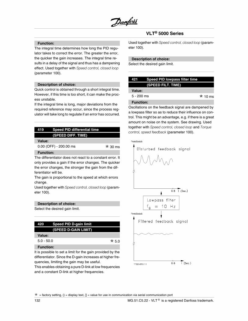
Function:The integral time determines how long the PID regu-lator takes to correct the error. The greater the error,the quicker the gain increases. The integral time re-sults in a delay of the signal and thus has a dampeningeffect. Used together with Speed control, closed loop(parameter 100).
Description of choice:Quick control is obtained through a short integral time.However, if this time is too short, it can make the proc-ess unstable.If the integral time is long, major deviations from therequired reference may occur, since the process reg-ulator will take long to regulate if an error has occurred.
419 Speed PID differential time
(SPEED DIFF. TIME)
Value:0.00 (OFF) - 200.00 ms 30 ms
Function:The differentiator does not react to a constant error. Itonly provides a gain if the error changes. The quickerthe error changes, the stronger the gain from the dif-ferentiator will be.The gain is proportional to the speed at which errorschange.Used together with Speed control, closed loop (param-eter 100).
Description of choice:Select the desired gain limit.
420 Speed PID D-gain limit
(SPEED D-GAIN LIMIT)
Value:5.0 - 50.0 5.0
Function:It is possible to set a limit for the gain provided by thedifferentiator. Since the D-gain increases at higher fre-quencies, limiting the gain may be useful.This enables obtaining a pure D-link at low frequenciesand a constant D-link at higher frequencies.
Used together with Speed control, closed loop (param-eter 100).
Description of choice:Select the desired gain limit.
421 Speed PID lowpass filter time
(SPEED FILT. TIME)
Value:5 - 200 ms 10 ms
Function:Oscillations on the feedback signal are dampened bya lowpass filter so as to reduce their influence on con-trol. This might be an advantage, e.g. if there is a greatamount on noise on the system. See drawing. Usedtogether with Speed control, closed loop and Torquecontrol, speed feedback (parameter 100).
VLT® 5000 Series
= factory setting, () = display text, [] = value for use in communication via serial communication port
132 MG.51.C5.22 - VLT is a registered Danfoss trademark.
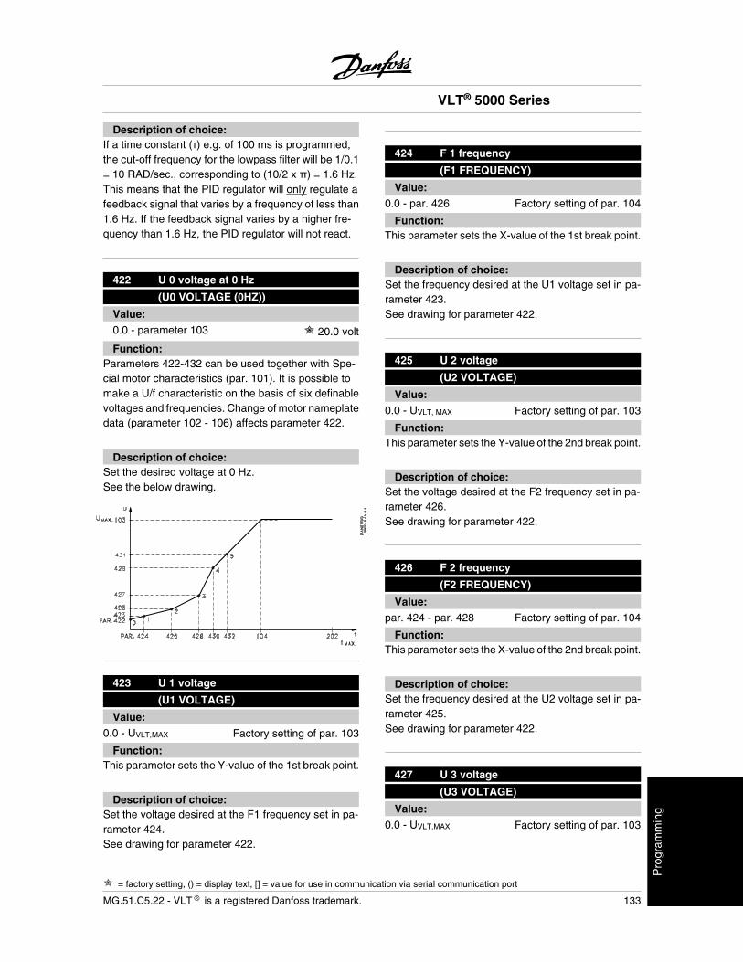
Description of choice:If a time constant ( ) e.g. of 100 ms is programmed,the cut-off frequency for the lowpass filter will be 1/0.1= 10 RAD/sec., corresponding to (10/2 x ) = 1.6 Hz.This means that the PID regulator will only regulate afeedback signal that varies by a frequency of less than1.6 Hz. If the feedback signal varies by a higher fre-quency than 1.6 Hz, the PID regulator will not react.
422 U 0 voltage at 0 Hz
(U0 VOLTAGE (0HZ))
Value:0.0 - parameter 103 20.0 volt
Function:Parameters 422-432 can be used together with Spe-cial motor characteristics (par. 101). It is possible tomake a U/f characteristic on the basis of six definablevoltages and frequencies. Change of motor nameplatedata (parameter 102 - 106) affects parameter 422.
Description of choice:Set the desired voltage at 0 Hz.See the below drawing.
423 U 1 voltage
(U1 VOLTAGE)
Value:0.0 - UVLT,MAX Factory setting of par. 103
Function:This parameter sets the Y-value of the 1st break point.
Description of choice:Set the voltage desired at the F1 frequency set in pa-rameter 424.See drawing for parameter 422.
424 F 1 frequency
(F1 FREQUENCY)
Value:0.0 - par. 426 Factory setting of par. 104
Function:This parameter sets the X-value of the 1st break point.
Description of choice:Set the frequency desired at the U1 voltage set in pa-rameter 423.See drawing for parameter 422.
425 U 2 voltage
(U2 VOLTAGE)
Value:0.0 - UVLT, MAX Factory setting of par. 103
Function:This parameter sets the Y-value of the 2nd break point.
Description of choice:Set the voltage desired at the F2 frequency set in pa-rameter 426.See drawing for parameter 422.
426 F 2 frequency
(F2 FREQUENCY)
Value:par. 424 - par. 428 Factory setting of par. 104
Function:This parameter sets the X-value of the 2nd break point.
Description of choice:Set the frequency desired at the U2 voltage set in pa-rameter 425.See drawing for parameter 422.
427 U 3 voltage
(U3 VOLTAGE)
Value:0.0 - UVLT,MAX Factory setting of par. 103
VLT® 5000 Series
= factory setting, () = display text, [] = value for use in communication via serial communication port
MG.51.C5.22 - VLT is a registered Danfoss trademark. 133
Pro
gram
min
g
Function:This parameter sets the Y-value of the 3rd break point.
Description of choice:Set the voltage desired at the F3 frequency set in pa-rameter 428.See drawing for parameter 422.
428 F 3 frequency
(F3 FREQUENCY)
Value:par. 426 - par. 430 Factory setting of par. 104
Function:This parameter sets the X-value of the 3rd break point.
Description of choice:Set the frequency desired at the U3 voltage set in pa-rameter 427.See drawing for parameter 422.
429 U 4 voltage
(U4 VOLTAGE)
Value:0.0 - UVLT,MAX Factory setting of par. 103
Function:This parameter sets the Y-value of the 4th break point.
Description of choice:Set the voltage desired at the F4 frequency set in pa-rameter 430.See drawing for parameter 422.
430 F 4 frequency
(F4 FREQUENCY)
Value:par. 428 - par. 432 Factory setting of par. 104
Function:This parameter sets the X-value of the 4th break point
Description of choice:Set the frequency desired at the U4 voltage set in pa-rameter 429.See drawing for parameter 422.
431 U 5 voltage
(U5 VOLTAGE)
Value:0.0 - UVLT, MAX Factory setting of par. 103
Function:This parameter sets the Y-value of the 5th break point.
Description of choice:Set the voltage desired at the F5 frequency set in pa-rameter 432.
432 F 5 frequency
(F5 FREQUENCY)
Value:par. 430 - 1000 Hz Factory setting of par. 104
Function:This parameter sets the X-value of the 5th break point.This parameter is not limited by parameter 200.
Description of choice:Set the frequency desired at the U5 voltage set in pa-rameter 431.See drawing for parameter 422.
433Torque control, open loop proportionalgain
(TOR-OL PROP. GAIN)
Value:0 (Off) - 500% 100%
Function:The proportional gain indicates how many times theerror (the deviation between feedback signal and setpoint) is to be applied.Used together with Torque control, open loop (param-eter 100).
Description of choice:Fast control is obtained with a high gain, but if the gainis too high, the process may become unstable.
VLT® 5000 Series
= factory setting, () = display text, [] = value for use in communication via serial communication port
134 MG.51.C5.22 - VLT is a registered Danfoss trademark.
434Torque control, open loop Integrationtime
(TOR-OL INT.TIME)
Value:0.002 - 2.000 sec. 0.02 sec.
Function:The integrator provides an increasing gain if there is aconstant error between reference and current meas-uring signal. The greater the error, the quicker the gainincreases. The integral time is the time required by theintegrator to reach the same gain as the proportionalgain.Used together with Torque control, open loop (param-eter 100).
Description of choice:Fast control is obtained if the integral time is short.However, this time may become too short, in whichcase the process may become unstable.
437 Process PID Normal/inverse control
(PROC NO/INV CTRL)
Value:
Normal (NORMAL) [0]
Inverse (INVERSE) [1]
Function:It is possible to choose whether the process regulatoris to increase/reduce the output frequency. This isdone by having a difference between the referencesignal and the feedback signal.Used together with Process control, closed-loop (pa-rameter 100).
Description of choice:If the adjustable frequency drive is to reduce the outputfrequency in case the feedback signal increases, se-lect Normal [0].If the adjustable frequency drive is to increase the out-put frequency in case the feedback signal increases,select Inverse [1].
438 Process PID anti windup
(PROC ANTI WINDUP)
Value:
Off (DISABLE) [0]
On (ENABLE) [1]
Function:It is possible to select whether the process regulator isto continue regulating on an error even if it is not pos-sible to increase/reduce the output frequency.Used together with Process control, closed loop (pa-rameter 100).
Description of choice:The factory setting is Enable [1], which means that theintegration link is adjusted in relation to the actual out-put frequency if either the current limit or the max./min.frequency has been reached. The process regulatorwill not engage again until either the error is zero or itssign has changed.Select Disable [0] if the integrator is to continue inte-grating on an error, even if it is not possible to removethe fault by such control.
NOTEIf Disable [0] is selected, it will mean thatwhen the error changes its sign, the inte-grator will first have to integrate down fromthe level obtained as a result of the formererror, before any change to the output fre-quency occurs.
439 Process PID start frequency
(PROC START VALUE)
Value:fMIN -fMAX (parameter 201 and202) parameter 201
Function:When the start signal comes, the adjustable frequencydrive will react in the form of Speed control, openloop following the ramp. Only when the programmedstart frequency has been obtained, will it change overto Process control, closed loop . In addition, it is pos-sible to set a frequency that corresponds to the speed
VLT® 5000 Series
= factory setting, () = display text, [] = value for use in communication via serial communication port
MG.51.C5.22 - VLT is a registered Danfoss trademark. 135
Pro
gram
min
g
at which the process normally runs, which will enablethe required process conditions to be reached sooner.Used together with Process control, closed loop (pa-rameter 100).
Description of choice:Set the required start frequency.
NOTEIf the adjustable frequency drive is runningat the current limit before the desired startfrequency is obtained, the process regu-lator will not be activated. For the regulatorto be activated anyway, the start frequen-cy must be lowered to the required outputfrequency. This can be done during oper-ation.
440 Process PID proportional gain
(PROC. PROP. GAIN)
Value:0.00 - 10.00 0.01
Function:The proportional gain indicates the number of timesthe error between the set point and the feedback signalis to be applied.Used together with Process control, closed loop (pa-rameter 100).
Description of choice:Quick control is obtained by a high gain, but if the gainis too high, the process may become unstable.
441 Process PID integral time
(PROC. INTEGR. T.)
Value:0.01 - 9999.99 sec. (OFF) OFF
Function:The integrator provides an increasing gain at a con-stant error between the set point and the feedbacksignal. The greater the error, the quicker the gain willincrease. The integral time is the time needed by the
integrator to reach the same gain as the proportionalgain.The gain is proportional to the speed at which the errorchanges.Used together with Process control, closed loop (pa-rameter 100).
Description of choice:Quick control is obtained at a short integral time. How-ever, this time may become too short, which can makethe process unstable.If the integral time is long, major deviations from therequired set point may occur, since the process regu-lator will take a long time to regulate in relation to agiven error.
442 Process PID differentiation time
(PROC. DIFF. TIME)
Value:0.00 (OFF) - 10.00 sec. 0.00 sec.
Function:The differentiator does not react to a constant error. Itonly provides a gain when the error changes. Thequicker the error changes, the stronger the gain fromthe differentiator.The gain is proportional to the speed at which the errorchanges.Used together with Process control, closed loop (pa-rameter 100).
Description of choice:Quick control is obtained with a long differentiationtime. However, this time may become too long, whichcan make the process unstable.
443 Process PID diff. gain limit
(PROC. DIFF. GAIN)
Value:5.0 - 50.0 5.0
Function:It is possible to set a limit for the differentiator gain. Thedifferentiator gain will increase if there are fastchanges, which is why it can be beneficial to limit thisgain, thereby obtaining a pure differentiator gain at
VLT® 5000 Series
= factory setting, () = display text, [] = value for use in communication via serial communication port
136 MG.51.C5.22 - VLT is a registered Danfoss trademark.
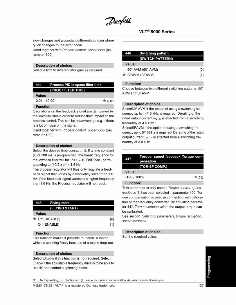
slow changes and a constant differentiator gain wherequick changes to the error occur.Used together with Process control, closed loop (pa-rameter 100).
Description of choice:Select a limit to differentiator gain as required.
444 Process PID lowpass filter time
(PROC FILTER TIME)
Value:0.01 - 10.00 0.01
Function:Oscillations on the feedback signal are dampened bythe lowpass filter in order to reduce their impact on theprocess control. This can be an advantage e.g. if thereis a lot of noise on the signal.Used together with Process control, closed loop (pa-rameter 100).
Description of choice:Select the desired time constant ( ). If a time constant( ) of 100 ms is programmed, the break frequency forthe lowpass filter will be 1/0.1 = 10 RAD/sec., corre-sponding to (10/2 x ) = 1.6 Hz.The process regulator will thus only regulate a feed-back signal that varies by a frequency lower than 1.6Hz. If the feedback signal varies by a higher frequencythan 1.6 Hz, the Process regulator will not react.
445 Flying start
(FLYING START)
Value:
Off (DISABLE) [0]
On (ENABLE) [1]
Function:This function makes it possible to `catch` a motor,which is spinning freely because of a mains drop-out.
Description of choice:Select Disable if this function is not required. SelectEnable if the adjustable frequency drive is to be able to`catch' and control a spinning motor.
446 Switching pattern
(SWITCH PATTERN)
Value:
60° AVM (60° AVM) [0]
SFAVM (SFAVM) [1]
Function:Choose between two different switching patterns: 60°AVM and SFAVM.
Description of choice:Select60° AVM if the option of using a switching fre-quency up to 14/10 kHz is required. Derating of therated output current IVLT.N is effected from a switchingfrequency of 4.5 kHz.SelectSFAVM if the option of using a switching fre-quency up to 5/10 kHz is required. Derating of the ratedoutput current IVLT.N is effected from a switching fre-quency of 3.0 kHz.
447Torque, speed feedback Torque com-pensation
(TOR-SF COMP.)
Value:-100 - 100% 0%
Function:This parameter is only used if Torque control, speedfeedback [5] has been selected in parameter 100. Tor-que compensation is used in connection with calibra-tion of the frequency converter. By adjusting parame-ter 447, Torque compensation, the output torque canbe calibrated.See section Setting of parameters, torque regulation,speed feedback.
Description of choice:Set the required value.
VLT® 5000 Series
= factory setting, () = display text, [] = value for use in communication via serial communication port
MG.51.C5.22 - VLT is a registered Danfoss trademark. 137
Pro
gram
min
g
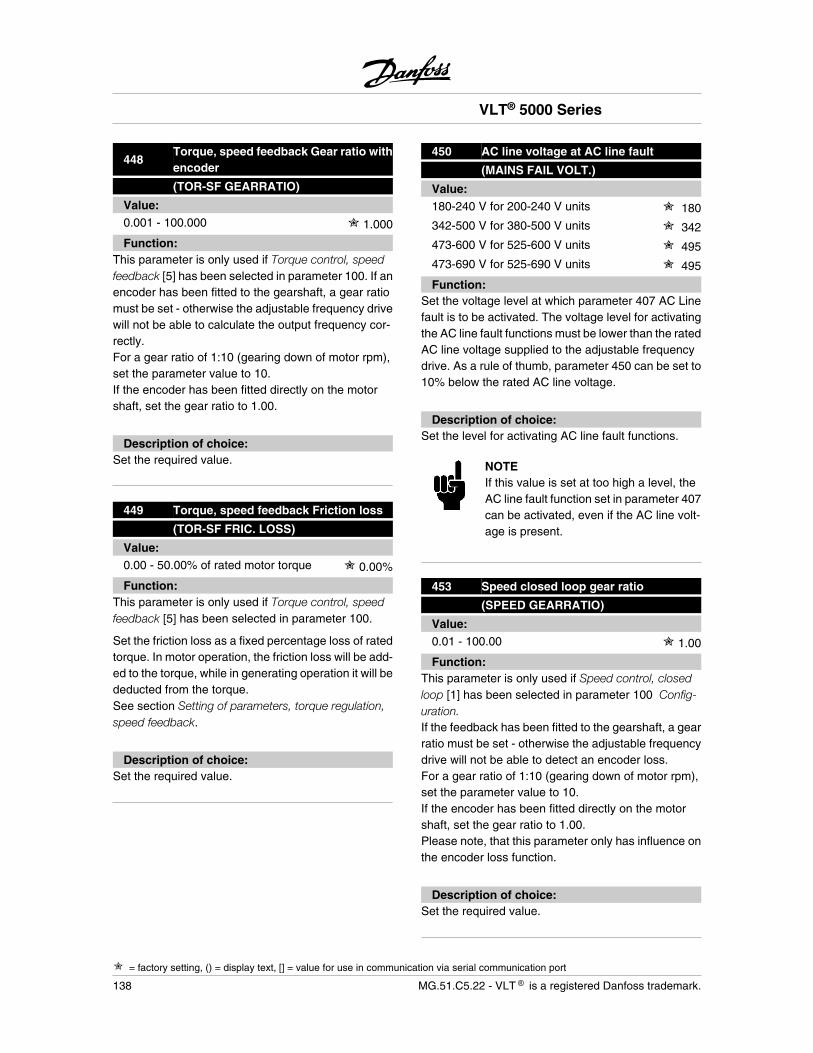
448Torque, speed feedback Gear ratio withencoder
(TOR-SF GEARRATIO)
Value:0.001 - 100.000 1.000
Function:This parameter is only used if Torque control, speedfeedback [5] has been selected in parameter 100. If anencoder has been fitted to the gearshaft, a gear ratiomust be set - otherwise the adjustable frequency drivewill not be able to calculate the output frequency cor-rectly.For a gear ratio of 1:10 (gearing down of motor rpm),set the parameter value to 10.If the encoder has been fitted directly on the motorshaft, set the gear ratio to 1.00.
Description of choice:Set the required value.
449 Torque, speed feedback Friction loss
(TOR-SF FRIC. LOSS)
Value:0.00 - 50.00% of rated motor torque 0.00%
Function:This parameter is only used if Torque control, speedfeedback [5] has been selected in parameter 100.
Set the friction loss as a fixed percentage loss of ratedtorque. In motor operation, the friction loss will be add-ed to the torque, while in generating operation it will bededucted from the torque.See section Setting of parameters, torque regulation,speed feedback.
Description of choice:Set the required value.
450 AC line voltage at AC line fault
(MAINS FAIL VOLT.)
Value:180-240 V for 200-240 V units 180
342-500 V for 380-500 V units 342
473-600 V for 525-600 V units 495
473-690 V for 525-690 V units 495
Function:Set the voltage level at which parameter 407 AC Linefault is to be activated. The voltage level for activatingthe AC line fault functions must be lower than the ratedAC line voltage supplied to the adjustable frequencydrive. As a rule of thumb, parameter 450 can be set to10% below the rated AC line voltage.
Description of choice:Set the level for activating AC line fault functions.
NOTEIf this value is set at too high a level, theAC line fault function set in parameter 407can be activated, even if the AC line volt-age is present.
453 Speed closed loop gear ratio
(SPEED GEARRATIO)
Value:0.01 - 100.00 1.00
Function:This parameter is only used if Speed control, closedloop [1] has been selected in parameter 100 Config-uration.If the feedback has been fitted to the gearshaft, a gearratio must be set - otherwise the adjustable frequencydrive will not be able to detect an encoder loss.For a gear ratio of 1:10 (gearing down of motor rpm),set the parameter value to 10.If the encoder has been fitted directly on the motorshaft, set the gear ratio to 1.00.Please note, that this parameter only has influence onthe encoder loss function.
Description of choice:Set the required value.
VLT® 5000 Series
= factory setting, () = display text, [] = value for use in communication via serial communication port
138 MG.51.C5.22 - VLT is a registered Danfoss trademark.
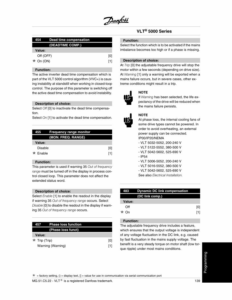
454 Dead time compensation
(DEADTIME COMP.)
Value:
Off (OFF) [0]
On (ON) [1]
Function:The active inverter dead time compensation which ispart of the VLT 5000 control algorithm (VVC+) is caus-ing instability at standstill when working in closed-loopcontrol. The purpose of this parameter is switching offthe active dead time compensation to avoid instability.
Description of choice:Select Off [0] to inactivate the dead time compensa-tion.Select On [1] to activate the dead time compensation.
455 Frequency range monitor
(MON. FREQ. RANGE)
Value:
Disable [0]
Enable [1]
Function:This parameter is used if warning 35 Out of frequencyrange must be turned off in the display in process con-trol closed loop. This parameter does not affect theextended status word.
Description of choice:Select Enable [1] to enable the readout in the displayif warning 35 Out of frequency range occurs. SelectDisable [0] to disable the readout in the display if warn-ing 35 Out of frequency range occurs.
457 Phase loss function
(Phase loss funct)
Value:
Trip (Trip) [0]
Warning (Warning) [1]
Function:Select the function which is to be activated if the mainsimbalance becomes too high or if a phase is missing.
Description of choice:At Trip [0] the adjustable frequency drive will stop themotor within a few seconds (depending on drive size).At Warning [1] only a warning will be exported when amains failure occurs, but in severe cases, other ex-treme conditions might result in a trip.
NOTEIf Warning has been selected, the life ex-pectancy of the drive will be reduced whenthe mains failure persists.
NOTEAt phase loss, the internal cooling fans ofsome drive types cannot be powered. Inorder to avoid overheating, an externalpower supply can be connected.IP00/IP20/NEMA- VLT 5032-5052, 200-240 V- VLT 5122-5552, 380-500 V- VLT 5042-5602, 525-690 V- IP54- VLT 5006-5052, 200-240 V- VLT 5016-5552, 380-500 V- VLT 5042-5602, 525-690 VSee also Electrical Installation.
483 Dynamic DC link compensation
(DC link comp.)
Value:
Off [0]
On [1]
Function:The adjustable frequency drive includes a feature,which ensures that the output voltage is independentof any voltage fluctuation in the DC link, e.g. causedby fast fluctuation in the mains supply voltage. Thebenefit is a very steady torque on motor shaft (low tor-que ripple) under most mains conditions.
VLT® 5000 Series
= factory setting, () = display text, [] = value for use in communication via serial communication port
MG.51.C5.22 - VLT is a registered Danfoss trademark. 139
Pro
gram
min
g
Description of choice:In some cases this dynamic compensation can causeresonance’s in the DC link and should then be disa-bled. Typical cases are where a line choke or a passiveharmonic filter (e.g. filters AHF005/010) is mounted inthe mains supply to the frequency converter to sup-press harmonics. Can also occur on mains with lowshort circuit ratio.
VLT® 5000 Series
140 MG.51.C5.22 - VLT is a registered Danfoss trademark.
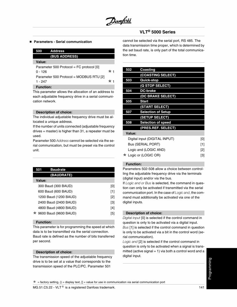
Parameters - Serial communication
500 Address
(BUS ADDRESS)
Value:Parameter 500 Protocol = FC protocol [0]0 - 126 1
Parameter 500 Protocol = MODBUS RTU [2]1 - 247 1
Function:This parameter allows the allocation of an address toeach adjustable frequency drive in a serial communi-cation network.
Description of choice:The individual adjustable frequency drive must be al-located a unique address.If the number of units connected (adjustable frequencydrives + master) is higher than 31, a repeater must beused.Parameter 500 Address cannot be selected via the se-rial communication, but must be preset via the controlunit.
501 Baudrate
(BAUDRATE)
Value:
300 Baud (300 BAUD) [0]
600 Baud (600 BAUD) [1]
1200 Baud (1200 BAUD) [2]
2400 Baud (2400 BAUD) [3]
4800 Baud (4800 BAUD) [4]
9600 Baud (9600 BAUD) [5]
Function:This parameter is for programming the speed at whichdata is to be transmitted via the serial connection.Baud rate is defined as the number of bits transferredper second.
Description of choice:The transmission speed of the adjustable frequencydrive is to be set at a value that corresponds to thetransmission speed of the PLC/PC. Parameter 501
cannot be selected via the serial port, RS 485. Thedata transmission time proper, which is determined bythe set baud rate, is only part of the total communica-tion time.
502 Coasting
(COASTING SELECT)503 Quick-stop
(Q STOP SELECT)504 DC-brake
(DC BRAKE SELECT)505 Start
(START SELECT)507 Selection of Setup
(SETUP SELECT)508 Selection of speed
(PRES.REF. SELECT)
Value:
Digital input (DIGITAL INPUT) [0]
Bus (SERIAL PORT) [1]
Logic and (LOGIC AND) [2]
Logic or (LOGIC OR) [3]
Function:Parameters 502-508 allow a choice between control-ling the adjustable frequency drive via the terminals(digital input) and/or via the bus.If Logic and or Bus is selected, the command in ques-tion can only be activated if transmitted via the serialcommunication port. In the case of Logic and, the com-mand must additionally be activated via one of thedigital inputs.
Description of choice:Digital input [0] is selected if the control command inquestion is only to be activated via a digital input.Bus [1] is selected if the control command in questionis only to be activated via a bit in the control word (se-rial communication).Logic and [2] is selected if the control command inquestion is only to be activated when a signal is trans-mitted (active signal = 1) via both a control word and adigital input.
VLT® 5000 Series
= factory setting, () = display text, [] = value for use in communication via serial communication port
MG.51.C5.22 - VLT is a registered Danfoss trademark. 141
Pro
gram
min
g
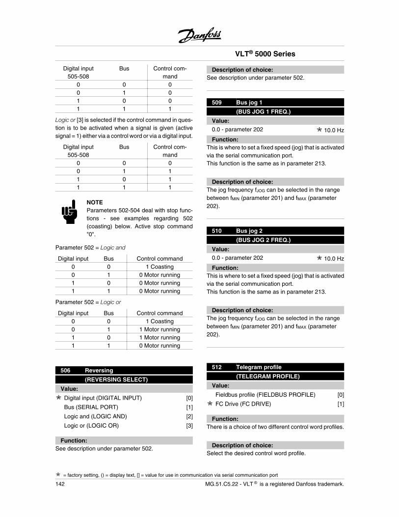
Digital input505-508
Bus Control com-mand
0 0 00 1 01 0 01 1 1
Logic or [3] is selected if the control command in ques-tion is to be activated when a signal is given (activesignal = 1) either via a control word or via a digital input.
Digital input505-508
Bus Control com-mand
0 0 00 1 11 0 11 1 1
NOTEParameters 502-504 deal with stop func-tions - see examples regarding 502(coasting) below. Active stop command"0".
Parameter 502 = Logic and
Digital input Bus Control command0 0 1 Coasting0 1 0 Motor running1 0 0 Motor running1 1 0 Motor running
Parameter 502 = Logic or
Digital input Bus Control command0 0 1 Coasting0 1 1 Motor running1 0 1 Motor running1 1 0 Motor running
506 Reversing
(REVERSING SELECT)
Value:
Digital input (DIGITAL INPUT) [0]
Bus (SERIAL PORT) [1]
Logic and (LOGIC AND) [2]
Logic or (LOGIC OR) [3]
Function:See description under parameter 502.
Description of choice:See description under parameter 502.
509 Bus jog 1
(BUS JOG 1 FREQ.)
Value:0.0 - parameter 202 10.0 Hz
Function:This is where to set a fixed speed (jog) that is activatedvia the serial communication port.This function is the same as in parameter 213.
Description of choice:The jog frequency fJOG can be selected in the rangebetween fMIN (parameter 201) and fMAX (parameter202).
510 Bus jog 2
(BUS JOG 2 FREQ.)
Value:0.0 - parameter 202 10.0 Hz
Function:This is where to set a fixed speed (jog) that is activatedvia the serial communication port.This function is the same as in parameter 213.
Description of choice:The jog frequency fJOG can be selected in the rangebetween fMIN (parameter 201) and fMAX (parameter202).
512 Telegram profile
(TELEGRAM PROFILE)
Value:
Fieldbus profile (FIELDBUS PROFILE) [0]
FC Drive (FC DRIVE) [1]
Function:There is a choice of two different control word profiles.
Description of choice:Select the desired control word profile.
VLT® 5000 Series
= factory setting, () = display text, [] = value for use in communication via serial communication port
142 MG.51.C5.22 - VLT is a registered Danfoss trademark.
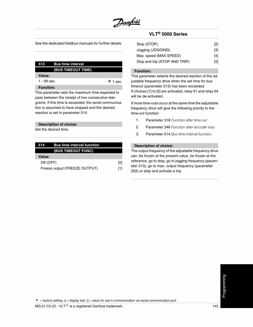
See the dedicated fieldbus manuals for further details.
513 Bus time interval
(BUS TIMEOUT TIME)
Value:1 - 99 sec. 1 sec.
Function:This parameter sets the maximum time expected topass between the receipt of two consecutive tele-grams. If this time is exceeded, the serial communica-tion is assumed to have stopped and the desiredreaction is set in parameter 514.
Description of choice:Set the desired time.
514 Bus time interval function
(BUS TIMEOUT FUNC)
Value:
Off (OFF) [0]
Freeze output (FREEZE OUTPUT) [1]
Stop (STOP) [2]
Jogging (JOGGING) [3]
Max. speed (MAX SPEED) [4]
Stop and trip (STOP AND TRIP) [5]
Function:This parameter selects the desired reaction of the ad-justable frequency drive when the set time for bustimeout (parameter 513) has been exceeded.If choices [1] to [5] are activated, relay 01 and relay 04will be de-activated.
If more time-outs occur at the same time the adjustablefrequency drive will give the following priority to thetime-out function:
1. Parameter 318 Function after time out
2. Parameter 346 Function after encoder loss
3. Parameter 514 Bus time interval function.
Description of choice:The output frequency of the adjustable frequency drivecan: be frozen at the present value, be frozen at thereference, go to stop, go to jogging frequency (param-eter 213), go to max. output frequency (parameter202) or stop and activate a trip.
VLT® 5000 Series
= factory setting, () = display text, [] = value for use in communication via serial communication port
MG.51.C5.22 - VLT is a registered Danfoss trademark. 143
Pro
gram
min
g
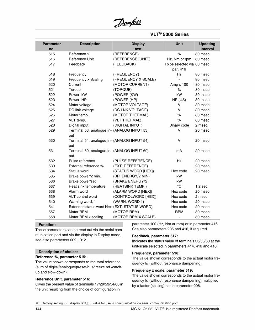
Parameterno.
Description Displaytext
Unit Updatinginterval
515 Reference % (REFERENCE) % 80 msec.516 Reference Unit (REFERENCE [UNIT]) Hz, Nm or rpm 80 msec.517 Feedback (FEEDBACK) To be selected via
par. 41680 msec.
518 Frequency (FREQUENCY) Hz 80 msec.519 Frequency x Scaling (FREQUENCY X SCALE) - 80 msec.520 Current (MOTOR CURRENT) Amp x 100 80 msec.521 Torque (TORQUE) % 80 msec.522 Power, kW (POWER (KW) kW 80 msec.523 Power, HP (POWER (HP) HP (US) 80 msec.524 Motor voltage (MOTOR VOLTAGE) V 80 msec.525 DC link voltage (DC LNK VOLTAGE) V 80 msec.526 Motor temp. (MOTOR THERMAL) % 80 msec.527 VLT temp. (VLT THERMAL) % 80 msec.528 Digital input (DIGITAL INPUT) Binary code 2 msec.529 Terminal 53, analogue in-
put(ANALOG INPUT 53) V 20 msec.
530 Terminal 54, analogue in-put
(ANALOG INPUT 54) V 20 msec.
531 Terminal 60, analogue in-put
(ANALOG INPUT 60) mA 20 msec.
532 Pulse reference (PULSE REFERENCE) Hz 20 msec.533 External reference % (EXT. REFERENCE) 20 msec.534 Status word (STATUS WORD [HEX]) Hex code 20 msec.535 Brake power/2 min. (BR. ENERGY/2 MIN) kW 536 Brake power/sec. (BRAKE ENERGY/S) kW 537 Heat sink temperature (HEATSINK TEMP.) °C 1.2 sec.538 Alarm word (ALARM WORD [HEX]) Hex code 20 msec.539 VLT control word (CONTROLWORD [HEX]) Hex code 2 msec.540 Warning word, 1 (WARN. WORD 1) Hex code 20 msec.541 Extended status word Hex (EXT. STATUS WORD) Hex code 20 msec.557 Motor RPM (MOTOR RPM) RPM 80 msec.558 Motor RPM x scaling (MOTOR RPM X SCALE) - 80 msec.
Function:These parameters can be read out via the serial com-munication port and via the display in Display mode,see also parameters 009 - 012.
Description of choice:Reference %, parameter 515:The value shown corresponds to rhe total reference(sum of digital/analogue/preset/bus/freeze ref./catch-up and slow-down).
Reference Unit, parameter 516:Gives the present value of terminals 17/29/53/54/60 inthe unit resulting from the choice of configuration in
parameter 100 (Hz, Nm or rpm) or in parameter 416.See also parameters 205 and 416, if required.
Feedback, parameter 517:Indicates the status value of terminals 33/53/60 at theunit/scale selected in parameters 414, 416 and 416.
Frequency, parameter 518:The value shown corresponds to the actual motor fre-quency fM (without resonance dampening).
Frequency x scale, parameter 519:The value shown corresponds to the actual motor fre-quency fM (without resonance dampening) multipliedby a factor (scaling) set in parameter 008.
VLT® 5000 Series
= factory setting, () = display text, [] = value for use in communication via serial communication port
144 MG.51.C5.22 - VLT is a registered Danfoss trademark.
Motor current, parameter 520:The value shown corresponds to the given motor cur-rent measured as a mean value IRMS.The value is filtered, which means that approx. 1.3seconds may pass from an input value changes untilthe data read-out changes values.
Torque, parameter 521:The value shown is the torque, with sign, supplied tothe motor shaft. The value is given as a percentage ofthe rated torque.There is not exact linearity between 160% motor cur-rent and torque in relation to the rated torque. Somemotors supply more torque than that. Consequently,the min. value and the max. value will depend on themax. motor current as well as the motor used.The value is filtered, which means that approx. 1.3seconds may pass from an input changes value untilthe data read-out changes values.
NOTEIf the setting of the motor parameters doesnot match the motor applied, the read-outvalues will be inaccurate and may becomenegative, even if the motor is not runningor is producing a positive torque.
Power, (kW), parameter 522:The value shown is calculated on the basis of the ac-tual motor voltage and motor current.The value is filtered, which means that it may take ap-prox. 1.3 seconds from an input value changes untilthe data read-out changes values.
Power (HP), parameter 523:The value shown is calculated on the basis of the ac-tual motor voltage and motor current.The value is indicated in the form of HP.The value is filtered, which means that approx. 1.3seconds may pass from an input value changes untilthe data read-out changes values.
Motor voltage, parameter 524:The value shown is a calculated value used for con-trolling the motor.
DC link voltage, parameter 525:The value shown is a measured value.The value is filtered, which means that approx. 1.3seconds may pass from an input value changes untilthe data read-out changes values.
Motor temp., parameter 526:
VLT temp., parameter 527:Only whole numbers are displayed.
Digital input, parameter 528:The value shown indicates the signal status from the8 digital terminals (16, 17, 18, 19, 27, 29, 32 and 33).The read-out is binary and the digit at the extreme leftgives the status of terminal 16, while the digit at theextreme right gives the status of terminal 33.
Terminal 53, analogue input, parameter 529:The value shown indicates the signal value on terminal53.The scaling (parameters 309 and 310) does not influ-ence the read-out. Min. and max. are determined bythe offset and gain adjustment of the AD-converter.
Terminal 54, analogue input, parameter 530:The value shown indicates the signal value on terminal54.The scaling (parameters 312 and 313) does not influ-ence the read-out. Min. and max. are determined bythe offset and gain adjustment of the AD-converter.
Terminal 60, analogue input, parameter 531:The value shown indicates the signal value on terminal60.The scaling (parameters 315 and 316) does not influ-ence the read-out. Min. and max. are determined bythe offset and gain adjustment of the AD-converter.
Pulse reference, parameter 532:The value shown indicates any pulse reference in Hzconnected to one of the digital inputs.
External reference %, parameter 533:The value stated gives, as a percentage, the sum ofexternal references (sum of analogue/bus/pulse).
Status word, parameter 534:Indicates the status word transmitted via the serialcommunication port in Hex code from the frequencyconverter. See the Design Guide.
Brake power/2min., parameter 535:
Indicates the brake power transmitted to an externalbrake resistor. The mean power is calculated on anongoing basis for the latest 120 sec.
Brake power/sec., parameter 536:Indicates the given brake power transmitted to an ex-ternal brake resistor. Stated as an instantaneous val-ue.
VLT® 5000 Series
= factory setting, () = display text, [] = value for use in communication via serial communication port
MG.51.C5.22 - VLT is a registered Danfoss trademark. 145
Pro
gram
min
g
Heat sink temperature, parameter 537:States the given heat sink temperature of the frequen-cy converter. The cut-out limit is 90 ± 5°C, while theunit cuts back in at 60 ± 5°C.
Alarm word, parameter 538:States in Hex format whether there is an alarm on thefrequency converter.See section Warning word 1, Ex-tended status word and Alarm word for further informa-tion.
VLT control word, parameter 539:Gives the control word sent via the serial communica-tion port in Hex code to the frequency converter. Seethe Design Guide for further information.
Warning word, 1, parameter 540:States in Hex format whether there is a warning on thefrequency converter. See section Warning word 1, Ex-tended status word and Alarm word for further informa-tion.
Extended status word Hex, parameter 541:States in Hex format whether there is a warning on thefrequency converter.
See section Warning word 1, Extended status word andAlarm word for further information.
Motor RPM, parameter 557:The displayed value corresponds to the actual motorRPM. In open loop or closed loop process control, themotor RPM is estimated. In speed closed loop modes,it is measured.
Motor RPM x scaling, parameter 558:The displayed value corresponds to the actual motorRPM multiplied by a factor (scaling) set in parameter008.
561 Protocol
(PROTOCOL)
Value:
FC protocol (FC PROTOKOL) [0]
Modbus RTU [3]
Function:There is a choice of two different protocols.
Description of choice:Select the required control word protocol.
For further information about using the Modbus RTU,see MG10SX.
570 Modbus parity and message framing
(M.BUS PAR./FRAME)
Value:
(EVEN/1 STOPBIT) [0]
(ODD/1 STOPBIT) [1]
(NO PARITY/1 STOPBIT) [2]
(NO PARITY/2 STOPBIT) [3]
Function:This parameter sets up the drive’s Modbus RTU inter-face to communicate properly with the master control-ler. The parity (EVEN, ODD, or NO PARITY) must beset to match the setting of the master controller.
Description of choice:Select the parity that matches the setting for the Mod-bus master controller. Even or odd parity is sometimesused to allow a transmitted word to be checked for er-rors. Because Modbus RTU uses the more efficientCRC (Cyclic Redundancy Check) method of checkingfor errors, parity checking is seldom used in ModbusRTU networks.
571 Modbus communications timeout
(M.BUS COM.TIME.)
Value:10 ms - 2000 ms 100 ms
Function:This parameter determines the maximum amount oftime that the drive’s Modbus RTU will wait betweencharacters that are sent by the master controller.When this amount of time expires, the drive’s ModbusRTU interface will assume that it has received the en-tire message.
Description of choice:Generally, the value of 100 ms is sufficient for ModbusRTU networks, although some Modbus RTU networksmay operate on a timeout value as short as 35 ms.If this value is set too short, the drive’s Modbus RTUinterface may miss a part of the message. Since theCRC check will not be valid, the drive will ignore the
VLT® 5000 Series
= factory setting, () = display text, [] = value for use in communication via serial communication port
146 MG.51.C5.22 - VLT is a registered Danfoss trademark.
message. The resulting retransmissions of messageswill slow communications on the network.If this value is set too long, the drive will wait longerthan necessary to determine that the message is com-pleted. This will delay the drive’s response to the mes-sage and possibly cause the master controller to timeout. The resulting retransmissions of messages willslow communications on the network.
VLT® 5000 Series
= factory setting, () = display text, [] = value for use in communication via serial communication port
MG.51.C5.22 - VLT is a registered Danfoss trademark. 147
Pro
gram
min
g
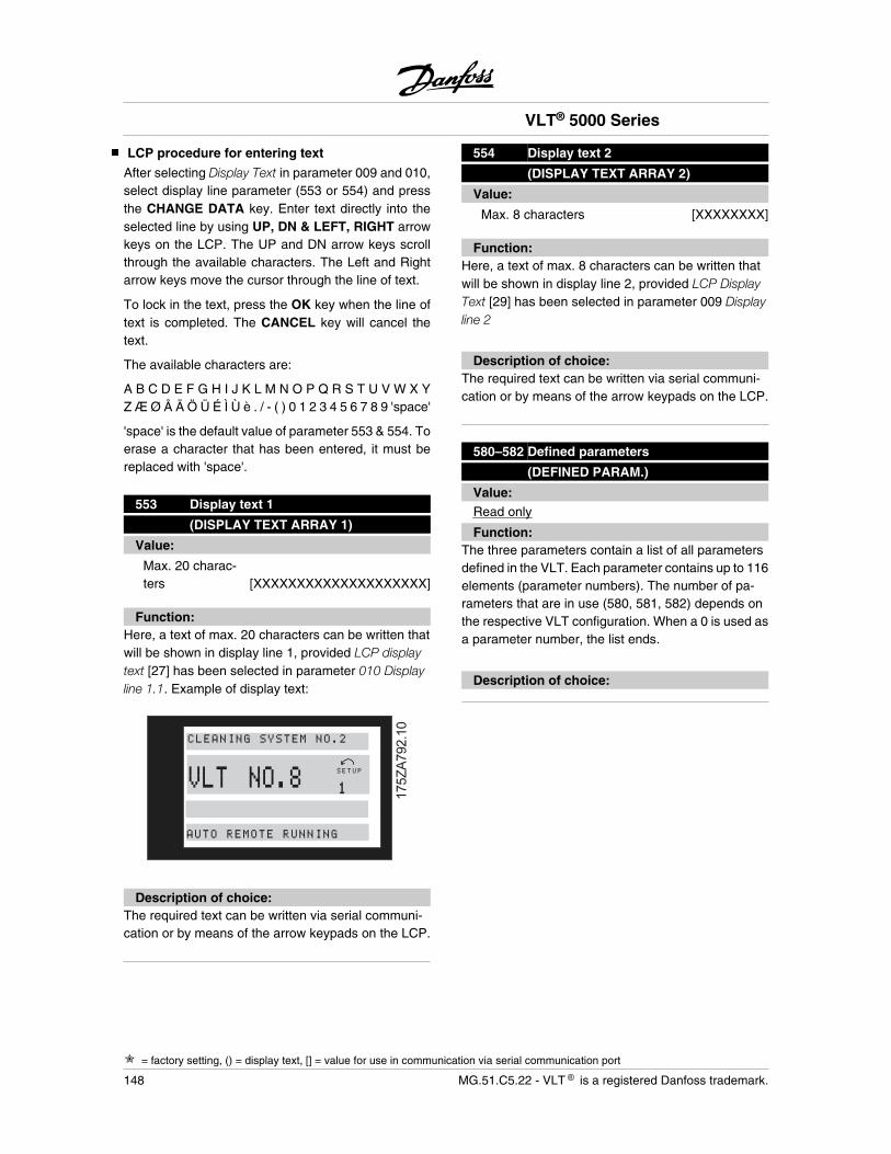
LCP procedure for entering text
After selecting Display Text in parameter 009 and 010,select display line parameter (553 or 554) and pressthe CHANGE DATA key. Enter text directly into theselected line by using UP, DN & LEFT, RIGHT arrowkeys on the LCP. The UP and DN arrow keys scrollthrough the available characters. The Left and Rightarrow keys move the cursor through the line of text.
To lock in the text, press the OK key when the line oftext is completed. The CANCEL key will cancel thetext.
The available characters are:
A B C D E F G H I J K L M N O P Q R S T U V W X YZ Æ Ø Å Ä Ö Ü É Ì Ù è . / - ( ) 0 1 2 3 4 5 6 7 8 9 'space'
'space' is the default value of parameter 553 & 554. Toerase a character that has been entered, it must bereplaced with 'space'.
553 Display text 1
(DISPLAY TEXT ARRAY 1)
Value:
Max. 20 charac-ters [XXXXXXXXXXXXXXXXXXXX]
Function:Here, a text of max. 20 characters can be written thatwill be shown in display line 1, provided LCP displaytext [27] has been selected in parameter 010 Displayline 1.1. Example of display text:
���������
VLT NO.8 SETUP
1
CLEANING SYSTEM NO.2
AUTO REMOTE RUNNING
Description of choice:The required text can be written via serial communi-cation or by means of the arrow keypads on the LCP.
554 Display text 2
(DISPLAY TEXT ARRAY 2)
Value:
Max. 8 characters [XXXXXXXX]
Function:Here, a text of max. 8 characters can be written thatwill be shown in display line 2, provided LCP DisplayText [29] has been selected in parameter 009 Displayline 2
Description of choice:The required text can be written via serial communi-cation or by means of the arrow keypads on the LCP.
580–582 Defined parameters
(DEFINED PARAM.)
Value:Read only
Function:The three parameters contain a list of all parametersdefined in the VLT. Each parameter contains up to 116elements (parameter numbers). The number of pa-rameters that are in use (580, 581, 582) depends onthe respective VLT configuration. When a 0 is used asa parameter number, the list ends.
Description of choice:
VLT® 5000 Series
= factory setting, () = display text, [] = value for use in communication via serial communication port
148 MG.51.C5.22 - VLT is a registered Danfoss trademark.

Parameters - Technical functions and diagnostics
Parameter no. DescriptionOperating data
Display text Unit Range
600 Operating hours (OPERATING HOURS) Hours 0 - 130,000.0601 Hours run (RUNNING HOURS) Hours 0 - 130,000.0602 kWh counter (KWH COUNTER) kWh 0 - 9999603 No. of cut-ins (POWER UP's) Nos. 0 - 9999604 No. of overtemps (OVER TEMP's) Nos. 0 - 9999605 No. of overvoltages (OVER VOLT'S) Nos. 0 - 9999
Function:These parameters can be read out via the serial com-munication port and via the display in the parameters.
Description of choice:Operating hours , parameter 600:Indicates the number of hours in which the adjustablefrequency drive has been in operation.The value is updated in the adjustable frequency driveevery hour and saved when the unit is turned off.
Hours run, parameter 601:Indicates the number of hours in which the adjustablefrequency drive has been in operation since reset inparameter 619.The value is updated in the adjustable frequency driveevery hour and saved when the unit is turned off.
kWh counter , parameter 602:States the kW consumption of the motor as a meanvalue over one hour, since the reset in parameter 618.
No. of cut-ins, parameter 603:States the number of power-ups of the supply voltageto the adjustable frequency drive.
No. of overtemps, parameter 604:States the number of temperature faults there hasbeen on the adjustable frequency drive.
No. of overvoltages, parameter 605:States the number of overvoltages there has been onthe adjustable frequency drive.
Parameter no. DescriptionData log
Display text Unit Range
606 Digital inputs (LOG: DIGITAL INP) Decimal 0 - 255607 Control word (LOG: CONTROL WORD Decimal 0 - 65535608 Status word (LOG: BUS STAT WD) Decimal 0 - 65535609 Reference (LOG: REFERENCE) % 0 - 100610 Feedback (LOG: FEEDBACK) Par. 416 999,999.99 -
999,999.99611 Output frequency (LOG: MOTOR FREQ.) Hz. 0.0 - 999.9612 Output voltage (LOG: MOTOR VOLT) Volt 50 - 1000613 Output current (LOG: MOTOR CURR.) Amp 0.0 - 999.9614 DC link voltage (LOG: DC LINK VOLT) Volt 0.0 - 999.9
Function:Via this parameter it is possible to see up to 20 data-logs, where [0] is the latest log and [19] the oldest.Each data-log is made every 160 ms as long as a startsignal has been given. If a stop signal is given, the lat-est 20 data-logs will be saved and the values will beavailable on the display. This is useful, e.g. when car-rying out service after a trip.
This parameter can be read out via the serial commu-nication port or via the display.
Description of choice:The data-log number is stated in square brackets: [1].Data-logs are frozen if there is a trip and releasedwhen the adjustable frequency drive is subsequentlyreset.Data-logging is active while the motor is running.
VLT® 5000 Series
= factory setting, () = display text, [] = value for use in communication via serial communication port
MG.51.C5.22 - VLT is a registered Danfoss trademark. 149
Pro
gram
min
g
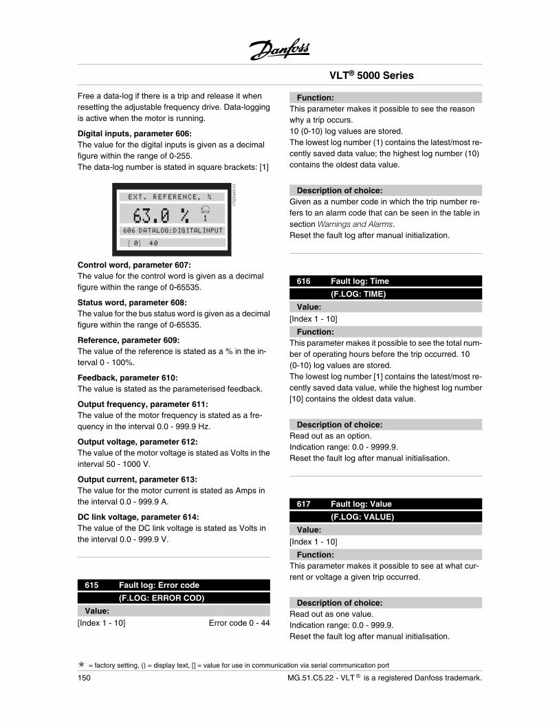
Free a data-log if there is a trip and release it whenresetting the adjustable frequency drive. Data-loggingis active when the motor is running.
Digital inputs, parameter 606:The value for the digital inputs is given as a decimalfigure within the range of 0-255.The data-log number is stated in square brackets: [1]
175Z
A449
.10
63.0 %EXT. REFERENCE, %
606 DATALOG:DIGITALINPUT
[0] 40
Control word, parameter 607:The value for the control word is given as a decimalfigure within the range of 0-65535.
Status word, parameter 608:The value for the bus status word is given as a decimalfigure within the range of 0-65535.
Reference, parameter 609:The value of the reference is stated as a % in the in-terval 0 - 100%.
Feedback, parameter 610:The value is stated as the parameterised feedback.
Output frequency, parameter 611:The value of the motor frequency is stated as a fre-quency in the interval 0.0 - 999.9 Hz.
Output voltage, parameter 612:The value of the motor voltage is stated as Volts in theinterval 50 - 1000 V.
Output current, parameter 613:The value for the motor current is stated as Amps inthe interval 0.0 - 999.9 A.
DC link voltage, parameter 614:The value of the DC link voltage is stated as Volts inthe interval 0.0 - 999.9 V.
615 Fault log: Error code
(F.LOG: ERROR COD)
Value:[Index 1 - 10] Error code 0 - 44
Function:This parameter makes it possible to see the reasonwhy a trip occurs.10 (0-10) log values are stored.The lowest log number (1) contains the latest/most re-cently saved data value; the highest log number (10)contains the oldest data value.
Description of choice:Given as a number code in which the trip number re-fers to an alarm code that can be seen in the table insection Warnings and Alarms.Reset the fault log after manual initialization.
616 Fault log: Time
(F.LOG: TIME)
Value:[Index 1 - 10]
Function:This parameter makes it possible to see the total num-ber of operating hours before the trip occurred. 10(0-10) log values are stored.The lowest log number [1] contains the latest/most re-cently saved data value, while the highest log number[10] contains the oldest data value.
Description of choice:Read out as an option.Indication range: 0.0 - 9999.9.Reset the fault log after manual initialisation.
617 Fault log: Value
(F.LOG: VALUE)
Value:[Index 1 - 10]
Function:This parameter makes it possible to see at what cur-rent or voltage a given trip occurred.
Description of choice:Read out as one value.Indication range: 0.0 - 999.9.Reset the fault log after manual initialisation.
VLT® 5000 Series
= factory setting, () = display text, [] = value for use in communication via serial communication port
150 MG.51.C5.22 - VLT is a registered Danfoss trademark.
618 Reset of kWh counter
(RESET KWH COUNT)
Value:
No reset (DO NOT RESET) [0]
Reset (RESET COUNTER) [1]
Function:Reset to zero of kWh hour counter (parameter 602).
Description of choice:If Reset [1] has been selected and when the [OK] keyis pressed, the kWh counter of the adjustable frequen-cy drive is reset. This parameter cannot be selectedvia the serial port, RS 485.
NOTEWhen the [OK] key has been activated,the reset has been carried out.
619 Reset of hours-run counter
(RESET RUN. HOUR)
Value:
No reset (DO NOT RESET) [0]
Reset (RESET COUNTER) [1]
Function:Reset to zero of hours-run counter (parameter 601).
Description of choice:If Reset [1] has been selected and when the [OK] keyis pressed, the hours-run counter of the frequencyconverter is reset. This parameter cannot be selectedvia the serial port, RS 485.
NOTEWhen the [OK] key has been activated,the reset has been carried out.
620 Operating mode
(OPERATION MODE)
Value:
Normal function (NORMAL OPERATION) [0]
Function with de-activated inverter(OPER. W/INVERT.DISAB) [1]
Control card test (CONTROL CARD TEST) [2]
Initialisation (INITIALIZE) [3]
Function:In addition to its normal function, this parameter canbe used for two different tests.Also, all parameters (except parameters 603-605) canbe initialised.
NOTEThis function will not become active untilthe mains supply to the adjustable fre-quency drive has been turned off and thenturned on again.
Description of choice:Normal function [0] is selected for normal operationwith the motor in the selected application.Function with deactivated inverter [1] is selected if con-trol is desired over the influence of the control signalover the control card and its functions - without the in-verter driving the motor.Control card test [2] is selected if control of the analogand digital inputs, as well as the analog, digital relayoutputs and the +10 V control voltage is desired. A testconnector with internal connections is required for thistest.
Use the following procedure for the control card test:
1. Select Control card test.
2. Cut off the mains supply and wait for the lightin the display to go out.
3. Insert the test plug (see below).
4. Connect to mains.
5. The adjustable frequency drive expects the[OK] key to be pressed (if no LCP, set to Nor-mal operation, when the adjustable frequencydrive will start up as usual).
6. Carry out various tests.
VLT® 5000 Series
= factory setting, () = display text, [] = value for use in communication via serial communication port
MG.51.C5.22 - VLT is a registered Danfoss trademark. 151
Pro
gram
min
g
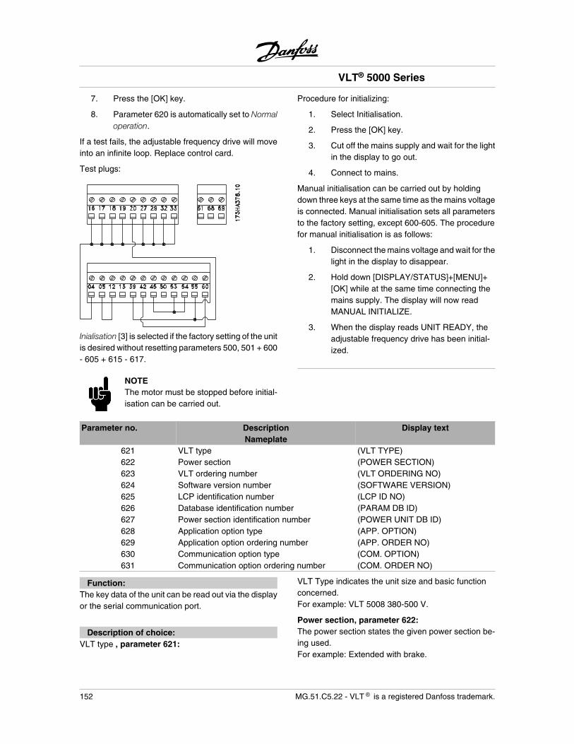
7. Press the [OK] key.
8. Parameter 620 is automatically set to Normaloperation.
If a test fails, the adjustable frequency drive will moveinto an infinite loop. Replace control card.
Test plugs:
Inialisation [3] is selected if the factory setting of the unitis desired without resetting parameters 500, 501 + 600- 605 + 615 - 617.
NOTEThe motor must be stopped before initial-isation can be carried out.
Procedure for initializing:
1. Select Initialisation.
2. Press the [OK] key.
3. Cut off the mains supply and wait for the lightin the display to go out.
4. Connect to mains.
Manual initialisation can be carried out by holdingdown three keys at the same time as the mains voltageis connected. Manual initialisation sets all parametersto the factory setting, except 600-605. The procedurefor manual initialisation is as follows:
1. Disconnect the mains voltage and wait for thelight in the display to disappear.
2. Hold down [DISPLAY/STATUS]+[MENU]+[OK] while at the same time connecting themains supply. The display will now readMANUAL INITIALIZE.
3. When the display reads UNIT READY, theadjustable frequency drive has been initial-ized.
Parameter no. DescriptionNameplate
Display text
621 VLT type (VLT TYPE)622 Power section (POWER SECTION)623 VLT ordering number (VLT ORDERING NO)624 Software version number (SOFTWARE VERSION)625 LCP identification number (LCP ID NO)626 Database identification number (PARAM DB ID)627 Power section identification number (POWER UNIT DB ID)628 Application option type (APP. OPTION)629 Application option ordering number (APP. ORDER NO)630 Communication option type (COM. OPTION)631 Communication option ordering number (COM. ORDER NO)
Function:The key data of the unit can be read out via the displayor the serial communication port.
Description of choice:VLT type , parameter 621:
VLT Type indicates the unit size and basic functionconcerned.For example: VLT 5008 380-500 V.
Power section, parameter 622:The power section states the given power section be-ing used.For example: Extended with brake.
VLT® 5000 Series
152 MG.51.C5.22 - VLT is a registered Danfoss trademark.
VLT ordering number , parameter 623:Ordering number gives the ordering number of the VLTtype in question.For example: 175Z0072.
Software version number, parameter 624:Software version gives the version number.For example: V 3,10.
LCP identification number, parameter 625:The key data of the unit can be read out via the displayor the serial communication port.For example:ID 1,42 2 kB.
Database identification number, parameter 626:The key data of the unit can be read out via the displayor the serial communication port.For example: ID 1,14.
Power section identification number, parameter627:The key data of the unit can be read out via the displayor the serial communication port.For example: ID 1,15.
Application option type, parameter 628:This gives the type of application options fitted with theadjustable frequency drive.
Application option ordering number, parameter629:This gives the ordering number for the application op-tion.
Communication option type, parameter 630:This gives the type of communication options fittedwith the adjustable frequency drive.
Communication option ordering number, parame-ter 631:This gives the ordering number for the communicationoption.
VLT® 5000 Series
MG.51.C5.22 - VLT is a registered Danfoss trademark. 153
Pro
gram
min
g
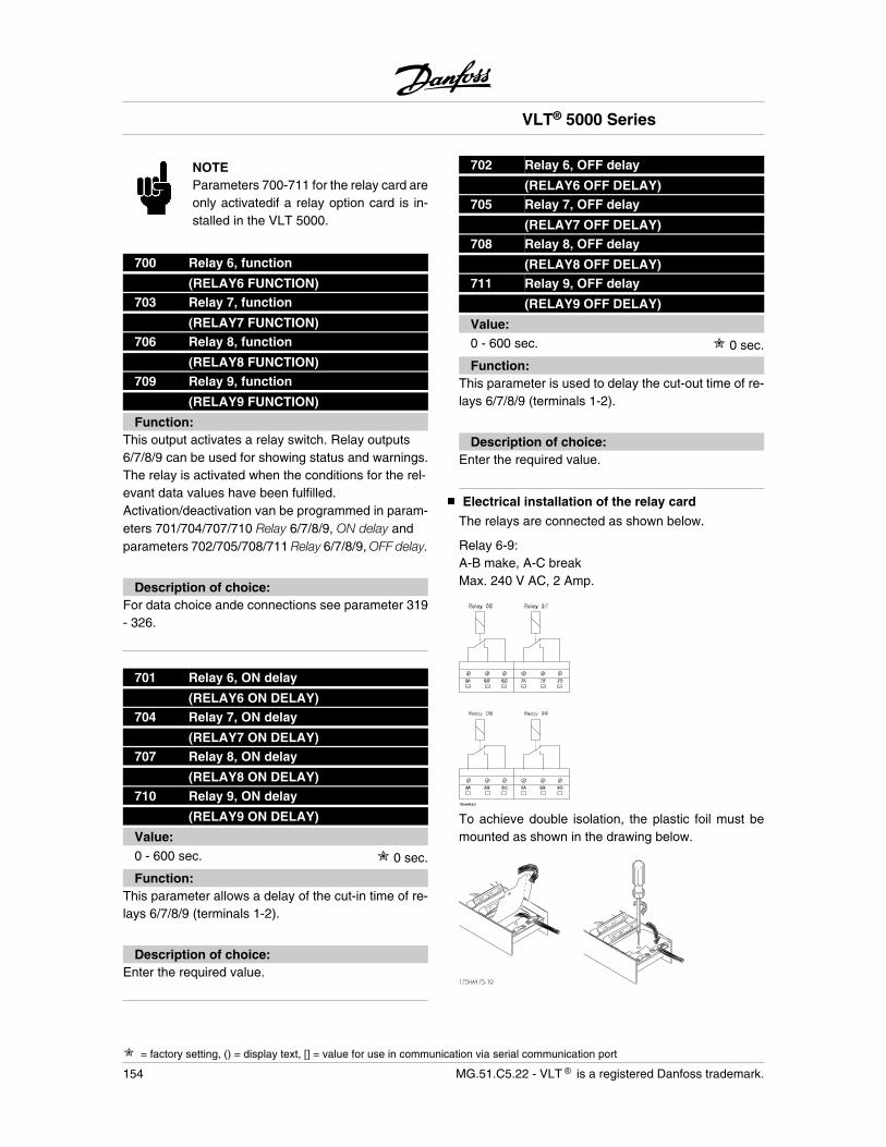
NOTEParameters 700-711 for the relay card areonly activatedif a relay option card is in-stalled in the VLT 5000.
700 Relay 6, function
(RELAY6 FUNCTION)703 Relay 7, function
(RELAY7 FUNCTION)706 Relay 8, function
(RELAY8 FUNCTION)709 Relay 9, function
(RELAY9 FUNCTION)
Function:This output activates a relay switch. Relay outputs6/7/8/9 can be used for showing status and warnings.The relay is activated when the conditions for the rel-evant data values have been fulfilled.Activation/deactivation van be programmed in param-eters 701/704/707/710 Relay 6/7/8/9, ON delay andparameters 702/705/708/711 Relay 6/7/8/9, OFF delay.
Description of choice:For data choice ande connections see parameter 319- 326.
701 Relay 6, ON delay
(RELAY6 ON DELAY)704 Relay 7, ON delay
(RELAY7 ON DELAY)707 Relay 8, ON delay
(RELAY8 ON DELAY)710 Relay 9, ON delay
(RELAY9 ON DELAY)
Value:0 - 600 sec. 0 sec.
Function:This parameter allows a delay of the cut-in time of re-lays 6/7/8/9 (terminals 1-2).
Description of choice:Enter the required value.
702 Relay 6, OFF delay
(RELAY6 OFF DELAY)705 Relay 7, OFF delay
(RELAY7 OFF DELAY)708 Relay 8, OFF delay
(RELAY8 OFF DELAY)711 Relay 9, OFF delay
(RELAY9 OFF DELAY)
Value:0 - 600 sec. 0 sec.
Function:This parameter is used to delay the cut-out time of re-lays 6/7/8/9 (terminals 1-2).
Description of choice:Enter the required value.
Electrical installation of the relay card
The relays are connected as shown below.
Relay 6-9:A-B make, A-C breakMax. 240 V AC, 2 Amp.
To achieve double isolation, the plastic foil must bemounted as shown in the drawing below.
VLT® 5000 Series
= factory setting, () = display text, [] = value for use in communication via serial communication port
154 MG.51.C5.22 - VLT is a registered Danfoss trademark.
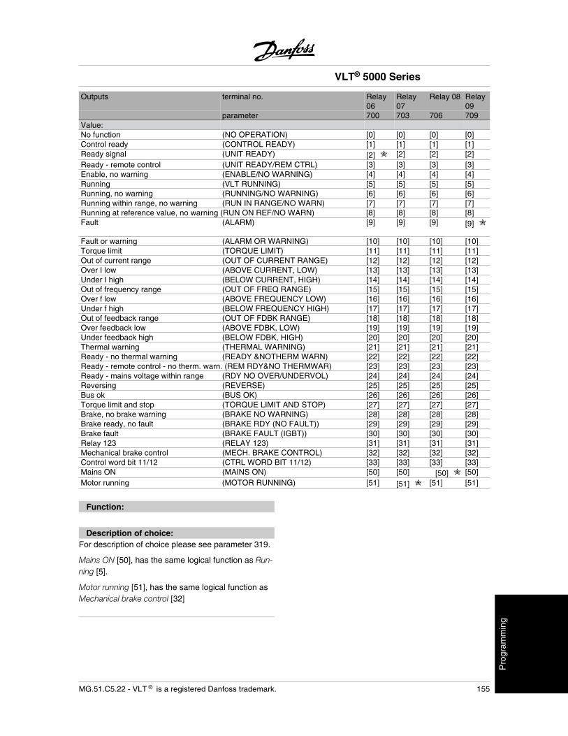
Outputs terminal no. Relay06
Relay07
Relay 08 Relay09
parameter 700 703 706 709Value:No function (NO OPERATION) [0] [0] [0] [0]Control ready (CONTROL READY) [1] [1] [1] [1]Ready signal (UNIT READY) [2] [2] [2] [2]Ready - remote control (UNIT READY/REM CTRL) [3] [3] [3] [3]Enable, no warning (ENABLE/NO WARNING) [4] [4] [4] [4]Running (VLT RUNNING) [5] [5] [5] [5]Running, no warning (RUNNING/NO WARNING) [6] [6] [6] [6]Running within range, no warning (RUN IN RANGE/NO WARN) [7] [7] [7] [7]Running at reference value, no warning (RUN ON REF/NO WARN) [8] [8] [8] [8]Fault (ALARM) [9] [9] [9] [9]
Fault or warning (ALARM OR WARNING) [10] [10] [10] [10]Torque limit (TORQUE LIMIT) [11] [11] [11] [11]Out of current range (OUT OF CURRENT RANGE) [12] [12] [12] [12]Over I low (ABOVE CURRENT, LOW) [13] [13] [13] [13]Under I high (BELOW CURRENT, HIGH) [14] [14] [14] [14]Out of frequency range (OUT OF FREQ RANGE) [15] [15] [15] [15]Over f low (ABOVE FREQUENCY LOW) [16] [16] [16] [16]Under f high (BELOW FREQUENCY HIGH) [17] [17] [17] [17]Out of feedback range (OUT OF FDBK RANGE) [18] [18] [18] [18]Over feedback low (ABOVE FDBK, LOW) [19] [19] [19] [19]Under feedback high (BELOW FDBK, HIGH) [20] [20] [20] [20]Thermal warning (THERMAL WARNING) [21] [21] [21] [21]Ready - no thermal warning (READY &NOTHERM WARN) [22] [22] [22] [22]Ready - remote control - no therm. warn. (REM RDY&NO THERMWAR) [23] [23] [23] [23]Ready - mains voltage within range (RDY NO OVER/UNDERVOL) [24] [24] [24] [24]Reversing (REVERSE) [25] [25] [25] [25]Bus ok (BUS OK) [26] [26] [26] [26]Torque limit and stop (TORQUE LIMIT AND STOP) [27] [27] [27] [27]Brake, no brake warning (BRAKE NO WARNING) [28] [28] [28] [28]Brake ready, no fault (BRAKE RDY (NO FAULT)) [29] [29] [29] [29]Brake fault (BRAKE FAULT (IGBT)) [30] [30] [30] [30]Relay 123 (RELAY 123) [31] [31] [31] [31]Mechanical brake control (MECH. BRAKE CONTROL) [32] [32] [32] [32]Control word bit 11/12 (CTRL WORD BIT 11/12) [33] [33] [33] [33]Mains ON (MAINS ON) [50] [50] [50] [50]Motor running (MOTOR RUNNING) [51] [51] [51] [51]
Function:
Description of choice:For description of choice please see parameter 319.
Mains ON [50], has the same logical function as Run-ning [5].
Motor running [51], has the same logical function asMechanical brake control [32]
VLT® 5000 Series
MG.51.C5.22 - VLT is a registered Danfoss trademark. 155
Pro
gram
min
g
Trouble-shooting
Symptom How to handle1. Motor runs unevenly If the motor runs unevenly, but no fault is given, this may be because the
frequency converter has been wrongly set.Adjust the motor data settings.Contact Danfoss if the new setting does not make the motor run evenly.
2. Motor does not run Check if there is a backlight in the display.If there is a backlight, please check if a fault message is displayed. If yes,please consult the Warnings-section, if no, please refer to symptom 5.If there is no backlight, check if the frequency converter is connected tomains supply. If yes, please refer to symptom 4.
3. Motor does not brake Please refer to Control with brake function.
4. No message or backlight in display Check if the prefuses for the frequency converter have blown.If yes, call Danfoss for assistance.If no, check if the control card is overloaded.If so, disconnect all control signal plugs on the control card and check ifthe fault disappears.If yes, make sure that the 24 V supply is not short-circuited.If no, call Danfoss for assistance.
5. Motor stopped, light in display, but nofault report
Start the frequency converter by pressing [START] on the control panel.Check if the display is frozen, ie. the display cannot be changed or isindefineable.If yes, check if screened cables have been used and are connected cor-rectly.If no, check that the motor is connected and that all motor phases areOK.The frequency converter must be set to run using local references:Parameter 002 = Local operationParameter 003 = desired reference valueConnect 24 V DC to terminal 27.The reference is changed by pressing '+' or '-'.Is the motor running?If yes, check whether control signals to the control card are OK.If no, call Danfoss for assistance.
VLT® 5000 Series
156 MG.51.C5.22 - VLT is a registered Danfoss trademark.
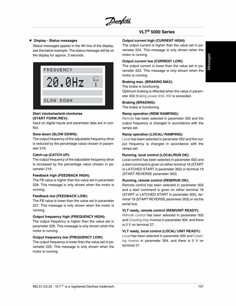
Display - Status messages
Status messages appear in the 4th line of the display,see the below example. The status message will be onthe display for approx. 3 seconds.
20.0HzSLOW DOWN
FREQUENCY
Start clockwise/anti-clockwise(START FORW./REV):Input on digital inputs and parameter data are in con-flict.
Slow-down (SLOW DOWN):The output frequency of the adjustable frequency driveis reduced by the percentage value chosen in param-eter 219.
Catch-up (CATCH UP):The output frequency of the adjustable frequency driveis increased by the percentage value chosen in pa-rameter 219.
Feedback high (FEEDBACK HIGH):The FB value is higher than the value set in parameter228. This message is only shown when the motor isrunning.
Feedback low (FEEDBACK LOW):The FB value is lower than the value set in parameter227. This message is only shown when the motor isrunning.
Output frequency high (FREQUENCY HIGH):The output frequency is higher than the value set inparameter 226. This message is only shown when themotor is running.
Output frequency low (FREQUENCY LOW):The output frequency is lower than the value set in pa-rameter 225. This message is only shown when themotor is running.
Output current high (CURRENT HIGH):The output current is higher than the value set in pa-rameter 224. This message is only shown when themotor is running.
Output current low (CURRENT LOW):The output current is lower than the value set in pa-rameter 223. This message is only shown when themotor is running.
Braking max. (BRAKING MAX):The brake is functioning.Optimum braking is effected when the value in param-eter 402 Braking power limit, KW is exceeded.
Braking (BRAKING):The brake is functioning.
Ramp operation (REM/ RAMPING):Remote has been selected in parameter 002 and theoutput frequency is changed in accordance with theramps set.
Ramp operation (LOCAL/ RAMPING):Local has been selected in parameter 002 and the out-put frequency is changed in accordance with theramps set.
Running, local control (LOCAL/RUN OK):Local control has been selected in parameter 002 anda start command is given on either terminal 18 (STARTor LATCHED START in parameter 302) or terminal 19(START REVERSE parameter 303).
Running, remote control (REM/RUN OK):Remote control has been selected in parameter 002and a start command is given on either terminal 18(START or LATCHED START in parameter 302), ter-minal 19 (START REVERSE parameter 303) or via theserial bus.
VLT ready, remote control (REM/UNIT READY):Remote control has been selected in parameter 002and Coasting stop inverse in parameter 304, and thereis 0 V on terminal 27.
VLT ready, local control (LOCAL/ UNIT READY):Local has been selected in parameter 002 and Coast-ing inverse in parameter 304, and there is 0 V onterminal 27.
VLT® 5000 Series
MG.51.C5.22 - VLT is a registered Danfoss trademark. 157
Mes
sage
s
Quick-stop, remote control (REM/QSTOP):Remote ontrol has been selected in parameter 002 andthe adjustable frequency drive has stopped via aquick-stop signal on terminal 27 (or possibly via theserial communication port).
Quick-stop, local (LOCAL/ QSTOP):Local has been selected in parameter 002 and the ad-justable frequency drive has stopped via a quick-stopsignal on terminal 27 (or possibly via the serial com-munication port).
DC stop, remote control (REM/DC STOP):Remote control has been selected in parameter 002and the adjustable frequency drive has stopped via aDC stop signal on a digital input (or possibly via theserial communication port).
DC braking, local (LOCAL/ DC STOP):Local has been selected in parameter 002 and the ad-justable frequency drive has stopped via a DC brakingsignal on terminal 27 (or possibly via the serial com-munication port).
Stop, remote controlled (REM/STOP):Remote control has been selected in parameter 002and the adjustable frequency drive has stopped via thecontrol panel or a digital input (or possibly via the serialcommunication port).
Stop, local (LOCAL/ STOP):Local has been selected in parameter 002 and the ad-justable frequency drive has stopped via the controlpanel or the digital input (or possibly via the serialcommunication port).
LCP stop, remote (REM/LCP STOP):Remote has been selected in parameter 002 and theadjustable frequency drive has via the control panel.The coast signal on terminal 27 is high.
LCP stop, local (LOCAL/LCP STOP):Local has been selected in parameter 002 and the ad-justable frequency drive has stopped via the controlpanel. The coast signal on terminal 27 is high.
Stand by (STAND BY):Remote control has been selected in parameter 002.The adjustable frequency drive will start when it re-ceives a start signal via a digital input (or the serialcommunication port).
Freeze output (FREEZE OUTPUT):Remote control has been selected in parameter 002together with Freeze reference in parameter 300, 301,
305, 306 or 307, and the terminal in question (16, 17,29, 32 or 33) has been activated (or possibly via theserial communication port).
Jog operation, remote controlled(REM/RUN JOG):Remote control has been selected in parameter 002and Jog in parameter 300, 301, 305, 306 or 307, andthe terminal in question (16, 17, 29, 32 or 33) has beenactivated (or possibly via the serial communicationport).
Jog operation, local (LOCAL/ RUN JOG):Local has been selected in parameter 002 and Jog inparameter 300, 301, 305, 306 or 307, and the terminalin question (16, 17, 29, 32 or 33) has been activated(or possibly via the serial communication port).
Overvoltage control (OVER VOLTAGE CONTROL):The intermediate circuit voltage of the adjustable fre-quency drive is too high. The adjustable frequencydrive is trying to avoid a trip by increasing the outputfrequency.This function is activated in parameter 400.
Automatic Motor Adaptation (AUTO MOTORADAPT):Automatic Motor adaptation is running.
Brake check finished (BRAKECHECK OK):Brake check of brake resistor and brake transistor tes-ted successfully.
Quick Discharge finished (QUICK DISCHARGEOK):Quick discharge has been completed successfully.
Exceptions XXXX (EXCEPTIONS XXXX):The microprocessor of the control card has stoppedand the adjustable frequency drive is out of operation.The cause may be noise on the mains, motor or controlcables, leading to a stop of the control card microproc-essor.Check for EMC-correct connection of these cables.
Ramp stop in fieldbus mode (OFF1):OFF1 means that the drive is stopped by ramp down.The command to stop has been given over a fieldbusor the RS485 serial port (select fieldbus in parameter512).
Coast stop in fieldbus mode (OFF2):OFF2 means that the drive is stopped by coast. Thecommand to stop has been given over a fieldbus or theRS485 serial port (select fieldbus in parameter 512).
VLT® 5000 Series
158 MG.51.C5.22 - VLT is a registered Danfoss trademark.
Quick stop in fieldbus mode (OFF3):OFF3 means that the drive is stopped by quick stop.The command to stop has been given over a fieldbusor the RS485 serial port (select fieldbus in parameter512).
Start not possible (START INHIBIT):The drive is in fieldbus profile mode. OFF1, OFF2 orOFF3 have been activated. OFF1 must be toggled tobe able to start (OFF1 set from 1 to 0 to 1).
Not ready for operation (UNIT NOT READY):The drive is in Fieldbus profile mode (parameter 512).The drive is not ready for operation as bit 00, 01 or 02in the control word is "0", the drive has tripped or thereis no mains supply (only seen on units with 24 V DCsupply).
Ready for operation (CONTROL READY):The drive is ready for operation. For extended unitssupplied with a 24 V DC supply the message alsocomes up when there is not mains supply.
Bus jog, remote controlled (REM/RUN BUS JOG1):Remote control has been selected in parameter 002and the Fieldbus has been selected in parameter 512.Bus Jog has been selected by the fieldbus or serialbus.
Bus jog, remote controlled (REM/RUN BUS JOG2):Remote control has been selected in parameter 002and Fieldbus has been selected in parameter 512. BusJog has been selected by the fieldbus or serial bus.
VLT® 5000 Series
MG.51.C5.22 - VLT is a registered Danfoss trademark. 159
Mes
sage
s
Warnings and alarms
The table gives the different warnings and alarms andindicates whether the fault locks the adjustable fre-quency drive. After Trip locked, the mains supply mustbe cut and the fault must be corrected. Reconnect themains supply and reset the adjustable frequency drivebefore being ready. Wherever a cross is placed underboth Warning and Alarm, this can mean that a warning
precedes the alarm. It can also mean that it is possibleto program whether a given fault is to result in a warn-ing or an alarm. This is possible, e.g. in parameter 404Brake check. After a trip, alarm and warning will flash,but if the fault is removed, only alarm will flash. After areset, the adjustable frequency drive will be ready tostart operation again.
No. Description Warning Alarm Trip locked1 10 Volts low (10 VOLT LOW) X2 Live zero fault (LIVE ZERO ERROR) X X3 No motor (NO MOTOR) X4 Phase fault (MAINS PHASE LOSS) X X X5 Voltage warning high (DC LINK VOLTAGE HIGH) X6 Voltage warning low (DC LINK VOLTAGE LOW) X7 Overvoltage (DC LINK OVERVOLT) X X8 Undervoltage (DC LINK UNDERVOLT) X X9 Inverter overladed (INVERTER TIME) X X10 Motor overloaded (MOTOR TIME) X X11 Motor thermistor (MOTOR THERMISTOR) X X12 Torque limit (TORQUE LIMIT) X X13 Overcurrent (OVERCURRENT) X X X14 Earth fault (EARTH FAULT) X X15 Switch mode fault (SWITCH MODE FAULT) X X16 Short-circuit (CURR.SHORT CIRCUIT) X X17 Standard bus timeout (STD BUS TIMEOUT) X X18 HPFB bus timeout (HPFB TIMEOUT) X X19 Fault in EEprom on power card (EE ERROR POWER CARD) X20 Fault in EEprom on conrol card (EE ERROR CTRL. CARD) X21 Auto-optimisation OK (AUTO MOTOR ADAPT OK) X22 Auto-optimisation not OK (AUTO MOT ADAPT FAIL) X23 Brake test failed (BRAKE TEST FAILED) X X25 Brake resistor short-circuited (BRAKE RESISTOR FAULT ) X26 Brake resistor power 100% (BRAKE POWER 100%) X X27 Brake transistor short-circuited (BRAKE IGBT FAULT) X29 Heat-sink temperature too high (HEAT SINK OVER TEMP.) X X30 Motor phase U missing (MISSING MOT.PHASE U) X31 Motor phase V missing (MISSING MOT.PHASE V) X32 Motor phase W missing (MISSING MOT.PHASE W) X33 Quick discharge not OK (QUICK DISCHARGE FAIL) X X34 Profibus communication fault (PROFIBUS COMM. FAULT) X X35 Out of frequency range (OUT FREQ RNG/ROT LIM) X36 Mains failure (MAINS FAILURE) X X37 Inverter fault (INVERTER FAULT) X X39 Check parameters 104 and 106 (CHECK P.104 & P.106) X40 Check parameters 103 and 105 (CHECK P.103 & P.105) X41 Motor too big (Motor too big) X42 Motor too small (Motor too small) X43 Brake fault (BRAKE FAULT) X X44 Encoder loss (ENCODER FAULT) X X
VLT® 5000 Series
160 MG.51.C5.22 - VLT is a registered Danfoss trademark.
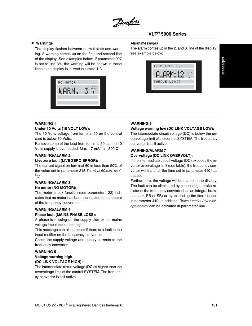
Warnings
The display flashes between normal state and warn-ing. A warning comes up on the first and second lineof the display. See examples below. If parameter 027is set to line 3/4, the warning will be shown in theselines if the display is in read-out state 1-3.
SETUP
1
NO MOTOR
WARN. 3
Alarm messagesThe alarm comes up in the 2. and 3. line of the display,see example below:
ALARM:12 SETUP
1
TRIP (RESET)
TORQUE LIMIT
WARNING 1Under 10 Volts (10 VOLT LOW):The 10 Volts voltage from terminal 50 on the controlcard is below 10 Volts.Remove some of the load from terminal 50, as the 10Volts supply is overloaded. Max. 17 mA/min. 590 .
WARNING/ALARM 2Live zero fault (LIVE ZERO ERROR):The current signal on terminal 60 is less than 50% ofthe value set in parameter 315 Terminal 60,min. scal-ing.
WARNING/ALARM 3No motor (NO MOTOR):The motor check function (see parameter 122) indi-cates that no motor has been connected to the outputof the frequency converter.
WARNING/ALARM 4Phase fault (MAINS PHASE LOSS):A phase is missing on the supply side or the mainsvoltage imbalance is too high.This message can also appear if there is a fault in theinput rectifier on the frequency converter.Check the supply voltage and supply currents to thefrequency converter.
WARNING 5Voltage warning high(DC LINK VOLTAGE HIGH):The intermediate circuit voltage (DC) is higher than theovervoltage limit of the control SYSTEM. The frequen-cy converter is still active.
WARNING 6Voltage warning low (DC LINK VOLTAGE LOW):The intermediate circuit voltage (DC) is below the un-dervoltage limit of the control SYSTEM. The frequencyconverter is still active.
WARNING/ALARM 7Overvoltage (DC LINK OVERVOLT):If the intermediate circuit voltage (DC) exceeds the in-verter overvoltage limit (see table), the frequency con-verter will trip after the time set in parameter 410 haspassed.Furthermore, the voltage will be stated in the display.The fault can be eliminated by connecting a brake re-sistor (if the frequency converter has an integral brakechopper, EB or SB) or by extending the time chosenin parameter 410. In addition, Brake function/overvolt-age control can be activated in parameter 400.
VLT® 5000 Series
MG.51.C5.22 - VLT is a registered Danfoss trademark. 161
Mes
sage
s
Alarm/warning limits:VLT 5000 Series 3 x 200 - 240 V 3 x 380 - 500 V 3 x 525 - 600 V 3 X 525 - 690 v
[VDC] [VDC] [VDC] [VDC]Undervoltage 211 402 557 553Voltage warning low 222 423 585 585Voltage warning high (w/o brake - w/brake)
384/405 801/8401) 943/965 1084/1109
Overvoltage 425 855 975 1130
The voltages stated are the intermediate circuit volt-age of the frequency converter with a tolerance of ± 5%. The corresponding mains voltage is the intermedi-ate circuit voltage divided by 1.351) VLT 5122 - VLT 5552: 817/828 VDC.
WARNING/ALARM 8Undervoltage (DC LINK UNDERVOLT):If the intermediate circuit voltage (DC) drops below theinverter lower voltage limit (see table on previouspage), it will be checked whether 24 V power supply isconnected.If no 24 V power supply is connected, the frequencyconverter will trip after a given time that depends onthe unit.Furthermore, the voltage will be stated in the display.Check whether the supply voltage matches the fre-quency converter, see technical data.
WARNING/ALARM 9Inverter overload (INVERTER TIME):The electronic, thermal inverter protection reports thatthe frequency converter is about to cut out because ofan overload (too high current for too long). The counterfor electronic, thermal inverter protection gives a warn-ing at 98% and trips at 100%, while giving an alarm.The frequency converter cannot be reset until thecounter is below 90%.The fault is that the frequency converter is overloadedby more than 100% for too long.
WARNING/ALARM 10Motor overtemperature (MOTOR TIME):According to the electronic thermal protection (ETR),the motor is too hot. Parameter 128 allows a choice ofwhether the frequency converter is to give a warningor an alarm when the counter reaches 100%. The faultis that the motor is overloaded by more than 100% fortoo long. Check that motor parameters 102-106 havebeen set correctly.
WARNING/ALARM 11Motor thermistor (MOTOR THERMISTOR):The thermistor or the thermistor connection has beendisconnected. Parameter 128 allows a choice ofwhether the frequency converter is to give a warningor an alarm. Check that the thermistor has been cor-rectly connected between terminal 53 or 54 (analoguevoltage input) and terminal 50 (+ 10 Volts supply).
WARNING/ALARM 12Torque limit (TORQUE LIMIT):The torque is higher than the value in parameter 221(in motor operation) or the torque is higher than thevalue in parameter 222 (in regenerative operation).
WARNING/ALARM 13Overcurrent (OVERCURRENT):The inverter peak current limit (approx. 200% of therated current) has been exceeded. The warning willlast approx. 1-2 seconds, following which the frequen-cy converter will trip, while giving an alarm. Turn off thefrequency converter and check whether the motorshaft can be turned and whether the motor size match-es the frequency converter.If extended mechanical brake control is selected, tripcan be reset externally.
ALARM: 14Earth fault (Earth fault):There is a discharge from the output phases to earth,either in the cable between the frequency converterand the motor or in the motor itself.Turn off the frequency converter and remove the earthfault.
ALARM: 15Switch mode fault (SWITCH MODE FAULT):Fault in the switch mode power supply (internal ± 15 Vsupply).Contact your Danfoss supplier.
VLT® 5000 Series
162 MG.51.C5.22 - VLT is a registered Danfoss trademark.
ALARM: 16Short-circuiting (CURR.SHORT CIRCUIT):There is short-circuiting on the motor terminals or inthe motor itself.Turn off the frequency converter and remove the short-circuit.
WARNING/ALARM 17Standard bus timeout (STD BUS TIMEOUT)There is no communication to the frequency converter.The warning will only be active when parameter 514has been set to another value than OFF.If parameter 514 has been set to stop and trip, it willfirst give a warning and then ramp down until it trips,while giving an alarm.Parameter 513 Bus time interval could possibly be in-creased.
WARNING/ALARM 18HPFB bus timeout (HPFB BUS TIMEOUT )There is no communication with the frequency con-verter.The warning will only be active when parameter 804has been set to another value than OFF.If parameter 804 has been set to Stop and trip, it willfirst give a warning and then ramp down until it trips,while giving an alarm.Parameter 803 Bus time interval could possibly be in-creased.
WARNING 19Fault in the EEprom on the power card(EE ERROR POWER CARD)There is a fault on the power card EEPROM. The fre-quency converter will continue to function, but is likelyto fail at the next power-up. Contact your Danfoss sup-plier.
WARNING 20Fault in the EEprom on the control card(EE ERROR CTRL CARD)There is a fault in the EEPROM on the control card.The frequency converter will continue to function, butis likely to fail at the next power-up. Contact your Dan-foss supplier.
ALARM 21Auto-optimisation OK(AUTO MOTOR ADAPT OK)The automatic motor tuning is OK and the frequencyconverter is now ready for operation.
ALARM: 22Auto-optimisation not OK(AUTO MOT ADAPT FAIL)A fault has been found during automatic motor adap-tation. The text shown in the display indicates a faultmessage. The figure after the text is the error code,which can be seen in the fault log in parameter 615.
CHECK P.103,105 [0]See section Automatic motor adaptation, AMA.
LOW P.105 [1]See section Automatic motor adaptation, AMA.
ASYMMETRICAL IMPEDANCE [2]See section Automatic motor adaptation, AMA.
MOTOR TOO BIG [3]See section Automatic motor adaptation, AMA.
MOTOR TOO SMALL [4]See section Automatic motor adaptation, AMA.
TIME OUT [5]See section Automatic motor adaptation, AMA.
INTERRUPTED BY USER [6]See section Automatic motor adaptation, AMA.
INTERNAL FAULT [7]See section Automatic motor adaptation, AMA.
LIMIT VALUE FAULT [8]See section Automatic motor adaptation, AMA.
MOTOR ROTATES [9]See section Automatic motor adaptation, AMA.
NOTEAMA can only be carried out if there areno alarms during tuning.
WARNING/ALARM 23Fault during brake test (BRAKE TEST FAILED):The brake test is only run after power-up. If Warninghas been selected in parameter 404, the warning willcome when the brake test finds a fault.If Trip has been selected in parameter 404, the fre-quency converter will trip when the brake test finds afault.The brake test may fail for the following reasons:No brake resistor connected or fault in the connec-tions; defective brake resistor or defective brake tran-sistor. A warning or alarm will mean that the brakefunction is still active.
VLT® 5000 Series
MG.51.C5.22 - VLT is a registered Danfoss trademark. 163
Mes
sage
s
WARNING 25Brake resistor fault(BRAKE RESISTOR FAULT):The brake resistor is monitored during operation andif it short-circuits, the brake function is disconnectedand the warning comes up. The frequency converterwill still be able to work, although without the brakefunction. Turn off the frequency converter and replacethe brake resistor.
ALARM/WARNING 26Brake resistor power 100%(BRAKE PWR WARN 100%):The power transmitted to the brake resistor is calcula-ted as a percentage, as a mean value over the last 120sec., on the basis of the resistance value of the brakeresistor (parameter 401) and the intermediate circuitvoltage. The warning is active when the dissipatedbraking power is higher than 100%. If Trip [2] has beenselected in parameter 403, the frequency converterwill cut out while giving this alarm.
WARNING 27Brake transistor fault(BRAKE IGBT FAULT):The brake transistor is monitored during operation andif it short-circuits, the brake function is disconnectedand the warning comes up. The frequency converterwill still be able to run, but since the brake transistorhas short-circuited, substantial power will be transmit-ted to the brake resistor, even if it is inactive.Turn off the frequency converter and remove the brakeresistor.
Warning: There is a risk of substantialpower being transmitted to the brake re-sis- tor if the brake transistor has short-circuited.
ALARM: 29Heat sink temperature too high(HEAT SINK OVER TEMP.):If the enclosure is IP 00 or IP 20/NEMA 1, the cut-outtemperature of the heat-sink is 90°C. If IP 54 is used,the cut-out temperature is 80°C.The tolerance is ± 5°C. The temperature fault cannotbe reset, until the temperature of the heat-sink is below60°C.The fault could be the following:- Ambient temperature too high- Too long motor cable
- Too high switching frequency.
ALARM: 30Motor phase U missing(MISSING MOT.PHASE U):Motor phase U between frequency converter and mo-tor is missing.Turn off the frequency converter and check motorphase U.
ALARM: 31Motor phase V missing(MISSING MOT.PHASE V):Motor phase V between frequency converter and mo-tor is missing.Turn off the frequency converter and check motorphase V.
ALARM: 32Motor phase W missing(MISSING MOT.PHASE W):Motor phase W between frequency converter and mo-tor is missing.Turn off the frequency converter and check motorphase W.
ALARM: 33Quick discharge not OK(QUICK DISCHARGE NOT OK):Check whether a 24 Volt external DC supply has beenconnected and that an external brake/discharge resis-tor has been fitted.
WARNING/ALARM: 34Fieldbus communication fault(FIELDBUS COMMUNICATION FAULT):The fieldbus on the communication option card is notworking.
WARNING: 35Out of frequency range(OUT OF FREQUENCY RANGE):This warning is active if the output frequency hasreached its Output frequency low limit (parameter 201)or Output frequency high limit (parameter 202). If thefrequency converter is in Process control, closed loop(parameter 100), the warning will be active in the dis-play. If the frequency converter is in another mode thanProcess control, closed loop, bit 008000 Out of fre-quency range in extended status word will be active,while there will be no warning in the display.
VLT® 5000 Series
164 MG.51.C5.22 - VLT is a registered Danfoss trademark.
WARNING/ALARM: 36Mains failure (MAINS FAILURE):This warning/alarm is only active if the supply voltageto the frequency converter is lost and if parameter 407Mains fault has been set to another value than OFF.If parameter 407 has been set to Contr. ramp-downtrip [2], the frequency converter will first give a warningand then ramp down and trip, while giving an alarm.Check the fuses to the frequency converter.
ALARM: 37Inverter fault (Inverter fault):IGBT or the power card is defective. Contact yourDanfoss supplier.Auto-optimisation warningsAutomatic motor adaptation has stopped, since someparameters have probably been set wrongly, or themotor used is too big/small for AMA to be carried out.A choice must thus be made by pressing [CHANGEDATA] and choosing `Continue' + [OK] or `Stop' +[OK].If parameters need to be changed, select `Stop'; startup AMA all over.
WARNING: 39CHECK P.104,106The setting of parameter 102, 104 or 106 is probablywrong. Check the setting and choose `Continue' or`Stop'.
WARNING: 40CHECK P.103,105The setting of parameter 102, 103 or 105 is probablywrong. Check the setting and choose `Continue' or`Stop'.
WARNING: 41MOTOR TOO BIGThe motor used is probably too big for AMA to be car-ried out. The setting in parameter 102 may not matchthe motor. Check the motor and choose `Continue' or`Stop'.
WARNING: 42MOTOR TOO SMALLThe motor used is probably too small for AMA to becarried out. The setting in parameter 102 may notmatch the motor. Check the motor and choose `Con-tinue' or `Stop'.
ALARM: 43Brake fault (BRAKE FAULT)A fault has arisen on the brake. The text shown in thedisplay indicates a fault message. The figure after thetext is the fault code that can be seen in the fault log,parameter 615.
Brake check failed (BRAKE CHECK FAILED) [0]The brake check carried out during power-up indicatesthat the brake has been disconnected. Check whetherthe brake has been connected correctly and that it hasnot been disconnected.
Brake resistor short-circuited(BRAKE RESISTOR FAULT) [1]The brake output has short-circuited. Replace thebrake resistor.
Brake IGBT short-circuited(BRAKE IGBT FAULT) [2]The brake IGBT has short-circuited. This fault meansthat the unit is not able to stop the brake and that, con-sequently, the resistor is constant being energized.
WARNING/ALARM: 44Encoder loss (ENCODER FAULT)The encoder signal is interrupted from terminal 32 or33. Check the connections.
WARNING/ALARM: 57Overcurrent (OVERCURRENT)As warning/alarm 13, but in this case the warning/alarm occurs together with a quick stop.
ALARM: 60Safety stop (EXTERNAL FAULT)Terminal 27 (parameter 304 Digital Inputs) has beenprogrammed for a safety interlock [3] and is a logic '0'.
VLT® 5000 Series
MG.51.C5.22 - VLT is a registered Danfoss trademark. 165
Mes
sage
s
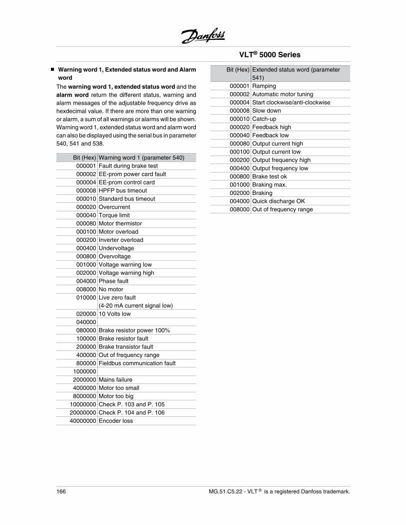
Warning word 1, Extended status word and Alarmword
The warning word 1, extended status word and thealarm word return the different status, warning andalarm messages of the adjustable frequency drive ashexdecimal value. If there are more than one warningor alarm, a sum of all warnings or alarms will be shown.Warning word 1, extended status word and alarm wordcan also be displayed using the serial bus in parameter540, 541 and 538.
Bit (Hex) Warning word 1 (parameter 540)000001 Fault during brake test000002 EE-prom power card fault000004 EE-prom control card000008 HPFP bus timeout000010 Standard bus timeout000020 Overcurrent000040 Torque limit000080 Motor thermistor000100 Motor overload000200 Inverter overload000400 Undervoltage000800 Overvoltage001000 Voltage warning low002000 Voltage warning high004000 Phase fault008000 No motor010000 Live zero fault
(4-20 mA current signal low)020000 10 Volts low040000080000 Brake resistor power 100%100000 Brake resistor fault200000 Brake transistor fault400000 Out of frequency range800000 Fieldbus communication fault
10000002000000 Mains failure4000000 Motor too small8000000 Motor too big
10000000 Check P. 103 and P. 10520000000 Check P. 104 and P. 10640000000 Encoder loss
Bit (Hex) Extended status word (parameter541)
000001 Ramping000002 Automatic motor tuning000004 Start clockwise/anti-clockwise000008 Slow down000010 Catch-up000020 Feedback high000040 Feedback low000080 Output current high000100 Output current low000200 Output frequency high000400 Output frequency low000800 Brake test ok001000 Braking max.002000 Braking004000 Quick discharge OK008000 Out of frequency range
VLT® 5000 Series
166 MG.51.C5.22 - VLT is a registered Danfoss trademark.
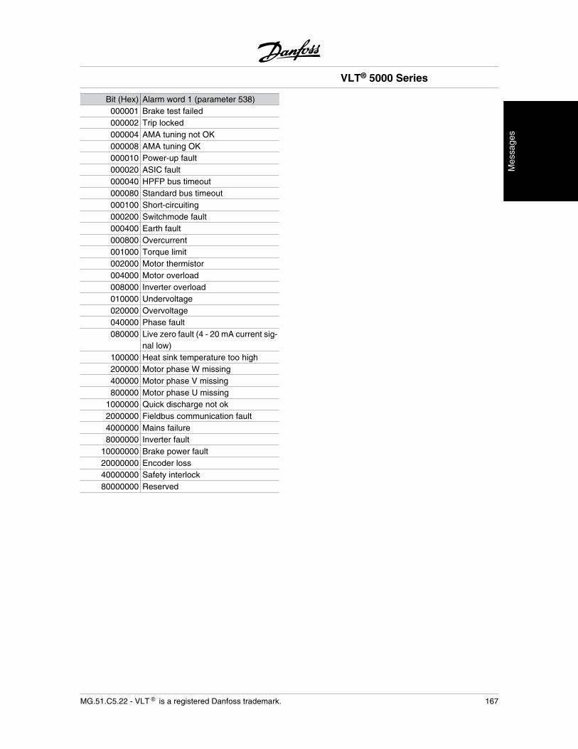
Bit (Hex) Alarm word 1 (parameter 538)000001 Brake test failed000002 Trip locked000004 AMA tuning not OK000008 AMA tuning OK000010 Power-up fault000020 ASIC fault000040 HPFP bus timeout000080 Standard bus timeout000100 Short-circuiting000200 Switchmode fault000400 Earth fault000800 Overcurrent001000 Torque limit002000 Motor thermistor004000 Motor overload008000 Inverter overload010000 Undervoltage020000 Overvoltage040000 Phase fault080000 Live zero fault (4 - 20 mA current sig-
nal low)100000 Heat sink temperature too high200000 Motor phase W missing400000 Motor phase V missing800000 Motor phase U missing
1000000 Quick discharge not ok2000000 Fieldbus communication fault4000000 Mains failure8000000 Inverter fault
10000000 Brake power fault20000000 Encoder loss40000000 Safety interlock80000000 Reserved
VLT® 5000 Series
MG.51.C5.22 - VLT is a registered Danfoss trademark. 167
Mes
sage
s
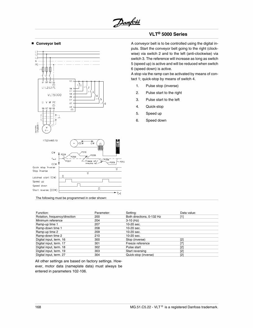
Conveyor belt A conveyor belt is to be controlled using the digital in-puts. Start the conveyor belt going to the right (clock-wise) via switch 2 and to the left (anti-clockwise) viaswitch 3. The reference will increase as long as switch5 (speed up) is active and will be reduced when switch6 (speed down) is active.A stop via the ramp can be activated by means of con-tact 1; quick-stop by means of switch 4.
1. Pulse stop (inverse)
2. Pulse start to the right
3. Pulse start to the left
4. Quick-stop
5. Speed up
6. Speed down
The following must be programmed in order shown:
Function: Parameter: Setting: Data value:Rotation, frequency/direction 200 Both directions, 0-132 Hz [1]Minimum reference 204 3-10 (Hz)Ramp-up time 1 207 10-20 sec.Ramp-down time 1 208 10-20 sec.Ramp-up time 2 209 10-20 sec.Ramp-down time 2 210 10-20 sec.Digital input, term. 16 300 Stop (inverse) [2]Digital input, term. 17 301 Freeze reference [7]Digital input, term. 18 302 Pulse start [2]Digital input, term. 19 303 Start reversing [2]Digital input, term. 27 304 Quick-stop (inverse) [2]
All other settings are based on factory settings. How-ever, motor data (nameplate data) must always beentered in parameters 102-106.
VLT® 5000 Series
168 MG.51.C5.22 - VLT is a registered Danfoss trademark.
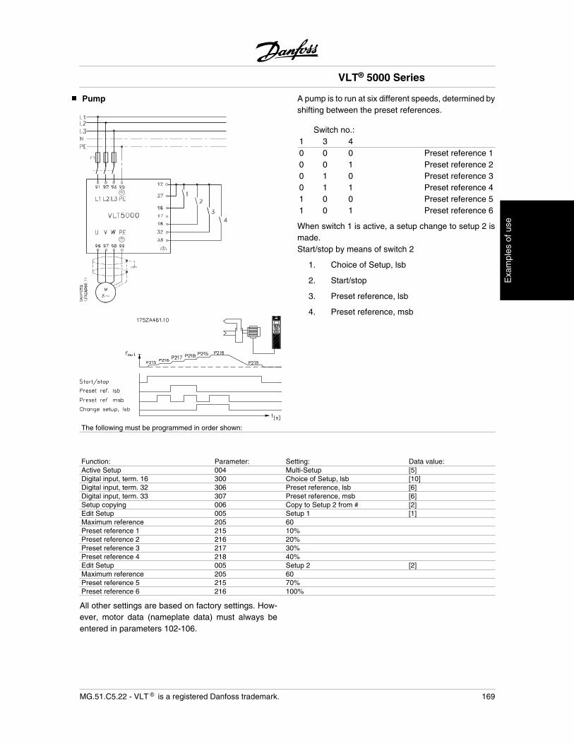
Pump A pump is to run at six different speeds, determined byshifting between the preset references.
Switch no.: 1 3 40 0 0 Preset reference 10 0 1 Preset reference 20 1 0 Preset reference 30 1 1 Preset reference 41 0 0 Preset reference 51 0 1 Preset reference 6
When switch 1 is active, a setup change to setup 2 ismade.Start/stop by means of switch 2
1. Choice of Setup, lsb
2. Start/stop
3. Preset reference, lsb
4. Preset reference, msb
The following must be programmed in order shown:
Function: Parameter: Setting: Data value:Active Setup 004 Multi-Setup [5]Digital input, term. 16 300 Choice of Setup, lsb [10]Digital input, term. 32 306 Preset reference, lsb [6]Digital input, term. 33 307 Preset reference, msb [6]Setup copying 006 Copy to Setup 2 from # [2]Edit Setup 005 Setup 1 [1]Maximum reference 205 60Preset reference 1 215 10%Preset reference 2 216 20%Preset reference 3 217 30%Preset reference 4 218 40%Edit Setup 005 Setup 2 [2]Maximum reference 205 60Preset reference 5 215 70%Preset reference 6 216 100%
All other settings are based on factory settings. How-ever, motor data (nameplate data) must always beentered in parameters 102-106.
VLT® 5000 Series
MG.51.C5.22 - VLT is a registered Danfoss trademark. 169
Exa
mpl
es o
f use
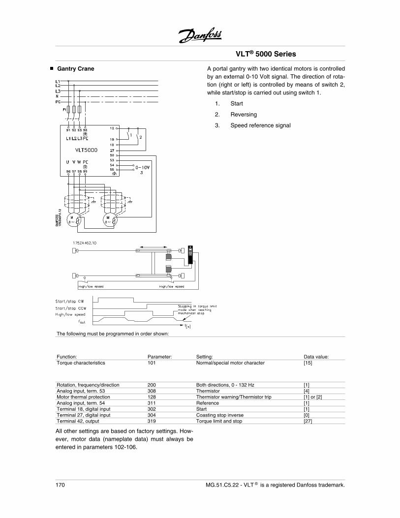
Gantry Crane A portal gantry with two identical motors is controlledby an external 0-10 Volt signal. The direction of rota-tion (right or left) is controlled by means of switch 2,while start/stop is carried out using switch 1.
1. Start
2. Reversing
3. Speed reference signal
The following must be programmed in order shown:
Function: Parameter: Setting: Data value:Torque characteristics 101 Normal/special motor character [15]
Rotation, frequency/direction 200 Both directions, 0 - 132 Hz [1]Analog input, term. 53 308 Thermistor [4]Motor thermal protection 128 Thermistor warning/Thermistor trip [1] or [2]Analog input, term. 54 311 Reference [1]Terminal 18, digital input 302 Start [1]Terminal 27, digital input 304 Coasting stop inverse [0]Terminal 42, output 319 Torque limit and stop [27]
All other settings are based on factory settings. How-ever, motor data (nameplate data) must always beentered in parameters 102-106.
VLT® 5000 Series
170 MG.51.C5.22 - VLT is a registered Danfoss trademark.
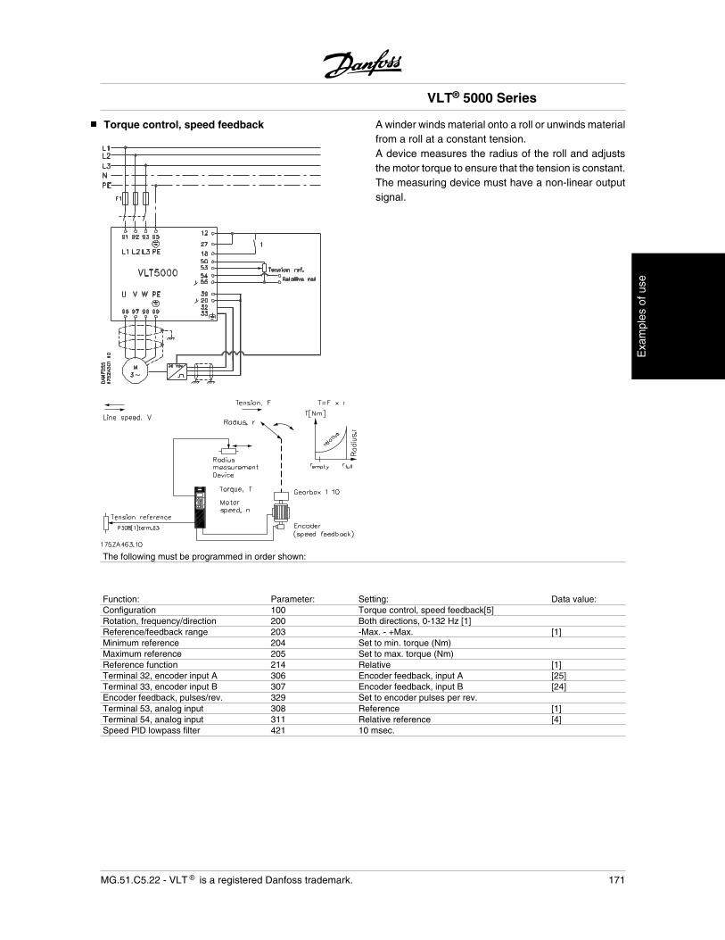
Torque control, speed feedback A winder winds material onto a roll or unwinds materialfrom a roll at a constant tension.A device measures the radius of the roll and adjuststhe motor torque to ensure that the tension is constant.The measuring device must have a non-linear outputsignal.
The following must be programmed in order shown:
Function: Parameter: Setting: Data value:Configuration 100 Torque control, speed feedback[5]Rotation, frequency/direction 200 Both directions, 0-132 Hz [1]Reference/feedback range 203 -Max. - +Max. [1]Minimum reference 204 Set to min. torque (Nm)Maximum reference 205 Set to max. torque (Nm)Reference function 214 Relative [1]Terminal 32, encoder input A 306 Encoder feedback, input A [25]Terminal 33, encoder input B 307 Encoder feedback, input B [24]Encoder feedback, pulses/rev. 329 Set to encoder pulses per rev.Terminal 53, analog input 308 Reference [1]Terminal 54, analog input 311 Relative reference [4]Speed PID lowpass filter 421 10 msec.
VLT® 5000 Series
MG.51.C5.22 - VLT is a registered Danfoss trademark. 171
Exa
mpl
es o
f use
VLT 5000 controllers
VLT 5000 has three inbuilt controllers: one for speedcontrol, one for process control and one for torquecontrol.Speed control and process control are in the form of aPID controller that requires a feedback to an input.Torque control is in the form of a PI controller that doesnot require a feedback, since the torque is calculatedby the adjustable frequency drive on the basis of thecurrent measured.
Setting of speed and process controllerWith respect to both PID controllers, there are a num-ber of settings which are made in the same parame-ters; however, the choice of controller type will affectthe choices to be made under the common parame-ters.In parameter 100 Configuration, a choice is made ofcontroller, Speed control, closed loop or Process con-trol, closed loop.
Feedback signal:A feedback range must be set for both controllers. Thisfeedback range at the same time limits the possiblereference range, which means that if the sum of allreferences is outside the feedback range, the refer-ence will be limited to being within this range. Thefeedback range is set in the units that belong to theapplication (Hz, RPM, bar, °C, etc.). Setting is effecteddirectly in a parameter for the individual input terminal,thereby deciding whether it should be used for feed-back in connection with one of the controllers. Inputsthat are not used can be disabled, which will ensurethat they do not disturb control. If feedback has beenselected on two terminals at the same time, these twosignals will be added up.
Reference:For both controllers, it is possible to set four presetreferences. These can be set between -100% and+100% of the maximum reference or the sum of theexternal references. External references can be ana-log signals, pulse signals and/or serial communication.All references will be added and the sum will be thereference for subsequent regulation.It is possible to limit the reference range to a rangesmaller than the feedback range. This can be an ad-vantage if it is to be avoided that an unintended changeof an external reference makes the sum of referencesmove too far away from the optimum reference. As
with the feedback range, the reference range is set inthe units that belong to the applications in question.
Speed control:This PID control has been optimized for use in appli-cations with a need to maintain a given motor speed.
The parameters that are specific to the speed control-ler are parameters 417 to 421.
PID for process control:This PID control has been optimized for process con-trol. This controller does not have a feedforward facili-ty, but a number of special features that are relevantto process control.
There is a choice of whether normal control is required,in which the speed is increased in the case of an errorbetween the reference and the feedback, or whetherinverse control is to be applied, in which the speed isreduced in the case of an error.There is also a choice of whether the integrator is tocontinue integrating in the case of an error, even if VLT5000 is at the minimum/maximum frequency or at thecurrent limit. If VLT 5000 is in such a borderline situa-tion, any attempt to change the motor speed will berestricted by this limit. The integrator comes from theworks preset to stop integrating. Integration will be ad-justed to a gain that corresponds to the given outputfrequency.In certain applications, it is either difficult or completelyimpossible to measure such a factor as the level. Insuch cases, it can be necessary to allow the integratorto continue integrating on the fault, even if the motorspeed cannot be changed. This will make the integra-tor work as a kind of counter, i.e. once the feedbackindicates that the speed must be changed in a directionaway from the borderline situation, the integration willgive this change a delay that depends on the time forwhich the integrator has overcompensated for the pre-vious error.
Furthermore, it is possible to program a starting fre-quency in which VLT 5000 will wait without activatingthe controller until this frequency has been reached.This makes it possible, for example, to quickly build upthe necessary static pressure in a pumping system.
VLT® 5000 Series
172 MG.51.C5.22 - VLT is a registered Danfoss trademark.

PID process control, continued:The Proportional gain, Integration time and Differen-tiation time of the process controller are set in individ-ual parameters, and the setting ranges are adapted toprocess control requirements.
As in speed control, it is possible to limit the influenceof the differentiator in relation to swift changes in theerror between the reference and the feedback signal.
Also available is a lowpass filter for the process con-troller. This can be set to remove a much greater shareof the feedback signal oscillations than the lowpassfilter of the speed controller does. This is because mostfans and pump applications react relatively slowly,which is why it can be an advantage to feed as stablea signal as possible to the process controller.
The parameters that are specific to the process con-troller are parameters 437 to 444.
Setting of torque controller (open loop):This control is selected if Torque control, open loophas been selected in 100 Configuration.When this mode has been selected, the reference willuse the Nm unit.Control is in the form of a PI that requires no feedback,since the torque is calculated on the basis of the cur-rent measurement of VLT 5000. The proportional gainis set as a percentage in parameter 433 Torque pro-portional gain and the integration time is set in param-eter 434 Torque integration time. However, both thesehave been set at the works and normally require nomodification.
VLT® 5000 Series
MG.51.C5.22 - VLT is a registered Danfoss trademark. 173
Exa
mpl
es o
f use
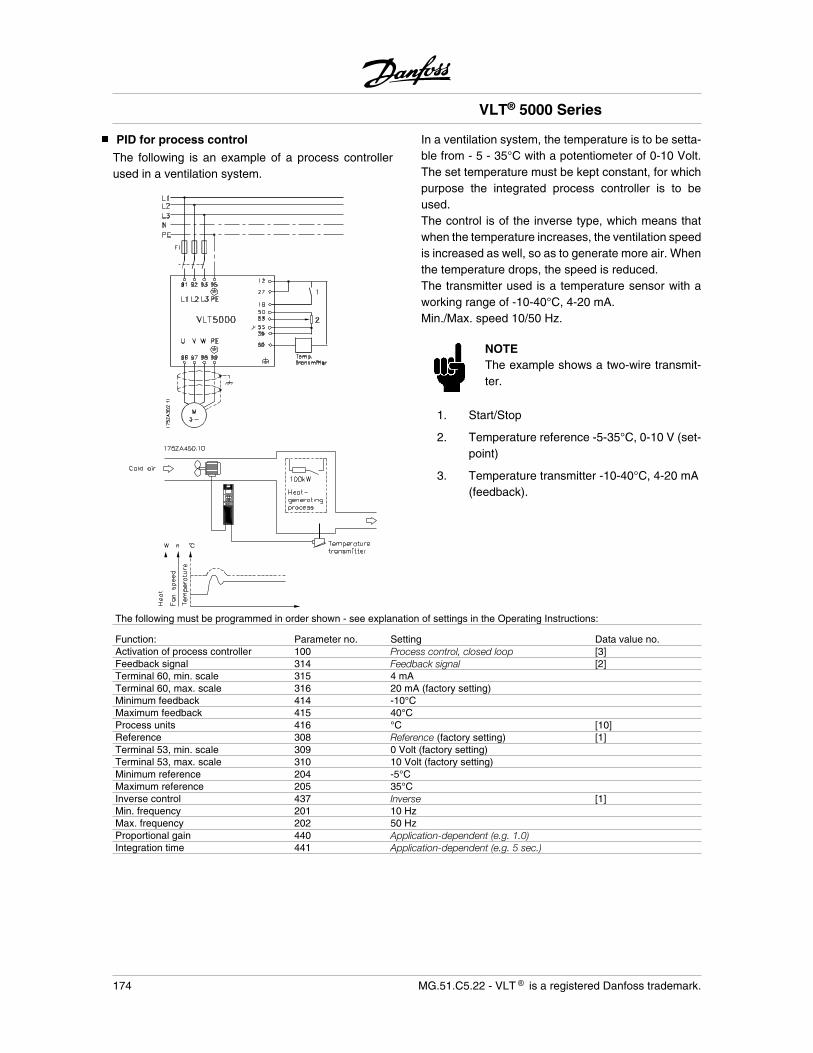
PID for process control
The following is an example of a process controllerused in a ventilation system.
In a ventilation system, the temperature is to be setta-ble from - 5 - 35°C with a potentiometer of 0-10 Volt.The set temperature must be kept constant, for whichpurpose the integrated process controller is to beused.The control is of the inverse type, which means thatwhen the temperature increases, the ventilation speedis increased as well, so as to generate more air. Whenthe temperature drops, the speed is reduced.The transmitter used is a temperature sensor with aworking range of -10-40°C, 4-20 mA.Min./Max. speed 10/50 Hz.
NOTEThe example shows a two-wire transmit-ter.
1. Start/Stop
2. Temperature reference -5-35°C, 0-10 V (set-point)
3. Temperature transmitter -10-40°C, 4-20 mA(feedback).
The following must be programmed in order shown - see explanation of settings in the Operating Instructions:
Function: Parameter no. Setting Data value no.Activation of process controller 100 Process control, closed loop [3]Feedback signal 314 Feedback signal [2]Terminal 60, min. scale 315 4 mATerminal 60, max. scale 316 20 mA (factory setting)Minimum feedback 414 -10°CMaximum feedback 415 40°CProcess units 416 °C [10]Reference 308 Reference (factory setting) [1]Terminal 53, min. scale 309 0 Volt (factory setting)Terminal 53, max. scale 310 10 Volt (factory setting)Minimum reference 204 -5°CMaximum reference 205 35°CInverse control 437 Inverse [1]Min. frequency 201 10 HzMax. frequency 202 50 HzProportional gain 440 Application-dependent (e.g. 1.0)Integration time 441 Application-dependent (e.g. 5 sec.)
VLT® 5000 Series
174 MG.51.C5.22 - VLT is a registered Danfoss trademark.
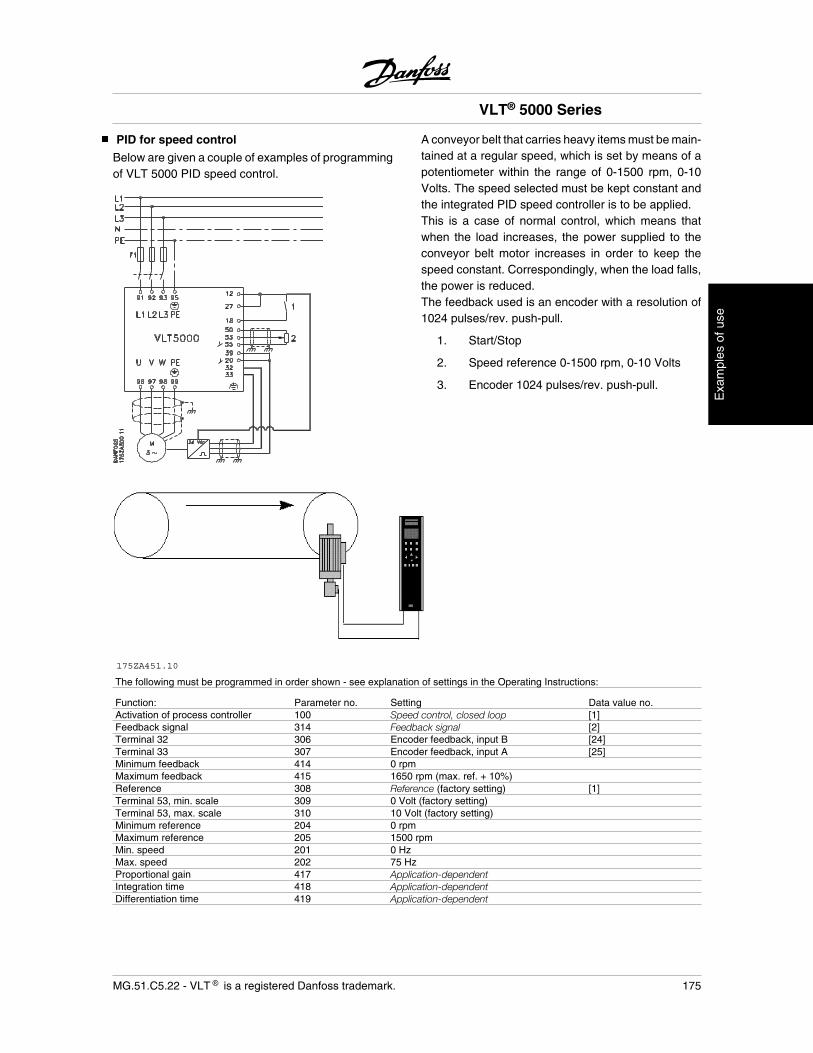
PID for speed control
Below are given a couple of examples of programmingof VLT 5000 PID speed control.
175ZA451.10
A conveyor belt that carries heavy items must be main-tained at a regular speed, which is set by means of apotentiometer within the range of 0-1500 rpm, 0-10Volts. The speed selected must be kept constant andthe integrated PID speed controller is to be applied.This is a case of normal control, which means thatwhen the load increases, the power supplied to theconveyor belt motor increases in order to keep thespeed constant. Correspondingly, when the load falls,the power is reduced.The feedback used is an encoder with a resolution of1024 pulses/rev. push-pull.
1. Start/Stop
2. Speed reference 0-1500 rpm, 0-10 Volts
3. Encoder 1024 pulses/rev. push-pull.
The following must be programmed in order shown - see explanation of settings in the Operating Instructions:
Function: Parameter no. Setting Data value no.Activation of process controller 100 Speed control, closed loop [1]Feedback signal 314 Feedback signal [2]Terminal 32 306 Encoder feedback, input B [24]Terminal 33 307 Encoder feedback, input A [25]Minimum feedback 414 0 rpmMaximum feedback 415 1650 rpm (max. ref. + 10%)Reference 308 Reference (factory setting) [1]Terminal 53, min. scale 309 0 Volt (factory setting)Terminal 53, max. scale 310 10 Volt (factory setting)Minimum reference 204 0 rpmMaximum reference 205 1500 rpmMin. speed 201 0 HzMax. speed 202 75 HzProportional gain 417 Application-dependentIntegration time 418 Application-dependentDifferentiation time 419 Application-dependent
VLT® 5000 Series
MG.51.C5.22 - VLT is a registered Danfoss trademark. 175
Exa
mpl
es o
f use
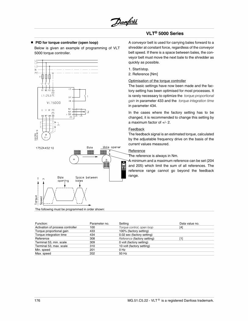
PID for torque controller (open loop)
Below is given an example of programming of VLT5000 torque controller.
A conveyor belt is used for carrying bales forward to ashredder at constant force, regardless of the conveyorbelt speed. If there is a space between bales, the con-veyor belt must move the next bale to the shredder asquickly as possible.
1. Start/stop.2. Reference [Nm]
Optimisation of the torque controllerThe basic settings have now been made and the fac-tory setting has been optimised for most processes. Itis rarely necessary to optimize the torque proportionalgain in parameter 433 and the torque integration timein parameter 434.
In the cases where the factory setting has to bechanged, it is recommended to change this setting bya maximum factor of +/- 2.
FeedbackThe feedback signal is an estimated torque, calculatedby the adjustable frequency drive on the basis of thecurrent values measured.
ReferenceThe reference is always in Nm.A minimum and a maximum reference can be set (204and 205) which limit the sum of all references. Thereference range cannot go beyond the feedbackrange.
The following must be programmed in order shown:
Function: Parameter no. Setting Data value no.Activation of process controller 100 Torque control, open loop [4]Torque proportional gain 433 100% (factory setting)Torque integration time 434 0.02 sec (factory setting)Reference 308 Reference (factory setting) [1]Terminal 53, min. scale 309 0 volt (factory setting)Terminal 53, max. scale 310 10 volt (factory setting)Min. speed 201 0 HzMax. speed 202 50 Hz
VLT® 5000 Series
176 MG.51.C5.22 - VLT is a registered Danfoss trademark.
CE labelling
What is CE labelling?The purpose of CE labelling is to avoid technical ob-stacles to trade within EFTA and the EU. The EU hasintroduced the CE label as a simple way of showingwhether a product complies with the relevant EU di-rectives. The CE label says nothing about the specifi-cations or quality of the product. Adjustable frequencydrives are regulated by three EU directives:•The machinery directive (98/37/EEC)All machines with critical moving parts are covered bythe machinery directive, which came into force on 1January 1995. Since an adjustable frequency drive islargely electrical, it does not fall under the machinerydirective. However, if an adjustable frequency drive issupplied for use in a machine, we provide informationon safety aspects relating to the adjustable frequencydrive. We do this by means of a manufacturer's dec-laration.•The low-voltage directive (73/23/EEC)Adjustable frequency drives must be CE labelled inaccordance with the low-voltage directive, which cameinto force on 1 January 1997. The directive applies toall electrical equipment and appliances used in the 50- 1000 Volt AC and the 75 - 1500 Volt DC voltageranges. Danfoss CE labels in accordance with the di-rective and issues a declaration of conformity uponrequest.•The EMC directive (89/336/EEC)EMC is short for electromagnetic compatibility. Thepresence of electromagnetic compatibility means thatthe mutual interference between different compo-nents/appliances is so small that the functioning of theappliances is not affected.The EMC directive came into force on 1 January 1996.Danfoss CE labels in accordance with the directiveand issues a declaration of conformity upon request.In order that EMC-correct installation can be carriedout, this manual gives detailed instructions for instal-lation. In addition, we specify the standards which ourdifferent products comply with. We offer the filters thatcan be seen from the specifications and provide othertypes of assistance to ensure the optimum EMC result.
In the great majority of cases, the adjustable frequencydrive is used by professionals of the trade as a com-plex component forming part of a larger appliance,system or installation. It must be noted that the re-sponsibility for the final EMC properties of the appli-ance, system or installation rests with the installer.
Danfoss VLT adjustable frequency drive and CElabeling
CE labelling is a positive feature when used for itsoriginal purpose, i.e. to facilitate trade within the EUand EFTA.
However, CE labelling may cover many different spec-ifications. This means that is has to be checked whata given CE label specifically covers.
The specifications covered can in fact be widely dif-ferent. That is why a CE label can give the installer afalse feeling of security when using an adjustable fre-quency drive as a component in a system or an appli-ance.
We CE label our adjustable frequency drives in ac-cordance with the low-voltage directive. This meansthat as long as the adjustable frequency drive is in-stalled correctly, we guarantee that it complies with thelow-voltage directive. We issue a declaration of con-formity that confirms our CE labelling in accordancewith the low-voltage directive.
The CE label also applies to the EMC directive, oncondition that the instructions given in these OperatingInstructions for EMC-correct installation and filteringhave been followed. On this basis, a declaration ofconformity in accordance with the EMC directive is is-sued.
The Operating Instructions give detailed instructionsfor installation to ensure that your installation is EMC-correct. Furthermore, we specify which norms that arecomplied with by our different products.
We offer the filters that can be seen from the specifi-cations and gladly provide other types of assistancethat can help you obtain the best EMC result.
Compliance with EMC directive 89/336/EEC
In the great majority of cases, the VLT adjustable fre-quency drive is used by professionals of the trade asa complex component forming part of a larger appli-ance, system or installation. It must be noted that theresponsibility for the final EMC properties of the appli-ance, system or installation rests with the installer. Asan aid to the installer, Danfoss has prepared EMC in-stallation guidelines for the Power Drive System. The
VLT® 5000 Series
MG.51.C5.22 - VLT is a registered Danfoss trademark. 177
EC
/EM
C
standards and test levels stated for Power Drive Sys-tems are complied with, provided the right EMC-cor-rect instructions for installation have been followed,see electrical installation.
VLT® 5000 Series
178 MG.51.C5.22 - VLT is a registered Danfoss trademark.
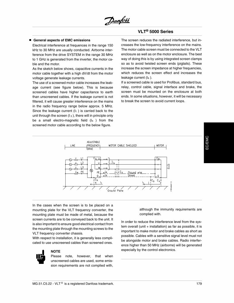
General aspects of EMC emissions
Electrical interference at frequences in the range 150kHz to 30 MHz are usually conducted. Airborne inter-ference from the drive SYSTEM in the range 30 MHzto 1 GHz is generated from the inverter, the motor ca-ble and the motor.As the sketch below shows, capacitive currents in themotor cable together with a high dV/dt from the motorvoltage generate leakage currents.The use of a screened motor cable increases the leak-age current (see figure below). This is becausescreened cables have higher capacitance to earththan unscreened cables. If the leakage current is notfiltered, it will cause greater interference on the mainsin the radio frequency range below approx. 5 MHz.Since the leakage current (I1 ) is carried back to theunit through the screen (I 3 ), there will in principle onlybe a small electro-magnetic field (I4 ) from thescreened motor cable according to the below figure.
The screen reduces the radiated interference, but in-creases the low-frequency interference on the mains.The motor cable screen must be connected to the VLTenclosure as well as on the motor enclosure. The bestway of doing this is by using integrated screen clampsso as to avoid twisted screen ends (pigtails). Theseincrease the screen impedance at higher frequencies,which reduces the screen effect and increases theleakage current (I4 ).If a screened cable is used for Profibus, standard bus,relay, control cable, signal interface and brake, thescreen must be mounted on the enclosure at bothends. In some situations, however, it will be necessaryto break the screen to avoid current loops.
In the cases when the screen is to be placed on amounting plate for the VLT frequency converter, themounting plate must be made of metal, because thescreen currents are to be conveyed back to the unit. Itis also important to ensure good electrical contact fromthe mounting plate through the mounting screws to theVLT frequency converter chassis.With respect to installation, it is generally less compli-cated to use unscreened cables than screened ones.
NOTEPlease note, however, that whenunscreened cables are used, some emis-sion requirements are not complied with,
although the immunity requirements arecomplied with.
In order to reduce the interference level from the sys-tem overall (unit + installation) as far as possible, it isimportant to make motor and brake cables as short aspossible. Cables with a sensitive signal level must notbe alongside motor and brake cables. Radio interfer-ence higher than 50 MHz (airborne) will be generatedespecially by the control electronics.
VLT® 5000 Series
MG.51.C5.22 - VLT is a registered Danfoss trademark. 179
EC
/EM
C
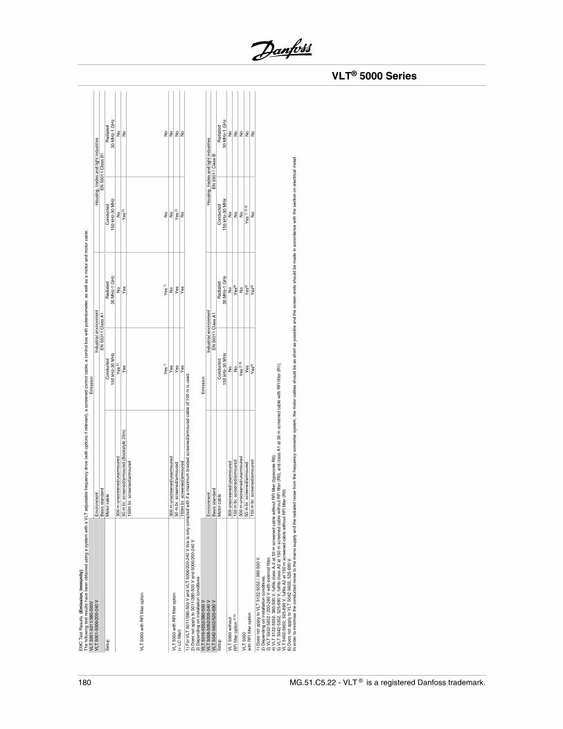
EM
C T
est R
esul
ts (
Em
issi
on
, Im
mu
nit
y)T
he fo
llow
ing
test
res
ults
hav
e be
en o
btai
ned
usin
g a
syst
em w
ith a
VLT
adj
usta
ble
freq
uenc
y dr
ive
(with
opt
ions
if r
elev
ant)
, a s
cree
ned
cont
rol c
able
, a c
ontr
ol b
ox w
ith p
oten
tiom
eter
, as
wel
l as
a m
otor
and
mot
or c
able
.V
LT 5
001-
5011
/380
-500
VE
mis
sion
V
LT 5
001-
5006
/200
-240
VE
nviro
nmen
tIn
dust
rial e
nviro
nmen
tH
ousi
ng, t
rade
s an
d lig
ht in
dust
ries
Bas
ic s
tand
ard
EN
550
11 C
lass
A1
EN
550
11 C
lass
B1
Set
upM
otor
cab
leC
ondu
cted
150
kHz-
30 M
Hz
Rad
iate
d30
MH
z-1
GH
zC
ondu
cted
150
kHz-
30 M
Hz
Rad
iate
d30
MH
z-1
GH
z
VLT
500
0 w
ith R
FI f
ilter
opt
ion
300
m u
nscr
eene
d/un
arm
oure
dY
es 3
)N
oN
oN
o50
m b
r. s
cree
ned/
arm
oure
d (B
ooks
tyle
20m
)Y
esY
esY
es 2
)N
o15
0m b
r. s
cree
ned/
arm
oure
d
Yes
1)
Yes
1)
No
No
VLT
500
0 w
ith R
FI f
ilter
opt
ion
(+ L
C fi
lter)
300
m u
nscr
eene
d/un
arm
oure
dY
esN
oN
oN
o50
m b
r. s
cree
ned/
arm
oure
dY
esY
esY
es 2
)N
o15
0m b
r. s
cree
ned/
arm
oure
dY
esY
esN
oN
o1)
For
VLT
501
1/38
0-50
0 V
and
VLT
500
6/20
0-24
0 V
this
is o
nly
com
plie
d w
ith if
a m
axim
um b
raid
ed s
cree
ned/
arm
oure
d ca
ble
of 1
00 m
is u
sed.
2) D
oes
not a
pply
to 5
011/
380-
500
V a
nd 5
006/
200-
240
V3)
Dep
endi
ng o
n in
stal
latio
n co
nditi
ons
VLT
501
6-55
52/3
80-5
00 V
Em
issi
onV
LT 5
008-
5052
/200
-240
VE
nviro
nmen
tIn
dust
rial e
nviro
nmen
tH
ousi
ng, t
rade
s an
d lig
ht in
dust
ries
VLT
504
2-56
02/5
25-6
90 V
Bas
ic s
tand
ard
EN
550
11 C
lass
A1
EN
550
11 C
lass
BS
etup
Mot
or c
able
Con
duct
ed15
0 kH
z-30
MH
zR
adia
ted
30 M
Hz-
1 G
Hz
Con
duct
ed15
0 kH
z-30
MH
zR
adia
ted
30 M
Hz-
1 G
Hz
VLT
500
0 w
ithou
tR
FI f
ilter
opt
ion
4) 5
)30
0 un
scre
ened
/una
rmou
red
No
No
No
No
150
m b
r. s
cree
ned/
arm
oure
dN
oY
es6)
No
No
VLT
500
0w
ith R
FI f
ilter
opt
ion
300
m u
nscr
eene
d/un
arm
oure
dY
es 2
) 6)
No
No
No
50 m
br.
scr
eene
d/ar
mou
red
Yes
Yes
6)Y
es 1
)3)
6)
No
150
m b
r. s
cree
ned/
arm
oure
dY
es6)
Yes
6)N
oN
o1)
Doe
s no
t app
ly to
VLT
512
2-55
52 /
380-
500
V.
2) D
epen
ding
on
inst
alla
tion
cond
ition
s.3)
VLT
503
2-50
52 /
200-
240
V w
ith e
xter
nal f
ilter
.4)
VLT
512
2-55
52, 3
80-5
00 V
, ful
fils
clas
s A
-2 a
t 50
m s
cree
ned
cabl
e w
ithou
t RF
I filt
er (
type
code
R0)
.5)
VLT
504
2-53
52, 5
25-6
90 V
, ful
fils
clas
s A
2 at
150
m s
cree
ned
cabl
e w
ithou
t RF
I filt
er (
R0)
, and
cla
ss A
1 at
30
m s
cree
ned
cabl
e w
ith R
FI f
ilter
(R
1).
VLT
540
2-56
02, 5
25-6
90 V
, ful
fils
A2
at 1
50 m
scr
eene
d ca
ble
with
out R
FI f
ilter
(R
0)6)
Doe
s no
t app
ly to
VLT
504
2-56
02, 5
25-6
90 V
.In
ord
er to
min
imis
e th
e co
nduc
ted
nois
e to
the
mai
ns s
uppl
y an
d th
e ra
diat
ed n
oise
from
the
freq
uenc
y co
nver
ter
syst
em, t
he m
otor
cab
les
shou
ld b
e as
sho
rt a
s po
ssib
le a
nd th
e sc
reen
end
s sh
ould
be
mad
e in
acc
orda
nce
with
the
sect
ion
on e
lect
rical
inst
all
VLT® 5000 Series
180 MG.51.C5.22 - VLT is a registered Danfoss trademark.
Electrical Installation
Electrical installation - EMC precautions
The following is a guideline to good engineering prac-tice, when installing drives. Following these guidelinesis advised, where compliance with EN 61000-6-3, EN61000-6-4, EN 55011 or EN 61800-3 First environ-ment is required. If the installation is in EN 61800-3Second environment, i.e. industrial networks or in aninstallation that has its own transformer, it is accepta-ble to deviate from these guidelines. It is however notrecommended. See also CE labelling, Emission andEMC test results under special conditions in the DesignGuide for further details.
Good engineering practice to ensure EMC-correctelectrical installation:
• Use only braided screened/armoured motorcables and braided screened/armoured con-trol cables. The screen should provide a min-imum coverage of 80%. The screen materialmust be metal, not limited to but typically cop-per, aluminium, steel or lead. There are nospecial requirements for the mains cable.
• Installations using rigid metal conduits arenot required to use screened cable, but themotor cable must be installed in conduit sep-arate from the control and mains cables. Fullconnection of the conduit from the drive to themotor is required. The EMC performance offlexible conduits varies a lot and informationfrom the manufacturer must be obtained.
• Connect the screen/armour/conduit to earthat both ends for motor cables as well as forcontrol cables. In some cases, it is not pos-sible to connect the screen in both ends. Inthese cases, it is important to connect thescreen at the frequency converter. See alsoEarthing of braided screened/armoured con-trol cables.
• Avoid terminating the screen/armour withtwisted ends (pigtails). Such a termination in-creases the high frequency impedance of the
screen, which reduces its effectiveness athigh frequencies. Use low impedance cableclamps or EMC cable glands instead.
• It is important to ensure good electrical con-tact between the mounting plate on which thefrequency converter is installed and the metalchassis of the frequency converter. However,this does not apply to IP 54 units as they aredesigned for wall-mounting and VLT5122-5552 380-500 V, 5042-5602 525-690 Vand VLT 5032-5052 200-240 V in IP20/NEMA 1 enclosure and IP 54/NEMA 12 en-closure.
• Use starwashers and galvanically conductiveinstallation plates to secure good electricalconnections for IP00 and IP20 installations.
• Avoid using unscreened/unarmoured motoror control cables inside cabinets housing thedrive(s), whenever this can be avoided.
• An uninterrupted high frequency connectionbetween the frequency converter and themotor units is required for IP54 units.
The illustration shows an example of an EMC-correctelectrical installation of an IP 20 frequency converter;the frequency converter has been fitted in an installa-tion cabinet with an output contactor and connected toa PLC, which in this example is installed in a separatecabinet. In IP 54 units and VLT 5032-5052, 200-240 Vin IP20/IP21/NEMA 1 enclosure screened cables areconnected by using EMC conduits to ensure properEMC performance. See illustration. Other ways ofmaking the installation may have as good an EMCperformance, provided the above guide lines to engi-neering practice are followed.
Please note, that when the installation is not carriedthrough according to the guideline as well as whenunscreened cables and control wires are used, someemission requirements are not complied with, al-though the immunity requirements are fulfilled. See thesection EMC test results in the Design Guide for furtherdetails.
VLT® 5000 Series
MG.51.C5.22 - VLT is a registered Danfoss trademark. 181
EC
/EM
C
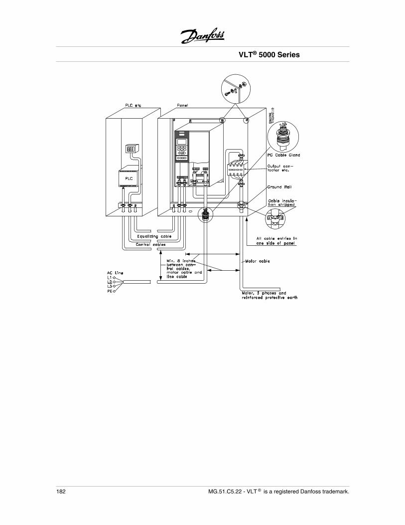
VLT® 5000 Series
182 MG.51.C5.22 - VLT is a registered Danfoss trademark.
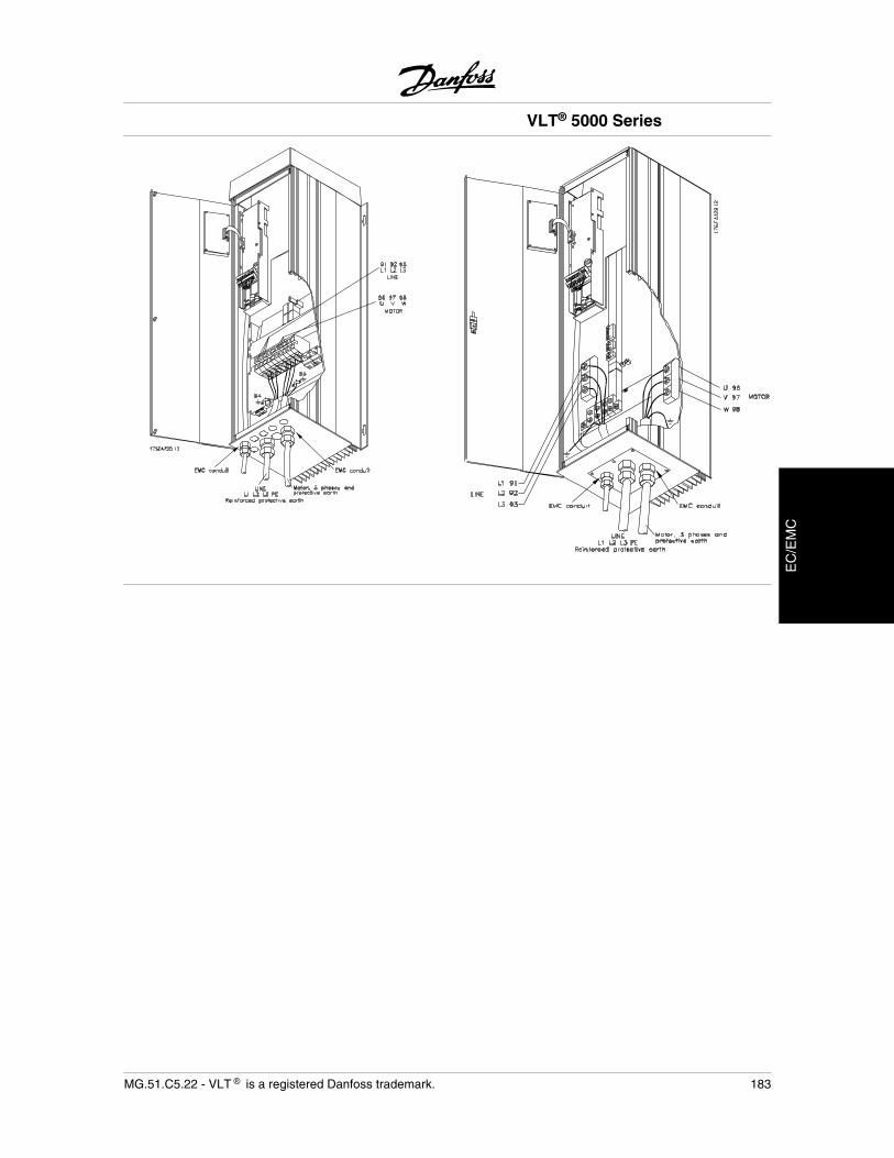
VLT® 5000 Series
MG.51.C5.22 - VLT is a registered Danfoss trademark. 183
EC
/EM
C
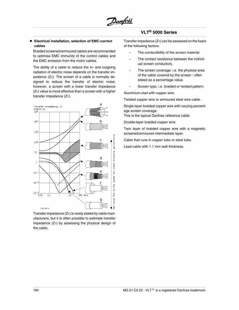
Electrical installation, selection of EMC-correctcables
Braided screened/armoured cables are recommendedto optimise EMC immunity of the control cables andthe EMC emission from the motor cables.
The ability of a cable to reduce the in- and outgoingradiation of electric noise depends on the transfer im-pedance (ZT). The screen of a cable is normally de-signed to reduce the transfer of electric noise;however, a screen with a lower transfer impedance(ZT) value is more effective than a screen with a highertransfer impedance (ZT).
Transfer impedance (ZT) is rarely stated by cable man-ufacturers, but it is often possible to estimate transferimpedance (ZT) by assessing the physical design ofthe cable.
Transfer impedance (ZT) can be assessed on the basisof the following factors:
- The conductibility of the screen material.
- The contact resistance between the individ-ual screen conductors.
- The screen coverage, i.e. the physical areaof the cable covered by the screen - oftenstated as a percentage value.
- Screen type, i.e. braided or twisted pattern.
Aluminium-clad with copper wire.
Twisted copper wire or armoured steel wire cable.
Single-layer braided copper wire with varying percent-age screen coverage.This is the typical Danfoss reference cable.
Double-layer braided copper wire.
Twin layer of braided copper wire with a magnetic,screened/armoured intermediate layer.
Cable that runs in copper tube or steel tube.
Lead cable with 1.1 mm wall thickness.
VLT® 5000 Series
184 MG.51.C5.22 - VLT is a registered Danfoss trademark.
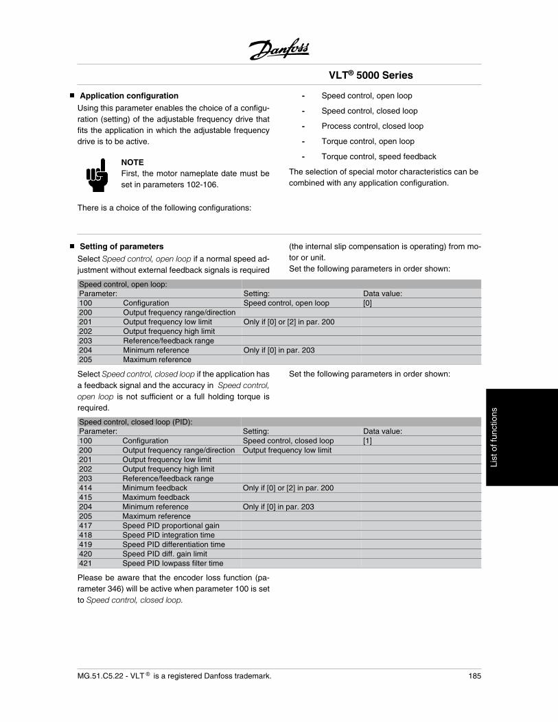
Application configuration
Using this parameter enables the choice of a configu-ration (setting) of the adjustable frequency drive thatfits the application in which the adjustable frequencydrive is to be active.
NOTEFirst, the motor nameplate date must beset in parameters 102-106.
There is a choice of the following configurations:
- Speed control, open loop
- Speed control, closed loop
- Process control, closed loop
- Torque control, open loop
- Torque control, speed feedback
The selection of special motor characteristics can becombined with any application configuration.
Setting of parameters
Select Speed control, open loop if a normal speed ad-justment without external feedback signals is required
(the internal slip compensation is operating) from mo-tor or unit.Set the following parameters in order shown:
Speed control, open loop:Parameter: Setting: Data value:100 Configuration Speed control, open loop [0]200 Output frequency range/direction201 Output frequency low limit Only if [0] or [2] in par. 200202 Output frequency high limit203 Reference/feedback range204 Minimum reference Only if [0] in par. 203205 Maximum reference
Select Speed control, closed loop if the application hasa feedback signal and the accuracy in Speed control,open loop is not sufficient or a full holding torque isrequired.
Set the following parameters in order shown:
Speed control, closed loop (PID):Parameter: Setting: Data value:100 Configuration Speed control, closed loop [1]200 Output frequency range/direction Output frequency low limit201 Output frequency low limit202 Output frequency high limit203 Reference/feedback range414 Minimum feedback Only if [0] or [2] in par. 200415 Maximum feedback204 Minimum reference Only if [0] in par. 203205 Maximum reference417 Speed PID proportional gain418 Speed PID integration time419 Speed PID differentiation time420 Speed PID diff. gain limit421 Speed PID lowpass filter time
Please be aware that the encoder loss function (pa-rameter 346) will be active when parameter 100 is setto Speed control, closed loop.
VLT® 5000 Series
MG.51.C5.22 - VLT is a registered Danfoss trademark. 185
List
of f
unct
ions
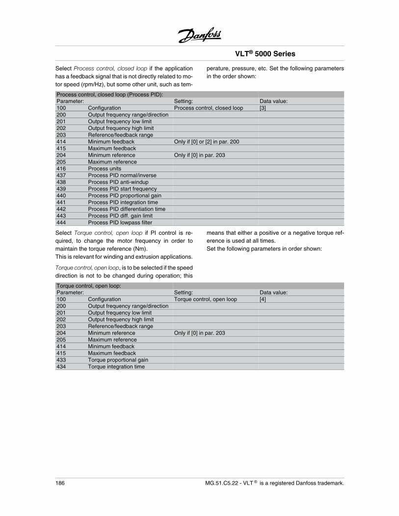
Select Process control, closed loop if the applicationhas a feedback signal that is not directly related to mo-tor speed (rpm/Hz), but some other unit, such as tem-
perature, pressure, etc. Set the following parametersin the order shown:
Process control, closed loop (Process PID):Parameter: Setting: Data value:100 Configuration Process control, closed loop [3]200 Output frequency range/direction201 Output frequency low limit202 Output frequency high limit203 Reference/feedback range414 Minimum feedback Only if [0] or [2] in par. 200415 Maximum feedback204 Minimum reference Only if [0] in par. 203205 Maximum reference416 Process units437 Process PID normal/inverse438 Process PID anti-windup439 Process PID start frequency440 Process PID proportional gain441 Process PID integration time442 Process PID differentiation time443 Process PID diff. gain limit444 Process PID lowpass filter
Select Torque control, open loop if PI control is re-quired, to change the motor frequency in order tomaintain the torque reference (Nm).This is relevant for winding and extrusion applications.
Torque control, open loop, is to be selected if the speeddirection is not to be changed during operation; this
means that either a positive or a negative torque ref-erence is used at all times.Set the following parameters in order shown:
Torque control, open loop:Parameter: Setting: Data value:100 Configuration Torque control, open loop [4]200 Output frequency range/direction201 Output frequency low limit202 Output frequency high limit203 Reference/feedback range204 Minimum reference Only if [0] in par. 203205 Maximum reference414 Minimum feedback415 Maximum feedback433 Torque proportional gain434 Torque integration time
VLT® 5000 Series
186 MG.51.C5.22 - VLT is a registered Danfoss trademark.
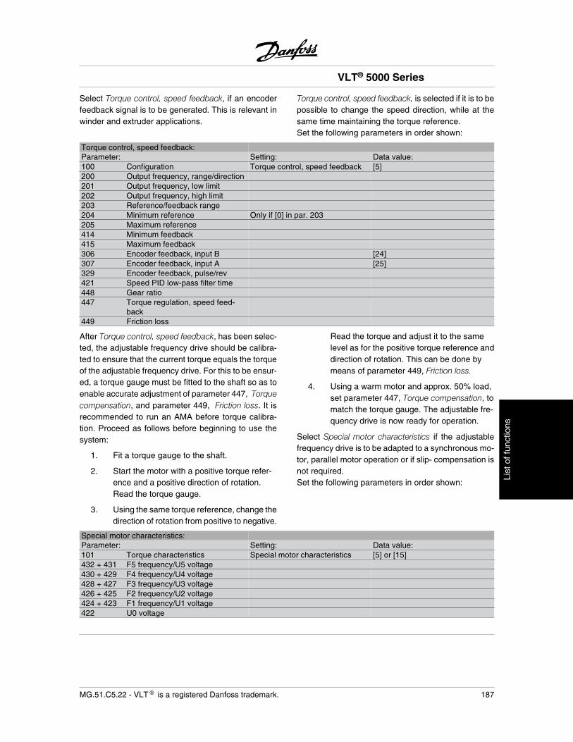
Select Torque control, speed feedback, if an encoderfeedback signal is to be generated. This is relevant inwinder and extruder applications.
Torque control, speed feedback, is selected if it is to bepossible to change the speed direction, while at thesame time maintaining the torque reference.Set the following parameters in order shown:
Torque control, speed feedback:Parameter: Setting: Data value:100 Configuration Torque control, speed feedback [5]200 Output frequency, range/direction201 Output frequency, low limit202 Output frequency, high limit203 Reference/feedback range204 Minimum reference Only if [0] in par. 203205 Maximum reference414 Minimum feedback415 Maximum feedback306 Encoder feedback, input B [24]307 Encoder feedback, input A [25]329 Encoder feedback, pulse/rev421 Speed PID low-pass filter time448 Gear ratio447 Torque regulation, speed feed-
back449 Friction loss
After Torque control, speed feedback, has been selec-ted, the adjustable frequency drive should be calibra-ted to ensure that the current torque equals the torqueof the adjustable frequency drive. For this to be ensur-ed, a torque gauge must be fitted to the shaft so as toenable accurate adjustment of parameter 447, Torquecompensation, and parameter 449, Friction loss. It isrecommended to run an AMA before torque calibra-tion. Proceed as follows before beginning to use thesystem:
1. Fit a torque gauge to the shaft.
2. Start the motor with a positive torque refer-ence and a positive direction of rotation.Read the torque gauge.
3. Using the same torque reference, change thedirection of rotation from positive to negative.
Read the torque and adjust it to the samelevel as for the positive torque reference anddirection of rotation. This can be done bymeans of parameter 449, Friction loss.
4. Using a warm motor and approx. 50% load,set parameter 447, Torque compensation, tomatch the torque gauge. The adjustable fre-quency drive is now ready for operation.
Select Special motor characteristics if the adjustablefrequency drive is to be adapted to a synchronous mo-tor, parallel motor operation or if slip- compensation isnot required.Set the following parameters in order shown:
Special motor characteristics:Parameter: Setting: Data value:101 Torque characteristics Special motor characteristics [5] or [15]432 + 431 F5 frequency/U5 voltage430 + 429 F4 frequency/U4 voltage428 + 427 F3 frequency/U3 voltage426 + 425 F2 frequency/U2 voltage424 + 423 F1 frequency/U1 voltage422 U0 voltage
VLT® 5000 Series
MG.51.C5.22 - VLT is a registered Danfoss trademark. 187
List
of f
unct
ions
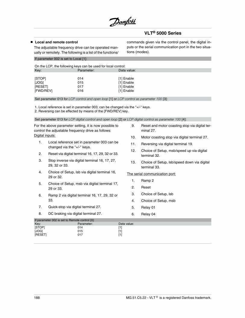
Local and remote control
The adjustable frequency drive can be operated man-ually or remotely. The following is a list of the functions/
commands given via the control panel, the digital in-puts or the serial communication port in the two situa-tions (modes).
If parameter 002 is set to Local [1]:
On the LCP, the following keys can be used for local control:Key: Parameter: Data value: [STOP] 014 [1] Enable[JOG] 015 [1] Enable[RESET] 017 [1] Enable[FWD/REV] 016 [1] Enable Set parameter 013 for LCP control and open loop [1] or LCP control as parameter 100 [3]: 1. Local reference is set in parameter 003; can be changed via the "+/-" keys.2. Reversing can be effected by means of the [FWD/REV] key. Set parameter 013 for LCP digital control and open loop [2] or LCP digital control as parameter 100 [4]:
For the above parameter setting, it is now possible tocontrol the adjustable frequency drive as follows:Digital inputs:
1. Local reference set in parameter 003 can bechanged via the "+/-" keys.
2. Reset via digital terminal 16, 17, 29, 32 or 33.
3. Stop inverse via digital terminal 16, 17, 27,29, 32 or 33.
4. Choice of Setup, lsb via digital terminal 16,29 or 32.
5. Choice of Setup, msb via digital terminal 17,29 or 33.
6. Ramp 2 via digital terminal 16, 17, 29, 32 or33.
7. Quick-stop via digital terminal 27.
8. DC braking via digital terminal 27.
9. Reset and motor coasting stop via digital ter-minal 27.
10. Motor coasting stop via digital terminal 27.
11. Reversing via digital terminal 19.
12. Choice of Setup, msb/speed up via digitalterminal 32.
13. Choice of Setup, lsb/speed down via digitalterminal 33.
The serial communication port:
1. Ramp 2
2. Reset
3. Choice of Setup, lsb
4. Choice of Setup, msb
5. Relay 01
6. Relay 04
If parameter 002 is set to Remote control [0]:Key: Parameter: Data value:[STOP] 014 [1][JOG] 015 [1][RESET] 017 [1]
VLT® 5000 Series
188 MG.51.C5.22 - VLT is a registered Danfoss trademark.
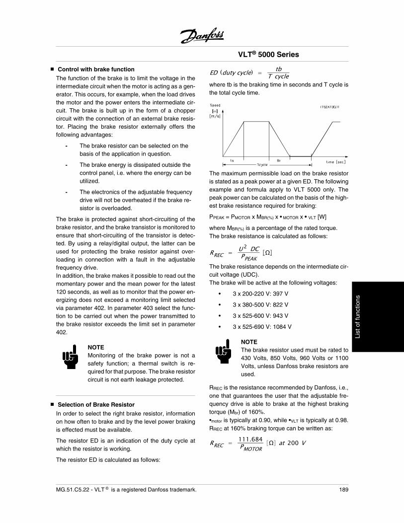
Control with brake function
The function of the brake is to limit the voltage in theintermediate circuit when the motor is acting as a gen-erator. This occurs, for example, when the load drivesthe motor and the power enters the intermediate cir-cuit. The brake is built up in the form of a choppercircuit with the connection of an external brake resis-tor. Placing the brake resistor externally offers thefollowing advantages:
- The brake resistor can be selected on thebasis of the application in question.
- The brake energy is dissipated outside thecontrol panel, i.e. where the energy can beutilized.
- The electronics of the adjustable frequencydrive will not be overheated if the brake re-sistor is overloaded.
The brake is protected against short-circuiting of thebrake resistor, and the brake transistor is monitored toensure that short-circuiting of the transistor is detec-ted. By using a relay/digital output, the latter can beused for protecting the brake resistor against over-loading in connection with a fault in the adjustablefrequency drive.In addition, the brake makes it possible to read out themomentary power and the mean power for the latest120 seconds, as well as to monitor that the power en-ergizing does not exceed a monitoring limit selectedvia parameter 402. In parameter 403 select the func-tion to be carried out when the power transmitted tothe brake resistor exceeds the limit set in parameter402.
NOTEMonitoring of the brake power is not asafety function; a thermal switch is re-quired for that purpose. The brake resistorcircuit is not earth leakage protected.
Selection of Brake Resistor
In order to select the right brake resistor, informationon how often to brake and by the level power brakingis effected must be available.
The resistor ED is an indication of the duty cycle atwhich the resistor is working.
The resistor ED is calculated as follows:
ED (duty cycle) = tbT cycle
where tb is the braking time in seconds and T cycle isthe total cycle time.
The maximum permissible load on the brake resistoris stated as a peak power at a given ED. The followingexample and formula apply to VLT 5000 only. Thepeak power can be calculated on the basis of the high-est brake resistance required for braking:
PPEAK = PMOTOR x MBR(%) x • MOTOR x • VLT [W]
where MBR(%) is a percentage of the rated torque.The brake resistance is calculated as follows:
RREC = U 2 DCPPEAK
The brake resistance depends on the intermediate cir-cuit voltage (UDC).The brake will be active at the following voltages:
• 3 x 200-220 V: 397 V
• 3 x 380-500 V: 822 V
• 3 x 525-600 V: 943 V
• 3 x 525-690 V: 1084 V
NOTEThe brake resistor used must be rated to430 Volts, 850 Volts, 960 Volts or 1100Volts, unless Danfoss brake resistors areused.
RREC is the resistance recommended by Danfoss, i.e.,one that guarantees the user that the adjustable fre-quency drive is able to brake at the highest brakingtorque (Mbr) of 160%.•motor is typically at 0.90, while •VLT is typically at 0.98.RREC at 160% braking torque can be written as:
RREC = 111.684PMOTOR
at 200 V
VLT® 5000 Series
MG.51.C5.22 - VLT is a registered Danfoss trademark. 189
List
of f
unct
ions
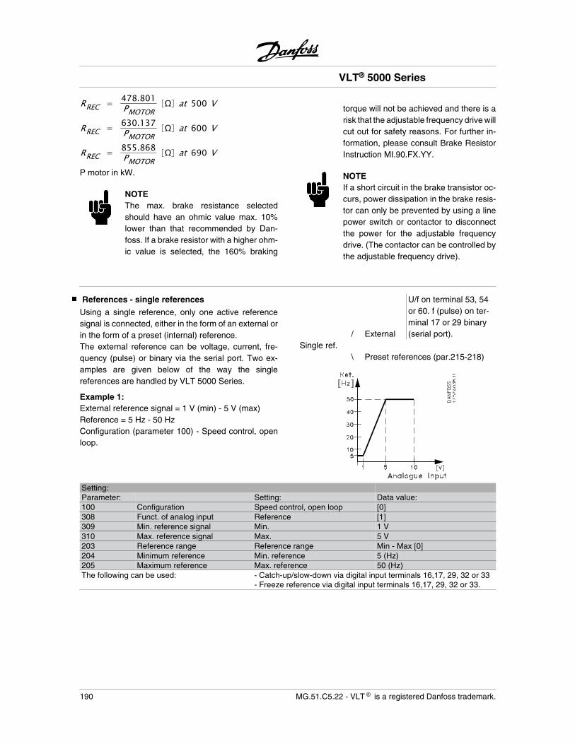
RREC = 478.801PMOTOR
at 500 V
RREC = 630.137PMOTOR
at 600 V
RREC = 855.868PMOTOR
at 690 V
P motor in kW.
NOTEThe max. brake resistance selectedshould have an ohmic value max. 10%lower than that recommended by Dan-foss. If a brake resistor with a higher ohm-ic value is selected, the 160% braking
torque will not be achieved and there is arisk that the adjustable frequency drive willcut out for safety reasons. For further in-formation, please consult Brake ResistorInstruction MI.90.FX.YY.
NOTEIf a short circuit in the brake transistor oc-curs, power dissipation in the brake resis-tor can only be prevented by using a linepower switch or contactor to disconnectthe power for the adjustable frequencydrive. (The contactor can be controlled bythe adjustable frequency drive).
References - single references
Using a single reference, only one active referencesignal is connected, either in the form of an external orin the form of a preset (internal) reference.The external reference can be voltage, current, fre-quency (pulse) or binary via the serial port. Two ex-amples are given below of the way the singlereferences are handled by VLT 5000 Series.
Example 1:External reference signal = 1 V (min) - 5 V (max)Reference = 5 Hz - 50 HzConfiguration (parameter 100) - Speed control, openloop.
U/f on terminal 53, 54or 60. f (pulse) on ter-minal 17 or 29 binary(serial port)./ External
Single ref. \ Preset references (par.215-218)
Setting:Parameter: Setting: Data value:100 Configuration Speed control, open loop [0]308 Funct. of analog input Reference [1]309 Min. reference signal Min. 1 V310 Max. reference signal Max. 5 V203 Reference range Reference range Min - Max [0]204 Minimum reference Min. reference 5 (Hz)205 Maximum reference Max. reference 50 (Hz)The following can be used: - Catch-up/slow-down via digital input terminals 16,17, 29, 32 or 33 - Freeze reference via digital input terminals 16,17, 29, 32 or 33.
VLT® 5000 Series
190 MG.51.C5.22 - VLT is a registered Danfoss trademark.
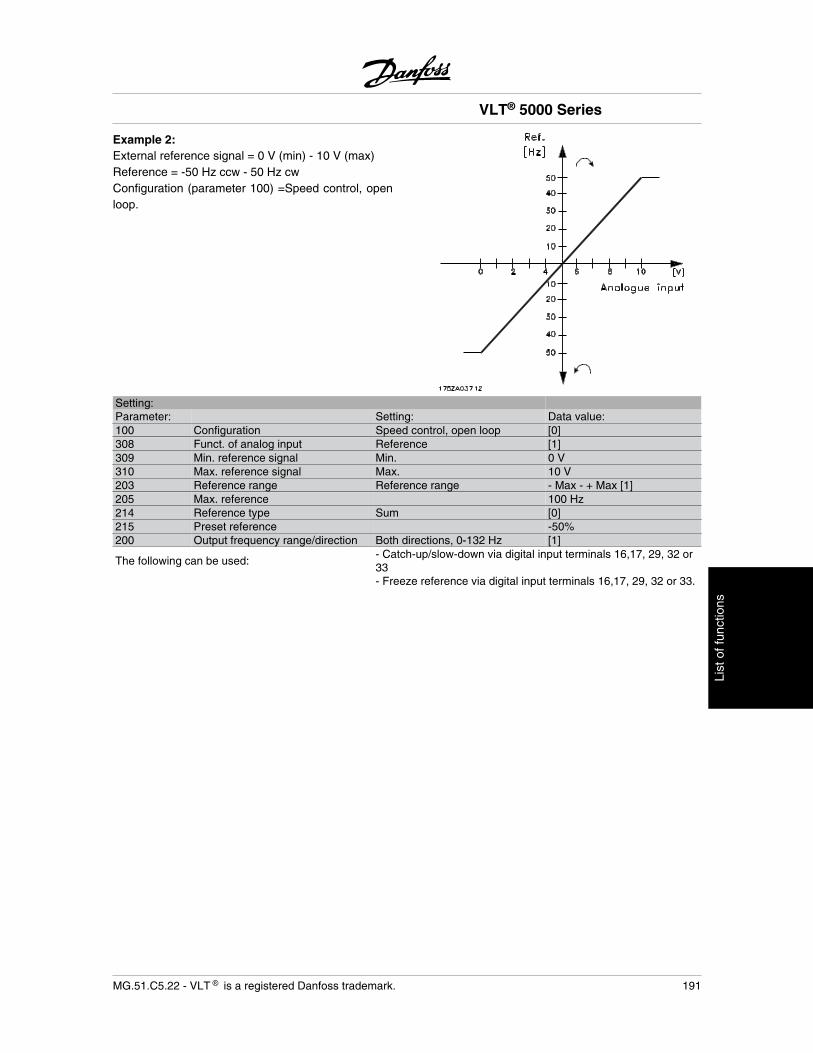
Example 2:External reference signal = 0 V (min) - 10 V (max)Reference = -50 Hz ccw - 50 Hz cwConfiguration (parameter 100) =Speed control, openloop.
Setting:Parameter: Setting: Data value:100 Configuration Speed control, open loop [0]308 Funct. of analog input Reference [1]309 Min. reference signal Min. 0 V310 Max. reference signal Max. 10 V203 Reference range Reference range - Max - + Max [1]205 Max. reference 100 Hz214 Reference type Sum [0]215 Preset reference -50%200 Output frequency range/direction Both directions, 0-132 Hz [1]
The following can be used:- Catch-up/slow-down via digital input terminals 16,17, 29, 32 or33
- Freeze reference via digital input terminals 16,17, 29, 32 or 33.
VLT® 5000 Series
MG.51.C5.22 - VLT is a registered Danfoss trademark. 191
List
of f
unct
ions
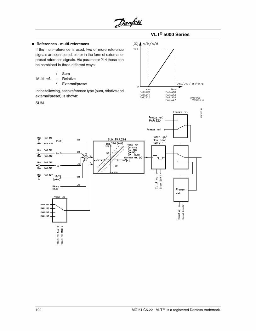
References - multi-references
If the multi-reference is used, two or more referencesignals are connected, either in the form of external orpreset reference signals. Via parameter 214 these canbe combined in three different ways:
/ SumMulti-ref. – Relative \ External/preset
In the following, each reference type (sum, relative andexternal/preset) is shown:
SUM
VLT® 5000 Series
192 MG.51.C5.22 - VLT is a registered Danfoss trademark.
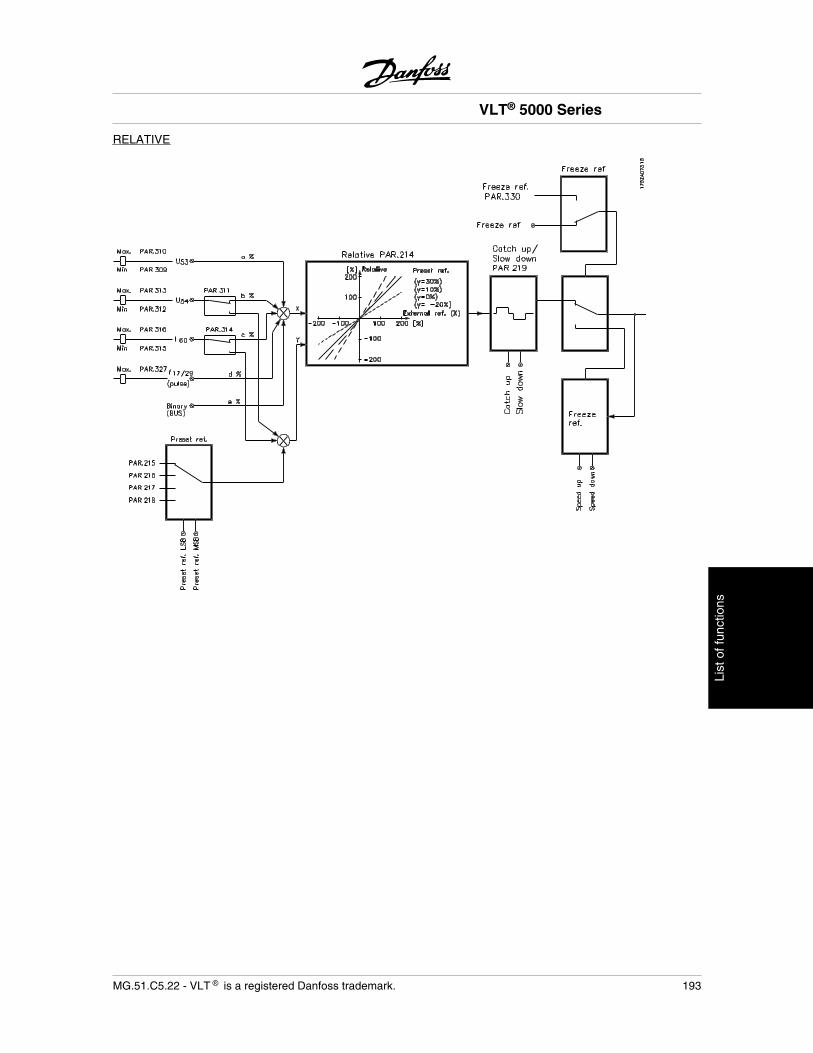
RELATIVE
VLT® 5000 Series
MG.51.C5.22 - VLT is a registered Danfoss trademark. 193
List
of f
unct
ions
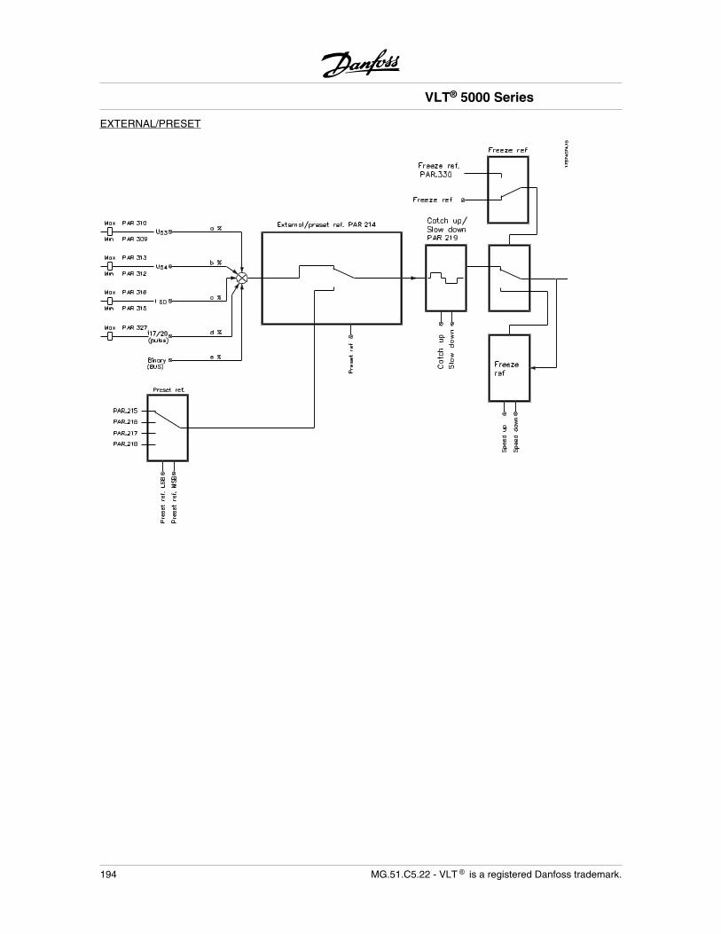
EXTERNAL/PRESET
VLT® 5000 Series
194 MG.51.C5.22 - VLT is a registered Danfoss trademark.
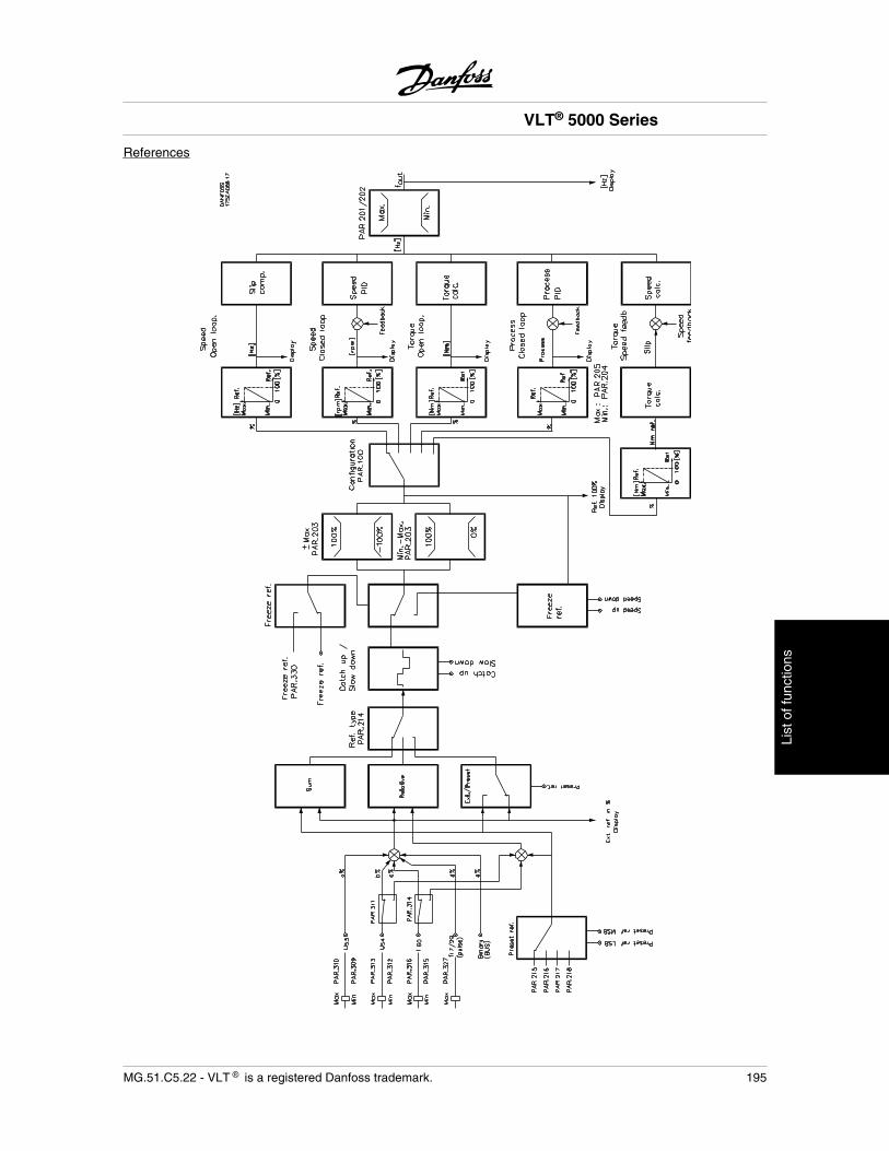
References
VLT® 5000 Series
MG.51.C5.22 - VLT is a registered Danfoss trademark. 195
List
of f
unct
ions
Automatic Motor Adaptation, AMA
Automatic motor adaptation is a test algorithm thatmeasures the electrical motor parameters at a motorstandstill. This means that AMA itself does not supplyany torque.AMA is useful when commissioning systems, wherethe user wants to optimise the adjustment of the fre-quency converter to the motor applied. This feature isused in particular where the factory setting does notadequately cover the motor in question.There are two motor parameters that are of primarysignificance in automatic motor adaptation: the statorresistance, Rs, and the reactance at normal magnet-ising level, Xs. Parameter 107 allows a choice of au-tomatic motor adaptation, with determination of bothRs and Xs, or reduced automatic motor adaptationwith determination of only Rs.The duration of a total automatic motor adaptation var-ies from a few minutes on small motors to more than10 minutes on large motors.
Limitations and preconditions:
• For AMA to be able to determine the motorparameters optimally, the correct nameplatedata for the motor connected to the frequencyconverter must be entered in parameters 102to 106.
• For the best adjustment of the frequency con-verter, it is recommended to carry out AMAon a cold motor. Repeated AMA runs maylead to a heating of the motor that will resultin an increase of the stator resistance, Rs.
• AMA can only be carried out if the rated motorcurrent is minimum 35% of the rated outputcurrent of the frequency converter. AMA canbe carried out up to one oversize motor.
• If a LC filter is inserted between the frequencyconverter and the motor, it will only be pos-sible to carry out a reduced test. If an overallsetting is required, remove the LC filter whilerunning a total AMA. After completion of theAMA reinsert the LC filter.
• If motors are coupled in parallel only use re-duced AMA if any.
• When using synchronous motors it is onlypossible to make a reduced AMA.
• Long motor cables can have an effect on theimplementation of the AMA function if theirresistance is bigger than the stator resistanceof the motor.
How to perform an AMA
1. Press the [STOP/RESET] key
2. Set motor nameplate data in parameters 102to 106
3. Select whether a total [ENABLE (RS,XS)]ora reduced [ENABLE RS] AMA is required inparameter 107
4. Connect terminal 12 (24 VDC) to terminal 27on the control card
5. Press the [START] key or connect terminal18 (start) to terminal 12 (24 VDC) to start theautomatic motor adaptation.
Now the automatic motor adaptation goes through fourtests (for reduced AMA only the first two tests). Thedifferent tests can be followed in the display as dotsafter the text WORKING in parameter 107:
1. Initial error check where nameplate data andphysical errors are checked. Display showsWORKING.
2. DC test where the stator resistance is esti-mated. Display shows WORKING..
3. Transient test where the leakage inductanceis estimated. Display shows WORKING...
4. .AC test where the stator reactance is esti-mated. Display shows WORKING....
NOTEAMA can only be carried out if there areno alarms during tuning.
Discontinue AMA
If the automatic motor adaptation is to be discontinued,press the [STOP/RESET] key or disconnect terminal18 from terminal 12.
The automatic motor adaptation ends up with one ofthe following messages after the test:
VLT® 5000 Series
196 MG.51.C5.22 - VLT is a registered Danfoss trademark.
Warnings and alarm messages
ALARM 21Auto-optimisation OKPress the [STOP/RESET] key or disconnect terminal18 from terminal 12. This alarm indicates that the AMAis OK and that the drive is correctly adapted to the mo-tor.
ALARM 22Auto-optimisation not OK[AUTO MOTOR ADAPT OK]A fault has been found during automatic motor adap-tation. Press the [STOP/RESET] key or disconnectterminal 18 from terminal 12. Check the possiblecause to the fault related to the alarm message given.The figure after the text is the error code, which can beseen in the fault log in parameter 615. Automatic motoradaptation does not update parameters. You maychoose to run a reduced automatic motor adaptation.
CHECK P.103,105 [0][AUTO MOT ADAPT FAIL] Parameter 102, 103 or105 has a wrong setting. Correct the setting and startAMA all over.
LOW P.105 [1]The motor is too small for AMA to be carried out. IfAMA is to be enabled, the rated motor current (param-eter 105) must be higher than 35% of the rated outputcurrent of the frequency converter.
ASYMMETRICAL IMPEDANCE [2]AMA has detected an asymmetrical impedance in themotor connected to the system. The motor could bedefective.
MOTOR TOO BIG [3]The motor connected to the system is too big for AMAto be carried out. The setting in parameter 102 doesnot match the motor used.
MOTOR TOO SMALL [4]The motor connected to the system is too small forAMA to be carried out. The setting in parameter 102does not match the motor used.
TIME OUT [5]AMA fails because of noisy measuring signals. Try tostart AMA all over a number of times, until AMA is car-ried out. Please note that repeated AMA runs may heatthe motor to a level where the stator resistance RS isincreased. In most cases, however, this is not critical.
INTERRUPTED BY USER [6]AMA has been interrupted by the user.
INTERNAL FAULT [7]An internal fault has occurred in the frequency con-verter. Contact your Danfoss supplier.
LIMIT VALUE FAULT [8]The parameter values found for the motor are outsidethe acceptable range within which the frequency con-verter is able to work.
MOTOR ROTATES [9]The motor shaft rotates. Make sure that the load is notable to make the motor shaft rotate. Then start AMAall over.
WARNING 39 - 42A fault have been encountered during automatic motoradaptation. Check the possible fault causes in accord-ance with the warning message. Press the [CHANGEDATA key and select "CONTINUE" if AMA is to con-tinue despite the warning or press the [STOP/RESET]key or disconnect terminal 18 from terminal 12 to dis-continue AMA.
WARNING: 39CHECK P.104,106The setting of parameter 102, 104 or 106 is probablywrong. Check the setting and choose `Continue' or`Stop'.
WARNING: 40CHECK P.103,105The setting of parameter 102, 103 or 105 is probablywrong. Check the setting and choose `Continue' or`Stop'.
WARNING: 41MOTOR TOO BIGThe motor used is probably too big for AMA to be car-ried out. The setting in parameter 102 may not matchthe motor. Check the motor and choose `Continue' or`Stop'.
WARNING: 42MOTOR TOO SMALLThe motor used is probably too small for AMA to becarried out. The setting in parameter 102 may notmatch the motor. Check the motor and choose `Con-tinue' or `Stop'.
VLT® 5000 Series
MG.51.C5.22 - VLT is a registered Danfoss trademark. 197
List
of f
unct
ions
Mechanical brake control
For hoisting applications, it is necessary to be able tocontrol an electro-magnetic brake.For controlling the brake, a relay output (01 or 04) isrequired. This output must be kept closed (voltage-free) during the time when the adjustable frequencydrive is not able to 'hold' the motor, due to a load thatis too large, for example. In parameter 323 or 326 (re-lay outputs 01, 04), select Mechanical brake control[32] or Extended mechanical brake control [34] for ap-plications with an electro-magnetic brake.During start/stop and ramp-down, the output current ismonitored. If Mechanical brake control [32] is selectedand the current is below the level selected in parame-ter 223 Warning: Low current, the mechanical brake isclosed (voltage-free).As a point of departure, a current can be selectedwhich is approx. 70% of the magnetizing current. Pa-rameter 225 Warning: Low frequency states the fre-quency during ramp-down at which the mechanicalbrake is to close again.
If Extended mechanical brake control [34] is selectedthe mechanical brake is closed (voltage-free) during
start until the output current is above the level selectedin parameter 223 Warning: Low Current.During stop mechanical brake is released until the fre-quency is below the level selected in parameter 225Warning: Low frequency.Notice by Extended mechanical brake control [34] thatthe brake does not close if the output current falls un-der parameter 223 Warning: Low current.Nor does a current low level warning appear.
In extended mechanical brake mode, an overcurrenttrip (alarm 13) can be reset by an external reset.
If the adjustable frequency drive is brought into analarm condition or an overcurrent or overvoltage sit-uation, the mechanical brake will immediately cut in.
NOTEThe application shown is only for hoistingwithout counterweight.
Control of mechanical brake:Parameter: Setting: Data value:323 Relay 01 or par. 326 relay 04 Mechanical brake control [32]323 Relay 01 or par. 326 relay 04 Extended mechanical brake control [34]223 Warning: Low current approx. 70% of magnetizing current1)
225 Warning: Low frequency 3-5 Hz 2)
122 Function at stop Pre-magnetization [3]120 Start delay time 0.1-0.3 sec121 Start function Start frequency/voltage clockwise3) [3]130 Start frequency Set to slip frequency
131 Initial voltageThe voltage must correspond to the frequency that has been set in pa-rameter 130.
1. During start and stop, the current limit in pa-rameter 223 determines the switching level.
2. This value indicates the frequency duringramp-down at which the mechanical brake isto be closed again. This assumes that a stopsignal has been given.
3. It must be ensured that the motor starts clock-wise (hoist), since otherwise the adjustablefrequency drive may drop the load. Switch U,V, W connections, if required.
VLT® 5000 Series
198 MG.51.C5.22 - VLT is a registered Danfoss trademark.
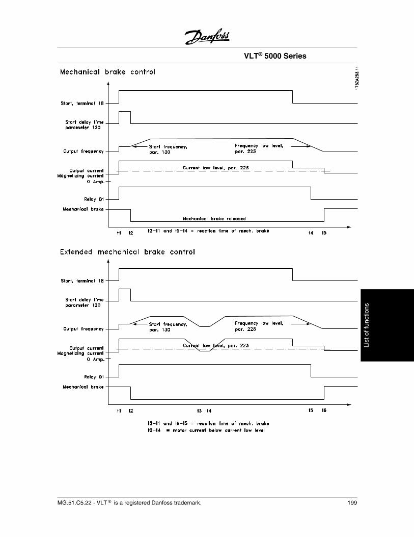
VLT® 5000 Series
MG.51.C5.22 - VLT is a registered Danfoss trademark. 199
List
of f
unct
ions
PID for process control
FeedbackThe feedback signal must be connected to a terminalon the adjustable frequency drive. Use the list belowto decide which terminal is to be used and which pa-rameters are to be programmed.
Feedback type Terminal ParametersPulse 33 307Voltage 53 308, 309, 310Current 60 314, 315, 316
Furthermore, the minimum and maximum feedback(parameters 414 and 415) must be set to a value in theprocess unit that corresponds to the minimum andmaximum value on the terminal.Select process unit in parameter 416.
ReferenceA minimum and a maximum reference can be set (204and 205), which limit the sum of all references. Thereference range cannot exceed the feedback range.If one or several setpoint references are required, thesimplest way is to set such reference directly in pa-rameters 215 to 218. Select between the preset refer-ences by connecting terminals 16, 17, 29, 32 and/or33 to terminal 12. Which terminals that are used de-pends on the choice made in the parameters of thevarious terminals (parameters 300, 301, 305, 306 and/or 307). Use the table below when selecting presetreferences.
Preset ref. msb Preset ref. lsbPreset ref. 1(par. 215)
0 0
Preset ref. 2(par. 216)
0 1
Preset ref. 3(par. 217)
1 0
Preset ref. 4(par. 218)
1 1
If an external reference is required, this can either bean analog or a pulse reference. If current is used as afeedback signal, only voltage can be used as an ana-log reference. Use the following list to decide whichterminal to use and which parameters to program.
Reference type Terminal ParametersPulse 17 or 29 301 or 305Voltage 53 or 54 308, 309, 310 or
311, 312, 313Current 60 314, 315, 316
Relative references can be programmed. A relativereference is a percentage value (Y) of the sum of theexternal references (X). This percentage value is add-ed to the sum of the external references, which pro-duces the active reference (X + XY). See sectionHandling of multi references.If relative references are to be used, parameter 214 isto be set to Relative [1]. This makes the preset refer-ences relative. Furthermore, Relative reference [4] canbe programmed on terminal 54 and/or 60. If an exter-nal relative reference is selected, the signal on theinput will be a percentage value of the full range of theterminal. The relative references are added with signs.
NOTETerminals that are not in use should pref-erably be set to No function [0].
Inverse controlIf the drive has to react with increasing speed on andincreasing feedback, Inverse must be selected in pa-rameter 437. Normal control means that the motorspeed decreases when the feedback signal increases.
Anti WindupThe process controller comes with the anti windupfunction in active position. This function ensures thatwhen either a frequency limit or a torque limit isreached, the integrator will be set to a gain that corre-sponds to the actual frequency. This avoids integratingon an error that cannot in any case be compensatedfor by means of a speed change. This function can bedisabled in parameter 438.
Start-up conditionsIn some applications, optimum setting of the processcontroller will mean that it takes an excessive time forthe desired process value to be reached. In such ap-plications it might be an advantage to fix a motorfrequency to which the adjustable frequency drive is tobring the motor before the process controller is acti-vated. This is done by programming a Process PIDstart frequency in parameter 439.
VLT® 5000 Series
200 MG.51.C5.22 - VLT is a registered Danfoss trademark.
Differentiator gain limitIf there are quick changes in reference or feedback ina given application - which means that the errorchanges swiftly - the differentiator may soon becometoo dominant. This is because it reacts to changes inthe error. The quicker the error changes, the strongerthe differentiator gain is. The differentiator gain canthus be limited to allow setting of the reasonable dif-ferentiation time for slow changes and a suitably quickgain for quick changes. This is done in parameter 443,Process PID Differentiator gain limit.
Lowpass filterIf there are oscillations of the current/voltage feedbacksignal, these can be dampened by means of a lowpassfilter. Set a suitable lowpass filter time constant. Thistime constant represents the limitfrequency of the rip-ples occurring on the feedback signal. If the lowpassfilter has been set to 0.1s, the limit frequency will be10 RAD/sec., corresponding to (10/2 x ) = 1.6 Hz.This will mean that all currents/voltages that vary bymore than 1.6 oscillations per second will be removedby the filter. In other words, control will only be carriedout on a feedback signal that varies by a frequency ofless than 1.6 Hz. Choose a suitable time constant inparameter 444, Process PID Lowpass filter.
Optimisation of the process controllerThe basic settings have now been made; all that needsto be done is to optimise the proportional gain, the in-tegration time and the differentiation time (parameters440, 441, 442). In most processes, this can be doneby following the guidelines given below.
1. Start the motor
2. Set parameter 440 (proportional gain) to 0.3and increase it until the feedback signal againbegins to vary continuously. Then reduce thevalue until the feedback signal has stabilised.Now lower the proportional gain by 40-60%.
3. Set parameter 441 (integration time) to 20sand reduce the value until the feedback sig-nal again begins to vary continuously. In-crease the integration time until the feedbacksignal stabilises, followed by an increase of15-50%.
4. Only use parameter 442 for very fast-actingsystems only (differentiation time). The typi-cal value is four times the set integration time.
The differentiator should only be used whenthe setting of the proportional gain and theintegration time has been fully optimised.
NOTEIf necessary, start/stop can be activated anumber of times in order to provoke a var-iation of the feedback signal.
PID for speed control
FeedbackUse the list below to decide which terminal to use forthe feedback signal and which parameters to program.
Feedback type Terminal ParametersPulse 32 306Pulse 33 307Feedback pulse/rev.
329
Voltage 53 308, 309, 310Current 60 314, 315, 316
Furthermore, the minimum and maximum feedback(parameters 414 and 415) are to be set to values in theprocess unit that correspond to the actual minimumand maximum process feedback values and units. Theminimum feedback cannot be set to a value lower than0. Choose unit in parameter 416.
ReferenceA minimum and a maximum reference can be set (204and 205) which limit the sum of all references. Thereference range cannot exceed the feedback range.If one or several preset references are required, thesimplest way of doing this is by setting such referencesdirectly in parameters 215 to 218. Choose between thepreset references by connecting terminals16,17,29,32 and/or 33 to terminal 12. Which of themthat are to be used depends on the choice in the pa-rameters of the terminals in question (parameters 300,301, 305, 306 and/or 307). The table below can beused to select the preset references.
VLT® 5000 Series
MG.51.C5.22 - VLT is a registered Danfoss trademark. 201
List
of f
unct
ions
Preset ref. msb Preset ref. lsbPreset ref. 1(par. 215)
0 0
Preset ref. 2(par. 216)
0 1
Preset ref. 3(par. 217)
1 0
Preset ref. 4(par. 218)
1 1
If an external reference is required, this can either byan analog reference or a pulse reference. If current isused as a feedback signal, voltage can be used as ananalog reference. Use the list below to decide whichterminal to use and which parameters to program.
Reference type Terminal ParametersPulse 17 or 29 301 or 305Voltage 53 or 54 308, 309, 310 or
311, 312, 313Current 60 314, 315, 316
Relative references can be programmed. A relativereference is a percentage value (Y) of the sum of theexternal references (X). This percentage value is add-ed to the sum of the external references, which pro-duces the active reference (X + XY). See drawing onpages 62 and 63.If relative references are to be used, parameter 214 isto be set to Relative [1]. This makes the preset refer-ences relative. Furthermore, Relative reference [4] canbe programmed on terminal 54 and/or 60. If an exter-nal relative reference is selected, the signal on theinput will be a percentage value of the full range of theterminal. The relative references are added with signs.
NOTETerminals that are not in use should pref-erably be set to No function [0].
Differentiator gain limitIf there are quick changes in reference or feedback ina given application - which means that the errorchanges swiftly - the differentiator may soon becometoo dominant. This is because it reacts to changes inthe error. The quicker the error changes, the strongerthe differentiator gain is. The differentiator gain canthus be limited to allow setting of the reasonable dif-ferentiation time for slow changes and a suitably quickgain for quick changes. This is done in parameter 420,Speed PID Differentiator gain limit.
Lowpass filterIf are oscillations of the current/voltage on the feed-back signal, these can be dampened by means of alowpass filter. Set a suitable lowpass filter time con-stant. This time constant represents the limit frequencyof the ripples occurring on the feedback signal. If thelowpass filter has been set to 0.1s, the break frequencywill be 10 RAD/sec., corresponding to (10/2 x ) = 1.6Hz. This will mean that all currents/voltages that varyby more than 1.6 oscillations per second will be re-moved by the filter.In other words, control will only be carried out on afeedback signal that varies by a frequency of less than1.6 Hz. Choose a suitable time constant in parameter421, Speed PID Lowpass filter.
Quick discharge
This function is only available in EB units (extendedwith brake) of the following type:
• VLT 5001-5052, 200-240 V
• VLT 5001-5102, 380-500 V
• 5001-5062, 525-600 V
This function is used for discharging the capacitors inthe intermediate circuit after the mains supply hasbeen interrupted. This is a useful function for servicingthe adjustable frequency drive and/or the motor instal-lation. The motor must be stopped before quick dis-charge is activated. If the motor acts as a generator,quick discharge is not possible.
The quick discharge function can be selected via pa-rameter 408. The function starts when the intermedi-ate circuit voltage has dropped to a given value andthe rectifier has stopped.In order to obtain the possibility of a quick discharge,the adjustable frequency drive requires an external 24V DC supply to terminals 35 and 36, as well as a suit-able brake resistor on terminals 81 and 82.
For sizing of the discharge resistor for quick discharge,see Brake Instructions MI.50.DX.XX.
NOTEQuick discharge is only possible if the ad-justable frequency drive has 24 Volts ex-ternal DC supply and if an external brake/discharge resistor has been connected.
VLT® 5000 Series
202 MG.51.C5.22 - VLT is a registered Danfoss trademark.
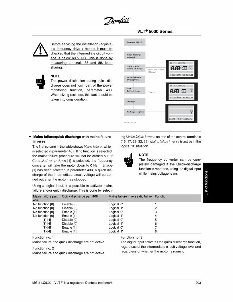
Before servicing the installation (adjusta-ble frequency drive + motor), it must bechecked that the intermediate circuit volt-age is below 60 V DC. This is done bymeasuring terminals 88 and 89, load-sharing.
NOTEThe power dissipation during quick dis-charge does not form part of the powermonitoring function, parameter 403.When sizing resistors, this fact should betaken into consideration.
175ZA447.10
Quick dischargeactivated
Check 24 Voltsexternal DC supply
TRIP (RESET)
Q.DISCHARGING FAILED
No 24 Volts externalDC supply
Q.DISCHARGING FAILED
Timeout
Parameter 408 = [1]
Discharge
Discharge completed
POWER IS DISCHARGED
TRIP (RESET)
ALARM:33
ALARM:33
24 Volts externalDC supply OK
StartQuick discharge
Mains failure/quick discharge with mains failureinverse
The first column in the table shows Mains failure , whichis selected in parameter 407. If no function is selected,the mains failure procedure will not be carried out. IfControlled ramp-down [1] is selected, the frequencyconverter will take the motor down to 0 Hz. If Enable[1] has been selected in parameter 408, a quick dis-charge of the intermediate circuit voltage will be car-ried out after the motor has stopped.
Using a digital input, it is possible to activate mainsfailure and/or quick discharge. This is done by select-
ing Mains failure inverse on one of the control terminals(16, 17, 29, 32, 33). Mains failure inverse is active in thelogical '0' situation.
NOTEThe frequency converter can be com-pletely damaged if the Quick-dischargefunction is repeated, using the digital inputwhile mains voltage is on.
Mains failure par.407
Quick discharge par. 408 Mains failure inverse digital in-put
Function
No function [0] Disable [0] Logical '0' 1No function [0] Disable [0] Logical '1' 2No function [0] Enable [1] Logical '0' 3No function [0] Enable [1] Logical '1' 4
[1]-[4] Disable [0] Logical '0' 5[1]-[4] Disable [0] Logical '1' 6[1]-[4] Enable [1] Logical '0' 7[1]-[4] Enable [1] Logical '1' 8
Function no. 1Mains failure and quick discharge are not active.
Function no. 2Mains failure and quick discharge are not active.
Function no. 3The digital input activates the quick discharge function,regardless of the intermediate circuit voltage level andregardless of whether the motor is running.
VLT® 5000 Series
MG.51.C5.22 - VLT is a registered Danfoss trademark. 203
List
of f
unct
ions
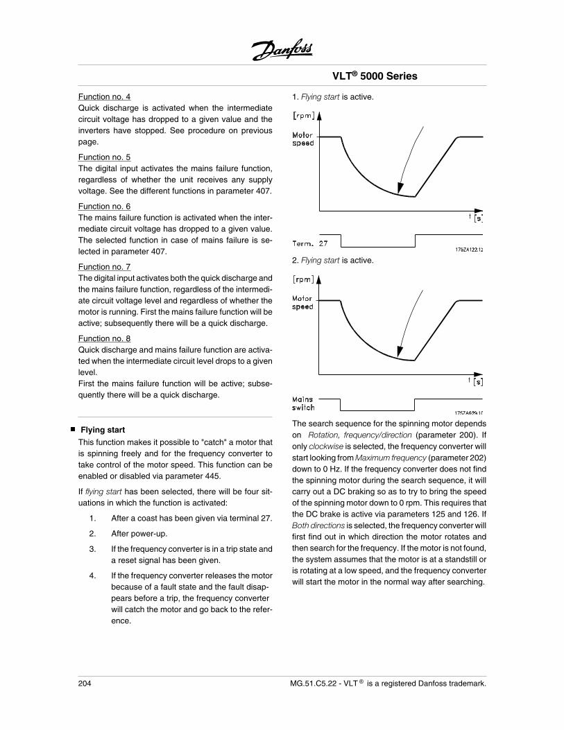
Function no. 4Quick discharge is activated when the intermediatecircuit voltage has dropped to a given value and theinverters have stopped. See procedure on previouspage.
Function no. 5The digital input activates the mains failure function,regardless of whether the unit receives any supplyvoltage. See the different functions in parameter 407.
Function no. 6The mains failure function is activated when the inter-mediate circuit voltage has dropped to a given value.The selected function in case of mains failure is se-lected in parameter 407.
Function no. 7The digital input activates both the quick discharge andthe mains failure function, regardless of the intermedi-ate circuit voltage level and regardless of whether themotor is running. First the mains failure function will beactive; subsequently there will be a quick discharge.
Function no. 8Quick discharge and mains failure function are activa-ted when the intermediate circuit level drops to a givenlevel.First the mains failure function will be active; subse-quently there will be a quick discharge.
Flying start
This function makes it possible to "catch" a motor thatis spinning freely and for the frequency converter totake control of the motor speed. This function can beenabled or disabled via parameter 445.
If flying start has been selected, there will be four sit-uations in which the function is activated:
1. After a coast has been given via terminal 27.
2. After power-up.
3. If the frequency converter is in a trip state anda reset signal has been given.
4. If the frequency converter releases the motorbecause of a fault state and the fault disap-pears before a trip, the frequency converterwill catch the motor and go back to the refer-ence.
1. Flying start is active.
2. Flying start is active.
The search sequence for the spinning motor dependson Rotation, frequency/direction (parameter 200). Ifonly clockwise is selected, the frequency converter willstart looking from Maximum frequency (parameter 202)down to 0 Hz. If the frequency converter does not findthe spinning motor during the search sequence, it willcarry out a DC braking so as to try to bring the speedof the spinning motor down to 0 rpm. This requires thatthe DC brake is active via parameters 125 and 126. IfBoth directions is selected, the frequency converter willfirst find out in which direction the motor rotates andthen search for the frequency. If the motor is not found,the system assumes that the motor is at a standstill oris rotating at a low speed, and the frequency converterwill start the motor in the normal way after searching.
VLT® 5000 Series
204 MG.51.C5.22 - VLT is a registered Danfoss trademark.

3. The frequency converter trips and Flying start is ac-tive.
4. The frequency converter momentarily releases themotor. Flying start is activated and catches the motoragain.
VLT® 5000 Series
MG.51.C5.22 - VLT is a registered Danfoss trademark. 205
List
of f
unct
ions
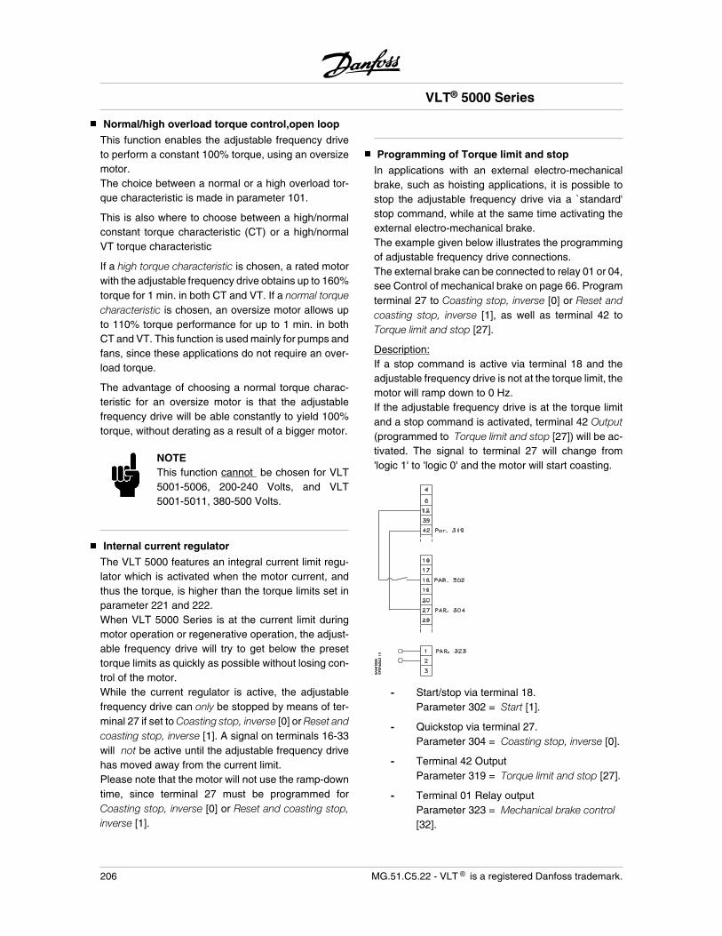
Normal/high overload torque control,open loop
This function enables the adjustable frequency driveto perform a constant 100% torque, using an oversizemotor.The choice between a normal or a high overload tor-que characteristic is made in parameter 101.
This is also where to choose between a high/normalconstant torque characteristic (CT) or a high/normalVT torque characteristic
If a high torque characteristic is chosen, a rated motorwith the adjustable frequency drive obtains up to 160%torque for 1 min. in both CT and VT. If a normal torquecharacteristic is chosen, an oversize motor allows upto 110% torque performance for up to 1 min. in bothCT and VT. This function is used mainly for pumps andfans, since these applications do not require an over-load torque.
The advantage of choosing a normal torque charac-teristic for an oversize motor is that the adjustablefrequency drive will be able constantly to yield 100%torque, without derating as a result of a bigger motor.
NOTEThis function cannot be chosen for VLT5001-5006, 200-240 Volts, and VLT5001-5011, 380-500 Volts.
Internal current regulator
The VLT 5000 features an integral current limit regu-lator which is activated when the motor current, andthus the torque, is higher than the torque limits set inparameter 221 and 222.When VLT 5000 Series is at the current limit duringmotor operation or regenerative operation, the adjust-able frequency drive will try to get below the presettorque limits as quickly as possible without losing con-trol of the motor.While the current regulator is active, the adjustablefrequency drive can only be stopped by means of ter-minal 27 if set to Coasting stop, inverse [0] or Reset andcoasting stop, inverse [1]. A signal on terminals 16-33will not be active until the adjustable frequency drivehas moved away from the current limit.Please note that the motor will not use the ramp-downtime, since terminal 27 must be programmed forCoasting stop, inverse [0] or Reset and coasting stop,inverse [1].
Programming of Torque limit and stop
In applications with an external electro-mechanicalbrake, such as hoisting applications, it is possible tostop the adjustable frequency drive via a `standard'stop command, while at the same time activating theexternal electro-mechanical brake.The example given below illustrates the programmingof adjustable frequency drive connections.The external brake can be connected to relay 01 or 04,see Control of mechanical brake on page 66. Programterminal 27 to Coasting stop, inverse [0] or Reset andcoasting stop, inverse [1], as well as terminal 42 toTorque limit and stop [27].
Description:If a stop command is active via terminal 18 and theadjustable frequency drive is not at the torque limit, themotor will ramp down to 0 Hz.If the adjustable frequency drive is at the torque limitand a stop command is activated, terminal 42 Output(programmed to Torque limit and stop [27]) will be ac-tivated. The signal to terminal 27 will change from'logic 1' to 'logic 0' and the motor will start coasting.
- Start/stop via terminal 18.Parameter 302 = Start [1].
- Quickstop via terminal 27.Parameter 304 = Coasting stop, inverse [0].
- Terminal 42 OutputParameter 319 = Torque limit and stop [27].
- Terminal 01 Relay outputParameter 323 = Mechanical brake control[32].
VLT® 5000 Series
206 MG.51.C5.22 - VLT is a registered Danfoss trademark.
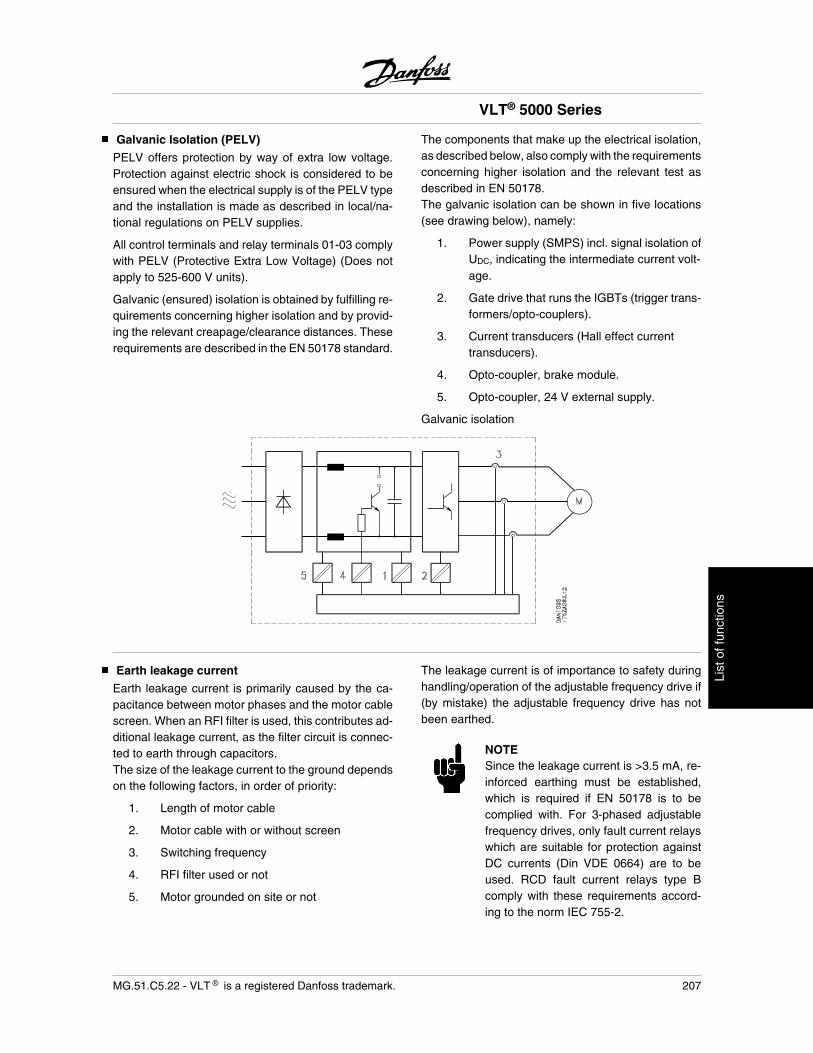
Galvanic Isolation (PELV)
PELV offers protection by way of extra low voltage.Protection against electric shock is considered to beensured when the electrical supply is of the PELV typeand the installation is made as described in local/na-tional regulations on PELV supplies.
All control terminals and relay terminals 01-03 complywith PELV (Protective Extra Low Voltage) (Does notapply to 525-600 V units).
Galvanic (ensured) isolation is obtained by fulfilling re-quirements concerning higher isolation and by provid-ing the relevant creapage/clearance distances. Theserequirements are described in the EN 50178 standard.
The components that make up the electrical isolation,as described below, also comply with the requirementsconcerning higher isolation and the relevant test asdescribed in EN 50178.The galvanic isolation can be shown in five locations(see drawing below), namely:
1. Power supply (SMPS) incl. signal isolation ofUDC, indicating the intermediate current volt-age.
2. Gate drive that runs the IGBTs (trigger trans-formers/opto-couplers).
3. Current transducers (Hall effect currenttransducers).
4. Opto-coupler, brake module.
5. Opto-coupler, 24 V external supply.
Galvanic isolation
Earth leakage current
Earth leakage current is primarily caused by the ca-pacitance between motor phases and the motor cablescreen. When an RFI filter is used, this contributes ad-ditional leakage current, as the filter circuit is connec-ted to earth through capacitors.The size of the leakage current to the ground dependson the following factors, in order of priority:
1. Length of motor cable
2. Motor cable with or without screen
3. Switching frequency
4. RFI filter used or not
5. Motor grounded on site or not
The leakage current is of importance to safety duringhandling/operation of the adjustable frequency drive if(by mistake) the adjustable frequency drive has notbeen earthed.
NOTESince the leakage current is >3.5 mA, re-inforced earthing must be established,which is required if EN 50178 is to becomplied with. For 3-phased adjustablefrequency drives, only fault current relayswhich are suitable for protection againstDC currents (Din VDE 0664) are to beused. RCD fault current relays type Bcomply with these requirements accord-ing to the norm IEC 755-2.
VLT® 5000 Series
MG.51.C5.22 - VLT is a registered Danfoss trademark. 207
List
of f
unct
ions
The following requirements must be complied with:
- Suitable for protecting equipment with a di-rect current content (DC) in the fault current(3-phase rectifier)
- Suitable for power-up with short pulse-sha-ped charging current to earth
- Suitable for a high leakage current.
VLT® 5000 Series
208 MG.51.C5.22 - VLT is a registered Danfoss trademark.
Extreme Running Conditions
Short circuitThe adjustable frequency drive is protected againstshort circuits by means of current measurement ineach of the three motor phases. A short circuit be-tween two output phases will cause an overcurrent inthe inverter. However, each transistor of the inverterwill be turned off individually when the short circuit cur-rent exceeds the permitted value.
After 5-10 s the driver card turns off the inverter andthe adjustable frequency drive will display a fault code,although depending on impedance and motor frequen-cy.
Earth faultThe inverter cuts out within a few s in case of an earthfault on a motor phase, although depending on impe-dance and motor frequency.
Switching on the outputSwitching on the output between the motor and theadjustable frequency drive is fully permitted. It is notpossible to damage VLT 5000 Series in any way byswitching on the output. However, fault messages mayappear.
Motor-generated overvoltageThe voltage in the intermediate circuit is increasedwhen the motor acts as a generator. This occurs in twocases:
1. The load drives the motor (at constant outputfrequency from the adjustable frequencydrive), ie. the load generates energy.
2. During deceleration ("ramp-down") if the mo-ment of inertia is high, the load is low and theramp-down time is too short for the energy tobe dissipated as a loss in the adjustable fre-quency drive, the motor and the installation.
The control unit attempts to correct the ramp if possi-ble.The inverter turns off to protect the transistors and theintermediate circuit capacitors when a certain voltagelevel is reached.
Mains drop-outDuring a mains drop-out, the adjustable frequencydrive continues until the intermediate circuit voltagedrops below the minimum stop level, which is typically15% below the adjustable frequency drive's lowest rat-ed supply voltage.
The time before the inverter stops depends on themains voltage before the drop-out and on the motorload.
Static overloadWhen the adjustable frequency drive is overloaded(the torque limit in parameter 221/222 has beenreached), the controls will reduce the output frequencyin an attempt to reduce the load.If the overload is excessive, a current may occur thatmakes the adjustable frequency drive cut out after ap-prox. 1.5 sec.
Operation within the torque limit can be limited in time(0-60 s) in parameter 409.
VLT® 5000 Series
MG.51.C5.22 - VLT is a registered Danfoss trademark. 209
List
of f
unct
ions
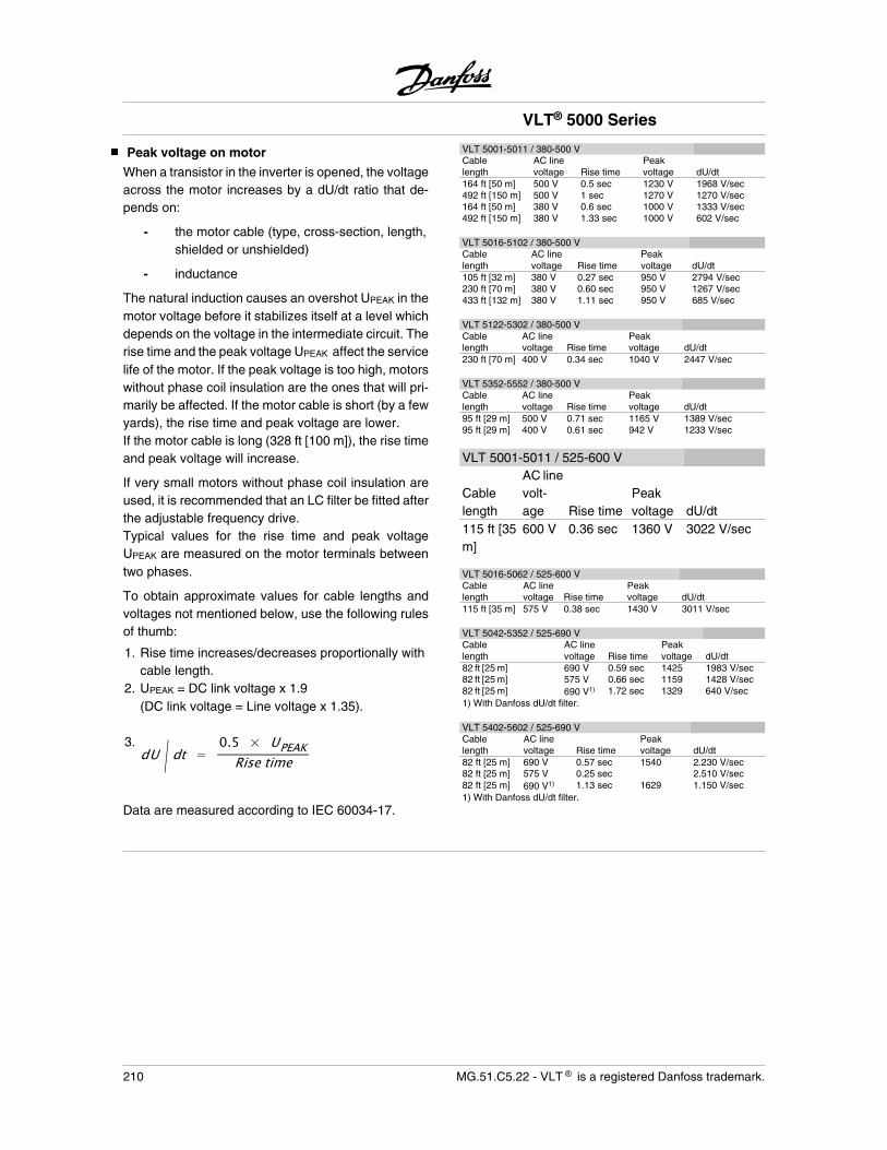
Peak voltage on motor
When a transistor in the inverter is opened, the voltageacross the motor increases by a dU/dt ratio that de-pends on:
- the motor cable (type, cross-section, length,shielded or unshielded)
- inductance
The natural induction causes an overshot UPEAK in themotor voltage before it stabilizes itself at a level whichdepends on the voltage in the intermediate circuit. Therise time and the peak voltage UPEAK affect the servicelife of the motor. If the peak voltage is too high, motorswithout phase coil insulation are the ones that will pri-marily be affected. If the motor cable is short (by a fewyards), the rise time and peak voltage are lower.If the motor cable is long (328 ft [100 m]), the rise timeand peak voltage will increase.
If very small motors without phase coil insulation areused, it is recommended that an LC filter be fitted afterthe adjustable frequency drive.Typical values for the rise time and peak voltageUPEAK are measured on the motor terminals betweentwo phases.
To obtain approximate values for cable lengths andvoltages not mentioned below, use the following rulesof thumb:
1. Rise time increases/decreases proportionally withcable length.
2. UPEAK = DC link voltage x 1.9(DC link voltage = Line voltage x 1.35).
3.dU / dt =
0.5 × UPEAKRise time
Data are measured according to IEC 60034-17.
VLT 5001-5011 / 380-500 VCablelength
AC linevoltage Rise time
Peakvoltage dU/dt
164 ft [50 m] 500 V 0.5 sec 1230 V 1968 V/sec492 ft [150 m] 500 V 1 sec 1270 V 1270 V/sec164 ft [50 m] 380 V 0.6 sec 1000 V 1333 V/sec492 ft [150 m] 380 V 1.33 sec 1000 V 602 V/sec
VLT 5016-5102 / 380-500 VCablelength
AC linevoltage Rise time
Peakvoltage dU/dt
105 ft [32 m] 380 V 0.27 sec 950 V 2794 V/sec230 ft [70 m] 380 V 0.60 sec 950 V 1267 V/sec433 ft [132 m] 380 V 1.11 sec 950 V 685 V/sec
VLT 5122-5302 / 380-500 VCablelength
AC linevoltage Rise time
Peakvoltage dU/dt
230 ft [70 m] 400 V 0.34 sec 1040 V 2447 V/sec
VLT 5352-5552 / 380-500 VCablelength
AC linevoltage Rise time
Peakvoltage dU/dt
95 ft [29 m] 500 V 0.71 sec 1165 V 1389 V/sec95 ft [29 m] 400 V 0.61 sec 942 V 1233 V/sec
VLT 5001-5011 / 525-600 V
Cablelength
AC linevolt-age Rise time
Peakvoltage dU/dt
115 ft [35m]
600 V 0.36 sec 1360 V 3022 V/sec
VLT 5016-5062 / 525-600 VCablelength
AC linevoltage Rise time
Peakvoltage dU/dt
115 ft [35 m] 575 V 0.38 sec 1430 V 3011 V/sec
VLT 5042-5352 / 525-690 VCablelength
AC linevoltage Rise time
Peakvoltage dU/dt
82 ft [25 m] 690 V 0.59 sec 1425 1983 V/sec82 ft [25 m] 575 V 0.66 sec 1159 1428 V/sec82 ft [25 m] 690 V1) 1.72 sec 1329 640 V/sec1) With Danfoss dU/dt filter.
VLT 5402-5602 / 525-690 VCablelength
AC linevoltage Rise time
Peakvoltage dU/dt
82 ft [25 m] 690 V 0.57 sec 1540 2.230 V/sec82 ft [25 m] 575 V 0.25 sec 2.510 V/sec82 ft [25 m] 690 V1) 1.13 sec 1629 1.150 V/sec1) With Danfoss dU/dt filter.
VLT® 5000 Series
210 MG.51.C5.22 - VLT is a registered Danfoss trademark.
Switching on the input
Switching on the input depends on the AC line voltagein question and on whether quick discharge of the in-termediate capacitor has been selected. The tablebelow states the waiting time between cut-ins.
AC line volt-age
380 V 415 V 460 V 500 V 690 V
Withoutquick dis-charge
48 s 65 s 89 s 117 s 120 s
With quickdischarge
74 s 95 s 123 s 158 s
Acoustic noise
The acoustic interference from the adjustable frequen-cy drive comes from two sources:
1. DC intermediate circuit coils.
2. Integral fan.
Below are the typical values measured at a distanceof 1 m from the unit at full load:
VLT 5001-5006 200 - 240 V, VLT 5001-5011 380 -500 VIP 20 / NEMA 1 units:IP 54 / NEMA 12 units:
50 dB(A)62 dB(A)
VLT 5008-5027 200 - 240 V, VLT 5016-5102 380 -500 VIP 20 / NEMA 1 units: 61 dB(A)IP 20 / NEMA 1 unit (VLT5062-5102):
67 dB(A)
IP 54 / NEMA 12 units: 66 dB(A)
VLT 5032-5052 / 200 - 240 VIP 20 / NEMA 1 units: 70 dB(A)IP 54 / NEMA 12 units: 65 dB(A)
VLT 5122-5302 / 380 - 500 VIP 21 / NEMA 1 units: 73 dB(A)IP 54 / NEMA 12 units: 73 dB(A)
VLT 5352 / 380 - 500 VIP 00 and IP 21/ NEMA 1units:
80 dB(A)
IP 54 / NEMA 12 units: 80 dB(A)
VLT 5452-5552 / 380 - 500 VAll enclosure types: 83 dB(A)
VLT 5001-5011 / 525 - 600 VIP 20 / NEMA 1 units: 62 dB(A)
VLT 5016-5062 / 525 - 600 VIP 20 / NEMA 1 units: 66 dB(A)
VLT 5042-5352 / 525 - 690 VIP 21/NEMA 1 units: 74 dB(A)IP 54 units: 74 dB(A)
VLT 5402 / 525 - 690 VAll enclosure types: 80 dB(A)
VLT 5502-5602 / 525 - 690 VAll enclosure types: 83 dB(A)
Measured 1 meter from the unit at full load.
VLT® 5000 Series
MG.51.C5.22 - VLT is a registered Danfoss trademark. 211
List
of f
unct
ions
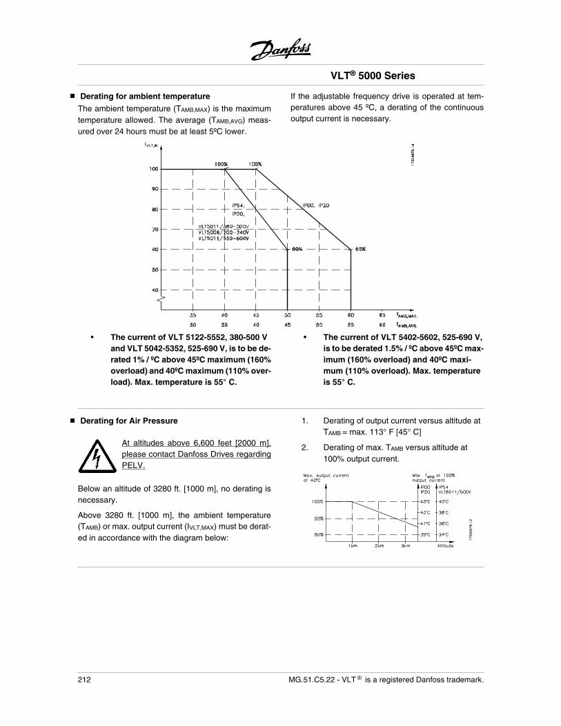
Derating for ambient temperature
The ambient temperature (TAMB,MAX) is the maximumtemperature allowed. The average (TAMB,AVG) meas-ured over 24 hours must be at least 5ºC lower.
If the adjustable frequency drive is operated at tem-peratures above 45 ºC, a derating of the continuousoutput current is necessary.
• The current of VLT 5122-5552, 380-500 Vand VLT 5042-5352, 525-690 V, is to be de-rated 1% / ºC above 45ºC maximum (160%overload) and 40ºC maximum (110% over-load). Max. temperature is 55° C.
• The current of VLT 5402-5602, 525-690 V,is to be derated 1.5% / ºC above 45ºC max-imum (160% overload) and 40ºC maxi-mum (110% overload). Max. temperatureis 55° C.
Derating for Air Pressure
At altitudes above 6,600 feet [2000 m],please contact Danfoss Drives regardingPELV.
Below an altitude of 3280 ft. [1000 m], no derating isnecessary.
Above 3280 ft. [1000 m], the ambient temperature(TAMB) or max. output current (IVLT,MAX) must be derat-ed in accordance with the diagram below:
1. Derating of output current versus altitude atTAMB = max. 113° F [45° C]
2. Derating of max. TAMB versus altitude at100% output current.
VLT® 5000 Series
212 MG.51.C5.22 - VLT is a registered Danfoss trademark.
Derating for Running at Low Speed
When a motor is connected to an adjustable frequencydrive, it is necessary to check whether the cooling ofthe motor is adequate.At low RPM values, the motor fan is not able to supplythe required volume of air for cooling. This problemoccurs when the load torque is constant (e.g. a con-veyor belt) across the regulating range. The reducedventilation available decides the size of the torque thatcan be permitted under a continuous load. If the motoris to run continuously at an RPM value lower than halfthe rated value, the motor must be supplied with addi-tional air for cooling.Instead of such extra cooling, the load level of the mo-tor can be reduced. This can be done by choosing abigger motor. However, the design of the adjustable
frequency drive sets limits as to the size of motor thatcan be connected to it.
Derating for Installing Long Motor Cables or Ca-bles with Larger Cross-section
The adjustable frequency drive has been tested using300 m unscreened cable and 150 m screened cable.
The adjustable frequency drive has been designed towork using a motor cable with a rated cross-section. Ifa cable with a larger cross-section is to be used, it isrecommended to reduce the output current by 5% forevery step the cross-section is increased.(Increased cable cross-section leads to increased ca-pacity to earth, and thus an increased earth leakagecurrent).
Derating for high switching frequency
A higher switching frequency (to be set in parameter411) leads to higher losses in the electronics of theadjustable frequency drive.
If SFAVM has been selected in parameter 446, the ad-justable frequency drive will automatically derate therated output current IVLT,N when the switching frequen-cy exceeds 3.0 kHz.
If 60°AVM is selected, the adjustable frequency drivewill automatically derate when the switching frequencyexceeds 4.5 kHz. In both cases, the reduction is car-ried out linearly, down to 60% of IVLT,N. The table givesthe min., max. and factory-set switching frequenciesfor adjustable frequency drive. The switching patterncan be changed in parameter 446 and the switchingfrequency in parameter 411.
SFAVM 60 deg. AVMMin. [kHz] Max. [kHz] Fac. [kHz] Min. [kHz] Max. [kHz] Fac. [kHz]
VLT 5001-5006, 200 V 3.0 5.0 3.0 3.0 10.0 4.5VLT 5008-5027, 200 V 3.0 10.0 3.0 3.0 14.0 4.5VLT 5032-5052, 200 V 3.0 4.5 3.0 3.0 4.5 4.5VLT 5001-5011, 500 V 3.0 5.0 3.0 3.0 10.0 4.5VLT 5016-5052, 500 V 3.0 10.0 3.0 3.0 14.0 4.5VLT 5062-5102, 500 V 3.0 4.5 3.0 3.0 4.5 4.5VLT 5122-5302, 500 V 3.0 8.0 3.0 2.0 10.0 4.5VLT 5352-5552, 600 V 1.5 2.0 2.0 1.5 3.0 3.0VLT 5001-5011, 600 V 3.0 5.0 3.0 4.5 7.0 4.5VLT 5016-5027, 600 V 3.0 10.0 3.0 3.0 14.0 4.5VLT 5032-5052, 600 V 3.0 7.0 3.0 3.0 10.0 4.5VLT 5062, 600 V 3.0 4.5 3.0 3.0 4.5 4.5VLT 5042-5302, 690 V 1.5 2.0 2.0 1.5 3.0 3.0VLT 5352-5602, 690 V 1.5 1.5 1.5 1.5 2.0 2.0
VLT® 5000 Series
MG.51.C5.22 - VLT is a registered Danfoss trademark. 213
List
of f
unct
ions
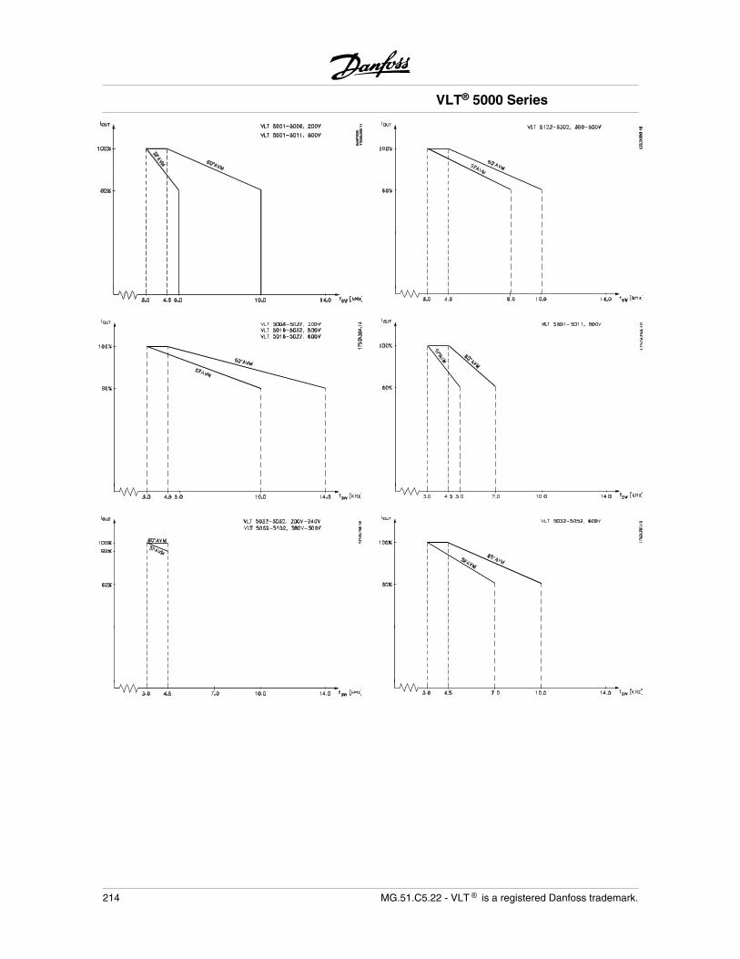
VLT® 5000 Series
214 MG.51.C5.22 - VLT is a registered Danfoss trademark.
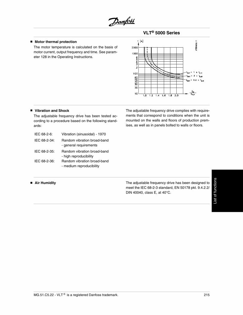
Motor thermal protection
The motor temperature is calculated on the basis ofmotor current, output frequency and time. See param-eter 128 in the Operating Instructions.
Vibration and Shock
The adjustable frequency drive has been tested ac-cording to a procedure based on the following stand-ards:
IEC 68-2-6: Vibration (sinusoidal) - 1970
IEC 68-2-34: Random vibration broad-band- general requirements
IEC 68-2-35: Random vibration broad-band- high reproducibility
IEC 68-2-36: Random vibration broad-band- medium reproducibility
The adjustable frequency drive complies with require-ments that correspond to conditions when the unit ismounted on the walls and floors of production prem-ises, as well as in panels bolted to walls or floors.
Air Humidity The adjustable frequency drive has been designed tomeet the IEC 68-2-3 standard, EN 50178 pkt. 9.4.2.2/DIN 40040, class E, at 40°C.
VLT® 5000 Series
MG.51.C5.22 - VLT is a registered Danfoss trademark. 215
List
of f
unct
ions
Aggressive environments
In common with all electronic equipment, an adjusta-ble frequency drive contains a large number of me-chanical and electronic components, all of which arevulnerable to environmental effects to some extent.
The adjustable frequency drive should nottherefore be installed in environmentswith airborne liquids, particles or gasescapable of affecting and damaging theelectronic components. Failure to take thenecessary protective measures increasesthe risk of stoppages, thus reducing thelife of the adjustable frequency drive.
Liquids can be carried through the air and condensein the adjustable frequency drive. In addition to this,liquids may cause corrosion of components and metalparts. Steam, oil and salt water may cause corrosionof components and metal parts. In such environments,equipment with enclosure rating IP 54 is recommen-ded. As an extra protection, coated printet circuitboads can be orded as an option.
Airborne Particles such as dust particles may causemechanical, electrical or thermal failure in the adjust-able frequency drive. A typical indicator of excessivelevels of airborne particles is dust particles around theadjustable frequency drive fan. In very dusty environ-ments, equipment with enclosure rating IP 54 or acabinet for IP 00/IP 20/Nema 1 equipment is recom-mended.
In environments with high temperatures and humidi-ty, corrosive gases such as sulphur, nitrogen andchlorine compounds will cause chemical processes onthe frequency converter components.
Such chemical reactions will rapidly affect and dam-age the electronic components. In such environments,it is recommended that equipment is mounted in acabinet with fresh air ventilation, keeping aggressivegases away from the frequency converter.An extra protection in such areas a conformal coatingof the printed ircuit boards can be ordered as an option.
NOTEMounting adjustable frequency drives inaggressive environments will increase therisk of stoppages and furthermore consid-erably reduce the life of the drive.
Before the installation of the adjustable frequencydrive, the ambient air should be checked for liquids,particles and gases. This may be done by observingexisting installations in this environment. Typical indi-cators of harmful airborne liquids are water or oil onmetal parts, or corrosion of metal parts.
Excessive dust particle levels are often found on in-stallation cabinets and existing electrical installations.One indicator of aggressive airborne gases is black-ening of copper rails and cable ends on existing in-stallations.
See also Instruction MN.90.IX.YY
VLT® 5000 Series
216 MG.51.C5.22 - VLT is a registered Danfoss trademark.
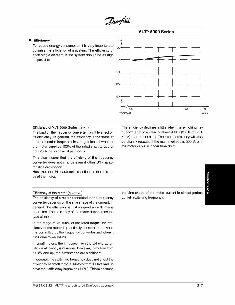
Efficiency
To reduce energy consumption it is very important tooptimize the efficiency of a system. The efficiency ofeach single element in the system should be as highas possible.
Efficiency of VLT 5000 Series ( VLT)The load on the frequency converter has little effect onits efficiency. In general, the efficiency is the same atthe rated motor frequency fM,N, regardless of whetherthe motor supplies 100% of the rated shaft torque oronly 75%, i.e. in case of part loads.
This also means that the efficieny of the frequencyconverter does not change even if other U/f charac-teristics are chosen.However, the U/f characteristics influence the efficien-cy of the motor.
The efficiency declines a little when the switching fre-quency is set to a value of above 4 kHz (3 kHz for VLT5005) (parameter 411). The rate of efficiency will alsobe slightly reduced if the mains voltage is 500 V, or ifthe motor cable is longer than 30 m.
Efficiency of the motor ( MOTOR )The efficiency of a motor connected to the frequencyconverter depends on the sine shape of the current. Ingeneral, the efficiency is just as good as with mainsoperation. The efficiency of the motor depends on thetype of motor.
In the range of 75-100% of the rated torque, the effi-ciency of the motor is practically constant, both whenit is controlled by the frequency converter and when itruns directly on mains.
In small motors, the influence from the U/f character-istic on efficiency is marginal; however, in motors from11 kW and up, the advantages are significant.
In general, the switching frequency does not affect theefficiency of small motors. Motors from 11 kW and uphave their efficiency improved (1-2%). This is because
the sine shape of the motor current is almost perfectat high switching frequency.
VLT® 5000 Series
MG.51.C5.22 - VLT is a registered Danfoss trademark. 217
List
of f
unct
ions
Efficiency of the system ( SYSTEM )To calculate the system efficiency, the efficiency ofVLT 5000 Series ( VLT) is multiplied by the efficiencyof the motor ( MOTOR):
SYSTEM = VLT × MOTOR
Based on the graph on this page, it is possible to cal-culate the efficiency of the system at different loads.
VLT® 5000 Series
218 MG.51.C5.22 - VLT is a registered Danfoss trademark.
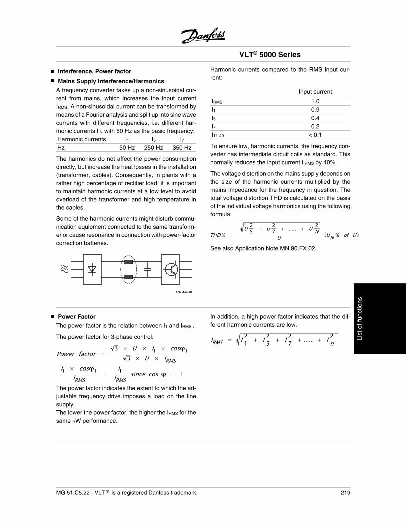
Interference, Power factor
Mains Supply Interference/Harmonics
A frequency converter takes up a non-sinusoidal cur-rent from mains, which increases the input currentIRMS. A non-sinusoidal current can be transformed bymeans of a Fourier analysis and split up into sine wavecurrents with different frequencies, i.e. different har-monic currents I N with 50 Hz as the basic frequency:Harmonic currents I1 I5 I7Hz 50 Hz 250 Hz 350 Hz
The harmonics do not affect the power consumptiondirectly, but increase the heat losses in the installation(transformer, cables). Consequently, in plants with arather high percentage of rectifier load, it is importantto maintain harmonic currents at a low level to avoidoverload of the transformer and high temperature inthe cables.
Some of the harmonic currents might disturb commu-nication equipment connected to the same transform-er or cause resonance in connection with power-factorcorrection batteries.
Harmonic currents compared to the RMS input cur-rent:
Input current
IRMS 1.0I1 0.9I5 0.4I7 0.2I11-49 < 0.1
To ensure low, harmonic currents, the frequency con-verter has intermediate circuit coils as standard. Thisnormally reduces the input current I RMS by 40%.
The voltage distortion on the mains supply depends onthe size of the harmonic currents multiplied by themains impedance for the frequency in question. Thetotal voltage distortion THD is calculated on the basisof the individual voltage harmonics using the followingformula:
THD % =U 25 + U 2
7 + ..... + U 2N
U1(UN % of U )
See also Application Note MN.90.FX.02.
Power Factor
The power factor is the relation between I1 and IRMS .
The power factor for 3-phase control:
Power factor =3 × U × I1 × cos 1
3 × U × IRMSI1 × cos 1
IRMS=
I1IRMS
since cos = 1
The power factor indicates the extent to which the ad-justable frequency drive imposes a load on the linesupply.The lower the power factor, the higher the IRMS for thesame kW performance.
In addition, a high power factor indicates that the dif-ferent harmonic currents are low.
IRMS = I 21 + I 25 + I 27 + ..... + I 2n
VLT® 5000 Series
MG.51.C5.22 - VLT is a registered Danfoss trademark. 219
List
of f
unct
ions
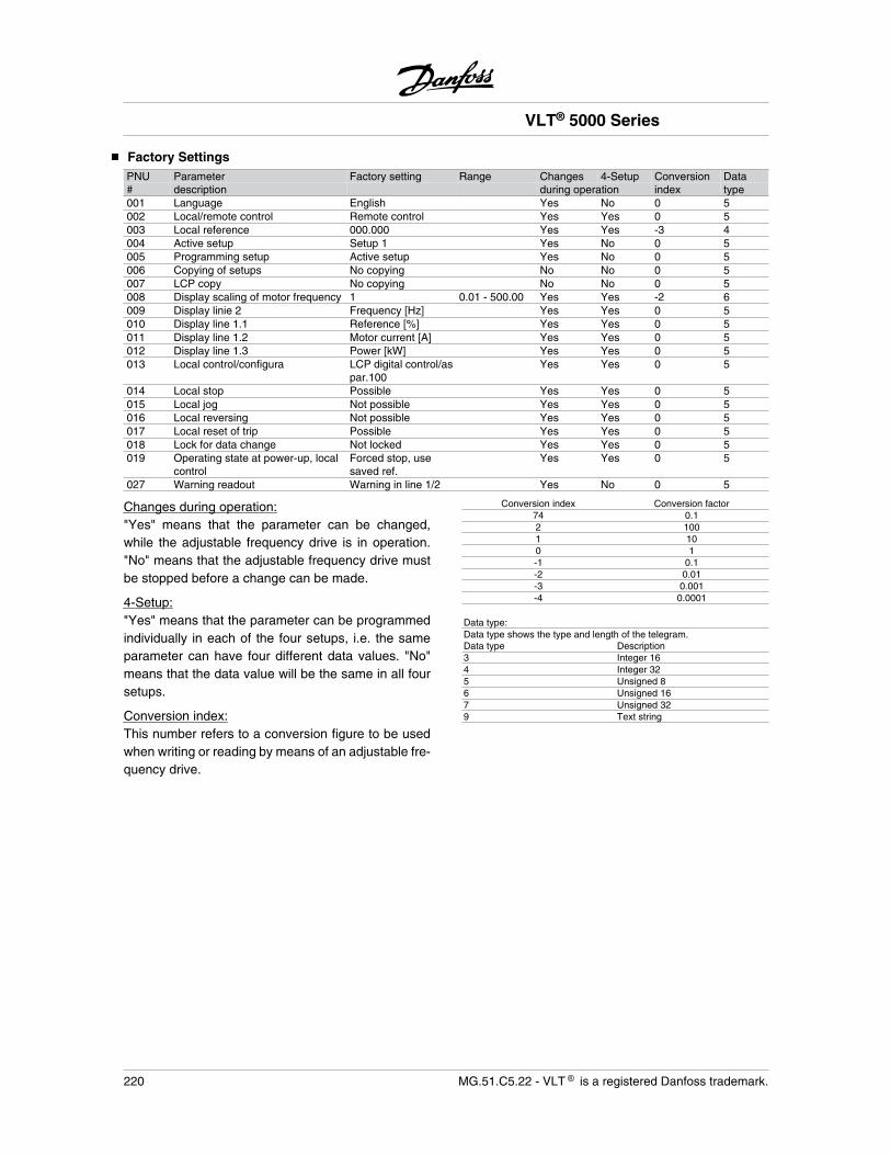
Factory SettingsPNU Parameter Factory setting Range Changes 4-Setup Conversion Data# description during operation index type001 Language English Yes No 0 5002 Local/remote control Remote control Yes Yes 0 5003 Local reference 000.000 Yes Yes -3 4004 Active setup Setup 1 Yes No 0 5005 Programming setup Active setup Yes No 0 5006 Copying of setups No copying No No 0 5007 LCP copy No copying No No 0 5008 Display scaling of motor frequency 1 0.01 - 500.00 Yes Yes -2 6009 Display linie 2 Frequency [Hz] Yes Yes 0 5010 Display line 1.1 Reference [%] Yes Yes 0 5011 Display line 1.2 Motor current [A] Yes Yes 0 5012 Display line 1.3 Power [kW] Yes Yes 0 5013 Local control/configura LCP digital control/as
par.100Yes Yes 0 5
014 Local stop Possible Yes Yes 0 5015 Local jog Not possible Yes Yes 0 5016 Local reversing Not possible Yes Yes 0 5017 Local reset of trip Possible Yes Yes 0 5018 Lock for data change Not locked Yes Yes 0 5019 Operating state at power-up, local
controlForced stop, usesaved ref.
Yes Yes 0 5
027 Warning readout Warning in line 1/2 Yes No 0 5
Changes during operation:"Yes" means that the parameter can be changed,while the adjustable frequency drive is in operation."No" means that the adjustable frequency drive mustbe stopped before a change can be made.
4-Setup:"Yes" means that the parameter can be programmedindividually in each of the four setups, i.e. the sameparameter can have four different data values. "No"means that the data value will be the same in all foursetups.
Conversion index:This number refers to a conversion figure to be usedwhen writing or reading by means of an adjustable fre-quency drive.
Conversion index Conversion factor74 0.12 1001 100 1-1 0.1-2 0.01-3 0.001-4 0.0001
Data type:Data type shows the type and length of the telegram.Data type Description3 Integer 164 Integer 325 Unsigned 86 Unsigned 167 Unsigned 329 Text string
VLT® 5000 Series
220 MG.51.C5.22 - VLT is a registered Danfoss trademark.
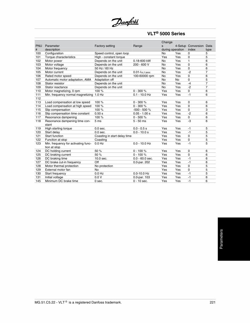
PNU Parameter Factory setting RangeChanges 4-Setup Conversion Data
# description during operation index type100 Configuration Speed control, open loop No Yes 0 5101 Torque characteristics High - constant torque Yes Yes 0 5102 Motor power Depends on the unit 0.18-600 kW No Yes 1 6103 Motor voltage Depends on the unit 200 - 600 V No Yes 0 6104 Motor frequency 50 Hz / 60 Hz No Yes 0 6105 Motor current Depends on the unit 0.01-IVLT,MAX No Yes -2 7106 Rated motor speed Depends on the unit 100-60000 rpm No Yes 0 6107 Automatic motor adaptation, AMA Adaptation off No No 0 5108 Stator resistor Depends on the unit No Yes -4 7109 Stator reactance Depends on the unit No Yes -2 7110 Motor magnetizing, 0 rpm 100 % 0 - 300 % Yes Yes 0 6111 Min. frequency normal magnetizing 1.0 Hz 0.1 - 10.0 Hz Yes Yes -1 6112113 Load compensation at low speed 100 % 0 - 300 % Yes Yes 0 6114 Load compensation at high speed 100 % 0 - 300 % Yes Yes 0 6115 Slip compensation 100 % -500 - 500 % Yes Yes 0 3116 Slip compensation time constant 0.50 s 0.05 - 1.00 s Yes Yes -2 6117 Resonance dampening 100 % 0 - 500 % Yes Yes 0 6118 Resonance dampening time con-
stant5 ms 5 - 50 ms Yes Yes -3 6
119 High starting torque 0.0 sec. 0.0 - 0.5 s Yes Yes -1 5120 Start delay 0.0 sec. 0.0 - 10.0 s Yes Yes -1 5121 Start function Coasting in start delay time Yes Yes 0 5122 Function at stop Coasting Yes Yes 0 5123 Min. frequency for activating func-
tion at stop0.0 Hz 0.0 - 10.0 Hz Yes Yes -1 5
124 DC holding current 50 % 0 - 100 % Yes Yes 0 6125 DC braking current 50 % 0 - 100 % Yes Yes 0 6126 DC braking time 10.0 sec. 0.0 - 60.0 sec. Yes Yes -1 6127 DC brake cut-in frequency Off 0.0-par. 202 Yes Yes -1 6128 Motor thermal protection No protection Yes Yes 0 5129 External motor fan No Yes Yes 0 5130 Start frequency 0.0 Hz 0.0-10.0 Hz Yes Yes -1 5131 Initial voltage 0.0 V 0.0-par. 103 Yes Yes -1 6145 Minimum DC brake time 0 sec. 0 - 10 sec. Yes Yes -1 6
VLT® 5000 Series
MG.51.C5.22 - VLT is a registered Danfoss trademark. 221
Par
amet
ers
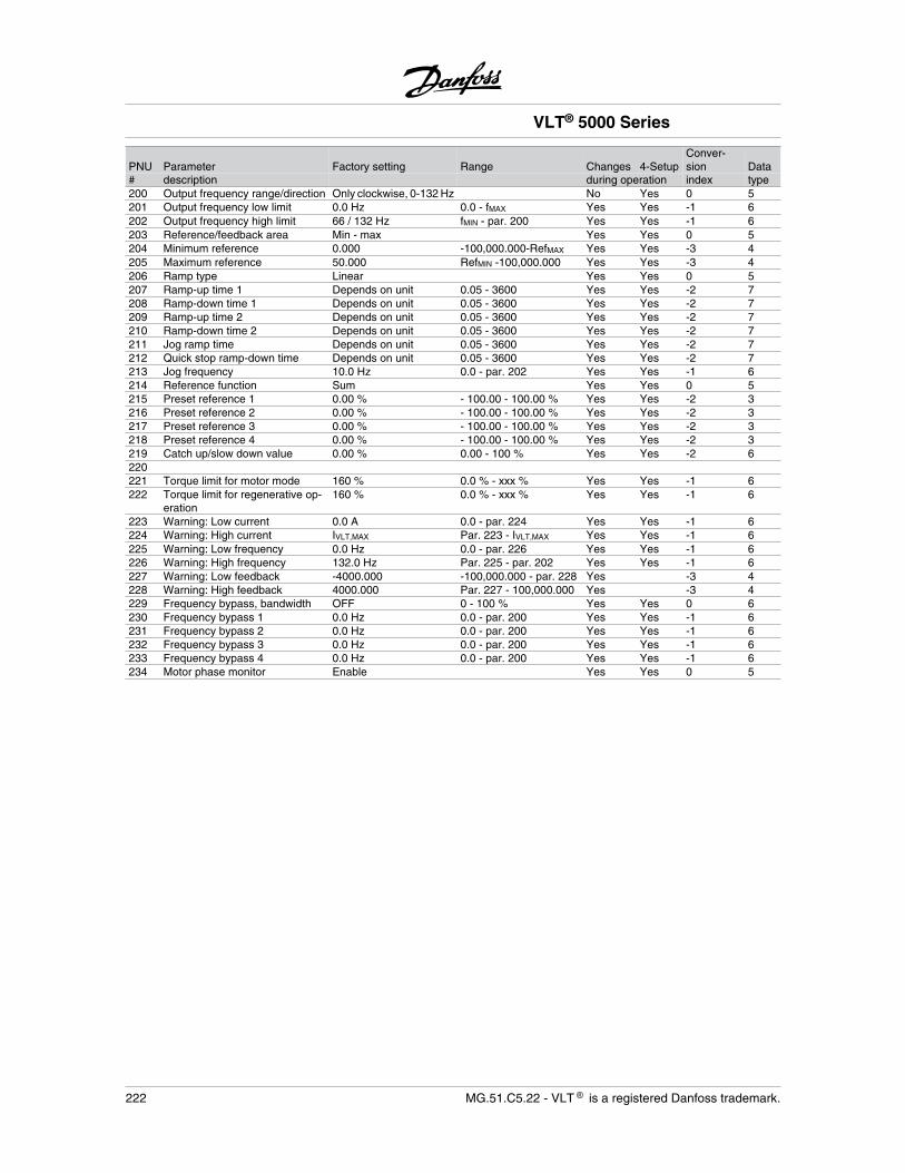
PNU Parameter Factory setting Range Changes 4-SetupConver-sion Data
# description during operation index type200 Output frequency range/direction Only clockwise, 0-132 Hz No Yes 0 5201 Output frequency low limit 0.0 Hz 0.0 - fMAX Yes Yes -1 6202 Output frequency high limit 66 / 132 Hz fMIN - par. 200 Yes Yes -1 6203 Reference/feedback area Min - max Yes Yes 0 5204 Minimum reference 0.000 -100,000.000-RefMAX Yes Yes -3 4205 Maximum reference 50.000 RefMIN -100,000.000 Yes Yes -3 4206 Ramp type Linear Yes Yes 0 5207 Ramp-up time 1 Depends on unit 0.05 - 3600 Yes Yes -2 7208 Ramp-down time 1 Depends on unit 0.05 - 3600 Yes Yes -2 7209 Ramp-up time 2 Depends on unit 0.05 - 3600 Yes Yes -2 7210 Ramp-down time 2 Depends on unit 0.05 - 3600 Yes Yes -2 7211 Jog ramp time Depends on unit 0.05 - 3600 Yes Yes -2 7212 Quick stop ramp-down time Depends on unit 0.05 - 3600 Yes Yes -2 7213 Jog frequency 10.0 Hz 0.0 - par. 202 Yes Yes -1 6214 Reference function Sum Yes Yes 0 5215 Preset reference 1 0.00 % - 100.00 - 100.00 % Yes Yes -2 3216 Preset reference 2 0.00 % - 100.00 - 100.00 % Yes Yes -2 3217 Preset reference 3 0.00 % - 100.00 - 100.00 % Yes Yes -2 3218 Preset reference 4 0.00 % - 100.00 - 100.00 % Yes Yes -2 3219 Catch up/slow down value 0.00 % 0.00 - 100 % Yes Yes -2 6220221 Torque limit for motor mode 160 % 0.0 % - xxx % Yes Yes -1 6222 Torque limit for regenerative op-
eration160 % 0.0 % - xxx % Yes Yes -1 6
223 Warning: Low current 0.0 A 0.0 - par. 224 Yes Yes -1 6224 Warning: High current IVLT,MAX Par. 223 - IVLT,MAX Yes Yes -1 6225 Warning: Low frequency 0.0 Hz 0.0 - par. 226 Yes Yes -1 6226 Warning: High frequency 132.0 Hz Par. 225 - par. 202 Yes Yes -1 6227 Warning: Low feedback -4000.000 -100,000.000 - par. 228 Yes -3 4228 Warning: High feedback 4000.000 Par. 227 - 100,000.000 Yes -3 4229 Frequency bypass, bandwidth OFF 0 - 100 % Yes Yes 0 6230 Frequency bypass 1 0.0 Hz 0.0 - par. 200 Yes Yes -1 6231 Frequency bypass 2 0.0 Hz 0.0 - par. 200 Yes Yes -1 6232 Frequency bypass 3 0.0 Hz 0.0 - par. 200 Yes Yes -1 6233 Frequency bypass 4 0.0 Hz 0.0 - par. 200 Yes Yes -1 6234 Motor phase monitor Enable Yes Yes 0 5
VLT® 5000 Series
222 MG.51.C5.22 - VLT is a registered Danfoss trademark.
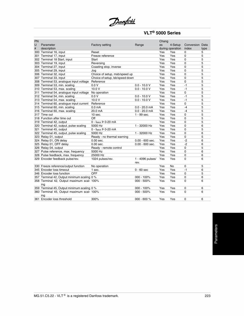
PNU Parameter Factory setting Range
Changes 4-Setup Conversion Data
# description during operation index type300 Terminal 16, input Reset Yes Yes 0 5301 Terminal 17, input Freeze reference Yes Yes 0 5302 Terminal 18 Start, input Start Yes Yes 0 5303 Terminal 19, input Reversing Yes Yes 0 5304 Terminal 27, input Coasting stop, inverse Yes Yes 0 5305 Terminal 29, input Jog Yes Yes 0 5306 Terminal 32, input Choice of setup, msb/speed up Yes Yes 0 5307 Terminal 33, input Choice of setup, lsb/speed down Yes Yes 0 5308 Terminal 53, analogue input voltage Reference Yes Yes 0 5309 Terminal 53, min. scaling 0.0 V 0.0 - 10.0 V Yes Yes -1 5310 Terminal 53, max. scaling 10.0 V 0.0 - 10.0 V Yes Yes -1 5311 Terminal 54, analogue input voltage No operation Yes Yes 0 5312 Terminal 54, min. scaling 0.0 V 0.0 - 10.0 V Yes Yes -1 5313 Terminal 54, max. scaling 10.0 V 0.0 - 10.0 V Yes Yes -1 5314 Terminal 60, analogue input current Reference Yes Yes 0 5315 Terminal 60, min. scaling 0.0 mA 0.0 - 20.0 mA Yes Yes -4 5316 Terminal 60, max. scaling 20.0 mA 0.0 - 20.0 mA Yes Yes -4 5317 Time out 10 sec. 1 - 99 sec. Yes Yes 0 5318 Function after time out Off Yes Yes 0 5319 Terminal 42, output 0 - IMAX Þ 0-20 mA Yes Yes 0 5320 Terminal 42, output, pulse scaling 5000 Hz 1 - 32000 Hz Yes Yes 0 6321 Terminal 45, output 0 - fMAX Þ 0-20 mA Yes Yes 0 5322 Terminal 45, output, pulse scaling 5000 Hz 1 - 32000 Hz Yes Yes 0 6323 Relay 01, output Ready - no thermal warning Yes Yes 0 5324 Relay 01, ON delay 0.00 sec. 0.00 - 600 sec. Yes Yes -2 6325 Relay 01, OFF delay 0.00 sec. 0.00 - 600 sec. Yes Yes -2 6326 Relay 04, output Ready - remote control Yes Yes 0 5327 Pulse reference, max. frequency 5000 Hz Yes Yes 0 6328 Pulse feedback, max. frequency 25000 Hz Yes Yes 0 6329 Encoder feedback pulse/rev. 1024 pulses/rev. 1 - 4096 pulses/
rev.Yes Yes 0 6
330 Freeze reference/output function No operation Yes No 0 5345 Encoder loss timeout 1 sec. 0 - 60 sec Yes Yes -1 6346 Encoder loss function OFF Yes Yes 0 5357 Terminal 42, Output minimum scaling 0 % 000 - 100% Yes Yes 0 6358 Terminal 42, Output maximum scal-
ing100% 000 - 500% Yes Yes 0 6
359 Terminal 45, Output minimum scaling 0 % 000 - 100% Yes Yes 0 6360 Terminal 45, Output maximum scal-
ing100% 000 - 500% Yes Yes 0 6
361 Encoder loss threshold 300% 000 - 600 % Yes Yes 0 6
VLT® 5000 Series
MG.51.C5.22 - VLT is a registered Danfoss trademark. 223
Par
amet
ers
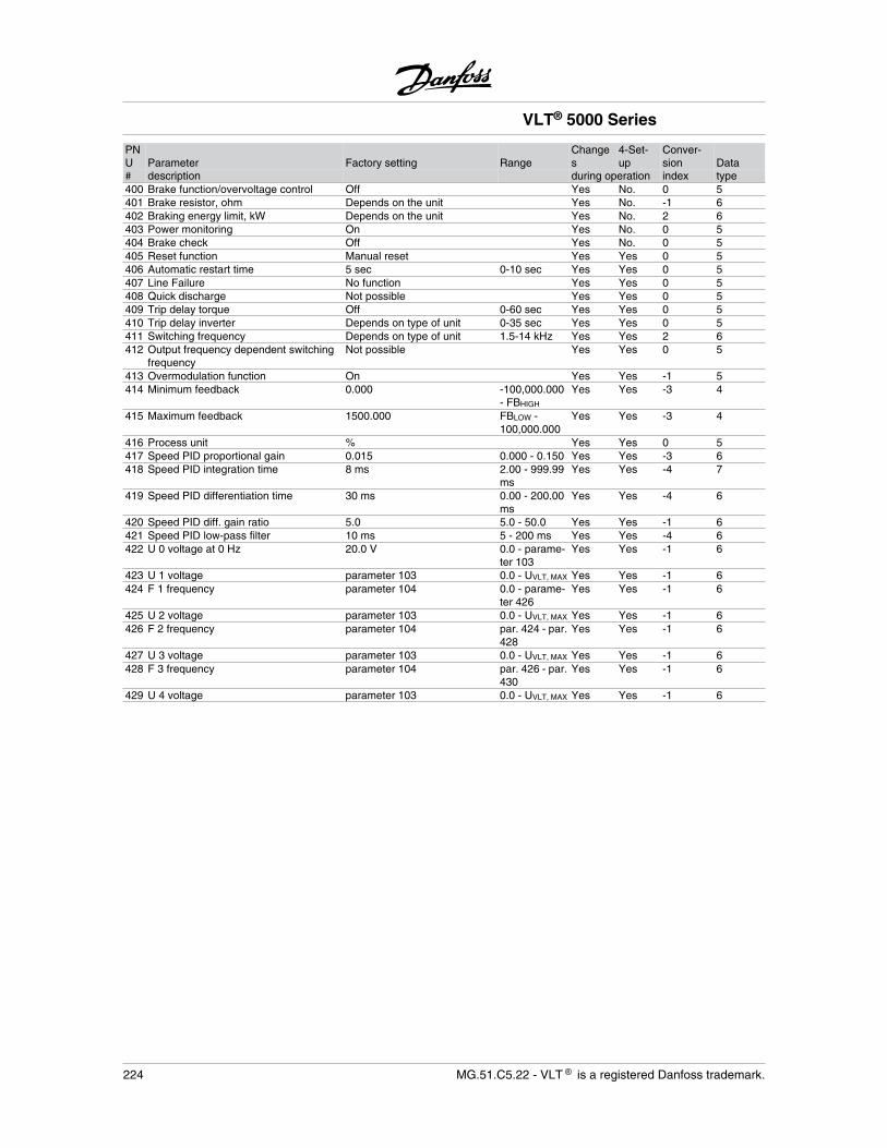
PNU Parameter Factory setting Range
Changes
4-Set-up
Conver-sion Data
# description during operation index type400 Brake function/overvoltage control Off Yes No. 0 5401 Brake resistor, ohm Depends on the unit Yes No. -1 6402 Braking energy limit, kW Depends on the unit Yes No. 2 6403 Power monitoring On Yes No. 0 5404 Brake check Off Yes No. 0 5405 Reset function Manual reset Yes Yes 0 5406 Automatic restart time 5 sec 0-10 sec Yes Yes 0 5407 Line Failure No function Yes Yes 0 5408 Quick discharge Not possible Yes Yes 0 5409 Trip delay torque Off 0-60 sec Yes Yes 0 5410 Trip delay inverter Depends on type of unit 0-35 sec Yes Yes 0 5411 Switching frequency Depends on type of unit 1.5-14 kHz Yes Yes 2 6412 Output frequency dependent switching
frequencyNot possible Yes Yes 0 5
413 Overmodulation function On Yes Yes -1 5414 Minimum feedback 0.000 -100,000.000
- FBHIGH
Yes Yes -3 4
415 Maximum feedback 1500.000 FBLOW -100,000.000
Yes Yes -3 4
416 Process unit % Yes Yes 0 5417 Speed PID proportional gain 0.015 0.000 - 0.150 Yes Yes -3 6418 Speed PID integration time 8 ms 2.00 - 999.99
msYes Yes -4 7
419 Speed PID differentiation time 30 ms 0.00 - 200.00ms
Yes Yes -4 6
420 Speed PID diff. gain ratio 5.0 5.0 - 50.0 Yes Yes -1 6421 Speed PID low-pass filter 10 ms 5 - 200 ms Yes Yes -4 6422 U 0 voltage at 0 Hz 20.0 V 0.0 - parame-
ter 103Yes Yes -1 6
423 U 1 voltage parameter 103 0.0 - UVLT, MAX Yes Yes -1 6424 F 1 frequency parameter 104 0.0 - parame-
ter 426Yes Yes -1 6
425 U 2 voltage parameter 103 0.0 - UVLT, MAX Yes Yes -1 6426 F 2 frequency parameter 104 par. 424 - par.
428Yes Yes -1 6
427 U 3 voltage parameter 103 0.0 - UVLT, MAX Yes Yes -1 6428 F 3 frequency parameter 104 par. 426 - par.
430Yes Yes -1 6
429 U 4 voltage parameter 103 0.0 - UVLT, MAX Yes Yes -1 6
VLT® 5000 Series
224 MG.51.C5.22 - VLT is a registered Danfoss trademark.
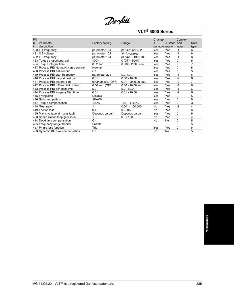
PNU Parameter Factory setting Range
Changes 4-Setup
Conver-sion Data
# description during operation index type430 F 4 frequency parameter 104 par.426-par.432 Yes Yes -1 6431 U 5 voltage parameter 103 .0 - UVLT, MAX Yes Yes -1 6432 F 5 frequency parameter 104 par.426 - 1000 Hz Yes Yes -1 6433 Torque proportional gain 100% 0 (Off) - 500% Yes Yes 0 6434 Torque integral time 0.02 sec. 0.002 - 2.000 sec. Yes Yes -3 7437 Process PID Normal/inverse control Normal Yes Yes 0 5438 Process PID anti windup On Yes Yes 0 5439 Process PID start frequency parameter 201 fmin - fmax Yes Yes -1 6440 Process PID proportional gain 0.01 0.00 - 10.00 Yes Yes -2 6441 Process PID integral time 9999.99 sec. (OFF) 0.01 - 9999.99 sec. Yes Yes -2 7442 Process PID differentiation time 0.00 sec. (OFF) 0.00 - 10.00 sec. Yes Yes -2 6443 Process PID diff. gain limit 5.0 5.0 - 50.0 Yes Yes -1 6444 Process PID lowpass filter time 0.01 0.01 - 10.00 Yes Yes -2 6445 Flying start Disable Yes Yes 0 5446 Switching pattern SFAVM Yes Yes 0 5447 Torque compensation 100% -100 - +100% Yes Yes 0 3448 Gear ratio 1 0.001 - 100.000 No Yes -2 4449 Friction loss 0% 0 - 50% No Yes -2 6450 Mains voltage at mains fault Depends on unit Depends on unit Yes Yes 0 6453 Speed closed loop gear ratio 1 0.01-100 No Yes 0 4454 Dead time compensation On No No 0 5455 Frequency range monitor Enable 0 5457 Phase loss function Trip Yes Yes 0 5483 Dynamic DC Link compensation On No No 0 5
VLT® 5000 Series
MG.51.C5.22 - VLT is a registered Danfoss trademark. 225
Par
amet
ers
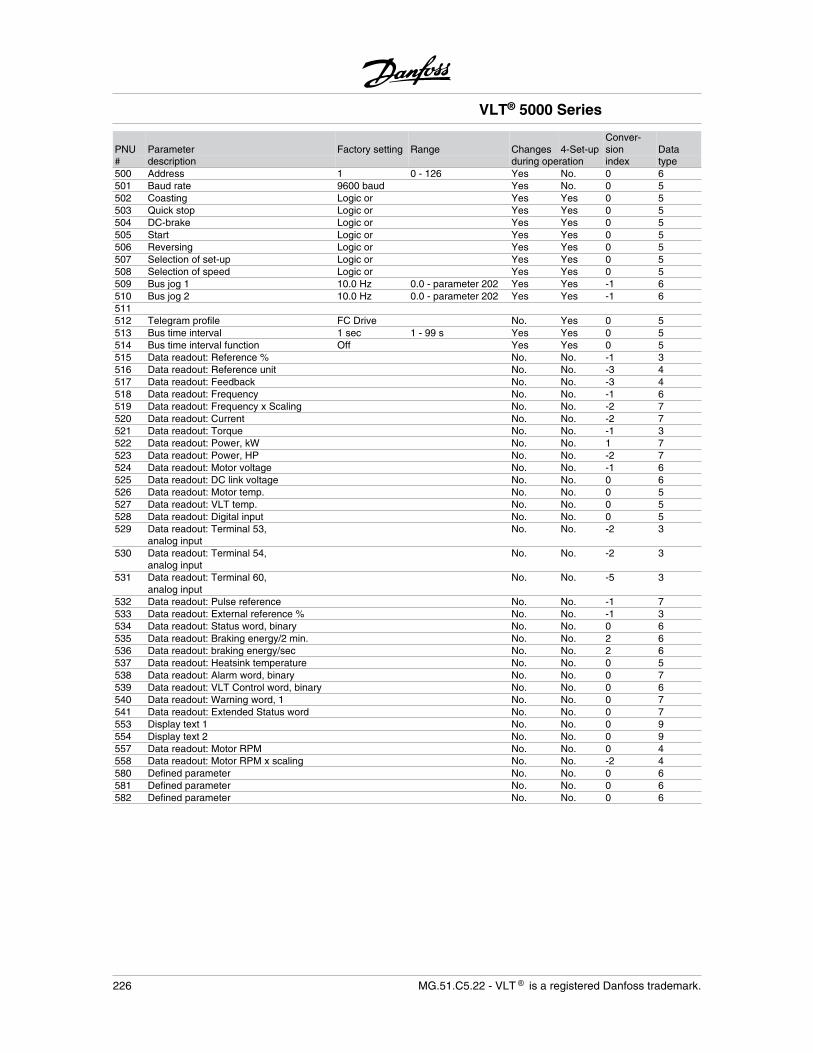
PNU Parameter Factory setting Range Changes 4-Set-upConver-sion Data
# description during operation index type500 Address 1 0 - 126 Yes No. 0 6501 Baud rate 9600 baud Yes No. 0 5502 Coasting Logic or Yes Yes 0 5503 Quick stop Logic or Yes Yes 0 5504 DC-brake Logic or Yes Yes 0 5505 Start Logic or Yes Yes 0 5506 Reversing Logic or Yes Yes 0 5507 Selection of set-up Logic or Yes Yes 0 5508 Selection of speed Logic or Yes Yes 0 5509 Bus jog 1 10.0 Hz 0.0 - parameter 202 Yes Yes -1 6510 Bus jog 2 10.0 Hz 0.0 - parameter 202 Yes Yes -1 6511512 Telegram profile FC Drive No. Yes 0 5513 Bus time interval 1 sec 1 - 99 s Yes Yes 0 5514 Bus time interval function Off Yes Yes 0 5515 Data readout: Reference % No. No. -1 3516 Data readout: Reference unit No. No. -3 4517 Data readout: Feedback No. No. -3 4518 Data readout: Frequency No. No. -1 6519 Data readout: Frequency x Scaling No. No. -2 7520 Data readout: Current No. No. -2 7521 Data readout: Torque No. No. -1 3522 Data readout: Power, kW No. No. 1 7523 Data readout: Power, HP No. No. -2 7524 Data readout: Motor voltage No. No. -1 6525 Data readout: DC link voltage No. No. 0 6526 Data readout: Motor temp. No. No. 0 5527 Data readout: VLT temp. No. No. 0 5528 Data readout: Digital input No. No. 0 5529 Data readout: Terminal 53,
analog inputNo. No. -2 3
530 Data readout: Terminal 54,analog input
No. No. -2 3
531 Data readout: Terminal 60,analog input
No. No. -5 3
532 Data readout: Pulse reference No. No. -1 7533 Data readout: External reference % No. No. -1 3534 Data readout: Status word, binary No. No. 0 6535 Data readout: Braking energy/2 min. No. No. 2 6536 Data readout: braking energy/sec No. No. 2 6537 Data readout: Heatsink temperature No. No. 0 5538 Data readout: Alarm word, binary No. No. 0 7539 Data readout: VLT Control word, binary No. No. 0 6540 Data readout: Warning word, 1 No. No. 0 7541 Data readout: Extended Status word No. No. 0 7553 Display text 1 No. No. 0 9554 Display text 2 No. No. 0 9557 Data readout: Motor RPM No. No. 0 4558 Data readout: Motor RPM x scaling No. No. -2 4580 Defined parameter No. No. 0 6581 Defined parameter No. No. 0 6582 Defined parameter No. No. 0 6
VLT® 5000 Series
226 MG.51.C5.22 - VLT is a registered Danfoss trademark.
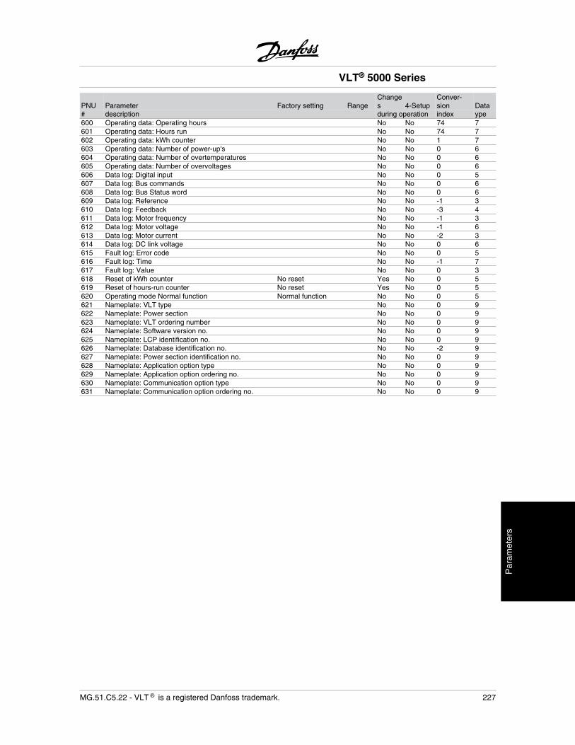
PNU Parameter Factory setting RangeChanges 4-Setup
Conver-sion Data
# description during operation index ype600 Operating data: Operating hours No No 74 7601 Operating data: Hours run No No 74 7602 Operating data: kWh counter No No 1 7603 Operating data: Number of power-up's No No 0 6604 Operating data: Number of overtemperatures No No 0 6605 Operating data: Number of overvoltages No No 0 6606 Data log: Digital input No No 0 5607 Data log: Bus commands No No 0 6608 Data log: Bus Status word No No 0 6609 Data log: Reference No No -1 3610 Data log: Feedback No No -3 4611 Data log: Motor frequency No No -1 3612 Data log: Motor voltage No No -1 6613 Data log: Motor current No No -2 3614 Data log: DC link voltage No No 0 6615 Fault log: Error code No No 0 5616 Fault log: Time No No -1 7617 Fault log: Value No No 0 3618 Reset of kWh counter No reset Yes No 0 5619 Reset of hours-run counter No reset Yes No 0 5620 Operating mode Normal function Normal function No No 0 5621 Nameplate: VLT type No No 0 9622 Nameplate: Power section No No 0 9623 Nameplate: VLT ordering number No No 0 9624 Nameplate: Software version no. No No 0 9625 Nameplate: LCP identification no. No No 0 9626 Nameplate: Database identification no. No No -2 9627 Nameplate: Power section identification no. No No 0 9628 Nameplate: Application option type No No 0 9629 Nameplate: Application option ordering no. No No 0 9630 Nameplate: Communication option type No No 0 9631 Nameplate: Communication option ordering no. No No 0 9
VLT® 5000 Series
MG.51.C5.22 - VLT is a registered Danfoss trademark. 227
Par
amet
ers
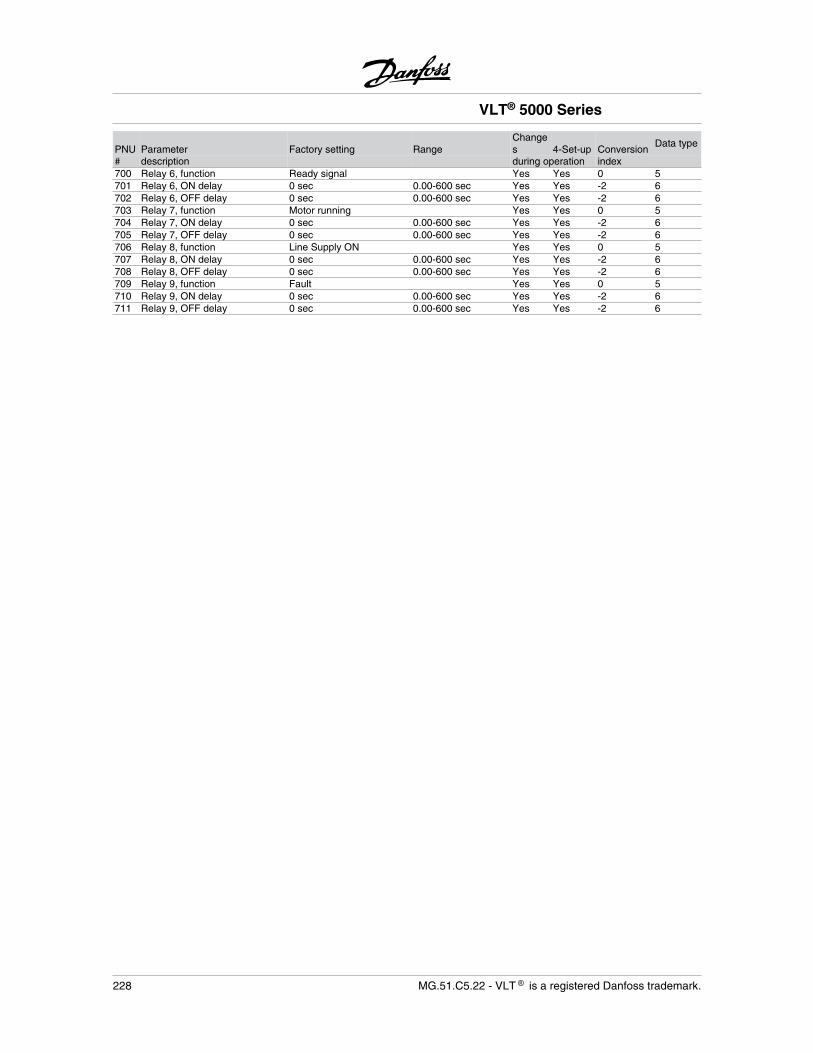
PNU Parameter Factory setting RangeChanges 4-Set-up Conversion
Data type
# description during operation index700 Relay 6, function Ready signal Yes Yes 0 5701 Relay 6, ON delay 0 sec 0.00-600 sec Yes Yes -2 6702 Relay 6, OFF delay 0 sec 0.00-600 sec Yes Yes -2 6703 Relay 7, function Motor running Yes Yes 0 5704 Relay 7, ON delay 0 sec 0.00-600 sec Yes Yes -2 6705 Relay 7, OFF delay 0 sec 0.00-600 sec Yes Yes -2 6706 Relay 8, function Line Supply ON Yes Yes 0 5707 Relay 8, ON delay 0 sec 0.00-600 sec Yes Yes -2 6708 Relay 8, OFF delay 0 sec 0.00-600 sec Yes Yes -2 6709 Relay 9, function Fault Yes Yes 0 5710 Relay 9, ON delay 0 sec 0.00-600 sec Yes Yes -2 6711 Relay 9, OFF delay 0 sec 0.00-600 sec Yes Yes -2 6
VLT® 5000 Series
228 MG.51.C5.22 - VLT is a registered Danfoss trademark.
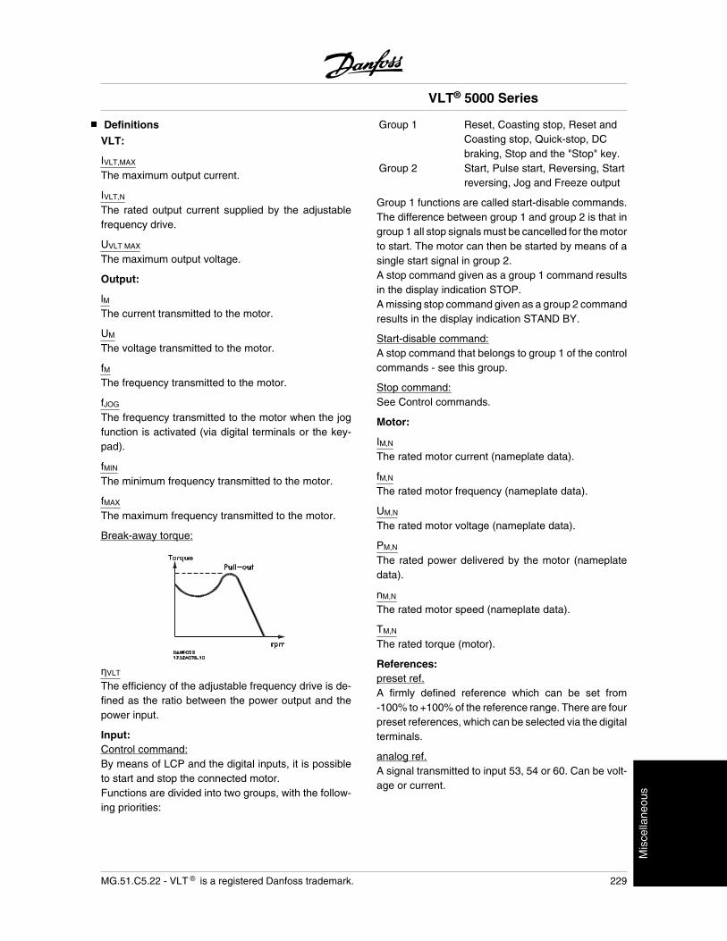
Definitions
VLT:
IVLT,MAX
The maximum output current.
IVLT,N
The rated output current supplied by the adjustablefrequency drive.
UVLT MAX
The maximum output voltage.
Output:
lMThe current transmitted to the motor.
UM
The voltage transmitted to the motor.
fMThe frequency transmitted to the motor.
fJOG
The frequency transmitted to the motor when the jogfunction is activated (via digital terminals or the key-pad).
fMIN
The minimum frequency transmitted to the motor.
fMAX
The maximum frequency transmitted to the motor.
Break-away torque:
VLT
The efficiency of the adjustable frequency drive is de-fined as the ratio between the power output and thepower input.
Input:Control command:By means of LCP and the digital inputs, it is possibleto start and stop the connected motor.Functions are divided into two groups, with the follow-ing priorities:
Group 1 Reset, Coasting stop, Reset andCoasting stop, Quick-stop, DCbraking, Stop and the "Stop" key.
Group 2 Start, Pulse start, Reversing, Startreversing, Jog and Freeze output
Group 1 functions are called start-disable commands.The difference between group 1 and group 2 is that ingroup 1 all stop signals must be cancelled for the motorto start. The motor can then be started by means of asingle start signal in group 2.A stop command given as a group 1 command resultsin the display indication STOP.A missing stop command given as a group 2 commandresults in the display indication STAND BY.
Start-disable command:A stop command that belongs to group 1 of the controlcommands - see this group.
Stop command:See Control commands.
Motor:
IM,N
The rated motor current (nameplate data).
fM,N
The rated motor frequency (nameplate data).
UM,N
The rated motor voltage (nameplate data).
PM,N
The rated power delivered by the motor (nameplatedata).
nM,N
The rated motor speed (nameplate data).
TM,N
The rated torque (motor).
References:preset ref.A firmly defined reference which can be set from-100% to +100% of the reference range. There are fourpreset references, which can be selected via the digitalterminals.
analog ref.A signal transmitted to input 53, 54 or 60. Can be volt-age or current.
VLT® 5000 Series
MG.51.C5.22 - VLT is a registered Danfoss trademark. 229
Mis
cella
neou
s
pulse ref.A signal transmitted to the digital inputs (terminal 17 or29).
binary ref.A signal transmitted to the serial communication port.
RefMIN
The smallest value which the reference signal mayhave. Set in parameter 204.
RefMAX
The maximum value which the reference signal mayhave. Set in parameter 205.
Miscellaneous:
GLCB:Ground Leakage Circuit Breaker.
lsb:Least significant bit.Used in serial communication.
msbMost significant bit.Used in serial communication.
PID:The PID regulator maintains the desired speed (pres-sure, temperature, etc.) by adjusting the output fre-quency to match the varying load.
Trip:A state which occurs in different situations, e.g., if theadjustable frequency drive is subjected to an overtem-perature. A trip can be cancelled by pressing reset or,in some cases, automatically.
Trip-locked:A state which occurs in different situations, e.g., if theadjustable frequency drive is subject to an overtem-perature. A locked trip can be cancelled by cutting offline power and restarting the adjustable frequencydrive.
Initializing:If initializing is carried out, the adjustable frequencydrive returns to the factory setting.
Set-up:There are four set-ups, in which it is possible to saveparameter settings. It is possible to change betweenthe four parameter set-ups and to edit one set-up,while another set-up is active.
LCP:The control panel, which makes up a complete inter-face for control and programming of VLT 5000 Series.The control panel is detachable and may, as an alter-native, be installed up to 9.8 ft (3 meters) away fromthe adjustable frequency drive, i.e., in a front panel, bymeans of the installation kit option.
VVC plus
If compared with standard voltage/frequency ratio con-
trol, VVCplus improves the dynamics and the stability,both when the speed reference is changed and in re-lation to the load torque.
Slip compensation:Normally, the motor speed will be affected by the load,but this load dependence is unwanted. The adjustablefrequency drive compensates for the slip by giving thefrequency a supplement that follows the measured ef-fective current.
Thermistor:A temperature-dependent resistor placed where thetemperature is to be monitored (adjustable frequencydrive or motor).
Analog inputs:The analog inputs can be used for controlling variousfunctions of the adjustable frequency drive.There are two types of analog inputs:Current input, 0-20 mAVoltage input, 0-10 V DC.
Analog outputs:There are two analog outputs, which are able to supplya signal of 0-20 mA, 4-20 mA or a digital signal.
Digital inputs:The digital inputs can be used for controlling variousfunctions of the adjustable frequency drive.
Digital outputs:There are four digital outputs, two of which activate arelay switch. The outputs are able to supply a 24 V DC(max. 40 mA) signal.
Brake resistor:The brake resistor is a module capable of absorbingthe braking energy that is generated in regenerativebraking. This regenerative braking energy increasesthe intermediate circuit voltage, while a brake chopperensures that the energy is transmitted to the brake re-sistor.
VLT® 5000 Series
230 MG.51.C5.22 - VLT is a registered Danfoss trademark.
Pulse encoder:An external, digital pulse transmitter used for feedingback information on motor speed. The encoder is usedin applications where great accuracy in speed controlis required.
AWG:Means American Wire Gauge, i.e., the Americanmeasuring unit for cable cross-section.
Manual initialization:Press the [CHANGE DATA] + [MENU] + [OK] keys atthe same time to carry out manual initialization.
60° AVMSwitching pattern called 60° Asynchronous VectorModulation.
SFAVMSwitching pattern called Stator Flux-oriented Asyn-chronous Vector Modulation.
Automatic motor adjustment, AMA:Automatic motor adjustment algorithm, which deter-mines the electrical parameters for the connected mo-tor, at standstill.
On-line/off-line parameters:On-line parameters are activated immediately after thedata value is changed. Off-line parameters are not ac-tivated until OK has been entered on the control unit.
VT characteristics:Variable torque characteristics, used for pumps andfans.
CT characteristics:Constant torque characteristics, used for all applica-tions, such as conveyor belts and cranes. CT charac-teristics are not used for pumps and fans.
MCM:Stands for Mille Circular Mil, an American measuring
unit for cable cross-section. 1 MCM • 0.5067 mm2.
VLT® 5000 Series
MG.51.C5.22 - VLT is a registered Danfoss trademark. 231
Mis
cella
neou
s
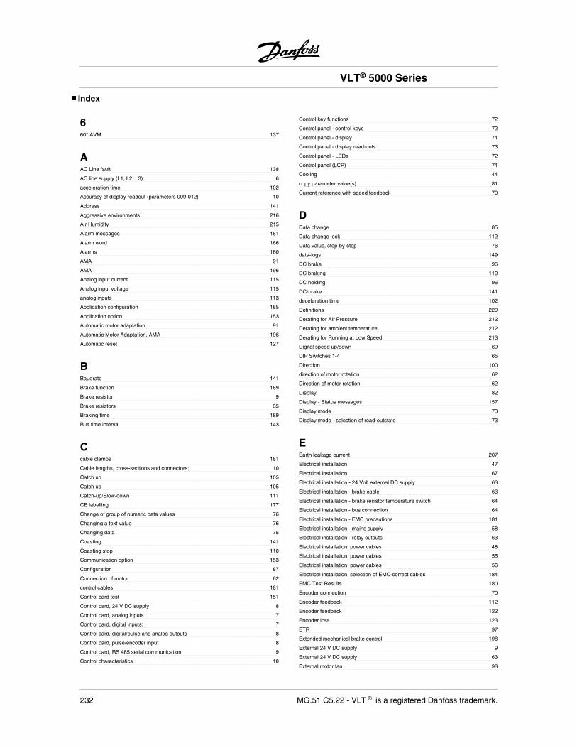
Index
660° AVM 137
AAC Line fault 138
AC line supply (L1, L2, L3): 6
acceleration time 102
Accuracy of display readout (parameters 009-012) 10
Address 141
Aggressive environments 216
Air Humidity 215
Alarm messages 161
Alarm word 166
Alarms 160
AMA 91
AMA 196
Analog input current 115
Analog input voltage 115
analog inputs 113
Application configuration 185
Application option 153
Automatic motor adaptation 91
Automatic Motor Adaptation, AMA 196
Automatic reset 127
BBaudrate 141
Brake function 189
Brake resistor 9
Brake resistors 35
Braking time 189
Bus time interval 143
Ccable clamps 181
Cable lengths, cross-sections and connectors: 10
Catch up 105
Catch up 105
Catch-up/Slow-down 111
CE labelling 177
Change of group of numeric data values 76
Changing a text value 76
Changing data 75
Coasting 141
Coasting stop 110
Communication option 153
Configuration 87
Connection of motor 62
control cables 181
Control card test 151
Control card, 24 V DC supply 8
Control card, analog inputs 7
Control card, digital inputs: 7
Control card, digital/pulse and analog outputs 8
Control card, pulse/encoder input 8
Control card, RS 485 serial communication 9
Control characteristics 10
Control key functions 72
Control panel - control keys 72
Control panel - display 71
Control panel - display read-outs 73
Control panel - LEDs 72
Control panel (LCP) 71
Cooling 44
copy parameter value(s) 81
Current reference with speed feedback 70
DData change 85
Data change lock 112
Data value, step-by-step 76
data-logs 149
DC brake 96
DC braking 110
DC holding 96
DC-brake 141
deceleration time 102
Definitions 229
Derating for Air Pressure 212
Derating for ambient temperature 212
Derating for Running at Low Speed 213
Digital speed up/down 69
DIP Switches 1-4 65
Direction 100
direction of motor rotation 62
Direction of motor rotation 62
Display 82
Display - Status messages 157
Display mode 73
Display mode - selection of read-outstate 73
EEarth leakage current 207
Electrical installation 47
Electrical installation 67
Electrical installation - 24 Volt external DC supply 63
Electrical installation - brake cable 63
Electrical installation - brake resistor temperature switch 64
Electrical installation - bus connection 64
Electrical installation - EMC precautions 181
Electrical installation - mains supply 58
Electrical installation - relay outputs 63
Electrical installation, power cables 48
Electrical installation, power cables 55
Electrical installation, power cables 56
Electrical installation, selection of EMC-correct cables 184
EMC Test Results 180
Encoder connection 70
Encoder feedback 112
Encoder feedback 122
Encoder loss 123
ETR 97
Extended mechanical brake control 198
External 24 V DC supply 9
External 24 V DC supply 63
External motor fan 98
VLT® 5000 Series
232 MG.51.C5.22 - VLT is a registered Danfoss trademark.
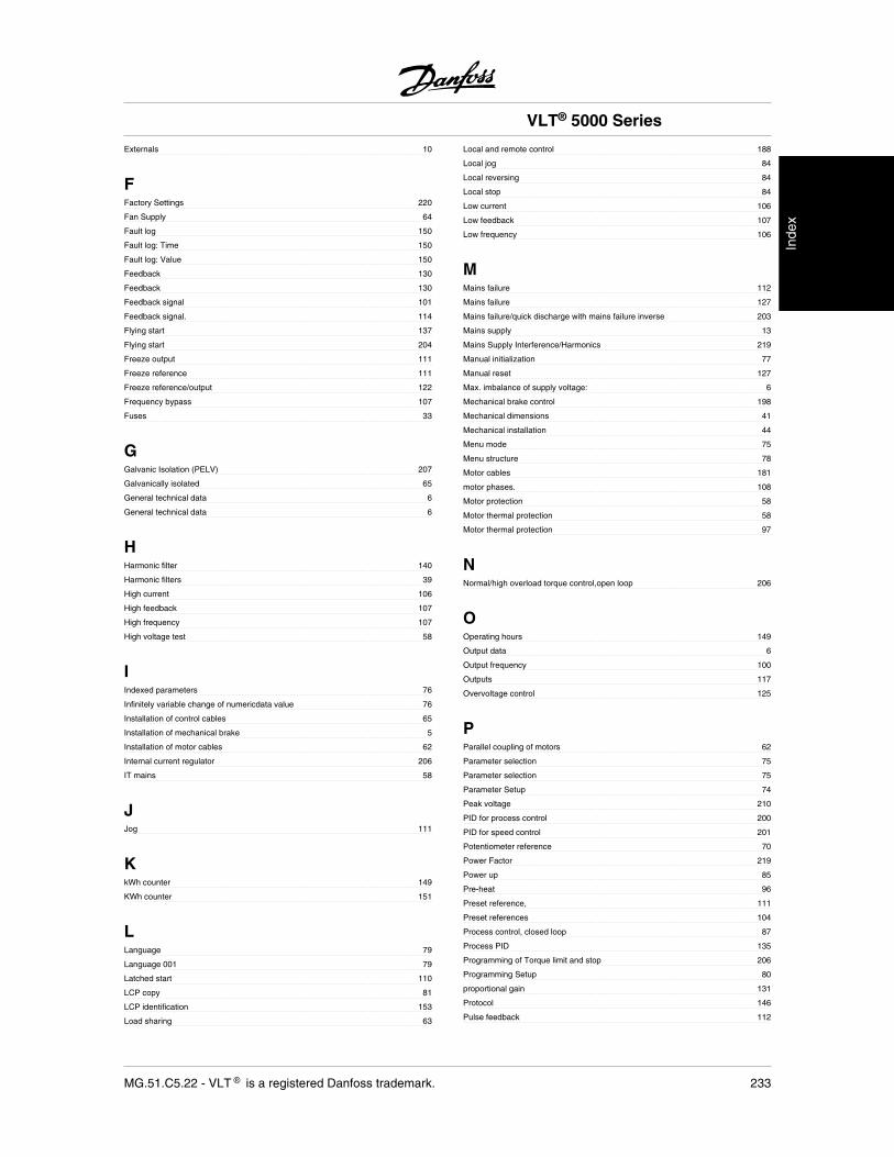
Externals 10
FFactory Settings 220
Fan Supply 64
Fault log 150
Fault log: Time 150
Fault log: Value 150
Feedback 130
Feedback 130
Feedback signal 101
Feedback signal. 114
Flying start 137
Flying start 204
Freeze output 111
Freeze reference 111
Freeze reference/output 122
Frequency bypass 107
Fuses 33
GGalvanic Isolation (PELV) 207
Galvanically isolated 65
General technical data 6
General technical data 6
HHarmonic filter 140
Harmonic filters 39
High current 106
High feedback 107
High frequency 107
High voltage test 58
IIndexed parameters 76
Infinitely variable change of numericdata value 76
Installation of control cables 65
Installation of mechanical brake 5
Installation of motor cables 62
Internal current regulator 206
IT mains 58
JJog 111
KkWh counter 149
KWh counter 151
LLanguage 79
Language 001 79
Latched start 110
LCP copy 81
LCP identification 153
Load sharing 63
Local and remote control 188
Local jog 84
Local reversing 84
Local stop 84
Low current 106
Low feedback 107
Low frequency 106
MMains failure 112
Mains failure 127
Mains failure/quick discharge with mains failure inverse 203
Mains supply 13
Mains Supply Interference/Harmonics 219
Manual initialization 77
Manual reset 127
Max. imbalance of supply voltage: 6
Mechanical brake control 198
Mechanical dimensions 41
Mechanical installation 44
Menu mode 75
Menu structure 78
Motor cables 181
motor phases. 108
Motor protection 58
Motor thermal protection 58
Motor thermal protection 97
NNormal/high overload torque control,open loop 206
OOperating hours 149
Output data 6
Output frequency 100
Outputs 117
Overvoltage control 125
PParallel coupling of motors 62
Parameter selection 75
Parameter selection 75
Parameter Setup 74
Peak voltage 210
PID for process control 200
PID for speed control 201
Potentiometer reference 70
Power Factor 219
Power up 85
Pre-heat 96
Preset reference, 111
Preset references 104
Process control, closed loop 87
Process PID 135
Programming of Torque limit and stop 206
Programming Setup 80
proportional gain 131
Protocol 146
Pulse feedback 112
VLT® 5000 Series
MG.51.C5.22 - VLT is a registered Danfoss trademark. 233
Inde
x
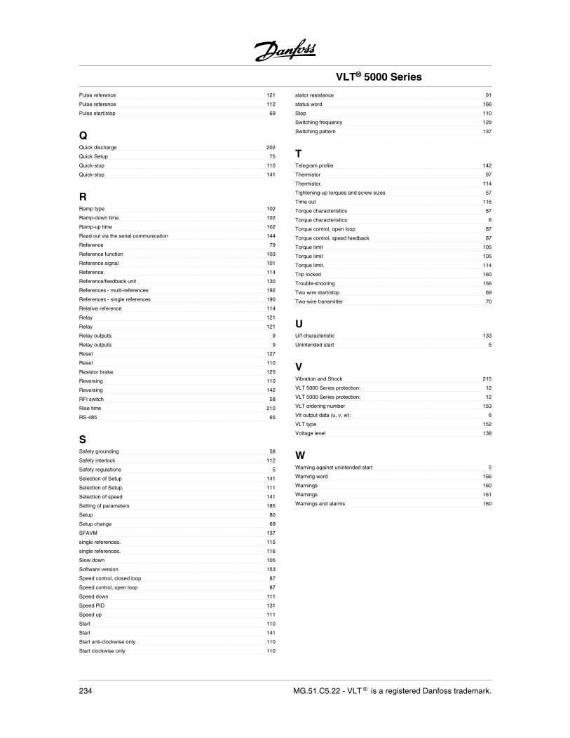
Pulse reference 121
Pulse reference 112
Pulse start/stop 69
QQuick discharge 202
Quick Setup 75
Quick-stop 110
Quick-stop 141
RRamp type 102
Ramp-down time 102
Ramp-up time 102
Read out via the serial communication 144
Reference 79
Reference function 103
Reference signal 101
Reference. 114
Reference/feedback unit 130
References - multi-references 192
References - single references 190
Relative reference 114
Relay 121
Relay 121
Relay outputs: 9
Relay outputs: 9
Reset 127
Reset 110
Resistor brake 125
Reversing 110
Reversing 142
RFI switch 58
Rise time 210
RS-485 65
SSafety grounding 58
Safety interlock 112
Safety regulations 5
Selection of Setup 141
Selection of Setup, 111
Selection of speed 141
Setting of parameters 185
Setup 80
Setup change 69
SFAVM 137
single references. 115
single references. 116
Slow down 105
Software version 153
Speed control, closed loop 87
Speed control, open loop 87
Speed down 111
Speed PID 131
Speed up 111
Start 110
Start 141
Start anti-clockwise only 110
Start clockwise only 110
stator resistance 91
status word 166
Stop 110
Switching frequency 129
Switching pattern 137
TTelegram profile 142
Thermistor 97
Thermistor. 114
Tightening-up torques and screw sizes 57
Time out 116
Torque characteristics 87
Torque characteristics: 6
Torque control, open loop 87
Torque control, speed feedback 87
Torque limit 105
Torque limit 105
Torque limit. 114
Trip locked 160
Trouble-shooting 156
Two wire start/stop 69
Two-wire transmitter 70
UU/f characteristic 133
Unintended start 5
VVibration and Shock 215
VLT 5000 Series protection: 12
VLT 5000 Series protection: 12
VLT ordering number 153
Vlt output data (u, v, w): 6
VLT type 152
Voltage level 138
WWarning against unintended start 5
Warning word 166
Warnings 160
Warnings 161
Warnings and alarms 160
VLT® 5000 Series
234 MG.51.C5.22 - VLT is a registered Danfoss trademark.
Rev. 2006-12-12
www.danfoss.com/drives
175R5271 MG51C522
*MG51C522*
MG
51C522
VLT
5000 Instru
ction
Man
ual