Embed Size (px)
Citation preview

Instruction Manual (ver. FS)
FS-1FS-2FS-3FS-4FS-5

2i Por t ver. FS Ins t ruct ion Manual
IntroductionThe iPort™ FS is a free-standing docking system that allowsan Apple iPod® to become part of a whole-home audio system, and/or to be used as a source in a variety of localaudio systems. The iPort Dock can be placed on a desk,table or other convenient location, allowing quick and easyinsertion of an iPod, and connects the iPod to both theaudio/video system and the user’s computer. By pressing asingle button on the iPort the user can change the iPodfrom the streaming (listening) mode to the music transfermode, allowing the transfer of content from the computerto the iPod.
Before installing and using the iPort please read and followall of the instructions in this guide carefully.
iPort System Components and CapabilitiesThis manual covers five iPort free-standing systems (FS-1 – FS-5). Each system has different capabilitiesand includes different components. Except where noted, connections and installation are the samefor all five systems.
FS-1 System Capabilities:• Delivers local-zone unbalanced audio and video from the iPod (up to 25 feet)
• Connects to a computer, allowing transfer of content to the iPod while it is docked
• Charges the iPod while it is docked
FS-1 System Box Contents:(1) iPort Dock
(1) iPort Basic Connection Box
(1) 6.5 foot (2-Meter) Double Cable
(1) 15V DC Regulated Power Supply
3i Por t ver. FS Ins t ruct ion Manual
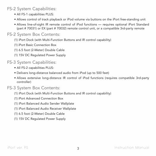
FS-2 System Capabilities:• All FS-1 capabilities PLUS:
• Allows control of track playback or iPod volume via buttons on the iPort free-standing unit
• Allows line-of-sight IR remote control of iPod functions — requires optional iPort Standard(part # 70031) or EX (part # 70032) remote control unit, or a compatible 3rd-party remote
FS-2 System Box Contents:(1) iPort Dock (with Multi-Function Buttons and IR control capability)
(1) iPort Basic Connection Box
(1) 6.5 foot (2-Meter) Double Cable
(1) 15V DC Regulated Power Supply
FS-3 System Capabilities:• All FS-2 capabilities PLUS:
• Delivers long-distance balanced audio from iPod (up to 500 feet)
• Allows extensive long-distance IR control of iPod functions (requires compatible 3rd-party controller)
FS-3 System Box Contents:(1) iPort Dock (with Multi-Function Buttons and IR control capability)
(1) iPort Advanced Connection Box
(1) iPort Balanced Audio Sender Wallplate
(1) iPort Balanced Audio Receiver Wallplate
(1) 6.5 foot (2-Meter) Double Cable
(1) 15V DC Regulated Power Supply

4i Por t ver. FS Ins t ruct ion Manual
FS-4 System Capabilities:• All FS-3 capabilities PLUS:
• Allows extensive long-distance RS-232 control of iPod functions with 2-way communication(requires compatible 3rd-party controller)
FS-4 System Box Contents:(1) iPort Dock (with Multi-Function Buttons and IR control capability)
(1) Advanced Connection Box (with RS-232 capability)
(1) iPort Balanced Audio Sender Wallplate
(1) iPort Balanced Audio Receiver Wallplate
(1) 6.5 foot (2-Meter) Double Cable
(1) RS-232 Cable (RJ-11-to-DB-9 connections)
(1) 15V DC Regulated Power Supply
FS-5 System Capabilities:• All FS-4 capabilities PLUS:
• Delivers long-distance balanced video from iPod photo players
FS-5 System Box Contents:(1) iPort Dock (with Multi-Function Buttons and IR control capability)
(1) Advanced Connection Box (with RS-232 capability)
(1) iPort Balanced Audio Sender Wallplate
(1) iPort Balanced Audio Receiver Wallplate
(1) iPort Balanced Video Sender Wallplate
(1) iPort Balanced Video Receiver Wallplate
(1) 6.5 foot (2-Meter) Double Cable
(1) RS-232 Cable (RJ-11-to-DB-9 connections)
(1) 15V DC Regulated Power Supply
5i Por t ver. FS Ins t ruct ion Manual
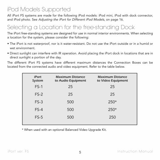
iPod Models SupportedAll iPort FS systems are made for the following iPod models: iPod mini, iPod with dock connector,and iPod photo. See Adjusting the iPort for Different iPod Models, on page 16.
Selecting a Location for the free-standing DockThe iPort free-standing systems are designed for use in normal interior environments. When selectinga location for the system, please consider the following:
• The iPort is not waterproof, nor is it water-resistant. Do not use the iPort outside or in a humid orwet environment.
• Direct sunlight can interfere with IR operation. Avoid placing the iPort dock in locations that are indirect sunlight a portion of the day.
The different iPort FS systems have different maximum distances the Connection Boxes can be located from the connected audio and video equipment. Refer to the table below.
* When used with an optional Balanced Video Upgrade Kit.
iPort Maximum Distance Maximum DistanceSystem to Audio Equipment to Video Equipment
FS-1 25 25
FS-2 25 25
FS-3 500 250*
FS-4 500 250*
FS-5 500 250

i Por t ver. FS Ins t ruct ion Manual
iPort Connections and ControlsiPort Dock (see Figure 2):Function Selector/Status Indicator: Whenever an iPod isdocked into the iPort the Function Selector/StatusIndicator glows white and the iPort enters the MusicStream (listening) mode. To switch the iPort to the DataTransfer mode, press the Function Selector until the StatusIndicator turns red. Data can then be transferred from thecomputer to the docked iPod. To switch back to the Music Stream mode, eject the iPod from your computer byissuing an eject command via your computer’s music transfersoftware. (The iPort will not switch back to the listening modewhile data is being transferred from the computer to the iPod.)
Note: The iPort does not output audio or video whilein the Data Transfer mode.
Multi-Function Buttons (FS-2 – FS-5 only): When theVolume Control Switch (see below) is set to the Variableposition, pressing the left button lowers the volume; pressing the right button raises the volume. When theVolume Control Switch is in the Fixed position, pressingthe left button changes the iPod stream to the previoustrack; pressing the right button changes the iPod streamto the next track.
Multi-Pin Connector: Connects the iPort dock to theConnection Box and to a computer, using the suppliedDouble Cable.
Fixed/Variable Volume Switch (FS-2 – FS-5 only): When the switch is towards the front of the iPort(Variable position) the Multi-Function buttons act as Volume Control buttons. When the switch istowards the rear of the iPort (Fixed position) the Multi-Function Buttons act as Track Skip buttons.Note: On the FS-1 this switch acts as a brightness switch for the Status Indicator: The front position is dim; the rear position is bright.
6
Figure 2: iPort Dock Connections and Controls
Function Selector / Status Indicator
Left Multi-FunctionButton
Right Multi-FunctionButton
Var.
Fixed
Multi-Pin ConnectorFixed/VariableVolume Switch
Underside of iPort Dock

7i Por t ver. FS Ins t ruct ion Manual
Basic Connection Box (FS-1 – FS-2 only) See Figure 3:Line Out Jack: Connects to powered speakers (such ascomputer audio systems). Do not connect headphones.
Multi-Pin Connector: Connects to the iPort Dock,using the supplied Double Cable.
Power Supply Jack: Connects to the supplied +15VDC power supply.
S-Video and Composite Video Jacks: Connect to avideo monitor.
Note: You can use both the S-Video and compositevideo connections simultaneously.
Left & Right Audio Jacks: Connect to the local audiosystem.
Advanced Connection Box (FS-3 – FS-5 only) See Figure 4:Power Supply Jack: Connects to the supplied +15VDC power supply.
IR Jack: 3.5mm mini jack connects to a compatible IRcontrol system.*
Audio Connector: RJ-45 jack connects to the iPortAudio Sender Wallplate via Cat5 cable.
Multi-Pin Connector: Connects to the iPort Dockusing the supplied Double Cable.
Video Connector: RJ-45 jack connects to the iPortVideo Sender Wallplate via Cat5 cable.
RS-232 Connector: RJ-11 jack connects to a compatibleRS-232 control system.*
*Do not use if connecting control systems to the Balanced Audio Receiver Wallplate (see pages 12 – 13).
Figure 3: iPort FS-1 and FS-2 Basic Connection BoxConnections
Figure 4: iPort FS-3 – FS-5 Advanced Connection BoxConnections
Line Out
To iPort
Power
Video Audio
Line OutJack
Power SupplyJack
Multi-PinConnector
S-VideoJack
Left & Right Audio Jacks
Composite VideoJack
REAR
FRONT
To iPort
Power IR To Audio WP To Video WP RS-232
IR Jack
Power Supply Jack
Multi-PinConnector
AudioConnector
VideoConnector
RS-232Connector

8i Por t ver. FS Ins t ruct ion Manual
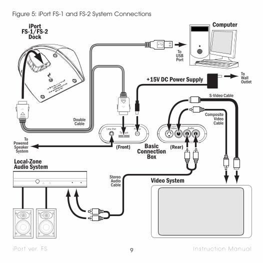
iPort System Connections — FS-1 / FS-2See Figure 5The iPort FS-1 and FS-2 systems’ unbalanced audio and video outputs are designed for use in a local-zone system where the audio/video equipment is located less than 25 feet from the iPort BasicConnection Box.
In FS-1 systems the iPod is controlled only from its front panel; in FS-2 systems the iPod can be controlled from its front panel, from the Multi-Function Buttons on the iPort Dock (see above), or froman optional iPort Standard or EX remote control (or a compatible 3rd-party remote).
1. The iPort Dock must be located within 2 meters of the Basic Connection Box and within 2 meters ofthe computer. The Connection Box should be located near a source of AC power.
2. Connect the iPort system to the audio and video components as shown in Figure 5:
• Connect the supplied Double Cable to the iPort Dock, the Basic Connection Box and the com-puter’s USB port.
• Use a stereo RCA audio cable to connect the Connection Box to a source input on the local-zoneaudio system.
• Use a composite video and/or S-Video cable to connect the Connection Box to an input on thevideo equipment.
Note: You can use both the S-Video and composite video connections simultaneously.
• If you’re using a powered speaker system (computer speakers) as a local zone audio system, connect the Line Out jack into the powered speaker system’s input.
Note: Do not plug stereo headphones into the Line Out jack.
• Plug the included 15V DC power supply into the Power connector on the Connection Box.
3. After confirming that all of the connections have been made correctly, plug the power supply intoa wall outlet.
9i Por t ver. FS Ins t ruct ion Manual
Computer
Local-ZoneAudio System
Video System
BasicConnection
Box
+15V DC Power Supply
iPortFS-1/FS-2
Dock
(Front) (Rear)
VideoLine Out
To iPort
Power Audio
ToWallOutlet
ToPoweredSpeakerSystem
ToUSBPort
S-Video Cable
CompositeVideoCable
StereoAudioCable
DoubleCable
Figure 5: iPort FS-1 and FS-2 System Connections
10i Por t ver. FS Ins t ruct ion Manual
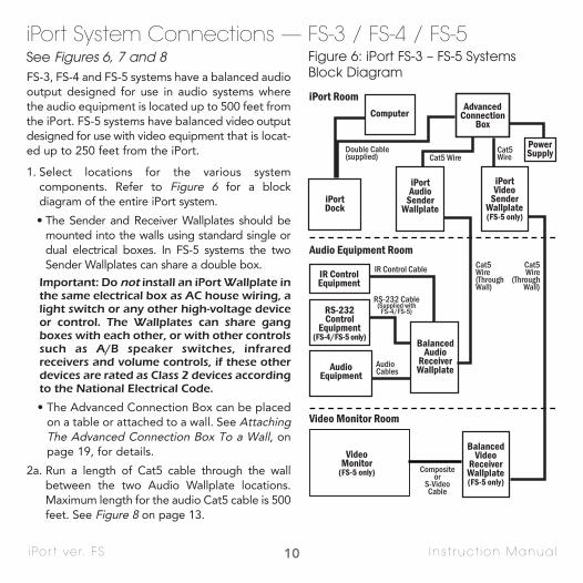
iPort System Connections — FS-3 / FS-4 / FS-5See Figures 6, 7 and 8FS-3, FS-4 and FS-5 systems have a balanced audiooutput designed for use in audio systems wherethe audio equipment is located up to 500 feet fromthe iPort. FS-5 systems have balanced video outputdesigned for use with video equipment that is locat-ed up to 250 feet from the iPort.
1. Select locations for the various system components. Refer to Figure 6 for a block diagram of the entire iPort system.
• The Sender and Receiver Wallplates should bemounted into the walls using standard single ordual electrical boxes. In FS-5 systems the twoSender Wallplates can share a double box.
Important: Do not install an iPort Wallplate inthe same electrical box as AC house wiring, alight switch or any other high-voltage deviceor control. The Wallplates can share gangboxes with each other, or with other controlssuch as A/B speaker switches, infraredreceivers and volume controls, if these otherdevices are rated as Class 2 devices accordingto the National Electrical Code.
• The Advanced Connection Box can be placedon a table or attached to a wall. See AttachingThe Advanced Connection Box To a Wall, onpage 19, for details.
2a. Run a length of Cat5 cable through the wallbetween the two Audio Wallplate locations.Maximum length for the audio Cat5 cable is 500feet. See Figure 8 on page 13.
iPort Room
Audio Equipment Room
Video Monitor Room
iPortDock
ComputerAdvanced
ConnectionBox
iPortVideo
SenderWallplate(FS-5 only)
BalancedVideo
ReceiverWallplate(FS-5 only)
iPortAudio
SenderWallplate
BalancedAudio
ReceiverWallplate
PowerSupply
RS-232Control
Equipment(FS-4/FS-5 only)
IR ControlEquipment
AudioEquipment
VideoMonitor
(FS-5 only)
Double Cable(supplied) Cat5 Wire
Cat5Wire
Cat5Wire(ThroughWall)
Cat5Wire
(ThroughWall)
RS-232 Cable(Supplied with
FS-4/FS-5)
AudioCables
IR Control Cable
Compositeor
S-VideoCable
Figure 6: iPort FS-3 – FS-5 SystemsBlock Diagram
i Por t ver. FS
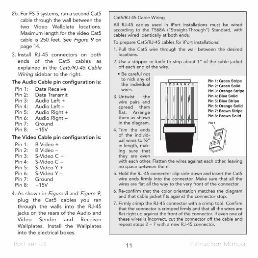
2b. For FS-5 systems, run a second Cat5cable through the wall between thetwo Video Wallplate locations.Maximum length for the video Cat5cable is 250 feet. See Figure 9 onpage 14.
3. Install RJ-45 connectors on bothends of the Cat5 cables asexplained in the Cat5/RJ-45 CableWiring sidebar to the right.
The Audio Cable pin configuration is:Pin 1: Data ReceivePin 2: Data TransmitPin 3: Audio Left +Pin 4: Audio Left –Pin 5: Audio Right +Pin 6: Audio Right –Pin 7: GroundPin 8: +15V
The Video Cable pin configuration is: Pin 1: B Video +Pin 2: B Video –Pin 3: S-Video C +Pin 4: S-Video C –Pin 5: S-Video Y +Pin 6: S-Video Y –Pin 7: GroundPin 8: +15V
4. As shown in Figure 8 and Figure 9,plug the Cat5 cables you ranthrough the walls into the RJ-45jacks on the rears of the Audio andVideo Sender and ReceiverWallplates. Install the Wallplatesinto the electrical boxes.
11 Ins t ruct ion Manual
Cat5/RJ-45 Cable Wiring
All RJ-45 cables used in iPort installations must be wiredaccording to the T568A (“Straight-Through”) Standard, withcables wired identically at both ends.
To prepare Cat5/RJ-45 cables for iPort installations:
1. Pull the Cat5 wire through the wall between the desiredlocations.
2. Use a stripper or knife to strip about 1” of the cable jacketoff each end of the wire.
• Be careful notto nick any ofthe individualwires.
3. Untwist thewire pairs andspread themflat. Arrangethem as shownin the diagram.
4. Trim the endsof the individ-ual wires to ½”in length, mak-ing sure thatthey are evenwith each other. Flatten the wires against each other, leavingno space between them.
5. Hold the RJ-45 connector clip side-down and insert the Cat5wire ends firmly into the connector. Make sure that all thewires are flat all the way to the very front of the connector.
6. Re-confirm that the color orientation matches the diagramand that cable jacket fits against the connector stop.
7. Firmly crimp the RJ-45 connector with a crimp tool. Confirmthat the connector is crimped firmly and that all the wires areflat right up against the front of the connector. If even one ofthese wires is incorrect, cut the connector off the cable andrepeat steps 2 – 7 with a new RJ-45 connector.

i Por t ver. FS
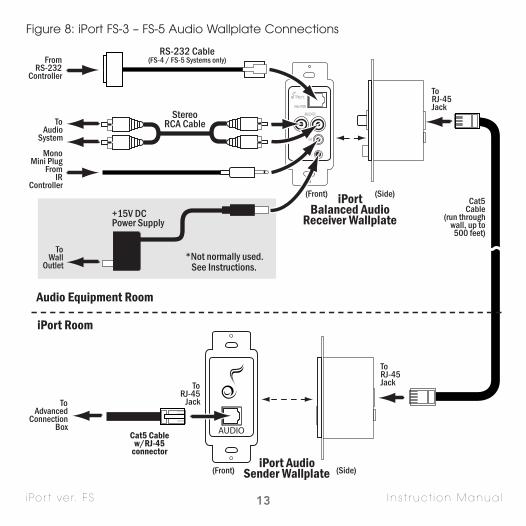
5. Connect the Balanced Audio Receiver Wallplate to the audio system using a stereo audio cable,as shown in Figure 8.
6. If the audio system has a compatible IR control output, use a mono 3.5mm mini cable to connectit to the Balanced Audio Receiver Wallplate’s IR connector, as shown in Figure 8.
7. For FS-4 and FS-5 systems, if the audio system has a compatible RS-232 control output, connect it tothe Balanced Audio Receiver Wallplate’s RS-232 connector using the supplied RS-232 cable, as shownin Figure 8. The Wallplate accepts a male RJ-11 connector with the following pin configuration:
* Only one PC RX and GND pin connection is required.
Note: For complete information about RS-232 connections, programming and operationgo to www.iportmusic.com.
8. Normally, the iPort system’s +15V DC power supply will plug into a wall outlet in the iPort Roomand connect to the Advanced Connection Box (see Step 13 and Figure 10). If this is not possible,you can use a wall outlet in the Audio Equipment Room, as shown in Figure 8. Do NOT plug thepower supply into a wall outlet at this time.
If you are connecting the power supply to the Balanced Audio Receiver Wallplate and it is locatedmore than 250 feet from the Balanced Audio Sender Wallplate: You will need to run a length of16/2 speaker wire through the wall, from the Audio Receiver Wallplate’s Aux Power 2-pin connectorto the Audio Sender Wallplate’s Aux Power 2-pin connector, as shown below in Figure 7. This willavoid performance degradation caused by a loss of DC voltage over wire runs longer than 250 feet
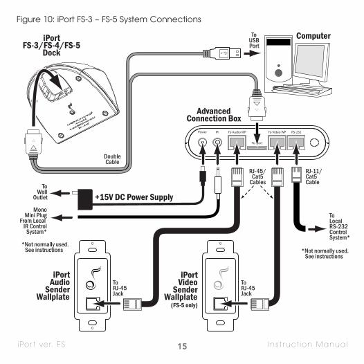
9. As shown in Figure10 on page 15, connect the sup-plied Double Cableto the iPort Dock,the AdvancedConnection Boxand the computer’sUSB port.
10. As shown inFigure 10 on page15, run a length ofCat5 cable from
12 Ins t ruct ion Manual
Pin 1: PC RX*Pin 2: GND*
Pin 3: GND*Pin 4: PC TX
Pin 5: PC RX*Pin 6: Unused
iPort Balanced AudioReceiver Wallplate
iPort Audio SenderWallplate
16/2 Speaker Wire
Figure 7: iPort FS-3 – FS-5 Auxiliary Power Connection
13i Por t ver. FS Ins t ruct ion Manual
Figure 8: iPort FS-3 – FS-5 Audio Wallplate Connections

14i Por t ver. FS Ins t ruct ion Manual
the Advanced Connection Box location to the Audio Sender Wallplate. (For FS-5 systems run asecond length of Cat5 from the Advanced Connection Box to the Video Sender Wallplate.) InstallRJ-45 connectors on both ends of the Cat5 cables as explained in the Cat5/RJ-45 Cable Wiringsidebar on page 11.
11. As shown in Figure 10, plug the audio Cat5 cable into the To Audio Wallplate jack on the AdvancedConnection Box and the RJ-45 jack on the Audio Sender Wallplate.
11a. For FS-5 systems, plug the video Cat5 cable into the To Video Wallplate jack on the AdvancedConnection Box and the RJ-45 jack on the Video Sender Wallplate, as shown in Figure 10.
12. If the IR and/or RS-232 control system is local to the iPort On-Desk System, connect them direct-ly to the their respective jacks on the Advanced Connection Box, as shown in Figure 10. Note: Do not connect the control systems to the Advanced Connection Box if you’ve already connected them to the Balanced Audio Receiver Wallplate, as shown in Figure 8.
13. For FS-5 systems, connect the Video Receiver Wallplate to the video monitor, as shown in Figure 9. Note: You can use both the composite and S-Video connections simultaneously.
14. After confirming that all of the connections have been made correctly, plug the included +15V DCpower supply into the Power connector on the Advanced Connection Box and into a wall outlet.
iPort VideoSender Wallplate
iPort Balanced VideoReceiver Wallplate
ToAdvancedConnectionBox
Cat5 Cablew/RJ-45 Connector
Cat5 Cablerun through wall,
up to 250 feet
iPortRoom
VideoEquipmentRoom
ToVideo
Monitor
Figure 9: iPort FS-5 Video Wallplate Connections
15i Por t ver. FS Ins t ruct ion Manual
Computer
AdvancedConnection Box
iPortAudio
SenderWallplate
+15V DC Power Supply
iPortFS-3/FS-4/FS-5
Dock
To iPort
Power IR To Audio WP To Video WP RS-232
iPortVideo
SenderWallplate
(FS-5 only)
ToWall
Outlet
MonoMini Plug
From Local IR Control
System*
ToLocalRS-232ControlSystem*
ToRJ-45Jack
ToRJ-45Jack
ToUSBPort
DoubleCable
RJ-11/Cat5Cable
RJ-45/Cat5
Cables
*Not normally used. See instructions
*Not normally used. See instructions
Figure 10: iPort FS-3 – FS-5 System Connections
16i Por t ver. FS Ins t ruct ion Manual
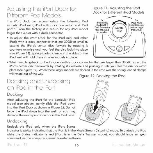
Adjusting the iPort Dock forDifferent iPod ModelsThe iPort Dock can accommodate the following iPod models: iPod mini, iPod with dock connector, and iPodphoto. From the factory it is set-up for any iPod modellarger than 30GB with a dock connector.
• To adjust the iPort Dock for the iPod mini and otheriPods with a dock connector that are 30GB or smaller,extend the iPort’s center disc forward by rotating itcounter-clockwise until you feel the disc lock-into place(see Figure 11). Spring-loaded clamps at the sides of theiPod well will hold these smaller models in place.
• When switching-back to iPod models with a dock connector that are larger than 30GB, retract theiPort’s center disc backwards by rotating it clockwise and pushing it until you feel the disc lock-intoplace (see Figure 11). When these larger models are docked in the iPod well the spring-loaded clampswill rotate out of the way.
Docking and Undockingan iPod in the iPortDockingAfter adjusting the iPort for the particular iPodmodel (see above), gently slide the iPod downinto the iPort Dock as shown in Figure 12. Do notforce the iPod down into the well, or you maydamage the multi-pin connector in the iPort base.
UndockingUndock the iPod only when the iPort StatusIndicator is white, indicating that the iPort is in the Music Stream (listening) mode. To undock the iPodwhile the Status Indicator is red (iPort is in the Data Transfer mode), you should issue an ejectcommand via the computer’s music transfer software.
For iPod mini &iPods with a
Dock Connectorthat are 30GB
or smaller
For iPods with a
Dock Connectorthat are larger
than 30GB RotateDisc
Figure 11: Adjusting the iPortDock for Different iPod Models
Figure 12: Docking the iPod

17i Por t ver. FS Ins t ruct ion Manual
If you undock the iPod while the Status Indicator is red, Macintosh computers and PC computers running Windows (other than Windows XP) will display an error message. (Windows XP permits ‘hot’connection/disconnection via USB.) When you re-dock the iPod there will be a slight delay before youcan use it while the iPort software re-synchronizes with the iPod. See Function Selector/Status Indicator,on page 6, for more information.
Adjusting the iPort Status Indicator Brightness (FS-2 – FS-5 systems)Both the white (Music Stream) and red (Data Transfer) indicators can be set to one of 3 illuminationlevels: BRIGHT, MEDIUM, and DIM. The white (Music Stream) indicator can also be set to OFF. These settings can be changed via RS-232 commands or by either model iPort remote.
Controlling the iPod in an iPort System
IR Control Notes:• iPort IR codes for universal remotes can be downloaded from www.iportmusic.com.
At press time supported formats are: RTI, Phillips Pronto style and Universal Electronics (UEI). Check www.iportmusic.com for the most up-to-date information.
FS-1 systems: • From the iPod front panel.
FS-2 systems: • From the iPod front panel.
• By an optional iPort Standard or EX remote.
FS-3 systems: • From the iPod front panel.
• By an optional iPort Standard or EX remote.
• By IR commands from a compatible controlsystem connected to the Balanced AudioWallplate or the Advanced Connection Box.
FS-4 and FS-5 systems: • From the iPod front panel (when not in RS-232
mode — see RS-232 Control Notes, page 18).
• By an optional iPort Standard or EX remote.
• By IR commands from a compatible controlsystem connected to the Balanced AudioWallplate or the Advanced Connection Box.
• By RS-232 commands from a compatible control system connected to the BalancedAudio Wallplate or the Advanced ConnectionBox. Two-way communication from the iPodincluding iPod metadata — non-program information such as song titles — is available.

18i Por t ver. FS Ins t ruct ion Manual
• Third-generation iPod models only respond to the following IR commands: Play/Pause, Next Track,and Previous Track.
For iPort IR remote control commands, please see the instruction manual accompanying the remote.
RS-232 Control Notes:• When the iPod is in the RS-232 control mode its screen will appear as in Figure 13. When the
iPod is in the normal operation mode its screen will appear as in Figure 14.
• When the RS-232 control mode is active, the iPod’sfront-panel controls will not operate (the iPod inter-face is disabled).
• When the RS-232 control mode is active, the iPodwill only respond to the following IR control codes:Play/Pause, Next Track, Previous Track, Stop. TheiPort will respond to the LED Brightness Adjust IRcontrol codes.
• In FS-5 systems, iPod photo features cannot be controlled in the RS-232 control mode — the iPodmust be taken out of the RS-232 control mode. Thephoto features can then be controlled from theiPod’s front panel controls. The iPod must be putback into the RS-232 control mode to control otherfunctions.
• When the RS-232 control mode is active, if the iPodis placed in the iPort Dock while in the Play mode itwill automatically enter the Pause mode. (This is dueto the iPod protocol.) The installer or programmermay wish to set the RS-232 control system to automat-ically send a Play command to return the iPod to thelast playing song when it is inserted in the dock.
For RS-232 commands and programming information,please go to www.iportmusic.com.
Figure 13: iPod RS-232 Control Screen
Figure 14: iPod Normal Operation Screen

19i Por t ver. FS Ins t ruct ion Manual
Attaching the Advanced Connection Box to a WallSee Figure 15.1. Determine the Advanced Connection
Box location. Orient the box with the connection panel facing down.
2. Remove the Connection Box top cover.
3. Attach the box to the wall by driving two drywall screws through the posts.
Note: Do not over-tighten the screws.
4. Replace the top cover.
• Two top covers are supplied. Use the onethat places the iPort logo right-side up.
SpecificationsMaximum signal input: 1.5V RMS
Power supply: 15V DC, regulated
Insert Drywall Screws Here
RemoveTop Cover
Figure 15: Attaching the AdvancedConnection Box to a Wall

20i Por t ver. FS Ins t ruct ion Manual
Technical Assistance and ServiceIf you any have questions about the operation or installation of this product, please call ourTechnical Assistance Department at (800) 582-0772 or (949) 492-7777; from 7 a.m. to 5 p.m., PacificTime, Monday – Friday.
If your iPort should need repair or service, contact your iPort Authorized Dealer for help, or use thefollowing procedure:
1. Prior to calling, note the product’s model number, purchase date, and the name and address ofthe dealer where you purchased the product.
2. Contact our Technical Assistance Department at the above number(s) and describe the problemthe unit is experiencing. If applicable, they will issue a Return Authorization Number.
IMPORTANT: YOU MUST HAVE PRIOR AUTHORIZATION TO RETURN YOUR iPort!
3. If you’re directed to return the unit to iPort for repair, pack the unit in its original shipping carton.If needed, you can obtain replacement packaging from us for a small charge. Note: it is best if youplace the box into an additional outer “overcarton” before shipment to minimize a chance of theftin shipment. Please include a copy of the original bill of sale inside the package.
4. Contact a package delivery service such as United Parcel Service or Federal Express, to arrangeprepaid (not collect) shipping. Do not use the U.S. Postal Service.
IMPORTANT: Freight collect shipments will be refused.
5. Write the Return Authorization Number on the outside of the shipping carton.
6. Ship the packaged unit to: Quality Assurance DepartmentiPort212 Avenida FabricanteSan Clemente, CA 92672-7531

21i Por t ver. FS Ins t ruct ion Manual
Warranty Coverage (U.S. only)iPort provides the following coverage for units that fail under normal use and according to theseinstructions due to a defect in workmanship or materials: For units installed inside a residence, iPortwill, at its option and at no charge, repair or replace the components of such unit that prove to bedefective for a period of one year from the date or purchase. For units installed inside non-residential locations, iPort will, at its option and at no charge, repair or replace the components ofsuch unit that prove to be defective for a period of six months from the date of purchase.
For this warranty to be effective, the bill of sale must show that the unit was purchased from an"Authorized iPort Dealer" and must list the price paid. This warranty shall apply exclusively to theoriginal purchaser.
Furthermore, this warranty shall not apply if:
1) Damage to the unit was caused by accident, abuse, or misuse;
2) The unit was opened, modified, or repaired by unauthorized personnel; or
3) The unit was not used as outlined in the operating instructions.
EXCLUSIONS AND LIMITATIONSThe warranty set forth above is in lieu of all other warranties, express or implied, of merchantability,fitness for a particular purpose, or otherwise. The warranty is limited to iPort products registeredherein and specifically excludes any damage to loudspeakers and other allied or associated equipment which may result for any reason from use with this product. iPort shall, in no event, beliable for incidental or consequential damages arising from any breach of this warranty or otherwise.This warranty gives you specific legal rights, and you may have other rights which vary from state tostate.
©2005 Dana Innovations. All rights reserved. iPort is a trademark of Dana Innovations. Apple and iPod are trademarks of Apple Computer, Inc.
Due to continuous product improvement, all specifications are subject to change without notice. For the latest iPort product information go to www.iportmusic.com

22i Por t ver. FS Ins t ruct ion Manual
In Case Of DifficultyIf your iPort doesn’t seem to be working properly, before calling iPort or returning the unit to thestore, please read-through the following section. You may be able to correct the problem yourselfwith a minimum of inconvenience. If, after trying all of the applicable solutions your iPort still seemsnot to be working properly, call your dealer or call us at 888 45-IPORT.
Section Problem Solution
Power iPort logo jewel status indica-tor is not lit when an iPod isdocked into an iPort.
1) Insure that the power supply is plugged into an ACpower outlet and that the DC plug is securely plugged-intothe power connector on the wall plate or Connection Box.
2) Insure that the iPod is fully seated into the iPort.
3) Insure that one end of the Double Cable is plugged intothe iPort dock and the other end is plugged into the multi-pin connector on the included Connection Box.
4) If using an FS-1, insure that the switch on the bottom ofthe unit that adjusts the brightness of the status indicatoris completely in the bright or dim position.
Status Indicator iPort logo jewel status indica-tor turns off immediately afterdocking an iPod.
1) Check to see if iPod is starting up (Apple logo on iPoddisplay). Status indicator will illuminate once the iPod has completed start up.
Status indicator flashes whentrying to activate data transfermode.
1) Insure that USB connector is securely connected to computer.
Status indicator remains REDafter being disconnected fromcomputer.
1) If using a 3G iPod, physically undock the iPod from thedock and after a few moments the iPod menu will appearon the display. Redock iPod to stream music.
2) Pressing and holding the jewel button for five secondswill reset the iPort dock (FS-2 through FS-5 models),changing the status indicator back to WHITE.

23i Por t ver. FS Ins t ruct ion Manual
Audio No audio is produced althoughthe iPod shows it is playing.
1) Insure that the audio output connections from the wallplate to the amplifier are securely connected.
2) Insure that the iPod is fully seated into the iPort.
3) Insure that the Cat5/RJ-45 cables used between the iPortand wallplates are wired identically (”straight-through”)
4) Insure all connections to/from the included ConnectionBox are securely made.
RS-232 Can not control the iPod in 2-way mode.
1) Insure that the RJ-11 to DB-9 cable is securely connectedto both the wallplate and to the control system being used.
2) When the iPod is in 2-way mode, the iPod’s front-panelcontrols will not operate (the iPod interface is disabled).
iPod does not respond to IRcommands when in 2-waymode.
1) When two-way mode is active, the iPod will only respondto the following IR control codes: Play/Pause, Next Track,Previous Track, Stop.
Video No photos are displayed ontothe video monitor althoughthe iPod shows it is playing aslideshow.
1) Insure that the video output connection from the wallplate to the video monitor is secure.
2) Insure that the iPod is fully seated into the iPort.
3) Insure that the Cat5/RJ-45 used between the iPort andwallplates are wired identically (”straight-through”)
4) Insure that the TV ON option is selected on the iPod sothat the video is being output.
Multi-FunctionButtons
Multi-Function buttons donot control volume (FS-2through FS-5 models).
1) Check Fixed/Variable volume switch position. Refer toFigure 2 on Page 6.
Multi-Function buttons donot skip tracks (FS-2 throughFS-5 models).
1) Check Fixed/Variable volume switch position. Refer toFigure 2 on Page 6.
Section Problem Solution

san clemente ca | 888 . 45 . iPort | www.iportmusic.com
33-3873 09/05