Embed Size (px)
Citation preview
Price: $5.00
INSTRUCTION MANUAL
AEA Morse-Baudot-ASCII Reader/Code Converter
Model MBA-RC
Copyright 1982 by ADVANCED ELECTRONIC APPLICATIONS, INC.All rights reserved. No part of this book may be reproduced orutilized in any form or by any means, without permission inwriting from the publisher.
INSTRUCTION MANUAL
AEA Morse-Baudot-ASCII Reader/Cose Converter
Model MBA-RC
Congratulations on your decision to purchase the AEA Morse-
Baudot-ASCII Reader/Code Converter. This equipment is extremely
versatile and will provide many hours of enjoyment to you.
The MBA-RC has two primary functions. It will read Morse code,
Baudot and ASCII RTTY (Radio Teletype). It will also allow you
to transmit Morse, Baudot or ASCII via hand key, electronic
keyer, or a keyboard.
There are a number of secondary functions available. You may
transmit cross mode. For example, if you have only CW cap-
ability you can still work a RTTY station either via Baudot or
ASCII.
The MBA-RC provides a visual monitor for your message trans-
missions as well as visual copy of stations received on a com-
munications receiver.
The unit is compact and easily assimilated into an average
amateur station. It requires only 13 VDC at approximately 1.5
Amps for operation, making it ideal for both fixed and portable
two-way RTTY operation.
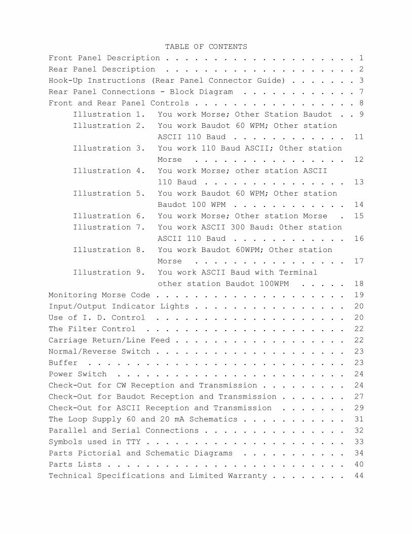
TABLE OF CONTENTSFront Panel Description . . . . . . . . . . . . . . . . . . . . 1Rear Panel Description . . . . . . . . . . . . . . . . . . . . 2Hook-Up Instructions (Rear Panel Connector Guide) . . . . . . . 3Rear Panel Connections - Block Diagram . . . . . . . . . . . . 7Front and Rear Panel Controls . . . . . . . . . . . . . . . . . 8
Illustration 1. You work Morse; Other Station Baudot . . 9Illustration 2. You work Baudot 60 WPM; Other station
ASCII 110 Baud . . . . . . . . . . . . 11Illustration 3. You work 110 Baud ASCII; 0ther station
Morse . . . . . . . . . . . . . . . . 12Illustration 4. You work Morse; other station ASCII
110 Baud . . . . . . . . . . . . . . . 13Illustration 5. You work Baudot 60 WPM; Other station
Baudot 100 WPM . . . . . . . . . . . . 14Illustration 6. You work Morse; Other station Morse . 15Illustration 7. You work ASCII 300 Baud: 0ther station
ASCII 110 Baud . . . . . . . . . . . . 16Illustration 8. You work Baudot 60WPM; Other station
Morse . . . . . . . . . . . . . . . . 17Illustration 9. You work ASCII Baud with Terminal
other station Baudot 100WPM . . . . . 18Monitoring Morse Code . . . . . . . . . . . . . . . . . . . . 19Input/Output Indicator Lights . . . . . . . . . . . . . . . . 20Use of I. D. Control . . . . . . . . . . . . . . . . . . . . 20The Filter Control . . . . . . . . . . . . . . . . . . . . . 22Carriage Return/Line Feed . . . . . . . . . . . . . . . . . . 22Normal/Reverse Switch . . . . . . . . . . . . . . . . . . . . 23Buffer . . . . . . . . . . . . . . . . . . . . . . . . . . . 23Power Switch . . . . . . . . . . . . . . . . . . . . . . . . 24Check-Out for CW Reception and Transmission . . . . . . . . . 24Check-Out for Baudot Reception and Transmission . . . . . . . 27Check-Out for ASCII Reception and Transmission . . . . . . . 29The Loop Supply 60 and 20 mA Schematics . . . . . . . . . . . 31Parallel and Serial Connections . . . . . . . . . . . . . . . 32Symbols used in TTY . . . . . . . . . . . . . . . . . . . . . 33Parts Pictorial and Schematic Diagrams . . . . . . . . . . . 34Parts Lists . . . . . . . . . . . . . . . . . . . . . . . . . 40Technical Specifications and Limited Warranty . . . . . . . . 44
1
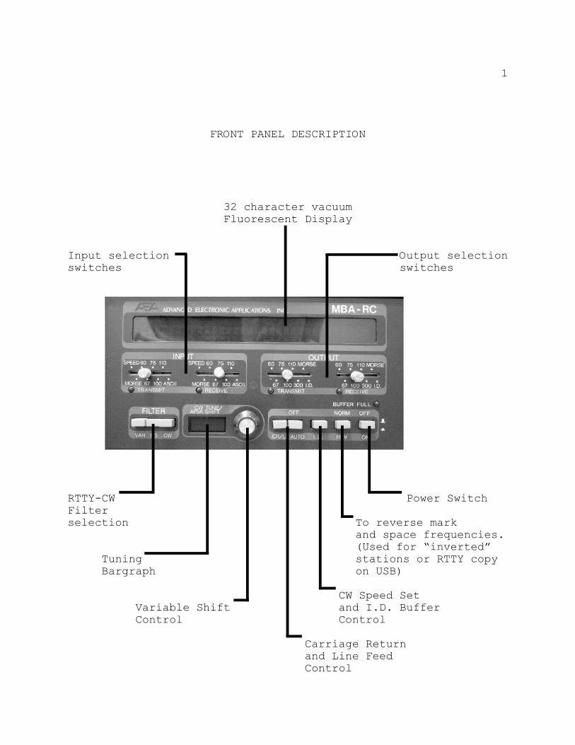
FRONT PANEL DESCRIPTION
32 character vacuumFluorescent Display
Input selection Output selectionswitches switches
RTTY-CW Power SwitchFilterselection To reverse mark
and space frequencies.(Used for “inverted”
Tuning stations or RTTY copyBargraph on USB)
CW Speed SetVariable Shift and I.D. BufferControl Control
Carriage Returnand Line FeedControl
2
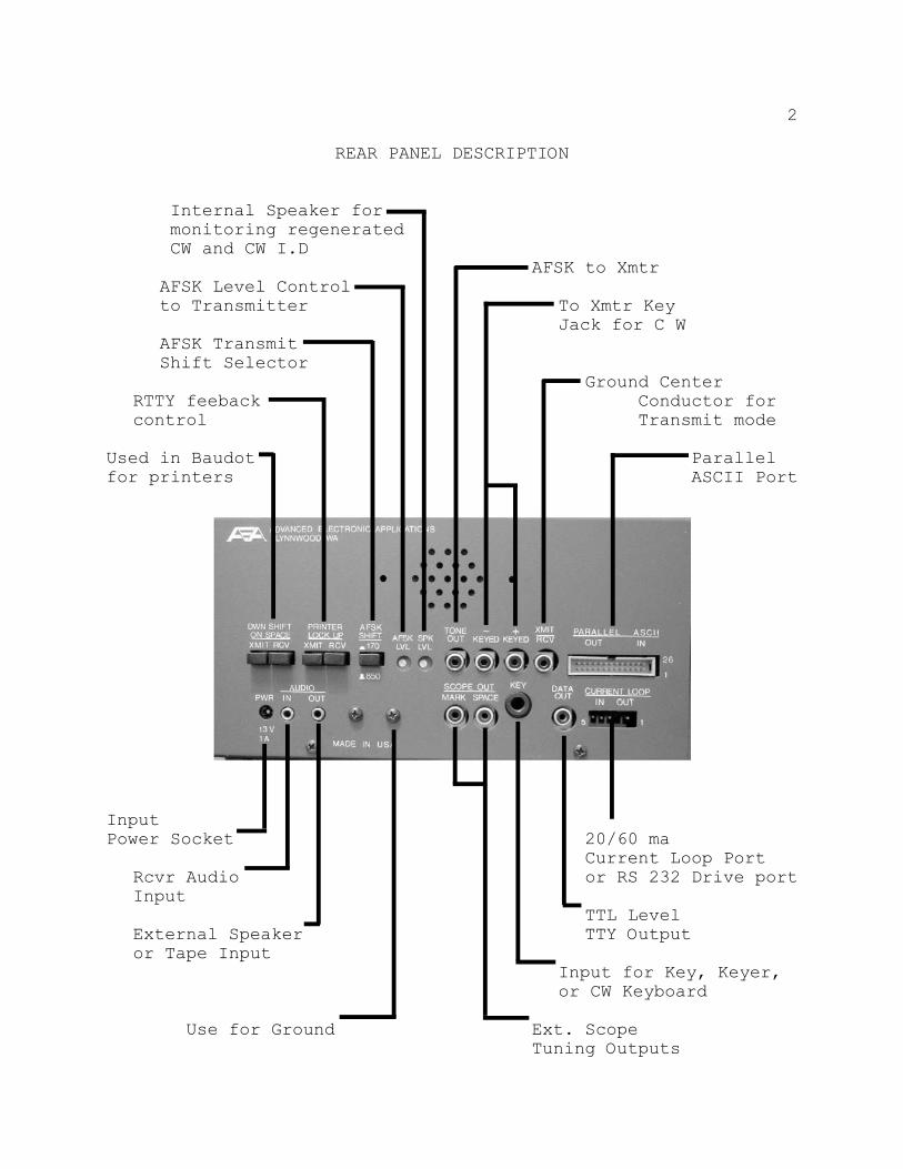
REAR PANEL DESCRIPTION
Internal Speaker for monitoring regenerated CW and CW I.D
AFSK to XmtrAFSK Level Controlto Transmitter To Xmtr Key
Jack for C WAFSK TransmitShift Selector
Ground CenterRTTY feeback Conductor forcontrol Transmit mode
Used in Baudot Parallelfor printers ASCII Port
InputPower Socket 20/60 ma
Current Loop PortRcvr Audio or RS 232 Drive portInput
TTL LevelExternal Speaker TTY Outputor Tape Input
Input for Key, Keyer,or CW Keyboard
Use for Ground Ext. ScopeTuning Outputs
3Hook Up Instructions
(Rear Panel Connectors)POWER
The MBA-RC requires a 13 ±3 VDC, well filtered power sourcecapable of supplying 1.2 amperes. The power connector is a2.1 mm center pin coaxial type, the center pin is positive.
AUDIO
The audio IN-OUT jacks are 3.5 mm phone jacks and are paralleledin the MBA-RC. The IN (input) jack is used to provide receiveraudio, CW or RTTY signals to the MBA-RC. Receiver audio canbe taken from the headphone jack or by tapping the speaker leads.The audio OUT (output) jack is provided for an external speakeror tape recorder.
KEY
The key input is a contact closure input for CW. A standard twoconductor ¼" plug is used. It may be connected to a hand key,keyer POSITIVE keyed output, or keyboard output.
SCOPE OUT
The mark and space filters output are provided at theseconnectors for tuning RTTY signals with the aid of an X-Y scope.
KEYED + AND -
The + and - keyed outputs are for CW keying of the transmitter.The + keyed output is for use with transistor and cathode keying,and the - output is for use with transmitters using blockedgrid keying.
DATA OUT
The Data Out jack is a TTL level teletype output and is activeonly in teletype modes. The output level is low during MARK.
4
CURRENT LOOP
The current loop input and output may be used with 20 or 60 mAteletype loops. Warning! The Teletype Current Loop Supply mustbe externally limited to 60 mA maximum. Optical couplersisolate the current loop input and output from the rest of theMBA-RC electronics.
PARALLEL ASCII
The parallel ASCII input and output are provided on the right andleft sides of the 26 pin parallel connector. The parallel outputis Centronics compatible parallel and may be used withCentronics, Epson and other parallel input ASCII printers. Theparallel input is seven bit ASCII, TTL Level, high true with alow true strobe.
TRANSMIT/RECEIVE
The XMIT/RCV input requires a contact closure during transmitto select the front panel transmit mode switches. This inputprovides automatic switching of the input and output modes whenswitching between transmit and receive if activated with anauxilliary set of contacts on your transmitter.
TONE OUT
The Tone Out connector is the AFSK tone output and is 2125 HzMark and 2295 Hz space on 170 Hz Shift, and 2125 Hz Mark and2975 Hz Space on 850 Hz shift. This input may be connected tothe microphone or phone patch input of your transmitter forRTTY operation. The AFSK Output Level of the AFSK tone is setwith a screwdriver at the adjustment pot.
5
TRANSMISSION OF BAUDOT-RTTY
WARNING.....WARNING.....WARNING.....WARNING.....WARNING
During RTTY transmissions your transmitter operates in a key-down mode. Most amateur transmitters can be damaged by con-tinous operation at the1r normal CW input power levels. Itwill be necessary to reduce input power when using AFSK tele-type to about 40% of the normal CW input power. Consult theOwner's Manual for the transmitter you are using.
AFSK SHIFT
The AFSK Shift push switch selects 170 Hz (In position) or850 Hz (Out position) AFSK output.
SPEAKER LEVEL
Spk Lvl set adjustment pot for CW monitor tone level.
DOWNSHIFT ON SPACE
The two Down Shift on Space switches are used for Baudot tele-type reception and transmission. With the Down Shift on Space-RCVR switch OUT, an automatic downshift is generated whena space character is received for reducing the amount ofgarbled print. To reduce transmission errors, it is recom-mended that you operate with the Down Shift on Space-Xmit switchin the IN position.
PRINTER LOCK UP
Printer Lock Up On Receive push button has two functions. Whenthe MBA-RC is used with a current loop input, the switch in theOUT position prevents input to the MBA from the keyboard whenin the receive mode. This allows local loop operation without'feedback' through the input and output of the MBA-RC.
6
PRINTER LOCK UP ON XMIT
The Printer Lock Up On Xmit push switch, when in the OUT po-sition, prevents operation of the printer by the MBA-RC whentransmitting. These two lock up functions are particularlyuseful during mode conversion operation, e.g., Baudot transmitand receive while using an ASCII teletype machine.
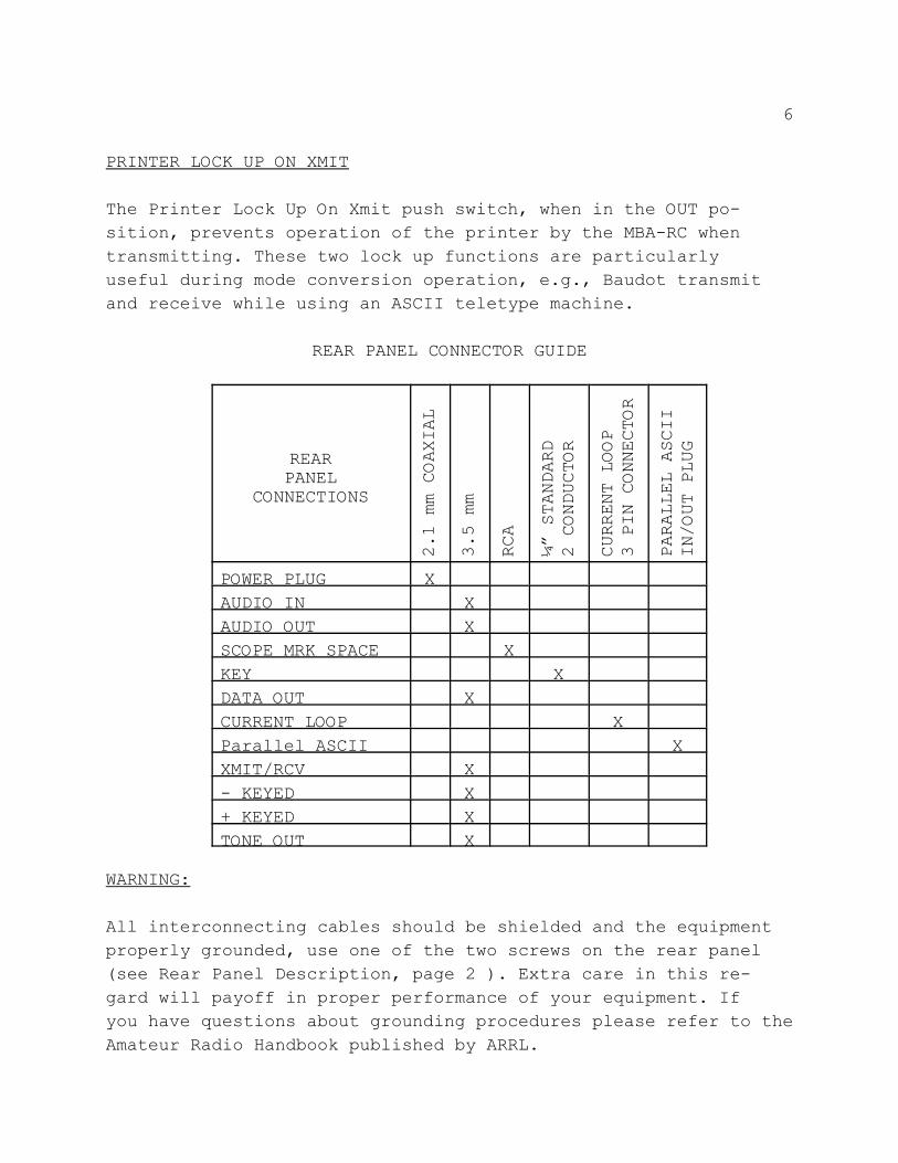
REAR PANEL CONNECTOR GUIDE
REARPANEL
CONNECTIONS
2.1 mm COAXIAL
3.5 mm
RCA
¼” STANDARD
2 CONDUCTOR
CURRENT LOOP
3 PIN CONNECTOR
PARALLEL ASCII
IN/OUT PLUG
POWER PLUG XAUDIO IN XAUDIO OUT XSCOPE MRK SPACE XKEY XDATA OUT XCURRENT LOOP XParallel ASCII XXMIT/RCV X- KEYED X+ KEYED XTONE OUT X
WARNING:
All interconnecting cables should be shielded and the equipmentproperly grounded, use one of the two screws on the rear panel(see Rear Panel Description, page 2 ). Extra care in this re-gard will payoff in proper performance of your equipment. Ifyou have questions about grounding procedures please refer to theAmateur Radio Handbook published by ARRL.
7
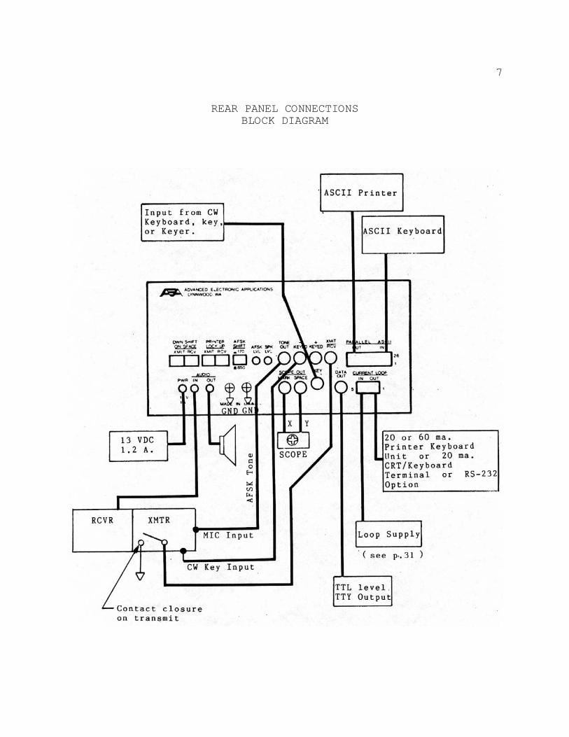
REAR PANEL CONNECTIONSBLOCK DIAGRAM
8
FRONT PANEL CONTROLS
The front panel controls may seem somewhat confusing because ofthe tremendous flexibility of the MBA-RC. Therefore it is ex-tremely important that you read and understand this sectionthoroughly.
Immediately beneath the display there are two switching areasmarked Input on the left and Output on the right. This needsexplanation since the two switches under each refer to transmitand receive. The Input refers to inputs to the MBA-RC and Outputrefers to outputs from the MBA-RC.
There are basically three ways you can transmit using theMBA-RC, CW using a hand key or paddle via a keyer, Baudot orASCII TTY using a keyboard, or TTY machine. Input is usuallyfrom two sources:
1. The station you hear via your receiver.2. Your key/keyer, keyboard, TTY machine or terminal.
For input from the receiver, the slide switch will be set on theReceive side for the mode and speed being received. For inputfrom your key/keyer, keyboard, etc. you will set the inputtransmit switch to the proper speed and mode desired.
Under the Output area there are again two switches, one fortransmit and one for receive. In this case you will be settingthe switches to do two things:
1. Set the MBA-RC to transmit a particular mode.2. Set the receive switch at the Output mode and speed
desired when receiving the other station. This is the switch used to select the proper output for generating printer hard copy of received signals.
If this is still confusing, some examples of the Input/Outputtransmit and receive switch settings are given for various modesof operation. These illustrations cover settings used in theInput and Output controls and controls on the rear panel.
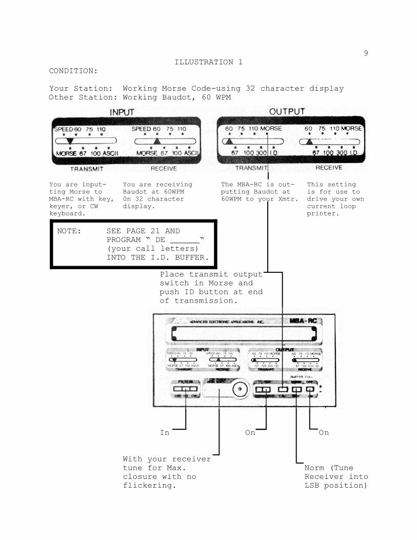
NOTE: SEE PAGE 21 ANDPROGRAM “ DE “(your call letters)INTO THE I.D. BUFFER.
9ILLUSTRATION 1
CONDITION:
Your Station: Working Morse Code-using 32 character displayOther Station: Working Baudot, 60 WPM
You are input- You are receiving The MBA-RC is out- This settingting Morse to Baudot at 60WPM putting Baudot at is for use toMBA-RC with key, 0n 32 character 60WPM to your Xmtr. drive your ownkeyer, or CW display. current loopkeyboard. printer.
Place transmit outputswitch in Morse andpush ID button at endof transmission.
In On On
With your receivertune for Max. Norm (Tuneclosure with no Receiver intoflickering. LSB position)
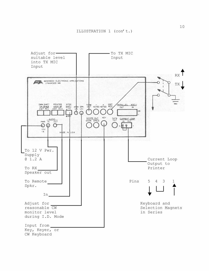
10ILLUSTRATION 1 (con’t.)
Adjust for To TX MICsuitable level Inputinto TX MICInput
•RX
TX –
To 12 V Pwr.Supply@ 1.2 A Current Loop
Output toTo RX PrinterSpeaker out
To Remote Pins 5 4 3 1Spkr. •
In –
Adjust for Keyboard andreasonable CW Selection Magnetsmonitor level in Seriesduring I.D. Mode
Input fromKey, Keyer, orCW Keyboard
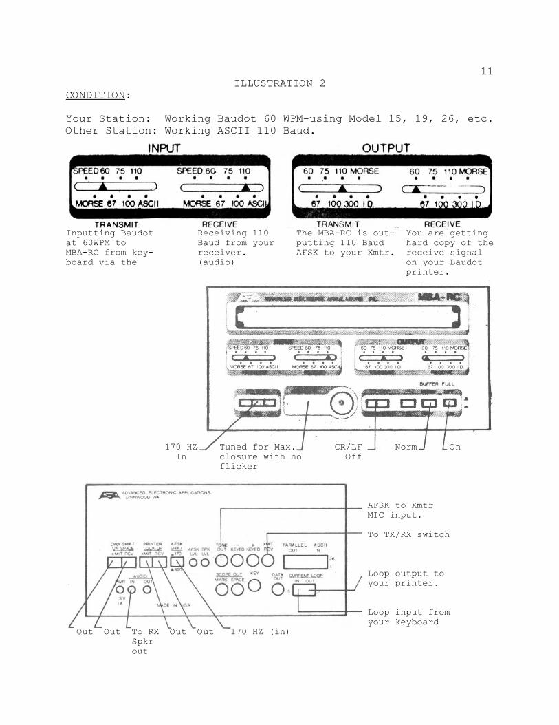
11ILLUSTRATION 2
CONDITION:
Your Station: Working Baudot 60 WPM-using Model 15, 19, 26, etc.Other Station: Working ASCII 110 Baud.
Inputting Baudot Receiving 110 The MBA-RC is out- You are gettingat 60WPM to Baud from your putting 110 Baud hard copy of theMBA-RC from key- receiver. AFSK to your Xmtr. receive signalboard via the (audio) on your Baudot
printer.
170 HZ Tuned for Max. CR/LF Norm On In closure with no Off
flicker
AFSK to Xmtr MIC input.
To TX/RX switch
Loop output to your printer.
Loop input from your keyboard
Out Out To RX Out Out 170 HZ (in)Spkrout
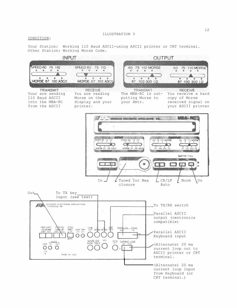
12ILLUSTRATION 3
CONDITION:
Your Station: Working 110 Baud ASCII-using ASCII printer or CRT terminal.Other Station: Working Morse Code.
Your are sending You are reading The MBA-RC is out- You receive a hard110 Baud ASCII Morse on the putting Morse to copy of Morseinto the MBA-RC display and your your Xmtr. received signal onfrom the ASCII printer. your ASCII printer
In Tuned for Max CR/LF Norm On closure Auto
Out To TX keyinput (see text)
To TX/RX switch
Parallel ASCIIoutput (centronicscompatible)
Parallel ASCIIKeyboard input
(Alternate) 20 macurrent loop out toASCII printer or CRTterminal.
(Alternate) 20 macurrent loop inputfrom Keyboard (orCRT terminal.)
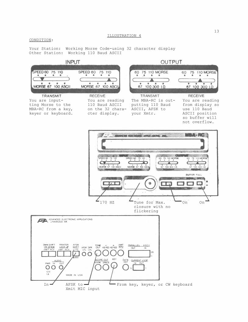
13ILLUSTRATION 4
CONDITION:
Your Station: Working Morse Code-using 32 character displayOther Station: Working 110 Baud ASCII
You are input- You are reading The MBA-RC is out- You are readingting Morse to the 110 Baud ASCII putting 110 Baud from display soMBA-RC from a key, on the 32 chara- ASCII, AFSK to use 110 Baudkeyer or keyboard. cter display. your Xmtr. ASCII position
so buffer willnot overflow.
170 HZ Tune for Max. On On closure with no flickering
In AFSK to From key, keyer, or CW keyboard Xmit MIC input
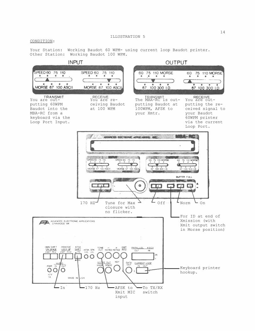
14ILLUSTRATION 5
CONDITION:
Your Station: Working Baudot 60 WPM- using current loop Baudot printer.Other Station: Working Baudot 100 WPM.
You are out- You are re- The MBA-RC is out- You are out-putting 60WPM ceiving Baudot putting Baudot at putting the re-Baudot into the at 100 WPM 100WPM, AFSK to ceived signal toMBA-RC from a your Xmtr. your Baudotkeyboard via the 60WPM printerLoop Port Input. via the current
Loop Port.
170 HZ Tune for Max Off Norm Onclosure withno flicker.
For ID at end ofXmission (withXmit output switchin Morse position)
Keyboard printerhookup.
In 170 Hz AFSK to To TX/RX Xmit MIC switch input

15ILLUSTRATION 6
CONDITION:
Your Station: Working Morse-using 32 character display.Other Station: Working Morse
You are output- You are reading With no input Can use key in-ting Morse into Morse from 32 in transmit mode, put to MBA-RCXmtr direct from character display. any position to set lowerkeyer, any posi- will do. Morse speed thattion will do. is regenerated
with internalspeaker
In Tuned for Max. Off On closure
From RX speaker output
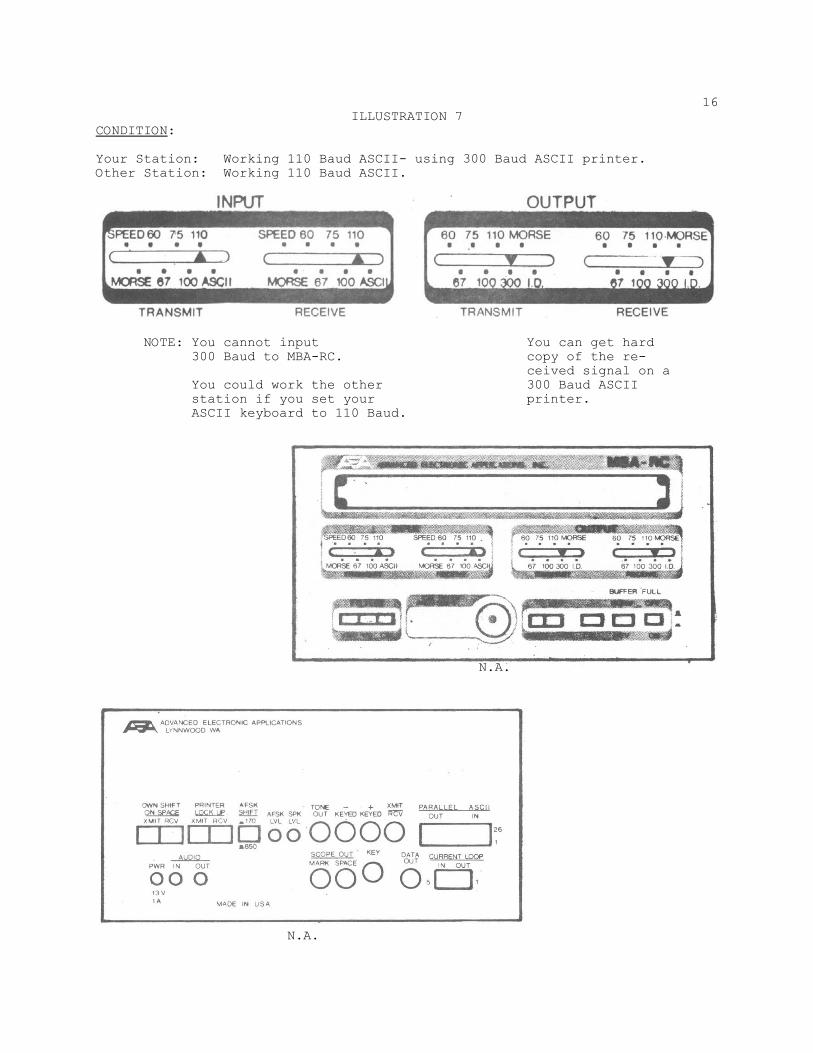
16ILLUSTRATION 7
CONDITION:
Your Station: Working 110 Baud ASCII- using 300 Baud ASCII printer.Other Station: Working 110 Baud ASCII.
NOTE: You cannot input You can get hard300 Baud to MBA-RC. copy of the re-
ceived signal on aYou could work the other 300 Baud ASCIIstation if you set your printer.ASCII keyboard to 110 Baud.
N.A.
N.A.
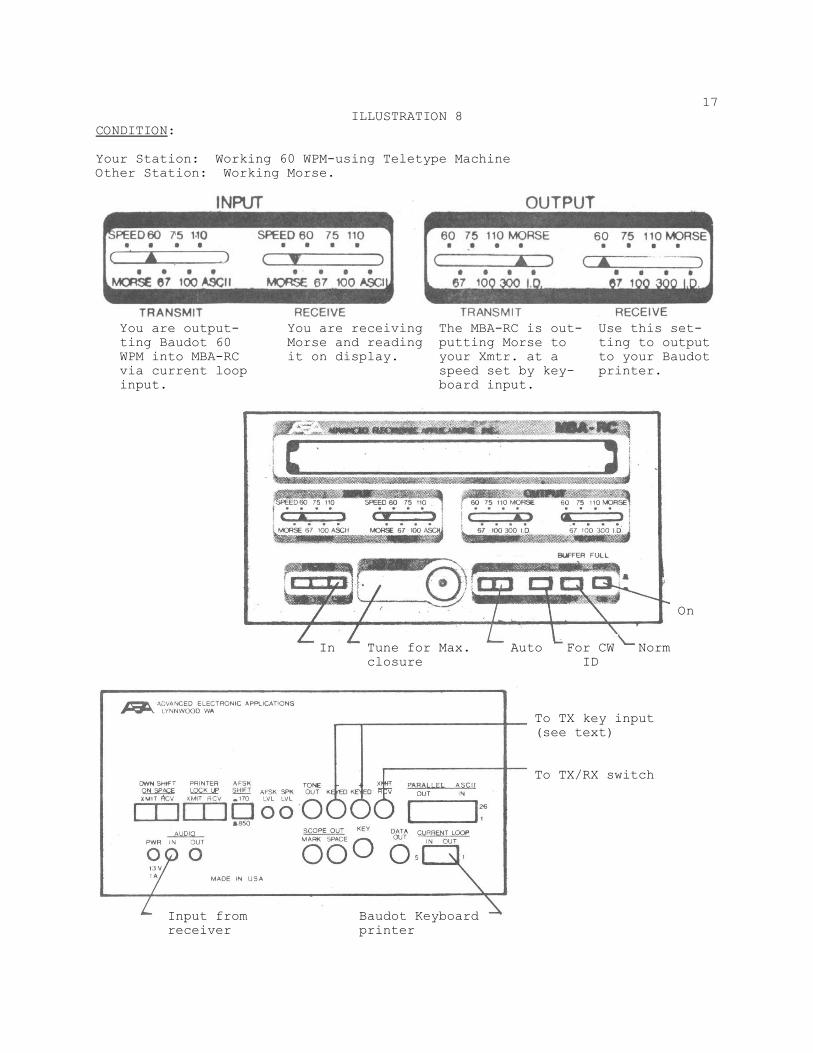
17ILLUSTRATION 8
CONDITION:
Your Station: Working 60 WPM-using Teletype MachineOther Station: Working Morse.
You are output- You are receiving The MBA-RC is out- Use this set-ting Baudot 60 Morse and reading putting Morse to ting to outputWPM into MBA-RC it on display. your Xmtr. at a to your Baudotvia current loop speed set by key- printer.input. board input.
On
In Tune for Max. Auto For CW Norm closure ID
To TX key input (see text)
To TX/RX switch
Input from Baudot Keyboardreceiver printer
AEARS-232
Video terminaland keyboard
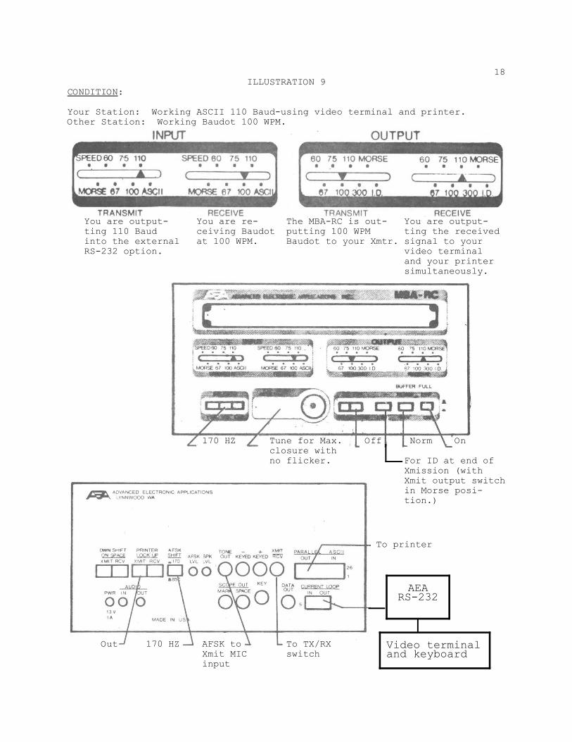
18ILLUSTRATION 9
CONDITION:
Your Station: Working ASCII 110 Baud-using video terminal and printer.Other Station: Working Baudot 100 WPM.
You are output- You are re- The MBA-RC is out- You are output-ting 110 Baud ceiving Baudot putting 100 WPM ting the receivedinto the external at 100 WPM. Baudot to your Xmtr. signal to yourRS-232 option. video terminal
and your printersimultaneously.
170 HZ Tune for Max. Off Norm Onclosure withno flicker. For ID at end of
Xmission (withXmit output switchin Morse posi-tion.)
To printer
Out 170 HZ AFSK to To TX/RXXmit MIC switchinput
19
Review these illustrations until you can quickly set up theMBA-RC for the type of contact you wish to make.
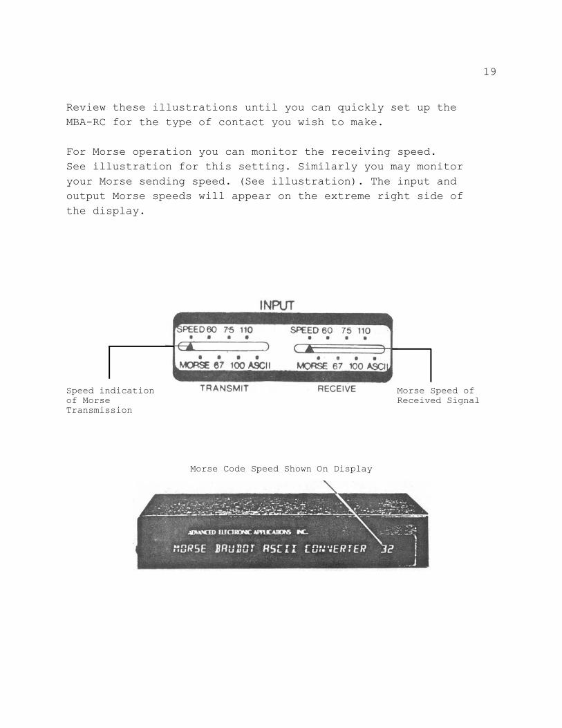
For Morse operation you can monitor the receiving speed.See illustration for this setting. Similarly you may monitoryour Morse sending speed. (See illustration). The input andoutput Morse speeds will appear on the extreme right side ofthe display.
Speed indication Morse Speed ofof Morse Received SignalTransmission
Morse Code Speed Shown On Display
20
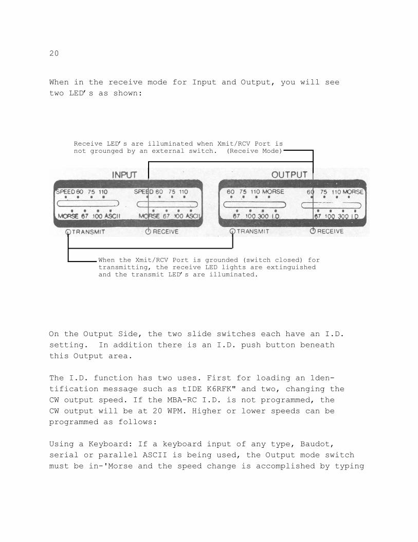
When in the receive mode for Input and Output, you will seetwo LED’s as shown:
Receive LED’s are illuminated when Xmit/RCV Port isnot grounged by an external switch. (Receive Mode)
When the Xmit/RCV Port is grounded (switch closed) fortransmitting, the receive LED lights are extinguishedand the transmit LED’s are illuminated.
On the Output Side, the two slide switches each have an I.D.setting. In addition there is an I.D. push button beneaththis Output area.
The I.D. function has two uses. First for loading an 1den-tification message such as tIDE K6RFK" and two, changing theCW output speed. If the MBA-RC I.D. is not programmed, theCW output will be at 20 WPM. Higher or lower speeds can beprogrammed as follows:
Using a Keyboard: If a keyboard input of any type, Baudot,serial or parallel ASCII is being used, the Output mode switchmust be in-'Morse and the speed change is accomplished by typing
21
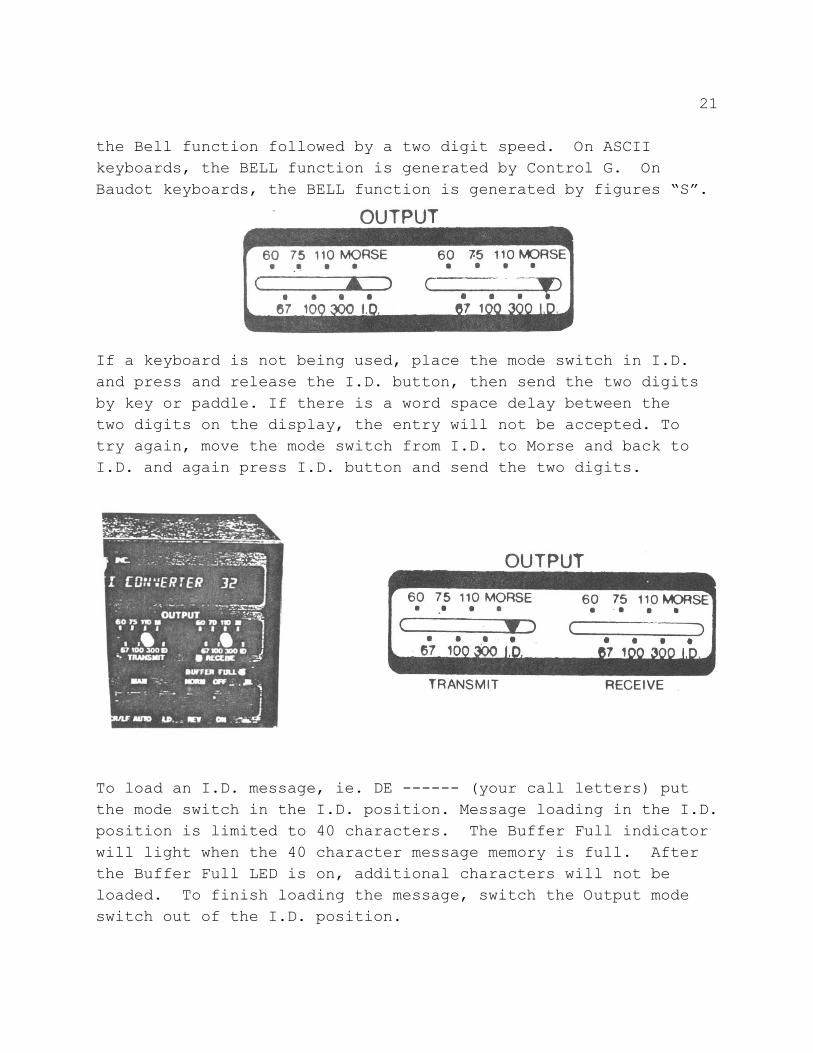
the Bell function followed by a two digit speed. On ASCIIkeyboards, the BELL function is generated by Control G. OnBaudot keyboards, the BELL function is generated by figures “S”.
If a keyboard is not being used, place the mode switch in I.D.and press and release the I.D. button, then send the two digitsby key or paddle. If there is a word space delay between thetwo digits on the display, the entry will not be accepted. Totry again, move the mode switch from I.D. to Morse and back toI.D. and again press I.D. button and send the two digits.
To load an I.D. message, ie. DE ------ (your call letters) putthe mode switch in the I.D. position. Message loading in the I.D.position is limited to 40 characters. The Buffer Full indicatorwill light when the 40 character message memory is full. Afterthe Buffer Full LED is on, additional characters will not beloaded. To finish loading the message, switch the Output modeswitch out of the I.D. position.
22
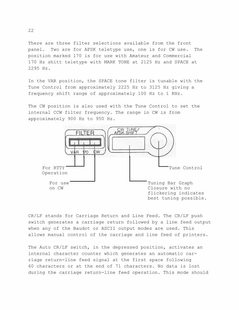
There are three filter selections available from the frontpanel. Two are for AFSK teletype use, one is for CW use. Theposition marked 170 is for use with Amateur and Commercial170 Hz shitt teletype with MARK TONE at 2125 Hz and SPACE at2295 Hz.
In the VAR position, the SPACE tone filter is tunable with theTune Control from approximately 2225 Hz to 3125 Hz giving afrequency shift range of approximately 100 Hz to 1 KHz.
The CW position is also used with the Tune Control to set theinternal CCW filter frequency. The range in CW is fromapproximately 900 Hz to 950 Hz.
For RTTY Tune ControlOperation
For use Tuning Bar Graphon CW Closure with no
flickering indicatesbest tuning possible.
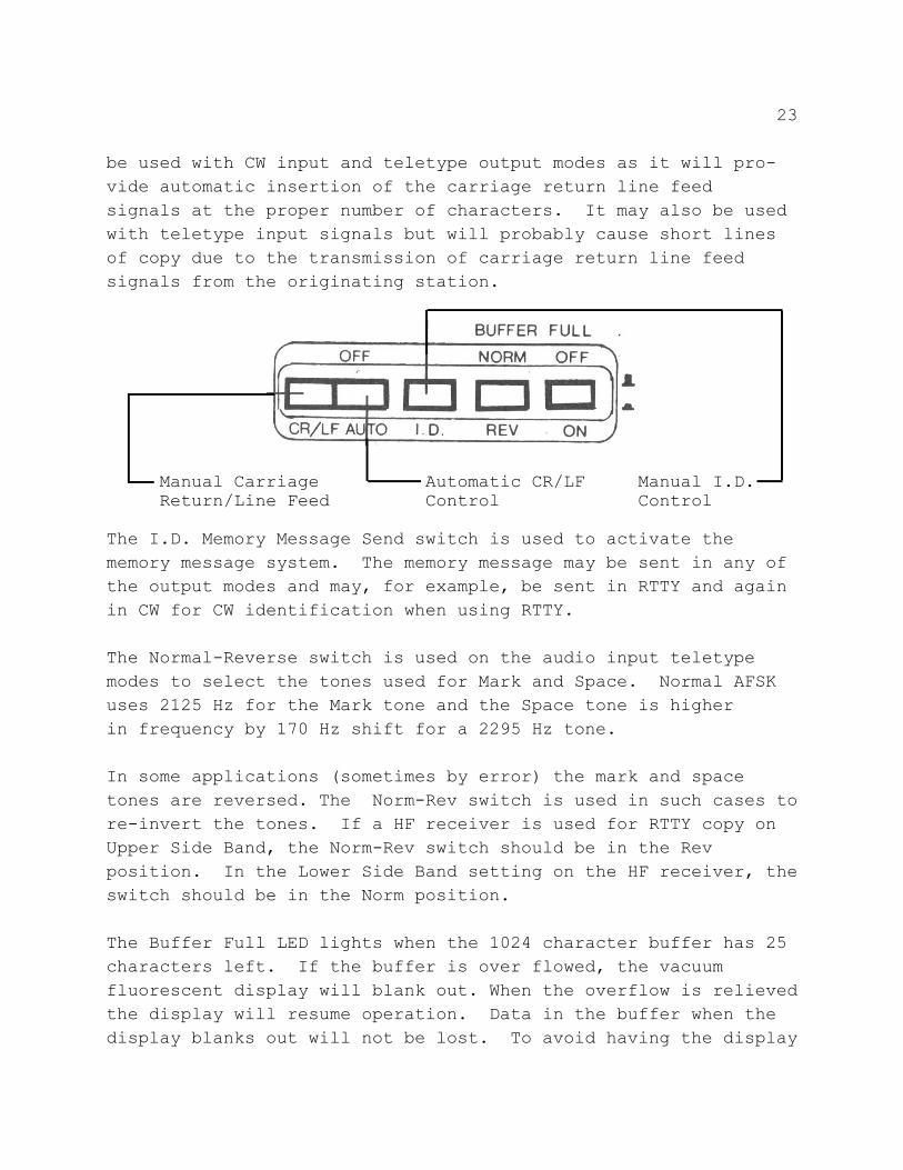
CR/LF stands for Carriage Return and Line Feed. The CR/LF pushswitch generates a carriage return followed by a line feed outputwhen any of the Baudot or ASCII output modes are used. Thisallows manual control of the carriage and line feed of printers.
The Auto CR/LF switch, in the depressed position, activates aninternal character counter which generates an automatic car-riage return-line feed signal at the first space following60 characters or at the end of 71 characters. No data is lostduring the carriage return-line feed operation. This mode should
23
be used with CW input and teletype output modes as it will pro-vide automatic insertion of the carriage return line feedsignals at the proper number of characters. It may also be usedwith teletype input signals but will probably cause short linesof copy due to the transmission of carriage return line feedsignals from the originating station.
Manual Carriage Automatic CR/LF Manual I.D.Return/Line Feed Control Control
The I.D. Memory Message Send switch is used to activate thememory message system. The memory message may be sent in any ofthe output modes and may, for example, be sent in RTTY and againin CW for CW identification when using RTTY.
The Normal-Reverse switch is used on the audio input teletypemodes to select the tones used for Mark and Space. Normal AFSKuses 2125 Hz for the Mark tone and the Space tone is higherin frequency by 170 Hz shift for a 2295 Hz tone.
In some applications (sometimes by error) the mark and spacetones are reversed. The Norm-Rev switch is used in such cases tore-invert the tones. If a HF receiver is used for RTTY copy onUpper Side Band, the Norm-Rev switch should be in the Revposition. In the Lower Side Band setting on the HF receiver, theswitch should be in the Norm position.
The Buffer Full LED lights when the 1024 character buffer has 25characters left. If the buffer is over flowed, the vacuumfluorescent display will blank out. When the overflow is relievedthe display will resume operation. Data in the buffer when thedisplay blanks out will not be lost. To avoid having the display
24
blank out during normal operation, if no output device is beingused, it is a good practice to leave the receive output switch inthe 300 Baud ASCII position to avoid inadvertent filling of thebuffer. Also, the Buffer Full LED is used with the I.D. memorymessage unit. It will light when more than 40 characters havebeen entered. The first 40 characters will be loaded in the I.D.memory. Characters sent after the Buffer Full LED is illumi-nated will not be loaded.The On/Off push button controls the power to the MBA-RC.
CHECK OUT PROCEDURE
RECEPTION OF CW
1. Be sure the MBA-RC is set up with the proper supply, 10 toVDC at 1.2 amperes.
2. Have audio from either your receiver's headphone jack orfrom your speaker leads and have the Audio In inputconnection made to the MBA-RC.
3. With your receiver, tune in a strong CW signal with goodfist quality.
4. Turn MBA-RC power On. The display should be illuminated.5. On the receive input section: slide the switch to Morse.6. Set the Filter to CW and with the receiver frequency tuning
control, tune for maximum closure of the Bar Graph. Thisshould cause the copy to appear on the 32 character displayand progress from right to left across the panel. The MBA-RCTune Control can be used for fine tuning.
If you make any but the finest adjustment in the receiver tuning,you will lose the copy on the 32 character display. It will benecessary to re-tune to retrieve the copy. If your receiver hasCW filtering, switching in or out of the filters may also because for receiver and MBA-RC re-tuning.
Be sure your receiver has been turned on long enough to assure
25
good frequency stability. An unstable receiver will result inloss of CW copy due to frequency drift. You will find that areceiver noise blanker can be most useful at times when copyingCW in the presence of noise spikes.
The MBA-RC will do a good job of copying signals with QRM. Withyour receiver, tune to a frequency where there is some QRM andisolate a CW signal. Using the above tuning procedure tune foreffective copy on the MBA-RC display. You will note that withcareful tuning you can obtain copy. When excessive noise orstatic is present the MBA-RC microcomputer will read these asE's and T's and they will appear on the display.
Practice the tuning of a CW signal until you can obtain goodcopy under a variety of receiving conditions.
If you have never before used a computerized Morse code copyingunit, you may initially be disappointed because solid copy isnot the rule. The MBA-RC should perform as well as, or betterthan, most all other Morse code readers on the market.
In general, you will note the following:
1. Many slow speed signals on the air are accompanied by sloppyfists. Quite often, the faster the station's sending, thebetter his fist.
2. At speeds within your own ability to copy, the reader willnot perform as well as your own brain, particularly whennoise spikes are as strong, or stronger than, the signal orwhen the signal is sent with a sloppy fist.
3. Sometimes a slow AGC will be better than fast AGC andvice versa, depending on your receiver.
4. The MBA-RC Morse reading function is most useful for teaching you to copy code at a higher speed than you wouldnormally copy comfortably. The large 32 character displayallows you to “piece together” what would otherwise be
26
poor copy.5. The MBA-RC is very useful for those operators who cannot
seem to copy code without a pencil and paper. After suffi-cient practice using the MBA-RC, copying CW in your headwill become second nature.
6. Probably one of the biggest uses for the MBA-RC in CW modeis in monitoring your own transmitted fist as it goes outover the air. Many operators are surprised to learn justhow sloppy their automatic keyer generated CW can be. Thisis normally a result of improper spacing between charactersand words.
7. The symbol is an indication of an invalid characterthat is seven elements or less in length. Any invalidcharacter of seven elements or more in length is simplyignored by the reader.
8. You will note that the MBA-RC copies RTTY much better thanCW. This is due to the inherent noise rejection featuresof RTTY operation.
TRANSMISSION OF CW
Transmission of CW would normally be accomplished by using aBaudot or ASCII keyboard. It is possible to use a hand key orelectronic keyer as an input and use the MBA-RC to change thespeed, but that is really impractical. From the rear panel ofthe MBA-RC, make the correct connection from the keying out port.For a cathode keyed transmitter and most transistor rigs, use the+ keyed output. For blocked grid keyed transmitters use the- keyed output.
Be sure the Transmit/Receive switch is operable. You may use anexternal toggle switch or a transmit relay contact closure onyour transceiver.Refer to Illustration 6 for the proper front and rear panelswitch settings.
27
KEYING PROCEDURE
1. If using separate receiver and transmitter be sure you arezero beat with the receiver frequency and you have a clearfrequency.
2. Effect closure of the Transmit/Receive switch.3. Key the transmitter, with your selected method.4. Using accepted operating procedures either call CQ or
respond to a calling station. Upon completion of your call,if using an external switch, be sure you are in the receivemode.
5. You should have been able to visually monitor yourtransmission on the 32 character display.
6. Proceed with your QSO, observing the display in bothtransmit and receive modes.
RECEPTION OF BAUDOT - RTTY
Please study Illustration 5 for the correct connections on therear panel of the MBA-RC.
1. With your receiver, tune in a strong RTTY signal. Be sureyour receiver is set at LSB, and tune to the high audiotone side of the RTTY signal.
2. Apply power to the MBA-RC, the 32 character display shouldbe illuminated.
3. With your receiver, tune to the lowest tone frequencyup through the RTTY signal until the Bar Graph on the MBA-RCreaches maximum closure, but flickers on and off with thesignal. Then tune for maximum closure of the Bar Graph on aslightly lower frequency with no or only minimum flicker.The two peaks are close together, it is important to be ableto tune right to the one that causes no flicker of theBar Graph.
4. Minor adjustments can be made to the receiver tuning to peakup copy if the receiver or transmitter frequencies aredrifting.
28
Practice tuning a RTTY signal so you can achieve good copy in aminimum of time. If you experience difficulty tuning RTTY followthe steps outlined here:
A. Be sure all switch settings are as shown in Illustration 5.B. Make sure all rear panel connections are correctly made.C. Try selecting a different speed, e.g. 60-67-75-100 to
ascertain you are tuned to the right speed. Most amateurRTTY is at 60 WPM.
D. If copy is garbled, push the Norm/Rev switch in. If theoriginating station is transmitting in Reverse mode thecopy will be garbage.
E. Switch the Filter to Var (variable) in case the originatingstation is using something different than 170 Hz shift.When you switch to Var you will need to re-tune the BarGraph for maximum closure.
F. The 2125 - 2295 Hz tones used for most RTTY is a higherpitch than most CW operators are used to. If yourtransceiver has passband tuning of I.F. Shift, be sure bothcontrols are properly centered.
G. If you have an X -Y oscilloscope, you can connect it to thescope output jacks on the rear panel of the MBA-RC forprecise tuning. The ARRL Amateur Radio Handbook is anexcellent reference source for more information on RTTY.
If none of these remedial moves clears up the problem, don'tdispair. If you are copying Commercial RTTY you should know thatmuch of their transmission is encrypted so you cannot interceptthe copy (especially much of the news service RTTY).
TRANSMISSION OF BAUDOT - RTTY
WARNING.....WARNING.....WARNING.....WARNING.....WARNING.....WARNING
During RTTY transmissions your transmitter operates in a key-down mode. Most amateur transmitters can be damaged by con-tinous operation at their normal CW input power levels.It will be necessary to reduce input power when using AFSK
29
teletype to about 40% of the normal CW input power. Consultthe Owner's Manual for the transmitter you are using.
Study Illustration 5 for the proper rear panel control and connectionprocedures. Make sure all connections are secure. Now look at thefront panel switches. The only change will be in the Output/Transmitslide switch. Put this switch on 60.
TRANSMITTING PROCEDURE
1. If you are using a separate transmitter and receiver, be surethe transmitter is zero beat with your receiver.
2. Effect closure of the Transmit switch either manually or viaa transmitter contact closure.
3. Using your Baudot keyboard, either respond to a RTTY stationcalling CQ or initiate a CQ call. When completed be sure theT/R switch is set for receive.
4. When a station responds, carryon with the QSO per the above.5. To prevent your printer from repeating your transmissions you
should set the Xmit Printer Lock Up button into the OUT positionon the rear panel.
6. The 32 character display will be operative and show your Baudottransmissions.
RECEPTION OF ASCII - RTTY
Please study Illustration 9 carefully for the rear panel connections.If you are not using a video terminal the RS-232 option is notrequired. However, your parallel output keyboard would be connectedto the ASCII parallel input port.The tuning procedure for ASCIL is identical to the Baudot tuningprocedure. Be sure to learn the tuning by practice.
TRANSMISSION OF ASCII - RTTY
Be sure to observe the WARNING as set forth in the Baudot transmis-sion. The RTTY transmitter input should be about 40% of the normalCW input power, or the level specified in the Owner's Manual.
30
Again study Illustration 9 for the proper switch settings.Proceed to transmit, observing the same procedure as outlinedin Baudot Transmission.
IN CASE OF DIFFICULTIES
If, after re-reading this manual, you are having difficulties,a phone call to the factory Customer Service Department willlikely provide a quick answer to your problems. Before callingthe factory, try to have the MBA-RC in operation near the tele-phone so that our technician can talk you through the problems.
Our telephone number is 206-775-7373. office hours are 0800to 1630 Pacific Time Zone.
31
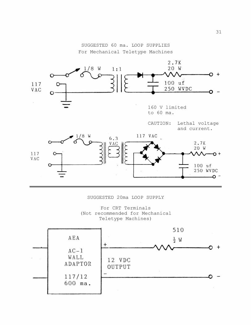
SUGGESTED 60 ma. LOOP SUPPLIESFor Mechanical Teletype Machines
160 V limitedto 60 ma.
CAUTION: Lethal voltageand current.
SUGGESTED 20ma LOOP SUPPLY
For CRT Terminals(Not recommended for Mechanical
Teletype Machines)
32
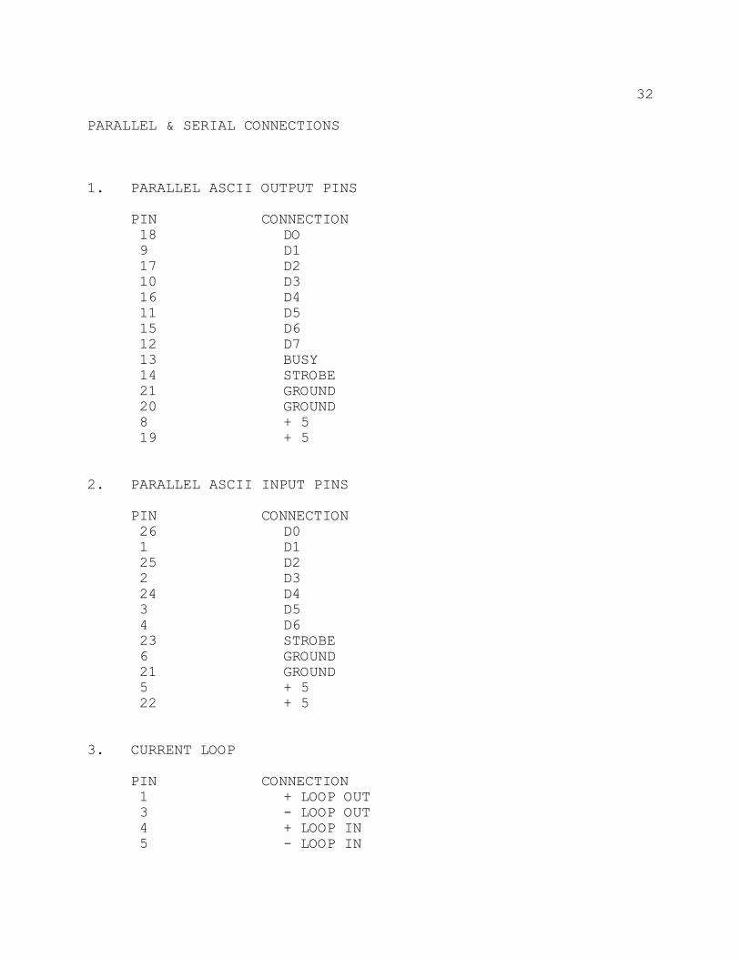
PARALLEL & SERIAL CONNECTIONS
1. PARALLEL ASCII OUTPUT PINS
PIN CONNECTION 18 DO 9 D1 17 D2 10 D3 16 D4 11 D5 15 D6 12 D7 13 BUSY 14 STROBE 21 GROUND 20 GROUND 8 + 5 19 + 5
2. PARALLEL ASCII INPUT PINS
PIN CONNECTION 26 D0 1 D1 25 D2 2 D3 24 D4 3 D5 4 D6 23 STROBE 6 GROUND 21 GROUND 5 + 5 22 + 5
3. CURRENT LOOP
PIN CONNECTION 1 + LOOP OUT 3 - LOOP OUT 4 + LOOP IN 5 - LOOP IN
33
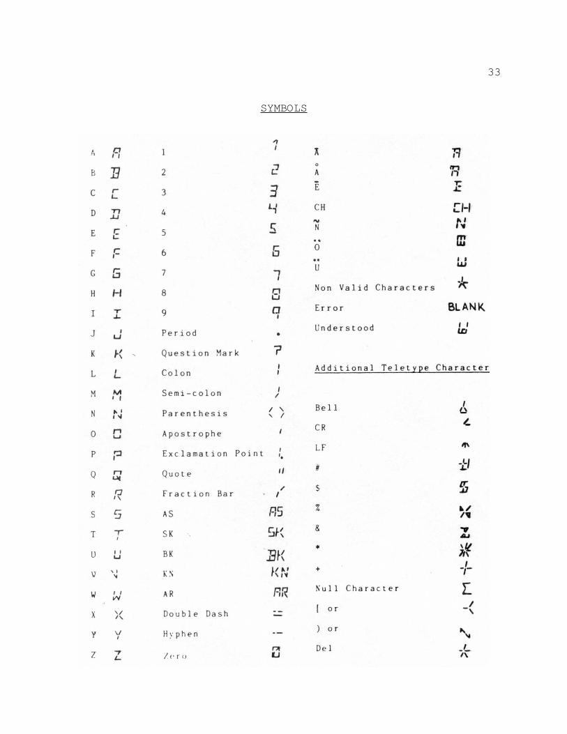
SYMBOLS
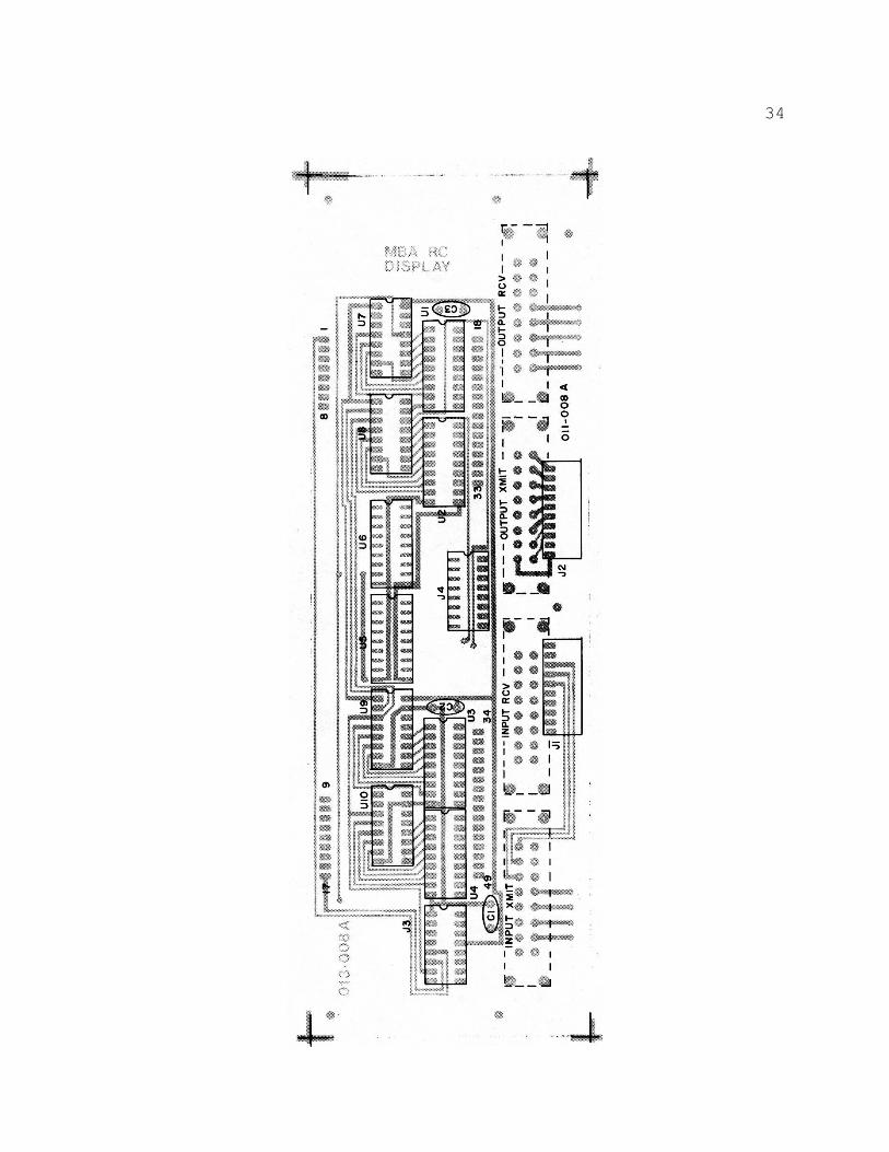
34
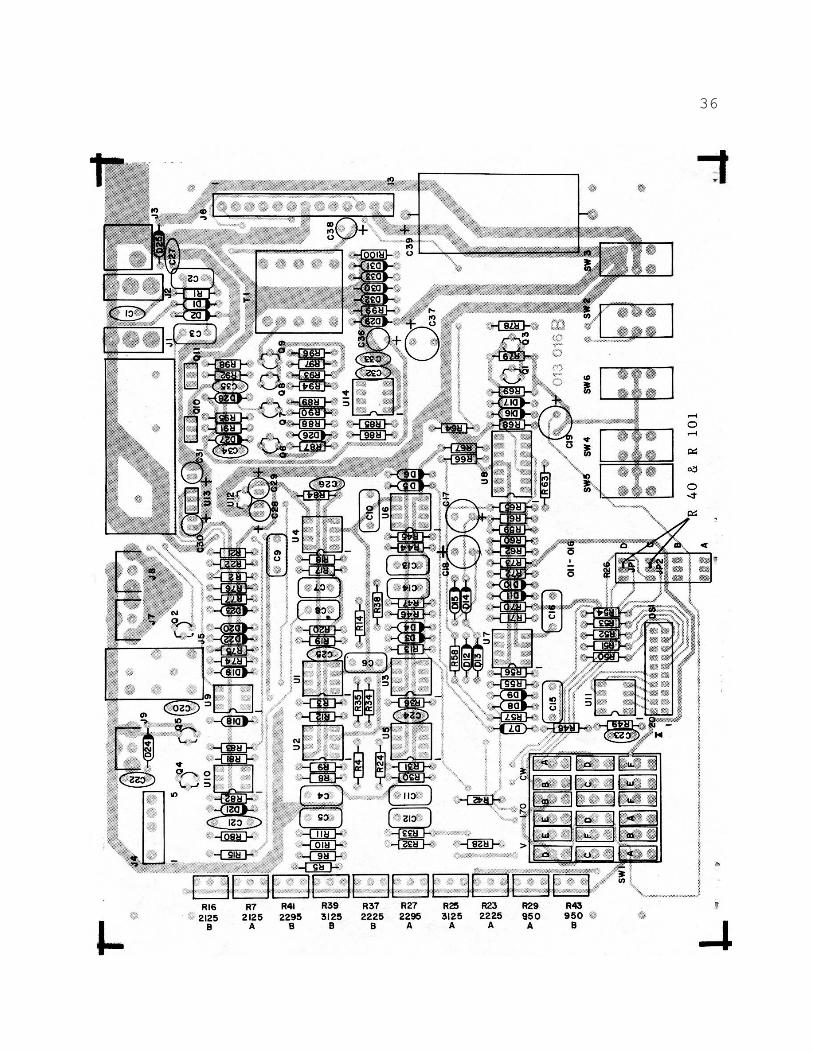
35
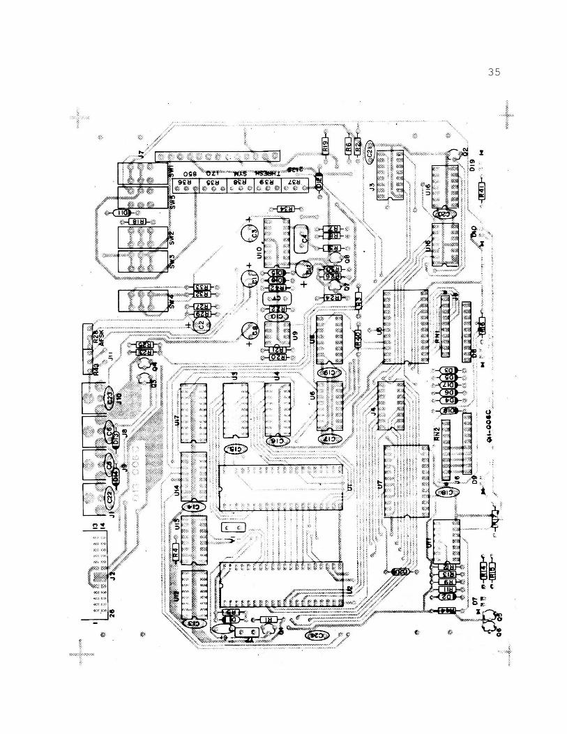
36
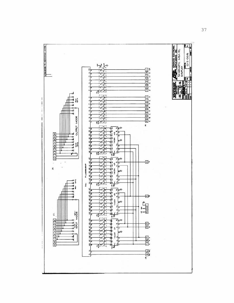
37
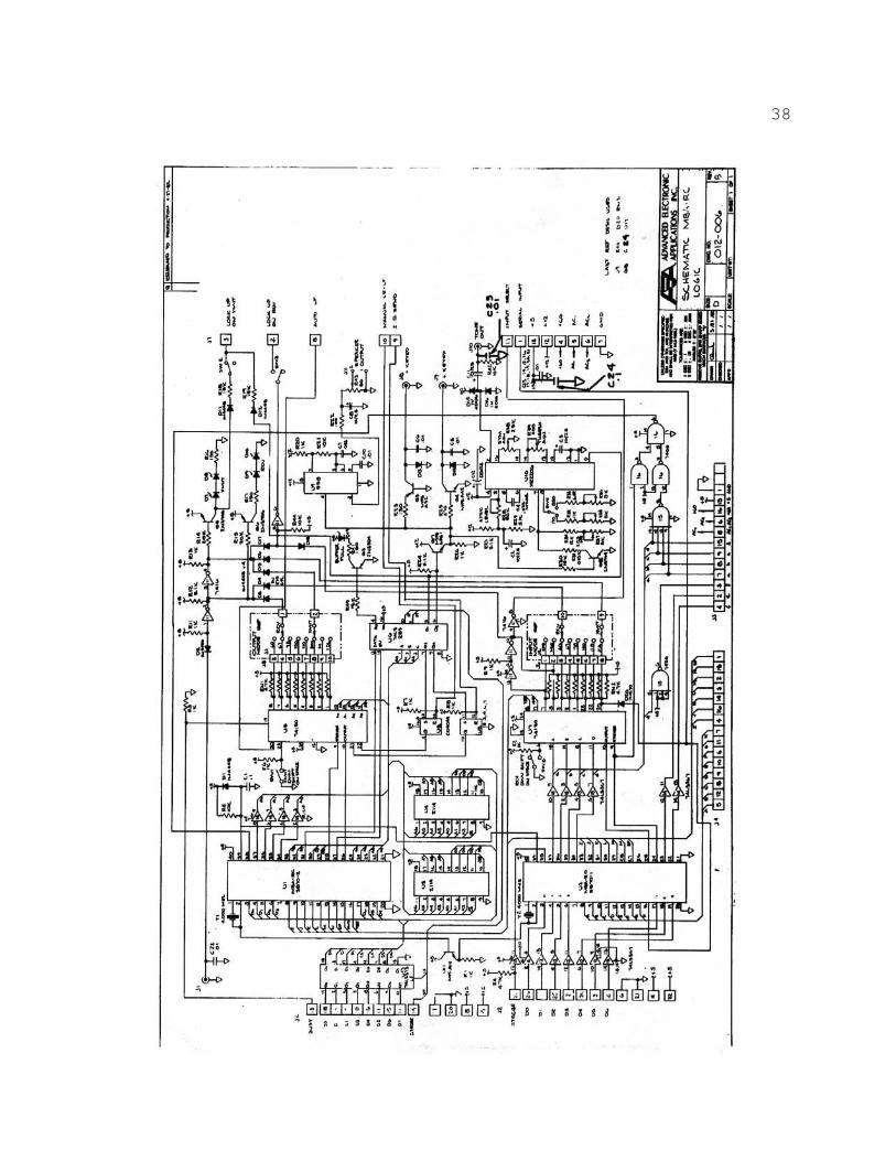
38
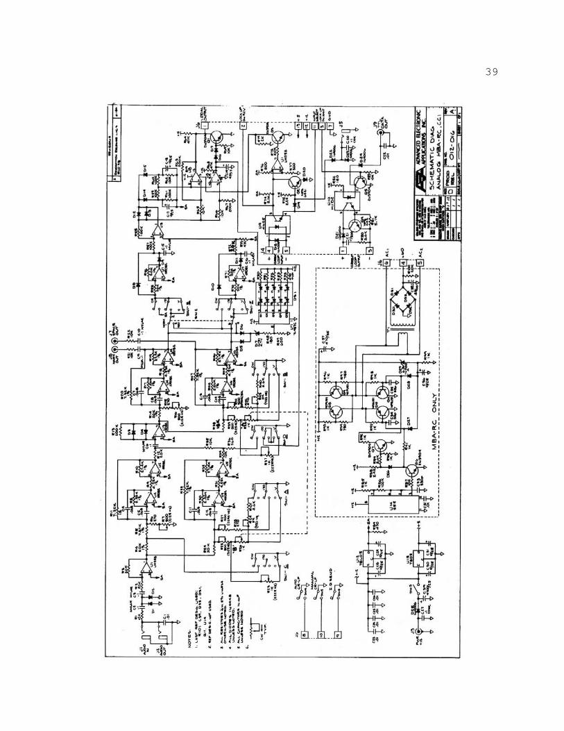
39
40
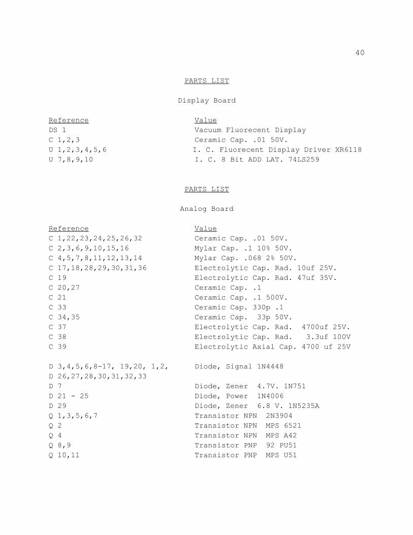
PARTS LIST
Display Board
Reference ValueDS 1 Vacuum Fluorecent DisplayC 1,2,3 Ceramic Cap. .01 50V.U 1,2,3,4,5,6 I. C. Fluorecent Display Driver XR6118U 7,8,9,10 I. C. 8 Bit ADD LAT. 74LS259
PARTS LIST
Analog Board
Reference ValueC 1,22,23,24,25,26,32 Ceramic Cap. .01 50V.C 2,3,6,9,10,15,16 Mylar Cap. .1 10% 50V.C 4,5,7,8,11,12,13,14 Mylar Cap. .068 2% 50V.C 17,18,28,29,30,31,36 Electrolytic Cap. Rad. 10uf 25V.C 19 Electrolytic Cap. Rad. 47uf 35V.C 20,27 Ceramic Cap. .1C 21 Ceramic Cap. .1 500V.C 33 Ceramic Cap. 330p .1C 34,35 Ceramic Cap. 33p 50V.C 37 Electrolytic Cap. Rad. 4700uf 25V.C 38 Electrolytic Cap. Rad. 3.3uf 100VC 39 Electrolytic Axial Cap. 4700 uf 25V
D 3,4,5,6,8-17, 19,20, 1,2, Diode, Signal 1N4448D 26,27,28,30,31,32,33D 7 Diode, Zener 4.7V. 1N751D 21 - 25 Diode, Power 1N4006D 29 Diode, Zener 6.8 V. 1N5235AQ 1,3,5,6,7 Transistor NPN 2N3904Q 2 Transistor NPN MPS 6521Q 4 Transistor NPN MPS A42Q 8,9 Transistor PNP 92 PU51Q 10,11 Transistor PNP MPS U51
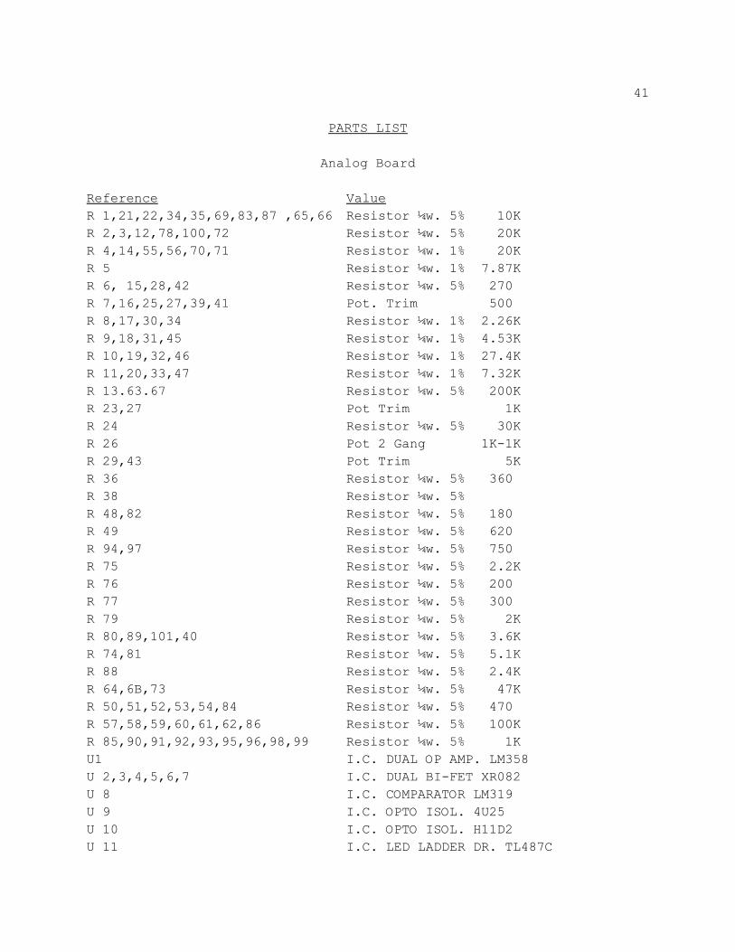
41
PARTS LIST
Analog Board
Reference ValueR 1,21,22,34,35,69,83,87 ,65,66 Resistor ¼w. 5% 10KR 2,3,12,78,100,72 Resistor ¼w. 5% 20KR 4,14,55,56,70,71 Resistor ¼w. 1% 20KR 5 Resistor ¼w. 1% 7.87KR 6, 15,28,42 Resistor ¼w. 5% 270R 7,16,25,27,39,41 Pot. Trim 500R 8,17,30,34 Resistor ¼w. 1% 2.26KR 9,18,31,45 Resistor ¼w. 1% 4.53KR 10,19,32,46 Resistor ¼w. 1% 27.4KR 11,20,33,47 Resistor ¼w. 1% 7.32KR 13.63.67 Resistor ¼w. 5% 200KR 23,27 Pot Trim 1KR 24 Resistor ¼w. 5% 30KR 26 Pot 2 Gang 1K-1KR 29,43 Pot Trim 5KR 36 Resistor ¼w. 5% 360R 38 Resistor ¼w. 5%R 48,82 Resistor ¼w. 5% 180R 49 Resistor ¼w. 5% 620R 94,97 Resistor ¼w. 5% 750R 75 Resistor ¼w. 5% 2.2KR 76 Resistor ¼w. 5% 200R 77 Resistor ¼w. 5% 300R 79 Resistor ¼w. 5% 2KR 80,89,101,40 Resistor ¼w. 5% 3.6KR 74,81 Resistor ¼w. 5% 5.1KR 88 Resistor ¼w. 5% 2.4KR 64,6B,73 Resistor ¼w. 5% 47KR 50,51,52,53,54,84 Resistor ¼w. 5% 470R 57,58,59,60,61,62,86 Resistor ¼w. 5% 100KR 85,90,91,92,93,95,96,98,99 Resistor ¼w. 5% 1KU1 I.C. DUAL OP AMP. LM358U 2,3,4,5,6,7 I.C. DUAL BI-FET XR082U 8 I.C. COMPARATOR LM319U 9 I.C. OPTO ISOL. 4U25U 10 I.C. OPTO ISOL. H11D2U 11 I.C. LED LADDER DR. TL487C
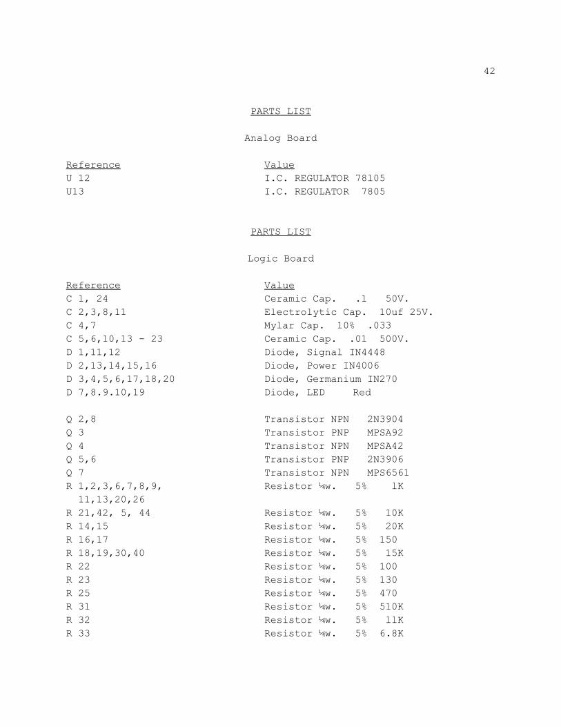
42
PARTS LIST
Analog Board
Reference ValueU 12 I.C. REGULATOR 78l05U13 I.C. REGULATOR 7805
PARTS LIST
Logic Board
Reference ValueC 1, 24 Ceramic Cap. .1 50V.C 2,3,8,11 Electrolytic Cap. 10uf 25V.C 4,7 Mylar Cap. 10% .033C 5,6,10,13 - 23 Ceramic Cap. .01 500V.D 1,11,12 Diode, Signal IN4448D 2,13,14,15,16 Diode, Power IN4006D 3,4,5,6,17,18,20 Diode, Germanium IN270D 7,8.9.10,19 Diode, LED Red
Q 2,8 Transistor NPN 2N3904Q 3 Transistor PNP MPSA92Q 4 Transistor NPN MPSA42Q 5,6 Transistor PNP 2N3906Q 7 Transistor NPN MPS6561R 1,2,3,6,7,8,9, Resistor ¼w. 5% lK 11,13,20,26R 21,42, 5, 44 Resistor ¼w. 5% 10KR 14,15 Resistor ¼w. 5% 20KR 16,17 Resistor ¼w. 5% 150R 18,19,30,40 Resistor ¼w. 5% 15KR 22 Resistor ¼w. 5% 100R 23 Resistor ¼w. 5% 130R 25 Resistor ¼w. 5% 470R 31 Resistor ¼w. 5% 510KR 32 Resistor ¼w. 5% llKR 33 Resistor ¼w. 5% 6.8K
43
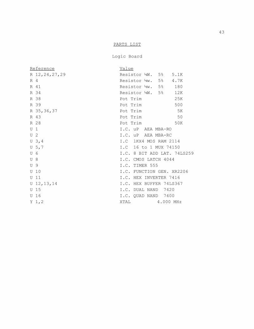
PARTS LIST
Logic Board
Reference ValueR 12,24,27,29 Resistor ¼W. 5% 5.1KR 4 Resistor ¼w. 5% 4.7KR 41 Resistor ¼w. 5% 180R 34 Resistor ¼W. 5% 12KR 38 Pot Trim 25KR 39 Pot Trim 500R 35,36,37 Pot Trim 5KR 43 Pot Trim 50R 28 Pot Trim 50KU 1 I.C. uP AEA MBA-ROU 2 I.C. uP AEA MBA-RCU 3,4 I.C lKX4 MOS RAM 2114U 5,7 I.C 16 to 1 MUX 74150U 6 I.C. 8 BIT ADD LAT. 74LS259U 8 I.C. CMOS LATCH 4044U 9 I.C. TIMER 555U 10 I.C. FUNCTION GEN. XR2206U 11 I.C. HEX INVERTER 7416U 12,13,14 I.C. HEX BUFFER 74LS367U 15 I.C. DUAL NAND 7420U 16 I.C. QUAD NAND 7400Y 1,2 XTAL 4.000 MHz
44
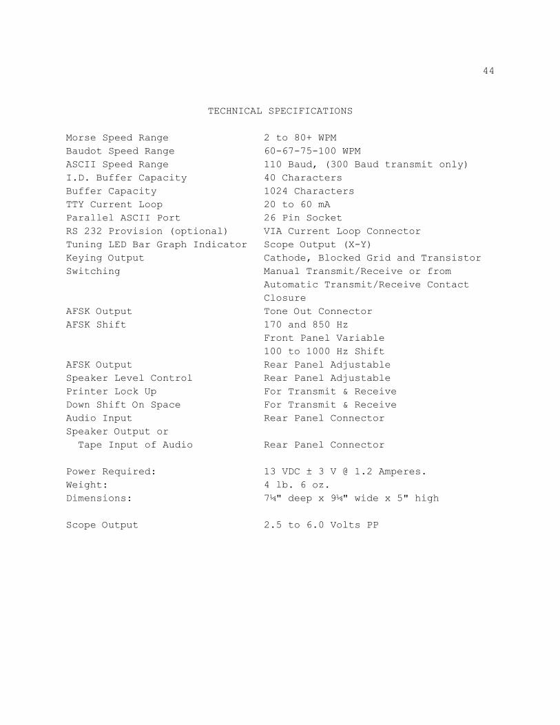
TECHNICAL SPECIFICATIONS
Morse Speed Range 2 to 80+ WPMBaudot Speed Range 60-67-75-100 WPMASCII Speed Range 110 Baud, (300 Baud transmit only)I.D. Buffer Capacity 40 CharactersBuffer Capacity 1024 CharactersTTY Current Loop 20 to 60 mAParallel ASCII Port 26 Pin SocketRS 232 Provision (optional) VIA Current Loop ConnectorTuning LED Bar Graph Indicator Scope Output (X-Y)Keying Output Cathode, Blocked Grid and TransistorSwitching Manual Transmit/Receive or from
Automatic Transmit/Receive ContactClosure
AFSK Output Tone Out ConnectorAFSK Shift 170 and 850 Hz
Front Panel Variable100 to 1000 Hz Shift
AFSK Output Rear Panel AdjustableSpeaker Level Control Rear Panel AdjustablePrinter Lock Up For Transmit & ReceiveDown Shift On Space For Transmit & ReceiveAudio Input Rear Panel ConnectorSpeaker Output or Tape Input of Audio Rear Panel Connector
Power Required: 13 VDC ± 3 V @ 1.2 Amperes.Weight: 4 lb. 6 oz.Dimensions: 7¼" deep x 9¼" wide x 5" high
Scope Output 2.5 to 6.0 Volts PP
45
LIMITED WARRANTY
ADVANCED ELECTRONIC APPLICATIONS, INC. warrants to the original purchaserthat this product shall be free from defects in material or workmanship for ninety daysfrom the date of original purchase. In order to obtain warranty service: (1) Completeand mail the warranty registration card to Advanced Electronic Applications, Inc., and(2) Send written notification to the address below as soon as possible after discoveringa possible defect: Advanced Electronic Applications, Inc.
Attention: Service Department2006 -196th S.W.
Lynnwood, Wa. 98036 The written notification must include a copy of the invoice. Include a description of thedefective part or condition, with details of the electrical connections to associatedequipment and list such equipment. Please enclose your name, phone number, andaddress. Shipping charges for any parts or units submitted for replacement under thiswarranty must be paid by the purchaser. Correct maintenance, repair, and use are important to insure proper performance fromthis product. Carefully read the Instruction Manual. This warranty does not apply to anydefect AEA determines is caused by ( 1) improper maintenance or repair, including theinstallation of parts or accessories that do not conform to the quality and specificationof the original parts; (2) misuse, abuse, neglect, or improper installation; (3) accidentalor intentional damage. All implied warranties, if any, terminate ninety days from the date of original purchase.AEA is not responsible for damage to other equipment or property or any otherconsequential or incidental damage of any kind whether based on contract, negligence,or strict liability. Maximum liability shall not, in any case, exceed the purchase price ofthe unit. The foregoing constitutes AEAs entire obligation with respect to this product. Theoriginal purchaser and any user or owner shall have no other remedy and no claim forincidental or consequential damages. Some states do not allow limitations on how longan implied warranty lasts or do not allow the exclusion of incidental or consequentialdamages, therefore, the above limitations and exclusions may not apply to you. This warranty gives specific legal rights. You may also have other rights which varyfrom state to state.