Embed Size (px)
Citation preview
3005-0011
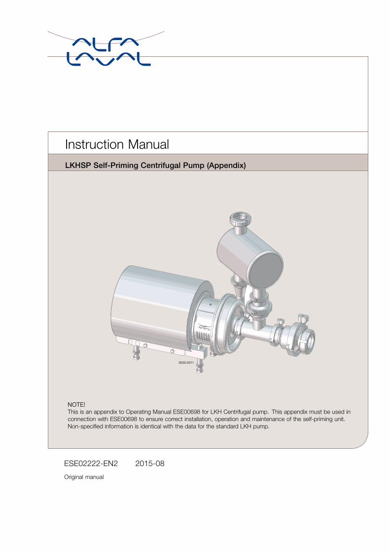
NOTE!This is an appendix to Operating Manual ESE00698 for LKH Centrifugal pump. This appendix must be used inconnection with ESE00698 to ensure correct installation, operation and maintenance of the self-priming unit.Non-specified information is identical with the data for the standard LKH pump.
ESE02222-EN2 2015-08
Original manual
Instruction Manual
LKHSP Self-Priming Centrifugal Pump (Appendix)

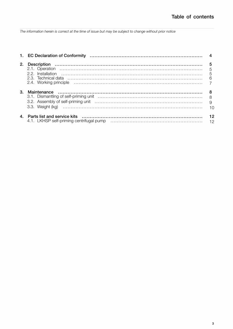
Table of contents
The information herein is correct at the time of issue but may be subject to change without prior notice
1. EC Declaration of Conformity .. . . . . . . . . . . . . . . . . . . . . . . . . . . . . . . . . . . . . . . . . . . . . . . . . . . . . . . . . . . . . . . . . . . . . . 4
2. Description .. . . . . . . . . . . . . . . . . . . . . . . . . . . . . . . . . . . . . . . . . . . . . . . . . . . . . . . . . . . . . . . . . . . . . . . . . . . . . . . . . . . . . . . . . . . . 52.1. Operation .. .. . . . . . . . . . . . . . . . . . . . . . . . . . . . . . . . . . . . . . . . . . . . . . . . . . . . . . . . . . . . . . . . . . . . . . . . . . . . . . . . . . . . . . . 52.2. Installation ... . . . . . . . . . . . . . . . . . . . . . . . . . . . . . . . . . . . . . . . . . . . . . . . . . . . . . . . . . . . . . . . . . . . . . . . . . . . . . . . . . . . . . . 52.3. Technical data .. .. . . . . . . . . . . . . . . . . . . . . . . . . . . . . . . . . . . . . . . . . . . . . . . . . . . . . . . . . . . . . . . . . . . . . . . . . . . . . . . . . . 62.4. Working principle . . . . . . . . . . . . . . . . . . . . . . . . . . . . . . . . . . . . . . . . . . . . . . . . . . . . . . . . . . . . . . . . . . . . . . . . . . . . . . . . . 7
3. Maintenance .. . .. . . . . . . . . . . . . . . . . . . . . . . . . . . . . . . . . . . . . . . . . . . . . . . . . . . . . . . . . . . . . . . . . . . . . . . . . . . . . . . . . . . . . . . 83.1. Dismantling of self-priming unit . . . . . . . . . . . . . . . . . . . . . . . . . . . . . . . . . . . . . . . . . . . . . . . . . . . . . . . . . . . . . . . . . . 83.2. Assembly of self-priming unit . .. . . . . . . . . . . . . . . . . . . . . . . . . . . . . . . . . . . . . . . . . . . . . . . . . . . . . . . . . . . . . . . . . . 93.3. Weight (kg) .. . . . . . . . . . . . . . . . . . . . . . . . . . . . . . . . . . . . . . . . . . . . . . . . . . . . . . . . . . . . . . . . . . . . . . . . . . . . . . . . . . . . . . . 10
4. Parts list and service kits . . . . . . . . . . . . . . . . . . . . . . . . . . . . . . . . . . . . . . . . . . . . . . . . . . . . . . . . . . . . . . . . . . . . . . . . . . . . 124.1. LKHSP self-priming centrifugal pump .... . . . . . . . . . . . . . . . . . . . . . . . . . . . . . . . . . . . . . . . . . . . . . . . . . . . . . . 12
3
1 EC Declaration of Conformity
Revision of Declaration of Conformity 2009-12-29
The Designated Company
Alfa Laval Kolding A/S
Company Name
Albuen 31, DK-6000 Kolding, DenmarkAddress
+45 79 32 22 00Phone No.
hereby declare that
PumpDesignation
LKHSP-10, LKHSP-20, LKHSP-25, LKHSP-35, LKHSP-40
Type
From serial number 10.000 to 1.000.000
is in conformity with the following directive with amendments:- Machinery Directive 2006/42/EC
The person authorised to compile the technical file is the signer of this document
QHSE Manager, Quality, Health andsafety & Environment Annie Dahl
Title Name
Kolding 2013-12-03Place Date Signature
4
2 Description
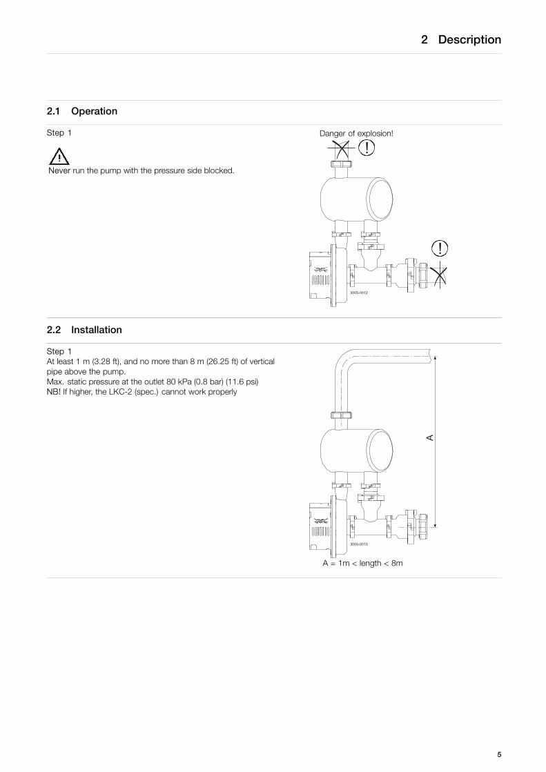
2.1 Operation
Step 1
Never run the pump with the pressure side blocked.
Danger of explosion!
3005-0012
!
!
2.2 Installation
Step 1At least 1 m (3.28 ft), and no more than 8 m (26.25 ft) of verticalpipe above the pump.Max. static pressure at the outlet 80 kPa (0.8 bar) (11.6 psi)NB! If higher, the LKC-2 (spec.) cannot work properly
3005-0013
A
A = 1m < length < 8m
5
2 Description
2.3 Technical data
Pump data
Max. inlet pressure: 1000 kPa (10 bar) (145 psi)Temperature range: -10oC to +100oC (14oF -284oF)Noise level (at 1 m) (3.28 ft): 60 - 80 dB (A)Max. static pressure at the outlet 80 kPa (0.8 bar) (11.6 psi)NB! If higher, the LKC-2 (spec.) cannot work properlyMax. speed 4000 rpm
Flushed seal
Water pressure: Normally atmospheric (max. 1 bar) (14.5 psi)Water consumption: 0.25 -0.5 l/min (0.07-0.13 gpm)
Double mechanical seal
Water pressure: max. 5 bar (72.5 psi)Water consumption: 0.25 -0.5 l/min (0.07-0.13 gpm)
6
2 Description
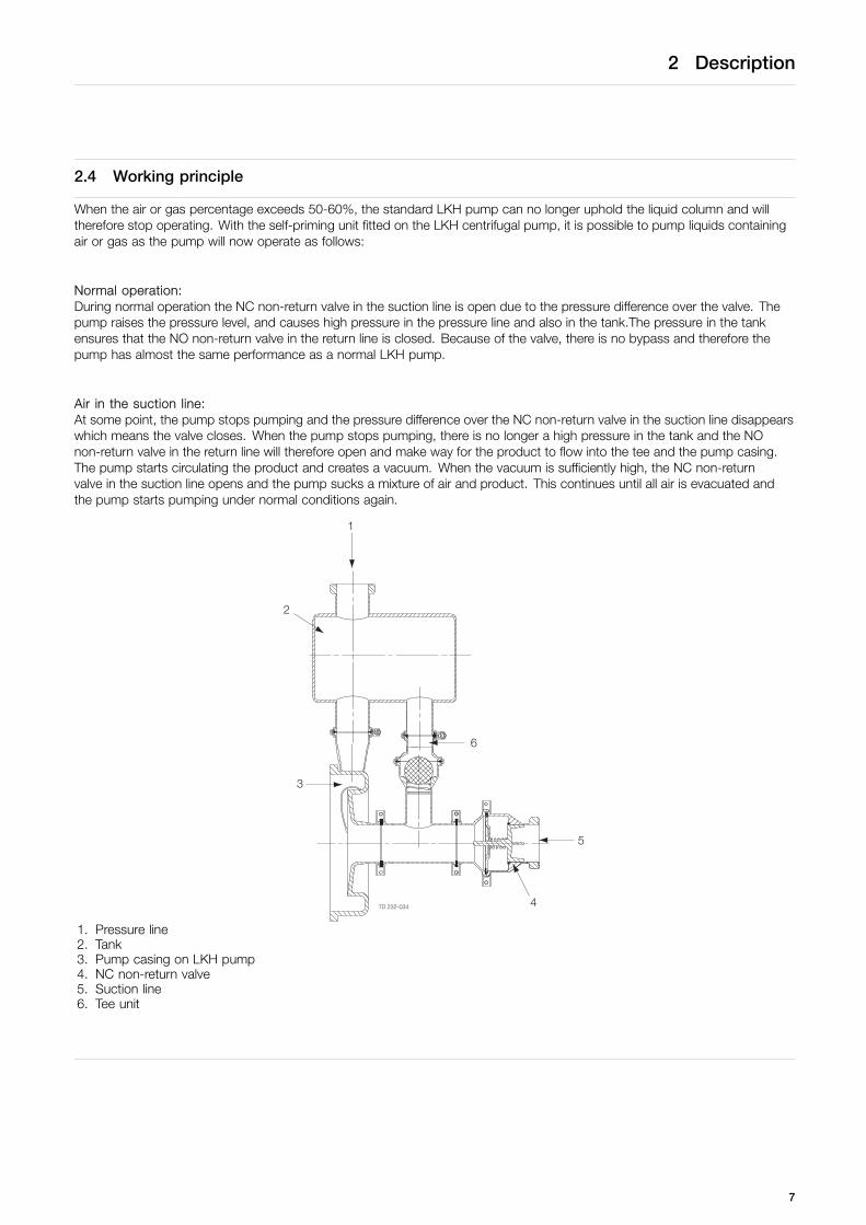
2.4 Working principle
When the air or gas percentage exceeds 50-60%, the standard LKH pump can no longer uphold the liquid column and willtherefore stop operating. With the self-priming unit fitted on the LKH centrifugal pump, it is possible to pump liquids containingair or gas as the pump will now operate as follows:
Normal operation:During normal operation the NC non-return valve in the suction line is open due to the pressure difference over the valve. Thepump raises the pressure level, and causes high pressure in the pressure line and also in the tank.The pressure in the tankensures that the NO non-return valve in the return line is closed. Because of the valve, there is no bypass and therefore thepump has almost the same performance as a normal LKH pump.
Air in the suction line:At some point, the pump stops pumping and the pressure difference over the NC non-return valve in the suction line disappearswhich means the valve closes. When the pump stops pumping, there is no longer a high pressure in the tank and the NOnon-return valve in the return line will therefore open and make way for the product to flow into the tee and the pump casing.The pump starts circulating the product and creates a vacuum. When the vacuum is sufficiently high, the NC non-returnvalve in the suction line opens and the pump sucks a mixture of air and product. This continues until all air is evacuated andthe pump starts pumping under normal conditions again.
1. Pressure line2. Tank3. Pump casing on LKH pump4. NC non-return valve5. Suction line6. Tee unit
7

3 Maintenance
Study the instructions carefully.The items refer to the parts lists and service kits section.Handle scrap correctly.
3.1 Dismantling of self-priming unit
Step 1NOTE!The self-priming unit consists of the following main parts:- Tank- NC non-return valve- Tee with NO non-return valve is mounted on the pump casing
on a standard LKH centrifugal pump, sizes -10, -20, -25, -35,-40. The dismantling instructions for the LKH pump can beseen in instruction manual ESE00698.
1. Pump casing onLKH-pump
2. Tank3. Tee unit4. NC non-return valve
Step 21. Unscrew clamp rings (73, 86) connecting tank (71) to the pump
outlet and tee with NO non-return valve2. Remove the tank.3. Remove seal rings (72, 85).
Step 31. Unscrew clamp ring (74) connecting the NC non-return valve
and tee with NO non-return valve. 2. 3.2. Remove the NC non-return valve.3. Remove seal ring (75).
Step 41. Loosen and remove clamp ring (84).2. Separate valve body (83), liner (77), valve cone (81), guide plate
(79), seal ring (78), O-ring (82) and spring (80) as shown above.
Step 51. Unscrew clamp ring (74) connecting the tee with NO non-return
valve and pump inlet.2. Remove the tee unit.3. Remove seal ring (75).
8
3 Maintenance
Study the instructions carefully.The items refer to the parts lists and service kits section.Handle scrap correctly.
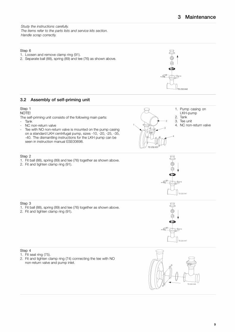
Step 61. Loosen and remove clamp ring (91).2. Separate ball (88), spring (89) and tee (76) as shown above.
3.2 Assembly of self-priming unit
Step 1NOTE!The self-priming unit consists of the following main parts:- Tank- NC non-return valve- Tee with NO non-return valve is mounted on the pump casing
on a standard LKH centrifugal pump, sizes -10, -20, -25, -35,-40. The dismantling instructions for the LKH pump can beseen in instruction manual ESE00698.
1. Pump casing onLKH-pump
2. Tank3. Tee unit4. NC non-return valve
Step 21. Fit ball (88), spring (89) and tee (76) together as shown above.2. Fit and tighten clamp ring (91).
Step 31. Fit ball (88), spring (89) and tee (76) together as shown above.2. Fit and tighten clamp ring (91).
Step 41. Fit seal ring (75).2. Fit and tighten clamp ring (74) connecting the tee with NO
non-return valve and pump inlet.
9
3 Maintenance
Study the instructions carefully.The items refer to the parts lists and service kits section.Handle scrap correctly.
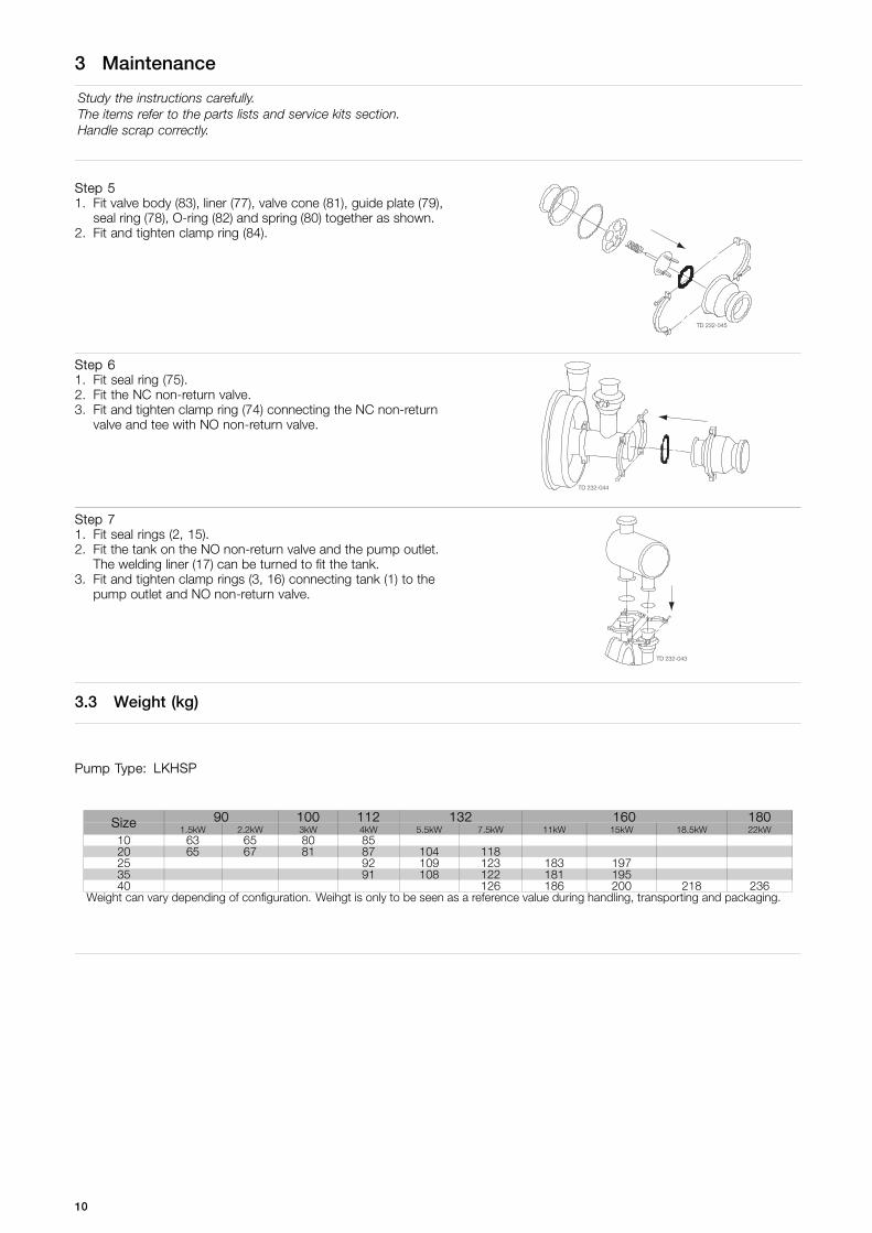
Step 51. Fit valve body (83), liner (77), valve cone (81), guide plate (79),
seal ring (78), O-ring (82) and spring (80) together as shown.2. Fit and tighten clamp ring (84).
Step 61. Fit seal ring (75).2. Fit the NC non-return valve.3. Fit and tighten clamp ring (74) connecting the NC non-return
valve and tee with NO non-return valve.
Step 71. Fit seal rings (2, 15).2. Fit the tank on the NO non-return valve and the pump outlet.
The welding liner (17) can be turned to fit the tank.3. Fit and tighten clamp rings (3, 16) connecting tank (1) to the
pump outlet and NO non-return valve.
3.3 Weight (kg)
Pump Type: LKHSP
90 100 112 132 160 180Size1.5kW 2.2kW 3kW 4kW 5.5kW 7.5kW 11kW 15kW 18.5kW 22kW
10 63 65 80 8520 65 67 81 87 104 11825 92 109 123 183 19735 91 108 122 181 19540 126 186 200 218 236
Weight can vary depending of configuration. Weihgt is only to be seen as a reference value during handling, transporting and packaging.
10

.
11
4 Parts list and service kits
Study the instructions carefully.The items refer to the parts lists and service kits section.Handle scrap correctly.
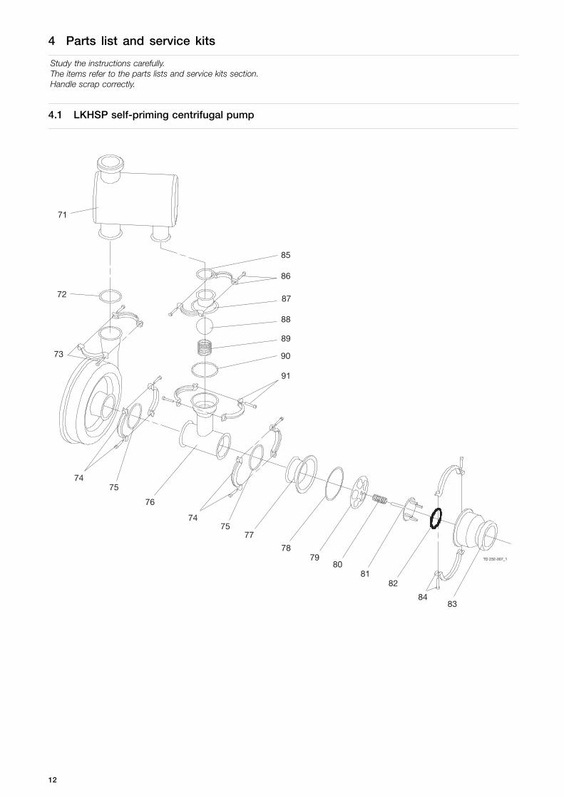
4.1 LKHSP self-priming centrifugal pump
TD 232-007_1
85
86
87
88
89
90
91
71
72
73
7475
76
7475
77
7879
8081
82
8483
12
4 Parts list and service kits
Study the instructions carefully.The items refer to the parts lists and service kits section.Handle scrap correctly.
Parts list
Pos. Qty Denomination
71 1 Tank complete72 1 Seal ring73 1 Clamp ring complete74 2 Clamp ring complete75 2 Seal ring76 1 Tee, ISO-clamp77 1 Liner, ISO-clamp78 1 Seal ring79 1 Guide plate80 1 Spring81 1 Valve cone82 1 O-ring83 1 Valve body84 1 Clamp ring complete85 1 Seal ring86 1 Clamp complete88 1 Ball, PP89 1 Spring90 1 Seal ring91 2 Clamp ring complete
Service kits
DenominationLKHSP -10/-20/, -35
LKHSP -25/- 40
a Service kit, EPDM . . . . . . . . . . . . . . . . . . . . . . . . . . . . . . . . . . . . . . . . . . . . . . 9611922248 9611922251a Service kit, NBR . . . . . . . . . . . . . . . . . . . . . . . . . . . . . . . . . . . . . . . . . . . . . . . 9611922249 9611922252a Service kit, FPM . . . . . . . . . . . . . . . . . . . . . . . . . . . . . . . . . . . . . . . . . . . . . . . . 9611922250 9611922253
Parts marked with are included in the service kits.
Recommended spare parts: service kits.
(900025/3)
13

.
14

.
15

How to contact Alfa LavalContact details for all countries arecontinually updated on our website.Please visit www.alfalaval.com to access the information directly.
© Alfa Laval Corporate ABThis document and its contents is owned by Alfa Laval Corporate AB and protected by laws governing intellectual property and thereto related rights. It is the responsibility of the user of thisdocument to comply with all applicable intellectual property laws. Without limiting any rights related to this document, no part of this document may be copied, reproduced or transmitted in anyform or by any means (electronic, mechanical, photocopying, recording, or otherwise), or for any purpose, without the expressed permission of Alfa Laval Corporate AB. Alfa Laval Corporate ABwill enforce its rights related to this document to the fullest extent of the law, including the seeking of criminal prosecution.