Embed Size (px)
Citation preview
1Replaces same of Rev. R 7/2010
1615.S 3/2013
For file reference, please record the following data:
Model No:
Serial No:
Installation Date:
Installation Location:
When ordering replacement parts for your LMI Metering Pump or Accessory, please include complete Model Number and Serial Number of your unit.
201 Ivyland Road Ivyland, PA 18974
TEL: (215) 293-0401 FAX: (215) 293-0445www.lmipumps.com
CAUTION!Carefully read and understand all precautions
before installing or servicing any metering pump.CAUTION
!
___Instruction Manual Electronic Metering Pumps

2
3
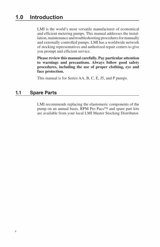
Contents
1.0 Introduction .........................................................................................4 1.1 Spare Parts ..............................................................................4 2.0 Unpacking Check List ........................................................................6 3.0 Pre-Installation Instructions .................................................................8 4.0 Installation ......................................................................................... 10 4.1 Pump Location and Installation ............................................. 10 4.2 Pump Mounting ..................................................................... 10 4.3 Tubing Connections ............................................................... 15 4.4 Multi-Function Valves ............................................................. 16 4.5 4-Function Valve Installation .................................................. 18 4.6 AutoPrime Liquid End ............................................................ 19 4.7 Foot Valve/Suction Tubing Installation ...................................20 4.8 Injection Check Valve and Discharge Tubing Installation .......21 5.0 Liquid End Parts List ........................................................................22 6.0 Start-Up and Adjustment...................................................................23 6.1 Output Adjustment Controls ..................................................23 6.2 Start-Up/Priming for Pump Supplied with Multi-Function Valve ..............................................................24 6.3 Start-Up/Priming without Multi-Function Valve ......................25 6.4 Output Adjustment .................................................................26 6.5 Total Pump Output ................................................................26 7.0 Methods of External Triggering or Pacing B7, C7 and P7 Pumps .................................................................28, 29 8.0 Calibration .........................................................................................30 8.1 Pressure Control ....................................................................31 8.2 Calibration Procedure - On-Site Volumetric Calibration in External Mode ...............................32 9.0 Spare Parts Replacement/Routine Maintenance ..............................32 9.1 Depressurizing the Discharge Line (For Pumps Equipped with a 3-FV or a 4-FV Only) ...............32 9.2 Liquifram™ (Diaphragm) Replacement ..................................33 9.3 Cartridge Valves, Seal Rings/Valve Balls and Injection Check Valve Spring Replacement .........................................3610.0 Checking Pump for Proper Zero Position (Stroke Knob) ...................37 10.1 Type I: Push-on Knob ............................................................3711.0 Troubleshooting.................................................................................4012.0 EPU Resistance Chart ........................................................Back Cover
4
1.0 Introduction
LMI is the world’s most versatile manufacturer of economical and efficient metering pumps. This manual addresses the instal-lation, maintenance and troubleshooting procedures for manually and externally controlled pumps. LMI has a worldwide network of stocking representatives and authorized repair centers to give you prompt and efficient service.
Please review this manual carefully. Pay particular attention to warnings and precautions. Always follow good safety procedures, including the use of proper clothing, eye and face protection.
This manual is for Series AA, B, C, E, J5, and P pumps.
1.1 Spare Parts
LMI recommends replacing the elastomeric components of the pump on an annual basis. RPM Pro Pacs™ and spare part kits are available from your local LMI Master Stocking Distributor.
5
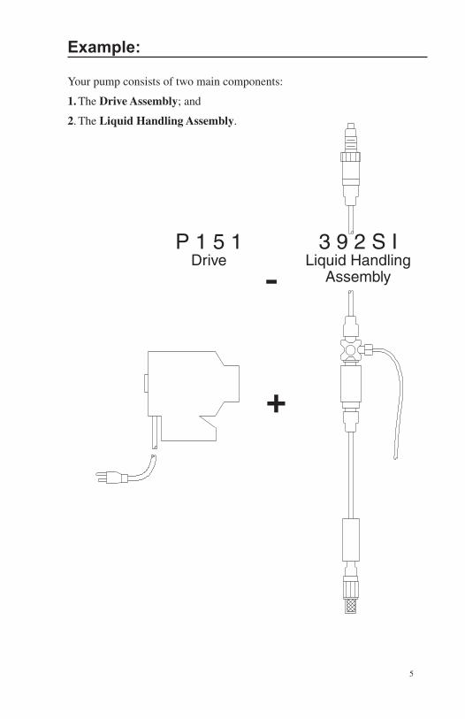
Example:
Your pump consists of two main components:
1. The Drive Assembly; and
2. The Liquid Handling Assembly.
P 1 5 1 Drive
3 9 2 S I Liquid Handling
Assembly-
+
6
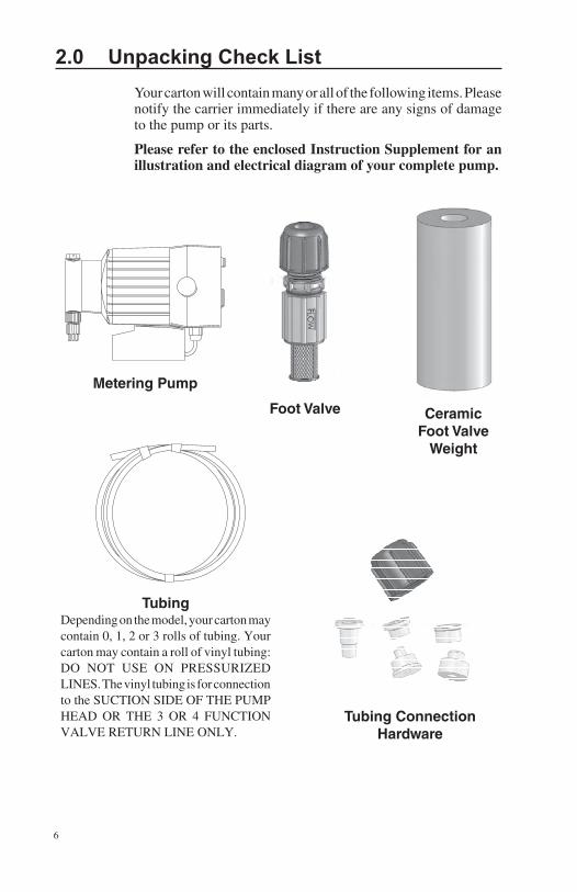
2.0 Unpacking Check List Your carton will contain many or all of the following items. Please notify the carrier immediately if there are any signs of damage to the pump or its parts.
Please refer to the enclosed Instruction Supplement for an illustration and electrical diagram of your complete pump.
TubingDepending on the model, your carton may contain 0, 1, 2 or 3 rolls of tubing. Your carton may contain a roll of vinyl tubing: DO NOT USE ON PRESSURIZED LINES. The vinyl tubing is for connection to the SUCTION SIDE OF THE PUMP HEAD OR THE 3 OR 4 FUNCTION VALVE RETURN LINE ONLY.
Metering Pump
Foot Valve Ceramic Foot Valve
Weight
Tubing Connection Hardware
7
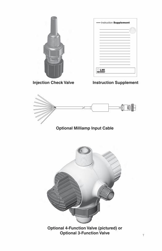
Instruction SupplementInjection Check Valve
Instruction Supplement
LMIMILTONROY
Optional 4-Function Valve (pictured) or Optional 3-Function Valve
Optional Milliamp Input Cable
8
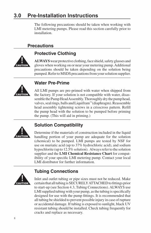
3.0 Pre-Installation Instructions The following precautions should be taken when working with LMI metering pumps. Please read this section carefully prior to installation.
Precautions
Protective Clothing
ALWAYS wear protective clothing, face shield, safety glasses and gloves when working on or near your metering pump. Additional precautions should be taken depending on the solution being pumped. Refer to MSDS precautions from your solution supplier.
Water Pre-Prime
All LMI pumps are pre-primed with water when shipped from the factory. If your solution is not compatible with water, disas-semble the Pump Head Assembly. Thoroughly dry the pump head, valves, seal rings, balls and Liquifram™ (diaphragm). Reassemble head assembly tightening screws in a crisscross pattern. Refill the pump head with the solution to be pumped before priming the pump. (This will aid in priming.)
Solution Compatibility
Determine if the materials of construction included in the liquid handling portion of your pump are adequate for the solution (chemical) to be pumped. LMI pumps are tested by NSF for use on muriatic acid (up to 37% hydrochloric acid), and sodium hypochlorite (up to 12.5% solution). Always refer to the solution supplier and the LMI Chemical Resistance Chart for compat-ibility of your specific LMI metering pump. Contact your local LMI distributor for further information.
Tubing Connections
Inlet and outlet tubing or pipe sizes must not be reduced. Make certain that all tubing is SECURELY ATTACHED to fittings prior to start-up (see Section 4.3, Tubing Connections). ALWAYS use LMI supplied tubing with your pump, as the tubing is specifically designed for use with the pump fittings. It is recommended that all tubing be shielded to prevent possible injury in case of rupture or accidental damage. If tubing is exposed to sunlight, black UV resistant tubing should be installed. Check tubing frequently for cracks and replace as necessary.
CAUTION!
CAUTION!
CAUTION!
CAUTION!
9
Fittings And Machine ThreadsAll fittings should be hand-tightened. An additional 1/8 - 1/4 turn after the fitting contacts the seal ring may be necessary to provide a leak-proof seal. Excessive overtightening or use of a pipe wrench can cause damage to the fittings, seals, or pump head.
All LMI pumps have straight screw machine threads on the head and fittings and are sealed by the seal rings or O-rings. DO NOT use Teflon® tape or pipe dope to seal threads. Teflon® Tape may only be used on the 1/2" NPT thread side of the Injection Check Valve as well as stainless steel liquid end connections.
PlumbingAlways adhere to your local plumbing codes and requirements. Be sure installation does not constitute a cross connection. Check local plumbing codes for guidelines. LMI is not responsible for improper installations.
Back Pressure/Anti-Syphon ValveIf you are pumping downhill or into low or no system pressure, a back pressure/anti-syphon device such as LMI’s Four Function Valve should be installed to prevent overpumping or syphoning. Contact your LMI distributor for furthur information.
Chemical ConcentrationThere is a potential for elevated chemical concentration during periods of no flow, for example, during backwash in the system. Steps, such as turning the pump off, should be taken during operation or installation to prevent this.
See your distributor about other external control options to help mitigate this risk.
Line DepressurizationTo reduce the risk of chemical splash during disassembly or maintenance, all installations should be equipped with line depressurization capability. Using LMI’s Four-Function Valve (4-FV) is one way to include this feature.
Retightening ComponentsPlastic materials will typically exhibit creep characteristics when under pressure over a period of time and to insure a proper fit it may be necessary to retighten the head bolts periodically. To insure proper operation, we recommend tightening the bolts to 25 inch-pounds after the first week of operation and on a monthly basis thereafter.
CAUTION!
CAUTION!
CAUTION!
CAUTION!
CAUTION!
CAUTION!
10
4.0 Installation4.1 Pump Location and Installation
Locate pump in an area convenient to solution tank and electri-cal supply.
The pump should be accessible for routine maintenance, and should not be subjected to ambient temperatures above 122°F (50°C). If the pump will be exposed to direct sunlight, LMI black, UV resistant tubing should be installed.
4.2 Pump Mounting
The pump can be mounted in one of two ways:
A. FLOODED SUCTION (ideal installation); or
B. SUCTION LIFT - when suction lift is less than 5 feet (1.5 m) for solutions having a specific gravity of water. For denser solutions, consult distributor.
Your LMI metering pump must be mounted so that the suction and discharge valves are vertical. NEVER position pump head and fittings horizontally.
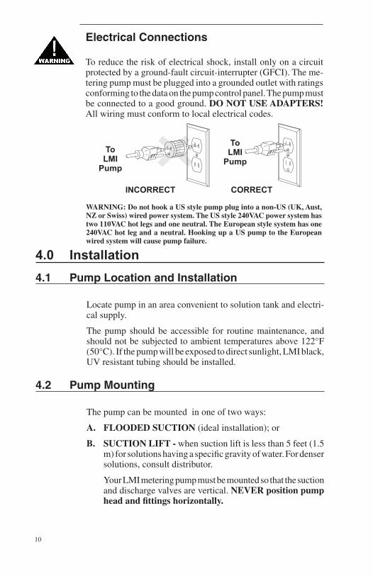
Electrical Connections
To reduce the risk of electrical shock, install only on a circuit protected by a ground-fault circuit-interrupter (GFCI). The me-tering pump must be plugged into a grounded outlet with ratings conforming to the data on the pump control panel. The pump must be connected to a good ground. DO NOT USE ADAPTERS! All wiring must conform to local electrical codes.
WARNING: Do not hook a US style pump plug into a non-US (UK, Aust, NZ or Swiss) wired power system. The US style 240VAC power system has two 110VAC hot legs and one neutral. The European style system has one 240VAC hot leg and a neutral. Hooking up a US pump to the European wired system will cause pump failure.
11
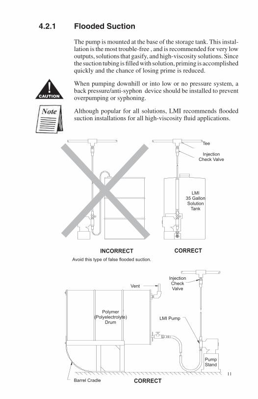
4.2.1 Flooded Suction
The pump is mounted at the base of the storage tank. This instal-lation is the most trouble-free , and is recommended for very low outputs, solutions that gasify, and high-viscosity solutions. Since the suction tubing is filled with solution, priming is accomplished quickly and the chance of losing prime is reduced.
When pumping downhill or into low or no pressure system, a back pressure/anti-syphon device should be installed to prevent overpumping or syphoning.
Although popular for all solutions, LMI recommends flooded suction installations for all high-viscosity fluid applications.
InjectionCheckValve
LMI Pump
PumpStand
Polymer(Polyelectrolyte)
Drum
Vent
CORRECTINCORRECT
LMI35 GallonSolution
Tank
Tee
Avoid this type of false flooded suction.
InjectionCheck Valve
CAUTION!
CORRECTBarrel Cradle
12
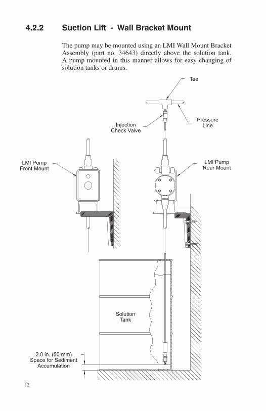
4.2.2 Suction Lift - Wall Bracket Mount
The pump may be mounted using an LMI Wall Mount Bracket Assembly (part no. 34643) directly above the solution tank. A pump mounted in this manner allows for easy changing of solution tanks or drums.
InjectionCheck Valve
PressureLine
2.0 in. (50 mm)Space for Sediment
Accumulation
SolutionTank
LMI PumpFront Mount
LMI PumpRear Mount
Tee
13
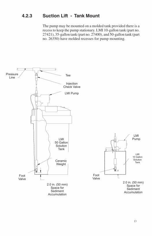
4.2.3 Suction Lift - Tank Mount
The pump may be mounted on a molded tank provided there is a recess to keep the pump stationary. LMI 10-gallon tank (part no. 27421), 35-gallon tank (part no. 27400), and 50-gallon tank (part no. 26350) have molded recesses for pump mounting.
Tee
InjectionCheck Valve
LMI50 GallonSolution
Tank
Foot Valve
2.0 in. (50 mm)Space forSediment
Accumulation
2.0 in. (50 mm)Space forSediment
Accumulation
Foot Valve
LMI Pump
LMI10 GallonSolution
Tank
LMI Pump
PressureLine
CeramicWeight
14
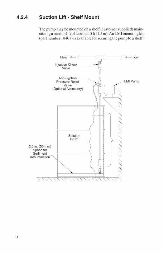
4.2.4 Suction Lift - Shelf Mount
The pump may be mounted on a shelf (customer supplied) main-taining a suction lift of less than 5 ft (1.5 m). An LMI mounting kit (part number 10461) is available for securing the pump to a shelf.
Flow
Injection CheckValve
Anti-SyphonPressure Relief
Valve(Optional Accessory)
LMI Pump
SolutionDrum
2.0 in. (50 mm) Space forSediment
Accumulation
Flow
15
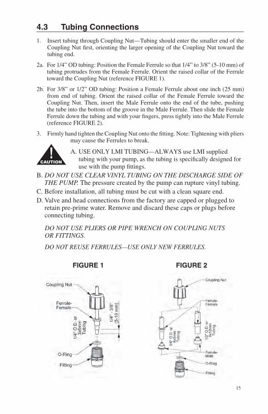
4.3 Tubing Connections
1. Insert tubing through Coupling Nut—Tubing should enter the smaller end of the Coupling Nut first, orienting the larger opening of the Coupling Nut toward the tubing end.
2a. For 1/4” OD tubing: Position the Female Ferrule so that 1/4” to 3/8” (5-10 mm) of tubing protrudes from the Female Ferrule. Orient the raised collar of the Ferrule toward the Coupling Nut (reference FIGURE 1).
2b. For 3/8” or 1/2” OD tubing: Position a Female Ferrule about one inch (25 mm) from end of tubing. Orient the raised collar of the Female Ferrule toward the Coupling Nut. Then, insert the Male Ferrule onto the end of the tube, pushing the tube into the bottom of the groove in the Male Ferrule. Then slide the Female Ferrule down the tubing and with your fingers, press tightly into the Male Ferrule (reference FIGURE 2).
3. Firmly hand tighten the Coupling Nut onto the fitting. Note: Tightening with pliers may cause the Ferrules to break.
A. USE ONLY LMI TUBING—ALWAYS use LMI supplied tubing with your pump, as the tubing is specifically designed for use with the pump fittings.
B. DO NOT USE CLEAR VINYL TUBING ON THE DISCHARGE SIDE OF THE PUMP. The pressure created by the pump can rupture vinyl tubing.
C. Before installation, all tubing must be cut with a clean square end.D. Valve and head connections from the factory are capped or plugged to
retain pre-prime water. Remove and discard these caps or plugs before connecting tubing.
DO NOT USE PLIERS OR PIPE WRENCH ON COUPLING NUTS OR FITTINGS.
DO NOT REUSE FERRULES—USE ONLY NEW FERRULES.
FIGURE 1 FIGURE 2
CAUTION!
16
4.4 Multi-Function Valves
Your pump may be equipped with one of the following multi-function valves: 3-FV, 4-FV, or standard discharge valve. If your pump is not equipped with a multi-function valve and you feel it is needed in your application, it can be purchased as an accessory. Contact your local LMI stocking distributor.
4.4.1 Three Function Valve (3-FV) 1. Pressure Relief
If the discharge line is over pressurized, the valve opens sending solution back to the supply tank.
2. Line Depressurization
Opening the relief knob provides line drain back to the sup-ply tank.
3. Priming Aid
Opening the relief knob assists in priming the pump by venting the discharge line to the atmosphere.
4.4.2 Four Function Valve (4-FV) 1. Pressure Relief
If the discharge line is over pressurized, the valve opens sending solution back to the supply tank.
2. Line Depressurization
Opening the relief knob provides line drain back to the sup-ply tank.
3. Anti-Syphon
Prevents syphoning when pumping solution downhill or into a vacuum.
4. Back Pressure
Supplies approximately 25 psi back pressure to prevent over-pumping when little or no system back pressure is present.
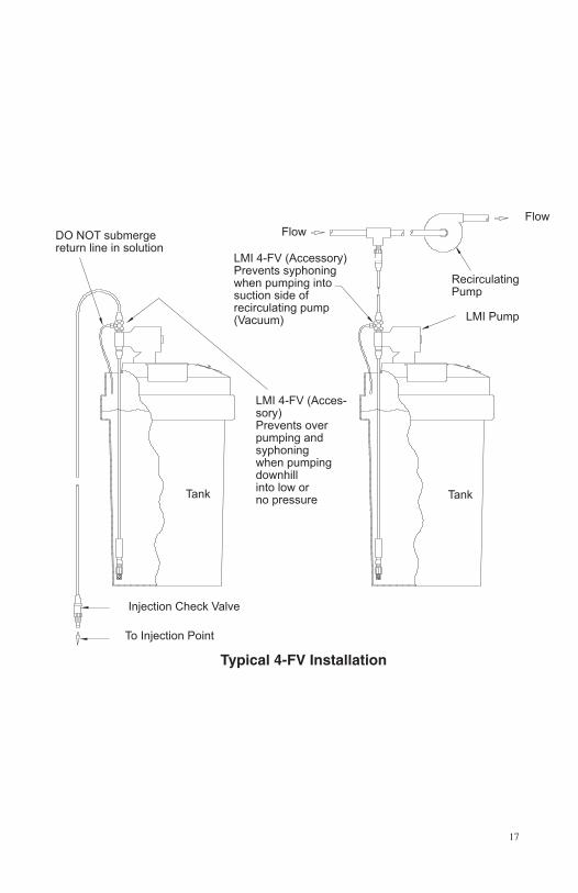
17
Typical 4-FV Installation
FlowFlow
RecirculatingPump
LMI Pump
Tank
LMI 4-FV (Acces-sory)Prevents over pumping and syphoning when pumping downhill into low or no pressure
DO NOT submergereturn line in solution
Injection Check Valve
To Injection Point
LMI 4-FV (Accessory)Prevents syphoningwhen pumping intosuction side ofrecirculating pump(Vacuum)
Tank
18
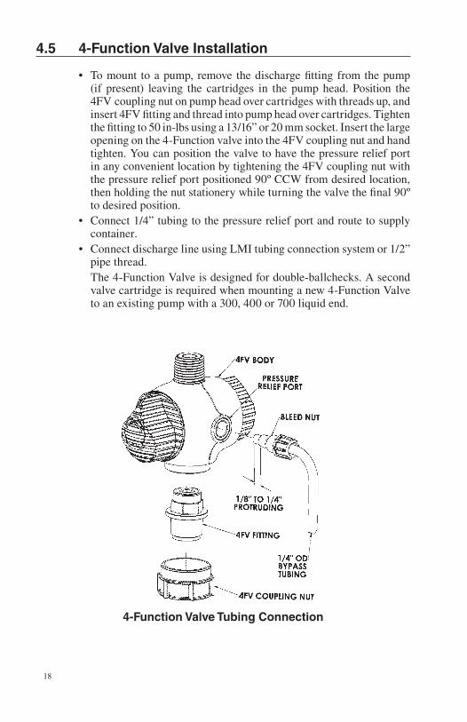
4.5 4-Function Valve Installation
• Tomount toapump,remove thedischargefittingfromthepump(if present) leaving the cartridges in the pump head. Position the 4FV coupling nut on pump head over cartridges with threads up, and insert 4FV fitting and thread into pump head over cartridges. Tighten the fitting to 50 in-lbs using a 13/16” or 20 mm socket. Insert the large opening on the 4-Function valve into the 4FV coupling nut and hand tighten. You can position the valve to have the pressure relief port in any convenient location by tightening the 4FV coupling nut with the pressure relief port positioned 90º CCW from desired location, then holding the nut stationery while turning the valve the final 90º to desired position.
• Connect1/4”tubingtothepressurereliefportandroutetosupplycontainer.
• ConnectdischargelineusingLMItubingconnectionsystemor1/2”pipe thread.
The 4-Function Valve is designed for double-ballchecks. A second valve cartridge is required when mounting a new 4-Function Valve to an existing pump with a 300, 400 or 700 liquid end.
4-Function Valve Tubing Connection
19
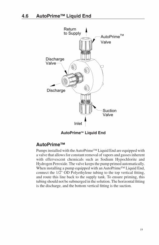
4.6 AutoPrime™ Liquid End
DischargeValve
AutoPrimeTM
Valve
SuctionValve
Return to Supply
Discharge
Inlet
AutoPrime™ Liquid End
AutoPrime™Pumps installed with the AutoPrime™ Liquid End are equipped with a valve that allows for constant removal of vapors and gasses inherent with effervescent chemicals such as Sodium Hypochlorite and Hydrogen Peroxide. The valve keeps the pump primed automatically. When installing a pump equipped with an AutoPrime™ Liquid End, connect the 1/2" OD Polyethylene tubing to the top vertical fitting, and route this line back to the supply tank. To ensure priming, this tubing should not be submerged in the solution. The horizontal fitting is the discharge, and the bottom vertical fitting is the suction.
20
Pump models equipped with high-viscosity liquid ends are not equipped with foot valves. Flooded suction is recommended. A 1/2" NPT connector is included for flooded suction installations.
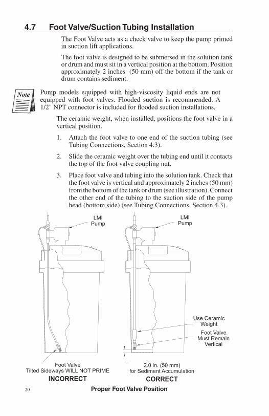
The ceramic weight, when installed, positions the foot valve in a vertical position.
1. Attach the foot valve to one end of the suction tubing (see Tubing Connections, Section 4.3).
2. Slide the ceramic weight over the tubing end until it contacts the top of the foot valve coupling nut.
3. Place foot valve and tubing into the solution tank. Check that the foot valve is vertical and approximately 2 inches (50 mm) from the bottom of the tank or drum (see illustration). Connect the other end of the tubing to the suction side of the pump head (bottom side) (see Tubing Connections, Section 4.3).
Proper Foot Valve Position
LMI Pump
Use CeramicWeightFoot Valve
Must RemainVertical
Foot ValveTilted Sideways WILL NOT PRIME
INCORRECT
2.0 in. (50 mm)for Sediment Accumulation
CORRECT
LMI Pump
4.7 Foot Valve/Suction Tubing InstallationThe Foot Valve acts as a check valve to keep the pump primed in suction lift applications.
The foot valve is designed to be submersed in the solution tank or drum and must sit in a vertical position at the bottom. Position approximately 2 inches (50 mm) off the bottom if the tank or drum contains sediment.
21
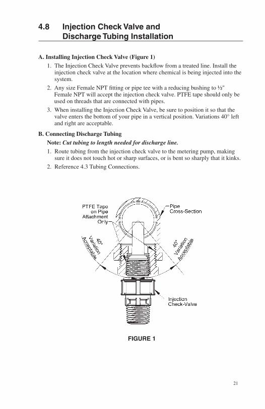
4.8 Injection Check Valve and Discharge Tubing Installation
A. Installing Injection Check Valve (Figure 1)
1. The Injection Check Valve prevents backflow from a treated line. Install the injection check valve at the location where chemical is being injected into the system.
2. Any size Female NPT fitting or pipe tee with a reducing bushing to ½" Female NPT will accept the injection check valve. PTFE tape should only be used on threads that are connected with pipes.
3. When installing the Injection Check Valve, be sure to position it so that the valve enters the bottom of your pipe in a vertical position. Variations 40° left and right are acceptable.
B. Connecting Discharge Tubing
Note: Cut tubing to length needed for discharge line.
1. Route tubing from the injection check valve to the metering pump, making sure it does not touch hot or sharp surfaces, or is bent so sharply that it kinks.
2. Reference 4.3 Tubing Connections.
FIGURE 1
22
5.0 Liquid End Parts ListReference Liquid End Sheets on LMI Online Library at: www.lmipumps.com.
1. Select “Online Literature Library” in the Navigation Bar on left.
2. Once on Online Literature Library use “Product” drop down to select “Liquid Handling Assemblies.”
3. Select “Gallery” or ”Index” to view Liquid End sheets.
23
6.0 Start-up and Adjustmenta.) The pump is normally self-priming if suction lift is 5 ft (1.5m) or less and the steps below are followed.
b.) Pumps are shipped from the factory with water in the pump head to aid in priming.
6.1 Output Adjustment Controls
Manual series pump controls are not equipped with pressure control.
1. Pressure Control Adjustment (if equipped): Pressure control provides the adjustment of the pump’s pressure capability and power consumption, reducing heat, pipe shock and pulsation while increasing pump life. See Section 7.0 after priming for proper adjustment settings.
2. Speed Adjustment (Upper Knob) (if equipped): Speed control provides adjustment of the percent of maximum strokes per minute. Turning this knob clockwise increases stroke frequency (speed).
3. Stroke Adjustment (Lower Knob): Stroke control provides adjustment of the percent maximum of solution discharged during each pump actuation. Turning this knob clockwise
increases solution displacement.
AA7 and P7 Only: When operating the pump in external mode, the speed control knob should be turned fully counter-clockwise .
24
CAUTION!
6.2 Start-Up/Priming for Pump Supplied with Multi-Function Valve
Read this entire section completely before proceeding.
When all precautionary steps have been taken, the pump is mounted, and the tubing is securely attached, you may now start priming the pump.
1. Plug in or switch the pump on.
2. While the pump is running, set the speed knob at 80% and the stroke knob at 100%.
If the pump is equipped with pressure control, turn fully clock-wise.
3. 1/4 turn open the relief side (black knob) of the multi-func-tion valve.
4. The suction tubing should begin to fill with solution from the tank.
5. A small amount of solution will begin to discharge out the return line of the multi-function valve. Once this happens, 1/4 turn or release the knob and SHUT THE PUMP OFF. (If pump is not equipped with an on/off switch, disconnect the power cord.)
6. The pump is now primed.
7. Proceed to output adjustment, Section 6.4.
If the pump does not self-prime, remove the multi-function valve on the discharge side of the pump head. Remove the check valve and pour water or solution into the port until the head is filled. Replace valve, then follow start up/priming steps.
25
6.3 Start-Up/Priming without Multi-Function Valve
Read this entire section completely before proceeding.
When all precautionary steps have been taken, the pump is mounted, and the tubing is securely attached, you may now prime the pump.
1. Plug in or switch on the pump.
2. While the pump is running, set the speed knob at 80% and the stroke knob at 100%.
If the pump is equipped with pressure control, turn fully clockwise .
3. The suction tubing should begin to fill with solution from the tank.
4. Once the solution begins to exit the pump head on the discharge side, SHUT THE PUMP OFF. (If pump is not equipped with an on/off switch, disconnect the power cord).
5. The pump is now primed.
6. Proceed to output adjustment, Section 6.4.
If the pump does not self-prime, remove the fitting on the dis-charge side of the pump head. Remove the ball and pour water or solution into the port until the head is filled. Replace valve, then follow start up/priming steps.
Start-Up/Priming for AutoPrime™ Heads Read this entire section completely before proceeding. When all precautionary steps have been taken, the pump is
mounted, and the tubing is securely attached, you may prime the pump.
1. Plug in or switch on the pump.
2. While the pump is running, set the speed knob and the stroke knob at 100%.
3. The suction tubing should begin to fill with solution from the tank as the AutoPrime™ valve purges air from the pump head.
4. Once the solution begins to exit the pump head through both the discharge valve and the AutoPrime™ valve, SHUT THE PUMP OFF.
5. The pump is now primed.
6. Proceed to output adjustment, Section 6.4.
CAUTION!
26
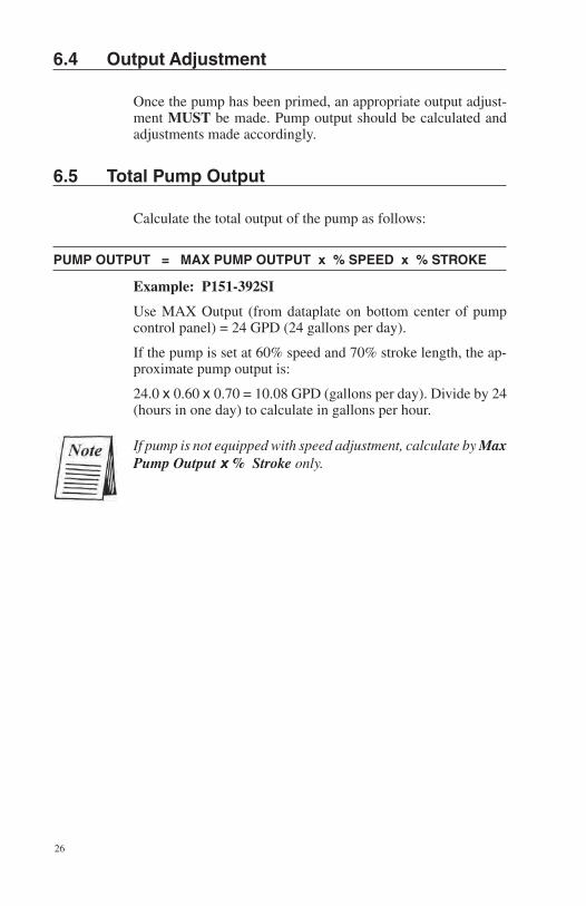
6.4 Output Adjustment
Once the pump has been primed, an appropriate output adjust-ment MUST be made. Pump output should be calculated and adjustments made accordingly.
6.5 Total Pump Output
Calculate the total output of the pump as follows:
PUMP OUTPUT = MAX PUMP OUTPUT x % SPEED x % STROKE
Example: P151-392SI
Use MAX Output (from dataplate on bottom center of pump control panel) = 24 GPD (24 gallons per day).
If the pump is set at 60% speed and 70% stroke length, the ap-proximate pump output is:
24.0 x 0.60 x 0.70 = 10.08 GPD (gallons per day). Divide by 24 (hours in one day) to calculate in gallons per hour.
If pump is not equipped with speed adjustment, calculate by Max Pump Output x % Stroke only.

27
28
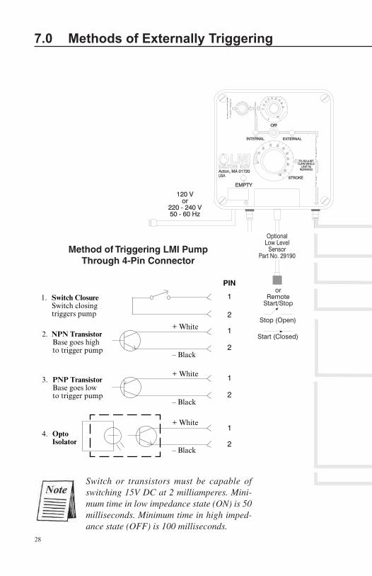
Switch or transistors must be capable of switching 15V DC at 2 milliamperes. Mini-mum time in low impedance state (ON) is 50 milliseconds. Minimum time in high imped-ance state (OFF) is 100 milliseconds.
4. Opto Isolator
2. NPN Transistor Base goes high to trigger pump
– Black
– Black
+ White
+ White
3. PNP Transistor Base goes low to trigger pump
+ White
– Black
1. Switch Closure Switch closing triggers pump
Method of Triggering LMI PumpThrough 4-Pin Connector
7.0 Methods of Externally Triggering or Pacing B7, C7 and P7 Pumps
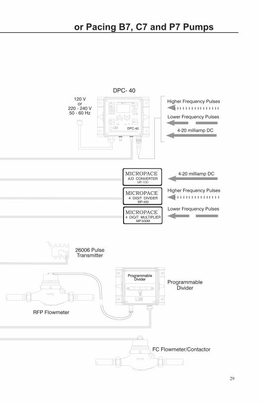
29
7.0 Methods of Externally Triggering or Pacing B7, C7 and P7 Pumps
30
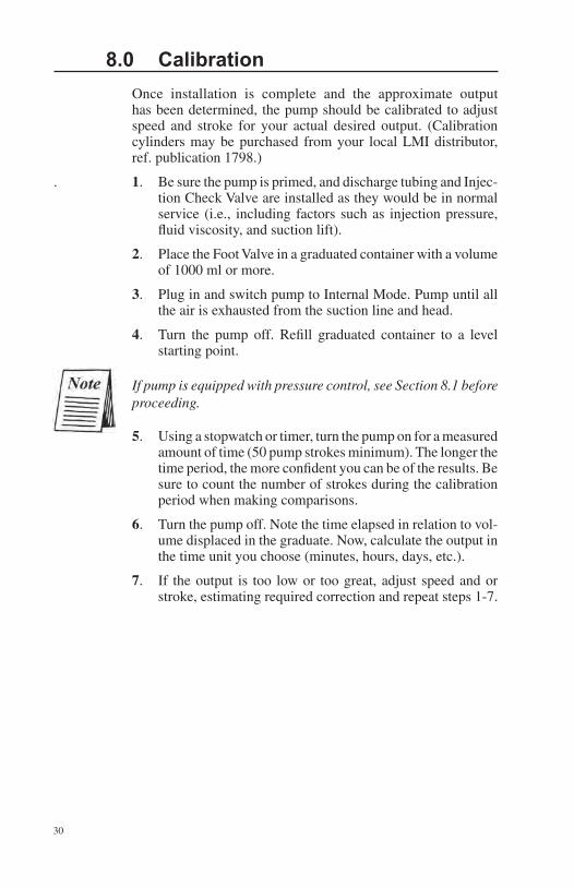
8.0 Calibration Once installation is complete and the approximate output has been determined, the pump should be calibrated to adjust speed and stroke for your actual desired output. (Calibration cylinders may be purchased from your local LMI distributor, ref. publication 1798.)
. 1. Be sure the pump is primed, and discharge tubing and Injec-tion Check Valve are installed as they would be in normal service (i.e., including factors such as injection pressure, fluid viscosity, and suction lift).
2. Place the Foot Valve in a graduated container with a volume of 1000 ml or more.
3. Plug in and switch pump to Internal Mode. Pump until all the air is exhausted from the suction line and head.
4. Turn the pump off. Refill graduated container to a level starting point.
If pump is equipped with pressure control, see Section 8.1 before proceeding.
5. Using a stopwatch or timer, turn the pump on for a measured amount of time (50 pump strokes minimum). The longer the time period, the more confident you can be of the results. Be sure to count the number of strokes during the calibration period when making comparisons.
6. Turn the pump off. Note the time elapsed in relation to vol-ume displaced in the graduate. Now, calculate the output in the time unit you choose (minutes, hours, days, etc.).
7. If the output is too low or too great, adjust speed and or stroke, estimating required correction and repeat steps 1-7.
31
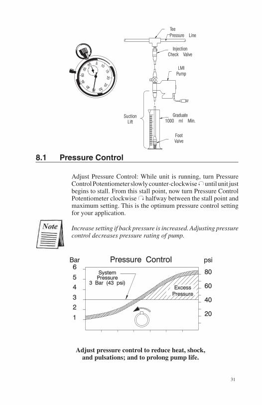
8.1 Pressure Control
Adjust Pressure Control: While unit is running, turn Pressure Control Potentiometer slowly counter-clockwise until unit just begins to stall. From this stall point, now turn Pressure Control Potentiometer clockwise halfway between the stall point and maximum setting. This is the optimum pressure control setting for your application.
Increase setting if back pressure is increased. Adjusting pressure control decreases pressure rating of pump.
Adjust pressure control to reduce heat, shock, and pulsations; and to prolong pump life.
32
CAUTION!
8.2 Calibration Procedure - On-Site Volumetric Calibration in External Mode
1. Since pump output is governed by an external device such as Flowmeter-Pulser, Liquitron™ Controller, or 4-20 mA DC signal from an instrument with an LMI Analog-to-Digital Converter, only the output per stroke may be calibrated.
2. With pump primed and discharge tubing connected to the injection point as it would be in normal service, place Foot Valve Assembly in a graduated container with a volume of 1000 ml or more.
3. Switch pump to Internal mode with Speed Knob set at 100 until air is exhausted from suction line and pump head.
4. Adjust Pressure Control (if desired) - See Section 8.1.
5. Switch pump OFF and note solution level in graduated container. Refill graduate to a starting point.
6. Switch pump ON and count the number of strokes for exactly one minute, then switch pump OFF.
7. Note volume pumped during the calibration period of one minute. Divide into this the number of strokes to determine the volume of solution pumped per stroke.
Example: 500 ml in 100 strokes = 5.0 ml per stroke.
Multiply this by your expected stroke rate per minute, per hour or per day and compare with desired output requirements.
8. Adjust Stroke Length Knob (lower knob) to your best estimate of required correction and repeat calibration procedure.
9.0 Spare Parts Replacement Routine Maintenance 9.1 Depressurizing the Discharge Line (For Pumps Equipped with a 3-FV or a 4-FV only)
ALWAYS wear protective clothing, face shield, safety glasses and gloves when performing any maintenance or replacement on your pump.
33
Read steps 1 and 2 below before proceeding.
1. Be sure the Injection Check Valve is properly installed and is operating. If a shut off valve has been installed downstream of the Injection Valve, it should be closed.
Be sure your relief tubing is connected to your multi-function valve and runs back to your solution drum or tank.
2. 1/4 turn the black knob on the valve. The discharge line is now depressurized. Keep valve open until solution drains back down the discharge tubing into solution drum or tank. Then 1/4 turn knob to normal position.
9.2 Liquifram™ (Diaphragm) Replacement
ALWAYS wear protective clothing, face shield, safety glasses and gloves when working near or performing any maintenance or replacement on your pump. See MSDS information from solution supplier for additional precautions.
LMI metering pumps are designed for trouble-free operation, yet routine maintenance of elastomeric parts is essential for optimum performance. This involves replacing the Liquifram™, cartridge valves or seal rings/valve balls, multi-function valve cap assemblies and the injection check valve spring. LMI recommends replacing these parts at least once a year; however, frequency will depend on your particular application.
When replacing the Liquifram™ and the cartridge valves or seal rings/valve balls, the injection check valve spring should also be replaced (see next Section 9.3). A Spare Parts Kit (SP-#) or RPM Pro Pac™ kit containing these parts may be obtained from your local distributor.
Replacing the Liquifram™:
1. Carefully depressurize, drain, and disconnect the discharge line (see Section 8.1 in this manual). Place the Foot Valve into a container of water or other neutralizing solution. Turn the pump on to flush the head assembly. Once the pump head has been flushed, lift the Foot Valve out of the solution and continue to pump air into the pump head until the pump head is purged of water or neutralizing solution.
CAUTION!
CAUTION!
CAUTION!
34
CAUTION!
If the liquid cannot be pumped due to Liquifram™ rupture using protective clothing, gloves and face shield, carefully disconnect the suction and discharge tubing. Remove the four screws to the head and immerse the head in water or other neutralizing solution.
2. Start the pump. While running, set the stroke knob to zero and turn the pump off.
See Section 10.0 for proper zero.
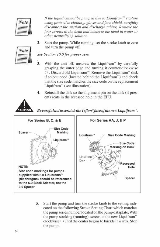
3. With the unit off, unscrew the Liquifram™ by carefully grasping the outer edge and turning it counter-clockwise
. Discard old Liquifram™. Remove the Liquifram™ disk if so equipped (located behind the Liquifram™) and check that the size code matches the size code on the replacement Liquifram™ (see illustration).
4. Reinstall the disk so the alignment pin on the disk (if pres-ent) seats in the recessed hole in the EPU.
Be careful not to scratch the Teflon® face of the new Liquifram™.
5. Start the pump and turn the stroke knob to the setting indi-cated on the following Stroke Setting Chart which matches the pump series number located on the pump dataplate. With the pump stroking (running), screw on the new Liquifram™
clockwise until the center begins to buckle inwards. Stop the pump.
For Series AA, J, & PFor Series B, C, & E
35
Liquifram™ Stroke Setting Chart
Pump Series Stroke Knob Setting
All AA, B, J, P Series C10, C11, C12, C70, C71, C72, C76, 90% C90, C91, C92, E70, E71, E72
C78 50%
C13, C14, C73, C74, C77, C93, C94, E73, E74 70%
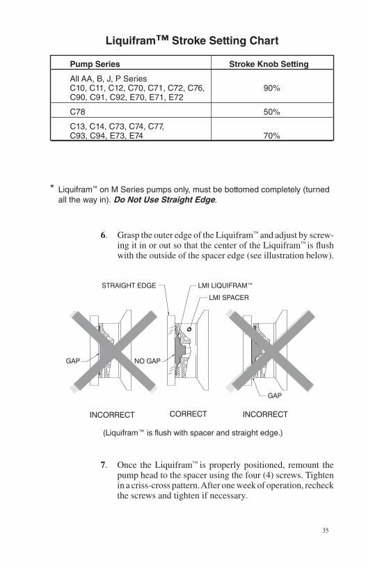
* Liquifram™ on M Series pumps only, must be bottomed completely (turned all the way in). Do Not Use Straight Edge.
6. Grasp the outer edge of the Liquifram™ and adjust by screw-ing it in or out so that the center of the Liquifram™ is flush with the outside of the spacer edge (see illustration below).
7. Once the Liquifram™ is properly positioned, remount the pump head to the spacer using the four (4) screws. Tighten in a criss-cross pattern. After one week of operation, recheck the screws and tighten if necessary.
36
CAUTION!
9.3 Cartridge Valves, Seal Rings/Valve Balls and Injection Check Valve Spring Replacement
ALWAYS wear protective clothing, face shield, safety glasses and gloves when working on or performing any maintenance or replacement on your pump. See MSDS information from solution supplier for additional precautions.
1. Refer to the LMI Metering Pump Price List for the proper Spare Parts Kit or RPM Pro Pac™ kit number or contact your local LMI stocking distributor.
2. Carefully depressurize and disconnect the discharge line (see Section 9.1 in this manual). Place the Foot Valve into a container of water or other neutralizing solution. Turn the pump on to flush the head assembly. Once the pump has been flushed, lift the Foot Valve out and continue to pump to let air into the pump head until pump is purged of water or neutralizing solution.
Once the pump has been flushed, lift the Foot Valve out and continue to let air into the pump head until pump is purged of water or neutralizing solution.
If the liquid cannot be pumped due to Liquifram™ rupture, with protective clothing, gloves and face shield, carefully disconnect the tubing and four screws to remove the head. Immerse the head in water or other neutralizing solution.
Spare part replacement kits include specific instructions for valve replacement. Please follow the instructions included with the replacement kit.
IMPORTANT: Before disassembling the check valves, note the orientation of the valve.
3. Carefully disconnect one tubing connection and fitting at a time, then remove and replace the worn valve.
If necessary, carefully loosen stuck valves by prying side to side using a small screwdriver through the center hole of the valve.
4. Install new check valves in each location.
CAUTION!
37
IMPORTANT: Note correct orientation of each check valve.
5. Install the new spring in the Injection Check Valve.
Depressurize and drain pipeline (or isolate I.C.V. point using valves) so that I.C.V. can safely be disassembled.
10.0 Checking Pump for Proper Zero Position (Stroke Knob)
1. With pump running, turn stroke knob counter-clockwise toward zero or end of black or red band on dial.
2. LISTEN to the clicking as the pump is running. The pump should operate quietly at the zero position (no clicking).
3. If the pump continues to click at zero or stops clicking before zero is reached, the pump zero must be reset (see Section 10.1 or 10.2).
10.1 Type I - Push on Knob Re-Zeroing and Stroke Knob Disassembly and Assembly
` 1. Remove stroke knob from the pump by grasping the knob firmly and pulling it toward you.
2. Pry off the yellow cap.
3. Place the knob on a flat surface.
4. Using needle-nose pliers, squeeze the inner section together while lifting the outer section up.
5. Push the inner section back onto the “D” shaped stroke shaft.
6. With the pump running, zero the pump by turning the inner section of the knob counter-clockwise until the pump stops clicking.
CAUTION!
38
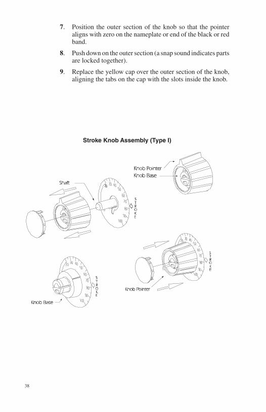
7. Position the outer section of the knob so that the pointer aligns with zero on the nameplate or end of the black or red band.
8. Push down on the outer section (a snap sound indicates parts are locked together).
9. Replace the yellow cap over the outer section of the knob, aligning the tabs on the cap with the slots inside the knob.
Stroke Knob Assembly (Type I)

39
40
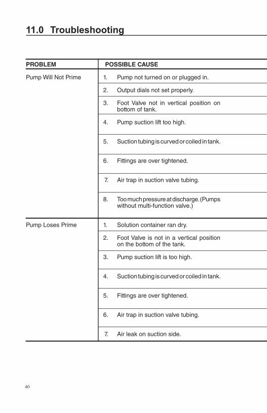
PROBLEM POSSIBLE CAUSE
Pump Will Not Prime 1. Pump not turned on or plugged in.
2. Output dials not set properly.
3. Foot Valve not in vertical position on bottom of tank.
4. Pump suction lift too high.
5. Suction tubing is curved or coiled in tank.
6. Fittings are over tightened.
7. Air trap in suction valve tubing.
8. Too much pressure at discharge. (Pumps without multi-function valve.)
Pump Loses Prime 1. Solution container ran dry.
2. Foot Valve is not in a vertical position on the bottom of the tank.
3. Pump suction lift is too high.
4. Suction tubing is curved or coiled in tank.
5. Fittings are over tightened.
6. Air trap in suction valve tubing.
7. Air leak on suction side.
11.0 Troubleshooting
41
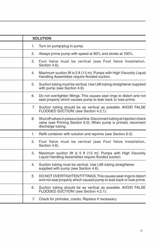
SOLUTION
1. Turn on pump/plug in pump.
2. Always prime pump with speed at 80% and stroke at 100%.
3. Foot Valve must be vertical (see Foot Valve Installation, Section 4.6).
4. Maximum suction lift is 5 ft (1.5 m). Pumps with High Viscosity Liquid Handling Assemblies require flooded suction.
5. Suction tubing must be vertical. Use LMI tubing straightener supplied with pump (see Section 4.6).
6. Do not overtighten fittings. This causes seal rings to distort and not seat properly which causes pump to leak back or lose prime.
7. Suction tubing should be as vertical as possible. AVOID FALSE FLOODED SUCTION! (see Section 4.2.1).
8. Shut off valves in pressurized line. Disconnect tubing at injection check valve (see Priming Section 6.0). When pump is primed, reconnect discharge tubing.
1. Refill container with solution and reprime (see Section 6.0).
2. Foot Valve must be vertical (see Foot Valve Installation, Section 4.6).
3. Maximum suction lift is 5 ft (1.5 m). Pumps with High Viscosity Liquid Handling Assemblies require flooded suction.
4. Suction tubing must be vertical. Use LMI tubing straightener supplied with pump (see Section 4.6).
5. DO NOT OVERTIgHTEN FITTINgS. This causes seal rings to distort and not seat properly which caused pump to leak back or lose prime.
6. Suction tubing should be as vertical as possible. AVOID FALSE FLOODED SUCTION! (see Section 4.2.1).
7. Check for pinholes, cracks. Replace if necessary.
11.0 Troubleshooting
42
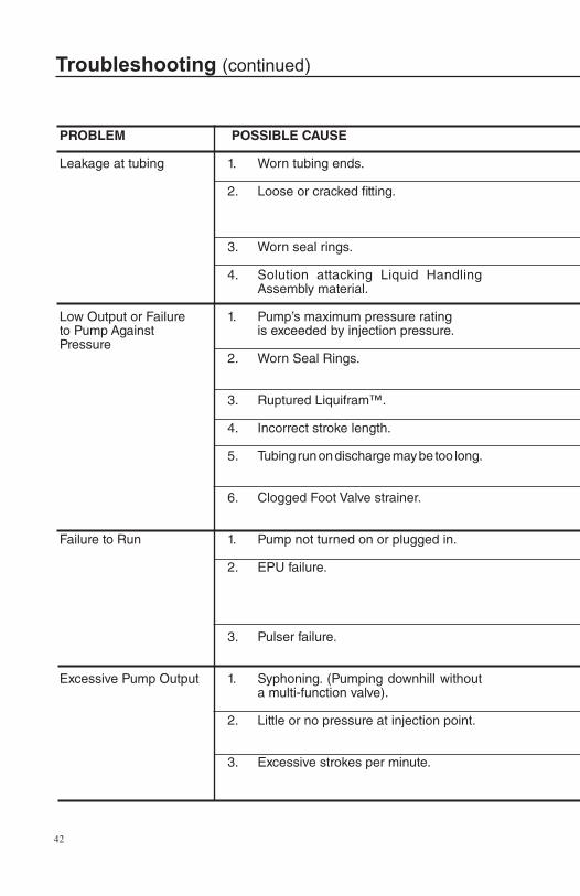
PROBLEM POSSIBLE CAUSE
Leakage at tubing 1. Worn tubing ends.
2. Loose or cracked fitting.
3. Worn seal rings.
4. Solution attacking Liquid Handling Assembly material.
Low Output or Failure 1. Pump’s maximum pressure ratingto Pump Against is exceeded by injection pressure.Pressure 2. Worn Seal Rings.
3. Ruptured Liquifram™.
4. Incorrect stroke length.
5. Tubing run on discharge may be too long.
6. Clogged Foot Valve strainer.
Failure to Run 1. Pump not turned on or plugged in.
2. EPU failure.
3. Pulser failure.
Excessive Pump Output 1. Syphoning. (Pumping downhill without a multi-function valve).
2. Little or no pressure at injection point.
3. Excessive strokes per minute.
Troubleshooting (continued)
43
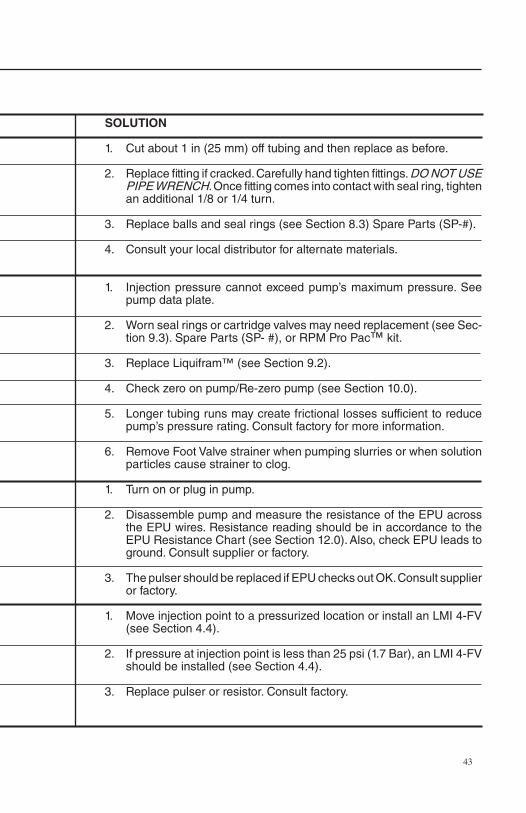
SOLUTION
1. Cut about 1 in (25 mm) off tubing and then replace as before.
2. Replace fitting if cracked. Carefully hand tighten fittings. DO NOT USE PIPE WRENCH. Once fitting comes into contact with seal ring, tighten an additional 1/8 or 1/4 turn.
3. Replace balls and seal rings (see Section 8.3) Spare Parts (SP-#).
4. Consult your local distributor for alternate materials.
1. Injection pressure cannot exceed pump’s maximum pressure. See pump data plate.
2. Worn seal rings or cartridge valves may need replacement (see Sec-tion 9.3). Spare Parts (SP- #), or RPM Pro Pac™ kit.
3. Replace Liquifram™ (see Section 9.2).
4. Check zero on pump/Re-zero pump (see Section 10.0).
5. Longer tubing runs may create frictional losses sufficient to reduce pump’s pressure rating. Consult factory for more information.
6. Remove Foot Valve strainer when pumping slurries or when solution particles cause strainer to clog.
1. Turn on or plug in pump.
2. Disassemble pump and measure the resistance of the EPU across the EPU wires. Resistance reading should be in accordance to the EPU Resistance Chart (see Section 12.0). Also, check EPU leads to ground. Consult supplier or factory.
3. The pulser should be replaced if EPU checks out OK. Consult supplier or factory.
1. Move injection point to a pressurized location or install an LMI 4-FV (see Section 4.4).
2. If pressure at injection point is less than 25 psi (1.7 Bar), an LMI 4-FV should be installed (see Section 4.4).
3. Replace pulser or resistor. Consult factory.
Troubleshooting (continued)
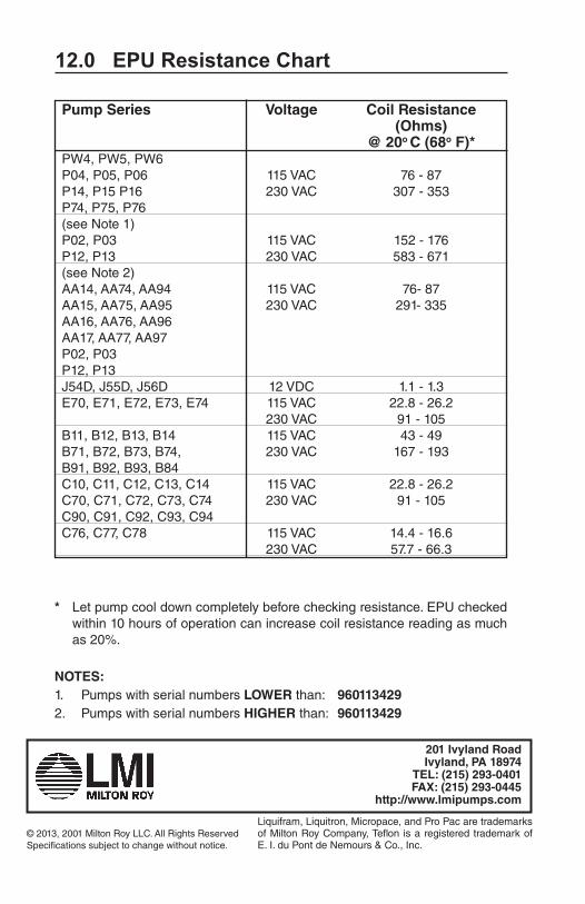
12.0 EPU Resistance Chart
* Let pump cool down completely before checking resistance. EPU checked within 10 hours of operation can increase coil resistance reading as much as 20%.
NOTES:1. Pumps with serial numbers LOWER than: 960113429 2. Pumps with serial numbers HIGHER than: 960113429
Pump Series Voltage Coil Resistance (Ohms) @ 20o C (68o F)* PW4, PW5, PW6 P04, P05, P06 115 VAC 76 - 87 P14, P15 P16 230 VAC 307 - 353 P74, P75, P76 (see Note 1) P02, P03 115 VAC 152 - 176 P12, P13 230 VAC 583 - 671 (see Note 2) AA14, AA74, AA94 115 VAC 76- 87 AA15, AA75, AA95 230 VAC 291- 335 AA16, AA76, AA96 AA17, AA77, AA97 P02, P03 P12, P13 J54D, J55D, J56D 12 VDC 1.1 - 1.3 E70, E71, E72, E73, E74 115 VAC 22.8 - 26.2 230 VAC 91 - 105 B11, B12, B13, B14 115 VAC 43 - 49 B71, B72, B73, B74, 230 VAC 167 - 193 B91, B92, B93, B84 C10, C11, C12, C13, C14 115 VAC 22.8 - 26.2 C70, C71, C72, C73, C74 230 VAC 91 - 105 C90, C91, C92, C93, C94 C76, C77, C78 115 VAC 14.4 - 16.6 230 VAC 57.7 - 66.3
201 Ivyland RoadIvyland, PA 18974
TEL: (215) 293-0401FAX: (215) 293-0445
http://www.lmipumps.com
© 2013, 2001 Milton Roy LLC. All Rights ReservedSpecifications subject to change without notice.
Liquifram, Liquitron, Micropace, and Pro Pac are trademarks of Milton Roy Company, Teflon is a registered trademark of E. I. du Pont de Nemours & Co., Inc.


![Latent Embeddings for Zero-Shot Classification...ods [1, 2, 12, 32] use a unique, globally linear compat-ibility function for all types of images. However, learn-ing a linear compatibility](https://img.pdfslide.net/doc/110x75/5fecbfa0de09b3507e12dd9e/latent-embeddings-for-zero-shot-classification-ods-1-2-12-32-use-a-unique.jpg)