Embed Size (px)
Citation preview

1/17 EN
August 2007 IM_Aprot EN.doc
Instruction Manual AquaProtect T1
AquaProtect T1- Instantaneous AquaProtect T1-Semi-Instantaneous

2/17 EN
August 2007 IM_Aprot EN.doc
Contents Page General 3 General information ............................................................... 3 Installation and connection .................................................... 3 Safety information ……………............................................. 5 Installation 6 AquaProtect T1- I ## P .…...….............................................. 7 AquaProtect T1- S.I. ## P ...................................................... 8 Operation 9 Flow schematics / settings……………………………………… 9 Permanent operation …………………………………………… 11 Temperature ……………………………………………………... 11 Net disinfection / circulation ……………………………………. 12 Commissioning ....................................................................... 12 Decommissioning, faults, dismantling ………………………… 13 Service/maintenance 14 Specifications 14 AquaProtect T1- I ## P …………………………………………. 14 AquaProtect T1- S.I. ## P ……………………………………… 14 Design drawings.......................................................................15/16 Legionella 17
You can reach us at the following address any time: www.alfalaval.com
3/17 EN
August 2007 IM_Aprot EN.doc
General information Alfa Laval owns the copyright to these instructions. Details, pictures and drawings contained in these instructions may not be reproduced, distributed or sold for competition purposes or disclosed to others without authorisation. Alfa Laval reserves the right, without prior notification, to make technical changes compared with the illustrations and information contained in these instructions, should it consider it necessary for improving the Compact system. These instructions provide important information that is necessary to ensure that the system is both reliable and safe. The operating/installation personnel must have access to these instructions. Therefore, please make sure that that a copy of these instructions is available in plenty of time. If the installation is sold, or there is a change of owner, please pass on these instructions to the new owner. Please let us have the name and address of the new owner for the unlikely event that we need to contact them regarding the safety of the installation. Read these instructions carefully before installing the equipment. Pay particular attention to the safety information.
Intended use The AquaProtect T (APT) is a domestic hot water disinfection unit which eradicates Legionella in potable water systems by heating the water up to 70°C. It is used to heat and store potable water for normal use in potable water supply systems and is suitable for connecting to all heating installations as boilers and district heating systems for group or central drinking water supplies. By combining hot water storage tanks of different sizes with the APT of different power ratings, depending on the choice made, continuous outputs of 3 m3/h to 13 m3/h and peak extractions of approx. up to 30m3/h are possible (reference temperature 55°C). The following laws and technical rules are taken into account when designing and choosing the components of the APT: DESP 97/23 Art.3., NF 15100, ACS certified components. Furthermore, when installing and connecting the unit, you may refer to lacal rules and recommendations, as DTU in France. Using the equipment as intended also includes following these operating instructions and maintaining the set values and maintenance conditions specified.
Misuse Any use that exceeds the use described above is misuse. The manufacturer is not liable for damage resulting from misuse. The operator bears the risk. Please keep the order data/article numbers of the system handy so that we can deal with your needs and spares orders promptly. Installation and connection: NB: please check the system delivered for completeness and possible damage in transit before transferring it to the place where it is to be installed. Important: The system may only be installed and commissioned by a specialist company, which is then responsible for the correct installation, connection and the equipment. Some of the components supplied are very heavy and have a high centre of gravity. Please transport these parts carefully and only use suitable equipment, e.g. forklift, crane, lifting truck.
4/17 EN
August 2007 IM_Aprot EN.doc
Space required Install the system in a room that is protected from frost, flooding and is adequately ventilated. The maximum admissible temperature in the room where the system is installed must not exceed 40°C. Make sure that there is adequate space between the system and the wall and other components to allow maintenance and inspection (minimum 60 cm).
Substrate/foundation/load-bearing capacity The load-bearing capacity of the substrate must be adequate for the weight of the system (see delivery documents. Alignment Set up the system on the site and align horizontally. If the substrate is soft, place suitable shims under the foot ring/frame feet so that the system does not sink in.
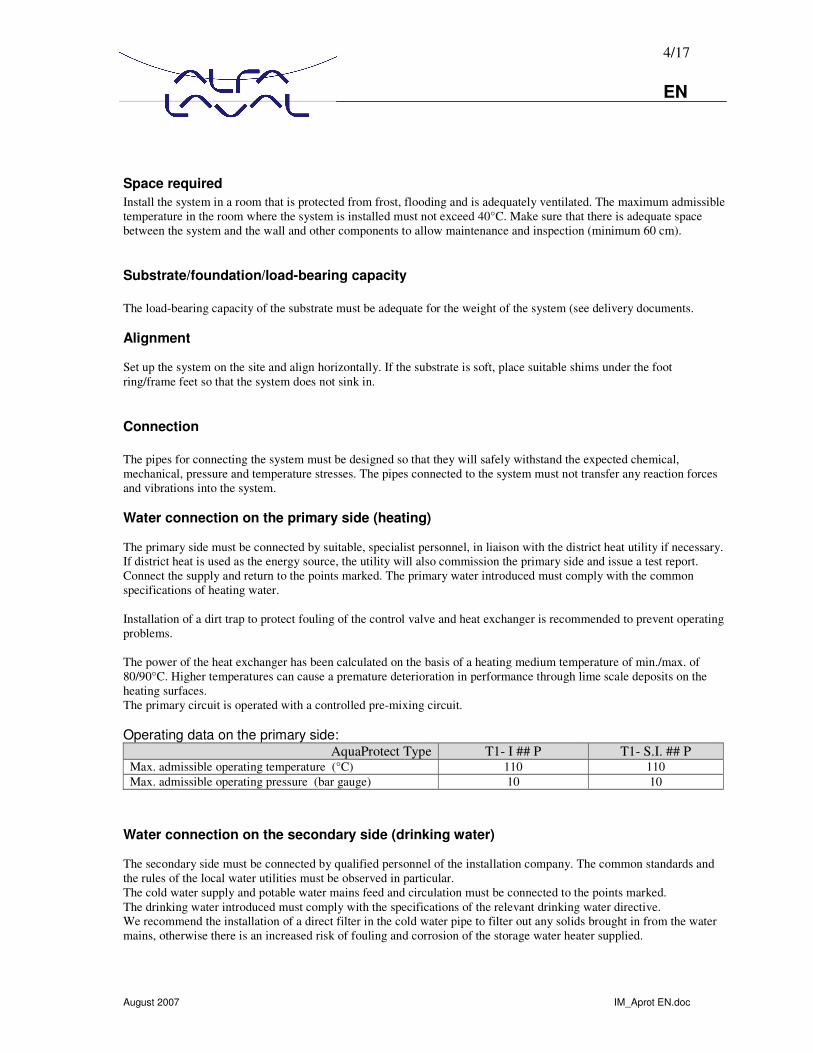
Connection The pipes for connecting the system must be designed so that they will safely withstand the expected chemical, mechanical, pressure and temperature stresses. The pipes connected to the system must not transfer any reaction forces and vibrations into the system. Water connection on the primary side (heating) The primary side must be connected by suitable, specialist personnel, in liaison with the district heat utility if necessary. If district heat is used as the energy source, the utility will also commission the primary side and issue a test report. Connect the supply and return to the points marked. The primary water introduced must comply with the common specifications of heating water. Installation of a dirt trap to protect fouling of the control valve and heat exchanger is recommended to prevent operating problems. The power of the heat exchanger has been calculated on the basis of a heating medium temperature of min./max. of 80/90°C. Higher temperatures can cause a premature deterioration in performance through lime scale deposits on the heating surfaces. The primary circuit is operated with a controlled pre-mixing circuit. Operating data on the primary side:
AquaProtect Type T1- I ## P T1- S.I. ## P Max. admissible operating temperature (°C) 110 110 Max. admissible operating pressure (bar gauge) 10 10
Water connection on the secondary side (drinking water) The secondary side must be connected by qualified personnel of the installation company. The common standards and the rules of the local water utilities must be observed in particular. The cold water supply and potable water mains feed and circulation must be connected to the points marked. The drinking water introduced must comply with the specifications of the relevant drinking water directive. We recommend the installation of a direct filter in the cold water pipe to filter out any solids brought in from the water mains, otherwise there is an increased risk of fouling and corrosion of the storage water heater supplied.
5/17 EN
August 2007 IM_Aprot EN.doc
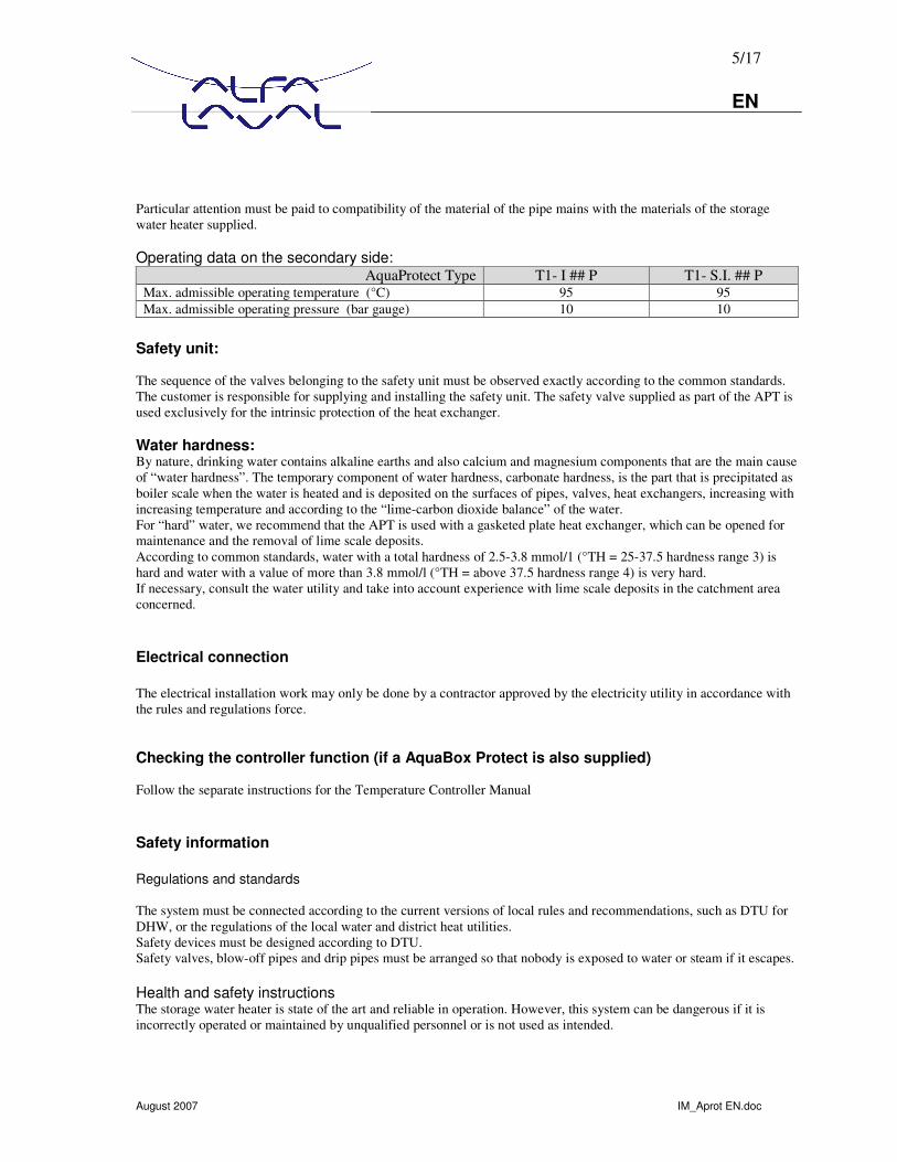
Particular attention must be paid to compatibility of the material of the pipe mains with the materials of the storage water heater supplied. Operating data on the secondary side:
AquaProtect Type T1- I ## P T1- S.I. ## P Max. admissible operating temperature (°C) 95 95 Max. admissible operating pressure (bar gauge) 10 10
Safety unit: The sequence of the valves belonging to the safety unit must be observed exactly according to the common standards. The customer is responsible for supplying and installing the safety unit. The safety valve supplied as part of the APT is used exclusively for the intrinsic protection of the heat exchanger. Water hardness: By nature, drinking water contains alkaline earths and also calcium and magnesium components that are the main cause of “water hardness”. The temporary component of water hardness, carbonate hardness, is the part that is precipitated as boiler scale when the water is heated and is deposited on the surfaces of pipes, valves, heat exchangers, increasing with increasing temperature and according to the “lime-carbon dioxide balance” of the water. For “hard” water, we recommend that the APT is used with a gasketed plate heat exchanger, which can be opened for maintenance and the removal of lime scale deposits. According to common standards, water with a total hardness of 2.5-3.8 mmol/1 (°TH = 25-37.5 hardness range 3) is hard and water with a value of more than 3.8 mmol/l (°TH = above 37.5 hardness range 4) is very hard. If necessary, consult the water utility and take into account experience with lime scale deposits in the catchment area concerned.
Electrical connection The electrical installation work may only be done by a contractor approved by the electricity utility in accordance with the rules and regulations force. Checking the controller function (if a AquaBox Protect is also supplied) Follow the separate instructions for the Temperature Controller Manual
Safety information Regulations and standards The system must be connected according to the current versions of local rules and recommendations, such as DTU for DHW, or the regulations of the local water and district heat utilities. Safety devices must be designed according to DTU. Safety valves, blow-off pipes and drip pipes must be arranged so that nobody is exposed to water or steam if it escapes. Health and safety instructions The storage water heater is state of the art and reliable in operation. However, this system can be dangerous if it is incorrectly operated or maintained by unqualified personnel or is not used as intended.

6/17 EN
August 2007 IM_Aprot EN.doc
Anyone responsible for its operation and maintenance must have read and understood the health and safety information. The system, particularly its safety equipment, many only be operated and maintained by people (qualified people) who are fully conversant with it and have been informed of the dangers. If you are not sure about something, ask your manager or the system supplier or manufacturer. The relevant regulations and also the other generally recognised rules must be observed. Never work in a way that prejudices the safety of the system. In principle, no safety equipment should be removed, taken out of service or adjusted without knowledge of the standards and a qualified person in attendance. The safety equipment protects against serious physical damage (burns, electric shock, etc.). If damage to the system or defects are recognised, particularly those affecting the safety equipment, expansion tanks, etc. and if unusual noises or smells develop, switch the system off and inform your supplier. In principle any service and cleaning work on the system must only be done when it is stationary. The system must be protected against unauthorised operation.
Special danger points If leaks occur on the primary side and the temperature is above 100°C, hot steam will escape. Contact with hot steam can cause considerable scalding. Therefore, avoid any contact with the steam. Remember that even after it has been switched off, the system will stay hot for some time longer and you may burn yourself. All parts of the system that carry water are hot in operation. Contact with hot parts of the system can cause serious burns. Avoid any contact with hot parts of the system. Do not remove any water. The pump, servo motor for the throughput/mixing valve, heating controller and control sensor are connected to the mains. Water spray or leaks can make the entire station dangerously live. Therefore, when working on the system, make sure that the entire system is dead. Pull the mains plug out of the socket. Local safety and accident prevention relations apply to installation, connection, operation and repair of the system in each case. Warning against your own conversions and changes: For safety reasons, you must not convert or modify the system yourself. The guarantee covering the system will inevitably lapse if you do.
Installation The system must be installed according to the following diagrams : Annotation:
The buffer vessel can be sited as space is available next to the heat exchanger module. All pipe works between the buffer vessel and the heat exchanger module as well as the circulation pump are not a part of the AquaProtect delivery.

7/17 EN
August 2007 IM_Aprot EN.doc
AquaProtect T1- I ## P :
Heat exchanger modul
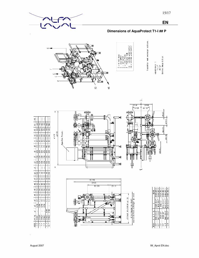
C Cold water / Eau froide D Hot water / Sortie ECS E Circulation / Bouclage F To top of tank / Vers haut du ballon G Disinfected water out / Sortie eau pasteurisé
F
G
C
E
HS Primary flow
HR Primary return
D
8/17 EN
August 2007 IM_Aprot EN.doc
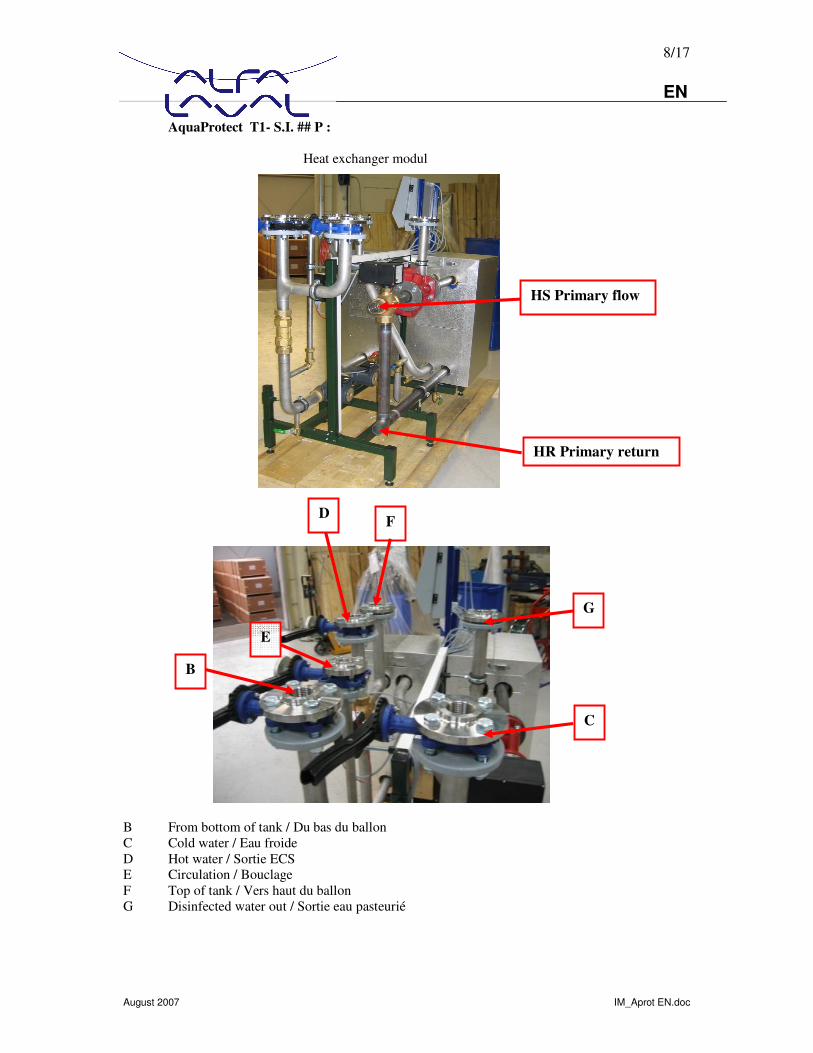
AquaProtect T1- S.I. ## P :
Heat exchanger modul
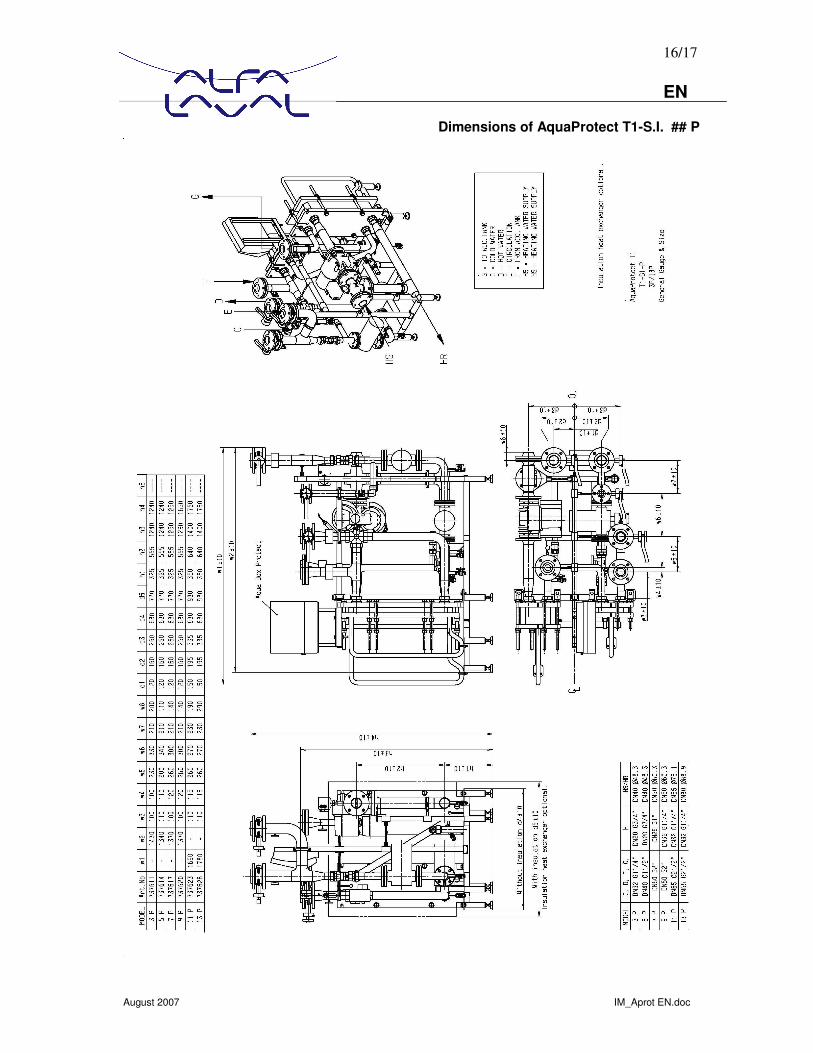
B From bottom of tank / Du bas du ballon C Cold water / Eau froide D Hot water / Sortie ECS E Circulation / Bouclage F Top of tank / Vers haut du ballon G Disinfected water out / Sortie eau pasteurié
F
G
C
E
HS Primary flow
HR Primary return
D
B

9/17 EN
August 2007 IM_Aprot EN.doc
Operation Function diagrams The position of the connections on the tank is given in the relevant tank dimension sheets or on the rating plates on the tank itself. The illustration in the following examples is only a basic diagram. AquaProtect T1 - I ## P
Caption C Cold water / Eau de froide AV balancing valve / Vanne d`équilibrage D Hot water / Sortie ECS TS safety temperature limiter / Thermostat
de sécurité E Circulation / Bouclage F Top of tank / Vers haut du ballon Settings: The factory pre-settings are: - 70°C for the pasteurization temperature (PT100) on the controller AquaBox Protect - 55°C for the net-supply temperature (PT1000) on the integrated controller of the actuator of the secondary mixing valve. - 65°C on the safety temperature limiter (TS)
10/17 EN
August 2007 IM_Aprot EN.doc
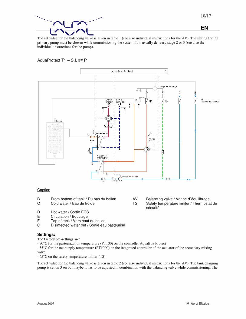
The set value for the balancing valve is given in table 1 (see also individual instructions for the AV). The setting for the primary pump must be chosen while commissioning the system. It is usually delivery stage 2 or 3 (see also the individual instructions for the pump). AquaProtect T1 – S.I. ## P
Caption B From bottom of tank / Du bas du ballon AV Balancing valve / Vanne d`équilibrage C Cold water / Eau de froide TS Safety temperature limiter / Thermostat de
sécurité D Hot water / Sortie ECS E Circulation / Bouclage F Top of tank / Vers haut du ballon G Disinfected water out / Sortie eau pasteurisé Settings: The factory pre-settings are: - 70°C for the pasteurization temperature (PT100) on the controller AquaBox Protect - 55°C for the net-supply temperature (PT1000) on the integrated controller of the actuator of the secondary mixing valve. - 65°C on the safety temperature limiter (TS)
The set value for the balancing valve is given in table 2 (see also individual instructions for the AV). The tank charging pump is set on 3 on but maybe it has to be adjusted in combination with the balancing valve while commissioning. The

11/17 EN
August 2007 IM_Aprot EN.doc
setting for the primary pump must be chosen while commissioning the system. It is usually delivery stage 2 or 3 (see also the individual instructions for the pump). AquaProtetc T1-S.I. with multiple buffer tanks
If several hot water storage tanks are operated within a APT, we recommend that the tanks are connected in series. In this case, the cold water connection of tank 1 is connected to the mains connection (hot water) of tank 2.
Permanent operation of AquaProtect T systems The aim of the AquaProtect T is the safe eradication of all Legionella inside the drinking water to ensure the protection of health at any time. That means the APT must be in operation 24h the day. This requires an uninterrupted energy supply on primary side at the right temperature level and an uninterrupted operation of the circulation pump. The protection of health takes priority over energy savings.
Temperatures The requirements laid down in the general pasteurization standards with regard to temperature control in the potable water on the secondary side require an uninterrupted energy supply at constant temperature on the primary side. In this case, the primary heating circuit can be fed from boiler installations, district heat, co-generation power stations, heat recovery systems, solar energy, etc. It must be ensured that the heat exchanger is provided with sufficient energy at the temperature level required.

12/17 EN
August 2007 IM_Aprot EN.doc
Primary temperatures:
AquaProtect T1 - I T1 - S.I. Min. supply temperature °C 80°C 80°C
Net-disinfection Acessory to the continuous pasteurization of the drinking water the AquaBox offers the possibility to disinfect/pasteurize the entire DHW pipe net. This function allows to run the entire net from the AquaProtect to all taps and the circulation line back to the AquaProtect at 70°C pasteurization temperature. This function >Anti-Bacteria Thermal Treatment < can be set during commissioning the APT. More detailed information can be found in the separate instruction manual of the AquaBox. We recommend to set this function in operation. The choice of the right settings like frequency, hour of start, duration etc.. depends on different net parameters as largeness, complexity, age and frequency of use. If there is a risk of re-infection given by dead ends, arms with low frequency of use, fouling inside the net etc. then we recommend to ascertain the right frequency set for the Anti-bacteria function by bacteriological checkups of the water. Contac with hot water of 70°C can cause considerable scalding. It is therefore strongly recommended all precautions be taken in order to avoid accidental injury of users. Circulation Flow rate The entire circulation backflow goes through the two-stage pasteurization. There is no bypass between circulation and net supply. This ensures that all circulated water is pasteurized all the time. The circulation back flow should not exceed a third of the instant flow rate. Heat load Usually the temperature drop of the circulated water inside the pipe net is approx. 5°C. But it can happen that the temperature drop in old large pipe nets is more than 15°C. This heat loss will reduce the capacity output to the taps and secondly reduce the charging capacity to the buffer vessel connected to the AquaProtect T1-S.I.
Commissioning When charging the system with the operating media for the first time, make sure that all screw connections are properly tightened, tighten any loose connections with a suitable tool and make sure that all seals are firmly seated and leak-tight, particularly the flange seal on the buffer tank.
Flushing and charging the system Secondary side Qualified staff of the installation contractor must flush and fill the secondary side. Make sure that no dirt is introduced into the system and check for controlled venting. The charging pressure must not exceed the set opening pressure of the safety valve. The opening pressure details are given on the safety valve. If the opening pressure is exceeded, the room will be flooded.
Primary side The primary side must be flushed and filled by the contractor’s qualified personnel, in liaison with the district heat utility if necessary. Otherwise, the same as described for the secondary side applies. Please remember that if there are any leaks on the primary side, there is a risk of scalding through hot water.
13/17 EN
August 2007 IM_Aprot EN.doc
Decommissioning/faults/dismantling Switching off Switch off the operating switch, if necessary pull the plug out of the circuit or switch off the system so that it is completely dead.
Faults NB: risk of scalding If there are any leaks on the primary side, water or steam with temperatures above 100°C can escape. Remember, even after the system has been switched off, it will still remain hot for some time, so you can burn yourself on it. The pump, servo motor for the motorised valve, AquaBox and control sensor are connected to the mains voltage. Spray or leaks can make the entire station dangerously live. 1. Take the system out of service, i.e. interrupt the mains voltage by pulling out the plug or switching off the main
fuse 2. Inform the company responsible for repairing mechanical or electronic faults 3. Do not try to trace or remedy the fault yourself.
Re-commissioning after a fault After a fault, the system must be re-commissioned by qualified personnel, in liaison with the district heat utility if necessary. The system must be re-commissioned according to the “Commissioning” section.
Measures after a long shutdown After a fault, the system must be re-commissioned by qualified personnel, in liaison with the district heat utility if necessary. Check the dirt traps installed and clean if necessary. Otherwise proceed according to the “Commissioning” section.
Dismantling The following measures are necessary for dismantling the system: 1. Switch off the main power supply and prevent it from being switched on again accidentally. 2. Switch off the primary side, in liaison with the district heat utility if necessary. 3. Turn off the cold water supply 4. Allow the system to cool down before starting the dismantling work 5. Drain the system 6. Dismantle the system If the system is taken out of service for the last time or scrapped, make sure that it is disposed of in the correct manner. Arrange to send parts that can be recycled to the manufacturer concerned.
14/17 EN
August 2007 IM_Aprot EN.doc
Operation General After the system has been flushed, filled and the operating flows and temperatures have been correctly set, it works automatically. If you wish to change the operating parameters, following the individual instructions for the components concerned. These operating instructions will allow the contractor’s qualified personnel to set the equipment.
Any defects found must be reported immediately in writing Service / maintenance The leak-tightness of all screw and flange connection seals must be checked at regular intervals. Because of constantly fluctuating temperature loads, i.e. topping up with cold water when water is extracted and re-charging to tank temperature, the elasticity of the seal materials used suffers during the life of the system. The tension of the screw connections can decline at the same time, resulting in leaks. Therefore, after commissioning the system, we recommend that you check all screw and flange connection seals visually and physically at the same interval as the necessary safety valve function test. Other maintenance information is provided in the individual instructions for the components supplied.
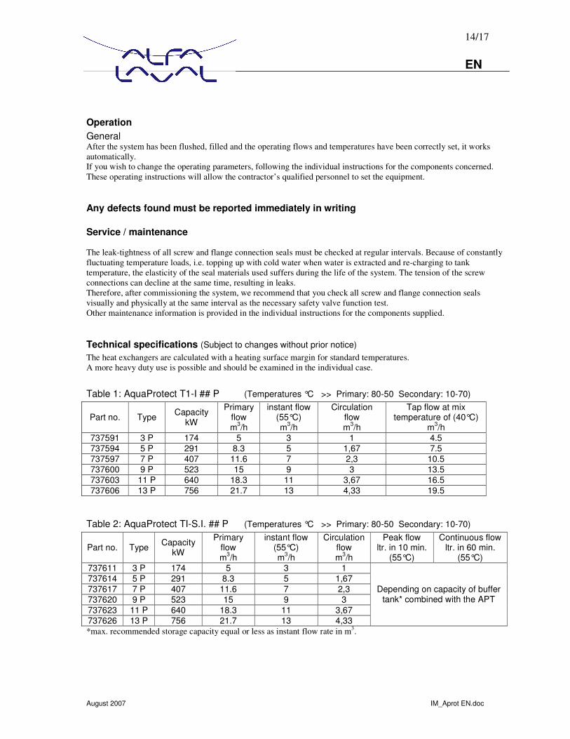
Technical specifications (Subject to changes without prior notice) The heat exchangers are calculated with a heating surface margin for standard temperatures. A more heavy duty use is possible and should be examined in the individual case.
Table 1: AquaProtect T1-I ## P (Temperatures °C >> Primary: 80-50 Secondary: 10-70)
Part no. Type Capacity kW
Primary flow m3/h
instant flow (55°C) m3/h
Circulation flow m3/h
Tap flow at mix temperature of (40°C)
m3/h 737591 3 P 174 5 3 1 4.5 737594 5 P 291 8.3 5 1,67 7.5 737597 7 P 407 11.6 7 2,3 10.5 737600 9 P 523 15 9 3 13.5 737603 11 P 640 18.3 11 3,67 16.5 737606 13 P 756 21.7 13 4,33 19.5
Table 2: AquaProtect TI-S.I. ## P (Temperatures °C >> Primary: 80-50 Secondary: 10-70)
Part no. Type Capacity kW
Primary flow m3/h
instant flow (55°C) m3/h
Circulation flow m3/h
Peak flow ltr. in 10 min.
(55°C)
Continuous flow ltr. in 60 min.
(55°C) 737611 3 P 174 5 3 1 737614 5 P 291 8.3 5 1,67 737617 7 P 407 11.6 7 2,3 737620 9 P 523 15 9 3 737623 11 P 640 18.3 11 3,67 737626 13 P 756 21.7 13 4,33
Depending on capacity of buffer tank* combined with the APT
*max. recommended storage capacity equal or less as instant flow rate in m3.
15/17 EN
August 2007 IM_Aprot EN.doc
Dimensions of AquaProtect T1-I ## P
16/17 EN
August 2007 IM_Aprot EN.doc
Dimensions of AquaProtect T1-S.I. ## P
17/17 EN
August 2007 IM_Aprot EN.doc
Legionella Legionella bacteria are common and can be found naturally in environmental water sources such as rivers, lakes and reservoirs, usually in low numbers. The bacteria enter our water systems with the cold water delivered from the mains. They can sometimes cause a risk to humans if people get exposed to them through humidified contaminated air (aerosol). This wet air conditions can be found e.g. in bathes and shower rooms, spas, pools, air conditioning units etc..
People become infected when they breathe in air that contains tiny droplets of water known as aerosols, inside of which are the Legionella bacteria. If the bacteria get inhaled into the lungs they can cause infection. Legionnaires’ disease cannot be got from water you drink that enters your stomach in the normal way – the bacterium has to get into the lungs through breathing it in. The illness is not spread from person to person. Legionnaires' disease is an uncommon form of pneumonia. The disease has no particular clinical features that clearly distinguish it from other types of pneumonia, and laboratory investigations must be carried out to confirm the diagnosis. It normally takes between 2-10 days to develop symptoms (typically five to six days but very rarely some cases may take two to three weeks to develop symptoms). Patients usually start with a dry cough, fever, headache and sometimes diarrhoea and many people go on to get pneumonia. People over the age of 50 are more at risk than younger people and males more than females. Effective antibiotic treatment is available if the diagnosis is made early in the illness. Deaths occur in about 5-15% of travellers who get the disease, depending on their age and individual health status. Smokers are more at risk than non-smokers.
The organisms can survive in a wide range of conditions, including temperatures of 0 to 63°C, pH of 5.0 to 8.5, and dissolved oxygen concentrations of 0.2 to 15 ppm in water. Temperature is a critical determinant for Legionella proliferation. Colonization of the hot water system is more likely if the temperatures are between 40 and 50°C. Legionella and other microorganisms become attached to surfaces in an aquatic environment forming a biofilm. Legionella has been shown to attach to and colonize various materials found in water systems including plastics and rubber. Organic sediments, scale, and inorganic precipitates provide Legionella with a surface for attachment and a protective barrier. Interestingly, the growth of other environmental organisms is stimulated by organic sediment, which in turn leads to the formation of by-products that stimulate the growth of Legionella.
The thermal disinfection (pasteurization) at 70°C of the tap water combined with the periodically net disinfection at the same temperature is the safest way to keep the hot water system free of Legionella. It effects in the entire system on the water as well as on scales and fouling.