Embed Size (px)
Citation preview
Instruction Manual(COB LED Package)
Product Description
Handling COB LED package
Soldering Process
Mechanical Assembly
Thermal Design
Electrical Connection
Chemical Incompatibility
Solutions
CONTENTS1.
2.
3.
4.
5.
6.
7.
8.
P.2
P.3
P.6
P.7
P.10
P.11
P.14
P.15
CITIZEN ELECTRONICS CO., LTD.1-23-1, Kamikurechi, Fujiyoshida-shi, Yamanashi, 403-0001, Japan Tel. +81-555-23-4121 http://ce.citizen.co.jp
Copyright © 2010 CITIZEN ELECTRONICS CO., LTD. All Rights reserved. Ref.CE-P2468 03/13_R1(1213)
2 Copyright © 2010 CITIZEN ELECTRONICS CO., LTD. All Rights reserved.
1,Product Description
1-1, Introduction
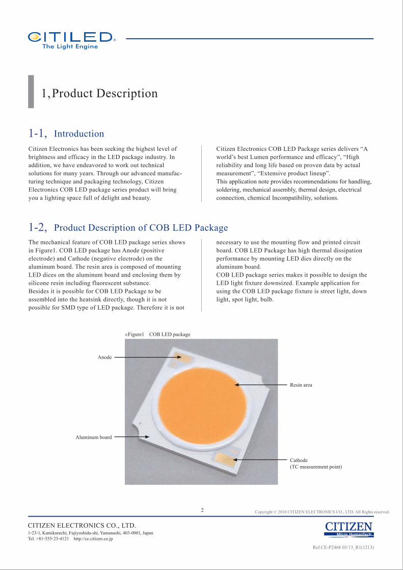
1-2, Product Description of COB LED PackageThe mechanical feature of COB LED package series shows in Figure1. COB LED package has Anode (positive electrode) and Cathode (negative electrode) on the aluminum board. The resin area is composed of mounting LED dices on the aluminum board and enclosing them by silicone resin including fluorescent substance.Besides it is possible for COB LED Package to be assembled into the heatsink directly, though it is not possible for SMD type of LED package. Therefore it is not
necessary to use the mounting flow and printed circuit board. COB LED Package has high thermal dissipation performance by mounting LED dies directly on the aluminum board. COB LED package series makes it possible to design the LED light fixture downsized. Example application for using the COB LED package fixture is street light, down light, spot light, bulb.
Cathode(TC measurement point)
Resin area
Anode
Aluminum board
■Figure1 COB LED package
Citizen Electronics has been seeking the highest level of brightness and efficacy in the LED package industry. In addition, we have endeavored to work out technical solutions for many years. Through our advanced manufac-turing technique and packaging technology, Citizen Electronics COB LED package series product will bring you a lighting space full of delight and beauty.
Citizen Electronics COB LED Package series delivers “A world’s best Lumen performance and efficacy”, “High reliability and long life based on proven data by actual measurement”, “Extensive product lineup”.This application note provides recommendations for handling, soldering, mechanical assembly, thermal design, electrical connection, chemical Incompatibility, solutions.
CITIZEN ELECTRONICS CO., LTD.1-23-1, Kamikurechi, Fujiyoshida-shi, Yamanashi, 403-0001, Japan Tel. +81-555-23-4121 http://ce.citizen.co.jp
Ref.CE-P2468 03/13_R1(1213)
3 Copyright © 2010 CITIZEN ELECTRONICS CO., LTD. All Rights reserved.
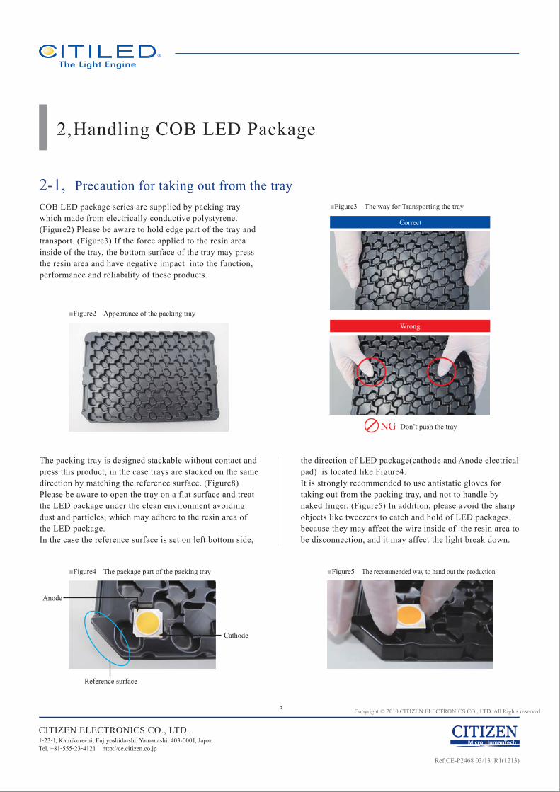
The packing tray is designed stackable without contact and press this product, in the case trays are stacked on the same direction by matching the reference surface. (Figure8) Please be aware to open the tray on a flat surface and treat the LED package under the clean environment avoiding dust and particles, which may adhere to the resin area of the LED package. In the case the reference surface is set on left bottom side,
the direction of LED package(cathode and Anode electrical pad) is located like Figure4.It is strongly recommended to use antistatic gloves for taking out from the packing tray, and not to handle by naked finger. (Figure5) In addition, please avoid the sharp objects like tweezers to catch and hold of LED packages, because they may affect the wire inside of the resin area to be disconnection, and it may affect the light break down.
■Figure2 Appearance of the packing tray
Wrong
Correct
■Figure3 The way for Transporting the tray
■Figure4 The package part of the packing tray ■Figure5 The recommended way to hand out the production
2,Handling COB LED Package
2-1, Precaution for taking out from the trayCOB LED package series are supplied by packing tray which made from electrically conductive polystyrene. (Figure2) Please be aware to hold edge part of the tray and transport. (Figure3) If the force applied to the resin area inside of the tray, the bottom surface of the tray may press the resin area and have negative impact into the function, performance and reliability of these products.
CITIZEN ELECTRONICS CO., LTD.1-23-1, Kamikurechi, Fujiyoshida-shi, Yamanashi, 403-0001, Japan Tel. +81-555-23-4121 http://ce.citizen.co.jp
Reference surface
Cathode
Anode
NG Don’t push the tray
Ref.CE-P2468 03/13_R1(1213)
4 Copyright © 2010 CITIZEN ELECTRONICS CO., LTD. All Rights reserved.
CITIZEN ELECTRONICS CO., LTD.1-23-1, Kamikurechi, Fujiyoshida-shi, Yamanashi, 403-0001, Japan Tel. +81-555-23-4121 http://ce.citizen.co.jp
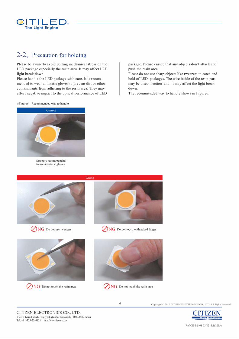
■Figure6 Recommended way to handle
Correct
Strongly recommended to use antistatic gloves
NG Do not touch with naked finger
NG Do not touch the resin area
NG Do not use tweezers
Wrong
NG Do not touch the resin area
2-2, Precaution for holdingPlease be aware to avoid putting mechanical stress on the LED package especially the resin area. It may affect LED light break down. Please handle the LED package with care. It is recom-mended to wear antistatic gloves to prevent dirt or other contaminants from adhering to the resin area. They may affect negative impact to the optical performance of LED
package. Please ensure that any objects don’t attach and push the resin area.Please do not use sharp objects like tweezers to catch and hold of LED packages. The wire inside of the resin part may be disconnection and it may affect the light break down. The recommended way to handle shows in Figure6.
Ref.CE-P2468 03/13_R1(1213)
5 Copyright © 2010 CITIZEN ELECTRONICS CO., LTD. All Rights reserved.
CITIZEN ELECTRONICS CO., LTD.1-23-1, Kamikurechi, Fujiyoshida-shi, Yamanashi, 403-0001, Japan Tel. +81-555-23-4121 http://ce.citizen.co.jp
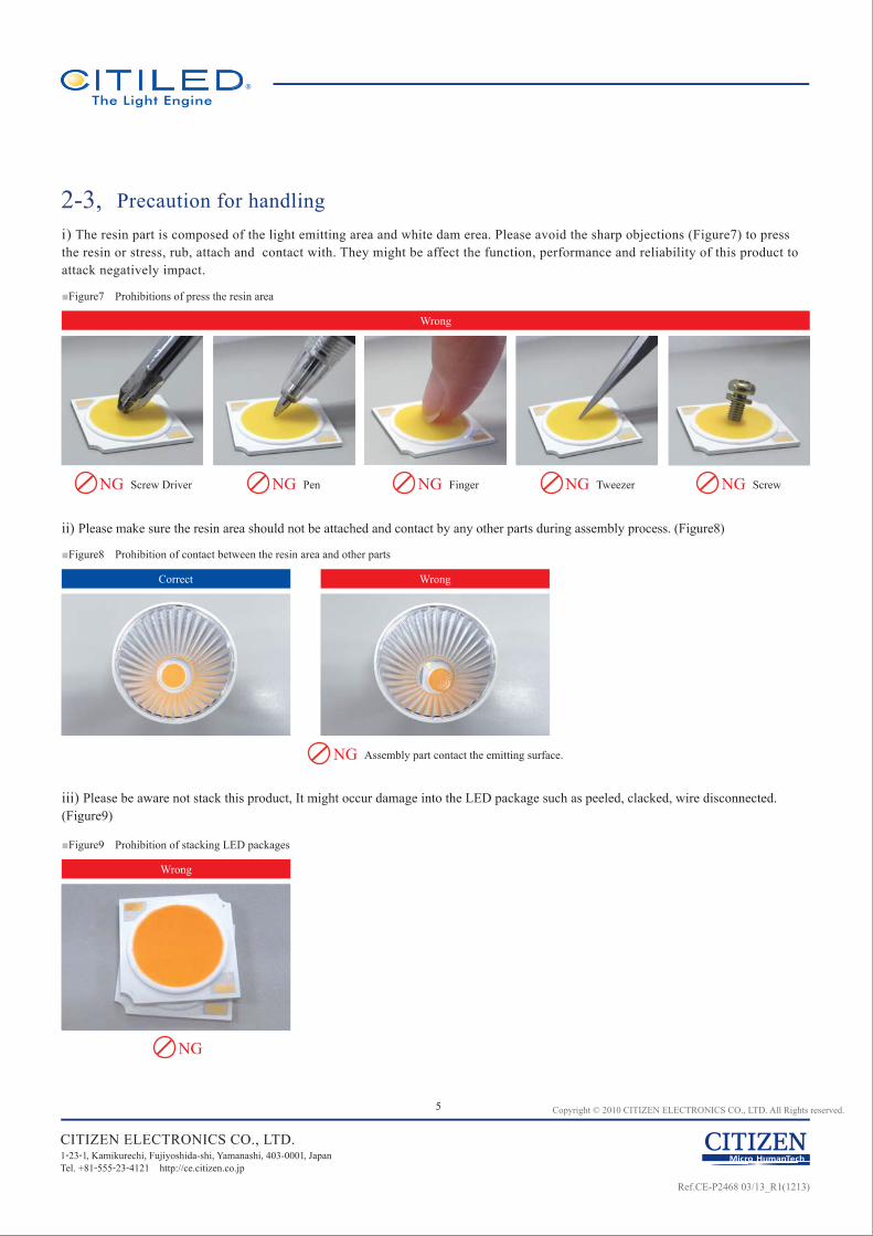
i) The resin part is composed of the light emitting area and white dam erea. Please avoid the sharp objections (Figure7) to press the resin or stress, rub, attach and contact with. They might be affect the function, performance and reliability of this product to attack negatively impact.
ii) Please make sure the resin area should not be attached and contact by any other parts during assembly process. (Figure8)
iii) Please be aware not stack this product, It might occur damage into the LED package such as peeled, clacked, wire disconnected. (Figure9)
2-3, Precaution for handling
■Figure7 Prohibitions of press the resin area
Wrong
■Figure8 Prohibition of contact between the resin area and other parts
Correct Wrong
■Figure9 Prohibition of stacking LED packages
Wrong
NG Screw Driver NG Pen
NG Assembly part contact the emitting surface.
NG
NG Finger NG Tweezer NG Screw
Ref.CE-P2468 03/13_R1(1213)

This product is not adaptable to reflow process. The conditions below are recommended for soldering.
No external force shall be applied to the resin area. In addition, please ensure that the soldering bit has no contact with the resin area.Next process of soldering should be carried out after the product has returned to ambient temperature.
Recommended soldering conditionOut put of soldering iron : Soldering bit temperature shall be 350℃ or lessHeating time : 3.5 seconds or less per land
Make sure following the items.1, 2,3,4,
5, 6,
7,
8,
9,
10,
The soldering fillet is formed.The core part is solderad well.The solder has shiny appearance.There is not the protuberance or extreme raised on soldering.The lead wire don’t floot up from the pad.The solder covers well around outside and the side surface of lead wire.There is not attach soldering (e.g. soldering ball, soldering flux) at out of the designated pad for soldering extremely.The solder lands on the 2/3 space of pad of LED package board.The conductive part of lead wire doesn’t land on the outside of the soldering pad.The height of the conductive part of lead wire and the soldering don’t put over the height of the insulated plastic part.
3, Soldering Process
3-1, Recommended Soldering process
3-2, Recommended Soldering Appearance3-2-1, Appearance Condition of Soldering Lead Wire
Not over the conductive part of wire from soldering pad.
Please refer the positioning between the lead wire and the soldering pad at pictures below.(Figure10)
3-2-2, Position of Soldering Lead Wire on the soldering pad
■Figure10 The way for soldering lead wire
Correct
Wrong
6 Copyright © 2010 CITIZEN ELECTRONICS CO., LTD. All Rights reserved.
CITIZEN ELECTRONICS CO., LTD.1-23-1, Kamikurechi, Fujiyoshida-shi, Yamanashi, 403-0001, Japan Tel. +81-555-23-4121 http://ce.citizen.co.jp
NG Over at front edge
NG The conductive part of wire is over from soldering pad.
NG Over at bottom edge
Ref.CE-P2468 03/13_R1(1213)
4-1-1,
7 Copyright © 2010 CITIZEN ELECTRONICS CO., LTD. All Rights reserved.
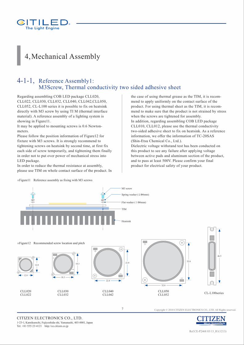
4,Mechanical Assembly
Reference Assembly1: M3Screw, Thermal conductivity two sided adhesive sheet
Regarding assembling COB LED package CLL020, CLL022, CLL030, CLL032, CLL040, CLL042,CLL050, CLL052, CL-L100 series it is possible to fix on heatsink directly with M3 screw by using TI M (thermal interface material). A reference assembly of a lighting system is showing in Figure11.It may be applied to mounting screws is 0.6 Newton-meters.Please follow the position information of Figure12 for fixture with M3 screws. It is strongly recommend to tightening screws on heatsink by second time, at first fix each side of screw temporarily, and tightening them finally in order not to put over power of mechanical stress into LED package.In order to reduce the thermal resistance at assembly, please use TIM on whole contact surface of the product. In
the case of using thermal grease as the TIM, it is recom-mend to apply uniformly on the contact surface of the product. For using thermal sheet as the TIM, it is recom-mend to make sure that the product is not strained by stress when the screws are tightened for assembly.In addition, regarding assembling COB LED package CLL010, CLL012, please use the thermal conductivity two-sided adhesive sheet to fix on heatsink. As a reference information, we offer the information of TC-20SAS (Shin-Etsu Chemical Co., Ltd.).Dielectric voltage withstand test has been conducted on this product to see any failure after applying voltage between active pads and aluminum section of the product, and to pass at least 500V. Please confirm your final product for electrical safety of your product.
■Figure11 Reference assembly as fixing with M3 screws
■Figure12 Recommended screw location and pitch
CITIZEN ELECTRONICS CO., LTD.1-23-1, Kamikurechi, Fujiyoshida-shi, Yamanashi, 403-0001, Japan Tel. +81-555-23-4121 http://ce.citizen.co.jp
M3 screw
Spring washer (≦Φ6mm)
Flat washer (≦Φ6mm)
TIM
Heatsink
CLL020CLL022
CLL030CLL032
CLL040CLL042
CLL050CLL052 CL-L100series
12.8
12.8
18.3
18.3
22.8
22.8
32.0
32.0
46.5
Ref.CE-P2468 03/13_R1(1213)
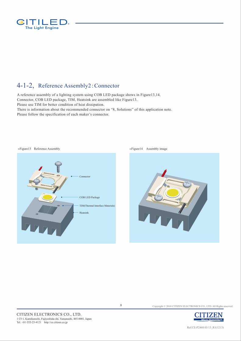
4-1-2,
8 Copyright © 2010 CITIZEN ELECTRONICS CO., LTD. All Rights reserved.
Reference Assembly2 : ConnectorA reference assembly of a lighting system using COB LED package shows in Figure13,14.Connector, COB LED package, TIM, Heatsink are assembled like Figure13.Please use TIM for better condition of heat dissipation.There is information about the recommended connector on “8, Solutions” of this application note.Please follow the specification of each maker’s connector.
■Figure13 Reference Assembly ■Figure14 Assembly image
CITIZEN ELECTRONICS CO., LTD.1-23-1, Kamikurechi, Fujiyoshida-shi, Yamanashi, 403-0001, Japan Tel. +81-555-23-4121 http://ce.citizen.co.jp
Connector
COB LED Package
TIM(Thermal Interface Materials)
Heatsink
Ref.CE-P2468 03/13_R1(1213)
NGOver torque
NGScrew driver
NGScrew
NGPen
NGFinger nail
NG
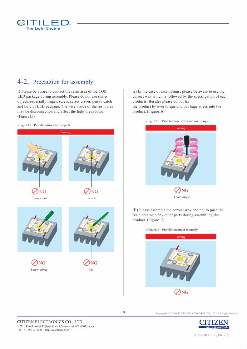
4-2,
9 Copyright © 2010 CITIZEN ELECTRONICS CO., LTD. All Rights reserved.
Precaution for assemblyi) Please be aware to contact the resin area of the COB LED package during assembly. Please do not use sharp objects especially finger, screw, screw driver, pen to catch and hold of LED package. The wire inside of the resin area may be disconnection and affect the light breakdown. (Figure15)
■Figure15 Prohibit using sharp objects■Figure16 Prohibit huge stress and over torque
ii) In the case of assembling , please be aware to use the correct way which is followed by the specification of each products. Besides please do not fix the product by over torque and put huge stress into the product. (Figure16)
■Figure17 Prohibit incorrect assembly
iii) Please assemble the correct way and not to push the resin area with any other parts during assembling the product. (Figure17)
Wrong
WrongWrong
CITIZEN ELECTRONICS CO., LTD.1-23-1, Kamikurechi, Fujiyoshida-shi, Yamanashi, 403-0001, Japan Tel. +81-555-23-4121 http://ce.citizen.co.jp
Ref.CE-P2468 03/13_R1(1213)
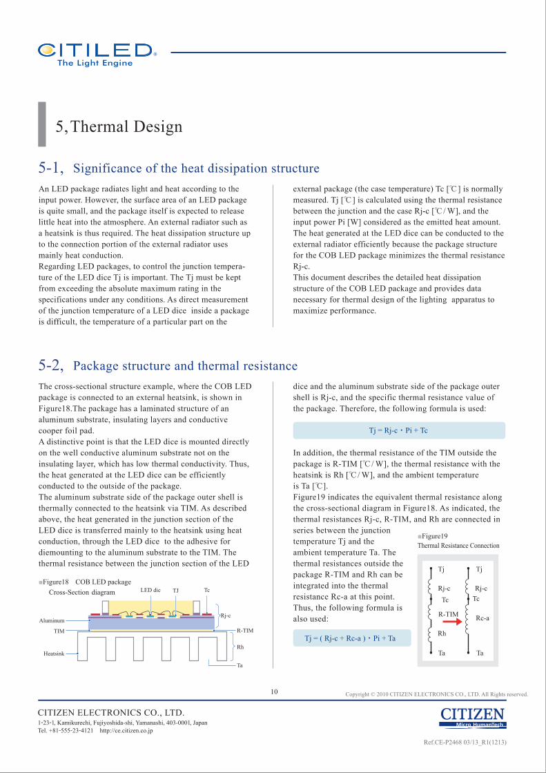
dice and the aluminum substrate side of the package outer shell is Rj-c, and the specific thermal resistance value of the package. Therefore, the following formula is used:
In addition, the thermal resistance of the TIM outside the package is R-TIM [℃ / W], the thermal resistance with the heatsink is Rh [℃ / W], and the ambient temperatureis Ta [℃].Figure19 indicates the equivalent thermal resistance along the cross-sectional diagram in Figure18. As indicated, the thermal resistances Rj-c, R-TIM, and Rh are connected in series between the junction temperature Tj and the ambient temperature Ta. The thermal resistances outside the package R-TIM and Rh can be integrated into the thermal resistance Rc-a at this point.Thus, the following formula is also used:
10 Copyright © 2010 CITIZEN ELECTRONICS CO., LTD. All Rights reserved.
5,Thermal Design
5-1, Significance of the heat dissipation structureAn LED package radiates light and heat according to the input power. However, the surface area of an LED package is quite small, and the package itself is expected to release little heat into the atmosphere. An external radiator such as a heatsink is thus required. The heat dissipation structure up to the connection portion of the external radiator uses mainly heat conduction.Regarding LED packages, to control the junction tempera-ture of the LED dice Tj is important. The Tj must be kept from exceeding the absolute maximum rating in the specifications under any conditions. As direct measurement of the junction temperature of a LED dice inside a package is difficult, the temperature of a particular part on the
external package (the case temperature) Tc [℃] is normally measured. Tj [℃] is calculated using the thermal resistance between the junction and the case Rj-c [℃ / W], and the input power Pi [W] considered as the emitted heat amount.The heat generated at the LED dice can be conducted to the external radiator efficiently because the package structure for the COB LED package minimizes the thermal resistance Rj-c.This document describes the detailed heat dissipation structure of the COB LED package and provides data necessary for thermal design of the lighting apparatus to maximize performance.
5-2, Package structure and thermal resistanceThe cross-sectional structure example, where the COB LED package is connected to an external heatsink, is shown in Figure18.The package has a laminated structure of an aluminum substrate, insulating layers and conductive cooper foil pad.A distinctive point is that the LED dice is mounted directly on the well conductive aluminum substrate not on the insulating layer, which has low thermal conductivity. Thus, the heat generated at the LED dice can be efficiently conducted to the outside of the package.The aluminum substrate side of the package outer shell is thermally connected to the heatsink via TIM. As described above, the heat generated in the junction section of the LED dice is transferred mainly to the heatsink using heat conduction, through the LED dice to the adhesive for diemounting to the aluminum substrate to the TIM. The thermal resistance between the junction section of the LED
■Figure18 COB LED package
■Figure19Thermal Resistance Connection
Tc
Tj Tj
TcRj-c Rj-c
Rc-aR-TIM
Rh
Ta Ta
Tj = ( Rj-c + Rc-a ) ・ Pi + Ta
CITIZEN ELECTRONICS CO., LTD.1-23-1, Kamikurechi, Fujiyoshida-shi, Yamanashi, 403-0001, Japan Tel. +81-555-23-4121 http://ce.citizen.co.jp
Aluminum
LED die TJ Tc
TIM R-TIM
Ta
Heatsink
Rj-c
Rh
Cross-Section diagram
Tj = Rj-c ・ Pi + Tc
Ref.CE-P2468 03/13_R1(1213)
11 Copyright © 2010 CITIZEN ELECTRONICS CO., LTD. All Rights reserved.
6,Electrical Connection
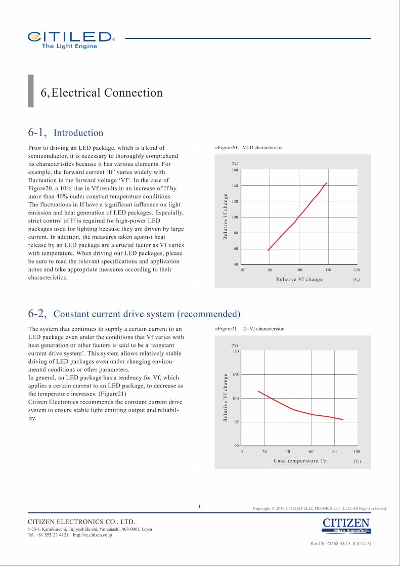
6-1, IntroductionPrior to driving an LED package, which is a kind of semiconductor, it is necessary to thoroughly comprehend its characteristics because it has various elements. For example, the forward current ‘If’ varies widely with fluctuation in the forward voltage ‘Vf’. In the case of Figure20, a 10% rise in Vf results in an increase of If by more than 40% under constant temperature conditions.The fluctuations in If have a significant influence on light emission and heat generation of LED packages. Especially, strict control of If is required for high-power LED packages used for lighting because they are driven by large current. In addition, the measures taken against heat release by an LED package are a crucial factor as Vf varies with temperature. When driving our LED packages, please be sure to read the relevant specifications and application notes and take appropriate measures according to their characteristics.
6-2, Constant current drive system (recommended)The system that continues to supply a certain current to an LED package even under the conditions that Vf varies with heat generation or other factors is said to be a ‘constant current drive system’. This system allows relatively stable driving of LED packages even under changing environ-mental conditions or other parameters.In general, an LED package has a tendency for Vf, which applies a certain current to an LED package, to decrease as the temperature increases. (Figure21)Citizen Electronics recommends the constant current drive system to ensure stable light emitting output and reliabil-ity.
■Figure21 Tc-Vf characteristic
■Figure20 Vf-If characteristic
CITIZEN ELECTRONICS CO., LTD.1-23-1, Kamikurechi, Fujiyoshida-shi, Yamanashi, 403-0001, Japan Tel. +81-555-23-4121 http://ce.citizen.co.jp
80 11090 100 120
Rel
ativ
e If
cha
nge
Relat ive Vf change
(%)
(%)
160
140
120
100
80
60
40
80 1000 6020 40
Rel
ativ
e V
f ch
ange
Case temperatu re Tc
(%)
(℃)
110
105
100
95
90
Ref.CE-P2468 03/13_R1(1213)
12 Copyright © 2010 CITIZEN ELECTRONICS CO., LTD. All Rights reserved.
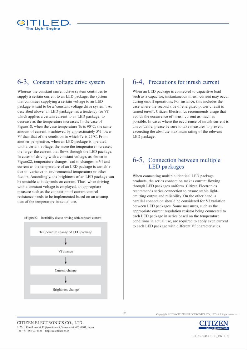
6-3, Constant voltage drive systemWhereas the constant current drive system continues to supply a certain current to an LED package, the system that continues supplying a certain voltage to an LED package is said to be a ‘constant voltage drive system’. As described above, an LED package has a tendency for Vf, which applies a certain current to an LED package, to decrease as the temperature increases. In the case of Figure18, when the case temperature Tc is 90°C, the same amount of current is achieved by approximately 5% lower Vf than that of the condition in which Tc is 25°C. From another perspective, when an LED package is operated with a certain voltage, the more the temperature increases, the larger the current that flows through the LED package. In cases of driving with a constant voltage, as shown in Figure22, temperature changes lead to changes in Vf and current as the temperature of an LED package is unstable due to variance in environmental temperature or other factors. Accordingly, the brightness of an LED package can be unstable as it depends on current. Thus, when driving with a constant voltage is employed, an appropriate measure such as the connection of current control resistance needs to be implemented based on an assump-tion of the temperature in actual use.
6-4, Precautions for inrush currentWhen an LED package is connected to capacitive load such as a capacitor, instantaneous inrush current may occur during on/off operations. For instance, this includes the case where the second side of energized power circuit is turned on/off. Citizen Electronics recommends usage that avoids the occurrence of inrush current as much as possible. In cases where the occurrence of inrush current is unavoidable, please be sure to take measures to prevent exceeding the absolute maximum rating of the relevant LED package.
6-5, Connection between multiple LED packages
When connecting multiple identical LED package products, the series connection makes current flowing through LED packages uniform. Citizen Electronics recommends series connection to ensure stable light-emitting output and reliability. On the other hand, a parallel connection should be considered for Vf variation between LED packages. Some measures, such as the appropriate current regulation resistor being connected to each LED package in series based on the temperature conditions in actual use, are required to apply even current to each LED package with different Vf characteristics.
CITIZEN ELECTRONICS CO., LTD.1-23-1, Kamikurechi, Fujiyoshida-shi, Yamanashi, 403-0001, Japan Tel. +81-555-23-4121 http://ce.citizen.co.jp
■Figure22 Instability due to driving with constant current
Temperature change of LED package
Vf change
Current change
Brightness change
Ref.CE-P2468 03/13_R1(1213)
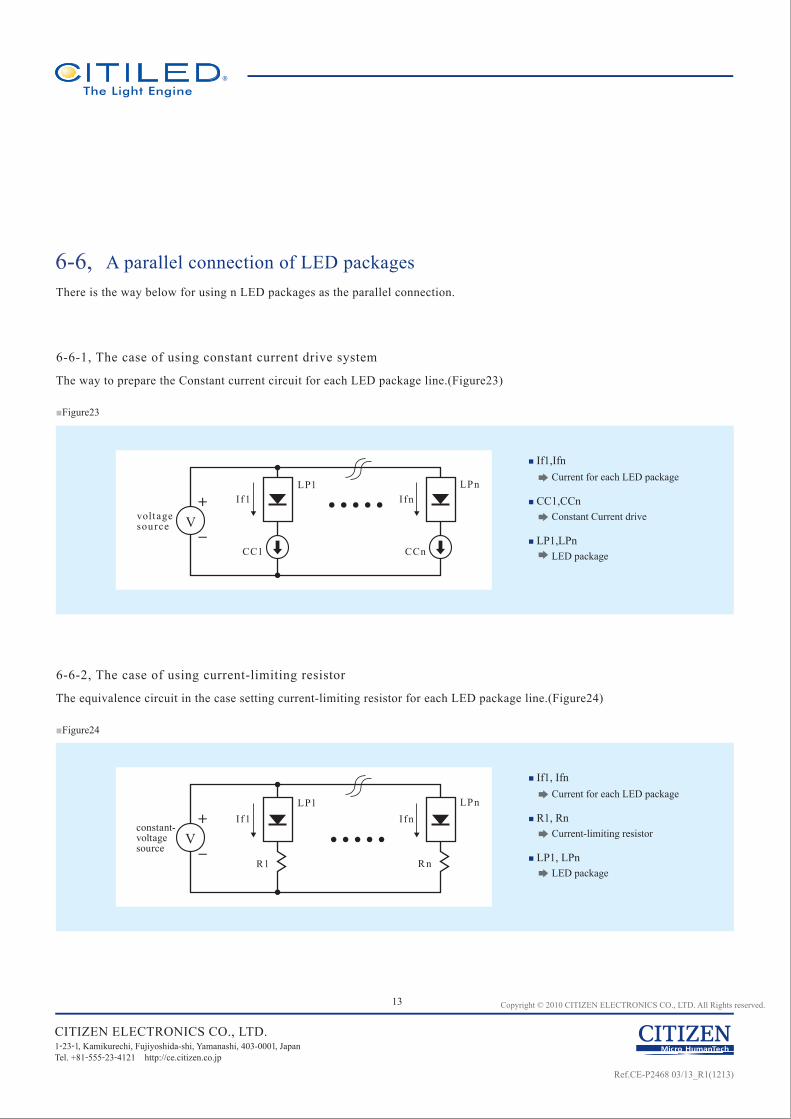
6-6-1, The case of using constant current drive system
■ If1, Ifn Current for each LED package
■ R1, Rn Current-limiting resistor
■ LP1, LPn LED package
13 Copyright © 2010 CITIZEN ELECTRONICS CO., LTD. All Rights reserved.
The way to prepare the Constant current circuit for each LED package line.(Figure23)
CITIZEN ELECTRONICS CO., LTD.1-23-1, Kamikurechi, Fujiyoshida-shi, Yamanashi, 403-0001, Japan Tel. +81-555-23-4121 http://ce.citizen.co.jp
■ If1,Ifn Current for each LED package
■ CC1,CCn Constant Current drive
■ LP1,LPn LED package
voltagesource
If1 IfnLPn
CC1 CCn
LP1
V
constant-voltagesource
If1 IfnLPn
R1 R n
LP1
V
There is the way below for using n LED packages as the parallel connection.
6-6, A parallel connection of LED packages
■Figure23
6-6-2, The case of using current-limiting resistor
The equivalence circuit in the case setting current-limiting resistor for each LED package line.(Figure24)
■Figure24
Ref.CE-P2468 03/13_R1(1213)
14 Copyright © 2010 CITIZEN ELECTRONICS CO., LTD. All Rights reserved.
7,Chemical Incompatibility
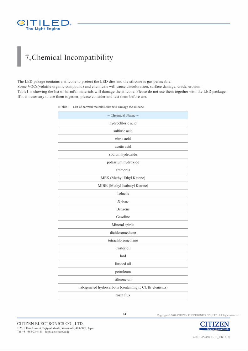
The LED pakage contains a silicone to protect the LED dies and the silicone is gas permeable.Some VOCs(volatile organic compound) and chemicals will cause discoloration, surface damage, crack, erosion.Table1 is showing the list of harmful materials will damage the silicone. Please do not use them together with the LED package. If it is necessary to use them together, please consider and test them before use.
CITIZEN ELECTRONICS CO., LTD.1-23-1, Kamikurechi, Fujiyoshida-shi, Yamanashi, 403-0001, Japan Tel. +81-555-23-4121 http://ce.citizen.co.jp
■Table1 List of harmful materials that will damage the silicone.
~ Chemical Name ~
hydrochloric acid
sulfuric acid
nitric acid
acetic acid
sodium hydroxide
potassium hydroxide
ammonia
MEK (Methyl Ethyl Ketone)
MIBK (Methyl Isobutyl Ketone)
Toluene
Xylene
Benzene
Gasoline
Mineral spirits
dichloromethane
tetrachloromethane
Castor oil
lard
linseed oil
petroleum
silicone oil
halogenated hydrocarbons (containing F, Cl, Br elements)
rosin flux
Ref.CE-P2468 03/13_R1(1213)
15 Copyright © 2010 CITIZEN ELECTRONICS CO., LTD. All Rights reserved.
8,Solutions
The short list below shows some commercially available design resources. Citizen Electronics introduce a variety of solutions (Optical solutions, Thermal solutions, Electrical solutions, Electrical devices, Connectors, Sockets) that may be used to handle and assemble Citizen Electronics LED package approved or qualified suppliers for customers convenience. It is the responsibility of the customer to fully qualify and validate luminaire design components and assembly processes to meet all code and regulatory requirement. Please check the detail at the URL site below. This information contained in URL may be changed without notice.
CITIZEN ELECTRONICS CO., LTD.1-23-1, Kamikurechi, Fujiyoshida-shi, Yamanashi, 403-0001, Japan Tel. +81-555-23-4121 http://ce.citizen.co.jp
Top page of solution information
Optical solutions
Thermal solutions
Electrical solutions
Electronic devices
Connectors
Sockets
http://ce.citizen.co.jp/lighting_led/en/technology/solutions/index.html
Introducing manufacturers who provide lenses, reflectors or holders for our LED packages. http://ce.citizen.co.jp/lighting_led/en/technology/solutions/lens.html
Introducing manufacturers who provide heatsink, thermal interface materials for our LED packages. http://ce.citizen.co.jp/lighting_led/en/technology/solutions/heat.html
Introducing manufacturers who provide power supplies, drivers for our LED packages. http://ce.citizen.co.jp/lighting_led/en/technology/solutions/power.html
Introducing manufacturers who provide electronic devices for our LED packages. http://ce.citizen.co.jp/lighting_led/en/technology/solutions/device.html
Introducing manufacturers who provide connectors for our LED packages. http://ce.citizen.co.jp/lighting_led/en/technology/solutions/connector.html
Introducing manufacturers who provide Socket for our LED packages. http://ce.citizen.co.jp/lighting_led/en/technology/solutions/socket.html
URL
URL
URL
URL
URL
URL
URL
Ref.CE-P2468 03/13_R1(1213)
Information contained in this document such as sentences, photographs and images is subject to copyright, and is protected by law. Unless it is for “duplication for private use” or “quotation” under copyright law, any duplication or diversion of this information without permission of CITIZEN ELECTRONICS CO., LTD. is prohibited by law.
CITIZEN ELECTRONICS CO., LTD. shall not be liable for any disadvantages or
damages resulting from the use of technical information or data included in this
document or the impossibility of download and use, responsibility for the cause of
lawsuit or any other damages or losses.
This technical information or data shall be provided ‘as is’ to users and CITIZEN
ELECTRONICS CO., LTD. does not guarantee the absence of error or other defects in
this technical information or data, conformance of this technical information or data to
specific purpose, this technical information or data or its use will not infringe the
rights of users or third parties or any other content.
CITIZEN ELECTRONICS CO., LTD. reserves the right to make changes to technical
information or data without notification.
●
●
●
CITIZEN ELECTRONICS CO., LTD.
1-23-1, Kamikurechi, Fujiyoshida-shi, Yamanashi, 403-0001, Japan Tel. +81-555-23-4121 http://ce.citizen.co.jp
Requests / [email protected]
Website for LEDs for lightinghttp://ce.citizen.co.jp/lighting_led/jp/
Ref.CE-P2468 03/13_R1(1213)


![LC013D - Samsung US€¦ · LC013D . High efficacy COB LED package . ... 1505 - D1 . 1505 : 1580 - Notes: ... [ mA ] Tc [ ℃ ] Derating Curve . 12](https://img.pdfslide.net/doc/110x75/5ad0db687f8b9ad24f8e276b/lc013d-samsung-us-lc013d-high-efficacy-cob-led-package-1505-d1-1505.jpg)
![CITILED COB+ Series · Ref.CE-P2987 02/15 [5] 1. Introduction 1-1. Product Description G 1-2. Features COB+ is the new type of LED package AC-Driver embedded in the standard COB(Chip](https://img.pdfslide.net/doc/110x75/60ccff13a6b2a15cd151099d/citiled-cob-series-refce-p2987-0215-5-1-introduction-1-1-product-description.jpg)