Embed Size (px)
Citation preview

Instruction manualInstruction manualOperating & MaintenanceOperating & Maintenance
4812160101_B.pdf4812160101_B.pdf
Vibratory rollerVibratory rollerCA3500DCOCA3500DCOCA3600DCOCA3600DCOCA5000DCOCA5000DCOCA6000DCOCA6000DCO
EngineEngineCummins QSB 4.5 (IIIA/T3) / (IIIB/T4i)Cummins QSB 4.5 (IIIA/T3) / (IIIB/T4i)
Deutz TCD 2012 L6 (IIIA/T3) / TCD 6.1 L6 (IIIB/T4i) Deutz TCD 2012 L6 (IIIA/T3) / TCD 6.1 L6 (IIIB/T4i)
Serial numberSerial number10000145x0A010028 -10000145x0A010028 -10000146x0A00xxxx -10000146x0A00xxxx -10000147x0A00xxxx -10000147x0A00xxxx -10000148x0A00xxxx -10000148x0A00xxxx -10000133xFA016993 -10000133xFA016993 -10000129x0A008983 -10000129x0A008983 -10000135x0A00xxxx -10000135x0A00xxxx -10000131x0A00xxxx -10000131x0A00xxxx -
Translation of original instructionTranslation of original instruction
Reservation for changesReservation for changesPrinted in SwedenPrinted in Sweden


2000h-Maintenance
4812160101_B.pdf2015-11-05
Table of Contents
Introduction .............................................................................................................................. 1
The machine ............................................................................................... 1
Intended use ............................................................................................... 1
Warning symbols......................................................................................... 1
Safety information ....................................................................................... 1
General ....................................................................................................... 2
CE marking and Declaration of conformity.................................................. 3
Safety - General instructions.................................................................................................... 5
Safety - when operating ........................................................................................................... 7
Driving near edges ...................................................................................... 7
Slopes ......................................................................................................... 8
Safety (Optional) ...................................................................................................................... 9
Air conditioning............................................................................................ 9
Special instructions ................................................................................................................ 11
Standard lubricants and other recommended oils and fluids .................... 11
Higher ambient temperatures, above +40°C (104°F)................................ 11
Temperatures............................................................................................ 11
High pressure cleaning ............................................................................. 11
Fire fighting ............................................................................................... 12
Roll Over Protective Structure (ROPS), ROPS approved cab .................. 12
Welding ..................................................................................................... 12
Battery handling ........................................................................................ 12
Jump starting (24V)................................................................................... 13
Technical specifications ......................................................................................................... 15
Vibrations - Operator station ..................................................................... 15
Noise level................................................................................................. 15
Electrical system ....................................................................................... 15
Dimensions, side view............................................................................... 16
Dimensions, top view ................................................................................ 17
Weights and volumes................................................................................ 18

2000h-Maintenance
4812160101_B.pdf 2015-11-05
Working capacity....................................................................................... 18
General ..................................................................................................... 20
Liquid-filled tyres (Ballasted tyres).............................................. 21
Hydraulic system....................................................................................... 21
Automatic Climate Control (ACC) (Optional)............................................. 21
Tightening torque ...................................................................................... 22
Machine description ............................................................................................................... 23
Diesel engine, Cummins ........................................................................... 23
Diesel engine, Deutz ................................................................................. 23
Electrical system ....................................................................................... 23
Propulsion system/Transmission .............................................................. 23
Brake system ............................................................................................ 24
Steering system ........................................................................................ 24
Vibration system........................................................................................ 24
Cab............................................................................................................ 24
FOPS and ROPS ...................................................................................... 24
Identification ............................................................................................................ 25
Product and component plates ................................................................. 25
Product identification number on the frame .............................................. 25
Machine plate............................................................................................ 26
Explanation of 17PIN serial number.......................................................... 26
Engine plates ............................................................................................ 27
Decals...................................................................................................................... 28
Location - decals ....................................................................................... 28
Safety decals............................................................................................. 29
Info decals................................................................................................. 31
Instruments/Controls ............................................................................................... 32
Control panel and controls ........................................................................ 32
Function descriptions ................................................................................ 33
Warning indication - membrane panel (Keypad)....................................... 35
2000h-Maintenance
4812160101_B.pdf2015-11-05
Display explanations ................................................................................. 36
Machine alarm........................................................................................... 39
Dynapac Sub System (DSS)..................................................................... 40
"MAIN MENU" ........................................................................................... 41
"USER SETTINGS" .................................................................... 41
"SERVICE MENU"...................................................................... 42
"ABOUT"..................................................................................... 43
"MACHINE SETTINGS".............................................................. 43
Operator help when starting...................................................................... 44
Operator help Workmode.......................................................................... 44
Display when activating choice via the button set..................................... 45
DCO view and status .................................................................. 45
Error messages (DCO) ............................................................... 46
Instruments and controls, cab ................................................................... 47
Function description of instruments and controls in the cab ..................... 48
Using the cab controls............................................................................... 49
Defroster ..................................................................................... 49
Heat ............................................................................................ 49
AC/ACC ...................................................................................... 49
ACC - Control panel .................................................................................. 50
Main display screen .................................................................................. 50
ACC - Operation menus............................................................................ 50
Electrical system...................................................................................................... 52
Fuses in the main switchbox (Cummins) .................................................. 53
Fuses at master switch (Cummins)........................................................... 53
Fuse box at master switch (Cummins)...................................................... 54
Fuses in the main switchbox (Deutz) ........................................................ 54
Fuses at master switch (Deutz)................................................................. 55
Fuse box at master switch (Deutz)............................................................ 56
Fuses in cab.............................................................................................. 56

2000h-Maintenance
4812160101_B.pdf 2015-11-05
Operation ............................................................................................................................... 57
Before starting ......................................................................................................... 57
Master switch - Switching on..................................................................... 57
Operator's seat - Adjustment..................................................................... 57
Belt reminder............................................................................................. 58
Operator's seat, comfort - Adjustments..................................................... 58
Control panel, adjustments ....................................................................... 59
Parking brake ............................................................................................ 59
Display - Control........................................................................................ 60
Interlock..................................................................................................... 61
Operator position....................................................................................... 61
View .......................................................................................................... 62
Starting .................................................................................................................... 63
Starting the engine .................................................................................... 63
Driving ..................................................................................................................... 64
Operating the roller ................................................................................... 64
Machine with TC (Anti-Spin) ....................................................... 64
Slopes (TC (Anti-Spin))............................................................... 65
Interlock/Emergency stop/Parking brake - Check ..................................... 66
Burnout of DPF filter - (IIIB/T4i)................................................................. 67
DPF displays ............................................................................................. 67
Dynapac Compaction Meter (DCM) including Active Bouncing Control(ABC) - Optional........................................................................................ 69
Setting limit................................................................................................ 69
Operation CMV ......................................................................................... 71
Vibration .................................................................................................................. 71
Different operating modes......................................................................... 72
Advice when using DCO ........................................................................... 74
Braking .................................................................................................................... 75
Normal braking.......................................................................................... 75

2000h-Maintenance
4812160101_B.pdf2015-11-05
Emergency braking ................................................................................... 75
Switching off.............................................................................................. 76
Parking .................................................................................................................... 76
Chocking the drums .................................................................................. 76
Master switch ............................................................................................ 77
Long-term parking.................................................................................................................. 79
Engine ....................................................................................................... 79
Battery....................................................................................................... 79
Air cleaner, exhaust pipe........................................................................... 79
Fuel tank ................................................................................................... 79
Hydraulic reservoir .................................................................................... 79
Tires (All-weather)..................................................................................... 79
Hoods, tarpaulin ........................................................................................ 80
Miscellaneous ........................................................................................................................ 81
Lifting ....................................................................................................................... 81
Locking the articulation ............................................................................. 81
Lifting the roller.......................................................................................... 82
Lifting the roller with jack:.......................................................................... 82
Unlocking the articulation .......................................................................... 83
Towing/Recovering.................................................................................................. 83
Short distance towing with the engine running.......................................... 84
Short distance towing when the engine is inoperative. ............................. 85
Towing the roller........................................................................................ 86
Transport ................................................................................................................. 86
Securing CA1500-CA4600 for loading ...................................................... 87
Securing CA5000 for loading .................................................................... 89
Securing CA5500/6000/6500 for loading .................................................. 91
Operating instructions - Summary ......................................................................................... 93
Preventive maintenance ........................................................................................................ 95
Acceptance and delivery inspection.......................................................... 95

2000h-Maintenance
4812160101_B.pdf 2015-11-05
Warranty.................................................................................................... 95
Maintenance - Lubricants and symbols ................................................................................. 97
Maintenance symbols ............................................................................... 98
Maintenance - Maintenance schedule ................................................................................... 99
Service and maintenance points ............................................................... 99
General ..................................................................................................... 99
Periodic service (service message) - Optional........................................ 100
Every 10 hours of operation (Daily)......................................................... 101
After the FIRST 50 hours of operation .................................................... 101
Every 50 hours of operation (Weekly)..................................................... 101
Every 250 / 750 / 1250 / 1750 hours of operation ................................... 102
Every 500 / 1500 hours of operation ....................................................... 102
Every 1000 hours of operation ................................................................ 103
Every 2000 hours of operation ................................................................ 104
Every other year...................................................................................... 105
Maintenance, 10h ................................................................................................................ 107
Scrapers - Check, adjustment................................................................. 107
Air circulation - Check ............................................................................. 108
Coolant level - Check .............................................................................. 108
Diesel engine Check oil level ................................................................. 109
Fuel tank - Filling..................................................................................... 109
Hydraulic reservoir - Check fluid level..................................................... 110
Maintenance - 50h ............................................................................................................... 111
Hydraulic filter - Replacement ................................................................. 111
Tires - Air pressure - Wheel nuts - Tightening ........................................ 113
Drum gearbox - Oil change ..................................................................... 113
Steering hitch - Tightening ...................................................................... 114
Air cleaner- Check hoses and connections .............................................................. 115
Drum - Oil change ................................................................................... 115

2000h-Maintenance
4812160101_B.pdf2015-11-05
Gearbox - Oil change .............................................................................. 117
Maintenance - 250 / 750 / 1250 / 1750h .............................................................................. 119
Rear axle differential - Check oil level..................................................... 119
Rear axle planetary gears - Check oil level............................................. 120
Drum - Checking the oil level .................................................................. 120
Gearbox - Checking the oil level ............................................................. 121
Drum gearbox - Checking the oil level .................................................... 122
Radiator - Check/Cleaning ...................................................................... 122
Rubber elements and fastening screws - Check..................................... 123
Battery- Check condition .................................................................................... 123
Air conditioning (Optional)- Inspection.............................................................................................. 124
Automatic Climate Control (Optional) - Inspection .................................. 124
Maintenance - 500 / 1500h .................................................................................................. 125
Air cleanerChecking - Change the main air filter...................................................... 125
Backup filter - Change............................................................................. 126
Air cleaner- Cleaning................................................................................................ 126
Rear axle differential - Check oil level..................................................... 127
Rear axle planetary gears - Check oil level............................................. 127
Drum - Checking the oil level .................................................................. 128
Gearbox - Oil change .............................................................................. 129
Drum gearbox - Checking the oil level .................................................... 129
Radiator - Check/Cleaning ...................................................................... 130
Fuel pre-filter - Replacement................................................................... 130
Replacing the fuel filter............................................................................ 131
Diesel engine - Oil and Filter change ...................................................... 132
Hood, hinges - Lubrication ...................................................................... 132
Seat bearing - Lubrication ....................................................................... 133

2000h-Maintenance
4812160101_B.pdf 2015-11-05
Maintenance - 1000h ........................................................................................................... 135
Hydraulic filter - Replacement ................................................................. 135
Air cleanerChecking - Change the main air filter...................................................... 136
Backup filter - Change............................................................................. 137
Air cleaner- Cleaning................................................................................................ 138
Rear axle differential - Oil change........................................................... 139
Rear axle planetary gear - Oil change .................................................... 139
Drum - Checking the oil level .................................................................. 140
Gearbox - Oil change .............................................................................. 141
Drum gearbox - Oil change ..................................................................... 141
Radiator - Check/Cleaning ...................................................................... 142
Fuel pre-filter - Replacement................................................................... 142
Replacing the fuel filter............................................................................ 143
Diesel engine - Oil and Filter change ...................................................... 144
Seat bearing - Lubrication ....................................................................... 145
Hydraulic reservoir - Draining.................................................................. 145
Fuel tank - Draining (Optional) ................................................................ 146
Air conditioning (Optional)Fresh air filter - Change .......................................................................... 146
Steering hitch - Tightening ...................................................................... 147
Maintenance - 2000h ........................................................................................................... 149
Hydraulic reservoir - Oil change.............................................................. 149
Hydraulic filter - Replacement ................................................................. 150
Drum gearbox - Oil change ..................................................................... 151
Air cleanerChecking - Change the main air filter...................................................... 151
Backup filter - Change............................................................................. 152
Air cleaner- Cleaning................................................................................................ 152
Rear axle planetary gear - Oil change .................................................... 153

2000h-Maintenance
4812160101_B.pdf2015-11-05
Rear axle differential - Oil change........................................................... 154
Drum - Oil change ................................................................................... 154
Gearbox - Oil change .............................................................................. 156
Radiator - Check/Cleaning ...................................................................... 156
Fuel pre-filter - Replacement................................................................... 157
Replacing the fuel filter............................................................................ 157
Diesel engine - Oil and Filter change ...................................................... 158
Seat bearing - Lubrication ....................................................................... 159
Hydraulic reservoir - Draining.................................................................. 159
Fuel tank - Draining (Optional) ................................................................ 160
Air conditioning (Optional)Fresh air filter - Change .......................................................................... 160
Automatic Climate Control (Optional)- Overhaul ............................................................................................... 161
Drying filter - Check................................................................................. 161
Steering hitch - Tightening ...................................................................... 162

2000h-Maintenance
4812160101_B.pdf 2015-11-05

Introduction
4812160101_B.pdf2015-11-05
Introduction
The machineCA3500/3600DCO are models of Dynapac'smedium-heavy earth compaction rollers. The machineis a D (smooth drum) variant with optimizedcompaction system "Compaction Optimizer" (CO).
CA5000/6000DCO are models of Dynapac's heavyearth compaction rollers. The machine is a D (smoothdrum) variant with optimized compaction system"Compaction Optimizer" (CO).
Intended useAll types of base courses and subbase courses can becompacted.
Dynapac Compaction Optimizer (DCO) optimizes thecompaction work by continuously adjusting thecompaction effect to the composition of the surface. Itcan be used together with another roller accessory,the Dynapac Compaction Analyzer (DCA), whichenables the compaction results to be documented andstored.
The cab and safety-related accessories are describedin this manual. Other accessories, such as tachograph"and "Analyzer" (DCA) are described in separateinstructions.
Warning symbols
WARNING ! Marks a danger or a hazardousprocedure that can result in life threatening orserious injury if the warning is ignored.
WARNING ! Marks a danger or a hazardousprocedure that can result in life threatening orserious injury if the warning is ignored.
CAUTION ! Marks a danger or hazardousprocedure that can result in damage to themachine or property if the warning is ignored.
CAUTION ! Marks a danger or hazardousprocedure that can result in damage to themachine or property if the warning is ignored.
Safety information
It is recommended to at least train operators inhandling and daily maintenance of the machinein accordance with the instruction manual.
It is recommended to at least train operators inhandling and daily maintenance of the machinein accordance with the instruction manual.Passengers are not allowed on the machine, andyou must sit in the seat when operating themachine.
Passengers are not allowed on the machine, andyou must sit in the seat when operating themachine.
1

Introduction
4812160101_B.pdf 2015-11-05
The safety manual supplied with the machinemust be read by all roller operators. Alwaysfollow the safety instructions. Do not removethe manual from the machine.
The safety manual supplied with the machinemust be read by all roller operators. Alwaysfollow the safety instructions. Do not removethe manual from the machine.
We recommend that the operator reads thesafety instructions in this manual carefully.Always follow the safety instructions. Ensurethat this manual is always easily accessible.
We recommend that the operator reads thesafety instructions in this manual carefully.Always follow the safety instructions. Ensurethat this manual is always easily accessible.
Read the entire manual before starting themachine and before carrying out anymaintenance.
Read the entire manual before starting themachine and before carrying out anymaintenance.
Ensure good ventilation (extraction of air by fan)where the engine is run indoors.Ensure good ventilation (extraction of air by fan)where the engine is run indoors.
CALIFORNIA
Proposition 65 Warning
Diesel engine exhaust and some of its constituents areknown to the State of California to cause cancer, birthdefects, and other reproductive harm.
GeneralThis manual contains instructions for machineoperation and maintenance.
The machine must be correctly maintained formaximal performance.
The machine should be kept clean so that anyleakages, loose bolts and loose connections arediscovered at as early a point in time as possible.
Inspect the machine every day, before starting.Inspect the entire machine so that any leakages orother faults are detected.
Check the ground under the machine. Leakages aremore easily detected on the ground than on themachine itself.
THINK ENVIRONMENT ! Do not release oil,fuel and other environmentally hazardoussubstances into the environment. Always sendused filters, drain oil and fuel remnants toenvironmentally correct disposal.
THINK ENVIRONMENT ! Do not release oil,fuel and other environmentally hazardoussubstances into the environment. Always sendused filters, drain oil and fuel remnants toenvironmentally correct disposal.
2

Introduction
4812160101_B.pdf2015-11-05
This manual contains instructions for periodicmaintenance normally carried out by the operator.
Additional instructions for the engine can befound in the manufactuer's engine manual.Additional instructions for the engine can befound in the manufactuer's engine manual.
If the roller is equipped with a Step IIIB/4i dieselengine and a particle filter (DPF-filter), the enginewill automatically burn out soot. See more underthe sections "Machine description" and"Operation".
If the roller is equipped with a Step IIIB/4i dieselengine and a particle filter (DPF-filter), the enginewill automatically burn out soot. See more underthe sections "Machine description" and"Operation".
CE marking and Declaration of conformity(Applies to machines marketed in EU/EEC)
This machine is CE marked. This shows that ondelivery it complies with the basic health and safetydirectives applicable for the machine in accordancewith machinery directive 2006/42/EC and that it alsocomplies with other directives applicable for thismachine.
A "Declaration of conformity" is supplied with thismachine, which specifies the applicable directives andsupplements, as well as the harmonized standardsand other regulations that are applied.
3

Introduction
4812160101_B.pdf 2015-11-054

Safety - General instructions
4812160101_B.pdf2015-11-05
Safety - General instructions
(Also read the safety manual)
1. The operator must be familiar with the contents of the OPERATION sectionbefore starting the roller.
1. The operator must be familiar with the contents of the OPERATION sectionbefore starting the roller.
2. Ensure that all instructions in the MAINTENANCE section are followed.2. Ensure that all instructions in the MAINTENANCE section are followed.
3. Only trained and/or experienced operators are to operate the roller.Passengers are not permitted on the roller. Remain seated at all times whenoperating the roller.
3. Only trained and/or experienced operators are to operate the roller.Passengers are not permitted on the roller. Remain seated at all times whenoperating the roller.
4. Never use the roller if it is in need of adjustment or repair.4. Never use the roller if it is in need of adjustment or repair.
5. Only mount and dismount the roller when it is stationary. Use the intendedgrips and rails. Always use the three-point grip (both feet and one hand, orone foot and both hands) when mounting or dismounting the machine.Never jump down from the machine.
5. Only mount and dismount the roller when it is stationary. Use the intendedgrips and rails. Always use the three-point grip (both feet and one hand, orone foot and both hands) when mounting or dismounting the machine.Never jump down from the machine.
6. The ROPS (Roll Over Protective Structure) should always be used when themachine is operated on unsafe ground.
6. The ROPS (Roll Over Protective Structure) should always be used when themachine is operated on unsafe ground.
7. Drive slowly in sharp bends.7. Drive slowly in sharp bends.
8. Avoid driving across slopes. Drive straight up or straight down the slope.8. Avoid driving across slopes. Drive straight up or straight down the slope.
9. When driving close to edges, ditches or holes, make sure that at least 2/3 ofthe drum width is on previously compacted material (solid surface).
9. When driving close to edges, ditches or holes, make sure that at least 2/3 ofthe drum width is on previously compacted material (solid surface).
10. Make sure that there are no obstacles in the direction of travel, on theground, in front of or behind the roller, or overhead.
10. Make sure that there are no obstacles in the direction of travel, on theground, in front of or behind the roller, or overhead.
11. Drive particularly carefully on uneven ground.11. Drive particularly carefully on uneven ground.
12. Use the safety equipment provided. The seat belt must be worn on machinesfitted with ROPS/ROPS-cab.
12. Use the safety equipment provided. The seat belt must be worn on machinesfitted with ROPS/ROPS-cab.
13. Keep the roller clean. Clean any dirt or grease that accumulates on theoperator platform immediately. Keep all signs and decals clean and legible.
13. Keep the roller clean. Clean any dirt or grease that accumulates on theoperator platform immediately. Keep all signs and decals clean and legible.
14. Safety measures before refueling:- Stop the engine- Do not smoke.- No naked flames in the vicinity of the roller.- Earth the filling equipment nozzle to the tank opening to avoid sparks.
14. Safety measures before refueling:- Stop the engine- Do not smoke.- No naked flames in the vicinity of the roller.- Earth the filling equipment nozzle to the tank opening to avoid sparks.
15. Before repairs or service:- Chock the drums/wheels and under the strike-off blade.- Lock the articulation if necessary
15. Before repairs or service:- Chock the drums/wheels and under the strike-off blade.- Lock the articulation if necessary
5

Safety - General instructions
4812160101_B.pdf 2015-11-05
16. Hearing protection is recommended if the noise level exceeds 85 dB(A). Thenoise level can vary depending on the equipment on the machine and thesurface the machine is being used on.
16. Hearing protection is recommended if the noise level exceeds 85 dB(A). Thenoise level can vary depending on the equipment on the machine and thesurface the machine is being used on.
17. Do not make any changes or modifications to the roller that could affectsafety. Changes are only to be made after written approval has been givenby Dynapac.
17. Do not make any changes or modifications to the roller that could affectsafety. Changes are only to be made after written approval has been givenby Dynapac.
18. Avoid using the roller before the hydraulic fluid has reached its normalworking temperature. Braking distances can be longer than normal when thefluid is cold. See instructions in the STOP section.
18. Avoid using the roller before the hydraulic fluid has reached its normalworking temperature. Braking distances can be longer than normal when thefluid is cold. See instructions in the STOP section.
19. For your own protection always wear:- helmet- working boots with steel toecaps- ear protectors- reflecting clothing/high visibility jacket- working gloves
19. For your own protection always wear:- helmet- working boots with steel toecaps- ear protectors- reflecting clothing/high visibility jacket- working gloves
6

Safety - when operating
4812160101_B.pdf2015-11-05
Safety - when operating
Prevent persons from entering or remaining inthe danger area, i.e. a distance of at least 7 m(23 ft) in all directions from operating machines.
Prevent persons from entering or remaining inthe danger area, i.e. a distance of at least 7 m(23 ft) in all directions from operating machines.The operator may allow a person to remain inthe danger area, but should then observecaution and operate the machine only when theperson is visible or has given clear indicationsof where he or she is.
The operator may allow a person to remain inthe danger area, but should then observecaution and operate the machine only when theperson is visible or has given clear indicationsof where he or she is.
Driving near edges
Fig. Position of drum when driving nearan edge
Minimum 2/3
When driving near an edge, minimum 2/3 of the drumwidth must be on solid ground.
Keep in mind that the machine's center of gravitymoves outwards when steering. For example, thecenter of gravity moves to the right when yousteer to the left.
Keep in mind that the machine's center of gravitymoves outwards when steering. For example, thecenter of gravity moves to the right when yousteer to the left.
7
Safety - when operating
4812160101_B.pdf 2015-11-05
Slopes
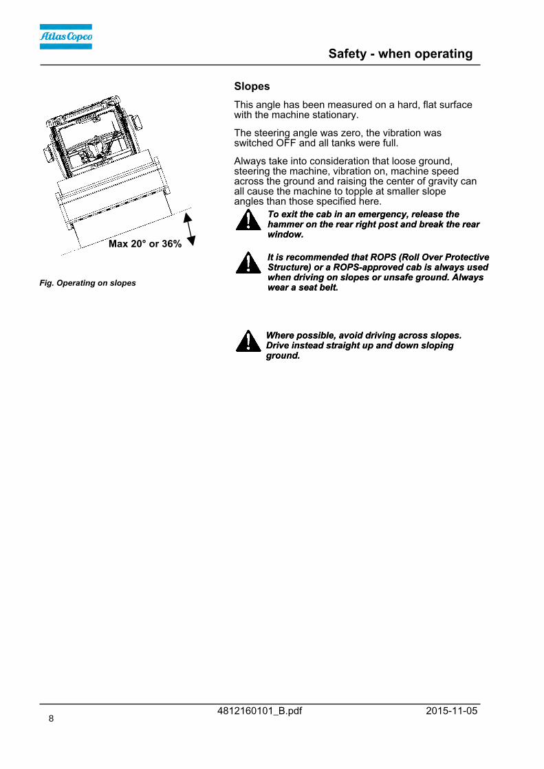
Fig. Operating on slopes
Max 20° or 36%
This angle has been measured on a hard, flat surfacewith the machine stationary.
The steering angle was zero, the vibration wasswitched OFF and all tanks were full.
Always take into consideration that loose ground,steering the machine, vibration on, machine speedacross the ground and raising the center of gravity canall cause the machine to topple at smaller slopeangles than those specified here.
To exit the cab in an emergency, release thehammer on the rear right post and break the rearwindow.
To exit the cab in an emergency, release thehammer on the rear right post and break the rearwindow.
It is recommended that ROPS (Roll Over ProtectiveStructure) or a ROPS-approved cab is always usedwhen driving on slopes or unsafe ground. Alwayswear a seat belt.
It is recommended that ROPS (Roll Over ProtectiveStructure) or a ROPS-approved cab is always usedwhen driving on slopes or unsafe ground. Alwayswear a seat belt.
Where possible, avoid driving across slopes.Drive instead straight up and down slopingground.
Where possible, avoid driving across slopes.Drive instead straight up and down slopingground.
8
Safety (Optional)
4812160101_B.pdf2015-11-05
Safety (Optional)
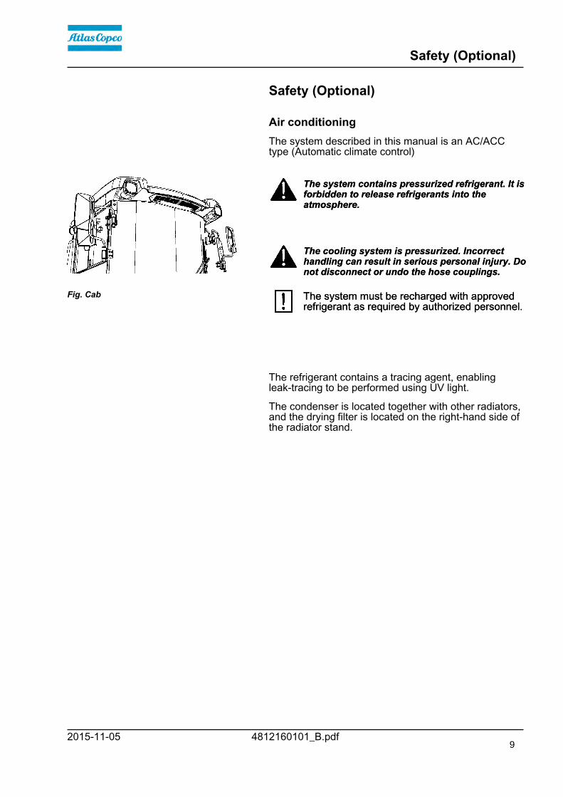
Air conditioningThe system described in this manual is an AC/ACCtype (Automatic climate control)
Fig. Cab
The system contains pressurized refrigerant. It isforbidden to release refrigerants into theatmosphere.
The system contains pressurized refrigerant. It isforbidden to release refrigerants into theatmosphere.
The cooling system is pressurized. Incorrecthandling can result in serious personal injury. Donot disconnect or undo the hose couplings.
The cooling system is pressurized. Incorrecthandling can result in serious personal injury. Donot disconnect or undo the hose couplings.
The system must be recharged with approvedrefrigerant as required by authorized personnel.The system must be recharged with approvedrefrigerant as required by authorized personnel.
The refrigerant contains a tracing agent, enablingleak-tracing to be performed using UV light.
The condenser is located together with other radiators,and the drying filter is located on the right-hand side ofthe radiator stand.
9

Safety (Optional)
4812160101_B.pdf 2015-11-0510

Special instructions
4812160101_B.pdf2015-11-05
Special instructions
Standard lubricants and other recommendedoils and fluidsBefore leaving the factory, the systems andcomponents are filled with the oils and fluids specifiedin the lubricant specification. These are suitable forambient temperatures in the range -15°C to +40°C(5°F - 105°F).
The maximum temperature for biologicalhydraulic fluid is +35°C (95°F).The maximum temperature for biologicalhydraulic fluid is +35°C (95°F).
Higher ambient temperatures, above +40°C(104°F)For operation of the machine at higher ambienttemperatures, however maximum +50°C (122°F), thefollowing recommendations apply:
The diesel engine and hydraulic system can be run atthis temperature using normal oil, but in othercomponents that use transmission oil, Shell Spirax S3AX85W/140, API GL-5 or equivalent must be used.
TemperaturesThe temperature limits apply to standard versions ofrollers.
Rollers equipped with additional equipment, such asnoise suppression, may need to be more carefullymonitored in the higher temperature ranges.
High pressure cleaningDo not spray directly onto electrical components.
Do not use a high-pressure water jet on theinstrument panel/display.Do not use a high-pressure water jet on theinstrument panel/display.
Detergent that can destroy electrical parts, orwhich is conductive, must not be used.Detergent that can destroy electrical parts, orwhich is conductive, must not be used.
In certain cases there is an electrical control leverand associated electronic control unit (ECU) inthe engine compartment, which must not bewashed with a high-pressure jet or with any waterat all. It is sufficient to wipe these off.The same applies to the engine electronic controlunit (engine ECU).
In certain cases there is an electrical control leverand associated electronic control unit (ECU) inthe engine compartment, which must not bewashed with a high-pressure jet or with any waterat all. It is sufficient to wipe these off.The same applies to the engine electronic controlunit (engine ECU).
Place a plastic bag over the fuel filler cap and secure
11

Special instructions
4812160101_B.pdf 2015-11-05
with a rubber band. This is to avoid high pressurewater entering the vent hole in the filler cap. This couldcause malfunctions, such as the blocking of filters.
Place a plastic bag over the exhaust pipe and securewith a rubber band to avoid water in the muffler.
Never aim the water jet directly at the fuel tankcap. This is particularly important when using ahigh-pressure cleaner.
Never aim the water jet directly at the fuel tankcap. This is particularly important when using ahigh-pressure cleaner.
Fire fightingIf the machine catches fire, use an ABC-class powderfire extinguisher.
A BE-class carbon dioxide fire extinguisher can alsobe used.
Roll Over Protective Structure (ROPS), ROPSapproved cab
If the machine is fitted with a Roll OverProtective Structure (ROPS, or ROPS approvedcab) never carry out any welding or drilling inthe structure or cab.
If the machine is fitted with a Roll OverProtective Structure (ROPS, or ROPS approvedcab) never carry out any welding or drilling inthe structure or cab.
Never attempt to repair a damaged ROPSstructure or cab. These must be replaced withnew ROPS structure or cabs.
Never attempt to repair a damaged ROPSstructure or cab. These must be replaced withnew ROPS structure or cabs.
WeldingWhen carrying out welding on the machine, thebattery must be disconnected and theelectronics disconnected from the electricalsystem.
When carrying out welding on the machine, thebattery must be disconnected and theelectronics disconnected from the electricalsystem.
If possible, remove the part(s) to be weldedfrom the machine.If possible, remove the part(s) to be weldedfrom the machine.
Battery handling
When removing batteries, always disconnect thenegative cable first.When removing batteries, always disconnect thenegative cable first.
When fitting batteries, always connect thepositive cable first.When fitting batteries, always connect thepositive cable first.
12

Special instructions
4812160101_B.pdf2015-11-05
Dispose of old batteries in an environmentallyfriendly way. Batteries contain toxic lead.Dispose of old batteries in an environmentallyfriendly way. Batteries contain toxic lead.
Do not use a quick-charger for charging thebattery. This may shorten battery life.Do not use a quick-charger for charging thebattery. This may shorten battery life.
Jump starting (24V)
Do not connect the negative cable to thenegative terminal on the dead battery. A sparkcan ignite the oxy-hydrogen gas formedaround the battery.
Do not connect the negative cable to thenegative terminal on the dead battery. A sparkcan ignite the oxy-hydrogen gas formedaround the battery.
Check that the battery used for jump startinghas the same voltage as the dead battery.Check that the battery used for jump startinghas the same voltage as the dead battery.
24V
12V
12V
Fig. Jump starting
12
3
4
Turn the ignition and all power consuming equipmentoff. Switch off the engine on the machine which isproviding jump start power.
Jump leads must have 24V.
First connect the jump start battery's positive terminal(1) to the flat battery's positive terminal (2).Thenconnect the jump start battery's negative terminal (3)to, for example, a bolt (4) or the lifjting eye on themachine with the flat battery.
Start the engine on the power providing machine. Let itrun for a while. Now try to start the other machine.Disconnect the cables in the reverse order.
13

Special instructions
4812160101_B.pdf 2015-11-0514

Technical specifications
4812160101_B.pdf2015-11-05
Technical specifications
Vibrations - Operator station(ISO 2631)
The vibration levels are measured in accordance with the operational cycle described inEU directive 2000/14/EC on machines equipped for the EU market, with vibration switchedon, on soft polymer material and with the operator’s seat in the transport position.
The vibration levels are measured in accordance with the operational cycle described inEU directive 2000/14/EC on machines equipped for the EU market, with vibration switchedon, on soft polymer material and with the operator’s seat in the transport position.Measured whole-body vibrations are below the action value of 0.5 m/s² as specified in Directive2002/44/EC. (Limit is 1.15 m/s²)Measured whole-body vibrations are below the action value of 0.5 m/s² as specified in Directive2002/44/EC. (Limit is 1.15 m/s²)Measured hand/arm vibrations also were below the action level of 2.5 m/s² specified in the samedirective. (Limit is 5 m/s²)Measured hand/arm vibrations also were below the action level of 2.5 m/s² specified in the samedirective. (Limit is 5 m/s²)
Noise level
The noise level is measured in accordance with the operational cycle described in EUdirective 2000/14/EC on machines equipped for the EU market, on soft polymer materialwith vibration switched on and the operator's seat in the transport position.
The noise level is measured in accordance with the operational cycle described in EUdirective 2000/14/EC on machines equipped for the EU market, on soft polymer materialwith vibration switched on and the operator's seat in the transport position.
Guaranteed sound power level, LwA 103 dB (A)Guaranteed sound power level, LwA 103 dB (A)
Sound pressure level at the driver's ear (platform/ROPS), LpA XX dB (A)Sound pressure level at the driver's ear (platform/ROPS), LpA XX dB (A)
Sound pressure level at the operator's ear (cab), LpA 72 ±3 dB (A)Sound pressure level at the operator's ear (cab), LpA 72 ±3 dB (A)
Electrical systemMachines are EMC tested in accordance with EN13309:2000 'Construction machinery'
15

Technical specifications
4812160101_B.pdf 2015-11-05
Dimensions, side view
Dimensions mm inDimensions mm inA Wheelbase, drum and wheelA Wheelbase, drum and wheel
CA3500, CA3600 2990 118CA3500, CA3600 2990 118
CA5000, CA6000 3100 122CA5000, CA6000 3100 122
L Length, standard equipped rollerL Length, standard equipped roller
CA3500, CA3600 6000 236CA3500, CA3600 6000 236
CA5000, CA6000 6240 246CA5000, CA6000 6240 246
H1 Height, with ROPS/cabH1 Height, with ROPS/cab
CA3500, CA3600 2870 113CA3500, CA3600 2870 113
CA5000, CA6000 2890 114CA5000, CA6000 2890 114
H2 Height, without ROPSH2 Height, without ROPS
CA3500, CA3600 2267 89CA3500, CA3600 2267 89
CA5000, CA6000 2267 89CA5000, CA6000 2267 89
D Diameter, drum (D)D Diameter, drum (D)
CA3500, CA3600 1518 60CA3500, CA3600 1518 60
CA5000 1536 60.5CA5000 1536 60.5
CA6000 1546 60.9CA6000 1546 60.9
S Thickness, drum amplitude, Nominal (D)S Thickness, drum amplitude, Nominal (D)
CA3500, CA3600 34 1.3CA3500, CA3600 34 1.3
CA5000 43 1.7CA5000 43 1.7
CA6000 48 1.9CA6000 48 1.9
P N/AP N/A
K1 Clearance, tractor frame 450 18K1 Clearance, tractor frame 450 18
K2 Clearance, drum frameK2 Clearance, drum frame
CA3500, CA3600 442 17.5CA3500, CA3600 442 17.5
CA5000, CA6000 450 18CA5000, CA6000 450 18
16

Technical specifications
4812160101_B.pdf2015-11-05
Dimensions, top view
Dimensions mm inDimensions mm inB Width, standard equipped rollerB Width, standard equipped roller
CA3500, CA3600 2304 91CA3500, CA3600 2304 91
CA5000, CA6000 2340 92CA5000, CA6000 2340 92
O1 Overhang, left frame sideO1 Overhang, left frame side
CA3500, CA3600 87 3.4CA3500, CA3600 87 3.4
CA5000, CA6000 105 4.1CA5000, CA6000 105 4.1
O2 Overhang, right frame sideO2 Overhang, right frame side
CA3500, CA3600 87 3.4CA3500, CA3600 87 3.4
CA5000, CA6000 105 4.1CA5000, CA6000 105 4.1
R1 Turn radius, externalR1 Turn radius, external
CA3500, CA3600 5600 220CA3500, CA3600 5600 220
CA5000, CA6000 5800 228CA5000, CA6000 5800 228
R2 Turning radius, innerR2 Turning radius, inner
CA3500, CA3600 3210 126CA3500, CA3600 3210 126
CA5000, CA6000 3330 131CA5000, CA6000 3330 131
W1 Width, tractor section 2130 84W1 Width, tractor section 2130 84
W2 Width, drum 2130 84W2 Width, drum 2130 84
17

Technical specifications
4812160101_B.pdf 2015-11-05
Weights and volumes
WeightsWeightsService weight CabService weight Cab
CA3500 12 250 (kg)CA3500 12 250 (kg)27 010 (lbs)27 010 (lbs)
CA3600 12 670 (kg)CA3600 12 670 (kg)27 940 (lbs)27 940 (lbs)
CA5000 16 500 (kg)CA5000 16 500 (kg)36 380 (lbs)36 380 (lbs)
CA6000 19 820 (kg)CA6000 19 820 (kg)43 700 (lbs)43 700 (lbs)
Fluid volumesFluid volumesFuel tank 272 liters 72 galFuel tank 272 liters 72 gal
Working capacity
Compaction dataCompaction dataStatic linear loadStatic linear load
CA3500, CA3600 35 (kg/cm)CA3500, CA3600 35 (kg/cm)196 (pli)196 (pli)
CA5000 50 (kg/cm)CA5000 50 (kg/cm)280 (pli)280 (pli)
CA6000 60 (kg/cm)CA6000 60 (kg/cm)336 (pli)336 (pli)
18

Technical specifications
4812160101_B.pdf2015-11-05
Amplitude mode mm (in)Amplitude mode mm (in)1 0,2 (0.008)1 0,2 (0.008)2 0,4 (0.016)2 0,4 (0.016)3 0,6 (0.024) 3 0,6 (0.024) 4 0,8 (0.032)4 0,8 (0.032)5 1,0 (0.039) 5 1,0 (0.039) 6 1,2 (0.047)6 1,2 (0.047)7 1,4 (0.055)7 1,4 (0.055)8 1,6 (0.063)8 1,6 (0.063)9 1,8 (0.071)9 1,8 (0.071)10 2,0 (0.079)10 2,0 (0.079)
The amplitude indicator shows the percentage (%) ofmaximum amplitude.
Vibration frequencyVibration frequencyCA3500, CA3600 28 (Hz)CA3500, CA3600 28 (Hz)
1680 (vpm)1680 (vpm)CA5000 27 (Hz)CA5000 27 (Hz)
1620 (vpm)1620 (vpm)CA6000 27 (Hz)CA6000 27 (Hz)
1620 (vpm)1620 (vpm)
Centrifugal forceCentrifugal forceCA3500, CA3600 161 (kN)CA3500, CA3600 161 (kN)
36 225 (lb)36 225 (lb)CA5000 280 (kN)CA5000 280 (kN)
63 000 (lb)63 000 (lb)CA6000 300 (kN)CA6000 300 (kN)
67 500 (lb)67 500 (lb)
19

Technical specifications
4812160101_B.pdf 2015-11-05
PropulsionPropulsionSpeed range km/h (mph) 0-12 (0-7.5)Speed range km/h (mph) 0-12 (0-7.5)
Climbing capacity(theoretical) withoutvibration
% 56Climbing capacity(theoretical) withoutvibration
% 56
General
EngineEngineManufacturer/Model Power (SAE J1995), 2200
rpmManufacturer/Model Power (SAE J1995), 2200
rpmCummins QSB 4.5 (IIIB/T4i) 119kW 160 hpCummins QSB 4.5 (IIIB/T4i) 119kW 160 hpCummins QSB 4.5 (IIIA/T3) 119kW 160 hpCummins QSB 4.5 (IIIA/T3) 119kW 160 hpDeutz TCD 6.1 L06 4V (IIIB/T4i) 129 / 150kW 175 / 201 hpDeutz TCD 6.1 L06 4V (IIIB/T4i) 129 / 150kW 175 / 201 hpDeutz TCD 2012 L06 2V (IIIA/T3) 128 / 150 kW 174 / 201 hpDeutz TCD 2012 L06 2V (IIIA/T3) 128 / 150 kW 174 / 201 hp
Engine speedEngine speed- idling 900 rpm- idling 900 rpm- loading/unloading 1600 rpm- loading/unloading 1600 rpm- work/transport 2 200 rpm- work/transport 2 200 rpm
The new Tier 4i/Stage IIIB Cummins engines and the new Tier 4i/Stage IIIB DEUTZengines with exhaust after-treatment system (EAT) require the use of Ultra LowSulphur Diesel (ULSD) fuel, which has a sulphur content of 15 ppm (parts per million)or less. Higher sulphur contents cause operating problems and put the useful life ofcomponents at risk, which can lead to engine trouble.
The new Tier 4i/Stage IIIB Cummins engines and the new Tier 4i/Stage IIIB DEUTZengines with exhaust after-treatment system (EAT) require the use of Ultra LowSulphur Diesel (ULSD) fuel, which has a sulphur content of 15 ppm (parts per million)or less. Higher sulphur contents cause operating problems and put the useful life ofcomponents at risk, which can lead to engine trouble.
Tire Tire dimensions Tire pressureTire Tire dimensions Tire pressureCA3500 23,1 x 26,0 - 8 ply 110 kPa (1,1 kp/cm) (16 psi)CA3500 23,1 x 26,0 - 8 ply 110 kPa (1,1 kp/cm) (16 psi)CA3600, CA5000,CA6000
23.1 x 26.0 - 12 ply 150-170 kPa (1,5-1,7 kp/cm)(21,24 psi)
CA3600, CA5000,CA6000
23.1 x 26.0 - 12 ply 150-170 kPa (1,5-1,7 kp/cm)(21,24 psi)
20

Technical specifications
4812160101_B.pdf2015-11-05
Liquid-filled tyres (Ballasted tyres)
The CA6000 is equipped with liquid-filled tyres asstandard.
Liquid-filled tires (extra weight up to 500 kg/tyre,1100 lbs/tyre). When servicing, bear this extraweight in mind.
Liquid-filled tires (extra weight up to 500 kg/tyre,1100 lbs/tyre). When servicing, bear this extraweight in mind.(Anti-freeze to -30°C (-22°F))(Anti-freeze to -30°C (-22°F))
Electrical systemElectrical systemBattery 24V (2x12V 74Ah)Battery 24V (2x12V 74Ah)Alternator Deutz (IIIB/T4i) 24V 100AAlternator Deutz (IIIB/T4i) 24V 100A
Deutz (IIIA/T3) 24V 80ADeutz (IIIA/T3) 24V 80ACummins (IIIB/T4i) 24V 70ACummins (IIIB/T4i) 24V 70ACummins (IIIA/T3) 24V 40ACummins (IIIA/T3) 24V 40A
Fuses See the Electrical system section -fuses
Fuses See the Electrical system section -fuses
Hydraulic system
Opening pressure MPaOpening pressure MPaDrive system 42Drive system 42Supply system 2.2Supply system 2.2Vibration system 42Vibration system 42Control systems 20Control systems 20Brake release 1.7Brake release 1.7Hydraulic fan system 19Hydraulic fan system 19
Automatic Climate Control (ACC) (Optional)The system described in this manual is an AC/ACCtype (Automatic Climate Control), i.e. a system thatmaintains the set temperature in the cab, providedwindows and doors are kept closed.
Coolant designation: HFC-R134:A
Coolant weight when full: 1350 gram (2.98 lbs)
21

Technical specifications
4812160101_B.pdf 2015-11-05
Tightening torqueTightening torque in Nm for oiled or dry bolts tightenedwith a torque wrench.
M -thread
8.8, Oiled 8.8, Dry 10.9, Oiled 10.9, Dry 12.9, Oiled 12.9, DryM -thread
8.8, Oiled 8.8, Dry 10.9, Oiled 10.9, Dry 12.9, Oiled 12.9, Dry
M6 8,4 9,4 12 13,4 14,6 16,3M6 8,4 9,4 12 13,4 14,6 16,3M8 21 23 28 32 34 38M8 21 23 28 32 34 38M10 40 45 56 62 68 76M10 40 45 56 62 68 76M12 70 78 98 110 117 131M12 70 78 98 110 117 131M14 110 123 156 174 187 208M14 110 123 156 174 187 208M16 169 190 240 270 290 320M16 169 190 240 270 290 320M20 330 370 470 520 560 620M20 330 370 470 520 560 620M22 446 497 626 699 752 839M22 446 497 626 699 752 839M24 570 640 800 900 960 1080M24 570 640 800 900 960 1080M30 1130 1260 1580 1770 1900 2100M30 1130 1260 1580 1770 1900 2100
STRENGTH CLASS:
Metric coarse screw thread, bright galvanized (fzb):
Metric coarse thread, zinc-treated(Dacromet/GEOMET):
STRENGTH CLASS:
M - thread 10.9, Oiled 10.9, Dry 12.9, Oiled 12.9, Dry M - thread 10.9, Oiled 10.9, Dry 12.9, Oiled 12.9, DryM6 12,0 15,0 14,6 18,3M6 12,0 15,0 14,6 18,3M8 28 36 34 43M8 28 36 34 43M10 56 70 68 86M10 56 70 68 86M12 98 124 117 147M12 98 124 117 147M14 156 196 187 234M14 156 196 187 234M16 240 304 290 360M16 240 304 290 360M20 470 585 560 698M20 470 585 560 698M22 626 786 752 944M22 626 786 752 944M24 800 1010 960 1215M24 800 1010 960 1215M30 1580 1990 1900 2360M30 1580 1990 1900 2360
22

Machine description
4812160101_B.pdf2015-11-05
Machine description
Diesel engine, CumminsThe machine is equipped with a water-cooled, straightfour-cylinder, four-stroke, turbocharged diesel enginewith direct injection and a charge air cooler.
(IIIB/T4i)
The engine is also equipped with cooled exhaust gasrecirculation (CEGR) and electronically controlledexhaust gas recirculation valves (EGR) together with aCummins ® diesel oxidation catalysator (DOC) systemfor exhaust after-treatment.
Diesel engine, DeutzThe machine is equipped with a water-cooled, straightsix cylinder, four-stroke, turbocharged diesel enginewith direct injection and a charge air cooler.
(IIIB/T4i)
The engine is also equipped with external exhaust gasrecirculation (EGR) and a system for after-treatment ofexhaust fumes (DPF-Diesel Particle Filter).
Exhaust afterburn system (regeneration) (IIIB/T4i)
To minimize particles and hydrocarbons, the engine isfitted with a diesel particle filter, as well as a controlunit for after-treatment of exhaust fumes. The dieselparticle filter incorporates active burnout.
When the engine is running, particles are collected inthe DPF, and the particles have be burned away inorder to clean the filter.
During the burnout/regeneration process, the exhaustgas temperature increases significantly above thenormal temperature in the exhaust pipe.
Electrical systemThe machine has the following control units (ECU,Electronic Control Unit) and electronic units.
• Main ECU (for the machine)
• Diesel engine control unit (ECM)
• I/O board (Control board)
• Display
Propulsion system/TransmissionThe propulsion system is a hydrostatic system with ahydraulic pump supplying two motors connected inparallel, one for the rear axle and one for the drum.
23

Machine description
4812160101_B.pdf 2015-11-05
The speed of the machine is proportional to the angleof the control lever (the deflection of theforward/reverse lever regulates the speed). Anoptional anti-spin system is available.
Brake systemThe brake system comprises a service brake,secondary brake and parking brake. The service brakesystem produces retardation of the propulsion system,i.e. hydrostatic braking.
Secondary/Parking brake
The secondary and parking brake system comprisessprung disc brakes on the rear axle and the drum gearwhich are disengaged by hydraulic pressure.
Steering systemThe steering system is a load-sensing hydrostaticsystem. The control valve on the steering columndistributes the flow to the steering cylinders at thearticulated joint. The steering angle is proportional tothe amount the steering wheel is turned.
On certain markets, the machine is also equipped withan emergency steering system.
Vibration systemThe vibration system is a hydrostatic system in whicha hydraulic motor drives the eccentric shaft, whichgenerates the drum's vibrations.
High amplitude or low amplitude are determined by thehydraulic motor's direction of rotation. System forvariable amplitude is as standard.
CabThe cab has a heating and ventilation system, withdefrosters for all windows. Air conditioning is availableas an accessory.
Emergency exit
The cab has two emergency exits: the door and therear cab window, which can be broken with theemergency hammer located in the cab.
FOPS and ROPSFOPS is the abbreviation for "Falling Object ProtectiveStructure" (roof protection) and ROPS is theabbreviation for "Roll Over Protective Structure".
The cab is approved as a protective cab in accordancewith the FOPS and ROPS standards.
If any part of the cab's or the FOPS/ROPS structure's
24

Machine description
4812160101_B.pdf2015-11-05
protective construction displays plastic deformation orcracks, the cab or the FOPS/ROPS structure must bereplaced immediately.
Never perform unauthorized modifications on the cabor FOPS/ROPS structure without first havingdiscussed the modification with Dynapac's productionunit. Dynapac determines whether the modificationcould result in the approval according to theFOPS/ROPS standards becoming invalid.
Identification
Product and component plates
1, 22 3
4
5
1. Product plate - Product Identification Number (PIN), model/type designation1. Product plate - Product Identification Number (PIN), model/type designation
2. Engine plate - Type description, product and serial numbers2. Engine plate - Type description, product and serial numbers
3. Cab/ROPS plate - Certification, product and serial numbers3. Cab/ROPS plate - Certification, product and serial numbers
4. Component plate, rear axle - Product and serial numbers4. Component plate, rear axle - Product and serial numbers
5. Component plate, drum - Product and serial numbers5. Component plate, drum - Product and serial numbers
1
1
Fig. Front frame1. PIN
Product identification number on the frameThe machine PIN (product identification number) (1) ispunched on the right edge of the front frame or theupper edge of the right frameside.
25

Machine description
4812160101_B.pdf 2015-11-05
Machine plate
1
Fig. Operator's platform 1. Machine plate
The machine type plate (1) is attached to the front leftside of the frame, beside the steering joint.
The plate specifies the manufacturer's name andaddress, the type of machine, the PIN productidentification number (serial number), service weight,engine power and year of manufacture. (If themachine is delivered outside the EU there are no CEmarkings, and on some machines the year ofmanufacture may not be specified.)
Please state the machine's PIN when orderingspares.
Explanation of 17PIN serial number100 00123 V 0 A 123456100 00123 V 0 A 123456A B C FA B C F
A= ManufacturerB= Family/ModelC= Check letterF= Serial number
26

Machine description
4812160101_B.pdf2015-11-05
Engine platesThe engine type plates (1) are affixed to the top andon the right side of the engine.
The plates specify the type of engine, serial numberand the engine specification.
Please specify the engine serial number whenordering spares. Refer also to the engine manual.
On certain machines there may be an engine platealong with the machine plate, if the original plate onthe engine is covered with extraequipment/accessories.
27

Machine description
4812160101_B.pdf 2015-11-05
Decals
Location - decals
Fig. Location, decals and signs
1. Warning, Crush zone 4700903422 12. Master switch 47009048351. Warning, Crush zone 4700903422 12. Master switch 47009048352. Warning, Rotating engine
components4700903423 13. Coolant 47003884492. Warning, Rotating engine
components4700903423 13. Coolant 4700388449
3. Warning, Hot surfaces 4700903424 14. Air pressure 47003850803. Warning, Hot surfaces 4700903424 14. Air pressure 47003850804. Warning, Brake release 4700904895 15. Hydraulic fluid level 47002723734. Warning, Brake release 4700904895 15. Hydraulic fluid level 47002723735. Warning, Instruction manual 4700903459 16. Hydraulic fluid
Biological hydraulic fluid47002723724700792772
5. Warning, Instruction manual 4700903459 16. Hydraulic fluidBiological hydraulic fluid
47002723724700792772
6. Warning, Ballasted tires 4700903985 17. Diesel fuel 4700991658*4811000345**
6. Warning, Ballasted tires 4700903985 17. Diesel fuel 4700991658*4811000345**
7. Warning, Locking 4700908229 18. Fixing point 47003827517. Warning, Locking 4700908229 18. Fixing point 47003827518. Warning, Toxic gas 4700904165 19. Hoisting plate 47009048708. Warning, Toxic gas 4700904165 19. Hoisting plate 47009048709. Warning, Starting gas 4700791642 20. Lifting point 47005881769. Warning, Starting gas 4700791642 20. Lifting point 470058817610. Handbook compartment 4700903425 21. Sound effect level 470079127310. Handbook compartment 4700903425 21. Sound effect level 470079127311. Battery voltage 4700393959 22. Emergency exit 470090359011. Battery voltage 4700393959 22. Emergency exit 4700903590
23. Fuel with a low sulphur content 4811000344**23. Fuel with a low sulphur content 4811000344*** (IIIA/T3) 24. Draining fuel 4811000443* (IIIA/T3) 24. Draining fuel 4811000443** (IIIB/T4i)** (IIIB/T4i)
1
24
2
6
146
7
18
6
19
18
1
18
20
3
4
5
6
7
8
9
10
11
12
13
14
15,16
17,2318
19
20
21
22
28

Machine description
4812160101_B.pdf2015-11-05
Safety decalsAlways make sure that all safety decals are completelylegible, and remove dirt or order new decals if theyhave become illegible. Use the part number specifiedon each decal.
4700903422Warning - Crush zone, articulation/drum.
Maintain a safe distance from the crush zone.
4700903423Warning - Rotating engine components.
Keep your hands at a safe distance.
4700903424Warning - Hot surfaces in the engine compartment.
Keep your hands at a safe distance.
4700903459Warning - Instruction manual
The operator must read the safety, operation andmaintenance instructions before operating themachine.
4700903985Warning - Ballasted tire.
Read the instruction manual.
More information in section in Technical specifications.
4700908229Warning - Risk of crushing
The articulation must be locked when lifting.
Read the instruction manual.
29

Machine description
4812160101_B.pdf 2015-11-05
4700904165Warning - Toxic gas (option, ACC)
Read the instruction manual.
4700903590-Emergency exit
30

Machine description
4812160101_B.pdf2015-11-05
Info decals
Noise power level Diesel fuel Lifting pointNoise power level Diesel fuel Lifting point
Hoisting plate Handbook compartment Master switchHoisting plate Handbook compartment Master switch
Hydraulic fluid Biological hydraulic fluid Securing pointHydraulic fluid Biological hydraulic fluid Securing point
Tire pressure Tire pressure Battery voltageTire pressure Tire pressure Battery voltage
Fuel with a low sulphurcontent
(IIIB/T4i)Fuel with a low sulphurcontent
(IIIB/T4i)
31
Machine description
4812160101_B.pdf 2015-11-05
Instruments/Controls
Control panel and controls
26
27
2829
35
25
24
2322
21
20
1912
18
10
15
14
13
1711
16
9786
5
4
3
2
1
33
34
3031
Fig. Control panel
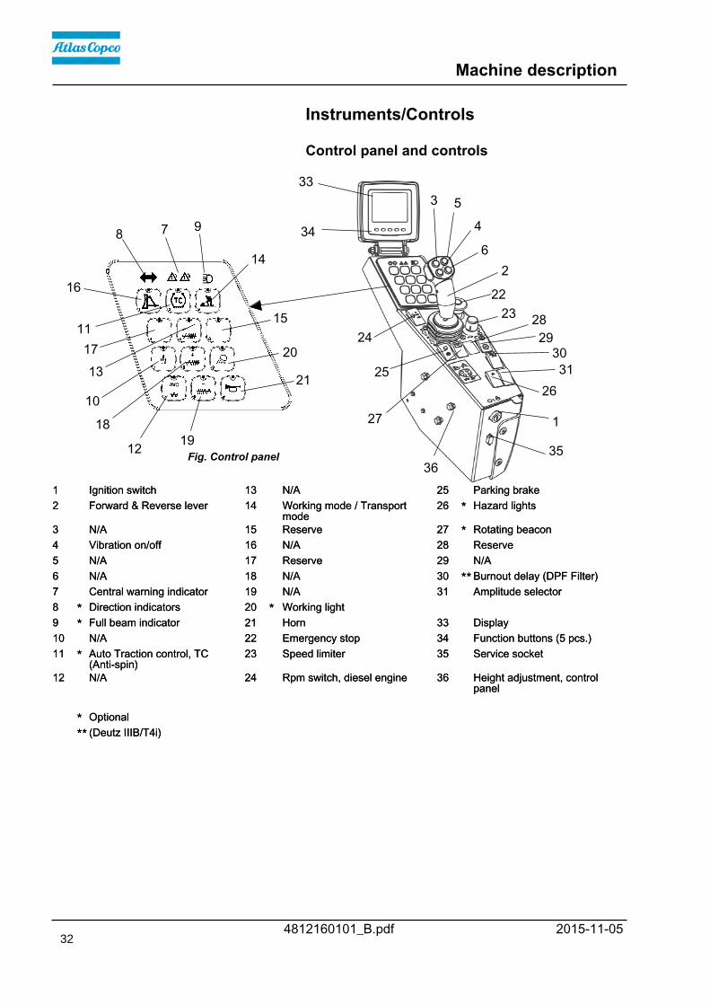
1 Ignition switch 13 N/A 25 Parking brake1 Ignition switch 13 N/A 25 Parking brake2 Forward & Reverse lever 14 Working mode / Transport
mode26 * Hazard lights2 Forward & Reverse lever 14 Working mode / Transport
mode26 * Hazard lights
3 N/A 15 Reserve 27 * Rotating beacon3 N/A 15 Reserve 27 * Rotating beacon4 Vibration on/off 16 N/A 28 Reserve4 Vibration on/off 16 N/A 28 Reserve5 N/A 17 Reserve 29 N/A5 N/A 17 Reserve 29 N/A6 N/A 18 N/A 30 ** Burnout delay (DPF Filter)6 N/A 18 N/A 30 ** Burnout delay (DPF Filter)7 Central warning indicator 19 N/A 31 Amplitude selector7 Central warning indicator 19 N/A 31 Amplitude selector8 * Direction indicators 20 * Working light8 * Direction indicators 20 * Working light9 * Full beam indicator 21 Horn 33 Display9 * Full beam indicator 21 Horn 33 Display10 N/A 22 Emergency stop 34 Function buttons (5 pcs.)10 N/A 22 Emergency stop 34 Function buttons (5 pcs.)11 * Auto Traction control, TC
(Anti-spin)23 Speed limiter 35 Service socket11 * Auto Traction control, TC
(Anti-spin)23 Speed limiter 35 Service socket
12 N/A 24 Rpm switch, diesel engine 36 Height adjustment, controlpanel
12 N/A 24 Rpm switch, diesel engine 36 Height adjustment, controlpanel
* Optional* Optional** (Deutz IIIB/T4i)** (Deutz IIIB/T4i)
36
32
Machine description
4812160101_B.pdf2015-11-05
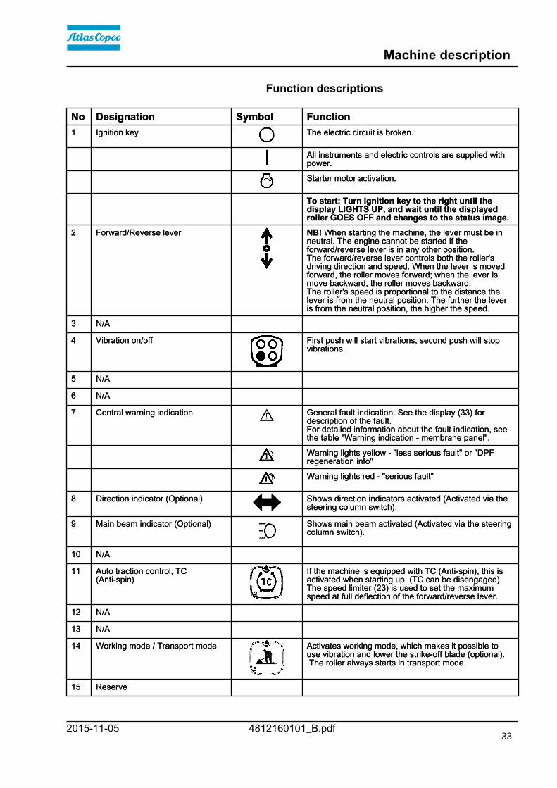
Function descriptions
No Designation Symbol FunctionNo Designation Symbol Function1 Ignition key The electric circuit is broken.1 Ignition key The electric circuit is broken.
All instruments and electric controls are supplied withpower.All instruments and electric controls are supplied withpower.
Starter motor activation.Starter motor activation.
To start: Turn ignition key to the right until thedisplay LIGHTS UP, and wait until the displayedroller GOES OFF and changes to the status image.
To start: Turn ignition key to the right until thedisplay LIGHTS UP, and wait until the displayedroller GOES OFF and changes to the status image.
2 Forward/Reverse lever NB! When starting the machine, the lever must be inneutral. The engine cannot be started if theforward/reverse lever is in any other position.The forward/reverse lever controls both the roller'sdriving direction and speed. When the lever is movedforward, the roller moves forward; when the lever ismove backward, the roller moves backward.The roller's speed is proportional to the distance thelever is from the neutral position. The further the leveris from the neutral position, the higher the speed.
2 Forward/Reverse lever NB! When starting the machine, the lever must be inneutral. The engine cannot be started if theforward/reverse lever is in any other position.The forward/reverse lever controls both the roller'sdriving direction and speed. When the lever is movedforward, the roller moves forward; when the lever ismove backward, the roller moves backward.The roller's speed is proportional to the distance thelever is from the neutral position. The further the leveris from the neutral position, the higher the speed.
3 N/A3 N/A
4 Vibration on/off First push will start vibrations, second push will stopvibrations.
4 Vibration on/off First push will start vibrations, second push will stopvibrations.
5 N/A5 N/A
6 N/A6 N/A
7 Central warning indication General fault indication. See the display (33) fordescription of the fault.For detailed information about the fault indication, seethe table "Warning indication - membrane panel".
7 Central warning indication General fault indication. See the display (33) fordescription of the fault.For detailed information about the fault indication, seethe table "Warning indication - membrane panel".
Warning lights yellow - "less serious fault" or "DPFregeneration info"Warning lights yellow - "less serious fault" or "DPFregeneration info"
Warning lights red - "serious fault"Warning lights red - "serious fault"
8 Direction indicator (Optional) Shows direction indicators activated (Activated via thesteering column switch).
8 Direction indicator (Optional) Shows direction indicators activated (Activated via thesteering column switch).
9 Main beam indicator (Optional) Shows main beam activated (Activated via the steeringcolumn switch).
9 Main beam indicator (Optional) Shows main beam activated (Activated via the steeringcolumn switch).
10 N/A10 N/A
11 Auto traction control, TC(Anti-spin)
If the machine is equipped with TC (Anti-spin), this isactivated when starting up. (TC can be disengaged)The speed limiter (23) is used to set the maximumspeed at full deflection of the forward/reverse lever.
11 Auto traction control, TC(Anti-spin)
If the machine is equipped with TC (Anti-spin), this isactivated when starting up. (TC can be disengaged)The speed limiter (23) is used to set the maximumspeed at full deflection of the forward/reverse lever.
12 N/A12 N/A
13 N/A13 N/A
14 Working mode / Transport mode Activates working mode, which makes it possible touse vibration and lower the strike-off blade (optional). The roller always starts in transport mode.
14 Working mode / Transport mode Activates working mode, which makes it possible touse vibration and lower the strike-off blade (optional). The roller always starts in transport mode.
15 Reserve15 Reserve
33

Machine description
4812160101_B.pdf 2015-11-05
No Designation Symbol FunctionNo Designation Symbol Function16 N/A16 N/A
17 Reserve17 Reserve
18 N/A18 N/A
19 N/A19 N/A
20 Working lights (Optional) By activating the working lights will turn ON.20 Working lights (Optional) By activating the working lights will turn ON.
21 Horn Press to sound the horn.21 Horn Press to sound the horn.
22 Emergency stop Brakes the roller and switches off the engine. Thepower supply goes off.NB! When starting the machine, the emergency stopmust be inactive.
22 Emergency stop Brakes the roller and switches off the engine. Thepower supply goes off.NB! When starting the machine, the emergency stopmust be inactive.
23 Speed limiter Limitation of the machine's max. speed (max.speed isobtained with full deflection of the F/R lever). Set theknob to the position for the desired max. speed.
23 Speed limiter Limitation of the machine's max. speed (max.speed isobtained with full deflection of the F/R lever). Set theknob to the position for the desired max. speed.
24 Rpm switch, diesel engine Three-position switch for idling (LO), intermediatespeed (MID) and working speed (HI).NB! When starting the machine, the control must bein idling position (LO). The diesel engine drops toeven lower revs during idling, more than approx. 10seconds if the F&R lever is in neutral.If the F&R lever is moved out of neutral the speed willincrease to the set speed again. If the machine isequipped with a fuel optimization system, MID isreplaced by ECO (and the switch is green).
24 Rpm switch, diesel engine Three-position switch for idling (LO), intermediatespeed (MID) and working speed (HI).NB! When starting the machine, the control must bein idling position (LO). The diesel engine drops toeven lower revs during idling, more than approx. 10seconds if the F&R lever is in neutral.If the F&R lever is moved out of neutral the speed willincrease to the set speed again. If the machine isequipped with a fuel optimization system, MID isreplaced by ECO (and the switch is green).
25 Parking brake To activate the brakes, press the top of the switch tochange the position of the switch.To release the brakes, press down the red part at thesame time as the switch and change the position ofthe switch.@@NOTE:When starting the machine, theparking brake must be activated.
25 Parking brake To activate the brakes, press the top of the switch tochange the position of the switch.To release the brakes, press down the red part at thesame time as the switch and change the position ofthe switch.@@NOTE:When starting the machine, theparking brake must be activated.
26 Hazard indicators (Optional) Activate the hazard warning light by depressing thebutton.
26 Hazard indicators (Optional) Activate the hazard warning light by depressing thebutton.
27 Rotating beacon (Optional) Activate the rotating beacon by pressing the switch. (Ifthe machine has two rotating beacons, both areactivated)
27 Rotating beacon (Optional) Activate the rotating beacon by pressing the switch. (Ifthe machine has two rotating beacons, both areactivated)
28 Reserve28 Reserve
29 N/A29 N/A
34

Machine description
4812160101_B.pdf2015-11-05
No Designation Symbol FunctionNo Designation Symbol Function30 Burnout delay DPF Filter (Deutz
Tier IIIB/4i)Delay burnout of the DPF filter (approx. 20 min.) bypressing and holding the switch for 3 sec.
30 Burnout delay DPF Filter (DeutzTier IIIB/4i)
Delay burnout of the DPF filter (approx. 20 min.) bypressing and holding the switch for 3 sec.
31 Amplitude selector31 Amplitude selector
35 Service socket Diagnostic socket.Gateway is connected here to read the CAN-Opensystem.
35 Service socket Diagnostic socket.Gateway is connected here to read the CAN-Opensystem.
Warning indication - membrane panel (Keypad)
"Yellow" - Warning"Yellow" - Warning- The engine has an alarm in category yellow (Alarm image shown in the display)- The engine has an alarm in category yellow (Alarm image shown in the display)- Communication with the display is interrupted- Communication with the display is interrupted- The fuel level is below <10%- The fuel level is below <10%- Charging absent- Charging absent(Deutz Tier IIIB/4i)(Deutz Tier IIIB/4i)- DPF - regeneration in progress Continuous yellow light that goes out
after 2 min- DPF - regeneration in progress Continuous yellow light that goes out
after 2 min- DPF - regeneration delayed Flashes yellow at approx. 1 Hz (once
per second)- DPF - regeneration delayed Flashes yellow at approx. 1 Hz (once
per second)- DPF - regeneration required (soot load >100%, but
other conditions not satisfied, e.g. cold engine)Flashes yellow at approx. 0.5 Hz(every two seconds)
- DPF - regeneration required (soot load >100%, butother conditions not satisfied, e.g. cold engine)
Flashes yellow at approx. 0.5 Hz(every two seconds)
"Red" - Warning Flashes red continuously"Red" - Warning Flashes red continuously- The engine has an alarm in category red (Alarm code shown in the display)- The engine has an alarm in category red (Alarm code shown in the display)- Communication with the engine is interrupted- Communication with the engine is interrupted- The engine temperature is too high- The engine temperature is too high- Low oil pressure in the engine- Low oil pressure in the engine- The air filter is clogged- The air filter is clogged- The hydraulic fluid temperature is too high- The hydraulic fluid temperature is too high- The hydraulic fluid filter is clogged- The hydraulic fluid filter is clogged
35
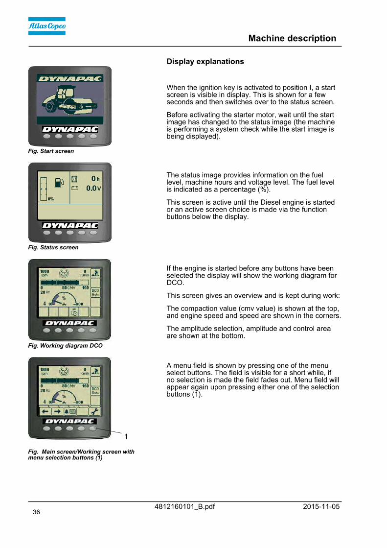
Machine description
4812160101_B.pdf 2015-11-05
Display explanations
Fig. Start screen
When the ignition key is activated to position I, a startscreen is visible in display. This is shown for a few seconds and then switches over to the status screen.
Before activating the starter motor, wait until the startimage has changed to the status image (the machineis performing a system check while the start image isbeing displayed).
Fig. Status screen
The status image provides information on the fuellevel, machine hours and voltage level. The fuel levelis indicated as a percentage (%).
This screen is active until the Diesel engine is startedor an active screen choice is made via the functionbuttons below the display.
Fig. Working diagram DCO
If the engine is started before any buttons have beenselected the display will show the working diagram forDCO.
This screen gives an overview and is kept during work:
The compaction value (cmv value) is shown at the top,and engine speed and speed are shown in the corners.
The amplitude selection, amplitude and control areaare shown at the bottom.
1
Fig. Main screen/Working screen withmenu selection buttons (1)
A menu field is shown by pressing one of the menuselect buttons. The field is visible for a short while, ifno selection is made the field fades out. Menu field willappear again upon pressing either one of the selectionbuttons (1).
36

Machine description
4812160101_B.pdf2015-11-05
Example of menu field. Scroll/Selection buttons to choosebetween available functions.Scroll/Selection buttons to choosebetween available functions.Alarm log button to display engine andmachine alarms.Alarm log button to display engine andmachine alarms.Settings/Button select menu, which opensthe main menu. Settings can be changedin the main menu.
Settings/Button select menu, which opensthe main menu. Settings can be changedin the main menu.Exit/Return button returns 1 step at once.Pressing the button (approx. 2 sec.)displays the main menu again.
Exit/Return button returns 1 step at once.Pressing the button (approx. 2 sec.)displays the main menu again.
Fig. Speed diagram
The speed diagram shows the speed in the middle ofthe diagram. (km/h or mph)
The engine speed, vibration frequency, cmv value forcompaction meter and gradient value in % (optional),are shown in the corners.
Fig. Temperature screen
The temperature screen shows the temperature of theengine (top of display) and hydraulic fluid (bottom ofdisplay). The values are shown in Celsius orFahrenheit, depending on the choice of unit system.
When an engine alarm is activated, the alarm is shownon the display.
The engine alarm is sent out from the engine ECM,which handles the monitoring of the engine functions.
The message, which consists of an SPN and FMIcode, can be interpreted via the engine supplier errorcode list.
The alarm message shown is acknowledged bypressing the "OK" button on the display.
37

Machine description
4812160101_B.pdf 2015-11-05
When a machine alarm is activated the alarm is shownon the display, plus a warning text that describes thealarm.
The alarm message shown is acknowledged bypressing the "OK" button on the display.
38

Machine description
4812160101_B.pdf2015-11-05
Machine alarm
Symbol Designation FunctionSymbol Designation FunctionWarning symbol, hydraulic fluid filter If the symbol is shown when the diesel engine is running at
full speed, the hydraulic fluid filter must be changed.Warning symbol, hydraulic fluid filter If the symbol is shown when the diesel engine is running at
full speed, the hydraulic fluid filter must be changed.
Warning symbol, clogged air filter If this symbol is shown when the engine is running at fullspeed, the air filter must be checked/replaced.
Warning symbol, clogged air filter If this symbol is shown when the engine is running at fullspeed, the air filter must be checked/replaced.
Warning symbol, battery charging If the symbol is shown when the engine is running, thenthe alternator is not charging.Switch off the engine and locate the fault.
Warning symbol, battery charging If the symbol is shown when the engine is running, thenthe alternator is not charging.Switch off the engine and locate the fault.
Warning symbol, engine temperature If this symbol is shown, the engine is too hot. Stop theengine immediately and locate the fault.Refer also to the engine manual.
Warning symbol, engine temperature If this symbol is shown, the engine is too hot. Stop theengine immediately and locate the fault.Refer also to the engine manual.
Warning symbol, hydraulic fluidtemperature
This symbol is shown when the hydraulic fluid is too hot.Do not drive the roller; allow the fluid to cool by running theengine on idle, and then locate the fault.
Warning symbol, hydraulic fluidtemperature
This symbol is shown when the hydraulic fluid is too hot.Do not drive the roller; allow the fluid to cool by running theengine on idle, and then locate the fault.
Warning symbol, hydraulic fluidtemperature (coldl)
This symbol is shown when the hydraulic fluid is too coldfor the use of vibrations at full speed. (The oil must over 5degrees (C))Is the optional ECO chosen you can vibrate in ECO modeeven if the oil has not reached 5 degrees (C).
Warning symbol, hydraulic fluidtemperature (coldl)
This symbol is shown when the hydraulic fluid is too coldfor the use of vibrations at full speed. (The oil must over 5degrees (C))Is the optional ECO chosen you can vibrate in ECO modeeven if the oil has not reached 5 degrees (C).
Warning symbol, low fuel level If this symbol is shown, there is less than 10% of the fuelleft.
Warning symbol, low fuel level If this symbol is shown, there is less than 10% of the fuelleft.
Warning symbol, low oil pressure,diesel engine
If this symbol is shown, the engine's oil pressure is too low.Switch off the engine immediately.
Warning symbol, low oil pressure,diesel engine
If this symbol is shown, the engine's oil pressure is too low.Switch off the engine immediately.
Warning symbol, low coolant level If this symbol is shown, fill with coolant/glycol and searchfor leaks.
Warning symbol, low coolant level If this symbol is shown, fill with coolant/glycol and searchfor leaks.
Warning symbol, water in the fuel If this symbol is shown, the engine must be stopped andthe fuel pre-filter drained of water.
Warning symbol, water in the fuel If this symbol is shown, the engine must be stopped andthe fuel pre-filter drained of water.
Warning symbol, low hydraulic fluidlevel
If this symbol is shown, fill with hydraulic fluid to the correctlevel and search for leaks.
Warning symbol, low hydraulic fluidlevel
If this symbol is shown, fill with hydraulic fluid to the correctlevel and search for leaks.
39

Machine description
4812160101_B.pdf 2015-11-05
Dynapac Sub System (DSS)
DSScode
Description NoteDSScode
Description Note
1 Speed sensor, front Optional1 Speed sensor, front Optional2 Speed sensor, rear2 Speed sensor, rear3 Inclination sensor Optional3 Inclination sensor Optional4 DCM Optional4 DCM Optional5 IO-Card5 IO-Card6 Cooling fan speed sensor6 Cooling fan speed sensor7 Vibration frequency meter Supervision only active if Adjustable frequency or
ECO available.Optional7 Vibration frequency meter Supervision only active if Adjustable frequency or
ECO available.Optional
8 Power group 1 see Fuse 38 Power group 1 see Fuse 39 Power group 2 see Fuse 49 Power group 2 see Fuse 410 Power group 3 see Fuse 510 Power group 3 see Fuse 511 Power group 4 see Fuse 611 Power group 4 see Fuse 6
Alarms received are logged and can be seen byselecting Display alarms.
Selection of Display alarms.
"ENGINE ALARM"
Logged engine alarms.
40
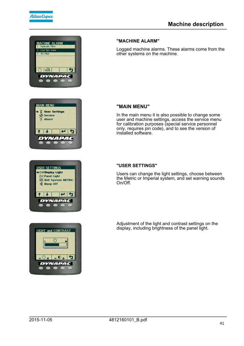
Machine description
4812160101_B.pdf2015-11-05
"MACHINE ALARM"
Logged machine alarms. These alarms come from theother systems on the machine.
"MAIN MENU"In the main menu it is also possible to change someuser and machine settings, access the service menufor calibration purposes (special service personnelonly, requires pin code), and to see the version ofinstalled software.
"USER SETTINGS"
Users can change the light settings, choose betweenthe Metric or Imperial system, and set warning soundsOn/Off.
Adjustment of the light and contrast settings on thedisplay, including brightness of the panel light.
41

Machine description
4812160101_B.pdf 2015-11-05
"SERVICE MENU"
The service menu is also accessible via the mainmenu for adjustments.
"ADJUSTMENTS"
"TESTMODES" - Installation personnel only, requirespin code.
42

Machine description
4812160101_B.pdf2015-11-05
"CALIBRATION" - service personnel only, requirespassword.
"EDC Calibration" used to calibrate the joystick andspeed potentiometer.
"TX Program" only used to change software in thedisplay and requires special equipment and know-how.
"EDC CALIBRATION"
To calibrate, move the joystick fully forward (F) andpress in both black buttons on the top of the joystick.(See also manual W3025)
Continue in the same way with the other positions forthe joystick (N), (R) and the speed potentiometer.
Press the disk button to save the values.
"ABOUT"
It is also possible to see the version of the installedsoftware.
"MACHINE SETTINGS"
In the setting for "DCO CONTROL MODE" the DCOstatus can be set to automatic or manual mode.
43

Machine description
4812160101_B.pdf 2015-11-05
Operator help when startingWhen trying to start the machine without having setone, two or three of the conditions required to startmachine, the missing conditions are shown in thedisplay.
The missing conditions must be set before it ispossible to start the machine.
Conditions that must be set:
- Activated P-brake
- Selector lever in neutral
- Speed selector for diesel engine in low (Low = idling)(not all models)
Operator help WorkmodeWhen attempting to activate
- Vibration
- Strike-off blade (Optional) (Not possible to use withDCO)
with the machine in Transport mode the display willshow "Workmode" for a few seconds.
To activate the above functions it is necessary tomake sure that the machine's Workmode is activated.
44

Machine description
4812160101_B.pdf2015-11-05
Display when activating choice via the buttonset.
=DCO error, seetable
DCO view andstatus
The parking symbol is shown when the parking brake isactivated.
= Display of alarm, see table for information.
= Vibration is enabled in the operating position.
DCO view and statusControl range:Grey marking shows activecontrol range for selectedamplitude mode.
Amplitude selection:Shows amplitude mode to limitmaximum amplitude.
Amplitude:The amplitude indicator showswhich amplitude the machinehas at each stage of thecompaction. 0-100 %.
Status mode:Shows current DCO status. SeeTable.
Automatic Control ModeAutomatic Control Mode
Automatic Control Mode with vibrationswitch enabled.Automatic Control Mode with vibrationswitch enabled.
Manual Control Mode.Manual Control Mode.
Manual Control Mode with vibrationswitch enabled.Manual Control Mode with vibrationswitch enabled.
45

Machine description
4812160101_B.pdf 2015-11-05
Error messages (DCO)
Symbol Designation FunctionSymbol Designation FunctionZero search fault This fault can occur when the machine is started if it takes too long to
position/calibrate the amplitude to 0.The fault can occur if there is a fault on a sensor/cable/connector for thissystem.
Zero search fault This fault can occur when the machine is started if it takes too long toposition/calibrate the amplitude to 0.The fault can occur if there is a fault on a sensor/cable/connector for thissystem.
Sensor fault This fault can occur during vibration.If one of the two sensors for amplitude positioning malfunctions then thisfault will occur. There could have a fault on the actual sensor, or on thecable/connector.
Sensor fault This fault can occur during vibration.If one of the two sensors for amplitude positioning malfunctions then thisfault will occur. There could have a fault on the actual sensor, or on thecable/connector.
Movement fault This fault can occur during vibration.The fault occurs if the system does not detect any change in the amplitudewhen this is requested. It could be a result of mechanical or hydraulic inertia,or if both sensors for amplitude positioning malfunction at the same time.
Movement fault This fault can occur during vibration.The fault occurs if the system does not detect any change in the amplitudewhen this is requested. It could be a result of mechanical or hydraulic inertia,or if both sensors for amplitude positioning malfunction at the same time.
Min limit fault This fault can occur during vibration.If the mechanical system for amplitude controlling should for some reasonposition itself outside the valid limits (low amplitude), this fault occurs.
Min limit fault This fault can occur during vibration.If the mechanical system for amplitude controlling should for some reasonposition itself outside the valid limits (low amplitude), this fault occurs.
Max limit fault This fault can occur during vibration.If the mechanical system for amplitude controlling should for some reasonposition itself outside the valid limits (high amplitude), this fault occurs.
Max limit fault This fault can occur during vibration.If the mechanical system for amplitude controlling should for some reasonposition itself outside the valid limits (high amplitude), this fault occurs.
Direction fault This fault occurs if the system detects that the direction of the movement iswrong in relation to the required change in amplitude.It could be a result of either an incorrect power or hydraulic connection.
Direction fault This fault occurs if the system detects that the direction of the movement iswrong in relation to the required change in amplitude.It could be a result of either an incorrect power or hydraulic connection.
46

Machine description
4812160101_B.pdf2015-11-05
Instruments and controls, cab
Fig. Right rear cab post 15. Hammer for emergency exit
ACC Heater/AC
10
14
Radio/CD
8
9
15
1 2 3 4
5 6 7
Fig. Cab roof, front
47

Machine description
4812160101_B.pdf 2015-11-05
Function description of instruments andcontrols in the cab
No Designation Symbol FunctionNo Designation Symbol Function1 Heater control Turn to the right to increase heating.
Turn to the left to reduce heating.1 Heater control Turn to the right to increase heating.
Turn to the left to reduce heating.
2 Ventilation fan, switch In the left position, the fan is off.Turning the knob to the right increases thevolume of air entering the cab.
2 Ventilation fan, switch In the left position, the fan is off.Turning the knob to the right increases thevolume of air entering the cab.
3 Air conditioning, switch Starts and stops the air conditioning.3 Air conditioning, switch Starts and stops the air conditioning.
4 Cab air recirculation, switch Pressing the top opens the air damper so thatfresh air comes into the cab.Pressing the bottom closes the damper so thatthe air recirculates inside the cab.
4 Cab air recirculation, switch Pressing the top opens the air damper so thatfresh air comes into the cab.Pressing the bottom closes the damper so thatthe air recirculates inside the cab.
5 Front wiper, switch Press to operate the front screen wiper.5 Front wiper, switch Press to operate the front screen wiper.
6 Rear wiper, switch Press to operate the rear screen wiper.6 Rear wiper, switch Press to operate the rear screen wiper.
7 Front and rear window screenwashers, switch
Press the upper edge to activate the front screenwashers.Press the lower edge to activate the rear screenwashers.
7 Front and rear window screenwashers, switch
Press the upper edge to activate the front screenwashers.Press the lower edge to activate the rear screenwashers.
8 Fuse box Contains fuses for the electrical system in thecab.
8 Fuse box Contains fuses for the electrical system in thecab.
9 Front wiper, intermittent Intermittent function for front wiper.9 Front wiper, intermittent Intermittent function for front wiper.
10 Automatic Climate Control (ACC)(micro ECC)
Automatic control of the air conditioning.10 Automatic Climate Control (ACC)(micro ECC)
Automatic control of the air conditioning.
14 Defroster nozzle Turn the nozzle to direct the flow of air.14 Defroster nozzle Turn the nozzle to direct the flow of air.
15 Hammer for emergency exit To escape from the cab in an emergency,release the hammer and break the openingwindows on the right-hand side.
15 Hammer for emergency exit To escape from the cab in an emergency,release the hammer and break the openingwindows on the right-hand side.
48

Machine description
4812160101_B.pdf2015-11-05
Using the cab controlsDefroster
To quickly remove ice or mist, make sure that only thefront and rear air nozzles are open.
Turn the heater and fan dial (1 and 2) to max.
Adjust the nozzle so that it blows on the window to bede-iced, or to remove mist.
1 2AC
3 4
Heat
If the cab is cold, open the lower nozzle on the frontcolumns and the middle nozzles just over the controlsfor the heater and fan.
Turn to max heat and max fan speed.
When the required temperature has been reached,open the other nozzles and if necessary turn down theheat and fan speed.
AC/ACC
NOTE: When using AC/ACC all the windows must beclosed for the system to work efficiently.
To quickly reduce the temperature in the cab, adjustthe following settings on the control panel.
Turn on AC (3) and set the fresh air (4) in the lowerposition to switch off the fresh air valve.
Set the heater control (1) to minimum and turn up thefan speed (2). Keep only the front middle nozzles inthe ceiling open.
When the temperature has dropped to a comfortablelevel, adjust the required temperature on the heatercontrol (1) and reduce the fan speed (2).
Now open the remaining nozzles in the roof to achievea comfortable temperature in the cab.
Reset the fresh air button (4) to the upper position forfresh air.
49

Machine description
4812160101_B.pdf 2015-11-05
ACC - Control panel1. LCD Display
During normal operation, the set-point temperature,blower speed, operation mode and fresh/re-circulatedair selection are displayed.
2. SET / SELECT Button
Under normal operation button is used for selectingbetween modes.
(Also used in Test / diagnostics mode for differentchoices)
3. Power Button
Device ON/OFF.
Main display screen1. Air mix control
The air mix can be set to full fresh air or fullre-circulated air.
2. Mode
Displays the mode, "Automatic", "Heat", "Cool" and"Defrost"
3. Temperature Set-point
Displays current inside set-point temperature.
4. Blower speed
Displays current blower speed setting.
ACC - Operation menusMain screen
When the unit is turned on, the main screen willappear. Current set-point temperature, climat controlmode, air-circulation and blower speed are displayed.
A small warning icon appears if there is somethingwrong with the system.
Blower speed settings:
Press SET / SELECT button until the blower iconappears, then turn clockwise to increase blower speedand counterclockwise to decrease blower speed with5% increments.
The blower speed can not be adjusted in defrost mode(Defrost).
50

Machine description
4812160101_B.pdf2015-11-05
Climate Control mode settings:
Press SET / SELECT button until the climate controlmode icon appears, and then turn the button until therequired mode is displayed.
AUTO The system runs automatically to keep the temperature that isselected (set-point temperature).
AUTO The system runs automatically to keep the temperature that isselected (set-point temperature).
Cool A / C compressor is running to cool the interior temperature.Heating valve is turned off while cooling off ("Cool") is selected.
Cool A / C compressor is running to cool the interior temperature.Heating valve is turned off while cooling off ("Cool") is selected.
Heat Interior temperature warms up with the electronic heater valve.A / C compressor is turned off while warming ("Heat") isselected
Heat Interior temperature warms up with the electronic heater valve.A / C compressor is turned off while warming ("Heat") isselected
Defrost When defrosting ("Defrost") is activated, the A / C compressoris turned on, the blower is turned on full speed and the heatervalve is fully open.
Defrost When defrosting ("Defrost") is activated, the A / C compressoris turned on, the blower is turned on full speed and the heatervalve is fully open.
Air circulation setting:
Press the SET button until the air circulation modeicon appears.
Turn the knob clockwise to fully recirculated airTurn the knob clockwise to fully recirculated air
or counterclockwise full fresh air.or counterclockwise full fresh air.
Display settings:
To adjust the display settings and the temperaturescale, press the SET button until the display settingsscreen appears, then turn the SET button clockwise orcounterclockwise to adjust the settings.
51

Machine description
4812160101_B.pdf 2015-11-05
Turning HVAC system OFF:
In the main screen, press the Power button to turn offthe HVAC system. When the system is turned off, thebacklight will turn off and the interior temperature willbe displayed on the screen.
To turn off the HVAC system from Defrost mode,press the Power button until the HVAC system returnsto the AUTO mode, then press the Power button againto turn off the HVAC unit.
Diesel Heat mode (if diesel heater is installed):
When a Diesel heat mode signal is received, thebacklight will be turned off, the blower will run at 15%,the heater valve will be fully opened and the aircirculation will switch to fresh air until the after coiltemperature is above 20 º C (78 º F). When the aftercoil temperature is above 20 º C (78 º F), the blowerwill run at a preset speed. No other function is allowed.
Electrical system3
Fig. Main switchbox 1. Control unit (ECU)(A7) 2. Fuse card (A6) 3. Main relay (K2) 4. Power supply (A10), compactionmeter(DCM) (Optional) 5. Power converter 24/12V DC (T1) 6. Tilt sensor (B14) (Optional)
12
4 5
6
The machine's main switchbox (1) is located on therear left of the operator's platform. There is a plasticcover over the distribution box and fuses.
On the plastic cover there is a 24V socket (X96) and a12V socket (X98)(optional).
52

Machine description
4812160101_B.pdf2015-11-05
Fuses in the main switchbox (Cummins)
Fig. Fuses
123456789
10111213141516
The figure shows the position of the fuses.
The table below gives fuse amperage and function. Allfuses are flat pin fuses.
1. Main relay, 24V outlet enginecompartment
10A 9. Reserve1. Main relay, 24V outlet enginecompartment
10A 9. Reserve
2. ECU, Outlet boot loading, I/O board,display
5A 10. Reserve2. ECU, Outlet boot loading, I/O board,display
5A 10. Reserve
3. ECU PWR1, Speed sensor 10A 11. 12V outlet, Radio/CD 10A3. ECU PWR1, Speed sensor 10A 11. 12V outlet, Radio/CD 10A
4. ECU PWR2, Forward/Reverse lever 10A 12. GPS, DCM, DCO, tilt sensor 10A4. ECU PWR2, Forward/Reverse lever 10A 12. GPS, DCM, DCO, tilt sensor 10A
5. ECU PWR 3 20A 13. Reserve5. ECU PWR 3 20A 13. Reserve
6. ECU PWR 4 20A 14. DCA 10A6. ECU PWR 4 20A 14. DCA 10A
7. 24V outlet operator's station,Tachograph
10A 15. Indicator relay 7.5A7. 24V outlet operator's station,Tachograph
10A 15. Indicator relay 7.5A
8. Hydraulic/Fuel sensor, Engine 10A 16. Driving lights 10A8. Hydraulic/Fuel sensor, Engine 10A 16. Driving lights 10A
Fuses at master switch (Cummins)
Fig. Cover, left side 1. Fuse box 2. Batteries (x2) 3. Battery disconnector plate
1
32
The fuse box (1) is located inside the cover by thesteps on the left-hand side of the roller.
This is also where the batteries (2) are, and the starterrelay (4) and preheating relay (5) are placed behindthe battery disconnector plate (3).
5
4
4. Starter relay, 50A5. Preheating relay, 120A
53

Machine description
4812160101_B.pdf 2015-11-05
Fuse box at master switch (Cummins)
Fig. Fuse box, battery disconnectorswitch
1
3
2
4
The figure shows the position of the fuses.
The amperage and function of the fuses are shownbelow. All fuses are flat pin fuses.
1. Main fuse 50A1. Main fuse 50A2. Cab 30A2. Cab 30A3. Diesel engine ECU 30A (IIIA/T3)3. Diesel engine ECU 30A (IIIA/T3)
60A (IIIB/T4i)60A (IIIB/T4i)4. Grid heater 40A4. Grid heater 40A
Fuses in the main switchbox (Deutz)
Fig. Fuses
123456789
10111213141516
The figure shows the position of the fuses.
The table below gives fuse amperage and function. Allfuses are flat pin fuses.
54

Machine description
4812160101_B.pdf2015-11-05
1. Main relay, 24V outlet enginecompartment
10A 9. ***
Glow plug relayNOX sensor
7,5A15A
1. Main relay, 24V outlet enginecompartment
10A 9. ***
Glow plug relayNOX sensor
7,5A15A
2. ECU, Outlet boot loading, I/O board,display
5A 10. ***
ReserveDiesel engine 10A
2. ECU, Outlet boot loading, I/O board,display
5A 10. ***
ReserveDiesel engine 10A
3. ECU PWR1, Speed/Frequency sensor 10A 11. 12V outlet, Radio/CD 10A3. ECU PWR1, Speed/Frequency sensor 10A 11. 12V outlet, Radio/CD 10A
4. ECU PWR2, Forward/Reverse lever 10A 12. GPS, DCM, DCO, tilt sensor 10A4. ECU PWR2, Forward/Reverse lever 10A 12. GPS, DCM, DCO, tilt sensor 10A
5. ECU PWR 3 20A 13. Reserve5. ECU PWR 3 20A 13. Reserve
6. ECU PWR 4 20A 14. DCA 10A6. ECU PWR 4 20A 14. DCA 10A
7. 24V outlet operator's station,Tachograph
10A 15. Indicator relay 7.5A7. 24V outlet operator's station,Tachograph
10A 15. Indicator relay 7.5A
8. Hydraulic/Fuel sensor, Engine 10A 16. Driving lights 10A8. Hydraulic/Fuel sensor, Engine 10A 16. Driving lights 10A
* (IIIA/T3)* (IIIA/T3)
** (IIIB/T4i)** (IIIB/T4i)
Fuses at master switch (Deutz)
Fig. Cover, left side 1. Fuse box 2. Engine control unit (ECM-box) 3. Fuse 30A, ECM-box (IIIB/T4i) Relay 20A, ECM-box (IIIA/T3) 4. Batteries (2 pcs)
1
2
34
The fuse box (1) is located inside the cover with thesteps on the left-hand side of the roller. The engine'scontrol unit (ECM-box) (2) and its fuse/relay (3) as wellas the batteries (4), are also located here.
The ECM box's fuse/relay (3) is located on the back ofthe monting plate for the master switch.
Is the machine equipped with Deutz engine IIIA/T3there is a starter relay (5) and a grid heater relay (6)on the plate at the diesel engine control unit (ECMbox).
5
65. Starter relay, 50A6. Grid heater relay, 120A
55

Machine description
4812160101_B.pdf 2015-11-05
Fuse box at master switch (Deutz)
Fig. Fuse box, battery disconnectorswitch
1
3
2
4
The figure shows the position of the fuses.
The amperage and function of the fuses are shownbelow. All fuses are flat pin fuses.
1. Main fuse 50A1. Main fuse 50A2. Cab 30A2. Cab 30A3. * Diesel engine ECU 30A3. * Diesel engine ECU 30A3. ** Burner, air pump 60A3. ** Burner, air pump 60A4. * Grid heater 40A4. * Grid heater 40A4. ** Burner, heater plug 25A4. ** Burner, heater plug 25A
* (IIIA/T3)* (IIIA/T3)** (IIIB/T4i)** (IIIB/T4i)
Fuses in cab
Fig. Cab roof fuse box (F7)
1. Interior lighting 10A1. Interior lighting 10A2. Windscreen wiper/washers 10A2. Windscreen wiper/washers 10A3. Cab fan 15A3. Cab fan 15A4. Reserve4. Reserve5. Reserve5. Reserve6. Reserve6. Reserve7. Reserve7. Reserve8. Reserve8. Reserve
The electrical system in the cab has a separate fusebox located on the front right side of the cab roof.
The figure shows fuse amperage and function.
All fuses are flat pin fuses.
56

Operation
4812160101_B.pdf2015-11-05
Operation
Before starting
Master switch - Switching on
1
Fig. Cover, left side 1. Battery disconnector switch
Remember to carry out daily maintenance. Refer tothe maintenance instructions.
The battery disconnector switch is located inside thecover by the steps on the left-hand side of the roller.Turn the key (1) to the On position. The roller is nowsupplied with power.
The cover must be unlocked when operating, sothat the battery can be quickly disconnected ifnecessary.
The cover must be unlocked when operating, sothat the battery can be quickly disconnected ifnecessary.
1 2
3
4
Fig. Operator's seat1. Lock pack- Length adjustment2. Weight adjustment3. Back support angle4. Seat belt
Operator's seat - AdjustmentAdjust the operator’s seat so that the position iscomfortable and so that the controls are within easyreach.
The seat can be adjusted as follows.
- Length adjustment (1)
- Weight adjustment (2)
- Back support angle (3)
Always make sure that the seat is secure beforebeginning operation.Always make sure that the seat is secure beforebeginning operation.Do not forget to use the seatbelt (4).Do not forget to use the seatbelt (4).
57

Operation
4812160101_B.pdf 2015-11-05
Belt reminderThe machine can be equipped with seat belt with beltreminder.
Unless the seat belt is used, a warning image appearin the display and a warning buzzer sounds to alert thedriver to use the seat belt.
Operator's seat, comfort - Adjustments6
4
2
1
3
5
Fig. Operator’s seat 1. Lever - length adjustment 2. Wheel - height adjustment 3. Wheel - seat cushion inclination 4. Wheel - backrest inclination 5. Wheel - armrest inclination 6. Wheel - lumbar supportadjustment
Adjust the operator's seat so that the position iscomfortable and so that the controls are within easyreach.
The seat can be adjusted as follows: - Length adjustment (1) - Height adjustment (2) - Seat-cushion inclination (3) - Backrest inclination (4) - Armrest inclination (5) - Lumbar support adjustment (6)
Always ensure that the seat is locked in positionbefore operating the roller.Always ensure that the seat is locked in positionbefore operating the roller.
58

Operation
4812160101_B.pdf2015-11-05
Control panel, adjustments
1
2
Fig. Operator's station 1. Locking lever - rotation 2. Locking lever - steering columnangle
The control unit has two adjustment options, rotationand steering column angle.
For rotation, lift the lever (1).Ensure that the control unit locks in position beforeoperating the machine.
Release locking lever (2) to adjust the steering columnangle. Lock the steering column in the new position.
To adjust the operator's seat, see the section forbasic/comfort seat.
Adjust all settings when the machine is stationary.Adjust all settings when the machine is stationary.
Always ensure that the seat is in locked positionbefore operating the roller.Always ensure that the seat is in locked positionbefore operating the roller.
Parking brake
1
Fig. Control panel 1. Parking brake
Ensure that the parking brake (1) is definitelyswitched on.Ensure that the parking brake (1) is definitelyswitched on.
Brake is always activated in Neutral position.(automatic 1.5 sec.)
The parking brake must be activated to start themachine!
59

Operation
4812160101_B.pdf 2015-11-05
Display - Control
1
2
Fig. Control panel1. Ignition key2. Status screen
Sit down for all operations.
Turn the ignition key (1) to position I, the start screenwill be shown in display.
4
5
3
Fig. Status image 3. Fuel level 4. Hourmeter 5. Voltmeter
Check that the voltmeter (5) reads at least 24 volts,and that the fuel gauge (3) show a reading.
The hourmeter (4) registers and shows the totalnumber of hours the engine has run.
60

Operation
4812160101_B.pdf2015-11-05
InterlockThe roller is equipped with Interlock.
The diesel engine with switch off after 7 seconds if theoperator gets off the seat when goingforwards/backwards.
If the control is in neutral when the operator stands upa buzzer will go on until the parking brake is activated.
If the parking brake is activated, the diesel engine willnot stop if the forward/reverse lever is moved out ofneutral.
The diesel engine will switch off immediately if for anyreason the forward/reverse lever is moved out ofneutral when the operator is not sitting down and theparking brake has not been activated.
Sit down for all operations!Sit down for all operations!
Operator position
1
3
2
4
Fig. Operator's station1. Seat belt2. ROPS structure3. Rubber element4. Anti-slip
If a ROPS (2) (Roll Over Protective Structure) or a cabis fitted to the roller, always wear the seat belt (1)provided and wear a protective helmet.
Replace the seat belt (1) if it shows signs ofwear or has been subjected to high levels offorce.
Replace the seat belt (1) if it shows signs ofwear or has been subjected to high levels offorce.
Check that rubber elements (3) on the platformare intact. Worn elements will impair comfort.Check that rubber elements (3) on the platformare intact. Worn elements will impair comfort.
Ensure that the anti-slip (4) on the platform is ingood condition. Replace where anti-slip friction ispoor.
Ensure that the anti-slip (4) on the platform is ingood condition. Replace where anti-slip friction ispoor.
If the machine is fitted with a cab, make sure thatthe door is closed when in motion.If the machine is fitted with a cab, make sure thatthe door is closed when in motion.
61

Operation
4812160101_B.pdf 2015-11-05
View
Fig. view
Before starting, make sure that the view forwards andbackwards is unobstructed.
All cab windows should be clean and the rear viewmirrors should be correctly adjusted.
62

Operation
4812160101_B.pdf2015-11-05
Starting
Starting the engine
2
1
Fig. Control panel 1. F/R lever 2. Rpm switch 3. Ignition key
3
Make sure that the emergency stop is OFF and theparking brake ON.
Set the forward/reverse lever (1) in neutral position,and set the speed selector (2) in the idling position(LO) or (ECO) if that option is installed on the machine.
The diesel engine cannot be started in any otherposition of the controls.
Turn the ignition key (3) right to position I and thenengage the starter by turning it full right. Release backto I as soon as the engine starts.
Do not run the starter motor for too long (max. 30seconds). If the engine will not start, wait aminute before trying again.
Do not run the starter motor for too long (max. 30seconds). If the engine will not start, wait aminute before trying again.
At the start of the diesel engine when the ambienttemperature is below +10 ° C (50 ° F), it must bewarmed up at idle (low speed) until the hydraulic oiltemperature exceeds +10 ° C (50 ° F).
Ensue that there is good ventilation (air extraction)if the engine is run indoors. Risk of carbonmonoxide poisoning.
Ensue that there is good ventilation (air extraction)if the engine is run indoors. Risk of carbonmonoxide poisoning.
Figure. Display - Status image
While the engine is warming up, check that the fuelindicator shows the level and that the charge shows atleast 24V.
When starting and driving a machine that is cold,remember that the hydraulic fluid is also cold andthat braking distances can be longer than normaluntil the machine reaches the working temperature.
When starting and driving a machine that is cold,remember that the hydraulic fluid is also cold andthat braking distances can be longer than normaluntil the machine reaches the working temperature.
The machine always starts in Transport modeand without the option of vibration.The machine always starts in Transport modeand without the option of vibration.
63

Operation
4812160101_B.pdf 2015-11-05
Driving
Operating the roller
Fig. Control panel 1. Speed selector 2. Parking brake knob 2. Forward/Reverse lever
31
2
Under no circumstances is the machine to beoperated from the ground. The operator must beseated inside the machine during all operation.
Under no circumstances is the machine to beoperated from the ground. The operator must beseated inside the machine during all operation.
Activate working speed (1) = HI or ECO if available.
In ECO, the machine automatically regulates theengine speed according to requirements.
If the machine is only to be transported, ECO shouldbe selected instead.
Check that the steering is working correctly by turningthe steering wheel once to the right and once to theleft while the roller is stationary.
Make sure that the area in front of andbehind the roller is clear.Make sure that the area in front of andbehind the roller is clear.
Release the parking brake button (2) bysliding the red lock on the buttonbackwards and changing the position ofthe lever.
Release the parking brake button (2) bysliding the red lock on the buttonbackwards and changing the position ofthe lever.
2
3
Fig. Control panel 1. TC (Anti-spin) 2. Forward/Reverse lever 3. Potentiometer (speed limiter)
1
Machine with TC (Anti-Spin)
TC (Anti-Spin) (1) is activated by default (LED lit).
Position the speed control (3) in suitable position.
64

Operation
4812160101_B.pdf2015-11-05
TC (Anti-Spin) activated/disengaged is shown in thecenter of the speedometer.
Fig. The display shows whether TC(Anti-Spin) is activated or disengaged
Carefully move the forward/reverse lever (2) forwardsor backwards, depending on which direction of travelis required.
Speed increases as the lever is moved away from theneutral position.
Slopes (TC (Anti-Spin))
To optimize available pulling force and protect themachine's engine against over-revving while workingor during transport driving on steep slopes (>10%),you must select low setting on the speed limiter(potentiometer).
Never drive with a higher gear/at a faster speed thatthe machine requires to climb up the same slope!
65

Operation
4812160101_B.pdf 2015-11-05
Interlock/Emergency stop/Parking brake -Check
The interlock, emergency stop and parking brake mustbe checked daily before operating. A function check ofthe interlock and emergency stop requires a restart.
The interlock, emergency stop and parking brake mustbe checked daily before operating. A function check ofthe interlock and emergency stop requires a restart.
The interlock function is checked by the operatorstanding up from the seat when the roller is movingvery slowly forwards/backwards. (Check in bothdirections). Hold the steering wheel firmly and braceyourself for a sudden stop. A buzzer goes on and after7 seconds the engine switches off and the brakes areactivated.
The interlock function is checked by the operatorstanding up from the seat when the roller is movingvery slowly forwards/backwards. (Check in bothdirections). Hold the steering wheel firmly and braceyourself for a sudden stop. A buzzer goes on and after7 seconds the engine switches off and the brakes areactivated.
Check the function of the emergency stop by pressingthe emergency stop button.Check the function of the emergency stop by pressingthe emergency stop button.
Check the function of the parking brake by activatingthe parking brake when the roller is moving veryslowly forwards/backwards. (Check in bothdirections). Hold the steering wheel and brace yourselffor a sudden stop when the brakes are activated. Theengine does not switch off.
Check the function of the parking brake by activatingthe parking brake when the roller is moving veryslowly forwards/backwards. (Check in bothdirections). Hold the steering wheel and brace yourselffor a sudden stop when the brakes are activated. Theengine does not switch off.
66

Operation
4812160101_B.pdf2015-11-05
Burnout of DPF filter - (IIIB/T4i)The machine is equipped with a diesel particle filter(DPF filter), and the engine performs an automaticburnout of soot and ash if necessary.
The burnout is performed after 6-10 hours ofoperation, depending on the operating mode.
3, 4
Fig. Control panel 1. Lamp 2. Switch for delayed burnout of DPFfilter 3. High exhaust temperature 4. Delayed burnout
1
43
2
The free space above the roller must not be lessthan the height of the cab. Temperatures in theregion of 350°C (662°F) can be generated at theexhaust pipe when performing burnout of the DPFfilter.
The free space above the roller must not be lessthan the height of the cab. Temperatures in theregion of 350°C (662°F) can be generated at theexhaust pipe when performing burnout of the DPFfilter.
When burnout starts, the yellow lamp (1) lightscontinuously and then goes out after 2 min.
The burnout of the DPF filter lasts for approx. 30minutes, and the machine can be operated as normalor be allowed to idle during this time.
An image indicating high exhaust temperature (3) isdisplayed when burnout starts (pop-up), and goes outafter 10 seconds. An indication (3) in the display'sstatus field is shown throughout the period when theengine is performing burnout.
If it is not appropriate to allow the machine to performautomatic burnout, perhaps because the machine is inan unsuitable location or the prevailing workingconditions do not permit this, it is possible to delayburnout by activating delayed burnout.
The switch for delaying burnout (2) must be pressedfor 3 seconds to delay filter burnout for 20 minutes.
An image indicating delayed burnout (4) is nowinstead shown in the display picture.
DPF displays
Display symbol Sound Sootlevel
Comment "Yellowwarning"
Display symbol Sound Sootlevel
Comment "Yellowwarning"
Beep <100% Press and hold the delay switch for 3 sec. todelay burnout by 20 min.Deactivated automatically when the machineis restarted.
-Beep <100% Press and hold the delay switch for 3 sec. todelay burnout by 20 min.Deactivated automatically when the machineis restarted.
-100% -<114%
0.5Hz100% -<114%
0.5Hz
>100% This view appears after an active selection inthe display screen.
>100% This view appears after an active selection inthe display screen.
67

Operation
4812160101_B.pdf 2015-11-05
Display symbol Sound Sootlevel
Comment "Yellowwarning"
Display symbol Sound Sootlevel
Comment "Yellowwarning"
Beep >=100% Normal burnout is taking place; if possible donot turn off the machine until burnout iscomplete, approx. 25 min. or 100% reached.
Flashes for afew seconds,then lightscontinuouslyfor 2 min.
Beep >=100% Normal burnout is taking place; if possible donot turn off the machine until burnout iscomplete, approx. 25 min. or 100% reached.
Flashes for afew seconds,then lightscontinuouslyfor 2 min.
Long beep >100% Burnout delayed due to low enginetemperature.The temperature of the engine must be above70°C before burnout can start.
0.5HzLong beep >100% Burnout delayed due to low enginetemperature.The temperature of the engine must be above70°C before burnout can start.
0.5Hz
Burnout delayed due to other engine fault.Burnout delayed due to other engine fault.
Long beep >=114% One of the stipulated requirements is notsatisfied and burnout is delayed.Engine temperature below 70°C.
1HzLong beep >=114% One of the stipulated requirements is notsatisfied and burnout is delayed.Engine temperature below 70°C.
1Hz
Other engine faultOther engine fault
>=114% "Keep engine running" is displayed if burnoutis in progress or if there is a delay due to lowengine temperature or other engine fault.Allow the engine to run until burnout iscomplete.
>=114% "Keep engine running" is displayed if burnoutis in progress or if there is a delay due to lowengine temperature or other engine fault.Allow the engine to run until burnout iscomplete.
Buzzer >125% The engine's output is reduced by 30% andvibration may stop working.Allow the engine to run until burnout iscomplete.
1HzBuzzer >125% The engine's output is reduced by 30% andvibration may stop working.Allow the engine to run until burnout iscomplete.
1Hz
>143% "Red warning" flashes on the panel. Theengine's output is reduced by 30% and max.1200 rpm.DEUTZ service must be contacted
1Hz>143% "Red warning" flashes on the panel. Theengine's output is reduced by 30% and max.1200 rpm.DEUTZ service must be contacted
1Hz
>214% "Red warning" flashes on the panel. Theengine's output is reduced by 30% and max.1200 rpm.DEUTZ service must be contactedBurnout not possible, as DPF must bereplaced.
1Hz>214% "Red warning" flashes on the panel. Theengine's output is reduced by 30% and max.1200 rpm.DEUTZ service must be contactedBurnout not possible, as DPF must bereplaced.
1Hz
68

Operation
4812160101_B.pdf2015-11-05
Dynapac Compaction Meter (DCM) includingActive Bouncing Control (ABC) - Optional
Fig. Principal components 1. Display with CMV view 2. Sensor/Processor unit
1
2
The Compaction Meter is an accessory used to ensurethe compaction result and enables optimal materialprocessing. If the Compaction Meter is mounted onthe machine a separate view in the machine displayindicates the stiffness of the surface as CMV(Compaction Meter Value).
The Active Bouncing Control is always integrated inthe Compaction Meter and after a certain warning timeshuts off vibration if the machine is run in double-jump(bouncing). This is to save both machine and materialas well as the operator from damages when themachine starts to double-jump.
The Compaction Meter is available for both D and PDmachines but as the ground contact area varies a loton PD the readings may not give any sure conclusionsbut the ABC is still active. The ABC is only possible todisable via the service tool
Setting limitThe CMV view in display will give the operator allinformation needed during compaction; engine rpm,gear position, speed, frequency and inclinations are indisplay together with actual CMV and the limit set inbrackets. Use the buttons underneath the display toset the limit. The scale will switch automaticallybetween 0-75 and 0-250 depending on the CMVreading.
With DCO in manual mode the system can respondwith a double jump (Bouncing).
69

Operation
4812160101_B.pdf 2015-11-05
If double-jump occurs the operator will first get awarning (!).
Secondly the ABC will shut off vibrations and give amessage to the operator to continue compaction witha lower vibration amplitude setting or if variablefrequency is available reduce the vibration frequency.
The sensor is fitted on the mounting plate of the mainbearing and it senses the vibrating motion of the drum.The information is transmitted to the processor unitwhere it is analyzed.
The analyzed information is presented in the displayas a digital value expressed in CMV (CompactionMeter Value). High or low measuring range isautomatically selected and viewed in the display. Theresulting numerical value is a relative measure of theground stiffness achieved.
70

Operation
4812160101_B.pdf2015-11-05
Operation CMVThe Compaction Meter is measuring the dynamicstiffness of the ground. The CMV is influenced by therolling speed, rolling direction (forward or reverse),amplitude setting and vibration frequency. DCM is lesssensitive to small variation in vibration frequency.
Some reference CMV for some compacted materials:Material CMVMaterial CMVrock fill 40 - 200rock fill 40 - 200gravel 25 - 100gravel 25 - 100sand 20 - 60sand 20 - 60silt 5 - 30silt 5 - 30clay 0 - 80clay 0 - 80
The water content in the compacted soil, not rock fill,has a large influence on stiffness, wet soil will result inlow CMV and dry soil will result in higher CMV.
When double-jump occur CMV will be reduced andthis lower CMV should not be used for determine ifcompaction is ready or not.
NOTE: The operator shall always keep an eye onwhere they are driving and not focus too much on theCMV display, due to safety.
Vibration
2
1
3
Fig. Control panel 1. Working mode 2. Switch, vibration On/Off 3. Speed selector
Activate the button for the Working mode (1).
Activation of vibration, and also disconnection ofvibration, take place with the switch (2) on theforward/reverse lever.
Note that vibration can only be activated when theworking mode (1) is activated, and when the speedselector (3) for the engine is in high (HI) or Ecomode (ECO). After 10 seconds in neutral, thevibration is switched off and the machine drops tolow speed.
71

Operation
4812160101_B.pdf 2015-11-05
Different operating modes
1
Fig. F/R lever1. Vibration ON/OFF
Never activate vibration when the roller isstationary. This can damage both the surface andthe machine.
Never activate vibration when the roller isstationary. This can damage both the surface andthe machine.
Engage and disengage vibration using the switch (1)on the front of the forward/reverse lever.
Always switch off vibration before the roller comes to astandstill.
The normal operating mode for this roller duringvibration is automatic with the amplitude selector inposition 10. The vibrations are started and stoppedwith the switch (1) on the control lever. The roller'scontrol system for the vibration amplitude will nowautomatically select an amplitude between zero andmaximum adjusted to the rigidity of the surface.
Fig. Control panel 2. Amplitude selector
2
To limit the maximum amplitude the position of theamplitude selector (2) can be adjusted down to 9, 8,etc. The control system will then automatically selectan amplitude between zero and the selected maximumvalue. The amplitude selected by the control system isshown by the amplitude indicator (3), which shows thecurrent amplitude as a percentage of the maximumamplitude for this roller.
3
Fig. Selection of manual mode
It is possible to select manual mode by going into thedisplay menu and selecting Manual under "MachineSettings" in the view "DCO Control Mode".
It is not normally necessary to use manual mode,except possibly during servicing. The next time themachine is started it will return to automatic mode.
72

Operation
4812160101_B.pdf2015-11-05
Recommended layer thickness for different material and amplitude settings.Recommended layer thickness for different material and amplitude settings.
In general automatic mode (AUT) and position 10 on the amplitude selector are used. In thosecases where it can be an advantage to reduce the amplitude, the following settings arerecommended for different material and layer thicknesses.
In general automatic mode (AUT) and position 10 on the amplitude selector are used. In thosecases where it can be an advantage to reduce the amplitude, the following settings arerecommended for different material and layer thicknesses.
(A) - Compaction of thin layer(A) - Compaction of thin layer(B) - Compaction of layer over surface sensitive to vibration(B) - Compaction of layer over surface sensitive to vibration
Amplitude mode table with recommended layer thicknesses (m).Amplitude mode table with recommended layer thicknesses (m).
Mode (A) (B) (A) (B) (A) (B) (A) (B)Mode (A) (B) (A) (B) (A) (B) (A) (B)CA3500 CA3600 CA5000 CA6000CA3500 CA3600 CA5000 CA6000
112 0,1 0,1 0,1 0.1/DCA2 0,1 0,1 0,1 0.1/DCA3 0,2 0,3 0,2 0,3 0.2/DCA 0,4 0,2 0,53 0,2 0,3 0,2 0,3 0.2/DCA 0,4 0,2 0,54 /DCA 0,4 /DCA 0,4 0,6 0,74 /DCA 0,4 /DCA 0,4 0,6 0,75 0,3 0,5 0,3 0,5 0,3 0,8 0,3 0,95 0,3 0,5 0,3 0,5 0,3 0,8 0,3 0,96 0,6 0,6 1,0 1,16 0,6 0,6 1,0 1,17 0,7 0,7 0,4 1,37 0,7 0,7 0,4 1,38 0,8 0,8 0,4 1,2 1,58 0,8 0,8 0,4 1,2 1,59 0,9 0,99 0,9 0,910 0,4 1,0 0,4 1,0 0,5 1,4 0,6 1,810 0,4 1,0 0,4 1,0 0,5 1,4 0,6 1,8
Recommended layer thicknesses for the different amplitude modes for the cases describedabove.Recommended layer thicknesses for the different amplitude modes for the cases describedabove.If the surface is very sensitive to vibration it is recommended to do a test compaction todetermine the optimal amplitude mode.If the surface is very sensitive to vibration it is recommended to do a test compaction todetermine the optimal amplitude mode.
/DCA is the recommended mode for compaction control and documentation with "DynapacCompaction Analyzer" (DCA)./DCA is the recommended mode for compaction control and documentation with "DynapacCompaction Analyzer" (DCA).
73

Operation
4812160101_B.pdf 2015-11-05
Advice when using DCODCO functions so that the amplitude is reduced orincreased in relation to the rigidity of the underlyingsurface. When moving from a soft to a solid surface,the amplitude is reduced and vice versa.
The DCO sensor depth measurement is always largerthan the actual compaction depth, and this affects theperformance of the control system. The rigidity of theunderlying layer affects the control system, even if thecompacted layer is very rigid. The control system islimited, or does not operate.
In almost all cases it is recommended to selectautomatic with the amplitude selector in position 10.The control system automatically selects the optimalamplitude in relation to the rigidity of the compactedlayer. The control system does not come intooperation until a specific rigidity has been achieved. Ifthis rigidity is never reached in the compacted layer,the control system does not activate. The bestcompaction performance is most often achieved withmaximum amplitude.
There are some exceptions when it is an advantage toreduce the maximum amplitude with the amplitudeselector:
• When compacting a thin layer of coarse grade earth, orgravel, the depth of the surface loosening is reduced byselecting to limit the maximum amplitude.
• When compacting a layer of coarse grade earth, or gravel,over a layer of vibration-sensitive earth such as silt, siltyclay or clay with a high water ratio. Excessive vibrationscan damage the underlying layer.
When extra runs are made for compaction control anddocumentation with the documentation system DCA itis recommended to set the amplitude selector inposition 2 to 4, depending on the size of the machineand expected rigidity of the surface.
74

Operation
4812160101_B.pdf2015-11-05
Braking
Normal braking
2
3
1
Fig. Control panel 1. Vibration On/Off switch 2. Forward/Reverse lever 3. Parking brake
Press the switch (1) to switch off the vibration.
Move the forward/reverse lever (2) to the neutralposition to stop the roller.
Always activate the parking brake (3), before leavingthe operator platform.
When starting and driving a machine that is cold,remember that the hydraulic fluid is also cold andthat braking distances can be longer than normaluntil the machine reaches the working temperature.
When starting and driving a machine that is cold,remember that the hydraulic fluid is also cold andthat braking distances can be longer than normaluntil the machine reaches the working temperature.
If the forward/reverse lever is moved quickly (forwardsor backwards) toward/past neutral, the systemswitches to a rapid braking Mode and the machinestops.
Activate normal driving Mode again by moving theforward/reverse lever back to neutral.
Emergency braking
2
1
Fig. Control panel 1. Emergency stop 2. Parking brake
Braking is normally activated using theforward/reverse lever. The hydrostatic transmissionretards and slows the roller when the lever is movedtowards the neutral position.
A disc brake in each drum motor/drum gear and therear axle also acts a secondary brake when in motion,and as a parking brake when stationary. Activated withthe parking brake (2).
For emergency braking, press the emergency stop(1), hold the steering wheel firmly and be preparedfor a sudden stop. The engine stops.
For emergency braking, press the emergency stop(1), hold the steering wheel firmly and be preparedfor a sudden stop. The engine stops.
The Diesel engine will stop and must be restarted.
After emergency braking, return the forward/reverselever to neutral and deactivate the emergency stop.
75

Operation
4812160101_B.pdf 2015-11-05
Switching off
3
2
1
Fig. Control panel 1. Display 2. Ignition lock 3. Parking brake
Set the speed control in idling position and allow theengine to idle for a few minutes to cool down.
Check the display to see if any faults are indicated.Switch off all lights and other electrical functions.
Activate the parking brake (3) and then turn theignition lock (2) to the left to the off position.
Fit the instrument cover on the display and top of thecontrol box (on rollers without cab), and lock it.
Parking
Chocking the drums
Fig. Positioning 1. Chocks
1
Never disembark from the machine when the isengine running, unless the parking brake isactivated.
Never disembark from the machine when the isengine running, unless the parking brake isactivated.
Make sure that the roller is parked in a safe placewith respect to other road users. Chock the drumsif the roller is parked on sloping ground.
Make sure that the roller is parked in a safe placewith respect to other road users. Chock the drumsif the roller is parked on sloping ground.
Remember the risk of freezing during the winter.Fill the engine cooling system and thescreenwash bottle in the cab with suitableanti-freeze mixtures. See also the maintenanceinstructions.
Remember the risk of freezing during the winter.Fill the engine cooling system and thescreenwash bottle in the cab with suitableanti-freeze mixtures. See also the maintenanceinstructions.
76

Operation
4812160101_B.pdf2015-11-05
Master switch
1
Fig. Cover, left side 1. Master switch
Before leaving the roller for the day, switch the masterswitch (1) to the disconnected position and remove thehandle.
Before switching off the battery isolation switch,wait for at least 30 seconds after the ignition lockhas been switched off, in order to avoid theengine's electronic control unit (ECU) sustainingdamage.
Before switching off the battery isolation switch,wait for at least 30 seconds after the ignition lockhas been switched off, in order to avoid theengine's electronic control unit (ECU) sustainingdamage.
This will prevent battery discharging and will alsomake it difficult for unauthorized persons to start andoperate the machine. Also lock the hood to the enginecompartment.
77

Operation
4812160101_B.pdf 2015-11-0578

Long-term parking
4812160101_B.pdf2015-11-05
Long-term parking
The following instructions should be followedwhen long term parking (more than one month).The following instructions should be followedwhen long term parking (more than one month).
Fig. Roller weather protection
These measures apply when parking for a period of upto 6 months.
Before re-commissioning the roller, the points markedwith an asterisk * must be returned to the pre-storagestate.
Wash the machine and touch up the paint finish toavoid rusting.
Treat exposed parts with anti-rust agent, lubricate themachine thoroughly and apply grease to unpaintedsurfaces.
Engine* Refer to the manufacturer’s instructions in the enginemanual that is supplied with the roller.
Battery* Remove the battery/battteries from the machine,clean the outside and trickle charge once a month.
Air cleaner, exhaust pipe* Cover the air cleaner or its opening with plastic ortape. Also cover the exhaust pipe opening. This is toavoid moisture entering the engine.
Fuel tankFill the fuel tank completely full to preventcondensation.
Hydraulic reservoirFill the hydraulic reservoir to the uppermost level mark(see under the heading ‘Every 10 hours of operation.’)
Tires (All-weather)Check that tire pressure is 110 kPa (1.1 kp/cm 2 ), (16psi).
79

Long-term parking
4812160101_B.pdf 2015-11-05
Hoods, tarpaulin* Lower the instrument cover over the instrumentpanel.
* Cover the entire roller with a tarpaulin. A gap mustbe left between the tarpaulin and the ground.
* If possible, store the roller indoors and ideally in abuilding where the temperature is constant.
80

Miscellaneous
4812160101_B.pdf2015-11-05
Miscellaneous
Lifting
Locking the articulation
123
Fig. Steering joint lock1. Locking arm2. Locking pin3. Locking dowel
Articulation must be locked to prevent inadvertentturning before lifting the roller.Articulation must be locked to prevent inadvertentturning before lifting the roller.
Turn the steering wheel to the straight ahead position.Activate the parking brake.
Pull out the upper locking pin (2) fitted with a wire, andpull out the locking dowel (3) fitted with a wire.
Fold down the locking arm (1) so that it rests againstthe drum frame.
Reinstall the locking dowel (3) in the uppermostlocking lug, and secure the dowel in position with thelocking pin (2).
Locking the articulation
12Fig. Steering joint lock, locked1. Lock handle2. Locking dowel
Articulation must be locked to prevent inadvertentturning before lifting the roller.Articulation must be locked to prevent inadvertentturning before lifting the roller.
Turn the steering wheel to the straight ahead position.Activate the parking brake.
Front frame shall be in line with the rear frame.
Lift lock in the handle (1) while it is turned clockwise.
Make sure dowel (2) gets in position as illustrated.Arm must be in contact with the surface of the moldedholder.
If this is not done, it's likely that the machine halvesare out of line, steer then the machine so this ishappening.
81

Miscellaneous
4812160101_B.pdf 2015-11-05
Weight: refer to the hoisting plate on the roller
1
1
Fig. Roller prepared for lifting 1. Lifting plate
Lifting the rollerThe machine’s gross weight is specified on thehoisting plate (1). Refer also to the Technicalspecifications.
The machine’s gross weight is specified on thehoisting plate (1). Refer also to the Technicalspecifications.
Lifting equipment such as chains, steel wires,straps and lifting hooks must be dimensioned inaccordance with the relevant safety regulationsfor the lifting equipment.
Lifting equipment such as chains, steel wires,straps and lifting hooks must be dimensioned inaccordance with the relevant safety regulationsfor the lifting equipment.
Stand well clear of the hoisted machine! Make surethat the lifting hooks are properly secured.Stand well clear of the hoisted machine! Make surethat the lifting hooks are properly secured.
Weight: refer to the hoisting plate on theroller
1
Figure. Roller lifted with jack 1. Lifting plate 2. Jack 3. Marking
2
3
Lifting the roller with jack:The machine’s gross weight is specified on thehoisting plate (1). Refer also to the Technicalspecifications.
The machine’s gross weight is specified on thehoisting plate (1). Refer also to the Technicalspecifications.
The lifting device such as a jack (2), orequivalent, must be dimensioned according to thesafety regulations for lifting devices.
The lifting device such as a jack (2), orequivalent, must be dimensioned according to thesafety regulations for lifting devices.
Do not go under a lifted load! Make sure that thelifting device is secure in its position, and on alevel and stable suface.
Do not go under a lifted load! Make sure that thelifting device is secure in its position, and on alevel and stable suface.
You are recommended to lift the machine with a jackor similar positioned at the marking (3) and/or atalternative locations as illustrated. Lifting at any otherplace can result in damage to the machine or personalinjury.
Regarding the drum frame, axle stands can be placedalong the entire side plates and cross members ifnecessary.
82

Miscellaneous
4812160101_B.pdf2015-11-05
Unlocking the articulation
132
Fig. Steering joint lock1. Locking arm2. Locking pin3. Locking dowel
Remember to restore the steering joint lock on thesteering joint to open before operating.Remember to restore the steering joint lock on thesteering joint to open before operating.
Fold up the locking arm (1) and secure it in upper thelocking lug with the locking dowel (3). Insert thelocking pin (2) to secure the locking dowel (3).
Unlocking the articulation
12Fig. Steering joint lock, open1. Lock handle2. Locking dowel
Remember to restore the steering joint lock on thesteering joint to open before operating.Remember to restore the steering joint lock on thesteering joint to open before operating.
Lift lock in the handle while turning it counterclockwise.
Make sure lock gets in position on the dowel by tryingto turn the handle clockwise or counterclockwisewithout lifting the lock.
Towing/RecoveringThe roller can be moved up to 300 meters (330 yards)using the instructions below.
83

Miscellaneous
4812160101_B.pdf 2015-11-05
Short distance towing with the engine running
1Fig. Propulsion pump1. By-pass valves
Activate the parking brake, and temporarily stopthe engine. Chock the wheels to prevent the rollerfrom moving.
Activate the parking brake, and temporarily stopthe engine. Chock the wheels to prevent the rollerfrom moving.
Open the hood and make sure that the propulsionpump is accessible.
On the pump there are two by-pass valves (1) (hexscrews), which should be turned three turnsanticlockwise to put the system in by-pass mode.
This function enables a machine to be moved.
Start the engine and allow it to idle.
Place the Forward/Reverse lever in the forward orreverse position. If the lever is in neutral, the brakes inthe hydraulic motors are activated.
The roller can now be towed and can also be steeredif the steering system is otherwise functioning.
To disengage the by-pass mode, turn back theby-pass valves (1) three turns clockwise.
The machine must not be moved at a speedhigher than 3 km/h (2 mph), and no more than300 meters (330 yards). Otherwise there is a riskof damaging the drives. Be sure to reset thetowing valves (by turning them three turnsclockwise) after towing.
The machine must not be moved at a speedhigher than 3 km/h (2 mph), and no more than300 meters (330 yards). Otherwise there is a riskof damaging the drives. Be sure to reset thetowing valves (by turning them three turnsclockwise) after towing.
84

Miscellaneous
4812160101_B.pdf2015-11-05
Short distance towing when the engine isinoperative.
Fig. Propulsion pump1. By-pass valve
1
Chock the wheels to prevent the roller frommoving when the brakes are hydraulicallydisengaged.
Chock the wheels to prevent the roller frommoving when the brakes are hydraulicallydisengaged.
Open the hood and make sure that the propulsionpump is accessible.
On the pump there are two by-pass valves (1) (hexscrews), which should be turned three turnsanticlockwise to put the system in by-pass mode.
This function enables a machine to be moved.
2 3
Fig. Valve block, engine compartment2. Pump arm3. Brake release button
The release pump for the brakes is located on thevalve block, which is positioned in the rear of theengine compartment.
Press the break release button (3).
Pump with the arm (2) until the brakes are released.
The roller can now be towed.
After towing, pull the brake release button (3) up.
To disengage the by-pass mode, turn back the hexscrews (1) three turns clockwise.
The machine must not be moved at a speedhigher than 3 km/h (2 mph), and no more than 300meters (330 yards). Otherwise there is a risk ofdamaging the drives. Be sure to reset the towingvalves (by turning them three turns clockwise)after towing.
The machine must not be moved at a speedhigher than 3 km/h (2 mph), and no more than 300meters (330 yards). Otherwise there is a risk ofdamaging the drives. Be sure to reset the towingvalves (by turning them three turns clockwise)after towing.
85

Miscellaneous
4812160101_B.pdf 2015-11-05
Towing the rollerWhen towing/recovering, the roller must be brakedby the towing vehicle. A towing bar must be usedas the roller has no brakes.
When towing/recovering, the roller must be brakedby the towing vehicle. A towing bar must be usedas the roller has no brakes.
The roller must be towed slowly, max. 3 km/h (2mph) and only towed short distances, max. 300 m(330 yards).
The roller must be towed slowly, max. 3 km/h (2mph) and only towed short distances, max. 300 m(330 yards).
Fig. Towing
When towing/retrieving a machine, the towing devicemust be connected to both lifting holes. The pullingforce must act longitudinally on the machine as shownin the figure. Maximum gross pulling force 308 kN(69241 lbf).
Reverse the towing preparations according toalternative 1 or 2 in the preceding section.Reverse the towing preparations according toalternative 1 or 2 in the preceding section.
TransportTie-down and secure the machine according to theCargo Securing Certificate for the specific machine ifthis is avaliable and applicable.
If not, tie down and secure the machine according tothe cargo securing rules that are valid for the countrywhere the transport takes place.
Before securing the machine ensure that :
• the parking brake is applied and in good working condition
• the articulated joint is in closed position
• the machine is centered laterally on the platform
• the lashings are in good condition and fulfills thecorresponding rules for transport securing.
86

Miscellaneous
4812160101_B.pdf2015-11-05
Securing CA1500-CA4600 for loadingSecuring the CA1500-4600D/PD vibratory roller fromDynapac for transport.
Direct of travel
Roller loaded in forwarddirection
1 - 3 = double lashings, i.e. one lashing with two parts secured to two different lashing mounts,symmetrically located on the right and left sides.
1 - 3 = double lashings, i.e. one lashing with two parts secured to two different lashing mounts,symmetrically located on the right and left sides.
4 = rubber4 = rubber
The lashings' permitted distance interval in metersThe lashings' permitted distance interval in meters(1 - 3: Double lashings, LC at least 1.7 tonnes (1700 daN), STF 300 kg (300daN))(1 - 3: Double lashings, LC at least 1.7 tonnes (1700 daN), STF 300 kg (300daN))
Double L1 Double L2 Double L3Double L1 Double L2 Double L3
0,9 - 2,5 0,9 - 2,5 0,1 - 2,50,9 - 2,5 0,9 - 2,5 0,1 - 2,5
The distance L1 above is between points D and E. D is the projected point directly at right angles laterally in relation tothe edge of the platform from the lashing mount C on the roller. E is the lashing mount at the edge of the platform. L2 –L3 have a corresponding relationship.
The distance L1 above is between points D and E. D is the projected point directly at right angles laterally in relation tothe edge of the platform from the lashing mount C on the roller. E is the lashing mount at the edge of the platform. L2 –L3 have a corresponding relationship.
87

Miscellaneous
4812160101_B.pdf 2015-11-05
Load carrierLoad carrier- When loaded, the vibratory roller is centered laterally on the platform (± 5 cm).- When loaded, the vibratory roller is centered laterally on the platform (± 5 cm).- The parking brake is applied and in good working condition, and the articulated joint lock is
closed.- The parking brake is applied and in good working condition, and the articulated joint lock is
closed.- The drum is placed on a rubber liner, so that the static friction between the surfaces is at least
0.6.- The drum is placed on a rubber liner, so that the static friction between the surfaces is at least
0.6.- The contact surfaces must be clean, wet or dry, and free from frost, ice and snow.- The contact surfaces must be clean, wet or dry, and free from frost, ice and snow.- The lashing mounts on the load carrier have LC/MSL at least 2 tonnes.- The lashing mounts on the load carrier have LC/MSL at least 2 tonnes.
LashingsLashings- The lashings comprise a lashing strap or chain with a permitted load (LC/MSL) of at least 1.7
tonnes (1,700 daN) and a pre-tension STF of at least 300 kg (300 daN). The lashings arere-tightened as required.
- The lashings comprise a lashing strap or chain with a permitted load (LC/MSL) of at least 1.7tonnes (1,700 daN) and a pre-tension STF of at least 300 kg (300 daN). The lashings arere-tightened as required.
- Each of lashings 1-3 is either a double or two single lashings. A double lashing runs in a slingthrough a lashing point or around a machine part and down into two different mounts on theplatform.
- Each of lashings 1-3 is either a double or two single lashings. A double lashing runs in a slingthrough a lashing point or around a machine part and down into two different mounts on theplatform.
- Lashings in the same direction are placed in different lashing mounts on the trailer. Lashingsthat are pulled in opposite directions may be placed in the same lashing mount, however.
- Lashings in the same direction are placed in different lashing mounts on the trailer. Lashingsthat are pulled in opposite directions may be placed in the same lashing mount, however.
- The lashings are as short as possible.- The lashings are as short as possible.- The lashing hooks must not lose grip if the lashings become slack.- The lashing hooks must not lose grip if the lashings become slack.- The lashings are protected against sharp edges and corners.- The lashings are protected against sharp edges and corners.- The lashings are located symmetrically in pairs on the right and left sides.- The lashings are located symmetrically in pairs on the right and left sides.
88

Miscellaneous
4812160101_B.pdf2015-11-05
Securing CA5000 for loadingSecuring the CA5000D/PD vibratory roller fromDynapac for transport.
NOTE: CA5000D with fitted PD-shell must be lashedin accordance with the instructions for CA6000/6500.
Direct of travel
Roller loaded in forwarddirection
1 - 3 = double lashings, i.e. one lashing with two parts secured to two different lashing mounts,symmetrically located on the right and left sides.
1 - 3 = double lashings, i.e. one lashing with two parts secured to two different lashing mounts,symmetrically located on the right and left sides.
4 = rubber4 = rubber
The lashings' permitted distance interval in metersThe lashings' permitted distance interval in meters(1 - 3: Double lashings, LC at least 1.7 tonnes (1700 daN), STF 300 kg (300daN))(1 - 3: Double lashings, LC at least 1.7 tonnes (1700 daN), STF 300 kg (300daN))
Double L1 Double L2 Double L3Double L1 Double L2 Double L3
1,1 - 3,0 1,1 - 3,0 0,1 - 2,01,1 - 3,0 1,1 - 3,0 0,1 - 2,0
The distance L1 above is between points D and E. D is the projected point directly at right angles laterally in relation tothe edge of the platform from the lashing mount C on the roller. E is the lashing mount at the edge of the platform. L2 –L3 have a corresponding relationship.
The distance L1 above is between points D and E. D is the projected point directly at right angles laterally in relation tothe edge of the platform from the lashing mount C on the roller. E is the lashing mount at the edge of the platform. L2 –L3 have a corresponding relationship.
89

Miscellaneous
4812160101_B.pdf 2015-11-05
Load carrierLoad carrier- When loaded, the vibratory roller is centered laterally on the platform (± 5 cm).- When loaded, the vibratory roller is centered laterally on the platform (± 5 cm).- The parking brake is applied and in good working condition, and the articulated joint lock is
closed.- The parking brake is applied and in good working condition, and the articulated joint lock is
closed.- The drum is placed on a rubber liner, so that the static friction between the surfaces is at least
0.6.- The drum is placed on a rubber liner, so that the static friction between the surfaces is at least
0.6.- The contact surfaces must be clean, wet or dry, and free from frost, ice and snow.- The contact surfaces must be clean, wet or dry, and free from frost, ice and snow.- The lashing mounts on the load carrier have LC/MSL at least 2 tonnes.- The lashing mounts on the load carrier have LC/MSL at least 2 tonnes.
LashingsLashings- The lashings comprise a lashing strap or chain with a permitted load (LC/MSL) of at least 1.7
tonnes (1,700 daN) and a pre-tension STF of at least 300 kg (300 daN). The lashings arere-tightened as required.
- The lashings comprise a lashing strap or chain with a permitted load (LC/MSL) of at least 1.7tonnes (1,700 daN) and a pre-tension STF of at least 300 kg (300 daN). The lashings arere-tightened as required.
- Each of lashings 1-3 is either a double or two single lashings. A double lashing runs in a slingthrough a lashing point or around a machine part and down into two different mounts on theplatform.
- Each of lashings 1-3 is either a double or two single lashings. A double lashing runs in a slingthrough a lashing point or around a machine part and down into two different mounts on theplatform.
- Lashings in the same direction are placed in different lashing mounts on the trailer. Lashingsthat are pulled in opposite directions may be placed in the same lashing mount, however.
- Lashings in the same direction are placed in different lashing mounts on the trailer. Lashingsthat are pulled in opposite directions may be placed in the same lashing mount, however.
- The lashings are as short as possible.- The lashings are as short as possible.- The lashing hooks must not lose grip if the lashings become slack.- The lashing hooks must not lose grip if the lashings become slack.- The lashings are protected against sharp edges and corners.- The lashings are protected against sharp edges and corners.- The lashings are located symmetrically in pairs on the right and left sides.- The lashings are located symmetrically in pairs on the right and left sides.
90

Miscellaneous
4812160101_B.pdf2015-11-05
Securing CA5500/6000/6500 for loadingSecuring the CA5500D/PD-CA6500D/PD vibratoryroller from Dynapac for transport.
(The instructions also apply to the CA5000D withinstalled PD-shell)
Direct of travel
Roller loaded in forwarddirection
* Lashing 3 can be moved to the rear lashing mount on the roller if necessary.* Lashing 3 can be moved to the rear lashing mount on the roller if necessary.1 - 4 = double lashings, i.e. one lashing with two parts secured to two different lashing mounts,
symmetrically located on the right and left sides.1 - 4 = double lashings, i.e. one lashing with two parts secured to two different lashing mounts,
symmetrically located on the right and left sides.5 = rubber5 = rubber
The lashings' permitted distance interval in metersThe lashings' permitted distance interval in meters(1 - 4: Double lashings, LC at least 1.7 tonnes (1700 daN), STF 300 kg (300daN))(1 - 4: Double lashings, LC at least 1.7 tonnes (1700 daN), STF 300 kg (300daN))
Double L1 Double L2 Double L3 Double L4Double L1 Double L2 Double L3 Double L4
0,9 - 2,6 0,6 - 2,6 0,9 - 2,6 0,2 - 2,60,9 - 2,6 0,6 - 2,6 0,9 - 2,6 0,2 - 2,6
The distance L1 above is between points D and E. D is the projected point directly at right angles laterally in relation tothe edge of the platform from the lashing mount C on the roller. E is the lashing mount at the edge of the platform. L2 –L4 have a corresponding relationship.
The distance L1 above is between points D and E. D is the projected point directly at right angles laterally in relation tothe edge of the platform from the lashing mount C on the roller. E is the lashing mount at the edge of the platform. L2 –L4 have a corresponding relationship.
91

Miscellaneous
4812160101_B.pdf 2015-11-05
Load carrierLoad carrier- When loaded, the vibratory roller is centered laterally on the platform (± 5 cm).- When loaded, the vibratory roller is centered laterally on the platform (± 5 cm).- The parking brake is applied and in good working condition, and the articulated joint lock is
closed.- The parking brake is applied and in good working condition, and the articulated joint lock is
closed.- The drum is placed on a rubber liner, so that the static friction between the surfaces is at least
0.6.- The drum is placed on a rubber liner, so that the static friction between the surfaces is at least
0.6.- The contact surfaces must be clean, wet or dry, and free from frost, ice and snow.- The contact surfaces must be clean, wet or dry, and free from frost, ice and snow.- The lashing mounts on the load carrier have LC/MSL at least 2 tonnes.- The lashing mounts on the load carrier have LC/MSL at least 2 tonnes.
LashingsLashings- The lashings comprise a lashing strap or chain with a permitted load (LC/MSL) of at least 1.7
tonnes (1,700 daN) and a pre-tension STF of at least 300 kg (300 daN). The lashings arere-tightened as required.
- The lashings comprise a lashing strap or chain with a permitted load (LC/MSL) of at least 1.7tonnes (1,700 daN) and a pre-tension STF of at least 300 kg (300 daN). The lashings arere-tightened as required.
- Each of lashings 1-4 is either a double or two single lashings. A double lashing runs in a slingthrough a lashing point or around a machine part and down into two different mounts on theplatform. Note that lashing 3 can be moved to the rear lashing mount on the roller if necessary.
- Each of lashings 1-4 is either a double or two single lashings. A double lashing runs in a slingthrough a lashing point or around a machine part and down into two different mounts on theplatform. Note that lashing 3 can be moved to the rear lashing mount on the roller if necessary.
- Lashings in the same direction are placed in different lashing mounts on the trailer. Lashingsthat are pulled in opposite directions may be placed in the same lashing mount, however.
- Lashings in the same direction are placed in different lashing mounts on the trailer. Lashingsthat are pulled in opposite directions may be placed in the same lashing mount, however.
- The lashings are as short as possible.- The lashings are as short as possible.- The lashing hooks must not lose grip if the lashings become slack.- The lashing hooks must not lose grip if the lashings become slack.- The lashings are protected against sharp edges and corners.- The lashings are protected against sharp edges and corners.- The lashings are located symmetrically in pairs on the right and left sides.- The lashings are located symmetrically in pairs on the right and left sides.
92

Operating instructions - Summary
4812160101_B.pdf2015-11-05
Operating instructions - Summary
1. Follow the SAFETY INSTRUCTIONS specified in the Safety Manual.1. Follow the SAFETY INSTRUCTIONS specified in the Safety Manual.
2. Ensure that all instructions in the MAINTENANCE section are followed.2. Ensure that all instructions in the MAINTENANCE section are followed.
3. Turn the master switch to the ON position.3. Turn the master switch to the ON position.
4. Move the forward/reverse lever to the NEUTRAL position. Sit down in the seat.4. Move the forward/reverse lever to the NEUTRAL position. Sit down in the seat.
5. Activate the parking brake.5. Activate the parking brake.
6. Disengage the emergency stop.6. Disengage the emergency stop.
7. Set the engine speed switch to idle (LO).7. Set the engine speed switch to idle (LO).
8. Start the engine and allow it to warm up.8. Start the engine and allow it to warm up.
9. Set the engine speed switch to Mid/working mode.9. Set the engine speed switch to Mid/working mode.
10. Deactivate the parking brake.10. Deactivate the parking brake.
11. Drive the roller. Operate the F/R lever with care.11. Drive the roller. Operate the F/R lever with care.
12. Test the brakes. Remember that the braking distance will be longer if thehydraulic fluid is cold.
12. Test the brakes. Remember that the braking distance will be longer if thehydraulic fluid is cold.
13. Set the transportation/working mode button in position working mode.13. Set the transportation/working mode button in position working mode.
14. Use vibration only when the roller is in motion.14. Use vibration only when the roller is in motion.
15. IN AN EMERGENCY:- Press the EMERGENCY STOP.- Hold the steering wheel firmly.- Brace yourself for a sudden stop.
15. IN AN EMERGENCY:- Press the EMERGENCY STOP.- Hold the steering wheel firmly.- Brace yourself for a sudden stop.
16. When parking:- Activate the parking brake.- Switch off the engine and block the drum and wheels if the roller is on an inclinedsurface.
16. When parking:- Activate the parking brake.- Switch off the engine and block the drum and wheels if the roller is on an inclinedsurface.
17. When lifting: - Refer to the relevant section in the Instruction Manual.17. When lifting: - Refer to the relevant section in the Instruction Manual.
18. When towing: - Refer to the relevant section in the Instruction Manual.18. When towing: - Refer to the relevant section in the Instruction Manual.
19. When transporting: - Refer to the relevant section in the Instruction Manual.19. When transporting: - Refer to the relevant section in the Instruction Manual.
20. When recovering - Refer to the relevant section in the Instruction Manual.20. When recovering - Refer to the relevant section in the Instruction Manual.
93

Operating instructions - Summary
4812160101_B.pdf 2015-11-0594

Preventive maintenance
4812160101_B.pdf2015-11-05
Preventive maintenance
Complete maintenance is necessary for the machineto function satisfactorily and at the lowest possiblecost.
The Maintenance section includes the periodicmaintenance that must be carried out on the machine.
The recommended maintenance intervals assume thatthe machine is used in a normal environment andworking conditions.
Acceptance and delivery inspectionThe machine is tested and adjusted before it leavesthe factory.
On arrival, before delivery to the customer, deliveryinspection must be conducted as per the check list inthe warranty document.
Any transport damage must be immediately reportedto the transport company.
WarrantyThe warranty is only valid if the stiplulated deliveryinspection and the separate service inspection havebeen completed as per the warranty document, andwhen the machine has been registered for startingunder the warranty.
The warranty is not valid if damage has been causedby inadequate service, incorrect use of the machine,the use of lubricants and hydraulic fluids other thanthose specified in the manual, or if any otheradjustments have been made without the requisiteauthorisation.
95

Preventive maintenance
4812160101_B.pdf 2015-11-0596

Maintenance - Lubricants and symbols
4812160101_B.pdf2015-11-05
Maintenance - Lubricants and symbols
Always use high-quality lubricants and theamounts recommended. Too much grease oroil can cause overheating, resulting in rapidwear.
Always use high-quality lubricants and theamounts recommended. Too much grease oroil can cause overheating, resulting in rapidwear.
Fluid volumesFluid volumesRear axle (No-Spin)Rear axle (No-Spin)- Differential 12,5 liters 13.2 qts- Differential 12,5 liters 13.2 qts- Planetary gear 1,9 liters/side 2.0 qts/side- Planetary gear 1,9 liters/side 2.0 qts/sideDrumDrum- Drum gear- Drum gearCA3500 2,5 liters 2.6 qtsCA3500 2,5 liters 2.6 qtsCA3600, CA5000, CA6000 3,5 liters 3.7 qtsCA3600, CA5000, CA6000 3,5 liters 3.7 qts- Drum cartridge 2,2 liters/side 2.3 qts/side- Drum cartridge 2,2 liters/side 2.3 qts/sideHydraulic reservoir 41 liters 10.8 galHydraulic reservoir 41 liters 10.8 galOil in hydraulic systemOil in hydraulic systemCA3500 80 liters 21.1 galCA3500 80 liters 21.1 galCA3600, CA5000, CA6000 84 liters 22.2 galCA3600, CA5000, CA6000 84 liters 22.2 galDiesel engine, CumminsDiesel engine, Cummins- Lubricating oil 11 liter 11.6 qts- Lubricating oil 11 liter 11.6 qts- Coolant, with cab (IIIA/T3) 26,2 liters 27.7 qts- Coolant, with cab (IIIA/T3) 26,2 liters 27.7 qts- Coolant, with cab (IIIB/T4i) 28,2 liters 29.8 qts- Coolant, with cab (IIIB/T4i) 28,2 liters 29.8 qtsDiesel engine, DeutzDiesel engine, Deutz- Lubricating oil 14 liters 14.8 qts- Lubricating oil 14 liters 14.8 qts- Coolant, with cab 32,2 liters 34 qts- Coolant, with cab 32,2 liters 34 qts
Other fuel and lubricants are required whenoperating in areas with extremely high orextremely low ambient temperatures. See the‘Special instructions’ chapter, or consultDynapac.
Other fuel and lubricants are required whenoperating in areas with extremely high orextremely low ambient temperatures. See the‘Special instructions’ chapter, or consultDynapac.
ENGINE OIL Air temperature -15°C - +50°C(5°F-122°F)
PAROIL E GREEN P/N 1630047100 (5 liters),P/N 1630047200 (20 liters)
ENGINE OIL Air temperature -15°C - +50°C(5°F-122°F)
PAROIL E GREEN P/N 1630047100 (5 liters),P/N 1630047200 (20 liters)
HYDRAULIC FLUID Air temperature -15°C - +50°C(5°F-122°F)
AtlasCopco Hydraulic300
P/N 9106230330 (20 liters),P/N 9106230331 (209 liters)
HYDRAULIC FLUID Air temperature -15°C - +50°C(5°F-122°F)
AtlasCopco Hydraulic300
P/N 9106230330 (20 liters),P/N 9106230331 (209 liters)
Ambient air temperature above+40°C (104°F)
Shell Tellus S2 V100Ambient air temperature above+40°C (104°F)
Shell Tellus S2 V100
97

Maintenance - Lubricants and symbols
4812160101_B.pdf 2015-11-05
BIOLOGICALHYDRAULIC FLUID,PANOLIN
Air temperature -10°C - +35°C(14°F-95°F)When it leaves the factory, themachine may be filled withbiologically degradable fluid.The same type of fluid must beused when changing or toppingup.
PANOLIN HLP Synth 46(www.panolin.com)
BIOLOGICALHYDRAULIC FLUID,PANOLIN
Air temperature -10°C - +35°C(14°F-95°F)When it leaves the factory, themachine may be filled withbiologically degradable fluid.The same type of fluid must beused when changing or toppingup.
PANOLIN HLP Synth 46(www.panolin.com)
DRUM OIL Air temperature -15°C - +40°C(5°F-104°F)
AtlasCopco Drum Oil1000
P/N 4812156456 (5 liters)DRUM OIL Air temperature -15°C - +40°C(5°F-104°F)
AtlasCopco Drum Oil1000
P/N 4812156456 (5 liters)
GREASE Dynapac Roller Grease(0.4kg),P/N 4812030095
GREASE Dynapac Roller Grease(0.4kg),P/N 4812030095
FUEL See engine manual. - -FUEL See engine manual. - -
TRANSMISSION OIL Air temperature -15°C - +40°C(5°F-104°F)
AC Fluid Gearbox 100 P/N 4812008274 (5 liters),P/N 4812008275 (20 liters)
TRANSMISSION OIL Air temperature -15°C - +40°C(5°F-104°F)
AC Fluid Gearbox 100 P/N 4812008274 (5 liters),P/N 4812008275 (20 liters)
Air temperature 0°C (32°F) -above +40°C (104°F)
Shell Spirax S3 AX85W-140, API GL-5 orequivalent.
Air temperature 0°C (32°F) -above +40°C (104°F)
Shell Spirax S3 AX85W-140, API GL-5 orequivalent.
COOLANT Anti-freeze protection down toabout -37°C (-34.6°F)
GlycoShell/Carcoolant774C (mixed 50/50 withwater)
COOLANT Anti-freeze protection down toabout -37°C (-34.6°F)
GlycoShell/Carcoolant774C (mixed 50/50 withwater)
Maintenance symbols
Engine, oil level Tyre pressureEngine, oil level Tyre pressure
Engine, oil filter Air filterEngine, oil filter Air filter
Hydraulic reservoir, level BatteryHydraulic reservoir, level Battery
Hydraulic fluid, filter RecyclingHydraulic fluid, filter Recycling
Transmission, oil level Fuel filterTransmission, oil level Fuel filter
Drum, oil level Coolant, levelDrum, oil level Coolant, level
Oil for lubricationOil for lubrication
98

Maintenance - Maintenance schedule
4812160101_B.pdf2015-11-05
Maintenance - Maintenance schedule
Service and maintenance points
2, 3
4
5
6,7,10
7
8
9 11
1213
14
14
16
17,18
2021
22,23
25
26
111
15
31,32
1927
29
33,34
Fig. Service and maintenance points
1. Diesel fuel, filling 14. Scrapers 27. Seat bearing *1. Diesel fuel, filling 14. Scrapers 27. Seat bearing *2. Oil level, diesel engine 15. Battery 28. Steering chain *2. Oil level, diesel engine 15. Battery 28. Steering chain *3. Fuel filter, fuel pre-filter 16. Rubber elements and fastening
screws29. Forward/reverse lever3. Fuel filter, fuel pre-filter 16. Rubber elements and fastening
screws29. Forward/reverse lever
4. Air filter 17. Steering joint4. Air filter 17. Steering joint5. Engine cover, hinges 18. Steering cylinders, x2 31. Water cooler5. Engine cover, hinges 18. Steering cylinders, x2 31. Water cooler6. Hydraulic reservoir, sight glass 19. Drive belts 32. Hydraulic fluid cooler6. Hydraulic reservoir, sight glass 19. Drive belts 32. Hydraulic fluid cooler7. Bleeding filter 20. Wheel nuts 33. Fresh air filter *7. Bleeding filter 20. Wheel nuts 33. Fresh air filter *8. Hydraulic fluid filter, x1 21. Tires, pressure 34. Air conditioning *8. Hydraulic fluid filter, x1 21. Tires, pressure 34. Air conditioning *9. Drainage, hydraulic fluid
reservoir22. Rear axle, differential9. Drainage, hydraulic fluid
reservoir22. Rear axle, differential
10. Hydraulic fluid, filling 23. Rear axle, planetary gears, 2 pcs.10. Hydraulic fluid, filling 23. Rear axle, planetary gears, 2 pcs.11. Fuse box(es), main fuses11. Fuse box(es), main fuses12. Drum oil 25. Oil filter, diesel engine12. Drum oil 25. Oil filter, diesel engine13. Drum gearbox 26. Draining, fuel tank *13. Drum gearbox 26. Draining, fuel tank *
* Optional equipment* Optional equipment
GeneralPeriodic maintenance should be carried out after thenumber of hours specified. Use the daily, weekly etc.periods where number of hours cannot be used.
99
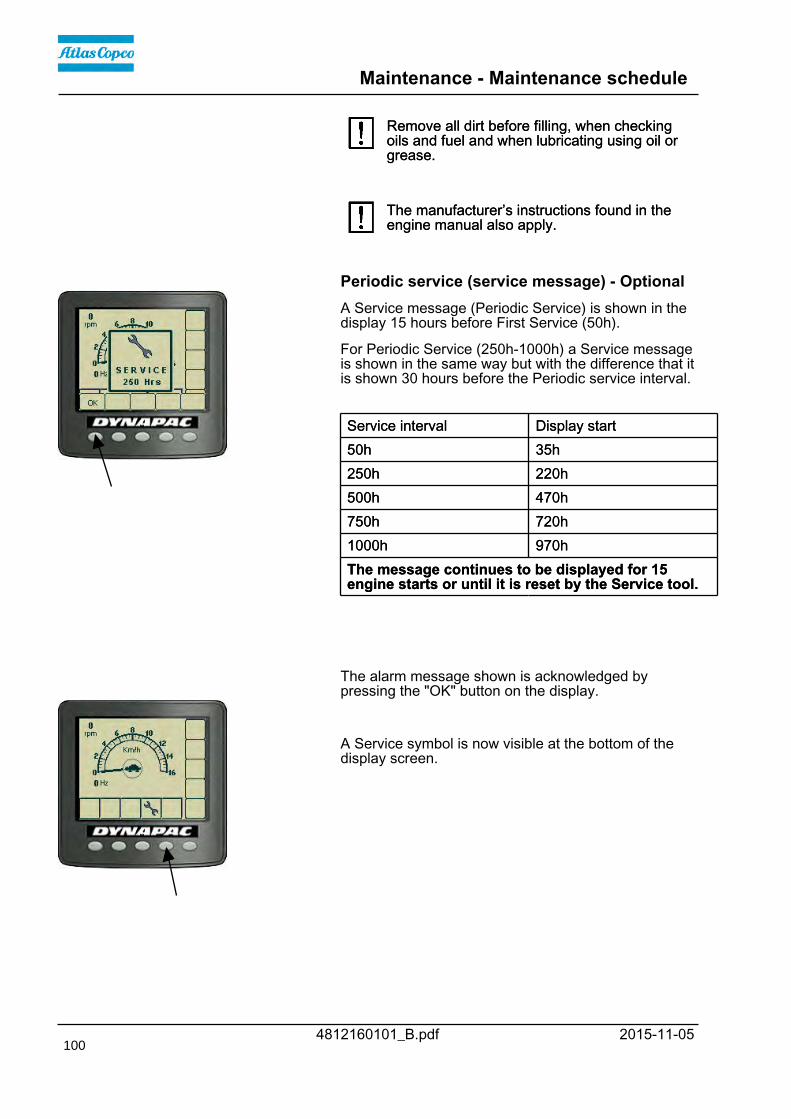
Maintenance - Maintenance schedule
4812160101_B.pdf 2015-11-05
Remove all dirt before filling, when checkingoils and fuel and when lubricating using oil orgrease.
Remove all dirt before filling, when checkingoils and fuel and when lubricating using oil orgrease.
The manufacturer’s instructions found in theengine manual also apply.The manufacturer’s instructions found in theengine manual also apply.
Periodic service (service message) - OptionalA Service message (Periodic Service) is shown in thedisplay 15 hours before First Service (50h).
For Periodic Service (250h-1000h) a Service messageis shown in the same way but with the difference that itis shown 30 hours before the Periodic service interval.
Service interval Display startService interval Display start50h 35h50h 35h250h 220h250h 220h500h 470h500h 470h750h 720h750h 720h1000h 970h1000h 970hThe message continues to be displayed for 15engine starts or until it is reset by the Service tool.The message continues to be displayed for 15engine starts or until it is reset by the Service tool.
The alarm message shown is acknowledged bypressing the "OK" button on the display.
A Service symbol is now visible at the bottom of thedisplay screen.
100

Maintenance - Maintenance schedule
4812160101_B.pdf2015-11-05
Every 10 hours of operation (Daily)Refer to the contents to find the page number of thesections referred to !
Pos. in fig Action CommentPos. in fig Action CommentBefore starting up for the first time on that dayBefore starting up for the first time on that day
14 Check the scraper setting14 Check the scraper settingCheck for free circulation of cooling airCheck for free circulation of cooling air
31 Check coolant level Refer to the engine manual31 Check coolant level Refer to the engine manual2 Check the engine oil level Refer to the engine manual2 Check the engine oil level Refer to the engine manual1 Refuel1 Refuel6 Check fluid level in hydraulic reservoir6 Check fluid level in hydraulic reservoir
Test the brakesTest the brakes
After the FIRST 50 hours of operationRefer to the contents to find the page number of thesections referred to !
Pos. in fig Action CommentPos. in fig Action Comment8 Change the hydraulic fluid filter8 Change the hydraulic fluid filter12 Change the drum cartridge oil12 Change the drum cartridge oil20 Check the wheel-nuts are tightened20 Check the wheel-nuts are tightened21 Check the tire pressure21 Check the tire pressure13 Change the oil in the drum gearbox13 Change the oil in the drum gearbox17 Steering hitch - Tightening17 Steering hitch - Tightening
Every 50 hours of operation (Weekly)Refer to the contents to find the page number of thesections referred to!
Pos.in fig
Action CommentPos.in fig
Action Comment
Check that hoses and couplings are not leakingCheck that hoses and couplings are not leakingCheck DCO cables and connectors in the drumCheck DCO cables and connectors in the drum
101

Maintenance - Maintenance schedule
4812160101_B.pdf 2015-11-05
Every 250 / 750 / 1250 / 1750 hours of operationRefer to the contents to find the page number of thesections referred to !
Pos. in fig Action CommentPos. in fig Action Comment23,22 Check the oil level in rear axle/planetary gears23,22 Check the oil level in rear axle/planetary gears12 Check the oil level in the drum12 Check the oil level in the drum13 Check the oil level in drum gearbox13 Check the oil level in drum gearbox32,31 Clean the coolers32,31 Clean the coolers16 Check rubber elements and bolted joints16 Check rubber elements and bolted joints15 Check batteries15 Check batteries34 Check the AC Optional34 Check the AC Optional
Every 500 / 1500 hours of operationRefer to the contents to find the page number of thesections referred to !
Pos. in fig Action CommentPos. in fig Action Comment4 Inspect the filter element in the air cleaner Replace as required4 Inspect the filter element in the air cleaner Replace as required23,22 Check the oil level in rear axle/planetary gears23,22 Check the oil level in rear axle/planetary gears12 Check the oil level in the drum.12 Check the oil level in the drum.12 Change the oil in the drum gearbox12 Change the oil in the drum gearbox13 Check the oil level in drum gearbox13 Check the oil level in drum gearbox32,31 Clean the coolers32,31 Clean the coolers3 Replace the fuel filter Refer to the engine manual3 Replace the fuel filter Refer to the engine manual3 Replace the fuel pre-filter Refer to the engine manual3 Replace the fuel pre-filter Refer to the engine manual5 Lubricate controls and joints5 Lubricate controls and joints2,25 Change the engine oil and oil filter. * Refer to the engine manual
*) 500h or once every 6months/once a year(Cummins/Deutz).
2,25 Change the engine oil and oil filter. * Refer to the engine manual*) 500h or once every 6months/once a year(Cummins/Deutz).
27,28 Lubricate seat bearing/steering chain Optional27,28 Lubricate seat bearing/steering chain OptionalCheck the engine's valve clearance (after the first500 h)
Refer to the engine manualCheck the engine's valve clearance (after the first500 h)
Refer to the engine manual
102

Maintenance - Maintenance schedule
4812160101_B.pdf2015-11-05
Every 1000 hours of operationRefer to the contents to find the page number of thesections referred to !
Pos. in fig Action CommentPos. in fig Action Comment8 Change the hydraulic fluid filter8 Change the hydraulic fluid filter4 Inspect the filter element in the air cleaner Replace as required4 Inspect the filter element in the air cleaner Replace as required22 Change oil in rear axle differential22 Change oil in rear axle differential23 Change oil in the rear axle planetary gearing23 Change oil in the rear axle planetary gearing12 Check the oil level in the drum.12 Check the oil level in the drum.12 Change the oil in the drum gearbox.12 Change the oil in the drum gearbox.13 Change the oil in drum gearbox13 Change the oil in drum gearbox32,31 Clean the coolers32,31 Clean the coolers3 Replace the fuel filter Refer to the engine manual3 Replace the fuel filter Refer to the engine manual3 Replace the fuel pre-filter Refer to the engine manual3 Replace the fuel pre-filter Refer to the engine manual2,25 Change the engine oil and oil filter. * Refer to the engine manual
*) 500h or once every 6months/once a year(Cummins/Deutz).
2,25 Change the engine oil and oil filter. * Refer to the engine manual*) 500h or once every 6months/once a year(Cummins/Deutz).
7 Check bleeder filter on hydraulic reservoir7 Check bleeder filter on hydraulic reservoir9 Drain the condensate from hydraulic reservoir9 Drain the condensate from hydraulic reservoir26 Drain condensate from fuel tank Optional26 Drain condensate from fuel tank Optional33 Replace the fresh air filter in the cab Optional33 Replace the fresh air filter in the cab Optional19 Check belt tension in the drive belt system Refer to the engine manual19 Check belt tension in the drive belt system Refer to the engine manual17 Steering hitch - Tightening17 Steering hitch - Tightening
103

Maintenance - Maintenance schedule
4812160101_B.pdf 2015-11-05
Every 2000 hours of operationRefer to the contents to find the page number of thesections referred to !
Pos. in fig Action CommentPos. in fig Action Comment6,10 Change the hydraulic fluid6,10 Change the hydraulic fluid8 Change the hydraulic fluid filter8 Change the hydraulic fluid filter4 Inspect the filter element in the air cleaner Replace as required4 Inspect the filter element in the air cleaner Replace as required22 Change oil in rear axle differential22 Change oil in rear axle differential23 Change oil in the rear axle planetary gearing23 Change oil in the rear axle planetary gearing12 Change the oil in the drum12 Change the oil in the drum12 Change the oil in the drum gearbox.12 Change the oil in the drum gearbox.13 Change the oil in the drum gearbox13 Change the oil in the drum gearbox32,31 Clean the coolers32,31 Clean the coolers3 Replace the fuel filter Refer to the engine manual3 Replace the fuel filter Refer to the engine manual3 Replace the fuel pre-filter Refer to the engine manual3 Replace the fuel pre-filter Refer to the engine manual29 Lubricate the Forward/Reverse lever29 Lubricate the Forward/Reverse lever2,25 Change the engine oil and oil filter. * See the engine manual
*) 500 h, or once every 6months/once a year(Cummins/Deutz)
2,25 Change the engine oil and oil filter. * See the engine manual*) 500 h, or once every 6months/once a year(Cummins/Deutz)
27,28 Grease the steering bearing / steering chain Optional27,28 Grease the steering bearing / steering chain Optional7 Check bleeder filter on hydraulic reservoir7 Check bleeder filter on hydraulic reservoir9 Drain the condensate from hydraulic reservoir9 Drain the condensate from hydraulic reservoir26 Drain condensate from fuel tank Optional26 Drain condensate from fuel tank Optional34 Overhaul air conditioning Optional34 Overhaul air conditioning Optional
Check engine's valve clearances Refer to the engine manualCheck engine's valve clearances Refer to the engine manual19 Check belt tension in the drive belt system Refer to the engine manual19 Check belt tension in the drive belt system Refer to the engine manual
Replace ventilation filter in the crankcase ** See engine manual**), only applies toCummins IIIB/T4i
Replace ventilation filter in the crankcase ** See engine manual**), only applies toCummins IIIB/T4i
17 Steering hitch - Tightening17 Steering hitch - Tightening
104

Maintenance - Maintenance schedule
4812160101_B.pdf2015-11-05
Every other yearRefer to the contents to find the page number of thesections referred to !
Pos. in fig Action CommentPos. in fig Action Comment31 Change the coolant (glycol)31 Change the coolant (glycol)10 Change the oil in the hydraulic tank10 Change the oil in the hydraulic tank4 Inspect the filter element in the air cleaner Replace as required4 Inspect the filter element in the air cleaner Replace as required22 Check the oil level in the rear axle's differential22 Check the oil level in the rear axle's differential23 Check oil level in rear axle's planetary gearing23 Check oil level in rear axle's planetary gearing12 Check the oil level in the drum/drum gearbox.12 Check the oil level in the drum/drum gearbox.13 Change the oil in drum gearbox13 Change the oil in drum gearbox16 Check rubber elements and bolted joints16 Check rubber elements and bolted joints9 Drain the condensate from hydraulic reservoir9 Drain the condensate from hydraulic reservoir26 Drain condensate from fuel tank Optional26 Drain condensate from fuel tank Optional19 Check belt tension in the drive belt system Refer to the engine manual19 Check belt tension in the drive belt system Refer to the engine manual
105

Maintenance - Maintenance schedule
4812160101_B.pdf 2015-11-05106

Maintenance, 10h
4812160101_B.pdf2015-11-05
Maintenance, 10h
Park the roller on a level surface.The engine must be switched off and theparking brake activated when checking oradjusting the roller, unless otherwise specified.
Park the roller on a level surface.The engine must be switched off and theparking brake activated when checking oradjusting the roller, unless otherwise specified.
Ensure that there is good ventilation (airextraction) if the engine is run indoors. Risk ofcarbon monoxide poisoning.
Ensure that there is good ventilation (airextraction) if the engine is run indoors. Risk ofcarbon monoxide poisoning.
Scrapers - Check, adjustmentIt is important to consider movement of the drumwhen the machine turns, i.e., the scrapers can bedamaged or wear of the drum may increase ifadjustment is made closer than the values stated.
It is important to consider movement of the drumwhen the machine turns, i.e., the scrapers can bedamaged or wear of the drum may increase ifadjustment is made closer than the values stated.
Fig. Scrapers1. Scraper blade (x 4)2. Screws
12
If necessary, adjust distance to the drum as follows:
Loosen the screws (2) on the scraper attachment.
Then adjust the scraper blade (1) to 25 mm (1 in) fromthe drum.
Tighten the screws (2).
Repeat the procedure for the other scraper blades (x4).
107

Maintenance, 10h
4812160101_B.pdf 2015-11-05
Air circulation - Check
Fig. Engine hood 1. Hood lock 2. Protective grille
1
2 Ensure that the engine has free circulation of coolingair through the protective grille in the hood.
To open the engine hood, turn the lock handle (1)upward. Raise the hood to its fully open position,checking that the red safety catch on the left gasspring is latched.
If the gas-springs for the hood are loosend and thehood is raised to its upper position - block thehood so that it cannot fall.
If the gas-springs for the hood are loosend and thehood is raised to its upper position - block thehood so that it cannot fall.
Coolant level - Check
Fig. Expansion tank 1. Filler cap 2. Sight glass
1
2
Place the roller on a flat surface and check the level ofthe coolant in the sight glass (2). Top up with coolant ifthe level is too low.
Take great caution if the radiator cap must beopened while the engine is hot. Wear protectivegloves and goggles.
Take great caution if the radiator cap must beopened while the engine is hot. Wear protectivegloves and goggles.
Fill with a mixture of 50% water and 50% anti freeze.See the lubrication specifications in these instructionsand in the engine manual.
Flush the system every other year and changethe coolant. Make sure also that the air flowthrough the cooler is unobstructed.
Flush the system every other year and changethe coolant. Make sure also that the air flowthrough the cooler is unobstructed.
108

Maintenance, 10h
4812160101_B.pdf2015-11-05
Diesel engine Check oil level
Fig. Engine compartment 1. Dipstick
1
Take care not to touch any hot parts of the engineor the radiator when removing the dipstick. Riskfor burns.
Take care not to touch any hot parts of the engineor the radiator when removing the dipstick. Riskfor burns.
The dipstick is located beside the engine's oil and fuelfilter.
Pull up the dipstick (1) and check that the oil level isbetween the upper and lower marks. For furtherdetails, refer to the engine's instruction manual.
Fuel tank - Filling
Fig. Fuel tank 1. Filler pipe
1
Top up the fuel tank every day. Follow the enginemanufacturer's specifications for diesel fuel.
The new Tier 4i/Stage IIIB Cummins enginesrequire the use of Ultra Low Sulphur Diesel(ULSD) fuel, which has a sulphur content of 15ppm (parts per million) or less. A higher sulphurcontent will cause operating problems and put theuseful life of components at risk, which can leadto engine trouble.
The new Tier 4i/Stage IIIB Cummins enginesrequire the use of Ultra Low Sulphur Diesel(ULSD) fuel, which has a sulphur content of 15ppm (parts per million) or less. A higher sulphurcontent will cause operating problems and put theuseful life of components at risk, which can leadto engine trouble.
Stop the engine. Short-circuit (press) the filler gunagainst a non-insulated part of the roller beforerefuelling, and against the filler pipe (1) whilerefuelling.
Stop the engine. Short-circuit (press) the filler gunagainst a non-insulated part of the roller beforerefuelling, and against the filler pipe (1) whilerefuelling.
Never refuel while the engine is running. Do notsmoke and avoid spilling fuel.Never refuel while the engine is running. Do notsmoke and avoid spilling fuel.
109

Maintenance, 10h
4812160101_B.pdf 2015-11-05
Hydraulic reservoir - Check fluid level
Fig. Hydraulic reservoir 1. Sight glass 2. Filler pipe
1
2
Place the roller on a level surface and check that theoil level in the sight glass (1) is between the max andmin markings.
Top up with the type of hydraulic fluid specified in thelubricant specification, if the level is too low.
The volume between the min. and max. lines isapprox. 4 liters (4.2 qts).
110
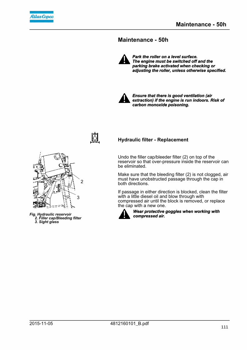
Maintenance - 50h
4812160101_B.pdf2015-11-05
Maintenance - 50h
Park the roller on a level surface.The engine must be switched off and theparking brake activated when checking oradjusting the roller, unless otherwise specified.
Park the roller on a level surface.The engine must be switched off and theparking brake activated when checking oradjusting the roller, unless otherwise specified.
Ensure that there is good ventilation (airextraction) if the engine is run indoors. Risk ofcarbon monoxide poisoning.
Ensure that there is good ventilation (airextraction) if the engine is run indoors. Risk ofcarbon monoxide poisoning.
Hydraulic filter - Replacement
Fig. Hydraulic reservoir 2. Filler cap/Bleeding filter 3. Sight glass
2
3
Undo the filler cap/bleeder filter (2) on top of thereservoir so that over-pressure inside the reservoir canbe eliminated.
Make sure that the bleeding filter (2) is not clogged, airmust have unobstructed passage through the cap inboth directions.
If passage in either direction is blocked, clean the filterwith a little diesel oil and blow through withcompressed air until the block is removed, or replacethe cap with a new one.
Wear protective goggles when working withcompressed air.Wear protective goggles when working withcompressed air.
111

Maintenance - 50h
4812160101_B.pdf 2015-11-05
Clean thoroughly around the oil filter.
Fig. Engine compartment 1. Hydraulic fluid filter (x1).
1
Remove the oil filter (1) and hand in to anenvironment-friendly waste disposal station. Thisis a single-use filter and cannot be cleaned.
Remove the oil filter (1) and hand in to anenvironment-friendly waste disposal station. Thisis a single-use filter and cannot be cleaned.
Make sure that the old sealing ring is not left onthe filter holder, Otherwise, this could causeleakage between the new seal and the old one.
Make sure that the old sealing ring is not left onthe filter holder, Otherwise, this could causeleakage between the new seal and the old one.
Thoroughly clean the filter holder's sealing surfaces.
Apply a thin coat of fresh hydraulic fluid on the newfilter seal. Screw tight the filter by hand.
First tighten the filter until its seal is in contactwith the filter attachment. Then turn an additionalhalf revolution. Do not tighten the filter too hardas this could damage the gasket.
First tighten the filter until its seal is in contactwith the filter attachment. Then turn an additionalhalf revolution. Do not tighten the filter too hardas this could damage the gasket.
Start the engine and check that there is no leakage ofhydraulic fluid from the filter. Check level of fluid in thesight glass (3) and top up as required.
Ensue that there is good ventilation (air extraction)if the engine is run indoors. Risk of carbonmonoxide poisoning.
Ensue that there is good ventilation (air extraction)if the engine is run indoors. Risk of carbonmonoxide poisoning.
112

Maintenance - 50h
4812160101_B.pdf2015-11-05
Tires - Air pressure - Wheel nuts - Tightening
Fig. Wheels1. Air valve2. Wheel nut
12
Check the tire pressures using a pressure gauge.
If the tires are filled with fluid, the air valve (1) must bein the "12 o'clock" position during pumping.
Recommended pressure: See TechnicalSpecifications.
Check the tire pressure.When changing the tires it is important that bothof them have the same rolling radius. This isnecessary to ensure proper functioning of theanti-slip in the rear axle.
When changing the tires it is important that bothof them have the same rolling radius. This isnecessary to ensure proper functioning of theanti-slip in the rear axle.
Check the tightening torque of the wheel nuts (2) at630 Nm (465 lbf.ft).
Check both wheels and all nuts. (This only applies to anew machine or newly fitted wheels).
Check the safety manual that accompanies theroller before filling the tires with air.Check the safety manual that accompanies theroller before filling the tires with air.
Drum gearbox - Oil change
Fig. Drum gearbox 1. Drain plug 2. Filler plug 3. Level plug
1
2
3
Wipe clean, unscrew the plugs (1, 2 and 3) and drainthe oil into a suitable receptacle, capacity about 5.0liters (5,3 qts.).
Refit the drain plug (1) and fill with oil up to the levelplug (3), according to "Drum gearbox - Checking theoil level".
Use transmission oil according to the lubricantspecification.
Clean and refit the level plug (3) and filler plug (2).
113

Maintenance - 50h
4812160101_B.pdf 2015-11-05
Steering hitch - Tightening
Fig. Steering hitch 1. Nut
1
Nobody must be allowed near the steering jointwhen the engine is running. Risk of beingcrushed when the steering is operated. Switchoff the engine and activate the parking brakebefore lubricating.
Nobody must be allowed near the steering jointwhen the engine is running. Risk of beingcrushed when the steering is operated. Switchoff the engine and activate the parking brakebefore lubricating.
The easiest way to identify if you have this type ofsteering hitch is that it has a new type of nut (1) at thetop, as shown.
Actual torque (Nm) should be when the machine'sposition is straight ahead.M14 174 NmM14 174 NmM16 270 NmM16 270 Nm
114

Maintenance - 50h
4812160101_B.pdf2015-11-05
Maintenance - 50h
Park the roller on a level surface.The engine must be switched off and theparking brake activated when checking oradjusting the roller, unless otherwise specified.
Park the roller on a level surface.The engine must be switched off and theparking brake activated when checking oradjusting the roller, unless otherwise specified.
Ensure that there is good ventilation (airextraction) if the engine is run indoors. Risk ofcarbon monoxide poisoning.
Ensure that there is good ventilation (airextraction) if the engine is run indoors. Risk ofcarbon monoxide poisoning.
Air cleaner- Check hoses and connections
Check that the hose clamps between the filterhousing and the suction hose are tight and thatthe hoses are intact. Inspect the entire hosesystem, all the way to the engine.
Check that the hose clamps between the filterhousing and the suction hose are tight and thatthe hoses are intact. Inspect the entire hosesystem, all the way to the engine.
Replace if necessary, as damage to hoses/hoseclamps can seriously damage the engine
Drum - Oil change
Fig. Left drum side 1. Groove
1 NOTE: This 50 hour oil change only applies to a newmachine, or after renovation of the drum.
Position the roller on a flat surface with the groove (1)on the inside of the drum aligned with the top of thedrum frame.
115

Maintenance - 50h
4812160101_B.pdf 2015-11-05
Fig. Drum, right side 1. Filler plug 2. Level glass 3. Drain plug
1
2
3
Drum - Oil changeEnsure that the drum's plugs and level glass arepositioned as in Fig 2.
Place a vessel capable of holding at least 20 liters (5.3gal) under drain plug (3).
Remove and clean filler plug (1) and drain plug (3).
Allow all the oil to drain out. Clean and refit drain plug(3) and fill with new synthetic oil. The total volume ofoil in the drum must be 15 liters (4.0 gal).
Deliver the drain oil to environmentally correcthandling.Deliver the drain oil to environmentally correcthandling.
Make sure to only use Dynapac Drum Oil 1000 inthe drum.Make sure to only use Dynapac Drum Oil 1000 inthe drum.
Clean and refit filler plug (1).
116

Maintenance - 50h
4812160101_B.pdf2015-11-05
Fig. Gearbox - Drum, right side 1. Filler plug/Level plug 2. Drain plug
1
2
Gearbox - Oil changePlace the roller on a level surface.
Place a receptacle that holds at least 1 liter (0.3 gal))under the drain plug (2).
Unscrew and clean the filler/level plug (1) and thedrain plug (2).
Allow all of the oil to drain off. Clean and refit drainplug (2) and fill with oil up to filler/level plug (1). Thetotal volume of oil in the gearbox must be 0.3 liters(0.08 gal).
Deliver the drain oil to environmentally correcthandling.Deliver the drain oil to environmentally correcthandling.
Make sure to only use Dynapac Drum Oil 1000 inthe gearbox.Make sure to only use Dynapac Drum Oil 1000 inthe gearbox.
Clean and refit filler/level plug (1).
117

Maintenance - 50h
4812160101_B.pdf 2015-11-05118

Maintenance - 250 / 750 / 1250 / 1750h
4812160101_B.pdf2015-11-05
Maintenance - 250 / 750 / 1250 / 1750hPark the roller on a level surface.The engine must be switched off and theparking brake activated when checking oradjusting the roller, unless otherwise specified.
Park the roller on a level surface.The engine must be switched off and theparking brake activated when checking oradjusting the roller, unless otherwise specified.
Ensure that there is good ventilation (airextraction) if the engine is run indoors. Risk ofcarbon monoxide poisoning.
Ensure that there is good ventilation (airextraction) if the engine is run indoors. Risk ofcarbon monoxide poisoning.
Rear axle differential - Check oil level
Fig. Level control - differential housing 1. Level plugs (x 3) 2. Filler plug
1
21
Never work under the roller when the engine isrunning. Park on a level surface. Block the wheelssecurely.
Never work under the roller when the engine isrunning. Park on a level surface. Block the wheelssecurely.
Wipe clean and remove the level plugs (1) and checkthat the oil level reaches the lower edge of the plugholes. The plugs can be found at the front or rear ofthe rear axle.
At a low level, remove the filler plug (2) and top upwith oil to the correct level. Use transmission oil, seelubricant specifications.
Clean and refit the plug.
119

Maintenance - 250 / 750 / 1250 / 1750h
4812160101_B.pdf 2015-11-05
Rear axle planetary gears - Check oil level
Fig. Level check - planetary gear 1. Level/Filler plug
1
Position the roller so that the level plug (1) in theplanetary gear is at "9 o'clock" or "3 o'clock".
Wipe clean and remove the level plug (1) and checkthat the oil level reaches the lower edge of the plughole. Top off with oil to the right level if the level is low.Use transmission oil. See lubrication specification.
Clean and refit the plug.
Check the fluid level in the same way on the rearaxle's other planetary gear.
Drum - Checking the oil level
Fig. Left drum side 1. Groove
1 Position the roller on a flat surface with the groove (1)on the inside of the drum aligned with the top of thedrum frame.
120

Maintenance - 250 / 750 / 1250 / 1750h
4812160101_B.pdf2015-11-05
The oil should now come up to the sight glass (2).
Fig. Drum, right side 1. Filler plug 2. Level glass
1
2
If necessary, release the filler plug (1) and fill to halfthe sight glass (2).
Do not overfill with oil - risk of overheating.Do not overfill with oil - risk of overheating.
Make sure to only use Dynapac Drum Oil 1000 inthe drum.Make sure to only use Dynapac Drum Oil 1000 inthe drum.
Clean and refit filler plug (1).
Gearbox - Checking the oil level
Fig. Gearbox - Drum, right side 1. Filler/Level plug 2. Drain plug
1
2
Park the roller on flat ground.
Clean and dry around filler/level plug (1) and unscrewthe plug.
Check that the oil is level with the bottom edge of theplug hole.
If the oil is too low, fill until the oil reaches filler/levelplug (1).
Overfilling with oil can cause overheating.Overfilling with oil can cause overheating.
Make sure to only use Dynapac Drum Oil 1000 inthe gearbox.Make sure to only use Dynapac Drum Oil 1000 inthe gearbox.
Clean and refit filler/level plug (1).
121

Maintenance - 250 / 750 / 1250 / 1750h
4812160101_B.pdf 2015-11-05
Drum gearbox - Checking the oil level
Fig. Oil level check - drum gearbox 1. Level plug 2. Filler plug 3. Drain plug
1
2
3
Wipe clean the area around the level plug (1) and thenundo the plug.
Ensure that the oil level reaches up to the lower edgeof the plug hole.
Top off with oil to the right level if the level is low. Usetransmission oil according to the lubricant specification.
Clean and refit the plugs.
Radiator - Check/Cleaning
Fig. Engine compartment 1. Water cooler 2. Charge air cooler 3. Hydraulic fluid cooler 4. Condenser element AC (Optional) 5. Screws (x 2)
1
2
345
5 Check that air can pass unobstructed through theradiators (1), (2) and (3).
Clean a dirty radiator using compressed air or ahigh-pressure water jet.
Undo the two screws (5) and tilt the condenserelement upwards.
Blow air or direct water through the cooler in theopposite direction to that of the cooling air.
Be careful when using a high-pressure washer -do not place the nozzle too close to the radiator.Be careful when using a high-pressure washer -do not place the nozzle too close to the radiator.
Wear protective goggles when working withcompressed air or high-pressure water jets.Wear protective goggles when working withcompressed air or high-pressure water jets.
122
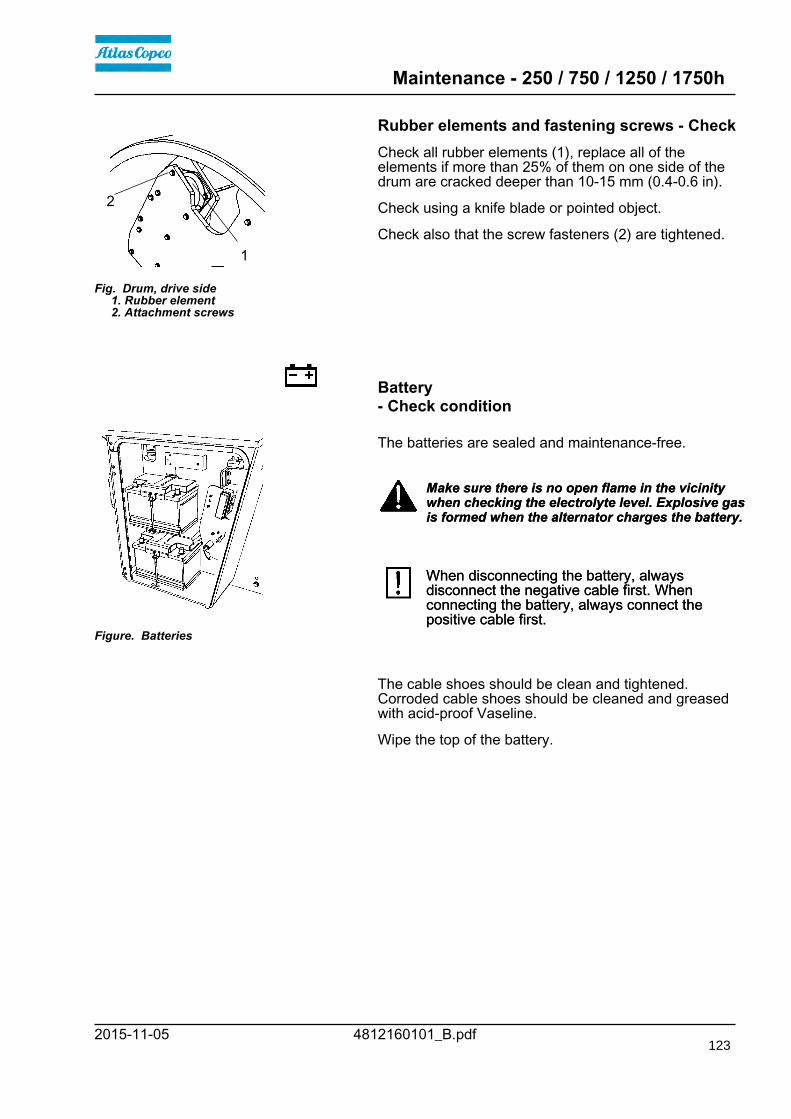
Maintenance - 250 / 750 / 1250 / 1750h
4812160101_B.pdf2015-11-05
Rubber elements and fastening screws - Check
Fig. Drum, drive side 1. Rubber element 2. Attachment screws
1
2
Check all rubber elements (1), replace all of theelements if more than 25% of them on one side of thedrum are cracked deeper than 10-15 mm (0.4-0.6 in).
Check using a knife blade or pointed object.
Check also that the screw fasteners (2) are tightened.
Battery- Check condition
Figure. Batteries
The batteries are sealed and maintenance-free.
Make sure there is no open flame in the vicinitywhen checking the electrolyte level. Explosive gasis formed when the alternator charges the battery.
Make sure there is no open flame in the vicinitywhen checking the electrolyte level. Explosive gasis formed when the alternator charges the battery.
When disconnecting the battery, alwaysdisconnect the negative cable first. Whenconnecting the battery, always connect thepositive cable first.
When disconnecting the battery, alwaysdisconnect the negative cable first. Whenconnecting the battery, always connect thepositive cable first.
The cable shoes should be clean and tightened.Corroded cable shoes should be cleaned and greasedwith acid-proof Vaseline.
Wipe the top of the battery.
123

Maintenance - 250 / 750 / 1250 / 1750h
4812160101_B.pdf 2015-11-05
Air conditioning (Optional)- Inspection
Fig. Air conditioning 1. Refrigerant hoses 2. Condensor element
1
2 Inspect refrigerant hoses and connections and makesure that there are no signs of an oil film that canindicate a refrigerant leakage.
The refrigerant contains tracing liquid, which makes itpossible to detect leaks with the aid of a UV lamp. Ifthe areas around the connections are stronglycoloured, this is an indication of a leak.
Automatic Climate Control (Optional) -Inspection
Fig. Drying filter 1. Sight glass
1
With the unit in operation, open the engine hood andcheck using the sight glass (1) that bubbles are notvisible on the drying filter.
The filter is located on the right-hand side at the frontedge of the engine compartment. If bubbles are visiblethrough the sight glass, this is a sign that therefrigerant level is too low. If so, stop the unit. The unitmay be damaged if it is run with insufficient refrigerant.
Fig. Engine compartment 1. Condenser element 2. Drying filter 3. Screws (x 2)
1
2
3
3 If there is a significant loss of cooling capacity, cleanthe condenser element (1) located above the coolersin the engine compartment.
Undo the two screws (3) and tilt the condenserelement (1) upwards.
Also clean the cooling unit in the cab. See under theheading 2000 hours, air conditioning - overhaul.
124

Maintenance - 500 / 1500h
4812160101_B.pdf2015-11-05
Maintenance - 500 / 1500h
Park the roller on a level surface.The engine must be switched off and theparking brake activated when checking oradjusting the roller, unless otherwise specified.
Park the roller on a level surface.The engine must be switched off and theparking brake activated when checking oradjusting the roller, unless otherwise specified.
Ensure that there is good ventilation (airextraction) if the engine is run indoors. Risk ofcarbon monoxide poisoning.
Ensure that there is good ventilation (airextraction) if the engine is run indoors. Risk ofcarbon monoxide poisoning.
Air cleanerChecking - Change the main air filter
Change the air cleaner's main filter when thewarning lamp on the display lights when thediesel engine is operating at full speed.
Change the air cleaner's main filter when thewarning lamp on the display lights when thediesel engine is operating at full speed.
3
6 4 5
2
Fig. Air cleaner 1. Clips 2. Cover 3. Main filter 4. Backup filter 5. Filter housing 6. Dust valve
1
Release the clips (1), pull off the cover (2), and pull outthe main filter (3).
Do not remove the backup filter (4).
Clean the air cleaner if necessary, see section Aircleaner - Cleaning.
When replacing the main filter (3), insert a new filterand refit the air cleaner in the reverse order.
Check the condition of the dust valve (6); replace ifnecessary.
When refitting the cover, make sure that the dust valveis positioned downwards.
125

Maintenance - 500 / 1500h
4812160101_B.pdf 2015-11-05
Backup filter - Change
Fig. Air filter 1. Backup filter
1 Change the backup filter with a new filter after everysecond replacement of the main filter.
To change the backup filter (1), pull the old filter out ofits holder, insert a new filter and reassemble the aircleaner in the reverse order.
Clean the air cleaner if necessary, see section Aircleaner - Cleaning.
Air cleaner- Cleaning
Wipe clean on both sides of the outletpipe.
Outer edge of outletpipe.
Inner edge ofoutlet pipe.
Wipe clean the inside of the cover (2) and the filterhousing (5). See the previous illustration.
Wipe also both surfaces for the outlet pipe; seeadjacent figure.
Check that the hose clamps between the filterhousing and the suction hose are tight and thatthe hoses are intact. Inspect the entire hosesystem, all the way to the engine.
Check that the hose clamps between the filterhousing and the suction hose are tight and thatthe hoses are intact. Inspect the entire hosesystem, all the way to the engine.
126

Maintenance - 500 / 1500h
4812160101_B.pdf2015-11-05
Rear axle differential - Check oil level
Fig. Level control - differential housing 1. Level plugs (x 3) 2. Filler plug
1
21
Never work under the roller when the engine isrunning. Park on a level surface. Block the wheelssecurely.
Never work under the roller when the engine isrunning. Park on a level surface. Block the wheelssecurely.
Wipe clean and remove the level plugs (1) and checkthat the oil level reaches the lower edge of the plugholes. The plugs can be found at the front or rear ofthe rear axle.
At a low level, remove the filler plug (2) and top upwith oil to the correct level. Use transmission oil, seelubricant specifications.
Clean and refit the plug.
Rear axle planetary gears - Check oil level
Fig. Level check - planetary gear 1. Level/Filler plug
1
Position the roller so that the level plug (1) in theplanetary gear is at "9 o'clock" or "3 o'clock".
Wipe clean and remove the level plug (1) and checkthat the oil level reaches the lower edge of the plughole. Top off with oil to the right level if the level is low.Use transmission oil. See lubrication specification.
Clean and refit the plug.
Check the fluid level in the same way on the rearaxle's other planetary gear.
127

Maintenance - 500 / 1500h
4812160101_B.pdf 2015-11-05
Drum - Checking the oil level
Fig. Left drum side 1. Groove
1 Position the roller on a flat surface with the groove (1)on the inside of the drum aligned with the top of thedrum frame.
The oil should now come up to the sight glass (2).
Fig. Drum, right side 1. Filler plug 2. Level glass
1
2
If necessary, release the filler plug (1) and fill to halfthe sight glass (2).
Do not overfill with oil - risk of overheating.Do not overfill with oil - risk of overheating.
Make sure to only use Dynapac Drum Oil 1000 inthe drum.Make sure to only use Dynapac Drum Oil 1000 inthe drum.
Clean and refit filler plug (1).
128
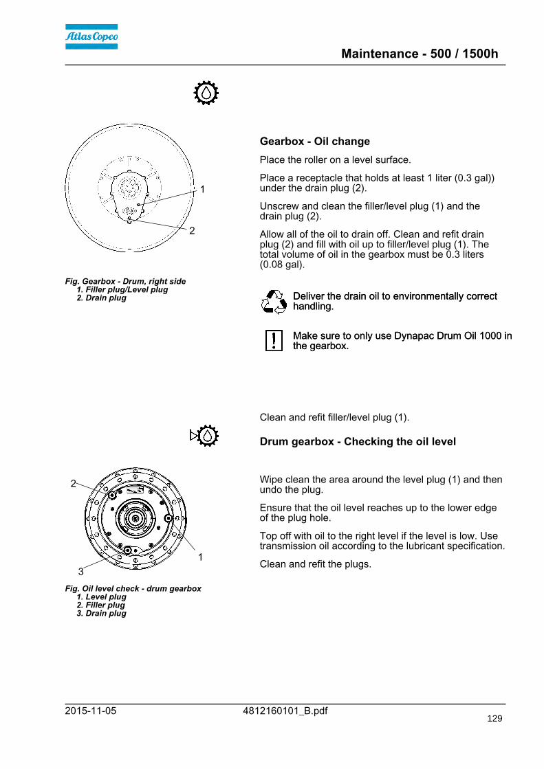
Maintenance - 500 / 1500h
4812160101_B.pdf2015-11-05
Fig. Gearbox - Drum, right side 1. Filler plug/Level plug 2. Drain plug
1
2
Gearbox - Oil changePlace the roller on a level surface.
Place a receptacle that holds at least 1 liter (0.3 gal))under the drain plug (2).
Unscrew and clean the filler/level plug (1) and thedrain plug (2).
Allow all of the oil to drain off. Clean and refit drainplug (2) and fill with oil up to filler/level plug (1). Thetotal volume of oil in the gearbox must be 0.3 liters(0.08 gal).
Deliver the drain oil to environmentally correcthandling.Deliver the drain oil to environmentally correcthandling.
Make sure to only use Dynapac Drum Oil 1000 inthe gearbox.Make sure to only use Dynapac Drum Oil 1000 inthe gearbox.
Clean and refit filler/level plug (1).
Drum gearbox - Checking the oil level
Fig. Oil level check - drum gearbox 1. Level plug 2. Filler plug 3. Drain plug
1
2
3
Wipe clean the area around the level plug (1) and thenundo the plug.
Ensure that the oil level reaches up to the lower edgeof the plug hole.
Top off with oil to the right level if the level is low. Usetransmission oil according to the lubricant specification.
Clean and refit the plugs.
129

Maintenance - 500 / 1500h
4812160101_B.pdf 2015-11-05
Radiator - Check/Cleaning
Fig. Engine compartment 1. Water cooler 2. Charge air cooler 3. Hydraulic fluid cooler 4. Condenser element AC (Optional) 5. Screws (x 2)
1
2
345
5 Check that air can pass unobstructed through theradiators (1), (2) and (3).
Clean a dirty radiator using compressed air or ahigh-pressure water jet.
Undo the two screws (5) and tilt the condenserelement upwards.
Blow air or direct water through the cooler in theopposite direction to that of the cooling air.
Be careful when using a high-pressure washer -do not place the nozzle too close to the radiator.Be careful when using a high-pressure washer -do not place the nozzle too close to the radiator.
Wear protective goggles when working withcompressed air or high-pressure water jets.Wear protective goggles when working withcompressed air or high-pressure water jets.
Fuel pre-filter - Replacement
Fig. Engine compartment 1. Fuel prefilter
1
Ensure good ventilation (air extraction) if thediesel engine is run indoors. Risk of carbonmonoxide poisoning.
Ensure good ventilation (air extraction) if thediesel engine is run indoors. Risk of carbonmonoxide poisoning.
See the engine's instruction manual for filterreplacement, in the Fuel system chapter.
130

Maintenance - 500 / 1500h
4812160101_B.pdf2015-11-05
Replacing the fuel filter
Fig. Engine compartment 1. Fuel filter
1
Place a container underneath to collect fuel that runsout when the filter is released.
Screw off the fuel filter (1). The filter is of thedisposable type and cannot be cleaned. Han in toenvironment-friendly station.
Deliver the drain oil to environmentally correcthandling.Deliver the drain oil to environmentally correcthandling.
Refer to the engine manual for detailedinstructions when replacing the fuel filter.Refer to the engine manual for detailedinstructions when replacing the fuel filter.
Start the engine and check that the fuel filter is tight.
Ensure good ventilation (air extraction) if thediesel engine is run indoors. Risk of carbonmonoxide poisoning.
Ensure good ventilation (air extraction) if thediesel engine is run indoors. Risk of carbonmonoxide poisoning.
NOTE! The new fuel filters must not under anycircumstances be pre-filled with fuel due to the purityrequirements of the fuel system.@@
131
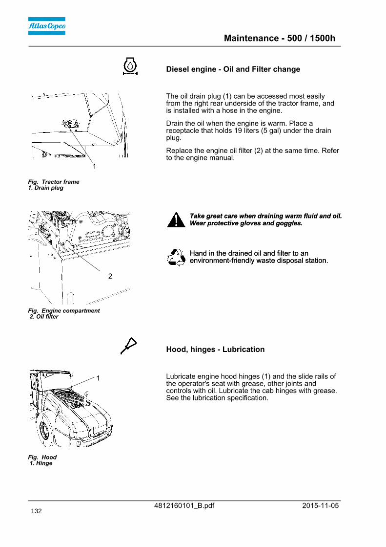
Maintenance - 500 / 1500h
4812160101_B.pdf 2015-11-05
Diesel engine - Oil and Filter change
Fig. Tractor frame1. Drain plug
1
The oil drain plug (1) can be accessed most easilyfrom the right rear underside of the tractor frame, andis installed with a hose in the engine.
Drain the oil when the engine is warm. Place areceptacle that holds 19 liters (5 gal) under the drainplug.
Replace the engine oil filter (2) at the same time. Referto the engine manual.
Fig. Engine compartment 2. Oil filter
2
Take great care when draining warm fluid and oil.Wear protective gloves and goggles.Take great care when draining warm fluid and oil.Wear protective gloves and goggles.
Hand in the drained oil and filter to anenvironment-friendly waste disposal station.Hand in the drained oil and filter to anenvironment-friendly waste disposal station.
Hood, hinges - Lubrication
Fig. Hood 1. Hinge
1 Lubricate engine hood hinges (1) and the slide rails ofthe operator's seat with grease, other joints andcontrols with oil. Lubricate the cab hinges with grease.See the lubrication specification.
132

Maintenance - 500 / 1500h
4812160101_B.pdf2015-11-05
Seat bearing - Lubrication
2
3
1
6
4
Figure. Seat bearing 1. Grease nipple 2. Gearwheel 3. Steering chain 4. Adjusting screw 5. Cover 6. Slide rails 7. Marking
7
5 Keep in mind that the chain is a vital part of thesteering mechanism.Keep in mind that the chain is a vital part of thesteering mechanism.
Remove the cover (5) to access the lubrication nipple(1). Lubricate the operator seat slew bearing with threestrokes of a hand-operated grease gun.
Clean and grease the chain (3) between the seat andthe steering column.
Also grease the seat slide rails (6).
If the chain is slack on the sprocket (2), loosen thescrews (4) and move the steering column forward.Tighten the screws and check chain tension.
No not tension the chain too tightly. It should bepossible to move the chain about 10 mm (0.4 in) to theside with a forefinger/thumb at the marking (7) in seatframe. Fit the chain lock at the bottom.
If the seat starts to be stiff when adjusting, itshould be lubricated more often than specifiedhere.
If the seat starts to be stiff when adjusting, itshould be lubricated more often than specifiedhere.
133

Maintenance - 500 / 1500h
4812160101_B.pdf 2015-11-05134

Maintenance - 1000h
4812160101_B.pdf2015-11-05
Maintenance - 1000h
Park the roller on a level surface.The engine must be switched off and theparking brake activated when checking oradjusting the roller, unless otherwise specified.
Park the roller on a level surface.The engine must be switched off and theparking brake activated when checking oradjusting the roller, unless otherwise specified.
Ensure that there is good ventilation (airextraction) if the engine is run indoors. Risk ofcarbon monoxide poisoning.
Ensure that there is good ventilation (airextraction) if the engine is run indoors. Risk ofcarbon monoxide poisoning.
Hydraulic filter - Replacement
Fig. Hydraulic reservoir 2. Filler cap/Bleeding filter 3. Sight glass
2
3
Undo the filler cap/bleeder filter (2) on top of thereservoir so that over-pressure inside the reservoir canbe eliminated.
Make sure that the bleeding filter (2) is not clogged, airmust have unobstructed passage through the cap inboth directions.
If passage in either direction is blocked, clean the filterwith a little diesel oil and blow through withcompressed air until the block is removed, or replacethe cap with a new one.
Wear protective goggles when working withcompressed air.Wear protective goggles when working withcompressed air.
135

Maintenance - 1000h
4812160101_B.pdf 2015-11-05
Clean thoroughly around the oil filter.
Fig. Engine compartment 1. Hydraulic fluid filter (x1).
1
Remove the oil filter (1) and hand in to anenvironment-friendly waste disposal station. Thisis a single-use filter and cannot be cleaned.
Remove the oil filter (1) and hand in to anenvironment-friendly waste disposal station. Thisis a single-use filter and cannot be cleaned.
Make sure that the old sealing ring is not left onthe filter holder, Otherwise, this could causeleakage between the new seal and the old one.
Make sure that the old sealing ring is not left onthe filter holder, Otherwise, this could causeleakage between the new seal and the old one.
Thoroughly clean the filter holder's sealing surfaces.
Apply a thin coat of fresh hydraulic fluid on the newfilter seal. Screw tight the filter by hand.
First tighten the filter until its seal is in contactwith the filter attachment. Then turn an additionalhalf revolution. Do not tighten the filter too hardas this could damage the gasket.
First tighten the filter until its seal is in contactwith the filter attachment. Then turn an additionalhalf revolution. Do not tighten the filter too hardas this could damage the gasket.
Start the engine and check that there is no leakage ofhydraulic fluid from the filter. Check level of fluid in thesight glass (3) and top up as required.
Ensue that there is good ventilation (air extraction)if the engine is run indoors. Risk of carbonmonoxide poisoning.
Ensue that there is good ventilation (air extraction)if the engine is run indoors. Risk of carbonmonoxide poisoning.
Air cleanerChecking - Change the main air filter
Change the air cleaner's main filter when thewarning lamp on the display lights when thediesel engine is operating at full speed.
Change the air cleaner's main filter when thewarning lamp on the display lights when thediesel engine is operating at full speed.
136

Maintenance - 1000h
4812160101_B.pdf2015-11-05
3
6 4 5
2
Fig. Air cleaner 1. Clips 2. Cover 3. Main filter 4. Backup filter 5. Filter housing 6. Dust valve
1
Release the clips (1), pull off the cover (2), and pull outthe main filter (3).
Do not remove the backup filter (4).
Clean the air cleaner if necessary, see section Aircleaner - Cleaning.
When replacing the main filter (3), insert a new filterand refit the air cleaner in the reverse order.
Check the condition of the dust valve (6); replace ifnecessary.
When refitting the cover, make sure that the dust valveis positioned downwards.
Backup filter - Change
Fig. Air filter 1. Backup filter
1 Change the backup filter with a new filter after everysecond replacement of the main filter.
To change the backup filter (1), pull the old filter out ofits holder, insert a new filter and reassemble the aircleaner in the reverse order.
Clean the air cleaner if necessary, see section Aircleaner - Cleaning.
137

Maintenance - 1000h
4812160101_B.pdf 2015-11-05
Air cleaner- Cleaning
Wipe clean on both sides of the outletpipe.
Outer edge of outletpipe.
Inner edge ofoutlet pipe.
Wipe clean the inside of the cover (2) and the filterhousing (5). See the previous illustration.
Wipe also both surfaces for the outlet pipe; seeadjacent figure.
Check that the hose clamps between the filterhousing and the suction hose are tight and thatthe hoses are intact. Inspect the entire hosesystem, all the way to the engine.
Check that the hose clamps between the filterhousing and the suction hose are tight and thatthe hoses are intact. Inspect the entire hosesystem, all the way to the engine.
138
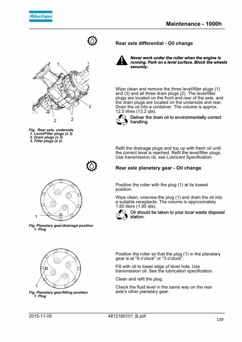
Maintenance - 1000h
4812160101_B.pdf2015-11-05
Rear axle differential - Oil change
Fig. Rear axle, underside 1. Level/Filler plugs (x 3) 2. Drain plugs (x 3) 3. Filler plugs (x x)
3
1
22
Never work under the roller when the engine isrunning. Park on a level surface. Block the wheelssecurely.
Never work under the roller when the engine isrunning. Park on a level surface. Block the wheelssecurely.
Wipe clean and remove the three level/filler plugs (1)and (3) and all three drain plugs (2). The level/fillerplugs are located on the front and rear of the axle, andthe drain plugs are located on the underside and rear.Drain the oil into a container. The volume is approx.12.5 litres (13.2 qts).
Deliver the drain oil to environmentally correcthandling.Deliver the drain oil to environmentally correcthandling.
Refit the drainage plugs and top up with fresh oil untilthe correct level is reached. Refit the level/filler plugs.Use transmission oil, see Lubricant Specification.
Rear axle planetary gear - Oil change
Fig. Planetary gear/drainage position 1. Plug
1
Position the roller with the plug (1) at its lowestposition.
Wipe clean, unscrew the plug (1) and drain the oil intoa suitable receptacle. The volume is approximately1.85 liters (1.95 qts).
Oil should be taken to your local waste disposalstation.Oil should be taken to your local waste disposalstation.
Fig. Planetary gear/filling position 1. Plug
1
Position the roller so that the plug (1) in the planetarygear is at "9 o'clock" or "3 o'clock".
Fill with oil to lower edge of level hole. Usetransmission oil. See the lubrication specification.
Clean and refit the plug.
Check the fluid level in the same way on the rearaxle's other planetary gear.
139

Maintenance - 1000h
4812160101_B.pdf 2015-11-05
Drum - Checking the oil level
Fig. Left drum side 1. Groove
1 Position the roller on a flat surface with the groove (1)on the inside of the drum aligned with the top of thedrum frame.
The oil should now come up to the sight glass (2).
Fig. Drum, right side 1. Filler plug 2. Level glass
1
2
If necessary, release the filler plug (1) and fill to halfthe sight glass (2).
Do not overfill with oil - risk of overheating.Do not overfill with oil - risk of overheating.
Make sure to only use Dynapac Drum Oil 1000 inthe drum.Make sure to only use Dynapac Drum Oil 1000 inthe drum.
Clean and refit filler plug (1).
140

Maintenance - 1000h
4812160101_B.pdf2015-11-05
Fig. Gearbox - Drum, right side 1. Filler plug/Level plug 2. Drain plug
1
2
Gearbox - Oil changePlace the roller on a level surface.
Place a receptacle that holds at least 1 liter (0.3 gal))under the drain plug (2).
Unscrew and clean the filler/level plug (1) and thedrain plug (2).
Allow all of the oil to drain off. Clean and refit drainplug (2) and fill with oil up to filler/level plug (1). Thetotal volume of oil in the gearbox must be 0.3 liters(0.08 gal).
Deliver the drain oil to environmentally correcthandling.Deliver the drain oil to environmentally correcthandling.
Make sure to only use Dynapac Drum Oil 1000 inthe gearbox.Make sure to only use Dynapac Drum Oil 1000 inthe gearbox.
Clean and refit filler/level plug (1).
Drum gearbox - Oil change
Fig. Drum gearbox 1. Drain plug 2. Filler plug 3. Level plug
1
2
3
Wipe clean, unscrew the plugs (1, 2 and 3) and drainthe oil into a suitable receptacle, capacity about 5.0liters (5,3 qts.).
Refit the drain plug (1) and fill with oil up to the levelplug (3), according to "Drum gearbox - Checking theoil level".
Use transmission oil according to the lubricantspecification.
Clean and refit the level plug (3) and filler plug (2).
141

Maintenance - 1000h
4812160101_B.pdf 2015-11-05
Radiator - Check/Cleaning
Fig. Engine compartment 1. Water cooler 2. Charge air cooler 3. Hydraulic fluid cooler 4. Condenser element AC (Optional) 5. Screws (x 2)
1
2
345
5 Check that air can pass unobstructed through theradiators (1), (2) and (3).
Clean a dirty radiator using compressed air or ahigh-pressure water jet.
Undo the two screws (5) and tilt the condenserelement upwards.
Blow air or direct water through the cooler in theopposite direction to that of the cooling air.
Be careful when using a high-pressure washer -do not place the nozzle too close to the radiator.Be careful when using a high-pressure washer -do not place the nozzle too close to the radiator.
Wear protective goggles when working withcompressed air or high-pressure water jets.Wear protective goggles when working withcompressed air or high-pressure water jets.
Fuel pre-filter - Replacement
Fig. Engine compartment 1. Fuel prefilter
1
Ensure good ventilation (air extraction) if thediesel engine is run indoors. Risk of carbonmonoxide poisoning.
Ensure good ventilation (air extraction) if thediesel engine is run indoors. Risk of carbonmonoxide poisoning.
See the engine's instruction manual for filterreplacement, in the Fuel system chapter.
142

Maintenance - 1000h
4812160101_B.pdf2015-11-05
Replacing the fuel filter
Fig. Engine compartment 1. Fuel filter
1
Place a container underneath to collect fuel that runsout when the filter is released.
Screw off the fuel filter (1). The filter is of thedisposable type and cannot be cleaned. Han in toenvironment-friendly station.
Deliver the drain oil to environmentally correcthandling.Deliver the drain oil to environmentally correcthandling.
Refer to the engine manual for detailedinstructions when replacing the fuel filter.Refer to the engine manual for detailedinstructions when replacing the fuel filter.
Start the engine and check that the fuel filter is tight.
Ensure good ventilation (air extraction) if thediesel engine is run indoors. Risk of carbonmonoxide poisoning.
Ensure good ventilation (air extraction) if thediesel engine is run indoors. Risk of carbonmonoxide poisoning.
NOTE! The new fuel filters must not under anycircumstances be pre-filled with fuel due to the purityrequirements of the fuel system.@@
143

Maintenance - 1000h
4812160101_B.pdf 2015-11-05
Diesel engine - Oil and Filter change
Fig. Tractor frame1. Drain plug
1
The oil drain plug (1) can be accessed most easilyfrom the right rear underside of the tractor frame, andis installed with a hose in the engine.
Drain the oil when the engine is warm. Place areceptacle that holds 19 liters (5 gal) under the drainplug.
Replace the engine oil filter (2) at the same time. Referto the engine manual.
Fig. Engine compartment 2. Oil filter
2
Take great care when draining warm fluid and oil.Wear protective gloves and goggles.Take great care when draining warm fluid and oil.Wear protective gloves and goggles.
Hand in the drained oil and filter to anenvironment-friendly waste disposal station.Hand in the drained oil and filter to anenvironment-friendly waste disposal station.
144

Maintenance - 1000h
4812160101_B.pdf2015-11-05
Seat bearing - Lubrication
2
3
1
6
4
Figure. Seat bearing 1. Grease nipple 2. Gearwheel 3. Steering chain 4. Adjusting screw 5. Cover 6. Slide rails 7. Marking
7
5 Keep in mind that the chain is a vital part of thesteering mechanism.Keep in mind that the chain is a vital part of thesteering mechanism.
Remove the cover (5) to access the lubrication nipple(1). Lubricate the operator seat slew bearing with threestrokes of a hand-operated grease gun.
Clean and grease the chain (3) between the seat andthe steering column.
Also grease the seat slide rails (6).
If the chain is slack on the sprocket (2), loosen thescrews (4) and move the steering column forward.Tighten the screws and check chain tension.
No not tension the chain too tightly. It should bepossible to move the chain about 10 mm (0.4 in) to theside with a forefinger/thumb at the marking (7) in seatframe. Fit the chain lock at the bottom.
If the seat starts to be stiff when adjusting, itshould be lubricated more often than specifiedhere.
If the seat starts to be stiff when adjusting, itshould be lubricated more often than specifiedhere.
Hydraulic reservoir - Draining
Fig. Machine's right underside 1. Drain cock 2. Plug
1
2
The condensate from the hydraulic reservoir is drainedthrough the drainage tap (1).
Drain the roller after it has been stationary for a longtime, e.g. after standing overnight. Drain as follows:
Remove the plug (2).
Place a container under the tap.
Open the tap (1) and let any trapped condensate runout.
Shut the drainage tap.
Refit the plug.
145

Maintenance - 1000h
4812160101_B.pdf 2015-11-05
Fuel tank - Draining (Optional)
Fig. Machine's right underside 1. Drain plug 2. Drain cock
1
2
Water and sediment in the fuel tank are removed viathe drainage plug in the bottom of the fuel tank.
Be very careful during draining. Do not drop theplug or else all the fuel will flow out.Be very careful during draining. Do not drop theplug or else all the fuel will flow out.
Drain the roller after it has been stationary for a longtime, e.g. after standing overnight. The fuel levelshould be as low as possible.
The roller should preferably have been standing withthis side somewhat lower, so that water and sedimentwill gather near the drainage plug (1). Drain as follows:
Place a container under the plug (1).
Loosen the drain plug (1). Then open the drain cock(2) and drain out water and sediment until only purediesel fuel emerges at the plug. Close the drain cockand screw in the plug again.
Air conditioning (Optional)Fresh air filter - Change
Fig. Cab 1. Fresh air filter (x 2) 2. Screws (x 3)
1 22 Use a step ladder to reach the filter (1). The filter
can also be accessed via the right cab window.Use a step ladder to reach the filter (1). The filtercan also be accessed via the right cab window.
There is a fresh air filter (1), located at the front of thecab.
Undo the three screws (2) and remove the protectivecover.
Remove the two air filter inserts and replace with newones.
It may be necessary to change the filters more often ifthe machine is working in a dusty environment.
146

Maintenance - 1000h
4812160101_B.pdf2015-11-05
Steering hitch - Tightening
Fig. Steering hitch 1. Nut
1
Nobody must be allowed near the steering jointwhen the engine is running. Risk of beingcrushed when the steering is operated. Switchoff the engine and activate the parking brakebefore lubricating.
Nobody must be allowed near the steering jointwhen the engine is running. Risk of beingcrushed when the steering is operated. Switchoff the engine and activate the parking brakebefore lubricating.
The easiest way to identify if you have this type ofsteering hitch is that it has a new type of nut (1) at thetop, as shown.
Actual torque (Nm) should be when the machine'sposition is straight ahead.M14 174 NmM14 174 NmM16 270 NmM16 270 Nm
147

Maintenance - 1000h
4812160101_B.pdf 2015-11-05148

Maintenance - 2000h
4812160101_B.pdf2015-11-05
Maintenance - 2000h
Park the roller on a level surface.The engine must be switched off and theparking brake activated when checking oradjusting the roller, unless otherwise specified.
Park the roller on a level surface.The engine must be switched off and theparking brake activated when checking oradjusting the roller, unless otherwise specified.
Ensure that there is good ventilation (airextraction) if the engine is run indoors. Risk ofcarbon monoxide poisoning.
Ensure that there is good ventilation (airextraction) if the engine is run indoors. Risk ofcarbon monoxide poisoning.
Hydraulic reservoir - Oil change
Fig. Machine's right underside 1. Drain cock 2. Plug
1
2
Obtain a container for collecting the used fluid. Thecontainer should be able to hold at least 60 liters (16gal).
Observe care when draining hot hydraulic fluid.Wear protective gloves and goggles.Observe care when draining hot hydraulic fluid.Wear protective gloves and goggles.
A suitable receptacle may be an empty oil drum orsimilar item which is placed beside the roller. The oilthen runs from the drain cock (1) to the receptacle,after the plug (2) has been removed and the cockopened.
Save the oil and hand in to anenvironment-friendly waste disposal station.Save the oil and hand in to anenvironment-friendly waste disposal station.
Fill up with fresh hydraulic fluid as per the instructionsunder the heading "Hydraulic reservoir - Check fluidlevel". Replace the hydraulic fluid filters at the sametime.
Start the diesel engine and operate the varioushydraulic functions.
Check the fluid level and top up if necessary.
149

Maintenance - 2000h
4812160101_B.pdf 2015-11-05
Hydraulic filter - Replacement
Fig. Hydraulic reservoir 2. Filler cap/Bleeding filter 3. Sight glass
2
3
Undo the filler cap/bleeder filter (2) on top of thereservoir so that over-pressure inside the reservoir canbe eliminated.
Make sure that the bleeding filter (2) is not clogged, airmust have unobstructed passage through the cap inboth directions.
If passage in either direction is blocked, clean the filterwith a little diesel oil and blow through withcompressed air until the block is removed, or replacethe cap with a new one.
Wear protective goggles when working withcompressed air.Wear protective goggles when working withcompressed air.
Clean thoroughly around the oil filter.
Fig. Engine compartment 1. Hydraulic fluid filter (x1).
1
Remove the oil filter (1) and hand in to anenvironment-friendly waste disposal station. Thisis a single-use filter and cannot be cleaned.
Remove the oil filter (1) and hand in to anenvironment-friendly waste disposal station. Thisis a single-use filter and cannot be cleaned.
Make sure that the old sealing ring is not left onthe filter holder, Otherwise, this could causeleakage between the new seal and the old one.
Make sure that the old sealing ring is not left onthe filter holder, Otherwise, this could causeleakage between the new seal and the old one.
Thoroughly clean the filter holder's sealing surfaces.
Apply a thin coat of fresh hydraulic fluid on the newfilter seal. Screw tight the filter by hand.
First tighten the filter until its seal is in contactwith the filter attachment. Then turn an additionalhalf revolution. Do not tighten the filter too hardas this could damage the gasket.
First tighten the filter until its seal is in contactwith the filter attachment. Then turn an additionalhalf revolution. Do not tighten the filter too hardas this could damage the gasket.
Start the engine and check that there is no leakage ofhydraulic fluid from the filter. Check level of fluid in thesight glass (3) and top up as required.
Ensue that there is good ventilation (air extraction)if the engine is run indoors. Risk of carbonmonoxide poisoning.
Ensue that there is good ventilation (air extraction)if the engine is run indoors. Risk of carbonmonoxide poisoning.
150
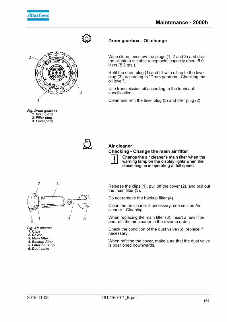
Maintenance - 2000h
4812160101_B.pdf2015-11-05
Drum gearbox - Oil change
Fig. Drum gearbox 1. Drain plug 2. Filler plug 3. Level plug
1
2
3
Wipe clean, unscrew the plugs (1, 2 and 3) and drainthe oil into a suitable receptacle, capacity about 5.0liters (5,3 qts.).
Refit the drain plug (1) and fill with oil up to the levelplug (3), according to "Drum gearbox - Checking theoil level".
Use transmission oil according to the lubricantspecification.
Clean and refit the level plug (3) and filler plug (2).
Air cleanerChecking - Change the main air filter
Change the air cleaner's main filter when thewarning lamp on the display lights when thediesel engine is operating at full speed.
Change the air cleaner's main filter when thewarning lamp on the display lights when thediesel engine is operating at full speed.
3
6 4 5
2
Fig. Air cleaner 1. Clips 2. Cover 3. Main filter 4. Backup filter 5. Filter housing 6. Dust valve
1
Release the clips (1), pull off the cover (2), and pull outthe main filter (3).
Do not remove the backup filter (4).
Clean the air cleaner if necessary, see section Aircleaner - Cleaning.
When replacing the main filter (3), insert a new filterand refit the air cleaner in the reverse order.
Check the condition of the dust valve (6); replace ifnecessary.
When refitting the cover, make sure that the dust valveis positioned downwards.
151

Maintenance - 2000h
4812160101_B.pdf 2015-11-05
Backup filter - Change
Fig. Air filter 1. Backup filter
1 Change the backup filter with a new filter after everysecond replacement of the main filter.
To change the backup filter (1), pull the old filter out ofits holder, insert a new filter and reassemble the aircleaner in the reverse order.
Clean the air cleaner if necessary, see section Aircleaner - Cleaning.
Air cleaner- Cleaning
Wipe clean on both sides of the outletpipe.
Outer edge of outletpipe.
Inner edge ofoutlet pipe.
Wipe clean the inside of the cover (2) and the filterhousing (5). See the previous illustration.
Wipe also both surfaces for the outlet pipe; seeadjacent figure.
Check that the hose clamps between the filterhousing and the suction hose are tight and thatthe hoses are intact. Inspect the entire hosesystem, all the way to the engine.
Check that the hose clamps between the filterhousing and the suction hose are tight and thatthe hoses are intact. Inspect the entire hosesystem, all the way to the engine.
152
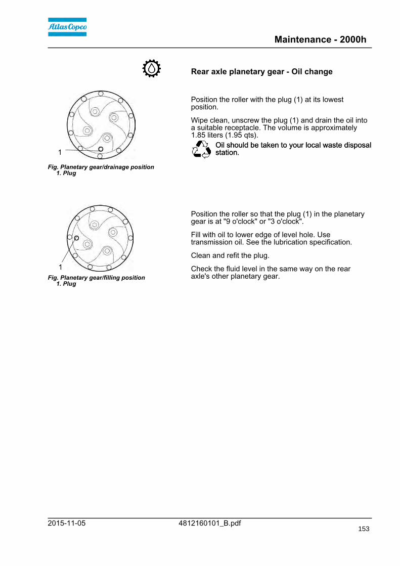
Maintenance - 2000h
4812160101_B.pdf2015-11-05
Rear axle planetary gear - Oil change
Fig. Planetary gear/drainage position 1. Plug
1
Position the roller with the plug (1) at its lowestposition.
Wipe clean, unscrew the plug (1) and drain the oil intoa suitable receptacle. The volume is approximately1.85 liters (1.95 qts).
Oil should be taken to your local waste disposalstation.Oil should be taken to your local waste disposalstation.
Fig. Planetary gear/filling position 1. Plug
1
Position the roller so that the plug (1) in the planetarygear is at "9 o'clock" or "3 o'clock".
Fill with oil to lower edge of level hole. Usetransmission oil. See the lubrication specification.
Clean and refit the plug.
Check the fluid level in the same way on the rearaxle's other planetary gear.
153
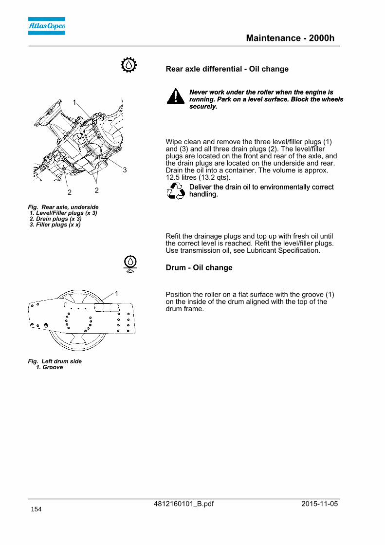
Maintenance - 2000h
4812160101_B.pdf 2015-11-05
Rear axle differential - Oil change
Fig. Rear axle, underside 1. Level/Filler plugs (x 3) 2. Drain plugs (x 3) 3. Filler plugs (x x)
3
1
22
Never work under the roller when the engine isrunning. Park on a level surface. Block the wheelssecurely.
Never work under the roller when the engine isrunning. Park on a level surface. Block the wheelssecurely.
Wipe clean and remove the three level/filler plugs (1)and (3) and all three drain plugs (2). The level/fillerplugs are located on the front and rear of the axle, andthe drain plugs are located on the underside and rear.Drain the oil into a container. The volume is approx.12.5 litres (13.2 qts).
Deliver the drain oil to environmentally correcthandling.Deliver the drain oil to environmentally correcthandling.
Refit the drainage plugs and top up with fresh oil untilthe correct level is reached. Refit the level/filler plugs.Use transmission oil, see Lubricant Specification.
Drum - Oil change
Fig. Left drum side 1. Groove
1 Position the roller on a flat surface with the groove (1)on the inside of the drum aligned with the top of thedrum frame.
154

Maintenance - 2000h
4812160101_B.pdf2015-11-05
Fig. Drum, right side 1. Filler plug 2. Level glass 3. Drain plug
1
2
3
Drum - Oil changeEnsure that the drum's plugs and level glass arepositioned as in Fig 2.
Place a vessel capable of holding at least 20 liters (5.3gal) under drain plug (3).
Remove and clean filler plug (1) and drain plug (3).
Allow all the oil to drain out. Clean and refit drain plug(3) and fill with new synthetic oil. The total volume ofoil in the drum must be 15 liters (4.0 gal).
Deliver the drain oil to environmentally correcthandling.Deliver the drain oil to environmentally correcthandling.
Make sure to only use Dynapac Drum Oil 1000 inthe drum.Make sure to only use Dynapac Drum Oil 1000 inthe drum.
Clean and refit filler plug (1).
155

Maintenance - 2000h
4812160101_B.pdf 2015-11-05
Fig. Gearbox - Drum, right side 1. Filler plug/Level plug 2. Drain plug
1
2
Gearbox - Oil changePlace the roller on a level surface.
Place a receptacle that holds at least 1 liter (0.3 gal))under the drain plug (2).
Unscrew and clean the filler/level plug (1) and thedrain plug (2).
Allow all of the oil to drain off. Clean and refit drainplug (2) and fill with oil up to filler/level plug (1). Thetotal volume of oil in the gearbox must be 0.3 liters(0.08 gal).
Deliver the drain oil to environmentally correcthandling.Deliver the drain oil to environmentally correcthandling.
Make sure to only use Dynapac Drum Oil 1000 inthe gearbox.Make sure to only use Dynapac Drum Oil 1000 inthe gearbox.
Clean and refit filler/level plug (1).
Radiator - Check/Cleaning
Fig. Engine compartment 1. Water cooler 2. Charge air cooler 3. Hydraulic fluid cooler 4. Condenser element AC (Optional) 5. Screws (x 2)
1
2
345
5 Check that air can pass unobstructed through theradiators (1), (2) and (3).
Clean a dirty radiator using compressed air or ahigh-pressure water jet.
Undo the two screws (5) and tilt the condenserelement upwards.
Blow air or direct water through the cooler in theopposite direction to that of the cooling air.
Be careful when using a high-pressure washer -do not place the nozzle too close to the radiator.Be careful when using a high-pressure washer -do not place the nozzle too close to the radiator.
Wear protective goggles when working withcompressed air or high-pressure water jets.Wear protective goggles when working withcompressed air or high-pressure water jets.
156

Maintenance - 2000h
4812160101_B.pdf2015-11-05
Fuel pre-filter - Replacement
Fig. Engine compartment 1. Fuel prefilter
1
Ensure good ventilation (air extraction) if thediesel engine is run indoors. Risk of carbonmonoxide poisoning.
Ensure good ventilation (air extraction) if thediesel engine is run indoors. Risk of carbonmonoxide poisoning.
See the engine's instruction manual for filterreplacement, in the Fuel system chapter.
Replacing the fuel filter
Fig. Engine compartment 1. Fuel filter
1
Place a container underneath to collect fuel that runsout when the filter is released.
Screw off the fuel filter (1). The filter is of thedisposable type and cannot be cleaned. Han in toenvironment-friendly station.
Deliver the drain oil to environmentally correcthandling.Deliver the drain oil to environmentally correcthandling.
Refer to the engine manual for detailedinstructions when replacing the fuel filter.Refer to the engine manual for detailedinstructions when replacing the fuel filter.
Start the engine and check that the fuel filter is tight.
Ensure good ventilation (air extraction) if thediesel engine is run indoors. Risk of carbonmonoxide poisoning.
Ensure good ventilation (air extraction) if thediesel engine is run indoors. Risk of carbonmonoxide poisoning.
NOTE! The new fuel filters must not under anycircumstances be pre-filled with fuel due to the purityrequirements of the fuel system.@@
157

Maintenance - 2000h
4812160101_B.pdf 2015-11-05
Diesel engine - Oil and Filter change
Fig. Tractor frame1. Drain plug
1
The oil drain plug (1) can be accessed most easilyfrom the right rear underside of the tractor frame, andis installed with a hose in the engine.
Drain the oil when the engine is warm. Place areceptacle that holds 19 liters (5 gal) under the drainplug.
Replace the engine oil filter (2) at the same time. Referto the engine manual.
Fig. Engine compartment 2. Oil filter
2
Take great care when draining warm fluid and oil.Wear protective gloves and goggles.Take great care when draining warm fluid and oil.Wear protective gloves and goggles.
Hand in the drained oil and filter to anenvironment-friendly waste disposal station.Hand in the drained oil and filter to anenvironment-friendly waste disposal station.
158

Maintenance - 2000h
4812160101_B.pdf2015-11-05
Seat bearing - Lubrication
2
3
1
6
4
Figure. Seat bearing 1. Grease nipple 2. Gearwheel 3. Steering chain 4. Adjusting screw 5. Cover 6. Slide rails 7. Marking
7
5 Keep in mind that the chain is a vital part of thesteering mechanism.Keep in mind that the chain is a vital part of thesteering mechanism.
Remove the cover (5) to access the lubrication nipple(1). Lubricate the operator seat slew bearing with threestrokes of a hand-operated grease gun.
Clean and grease the chain (3) between the seat andthe steering column.
Also grease the seat slide rails (6).
If the chain is slack on the sprocket (2), loosen thescrews (4) and move the steering column forward.Tighten the screws and check chain tension.
No not tension the chain too tightly. It should bepossible to move the chain about 10 mm (0.4 in) to theside with a forefinger/thumb at the marking (7) in seatframe. Fit the chain lock at the bottom.
If the seat starts to be stiff when adjusting, itshould be lubricated more often than specifiedhere.
If the seat starts to be stiff when adjusting, itshould be lubricated more often than specifiedhere.
Hydraulic reservoir - Draining
Fig. Machine's right underside 1. Drain cock 2. Plug
1
2
The condensate from the hydraulic reservoir is drainedthrough the drainage tap (1).
Drain the roller after it has been stationary for a longtime, e.g. after standing overnight. Drain as follows:
Remove the plug (2).
Place a container under the tap.
Open the tap (1) and let any trapped condensate runout.
Shut the drainage tap.
Refit the plug.
159

Maintenance - 2000h
4812160101_B.pdf 2015-11-05
Fuel tank - Draining (Optional)
Fig. Machine's right underside 1. Drain plug 2. Drain cock
1
2
Water and sediment in the fuel tank are removed viathe drainage plug in the bottom of the fuel tank.
Be very careful during draining. Do not drop theplug or else all the fuel will flow out.Be very careful during draining. Do not drop theplug or else all the fuel will flow out.
Drain the roller after it has been stationary for a longtime, e.g. after standing overnight. The fuel levelshould be as low as possible.
The roller should preferably have been standing withthis side somewhat lower, so that water and sedimentwill gather near the drainage plug (1). Drain as follows:
Place a container under the plug (1).
Loosen the drain plug (1). Then open the drain cock(2) and drain out water and sediment until only purediesel fuel emerges at the plug. Close the drain cockand screw in the plug again.
Air conditioning (Optional)Fresh air filter - Change
Fig. Cab 1. Fresh air filter (x 2) 2. Screws (x 3)
1 22 Use a step ladder to reach the filter (1). The filter
can also be accessed via the right cab window.Use a step ladder to reach the filter (1). The filtercan also be accessed via the right cab window.
There is a fresh air filter (1), located at the front of thecab.
Undo the three screws (2) and remove the protectivecover.
Remove the two air filter inserts and replace with newones.
It may be necessary to change the filters more often ifthe machine is working in a dusty environment.
160

Maintenance - 2000h
4812160101_B.pdf2015-11-05
Automatic Climate Control (Optional)- Overhaul
Fig. Engine compartment 1. Code element
1 Regular inspection and maintenance are necessary toensure satisfactory long-term operation.
Clean all dust from the condenser element (1) usingcompressed air. Blow from underneath.
The air jet can damage the element flanges if it istoo powerful.The air jet can damage the element flanges if it istoo powerful.
Wear protective goggles when working withcompressed air.Wear protective goggles when working withcompressed air.
Inspect the condenser element attachment.
Drying filter - Check
Fig. Drying filter in enginecompartment 1. Sight glass 2. Moisture indicator
1 2 With the unit in operation, open the engine hood andcheck using the sight glass (1) that bubbles are notvisible on the drying filter. If bubbles are visiblethrough the sight glass, it is a sign that the refrigerantlevel is too low. If so, stop the unit. The unit may bedamaged if it is run with insufficient refrigerant.
Check the moisture indicator (2). It should be blue. If itis beige, the dryer cartridge should be changed by anauthorized service company.
The compressor will be damaged if the unit is runwith too little refrigerant.The compressor will be damaged if the unit is runwith too little refrigerant.
Do not disconnect or undo the hose couplings.Do not disconnect or undo the hose couplings.
The cooling system is pressurized. Incorrecthandling can result in serious personal injury.The cooling system is pressurized. Incorrecthandling can result in serious personal injury.
The system contains pressurized refrigerant. It isforbidden to release refrigerants into theatmosphere. Work on the refrigerant circuit is onlyto be carriedd out by authorized companies.
The system contains pressurized refrigerant. It isforbidden to release refrigerants into theatmosphere. Work on the refrigerant circuit is onlyto be carriedd out by authorized companies.
161

Maintenance - 2000h
4812160101_B.pdf 2015-11-05
Steering hitch - Tightening
Fig. Steering hitch 1. Nut
1
Nobody must be allowed near the steering jointwhen the engine is running. Risk of beingcrushed when the steering is operated. Switchoff the engine and activate the parking brakebefore lubricating.
Nobody must be allowed near the steering jointwhen the engine is running. Risk of beingcrushed when the steering is operated. Switchoff the engine and activate the parking brakebefore lubricating.
The easiest way to identify if you have this type ofsteering hitch is that it has a new type of nut (1) at thetop, as shown.
Actual torque (Nm) should be when the machine'sposition is straight ahead.M14 174 NmM14 174 NmM16 270 NmM16 270 Nm
162


Atlas Copco Road Construction Equipment
Dynapac Compaction Equipment AB
Box 504, SE 371 23 Karlskrona, Sweden
www.dynapac.com