Embed Size (px)
Citation preview

www.rkiinstruments.com
Instruction ManualEagle Series
Portable Multi-Gas Detector
Part Number: 71-0028RK
Revision: H
Released: 3/15/13
Eagle Instruction Manual
WARNING
Read and understand this instruction manual before operating instrument. Improper use of the gas monitor could result in bodily harm or death.
Periodic calibration and maintenance of the gas monitor is essential for proper operation and correct readings. Please calibrate and maintain this instrument regularly! Frequency of calibration depends upon the type of use you have and the sensor types. Typical calibration frequencies for most applications are between 1 and 3 months, but can be required more often or less often based on your usage.
Eagle Instruction Manual
Warranty
RKI Instruments, Inc. warranties gas alarm equipment manufactured by RKI and sold by RKI to be free from defects in materials and workmanship for a period of one year from date of shipment from RKI Instruments, Inc. Any parts found defective within that period will be repaired or replaced, at our option, free of charge. This warranty does not apply to items that are subject to deterioration or consumption in normal service, and which must be cleaned, repaired, or replaced routinely. Those items include, but are not limited to:
This warranty is voided by mechanical damage, misuse, alteration, rough handling, or repairs not in accordance with the operator’s manual. This warranty indicates the full extent of our liability. We are not responsible for removal or replacement costs, local repair costs, transportation costs, or contingent expenses incurred without our prior approval.
THIS WARRANTY IS IN LIEU OF ANY OTHER WARRANTIES AND REPRESENTATIONS, EXPRESSED OR IMPLIED, AND ALL OTHER OBLIGATIONS OR LIABILITIES ON THE PART OF RKI INSTRUMENTS, INC. INCLUDING BUT NOT LIMITED TO THE WARRANTY OF MERCHANTABILITY OR FITNESS FOR A PARTICULAR PURPOSE. IN NO EVENT SHALL RKI INSTRUMENTS, INC. BE LIABLE FOR INDIRECT, INCIDENTAL, OR CONSEQUENTIAL LOSS OR DAMAGE OF ANY KIND CONNECTED WITH THE USE OF ITS PRODUCTS OR FAILURE OF ITS PRODUCTS TO FUNCTION OR OPERATE PROPERLY.
This warranty covers instruments and parts sold to end users by authorized distributors, dealers, and representatives of RKI Instruments, Inc.
We do not assume indemnification for any accident or damage caused by the operation of this gas monitor. Our warranty is limited to replacement of parts or our complete goods.
absorbent cartridges filter elements
pump diaphragms and valves batteries
lamp bulbs and fuses
Eagle Instruction Manual
Table of Contents
Introduction . . . . . . . . . . . . . . . . . . . . . . . . . . . . . . . . . . . . . . . . . . . . . 1Overview . . . . . . . . . . . . . . . . . . . . . . . . . . . . . . . . . . . . . . . . . . . . . . . . . . . 1About this Manual . . . . . . . . . . . . . . . . . . . . . . . . . . . . . . . . . . . . . . . . . . . 2
Specifications. . . . . . . . . . . . . . . . . . . . . . . . . . . . . . . . . . . . . . . . . . . . 3
Description . . . . . . . . . . . . . . . . . . . . . . . . . . . . . . . . . . . . . . . . . . . . . . 5
Case . . . . . . . . . . . . . . . . . . . . . . . . . . . . . . . . . . . . . . . . . . . . . . . . . . . . . . . . 5Control Panel . . . . . . . . . . . . . . . . . . . . . . . . . . . . . . . . . . . . . . . . . . . . . . . . 5Buttons . . . . . . . . . . . . . . . . . . . . . . . . . . . . . . . . . . . . . . . . . . . . . . . . . . . . . 5Alarm Lights . . . . . . . . . . . . . . . . . . . . . . . . . . . . . . . . . . . . . . . . . . . . . . . . 6Battery Charger Connector . . . . . . . . . . . . . . . . . . . . . . . . . . . . . . . . . . . . 6Interface Port . . . . . . . . . . . . . . . . . . . . . . . . . . . . . . . . . . . . . . . . . . . . . . . . 6Buzzer . . . . . . . . . . . . . . . . . . . . . . . . . . . . . . . . . . . . . . . . . . . . . . . . . . . . . . 6Sample-Drawing System . . . . . . . . . . . . . . . . . . . . . . . . . . . . . . . . . . . . . . 6Hose and Probe . . . . . . . . . . . . . . . . . . . . . . . . . . . . . . . . . . . . . . . . . . . . . . 6Sensors . . . . . . . . . . . . . . . . . . . . . . . . . . . . . . . . . . . . . . . . . . . . . . . . . . . . . 8Circuit Boards . . . . . . . . . . . . . . . . . . . . . . . . . . . . . . . . . . . . . . . . . . . . . . . 9Methane Elimination Switch . . . . . . . . . . . . . . . . . . . . . . . . . . . . . . . . . . . 9CAL/SETUP Switch . . . . . . . . . . . . . . . . . . . . . . . . . . . . . . . . . . . . . . . . . . 9
Operation . . . . . . . . . . . . . . . . . . . . . . . . . . . . . . . . . . . . . . . . . . . . . . 10Starting Up the Eagle . . . . . . . . . . . . . . . . . . . . . . . . . . . . . . . . . . . . . . . . 10Normal Operation. . . . . . . . . . . . . . . . . . . . . . . . . . . . . . . . . . . . . . . . . . . 12Monitoring Combustible Gas in the PPM Range . . . . . . . . . . . . . . . . . 12Monitoring Combustible Gases Other Than Methane . . . . . . . . . . . . 12Setting User Access . . . . . . . . . . . . . . . . . . . . . . . . . . . . . . . . . . . . . . . . . . 14Turning Off the Eagle . . . . . . . . . . . . . . . . . . . . . . . . . . . . . . . . . . . . . . . . 14
Alarms . . . . . . . . . . . . . . . . . . . . . . . . . . . . . . . . . . . . . . . . . . . . . . . . . 15
Alarm Indications . . . . . . . . . . . . . . . . . . . . . . . . . . . . . . . . . . . . . . . . . . . 15Resetting Gas Alarms . . . . . . . . . . . . . . . . . . . . . . . . . . . . . . . . . . . . . . . . 19
Eagle Instruction Manual
Display Mode . . . . . . . . . . . . . . . . . . . . . . . . . . . . . . . . . . . . . . . . . . 20User and Station ID Screen . . . . . . . . . . . . . . . . . . . . . . . . . . . . . . . . . . . 20Peak Screen. . . . . . . . . . . . . . . . . . . . . . . . . . . . . . . . . . . . . . . . . . . . . . . . . 21Elapsed Time Screen . . . . . . . . . . . . . . . . . . . . . . . . . . . . . . . . . . . . . . . . . 21TWA/STEL Screen . . . . . . . . . . . . . . . . . . . . . . . . . . . . . . . . . . . . . . . . . . 22Battery Voltage Screen . . . . . . . . . . . . . . . . . . . . . . . . . . . . . . . . . . . . . . . 22Date/Time Screen . . . . . . . . . . . . . . . . . . . . . . . . . . . . . . . . . . . . . . . . . . . 22Clear Data Logger Screens . . . . . . . . . . . . . . . . . . . . . . . . . . . . . . . . . . . . 23Remaining Log Time Screen . . . . . . . . . . . . . . . . . . . . . . . . . . . . . . . . . . 23
Setup Mode . . . . . . . . . . . . . . . . . . . . . . . . . . . . . . . . . . . . . . . . . . . . 24Tips for Using Setup Mode . . . . . . . . . . . . . . . . . . . . . . . . . . . . . . . . . . . 24Entering Setup Mode . . . . . . . . . . . . . . . . . . . . . . . . . . . . . . . . . . . . . . . . 25Updating the Battery Type Setting . . . . . . . . . . . . . . . . . . . . . . . . . . . . . 25Updating Channel Settings . . . . . . . . . . . . . . . . . . . . . . . . . . . . . . . . . . . 26Updating the Combustible Gas Channel’s Units of Measure. . . . . . . 32Updating the Alarm Point Settings . . . . . . . . . . . . . . . . . . . . . . . . . . . . 33Updating the Eagle’s Serial Number . . . . . . . . . . . . . . . . . . . . . . . . . . . 34Updating the Lunch Break Setting . . . . . . . . . . . . . . . . . . . . . . . . . . . . . 34Updating the Alarm Latching Setting . . . . . . . . . . . . . . . . . . . . . . . . . . 35Updating the Alarm Silence Setting . . . . . . . . . . . . . . . . . . . . . . . . . . . . 35Turning the User ID Function On or Off . . . . . . . . . . . . . . . . . . . . . . . . 36Updating the Auto Calibration Settings . . . . . . . . . . . . . . . . . . . . . . . . 36Updating the Back Light Setting. . . . . . . . . . . . . . . . . . . . . . . . . . . . . . . 37Turning the Auto Fresh Air Function On or Off. . . . . . . . . . . . . . . . . . 37Updating the Interval Time Setting (data log option) . . . . . . . . . . . . . 38Updating the Log Data Over Write Setting (data log option) . . . . . . 38Updating the Time Calibration Setting (data log option) . . . . . . . . . . 39Updating the Date and Time Settings (data log option) . . . . . . . . . . . 39Updating the Zero Follow Settings. . . . . . . . . . . . . . . . . . . . . . . . . . . . . 40Updating the Confirmation Beep Setting . . . . . . . . . . . . . . . . . . . . . . . 40Returning to Default Settings . . . . . . . . . . . . . . . . . . . . . . . . . . . . . . . . . 40
Eagle Instruction Manual
Calibration . . . . . . . . . . . . . . . . . . . . . . . . . . . . . . . . . . . . . . . . . . . . . 42Calibration Supplies and Equipment. . . . . . . . . . . . . . . . . . . . . . . . . . . 42Preparing for Calibration . . . . . . . . . . . . . . . . . . . . . . . . . . . . . . . . . . . . . 42Calibrating the Eagle . . . . . . . . . . . . . . . . . . . . . . . . . . . . . . . . . . . . . . . . 43
Maintenance. . . . . . . . . . . . . . . . . . . . . . . . . . . . . . . . . . . . . . . . . . . . 47Displaying the Battery Voltage . . . . . . . . . . . . . . . . . . . . . . . . . . . . . . . . 47Replacing Alkaline Batteries . . . . . . . . . . . . . . . . . . . . . . . . . . . . . . . . . . 47Recharging Ni-Cd Batteries . . . . . . . . . . . . . . . . . . . . . . . . . . . . . . . . . . . 47Replacing the Probe’s Particle Filter and Hydrophobic Filter Disk. . 48Replacing Sensors . . . . . . . . . . . . . . . . . . . . . . . . . . . . . . . . . . . . . . . . . . . 49
Appendix A: Parts List . . . . . . . . . . . . . . . . . . . . . . . . . . . . . . . . . . . 53
Appendix B: Methane Elimination . . . . . . . . . . . . . . . . . . . . . . . . 55Setting up for Methane Elimination Mode . . . . . . . . . . . . . . . . . . . . . . 55Operating With Methane Response OFF . . . . . . . . . . . . . . . . . . . . . . . . 55Returning to Methane Response Mode . . . . . . . . . . . . . . . . . . . . . . . . . 55Monitoring Combustible Gases Other Than Hexane . . . . . . . . . . . . . 56
Appendix C: Non-Standard Toxic Gas Sensors. . . . . . . . . . . . . . 57Specifications . . . . . . . . . . . . . . . . . . . . . . . . . . . . . . . . . . . . . . . . . . . . . . . 57Description . . . . . . . . . . . . . . . . . . . . . . . . . . . . . . . . . . . . . . . . . . . . . . . . . 58Keeping Fresh Batteries in a Non-Standard Toxic Eagle . . . . . . . . . . . 59Calibrating Non-Standard Toxic Gas Sensors. . . . . . . . . . . . . . . . . . . . 59Replacing Non-Standard Toxic Gas Sensors . . . . . . . . . . . . . . . . . . . . . 61Parts List . . . . . . . . . . . . . . . . . . . . . . . . . . . . . . . . . . . . . . . . . . . . . . . . . . . 62
Appendix D: Carbon Dioxide Sensors . . . . . . . . . . . . . . . . . . . . . 64Specifications . . . . . . . . . . . . . . . . . . . . . . . . . . . . . . . . . . . . . . . . . . . . . . . 64Description . . . . . . . . . . . . . . . . . . . . . . . . . . . . . . . . . . . . . . . . . . . . . . . . . 64Normal Operation of Carbon Dioxide Sensors. . . . . . . . . . . . . . . . . . . 65Demand Zero for Carbon Dioxide Sensors . . . . . . . . . . . . . . . . . . . . . . 65Calibrating Carbon Dioxide Sensors . . . . . . . . . . . . . . . . . . . . . . . . . . . 66Replacing Carbon Dioxide Sensors . . . . . . . . . . . . . . . . . . . . . . . . . . . . 68Parts List . . . . . . . . . . . . . . . . . . . . . . . . . . . . . . . . . . . . . . . . . . . . . . . . . . . 68
Eagle Instruction Manual
Appendix E: Infrared Methane Sensors . . . . . . . . . . . . . . . . . . . . 69Target Gases . . . . . . . . . . . . . . . . . . . . . . . . . . . . . . . . . . . . . . . . . . . . . . . . 69Specifications . . . . . . . . . . . . . . . . . . . . . . . . . . . . . . . . . . . . . . . . . . . . . . . 69Description . . . . . . . . . . . . . . . . . . . . . . . . . . . . . . . . . . . . . . . . . . . . . . . . . 69Calibrating Infrared Methane Sensors . . . . . . . . . . . . . . . . . . . . . . . . . . 70Replacing Infrared Methane Sensors . . . . . . . . . . . . . . . . . . . . . . . . . . . 71Parts List . . . . . . . . . . . . . . . . . . . . . . . . . . . . . . . . . . . . . . . . . . . . . . . . . . . 71
Appendix F: Eagle Tank Tester Model . . . . . . . . . . . . . . . . . . . . . 72Description . . . . . . . . . . . . . . . . . . . . . . . . . . . . . . . . . . . . . . . . . . . . . . . . . 72Alarms. . . . . . . . . . . . . . . . . . . . . . . . . . . . . . . . . . . . . . . . . . . . . . . . . . . . . 73Calibration . . . . . . . . . . . . . . . . . . . . . . . . . . . . . . . . . . . . . . . . . . . . . . . . . 73Parts List . . . . . . . . . . . . . . . . . . . . . . . . . . . . . . . . . . . . . . . . . . . . . . . . . . . 74
Appendix G: Five-Gas and Six-Gas Models . . . . . . . . . . . . . . . . 75Overview . . . . . . . . . . . . . . . . . . . . . . . . . . . . . . . . . . . . . . . . . . . . . . . . . . 75Displaying Additional Channels . . . . . . . . . . . . . . . . . . . . . . . . . . . . . . 75Alarms. . . . . . . . . . . . . . . . . . . . . . . . . . . . . . . . . . . . . . . . . . . . . . . . . . . . . 76Calibration, Display, and Setup Modes . . . . . . . . . . . . . . . . . . . . . . . . . 76
Appendix H: Eagle Transformer Gas Tester . . . . . . . . . . . . . . . . 77Description . . . . . . . . . . . . . . . . . . . . . . . . . . . . . . . . . . . . . . . . . . . . . . . . . 77Operation . . . . . . . . . . . . . . . . . . . . . . . . . . . . . . . . . . . . . . . . . . . . . . . . . . 77Alarms. . . . . . . . . . . . . . . . . . . . . . . . . . . . . . . . . . . . . . . . . . . . . . . . . . . . . 78Parts List . . . . . . . . . . . . . . . . . . . . . . . . . . . . . . . . . . . . . . . . . . . . . . . . . . . 75
Appendix I: Installing the Data Logger Board . . . . . . . . . . . . . . 79
Appendix J: Infrared HC Sensor . . . . . . . . . . . . . . . . . . . . . . . . . . 80Target Gases . . . . . . . . . . . . . . . . . . . . . . . . . . . . . . . . . . . . . . . . . . . . . . . . 80Specifications . . . . . . . . . . . . . . . . . . . . . . . . . . . . . . . . . . . . . . . . . . . . . . . 80Description . . . . . . . . . . . . . . . . . . . . . . . . . . . . . . . . . . . . . . . . . . . . . . . . . 80Calibrating the Infrared HC Sensor . . . . . . . . . . . . . . . . . . . . . . . . . . . . 81Replacing the Infrared HC Sensor . . . . . . . . . . . . . . . . . . . . . . . . . . . . . 82Parts List . . . . . . . . . . . . . . . . . . . . . . . . . . . . . . . . . . . . . . . . . . . . . . . . . . . 82
1 • Introduction Eagle Instruction Manual
Introduction
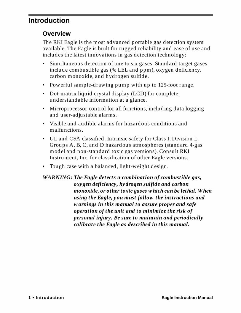
OverviewThe RKI Eagle is the most advanced portable gas detection system available. The Eagle is built for rugged reliability and ease of use and includes the latest innovations in gas detection technology:
• Simultaneous detection of one to six gases. Standard target gases include combustible gas (% LEL and ppm), oxygen deficiency, carbon monoxide, and hydrogen sulfide.
• Powerful sample-drawing pump with up to 125-foot range.
• Dot-matrix liquid crystal display (LCD) for complete, understandable information at a glance.
• Microprocessor control for all functions, including data logging and user-adjustable alarms.
• Visible and audible alarms for hazardous conditions and malfunctions.
• UL and CSA classified. Intrinsic safety for Class I, Division I, Groups A, B, C, and D hazardous atmospheres (standard 4-gas model and non-standard toxic gas versions). Consult RKI Instrument, Inc. for classification of other Eagle versions.
• Tough case with a balanced, light-weight design.
WARNING: The Eagle detects a combination of combustible gas, oxygen deficiency, hydrogen sulfide and carbon monoxide, or other toxic gases which can be lethal. When using the Eagle, you must follow the instructions and warnings in this manual to assure proper and safe operation of the unit and to minimize the risk of personal injury. Be sure to maintain and periodically calibrate the Eagle as described in this manual.
Eagle Instruction Manual Introduction • 2
About this ManualThis manual is intended for use with all Eagle models. Examples used in this manual are for the standard four-gas model (combustible gas, oxygen, carbon monoxide, and hydrogen sulfide). Differences between the standard four-gas model and other Eagle models are noted where applicable. This manual is organized as follows:
• The standard sections included in pages 1 through 52 describe the Eagle’s specifications and internal and external components. These sections also describe the operation, calibration, and maintenance of the Eagle.
• Appendix A lists part numbers for the Eagle’s replacement parts and accessories.
• Appendix B describes the Eagle’s methane elimination feature.
• Appendix C describes the non-standard toxic sensors.
• Appendix D describes the infrared carbon dioxide special sensor.
• Appendix E describes the infrared CH4 special sensor.
• Appendix F describes the Eagle tank tester model.
• Appendix G describes the Eagle’s five- and six-gas models.
• Appendix H describes the Eagle transformer gas tester model.
• Appendix I describes the procedure to install the Eagle’s optional Data Logger board.
• Appendix J describes the infrared HC special sensor.
3 • Specifications Eagle Instruction Manual
Specifications
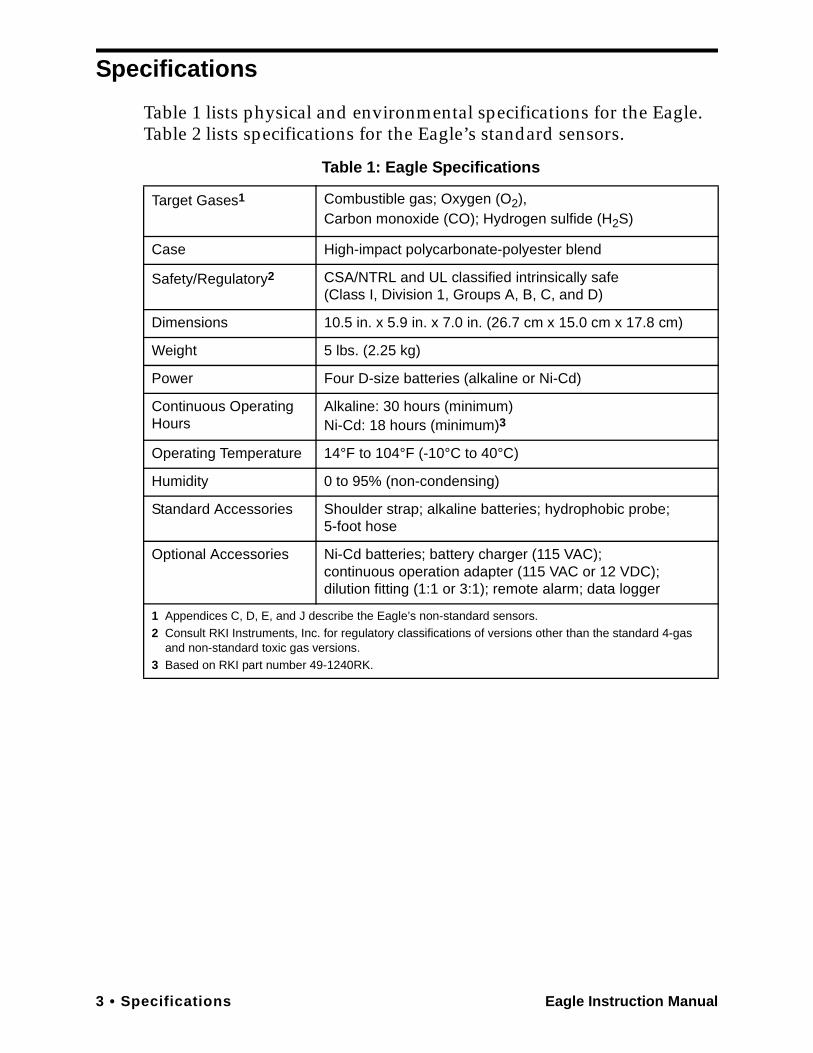
Table 1 lists physical and environmental specifications for the Eagle. Table 2 lists specifications for the Eagle’s standard sensors.
Table 1: Eagle Specifications
Target Gases1 Combustible gas; Oxygen (O2),Carbon monoxide (CO); Hydrogen sulfide (H2S)
Case High-impact polycarbonate-polyester blend
Safety/Regulatory2 CSA/NTRL and UL classified intrinsically safe(Class I, Division 1, Groups A, B, C, and D)
Dimensions 10.5 in. x 5.9 in. x 7.0 in. (26.7 cm x 15.0 cm x 17.8 cm)
Weight 5 lbs. (2.25 kg)
Power Four D-size batteries (alkaline or Ni-Cd)
Continuous Operating Hours
Alkaline: 30 hours (minimum)Ni-Cd: 18 hours (minimum)3
Operating Temperature 14°F to 104°F (-10°C to 40°C)
Humidity 0 to 95% (non-condensing)
Standard Accessories Shoulder strap; alkaline batteries; hydrophobic probe;5-foot hose
Optional Accessories Ni-Cd batteries; battery charger (115 VAC);continuous operation adapter (115 VAC or 12 VDC);dilution fitting (1:1 or 3:1); remote alarm; data logger
1 Appendices C, D, E, and J describe the Eagle’s non-standard sensors.2 Consult RKI Instruments, Inc. for regulatory classifications of versions other than the standard 4-gas
and non-standard toxic gas versions.3 Based on RKI part number 49-1240RK.

Eagle Instruction Manual Specifications • 4
Table 2 lists specifications for the Eagle’s standard sensors. Your Eagle model may not include all of the sensors listed below. The alarm settings are user-adjustable (see “Updating the Alarm Point Settings” on page 33).
Table 2: Standard Sensor Specifications
Combustible Gas (%LEL1)
Combustible Gas (PPM2)
Oxygen Hydrogen Sulfide
Carbon Monoxide
Range 0 to 100% LEL Depends on target gas4
0 to 40% O2 0 to 100 ppm
0 to 500 ppm
Alarm 1 10% LEL 5000 ppm 19.5% O2 (decreasing)
10.0 ppm 25 ppm
Alarm 2 50% LEL 25,000 ppm 23.5% O2 (increasing)
30.0 ppm 50 ppm
TWA Alarm N/A N/A N/A 10.0 ppm 25 ppm
STEL Alarm N/A N/A N/A 15.0 ppm 400 ppm
Detection Principle
Catalytic combustion
Catalytic combustion
Electro-chemical
Electro-chemical
Electro-chemical
Response Time(to 90%)5
30 seconds 30 seconds 30 seconds 30 seconds 30 seconds
Accuracy(of fullscale)
± 5% of reading or ± 2% LEL
(whichever is greater)
± 25 ppm or ± 5% of reading
(whichever is greater)
under ideal conditions
± 0.5% O2 ± 5% of reading or ± 2 ppm
H2S (whichever is greater)
± 5% of reading or
± 5 ppm CO (whichever is greater)
1 LEL (Lower Explosive Limit)2 PPM (Parts Per Million)3 Alarms settings are user adjustable. See “Updating the Alarm Point Settings” on page 33.
4 The PPM range represents the same range as 0 to 100% LEL for that gas. For example, 100% LEL for methane = 5% by volume = 50,000 PPM. Therefore, the PPM range for methane is 0 to 50,000.
5 With the Eagle’s standard hose and probe attached.
5 • Description Eagle Instruction Manual
Description
CaseThe Eagle has a plastic case with a full-sized handle. The high-visibility case is shielded to reduce radio frequency and electromagnetic interference (RFI/EMI). The system is light-weight and balanced, which makes the Eagle easy to carry and use for extended periods. A foam rubber gasket between the top and bottom case components is water- and dust-resistant. You can set the case into 2.5 in. of water without damage.
Control PanelThe control panel is at the top of the Eagle. The touch-pad buttons reduce the risk of accidental activation. The dot matrix display simultaneously shows the gas reading for all installed sensors. (For the 5- and 6-gas versions, the Eagle displays the gas reading of four channels. Use the AIR/▲ and SHIFT/▼ buttons to scroll to the non-displayed channels.) The display also shows information for each of the Eagle’s program modes.
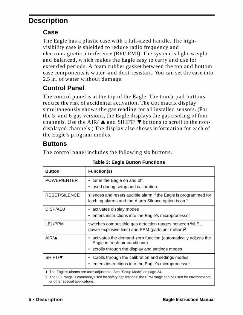
ButtonsThe control panel includes the following six buttons.
Table 3: Eagle Button Functions
Button Function(s)
POWER/ENTER • turns the Eagle on and off.
• used during setup and calibration.
RESET/SILENCE silences and resets audible alarm if the Eagle is programmed for latching alarms and the Alarm Silence option is on 1
DISP/ADJ • activates display modes
• enters instructions into the Eagle’s microprocessor
LEL/PPM switches combustible gas detection ranges between %LEL (lower explosive limit) and PPM (parts per million)2
AIR/▲ • activates the demand-zero function (automatically adjusts the Eagle in fresh-air conditions)
• scrolls through the display and settings modes
SHIFT/▼ • scrolls through the calibration and settings modes
• enters instructions into the Eagle’s microprocessor
1 The Eagle’s alarms are user-adjustable. See “Setup Mode” on page 24.
2 The LEL range is commonly used for safety applications; the PPM range can be used for environmental or other special applications.
Eagle Instruction Manual Description • 6
Alarm LightsTwo ultra-bright, red, light-emitting diodes (LEDs) provide visual alarms for gas concentrations and malfunctions. They are mounted on the top rear of the case for greatest visibility.
Battery Charger ConnectorThe battery charger connector is mounted on the top right rear of the case. The external battery charger connects to this connector to recharge nickel-cadmium (Ni-Cd) batteries. The continuous operation adapter also connects to the battery charger connector.
Interface PortThe interface port is for the optional data logging or remote buzzer. The port is mounted on the top left rear of the case. When the Data Logging option is installed, the Eagle records gas concentrations at programmed intervals and stores data on gas detected. You can download these measurements through the interface port to a PC-compatible computer for use in data analysis programs. Data retrieval requires the Eagle Data Downloader Kit (with PC connection cable and software).
The optional remote buzzer also connects to the interface port. The remote buzzer is for use in applications where a remote alarm indication is required.
BuzzerA solid-state electronic buzzer is mounted inside the top of the case. The buzzer sounds for gas alarms, malfunction, low battery voltage, and as an indicator during use of the Eagle’s many display and adjustment options.
Sample-Drawing SystemThe sample-drawing system includes the pump, sensor block and connections, internal filter and charcoal scrubber, and the external hose, probe, and hydrophobic filter. This system provides continuous flow of sampled air to the sensors while keeping out liquids and dust.
With proper setup, the system can draw a sample flow from up to 125 feet away from the Eagle. Consult RKI Instruments, Inc. for sample flow distances longer than 125 feet.
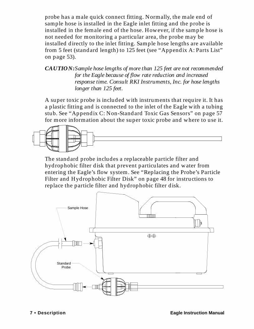
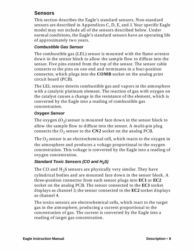
Hose and ProbeA 5 foot polyurethane sample hose and a 10 inch hydrophobic probe are included as standard. The hose has a male quick connect fitting on one end and a female quick connect fitting on the other end. The
7 • Description Eagle Instruction Manual
probe has a male quick connect fitting. Normally, the male end of sample hose is installed in the Eagle inlet fitting and the probe is installed in the female end of the hose. However, if the sample hose is not needed for monitoring a particular area, the probe may be installed directly to the inlet fitting. Sample hose lengths are available from 5 feet (standard length) to 125 feet (see “Appendix A: Parts List” on page 53).
CAUTION:Sample hose lengths of more than 125 feet are not recommended for the Eagle because of flow rate reduction and increased response time. Consult RKI Instruments, Inc. for hose lengths longer than 125 feet.
A super toxic probe is included with instruments that require it. It has a plastic fitting and is connected to the inlet of the Eagle with a tubing stub. See “Appendix C: Non-Standard Toxic Gas Sensors” on page 57 for more information about the super toxic probe and where to use it.
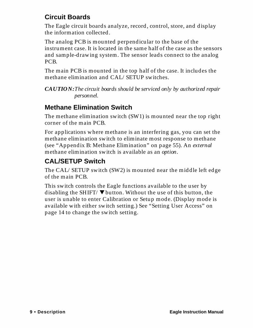
The standard probe includes a replaceable particle filter and hydrophobic filter disk that prevent particulates and water from entering the Eagle’s flow system. See “Replacing the Probe’s Particle Filter and Hydrophobic Filter Disk” on page 48 for instructions to replace the particle filter and hydrophobic filter disk.
Standard Probe
Sample Hose
Eagle Instruction Manual Description • 8
SensorsThis section describes the Eagle’s standard sensors. Non-standard sensors are described in Appendices C, D, E, and J. Your specific Eagle model may not include all of the sensors described below. Under normal conditions, the Eagle’s standard sensors have an operating life of approximately two years.
Combustible Gas Sensor
The combustible gas (LEL) sensor is mounted with the flame arrestor down in the sensor block to allow the sample flow to diffuse into the sensor. Five pins extend from the top of the sensor. The sensor cable connects to the pins on one end and terminates in a four-position connector, which plugs into the COMB socket on the analog print circuit board (PCB).
The LEL sensor detects combustible gas and vapors in the atmosphere with a catalytic platinum element. The reaction of gas with oxygen on the catalyst causes a change in the resistance of the element, which is converted by the Eagle into a reading of combustible gas concentration.
Oxygen Sensor
The oxygen (O2) sensor is mounted face down in the sensor block to allow the sample flow to diffuse into the sensor. A multi-pin plug connects the O2 sensor to the CN2 socket on the analog PCB.
The O2 sensor is an electrochemical cell, which reacts to the oxygen in the atmosphere and produces a voltage proportional to the oxygen concentration. This voltage is converted by the Eagle into a reading of oxygen concentration.
Standard Toxic Sensors (CO and H2S)
The CO and H2S sensors are physically very similar. They have cylindrical bodies and are mounted face down in the sensor block. A three-position connector from each sensor plugs into EC1 or EC2 socket on the analog PCB. The sensor connected to the EC1 socket displays as channel 3; the sensor connected to the EC2 socket displays as channel 4.
The toxics sensors are electrochemical cells, which react to the target gas in the atmosphere, producing a current proportional to the concentration of gas. The current is converted by the Eagle into a reading of target gas concentration.
9 • Description Eagle Instruction Manual
Circuit BoardsThe Eagle circuit boards analyze, record, control, store, and display the information collected.
The analog PCB is mounted perpendicular to the base of the instrument case. It is located in the same half of the case as the sensors and sample-drawing system. The sensor leads connect to the analog PCB.
The main PCB is mounted in the top half of the case. It includes the methane elimination and CAL/SETUP switches.
CAUTION:The circuit boards should be serviced only by authorized repair personnel.
Methane Elimination SwitchThe methane elimination switch (SW1) is mounted near the top right corner of the main PCB.
For applications where methane is an interfering gas, you can set the methane elimination switch to eliminate most response to methane(see “Appendix B: Methane Elimination” on page 55). An external methane elimination switch is available as an option.
CAL/SETUP SwitchThe CAL/SETUP switch (SW2) is mounted near the middle left edge of the main PCB.
This switch controls the Eagle functions available to the user by disabling the SHIFT/▼ button. Without the use of this button, the user is unable to enter Calibration or Setup mode. (Display mode is available with either switch setting.) See “Setting User Access” on page 14 to change the switch setting.
Eagle Instruction Manual Operation • 10
Operation
The Eagle has four operating modes: normal operating mode, display mode, setup mode, and calibration mode. This section describes the Eagle in normal operating mode. It includes procedures to start up the Eagle, set various detection options for the combustible gas channel, and shut down the Eagle.
NOTE: The screens illustrated in this section are intended as examples only. The screens displayed by your Eagle model may be slightly different.
Starting Up the Eagle1. Connect the sample hose to the Eagle’s quick connect inlet fitting.
2. Connect the hydrophobic filter and probe tip to the sample hose’s quick connect fitting.
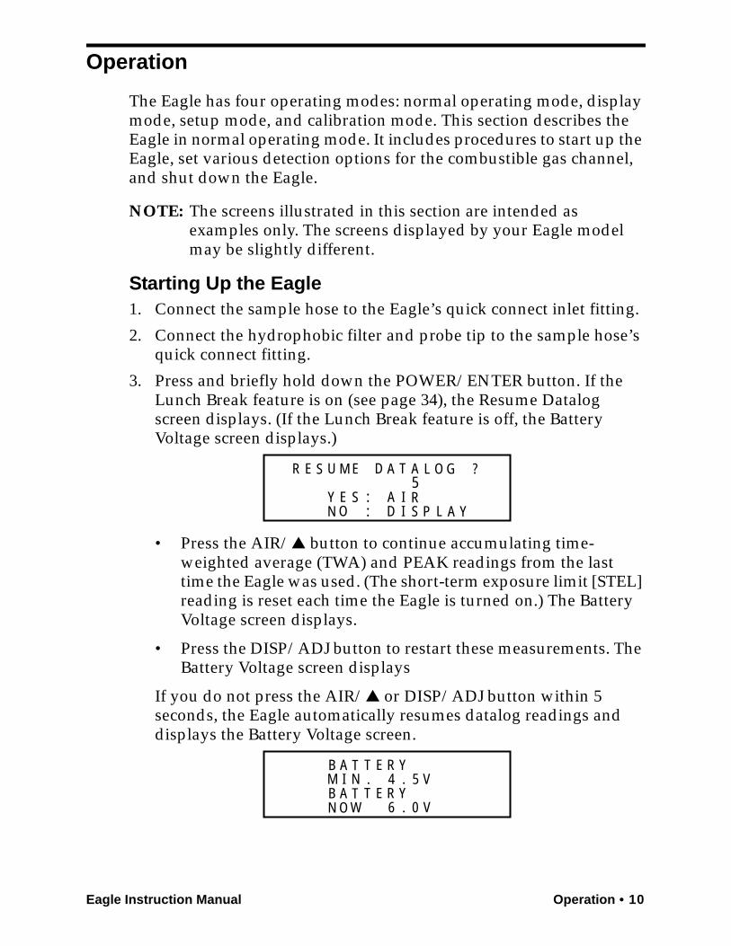
3. Press and briefly hold down the POWER/ENTER button. If the Lunch Break feature is on (see page 34), the Resume Datalog screen displays. (If the Lunch Break feature is off, the Battery Voltage screen displays.)
• Press the AIR/▲ button to continue accumulating time-weighted average (TWA) and PEAK readings from the last time the Eagle was used. (The short-term exposure limit [STEL] reading is reset each time the Eagle is turned on.) The Battery Voltage screen displays.
• Press the DISP/ADJ button to restart these measurements. The Battery Voltage screen displays
If you do not press the AIR/▲ or DISP/ADJ button within 5 seconds, the Eagle automatically resumes datalog readings and displays the Battery Voltage screen.
E S U D T
N IY E S
A A
A:
L
RS
ID
O GR M E ?
O P:
5
L A Y
B A T T E R YM I N . 4 . 5 VB A T T E R Y
6 0 V.N O W
11 • Operation Eagle Instruction Manual
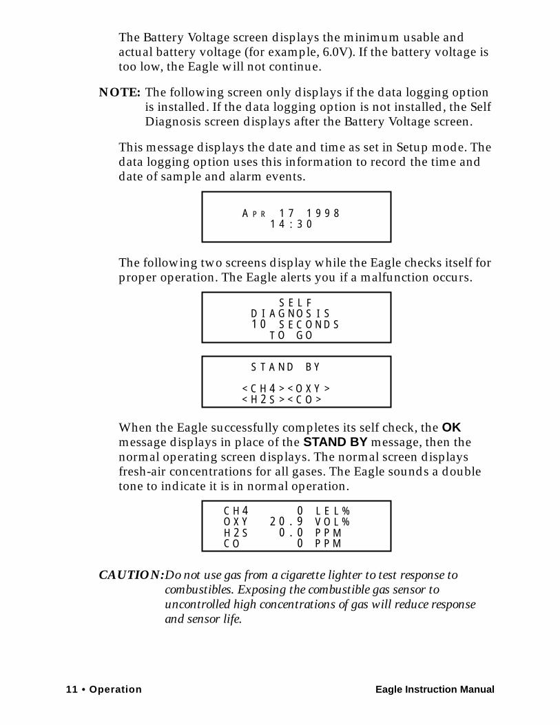
The Battery Voltage screen displays the minimum usable and actual battery voltage (for example, 6.0V). If the battery voltage is too low, the Eagle will not continue.
NOTE: The following screen only displays if the data logging option is installed. If the data logging option is not installed, the Self Diagnosis screen displays after the Battery Voltage screen.
This message displays the date and time as set in Setup mode. The data logging option uses this information to record the time and date of sample and alarm events.
The following two screens display while the Eagle checks itself for proper operation. The Eagle alerts you if a malfunction occurs.
When the Eagle successfully completes its self check, the OK message displays in place of the STAND BY message, then the normal operating screen displays. The normal screen displays fresh-air concentrations for all gases. The Eagle sounds a double tone to indicate it is in normal operation.
CAUTION:Do not use gas from a cigarette lighter to test response to combustibles. Exposing the combustible gas sensor to uncontrolled high concentrations of gas will reduce response and sensor life.
PA 1 7 14 :
R 9 9 81 3 0
SG N SS E
I SC O
D I A OE L F
0 N D ST O G O
S T A N D B Y
C H 4 > < O YC >OH 2 S
< X> <<
>
1
C H 4O Y
C OH 2 S
X 2 0 . 90
00.0
LVPP
PP
MM
EO
LL
%%
Eagle Instruction Manual Operation • 12
4. Verify that the Eagle is operating correctly. Use the RKI Check Kit to easily verify correct operation of the Eagle.
WARNING: If the Eagle does not respond to verification, take it to a known “fresh-air” environment, then perform the demand zero procedure described in “Preparing for Calibration” on page 42. Repeat step 4 before using the Eagle in a potentially hazardous location.
Normal OperationThe Eagle continuously monitors the sampled atmosphere and displays the gas concentrations present for its target gases. In a low-light environment, press any button to turn on the display backlight. (See “Updating the Back Light Setting” on page 37 to program backlight duration.) If the Confirmation Beep option is turned on, the Eagle beeps once every 15 minutes to verify that it’s on the job.
To use the probe, insert it into the monitoring area and wait a few seconds for response.
NOTE: Response time increases with the length of the sample hose. Very long sample hoses may require several seconds to show response at the Eagle.
Monitoring Combustible Gas in the PPM Range1. Start the Eagle in the LEL range as described in “Starting Up the
Eagle” on page 10.
2. Allow the combustibles sensor to stabilize (3 to 5 minutes). This stabilization period is required for the PPM range only.
3. Press the LEL/PPM button. The Eagle displays PPM in place of LEL% for combustible gas, and the gas reading displays in parts per million.
4. If the PPM reading is not zero, take the Eagle to a fresh air environment, then perform the demand zero procedure as described in “Preparing for Calibration” on page 42.
NOTE: For the data logging option, combustible gas readings are logged in %LEL regardless of the LEL/PPM setting.
Monitoring Combustible Gases Other than MethaneIf the combustible sensor is calibrated to methane (CH4), use Table 4 to determine the response of other combustible gases. This table is
13 • Operation Eagle Instruction Manual
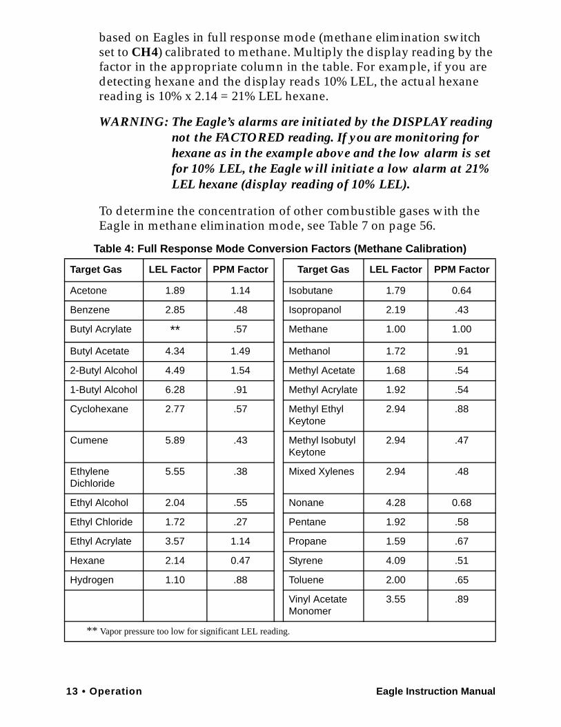
based on Eagles in full response mode (methane elimination switch set to CH4) calibrated to methane. Multiply the display reading by the factor in the appropriate column in the table. For example, if you are detecting hexane and the display reads 10% LEL, the actual hexane reading is 10% x 2.14 = 21% LEL hexane.
WARNING: The Eagle’s alarms are initiated by the DISPLAY reading not the FACTORED reading. If you are monitoring for hexane as in the example above and the low alarm is set for 10% LEL, the Eagle will initiate a low alarm at 21% LEL hexane (display reading of 10% LEL).
To determine the concentration of other combustible gases with the Eagle in methane elimination mode, see Table 7 on page 56.
Table 4: Full Response Mode Conversion Factors (Methane Calibration)
Target Gas LEL Factor PPM Factor Target Gas LEL Factor PPM Factor
Acetone 1.89 1.14 Isobutane 1.79 0.64
Benzene 2.85 .48 Isopropanol 2.19 .43
Butyl Acrylate ** .57 Methane 1.00 1.00
Butyl Acetate 4.34 1.49 Methanol 1.72 .91
2-Butyl Alcohol 4.49 1.54 Methyl Acetate 1.68 .54
1-Butyl Alcohol 6.28 .91 Methyl Acrylate 1.92 .54
Cyclohexane 2.77 .57 Methyl Ethyl Keytone
2.94 .88
Cumene 5.89 .43 Methyl Isobutyl Keytone
2.94 .47
Ethylene Dichloride
5.55 .38 Mixed Xylenes 2.94 .48
Ethyl Alcohol 2.04 .55 Nonane 4.28 0.68
Ethyl Chloride 1.72 .27 Pentane 1.92 .58
Ethyl Acrylate 3.57 1.14 Propane 1.59 .67
Hexane 2.14 0.47 Styrene 4.09 .51
Hydrogen 1.10 .88 Toluene 2.00 .65
Vinyl Acetate Monomer
3.55 .89
** Vapor pressure too low for significant LEL reading.
Eagle Instruction Manual Operation • 14
Setting User AccessThe CAL/SETUP switch controls the Eagle functions available to the user. The switch setting does not affect the Eagle’s ability to display gas readings and indicate gas and malfunction alarms.
1. Turn off the Eagle.
2. Unscrew the two large screws on the top of the case.
3. Turn over the top half of the case, and locate the CAL/SETUP switch (SW2) near the middle along one edge of the main processor board.
CAUTION:The Methane Elimination switch (SW1) is on the opposite edge of the board near the front end. DO NOT confuse these two switches.
4. Place the CAL/SETUP switch in the appropriate position.
• To give the Eagle access to all modes, place the switch in the ON position.
• To limit the Eagle to normal operating and display modes, place the switch in the OFF position. (The Eagle prevents access to the setup and calibration modes by disabling the SHIFT/▼ button.)
5. Place the top of the case in its original position, then secure it with the large screws you loosened in step 2.
6. Turn on the Eagle.
NOTE: Make sure the Eagle’s calibration is current and the setup options are appropriate and safe for the operating environment before placing the CAL/SETUP switch in the OFF position.
Turning Off the EagleTo turn off the Eagle, press and hold down the POWER/ENTER button until GOOD-BYE displays, then release the button. (You must wait for GOOD-BYE to disappear before you can turn on the Eagle again.)
15 • Alarms Eagle Instruction Manual
Alarms
Alarm IndicationsThis section describes the Eagle’s audible and visual alarm indications for gas, over range, low flow, low battery, and sensor failure alarms. This section also describes how to reset gas alarms.
The default alarm settings are listed in Table 2, “Standard Sensor Specifications” on page 4. The alarm settings are user-adjustable as described in “Updating the Alarm Point Settings” on page 33.
NOTE: The screens illustrated in this section are intended as examples only. The screens displayed by your Eagle model may be slightly different.
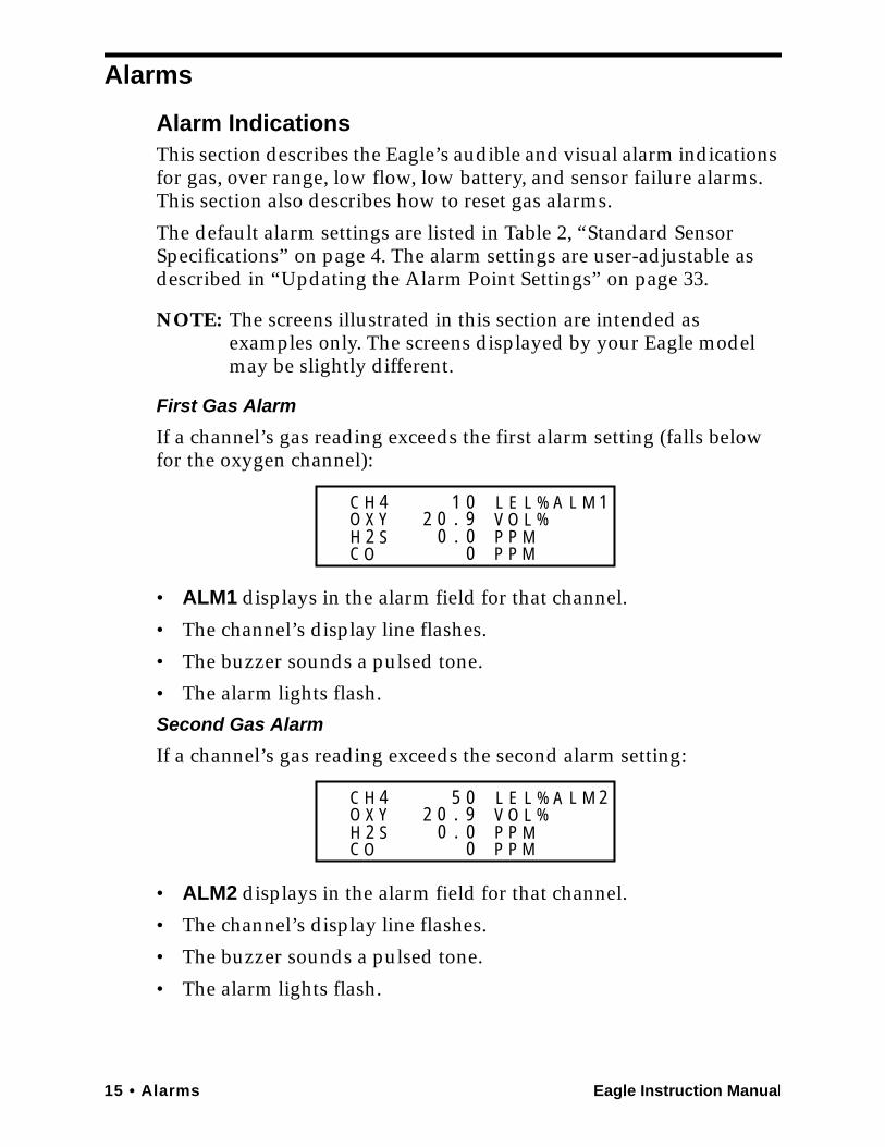
First Gas Alarm
If a channel’s gas reading exceeds the first alarm setting (falls below for the oxygen channel):
• ALM1 displays in the alarm field for that channel.
• The channel’s display line flashes.
• The buzzer sounds a pulsed tone.
• The alarm lights flash.
Second Gas Alarm
If a channel’s gas reading exceeds the second alarm setting:
• ALM2 displays in the alarm field for that channel.
• The channel’s display line flashes.
• The buzzer sounds a pulsed tone.
• The alarm lights flash.
C H 4O Y
C OH 2 S
X 2 0 . 90
00.0
LVPP
PP
MM
EO
LL
%%
A L M 11
C H 4O Y
C OH 2 S
X 2 0 . 90
00.0
LVPP
PP
MM
EO
LL
%%
A L M 25
Eagle Instruction Manual Alarms • 16
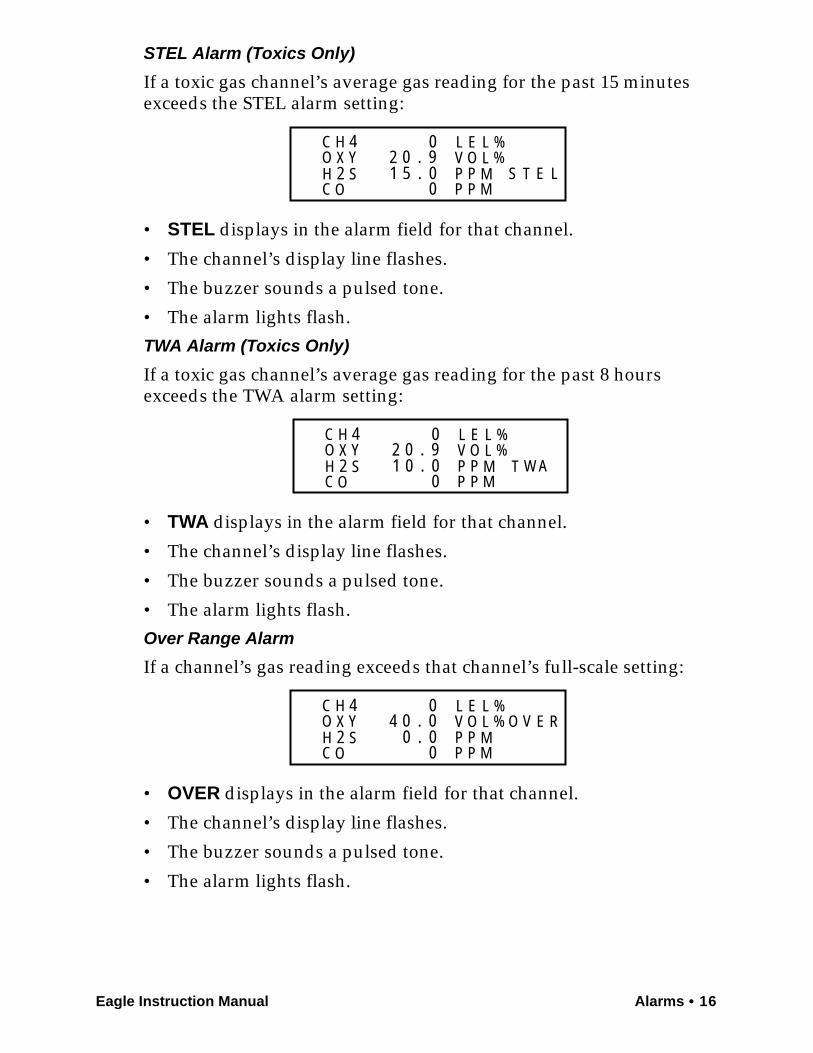
STEL Alarm (Toxics Only)
If a toxic gas channel’s average gas reading for the past 15 minutes exceeds the STEL alarm setting:
• STEL displays in the alarm field for that channel.
• The channel’s display line flashes.
• The buzzer sounds a pulsed tone.
• The alarm lights flash.
TWA Alarm (Toxics Only)
If a toxic gas channel’s average gas reading for the past 8 hours exceeds the TWA alarm setting:
• TWA displays in the alarm field for that channel.
• The channel’s display line flashes.
• The buzzer sounds a pulsed tone.
• The alarm lights flash.
Over Range Alarm
If a channel’s gas reading exceeds that channel’s full-scale setting:
• OVER displays in the alarm field for that channel.
• The channel’s display line flashes.
• The buzzer sounds a pulsed tone.
• The alarm lights flash.
C H 4O Y
C OH 2 S
X 2 0 . 90
00.5
LVPP
PP
MM
EO
LL
%%
S T E1 L
C H 4O Y
C OH 2 S
X 2 0 . 90
00.0
LVPP
PP
MM
EO
LL
%%
T W A1
C H 4O Y
C OH 2 S
X 4 0 . 00
00.0
LVPP
PP
MM
EO
LL
%% O V E R
17 • Alarms Eagle Instruction Manual
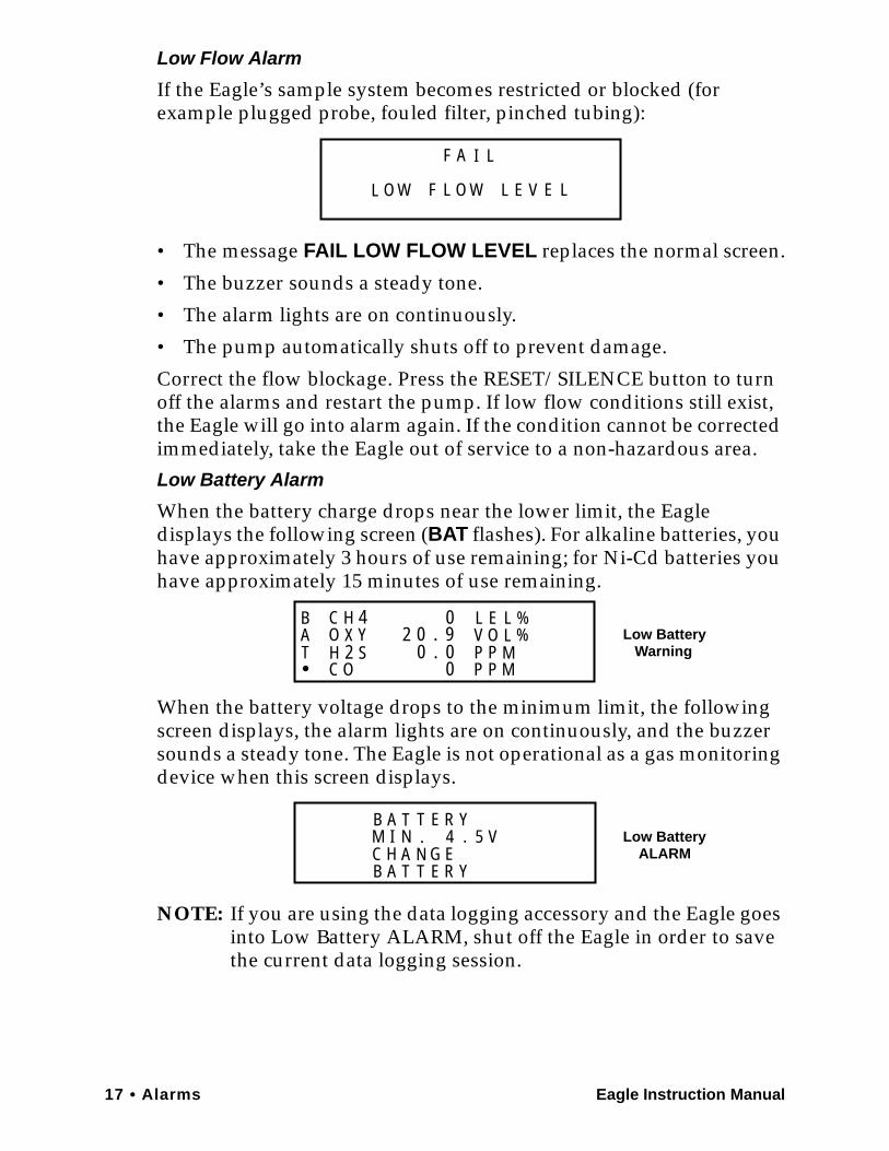
Low Flow Alarm
If the Eagle’s sample system becomes restricted or blocked (for example plugged probe, fouled filter, pinched tubing):
• The message FAIL LOW FLOW LEVEL replaces the normal screen.
• The buzzer sounds a steady tone.
• The alarm lights are on continuously.
• The pump automatically shuts off to prevent damage.
Correct the flow blockage. Press the RESET/SILENCE button to turn off the alarms and restart the pump. If low flow conditions still exist, the Eagle will go into alarm again. If the condition cannot be corrected immediately, take the Eagle out of service to a non-hazardous area.
Low Battery Alarm
When the battery charge drops near the lower limit, the Eagle displays the following screen (BAT flashes). For alkaline batteries, you have approximately 3 hours of use remaining; for Ni-Cd batteries you have approximately 15 minutes of use remaining.
When the battery voltage drops to the minimum limit, the following screen displays, the alarm lights are on continuously, and the buzzer sounds a steady tone. The Eagle is not operational as a gas monitoring device when this screen displays.
NOTE: If you are using the data logging accessory and the Eagle goes into Low Battery ALARM, shut off the Eagle in order to save the current data logging session.
F
F LL O W EL O W
A I L
L E V
C H 4O Y
C OH 2 S
X 2 0 . 90
00.0
LVPP
PP
MM
EO
LL
%%
BAT
Low BatteryWarning
B A T T E R YM I N . 4 . 5 V
B A T T E R YGC H NA E
Low BatteryALARM
Eagle Instruction Manual Alarms • 18
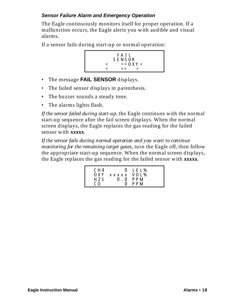
Sensor Failure Alarm and Emergency Operation
The Eagle continuously monitors itself for proper operation. If a malfunction occurs, the Eagle alerts you with audible and visual alarms.
If a sensor fails during start-up or normal operation:
• The message FAIL SENSOR displays.
• The failed sensor displays in parenthesis.
• The buzzer sounds a steady tone.
• The alarms lights flash.
If the sensor failed during start-up, the Eagle continues with the normalstart-up sequence after the fail screen displays. When the normal screen displays, the Eagle replaces the gas reading for the failed sensor with xxxxx.
If the sensor fails during normal operation and you want to continue monitoring for the remaining target gases, turn the Eagle off, then follow the appropriate start-up sequence. When the normal screen displays, the Eagle replaces the gas reading for the failed sensor with xxxxx.
> < O Y>
< X> <<
>
F A I LS E N S O R
C H 4O Y
C OH 2 S
X0
00.0
LVPP
PP
MM
EO
LL
%%x x xxx
19 • Alarms Eagle Instruction Manual
Resetting Gas AlarmsYou can set the Eagle’s gas alarms for latching or self-resetting alarms(see “Updating the Alarm Latching Setting” on page 35).
Self-Resetting Alarms
Self-resetting alarms automatically shut off and reset when the gas reading falls below (or rises above for oxygen) the alarm setting. You cannot silence or reset self-resetting alarms.
Latching Alarms
You can set latching alarms with or without Alarm Silence (see “Updating the Alarm Silence Setting” on page 35).With Alarm Silence On:
When the Eagle goes into gas alarm, press the RESET/SILENCE button to silence the buzzer. The LEDs continue to flash, and the Eagle continues to display the current alarm level.
The gas reading must fall below (or rise above for oxygen) the low alarm (ALM1) setting before you can reset the alarm. Press the RESET/SILENCE button to reset the alarm. The LEDs turn off and the Eagle returns to the normal screen.With Alarm Silence Off:
The gas reading must fall below (or rise above for oxygen) the low alarm (ALM1) setting before you can reset the alarm. Press the RESET/SILENCE button to reset the alarm. The LEDs and buzzer turn off, and the Eagle returns to the normal screen.
NOTE: With Alarm Silence off, you cannot silence the buzzer while the gas reading is above (below for oxygen) the low alarm (ALM1) setting.
Eagle Instruction Manual Display Mode • 20
Display Mode
The Eagle has four operating modes: normal operating mode, display mode, setup mode, and calibration mode. With the Eagle in display mode, you can:
• set user and station IDs
• display peak readings
• display elapsed time
• display TWA and STEL readings (toxic gases only)
• display battery voltage
• display date and time (data logging option only)
• clear the data log (data logging option only)
• display remaining log time (data logging option only)
To enter display mode, from the normal screen press the DISP/ADJ button. To scroll from one screen to the next press the DISP/ADJ button.
NOTE: Each screen displays for 20 seconds. If you do not press the DISP/ADJ button to scroll to the next screen within 20 seconds, the Eagle automatically returns to the normal operating screen.
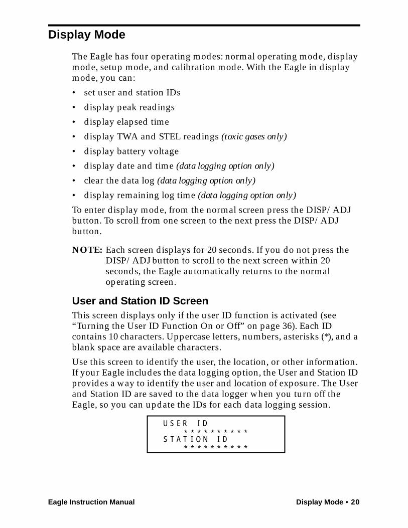
User and Station ID ScreenThis screen displays only if the user ID function is activated (see “Turning the User ID Function On or Off” on page 36). Each ID contains 10 characters. Uppercase letters, numbers, asterisks (*), and a blank space are available characters.
Use this screen to identify the user, the location, or other information. If your Eagle includes the data logging option, the User and Station ID provides a way to identify the user and location of exposure. The User and Station ID are saved to the data logger when you turn off the Eagle, so you can update the IDs for each data logging session.
S E R D
A T I OT IN D
U
S
I* * * * * * * * * *
* * * * * * * * * *
21 • Display Mode Eagle Instruction Manual
To enter a user and station ID:
To scroll to the next screen at any time, press the DISP/ADJ button.
1. Press the POWER/ENTER button. The first character under USER ID flashes (* is default).
2. Press the AIR/▲ and SHIFT/▼ buttons to scroll through the available characters. (The asterisk and blank space are between the set of letters and numbers.)
3. When the desired character displays, press the POWER/ENTER button to enter the character and go to the next character.
4. Repeat steps 2 and 3 for the remaining 19 characters.
After you enter the last character, the Peak screen displays.
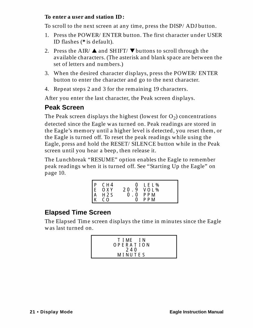
Peak ScreenThe Peak screen displays the highest (lowest for O2) concentrations detected since the Eagle was turned on. Peak readings are stored in the Eagle’s memory until a higher level is detected, you reset them, or the Eagle is turned off. To reset the peak readings while using the Eagle, press and hold the RESET/SILENCE button while in the Peak screen until you hear a beep, then release it.
The Lunchbreak “RESUME” option enables the Eagle to remember peak readings when it is turned off. See “Starting Up the Eagle” on page 10.
Elapsed Time ScreenThe Elapsed Time screen displays the time in minutes since the Eagle was last turned on.
C H 4O Y
C OH 2 S
X 2 0 . 90
00.0
LVPP
PP
MM
EO
LL
%%
PEAK
MR A I
M U
O NO P E TE NI
2SI N T E
T I
4 0
Eagle Instruction Manual Display Mode • 22
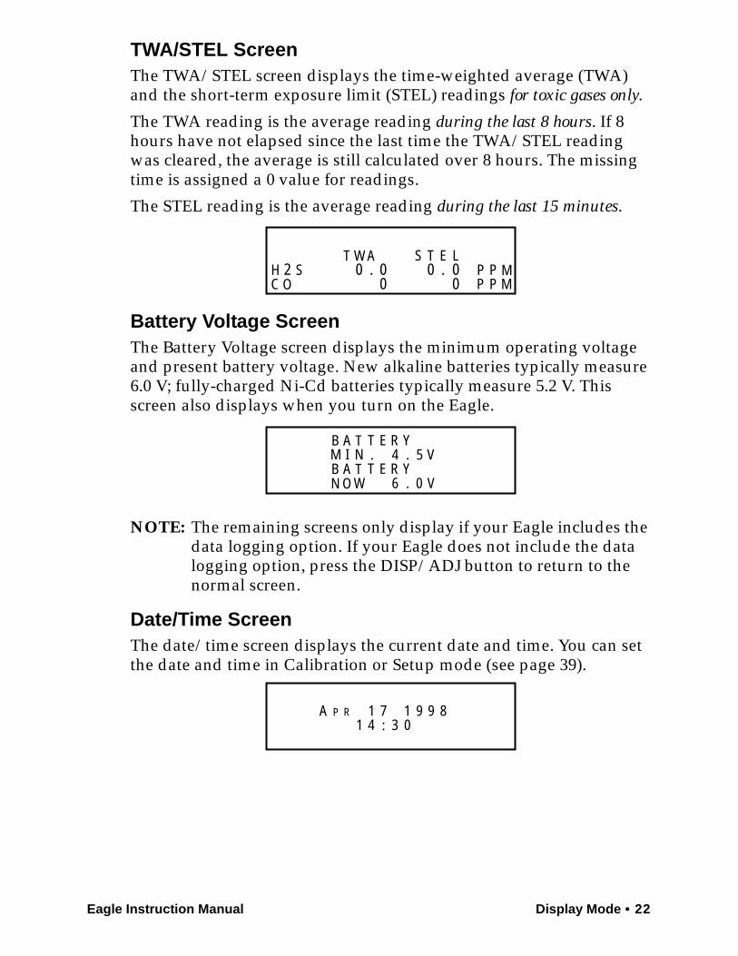
TWA/STEL ScreenThe TWA/STEL screen displays the time-weighted average (TWA) and the short-term exposure limit (STEL) readings for toxic gases only.
The TWA reading is the average reading during the last 8 hours. If 8 hours have not elapsed since the last time the TWA/STEL reading was cleared, the average is still calculated over 8 hours. The missing time is assigned a 0 value for readings.
The STEL reading is the average reading during the last 15 minutes.
Battery Voltage ScreenThe Battery Voltage screen displays the minimum operating voltage and present battery voltage. New alkaline batteries typically measure 6.0 V; fully-charged Ni-Cd batteries typically measure 5.2 V. This screen also displays when you turn on the Eagle.
NOTE: The remaining screens only display if your Eagle includes the data logging option. If your Eagle does not include the data logging option, press the DISP/ADJ button to return to the normal screen.
Date/Time ScreenThe date/time screen displays the current date and time. You can set the date and time in Calibration or Setup mode (see page 39).
W S
C O2 S
A
00.0 P
PPP
MM
TH
T E L0.00
B A T T E R YM I N . 4 . 5 VB A T T E R Y
6 0 V.N O W
PA 1 7 14 :
R 9 9 81 3 0
23 • Display Mode Eagle Instruction Manual
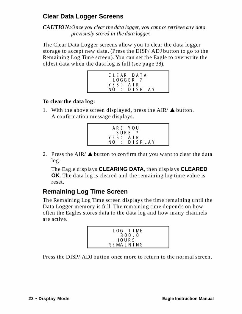
Clear Data Logger Screens
CAUTION:Once you clear the data logger, you cannot retrieve any data previously stored in the data logger.
The Clear Data Logger screens allow you to clear the data logger storage to accept new data. (Press the DISP/ADJ button to go to the Remaining Log Time screen). You can set the Eagle to overwrite the oldest data when the data log is full (see page 38).
To clear the data log:
1. With the above screen displayed, press the AIR/▲ button.A confirmation message displays.
2. Press the AIR/▲ button to confirm that you want to clear the data log.
The Eagle displays CLEARING DATA, then displays CLEARED OK. The data log is cleared and the remaining log time value is reset.
Remaining Log Time ScreenThe Remaining Log Time screen displays the time remaining until the Data Logger memory is full. The remaining time depends on how often the Eagles stores data to the data log and how many channels are active.
Press the DISP/ADJ button once more to return to the normal screen.
O GC R D
N IY E S
A A
A:
T
RS
ID
AEL
L E?
O P: L A Y
G R
S UY O
N IY E S
E U
A: RS
ID
EA R
?
O P: L A Y
R
3T I
R IH
G M
UO RN
SN
0L O
E GA IM
0E
0.
Eagle Instruction Manual Setup Mode • 24
Setup Mode
NOTE: The screens illustrated in this section are examples only. The screens displayed by your Eagle model may be slightly different.
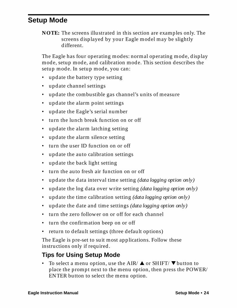
The Eagle has four operating modes: normal operating mode, display mode, setup mode, and calibration mode. This section describes the setup mode. In setup mode, you can:
• update the battery type setting
• update channel settings
• update the combustible gas channel’s units of measure
• update the alarm point settings
• update the Eagle’s serial number
• turn the lunch break function on or off
• update the alarm latching setting
• update the alarm silence setting
• turn the user ID function on or off
• update the auto calibration settings
• update the back light setting
• turn the auto fresh air function on or off
• update the data interval time setting (data logging option only)
• update the log data over write setting (data logging option only)
• update the time calibration setting (data logging option only)
• update the date and time settings (data logging option only)
• turn the zero follower on or off for each channel
• turn the confirmation beep on or off
• return to default settings (three default options)
The Eagle is pre-set to suit most applications. Follow these instructions only if required.
Tips for Using Setup Mode• To select a menu option, use the AIR/▲ or SHIFT/▼ button to
place the prompt next to the menu option, then press the POWER/ENTER button to select the menu option.
25 • Setup Mode Eagle Instruction Manual
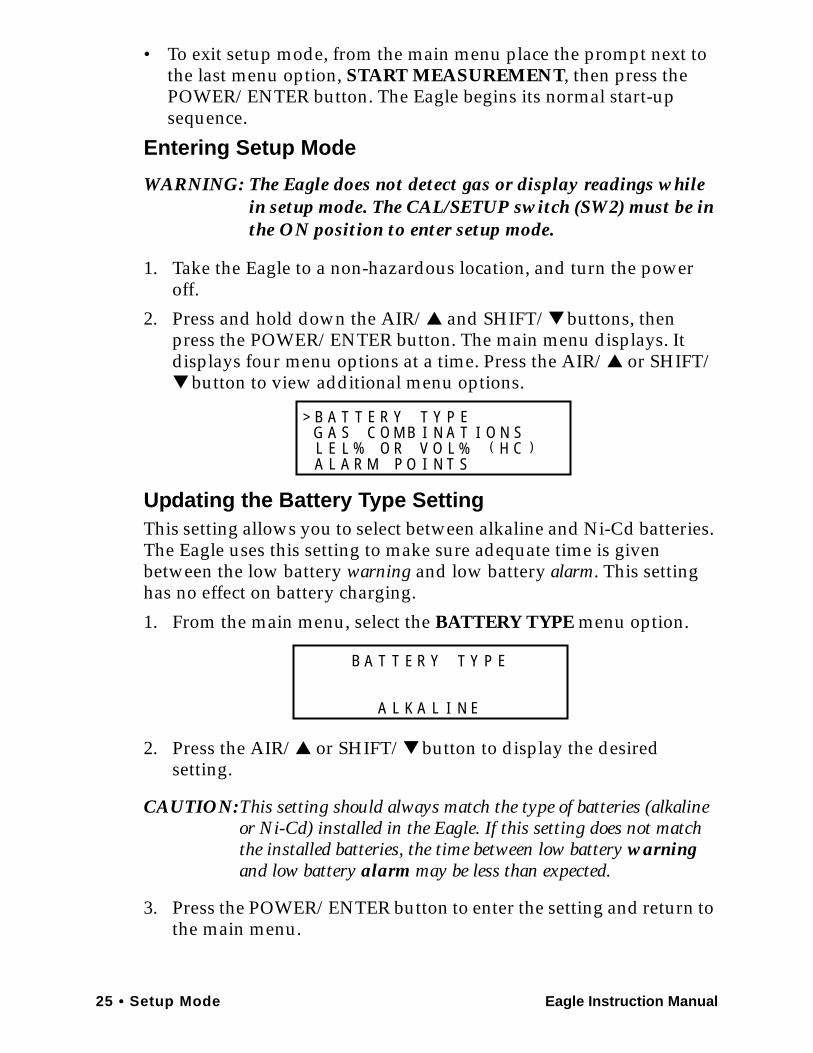
• To exit setup mode, from the main menu place the prompt next to the last menu option, START MEASUREMENT, then press the POWER/ENTER button. The Eagle begins its normal start-up sequence.
Entering Setup Mode
WARNING: The Eagle does not detect gas or display readings while in setup mode. The CAL/SETUP switch (SW2) must be in the ON position to enter setup mode.
1. Take the Eagle to a non-hazardous location, and turn the power off.
2. Press and hold down the AIR/▲ and SHIFT/▼ buttons, then press the POWER/ENTER button. The main menu displays. It displays four menu options at a time. Press the AIR/▲ or SHIFT/▼ button to view additional menu options.
Updating the Battery Type SettingThis setting allows you to select between alkaline and Ni-Cd batteries. The Eagle uses this setting to make sure adequate time is given between the low battery warning and low battery alarm. This setting has no effect on battery charging.
1. From the main menu, select the BATTERY TYPE menu option.
2. Press the AIR/▲ or SHIFT/▼ button to display the desired setting.
CAUTION:This setting should always match the type of batteries (alkaline or Ni-Cd) installed in the Eagle. If this setting does not match the installed batteries, the time between low battery warning and low battery alarm may be less than expected.
3. Press the POWER/ENTER button to enter the setting and return to the main menu.
M BB E R
M T% O R
T Y
O
T
%S
LN
YNO
A TII A
P EA SG C T O N S
L E L V ( H C )A L A R P O I
>
B E R
I
T Y T
NL
YA T P E
A EL K A

Eagle Instruction Manual Setup Mode • 26
Updating Channel SettingsThis procedure describes how to update channel settings for the combustible gas, oxygen, and toxic gas channels.
CAUTION:Verify that the correct sensor is installed before you update a channel’s settings.
Updating Combustible Gas Channel Settings
This section describes how to update the target gas label, set a custom gas label, and update the fullscale PPM setting for the combustible gas channel.Updating the Target Gas Label
1. From the main menu, select the GAS COMBINATIONS menu option.
2. Use the AIR/▲ or SHIFT/▼ button to place the prompt next to the combustible gas channel (in this example CH4).
3. Press the POWER/ENTER button. The combustible gas target gas label flashes. This indicates that this setting can now be updated.
4. Press the AIR/▲ or SHIFT/▼ buttons to display the available combustible gas target gas labels (CH4, HEX, H2, ***, and NOT USED).
NOTE: Select the HEX or *** setting for Methane Elimination(see “Appendix B: Methane Elimination” on page 55 for more information).
5. Press the POWER/ENTER button to enter the new target gas label.
A screen displays that shows the fullscale PPM setting, which corresponds to 100% LEL, and display increments for the target gas label you selected. If you select *** as the gas label, you must update the fullscale PPM setting to correspond to 100% LEL for the target gas.
C H 4O Y
C OH 2 S
X>

27 • Setup Mode Eagle Instruction Manual
The number in parenthesis indicates the display increment for that portion of the PPM range. In the example below, the PPM reading would display in increments of:
• 5 from 0 to 100 ppm
• 10 from 100 to 1000 PPM
• 50 from 1000 to 10,000 PPM
• 250 from 10,000 to 50,000 PPM
If you entered a label other than ***, continue with step 6. If you entered ***, go to the next section, “Setting a custom target gas label.”
6. Press the POWER/ENTER button to return to the Gas Combinations menu.
7. To exit the Gas Combinations menu, press the SHIFT/▼ button until the prompt is next to Channel 4, then press the SHIFT/▼ button again. The ESCAPE message displays.
8. Press the POWER/ENTER button. The message SAVING DATA displays, then the main menu displays.
Setting a Custom Target Gas Label
1. With the prompt next to the target gas label setting (***), press the POWER/ENTER button. The first asterisk flashes.
2. Press the AIR/▲ and SHIFT/▼ buttons to display the desired character. Available characters are A through Z, 0 through 9, and a blank space.
3. Press the POWER/ENTER button to enter the displayed character. The next character flashes.
4. Repeat steps 2 and 3 to enter the remaining characters. When you enter the last character, the prompt flashes.
Updating the Fullscale PPM Setting
CAUTION:The fullscale PPM setting must correspond to 100% LEL for the target gas in order for the Eagle to display accurate PPM readings for the combustible gas channel.
1. Press the SHIFT/▼ button to place the prompt in the second line, then press the POWER/ENTER button to update the fullscale
* * *5 0
(P
00
>0 0 P M
1 0 5 ) 01 0 0 0 ( 5 )001 0 0 ( 1 )0 5 00 0 0 ( 5 )02
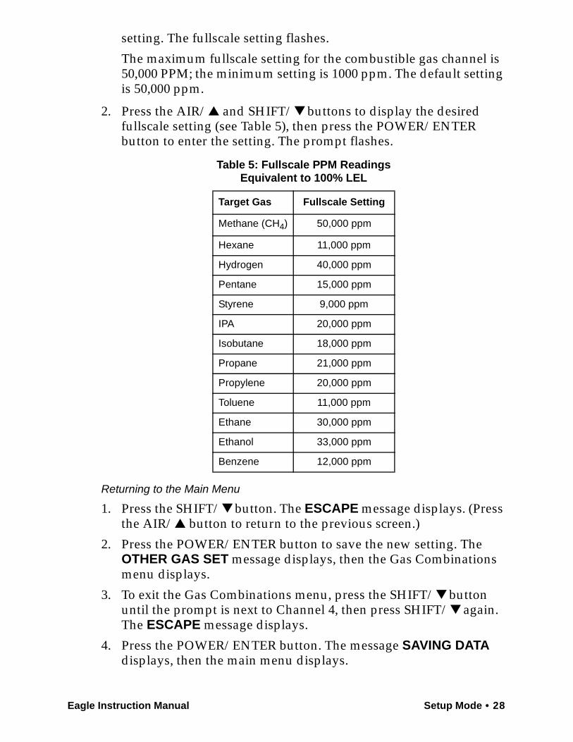
Eagle Instruction Manual Setup Mode • 28
setting. The fullscale setting flashes.
The maximum fullscale setting for the combustible gas channel is 50,000 PPM; the minimum setting is 1000 ppm. The default setting is 50,000 ppm.
2. Press the AIR/▲ and SHIFT/▼ buttons to display the desired fullscale setting (see Table 5), then press the POWER/ENTER button to enter the setting. The prompt flashes.
Returning to the Main Menu
1. Press the SHIFT/▼ button. The ESCAPE message displays. (Press the AIR/▲ button to return to the previous screen.)
2. Press the POWER/ENTER button to save the new setting. The OTHER GAS SET message displays, then the Gas Combinations menu displays.
3. To exit the Gas Combinations menu, press the SHIFT/▼ button until the prompt is next to Channel 4, then press SHIFT/▼ again. The ESCAPE message displays.
4. Press the POWER/ENTER button. The message SAVING DATA displays, then the main menu displays.
Table 5: Fullscale PPM ReadingsEquivalent to 100% LEL
Target Gas Fullscale Setting
Methane (CH4) 50,000 ppm
Hexane 11,000 ppm
Hydrogen 40,000 ppm
Pentane 15,000 ppm
Styrene 9,000 ppm
IPA 20,000 ppm
Isobutane 18,000 ppm
Propane 21,000 ppm
Propylene 20,000 ppm
Toluene 11,000 ppm
Ethane 30,000 ppm
Ethanol 33,000 ppm
Benzene 12,000 ppm
29 • Setup Mode Eagle Instruction Manual
Updating Oxygen Channel Settings
This section describes how to update the target gas label, fullscale setting, and display increment setting for the oxygen channel.Updating the Target Gas Label
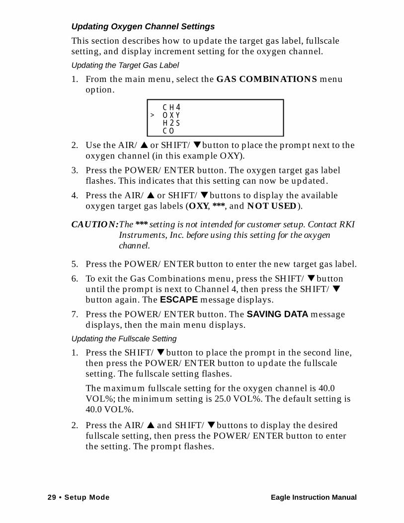
1. From the main menu, select the GAS COMBINATIONS menu option.
2. Use the AIR/▲ or SHIFT/▼ button to place the prompt next to the oxygen channel (in this example OXY).
3. Press the POWER/ENTER button. The oxygen target gas label flashes. This indicates that this setting can now be updated.
4. Press the AIR/▲ or SHIFT/▼ buttons to display the available oxygen target gas labels (OXY, ***, and NOT USED).
CAUTION:The *** setting is not intended for customer setup. Contact RKI Instruments, Inc. before using this setting for the oxygen channel.
5. Press the POWER/ENTER button to enter the new target gas label.
6. To exit the Gas Combinations menu, press the SHIFT/▼ button until the prompt is next to Channel 4, then press the SHIFT/▼ button again. The ESCAPE message displays.
7. Press the POWER/ENTER button. The SAVING DATA message displays, then the main menu displays.
Updating the Fullscale Setting
1. Press the SHIFT/▼ button to place the prompt in the second line, then press the POWER/ENTER button to update the fullscale setting. The fullscale setting flashes.
The maximum fullscale setting for the oxygen channel is 40.0 VOL%; the minimum setting is 25.0 VOL%. The default setting is 40.0 VOL%.
2. Press the AIR/▲ and SHIFT/▼ buttons to display the desired fullscale setting, then press the POWER/ENTER button to enter the setting. The prompt flashes.
C H 4O Y
C OH 2 S
X>
Eagle Instruction Manual Setup Mode • 30
Updating the Display Increment Setting
1. Press the SHIFT/▼ button to place the prompt in the third line, then press the POWER/ENTER button. The display increment setting flashes. The allowable settings are 0.2 VOL% (default) and 0.5 VOL%.
2. Press the AIR/▲ or SHIFT/▼ button to display the desired display increment setting, then press the POWER/ENTER button to enter the setting. The prompt flashes.
Returning to the Main Menu
1. Press the SHIFT/▼ button. The ESCAPE message displays. (Press the AIR/▲ button to return to the previous screen.)
2. Press the POWER/ENTER button to save the new settings. The OTHER GAS SET message displays, then the Gas Combinations menu displays.
3. To exit the Gas Combinations menu, press the SHIFT/▼ button until the prompt is next to Channel 4, then press the SHIFT/▼ button again. The ESCAPE message displays.
4. Press the POWER/ENTER button. The message SAVING DATA displays, then the main menu displays.
Updating Toxic Channel Settings
This section describes how to update the target gas label, set a custom gas label, and update the fullscale and display increment settings for a toxic gas channel.Updating the Target Gas Label
1. From the main menu, select the GAS COMBINATIONS menu option.
2. Press the POWER/ENTER button to display the Gas Combinations menu.
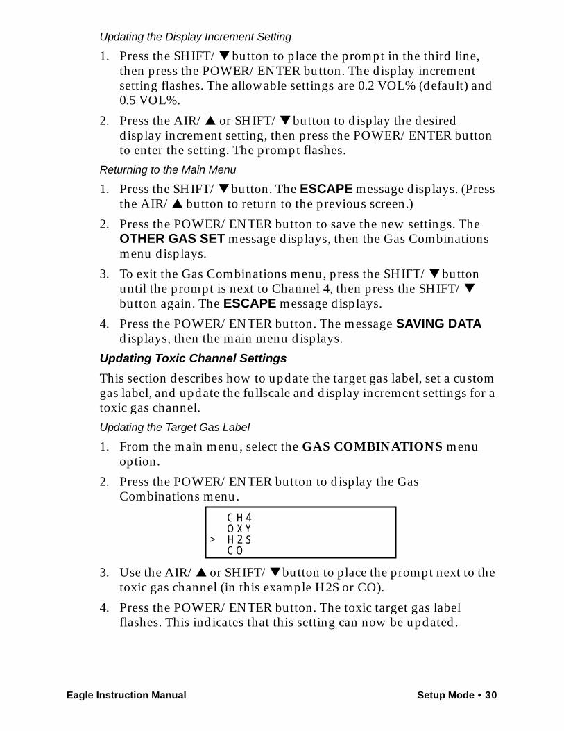
3. Use the AIR/▲ or SHIFT/▼ button to place the prompt next to the toxic gas channel (in this example H2S or CO).
4. Press the POWER/ENTER button. The toxic target gas label flashes. This indicates that this setting can now be updated.
C H 4O Y
C OH 2 S
X>
31 • Setup Mode Eagle Instruction Manual
5. Press the AIR/▲ or SHIFT/▼ buttons to display the available target gas labels for the toxic gas channel (H2S, CO, SO2, Cl2, NH3, CO2 (5.00%), CO2 (10000 PPM), CO2 (5000 PPM), ***, and NOT USED).
6. Press the POWER/ENTER button to enter the new target gas label.
If you entered a label other than ***, continue with step 7. If you entered ***, go to the next section, “Setting a custom target gas label.”
7. To exit the Gas Combinations menu, press the SHIFT/▼ button until the prompt is next to Channel 4, then press the SHIFT/▼ button again. The ESCAPE message displays.
8. Press the POWER/ENTER button. The message SAVING DATA displays, then the main menu displays.
Setting a Custom Target Gas Label
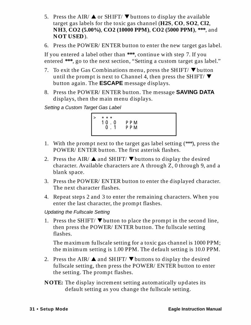
1. With the prompt next to the target gas label setting (***), press the POWER/ENTER button. The first asterisk flashes.
2. Press the AIR/▲ and SHIFT/▼ buttons to display the desired character. Available characters are A through Z, 0 through 9, and a blank space.
3. Press the POWER/ENTER button to enter the displayed character. The next character flashes.
4. Repeat steps 2 and 3 to enter the remaining characters. When you enter the last character, the prompt flashes.
Updating the Fullscale Setting
1. Press the SHIFT/▼ button to place the prompt in the second line, then press the POWER/ENTER button. The fullscale setting flashes.
The maximum fullscale setting for a toxic gas channel is 1000 PPM; the minimum setting is 1.00 PPM. The default setting is 10.0 PPM.
2. Press the AIR/▲ and SHIFT/▼ buttons to display the desired fullscale setting, then press the POWER/ENTER button to enter the setting. The prompt flashes.
NOTE: The display increment setting automatically updates its default setting as you change the fullscale setting.
* * *1 . P
00
>0 P M1. P P M
Eagle Instruction Manual Setup Mode • 32
Updating the Display Increment Setting
1. Press the SHIFT/▼ button to place the prompt in the third line, then press the POWER/ENTER button. The display increment setting flashes.The minimum display increment setting is 0.1 PPM; the maximum display increment setting is 2.5 PPM.
2. Press the AIR/▲ and SHIFT/▼ buttons to display the desired display increment setting, then press the POWER/ENTER button to enter the setting. The prompt flashes.
Returning to the Main Menu
1. Press the SHIFT/▼ button. The ESCAPE message displays. (Press the AIR/▲ button to return to the previous screen.)
2. Press the POWER/ENTER button to save the new settings. The OTHER GAS SET message displays, then the Gas Combinations menu displays.
3. To exit the Gas Combinations menu, press the SHIFT/▼ button until the prompt is next to Channel 4, then press the SHIFT/▼ button again. The ESCAPE message displays.
4. Press the POWER/ENTER button. The message SAVING DATA displays, then the main menu displays.
Updating Combustible Gas Channel Units of MeasureThis setting allows you to display the combustible gas reading in percentage of LEL or percentage of volume. The detection range remains the same. If 100% LEL equals 5% by volume, then fullscale on the volumetric display is 5%.
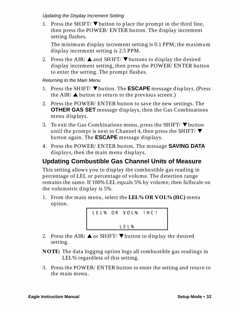
1. From the main menu, select the LEL% OR VOL% (HC) menu option.
2. Press the AIR/▲ or SHIFT/▼ button to display the desired setting.
NOTE: The data logging option logs all combustible gas readings in LEL% regardless of this setting.
3. Press the POWER/ENTER button to enter the setting and return to the main menu.
% O R O %LL E L V ( H C )
%L E L
33 • Setup Mode Eagle Instruction Manual
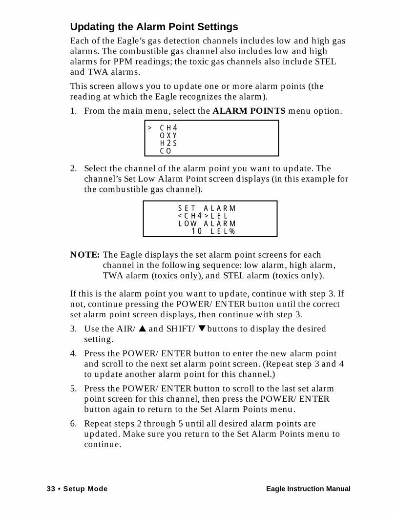
Updating the Alarm Point SettingsEach of the Eagle’s gas detection channels includes low and high gas alarms. The combustible gas channel also includes low and high alarms for PPM readings; the toxic gas channels also include STEL and TWA alarms.
This screen allows you to update one or more alarm points (the reading at which the Eagle recognizes the alarm).
1. From the main menu, select the ALARM POINTS menu option.
2. Select the channel of the alarm point you want to update. The channel’s Set Low Alarm Point screen displays (in this example for the combustible gas channel).
NOTE: The Eagle displays the set alarm point screens for each channel in the following sequence: low alarm, high alarm, TWA alarm (toxics only), and STEL alarm (toxics only).
If this is the alarm point you want to update, continue with step 3. If not, continue pressing the POWER/ENTER button until the correct set alarm point screen displays, then continue with step 3.
3. Use the AIR/▲ and SHIFT/▼ buttons to display the desired setting.
4. Press the POWER/ENTER button to enter the new alarm point and scroll to the next set alarm point screen. (Repeat step 3 and 4 to update another alarm point for this channel.)
5. Press the POWER/ENTER button to scroll to the last set alarm point screen for this channel, then press the POWER/ENTER button again to return to the Set Alarm Points menu.
6. Repeat steps 2 through 5 until all desired alarm points are updated. Make sure you return to the Set Alarm Points menu to continue.
C H 4O Y
C OH 2 S
X>
H 4S E
EO W
MT
L
A
RL
AL
LLC > E
A R< LL A M
1 0 %
Eagle Instruction Manual Setup Mode • 34
7. To exit the Set Alarm Points menu, press the SHIFT/▼ button until the prompt is next to Channel 4, then press the SHIFT/▼ button again. The ESCAPE message displays. (Press the AIR/▲ button if you want to return to the Set Alarm Points menu.
8. Press the POWER/ENTER button to save the settings and return to the main menu.
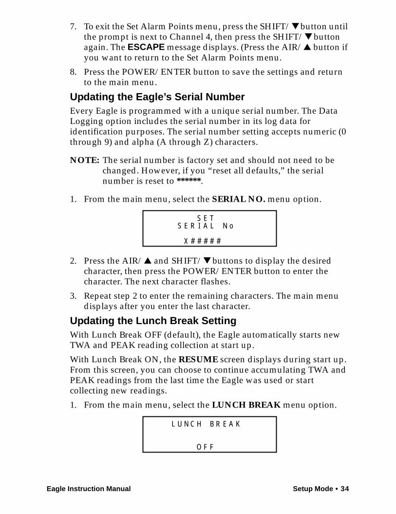
Updating the Eagle’s Serial NumberEvery Eagle is programmed with a unique serial number. The Data Logging option includes the serial number in its log data for identification purposes. The serial number setting accepts numeric (0 through 9) and alpha (A through Z) characters.
NOTE: The serial number is factory set and should not need to be changed. However, if you “reset all defaults,” the serial number is reset to ******.
1. From the main menu, select the SERIAL NO. menu option.
2. Press the AIR/▲ and SHIFT/▼ buttons to display the desired character, then press the POWER/ENTER button to enter the character. The next character flashes.
3. Repeat step 2 to enter the remaining characters. The main menu displays after you enter the last character.
Updating the Lunch Break SettingWith Lunch Break OFF (default), the Eagle automatically starts new TWA and PEAK reading collection at start up.
With Lunch Break ON, the RESUME screen displays during start up. From this screen, you can choose to continue accumulating TWA and PEAK readings from the last time the Eagle was used or start collecting new readings.
1. From the main menu, select the LUNCH BREAK menu option.
S E
X
E NTLR oI A
##
S
# # #
H R
F
U KB AN C EL
FO
35 • Setup Mode Eagle Instruction Manual
2. Press the AIR/▲ or SHIFT/▼ button to display the desired setting.
3. Press the POWER/ENTER button to enter the setting and return to the main menu.
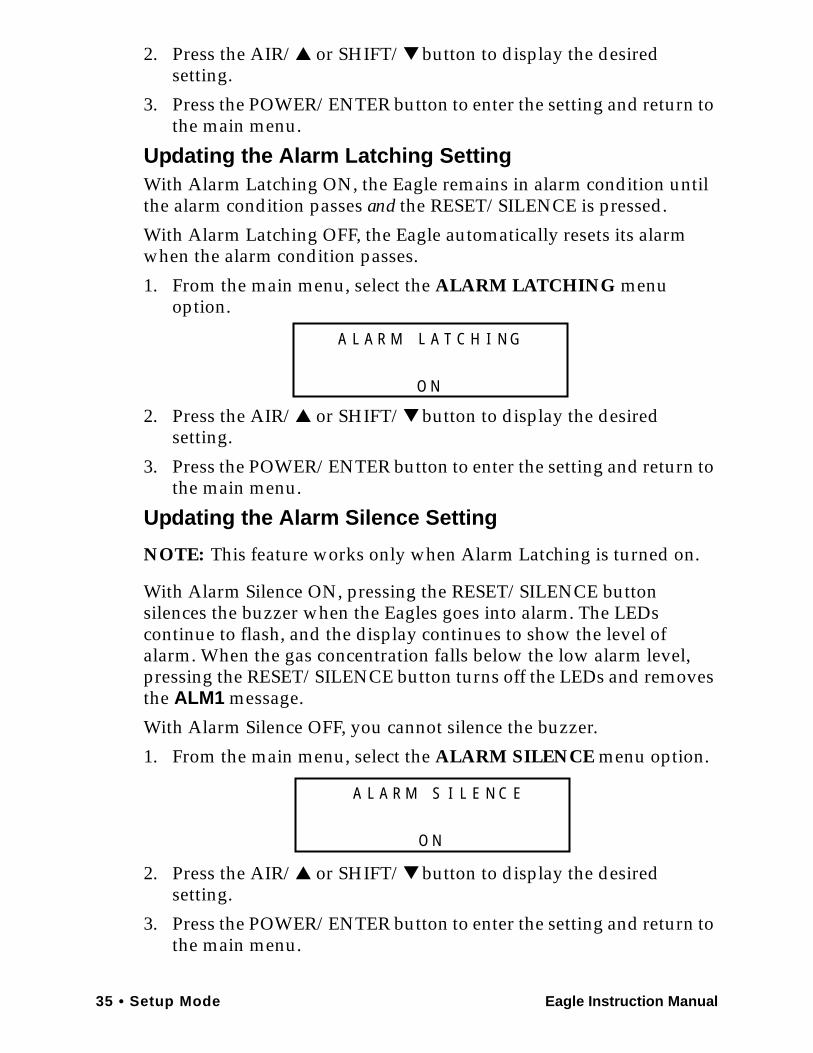
Updating the Alarm Latching SettingWith Alarm Latching ON, the Eagle remains in alarm condition until the alarm condition passes and the RESET/SILENCE is pressed.
With Alarm Latching OFF, the Eagle automatically resets its alarm when the alarm condition passes.
1. From the main menu, select the ALARM LATCHING menu option.
2. Press the AIR/▲ or SHIFT/▼ button to display the desired setting.
3. Press the POWER/ENTER button to enter the setting and return to the main menu.
Updating the Alarm Silence Setting
NOTE: This feature works only when Alarm Latching is turned on.
With Alarm Silence ON, pressing the RESET/SILENCE button silences the buzzer when the Eagles goes into alarm. The LEDs continue to flash, and the display continues to show the level of alarm. When the gas concentration falls below the low alarm level, pressing the RESET/SILENCE button turns off the LEDs and removes the ALM1 message.
With Alarm Silence OFF, you cannot silence the buzzer.
1. From the main menu, select the ALARM SILENCE menu option.
2. Press the AIR/▲ or SHIFT/▼ button to display the desired setting.
3. Press the POWER/ENTER button to enter the setting and return to the main menu.
L T
N
A IA HR M CL
O
A N G
I
N
A NS ER M LL
O
A C E
Eagle Instruction Manual Setup Mode • 36
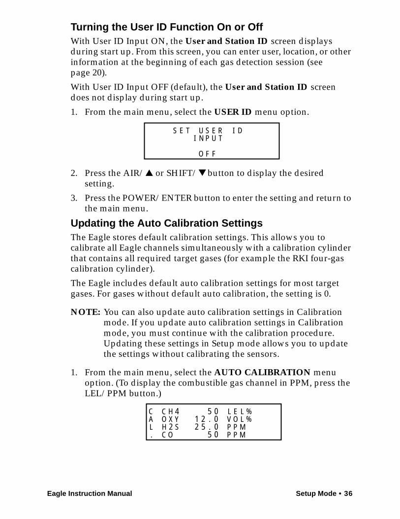
Turning the User ID Function On or OffWith User ID Input ON, the User and Station ID screen displays during start up. From this screen, you can enter user, location, or other information at the beginning of each gas detection session (see page 20).
With User ID Input OFF (default), the User and Station ID screen does not display during start up.
1. From the main menu, select the USER ID menu option.
2. Press the AIR/▲ or SHIFT/▼ button to display the desired setting.
3. Press the POWER/ENTER button to enter the setting and return to the main menu.
Updating the Auto Calibration SettingsThe Eagle stores default calibration settings. This allows you to calibrate all Eagle channels simultaneously with a calibration cylinder that contains all required target gases (for example the RKI four-gas calibration cylinder).
The Eagle includes default auto calibration settings for most target gases. For gases without default auto calibration, the setting is 0.
NOTE: You can also update auto calibration settings in Calibration mode. If you update auto calibration settings in Calibration mode, you must continue with the calibration procedure. Updating these settings in Setup mode allows you to update the settings without calibrating the sensors.
1. From the main menu, select the AUTO CALIBRATION menu option. (To display the combustible gas channel in PPM, press the LEL/PPM button.)
R
F
T DE ISUE
F
SI N P U T
O
C H 4O Y
C OH 2 S
X 1 2 . 00
00.5
LVPP
PP
MM
EO
LL
%%
CAL.
5
25
37 • Setup Mode Eagle Instruction Manual
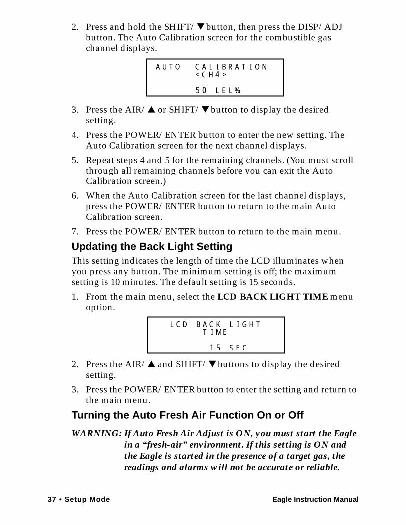
2. Press and hold the SHIFT/▼ button, then press the DISP/ADJ button. The Auto Calibration screen for the combustible gas channel displays.
3. Press the AIR/▲ or SHIFT/▼ button to display the desired setting.
4. Press the POWER/ENTER button to enter the new setting. The Auto Calibration screen for the next channel displays.
5. Repeat steps 4 and 5 for the remaining channels. (You must scroll through all remaining channels before you can exit the Auto Calibration screen.)
6. When the Auto Calibration screen for the last channel displays, press the POWER/ENTER button to return to the main Auto Calibration screen.
7. Press the POWER/ENTER button to return to the main menu.
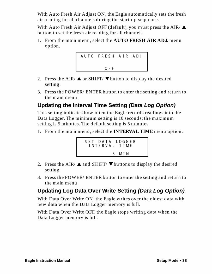
Updating the Back Light SettingThis setting indicates the length of time the LCD illuminates when you press any button. The minimum setting is off; the maximum setting is 10 minutes. The default setting is 15 seconds.
1. From the main menu, select the LCD BACK LIGHT TIME menu option.
2. Press the AIR/▲ and SHIFT/▼ buttons to display the desired setting.
3. Press the POWER/ENTER button to enter the setting and return to the main menu.
Turning the Auto Fresh Air Function On or Off
WARNING: If Auto Fresh Air Adjust is ON, you must start the Eagle in a “fresh-air” environment. If this setting is ON and the Eagle is started in the presence of a target gas, the readings and alarms will not be accurate or reliable.
A AC
E
O L I
LL
U T
%
B R A T I O N< C H 4 >
5 0
K
5
D GC IABC
C
L
S
T I M E
E
L H T
1
Eagle Instruction Manual Setup Mode • 38
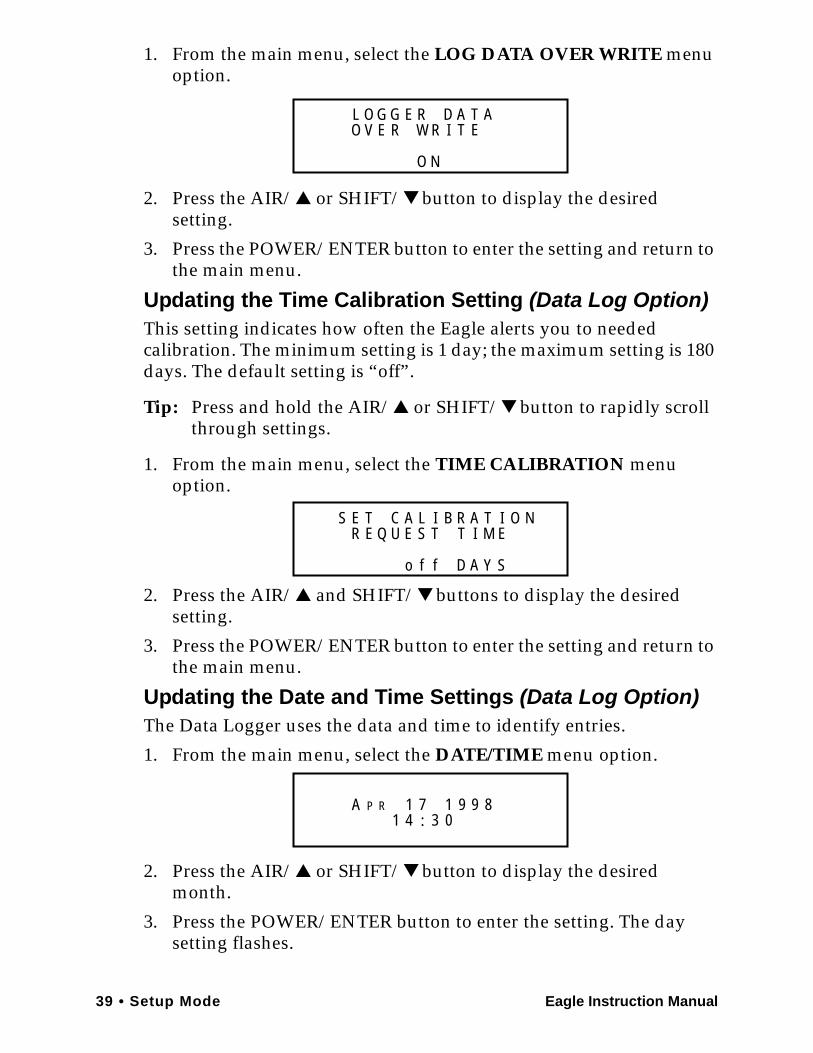
With Auto Fresh Air Adjust ON, the Eagle automatically sets the fresh air reading for all channels during the start-up sequence.
With Auto Fresh Air Adjust OFF (default), you must press the AIR/▲ button to set the fresh air reading for all channels.
1. From the main menu, select the AUTO FRESH AIR ADJ. menu option.
2. Press the AIR/▲ or SHIFT/▼ button to display the desired setting.
3. Press the POWER/ENTER button to enter the setting and return to the main menu.
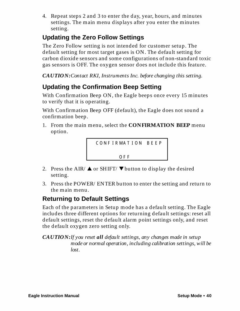
Updating the Interval Time Setting (Data Log Option)This setting indicates how often the Eagle records readings into the Data Logger. The minimum setting is 10 seconds; the maximum setting is 5 minutes. The default setting is 5 minutes.
1. From the main menu, select the INTERVAL TIME menu option.
2. Press the AIR/▲ and SHIFT/▼ buttons to display the desired setting.
3. Press the POWER/ENTER button to enter the setting and return to the main menu.
Updating Log Data Over Write Setting (Data Log Option)With Data Over Write ON, the Eagle writes over the oldest data with new data when the Data Logger memory is full.
With Data Over Write OFF, the Eagle stops writing data when the Data Logger memory is full.
S D
F
E RH IF R AO
F
T JAA U .
O
A
5
T GT GADE
N
S
M
T I M E
I
O E RLI N T E R A LV
39 • Setup Mode Eagle Instruction Manual
1. From the main menu, select the LOG DATA OVER WRITE menu option.
2. Press the AIR/▲ or SHIFT/▼ button to display the desired setting.
3. Press the POWER/ENTER button to enter the setting and return to the main menu.
Updating the Time Calibration Setting (Data Log Option)This setting indicates how often the Eagle alerts you to needed calibration. The minimum setting is 1 day; the maximum setting is 180 days. The default setting is “off”.
Tip: Press and hold the AIR/▲ or SHIFT/▼ button to rapidly scroll through settings.
1. From the main menu, select the TIME CALIBRATION menu option.
2. Press the AIR/▲ and SHIFT/▼ buttons to display the desired setting.
3. Press the POWER/ENTER button to enter the setting and return to the main menu.
Updating the Date and Time Settings (Data Log Option)The Data Logger uses the data and time to identify entries.
1. From the main menu, select the DATE/TIME menu option.
2. Press the AIR/▲ or SHIFT/▼ button to display the desired month.
3. Press the POWER/ENTER button to enter the setting. The day setting flashes.
RL AE TGG
N
O
O
T EAD
O V E R W R I
L TA AC I
Y
TES
D
T I M E
A
R I OBR E Q U S TE
N
Sffo
PA 1 7 14 :
R 9 9 81 3 0
Eagle Instruction Manual Setup Mode • 40
4. Repeat steps 2 and 3 to enter the day, year, hours, and minutes settings. The main menu displays after you enter the minutes setting.
Updating the Zero Follow SettingsThe Zero Follow setting is not intended for customer setup. The default setting for most target gases is ON. The default setting for carbon dioxide sensors and some configurations of non-standard toxic gas sensors is OFF. The oxygen sensor does not include this feature.
CAUTION:Contact RKI, Instruments Inc. before changing this setting.
Updating the Confirmation Beep SettingWith Confirmation Beep ON, the Eagle beeps once every 15 minutes to verify that it is operating.
With Confirmation Beep OFF (default), the Eagle does not sound a confirmation beep.
1. From the main menu, select the CONFIRMATION BEEP menu option.
2. Press the AIR/▲ or SHIFT/▼ button to display the desired setting.
3. Press the POWER/ENTER button to enter the setting and return to the main menu.
Returning to Default SettingsEach of the parameters in Setup mode has a default setting. The Eagle includes three different options for returning default settings: reset all default settings, reset the default alarm point settings only, and reset the default oxygen zero setting only.
CAUTION: If you reset all default settings, any changes made in setup mode or normal operation, including calibration settings, will be lost.
A E
F
M NT II R ON
F
O PEFC
O
B
41 • Setup Mode Eagle Instruction Manual
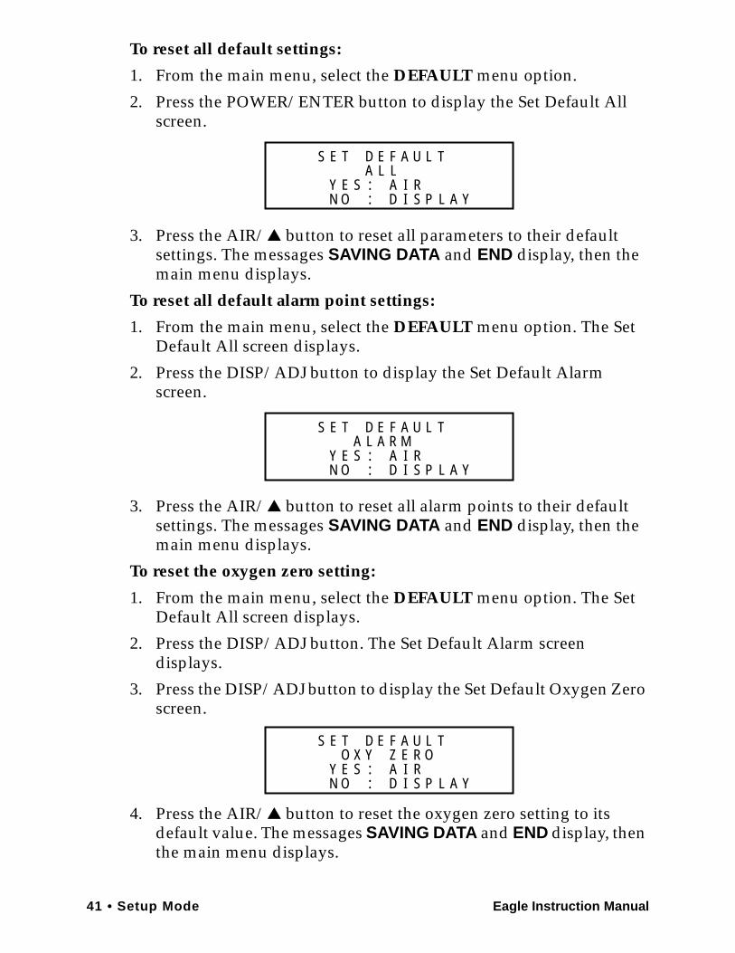
To reset all default settings:
1. From the main menu, select the DEFAULT menu option.
2. Press the POWER/ENTER button to display the Set Default All screen.
3. Press the AIR/▲ button to reset all parameters to their default settings. The messages SAVING DATA and END display, then the main menu displays.
To reset all default alarm point settings:
1. From the main menu, select the DEFAULT menu option. The Set Default All screen displays.
2. Press the DISP/ADJ button to display the Set Default Alarm screen.
3. Press the AIR/▲ button to reset all alarm points to their default settings. The messages SAVING DATA and END display, then the main menu displays.
To reset the oxygen zero setting:
1. From the main menu, select the DEFAULT menu option. The Set Default All screen displays.
2. Press the DISP/ADJ button. The Set Default Alarm screen displays.
3. Press the DISP/ADJ button to display the Set Default Oxygen Zero screen.
4. Press the AIR/▲ button to reset the oxygen zero setting to its default value. The messages SAVING DATA and END display, then the main menu displays.
AF A
N IY E S
D U
A: RS
ID
LT E
O P: L A Y
LS E TL
LF A
N IY E S
D U
A: RS
ID
RT E
O P: L A Y
AS E TL
A M
YF A
N IY E S
D U
A: RS
ID
ZT E
O P: L A Y
RS E TL
X EO O
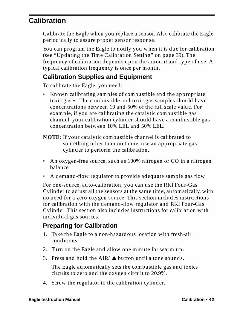
Eagle Instruction Manual Calibration • 42
Calibration
Calibrate the Eagle when you replace a sensor. Also calibrate the Eagle periodically to assure proper sensor response.
You can program the Eagle to notify you when it is due for calibration(see “Updating the Time Calibration Setting” on page 39). The frequency of calibration depends upon the amount and type of use. A typical calibration frequency is once per month.
Calibration Supplies and EquipmentTo calibrate the Eagle, you need:
• Known calibrating samples of combustible and the appropriate toxic gases. The combustible and toxic gas samples should have concentrations between 10 and 50% of the full scale value. For example, if you are calibrating the catalytic combustible gas channel, your calibration cylinder should have a combustible gas concentration between 10% LEL and 50% LEL.
NOTE: If your catalytic combustible channel is calibrated to something other than methane, use an appropriate gas cylinder to perform the calibration.
• An oxygen-free source, such as 100% nitrogen or CO in a nitrogen balance
• A demand-flow regulator to provide adequate sample gas flow
For one-source, auto-calibration, you can use the RKI Four-Gas Cylinder to adjust all the sensors at the same time, automatically, with no need for a zero-oxygen source. This section includes instructions for calibration with the demand-flow regulator and RKI Four-Gas Cylinder. This section also includes instructions for calibration with individual gas sources.
Preparing for Calibration1. Take the Eagle to a non-hazardous location with fresh-air
conditions.
2. Turn on the Eagle and allow one minute for warm up.
3. Press and hold the AIR/▲ button until a tone sounds.
The Eagle automatically sets the combustible gas and toxics circuits to zero and the oxygen circuit to 20.9%.
4. Screw the regulator to the calibration cylinder.
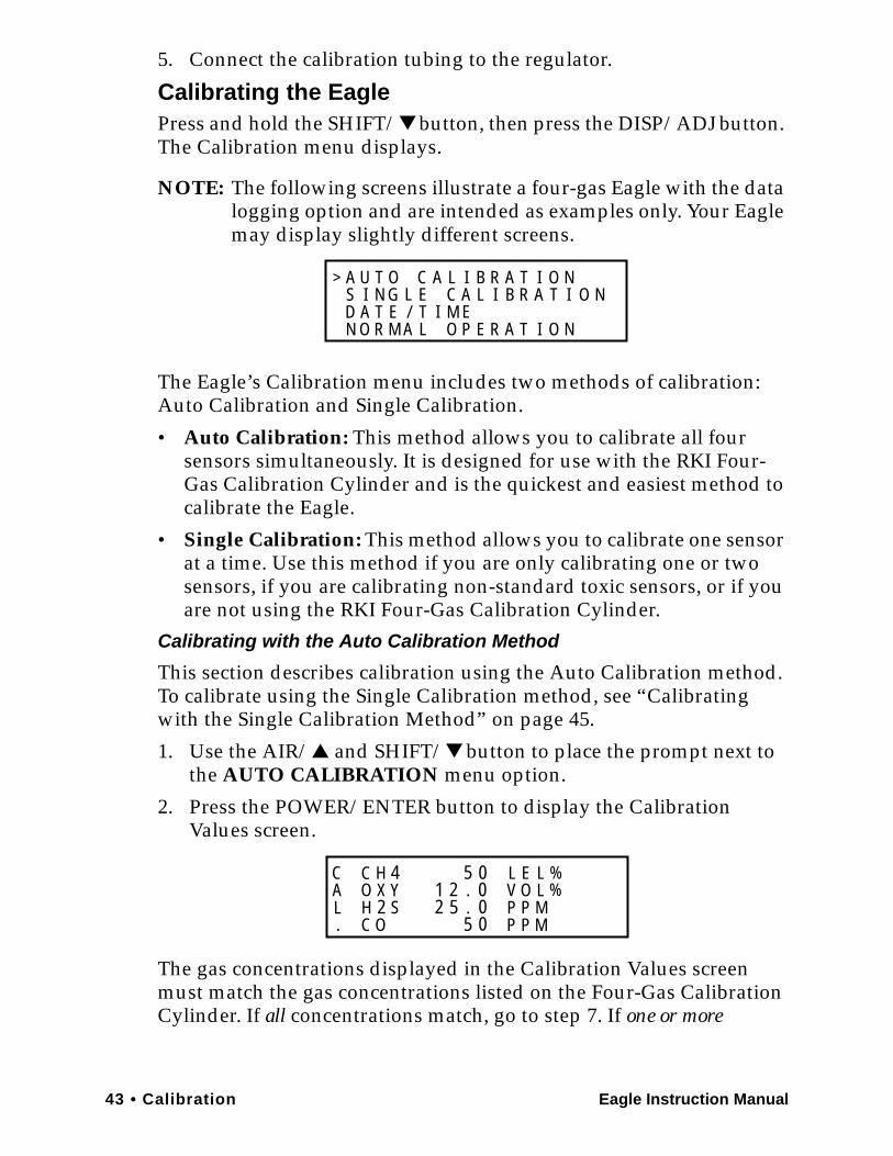
43 • Calibration Eagle Instruction Manual
5. Connect the calibration tubing to the regulator.
Calibrating the EaglePress and hold the SHIFT/▼ button, then press the DISP/ADJ button. The Calibration menu displays.
NOTE: The following screens illustrate a four-gas Eagle with the data logging option and are intended as examples only. Your Eagle may display slightly different screens.
The Eagle’s Calibration menu includes two methods of calibration:Auto Calibration and Single Calibration.
• Auto Calibration: This method allows you to calibrate all four sensors simultaneously. It is designed for use with the RKI Four-Gas Calibration Cylinder and is the quickest and easiest method to calibrate the Eagle.
• Single Calibration: This method allows you to calibrate one sensor at a time. Use this method if you are only calibrating one or two sensors, if you are calibrating non-standard toxic sensors, or if you are not using the RKI Four-Gas Calibration Cylinder.
Calibrating with the Auto Calibration Method
This section describes calibration using the Auto Calibration method.To calibrate using the Single Calibration method, see “Calibrating with the Single Calibration Method” on page 45.
1. Use the AIR/▲ and SHIFT/▼ button to place the prompt next to the AUTO CALIBRATION menu option.
2. Press the POWER/ENTER button to display the Calibration Values screen.
The gas concentrations displayed in the Calibration Values screen must match the gas concentrations listed on the Four-Gas Calibration Cylinder. If all concentrations match, go to step 7. If one or more
A AC
A RE MI
O L
T
I
IA OE
GU TI NS L
D A T ENN O R M L O P
>
/T
B R A T I O NE C A L I B R A T I O N
C H 4O Y
C OH 2 S
X 1 2 . 00
00.5
LVPP
PP
MM
EO
LL
%%
CAL.
5
25
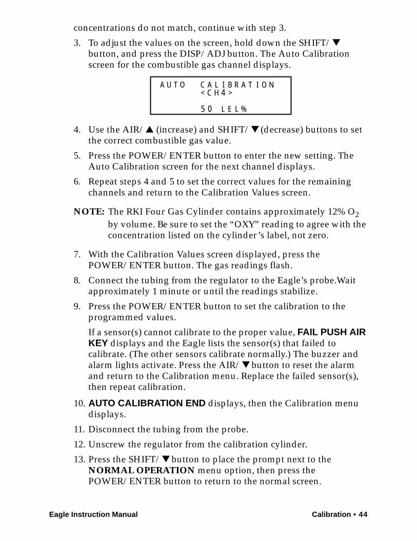
Eagle Instruction Manual Calibration • 44
concentrations do not match, continue with step 3.
3. To adjust the values on the screen, hold down the SHIFT/▼ button, and press the DISP/ADJ button. The Auto Calibration screen for the combustible gas channel displays.
4. Use the AIR/▲ (increase) and SHIFT/▼ (decrease) buttons to set the correct combustible gas value.
5. Press the POWER/ENTER button to enter the new setting. The Auto Calibration screen for the next channel displays.
6. Repeat steps 4 and 5 to set the correct values for the remaining channels and return to the Calibration Values screen.
NOTE: The RKI Four Gas Cylinder contains approximately 12% O2 by volume. Be sure to set the “OXY” reading to agree with the concentration listed on the cylinder’s label, not zero.
7. With the Calibration Values screen displayed, press thePOWER/ENTER button. The gas readings flash.
8. Connect the tubing from the regulator to the Eagle’s probe.Wait approximately 1 minute or until the readings stabilize.
9. Press the POWER/ENTER button to set the calibration to the programmed values.
If a sensor(s) cannot calibrate to the proper value, FAIL PUSH AIR KEY displays and the Eagle lists the sensor(s) that failed to calibrate. (The other sensors calibrate normally.) The buzzer and alarm lights activate. Press the AIR/▼ button to reset the alarm and return to the Calibration menu. Replace the failed sensor(s), then repeat calibration.
10. AUTO CALIBRATION END displays, then the Calibration menu displays.
11. Disconnect the tubing from the probe.
12. Unscrew the regulator from the calibration cylinder.
13. Press the SHIFT/▼ button to place the prompt next to the NORMAL OPERATION menu option, then press thePOWER/ENTER button to return to the normal screen.
A AC
E
O L I
LL
U T
%
B R A T I O N< C H 4 >
5 0
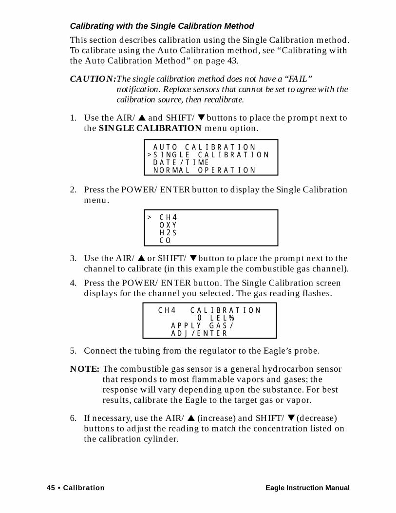
45 • Calibration Eagle Instruction Manual
Calibrating with the Single Calibration Method
This section describes calibration using the Single Calibration method.To calibrate using the Auto Calibration method, see “Calibrating with the Auto Calibration Method” on page 43.
CAUTION:The single calibration method does not have a “FAIL” notification. Replace sensors that cannot be set to agree with the calibration source, then recalibrate.
1. Use the AIR/▲ and SHIFT/▼ buttons to place the prompt next to the SINGLE CALIBRATION menu option.
2. Press the POWER/ENTER button to display the Single Calibration menu.
3. Use the AIR/▲ or SHIFT/▼ button to place the prompt next to the channel to calibrate (in this example the combustible gas channel).
4. Press the POWER/ENTER button. The Single Calibration screen displays for the channel you selected. The gas reading flashes.
5. Connect the tubing from the regulator to the Eagle’s probe.
NOTE: The combustible gas sensor is a general hydrocarbon sensor that responds to most flammable vapors and gases; the response will vary depending upon the substance. For best results, calibrate the Eagle to the target gas or vapor.
6. If necessary, use the AIR/▲ (increase) and SHIFT/▼ (decrease) buttons to adjust the reading to match the concentration listed on the calibration cylinder.
A AC
A RE MI
O L
T
I
IA OE
GU TI NS L
D A T ENN O R M L O P
>/
T
B R A T I O NE C A L I B R A T I O N
C H 4O Y
C OH 2 S
X>
AC
E
L I
RT
C H B R A T I O N0
4E LL %
A P P L Y G A S /A D J / E N
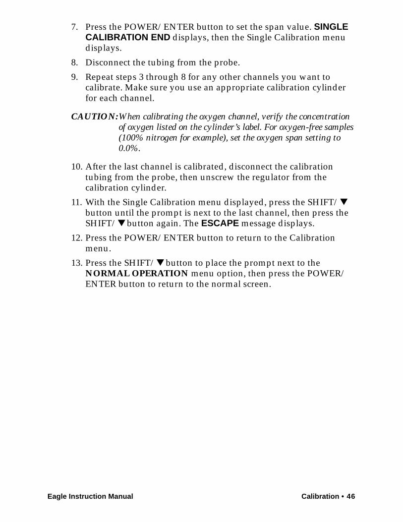
Eagle Instruction Manual Calibration • 46
7. Press the POWER/ENTER button to set the span value. SINGLE CALIBRATION END displays, then the Single Calibration menu displays.
8. Disconnect the tubing from the probe.
9. Repeat steps 3 through 8 for any other channels you want to calibrate. Make sure you use an appropriate calibration cylinder for each channel.
CAUTION:When calibrating the oxygen channel, verify the concentration of oxygen listed on the cylinder’s label. For oxygen-free samples (100% nitrogen for example), set the oxygen span setting to 0.0%.
10. After the last channel is calibrated, disconnect the calibration tubing from the probe, then unscrew the regulator from the calibration cylinder.
11. With the Single Calibration menu displayed, press the SHIFT/▼ button until the prompt is next to the last channel, then press the SHIFT/▼ button again. The ESCAPE message displays.
12. Press the POWER/ENTER button to return to the Calibration menu.
13. Press the SHIFT/▼ button to place the prompt next to the NORMAL OPERATION menu option, then press the POWER/ENTER button to return to the normal screen.
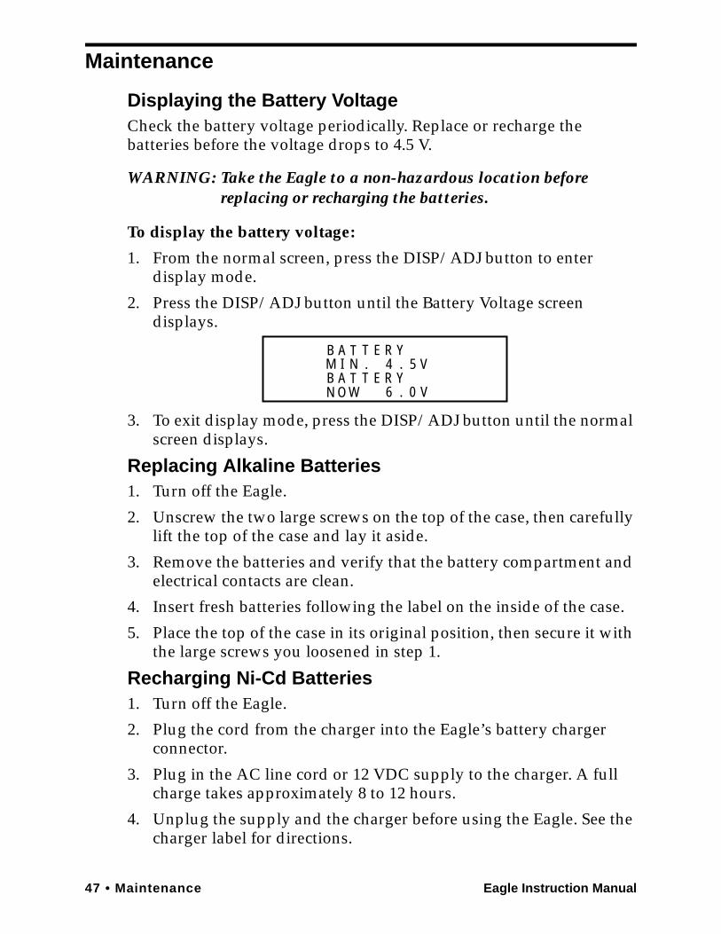
47 • Maintenance Eagle Instruction Manual
Maintenance
Displaying the Battery VoltageCheck the battery voltage periodically. Replace or recharge the batteries before the voltage drops to 4.5 V.
WARNING: Take the Eagle to a non-hazardous location before replacing or recharging the batteries.
To display the battery voltage:
1. From the normal screen, press the DISP/ADJ button to enter display mode.
2. Press the DISP/ADJ button until the Battery Voltage screen displays.
3. To exit display mode, press the DISP/ADJ button until the normal screen displays.
Replacing Alkaline Batteries1. Turn off the Eagle.
2. Unscrew the two large screws on the top of the case, then carefully lift the top of the case and lay it aside.
3. Remove the batteries and verify that the battery compartment and electrical contacts are clean.
4. Insert fresh batteries following the label on the inside of the case.
5. Place the top of the case in its original position, then secure it with the large screws you loosened in step 1.
Recharging Ni-Cd Batteries1. Turn off the Eagle.
2. Plug the cord from the charger into the Eagle’s battery charger connector.
3. Plug in the AC line cord or 12 VDC supply to the charger. A full charge takes approximately 8 to 12 hours.
4. Unplug the supply and the charger before using the Eagle. See the charger label for directions.
B A T T E R YM I N . 4 . 5 VB A T T E R Y
6 0 V.N O W
Eagle Instruction Manual Maintenance • 48
NOTE: Setup mode allows you to select between alkaline and Ni-Cd batteries. The two types of batteries have unique low battery alarm characteristics. To prevent unexpected low battery alarms, always make sure the battery type setting in Setup mode matches the type of batteries installed in the Eagle.
Replacing the Probe’s Particle Filter and Hydrophobic Filter DiskInspect the probe’s internal components if you notice that the Eagle’s pump sounds bogged down or if an unexplained low flow alarm occurs. Replace the particle filter if it appears to be dirty. Replace the hydrophobic filter disk if it appears dirty or saturated with liquid. Replace the O-rings in the probe if either of them appears damaged.
1. Grasp each end of the clear probe body firmly and unscrew the two halves from each other. One half includes a plastic tube fitting and the probe tube. The other half includes a metal fitting that mates with the sample hose or Eagle inlet fitting if it is a standard probe. This half has a plastic fitting if it is a super toxic probe.
Probe BodyProbe Body
Hydrophobic Filter Disk
O-ring (Inside)
O-ring
O-ring (Inside)
Particle Filter
O-ring
HydrophobicFilter Disk
Super Toxic ProbeStandard Probe
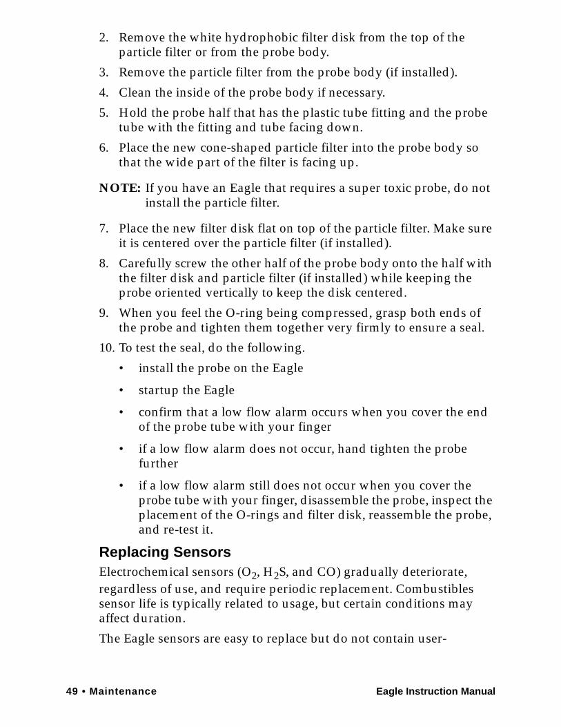
49 • Maintenance Eagle Instruction Manual
2. Remove the white hydrophobic filter disk from the top of the particle filter or from the probe body.
3. Remove the particle filter from the probe body (if installed).
4. Clean the inside of the probe body if necessary.
5. Hold the probe half that has the plastic tube fitting and the probe tube with the fitting and tube facing down.
6. Place the new cone-shaped particle filter into the probe body so that the wide part of the filter is facing up.
NOTE: If you have an Eagle that requires a super toxic probe, do not install the particle filter.
7. Place the new filter disk flat on top of the particle filter. Make sure it is centered over the particle filter (if installed).
8. Carefully screw the other half of the probe body onto the half with the filter disk and particle filter (if installed) while keeping the probe oriented vertically to keep the disk centered.
9. When you feel the O-ring being compressed, grasp both ends of the probe and tighten them together very firmly to ensure a seal.
10. To test the seal, do the following.
• install the probe on the Eagle
• startup the Eagle
• confirm that a low flow alarm occurs when you cover the end of the probe tube with your finger
• if a low flow alarm does not occur, hand tighten the probe further
• if a low flow alarm still does not occur when you cover the probe tube with your finger, disassemble the probe, inspect the placement of the O-rings and filter disk, reassemble the probe, and re-test it.
Replacing SensorsElectrochemical sensors (O2, H2S, and CO) gradually deteriorate, regardless of use, and require periodic replacement. Combustibles sensor life is typically related to usage, but certain conditions may affect duration.
The Eagle sensors are easy to replace but do not contain user-

Eagle Instruction Manual Maintenance • 50
serviceable components. For genuine RKI sensors, call RKI or your local distributor. All sensors are covered by a limited warranty; see warranty for details.
CAUTION:Avoid pulling on sensor wires. Always unplug at the connector.
Replacing the Combustibles Sensor
Replace the combustibles sensor when:
• The combustibles channel cannot be calibrated correctly.
• The LEL reading cannot be set to 0 by the Demand Zero command.
To replace the combustibles sensor:
1. Take the Eagle to a non-hazardous location, and turn the power off.
2. Unscrew the two large screws on the top of the case, then carefully lift the top of the case and lay it aside.
3. Unplug the four-wire connector (red/white/green/black) from the circuit board.
4. Locate the combustibles sensor. With the batteries closest to you, the combustibles sensor is at the top left corner of the sensor block.
5. Remove the two screws in the oval keeper plate, and remove the sensor from the sensor block.
6. Unplug the cable socket from the top of the sensor. Retain the oval keeper plate for use with the replacement sensor.
7. Install the replacement sensor in reverse order.
Replacing the Oxygen Sensor
Replace the oxygen sensor when:
• The O2 channel cannot be set to 00.0% on an oxygen-free sample.
• The O2 display cannot be set to 20.9% by the Demand Zero command.
• The O2 reading drifts noticeably. For example, if the O2 reading varies from 20.5 to 21.5 while you view the display for a few seconds.
To replace the oxygen sensor:
1. Take the Eagle to a non-hazardous location, and turn the power off.
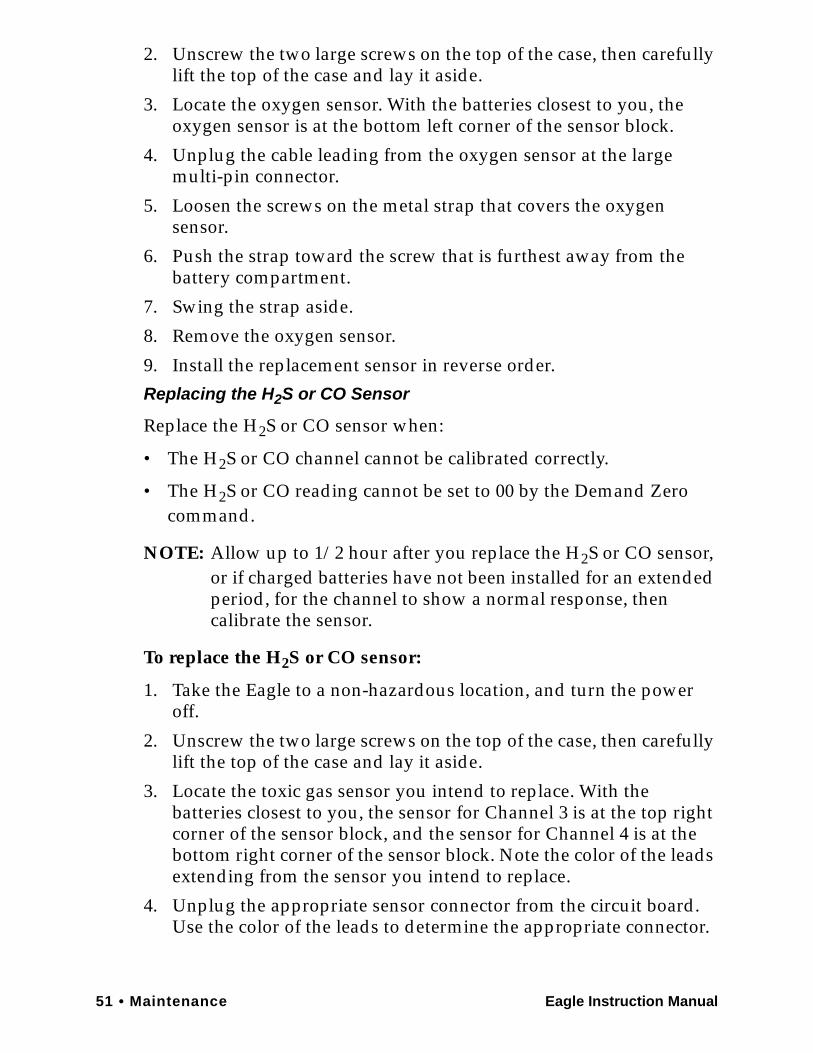
51 • Maintenance Eagle Instruction Manual
2. Unscrew the two large screws on the top of the case, then carefully lift the top of the case and lay it aside.
3. Locate the oxygen sensor. With the batteries closest to you, the oxygen sensor is at the bottom left corner of the sensor block.
4. Unplug the cable leading from the oxygen sensor at the large multi-pin connector.
5. Loosen the screws on the metal strap that covers the oxygen sensor.
6. Push the strap toward the screw that is furthest away from the battery compartment.
7. Swing the strap aside.
8. Remove the oxygen sensor.
9. Install the replacement sensor in reverse order.
Replacing the H2S or CO Sensor
Replace the H2S or CO sensor when:
• The H2S or CO channel cannot be calibrated correctly.
• The H2S or CO reading cannot be set to 00 by the Demand Zero command.
NOTE: Allow up to 1/2 hour after you replace the H2S or CO sensor, or if charged batteries have not been installed for an extended period, for the channel to show a normal response, then calibrate the sensor.
To replace the H2S or CO sensor:
1. Take the Eagle to a non-hazardous location, and turn the power off.
2. Unscrew the two large screws on the top of the case, then carefully lift the top of the case and lay it aside.
3. Locate the toxic gas sensor you intend to replace. With the batteries closest to you, the sensor for Channel 3 is at the top right corner of the sensor block, and the sensor for Channel 4 is at the bottom right corner of the sensor block. Note the color of the leads extending from the sensor you intend to replace.
4. Unplug the appropriate sensor connector from the circuit board. Use the color of the leads to determine the appropriate connector.

Eagle Instruction Manual Maintenance • 52
5. Remove the sensor from the sensor block. If necessary, wiggle the sensor to work it out of the seal.
6. Install the replacement sensor in reverse order.
CAUTION:Verify that you install the H2S or CO sensor in the appropriate flow block position. The Eagle will display inaccurate H2S and CO readings if the sensors are not installed in the correct flow block positions.
The Eagle continues to display H2S and CO readings in the same channels as it did previously regardless of which socket (EC1 or EC2) the sensor is wired to or into which flow block position the sensor is installed. However, the H2S and CO reading will be inaccurate due to the charcoal filter installed before the CO flow block position.
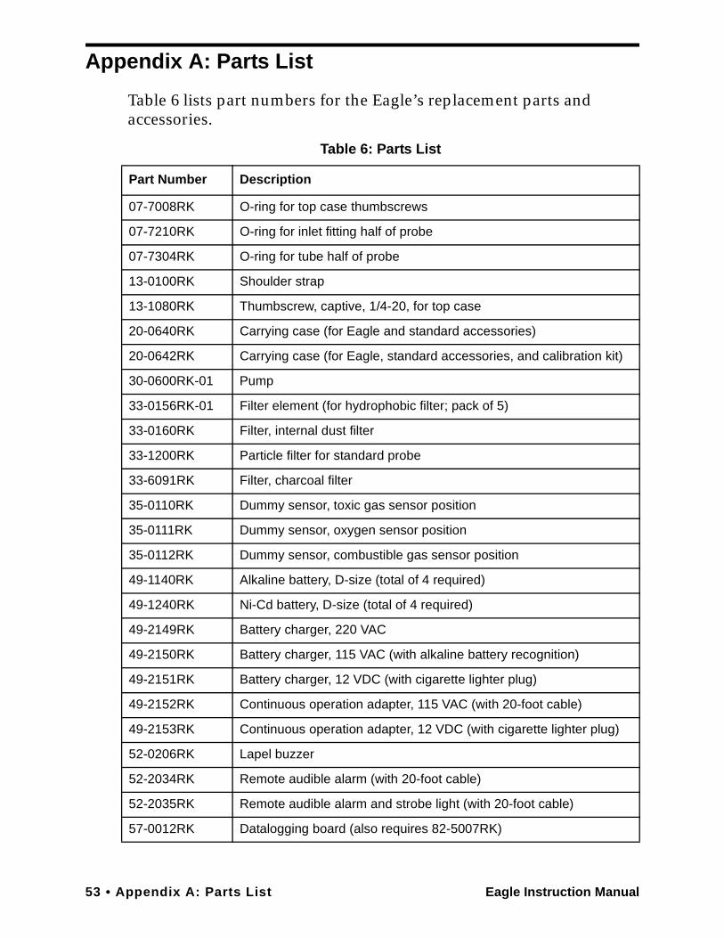
53 • Appendix A: Parts List Eagle Instruction Manual
Appendix A: Parts List
Table 6 lists part numbers for the Eagle’s replacement parts and accessories.
Table 6: Parts List
Part Number Description
07-7008RK O-ring for top case thumbscrews
07-7210RK O-ring for inlet fitting half of probe
07-7304RK O-ring for tube half of probe
13-0100RK Shoulder strap
13-1080RK Thumbscrew, captive, 1/4-20, for top case
20-0640RK Carrying case (for Eagle and standard accessories)
20-0642RK Carrying case (for Eagle, standard accessories, and calibration kit)
30-0600RK-01 Pump
33-0156RK-01 Filter element (for hydrophobic filter; pack of 5)
33-0160RK Filter, internal dust filter
33-1200RK Particle filter for standard probe
33-6091RK Filter, charcoal filter
35-0110RK Dummy sensor, toxic gas sensor position
35-0111RK Dummy sensor, oxygen sensor position
35-0112RK Dummy sensor, combustible gas sensor position
49-1140RK Alkaline battery, D-size (total of 4 required)
49-1240RK Ni-Cd battery, D-size (total of 4 required)
49-2149RK Battery charger, 220 VAC
49-2150RK Battery charger, 115 VAC (with alkaline battery recognition)
49-2151RK Battery charger, 12 VDC (with cigarette lighter plug)
49-2152RK Continuous operation adapter, 115 VAC (with 20-foot cable)
49-2153RK Continuous operation adapter, 12 VDC (with cigarette lighter plug)
52-0206RK Lapel buzzer
52-2034RK Remote audible alarm (with 20-foot cable)
52-2035RK Remote audible alarm and strobe light (with 20-foot cable)
57-0012RK Datalogging board (also requires 82-5007RK)
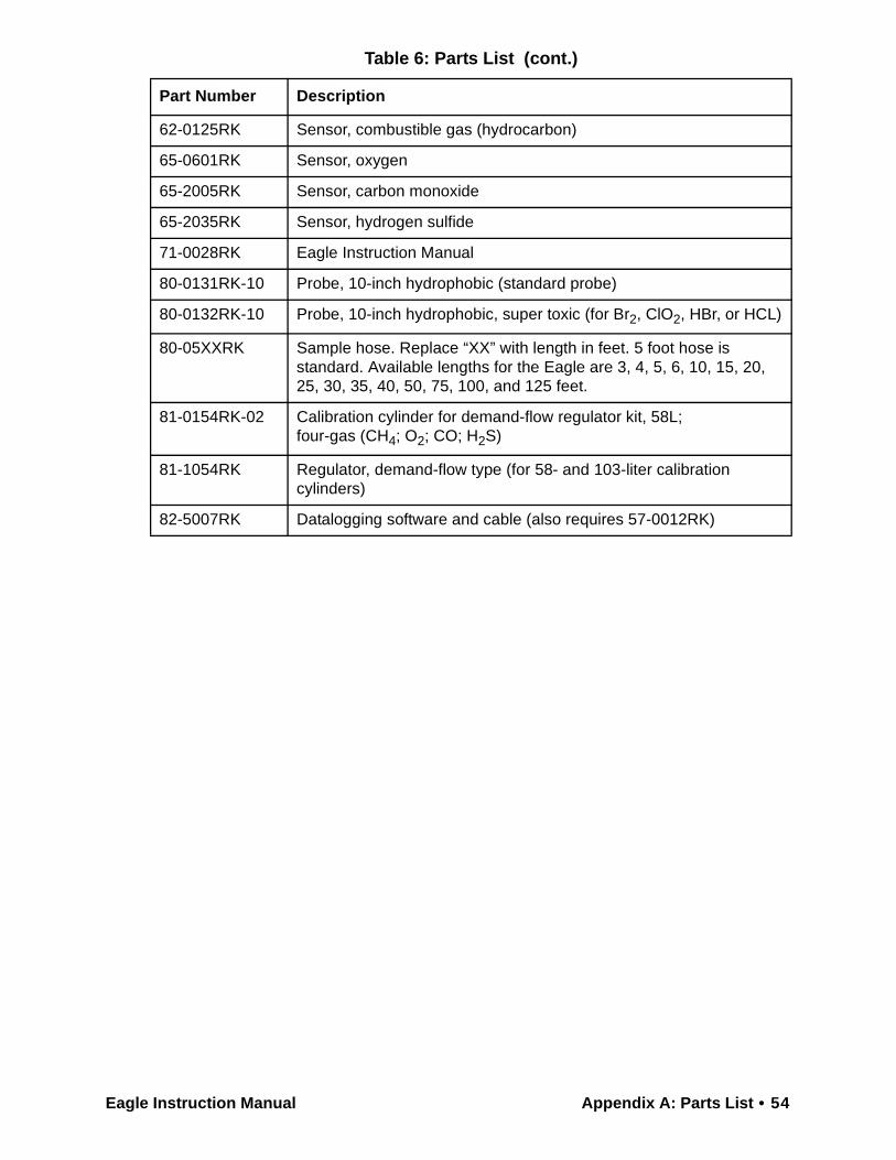
Eagle Instruction Manual Appendix A: Parts List • 54
62-0125RK Sensor, combustible gas (hydrocarbon)
65-0601RK Sensor, oxygen
65-2005RK Sensor, carbon monoxide
65-2035RK Sensor, hydrogen sulfide
71-0028RK Eagle Instruction Manual
80-0131RK-10 Probe, 10-inch hydrophobic (standard probe)
80-0132RK-10 Probe, 10-inch hydrophobic, super toxic (for Br2, ClO2, HBr, or HCL)
80-05XXRK Sample hose. Replace “XX” with length in feet. 5 foot hose is standard. Available lengths for the Eagle are 3, 4, 5, 6, 10, 15, 20, 25, 30, 35, 40, 50, 75, 100, and 125 feet.
81-0154RK-02 Calibration cylinder for demand-flow regulator kit, 58L;four-gas (CH4; O2; CO; H2S)
81-1054RK Regulator, demand-flow type (for 58- and 103-liter calibration cylinders)
82-5007RK Datalogging software and cable (also requires 57-0012RK)
Table 6: Parts List (cont.)
Part Number Description
55 • Appendix B: Methane Elimination Eagle Instruction Manual
Appendix B: Methane Elimination
For applications where methane is an interfering gas, you can set the Eagle to eliminate most response to methane. The methane elimination switch is a standard feature on the circuit board inside the top of the Eagle’s case. An external switch is available as an option. For this type of detection, the combustible gas channel must be programmed to display HEX or *** (see “Updating Channel Settings” on page 26). Eagles with the external methane elimination switch are factory-set with the correct display.
Setting up for Methane Elimination Mode1. Take the Eagle to a fresh-air environment. Set the internal methane
elimination switch to the HEX ON position or the external switch to Methane Response Off.
CAUTION: If the Eagle is equipped with an external methane elimination switch, do not adjust the internal switch. The internal switch should always be in the CH4 position.
2. Allow 2 minutes for the combustibles sensor to stabilize.
3. Perform the demand zero procedure as described in “Preparing for Calibration” on page 42.
WARNING: DO NOT adjust the switch after re-zeroing the Eagle.
Response to CH4 is greatly reduced when the internal switch is set to “HEX ON” or the external switch is set to “Methane Response Off”. If used for methane detection, the internal switch must be set to “CH4” or the external switch set to “Methane Response On”.
Operating with Methane Response OffMonitor for combustible gas as you normally would. When the Eagle is operating in Methane Elimination mode, response to methane is reduced by 90% or more. Response to hexane is reduced slightly (approximately 15%). To convert readings for most common combustible gases, see Table 7 on page 56.
Returning to Methane Response Mode1. Take the Eagle to a fresh-air environment. Set the internal methane
elimination switch to the CH4 position or the external switch to Methane Response On.
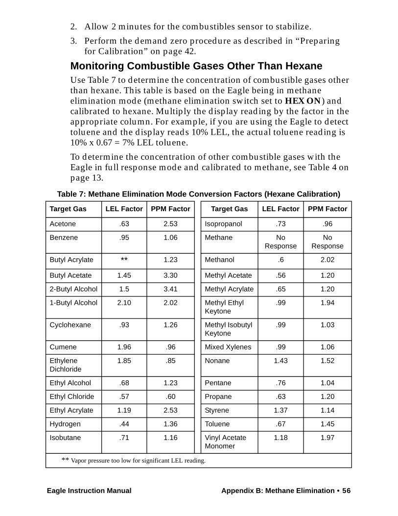
Eagle Instruction Manual Appendix B: Methane Elimination • 56
2. Allow 2 minutes for the combustibles sensor to stabilize.
3. Perform the demand zero procedure as described in “Preparing for Calibration” on page 42.
Monitoring Combustible Gases Other Than HexaneUse Table 7 to determine the concentration of combustible gases other than hexane. This table is based on the Eagle being in methane elimination mode (methane elimination switch set to HEX ON) and calibrated to hexane. Multiply the display reading by the factor in the appropriate column. For example, if you are using the Eagle to detect toluene and the display reads 10% LEL, the actual toluene reading is 10% x 0.67 = 7% LEL toluene.
To determine the concentration of other combustible gases with the Eagle in full response mode and calibrated to methane, see Table 4 on page 13.
Table 7: Methane Elimination Mode Conversion Factors (Hexane Calibration)
Target Gas LEL Factor PPM Factor Target Gas LEL Factor PPM Factor
Acetone .63 2.53 Isopropanol .73 .96
Benzene .95 1.06 Methane No Response
No Response
Butyl Acrylate ** 1.23 Methanol .6 2.02
Butyl Acetate 1.45 3.30 Methyl Acetate .56 1.20
2-Butyl Alcohol 1.5 3.41 Methyl Acrylate .65 1.20
1-Butyl Alcohol 2.10 2.02 Methyl Ethyl Keytone
.99 1.94
Cyclohexane .93 1.26 Methyl Isobutyl Keytone
.99 1.03
Cumene 1.96 .96 Mixed Xylenes .99 1.06
Ethylene Dichloride
1.85 .85 Nonane 1.43 1.52
Ethyl Alcohol .68 1.23 Pentane .76 1.04
Ethyl Chloride .57 .60 Propane .63 1.20
Ethyl Acrylate 1.19 2.53 Styrene 1.37 1.14
Hydrogen .44 1.36 Toluene .67 1.45
Isobutane .71 1.16 Vinyl Acetate Monomer
1.18 1.97
** Vapor pressure too low for significant LEL reading.
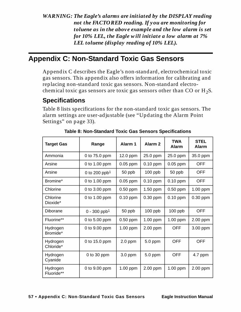
57 • Appendix C: Non-Standard Toxic Gas Sensors Eagle Instruction Manual
WARNING: The Eagle’s alarms are initiated by the DISPLAY reading not the FACTORED reading. If you are monitoring for toluene as in the above example and the low alarm is set for 10% LEL, the Eagle will initiate a low alarm at 7% LEL toluene (display reading of 10% LEL).
Appendix C: Non-Standard Toxic Gas Sensors
Appendix C describes the Eagle’s non-standard, electrochemical toxic gas sensors. This appendix also offers information for calibrating and replacing non-standard toxic gas sensors. Non-standard electro-chemical toxic gas sensors are toxic gas sensors other than CO or H2S.
SpecificationsTable 8 lists specifications for the non-standard toxic gas sensors. The alarm settings are user-adjustable (see “Updating the Alarm Point Settings” on page 33).
Table 8: Non-Standard Toxic Gas Sensors Specifications
Target Gas Range Alarm 1 Alarm 2 TWA Alarm
STEL Alarm
Ammonia 0 to 75.0 ppm 12.0 ppm 25.0 ppm 25.0 ppm 35.0 ppm
Arsine 0 to 1.00 ppm 0.05 ppm 0.10 ppm 0.05 ppm OFF
Arsine 0 to 200 ppb1 50 ppb 100 ppb 50 ppb OFF
Bromine* 0 to 1.00 ppm 0.05 ppm 0.10 ppm 0.10 ppm OFF
Chlorine 0 to 3.00 ppm 0.50 ppm 1.50 ppm 0.50 ppm 1.00 ppm
Chlorine Dioxide*
0 to 1.00 ppm 0.10 ppm 0.30 ppm 0.10 ppm 0.30 ppm
Diborane 0 - 300 ppb1 50 ppb 100 ppb 100 ppb OFF
Fluorine** 0 to 5.00 ppm 0.50 ppm 1.00 ppm 1.00 ppm 2.00 ppm
Hydrogen Bromide*
0 to 9.00 ppm 1.00 ppm 2.00 ppm OFF 3.00 ppm
Hydrogen Chloride*
0 to 15.0 ppm 2.0 ppm 5.0 ppm OFF OFF
Hydrogen Cyanide
0 to 30 ppm 3.0 ppm 5.0 ppm OFF 4.7 ppm
Hydrogen Fluoride**
0 to 9.00 ppm 1.00 ppm 2.00 ppm 1.00 ppm 2.00 ppm
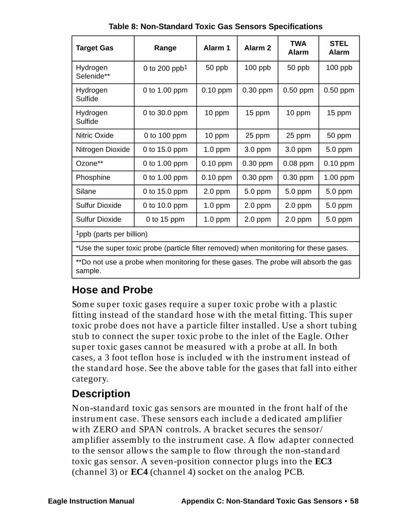
Eagle Instruction Manual Appendix C: Non-Standard Toxic Gas Sensors • 58
Hose and ProbeSome super toxic gases require a super toxic probe with a plastic fitting instead of the standard hose with the metal fitting. This super toxic probe does not have a particle filter installed. Use a short tubing stub to connect the super toxic probe to the inlet of the Eagle. Other super toxic gases cannot be measured with a probe at all. In both cases, a 3 foot teflon hose is included with the instrument instead of the standard hose. See the above table for the gases that fall into either category.
DescriptionNon-standard toxic gas sensors are mounted in the front half of the instrument case. These sensors each include a dedicated amplifier with ZERO and SPAN controls. A bracket secures the sensor/amplifier assembly to the instrument case. A flow adapter connected to the sensor allows the sample to flow through the non-standard toxic gas sensor. A seven-position connector plugs into the EC3 (channel 3) or EC4 (channel 4) socket on the analog PCB.
Hydrogen Selenide**
0 to 200 ppb1 50 ppb 100 ppb 50 ppb 100 ppb
Hydrogen Sulfide
0 to 1.00 ppm 0.10 ppm 0.30 ppm 0.50 ppm 0.50 ppm
Hydrogen Sulfide
0 to 30.0 ppm 10 ppm 15 ppm 10 ppm 15 ppm
Nitric Oxide 0 to 100 ppm 10 ppm 25 ppm 25 ppm 50 ppm
Nitrogen Dioxide 0 to 15.0 ppm 1.0 ppm 3.0 ppm 3.0 ppm 5.0 ppm
Ozone** 0 to 1.00 ppm 0.10 ppm 0.30 ppm 0.08 ppm 0.10 ppm
Phosphine 0 to 1.00 ppm 0.10 ppm 0.30 ppm 0.30 ppm 1.00 ppm
Silane 0 to 15.0 ppm 2.0 ppm 5.0 ppm 5.0 ppm 5.0 ppm
Sulfur Dioxide 0 to 10.0 ppm 1.0 ppm 2.0 ppm 2.0 ppm 5.0 ppm
Sulfur Dioxide 0 to 15 ppm 1.0 ppm 2.0 ppm 2.0 ppm 5.0 ppm
1ppb (parts per billion)
*Use the super toxic probe (particle filter removed) when monitoring for these gases.
**Do not use a probe when monitoring for these gases. The probe will absorb the gas sample.
Table 8: Non-Standard Toxic Gas Sensors Specifications
Target Gas Range Alarm 1 Alarm 2 TWA Alarm
STEL Alarm
59 • Appendix C: Non-Standard Toxic Gas Sensors Eagle Instruction Manual
CAUTION:Some Eagles equipped with non-standard toxic gas sensors include a special plastic inlet fitting that requires a Teflon sample hose. The standard hose with metal fittings cannot be used with these Eagles. Using a standard sample hose for these applications will result in inaccurate gas readings for the toxic gases. Gases that require the plastic inlet fitting and Teflon sample hose include ozone, hydrogen fluoride, hydrogen chloride, and chlorine dioxide.
Keeping Fresh Batteries in a Non-Standard Toxic EagleThe non-standard toxic sensors require a bias voltage to be applied to them at all times, even when the Eagle is turned off, to maintain proper operation. This bias voltage is maintained even when the Eagle is turned off as long as the batteries in the Eagle have enough voltage to operate the Eagle (4.5 volts or greater). Once the batteries are drained to the point that they will not operate the Eagle, they will no longer provide a reliable bias voltage to the non-standard toxic sensors. When the Eagle indicates a dead battery alarm, change the batteries as soon as possible to maintain the bias voltage.
If the Eagle is stored for an extended period, check the battery voltage periodically by turning on the Eagle and scrolling through Display Mode to the Battery Voltage screen. If the battery voltage is close to being considered dead, 4.5 volts, replace the batteries. A set of batteries with full capacity will maintain a bias voltage on non-standard toxic sensors in a stored Eagle for at least 3 months. RKI Instruments Inc. recommends that you check the battery voltage on a stored Eagle that includes non-standard toxic sensors monthly to insure that the batteries are not dead.
WARNING: If the non-standard toxic sensors are allowed to be without a bias voltage for an extended period, they will deteriorate and no longer operate properly. Be sure to keep fresh batteries in the Eagle when it is not being used or if it is stored.
Calibrating Non-Standard Toxic Gas SensorsRecommended calibration frequency for non-standard toxics sensors is 3 to 6 months. Use the Single Calibration method to calibrate non-standard toxic gas sensors as described in the Calibration section of this manual with the following exception.
1. At the Single Calibration screen, press the SHIFT/▼ button to
Eagle Instruction Manual Appendix C: Non-Standard Toxic Gas Sensors • 60
scroll down to the appropriate gas, then press thePOWER/ENTER button.
2. Screw the regulator to the appropriate calibration cylinder.
3. Connect the tubing from the regulator to the Eagle’s probe. Allow 2 minutes for the reading to stabilize.
4. If necessary, use the AIR/▲ (increase) and SHIFT/▼ (decrease) buttons to adjust the reading to match the concentration listed on the calibration cylinder.
Go to the next section, “Adjusting the sensor potentiometers,” if you are unable to match the reading to the concentration of the cylinder.
5. Press the POWER/ENTER button to set the span value. SINGLE CALIBRATION END displays, then the Single Calibration menu displays.
6. Disconnect the tubing from the probe.7. Unscrew the regulator from the calibration cylinder.8. With the Single Calibration menu displayed, press the SHIFT/▼
button until the prompt is next to the last channel, then press the SHIFT/▼ button again. The ESCAPE message displays.
9. Press the POWER/ENTER button to return to the Calibration menu.
10. Press the SHIFT/▼ button to place the prompt next to the NORMAL OPERATION menu option, then press the POWER/ENTER button to return to the normal screen.
Adjusting the Sensor Controls
CAUTION:Only perform the following steps if you are unable to set the correct calibration reading with the AIR/▲ and SHIFT/▼ buttons.
1. Use the AIR/▲ and SHIFT/▼ buttons to set the reading to the middle of the range in which you can currently adjust the reading. For example, if you can set the reading from a minimum of 1.0 ppm to a maximum of 3.0 ppm, set the display to 2.0 ppm.
2. Unscrew the two large screws on the top of the case, then carefully lift the top of the case and lay it aside.
3. Locate the sensor in the front half of the bottom case. The sensor with wires connected to EC3 on the analog PCB displays its
61 • Appendix C: Non-Standard Toxic Gas Sensors Eagle Instruction Manual
reading on the third line of the screen. The sensor connected to EC4 on the analog PCB displays its reading on the fourth line of the screen.
4. Adjust the sensor’s SPAN control one turn and observe the display reading. Continue to adjust the SPAN control until the display reading matches the concentration of the calibration cylinder.The SPAN control is located next to the sensor on the side closest to the front of the instrument.
5. Press the POWER/ENTER button to set the span value. SINGLE CALIBRATION END displays, then the Single Calibration menu displays.
6. Place the top of the case in its original position, then secure it with the large screws you loosened in step 2.
7. Disconnect the tubing from the probe, then unscrew the regulator from the calibration cylinder.
8. With the Single Calibration menu displayed, press the SHIFT/▼ button until the prompt is next to the last channel, then press the SHIFT/▼ button again. The ESCAPE message displays.
9. Press the POWER/ENTER button to return to the Calibration menu.
10. Press the SHIFT/▼ button to place the prompt next to the NORMAL OPERATION menu option, then press the POWER/ENTER button to return to the normal screen.
NOTE: If a non-standard toxics channel displays Zero Fail after the Demand Zero procedure, adjust the ZERO control (next to SPAN) until the reading displays the smallest increment above 0.0. For example, 0.01 or 0.1. Repeat Demand Zero.
Replacing Non-Standard Toxic Gas SensorsReplace the non-standard toxic gas sensor when:
• The toxic gas channel cannot be calibrated correctly.
• The toxic gas reading cannot be set to zero by the Demand Zero command or zero potentiometer.
NOTE: RKI Instruments, Inc. recommends that you return the Eagle for replacement of the non-standard toxic gas sensor. The following procedure is provided to allow you to replace the sensor if necessary.
Eagle Instruction Manual Appendix C: Non-Standard Toxic Gas Sensors • 62
1. Take the Eagle to a non-hazardous location, and turn the power off.
2. Unscrew the two large screws on the top of the case, then carefully lift the top of the case and lay it aside.
3. In the front half of the bottom case, locate the sensor you want to replace. The sensor with wires connected to EC3 on the analog PCB displays its reading on the third line of the screen. The sensor connected to EC4 on the analog PCB displays its reading on the fourth line of the screen.
4. Remove the two screws at the base of the bracket.
5. Lift the sensor assembly up enough to remove the flow adapter(two screws). The flow adapter is attached to the sensor.
CAUTION:Avoid pulling on sensor wires. Always unplug at the connector.
6. Disconnect the connector from the analog PCB. Note to which socket (EC3 or EC4) the connector is connected.
7. Remove the sensor assembly from the instrument case.
8. Remove the two screws that secure the sensor assembly to the bracket.
9. Remove the two screws that secure the sensor to the amplifier, then remove the sensor from the amplifier. Retain the amplifier for use with the replacement sensor.
10. Install the replacement sensor in reverse order.
NOTE: Allow up to 4 hours after you replace a non-standard toxic gas sensor, or if charged batteries have not been installed for an extended period, for the channel to show a normal response, then calibrate the sensor.
Parts ListTable 9 lists part numbers for replacement parts and accessories of the Eagle’s non-standard toxic gas sensors.
Table 9: Parts List: Non-Standard Toxic Gas Sensors
Part Number Description
06-1273RK Tubing, 1/4 in. x 1/8 in. PTFE (order by foot; 3 ft. standard;consult RKI Instruments, Inc., for lengths longer than 3 ft.)
81-0149RK-02 Calibration cylinder, 58-liter (5 ppm H2S in nitrogen)
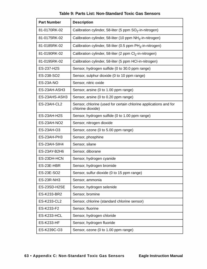
63 • Appendix C: Non-Standard Toxic Gas Sensors Eagle Instruction Manual
81-0170RK-02 Calibration cylinder, 58-liter (5 ppm SO2-in-nitrogen)
81-0175RK-02 Calibration cylinder, 58-liter (10 ppm NH3-in-nitrogen)
81-0185RK-02 Calibration cylinder, 58-liter (0.5 ppm PH3-in-nitrogen)
81-0190RK-02 Calibration cylinder, 58-liter (2 ppm Cl2-in-nitrogen)
81-0195RK-02 Calibration cylinder, 58-liter (5 ppm HCl-in-nitrogen)
ES-237-H2S Sensor, hydrogen sulfide (0 to 30.0 ppm range)
ES-238-SO2 Sensor, sulphur dioxide (0 to 10 ppm range)
ES-23A-NO Sensor, nitric oxide
ES-23AH-ASH3 Sensor, arsine (0 to 1.00 ppm range)
ES-23AHS-ASH3 Sensor, arsine (0 to 0.20 ppm range)
ES-23AH-CL2 Sensor, chlorine (used for certain chlorine applications and for chlorine dioxide)
ES-23AH-H2S Sensor, hydrogen sulfide (0 to 1.00 ppm range)
ES-23AH-NO2 Sensor, nitrogen dioxide
ES-23AH-O3 Sensor, ozone (0 to 5.00 ppm range)
ES-23AH-PH3 Sensor, phosphine
ES-23AH-SIH4 Sensor, silane
ES-23AY-B2H6 Sensor, diborane
ES-23DH-HCN Sensor, hydrogen cyanide
ES-23E-HBR Sensor, hydrogen bromide
ES-23E-SO2 Sensor, sulfur dioxide (0 to 15 ppm range)
ES-23R-NH3 Sensor, ammonia
ES-23SD-H2SE Sensor, hydrogen selenide
ES-K233-BR2 Sensor, bromine
ES-K233-CL2 Sensor, chlorine (standard chlorine sensor)
ES-K233-F2 Sensor, fluorine
ES-K233-HCL Sensor, hydrogen chloride
ES-K233-HF Sensor, hydrogen fluoride
ES-K239C-O3 Sensor, ozone (0 to 1.00 ppm range)
Table 9: Parts List: Non-Standard Toxic Gas Sensors
Part Number Description
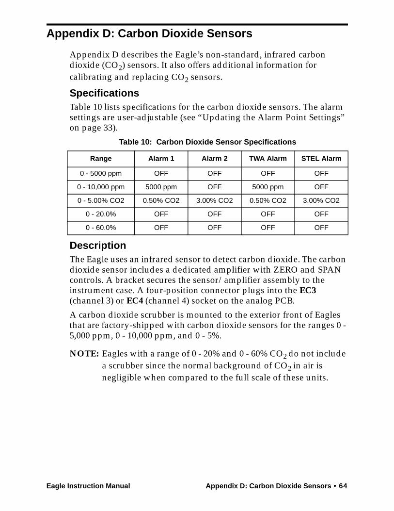
Eagle Instruction Manual Appendix D: Carbon Dioxide Sensors • 64
Appendix D: Carbon Dioxide Sensors
Appendix D describes the Eagle’s non-standard, infrared carbon dioxide (CO2) sensors. It also offers additional information for calibrating and replacing CO2 sensors.
SpecificationsTable 10 lists specifications for the carbon dioxide sensors. The alarm settings are user-adjustable (see “Updating the Alarm Point Settings” on page 33).
DescriptionThe Eagle uses an infrared sensor to detect carbon dioxide. The carbon dioxide sensor includes a dedicated amplifier with ZERO and SPAN controls. A bracket secures the sensor/amplifier assembly to the instrument case. A four-position connector plugs into the EC3 (channel 3) or EC4 (channel 4) socket on the analog PCB.
A carbon dioxide scrubber is mounted to the exterior front of Eagles that are factory-shipped with carbon dioxide sensors for the ranges 0 - 5,000 ppm, 0 - 10,000 ppm, and 0 - 5%.
NOTE: Eagles with a range of 0 - 20% and 0 - 60% CO2 do not include a scrubber since the normal background of CO2 in air is negligible when compared to the full scale of these units.
Table 10: Carbon Dioxide Sensor Specifications
Range Alarm 1 Alarm 2 TWA Alarm STEL Alarm
0 - 5000 ppm OFF OFF OFF OFF
0 - 10,000 ppm 5000 ppm OFF 5000 ppm OFF
0 - 5.00% CO2 0.50% CO2 3.00% CO2 0.50% CO2 3.00% CO2
0 - 20.0% OFF OFF OFF OFF
0 - 60.0% OFF OFF OFF OFF

65 • Appendix D: Carbon Dioxide Sensors Eagle Instruction Manual
This scrubber is for use when setting the carbon dioxide sensor’s zero reading only. Two black vinyl caps cover either end of the carbon dioxide scrubber. To prolong the life of the scrubber, be sure the caps are installed while the scrubber is not in use or while it is being stored. Replace the scrubber when it turns from white to a violet color.
CAUTION: Do not connect the probe to the scrubber during normal operation or when setting the span reading during calibration.
Normal Operation of Carbon Dioxide SensorsCarbon dioxide is a background gas in fresh air. Table 11 indicates typical gas readings for each of the Eagle’s carbon dioxide sensors.
Demand Zero for Carbon Dioxide SensorsWhen setting the zero reading, the carbon dioxide scrubber mounted to the front of the Eagle allows you to eliminate carbon dioxide normally found in fresh air.
NOTE: When performing a demand zero with a 0 - 20% or 0 - 60% CO2 unit, the use of a scrubber is not required.
1. Remove the black caps from the ends of the carbon dioxide scrubber. Be sure to grab the scrubber by the Eagle fitting so that the fitting and tubing do not come off.
2. Connect the carbon dioxide scrubber directly to the Eagle’s inlet fitting.
3. Wait one minute for the fresh air sample to flow through the
Table 11: Carbon Dioxide Fresh Air Readings
Range ApproximateFresh Air Reading
0 - 5000 ppm 400 ppm
0 - 10,000 ppm 400 ppm
0 - 5.00% 0.04%
0 - 20.0 & 0 - 60.0% 0.0%
End Caps
Eagle Instruction Manual Appendix D: Carbon Dioxide Sensors • 66
carbon dioxide scrubber, then press the AIR/▲ button to set the zero reading.
If the carbon dioxide sensor fails when you press the AIR/▲ button, use the zero control (marked F. ZERO) on the amplifier to adjust the reading to zero.
CAUTION:Do not adjust the coarse zero potentiometer (marked C.ZERO).
4. Remove the tubing from the carbon dioxide scrubber and probe.
5. Put the caps back on the scrubber.
Calibrating Carbon Dioxide SensorsRecommended calibration frequency for carbon dioxide sensors is once every 3 months. Enter Calibration mode and calibrate carbon dioxide sensors as described in the Calibration section of this manual. Use the Auto Calibration method if a calibration cylinder is available that includes all target gases for your Eagle. Use the Single Calibration method if you are using a carbon dioxide calibration cylinder.
NOTE: If you are using the Auto Calibration method, go to the Calibration Values screen, verify that the carbon dioxide value matches the concentration of carbon dioxide in the four-gas calibration cylinder, then proceed with step 2.
1. At the Single Calibration screen, press the SHIFT/▼ button to scroll down to the carbon dioxide channel, then press the POWER/ENTER button.
2. Screw the regulator to the appropriate calibration cylinder.
3. Connect the tubing from the regulator to the Eagle’s probe. Allow 1 minute for the reading to stabilize.
4. If necessary, use the AIR/▲ (increase) and SHIFT/▼ (decrease) buttons to adjust the carbon dioxide reading to match the concentration listed on the calibration cylinder.
Go to the next section, “Adjusting the sensor potentiometers,” if you are unable to match the reading to the concentration of the calibration cylinder.
5. Press the POWER/ENTER button to set the span value. SINGLE CALIBRATION END displays, then the Single Calibration menu displays.
6. Disconnect the tubing from the probe, then unscrew the regulator from the cylinder.

67 • Appendix D: Carbon Dioxide Sensors Eagle Instruction Manual
7. With the Single Calibration menu displayed, press the SHIFT/▼ button until the prompt is next to the last channel, then press the SHIFT/▼ button again. The ESCAPE message displays.
8. Press the POWER/ENTER button to return to the Calibration menu.
9. Press the SHIFT/▼ button to place the prompt next to the NORMAL OPERATION menu option, then press the POWER/ENTER button to return to the normal screen.
Adjusting the Sensor Controls
CAUTION:Only perform the following steps if you are unable to set the correct calibration reading with the AIR/▲ and SHIFT/▼ buttons.
1. Use the AIR/▲ and SHIFT/▼ buttons to set the reading to the middle of the range in which you can currently adjust the reading. For example, if you can set the reading from a minimum of 1.00% CO2 to a maximum of 3.00% CO2, set the display to 2.00% CO2.
2. Unscrew the two large screws on the top of the case, then carefully lift the top of the case and lay it aside.
3. Locate the carbon dioxide sensor in the front half of the bottom case. A sensor with wires connected to EC3 on the analog PCB displays its reading on the third line of the screen. A sensor connected to EC4 on the analog PCB displays its reading on the fourth line of the screen.
4. Adjust the carbon dioxide sensor’s SPAN control one turn and observe the display reading. Continue to adjust the SPAN control until the display reading matches the concentration of the calibration cylinder.
The SPAN control is located on the top edge of the amplifier and is the control closest to the front of the instrument. (The front of the instrument has the scrubber attached to it.)
5. Press the POWER/ENTER button to set the span value. SINGLE CALIBRATION END displays, then the Single Calibration menu displays.
6. Place the top of the case in its original position, then secure it with the large screws you loosened in step 5.
7. Disconnect the tubing from the probe.
8. Unscrew the regulator from the calibration cylinder.

Eagle Instruction Manual Appendix D: Carbon Dioxide Sensors • 68
9. With the Single Calibration menu displayed, press the SHIFT/▼ button until the prompt is next to the last channel, then press the SHIFT/▼ button again. The ESCAPE message displays.
10. Press the POWER/ENTER button to return to the Calibration menu.
11. Press the SHIFT/▼ button to place the prompt next to the NORMAL OPERATION menu option, then press thePOWER/ENTER button to return to the normal screen.
Replacing Carbon Dioxide SensorsReturn the Eagle to RKI Instruments, Inc. for replacement of the carbon dioxide sensor when:
• The carbon dioxide channel cannot be calibrated correctly.
• The carbon dioxide reading cannot be set to zero by the Demand Zero command or zero potentiometer.
Parts ListTable 12 lists part numbers for replacement parts and accessories of the Eagle’s carbon dioxide sensors.
Table 12: Parts List: Carbon Dioxide Sensors
Part Number Description
33-6010RK-01 Scrubber, carbon dioxide
81-0070RK-03 Calibration cylinder, 103-liter (2000 ppm CO2)
81-0071RK-03 Calibration cylinder, 103-liter (5000 ppm CO2)
81-0072RK-03 Calibration cylinder, 103-liter (2.5% CO2)
81-0073RK-03 Calibration cylinder, 103-liter (15% CO2)
81-1054RK Regulator, demand-flow type (for 58- and 103-liter calibration cylinders)
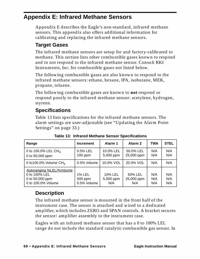
69 • Appendix E: Infrared Methane Sensors Eagle Instruction Manual
Appendix E: Infrared Methane Sensors
Appendix E describes the Eagle’s non-standard, infrared methane sensors. This appendix also offers additional information for calibrating and replacing the infrared methane sensors.
Target GasesThe infrared methane sensors are setup for and factory-calibrated to methane. This section lists other combustible gases known to respond and to not respond to the infrared methane sensor. Consult RKI Instruments, Inc. for combustible gases not listed below.
The following combustible gases are also known to respond to the infrared methane sensors: ethane, hexane, IPA, isobutane, MEK, propane, toluene.
The following combustible gases are known to not respond or respond poorly to the infrared methane sensor: acetylene, hydrogen, styrene.
SpecificationsTable 13 lists specifications for the infrared methane sensors. The alarm settings are user-adjustable (see “Updating the Alarm Point Settings” on page 33.)
DescriptionThe infrared methane sensor is mounted in the front half of the instrument case. The sensor is attached and wired to a dedicated amplifier, which includes ZERO and SPAN controls. A bracket secures the sensor/amplifier assembly to the instrument case.
Eagles with an infrared methane sensor that has a 0 to 100% LEL range do not include the standard catalytic combustible gas sensor. In
Table 13: Infrared Methane Sensor Specifications
Range Increment Alarm 1 Alarm 2 TWA STEL
0 to 100.0% LEL CH40 to 50,000 ppm
0.5% LEL100 ppm
10.0% LEL5,000 ppm
50.0% LEL25,000 ppm
N/AN/A
N/AN/A
0 to100.0% Volume CH4 0.5% Volume 10.0% VOL 20.0% VOL N/A N/A
Autoranging %LEL/%Volume0 to 100% LEL0 to 50,000 ppm0 to 100.0% Volume
1% LEL500 ppm0.5% Volume
10% LEL5,000 ppm
N/A
50% LEL25,000 ppm
N/A
N/AN/AN/A
N/AN/AN/A
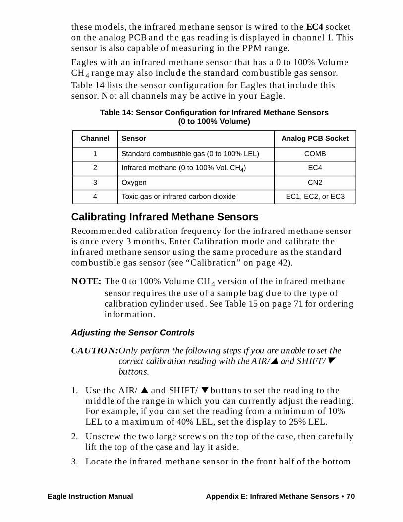
Eagle Instruction Manual Appendix E: Infrared Methane Sensors • 70
these models, the infrared methane sensor is wired to the EC4 socket on the analog PCB and the gas reading is displayed in channel 1. This sensor is also capable of measuring in the PPM range.
Eagles with an infrared methane sensor that has a 0 to 100% Volume CH4 range may also include the standard combustible gas sensor. Table 14 lists the sensor configuration for Eagles that include this sensor. Not all channels may be active in your Eagle.
Calibrating Infrared Methane SensorsRecommended calibration frequency for the infrared methane sensor is once every 3 months. Enter Calibration mode and calibrate the infrared methane sensor using the same procedure as the standard combustible gas sensor (see “Calibration” on page 42).
NOTE: The 0 to 100% Volume CH4 version of the infrared methane sensor requires the use of a sample bag due to the type of calibration cylinder used. See Table 15 on page 71 for ordering information.
Adjusting the Sensor Controls
CAUTION:Only perform the following steps if you are unable to set the correct calibration reading with the AIR/▲ and SHIFT/▼ buttons.
1. Use the AIR/▲ and SHIFT/▼ buttons to set the reading to the middle of the range in which you can currently adjust the reading. For example, if you can set the reading from a minimum of 10% LEL to a maximum of 40% LEL, set the display to 25% LEL.
2. Unscrew the two large screws on the top of the case, then carefully lift the top of the case and lay it aside.
3. Locate the infrared methane sensor in the front half of the bottom
Table 14: Sensor Configuration for Infrared Methane Sensors(0 to 100% Volume)
Channel Sensor Analog PCB Socket
1 Standard combustible gas (0 to 100% LEL) COMB
2 Infrared methane (0 to 100% Vol. CH4) EC4
3 Oxygen CN2
4 Toxic gas or infrared carbon dioxide EC1, EC2, or EC3
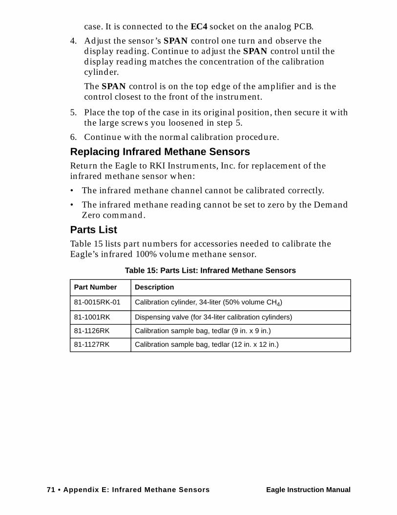
71 • Appendix E: Infrared Methane Sensors Eagle Instruction Manual
case. It is connected to the EC4 socket on the analog PCB.
4. Adjust the sensor’s SPAN control one turn and observe the display reading. Continue to adjust the SPAN control until the display reading matches the concentration of the calibration cylinder.
The SPAN control is on the top edge of the amplifier and is the control closest to the front of the instrument.
5. Place the top of the case in its original position, then secure it with the large screws you loosened in step 5.
6. Continue with the normal calibration procedure.
Replacing Infrared Methane SensorsReturn the Eagle to RKI Instruments, Inc. for replacement of the infrared methane sensor when:
• The infrared methane channel cannot be calibrated correctly.
• The infrared methane reading cannot be set to zero by the Demand Zero command.
Parts ListTable 15 lists part numbers for accessories needed to calibrate the Eagle’s infrared 100% volume methane sensor.
Table 15: Parts List: Infrared Methane Sensors
Part Number Description
81-0015RK-01 Calibration cylinder, 34-liter (50% volume CH4)
81-1001RK Dispensing valve (for 34-liter calibration cylinders)
81-1126RK Calibration sample bag, tedlar (9 in. x 9 in.)
81-1127RK Calibration sample bag, tedlar (12 in. x 12 in.)
Eagle Instruction Manual Appendix F: Eagle Tank Tester Model • 72
Appendix F: Eagle Tank Tester Model
The Eagle Tank Tester model is intended for checking tanks or vessels that may contain residual hydrocarbon vapors or water or may have been purged of oxygen. You can also use this model as a standard Eagle gas monitor by connecting the standard hose and probe and updating the oxygen alarms to the default settings.
DescriptionThe tank tester model has an additional socket on the front on the housing to accommodate connection of the float probe assembly. This model includes the following non-standard components.
Float Probe Assembly
The float probe assembly helps prevent liquid from being drawn into the Eagle. The float probe assembly is 12-feet long. A quick disconnect fitting at one end of the assembly connects to the Eagle’s inlet fitting. The same end of the probe also includes a short wire that terminates in a jack. This jack connects to the float probe socket that is adjacent to the Eagle’s inlet fitting. The float probe switch at the opposite end of the 12-foot cable shuts off the pump if the probe begins to be submerged into a liquid.
To use the float probe assembly:
CAUTION:Drawing water, gasoline, or other liquids into the Eagle will cause damage.
1. Attach the quick disconnect fitting to the Eagle’s standard inlet fitting.
2. Attach the jack to the socket that is adjacent to the inlet fitting.
3. Lower the probe into the tank or vessel. Lower the probe very slowly to allow the float switch to activate if necessary.
Dilution Fitting (1:1)
CAUTION:When measuring oxygen readings, remove the dilution fitting or use your finger to seal the small dilution hole on the side of the dilution fitting.
The standard combustible gas sensor requires oxygen to operate. In environments where there is not enough oxygen to operate the combustible gas sensor, (for example a tank purged with an inerting gas), the 1:1 dilution fitting adds sufficient oxygen by blending
73 • Appendix F: Eagle Tank Tester Model Eagle Instruction Manual
ambient air with the incoming sample. The standard dilution fitting dilutes at a ratio of 1:1 (one part air to one part sample).
To attach the dilution fitting:
1. Attach the dilution fitting’s quick disconnect fitting to the Eagle’s inlet fitting.
2. Attach the hose to the opposite end of the dilution fitting.
NOTE: When using the dilution fitting, multiply the combustible gas reading (LEL or PPM) by 2 to determine the actual combustible gas concentration. Always remove the dilution fitting or seal the dilution hole to measure for oxygen.
AlarmsThe Eagle Tank Tester model has two alarms for oxygen. They are factory-set at 5.0% by volume (increasing) and 19.5% by volume (decreasing).
The increasing alarm is used to monitor a purged vessel to alert you to a rising oxygen condition. The decreasing alarm is generally used for confined space entry to warn you of dangerously low breathing levels.
ANY oxygen level is either above or below one of these alarm levels, so the Eagle Tank Tester version will go into alarm when first turned on. To silence the alarm, press the RESET button. The audible alarm silences, but the alarm lights continue to flash and the display screen continues to indicate an oxygen alarm. If one of the alarm levels is newly exceeded, the audible alarm sounds again.
To eliminate an oxygen alarm that is not being used:
Either the increasing or decreasing oxygen alarm can be turned off in Setup mode (see “Updating the Alarm Point Settings” on page 33). Turning off the alarm clears the alarm lights and display of an unnecessary alarm.
CalibrationUse a hexane calibrating source to calibrate the combustible gas LEL range. Use a 100% nitrogen calibrating source to set the zero reading for the oxygen channel. RKI Instruments, Inc. recommends using the Single Calibration method to calibrate the Eagle Tank Tester model. See “Calibration” on page 42.
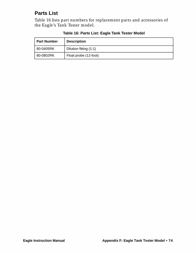
Eagle Instruction Manual Appendix F: Eagle Tank Tester Model • 74
Parts ListTable 16 lists part numbers for replacement parts and accessories of the Eagle’s Tank Tester model.
Table 16: Parts List: Eagle Tank Tester Model
Part Number Description
80-0405RK Dilution fitting (1:1)
80-0802RK Float probe (12-foot)
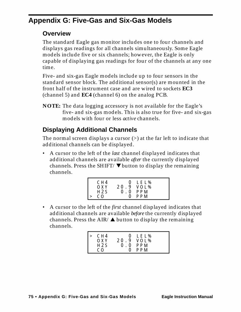
75 • Appendix G: Five-Gas and Six-Gas Models Eagle Instruction Manual
Appendix G: Five-Gas and Six-Gas Models
OverviewThe standard Eagle gas monitor includes one to four channels and displays gas readings for all channels simultaneously. Some Eagle models include five or six channels; however, the Eagle is only capable of displaying gas readings for four of the channels at any one time.
Five- and six-gas Eagle models include up to four sensors in the standard sensor block. The additional sensor(s) are mounted in the front half of the instrument case and are wired to sockets EC3 (channel 5) and EC4 (channel 6) on the analog PCB.
NOTE: The data logging accessory is not available for the Eagle’s five- and six-gas models. This is also true for five- and six-gas models with four or less active channels.
Displaying Additional ChannelsThe normal screen displays a cursor (>) at the far left to indicate that additional channels can be displayed.
• A cursor to the left of the last channel displayed indicates that additional channels are available after the currently displayed channels. Press the SHIFT/▼ button to display the remaining channels.
• A cursor to the left of the first channel displayed indicates that additional channels are available before the currently displayed channels. Press the AIR/▲ button to display the remaining channels.
C H 4O Y
C OH 2 S
X 2 0 . 90
00.0
LVPP
PP
MM
EO
LL
%%
>
C H 4O Y
C OH 2 S
X 2 0 . 90
00.0
LVPP
PP
MM
EO
LL
%%
>
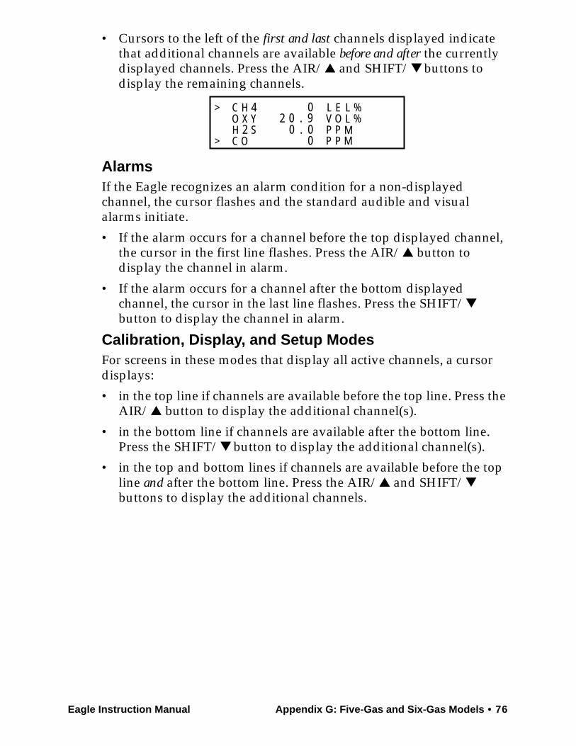
Eagle Instruction Manual Appendix G: Five-Gas and Six-Gas Models • 76
• Cursors to the left of the first and last channels displayed indicate that additional channels are available before and after the currently displayed channels. Press the AIR/▲ and SHIFT/▼ buttons to display the remaining channels.
AlarmsIf the Eagle recognizes an alarm condition for a non-displayed channel, the cursor flashes and the standard audible and visual alarms initiate.
• If the alarm occurs for a channel before the top displayed channel, the cursor in the first line flashes. Press the AIR/▲ button to display the channel in alarm.
• If the alarm occurs for a channel after the bottom displayed channel, the cursor in the last line flashes. Press the SHIFT/▼ button to display the channel in alarm.
Calibration, Display, and Setup ModesFor screens in these modes that display all active channels, a cursor displays:
• in the top line if channels are available before the top line. Press the AIR/▲ button to display the additional channel(s).
• in the bottom line if channels are available after the bottom line. Press the SHIFT/▼ button to display the additional channel(s).
• in the top and bottom lines if channels are available before the top line and after the bottom line. Press the AIR/▲ and SHIFT/▼ buttons to display the additional channels.
C H 4O Y
C OH 2 S
X 2 0 . 90
00.0
LVPP
PP
MM
EO
LL
%%
>
>
77 • Appendix H: Eagle Transformer Gas Tester Model Eagle Instruction Manual
Appendix H: Eagle Transformer Gas Tester Model
This Eagle Transformer Gas Tester Model is specially set up for electrical transformer gas testing. Large electrical transformers are filled with oil which surrounds the transformer coils, and they have an inert gas head space above the oil. When a transformer begins to fail, electrical arcing between the conductors of the coils can cause flammable gases to form in the head space. By testing the head space for these gases, and recording trends of the readings, an early warning of transformer failure can be determined, and the transformer can be removed from service before it explodes.
DescriptionThis combustible sensor, which is a catalytic combustion type, is calibrated to and the instrument is setup for hydrogen with a range of 0 - 5.00% volume. Since the headspace being tested is filled with nitrogen, there is not oxygen in the test sample. The catalytic sensor requires oxygen in order to operate, so the instrument is supplied with a snap-on dilution fitting with a dilution ratio of 1:1 (one part air to one part sample). This fitting blends the sample with ambient air before entering the instrument, which provides sufficient oxygen for the sensor to work. The instrument is also supplied with a sample bag.
Operation1. Turn the instrument on and allow it to warm up.
2. Attach the dilution fitting directly to the front of the instrument, and the plastic probe to the dilution fitting.
3. Press the “AIR” button in fresh air to zero the instrument.
4. Connect the deflated sample bag to the sample valve on the transformer, and open the valve slightly to fill the sample bag. Close off the sample bag and remove it from the transformer valve.
5. Attach the sample bag to the EAGLE probe, and open the sample bag.
The sample will now be drawn into the instrument. After about 45 seconds note and record the display reading. Compare this reading to historical data to determine the condition of the transformer.

Eagle Instruction Manual Appendix H: Eagle Transformer Gas Tester Model • 78
NOTE: The Eagle can be calibrated either with or without the dilution fitting in place. If calibrated without the dilution fitting in place, then display readings must be doubled to determine the actual gas concentration. If calibrated with the dilution fitting in place, then the sample bag must be used during calibration, and the display readings will be the actual gas concentrations.
CAUTION: If the dilution fitting is in place for calibration, do not use a demand flow regulator. Use a sample bag. The use of a demand flow regulator with a dilution fitting when calibrating will result in an inaccurate calibration.
AlarmsAll the gas alarms on the Transformer Gas Tester are set to OFF.
Part List
Table 17: Parts List: Eagle Tank Tester Model
Part Number Description
80-0405RK Dilution fitting (1:1)
81-1126RK Sample bag, 9” x 9”, tedlar
79 • Appendix I: Installing the Data Logger Board Eagle Instruction Manual
Appendix I: Installing the Data Logger Board
Appendix H describes the procedure to install the Eagle’s data logger board. The data logging feature is an optional accessory.
NOTE: Although the data logger board may be installed in the field, RKI Instruments, Inc. recommends that you return the Eagle to the factory for data logger board installation.
1. Take the Eagle to a non-hazardous location, and turn the power off.
2. Unscrew the two large screws on the top of the case, then carefully lift the top of the case and lay it aside.
3. Unplug the ribbon cable from the main circuit board in the top case.
4. Remove the two screws, flat washers, and lock washers that hold the main circuit board in the top case.
5. Slowly pull the main circuit board from the top case far enough to allow room to install the Data Logger board. Avoid pulling so far that you disconnect any of the four cables on the main circuit board.
6. Plug the Data Logger board into the main circuit board at CN1A, CN1B, CN1C, and CN1D.
7. Reassemble the main circuit board to the top case with the screws and lock washers removed in step 4.
8. Plug in the ribbon cable.
9. Reassemble and secure the top case to the bottom case.
10. Start the Eagle and program the Data Logger functions as described in “Setup Mode” on page 24.
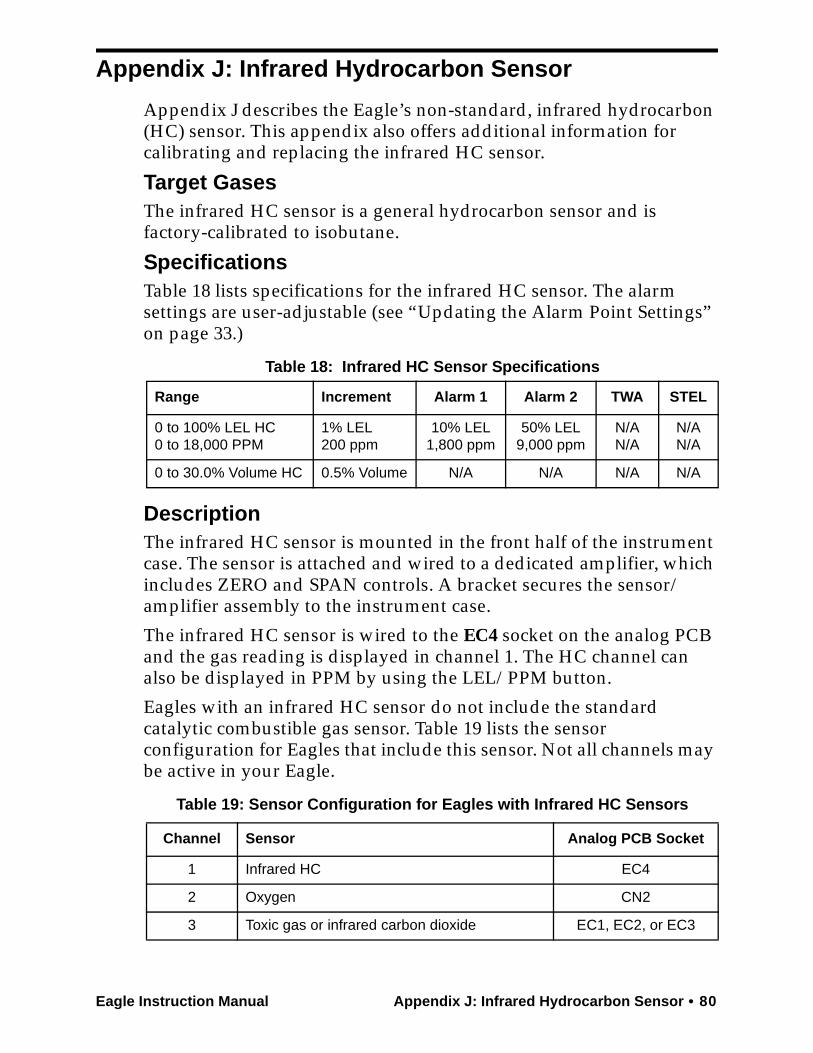
Eagle Instruction Manual Appendix J: Infrared Hydrocarbon Sensor • 80
Appendix J: Infrared Hydrocarbon Sensor
Appendix J describes the Eagle’s non-standard, infrared hydrocarbon (HC) sensor. This appendix also offers additional information for calibrating and replacing the infrared HC sensor.
Target GasesThe infrared HC sensor is a general hydrocarbon sensor and is factory-calibrated to isobutane.
SpecificationsTable 18 lists specifications for the infrared HC sensor. The alarm settings are user-adjustable (see “Updating the Alarm Point Settings” on page 33.)
DescriptionThe infrared HC sensor is mounted in the front half of the instrument case. The sensor is attached and wired to a dedicated amplifier, which includes ZERO and SPAN controls. A bracket secures the sensor/amplifier assembly to the instrument case.
The infrared HC sensor is wired to the EC4 socket on the analog PCB and the gas reading is displayed in channel 1. The HC channel can also be displayed in PPM by using the LEL/PPM button.
Eagles with an infrared HC sensor do not include the standard catalytic combustible gas sensor. Table 19 lists the sensor configuration for Eagles that include this sensor. Not all channels may be active in your Eagle.
Table 18: Infrared HC Sensor Specifications
Range Increment Alarm 1 Alarm 2 TWA STEL
0 to 100% LEL HC0 to 18,000 PPM
1% LEL200 ppm
10% LEL1,800 ppm
50% LEL9,000 ppm
N/AN/A
N/AN/A
0 to 30.0% Volume HC 0.5% Volume N/A N/A N/A N/A
Table 19: Sensor Configuration for Eagles with Infrared HC Sensors
Channel Sensor Analog PCB Socket
1 Infrared HC EC4
2 Oxygen CN2
3 Toxic gas or infrared carbon dioxide EC1, EC2, or EC3

81 • Appendix J: Infrared Hydrocarbon Sensor Eagle Instruction Manual
Calibrating the Infrared HC SensorRecommended calibration frequency for the infrared HC sensor is once every 3 months. Enter Calibration mode and calibrate the infrared HC sensor using the same procedure as the standard combustible gas sensor (see “Calibration” on page 42). Be sure to use 50% LEL isobutane to calibrate the infrared HC sensor, not methane. If calibrating only an infrared HC channel, use a 50% LEL isobutane cylinder and the single calibration method. If calibrating multiple channels that include infrared HC, oxygen, CO, or H2S, use a 4-gas mix calibration cylinder with isobutane and the auto calibration method. If calibrating other channel types, use an appropriate calibration cylinder and the single calibration method.
Adjusting the Sensor Controls
CAUTION:Only perform the following steps if you are unable to set the correct calibration reading with the AIR/▲ and SHIFT/▼ buttons.
1. Use the AIR/▲ and SHIFT/▼ buttons to set the reading to the middle of the range in which you can currently adjust the reading. For example, if you can set the reading from a minimum of 10% LEL to a maximum of 40% LEL, set the display to 25% LEL.
2. Unscrew the two large screws on the top of the case, then carefully lift the top of the case and lay it aside.
3. Locate the infrared HC sensor in the front half of the bottom case. It is connected to the EC4 socket on the analog PCB.
4. Adjust the sensor’s SPAN control one turn and observe the display reading. Continue to adjust the SPAN control until the display reading matches the concentration of the calibration cylinder.
The SPAN control is on the top edge of the amplifier and is the control closest to the front of the instrument.
5. Place the top of the case in its original position, then secure it with the large screws you loosened in step 5.
6. Continue with the normal calibration procedure.
4 Toxic gas or infrared carbon dioxide EC1, EC2, or EC3
Table 19: Sensor Configuration for Eagles with Infrared HC Sensors
Channel Sensor Analog PCB Socket
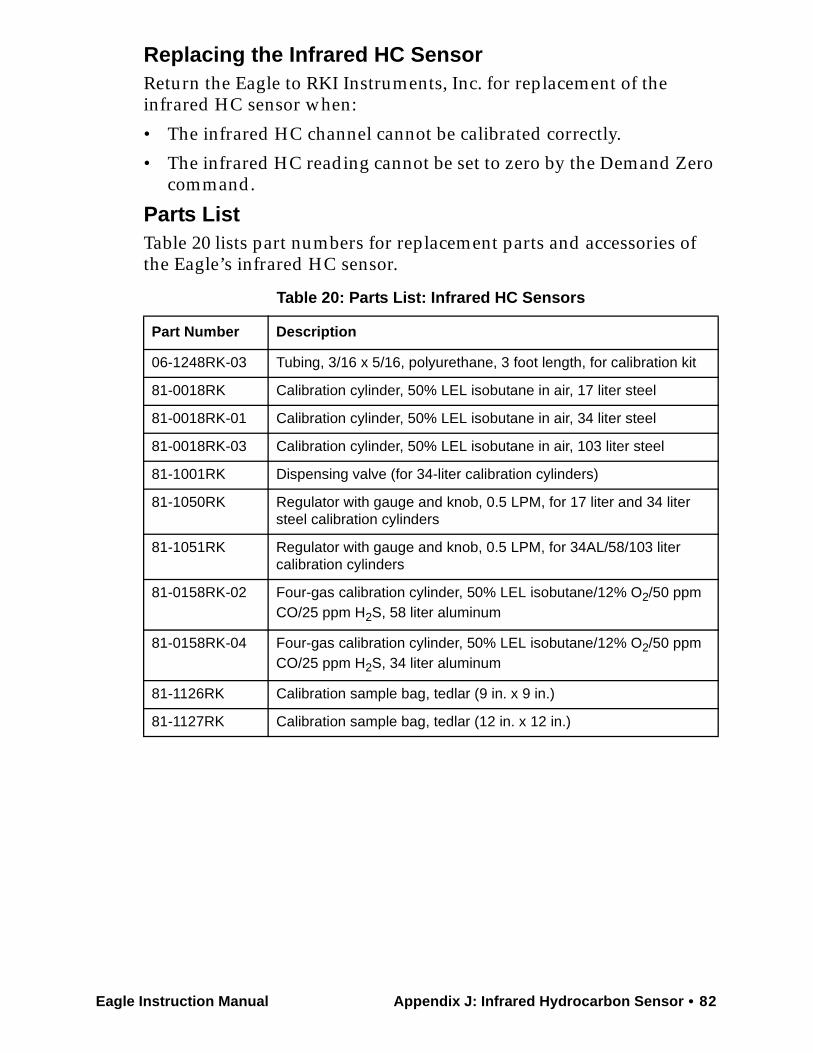
Eagle Instruction Manual Appendix J: Infrared Hydrocarbon Sensor • 82
Replacing the Infrared HC SensorReturn the Eagle to RKI Instruments, Inc. for replacement of the infrared HC sensor when:
• The infrared HC channel cannot be calibrated correctly.
• The infrared HC reading cannot be set to zero by the Demand Zero command.
Parts ListTable 20 lists part numbers for replacement parts and accessories of the Eagle’s infrared HC sensor.
Table 20: Parts List: Infrared HC Sensors
Part Number Description
06-1248RK-03 Tubing, 3/16 x 5/16, polyurethane, 3 foot length, for calibration kit
81-0018RK Calibration cylinder, 50% LEL isobutane in air, 17 liter steel
81-0018RK-01 Calibration cylinder, 50% LEL isobutane in air, 34 liter steel
81-0018RK-03 Calibration cylinder, 50% LEL isobutane in air, 103 liter steel
81-1001RK Dispensing valve (for 34-liter calibration cylinders)
81-1050RK Regulator with gauge and knob, 0.5 LPM, for 17 liter and 34 liter steel calibration cylinders
81-1051RK Regulator with gauge and knob, 0.5 LPM, for 34AL/58/103 liter calibration cylinders
81-0158RK-02 Four-gas calibration cylinder, 50% LEL isobutane/12% O2/50 ppm CO/25 ppm H2S, 58 liter aluminum
81-0158RK-04 Four-gas calibration cylinder, 50% LEL isobutane/12% O2/50 ppm CO/25 ppm H2S, 34 liter aluminum
81-1126RK Calibration sample bag, tedlar (9 in. x 9 in.)
81-1127RK Calibration sample bag, tedlar (12 in. x 12 in.)