Embed Size (px)
Citation preview

Instruction ManualIM/AM Issue 15
Electromagnetic FlowmeterAquaMaster™

ABBEN ISO 9001:2000
Cert. No. Q 05907
EN 29001 (ISO 9001)
Lenno, Italy – Cert. No. 9/90A
Stonehouse, U.K.
����
Electrical Safety
This equipment complies with the requirements of CEI/IEC 61010-1:2001-2 'Safety Requirements for ElectricalEquipment for Measurement, Control and Laboratory Use'. If the equipment is used in a manner NOT specified by theCompany, the protection provided by the equipment may be impaired.
Symbols
One or more of the following symbols may appear on the equipment labelling:
Warning – Refer to the manual for instructions Direct current supply only
Caution – Risk of electric shock Alternating current supply only
Protective earth (ground) terminal Both direct and alternating current supply
Earth (ground) terminal The equipment is protected through double insulation
The Company
We are an established world force in the design and manufacture of instrumentation forindustrial process control, flow measurement, gas and liquid analysis and environmentalapplications.
As a part of ABB, a world leader in process automation technology, we offer customersapplication expertise, service and support worldwide.
We are committed to teamwork, high quality manufacturing, advanced technology andunrivalled service and support.
The quality, accuracy and performance of the Company’s products result from over 100years experience, combined with a continuous program of innovative design anddevelopment to incorporate the latest technology.
The UKAS Calibration Laboratory No. 0255 is just one of the ten flow calibration plantsoperated by the Company and is indicative of our dedication to quality and accuracy.
Information in this manual is intended only to assist our customers in the efficient operation of our equipment. Use of thismanual for any other purpose is specifically prohibited and its contents are not to be reproduced in full or part withoutprior approval of the Technical Publications Department.
Health and Safety
To ensure that our products are safe and without risk to health, the following points must be noted:
1. The relevant sections of these instructions must be read carefully before proceeding.2. Warning labels on containers and packages must be observed.3. Installation, operation, maintenance and servicing must only be carried out by suitably trained personnel and in accordance
with the information given.4. Normal safety precautions must be taken to avoid the possibility of an accident occurring when operating in conditions of
high pressure and/or temperature.5. Chemicals must be stored away from heat, protected from temperature extremes and powders kept dry. Normal safe
handling procedures must be used.6. When disposing of chemicals ensure that no two chemicals are mixed.
Safety advice concerning the use of the equipment described in this manual or any relevant hazard data sheets (where applicable) may be obtained from the Company address on the back cover, together with servicing and spares information.

Electromagnetic FlowmeterAquaMaster™
IM/AM Issue 15 1
1 Introduction ...................................................................................................................................... 3
2 Mechanical Installation .................................................................................................................... 42.1 Unpacking ............................................................................................................................... 42.2 Installation Conditions .............................................................................................................. 42.3 Transmitter Dimensions ........................................................................................................... 9
2.3.1 Terminal Box – Sensor-mounted ................................................................................... 92.3.2 AquaMaster ................................................................................................................. 10
2.4 GSM-equipped Transmitters .................................................................................................. 112.4.1 GSM Antenna Installation ............................................................................................ 112.4.2 Connecting a Remote Antenna .................................................................................... 122.4.3 Installing a SIM Card .................................................................................................... 13
3 Electrical Installation ..................................................................................................................... 143.1 Grounding ............................................................................................................................. 143.2 Connections .......................................................................................................................... 16
3.2.1 Sensor Terminal Box Connections (Remote Versions only) .......................................... 163.2.2 AquaMaster Connections ............................................................................................ 17
3.3 Input/Output Connections ..................................................................................................... 193.3.1 Frequency Outputs – AquaMaster ............................................................................... 193.3.2 Alarm Interface ............................................................................................................ 193.3.3 19-Pin MIL Connector Input/Output Connections – AquaMaster ................................. 203.3.4 7-Pin MIL Connector Input/Output Connections – AquaMaster ................................... 213.3.5 ScanReader Interface (Option) ..................................................................................... 213.3.6 Local Computer Connection ........................................................................................ 223.3.7 Remote Computer Connection (RS232C Option) ......................................................... 233.3.8 Anti-Tamper Protection ............................................................................................... 243.3.9 Power Supply Connections ......................................................................................... 253.3.10 Pressure Transducer (Optional) .................................................................................. 263.3.11 Environmental Protection ........................................................................................... 27
4 Start-Up And Operation ................................................................................................................. 284.1 Connecting Batteries ............................................................................................................. 284.2 Start-up ................................................................................................................................. 294.3 Display Activation .................................................................................................................. 294.4 Replacing a Battery ............................................................................................................... 30
4.4.1 Spares Kits .................................................................................................................. 304.4.2 Battery Changing Procedures ...................................................................................... 31
4.5 Servicing Plugs and Sockets .................................................................................................. 334.5.1 Service Intervals .......................................................................................................... 334.5.2 Equipment Required .................................................................................................... 334.5.3 Preparation .................................................................................................................. 344.5.4 Disconnection ............................................................................................................. 344.5.5 Order of Treatment ...................................................................................................... 354.5.6 Stage 1 – Oxide Removal and Cleaning ....................................................................... 354.5.7 Stage 2 – Oxide Prevention ......................................................................................... 364.5.8 Completion Tasks ........................................................................................................ 36
4.6 Accessories/Spares Kits ........................................................................................................ 36

Electromagnetic FlowmeterAquaMaster™
2 IM/AM Issue 15
5 Specification – Sensor ................................................................................................................... 37
Specification – Transmitter ............................................................................................................ 41
Appendix A Hazardous Area Protection ............................................................................................. 49A.1 GSM-Equipped Units – Safety Precautions ............................................................................49
Notes 52

Electromagnetic FlowmeterAquaMaster™ 1 Introduction
IM/AM Issue 15 3
1 IntroductionAquaMasterTM is a range of high performance electromagnetic flowmeters for the measurement ofelectrically conductive fluids and are normally supplied as factory configured, calibrated systems.
This manual provides end-user details for AquaMaster Integral and Remote transmitters. For details of thesensor used with the transmitter, please refer to the sensor manual supplied at time of ordering.
Warning.
� Installation and maintenance must be carried out only by suitably trained personnel.
� Read all relevant sections of this manual before selecting a location.
� The safety requirements of this equipment, any associated equipment and the local environment must be taken into consideration during installation.
� Install and use this equipment in accordance with relevant national and local standards.
� Specific safety precautions apply to the use of the GSM engine which forms part of the GSM-equipped version of this product. If the unit purchased has GSM-capability, read Appendix A on page 49 before selecting a location.

Electromagnetic FlowmeterAquaMaster™ 2 Mechanical Installation
4 IM/AM Issue 15
2 Mechanical Installation
2.1 Unpacking
2.2 Installation Conditions
Fig. 2.1 Unpacking
Caution. Do NOT exceed the maximum working pressure marked on the equipment.
Fig. 2.2 Spillage
Fig. 2.3 Vibration

Electromagnetic FlowmeterAquaMaster™ 2 Mechanical Installation
IM/AM Issue 15 5
Fig. 2.4 Localized Heat
Fig. 2.5 Siting
Fig. 2.6 Within Temperature Limits
Fig. 2.7 Straight Pipe Requirements
Allow Room to Read Display
–10 °C(14 °F)
Minimum
80 °C (176 °F) Maximum
0 x Pipe Dia. 0 x Pipe Dia.
Minimum Minimum
Flow Direction

Electromagnetic FlowmeterAquaMaster™ 2 Mechanical Installation
6 IM/AM Issue 15
Fig. 2.8 Fluid Level
Fig. 2.9 Shade
Fig. 2.10 Above Ground
Fig. 2.11 Temperature Difference
Supports

Electromagnetic FlowmeterAquaMaster™ 2 Mechanical Installation
IM/AM Issue 15 7
Fig. 2.12 Underground
Note. For further details when burying flow sensors contact the ABB Service Organisation.
Fig. 2.13 Cable Routing
Fig. 2.14 Gasket Fitting
AdequateProtection Plate(Recommended)
Backfill
Fit Gaskets Gaskets SameSize as Pipe

Electromagnetic FlowmeterAquaMaster™ 2 Mechanical Installation
8 IM/AM Issue 15
Fig. 2.15 Access to Transmitter
Fig. 2.16 Separation of Sensors
For Access to Display, and Communication Connector
0.7 m (2.3 ft) Minimum

Electromagnetic FlowmeterAquaMaster™ 2 Mechanical Installation
IM/AM Issue 15 9
2.3 Transmitter Dimensions
2.3.1 Terminal Box – Sensor-mounted
Dimensions in mm (in)
Fig. 2.17 AquaMaster terminal box
Dimensions in mm (in)
Fig. 2.18 Round Terminal Box
61 (2.4)
M20 Cable Gland Shown
95 (3.75)
80 (3.15)30 (1.2)
100 (3.93)
36.5 (1.43)
62 (2.44)
80 (3.2)

Electromagnetic FlowmeterAquaMaster™ 2 Mechanical Installation
10 IM/AM Issue 15
2.3.2 AquaMaster
Fig. 2.19 AquaMaster– Dimensions
��������
Dimensions in mm (in)
Installation and Wiring Access
300 (11.8) Minimum 450 (17.7) Preferred
Allowance for Cable Bend ~ Each Side130 (5.10) – Standard)230 (9.0) – Armored)
Transmitter Mounting Plate(Remote Only)
146 (5.75)125 (4.90)
176 (7.0)
155 (6.10)170
(6.07)
150 (5.90)
140 (5.50)
Ø6.5 (0.25)
Ø13 (0.50)
Ø6.5 (0.25)
105 (4.13)

Electromagnetic FlowmeterAquaMaster™ 2 Mechanical Installation
IM/AM Issue 15 11
2.4 GSM-equipped Transmitters
2.4.1 GSM Antenna InstallationBefore deciding on an antenna mounting location, check that the local signal strength for the chosenmobile phone network is satisfactory. Use the GSM-equipped transmitter's integral signal strength testfacility to establish signal strength. Refer to 'Commissioning test for signal strength' in the Quick ReferenceGuide for the AquaMaster S with GSM (IM/AMG–QRG).
If a GSM-equipped transmitter is not available, a standard mobile phone on the same network, positionedas close as possible to the intended location, will give a good indication of local signal strength. For GSMand logger download services, a minimum of two visible signal strength indicator 'bars' are recommended.For SMS text, a minimum of one visible signal strength indicator 'bar' is recommended.
The following must also be observed when deciding on the antenna mounting location:
� For best results, mount the antenna as high above local ground level as possible.
� If the antenna must be mounted below ground, achieve optimum results by ensuring:
– there is a strong mobile phone network signal at ground level
– the antenna is mounted 50 mm below the chamber cover, which must be plastic – seeFig. 2.20
� Ensure the antenna will not become submerged under water – see Fig. 2.20.
� Metallic enclosures will seriously degrade the signal. If an enclosure is used it must be non-metallic.
� Do not mount the antenna closer than 50 mm to any solid wall or surface – see Fig. 2.21.
� Do not mount the antenna beneath a solid surface (e.g. metal cover, floor/ceiling, etc).
Fig. 2.20 GSM Antenna Installation
Remote Antenna Integral Antenna
50 mm (2.0 in) 50 mm (2.0 in)

Electromagnetic FlowmeterAquaMaster™ 2 Mechanical Installation
12 IM/AM Issue 15
2.4.2 Connecting a Remote Antenna
Fig. 2.21 GSM Antenna Installation
Fig. 2.22 Connecting a Remote Antenna – AquaMaster
>50 mm (2.0 in)
�
�
�
�
�
�
If the transmitter is not fixed in any way, arrange or hold it with the top cover uppermost.
Wash off any loose dirt from the case using plain water.
Remove the transmitter top cover and battery mounting tray – see Fig. 3.7.
Attach the antenna cable plug securely to the antenna connector.
Pass the antenna cable through a spare cable gland.
Tighten the cable gland.
Refit the battery mounting tray and the transmitter top cover – see Fig. 3.7.
SIM cardholder

Electromagnetic FlowmeterAquaMaster™ 2 Mechanical Installation
IM/AM Issue 15 13
2.4.3 Installing a SIM Card
Fig. 2.23 Installing a SIM Card – AquaMaster
�
�
�
�
�
�
If the transmitter is not fixed in any way, arrange or hold it with the top cover uppermost.
Wash off any loose dirt from the case using plain water.
Remove the transmitter top cover and battery mounting tray – see Fig. 3.7.
Slide to unlock and open the SIMcard holder cover.
Close the SIM card holder cover and slide into locked position.
Insert the SIM card, contact side down and bevelled edge first, into the SIM card holder.
Refit the battery mounting tray and the transmitter top cover – see Fig. 3.7.

Electromagnetic FlowmeterAquaMaster™ 3 Electrical Installation
14 IM/AM Issue 15
3 Electrical Installation
3.1 Grounding
Caution. For safety reasons and optimum performance, the flowmeter, pipelines and medium must be correctly bonded and grounded according to regulations.
Note.
� Connect the transmitter ground connection to the flowmeter body ground – see Fig. 3.3 and Fig. 3.4.
� The flow sensor must not be connected to a ground spike.
� For bonding connections use ≥4 mm2 (<10AWG) cable.
� Older sensors from DN40 to DN80, that are fitted with bare metal stainless steel flanges, do notrequire fluid contact rings.
Fig. 3.1 All Metal Pipe, Including Lined Metal Pipe
Fig. 3.2 All Metal pipe, including lined metal pipe. Also sizes DN40, DN50 & DN80 if fitted with bare metal stainless steelflanges
Fluid Contact Rings
See Figs. 3.3 and 3.4
See Figs. 3.3 and 3.4

Electromagnetic FlowmeterAquaMaster™ 3 Electrical Installation
IM/AM Issue 15 15
Fig. 3.3 Battery-powered AquaMaster Transmitter Mounted in a Chamber
Fig. 3.4 Mains- or Battery-powered AquaMaster Transmitter Mounted in a Cabinet

Electromagnetic FlowmeterAquaMaster™ 3 Electrical Installation
16 IM/AM Issue 15
3.2 Connections
3.2.1 Sensor Terminal Box Connections (Remote Versions only)
Caution. (Remote versions)
� Remove foil screens completely, and plastic/foil screens and any fillers
� Twist the three screen wires together and sleeve them.
� Keep cable pairs twisted.
� Make connections only as shown.
� Maintain Environmental Protection at all times.
� Conduit connections must provide cable entry sealing.
Fig. 3.5 Sensor Terminal Box Connections (Remote Version)
Caution. With Belden Cable 8777, ensure that the black wires are not interchanged and remain with the associated pair.
Fig. 3.6 Round Sensor Terminal Block Connections
CABLEABB Belden 8777
Violet White
Blue Black
Green Sleeved Ground
Yellow Red
Orange Black
Red Green
Brown Black
Maximum Cable LengthsSTT 4002 Series: 80 mSTT 4006/4007 Series: 250 mBelden 8777: 80 m
Drain/Screen
Wire toInternal Earth
for NPTGland
Cut cables to 60 mm (2.35 in)
Violet
Blue
Green
Yellow
Orange
Red
Brown
Drain/Screen Wire for M20 Gland

Electromagnetic FlowmeterAquaMaster™ 3 Electrical Installation
IM/AM Issue 15 17
3.2.2 AquaMaster Connections
Caution.
� To ensure cable glands seal, use cable of diameter 2 to 6 mm (0.08 to 0.24 in) [M16] only.
� Ensure cable glands are tightened after wiring. However, overtightening a plastic cable gland will break it and destroy its sealing property. It is recommended that cable glands are tightened fingertight initially, then a further 1/2 to 3/4 turn applied using a suitable spanner.
� Ensure that ‘O’ ring seals and mating surfaces are clean, to maintain environmental rating.
� For IP68 protection where the transmitter could be submerged, the termination area must be potted – see Section 3.3.9.
Note. The batteries are mounted in the lid of early style transmitters.
Fig. 3.7 AquaMaster – Connection Terminal Access
Fig. 3.8 AquaMaster – Connections (Glands/Conduit Entry)
�
�
Slacken Captive ScrewsLift offCover
Remove Battery Tray
...Lift
Press and ...

Electromagnetic FlowmeterAquaMaster™ 3 Electrical Installation
18 IM/AM Issue 15
Caution. (Remote versions)
� Remove foil screens completely, and plastic/foil screens and any fillers
� Twist the three screen wires together and sleeve them.
� Keep cable pairs twisted.
� Make connections only as shown.
� Maintain Environmental Protection at all times.
� Conduit connections must provide cable entry sealing.
Fig. 3.9 AquaMaster – Sensor Cable Connections (Connector, Remote version)

Electromagnetic FlowmeterAquaMaster™ 3 Electrical Installation
IM/AM Issue 15 19
3.3 Input/Output Connections
3.3.1 Frequency Outputs – AquaMaster
3.3.2 Alarm Interface
Caution.
� Refer to the associated Data Sheets for input/output ratings.
� Inductive loads must be suppressed or clamped to limit voltage swings
� Operation of outputs is programmable – see Quick Reference Programming Guide for details.
� External isolators are not normally required as the pulse and alarm circuit is electrically separated from all other AquaMaster connections.
� Capacitive loads must be inrush current limited.
� Fully-floating pulse outputs may be subject to static damage, e.g. connecting to a floating datalogger, unless 'COM' is operated within its galvanic isolation range (±35 V) from earth.
Fig. 3.10 Frequency Output Connections – AquaMaster
Note. Outputs 1 & 2 are not polarity sensitive. The common connection for these outputs is designated ‘COM’.
Fig. 3.11 Alarm Output Connections – AquaMaster
Note. Output 3 is not polarity sensitive. The common connection for these outputs is designated ‘COM’. Alarm functions are available only with product software versions: ≥ 1.1 (Release 1) ≥ 2.1 (release 2). See Programming Guide to determine software version.
�����������
���� ������ � � � � �
� � � � � �
Telemetry, Electronic Counters etc.
Counter/Totalizers
*Optional link for grounding floating output. See Caution above.PLC or Datalogger
Common
Input 1
Input 2
COM
O/P1
O/P2
I/POV*
COMO/P1
O/P2
I/PO
V
CO
MO
/P1
O/P
2and/or
Common
Alarm Input
COM
O/P 3

Electromagnetic FlowmeterAquaMaster™ 3 Electrical Installation
20 IM/AM Issue 15
3.3.3 19-Pin MIL Connector Input/Output Connections – AquaMaster
Fig. 3.12 AquaMaster – 19-Pin MIL Connector Connections
Pin Signal Function Color (Output Cable)
A – Reserved
B – Reserved
C – Reserved
D O/P 1 Forward Pulses or Forward & Reverse Pulses Orange
E O/P 3 Alarm Output White/Red
# When Remote Comms. Option is fittedF O/P 2 Reverse Pulses or Direction Indicator Blue
G O/P Com† Common Drain Wire/Screen
H – Reserved *Not fitted on older cables
J I/P Gnd Input Common White
K I/P+ Contact Input Violet † Note Caution regarding fully floating outputs. Recommended protection for floating output systems is to connect G to J.
L RXD Receive data (serial input connection) # Turquoise
M TXD Transmit data (serial output connection) # Brown
N RTS Request to send # Red/Black *
P CTS Clear to send # Yellow/Red *
R – Reserved
S – Reserved
T RI Ring Indicator # Yellow
U – Reserved
V Serial GND Comms Ground # Green
Table 3.1 AquaMaster – 19-Pin MIL Connector Connections
��
�
�
�
�
�
��
�
�
�
�
�
�
�
!
"

Electromagnetic FlowmeterAquaMaster™ 3 Electrical Installation
IM/AM Issue 15 21
3.3.4 7-Pin MIL Connector Input/Output Connections – AquaMaster
3.3.5 ScanReader Interface (Option)
Fig. 3.13 AquaMaster – 7-Pin MIL Connector Connections
Pin Signal Function Color (Output Cable)
A +V ScanReader +V Violet
B Data ScanReader Blue
C O/P COM Output Common Yellow
D O/P 2 Reverse Pulse or Direction Indicator Red
E O/P 3 Alarm Output Brown
F O/P 1 Forward Pulse or Direction Indicator Orange
G 0V ScanReader 0V Green
Table 3.2 AquaMaster – 7-Pin MIL Connector Connections
Fig. 3.14 ScanReader Connections
�
�
�
�
�
��
#"
#"
$"
1.5 m (4.9 ft) to 40 m (131 ft)Reading Pad
Recommended Cable ABB STT4009(or equivalent)
2-Wire Pad Connection
3-Wire Transponder Connection
Data
Transponder3-Terminal PCBWAD2026
Data
Cable ColorsGreen +V
Red Data
Black 0V

Electromagnetic FlowmeterAquaMaster™ 3 Electrical Installation
22 IM/AM Issue 15
3.3.6 Local Computer Connection
Fig. 3.15 Local Computer Connections – AquaMaster
Connected to 9-pin Serial Data socket on PDA or PC via 'Laplink' lead/adaptor
Original Style
Current Style
ABB LimitedPart No.WEBC2000
9-Pin Male(for link lead to Psion)
9-Pin Female(direct to PC)
Electromagnetic FlowmeterAquaMaster™ 3 Electrical Installation
IM/AM Issue 15 23
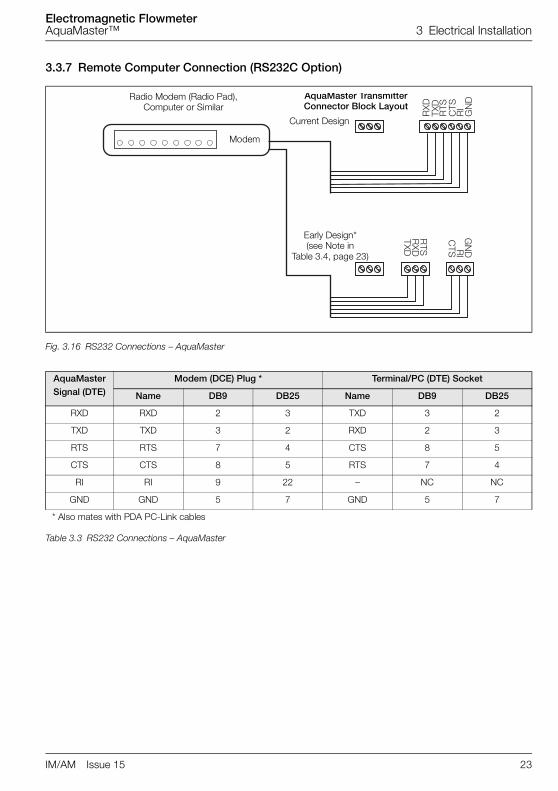
3.3.7 Remote Computer Connection (RS232C Option)
Fig. 3.16 RS232 Connections – AquaMaster
AquaMaster Signal (DTE)
Modem (DCE) Plug * Terminal/PC (DTE) Socket
Name DB9 DB25 Name DB9 DB25
RXD RXD 2 3 TXD 3 2
TXD TXD 3 2 RXD 2 3
RTS RTS 7 4 CTS 8 5
CTS CTS 8 5 RTS 7 4
RI RI 9 22 – NC NC
GND GND 5 7 GND 5 7
* Also mates with PDA PC-Link cables
Table 3.3 RS232 Connections – AquaMaster
� �
�%�
%�
���
�&
� �
� �
�%�
%�
����&
� �
Radio Modem (Radio Pad), Computer or Similar
Modem
AquaMaster TransmitterConnector Block Layout
Early Design*(see Note in
Table 3.4, page 23)
Current Design

Electromagnetic FlowmeterAquaMaster™ 3 Electrical Installation
24 IM/AM Issue 15
3.3.8 Anti-Tamper ProtectionIn some applications, such as those covered by the Measuring Instruments Directive (MID) 2004/22/EEC orOIML R49 the flowmeter can be sealed to prevent unauthorized changes to the instrument settings andconfiguration. A "read only" switch is used as detailed in Fig. 3.17, which prevents login through anycommunication means and modification of any parameters on the AquaMaster / Explorer. Physical securitytags / seals can be fitted which detect unauthorised physical access as shown in Fig. 3.18.
Fig. 3.17 Location of the Read Only switch
Fig. 3.18 Security Tagging
Note. Suitable security tags should be applied to detect unauthorised physical access.
J10
Switch Position Up (Towards cover) = Normal Operation with Parameter Change permitted.
Switch Position Down = "Read Only" – Login and parameter change inhibited.
Security tag and seal

Electromagnetic FlowmeterAquaMaster™ 3 Electrical Installation
IM/AM Issue 15 25
3.3.9 Power Supply Connections
Warning.
� DISCONNECT THE SUPPLY FROM ANY CABLES BEING TERMINATED ON THETRANSMITTER.
� Electrical installation and earthing (grounding) must be in accordance with relevant national andlocal standards.
Note. Power supply connections/earthing arrangements are identical for cathodically protected remote transmitter systems. For cathodically protected integral transmitter systems, follow cathodic installation practices.
Fig. 3.19 Power Supply Connections – AquaMaster
���'�()(�*�� ��'�+���+�'�+�� �����&���!���,''-�".��#"��/��"�$����0��12�3����+�!��'��4&��5��*'(6'!�
��4���4��
AC Powervia a Suitable
Isolator and Fuse
Internal
External
>4 mm2
(<10 A.W.G.)Copper Wire
Transmitter Label Transmitter End View

Electromagnetic FlowmeterAquaMaster™ 3 Electrical Installation
26 IM/AM Issue 15
3.3.10 Pressure Transducer (Optional)Optional pressure transducer cables are available for a range of pressures and cable lengths.
Fig. 3.20 AquaMaster fitted with Optional Pressure Transducer Connector
Caution. Use only the pressure transducer supplied with the transmitter. Use of other pressure transducers will require alteration of the pressure span and zero factors in the transmitter.
PressureTransducerConnector

Electromagnetic FlowmeterAquaMaster™ 3 Electrical Installation
IM/AM Issue 15 27
3.3.11 Environmental Protection
Warning.
� Potting materials are toxic – use suitable safety precautions.
� Read the manufacturers instructions carefully before preparing the potting material.
Fig. 3.21 Potting the AquaMaster Transmitter
Caution.
� For IP68 protection against water ingress, pot the termination area on the metal transmitter versions.
� Check all connections and operations before potting.
� Do not overfill or allow the potting material to come into contact with O-rings or grooves; allow for inserting battery tray.
� Do not let potting material enter conduit(s), if used.
� Insert battery tray into potting before it sets and pull through the battery connection wires, thereby ensuring they are above the potting level.
� Keep unit upright whilst potting sets (minimum – two hours).
� Insert battery tray into potting before it sets and pull through the battery connection wires, thereby ensuring they are above the potting level.
Electromagnetic FlowmeterAquaMaster™ 4 Start-Up And Operation
28 IM/AM Issue 15
4 Start-Up And Operation
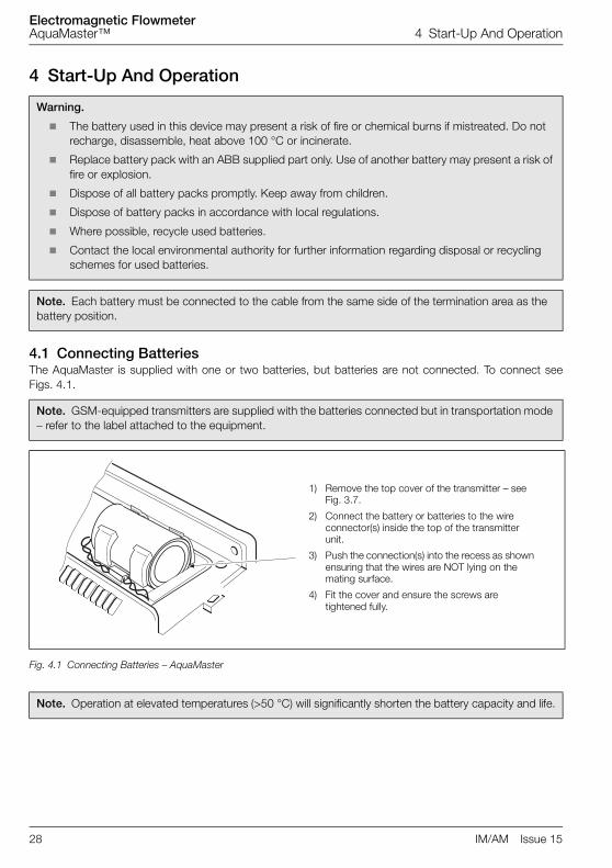
4.1 Connecting BatteriesThe AquaMaster is supplied with one or two batteries, but batteries are not connected. To connect seeFigs. 4.1.
Warning.
� The battery used in this device may present a risk of fire or chemical burns if mistreated. Do not recharge, disassemble, heat above 100 °C or incinerate.
� Replace battery pack with an ABB supplied part only. Use of another battery may present a risk of fire or explosion.
� Dispose of all battery packs promptly. Keep away from children.
� Dispose of battery packs in accordance with local regulations.
� Where possible, recycle used batteries.
� Contact the local environmental authority for further information regarding disposal or recycling schemes for used batteries.
Note. Each battery must be connected to the cable from the same side of the termination area as the battery position.
Note. GSM-equipped transmitters are supplied with the batteries connected but in transportation mode – refer to the label attached to the equipment.
Fig. 4.1 Connecting Batteries – AquaMaster
Note. Operation at elevated temperatures (>50 °C) will significantly shorten the battery capacity and life.
1) Remove the top cover of the transmitter – see Fig. 3.7.
2) Connect the battery or batteries to the wire connector(s) inside the top of the transmitter unit.
3) Push the connection(s) into the recess as shown ensuring that the wires are NOT lying on the mating surface.
4) Fit the cover and ensure the screws are tightened fully.

Electromagnetic FlowmeterAquaMaster™ 4 Start-Up And Operation
IM/AM Issue 15 29
4.2 Start-upRemove any plastic film from the AquaMaster light sensitive display window before commencing normaloperation.
When electrical power is connected, or the plastic film is removed from the display window with electricalpower connected, the AquaMaster performs a self-test operation. If successful, 'Pass' is indicated in thedisplay window.
If the display shows 'Err 1', check the sensor wiring. If the fault is rectified, the transmitter restartsautomatically.
If the display shows 'Err 2 or 3', contact ABB.
4.3 Display ActivationFor normal operation, activate the light sensitive display by first covering the display area totally.
On removing the covering, the display activates and cycles through the programmed set of displaymeasurements.
Fig. 4.2 Location of Controls
Note. For the use of local or remote serial communication and how to alter the displayed set of measurements, or instrument setup, see the Quick Reference Programming Guide.
Lower Display
Time
Flow Velocity
Pressure
Left Battery Warning
Sensor Fault
Empty Pipe condition
Mains Failure
Right Battery Warning
Upper Display
Date
Forward Flow Total
Reverse Flow Total
Net Flow Total
Pictorial Displays
Warning Annunciators

Electromagnetic FlowmeterAquaMaster™ 4 Start-Up And Operation
30 IM/AM Issue 15
4.4 Replacing a Battery
Normal Operation
If both batteries are good, no battery icons are displayed.
Replace Battery
When a single, steady battery icon is shown, replace the cellon the side indicated – in this example, the right-hand battery.Wait approximately three seconds after disconnecting thebattery before connecting the new battery. DO NOT change abattery if its associated icon is flashing.
Battery Pack Exhausted
Important. If both batteries require replacement, first changethe cell indicated by the steady icon – in this example, the leftbattery. The flashing icon indicates the battery currently in use.
4.4.1 Spares Kits
Note. Each battery must be connected to the cable from the same side of the termination area as the battery position in the battery holder or lid. For dual battery units, replace only the battery indicated by the battery legend described below.
Previous Model (domed cover version) Part Number
Battery Kit comprises 1 battery and one seal MEFA 9949
Lid assembly MEFA 9950
Table 4.1 AquaMaster Transmitter – Previous Model
Electromagnetic FlowmeterAquaMaster™ 4 Start-Up And Operation
IM/AM Issue 15 31
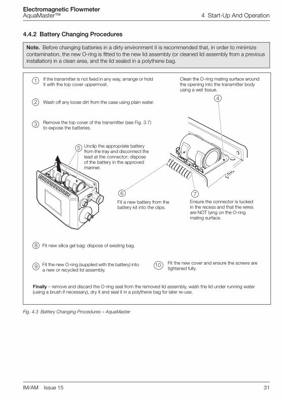
4.4.2 Battery Changing Procedures
Note. Before changing batteries in a dirty environment it is recommended that, in order to minimize contamination, the new O-ring is fitted to the new lid assembly (or cleaned lid assembly from a previous installation) in a clean area, and the lid sealed in a polythene bag.
Fig. 4.3 Battery Changing Procedures – AquaMaster
�
�
�
�
� �
5
- �#
If the transmitter is not fixed in any way, arrange or hold it with the top cover uppermost.
Wash off any loose dirt from the case using plain water.
Remove the top cover of the transmitter (see Fig. 3.7) to expose the batteries.
Unclip the appropriate battery from the tray and disconnect the lead at the connector; dispose of the battery in the approved manner.
Clean the O-ring mating surface around the opening into the transmitter body using a wet tissue.
Fit a new battery from the battery kit into the clips.
Ensure the connector is tucked in the recess and that the wires are NOT lying on the O-ring mating surface.
Fit new silica gel bag; dispose of existing bag.
Fit the new O-ring (supplied with the battery) into a new or recycled lid assembly.
Fit the new cover and ensure the screws are tightened fully.
Finally – remove and discard the O-ring seal from the removed lid assembly, wash the lid under running water (using a brush if necessary), dry it and seal it in a polythene bag for later re-use.

Electromagnetic FlowmeterAquaMaster™ 4 Start-Up And Operation
32 IM/AM Issue 15
Fig. 4.4 Battery Changing Procedures – AquaMaster Early Version)
�
�
�
5
-
�
�
�
�#
��
Clean the transmitter with plain water. Small amounts of soiling may be removed with a wet tissue.
Wipe the O-ring mating area around the opening into the transmitter body with a wet tissue.
Slide out the connector from behind the battery clip of the battery to be replaced and pull apart.
Remove the battery and dispose of it in the approved manner
BatteryClips
Battery
Slide out the other connector from behind the battery clip and unclip the remaining battery but do not disconnect it.
Fit a new O-ring (supplied with the battery) into a new or recycled lid assembly.
Finally – remove and discard the O-ring seal from the removed lid assembly, wash the lid under running water (using a brush if necessary), dry it and seal it in a polythene bag for later re-use.
Remove the transmitter top cover (see Fig. 3.7) to reveal the batteries clipped in the cover.
Attach the retaining straps (removed in 7) to the new/recycled lid.
Unscrew the retaining straps (one shown) and retain the old lid (see 'Finally' below).
Fit the current battery into the clip and push the connection centrally behind the clip to secure the battery.
Repeat step 0 using the new battery from the kit supplied, and fit the cover ensuring the screws are tightened fully.

Electromagnetic FlowmeterAquaMaster™ 4 Start-Up And Operation
IM/AM Issue 15 33
4.5 Servicing Plugs and SocketsTo ensure long and reliable service life for the plugs and sockets on AquaMaster Flow Transmitters, ABBrecommend regular treatment of the gold connector pins:
4.5.1 Service IntervalsTreat all connectors:
� at 3-year intervals
� when the battery is changed
� when the installation is visited for other reasons (such as CalMaster 2 Verification)
4.5.2 Equipment RequiredCleaners are available from your local ABB representative. To purchase supplies directly or for localdistributor details please go to the following website:
http://store.caig.com/
Material details are:
Fig. 4.5 Transmitter Sockets
Description Part No.
DeoxIT® – Contact Cleaner & RejuvenatorDeoxIT® – Mini-spray, 5 % solution, flushing action, 14g(Applications = 150 approx.)
D5MS–15
DeoxIT® GOLD – Contact Enhancer, conditioner & ProtectorDeoxIT® GOLD G5 Mini Spray 5 % solution, 14 g, flushing action and safe on plastics(Applications = 150 approx.)
G5MS–S
Connector Connector x 3
Connector x 2

Electromagnetic FlowmeterAquaMaster™ 4 Start-Up And Operation
34 IM/AM Issue 15
4.5.3 Preparation
4.5.4 DisconnectionBefore DeoxIT treatment disconnect ALL cables in the following order:
1. Battery
2. Sensor
3. Pressure transducer (if fitted)
4. Outputs
5. Communications cable (if connected)
Uncap unused connectors.
Item Precaution
Real-time Clock This procedure may result in the loss of the real-time clock.
Once the treatment is complete, check and if necessary, re-program the real-time clock and date – see section 4.5.8, page 36.
Transmitters with Data Loggers
This procedure may result in the loss of logger contents on transmitters fittedwith data loggers.
To prevent data loss, download logger data before treating the connectorpins.

Electromagnetic FlowmeterAquaMaster™ 4 Start-Up And Operation
IM/AM Issue 15 35
4.5.5 Order of TreatmentTo minimise disruptive effects of repeatedly breaking and making connections the following order oftreatment should be followed using the Stage1 and Stage2 processes for each plug and socket in turn:
1. Treat sensor connector & cable (ensure battery is disconnected at this point).
2. Disconnect sensor cable.
3. Treat battery connector & cable (ensure sensor is disconnected at this point).
4. Disconnect battery cable.
5. Treat all other peripheral connections and cables.
6. Ensure all cables are disconnected.
4.5.6 Stage 1 – Oxide Removal and CleaningTo remove existing oxide and clean the pins:
1. Apply a short burst (around 0.5 s duration) of DeoxIT DN5 spray to the metal surfaces of theconnectors and to the gold connector pins.
Avoid unnecessary spraying onto transmitter housing.
2. Connect a corresponding male/female connector to the connector under test 5 times.
3. Wait 10 seconds.
4. Reapply one short burst (around 0.5s duration) of DeoxIT DN5 spray to the metal surfaces.
5. Allow any residue to run out of connector.
6. Wait 30 seconds for the application to dry.
Fig. 4.6 Cleaning the Gold Connector Pins
Note. The surfaces may not appear completely dry after this time as a protective layer is leftbehind when the carrier evaporates.
Gold Connector Pins

Electromagnetic FlowmeterAquaMaster™ 4 Start-Up And Operation
36 IM/AM Issue 15
4.5.7 Stage 2 – Oxide PreventionTo prevent oxide build-up:
1. Apply a very short burst (not more than 0.5s duration) of DeoxIT Gold GN5 spray to the metalsurfaces.
Avoid unnecessary spraying onto transmitter housing.
2. Wait 10 seconds.
3. Reapply one very short burst (not more than 0.5s duration) of DeoxIT Gold GN5 spray to the metalsurfaces.
4. Allow any residue to run out of connector.
5. Wait 30 seconds for the application to dry.
4.5.8 Completion TasksTo complete servicing of the plugs and sockets:
1. Reconnect peripheral devices in this order.
a. Sensor
b. Pressure transducer (if fitted)
c. Outputs
d. Battery
2. Refit protective caps on unused connection sockets.
3. For transmitters with built-in loggers and no GSM, re-program the real-time clock and date – seeProgramming Manual IM/AMS/QRG).
4.6 Accessories/Spares KitsAdapter Cables
WEBC2000 AquaMaster Local Comms Adaptor
WABC2035 Bulgin to Plastic MIL style upgrade kit (sensor)
WEBC2011/M Explorer output cable for Technolog Cello MIL3 (MIL)
WEBC2012/M Explorer output cable for Technolog Cello BH3 (MIL)
WEBC2013/M Explorer output cable for RADCOM Multilog (MIL)
WEBC2014/M Explorer output for Primayer Xilog (MIL)
WABC2010/01 Wire-ended o/p lead 1 m, Plastic MIL style connector
WABC2036 AquaMaster pressure upgrade kit
Note. The surfaces may not appear completely dry after this time as a protective layer is left behind when the carrier evaporates.

Electromagnetic FlowmeterAquaMaster™ 5 Specification – Sensor
IM/AM Issue 15 37
5 Specification – SensorAC-powered Meters – Flow Requirements to OIML R49
AquaMaster OIML Class 2 Specification
AquaMaster OIML Class 1 Specification
Size Q4 Q3 Q(0.25%) Q2 Q1 R Q2 Q1 R
mm in. m3 / h (Ugal / min)
m3 / h (Ugal / min)
m3 / h (Ugal / min)
m3 / h (Ugal / min)
m3 / h (Ugal / min)
m3 / h (Ugal / min)
m3 / h (Ugal / min)
15 1/2 5 (22) 4 (18) 0.11 (0.48) 0.010 (0.044)
0.006 (0.026)
630 0.016 (0.070)
0.010 (0.04)
400
20 3/4 7.9 (35) 6.3 (28) 0.18 (0.79) 0.016 (0.070)
0.010 (0.044)
630 0.025 (0.11)
0.016 (0.070)
400
25 1 12.5 (55) 10 (44) 0.29 (1.27) 0.025 (0.11)
0.016 (0.070)
630 0.04 (0.176)
0.025 (0.11)
400
40* 11/2 31 (138) 25 (110) 1.5 (6.6) 0.063 (0.28)
0.040 (0.176)
630 0.1 (0.44)
0.063 (0.28)
400
50* 2 50 (220) 40 (176) 1.5 (6.6) 0.1 (0.44) 0.063 (0.277)
630 0.16 (0.70)
0.1 (0.44)
400
65 21/2 79 (247) 63 (277) 1.8 (6.2) 0.16 (0.7) 0.1 (0.44) 630 0.25 (1.10)
0.16 (0.70)
400
80* 3 125 (550) 100 (440) 3 (13.2) 0.3 (1.32) 0.16 (0.70) 630 0.4 (1.76)
0.25 (1.10)
400
100* 4 200 (880) 160 (700) 4.6 (20.25) 0.41 (1.8) 0.25 (1.10) 630 0.64 (2.82)
0.4 (1.76)
400
125 5 313 (1378)
250 (1100)
7.1 (31.26)
0.63 (2.77)
0.40 (1.76)
630 1.0 (4.40)
0.63 (2.77)
400
150* 6 500 (2200)
400 (1760) 11.4 (50.19)
1 (4) 0.63 (12.77)
630 1.6 (7.04)
1.0 (4.40)
400
200* 8 788 (3470)
630 (2770) 18 (79.25) 1.6 (7) 1.0 (4.40) 630 2.5 (11) 1.6 (7.04)
400
250* 10 1250 (5500)
1000 (4400)
29 (127.7) 2.5 (11) 1.6 (7.04) 630 4 (17.6) 2.5 (11) 400
300* 12 2000 (8810)
1600 (7040)
46 (202) 4.1 (18) 2.5 (11) 630 6.4 (28.18)
4 (17.6) 400
350 14 2000 (8810)
1600 (7040)
80 (352) 6.4 (28.18) 4 (17.6) 400 12.8 (56.35)
8 (35.22) 200
400 16 3125 (13760)
2500 (11007)
125 (550) 10 (44) 6.3 (27.73) 400 20 (88.05)
12.5 (55.03)
200
450 18 3125 (13760)
2500 (11007)
125 (550) 10 (44) 6.3 (27.73) 400 20 (88.05)
12.5 (55.03)
200
500 20 5000 (22010)
4000 (17610)
200 (880) 16 (70.44) 10 (44) 400 32 (140.9)
20 (88.05)
200
600 24 7875 (34760)
6300 (27740)
315 (1387) 25.2 (110.9)
15.8 (69.56)
400 50.4 (221.9)
31.5 (138.7)
200
* OIML R49 version available to Class 1 and Class 2
Note. OIML R49–1 allow Class 1 only for meters with Q3 ≥ 100 m3/h. Meters outside this range have been testedand conform to Class 1 specification.
Electromagnetic FlowmeterAquaMaster™ 5 Specification – Sensor
38 IM/AM Issue 15
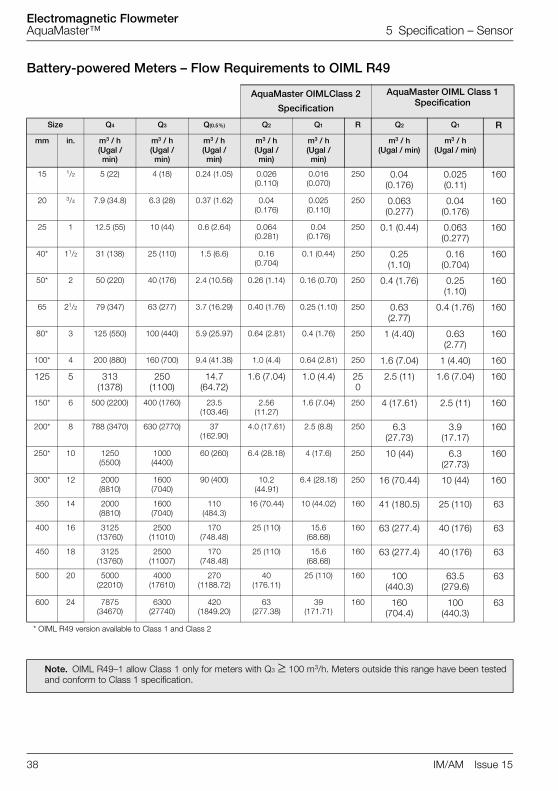
Battery-powered Meters – Flow Requirements to OIML R49
AquaMaster OIMLClass 2
Specification
AquaMaster OIML Class 1 Specification
Size Q4 Q3 Q(0.5%) Q2 Q1 R Q2 Q1 R
mm in. m3 / h (Ugal / min)
m3 / h (Ugal / min)
m3 / h (Ugal / min)
m3 / h (Ugal / min)
m3 / h (Ugal / min)
m3 / h (Ugal / min)
m3 / h (Ugal / min)
15 1/2 5 (22) 4 (18) 0.24 (1.05) 0.026 (0.110)
0.016 (0.070)
250 0.04 (0.176)
0.025 (0.11)
160
20 3/4 7.9 (34.8) 6.3 (28) 0.37 (1.62) 0.04 (0.176)
0.025 (0.110)
250 0.063 (0.277)
0.04 (0.176)
160
25 1 12.5 (55) 10 (44) 0.6 (2.64) 0.064 (0.281)
0.04 (0.176)
250 0.1 (0.44) 0.063 (0.277)
160
40* 11/2 31 (138) 25 (110) 1.5 (6.6) 0.16 (0.704)
0.1 (0.44) 250 0.25 (1.10)
0.16 (0.704)
160
50* 2 50 (220) 40 (176) 2.4 (10.56) 0.26 (1.14) 0.16 (0.70) 250 0.4 (1.76) 0.25 (1.10)
160
65 21/2 79 (347) 63 (277) 3.7 (16.29) 0.40 (1.76) 0.25 (1.10) 250 0.63 (2.77)
0.4 (1.76) 160
80* 3 125 (550) 100 (440) 5.9 (25.97) 0.64 (2.81) 0.4 (1.76) 250 1 (4.40) 0.63 (2.77)
160
100* 4 200 (880) 160 (700) 9.4 (41.38) 1.0 (4.4) 0.64 (2.81) 250 1.6 (7.04) 1 (4.40) 160
125 5 313 (1378)
250 (1100)
14.7 (64.72)
1.6 (7.04) 1.0 (4.4) 250
2.5 (11) 1.6 (7.04) 160
150* 6 500 (2200) 400 (1760) 23.5 (103.46)
2.56 (11.27)
1.6 (7.04) 250 4 (17.61) 2.5 (11) 160
200* 8 788 (3470) 630 (2770) 37 (162.90)
4.0 (17.61) 2.5 (8.8) 250 6.3 (27.73)
3.9 (17.17)
160
250* 10 1250 (5500)
1000 (4400)
60 (260) 6.4 (28.18) 4 (17.6) 250 10 (44) 6.3 (27.73)
160
300* 12 2000 (8810)
1600 (7040)
90 (400) 10.2 (44.91)
6.4 (28.18) 250 16 (70.44) 10 (44) 160
350 14 2000 (8810)
1600 (7040)
110 (484.3)
16 (70.44) 10 (44.02) 160 41 (180.5) 25 (110) 63
400 16 3125 (13760)
2500 (11010)
170 (748.48)
25 (110) 15.6 (68.68)
160 63 (277.4) 40 (176) 63
450 18 3125 (13760)
2500 (11007)
170 (748.48)
25 (110) 15.6 (68.68)
160 63 (277.4) 40 (176) 63
500 20 5000 (22010)
4000 (17610)
270 (1188.72)
40 (176.11)
25 (110) 160 100 (440.3)
63.5 (279.6)
63
600 24 7875 (34670)
6300 (27740)
420 (1849.20)
63 (277.38)
39 (171.71)
160 160 (704.4)
100 (440.3)
63
* OIML R49 version available to Class 1 and Class 2
Note. OIML R49–1 allow Class 1 only for meters with Q3 ≥ 100 m3/h. Meters outside this range have been testedand conform to Class 1 specification.

Electromagnetic FlowmeterAquaMaster™ 5 Specification – Sensor
IM/AM Issue 15 39
Wetted Materials
Screw-end metersBrass
Flanged metersElectrodes – stainless steel 316L
LiningSuitable for potable water (WRAS listed), ACS (except DN65)
Pressure limitationsAs flange rating
PN25 Max Process Temp 50 °C
PN40 Max Process Temp 40 °C
OIML / MID Approved Meters 16 bar
Pressure equipment directive 97/23/ECThis product is applicable in networks for the supply, distribution and discharge of water and associated equipment andis therefore exempt.
Conductivity>50 µS / cm
End Connections
Thread-end connections15 mm – G 3/4 in. B 3/4 in. NPSM
20 mm – G 1 in. B 1 in. NPSM
25 mm – G 11/4 in. B 11/4 in. NPSM
40 to 300 mm (1.5 to 12 in.) flangedEN1092-1 / ISO 7005 – PN10, PN16, PN25
ANSI B16.5 Class 150
AS 2129 Tables C, D, E and F
AS 4087 PN14, PN16, PN21
JIS to BS2210, 10k
350 to 600 mm (14 to 24 in.) flangedEN1092-1 / ISO 7005 – PN10, PN16, PN25
AS 4087 PN14, PN16, PN21
AS 2129 Tables C, D, E and F
ANSI B16.5 Class 150
JIS to B2210 5k and 10k
OIML R49 Approval
Size range and flow specificationSee specification table
Accuracy class1 and 2
Environmental classT50 0.1 °C to 50 °C (32.18 °F to 122 °F)

Electromagnetic FlowmeterAquaMaster™ 5 Specification – Sensor
40 IM/AM Issue 15
Pressure loss class< 0.63 bar
Minimum upstream pipe0 D
Minimum downstream pipe0 D
OrientationAny
MID ApprovalApproved to directive 2004/22/EC

Electromagnetic FlowmeterAquaMaster™ Specification – Transmitter
IM/AM Issue 15 41
Specification – Transmitter
AquaMaster Transmitter
MountingRemote or integral
Cable LengthRemote 200 m (650 ft)
HousingIP67 (NEMA 6P) Aluminum Alloy with Glass Window
Electrical connections20 mm glands (plastic or armored), or accepts 1/2 in. NPT threaded or military-style plug & socket
Sensor cableABB cable supplied as standard
Special cable available on application
SWA cable available on application
Power supplyBattery life @ 0 to 50 °C (32 to 122 °F)
Pulse and alarm outputsThree bidirectional solid state switches with common isolation ±35V DC 50mA
Serial data communications
1 battery – typically 1.2 years
2 batteries – typically 3 years
Type Voltage range (V) Absolute Rating Frequency (Hz) VA
AC 85 to 265 47 to 440 <10
Battery 3.6 (Lithium) – –
Output 1 Forward only, or forward plus reverse pulses
Output 2 Reverse pulses or direction indicator
Pulse output 50 Hz maximum, 50 % nominal duty cycle
Output 3 Alarm indicates any problem with the measurement or unit power
Local Port RS232 compatible via ABB lead (Option)
Remote Port (Option) RS232 with RI, RTS and CTS handshaking

Electromagnetic FlowmeterAquaMaster™ Specification – Transmitter
42 IM/AM Issue 15
Encoder Interface (non-logging versions only)
FunctionRemote reading of totalizer and serial no.
ProtocolABB encoder
Connections2-wire for inductive pads (max. cable length 80 m [260 ft])
3-wire for AMR
Compatible readersSevern Trent Services Smart reader
ABB or Elster SR100 and SR50
Logicon Versaprobe
Itron ERT
Compatible inductive padsStarpad
ABB
Telemetry applications using remote serial data communicationsInternal GSM modem Dual Band GSM; fully programmable schedule for battery operation and Automated MeterReading
Pressure System – External Transducer
Pressure range16 bar g or 16 bar Abs.
ConnectionStandard quick-fit male probe connector via an adapter cable
Operating temperature range–20 (ambient) to 70 °C (–4 to 158 °F)
Accuracy (typical)±0.4 % of range
Thermal error band (typically 100 °C [212 °F])±1.5 % span
Cable length5 or 10 m (16 or 33 ft)
Caution. Protect the sample and transducer from freezing.
Electromagnetic FlowmeterAquaMaster™ Specification – Transmitter
IM/AM Issue 15 43
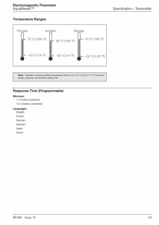
Temperature Ranges
Response Time (Programmable)
Minimum1 s (mains-powered)
15 s (battery-powered)
LanguagesEnglish
French
German
Spanish
Italian
Dutch
Note. Operation outside ambient temperature limits of 0 to 45 °C (32 to 113 °F) reduces battery capacity and shortens battery life.
��7�8
9 #':�';9��':�<
�#':�';��5':�<
9�#':�';9�':�<
�#':�';��#':�<
�)=(6�
�#':�';��5':�<
�71��
9�#':�';��':�<

Electromagnetic FlowmeterAquaMaster™ Specification – Transmitter
44 IM/AM Issue 15
Mounting
Pipe Conditions
Pressure Loss
Flow Rate Pressure Loss in bar (psi)
Q3 <0.63 (9.1)
Q3/2 <0.16 (2.3)
Sensor Electrodes
45 ° Maximum
Flow Direction
0 x pipe dia. 0 x pipe dia.
minimumminimum

Electromagnetic FlowmeterAquaMaster™ Specification – Transmitter
IM/AM Issue 15 45
Logger details (option)
GSM Antenna (option)
MountingIntegral with transmitter or remote.
Antenna environmentalIP66 (NEMA4) waterproof for accidental submersion
(Note. The GSM does not operate with integral antenna under water).
General advice is to mount the antenna as high as possible, always outside of any metal enclosure and not under thesurface of the ground.
Logger
1 2 3
Logger Function Flow & Pressure Flow & PressureForward,
Reverse, Tariffs & Net Flow Totals
No. of Records 8831 11361 366
Logging Interval 15 to 65500 s (adjustable) 24 hr (fixed)
Typical Capacity 3 months@15 min
~7 days @ 1 min 1 year
Mode Cyclic Cyclic Cyclic
Use ABB LogMaster
Use Technolog (PMAC)
Use Primayer Primeware
Use OSI PI Database / CBV (WADIS) System

Electromagnetic FlowmeterAquaMaster™ Specification – Transmitter
46 IM/AM Issue 15
Default Settings Table
Configuration Parameter Default European Default North American
Pulse Factor 1 1
Pulse Units m3 Ugal
Totalizer Units m3 Ugal
Full Scale Flow Q3 Q3
Flow Units m3 / h MUGD
Velocity Units m / s ft / s
Date Format from Country Code DDMMYY MMDDYY
Flow Response Time (s) 3 3
Display Flow Rate Yes Yes
Display Forward Total Yes Yes
Display Reverse Total Yes Yes
Display Net Total No No
Display Date No No
Display Velocity No No
Output Option Pulse Forward Pulses Forward Pulses Forward
Output Option Pulse Reverse Pulses Reverse Pulses Reverse
Profile Factor 1 1
Probe Insertion Factor 1 1
Electromagnetic FlowmeterAquaMaster™ Specification – Transmitter
IM/AM Issue 15 47
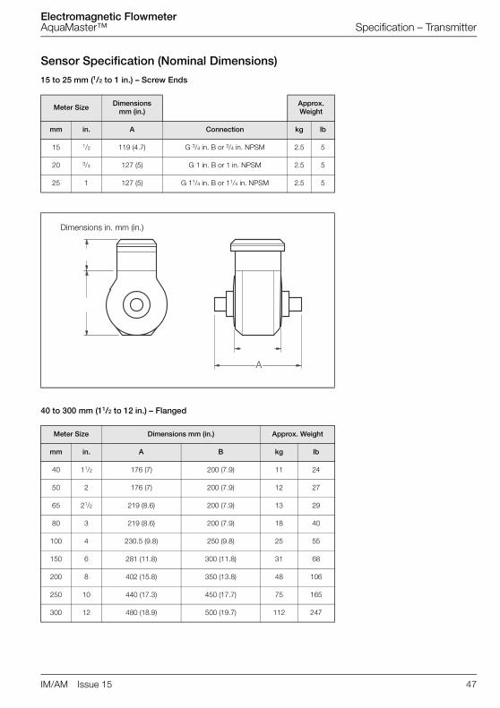
Sensor Specification (Nominal Dimensions)
15 to 25 mm (1/2 to 1 in.) – Screw Ends
40 to 300 mm (11/2 to 12 in.) – Flanged
Meter Size Dimensionsmm (in.)
Approx. Weight
mm in. A Connection kg lb
15 1/2 119 (4.7) G 3/4 in. B or 3/4 in. NPSM 2.5 5
20 3/4 127 (5) G 1 in. B or 1 in. NPSM 2.5 5
25 1 127 (5) G 11/4 in. B or 11/4 in. NPSM 2.5 5
Dimensions in. mm (in.)
Meter Size Dimensions mm (in.) Approx. Weight
mm in. A B kg lb
40 11/2 176 (7) 200 (7.9) 11 24
50 2 176 (7) 200 (7.9) 12 27
65 21/2 219 (8.6) 200 (7.9) 13 29
80 3 219 (8.6) 200 (7.9) 18 40
100 4 230.5 (9.8) 250 (9.8) 25 55
150 6 281 (11.8) 300 (11.8) 31 68
200 8 402 (15.8) 350 (13.8) 48 106
250 10 440 (17.3) 450 (17.7) 75 165
300 12 480 (18.9) 500 (19.7) 112 247
�

Electromagnetic FlowmeterAquaMaster™ Specification – Transmitter
48 IM/AM Issue 15
350 to 600 mm (14 to 24 in.) – Flanged
DS/AMAS Issue 6 (AquaMaster)
Meter Size Dimensions mm (in.) Approx. Weight
mm in.. A B C kg lb
350 14 513 (20.2) 520 (20.5) 550 (21.7) 100 220
400 16 570 (22.4) 576 (22.7) 600 (23.6) 115 253
450 18 632 (24.9) 627 (24.7) 698 (27.5) 160 352
500 20 686 (27.0) 679 (26.7) 768 (30.2) 217 455
600 24 772 (30.4) 770 (30.3) 918 (36.1) 315 693
BA
>�#'?�
��
�

Electromagnetic FlowmeterAquaMaster™ Appendix A Hazardous Area Protection
IM/AM Issue 15 49
Appendix A Hazardous Area Protection
A.1 GSM-Equipped Units – Safety PrecautionsThe following safety precautions must be observed during all phases of the operation, usage, service orrepair of this GSM cellular terminal. Failure to comply with these precautions violates safety standards ofdesign, manufacture and intended use of the product. The Company assumes no liability for customerfailure to comply with these precautions.
1. When in a hospital or other health care facility, observe the restrictions on the use of mobiles. Switchthe cellular terminal or mobile off, if instructed to do so by the guidelines posted in sensitive areas.Medical equipment may be sensitive to RF energy. The operation of cardiac pacemakers, otherimplanted medical equipment and hearing aids can be affected by interference from cellular terminalsor mobiles placed close to the device. If in doubt about potential danger, contact the physician or themanufacturer of the device to verify that the equipment is properly shielded. Pacemaker patients areadvised to keep their hand-held mobile away from the pacemaker, while it is on.
2. Switch off the cellular terminal or mobile before boarding an aircraft. Make sure it cannot be switchedon inadvertently. The operation of wireless appliances in an aircraft is forbidden to preventinterference with communications systems. Failure to observe these instructions may lead to thesuspension or denial of cellular services to the offender, legal action, or both.
3. Do not operate the cellular terminal or mobile in the presence of flammable gases or fumes. Switchoff the cellular terminal when you are near petrol stations, fuel depots, chemical plants or whereblasting operations are in progress. Operation of any electrical equipment in potentially explosiveatmospheres can constitute a safety hazard.
4. Your cellular terminal or mobile receives and transmits radio frequency energy while switched on.Remember that interference can occur if it is used close to TV sets, radios, computers orinadequately shielded equipment. Follow any special regulations and always switch off the cellularterminal or mobile wherever forbidden, or when you suspect that it may cause interference ordanger.
Remember, in order to make or receive calls, the cellular terminal or mobile must be switched on and in aservice area with adequate cellular signal strength.
Note. Cellular terminals or mobiles operate using radio signals and cellular networks cannot be guaranteed to connect in all conditions. Therefore, you should never rely solely upon any wireless device for essential communications, for example emergency calls.

Electromagnetic FlowmeterAquaMaster™ Appendix A Hazardous Area Protection
50 IM/AM Issue 15
Fig.
A.1
Aqu
aMas
ter
Blo
ck D
iagr
am
� � � � � �
� � � � � �
Mea
sure
men
t
Sys
tem
Pre
ssur
eTr
ansd
ucer
Pro
cess
or
Dis
play
Par
t No.
WEB
C20
00
Loca
l Con
figur
atio
n A
dapt
or
Com
mon
Pul
se/A
larm
C
ircui
ts
Opt
iona
l RS
232
Com
mun
icat
ion
Por
t
Opt
iona
lG
SM
Mod
em
Tran
smitt
er
Sen
sor
Opt
iona
lP
ower
Sup
ply *
*

Electromagnetic FlowmeterAquaMaster™ Notes
IM/AM Issue 15 51
Notes

Electromagnetic FlowmeterAquaMaster™ Notes
52 IM/AM Issue 15

PRODUCTS & CUSTOMER SUPPORTProducts
Automation Systems• for the following industries:
– Chemical & Pharmaceutical– Food & Beverage– Manufacturing– Metals and Minerals– Oil, Gas & Petrochemical– Pulp and Paper
Drives and Motors• AC and DC Drives, AC and DC Machines, AC
Motors to 1kV• Drive Systems• Force Measurement• Servo Drives
Controllers & Recorders• Single and Multi-loop Controllers• Circular Chart and Strip Chart Recorders• Paperless Recorders• Process Indicators
Flexible Automation• Industrial Robots and Robot Systems
Flow Measurement• Electromagnetic Flowmeters• Mass Flowmeters• Turbine Flowmeters• Wedge Flow Elements
Marine Systems & Turbochargers• Electrical Systems• Marine Equipment• Offshore Retrofit and Refurbishment
Process Analytics• Process Gas Analysis• Systems Integration
Transmitters• Pressure• Temperature• Level• Interface Modules
Valves, Actuators and Positioners• Control Valves• Actuators• Positioners
Water, Gas & Industrial Analytics Instrumentation
• pH, Conductivity and Dissolved Oxygen Transmitters and Sensors
• Ammonia, Nitrate, Phosphate, Silica, Sodium, Chloride, Fluoride, Dissolved Oxygen and Hydrazine Analyzers
• Zirconia Oxygen Analyzers, Katharometers, Hydrogen Purity and Purge-gas Monitors, Thermal Conductivity
Customer Support
We provide a comprehensive after sales service via aWorldwide Service Organization. Contact one of thefollowing offices for details on your nearest Service andRepair Centre.
United KingdomABB LimitedTel: +44 (0)1453 826661Fax: +44 (0)1453 829671
United States of AmericaABB Inc.Tel: +1 215 674 6000Fax: +1 215 674 7183
Client WarrantyPrior to installation, the equipment referred to in thismanual must be stored in a clean, dry environment, inaccordance with the Company's publishedspecification.
Periodic checks must be made on the equipment'scondition. In the event of a failure under warranty, thefollowing documentation must be provided assubstantiation:
1. A listing evidencing process operation and alarm logs at time of failure.
2. Copies of all storage, installation, operating and maintenance records relating to the alleged faulty unit.

IM/A
MIs
sue
15
ABB has Sales & Customer Support expertisein over 100 countries worldwide
www.abb.com
The Company’s policy is one of continuous product improvement and the right is reserved to modify the
information contained herein without notice.
Printed in UK (05.10)
© ABB 2010
ABB LimitedOldends Lane, StonehouseGloucestershireGL10 3TAUKTel: +44 (0)1453 826661Fax: +44 (0)1453 829671
ABB Inc.125 E. County Line RoadWarminsterPA 18974USATel:+1 215 674 6000Fax:+1 215 674 7183
![User's AXF Manual Magnetic Flowmeter Integral Flowmeter ... · User's Manual Yo kogawa Electric Corporation AXF Magnetic Flowmeter Integral Flowmeter/ Remote Flowtube [Hardware Edition]](https://img.pdfslide.net/doc/110x75/5c40f15893f3c338c3289cbb/users-axf-manual-magnetic-flowmeter-integral-flowmeter-users-manual-yo.jpg)