Embed Size (px)
Citation preview

1 1
1 1
INSTRUCTION MANUALFOR INLINE REFRACTOMETER
PR-03
WARNING
The process medium may be hot or otherwise hazardous.
Precautions when removing the sensor from the process line:Make positively sure that the process line is not under pressure. Open a vent valve to the atmosphere.For a prism wash system, close a hand valve for the wash medium and disable the wash valve.Loosen the clamp cautiously, be prepared to tighten again.Be out of the way of any possible splash and ensure the possibility of escape.Use shields and protective clothing adequate for the process medium.Do not rely on avoidance of contact with the process medium.After removal of the sensor, it may be necessary to mount a blind cover for security reasons.
Document/Revision No. INM-3: Rev. 2/4 Effective: February 15th, 2005
This product manual is delivered to the end user with a K-Patents product.Information in this manual is subject to change without notice. When the manual is changed,a revised copy is made available at http://www.kpatents.com/.Feedback on this manual can be sent by email to [email protected].
THE PASSWORD FOR PR-03 IS 7 8 4 5 1 2 IN PROGRAM VERSIONS 4.0 AND HIGHER.
K-PATENTS OYPostal address:P.O. Box 77FIN-01511 Vantaa, FinlandTel. + 358-9-825 6640Fax +358-9-8256 [email protected]
K-PATENTS OYStreet address:Elannontie 5FIN-01510 Vantaa, Finland
K-PATENTS, INC.1804 Centre Point Circle,Suite 106,Naperville, IL 60563Tel. +1-630-955 1545Fax +1-630-955 [email protected]
Protected by one or more ofthe following U.S. patents:Patent No. 4,571,075Patent No. 5,563,737Patent No. 5,009,113Patent No. 5,617,201Patent No. 5,309,288Patent No. 6,067,151

2 2
2 2
3 3
3 3
Table of contents
1 Introduction . . . . . . . . . . . . . . . . . . . . . . . . . . . . . . . . . . . . . . . . . . . . . . . . . . . . . . . . . . . . . . . . . . 11.1 PR-03 refractometer models . . . . . . . . . . . . . . . . . . . . . . . . . . . . . . . . . . . . . . . . . . . . . . . 11.2 Principle of measurement . . . . . . . . . . . . . . . . . . . . . . . . . . . . . . . . . . . . . . . . . . . . . . . . . . 21.3 General safety considerations . . . . . . . . . . . . . . . . . . . . . . . . . . . . . . . . . . . . . . . . . . . . . . 31.4 Warranty . . . . . . . . . . . . . . . . . . . . . . . . . . . . . . . . . . . . . . . . . . . . . . . . . . . . . . . . . . . . . . . 31.5 Disposal . . . . . . . . . . . . . . . . . . . . . . . . . . . . . . . . . . . . . . . . . . . . . . . . . . . . . . . . . . . . . . . . 3
2 Inline refractometer sensor . . . . . . . . . . . . . . . . . . . . . . . . . . . . . . . . . . . . . . . . . . . . . . . . . . . . 52.1 Sensor description . . . . . . . . . . . . . . . . . . . . . . . . . . . . . . . . . . . . . . . . . . . . . . . . . . . . . . . . 52.2 Mounting the sensor . . . . . . . . . . . . . . . . . . . . . . . . . . . . . . . . . . . . . . . . . . . . . . . . . . . . . . 62.2.1 Choosing sensor mounting location . . . . . . . . . . . . . . . . . . . . . . . . . . . . . . . . . . . . . . . . . 62.2.2 Check list for pipe mounting (PR-03-A, PR-03-D, PR-03-M) . . . . . . . . . . . . . . . . . . . . . 72.2.3 Check list for mounting in a tank, a vessel or a large pipe (PR-03-P) . . . . . . . . . . . . . . . 8
3 Indicating transmitter (IT-R) . . . . . . . . . . . . . . . . . . . . . . . . . . . . . . . . . . . . . . . . . . . . . . . . . . . 93.1 Indicating transmitter description . . . . . . . . . . . . . . . . . . . . . . . . . . . . . . . . . . . . . . . . . . 93.2 Mounting Indicating transmitter . . . . . . . . . . . . . . . . . . . . . . . . . . . . . . . . . . . . . . . . . . . 103.2.1 Mounting the Interconnecting cable . . . . . . . . . . . . . . . . . . . . . . . . . . . . . . . . . . . . . . . . 103.2.2 Electrical connections . . . . . . . . . . . . . . . . . . . . . . . . . . . . . . . . . . . . . . . . . . . . . . . . . . . 113.2.2.1 Connecting with sensor . . . . . . . . . . . . . . . . . . . . . . . . . . . . . . . . . . . . . . . . . . . . . . . . 123.2.2.2 AC power connection . . . . . . . . . . . . . . . . . . . . . . . . . . . . . . . . . . . . . . . . . . . . . . . . . 123.2.2.3 +24 V DC power connection . . . . . . . . . . . . . . . . . . . . . . . . . . . . . . . . . . . . . . . . . . . . 123.2.2.4 Current output connection . . . . . . . . . . . . . . . . . . . . . . . . . . . . . . . . . . . . . . . . . . . . . 133.2.2.5 Serial bus connections . . . . . . . . . . . . . . . . . . . . . . . . . . . . . . . . . . . . . . . . . . . . . . . . 133.2.2.6 Input switch connections . . . . . . . . . . . . . . . . . . . . . . . . . . . . . . . . . . . . . . . . . . . . . . . 133.2.3 Serial output connections: connecting a computer with the IT-R . . . . . . . . . . . . . . . . . 143.2.4 Demo mode connection . . . . . . . . . . . . . . . . . . . . . . . . . . . . . . . . . . . . . . . . . . . . . . . . . 153.3 Cable signals between IT-R and sensor . . . . . . . . . . . . . . . . . . . . . . . . . . . . . . . . . . . . . . 16
4 Accessory units . . . . . . . . . . . . . . . . . . . . . . . . . . . . . . . . . . . . . . . . . . . . . . . . . . . . . . . . . . . . . 174.1 Separate relay units . . . . . . . . . . . . . . . . . . . . . . . . . . . . . . . . . . . . . . . . . . . . . . . . . . . . . . 174.1.1 Relay unit description . . . . . . . . . . . . . . . . . . . . . . . . . . . . . . . . . . . . . . . . . . . . . . . . . . . 174.1.1.1 Relay unit PR-7080 . . . . . . . . . . . . . . . . . . . . . . . . . . . . . . . . . . . . . . . . . . . . . . . . . . . 184.1.1.2 Relay unit -WR . . . . . . . . . . . . . . . . . . . . . . . . . . . . . . . . . . . . . . . . . . . . . . . . . . . . . . 184.1.2 Prism wash system description . . . . . . . . . . . . . . . . . . . . . . . . . . . . . . . . . . . . . . . . . . . . 184.1.3 Relay unit mounting and connections . . . . . . . . . . . . . . . . . . . . . . . . . . . . . . . . . . . . . . . 184.1.3.1 Mounting and connecting Relay unit PR-7080 . . . . . . . . . . . . . . . . . . . . . . . . . . . . . . 184.1.3.2 Mounting and connecting Relay unit -WR . . . . . . . . . . . . . . . . . . . . . . . . . . . . . . . . . 204.1.4 Mounting and connecting prism wash systems . . . . . . . . . . . . . . . . . . . . . . . . . . . . . . . . 204.1.4.1 Recommended wash pressures and times . . . . . . . . . . . . . . . . . . . . . . . . . . . . . . . . . . 204.1.4.2 Prism wash nozzles . . . . . . . . . . . . . . . . . . . . . . . . . . . . . . . . . . . . . . . . . . . . . . . . . . . 204.1.4.3 Mounting of prism wash systems with steam and water . . . . . . . . . . . . . . . . . . . . . . . 234.1.4.4 Mounting of prism wash systems with high pressure water . . . . . . . . . . . . . . . . . . . . 254.2 External output unit PR-7090 . . . . . . . . . . . . . . . . . . . . . . . . . . . . . . . . . . . . . . . . . . . . . 264.2.1 Description . . . . . . . . . . . . . . . . . . . . . . . . . . . . . . . . . . . . . . . . . . . . . . . . . . . . . . . . . . . 264.2.2 External output unit mounting and connections . . . . . . . . . . . . . . . . . . . . . . . . . . . . . . . 26

4 4
4 4
5 Startup, configuration and calibration adjustment . . . . . . . . . . . . . . . . . . . . . . . . . . . . . . 295.1 Startup . . . . . . . . . . . . . . . . . . . . . . . . . . . . . . . . . . . . . . . . . . . . . . . . . . . . . . . . . . . . . . . . 295.2 System check . . . . . . . . . . . . . . . . . . . . . . . . . . . . . . . . . . . . . . . . . . . . . . . . . . . . . . . . . . . 295.2.1 Checking accessory units . . . . . . . . . . . . . . . . . . . . . . . . . . . . . . . . . . . . . . . . . . . . . . . . 305.2.2 Testing prism wash . . . . . . . . . . . . . . . . . . . . . . . . . . . . . . . . . . . . . . . . . . . . . . . . . . . . . 305.3 Using Indicating transmitter . . . . . . . . . . . . . . . . . . . . . . . . . . . . . . . . . . . . . . . . . . . . . . 315.3.1 Keyboard functions . . . . . . . . . . . . . . . . . . . . . . . . . . . . . . . . . . . . . . . . . . . . . . . . . . . . . 315.4 Soft key Display: Getting information on the process
and the settings . . . . . . . . . . . . . . . . . . . . . . . . . . . . . . . . . . . . . . . . . . . . . . . . . . . . . . . . . 325.4.1 Viewing the Optical image . . . . . . . . . . . . . . . . . . . . . . . . . . . . . . . . . . . . . . . . . . . . . . . 335.4.2 Viewing System configuration . . . . . . . . . . . . . . . . . . . . . . . . . . . . . . . . . . . . . . . . . . . . 335.4.3 Checking conditions inside sensor head . . . . . . . . . . . . . . . . . . . . . . . . . . . . . . . . . . . . . 335.5 Soft key Calibrate: Viewing and changing system settings . . . . . . . . . . . . . . . . . . . 345.5.1 Viewing Optical image and raw data . . . . . . . . . . . . . . . . . . . . . . . . . . . . . . . . . . . . . . . 345.5.2 Raw data explanations . . . . . . . . . . . . . . . . . . . . . . . . . . . . . . . . . . . . . . . . . . . . . . . . . . . 345.5.3 Viewing Scaled image . . . . . . . . . . . . . . . . . . . . . . . . . . . . . . . . . . . . . . . . . . . . . . . . . . . 355.5.4 Viewing slope . . . . . . . . . . . . . . . . . . . . . . . . . . . . . . . . . . . . . . . . . . . . . . . . . . . . . . . . . 355.5.5 Viewing Image diagnostics . . . . . . . . . . . . . . . . . . . . . . . . . . . . . . . . . . . . . . . . . . . . . . . 365.6 Configuring input switches . . . . . . . . . . . . . . . . . . . . . . . . . . . . . . . . . . . . . . . . . . . . . . . . 365.7 Configuring relays . . . . . . . . . . . . . . . . . . . . . . . . . . . . . . . . . . . . . . . . . . . . . . . . . . . . . . . 375.8 Configuring external output unit . . . . . . . . . . . . . . . . . . . . . . . . . . . . . . . . . . . . . . . . . . . 395.9 Configuring automatic prism wash . . . . . . . . . . . . . . . . . . . . . . . . . . . . . . . . . . . . . . . . . 395.9.1 Timed wash . . . . . . . . . . . . . . . . . . . . . . . . . . . . . . . . . . . . . . . . . . . . . . . . . . . . . . . . . . . 405.9.2 Smart wash . . . . . . . . . . . . . . . . . . . . . . . . . . . . . . . . . . . . . . . . . . . . . . . . . . . . . . . . . . . 405.9.3 Preventing automatic wash . . . . . . . . . . . . . . . . . . . . . . . . . . . . . . . . . . . . . . . . . . . . . . . 415.9.4 Prism wash check . . . . . . . . . . . . . . . . . . . . . . . . . . . . . . . . . . . . . . . . . . . . . . . . . . . . . . 415.10 Adjusting concentration calibration . . . . . . . . . . . . . . . . . . . . . . . . . . . . . . . . . . . . . . . . 435.10.1 Checking current calibration . . . . . . . . . . . . . . . . . . . . . . . . . . . . . . . . . . . . . . . . . . . . . . 435.10.2 Concentration calibration from keyboard . . . . . . . . . . . . . . . . . . . . . . . . . . . . . . . . . . . . 435.10.3 Output current range selection . . . . . . . . . . . . . . . . . . . . . . . . . . . . . . . . . . . . . . . . . . . . 445.10.4 Temperature calibration . . . . . . . . . . . . . . . . . . . . . . . . . . . . . . . . . . . . . . . . . . . . . . . . . 445.10.5 Adjusting damping time . . . . . . . . . . . . . . . . . . . . . . . . . . . . . . . . . . . . . . . . . . . . . . . . . 445.10.6 Field calibration . . . . . . . . . . . . . . . . . . . . . . . . . . . . . . . . . . . . . . . . . . . . . . . . . . . . . . . 455.10.7 Bench calibration . . . . . . . . . . . . . . . . . . . . . . . . . . . . . . . . . . . . . . . . . . . . . . . . . . . . . . 46
6 Regular maintenance . . . . . . . . . . . . . . . . . . . . . . . . . . . . . . . . . . . . . . . . . . . . . . . . . . . . . . . . 476.1 Checking the sensor moisture . . . . . . . . . . . . . . . . . . . . . . . . . . . . . . . . . . . . . . . . . . . . . 476.2 Checking and replacing prism or prism gaskets . . . . . . . . . . . . . . . . . . . . . . . . . . . . . . 476.3 Disassembling and assembling a standard length sensor . . . . . . . . . . . . . . . . . . . . . . . 486.3.1 Disassembling the sensor . . . . . . . . . . . . . . . . . . . . . . . . . . . . . . . . . . . . . . . . . . . . . . . . 486.3.2 Replacing the prism and prism gaskets . . . . . . . . . . . . . . . . . . . . . . . . . . . . . . . . . . . . . . 496.3.3 Assembling the sensor . . . . . . . . . . . . . . . . . . . . . . . . . . . . . . . . . . . . . . . . . . . . . . . . . . 506.4 Disassembling and assembling a probe sensor . . . . . . . . . . . . . . . . . . . . . . . . . . . . . . . . 516.4.1 Disassembling the probe sensor . . . . . . . . . . . . . . . . . . . . . . . . . . . . . . . . . . . . . . . . . . . 516.4.2 Replacing the prism and prism gaskets . . . . . . . . . . . . . . . . . . . . . . . . . . . . . . . . . . . . . . 526.4.3 Assembling the probe sensor . . . . . . . . . . . . . . . . . . . . . . . . . . . . . . . . . . . . . . . . . . . . . 54

5 5
5 5
7 Troubleshooting and correcting problems . . . . . . . . . . . . . . . . . . . . . . . . . . . . . . . . . . . . . 557.1 Troubleshooting Indicating transmitter . . . . . . . . . . . . . . . . . . . . . . . . . . . . . . . . . . . . . 557.2 Troubleshooting sensor . . . . . . . . . . . . . . . . . . . . . . . . . . . . . . . . . . . . . . . . . . . . . . . . . . . 557.2.1 LED value . . . . . . . . . . . . . . . . . . . . . . . . . . . . . . . . . . . . . . . . . . . . . . . . . . . . . . . . . . . . 557.2.2 Sensor temperature and humidity . . . . . . . . . . . . . . . . . . . . . . . . . . . . . . . . . . . . . . . . . . 567.2.3 Slope value . . . . . . . . . . . . . . . . . . . . . . . . . . . . . . . . . . . . . . . . . . . . . . . . . . . . . . . . . . . 567.2.4 Image diagnostics . . . . . . . . . . . . . . . . . . . . . . . . . . . . . . . . . . . . . . . . . . . . . . . . . . . . . . 57
8 Sensor specifications andother sensor information . . . . . . . . . . . . . . . . . . . . . . . . . . . . . . . . . . . . . . . . . . . . . . . . . . . . . 598.1 Sensor labels . . . . . . . . . . . . . . . . . . . . . . . . . . . . . . . . . . . . . . . . . . . . . . . . . . . . . . . . . . . 598.2 Sensor compatibility . . . . . . . . . . . . . . . . . . . . . . . . . . . . . . . . . . . . . . . . . . . . . . . . . . . . . 598.3 Sanitary refractometer PR-03-A . . . . . . . . . . . . . . . . . . . . . . . . . . . . . . . . . . . . . . . . . . . 598.3.1 PR-03-A sensor model code . . . . . . . . . . . . . . . . . . . . . . . . . . . . . . . . . . . . . . . . . . . . . . 608.3.2 PR-03-A mounting hardware model code . . . . . . . . . . . . . . . . . . . . . . . . . . . . . . . . . . . . 608.3.3 PR-03-A specifications . . . . . . . . . . . . . . . . . . . . . . . . . . . . . . . . . . . . . . . . . . . . . . . . . . 628.3.4 PR-03-A parts lists . . . . . . . . . . . . . . . . . . . . . . . . . . . . . . . . . . . . . . . . . . . . . . . . . . . . . 638.3.5 PR-03-A mounting specifics . . . . . . . . . . . . . . . . . . . . . . . . . . . . . . . . . . . . . . . . . . . . . . 658.4 Probe refractometer PR-03-P . . . . . . . . . . . . . . . . . . . . . . . . . . . . . . . . . . . . . . . . . . . . . 688.4.1 PR-03-P sensor model code . . . . . . . . . . . . . . . . . . . . . . . . . . . . . . . . . . . . . . . . . . . . . . 688.4.2 PR-03-P mounting hardware model code . . . . . . . . . . . . . . . . . . . . . . . . . . . . . . . . . . . . 688.4.3 PR-03-P specifications . . . . . . . . . . . . . . . . . . . . . . . . . . . . . . . . . . . . . . . . . . . . . . . . . . 698.4.4 PR-03-P parts lists . . . . . . . . . . . . . . . . . . . . . . . . . . . . . . . . . . . . . . . . . . . . . . . . . . . . . . 708.4.5 PR-03-P mounting specifics . . . . . . . . . . . . . . . . . . . . . . . . . . . . . . . . . . . . . . . . . . . . . . 728.4.6 PR-03-P programming specifics . . . . . . . . . . . . . . . . . . . . . . . . . . . . . . . . . . . . . . . . . . . 748.5 Compact process refractometer PR-03-D . . . . . . . . . . . . . . . . . . . . . . . . . . . . . . . . . . . . 758.5.1 PR-03-D sensor model code . . . . . . . . . . . . . . . . . . . . . . . . . . . . . . . . . . . . . . . . . . . . . . 758.5.2 PR-03-D mounting hardware model code . . . . . . . . . . . . . . . . . . . . . . . . . . . . . . . . . . . . 758.5.3 PR-03-D specifications . . . . . . . . . . . . . . . . . . . . . . . . . . . . . . . . . . . . . . . . . . . . . . . . . . 768.5.4 PR-03-D parts lists . . . . . . . . . . . . . . . . . . . . . . . . . . . . . . . . . . . . . . . . . . . . . . . . . . . . . 778.5.5 PR-03-D mounting specifics . . . . . . . . . . . . . . . . . . . . . . . . . . . . . . . . . . . . . . . . . . . . . . 798.6 Process refractometer PR-03-M . . . . . . . . . . . . . . . . . . . . . . . . . . . . . . . . . . . . . . . . . . . 818.6.1 PR-03-M sensor model code . . . . . . . . . . . . . . . . . . . . . . . . . . . . . . . . . . . . . . . . . . . . . . 818.6.2 PR-03-M specifications . . . . . . . . . . . . . . . . . . . . . . . . . . . . . . . . . . . . . . . . . . . . . . . . . . 828.6.3 PR-03-M parts lists . . . . . . . . . . . . . . . . . . . . . . . . . . . . . . . . . . . . . . . . . . . . . . . . . . . . . 838.6.4 PR-03-M mounting specifics . . . . . . . . . . . . . . . . . . . . . . . . . . . . . . . . . . . . . . . . . . . . . . 858.7 Valve body refractometer PR-03-W . . . . . . . . . . . . . . . . . . . . . . . . . . . . . . . . . . . . . . . . . 858.7.1 PR-03-W sensor model code . . . . . . . . . . . . . . . . . . . . . . . . . . . . . . . . . . . . . . . . . . . . . . 868.7.2 PR-03-W specifications . . . . . . . . . . . . . . . . . . . . . . . . . . . . . . . . . . . . . . . . . . . . . . . . . . 878.7.3 PR-03-W parts lists . . . . . . . . . . . . . . . . . . . . . . . . . . . . . . . . . . . . . . . . . . . . . . . . . . . . . 888.7.4 PR-03-W mounting specifics . . . . . . . . . . . . . . . . . . . . . . . . . . . . . . . . . . . . . . . . . . . . . . 89

6 6
6 6
9 Indicating transmitter specifications . . . . . . . . . . . . . . . . . . . . . . . . . . . . . . . . . . . . . . . . . . 919.1 IT-R label . . . . . . . . . . . . . . . . . . . . . . . . . . . . . . . . . . . . . . . . . . . . . . . . . . . . . . . . . . . . . . 919.2 IT-R compatibility . . . . . . . . . . . . . . . . . . . . . . . . . . . . . . . . . . . . . . . . . . . . . . . . . . . . . . . 919.2.1 Upgrading IT-R program version . . . . . . . . . . . . . . . . . . . . . . . . . . . . . . . . . . . . . . . . . . 919.3 Model code . . . . . . . . . . . . . . . . . . . . . . . . . . . . . . . . . . . . . . . . . . . . . . . . . . . . . . . . . . . . . 929.3.1 IT-R model code . . . . . . . . . . . . . . . . . . . . . . . . . . . . . . . . . . . . . . . . . . . . . . . . . . . . . . . 929.3.2 Interconnecting cable model code . . . . . . . . . . . . . . . . . . . . . . . . . . . . . . . . . . . . . . . . . 939.4 IT-R Specifications . . . . . . . . . . . . . . . . . . . . . . . . . . . . . . . . . . . . . . . . . . . . . . . . . . . . . . 939.4.1 Fuses . . . . . . . . . . . . . . . . . . . . . . . . . . . . . . . . . . . . . . . . . . . . . . . . . . . . . . . . . . . . . . . . 939.4.2 Serial output specifications . . . . . . . . . . . . . . . . . . . . . . . . . . . . . . . . . . . . . . . . . . . . . . . 949.4.3 Password . . . . . . . . . . . . . . . . . . . . . . . . . . . . . . . . . . . . . . . . . . . . . . . . . . . . . . . . . . . . . 949.5 IT-R Parts list . . . . . . . . . . . . . . . . . . . . . . . . . . . . . . . . . . . . . . . . . . . . . . . . . . . . . . . . . . 959.6 Command selection tree . . . . . . . . . . . . . . . . . . . . . . . . . . . . . . . . . . . . . . . . . . . . . . . . . . 969.7 Display messages . . . . . . . . . . . . . . . . . . . . . . . . . . . . . . . . . . . . . . . . . . . . . . . . . . . . . . . . 97
10 PR-03 process refractometers in potentially explosive atmosphere . . . . . . . . . . . . . 10110.1 Equipment . . . . . . . . . . . . . . . . . . . . . . . . . . . . . . . . . . . . . . . . . . . . . . . . . . . . . . . . . . . . 10110.2 Installation . . . . . . . . . . . . . . . . . . . . . . . . . . . . . . . . . . . . . . . . . . . . . . . . . . . . . . . . . . . . 10210.3 PR-03-...-AX parts list: differences to standard sensors . . . . . . . . . . . . . . . . . . . . . . . 103
A Glossary and Abbreviations . . . . . . . . . . . . . . . . . . . . . . . . . . . . . . . . . . . . . . . . . . . . . . . . . 105
B Information about Delivery data sheet (DDS) . . . . . . . . . . . . . . . . . . . . . . . . . . . . . . . . . . 107
C K-Patents inline refractometer calibration data report . . . . . . . . . . . . . . . . . . . . . . . . . 109
D Instrument verification ISO 9000 . . . . . . . . . . . . . . . . . . . . . . . . . . . . . . . . . . . . . . . . . . . . . 111
Index . . . . . . . . . . . . . . . . . . . . . . . . . . . . . . . . . . . . . . . . . . . . . . . . . . . . . . . . . . . . . . . . . . . . . . . . . . 115

7 7
7 7
1 Introduction 1
1 Introduction
The K-Patents inline refractometer is an instrument for measuring liquid concentration in the process line.The measurement is based on the refraction of light in the process medium, an accurate and safe way ofmeasuring liquid concentration.
The refractometer sensor (A in figure Figure 1.1), mounted inline, sends a ray of light into the processmedium and measures the angle in which the light is refracted back from the liquid. This information isthen sent via the interconnecting cable (B) to the Indicating transmitter (C). The Indicating transmitter (IT-R) then calculates the concentration of the process liquid based on the refractive angle, taking temperatureand pre-defined process conditions into account. The output the IT-R provides is a 4 to 20 mA DC outputsignal proportional to process solution concentration, but a serial output is also available as a standard.
C: Indicating Transmitter
A B C D
7
4
1
0
8
5
2
.
9
6
3
- ENTER RESET
K-PATENTSPROCESS INSTRUMENTS
B: Interconnecting cableA: Sensor
Figure 1.1 Refractometer equipment.
1.1 PR-03 refractometer models
The basic system of a sensor and an Indicating transmitter connected with a cable is the same in all PR-03Inline refractometer models. However, there are different sensor models, each adapted for different processrequirements.
The Sanitary refractometer sensor PR-03-A and the Probe refractometer sensor PR-03-P both meetthe 3-A Sanitary Standard requirements. The model PR-03-A is an all-purpose instrument for a variety ofalimentary processes while the PR-03-P is especially designed for cookers and tanks and can even be usedin combination with a scraper in alimentary as well as other processes.
The Compact process refractometer PR-03-D is an all-round instrument for measuring the concentrationof a wide range of chemicals and liquids. The Process refractometer PR-03-M is built for chemicallyaggressive solutions and ultra-pure processes, all of its wetted parts are made of non-metallic materials.The Valve body refractometer PR-03-W is very similar to the Process refractometer PR-03-M, but thespecial valve body makes it possibly to use it in large-scale production and large pipelines.
The model number of a refractometer system is displayed on the serial number label on the sensor head(see Chapter 8, “Sensor specifications and other sensor information”). The serial numbers on the sensoridentification label (see Chapter 8) and the transmitter’s identification label (see Chapter 9) should alwaysmatch.

8 8
8 8
2 PR-03 instruction manual
1.2 Principle of measurement
The K-Patents inline refractometer sensor determines the refractive index (R.I.) of the process solution bymeasuring the critical angle of refraction. Light from a light source ((L) in Figure 1.2) in the sensor isdirected to this interface. Two of the prism surfaces (M) are total-reflecting mirrors bending the light raysthat thus meet the interface at different angles.
L
P
MM
S
A C B
Figure 1.2 Refractometer principle
The reflected rays of light form an image (ACB), where (C) is the position of the critical angle ray. Therays at (A) are totally reflected at the process interface, the rays at (B) are partially reflected and partiallyrefracted into the process solution. In this way the optical image is divided into a light area (A) and a darkarea (B). The position of the borderline (C) between the areas shows the value of the critical angle and thusof the refractive index (R.I.) of the process solution.
The R.I. changes with the process solution temperature and concentration. In higher temperatures the R.I. issmaller than in room temperature (standard R.I. 25◦C). When the concentration changes, the R.I. normallyincreases when the concentration increases. From this follows that the optical image changes with theprocess solution concentration as shown in Figure 1.3. The color of the solution, gas bubbles or undissolvedparticles do not affect the result.
B B
C
C
A
A
Low concentration High concentration
Figure 1.3 Optical images
The optical image thus achieved is converted to an electric signal by a digitizer inside the sensor. Thiselectric signal is then sent via an interconnecting cable to the Indicating transmitter’s microprocessor forfurther processing, displaying and transmitting.

9 9
9 9
1 Introduction 3
1.3 General safety considerations
The process medium may be hot or otherwise hazardous. Use shields and protective clothing adequate forthe process medium - do not rely on avoidance of contact with the process medium.
Precautions when removing the sensor from the process line:
• Make positively sure that the process line is not under pressure. Open a vent valve to the atmosphere.
• For a prism wash system, close a hand valve for the wash medium and disable the wash valve.
• Loosen the clamp cautiously, be prepared to tighten again.
• Be out of the way of any possible splash and ensure the possibility of escape.
• After removal of the sensor, it may be necessary to mount a blind cover for security reasons.
1.4 Warranty
K-Patents warrants that all products made by K-Patents shall be free of defects in material and workmanship.K-Patents agrees to either replace or repair free of charge, any such product or part thereof which shall bereturned to the nearest authorized K-Patents repair facility within two (2) years from the date of delivery.
Before returning a defective product for service or replacement, please contact K-Patents or your nearestK-Patents representative (see http://www.kpatents.com/ for contact information). For the health and safetyof personnel handling your return, clean the instrument, especially the parts that have been in contact withthe process liquid, before packing it. Ship the cleaned instrument to the address given to you.
1.5 Disposal
When disposing of an obsolete instrument or any parts of an instrument, please observe the local and na-tional requirements for the disposal of electrical and electronic equipment. The steel Indicating transmitterenclosure and the aluminium or stainless steel sensor housing can be recycled with other metallic waste ofthe same type.

10 10
10 10
4 PR-03 instruction manual

11 11
11 11
2 Inline refractometer sensor 5
2 Inline refractometer sensor
2.1 Sensor descriptionFigure 2.1 below shows cutaway pictures of two refractometer sensors. These sensors are otherwise sim-ilar in structure, but the sensor on the right has a longer probe. The short probe is the more commonrefractometer sensor design, only the Probe Refractometer PR-03-P is built like the sensor to the right inFigure 2.1.
In the sensor the measurement prism (A) is flush mounted to the surface of the probe tip. The prism is fixedto the analyzer module (C) which is spring-loaded (D) against the prism gasket (B). The light source is alight emitting diode (K). The digital image detector (G) is a CCD element consisting of 1024 photocellsin a row integrated on one chip. The image sensor (G) is protected from the process heat by two isolatingparts (H). Excess heat is transferred by a heat conductor (I) to the air cooled sensor cover (J). For automatictemperature compensation, the sensor tip contains a process temperature probe (F), Pt-100.
Figure 2.1 PR-03 sensor structure
The image detector output is a pulse train as shown in Figure 2.2. The number of high pulses correspondsto the position of the shadow edge in the optical image and is thus a direct measure of the critical angle.The image digitizer (E) transforms this pulse train to a serial digital signal. This serial signal transmits tothe Indicating transmitter a package containing temperature data and a complete description of the opticalimage.
Note: K-Patents in-line refractometer PR-03 is using a 1024-pixel CCD-element. To keep the supportingtransmitter software compatible for all K-Patents refractometers, the TEST value (= number of photocellsat the light side) is scaled to the range 8-248. That is, for PR-03 the number of high pulses (Figure 2.2) isdivided by four.

12 12
12 12
6 PR-03 instruction manual
a: optical image
b: detector window and the photocells
c: pulse train from detector
TIME
V
Figure 2.2 Image detector system
Note: In the Probe refractometer PR-03-P the image is inverted by the optics. That is, the shadow comesin from the left. The image is inverted back to normal (as in Figure 2.2) by the indicating transmitter beforeany further processing.
2.2 Mounting the sensor
The sensor mounting location should be chosen with care to ensure that you get reliable readings fromyour process. Some basic rules, described in this section, apply to all sensor models. The model specificinstructions can be found in Chapter 8.
2.2.1 Choosing sensor mounting location
A K-Patents in-line refractometer sensor can be located either indoors or outdoors in most climates. How-ever, if the sensor is located outdoors, some basic protection against direct exposure to sunlight and rainshould be provided. Special care should be taken if the pipe wall is translucent (e.g. of fiberglass), becauselight from outside reaching the prism will disturb the measurement.
The mounting location needs to be such that sediments or gas bubbles cannot accumulate by the sensor.Good flow velocity is essential in keeping the prism clean.
Always check that the sensor head is kept cool enough, the sensor head should not be too hot to keep a handon. The red sensor cover should not be exposed to high temperature radiation. Normally, draft and naturalconvection provide sufficient air cooling if the air gets to flow freely around the sensor head.
Additional cooling is necessary when the ambient temperature is higher than 45 ◦C (113 ◦F) or when theprocess temperature is above 110 ◦C (230 ◦F) and the ambient temperature is above 35 ◦C (95 ◦F). The air-cooling is improved by blowing pressurized air against the red sensor cover. The pressurized air can besupplied by the ventilation system. If no air is available it is also possible to wind a copper coil for coolingwater around the sensor head cover.
13 13
13 13
2 Inline refractometer sensor 7
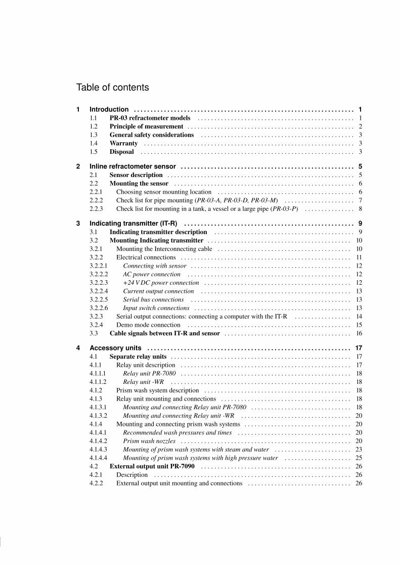
Important: Always mount the sensor so that the cable plug socket on the sensor head points downwards,i.e. so that when the interconnecting cable is plugged into the sensor, the cable hangs down.
Figure 2.3 Refractometer cable plug direction
2.2.2 Check list for pipe mounting (PR-03-A, PR-03-D, PR-03-M)
1. If the process pipe diameter varies, select the position with the smallest diameter (and accordinglyhighest velocity). Then the prism keeps better clean. If the pipe is coned up after a pump, valve ormagnetic flow meter, then add a length of straight pipe before the coning up and mount the refractometerthere.
2. If the refractometer is used in a feed-back control loop, make the time lag short. E.g. when a dilutionvalve is controlled, mount the refractometer as near the dilution point as possible.
3. If the temperature varies along the process pipe, select the position with the highest temperature. Thenthe risk of prism coating is minimized, because higher temperature means higher solubility and alsolower viscosity.
4. Often the position with the highest pressure (= after pump + before valve) has favorable flow conditionswithout sedimentation or air trapping risks.
5. The sensor should be conveniently accessible for service.
Important: If the process pipe vibrates, support the pipe. A vibrating pipe might damage the inline sensormounted on it.

14 14
14 14
8 PR-03 instruction manual
2.2.3 Check list for mounting in a tank, a vessel or a large pipe (PR-03-P)
A Probe sensor PR-03-P can be inserted with a sanitary clamp into tanks and vessels which either don’thave a scraper or where the mixer doesn’t touch the vessel wall. A Probe sensor can also be flush mountedin a cooker where the scraper touches the wall.
1. Both the inserted and the flush mounted Probe sensor are mounted on the vessel wall with the cablesocket downwards.
2. The inserted probe sensor is mounted close to a stirrer to ensure representative sample of the processliquid and to keep the prism clean.
3. The sensor should be conveniently accessible for service.
15 15
15 15
3 Indicating transmitter (IT-R) 9
3 Indicating transmitter (IT-R)
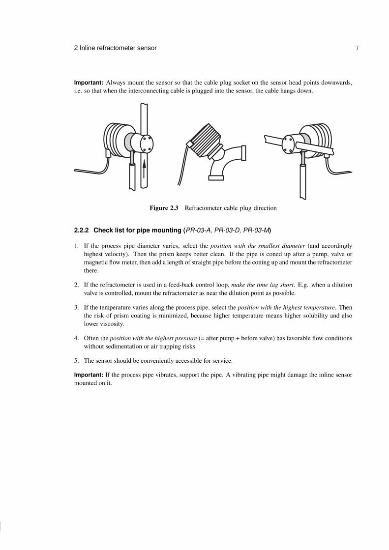
3.1 Indicating transmitter descriptionThe indicating transmitter (abbr. IT-R) is a small, specialized computer designed to process data receivedfrom the sensor. The Indicating transmitter enclosure (see Figure 3.1) contains a front panel with a LiquidCrystal Display (LCD) and a keyboard. The IT-R’s microprocessor system and the power supply are hiddenunder the front panel that swings open for service. Knockout padlock provisions for locks are included inthe enclosure’s both cover latches to prevent unauthorized access.
A B C D
7
4
1
0
8
5
2
.
9
6
3
- ENTER RESET
K-PATENTSPROCESS INSTRUMENTS
Figure 3.1 The Indicating transmitter enclosure
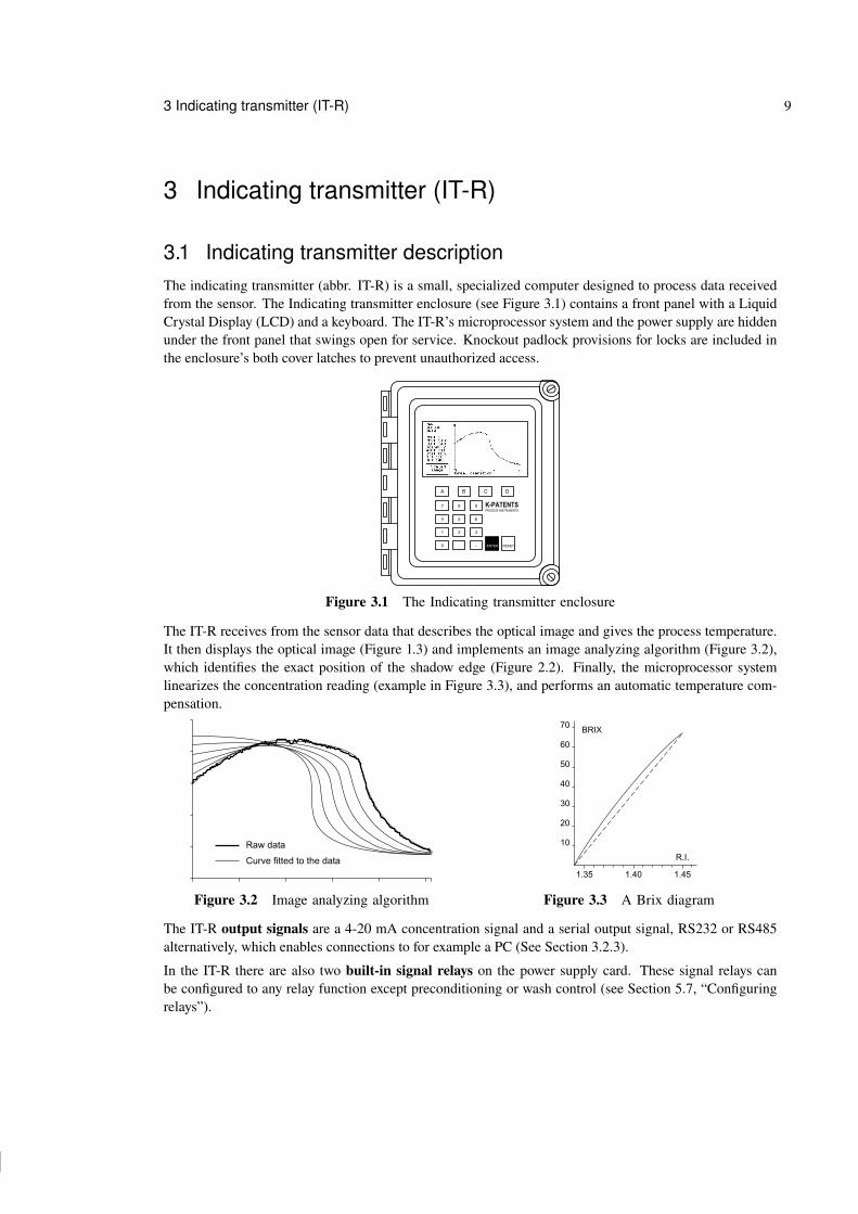
The IT-R receives from the sensor data that describes the optical image and gives the process temperature.It then displays the optical image (Figure 1.3) and implements an image analyzing algorithm (Figure 3.2),which identifies the exact position of the shadow edge (Figure 2.2). Finally, the microprocessor systemlinearizes the concentration reading (example in Figure 3.3), and performs an automatic temperature com-pensation.
Raw data
Curve fitted to the data
Figure 3.2 Image analyzing algorithm
10
20
30
40
50
60
70
1.35 1.40 1.45
R.I.
BRIX
Figure 3.3 A Brix diagram
The IT-R output signals are a 4-20 mA concentration signal and a serial output signal, RS232 or RS485alternatively, which enables connections to for example a PC (See Section 3.2.3).
In the IT-R there are also two built-in signal relays on the power supply card. These signal relays canbe configured to any relay function except preconditioning or wash control (see Section 5.7, “Configuringrelays”).

16 16
16 16
10 PR-03 instruction manual
Furthermore, the Indicating transmitter accepts four input switches which can be configured for example tosignal HOLD during external wash or to contain different scale settings each (see Section 5.6, “Configuringinput switches”).
3.2 Mounting Indicating transmitter
The Indicating transmitter should preferably be located in an easily accessible, well lighted and dry area.The enclosure must not be exposed to rain or direct sunlight. Avoid vibration. Take interconnecting cablelength into consideration when choosing mounting location.
The enclosure is mounted vertically on an upright surface (wall) using four mounting feet, see Figure 3.4.Important: Do not drill mounting holes in the enclosure as that will affect the protection class of theenclosure and may expose the electronics of the IT-R.
Figure 3.4 Mounting the Indicating transmitter
Note: The LCD display has an operating temperature range of 0–50 ◦C and a storage temperature range of-20–60 ◦C. If exposed to very low storage temperatures, let the IT-R reach the ambient temperature beforeturning it on, as the LCD may not be able to display anything in temperatures below zero.
3.2.1 Mounting the Interconnecting cable
The interconnecting cable PR-8300 is made at the K-Patents factory according to the specifications givenin your order (see Section 9.4). The maximum length of an interconnecting cable is 100 meters (330 feet).When mounting the cable, check that the ends easily reach the sensor respectively the IT-R.
Warning! Do not try to shorten or lengthen the interconnecting cable! If a new cable is needed for example!after the IT-R has been moved further away from the process line, you can order a spare part cable fromK-Patents or your local K-Patents representative.

17 17
17 17
3 Indicating transmitter (IT-R) 11
3.2.2 Electrical connections
All the electric terminals of the Indicating transmitter are on the Power supply card (Figure 3.5).
11
POWERSELECTOR
POWERCONNECTION
SERIAL CABLE(pc)
SENSORCABLE
ACCESSORY UNIT(serial bus)
SWITCHES
RELAYS
Figure 3.5 Power supply card layout
To access the Power supply card, first open the enclosure cover. Then loosen the two screws on the right-hand corners of the front panel and swing open the front panel to see the card.
Figure 3.6 IT-R with opened front panel.

18 18
18 18
12 PR-03 instruction manual
3.2.2.1 Connecting with sensor
The sensor end of the interconnecting cable is terminated by a plug. The plug goes into the cable plugsocket on the sensor head. After connecting the cable with the sensor, join the two connector protectingcaps to keep them clean inside.
The Indicating transmitter end of the interconnecting cable has leads numbered from 1 to 7 to be connectedto the terminals with the same numbers on the Power supply card. The seven leads to the plug on the cableare colored Red, Blue, Black, Red, Blue, Black and Black.
3.2.2.2 AC power connection
The primary AC power is connected to a separate terminal strip 39/40/41 marked POWER in the lowerright-hand corner of the Power supply card (Figure 3.5). The three terminals are marked 39/L, 40/N and41/ground symbol. The connection is made by inserting each lead into the corresponding slot and tighteningthe screws above the slots (Figure 3.7).
The power terminals Line and Neutral are directly connected to the transformer primary loop, and galvani-cally separated from the rest of the instrument. The ground terminal (41) is connected to the bottom plate ofthe Indicating transmitter, to the transformer shield winding and to the outer shield of the interconnectingcable.
NEUTRAL
LINE GROUND
Figure 3.7 Power terminals on the Power supply card
Important: Before connecting the IT-R power, check the position of the power selector switch, markedSW2 on the Power supply card. The power selector switch has two positions: 220–240 V/50–60 Hz or100–115 V/50–60 Hz.
Figure 3.8 Power selector switch in the 220 V position
3.2.2.3 +24 V DC power connection
The primary DC power is connected to a separate terminal strip 39/40/41 marked POWER in the lower right-hand corner of the Power supply card (Figure 3.5). The terminals are marked 39/+24V, 40/0 and 41/ground

19 19
19 19
3 Indicating transmitter (IT-R) 13
symbol. The connection is made by inserting each lead into the corresponding slot and tightening the screwsabove the slots (Figure 3.7).
The ground terminal (41) is connected to the bottom plate of the Indicating transmitter, to the transformershield winding and to the outer shield of the interconnecting cable.
Important: The power selector switch on the Power supply card, marked SW2, must be in 110 position(Figure 3.9) when input voltage is +24 V DC. If the switch is in the wrong position, the refractometer systemdoes not work.
Figure 3.9 Power selector switch in the 110 V +24 V DC position
3.2.2.4 Current output connection
The current output connection terminals are 25 and 26. The terminal 25 is plus (+) and 26 minus (-) for the4-20 mA output signal (The detailed signal specifications are listed in Section 9.4, “IT-R Specifications”).
Recorders, controllers, indicators etc. must be connected to form a closed current loop, starting from termi-nal 25 passing each device, in at plus and out at minus, ending at terminal 26.
Important: Be careful not to exceed the specified load resistance, 1800 Ohm.
3.2.2.5 Serial bus connections
Terminals 8-14 on the Power supply card provide connection to K-Patents accessory units, like a Relay Unit(see Section 4.1) and External output unit (see Section 4.2). The connection cable is of the same type as theinterconnecting cable and follows the same specifications (see Section 9.4). See Section 4.1.3, “Relay unitmounting and connections” and Section 4.2.2, “External output unit mounting and connections” for moreinformation.
3.2.2.6 Input switch connections
Altogether four input switches A, B, C and D can be connected: Terminals 27-A, 28-B, 29-C, 30-D, 31-Common, Figure 3.10. To use a switch, you will have to connect that switch with terminal 31, which shortcircuits that switch. Thus, to use switch A, connect terminal 27 with terminal 31.
The switches may be separate, or together in one rotary switch. Input switch functions are configuredthrough software, Section 5.6. Most commonly input switches are used for easy switching between calibra-tion settings for different process mediums or for preventing accidental or unauthorized calibration changes.
A 5V voltage is provided over each switch. The switch terminals are all galvanically isolated from groundand from the rest of the electronics.

20 20
20 20
14 PR-03 instruction manual
27 28 29 30 31
SWITCHES
B C DA
27 28 29 30 31
SWITCHES
D
CB
A
Figure 3.10 Input switch connections
3.2.3 Serial output connections: connecting a computer with the IT-R
The serial output connections on the Power supply card allow you to download information from the IT-Rwith a PC computer that has a 9-pin COM port (or a USB-to-COM adapter that simulates a 9-pin COMport).
Note: The serial output connection is for output only, i.e. it cannot be used to give commands to the IT-R.
To connect your PC with an IT-R to download process data, you need to order a communications packagefrom K-Patents. The package contains a cable with a plug for the P3 plug connector on the Indicatingtransmitter Power supply card. The other end of the cable is a 9-hole COM plug for your computer’s COMport.
Serial connection cable plugs Cable plugged into an IT-R
Figure 3.11 Serial (PC) connection
21 21
21 21
3 Indicating transmitter (IT-R) 15
The K-Patents communications package contains Windows software for downloading data from the IT-R.The software has been preset so that it normally starts directly after the installation and it has built-ininstructions. However, you can also use any standard communications software to download data. Insuch case see Section 9.4.2, “Serial output specifications” for more information on the data format andthe communications settings.
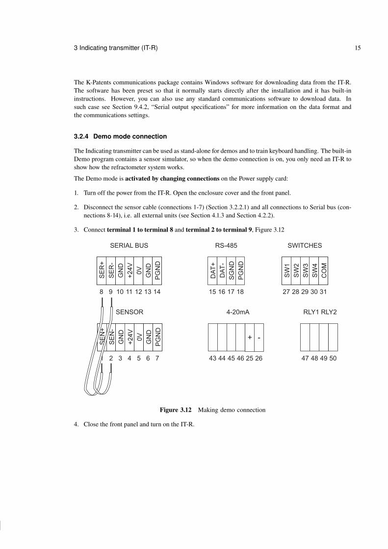
3.2.4 Demo mode connection
The Indicating transmitter can be used as stand-alone for demos and to train keyboard handling. The built-inDemo program contains a sensor simulator, so when the demo connection is on, you only need an IT-R toshow how the refractometer system works.
The Demo mode is activated by changing connections on the Power supply card:
1. Turn off the power from the IT-R. Open the enclosure cover and the front panel.
2. Disconnect the sensor cable (connections 1-7) (Section 3.2.2.1) and all connections to Serial bus (con-nections 8-14), i.e. all external units (see Section 4.1.3 and Section 4.2.2).
3. Connect terminal 1 to terminal 8 and terminal 2 to terminal 9, Figure 3.12
1
8
2
9
3
10
4
11 27
43 47
29
45 49
15
5
12 28
44 48
30
46 50
3116
6
13 17
7
14 18
SENSOR
SERIAL BUS RS-485 SWITCHES
RLY1 RLY2
25 26
4-20mA
+ -
Figure 3.12 Making demo connection
4. Close the front panel and turn on the IT-R.
22 22
22 22
16 PR-03 instruction manual
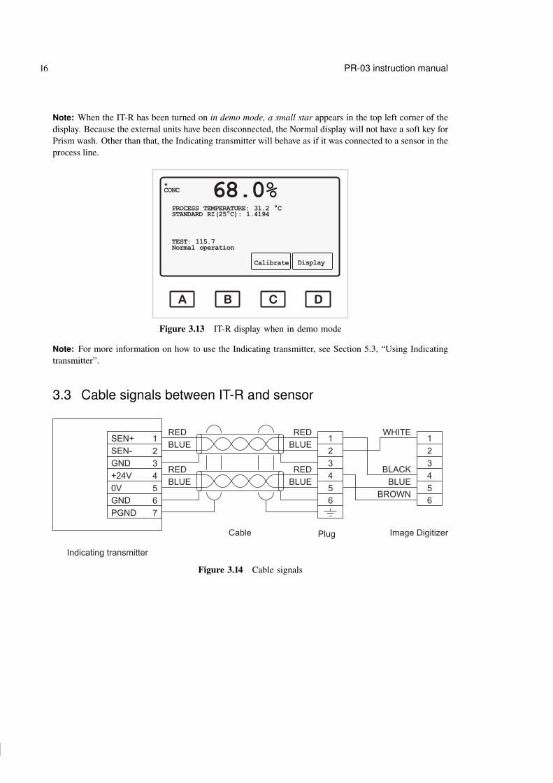
Note: When the IT-R has been turned on in demo mode, a small star appears in the top left corner of thedisplay. Because the external units have been disconnected, the Normal display will not have a soft key forPrism wash. Other than that, the Indicating transmitter will behave as if it was connected to a sensor in theprocess line.
A B C D
CONC 68.0%PROCESS TEMPERATURE: 31.2 °CSTANDARD RI(25°C): 1.4194
TEST: 115.7Normal operation
Calibrate Display
*
Figure 3.13 IT-R display when in demo mode
Note: For more information on how to use the Indicating transmitter, see Section 5.3, “Using Indicatingtransmitter”.
3.3 Cable signals between IT-R and sensor
1 1
4 4
2 2
5 5
3 3
6 6
RED
RED
RED
RED
BLUE
BLUE
BLUE
BLUE
SEN+
+24V
SEN-
0V
GND
GND
PGND
1
4
2
5
3
6
7
Indicating transmitter
Plug
WHITE
BLACK
BLUE
BROWN
Cable Image Digitizer
Figure 3.14 Cable signals

23 23
23 23
4 Accessory units 17
4 Accessory units
4.1 Separate relay units
When necessary, a K-Patents inline refractometer system can be equipped with a separate relay unit witheither four (PR-7080) or two (-WR) relays. The separate relay units can be added to any refractometer modelwhen additional relays are needed.
Unlike the built-in relays, both separate relay units can be configured for preconditioning and prism wash.That is, if a prism wash (Sanitary refractometer PR-03-A and Probe refractometer PR-03-P only) is installedbecause of sticky process medium, a separate relay unit is also needed.
4.1.1 Relay unit description
Both separate relay units are built in an enclosure with IP 65 (Nema 4X) classification. Figure 4.1 showsthe dimensions of the four-relay unit PR-7080 and the two-relay unit -WR.
PR-7080 -WR
Figure 4.1 Relay unit dimensions
To see the relays and to make all necessary connections, open the screws in the four top corners of the relayenclosure and lift off the enclosure cover.
The cable fittings are delivered as one of the three alternatives:
US 1/2 NPT-TYPE ST-1 conduit hubs 4 pcsEuropean BF11/PG11 cable glands 4 pcs
M20x1.5 cable glands 4 pcs

24 24
24 24
18 PR-03 instruction manual
4.1.1.1 Relay unit PR-7080
The Relay unit PR-7080 contains 4 relays from left to right: Relay A, relay B, relay C and relay D. There isa yellow LED above each relay. If the LED is lighted, the corresponding relay is ON and the output contactis closed. There is also one green and one red indicator led to inform on system status. After startup the redled is lighted only when the relay unit has problem.
The Relay unit PR-7080 is connected with the IT-R with an interconnecting cable PR-8011 . The last threenumbers in the cable code indicate the cable length in meters, the shortest available cable is PR-8011-001(1 meter; 3.3 feet) and the longest possible cable is PR-8011-100 (100 meters; 330 feet).
4.1.1.2 Relay unit -WR
The Relay Unit -WR contains 2 relays from left to right: Relay A and Relay B. There is a yellow LEDabove each relay. If the LED is lighted, the corresponding relay is ON and the output contact is closed.
4.1.2 Prism wash system description
Deposit build-up on the prism surface disturbs the measurement. Look out for an abnormally high concen-tration reading, low slope value or an upward CONC drift.
In most applications the prism will keep clean due to the self-cleaning effect. If coating occurs, check thefollowing:
− Sufficient flow velocity, see Section 2.2.2, “Check list for pipe mounting (PR-03-A, PR-03-D, PR-03-M)”.− A temperature difference between process fluid and sensor probe may cause coating. This may happen
with small flows if the thermal insulation is inadequate. In some cases it helps to insulate also the clampconnector.
In case of a coating problem, the preferred solution is to try to increase the flow velocity, e.g. by installinga pipe portion with smaller diameter. Installing a wash nozzle can be considered, if increasing the velocitydoes not provide a solution (Section 4.1.4).
Three alternative media can be used for prism wash: steam, water, high pressure water. Only external relays(accessory units) can be configured to control the prism wash cycle, see Section 5.9 “Configuring automaticprism wash”.
4.1.3 Relay unit mounting and connections
Note: When mounting a separate relay unit, seal all unused fittings with blind washers.
4.1.3.1 Mounting and connecting Relay unit PR-7080
The four-relay Relay unit PR-7080 is mounted on a wall or similar vertical surface using its four mountingfeet. Take the length of the interconnecting cable PR-8011 and easy access for service into account whenchoosing mounting spot for the Relay unit.
Open the screws on the Relay unit and lift off cover to get access to the relay card to make the connections.The relay contacts go to the connector strip (Figure 4.2) on the relay unit card.

25 25
25 25
4 Accessory units 19
A B C D
44 46 48 5045 47 49 51
Figure 4.2 Relay unit PR-7080 connector strip
Connect the numbered leads of the interconnecting cable with the same numbers (8-14) on the serial bus.Then proceed to connect the cable with your refractometer system. If you have an External output unit, theRelay unit is connected to that. If no other external units are used, the Relay unit connects directly with theIT-R (Figure 4.3).
Indicatingtransmitter
Indicatingtransmitter
8-14
8-14
8-14 8-14
8-14
8-14
A B
External output unit Relay unit
Relay unit
PR-8011
PR-8011
PR-8011
Figure 4.3 Connecting Relay unit PR-7080
Important: Before connecting the relay unit with your refractometer system, power off your system. If youhave an external output unit, open its cover to access the card inside for connections. If you don’t have anexternal output unit, open the IT-R’s enclosure and display panel to access the processor card.
Connect the numbered leads of the free cable end with terminals with the same numbers (8-14) on theserial bus output (serial bus B) on the Output unit card or on the serial bus on the Indicating transmitter’sprocessor card.

26 26
26 26
20 PR-03 instruction manual
4.1.3.2 Mounting and connecting Relay unit -WR
The Relay unit -WR is always mounted directly underneath the IT-R. If the IT-R and the Relay unit -WR aredelivered together, they are already fully connected. If the Relay unit is delivered separately, the connectioncable is included in the Relay unit delivery. The cable is plugged in the P2 plug on the IT-R’s processorcard (next to the sensor cable, see Figure 3.5). The relay contacts go to the connector strip.
4.1.4 Mounting and connecting prism wash systems
The prism wash system for steam is described by Figures 4.7 and 4.8 and for high pressure water by Fig-ure 4.9.
4.1.4.1 Recommended wash pressures and times
The recommended wash pressures and times are given in Table 4.1 below.
Wash medium pressure
Minimum Maximum Wash time Recovery Interval
above process allowed
pressure pressure
Steam 2 bar (30 psi) 6 bar (90 psi) 3–5 s 20–30 s 20–30 min
Water 2 bar (30 psi) 6 bar (90 psi) 10–15 s 20–30 s 10–20 min
High pressure water 40 bar (600 psi) 70 bar (1000 psi) 10–15 s 20–30 s 10–20 min
Table 4.1 Recommended prism wash parameters
Important: In steam wash, do not exceed the recommended wash times, because some process media mayburn to the prism surface if steamed for longer time. In case of coating, shorten the wash interval.
Note: In water wash, water temperature should be above the process temperature.
Note: The check valve pressure drop is 0.7 bar (10 psi).
4.1.4.2 Prism wash nozzles
Select wash nozzle according to wash medium and refractometer model, Table 4.2.
PR-03-A
Pressurized water sanitary nozzle -WP PR-3366
Steam sanitary nozzle -SN PR-3365
Water nozzle -WN PR-3364
Table 4.2 Prism wash nozzle selection

27 27
27 27
4 Accessory units 21
The three versions of a prism wash nozzle are shown in Figure 4.4. How they are mounted to the process isshown in Figure 4.5, which also shows the connection of a check valve. K-Patents provides flow cells withstud for a wash nozzle. Figure 4.6 shows an example with the correct position of the nozzle in relation tothe prism surface.
Figure 4.4 Wash nozzle selection

28 28
28 28
22 PR-03 instruction manual
Figure 4.5 Process connection of a wash nozzle
Figure 4.6 Example of wash nozzle installed in a flow cell

29 29
29 29
4 Accessory units 23
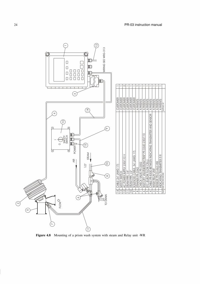
4.1.4.3 Mounting of prism wash systems with steam and water
8
STEA
M
PART
SPEC
IFIC
ATI
ON
SPA
RT
SUPPLI
ED
BY
FLO
W
6
2
RELA
Y U
NIT
PR-7
08
0
TO D
RA
INW
IRIN
G S
EE W
RG
-31
4
1/2
"1
2
11
9
7
CA
BLE
PR-8
01
1 B
ETW
EEN
IND
ICATI
NG
TRA
NSM
ITTE
R A
ND
RELA
Y U
NIT
SHU
T-O
FF V
ALV
E&
STEA
M T
RA
P P
R-3
34
0-2
30
/11
0
CA
BLE
PR-8
30
0 B
ETW
EEN
IND
ICATI
NG
TRA
NSM
ITTE
R A
ND
SEN
SOR
IND
ICATI
NG
TRA
NSM
ITTE
R IT
-R
EFC
(ELB
OW
FLO
W C
ELL
)
SEN
SOR P
R-0
3-A
62
-HSS
RELA
Y U
NIT
PR-7
08
0
7 6 5 4 123
K-PA
TEN
TS
K-PA
TEN
TS
K-PA
TEN
TS
K-PA
TEN
TS
K-PA
TEN
TS
K-PA
TEN
TS
1 1 1 1 111
5
AC
PO
WER S
UPPLY
23
0/1
10
V
SOLE
NO
ID C
ABLE
, 3
x1 (A
WG
17
)
STEA
M P
IPE 1
/4"
STRA
INER P
R-3
34
2
STEA
M P
IPE 1
/2"
CH
EC
K V
ALV
E P
R-3
30
2
13
11
10
12 9 8
10
4 133
CU
STO
MER
CU
STO
MER
CU
STO
MER
CU
STO
MER
2 1 11 1 11
131
K-PA
TEN
TS
K-PA
TEN
TS
K-PA
TEN
TS
AIR
Figure 4.7 Mounting of a prism wash system with steam and Relay unit PR-7080
30 30
30 30
24 PR-03 instruction manual
STEA
M
AIR
PART
SPEC
IFIC
ATI
ON
SPA
RT
SUPPLI
ED
BY
SWITC
H
PO
WER
SAFE
TY
0
I
5
FLO
W TO D
RA
IN
1/2
"
WIR
ING
SEE W
RG
-31
31
08
6
SHU
T-O
FF V
ALV
E&
STEA
M T
RA
P P
R-3
34
0-2
30
/11
0
CA
BLE
PR-8
30
0 B
ETW
EEN
IND
ICATI
NG
TRA
NSM
ITTE
R A
ND
SEN
SOR
IND
ICATI
NG
TRA
NSM
ITTE
R IT
-R
EFC
(ELB
OW
FLO
W C
ELL
)
SEN
SOR P
R-0
3-A
62
-HSS
WA
SH R
ELA
Y U
NIT
6 5 4 123
K-PA
TEN
TS
K-PA
TEN
TS
K-PA
TEN
TS
K-PA
TEN
TS
K-PA
TEN
TS
1 1 1 111
AC
PO
WER S
UPPLY
23
0/1
10
V
SOLE
NO
ID C
ABLE
, 3
x1 (A
WG
17
)
STEA
M P
IPE 1
/4"
STRA
INER P
R-3
34
2
STEA
M P
IPE 1
/2"
CH
EC
K V
ALV
E P
R-3
30
2
13
12
10 911 8 7
CU
STO
MER
CU
STO
MER
CU
STO
MER
CU
STO
MER
2 1 11 1 11
9
12
12
4
3
11
3
SAFE
TY S
WITC
H1
7
2
11
K-PA
TEN
TS
K-PA
TEN
TS
K-PA
TEN
TS
CU
STO
MER
14
CU
STO
MER
CA
BLE
2x1
(A
WG
17
)1
14
Figure 4.8 Mounting of a prism wash system with steam and Relay unit -WR

31 31
31 31
4 Accessory units 25
4.1.4.4 Mounting of prism wash systems with high pressure water
Warning! In high pressure wash systems, pressure increase can occur in a closed pipe section when the!high pressure pump is operated. K–Patents recommends to mount a pressure relief valve in the pipe section.Relief pressure should be according to pipe pressure rating.
FLO
W
PART
SPEC
IFIC
ATI
ON
SPA
RT
SUPPLI
ED
BY
TAP W
ATE
R,
TEM
P M
AX
60
°C
/ 1
40
°F
SWITC
HM
AIN
PO
WER
PO
WER0
I
3/8
"
PO
WER R
ELA
Y U
NIT
PR-3
60
3-_
__
12 9 1234568 711
CU
STO
MER
AC
PO
WER S
UPPLY
23
0/1
10
V
CA
BLE
BETW
EEN
IND
ICATI
NG
TRA
NSM
ITTE
R A
ND
SEN
SOR P
R-8
30
0
IND
ICATI
NG
TRA
NSM
ITTE
R IT
-R
EFC
(ELB
OW
FLO
W C
ELL
)
WA
SH R
ELA
Y U
NIT
(W
R)
SEN
SOR P
R-0
3-A
62
-HSS
CH
EC
K V
ALV
E R
1/4
" PR-3
30
2
HIG
H P
RESS
URE H
OSE
8M
K-PA
TEN
TSK-
PATE
NTS
K-PA
TEN
TS
K-PA
TEN
TS
K-PA
TEN
TS
K-PA
TEN
TS
K-P / C
UST
OM
ER
PO
WER S
UPPLY
CA
BLE
3 M
ETE
RS
FOR W
ATE
R V
ALV
E
HIG
H P
RESS
URE P
UM
P P
R-3
60
2-1
10
/23
0/4
00
/55
0 IN
CLU
DIN
G W
ATE
R V
ALV
E
CU
STO
MER
2 111111111
81
9
7
10
8
11
12
10
PO
WER R
ELA
Y U
NIT
PR-3
60
3-1
10
/23
0/4
00
/55
0K-
PATE
NTS
1
PO
WER S
UPPLY
CA
BLE
3 M
ETE
RS
FOR H
IGH
PRESS
URE P
UM
PK-
PATE
NTS
1
3
4
6
2
5
K-PA
TEN
TS
13
13
CA
BLE
2x1
(A
WG
17
)C
UST
OM
ER
1
Figure 4.9 Mounting summary of prism wash system for high pressure water with -WR relay unit
32 32
32 32
26 PR-03 instruction manual
4.2 External output unit PR-7090
The K-Patents inline refractometer can be provided with a separate current output unit to give e.g. a tem-perature mA signal.
4.2.1 Description
The External output unit PR-7090 has the same dimensions as the four-relay unit PR-7080 (Figure 4.1).The enclosure has IP 65 (Nema 4X) classification. To open the enclosure, loosen the screws in the four topcorners of the enclosure and lift off cover. This will give access to the output unit’s circuit card.
The cable fittings are delivered as one of the three alternatives:
US 1/2 NPT-TYPE ST-1 conduit hubs 4 pcsEuropean BF11/PG11 cable glands 4 pcs
M20x1.5 cable glands 4 pcs
The mA output range of the Output unit is the same as the built-in mA output of the IT-R, i.e. either4-20 mA or 0-20 mA. The output range is chosen through the IT-R’s software, see Section 5.8.
Two monitoring LEDs on the output unit’s circuit card indicate its status: Green LED L1 is lit when theoutput unit is in order. Red LED L2 is lit when correct input data are missing. Red light means that either theconnection to the IT-R is broken (no interconnecting cable, badly plugged cable or dead cable) or that there’sa problem on either the output unit’s circuit card or the IT-R’s processor card. Under normal operation thegreen LED should be lighted and the red LED should be dark.
The External output unit is connected with the IT-R with an interconnecting cable PR-8011 . The last threenumbers in the cable code indicate the cable length in meters, the shortest available cable is PR-8011-001(1 meter; 3.3 feet) and the longest possible cable is PR-8011-100 (100 meters; 330 feet).
4.2.2 External output unit mounting and connections
Note: Seal all unused fittings with blind washers.
The External output unit PR-7090 is mounted on a wall or similar vertical surface using its four mountingfeet. Take the length of the interconnecting cable(s) PR-8011 and easy access for service into account whenchoosing mounting spot for the External output unit.
Open the screws on the External output unit and lift off cover to get access to the circuit card to make theconnections. The output mA signal is connected to the terminals 42+ and 43-.
Connect the numbered leads of the interconnecting cable with the same numbers (8-14) on the serial bus Aon the circuit card. If you have a Relay unit PR-7080, the Relay unit’s interconnecting cable is connected tothe Serial bus B.
Important: If the refractometer system does not include a Relay unit PR-7080, close the circuit with a120 Ohm closing resistor (Figure 4.10).

33 33
33 33
4 Accessory units 27
Indicatingtransmitter
Indicatingtransmitter
8-14
8-14
8-14
8-14
8-148-14
A
A
B
B
External output unit
External output unit
Relay unit
120Ohm
8 9
PR-8011
Indicatingtransmitter
8-14 8-14
A B
External output unit
120Ohm
8 9
-WR
PR-8011
PR-8011
PR-8011
Figure 4.10 Connecting External output unit
Important: Before connecting the Output unit with your refractometer system, power off your system. Thenopen the IT-R’s enclosure and display panel to access the processor card.
Connect the numbered leads of the free cable end with terminals with the same numbers (8-14) on theserial bus on the Indicating transmitter’s processor card (if there’s an earlier Relay unit connection, movethe Relay unit’s interconnecting cable to the Output unit’s circuit card, serial bus B, and then connect theOutput unit with the IT-R).

34 34
34 34
28 PR-03 instruction manual

35 35
35 35
5 Startup, configuration and calibration adjustment 29
5 Startup, configuration and calibration adjustment
5.1 StartupFirst check that the serial number of your sensor (Figure 8.1) and your Indicating transmitter (Figure 9.1)match. If you ordered a new sensor to go with an old IT-R, ask K-Patents to send a new label for your IT-R.
Check wiring and supply voltage, Section 3.2.2.
Open the IT-R cover and press the main power switch (Figure 5.1) underneath down to ON position to powerup your refractometer system.
POWER
OFF 0
ON I
Figure 5.1 The power switch
5.2 System checkAfter the power has been switched on, the IT-R checks the type of the sensor, which should be identifiedas PR-03. The sensor code PR-03 is shown on the display for a short time. Then the Normal display(Figure 5.2) appears. The diagnostic message should be Normal operation or, if the process pipe isempty, Low conc/no sample. For any other message see Section 9.7.
A B C D
CONC 68.0%PROCESS TEMPERATURE: 31.2 °CSTANDARD RI(25°C): 1.4194
TEST: 115.7Normal operation
Calibrate Display
A B C D
CONC 68.0%PROCESS TEMPERATURE: 31.2 °CSTANDARD RI(25°C): 1.4194
TEST: 115.7Normal operationStartprismwash
Calibrate Display
Without wash With wash
Figure 5.2 Normal displays
The display also shows the current process temperature.
The TEST value in the display should be in the range of 8-248. The value 248 indicates a clean prism in anempty process pipe. The value 8 means that the prism is coated and no reliable optical image is available.
As the instrument is precalibrated to your process, the concentration reading should be on scale, although itmay need some final adjustment (see Section 5.10.1). If the concentration reading is off, check your processconditions (see Section 7, “Troubleshooting and correcting problems”).

36 36
36 36
30 PR-03 instruction manual
Press the key D (soft key Display) for additional data, e.g. output in mA. Further data is obtained in theInformation display by soft keys Optical image (Figure 5.3), System configuration and Sensorhead. Return to Normal display by pressing the RESET key as many times as necessary.
Note: Use the keyboard’s keys A, B, C, D for the soft key commands, do not touch the display screen (seeSection 5.3.1).
A B C D
CONC 36.7%TEMPERATURE: 30.2 °C 86.4 °FSTANDARD RI(25°C): 1.3960
TEST: 133.6Normal operation
Opticalimage
Systemconfigur-ation
Sensorhead
Output signal: 16.7 mA
A B C D
RI(25ºC
1.4412PR-03 version 8.5Sensor interface version 4.0Sensor processor version 4.0Relay unit not connectedExternal output unit not connected
Output: 4..20 mA = 1.4260..1.4900 RI(25
Relayconfigur-ation
Switchconfigur-ation
Washtimes
A B C D
RI(25ºC
1.4412SENSOR HEAD
Head temperature: 20 ºCHead humidity: 32 %
Normal operation
Information display System configuration display Sensor head display
Figure 5.3 Getting additional information
Measure the output signal. It should agree with the mA display.
If there are problems in the system check, proceed to Chapter 7, “Troubleshooting and correcting problems”.
5.2.1 Checking accessory units
All the accessory units, both relay units -WR and PR-7080 and external output unit, have two indicatorLEDs that tell about their status. Open the enclosure cover to see these LEDs. When the refractometersystem is on and the IT-R is finished with the initial check (i.e. the Normal display has appeared, see atpage 29), only the green led should be lit. If the red led stays lit, there’s problem in the accessory unitconfiguration, see Section 5.7 and Section 5.8.
Note: When the refractometer system is powering up, both LEDs light up for a short time during the systemcheck. After a while the red led should be turned off, in a working system only the green led is lit.
5.2.2 Testing prism wash
Important: Before you test prism wash, check that there is liquid in the pipe in front of the refractometerand that the steam washing parts are properly installed and connected.
If you are using prism wash controlled by a relay unit check the wash sequence by pressing in the Nor-mal display soft key Startprismwash (Figure 5.2). The TEST value should clearly increase (and theconcentration reading decrease) during wash.
Note: The manual wash command cannot override External hold (see Section 5.6).
Note: The Startprismwash soft key appears in the Normal display only when a relay has been con-figured as wash relay (Section 5.7). In demo mode it never appears, because the external units have beendisconnected.

37 37
37 37
5 Startup, configuration and calibration adjustment 31
5.3 Using Indicating transmitter
5.3.1 Keyboard functions
The keyboard has 10 number keys and four soft keys, marked with letters A-D. The meaning of a soft keychanges depending on what has been entered previously, i.e. what display is shown. The meaning of a softkey is always displayed on the screen above the key, for example the Normal display always has soft keysC=Calibrate and D=Display and, if the system has prism wash, also A=Start prism wash (seeFigure 5.4).
The ENTER key is used to accept entered numeral values (to "OK" them) and the RESET key is used tocancel input and to move "backwards" in the command structure.
The commands that can be given to the Indicating transmitter have been arranged into a selection tree, i.e.command groups and subgroups (see Figure 9.5). The "root" of the selection tree is the Normal display(Figure 5.4), to which the IT-R always returns if it doesn’t receive any keyboard commands for a predefinedreset time (normally 60 seconds).
A B C D
CONC 68.0%PROCESS TEMPERATURE: 31.2 °CSTANDARD RI(25°C): 1.4194
TEST: 115.7Normal operation
Calibrate Display
A B C D
CONC 68.0%PROCESS TEMPERATURE: 31.2 °CSTANDARD RI(25°C): 1.4194
TEST: 115.7Normal operationStartprismwash
Calibrate Display
Figure 5.4 Normal display
Each command in the selection tree can be reached from the Normal display with its own, unique keysequence. For example you can view the relay configuration with the sequence D (Display) - C (Systemconfiguration) - A (Relay configuration), i.e. starting from the Normal display, press first softkey D, then soft key C, then soft key A. After viewing the configuration you can go backwards to the Normaldisplay by pressing the Reset key three times.
Whenever New value: _ _ _ _ is displayed, new parameter values can be entered by the numericalkeys. If you accidentally enter a wrong number, you can erase it with RESET. When the number (value)is complete, press ENTER. After this the IT-R will ask for reconfirmation with the following text: PressENTER to change (Otherwise press RESET). Thus, press ENTER if you want the new valueto become effective. If you want to discard the new value and return to the old value, press RESET.

38 38
38 38
32 PR-03 instruction manual
Example: You need to change the bias (see Section 5.10.2) to be 25.456 (as in the example inSection 5.10.2). Starting from the Normal display (Section 5.3), you have to perform followingsteps:
1. Give the right command sequence to get to the value to be changed, in this caseCalibrate/Parameters/CONC (R.I.)/Parameters/Bias(key sequence C-B-A-A-1).
2. Type the new value.3. When the new value is finished, press ENTER.4. Accept (=reconfirm) the new value by pressing ENTER again. The new value now appears on
the screen as the current value.5. Finally, withdraw from the current display by pressing the RESET key as many times as neces-
sary (five times to get to the Normal display from the Bias setting).
5.4 Soft key Display: Getting information on the processand the settings
Pressing the soft key Display (key D) in the Normal display brings up the Information display , Fig-ure 5.5 below. Through the Information display you can get information about the process, the processparameters and other settings that have been entered to the Indicating transmitter. This branch of the se-lection tree (Figure 9.5) is safe, because it doesn’t allow you to make changes to the settings, it will onlydisplay the existing information.
A B C D
CONC 36.7%TEMPERATURE: 30.2 °C 86.4 °FSTANDARD RI(25°C): 1.3960
TEST: 133.6Normal operation
Opticalimage
Systemconfigur-ation
Sensorhead
Output signal: 16.7 mA
Figure 5.5 The Information display
As you can see in Figure 5.5, the Information display contains additional data compared to the Normaldisplay:
− The process temperature in both ◦C and ◦F− The standard RI (25 ◦C). This shows the Refractive Index of liquid applied to the prism, referenced to
25 ◦C− output current in mA

39 39
39 39
5 Startup, configuration and calibration adjustment 33
5.4.1 Viewing the Optical image
You can view the Optical image (Figure 5.6) by pressing the soft key Optical image (key A) in theInformation display. The light area (high pulses) is to the left, the dark area (low pulses) is to the right,compare to Figure 2.2. The vertical scale is 0–100 % of highest pulse amplitude, the horizontal scaleexpresses the numbers of the photocells 0–1024.Figures 5.6 below show some typical optical images appearing at startup.
A B C D
Slope
TEST: 248.030.2 ºCEndp: 11L): 30.5R(: 5.3HT: 20 ºCHH: 4 %
SCALEDOPTICALIMAGE
Low concentration / No sample
A B C D
Slope
TEST: 133.630.2 ºCEndp: 11L): 16.5R(: 30.3HT: 20 ºCHH: 4 %
SCALEDOPTICALIMAGE
Normal operation
Empty pipe Normal conditions
Figure 5.6 Typical optical images
Press the RESET key to return to the Information display from the Optical image display.
5.4.2 Viewing System configuration
You can view the System configuration, i.e. information about your refractometer system settings, by press-ing the soft key C (= System configuration) in the Information display. The System configurationdisplay contains:
− Main program and sensor processor and sensor interface processor versions− Connection and processor versions of accessory units− Current output scale: E.g. 4–20mA = 40.0–60.0CONC%− Three soft keys:− Relay configuration (key A); for details see Section 5.7, “Configuring relays”.− Switch configuration (key B); for details see Section 5.6, “Configuring input switches”.− Wash times (key C); for details see Section 5.9, “Configuring automatic prism wash”.
Press the RESET key to return to the Information display from the System configuration display.
5.4.3 Checking conditions inside sensor head
By pressing the soft key D (= Sensor head) in the Information display you will find out what theconditions are inside the sensor head:
− Head temperature− Head humidity
This is very useful information when suspecting a problem in the sensor head, for details see Section 7.2.2.

40 40
40 40
34 PR-03 instruction manual
5.5 Soft key Calibrate: Viewing and changing system settings
5.5.1 Viewing Optical image and raw data
It is possible to view all raw data from the sensor including the optical image followed by the ScaledImage, Slope and Image Diagnostics displays (see the selection tree, figure 9.5). Starting from the Normaldisplay, select Calibrate/Optical image to get the complete optical image. The display (Figure 5.7)contains now all raw data from the Sensor including the signals from each photo cell, i.e. the raw videosignal. This differs from the Optical image, Figure 5.6, selected through the Display key.
A B C D
RAWSENSORDATA
RMN: 2RMX: 216LED: 96Scans: 2A/D: 314Sts: 00hHT: 143HH: 10
Scaledimage
Normal operation
Figure 5.7 Complete optical image with raw data
For information on the diagnostic messages shown on this screen, see Section 9.7.
5.5.2 Raw data explanations
RMN, RMX Minimum and maximum of the raw video signal. This signal is calculated on the Processorcard from the video signal. The scale is 0-255, corresponding to full scale on display. Thelight intensity is controlled to keep RMX in the range 170-190.
LED The LED exposure control signal on a light intensity scale 1-255. The flashing red light ofthe LED can be seen directly. If the operation is correct, the displayed LED value should beabove 20 and below 200.
Scans Number of optical images during one calculation cycle, typically 1 or 2. The scan pulses(with 5 V amplitude) can be measured at TP 3
A/D This refers to the temperature measurement
Sts Sensor status bits determined by the type of Image Detector card: "04h" indicates a Processrefractometer PR-03. One bit added, "05h", indicates DETECTOR TIMEOUT.

41 41
41 41
5 Startup, configuration and calibration adjustment 35
HT Sensor head temperature sensor reading. This value is used in calculating the actual Sensorhead internal temperature.
HH Sensor head humidity sensor reading. The actual relative humidity inside the sensor is cal-culated from HH and HT.
5.5.3 Viewing Scaled image
In the scaled image (Figure 5.8) the optical image has been modified mathematically to make a clearercurve.
A B C D
SCALEDOPTICALIMAGE
TEST: 115.951.2 °CEndp: 21L): 9.8R): 25.9HT: 20 °CHH: 3%
SlopeNormal operation
Figure 5.8 Scaled image display
The Scaled image display provides following information:
TEST: The calculated TEST value, i.e. the number of photocells on the lisght side of the optical image(to the left fo the vertical line). Range 8–248. Indicated by a dotted vertical line.
(T) Indicates the process temperature.Endp: The vertical intensity value of the rightmost point in % of span.L): A measure of the left side curvature of the optical image.R(: A measure of the right side curvature of the optical image.
A zero curvature indicates a straight line. Both curvature values are defined as positive for animage as Figure 5.5.3.
HT: Sensor head internal temperature in ◦C.HH: Sensor head internal relative humidity in %RH.
5.5.4 Viewing slope
The Slope display (Figure 5.9) shows the slope curve of the optical image. Slope is a measure of thesharpness of the optical image.
The SLOPE curve should have a sharp dip at the TEST value. The following additional values are given:

42 42
42 42
36 PR-03 instruction manual
A B C D
Diagnos-tics
SLOPE
TEST: 115.731.2 °CMax: 208Slope: 2.7Endp: 21L): 10.1R(: 25.8
Normal operation
Figure 5.9 Slope display
Max: The filtered value of the maximum light intensity RMX of the raw data (Figure 5.7).Slope: The absolute value of the slope curve dip at TEST. The value of Slope must be above 1 to be
acceptable.
5.5.5 Viewing Image diagnostics
The Image diagnostics display lists the critical values for TEST acceptance:
Max intensity OK (above 100)? Yes/NoEndpoint below 75 %? Yes/NoImage below corner? Yes/NoSlope OK (above 1)? Yes/NoLeft curve OK (above 1)? Yes/NoRight curve OK (above 1)? Yes/No
For measurement with a normal sample, all answers should be Yes. A message Dip in image mayappear if the optical image is irregular.
5.6 Configuring input switches
To reach the input switch configuration settings from the Normal Display, use the command sequenceCalibrate/Parameters/Switch inputs.
The microprocessor accepts four switch inputs: A, B, C and D (for connections see 3.10). The function ofeach switch can be individually defined from one of the following five alternatives:
0 Not defined (factory setting).1 Scale select Select parameters for alternative process mediums. There are all to-
gether four alternative mediums selectable by closure of the corre-sponding switch. If no selection switch is closed, the normal mediumis selected. Maximum number of mediums is five (Normal, A, B, C,

43 43
43 43
5 Startup, configuration and calibration adjustment 37
A B C D
RI(25ºC
1.4412SWITCH INPUT A (Not defined)
0 Not defined1 Scale select2 Ext hold & wash start3 External wash stop4 Calibration seal
SwitchB
SwitchC
SwitchD
Figure 5.10 Switch input display for input A
D).Note: The range will not change.Example: medium 1 = 20 - 40 % Sugar, medium 2 = 20 - 40 % Salt.
2 Ext hold & wash start Remote wash start for Relay unit wash function and external Hold.This switch function is useful for an intermittent process: the prismis washed when the process stops and again when it starts, betweenthe two washes the output signal is on Hold.Only Sanitary refractometer PR-03-A, Probe refractometer PR-03-Pand Process refractometer PR-03-D.
3 External wash stop Only Sanitary refractometer PR-03-A, Probe refractometer PR-03-Pand Process refractometer PR-03-D.
4 Calibration seal An input switch can be configured for calibration seal. Activating andconnecting the input switch for calibration seal will prevent calibra-tion through software.
5.7 Configuring relays
You can check the existing relay configuration and functions with the Indicating transmitter. Press thekey sequence Display/System configuration/Relay configuration to display the currentrelay settings.
The default setting for built-in signal relay 1 is No malfunction and for signal relay 2 Internalhumidity above 50%. A closed contact on the Relay 1 indicates that the instrument works properly.It is recommended to use this relay for alarm purpose in a control system.
In relay units, Relay B is configured for wash by default.
You can reprogram the relay functions any time through the IT-R’s calibration menu by performing thefollowing steps:

44 44
44 44
38 PR-03 instruction manual
1. Press Calibrate/Parameters/Relays.
2. For built-in relays select either soft key A, Relay1, or soft key B, Relay2.For a relay unit select key 3, Relay unit and then select the relay to be programmed (in -WR relaysA and B, in PR-7080 relays A, B, C, D).
3. Select the relay function
0 Not defined1 Processor OK The relay is ON if the processor is running2 Normal operation The relay is ON if the diagnostic message is
Normal operation.3 No malfunction The relay is ON if the diagnostic message is
Normal operation or Low conc/no sample.4 Low limit Low alarm relay, relay is ON if value below limit.
First choose an alarm source from the following list:− CONC %− Standard RI (25 ◦C)− TEMP ◦C− TEMP ◦F− TEST− Sensor temperature− Sensor humidity
Then enter a alarm limit. The default value of the limit is zero.5 High limit High alarm relay, relay is ON if value above limit.
First choose an alarm source from the following list:− CONC %− Standard RI (25 ◦C)− TEMP ◦C− TEMP ◦F− TEST− Sensor temperature− Sensor humidity
Then enter a alarm limit. The default value of the limit is zero.6 Preconditioning A preconditioning relay. Relay unit only.7 Wash A wash relay. Relay unit only.8 In divert control Not used with PR-03.
Important: An alarm relay configuration always requires the following information: high or low limit,alarm source and alarm limit. The configuration is not complete until all the information is entered tothe IT-R.
Note: If needed, you can adjust alarm delay by pressing the key 4, Alarm delay in the Relays display(Calibrate / Parameters / Relays). The same delay applis to all relays and is used to preventoversensitive alarms. The source value has to be out of limits during the whole delay time, given in seconds,to activate the relay. The default value for the alarm delay is ten seconds.

45 45
45 45
5 Startup, configuration and calibration adjustment 39
5.8 Configuring external output unit
To program the External output unit from the keyboard of the Indicating transmitter, start with the sequenceCalibrate / Parameters / Output signals / External output to get the Externaloutput unit display (Figure 5.11).
A B C D
RI(25ºC
1.4412EXTERNAL OUTPUT UNIT (Not connected)
1 Zero (0.0000)2 Span (0.0000)3 Hold function (Active)4 Range (4..20 mA)5 Source (Not defined)
Figure 5.11 External output unit display
1 Zero Measurement value corresponding to 4 mA or 0 mA (depending on your cho-sen range)
2 Span Measurement value span corresponding to mA output span3 Hold function Select either 0 Inactive or 1 Active4 Range Select either 0 4..20 mA or 1 0..20 mA5 Source Select from
0 Not defined1 RI (25 ◦C)2 Standard RI (25 ◦C)3 Temp ◦C4 Temp ◦F5 TEST6 Sensor temperature7 Sensor humidity
Example: For source ◦C, zero = 20, span = 80, the output signal 4 - 20 mA corresponds to 20-100 ◦C.
5.9 Configuring automatic prism wash
The relay units -WR and PR-7080 can be configured to control prism wash. Automatic prism wash can beinitiated with regular intervals (Section 5.9.1) or based on certain measurement values (Section 5.9.2). Itis also possible to configure these automatic wash functions so that they are not used when the process isstopped or the pipe is empty (Section 5.9.3 and Section 5.9.4).

46 46
46 46
40 PR-03 instruction manual
5.9.1 Timed wash
When an external relay unit is used as a wash timer, the time settings are entered after the sequence Cali-brate / Parameters / Prism wash:
− Preconditioning time s (0)− Wash time, s (3)− Recovery time, s (30)− Wash interval, min (20)
The default values for timed wash are given in parenthesis. The output signal is locked during wash andrecovery time.
WASH
RECOVERY
INTERVAL
PRECOND.
Figure 5.12 Prism wash sequence
Note: The wash interval timer starts a wash at a preset interval after last wash, independently of how thelast wash was initiated. If the wash interval is set to zero, the timer will not initiate a wash.
Wash type Time Pressure Recovery Interval
Steam wash 3-5 sec. 5-6 bar (73-87 psi) 20-30 s 20-30 minHigh pressure water wash 10-15 sec. 20-30 bar (290-435 psi) 20-30 s 10-20 min
Table 5.1 Recommended prism wash times for the PR-03 sensors
Important: In steam wash, do not exceed the recommended wash times, because some process media mayburn to the prism surface if steamed for longer time. In case of coating, shorten the wash interval.
5.9.2 Smart wash
Sometimes it is necessary to modify the standard wash routine to fit the application better. The Smart washfeature allows you define better when wash is needed and when it should not be implemented.
The Smart wash starts the wash when the prism shows signs of being coated. An early indicator of beginningcoating is that the Slope decreases. Slope is a measure of the sharpness of the optical image (Section 5.5.4).
The Smart wash settings are made at Calibrate / Parameters / Prism Wash / Smartwash:
Slope limit A wash is initiated when the Slope value goes below this limit. The Slope limit has tobe set based on observations of slope values both at clean prism and at slight coating.When the slope limit is set to zero, this Smart wash function is inactive.

47 47
47 47
5 Startup, configuration and calibration adjustment 41
Minimum time This parameter sets a limit to how often the Smart wash is allowed to start a wash, itsrange is 0–1440 min.When this parameter is zero, the Smart wash function is inactive.
Maximum test This parameter should normally be set to zero. Then it will not influence the Smartwash function. It may be used for fine-tuning: The Smart wash will initiate wash onlyif the Test value is below Maximum test.
5.9.3 Preventing automatic wash
Note: The preconditioning and wash relays are not activated by automatic wash start under Low conc /no sample as this indicates a clean prism in an empty process line, i.e. there is no need for washing theprism.
Wash can be prevented when the process temperature is below a limit. The Wash stop function is used toprevent steam wash when the process pipe is empty or when the process is stopped. To activate the washstop use the command sequence Calibrate / Parameters / Prism wash / Wash stop /Activate and set the temperature limit. The default value for wash stop is inactive. Whenthe wash is not accepted the diagnostics message is Wash stop/temp. limit, see Section 9.7.
Wash can also be prevented by an external contact closure, telling e.g. that the process pump has stopped.See Section 5.6.
5.9.4 Prism wash check
The prism wash check is used for making sure that the wash really has an effect on the prism, i.e. that thewash works correctly. A prism wash is accepted if one of the two conditions are satisfied:
1. TEST exceeds "TEST limit", i.e. the TEST value reaches the set limit during wash cycle2. TEST increases more than "TEST difference", i.e. the TEST value increases during wash reach-
ing the value of normal TEST plus the given TEST difference.
The default values of "TEST limit" and "TEST difference" are zero, which makes the Wash check inactive.If one of the conditions are set to zero, the other condition is valid alone.
Example: A typical case is "TEST limit" = 230, "TEST difference" = 0. The wash is accepted, if theTest value exceeds 230 during wash, and the Test difference condition is invalid.

48 48
48 48
42 PR-03 instruction manual
WASHSTOP ?
EXTERNALHOLD ?
Startprismwash
REMOTE WASHSWITCH
NO
YES
YES
NO
Automatic Wash start
1. Wash interval timer2. Smart Wash
YES
NO
WASH
RECOVERY
WASHCHECK
OK?
RETRYWASH ?
NO
YES
“Prism washfailure“
Reset “Prismwash failure“
Manual
Figure 5.13 Wash decision logics
49 49
49 49
5 Startup, configuration and calibration adjustment 43
If the wash is not accepted, the diagnostic message will be Prism wash failure (see Section 9.7for more information). This message is reset from the keyboard "Reset" or by a successful wash. A Washretries parameter defines how many times wash is tried. The prism wash retries parameter is set withCalibrate / Parameters / Prism wash / Wash check / Wash retries, the defaultvalue (number of retries) is zero.
5.10 Adjusting concentration calibration
A K-Patents inline refractometer system is always delivered precalibrated according to the information givenby the user. The refractometer does not need any mechanical adjustments, all adjustments or changes ofrange are made by keyboard entry only (Sections 5.10.2 and 5.10.3). The final calibration to obtain fullaccuracy is made by collecting data from the actual process and sending that data to K-Patents or localK-Patents representative for calculations and new calibration parameters (Section 5.10.6).
5.10.1 Checking current calibration
Wait until normal process conditions occur. The instrument is precalibrated at delivery, so a correct outputshould be obtained automatically. If output is badly off-scale, check your process conditions.
If the diagnostic message is Normal operation but the concentration reading is not what could beexpected based on laboratory determinations, the deviation can be corrected with a calibration constantbias, see Section 5.10.2 below.
If the concentration reading is correct, but not the output mA, see Section 5.10.3 below for adjusting theconcentration reading.
The temperature by the refractometer sensor may not be exactly the same as the temperature given by aseparate process temperature sensor. Normally, a constant slight deviation in the temperature by the sensoris not critical. However, it is possible to calibrate the sensor to give the exact process temperature, seeSection 5.10.4, “Temperature calibration”.
The damping of the concentration measurement may be increased if necessary e.g. to get a smootherrecorder track, see Section 5.10.5.
5.10.2 Concentration calibration from keyboard
The concentration display should be in agreement with laboratory determinations. If the diagnostic messageis Normal operation, deviations can be corrected from keyboard by adding a calibration constantbias value . A change of the calibration constant bias influences the Conc% reading the same amount.
Key in Calibrate/Parameters/CONC (R.I.)/Parameters/Bias to read and change the Bias.
Example: If the CONC% display is 26% and the laboratory determination is LAB% = 28%, then avalue Bias = 23.456 should be changed to Bias + LAB% - CONC% = 25.456.
Note: The CONC% reading is restricted to positive values even if the mathematical calculation gives anegative value. For a negative CONC% the display shows "0.0". For BIAS adjustment it is useful to knowthe real CONC% value. For this reason the calculated negative CONC% reading is shown in the Calibratebranch of the Selection tree, Figure 9.5.

50 50
50 50
44 PR-03 instruction manual
Warning! Never try to change bias in a day-to-day manner, or week-to-week. Frequent bias changes will!increase the measurement variation, not decrease it.
Amplification adjustment: The size of CONC% changes is directly proportional to the calibration constantGain. The point, where TEST = 128, is not influenced by Gain. From two measurement points the newGain can be estimated by the formulaNew Gain = Old Gain * (LAB%1 - LAB%2) / (CONC%1 - CONC%2).After the change of the Gain, the Bias has to be determined by a new sample.
The constants Square and Cube are linearity corrections that can be provided by K-Patents, see Sec-tion 5.10.6.
5.10.3 Output current range selection
It is possible to change the concentration range of the output current even after the instrument is installedand operating. The change is made through the displayCalibrate/Parameters/Output signals/Current output.
Example: To change 4–20 mA = 15–25 CONC% to 4–20 mA = 10–30 CONC%, key in the sequenceCalibrate / Parameters / Output signals / Current outputand then enter Zero = 10 and Span = 20.
5.10.4 Temperature calibration
Normally the process liquid temperature is considerably higher than the ambient. Then the heat loss throughthe refractometer sensor may cause the temperature display to be somewhat lower than the process temper-ature. This will not impair the measurement, and the difference can be ignored.
If, however, the temperature has to show an absolutely correct value, then a bias in ◦C can be added to thetemperature reading by giving the following key sequenceCalibrate/Parameters/Temperature/Temp bias and entering the bias in degrees centigrade.
Note: A change of Temperature bias will cause a small change in the concentration output, due to thetemperature compensation. If necessary, this change can be compensated with a Bias change (see Sec-tion 5.10.2).
5.10.5 Adjusting damping time
The damping time is the time it takes for the concentration measurement to reach half of its final value ata step change of the concentration. For example, if concentration changes from 50 % to 60 % and dampingtime is 10 s, it takes 10 seconds for the IT-R to show concentration 55 %. Figure 5.14 below shows how thedamping time affects the measurement curve.
The damping time is set in seconds with the key sequenceCalibrate/Parameters/Conc (R.I.)/Damping time. A damping time of 5–15 secondsseems to work best in most cases, the factory setting is 5 sec.
Warning! Avoid overdamping, the signal should not be made insensitive.!

51 51
51 51
5 Startup, configuration and calibration adjustment 45
35
40
45
50
55
60
0 10 20 30 40 50 60 70 80 90 100 110 120 130 140 150
Time [s]
CO
NC
%
Undamped
5 s 10 s30 s
Figure 5.14 Effect of damping time on measurement
5.10.6 Field calibration
The most accurate calibration is made under normal process conditions using your standard laboratorydeterminations of sample concentration. K-Patents provides a field calibration service that optimizes thecalibration constants based on the data supplied.
You should systematically record calibrating data on the Calibration data report (page 109, also availableat www.kpatents.com and by email at [email protected]). When you have completed the Calibration datareport, you have to fax it to either K-Patents headquarters or your local K-Patents representative. A computeranalysis of the data will be made at K-Patents and optimal calibration data will be sent to you to be enteredin the IT-R.
For a complete report you need 10–15 valid data points (see below). A data point is of use for calibrationonly when the diagnostic message is Normal operation. If prism wash is employed, do not takesamples during the wash. A data point is useful even if the concentration value is outside the range of theoutput current. Each data point consists of:
LAB% Sample concentration determined by the user.From IT-R display: (see Section 5.3)CONC% Measurement in concentration unitsTEST Number of photocells on the light side of the optical image (= primary measurement)TEMP Process temperature measurement in centigrades
Accurate calibration is only achieved if the sample is taken correctly and the data points are recordedcarefully and only when the message is Normal operation. Pay special attention to following details:
− The sampling valve and the refractometer should be installed close to each other in the process.− Warning! Wear protective clothing appropriate to your process when operating the sampling!
valve and handling the sample.− Run the sample before starting to collect data points to avoid sampling old process liquid that
has remained in the sampling valve.− Read the values CONC%, TEST and TEMP in the IT-R’s display at exactly the same time with
sampling.− Use a tight container for the sample to avoid evaporation.

52 52
52 52
46 PR-03 instruction manual
5.10.7 Bench calibration
The calibration of your refractometer system can be checked offline using Standard RI liquids. These areavailable at K-Patents with part number PR-2003. The complete set of 10 bottles covers the RI range 1.310-1.540.Standard RI liquids are also available directly from: Cargille Laboratories, 55 Commerce Road, CedarGrove, New Jersey 07009, USA. WWW: http://www.cargille.com/, e-mail: [email protected], phone:973-239-6633, fax: 973-239-6096.
The bench calibration should be done at room temperature, but the temperature does not have to be exactly25 ◦C as the displayed value is temperature compensated. If the sensor is hot, let it cool down to ambienttemperature.
Use a sample holder, Figure 5.15 and "strip" the sensor, i.e. use PR-03-M sensor without the flow cell andPR-03-W sensor without the valve body. Sample holders are available at K-Patents with part number PR-1010 for Sanitary refractometer PR-03-A, PR-1012 for Probe refractometer PR-03-P and Compact processrefractometer PR-03-D.
Figure 5.15 Sample holder PR-1010
Use the same three R.I. liquids that were used for the Delivery Data Sheet of this sensor. See Appendices B,“Information about Delivery data sheet (DDS)”, and D, “Instrument verification ISO 9000”, for moreinformation.
Just a few drops of sample are enough for reliable measurement. However, the sample must be covered toprevent outside light to reach the prism. Sample leakage from holder may give measurement error. Alwaysuse repeated measurements for each sample. Note: Clean the prism and the sample holder well with alcoholbetween the different R.I. samples.
Important: Dispose of used RI liquids. Never put liquids back into the bottle after use!
Important: Offline calibration using process liquid very seldom gives reliable results, problems are causedby
− low flow which makes sample to form an unrepresentative film on the prism− sample evaporation at high temperature or undissolved solids at low temperature giving devia-
tions from laboratory determinations− an ageing sample which is not representative− outside light reaching the prism
Thus calibration using the process liquid should always be made inline, see Section 5.10.6, “Field calibra-tion”.

53 53
53 53
6 Regular maintenance 47
6 Regular maintenance
The need for regular maintenance is minimal, due to the construction with no moving parts, no trimpots andwith a solid-state light source. The following rules apply:
• Keep the sensor head and the Indicating transmitter clean and dry.
• Check that the ambient temperature is not above +45 ◦C (113 ◦F). The sensor head should not be too hotto keep a hand on.
• If your refractometer has prism wash, check that it works (in Normal display, press the soft key A,Prism wash).
6.1 Checking the sensor moisture
The PR-03 sensor has an internal moisture detector. The moisture reading can be checked on the Indicatingtransmitter display (Display / Sensor Head). Check the moisture reading once in a quarter.
An increasing signal indicates either condensate forming in the sensor head (if the process temperature isbelow ambient) or prism leakage. If the moisture reading exceeds 30 %, replace the dryer (see below). Ifthe reading exceeds 50 %, check the prism seals.
The dryer (desiccant) is a plastic package inside the sensor head cover. When the dryer is effective, it isyellow. When it turns green, it needs to be replaced. The dryer cannot be reactivated by any means, itmust be replaced. You can order new dryer packages (drying agents/desiccants), spare part number PR-9107, from K-Patents or your local distributor.
For instructions on how to open the sensor head to replace the dryer, see Section 6.3 for the standard lengthsensors (Sanitary refractometer PR-03-A, Compact process refractometer PR-03-D, Process refractometerPR-03-M and Valve body refractometer PR-03-W) and Section 6.4 for the Probe sensor PR-03-P.
6.2 Checking and replacing prism or prism gaskets
Once a year check that the prism surface is smooth and clean. If the prism is scratched or the gaskets seemto leak, order spare parts from K-Patents or your local distributor and follow the procedure described belowto replace them.

54 54
54 54
48 PR-03 instruction manual
6.3 Disassembling and assembling a standard length sensor
Warning! Always check that the pipeline is empty before removing a sensor from the process line. Never!remove the sensor if there is process liquid in the pipe.
6.3.1 Disassembling the sensor
1. Disconnect the cable. Apply the two connector protection caps. Remove the sensor from the processand rinse it well.Warning! Wear appropriate protective clothing and be very careful when removing the sensor from the!process line!
2. Fix the sensor by the sensor head (T) in a vertical position, sensor label upwards, Figure 6.1. K-PatentsService stand PR-1002 can be used.
Figure 6.1 Sensor in disassembly position
3. Remove the nut of the Vee-clamp. Move the Vee-clamp one step downwards.
4. Lift the sensor cover and disconnect the cable (A) from the image digitizer card.

55 55
55 55
6 Regular maintenance 49
5. Disconnect the ribbon cable (B), the LED lead (C), and the temperature element lead (D).
6. Remove the Image digitizer card kept by four M4 screws (E).
7. Remove the Image detector card kept by three M3 screws (F).Note: Removing the screws may introduce a slight calibration error.
8. Loosen carefully the six M4 screws (G) of the disc spring holder. Turn in small steps, alternatingbetween the screws.Warning! Never touch the screws (G) when the instrument is in the process line!!
9. Remove the disc spring holder (H), the disc spring (J), and the thermal conductor (K).
6.3.2 Replacing the prism and prism gaskets
1. Lift out the Analyzer module, Figure 6.2. The module does not turndue to the alignment pin (R). Note: The thermal insulator (N) is per-manently glued at both ends.Note: The Heavy-duty process refractometer PR-03-M74 with a sap-phire prism has a special Analyzer module PR-9101 and a prism sup-port due to the 1 mm higher sapphire prism.
2. To remove the prism, push it gently against the springs in the prismplate (M), as indicated by an arrow in Figure 6.2 (b).
3. Clean the prism. Important: Do not leave any finger prints on any ofthe four optical surfaces!
4. Put the prism in place pushing gently against the springs of the prismplate (M). The direction of the force is indicated by an arrow in Fig-ure 6.3 (a). To make sure the prism is in correct position, press theprism in the opposite direction of the arrow.
5. Put the prism in place pushing gently against the springs of the prismplate (M). The direction of the force is indicated by an arrow in Fig-ure 6.3 (a). To make sure the prism is in correct position, press theprism in the opposite direction of the arrow.
6. Cover the prism by a new prism gasket (with the center hole uncut)according to Figure 6.3 (b).
(a)
(b)
Figure 6.2 TheAnalyzer module
7. Put the prism support (U) upon the gasket. Keep the gasket in place with a fingertip in the middle.Check that the gasket is symmetrical around the middle of the prism surface. Tighten the screws (L) tothe bottom, Figure 6.2 (b).
8. Check that the temperature sensor (P) is properly springloaded. In outer position, the sensor tip is levelwith the prism surface Figure 6.2 (b). It should flex inwards 2-3 mm as indicated by an arrow, but returnto the outer position.

56 56
56 56
50 PR-03 instruction manual
(a) (b)
Figure 6.3 The prism plate, the prism and prism gaskets
9. Now the Analyzer module PR-9001 is assembled. It should be checked before mounting into the sensorhead:
1. Clean the window of the CCD-element (V), Figure 6.2. Attach the Image detector card to theAnalyzer module by the two screws (F) with conical heads. Connect electrically all cards, withconnectors (A), (B), (C), and (D).
2. Connect the Indicating transmitter, and inspect the optical image at the Raw data display (key se-quence Calibrate / Optical image).
3. The optical image must form a smooth curve. Dips or separate single points indicate that the opticalsurfaces (e.g. the CCD window) are not clean.Important: The prism must be covered to exclude external light.
4. When the image is OK, switch power off and disconnect all cards. Dismount the Image detectorcard from the analyzer module.
10. Now the Analyzer module is ready for sensor assembly.
6.3.3 Assembling the sensor
1. Fit the Analyzer module into the sensor head. Note the alignment pin (R),Figure 6.1.
2. Mount the thermal conductor (K) with the holes aligned to the screw holes.Mount the disk spring (J). Note the position of the disk spring on the detail(J), Figure 6.1.
3. Mount the disk spring holder (H). Faster the six screws (G) in small stepsfollowing the pattern of numbers in Figure 6.4. Continue until the holdersurface is flush with the surfaces of the three notches (S). No step should befelt with the finger tip.
Figure 6.4Tightening the
spring holder screws
4. Mount the Image detector card with the screws (F), Figure 6.1. First tighten the two guiding screws withconical heads, then the third screw. Lock the screws with e.g. nail polish.
5. Mount the Image digitizer card with the screws (E). Connect (B), (C) and (D).

57 57
57 57
6 Regular maintenance 51
6. Check the dryer color, Figure 6.1. It should be yellow. If it is green, replace the dryer.
7. Connect (A), close the sensor cover and mount the Vee-clamp. The nut and bolt of the clamp should beon the same side as the cable connector.
8. Place the sensor on a table with the prism upwards. Use a sharp knife with a curved edge to cut awaythe circular piece of the gasket covering the prism. Important: Support the knife on the prism surfaceonly as it will scratch the steel.
9. Now the sensor is ready for process installation. Remember to check calibration (Section 5.10.1, “Check-ing current calibration” and Appendix D, “Instrument verification ISO 9000”).
6.4 Disassembling and assembling a probe sensor
Warning! Always check that the pipeline or the vessel is empty before removing a sensor from the process!line. Never remove the sensor if there is process liquid in the pipe or the vessel.
6.4.1 Disassembling the probe sensor
1. Disconnect the cable. Apply the two connector protection caps. Remove the sensor from the process,and rinse.Warning! Wear appropriate protective clothing and be very careful when removing the sensor from the!process line!
Figure 6.5 Probe sensor in disassembly position
2. Fix the sensor by the sensor head (T) in a ver-tical position, sensor label upwards, Figure 6.5.K-Patents Service stand PR-1002 can be used.
3. Remove the nut of the Vee-clamp. Move theVee-clamp one step downwards.
4. Lift the sensor cover and disconnect the cable(A) from the image digitizer card.
5. Disconnect the ribbon cable (B), the LED lead(C), and the temperature element lead (D).
6. Remove the Image digitizer card kept by fourM4 screws (E).
7. Remove the Image detector card kept by threeM3 screws (F).Note: Removing the screws may introduce aslight calibration error.

58 58
58 58
52 PR-03 instruction manual
8. Loosen carefully the six M4 screws (G) of the disc spring holder. Turn in small steps, alternatingbetween the screws.Warning! Never touch the screws (G) when the instrument is in the line!!
9. Remove the disc spring holder (H), the disc spring (J), and the thermal conductor (K).
6.4.2 Replacing the prism and prism gaskets
1. Lift out the Core module, Figure 6.6 (a). The module does not turndue to the alignment pin (R) Remove the Prism support (U) fixed bytwo M3 screws (L), Figure 6.6 (b). Note: The temperature sensor (P)restricts the movements of the Prism support (U).
2. To remove the prism, push it gently against the springs in the prismplate (M), as indicated by an arrow in 6.3(a).
3. The LED assembly can now be removed by gently pulling the cable(c), Figure 6.5.
4. Remove the connector (D) from the temperature sensor cable, Fig-ure 6.5. Use a pointed tool to press on the small metal springs throughthe openings at the flat side of the connector.
5. Now pull out the temperature sensor (P). Pull one lead a little furtheron than the other, to prevent the cable ends from plugging the hole.
6. To remove the lenses, loosen the two M2 screws (Z), Figure 6.7.Warning! The lenses are springloaded.!
7. Remove Prism plate (M) and Lens locking ring (under the Prismplate).
8. Now the lenses, springs and lens spacers are free to be removed, Fig-ure 6.6 (a).
9. Both end pieces of the Core module body are fixed with only onescrew each.
10. For assembly of the CORE module, use this procedure in reverseorder, then proceed to the sensor assembly instructions below.Note: When mounting the temperature sensor (P) back again, donot push it the whole way in. Leave leads visible, so that the Prismsupport (U) can be mounted.Note: When inserting the temperature sensor leads in the connector(D), the middle hole in the connector should be empty.
11. Clean the prism. Important: Do not leave any finger prints on any ofthe four optical surfaces!
(a)
(b)
Figure 6.6 The Core module

59 59
59 59
6 Regular maintenance 53
12. Put the prism in place pushing gently against the springs of the prism plate (M). The direction of theforce is indicated by an arrow in Figure 6.7 (a). To make sure the prism is in correct position, press theprism in the opposite direction of the arrow.
(a) (b)
Figure 6.7 The prism plate, the prism and prism gaskets
13. Put the prism support (U) upon the gasket. Keep the gasket in place with a fingertip in the middle.Check that the gasket is symmetrical around the middle of the prism surface. Tighten the screws withhemispherical heads (L) to the bottom, Figure 6.6 (b).
14. Push the temperature sensor (P) into its proper position. Mount the LED plate (Y). Check that thetemperature sensor (P) is properly springloaded. In outer position, the sensor tip is level with the prismsurface, Figure 6.6 (b). It should flex inwards 2-3 mm as indicated by an arrow, but return to the outerposition.
15. Now the CORE module is assembled. It should be checked before mounting into the sensor head:
a. Clean the window of the CCD-element (V), Figure 6.71 (a). Attach the Image detector card to theAnalyzer module by the two screws (F) with conical heads. Connect electrically all cards, withconnectors (A), (B), (C), and (D).
b. Connect the indicating transmitter, and inspect the optical image on Raw sensor data display, keysequence Calibrate / Optical image.
c. The optical image must form a smooth curve. Dips or separate single points indicate that the opticalsurfaces (e.g. the CCD window) are not clean. Important: The prism must be covered to excludeexternal light.
d. When the image is OK, switch power off and disconnect all cards. Dismount the Image detectorcard from the CORE module.
16. The Core module is now ready for sensor assembly.

60 60
60 60
54 PR-03 instruction manual
6.4.3 Assembling the probe sensor
1. Fit the core module into the sensor head. Note the alignment pin (R), Fig-ure 6.5.
2. Mount the thermal conductor (K) with the holes aligned to the screw holes.Mount the disk spring (J). Note the position of the disk spring on the detail(J), Figure 6.5.
3. Mount the disk spring holder (H). Fasten the six screws (G) in small stepsfollowing the pattern of numbers in Figure 6.8. Continue until the holdersurface is flush with the surfaces of the three notches (S). No step should befelt with the finger tip.
Figure 6.8Tightening the
spring holder screws
4. Mount the Image detector card with the screws (F), Figure 6.5. First tighten the two guiding screws withconical heads, then the third screw. Lock the screws with e.g. nail polish.
5. Mount the Image digitizer card with the screws (E). Connect (B), (C) and (D).
6. Check the dryer color, Figure 6.1. It should be yellow. If it is green, replace the dryer.
7. Place the sensor on a table with the prism upwards. Use a sharp knife with a curved edge to cut awaythe circular piece of the gasket covering the prism. Warning! Support the knife on the prism surface!only as it will scratch the steel. Now the sensor is ready for process installation. Remember to check thecalibration (Section 5.10.1, “Checking current calibration”, and Appendix D, “Instrument verificationISO 9000”).

61 61
61 61
7 Troubleshooting and correcting problems 55
7 Troubleshooting and correcting problems
7.1 Troubleshooting Indicating transmitterBefore investigating the sensor, it is advisable to make sure that the Indicating transmitter is working. TheIndicating transmitter can be tested separately from the sensor by the following procedure:
− Power off− Disconnect cable to sensor− Power on
Now the diagnostic message should be **No sensor signal**. If this is the case, the IT-R shouldbe in order. Power off, reconnect the cable to sensor, power on and continue to troubleshooting the sensor(Section 7.2).
If the diagnostic message is anything else than **No sensor signal**, check Section 9.7 for themessage and required action.
Note: If the original diagnostic message was **Detector timeout**, the 15 V supply to the Imagedetector card may be incorrect due to a wrong position of the power selector switch (Figures 3.8 and 3.9) onthe IT-R’s processor card. Check that the position of the power selector switch matches your power supply.If the power selector switch is in the correct position, but the error message persists, the problem is in thesensor, not in the IT-R (see below).
7.2 Troubleshooting sensorThe Calibrate branch of the command tree (Figure 9.5 contains a set of consequent displays that can beused to troubleshoot sensor problems. Each display contains some important values than can give you cluesto where the problem might be.
7.2.1 LED value
Check the LED value that tells you how well the light passes through the optics. The LED value is given inthe Optical image display, available through the commands Calibrate / Optical image.
A B C D
RAWSENSORDATA
RMN: 2RMX: 216LED: 96Scans: 2A/D: 314Sts: 00hHT: 143HH: 10
Scaledimage
Normal operation
Figure 7.1 Checking the LED value

62 62
62 62
56 PR-03 instruction manual
A good LED value is in the range 20-150. The most common reason to a LED value higher than 150 isthat prism is coated. It is also possible the prism has been destroyed with an overactive steam wash. Checkthe wash times and the prism surface (especially if the wash time exceeds the maximum of 3 s). Replacethe prism if the surface is damaged (see Chapter 6 for instructions).
If the process is very hot, it is also possible that the light source LED wears out after many years’ constantuse and needs replacing. Also leakage into the sensor can destroy LEDs (and everything else inside thesensor housing). However, normally the LEDs last as long as the sensor and high LED values indicate aprism problem.
It is very unusual for the LED value to be lower than 20, but in theory this can be caused by light fromoutside reaching the prism e.g. because the pipe is translucent.
7.2.2 Sensor temperature and humidity
Checking the conditions inside the sensor head will give you an idea whether there’s is a real physicalproblem. The Scaled image (Calibrate / Optical image / Scaled image) shows you boththe internal sensor temperature and humidity.
A B C D
SCALEDOPTICALIMAGE
TEST: 115.951.2 °CEndp: 21L): 9.8R): 25.9HT: 20 °CHH: 3%
SlopeNormal operation
Figure 7.2 Scaled image
The HT value gives you the sensor temperature and should be below 60 ◦C. If the value is over this limit,the measurement may not be accurate and the sensor needs to be cooled more effectively, see Section 2.2.1.
The HH value gives the humidity level inside the sensor and should be lower than 10 %. Most commonlya higher humidity level indicates a leak in the sensor. If the sensor is subjected to big temperature changes,condensate can cause humidity problems. If this is the case, the problem can be solved by replacing thedryer unit inside the sensor, see Section 6.1.
7.2.3 Slope value
The Slope display (Calibrate / Optical image / Scaled image / Slope) shows youthe slope image and also gives the Slope value as a number. A good slope value is above 1.5. If the slopevalue drops near 1.0, something is wrong with the prism:
− Prism is coated or− Prism surface is not good or− Prism gaskets leak and process liquid gets in by the prism sides

63 63
63 63
7 Troubleshooting and correcting problems 57
A B C D
Diagnos-tics
SLOPE
TEST: 115.731.2 °CMax: 208Slope: 2.7Endp: 21L): 10.1R(: 25.8
Normal operation
Figure 7.3 Slope display
Prism coating can be prevented by good process flow, high process temperature (see Section 2.2) or prismwash. If your system already has prism wash, the wash interval can be decreased.Important: The maximum wash times are given in Table 5.1. Do not exceed the recommended wash time,instead you can try repeating the wash more often.
If prism surface is damaged, for example something in the process has abraded the prism or the wash timehas been long, replace the prism and adjust the prism wash or other conditions so that the prism doesn’t getdamaged.
If prism gaskets leak, replace them and all the sensor parts that have been damaged by the process liquidinside the sensor (see Chapter 6, “Regular maintenance” for instructions).
7.2.4 Image diagnostics
The last tool in this branch of the selection tree is the Image diagnostics display, available through Cali-brate / Optical image / Scaled image / Slope / Diagnostics. If the answer toall the questions in this screen is Yes (Figure 7.4), the sensor head temperature and humidity are below thelimits and the message is Normal operation, your refractometer system should be in working order.
Note: If the system is offline, some of the image diagnostics questions will get No for an answer even in aworking system (Figure 7.4).
A B C D
IMAGE DIAGNOSTICS
Max intensity OK (above 100)?Endpoint below 75%?Image below corner?Slope OK (above 1)?Left curve L) OK (above 1)?Right curve R) OK (above 1)?
YesYesYesYesYesYes
SENSOR HEADHead temperature: 28 °CHead humidity: 3%
Normal operation.
A B C DA B C D
IMAGE DIAGNOSTICS
Max intensity OK (above 100)?Endpoint below 75%?Image below corner?Slope OK (above 1)?Left curve L) OK (above 1)?Right curve R) OK (above 1)?
YesYesNoNoYesNo
SENSOR HEADHead temperature: 28 °CHead humidity: 3%
Normal operation.
Inline image diagnostics (= process) Offline image diagnostics (= in air)
Figure 7.4 Image diagnostics display

64 64
64 64
58 PR-03 instruction manual
IMAGE DIAGNOSTICS
Max intensity OK (above 100)?Endpoint below 75%?Image below corner?Slope OK (above 1)?Left curve L) OK (above 1)?Right curve R) OK (above 1)?
YesYesYesYesYesYes
SENSOR HEADHead temperature: 28 °CHead humidity: 3%
Normal operation.
A B C D
CONC 68.0%PROCESS TEMPERATURE: 31.2 °CSTANDARD RI(25°C): 1.4194
TEST: 115.7Normal operation
Calibrate Display
A B C D
A B C D
CONC
PROCESS TEMPERATURE: 32.5 °CSTANDARD RI(25°C): 1.4190
TEST: 117.2Normal operation
Opticalimage
Para-meters
68.0%
A B C D
RAWSENSORDATA
RMN: 2RMX: 216LED: 96Scans: 2A/D: 314Sts: 00hHT: 143HH: 10
Scaledimage
Normal operation
A B C D
SCALEDOPTICALIMAGE
TEST: 115.951.2 °CEndp: 21L(: 9.8R): 25.9HT: 20 °CHH: 3%
SlopeNormal operation
Diagnos-tics
SLOPE
TEST: 115.731.2 °CMax: 208Slope: 2.7Endp: 21L): 10.1R(: 25.8
Normal operation
A B C D
Good LED value 20-150
Good slope valuemore than 1.5
Good HT lower than 60 ºCGood HH lower than 10 %
Figure 7.5 Troubleshooting your refractometer system with IT-R

65 65
65 65
8 Sensor specifications and other sensor information 59
8 Sensor specifications andother sensor information
8.1 Sensor labels
Sanitary refractometer label Process refractometer label
Figure 8.1 Examples of sensor labels
8.2 Sensor compatibility
The K-Patents Inline refractometer models PR-01 and PR-03 are not compatible with each other. Theinterconnecting cable plug is the same for all the PR-03 models, but it is not compatible with the modelPR-01.
8.3 Sanitary refractometer PR-03-A
The 3-A approved Sanitary process refractometer for measuring Brix and concentrations in the pipe line.Easy to install in any pipe size directly or via flow cell. The sanitary refractometer is well suited for all foodand beverage processing applications where on-line monitoring and control can help to improve productquality and reduce costs.

66 66
66 66
60 PR-03 instruction manual
8.3.1 PR-03-A sensor model code
MODEL AND DESCRIPTION MODEL
PR-03 = Sensor PR-03Sensor classification-A = 3-A approved -A
Refractive Index range limits62 = R.I. 1.310–1.540 (0-100 Brix) 62
Process connection-H = Sanitary 3-A clamp, 2 1/2 inch -H
Sensor wetted parts materialSS = AISI 316 L SS
Sensor options-SC = Stainless steel sensor housing -SC
Example: Sensor: PR-03-A62-HSS
8.3.2 PR-03-A mounting hardware model code
Mounting hardware (without wash nozzles)MODEL AND DESCRIPTION MODEL
EFC = Elbow flow cell EFCSensor connection-H = Sanitary 3-A clamp, 2 1/2 inch -H
Construction materialSS = AISI 316 SS
Process connection-H = Sanitary 3-A clamp -H
Pipe section diameter10 = 25 mm (1 inch) (A) 1015 = 40 mm (1 1/2 inch) 1520 = 50 mm (2 inch) 2025 = 65 mm (2 1/2 inch) (A) 25
Flow cell inlet type-SI = Straight pipe -SI-RI = Reduced pipe (cone) -RI
(A) with -SI option only

67 67
67 67
8 Sensor specifications and other sensor information 61
Mounting hardware with wash nozzlesMODEL AND DESCRIPTION MODEL
EFC = Elbow flow cell EFCSensor connection-H = Sanitary 3-A clamp, 2 1/2 inch -H
Construction materialSS = AISI 316 SS
Process connection-H = Sanitary 3-A clamp -H
Pipe section diameter10 = 25 mm (1 inch) (A) 1015 = 40 mm (1 1/2 inch) (B) 1520 = 50 mm (2 inch) 20
Flow cell inlet type-SI = Straight pipe -SI-RI = Reduced pipe (cone) -RI
Wash nozzle connection-NC = Nozzle connection (B) -NC
Wash nozzles-SN = Steam nozzle, PR-3365 -SN-WN = Water nozzle, PR-3364 -WN-WP = Pressurized water nozzle, PR-3366 (C) -WP-PG = Plug for nozzle connection, PR-3367 -PG
(A) with -SI option only(B) with -RI option only(C) nozzle inlet R 1/2 inch female
Example: Sensor: PR-03-A62-HSS
Flow cell: EFC-HSS-H20-SI
MODEL AND DESCRIPTION MODEL
MFC = Mini flow cell MFCSensor connection-H = Sanitary 3-A clamp, 2 1/2 inch -H
Construction materialSS = AISI 316 SS
Pipe section diameter05 = 15 mm (1/2 inch) 05

68 68
68 68
62 PR-03 instruction manual
8.3.3 PR-03-A specifications
General specifications General system specifications for a PR-03-A refractometer sensorRefractive index range R.I. 1.3100–1.5400 (hot water – 100 Brix)Accuracy R.I. ± 0.0002 (corresponds typically to ± 0.1% by weight).
Repeatability and stability correspond to accuracy.Speed of response 1.2 s undampedDamping time constant Selectable up to 5 minProcess temperature -20 ◦C–130 ◦C (-4 ◦F–266 ◦F)Temperature compensation AutomaticAmbient temperature max. 45 ◦C (113 ◦F), min. -20 ◦C (-4 ◦F)Humidity 20–100 %Pollution degree Degree 2Process pressure Sanitary clamp max. 15 bar (200 psi) at 20 ◦C (70 ◦F)/
9 bar (125 psi) at 120 ◦C (250 ◦F)Recommended flow velocity Above 1.5 m/s (5 ft/s)Quality certificate ISO 9001
Sensor Meets the requirements of the 3-A Sanitary Standard 46-02Wetted parts AISI 316L stainless steel, prism gaskets Teflon R©, prism spinelSensor weight 2.2 kg (5 lbs)Sensor protection class IP67, Nema 4XProcess connection 2 1/2" Sanitary clampTemperature measurement Built-in Pt-100Image detector 1024 pixel CCD-elementLight source Light emitting diode (LED)Indicating transmitter See Chapter 9Options − External output unit, Section 4.2
− Relay units for prism wash/alarm, Section 4.1− Prism wash nozzles for steam and hot water, Section 8.3.2− Flow cells according to separate drawings available from K-Patents− Stainless steel sensor housing
1.30 1.35 1.40 1.45 1.50 1.55 1.60
R.I.
400 10 20 30 50 60 70 80 BRIX
A62
Figure 8.2 Sanitary refractometer PR-03-A rangeability

69 69
69 69
8 Sensor specifications and other sensor information 63
8.3.4 PR-03-A parts lists
Item Pcs. Part No. Description
1 1 PR-9205 2.5"Sanitary ferrule2 1 PR-9201 2.5"Sanitary clamp
3 1 PR-9202 2.5"Sanitary gasket EPDM3 1 PR-9203 2.5"Sanitary gasket NBR3 1 PR-9204 2.5"Sanitary gasket Teflon R©
4 1 PR-9002 PR-03 Head5 1 Thermal insulator Teflon R©6 1 Alignment pin7 1 PR-03 Base8 6 Screw M5x10 DIN 7991 A29 1 PR-9011 Thermal conductor
* 1 PR-9010 Disc spring set10 2 Disc spring11 1 Disc spring holder
12 6 Screw M4x8 DIN 912 A213 4 Screw M4x12 DIN14 1 PR-7133 Image analyzer card15 4 Screw M4x8 DIN 912 A216 1 PR-5012 Vee clamp 11-130
Item Pcs. Part No. Description
17 2 Screw M3x8 DIN 91218 1 Bushing holder19 1 Bushing20 2 Screw M4x8 DIN 912 A221 2 Washer M4 DIN 12522 1 PR-5011 O-ring seal 108x323 1 PR-9107 Dryer24 2 Screw M3x16 DIN 912 A425 1 PR-9106 PR-03 Connector complete26 1 PR-9110 PR-03 Cover27 1 PR-03 Sensor label28 4 Screw M3x5 DIN 7380 A439 1 PR-9001 CORE-Optics module44 1 PR-7125 Image detector card

70 70
70 70
64 PR-03 instruction manual
Item Pcs. Part No. Description
29 2 Screw M3x10 DIN 7380 A230 1 Prism support
* 1 PR-9004 H62 prism set31 1 PR-9003 Prism gasket32 1 H62 prism
33 2 Screw M2x5 DIN 965A A234 1 Prism plate35 1 Lens locking ring36 1 Lens 8/3037 2 Lens 8/1038 2 Pressure spring 7.8x639 1 PR-9001 CORE optics module40 1 PR-9250 PR-03 temperature element assembly
Item Pcs. Part No. Description
41 1 PR-9251 PR-03 LED assembly42 1 LED plate43 2 Screws M3x4 DIN 91244 1 PR-7125 Image detector45 2 Screw M3x10 DIN 7991 A246 1 Screw M3x10 DIN 912 A2

71 71
71 71
8 Sensor specifications and other sensor information 65
8.3.5 PR-03-A mounting specifics
K-Patents Sanitary refractometer PR-03 is connected to the process by a 2 1/2" 3-A sanitary clamp. Therecommended mounting is in a pipe bend, with a vertical flow upwards before the sensor, and a horizontalpipe after. The benefits of this way of mounting are:
1. Self-cleaning of prism due to the flow directed against its surface.2. Efficient drainage when the pipe is emptied.
For pipe diameters of 3" or above, a ferrule is welded directly to the pipe wall, Figure 8.3 (a ferrule, length21.5 mm, is delivered with standard sensor delivery from K-Patents). For smaller pipe diameters, flow cellsare available from K-Patents, Figures 8.4, 8.5 and 8.6, see also the tables in Section 8.3.2. The inlet of theflow cells is coned down to obtain a good flow velocity against the prism. The flow cells are exchangeablewith standard 90◦ bend pieces.
Figure 8.3 Mounting with sanitary ferrule (Pipe diameter 3" (80 mm) or larger)

72 72
72 72
66 PR-03 instruction manual
Figure 8.4 Flow cell EFC-HSS-H25-SI (Pipe diameter 2 1/2" (65 mm))
Figure 8.5 Flow cell EFC-HSS-H20-RI (Pipe diameter 2" (50 mm))

73 73
73 73
8 Sensor specifications and other sensor information 67
Figure 8.6 Flow cell EFC-HSS-H15-RI (Pipe diameter 1 1/2" (40 mm))
If a Sanitary refractometer sensor PR-03-A is to be installed in a sample line, diameter 5-10 mm, it ismounted with a mini flow cell, Figure 8.7.
Figure 8.7 PR-03-A mini flow cell
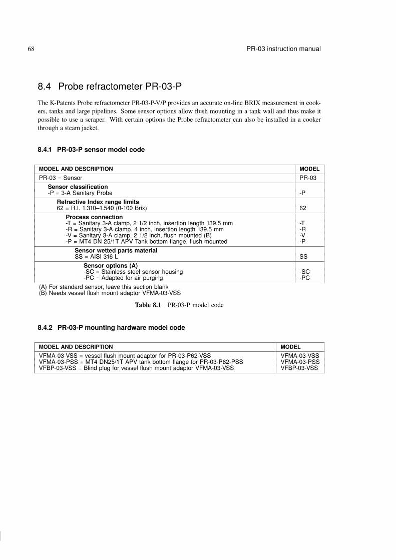
74 74
74 74
68 PR-03 instruction manual
8.4 Probe refractometer PR-03-P
The K-Patents Probe refractometer PR-03-P-V/P provides an accurate on-line BRIX measurement in cook-ers, tanks and large pipelines. Some sensor options allow flush mounting in a tank wall and thus make itpossible to use a scraper. With certain options the Probe refractometer can also be installed in a cookerthrough a steam jacket.
8.4.1 PR-03-P sensor model code
MODEL AND DESCRIPTION MODEL
PR-03 = Sensor PR-03Sensor classification-P = 3-A Sanitary Probe -P
Refractive Index range limits62 = R.I. 1.310–1.540 (0-100 Brix) 62
Process connection-T = Sanitary 3-A clamp, 2 1/2 inch, insertion length 139.5 mm -T-R = Sanitary 3-A clamp, 4 inch, insertion length 139.5 mm -R-V = Sanitary 3-A clamp, 2 1/2 inch, flush mounted (B) -V-P = MT4 DN 25/1T APV Tank bottom flange, flush mounted -P
Sensor wetted parts materialSS = AISI 316 L SS
Sensor options (A)-SC = Stainless steel sensor housing -SC-PC = Adapted for air purging -PC
(A) For standard sensor, leave this section blank(B) Needs vessel flush mount adaptor VFMA-03-VSS
Table 8.1 PR-03-P model code
8.4.2 PR-03-P mounting hardware model code
MODEL AND DESCRIPTION MODEL
VFMA-03-VSS = vessel flush mount adaptor for PR-03-P62-VSS VFMA-03-VSSVFMA-03-PSS = MT4 DN25/1T APV tank bottom flange for PR-03-P62-PSS VFMA-03-PSSVFBP-03-VSS = Blind plug for vessel flush mount adaptor VFMA-03-VSS VFBP-03-VSS

75 75
75 75
8 Sensor specifications and other sensor information 69
8.4.3 PR-03-P specifications
General specifications General system specifications for a PR-03-P refractometer sensorRefractive Index range R.I. 1.3100–1.5400 (corresponds to hot water–100 Brix)Accuracy R.I. ± 0.0002 (corresponds typically to ± 0.1% by weight).
Repeatability and stability correspond to accuracy.Speed of response 1.2 s undampedDamping time constant Selectable up to 5 minProcess temperature -20 ◦C–130 ◦C (-4 ◦F–266 ◦F)Temperature compensation AutomaticAmbient temperature max. 45 ◦C (113 ◦F), min. -20 ◦C (-4 ◦F)Humidity 20–100 %Pollution degree Degree 2Process pressure Sanitary clamp max. 15 bar (200 psi) at 20 ◦C (70 ◦F)/
9 bar (125 psi) at 120 ◦C (250 ◦F)Recommended flow velocity Above 1.5 m/s (5 ft/s)Quality certificate ISO 9001
Sensor Meets the requirements of the 3-A Sanitary Standard 46-02Wetted parts AISI 316L stainless steel, prism gaskets Teflon R©, prism spinelSensor weight 2.4 kg (5.3 lbs)Sensor protection class IP67, Nema 4XProcess connections 2 1/2" Sanitary clamp
4" Sanitary clampMT4 DN 25/1T APV Tank bottom flange
Temperature measurement Built-in Pt-100Image detector 1024 pixel CCD-elementLight source Light emitting diode (LED)Indicating transmitter See Chapter 9Options − External output unit, Section 4.2
− Relay units, Section 4.1− Stainless steel sensor housing

76 76
76 76
70 PR-03 instruction manual
8.4.4 PR-03-P parts lists
Item Pcs. Part No. Description
1 1 PR-9205 2.5"sanitary ferrule1 1 VFMA-03-VSS Vessel flush mount adaptor1 1 VFMA-03-PSS MT4 DN25/1T APV tank bottom flange1 1 VFBP Blind plug for tank bottom flange1 1 PR-4275 4"sanitary ferrule
2 1 PR-9201 2.5"sanitary clamp2 1 PR-9270 4"sanitary clamp
3 1 PR-9202 2.5"sanitary gasket EPDM3 1 PR-9203 2.5"sanitary gasket NBR3 1 PR-9204 2.5"sanitary gasket Teflon R©
3 1 PR-9243 MT4 DN25/1T APV gasket EPDM
3 1 PR-9272 4"3A sanitary gasket EPDM3 1 PR-9273 4"3A sanitary gasket NBR3 1 PR-9274 4"3A sanitary gasket Teflon R©
4 1 PR-9310 PR-03-P-TSS head4 1 PR-9311 PR-03-P-VSS head4 1 PR-9312 PR-03-P-PSS head4 1 PR-9313 PR-03-P-RSS head
5 1 Thermal insulator Teflon R©6 1 Alignment pin7 1 PR-9005 PR-03 base8 6 Screw M5x10 DIN 7991 A29 1 PR-9011 Thermal conductor
Item Pcs. Part No. Description
* 1 PR-9010 Disc spring set10 2 Disc spring11 1 Disc spring holder
12 6 Screw M5x10 DIN912 A213 4 Screw M4x12 DIN14 1 PR-7133 Image digitizer card15 4 Screw M4x8 DIN 912 A216 1 PR-5012 Vee clamp 11-13017 2 Screw M3x8 DIN 91218 1 Bushing holder19 1 Bushing20 2 Screw M4x8 DIN 912 A221 2 Washer M4 DIN 12522 1 PR-5011 O-ring seal 108x323 1 PR-9107 Dryer24 2 Screw M3x16 DIN 912 A425 1 PR-9106 PR-03 connector complete26 1 PR-9301 PR-03 cover27 1 PR-03 sensor label28 4 Screw M3x5 DIN 7380 A4
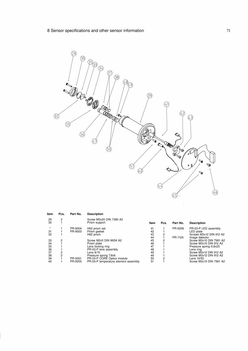
77 77
77 77
8 Sensor specifications and other sensor information 71
Item Pcs. Part No. Description
29 2 Screw M3x20 DIN 7380 A230 1 Prism support
* 1 PR-9004 H62 prism set31 1 PR-9003 Prism gasket32 1 H62 prism
33 2 Screw M2x5 DIN 965A A234 1 Prism plate35 1 Lens locking ring36 1 PR-03-P lens assembly37 2 Lens 8/1038 2 Pressure spring 7.8x639 1 PR-9301 PR-03-P CORE Optics module40 1 PR-9255 PR-03-P temperature element assembly
Item Pcs. Part No. Description
41 1 PR-9256 PR-03-P LED assembly42 1 LED plate43 2 Screws M3x12 DIN 912 A244 1 PR-7125 Image detector45 2 Screw M3x10 DIN 7991 A246 1 Screw M3x10 DIN 912 A247 1 Pressure spring 9.8x2548 1 Lens ring49 1 Screw M3x12 DIN 912 A249 1 Screw M3x12 DIN 912 A250 2 Lens 10/5051 1 Screw M3x10 DIN 7991 A2
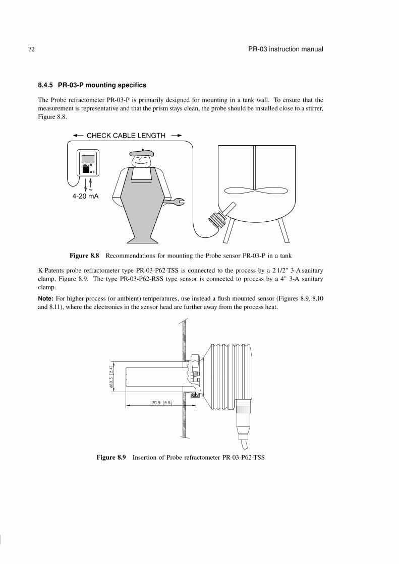
78 78
78 78
72 PR-03 instruction manual
8.4.5 PR-03-P mounting specifics
The Probe refractometer PR-03-P is primarily designed for mounting in a tank wall. To ensure that themeasurement is representative and that the prism stays clean, the probe should be installed close to a stirrer,Figure 8.8.
4-20 mA~
CHECK CABLE LENGTH
Figure 8.8 Recommendations for mounting the Probe sensor PR-03-P in a tank
K-Patents probe refractometer type PR-03-P62-TSS is connected to the process by a 2 1/2" 3-A sanitaryclamp, Figure 8.9. The type PR-03-P62-RSS type sensor is connected to process by a 4" 3-A sanitaryclamp.
Note: For higher process (or ambient) temperatures, use instead a flush mounted sensor (Figures 8.9, 8.10and 8.11), where the electronics in the sensor head are further away from the process heat.
Figure 8.9 Insertion of Probe refractometer PR-03-P62-TSS

79 79
79 79
8 Sensor specifications and other sensor information 73
Figure 8.10 Flush mounted Probe refractometer PR-03-P62-PSS
The refractometer type PR-03-P62-PSS is flush mounted, using a sanitary APV Tank bottom flange, Fig-ure 8.10. The refractometer can be replaced with a blind plug so that the tank can be used even when therefractometer has been removed for service.
The refractometer type PR-03-P62-VSS is specially designed for vessels with a steam jacket, e.g. a jamcooker. In a jam cooker the blade of the scraper should sweep the prism in direct contact. The PR-03-P62-VSS is mounted by means of a vessel flush-mount adaptor VFMA-03-VSS, Figure 8.11.
Figure 8.11 Mounting probe refractometer PR-03-P62-VSSthrough vessel steam jacket with adaptor VFMA-03-VSS

80 80
80 80
74 PR-03 instruction manual
8.4.6 PR-03-P programming specifics
If the optical image appears inverted when using the probe refractometer PR-03-P (see Figure 8.12), con-figure parameter lminv to value 1 by key-in sequence Calibrate / Parameters / Standard RI(25◦C) / Image inversion to turn the picture right way.
A B C D
Slope
TEST: 248.030.2 ºCEndp: 11L): -7.5R(: 3.3HT: 20 ºCHH: 4 %
SCALEDOPTICALIMAGE
Low concentration / No sample
Figure 8.12 Inverted optical image
Note: This image inversion correction is only available in program version 8.5 or higher. When an IT-Ris delivered together with a Probe refractometer sensor, the program version is always compatible with theinverted image.

81 81
81 81
8 Sensor specifications and other sensor information 75
8.5 Compact process refractometer PR-03-D
The K-Patents Compact process refractometer is a compact general industry model for measuring liquidconcentrations in various in-line applications, like chemicals, fibers, plastics, salts and sodium components.Easy to install in smaller pipe lines. Also for applications where special alloys are required.
8.5.1 PR-03-D sensor model code
MODEL AND DESCRIPTION MODEL
PR-03 = Sensor PR-03Sensor classification-D = General purpose -D
Refractive Index range limits62 = R.I. 1.310–1.540 (0-100 Brix) 62
Process connection-L = Sandvik L clamp, 76.1 (A) -L
Sensor wetted parts materialSS = AISI 316 L SSHC = Hastelloy C / ASTM C276 HCTI = Titanium / ASTM B TINI = Nickel 200 NI
Sensor options (B)-SC = Stainless steel sensor housing -SC-PC = Adapted for Exproof by purging (C) -PC
(A) Includes counter ferrule for Sandvik 76.1(B) For standard sensor without option, leave this section blank(C) Available with -SC code only, including 5 meters sensor cable, PR-8400-005
Example: Sensor: PR-03-D62-LSS
8.5.2 PR-03-D mounting hardware model code
MODEL AND DESCRIPTION MODEL
PFC = Pipe flow cell PFCSensor connection-L = Sandvik L clamp -L
Construction materialSS = AISI 316 SS
Process connection-A = ANSI 150 psi -A
Pipe section diameter10 = 25 mm (1 inch) 10
For line sizes 76 mm (2 1/2 inch) or bigger use standard process connections.

82 82
82 82
76 PR-03 instruction manual
8.5.3 PR-03-D specifications
General specifications General system specifications for a PR-03-D refractometer sensorRefractive Index range R.I. 1.3100–1.5400 (corresponds to hot water–100 Conc% b.w.)Accuracy R.I. ± 0.0002 (corresponds typically to ± 0.1% by weight).
Repeatability and stability correspond to accuracy.Speed of response 1.2 s undampedDamping time constant Selectable up to 5 minProcess temperature -20 ◦C–130 ◦C (-4 ◦F–266 ◦F)Temperature compensation AutomaticAmbient temperature max. 45 ◦C (113 ◦F), min. -20 ◦C (-4 ◦F)Humidity 20–100 %Pollution degree Degree 2Process pressure max. 15 bar (200 psi) at 20 ◦C (70 ◦F)/
9 bar (125 psi) at 120 ◦C (250 ◦F)Recommended flow velocity Above 1.5 m/s (5 ft/s)Quality certificate ISO 9001
SensorWetted parts AISI 316L stainless steel, prism gaskets Teflon R©, prism spinelOptional wetted parts Hastelloy C/ASTM C276, Titanium/ASTM B 348 GR2, Nickel 200Sensor weight 2 kg (4.4 lbs)Sensor protection class IP67, Nema 4XProcess connection Sandvik L clamp 76.1 mm (2 1/2")Temperature measurement Built-in Pt-100Image detector 1024 pixel CCD-elementLight source Light emitting diode (LED)Indicating transmitter See Chapter 9Options − External output unit, Section 4.2
− Relay units for prism wash/alarm, Section 4.1− Stainless steel sensor housing
1.30 1.35 1.40 1.45 1.50 1.55 1.60
R.I.
400 10 20 30 50 60 70 80 CONC%
D62
Figure 8.13 Compact process refractometer PR-03-D rangeability

83 83
83 83
8 Sensor specifications and other sensor information 77
8.5.4 PR-03-D parts lists
Item Pcs. Part No. Description1 1 PR-9280-SS Sandvik ferrule 76.1 AISI 316L1 1 PR-9280-HC Sandvik ferrule 76.1 Hastelloy1 1 PR-9280-TI Sandvik ferrule 76.1 Titanium1 1 PR-9280-NI Sandvik ferrule 76.1 Nickel2 1 PR-9282 Sandvik clamp FCLC-76.1 AISI 3043 1 PR-9281 Sandvik O-ring FCLG-T-76.1 Teflonregistered
4 1 PR-9009 PR-03 Sandvik 76.1 head5 1 Thermal insulator Teflon R©6 1 Alignment pin7 1 PR-9005 PR-03 base8 6 Screw M5x10 DIN 7991 A29 1 PR-9011 Thermal conductor* 1 PR-9010 Disc spring set
10 2 Disc spring11 1 Disc spring holder12 6 Screw M5x10 DIN 912 A213 4 Screw M4x12 DIN 91214 1 PR-7133 Image digitizer15 4 Screw M4x8 DIN 912 A216 1 PR-9001 CORE optics module17 1 PR-5012 Vee clamp 11-130
Item Pcs. Part No. Description
18 2 Screw M3x8 DIN 91219 1 Bushing holder20 1 Bushing21 1 PR-7125 Image detector card22 2 Screw M4x8 DIN 912 A223 2 Washer M4 DIN 12524 1 PR-5011 O-ring seal 108x325 1 PR-9107 Dryer26 2 Screw M3x16 DIN 912 A427 1 PR-9106 PR-03 connector complete28 1 PR-9110 PR-03 sensor cover29 1 PR-03 sensor label30 4 Screw M3x5 DIN 7380 A4

84 84
84 84
78 PR-03 instruction manual
Item Pcs. Part No. Description
29 2 Screw M3x10 DIN 7380 A230 1 Prism support30 1 Prism support H6431 1 PR-9003 Prism gasket (PTFE)32 1 PR-9004 H62 prism set (Spinel)33 2 Screw M2x5 DIN 965A A234 1 Prism plate35 1 Lens locking ring36 1 Lens37 1 Lens 8/1038 2 Pressure spring 7.8x639 1 PR-9001 CORE optics module40 1 PR-9250 PR-03 temperature element assembly
Item Pcs. Part No. Description
41 1 PR-9251 PR-03 LED assembly42 1 LED plate43 2 Screws M3x4 DIN 91244 1 PR-7125 Image detector card45 2 Screw M3x10 DIN 7991 A246 1 Screw M3x10 DIN 912 A2

85 85
85 85
8 Sensor specifications and other sensor information 79
8.5.5 PR-03-D mounting specifics
In pipes with the nominal size 2.5" (76.1 mm) or larger, the Compact process refractometer PR-03-D sensoris mounted with a Sandvik-L 76.1 clamp, Figure 8.14. For smaller pipes, the sensor has to be mounted withthe PFC Pipe Flow cell, Figure 8.15.
Figure 8.14 Mounting PR-03-D in pipelines with diameter 2.5" (76.1 mm) or larger

86 86
86 86
80 PR-03 instruction manual
Figure 8.15 Mounting PR-03-D in pipelines with diameter less than 2.5" (76.1 mm)

87 87
87 87
8 Sensor specifications and other sensor information 81
8.6 Process refractometer PR-03-M
K-Patents Process refractometer PR-03-M is de-signed for use in chemically aggressive solutionsand ultra-pure fine chemical processes. It has abuilt-in flow cell designed to keep all metal andother easily corroding parts from coming into con-tact with the process liquid. All the wetted partsare made of non-metallic materials, either PTFE(Teflon R©) or PVDF (Kynar R©), and thus thePR-03-M sensor withstands corrosion very well.
The flow cell (N) and the sapphire plate (L) arefixed to the stainless steel sensor with four screws.The flow cell (N) is sealed by a Kalrez O-ring(M). The flow cell prevents any leakage reachingthe metal parts, because there is a circular leakagechamber behind the O-ring (M). The chamber con-nects to a check port (O), which has a 1/8" femalethread connection.
Figure 8.16 PR-03-M sensor
8.6.1 PR-03-M sensor model code
MODEL AND DESCRIPTION MODEL
PR-03 = Sensor PR-03Sensor classification-M = Aggressive medium adapter -M
Refractive Index range limits62 = 1.310–1.540 R.I. (0.100 Conc% b.w.), Spinel prism 6274 = 1.260–1.500 R.I., sapphire prism 74
Process line connection-R = Thread (G 1/2 inch) -R-N = Thread (1/2 inch NPT female) -N
Line size connection diameter-050 = 1/2 inch (flow volume 2-8 l/min (0.5-2.1 GPM)) -050
Flow cell wetted parts material-PV = Kynar R© (PVDF=Polyvinylidenefluoride) -PV-TF = Teflon R© (PTFE=Polytetrafluoroethylene) -TF
Sensor cover-SC = Stainless Steel sensor housing -SC
Sensor options-PC = adapted for Exproof by purging (A) -PC
(A) including 5 meter sensor cable, PR-8400-005
Example: Sensor: PR-03-M62-R-050-TF-SC

88 88
88 88
82 PR-03 instruction manual
8.6.2 PR-03-M specifications
General specifications General system specifications for a PR-03-M refractometer sensorRefractive Index range, standard R.I. 1.3100–1.5400 (corresponds to hot water–100 Brix) with
spinel prismRefractive Index range R.I. 1.2600–1.5000 with sapphire prismRefractive Index range R.I. 1.3900–1.6200 with YAG prismAccuracy R.I. ± 0.0002 (corresponds typically to ± 0.1% by weight).
Repeatability and stability correspond to accuracy.Speed of response 1.2 s undampedDamping time constant Selectable up to 5 minProcess temperature -20 ◦C–130 ◦C (-4 ◦F–212 ◦F)Temperature compensation AutomaticAmbient temperature max. 45 ◦C (113 ◦F), min. -20 ◦C (-4 ◦F)Humidity 20–100 %Pollution degree Degree 2Process pressure max 5 bar (72.5 psi)Recommended flow velocity 2–40 l/min (0.5–10.6 GPM)Protected by the following US Patent Patent No. US6067151
SensorWetted parts, standard Teflon R© or Kynar R© PVDF, prism gaskets Teflon R©, prism spinel,
O-ring Kalrez, adaptor sapphireWetted parts, option prism sapphire or YAGSensor weight 5.5 kg (12.1 lbs)Sensor protection class IP67, Nema 4XProcess connection Thread G1/2" (F)Temperature measurement Built-in Pt-100Image detector 1024 pixel CCD-elementLight source Light emitting diode (LED)Sensor housing AISI 316L stainless steel sensor coverExproof Exproof by purgingIndicating transmitter see page See Chapter 9Options − External output unit, Section 4.2
− Relay units for alarm, Section 4.1
1.301.25 1.35 1.40 1.45 1.50 1.55 1.60 1.65
R.I.
400 10 20 30 50 60 70 80 BRIX
M62
M74
Figure 8.17 Process refractometer PR-03-M rangeability

89 89
89 89
8 Sensor specifications and other sensor information 83
8.6.3 PR-03-M parts lists
Item Pcs. Part No. Description
1 4 Screw M5x60 DIN 7991 A42 1 PR-03-M endplate3 1 PR-9120 PR-03-M-PV-R05 flow cell (PVDF)3 1 PR-9121 PR-03-M-TF-R05 flow cell (PTFE)4 1 PR-9240 O-ring seal 19.2 x 3 Kalrez 40795 6 Screw M4 x 20 DIN 7991 A46 1 PR-03-M Headring (PVDF)7 1 PR-9112 O-ring seal 30.3 x 2.4 FPM8 1 PR-9122 Sapphire plate for PR-03-M9 1 PR-9113 O-ring seal 37.3 x 3 FPM10 1 PR-9100 Sensor support11 1 PR-9102 PR-03-M head12 1 Thermal insulator (Teflon R©)13 1 Alignment pin14 1 PR-9005 PR-03 base15 6 Screw M5x10 DIN 7991 A216 1 PR-9001 CORE optics module16 1 PR-9101 CORE 74 optics module17 1 PR-9011 Thermal conductor
* 1 PR-9010 Disc spring set18 2 Disc spring19 1 Disc spring holder20 6 Screw M5x10 DIN 912 A221 1 PR-7125 Image detector card22 4 Screw M4x12 DIN23 1 PR-7133 Image digitizer24 4 Screw M4x8 DIN 912 A225 1 PR-5012 Vee clamp 11-130
Item Pcs. Part No. Description
26 2 Screw M3x16 DIN 912 A427 1 Bushing holder28 1 Bushing29 1 PR-5011 O-ring seal 108x330 1 PR-9107 Dryer31 2 Screw M4x8 DIN 912 A232 2 Washer M4 DIN 12533 2 Screw M3x8 DIN 91234 1 PR-9106 PR-03 connetor complete35 1 PR-9110 PR-03 cover36 1 PR-03 sensor label37 4 Screw M3x5 DIN A4

90 90
90 90
84 PR-03 instruction manual
Item Pcs. Part No. Description
38 2 Screw M3x10 DIN 7380 A239 1 Prism support39 1 Prism support H64* 1 PR-9004 H62 prism set (Spinel)
40 1 PR-9003 Prism gasket (PTFE)41 1 H62 prism (Spinel)* 1 PR-9104 H74 prism set (Sapphire)
40 1 PR-9003 Prism gasket (PTFE)41 1 H74 prism (Sapphire)42 2 Screw M2x5 DIN 965A A243 1 Prism plate44 1 Lens locking ring45 1 Lens46 2 Lens 8/1047 2 Pressure spring 7.8x648 1 PR-9250 PR-03 temperature element assembly
Item Pcs. Part No. Description
49 1 PR-9251 PR-03 LED assembly50 1 LED plate51 2 Screws M3x4 DIN 91221 1 PR-7125 Image detector card52 2 Screw M3x10 DIN 7991 A253 1 Screw M3x10 DIN 912 A2

91 91
91 91
8 Sensor specifications and other sensor information 85
8.6.4 PR-03-M mounting specifics
K-Patents Process refractometer PR-03-M is connected to the process by a G1/2" female or a 1/2" NPTprocess connection, Figure 8.18.
Figure 8.18 G1/2" female process connection (mm [in])
8.7 Valve body refractometer PR-03-W
The Valve body refractometer PR-03-Wis a heavy-duty instrument designed forchemically aggressive liquids and ultra-pure fine chemicals in large-scale pro-duction and in large pipelines. The ma-terials and design of the sensor are simi-lar to the Process refractometer PR-03-M, but the valve body makes it possi-ble to fit this refractometer into 50, 80or 100 mm (2", 3" or 4") pipelines.
The valve body material is graphite castiron lined with 3 mm PFA (Fluorinatedethylene propylene) fluoroplastic. Thecast iron provides a solid mechanicalbase and the PFA lining ensures thechemical resistance.
3
Figure 3. Process Refractometer PR-03-W sensor and Saunders body valve flow cell (3” pipe): Dimensions.
TECHNICAL DESCRIPTIONThe K-Patents Process Refractometer PR-03-W isdelivered with a Saunders valve body flow cell. Theflow cell can be mounted either in a vertical orhorizontal pipe.
The valve body material is graphite cast iron linedwith 3mm PFA (Fluorinated ethylene propylene)fluoroplastic. The Cast iron provides a solidmechanical base and the PFA-lining ensures thechemical resistance.
The sensor wetted parts materials are Spinel orsapphire (prism), PTFE or PELD (prism gasket),sapphire plate, PVDF or PTFE®Teflon and PFA(flow cell lining material). The K-Patents PR-03-Whas a stainless steel sensor cover.
The measurement surface, the prism, is flushmounted into the surface of the sensor probe tip.The prism is integral part of the CORE-optics(Compact Optical Rigid Element) module, which isspringloaded against the prism gasket. A sapphireplate has conical sealing surface against theCORE-optics and it lies on the stainless steelsensor head.
The flow cell is sealed with a Kalrez O-ring. Thelight source is a light emitting diode (LED). Thedigital image detecting sensor is a CCD-camera,which consists of 1024 photocells.
The CCD-camera is protected from the processheat by two isolation parts. Excess heat istransferred with a heat conductor to the sensorcover, which is air cooled (air cooling fins).
For automatic temperature compensation, the sensortip contains a Pt-100 process temperature probe. Theresponse time is very fast (τ(1/2) = 6 s), which isnecessary for a real-time concentrationmeasurement. The microprocessor systemlinearizes the concentration reading, and performsautomatic temperature compensation. Exactprecision is achieved due to the fact that thecompensation is calculated mathematically and notusing a conversion table.
The measurement is completely digital, as a serialsignal is used to send the raw measurement data(optical image data and temperature) from thesensor to the Indicating Transmitter. Themicroprocessor system displays the optical imageand implements an image analyzing algorithm.
The Indicating Transmitter contains a power supply,a microprocessor system and a front panel with aLiquid Crystal Display (LCD) and a Keyboard.
The output signals are a 4-20 mA concentrationsignal and a Serial output signal, RS232 or RS485alternatively. There are also two built-in signalrelays, which can be configured to relay functions,e.g. for alarm purposes in a control system.
The Indicating Transmitter also accepts 4 inputswitch closures for signal HOLD or scale selection.A serial bus connects the Indicating Transmitter tothe external units such as Relay Unit or ExternalOutput Unit. Unauthorized access can beprevented: Knockout padlock provisions areincluded in both cover latches.
PTFE or PVDF wetted parts
Sapphire plateO-ring (Kalrez)
Prism
Flow cell adapter (AISI 316L)
Graphite cast iron
Saunders valve body flow cell
FLO
W
PR-03-W Sensor
Figure 8.19 PR-03-W sensor
The sensor itself is built just like the PR-03-M sensor (see Section 8.6) and it is fixed to the valve body inthe same way, with a sapphire plate and a Kalrez O-ring to keep all the metallic parts away from the processliquid.

92 92
92 92
86 PR-03 instruction manual
8.7.1 PR-03-W sensor model code
MODEL AND DESCRIPTION MODEL
PR-03 = Sensor PR-03Sensor classification-W = Aggressive medium valve body flow cell -W
Refractive Index range limits62 = 1.310–1.540 R.I., Spinel prism (0-100 Conc% b.w.) 6274 = 1.260–1.500 R.I., sapphire prism 74
Sensor wetted parts material-PV = Kynar R© (PVDF=Polyvinylidenefluoride) -PV-TF = Teflon R© (PTFE=Polytetrafluoroethylene) -TF
Sensor/diaphragm valve body connection4 = Adapter for 4 inch/DN 100 valve body 43 = Adapter for 3 inch/DN 80 valve body 32 = Adapter for 2 inch/DN 50 valve body 2
Sensor cover-SC = stainless steel sensor housing -SC
Sensor classification-GP = General purpose, Nema 4X -GP-PC = Adapted for Exproof by purging(A) -PC
(A) Including 5 meter sensor cable, PR-8400-005
SAUNDERS VALVE BODY FOR SENSOR PR-03-W MODEL
SVB = Saunders valve body SVBProcess line connection-A040 = ANSI flange 4 inch 150 lbs -A040-A030 = ANSI flange 3 inch 150 lbs -A030-A020 = ANSI flange 2 inch 150 lbs -A020-D100 = DIN flange DN 100 PN 16 -D100-D080 = DIN flange DN 80 PN 16 -D080-D050 = DIN flange DN 50 PN 16 -D050
Valve body material-GC = Graphite cast iron -GC
Valve body lining material-PFA = PFA (= Fluorinated ethylene propylene) -PFA

93 93
93 93
8 Sensor specifications and other sensor information 87
8.7.2 PR-03-W specifications
General specifications General system specifications for a PR-03-W refractometer sensorRefractive index range, standard R.I. 1.3100–1.5400 (corresponds to hot water–100 Conc% b.w.) with
spinel prismRefractive index range, option R.I. 1.2600–1.5000 with sapphire prismAccuracy R.I. ± 0.0002 (corresponds typically to ± 0.1% by weight).
Repeatability and stability correspond to accuracy.Speed of response 1.2 s undampedDamping time constant Selectable up to 5 minProcess temperature -20 ◦C–100 ◦C (-4 ◦F–212 ◦F)Temperature compensation AutomaticAmbient temperature max. 45 ◦C (113 ◦F), min. -20 ◦C (-4 ◦F)Humidity 20–100 %Pollution degree Degree 2Process pressure max. 10 bar (145 psi)Recommended flow velocity 1.5–6 m/sProtected by US Patent No. US6067151, German Patent No. DE19855218
SensorWetted parts, standard Teflon R© PTFE, prism gasket Teflon R© PTFE, prism spinel or sapphire,
O-ring Kalrez, adaptor sapphireSensor weight With 2” Saunders body 15 kg (33 lbs)/3” Saunders body 26 kg
(57 lbs)/4” Saunders body 33 kg (73 lbs)Sensor protection class IP67, Nema 4XProcess connection With PFA (Fluorinated ethylene propylene) lined Saunders valve body
2", 3" or 4"Temperature measurement Built-in Pt-100Image detector 1024 pixel CCD-elementLight source Light emitting diode (LED)Sensor housing AISI 316L stainless steel coverExproof Exproof by purging
Saunders valve bodyValve body material Graphite cast ironValve body lining material PFA (Fluorinated ethylene propylene)Process connection ANSI flange 4 inch 150 lbs / ANSI flange 3 inch 150 lbs /
ANSI flange 2 inch 150 lbs / DIN flange DN 100 PN 16 /DIN flange DN 80 PN 16 / DIN flange DN 50 PN 16
Indicating transmitter See Chapter 9Options − External output unit, Section 4.2
− Relay units for alarm, Section 4.1

94 94
94 94
88 PR-03 instruction manual
8.7.3 PR-03-W parts lists
Item Pcs. Part No. Description
1 4 Screw M5x60 DIN 7991 A43 1 Saunders valve body PFA lining ANSI 2“/DIN 503 1 Saunders valve body PFA lining ANSI 3“/DIN 803 1 Saunders valve body PFA lining ANSI 4“/DIN 1004 1 PR-9240 O-ring seal 19.2 x 3 Kalrez 40795 6 Screw M4 x 20 DIN 7991 A 46 1 Spacer7 1 PR-9112 O-ring seal 30.3 x 2.4 FPM8 1 PR-9122 Sapphire plate for PR-03-M9 1 PR-9113 O-ring seal 37.3 x 3 FPM10 1 PR-03-M Headring (PVDF)11 1 PR-9102 PR-03-W head12 1 Thermal insulator Teflon R©13 1 Alignment pin14 1 PR-9005-SC PR-03 base SS15 6 Screw M5x10 DIN 7991 A216 1 PR-9011 Thermal conductor
* 1 PR-9010 Disc spring set17 2 Disc spring18 1 Disc spring holder
Item Pcs. Part No. Description
19 6 Screw M5x10 DIN912 A220 4 Screw M4x12 DIN21 1 PR-7133 Image digitizer22 4 Screw M4x8 DIN 912 A223 1 PR-5012 Vee clamp 11-13024 2 Screw M3x8 DIN 91225 1 Bushing holder26 1 Bushing27 2 Screw M4x8 DIN 12528 2 Washer M4 DIN 912 A229 1 PR-5011 O-ring seal 108x330 1 PR-9107 Dryer31 2 Screw M3x16 DIN 912 A232 1 PR-9106 PR-03 connector complete33 1 PR-9110-SC PR-03 cover34 1 PR-03 sensor label35 4 Screw M3x5 DIN 7380 A439 1 PR-9001 CORE optics module39 1 PR-9101 CORE 74 optics module44 1 PR-7125 Image detector card

95 95
95 95
8 Sensor specifications and other sensor information 89
8.7.4 PR-03-W mounting specifics
PR-03-W Saunders valve body flow cell can be mounted either vertically or horizontally. Special sensorsupport is not needed as the valve body (piping) supports the sensor. Either way sensor cover should alwaysbe horizontal to avoid sedimentation or gas/air pocket on the prism. Also installation after pump, beforevalve and low installation point will reduce risk of air/gas pocket. Recommended flow velocity is 1.5–6m/s(6–20ft/s).

96 96
96 96
90 PR-03 instruction manual
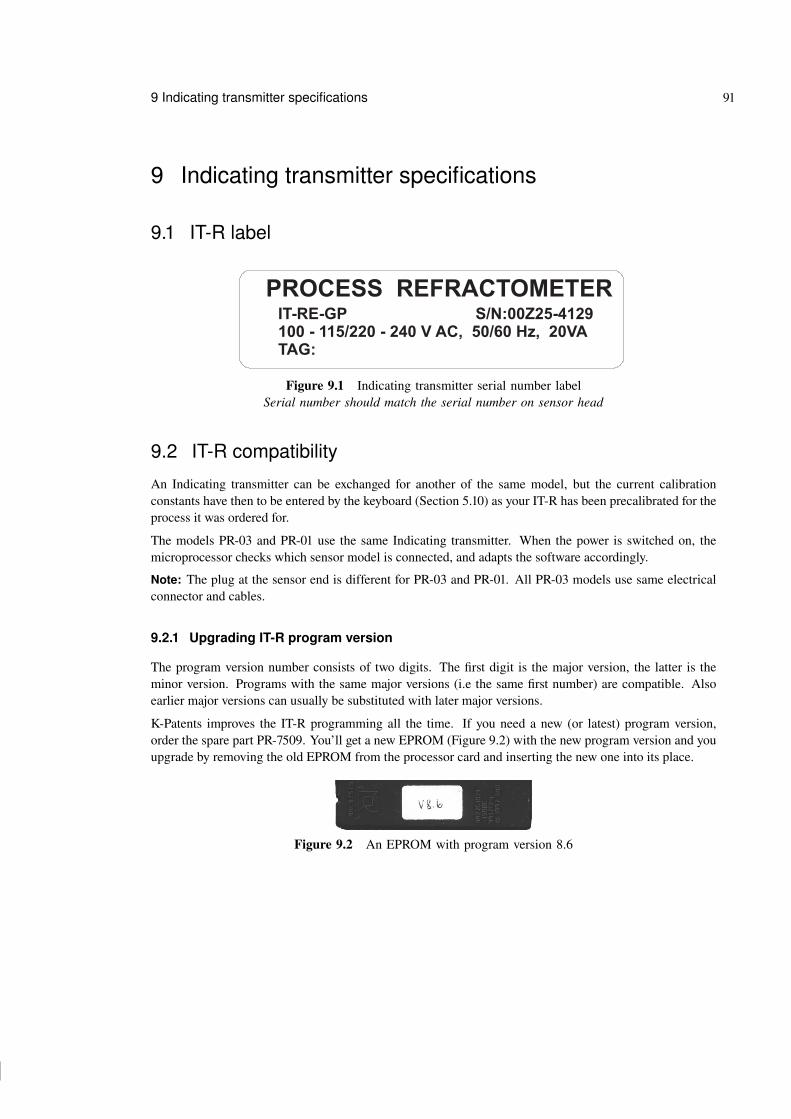
97 97
97 97
9 Indicating transmitter specifications 91
9 Indicating transmitter specifications
9.1 IT-R label
PROCESS REFRACTOMETERIT-RE-GP S/N:00Z25-4129
100 - 115/220 - 240 V AC, 50/60 Hz, 20VA
TAG:
Figure 9.1 Indicating transmitter serial number labelSerial number should match the serial number on sensor head
9.2 IT-R compatibility
An Indicating transmitter can be exchanged for another of the same model, but the current calibrationconstants have then to be entered by the keyboard (Section 5.10) as your IT-R has been precalibrated for theprocess it was ordered for.
The models PR-03 and PR-01 use the same Indicating transmitter. When the power is switched on, themicroprocessor checks which sensor model is connected, and adapts the software accordingly.
Note: The plug at the sensor end is different for PR-03 and PR-01. All PR-03 models use same electricalconnector and cables.
9.2.1 Upgrading IT-R program version
The program version number consists of two digits. The first digit is the major version, the latter is theminor version. Programs with the same major versions (i.e the same first number) are compatible. Alsoearlier major versions can usually be substituted with later major versions.
K-Patents improves the IT-R programming all the time. If you need a new (or latest) program version,order the spare part PR-7509. You’ll get a new EPROM (Figure 9.2) with the new program version and youupgrade by removing the old EPROM from the processor card and inserting the new one into its place.
Figure 9.2 An EPROM with program version 8.6

98 98
98 98
92 PR-03 instruction manual
1. Important: Before you upgrade any program versions, write down allcurrent parameters from the calibration screen of the Indicating trans-mitter. Also remember to take note of the wash and relay parameters.
2. Power off and open the front panel of the IT-R.
3. Unscrew the cover on the inside of the front panel. Unplug the cablefrom the Power supply card to the front panel and remove the cover tosee the Processor card.
4. Carefully remove the old EPROM (Figure 9.3)and insert the new one.
5. Place the cover over the Processor card, screw it on and reconnect thecable from the Power supply card to the front panel. Close the frontpanel.
6. Press the ENTER button and at the same time switch on the power. Youwill now enter the Factory Calibration mode.
7. Press 1 for Default settings. Make sure that all pre-upgrade parametershave been written down.
EPROM
Figure 9.3 Locationof the EPROM onthe Processor card
8. Press ENTER to load default parameters and press RESET twice to exit from the Factory calibration.
9. Switch power off. Switch power back on.
10. Enter all the pre-upgrade parameters (wash and relay parameters included) into the transmitter.
Note: The image inversion needed with the Probe refractometer PR-03-P sensor was first implemented inthe main program version 8.6. Program version 8.5 can be updated to manage the image inversion. Versionsbelow 8.5 are not compatible with the Probe refractometer PR-03-P sensor.
9.3 Model code
9.3.1 IT-R model code
MODEL AND DESCRIPTION MODEL
IT-R = Indicating Transmitter IT-RCable connectionU = 1/2 inch NPT-type conduit hubs UE = BF11/PG11 cable glands (with -GP option only) EM = M20x1.5 metric cable glands (with -GP option only) M
Electrical classification-GP = General purpose -GP-CS = CSA appr. for use in general purpose (ordinary) locations -CS
Transmitter options-WR = Relay unit, 2 relays -WR

99 99
99 99
9 Indicating transmitter specifications 93
9.3.2 Interconnecting cable model code
PART NUMBER AND DESCRIPTION PART NO.
PR-8300 = Interconnecting cable between transmitter and sensor PR-8300PR-8040 = Interconnecting cable (-PC sensor option only) PR-8040
(for connection between transmitter and disconnecting unit)Cable length-010 = 10 meters (33 feet), standard length -010-_ _ _ = Specify cable length in meters with 10 meter increments. -_ _ _
Maximum length is 100 meters (330 feet)
9.4 IT-R Specifications
Indicating transmitterTransmitter protection class: Enclosure IP66, Nema 4XIndicating transmitter weight: 4.5 kgDisplay: 256 x 128 pixels graphic liquid crystal display (LCD)Current output: 4–20 mA/0–20 mA, max. load 1000 Ohm, galvanic isolation
1500 V DC or AC (peak), built-in hold function during prismwash
Serial output: RS485/RS232, galvanic isolation 500 V CD or AC (peak)Power: 100–115 V/220–240 V, 50/60 Hz, 20 VAAlarms: Two built-in signal relays, max 24 V, 500 mA, DC/ACApproved environmental conditionsAmbient temperature: max. 50 ◦C (122 ◦F), min. 0 ◦C (32 ◦F)Humidity: 20–100 %Overvoltage category: Category IIPollution degree: Degree 2Interconnecting cable Shielded cable, 2 twisted pairs with individual shields, 0.5 mm2
Digital transmission according RS485Interconnecting cable length: Standard 10 m (33 ft), max. 100 m (330 ft)Cable fittings options: European cable glands or US conduit hubs
9.4.1 Fuses
The following 250 V fuses according to IEC 60127 are printed on circuit board PR-7030:
Fuse F1, F2 : 5 x 20 mm, T1A (slow) AC Main power protects electronics againstwrong primary voltage
Fuse F3 : 5 x 20 mm, T63 mA (slow) 4-20 mA output protectionFuse F4 : 5 x 20 mm, T2A (slow) Secondary main fuseFuse F5 : 5 x 20 mm, T500 mA (slow) Sensor power protectionFuse F6 : 5 x 20 mm, T500 mA (slow) Serial bus protectionFuse F7 : 5 x 20 mm, T1A (slow) Processor card protection
Important: For a CSA-Certified instrument use only CSA-Certified fuses F1, F2, F4-F7.

100 100
100 100
94 PR-03 instruction manual
9.4.2 Serial output specifications
The output measurement results are sent in ASCII code (ISO 646, CCITT V.3) using a standard asyn-chronous interface. The output consists of fixed-length text records. A record is sent for every measurementinterval (1200 ms).
The RS-232 output conforms to the EIA RS-232-C and CCITT V.24 standards. The signals are availableat plug terminal P3 on the IT-R’s processor card. A cable diagram for computer connection is shown inFigure 9.4, pin numbers for a 9-pin D-shell connector (standard female COM connector) are given (pinnumbers for a 25-pin connector and for a modem connection cable are available at K-Patents on request).
Note: RS-232-C specifies a maximum cable length of 15 m.
3
7
1
2
8
4
5
6
Transmit data
Receive data
Signal ground
INDICATING TRANSMITTER
Request to send
Clear to send
Data set ready
Data carrier detect
Data terminal ready
SDRD SGND
SGND DAT- DAT+
D9
DTE
Figure 9.4 Connections for a RS-232 cable for COM connection on a PC
The character structure of the data sent via the serial output interface conforms to the ISO 1177 standard. Itis compatible with the ’RS-232’ interfaces (COM port and terminal software) of most personal computers.
The character parameters are configuration selectable:
− speed 1200 to 9600 bits/s− parity odd, even or none− stop bits 1 or 2− flow control hardware, XON / XOFF or none.
The factory setting 9600,even,1,none is normally the best option for computer connections.
9.4.3 Password
The Change parameters display can be optionally locked behind a password function. When thepassword function is activated, entry to this screen is not allowed without a correct password, see Figure 9.5.
The password function can be activated or deactivated by selecting:Calibrate / Parameters / Password / Active orCalibrate / Parameters / Password / Inactive.
The password for K-Patents PR-03 is printed on the front page of this manual.

101 101
101 101
9 Indicating transmitter specifications 95
9.5 IT-R Parts list
Item Pcs. Part No. Description Item Pcs. Part No. Description
1 1 Enclosure 3 1 Front panel1.1 4 Mounting feet 3.1 2 Hinge1.2 4 Screws 10-32 pan head 3.2 4 Screws DIN 912 M3 x 101.3 4 Screws 10-32 pan head 3.3 1 PR-7315 Keyboard1.4 4 Cable glands PG 11 (European) 3.4 6 Screws DIN 799/DIN 965 M3 x 121.5 4 Conduit hubs 1/2" NPT-Type ST-1 (US) 3.5 2 Ferrule 3.0 x 8 x 31.5 4 Conduit hubs M20x1.5 (European) 3.6 2 Stand-off M3 x 102. 1 Frame plate 3.7 4 Stand-off M3 x 152.1 1 Screw DIN 912 M5 x 50 Zn 3.8 4 DIN 912 M3 x 82.2 1 Washer DIN 9021 5.2 x 18 Zn 3.9 2 Nut DIN 934 M32.3 1 Washer DIN 9021 5.2 x 18 Zn 3.10 2 Stand-off M3 x 152.4 1 Nut DIN M5 Nyloc N 3.11 2 Nut DIN 934 M32.5 1 PR-7301 Transformer 3.12 2 Ferrule 5 x 8 x 32.6 4 Nuts DIN 934 M4 3.13 2 Screw DIN 912 M3 x 102.7 4 Stand-off M4 x 15 3.14 2 Locking screw2.8 4 Screws DIN 912 M4 x 8 3.15 2 Locking washer2.9 1 PR-7030 Power supply card 3.16 1 PR-7305 Display2.10 1 Switch actuator 3.17 1 PR-7019 Display cable2.11 1 PR-7028 Ribbon cable 3.18 1 PR-7020 Display controller card
PR-7029 Fuse set 3.19 1 PR-7010 Processor card(10 Fuses: 4 x 1A, 1 x 63 mA, 2.2A, 3 x 0.5 A) 3.20 1 PR-7009 Program memory
3.21 1 Cover
4 1 PR-8000-... Sensor cable

102 102
102 102
96 PR-03 instruction manual
9.6 Command selection tree
AA
A
A
A
AA-D
4 3 3 45 7
3 265
B
3 2A
C D
D
A421 6
187 9
42
1
1242
C
3
1
310
3 4A-B
31 1 A A2B
A B
41
SLO
PE
SC
ALE
DIM
AG
EO
PT
ICA
LIM
AG
E
STA
RT
PR
ISM
WA
SH
DIA
GN
OS
TIC
S
TE
MP
BIA
S
SW
ITC
HE
S
WA
SH
INT
ER
VA
L
R1
SQ
UA
RE
DA
MP
ING
TIM
E
TN
M
TE
MP
TC
AD
JU
ST
RE
CO
VE
RY
TIM
E
R1
GA
INS
TA
ND
AR
DR
I(2
5°C
)
TE
MP
ER
AT
UR
EP
AR
AM
ET
ER
S
SE
RIA
LO
UT
PU
T
DIS
PLA
YD
EC
IMA
LS
CO
NC
(R.I.)
SY
ST
EM
CO
NF
IGU
RA
TIO
N
SE
NS
OR
HE
AD
DIS
PLA
Y
No
te!
,re
fer
to(C
ha
pte
r3
),w
he
rea
sre
fers
to(C
ha
pte
r4
).R
ela
y1
Re
lay
2b
uil
t-in
sig
na
lre
lay
sre
lay
un
ite
xte
rna
lre
lay
un
it
OP
TIC
AL
IMA
GE
CU
BE
GA
IN
AC
TIV
E
TE
MP
CO
EF
F
DIV
ER
TC
ON
TR
OL
DIV
ER
TC
ON
TR
OL
LA
NG
UA
GE
PA
SS
WO
RD
HIG
HT
EM
PLIM
IT
WA
SH
TIM
E
PR
ISM
WA
SH
R1
BIA
S
EX
TE
RN
AL
OU
TP
UT
OU
TP
UT
SIG
NA
LS
RE
LA
YS
CA
LIB
RA
TE
SW
ITC
HIN
PU
TS
UN
IT
SQ
UA
RE
BIA
S
INA
CT
IVE
RE
LA
YU
NIT
RE
LA
YA
LA
RM
DE
LA
Y
RE
LA
Y1
OR
RE
LA
Y2
TE
MP
C1
PR
EC
ON
DIT
ION
TIM
E
CU
RR
EN
TO
UT
PU
T
RE
MO
VE
FR
OM
DIS
PLA
Y
PA
RA
ME
TE
RS
TE
MP
C0
DIS
AB
LE
HIG
HTE
MP
LIM
IT
SE
TP
AS
SW
OR
D
WA
SH
CH
EC
K
WA
SH
ST
OP
R1
CU
BE
SW
ITC
HS
ELE
CT
ED
SC
ALE
S
DIS
PLA
YE
DT
EM
PU
NIT
NO
RM
AL
DIS
PL
AY
PA
SS
WO
RD
LIM
IT
CBA
WA
SH
TIM
ES
SW
ITC
HC
ON
FIG
UR
AT
ION
RE
LA
YC
ON
FIG
UR
AT
ION
SM
AR
TW
AS
HC
SQ
UA
RE
TE
MP
CO
CO
NC
TC
AD
JU
ST
98542 631
ICA
L0
RA
NG
E
SP
AN
ICA
L1
HO
LD
FU
NC
TIO
N
ZE
RO
9IM
AG
EIN
VE
RS
ION
Figure 9.5 The IT-R selection tree

103 103
103 103
9 Indicating transmitter specifications 97
9.7 Display messages
Message Cause and action
NORMAL OPERATION No faults.
DIVERT CONTROL Not used with PR-03.If this message occurs, deactivate with the commandCalibrate / Parameters / Divert control /Divert Control.
REMOVED FROM DIVERT CONTROL Not used with PR-03
RETRYING WASH The prism wash failed the wash check (Section 5.9.4). The(Sanitary refractometer PR-03-A prism wash will be attempted as many times as is set by theand probe refractometer PR-03-P) Wash retry parameter (Section 5.9.4).
WASH STOP/TEMP LIMIT The process temperature is below the temperature limit set for(Sanitary refractometer PR-03-A wash stop (Section 5.9.3). The message is shown until washand Probe refractometer PR-03-P) succeeds or the RESET key is pushed.
LOW CONCENTRATION/NO SAMPLE Normally caused by empty process pipe or exceptionally lowconcentration.If pipe is full and sample indicates normal concentration,check the optical image (Section 7.2).
HIGH PROCESS TEMPERATURE Process temperature is above the set limit (Section 5.7). Com-mon causes are abnormal process conditions or a leakingprism wash steam valve.
LOW LIGHT INTENSITY Most common cause is onset of prism coating.
DIP IN IMAGE Indicates irregular optical image. Can be caused by a speck ofdust on the CCD window.
HIGH CONC/PRISM COATED Is most commonly caused by prism coating, but may also indi-cate exceptionally high concentration. If sample is normal andthe message persists after the prism surface is cleaned, checkthe optical image (Section 7.2).
** WASH STOP/EXT. STOP ** Caused by closing an input switch that has been activated for(Sanitary refractometer PR-03-A external wash stop (Section 3.2.2.6 and Section 5.6).and probe refractometer PR-03-P)

104 104
104 104
98 PR-03 instruction manual
PRISM WASH FAILURE The prism wash works, but during the wash the TEST value(Sanitary refractometer PR-03-A did not exceed the set TEST limit or did not increase moreand Probe refractometer PR-03-P) than the set TEST difference (Section 5.9.4).
** EXTERNAL OUTPUT FAULT ** There was no response from the External output unit, maybebecause the unit is disconnected from the IT-R. Other possiblecauses are a failure in Serial bus on the IT-R or in the Outputunit.To prevent this message when the Output unit is disconnected,key in Calibrate / Parameters / Output signals/ External output / Source and select the option Notdefined (Section 5.8).
** RELAY UNIT FAULT ** There was no response from the Relay unit, maybe because theunit is disconnected from the IT-R. Other possible causes are afailure in Serial bus on the IT-R or in the Relay unit.To prevent this message when the Relay unit is disconnected,key in Calibrate / Parameters / Relays /Relay unit and select Not defined for each relay (Sec-tion 5.7).
** TEMP MEASUREMENT FAULT ** The temperature value reported by the sensor corresponds toa value below -50 ◦C or above +250 ◦C by a margin of 10 %.Normally means that the temperature sensor has failed andneeds to be changed.
** PRISM COATED/LED FAULT ** The light intensity of the LED is too low, normally due tocoating. Clean the prism surface. If the message persists,check optical image (Section 7.2). If the process temperatureis very high or if process liquid has leaked into the sensor atsome point, the message may be caused by LED failure andthe LED needs to be replaced.
HIGH INTERNAL HUMIDITY Humidity inside the sensor is higher than 50 %. Normally in-dicates leakage in the sensor. Remove the sensor from the pro-cess line and check it according to Section 6.1.
** DETECTOR TIMEOUT ** Normally a detector card failure. If the power selector switchin the IT-R is in the wrong position, the detector’s supply maybe incorrect. If the power selector is in correct position andthe message persists, change the Image detector card (see Sec-tion 6.3, “Disassembling and assembling a standard length sen-sor” and Section 6.4, “Disassembling and assembling a probesensor”).

105 105
105 105
9 Indicating transmitter specifications 99
** SENSOR TRANSMISSION ERROR ** The signal from the Sensor to the Indicating transmitter isirregular. The sensor transmission has overrun or there is achecksum error on the received message. Error is caused bynoise in the sensor transmission.
** NO SENSOR SIGNAL ** The IT-R doesn’t get any signal from the sensor during the1200 ms measurement interval. This message is normal whenthe interconnecting cable is disconnected from either end. Inother cases check the connections and the cable.
** WRONG CONCENTRATION Makes R.I. outside range.PARAMETERS **
** CONSTANTS ERROR ** Wrong EPROM parameters. Check parameters. If problempersists, consult authorized service.
** SENSOR INTERFACE FAULT ** Indicates a fault on the processor card of the IT-R, probably afailure of the sensor interface processor.Action: Replace the processor card.
EPROM WRITE ERROR Indicates a fault on the processor card of the IT-R, probablycomponent failure.Action: Replace the processor card.
PRECONDITIONING A system status message shown every time the preconditioning(Sanitary refractometer PR-03-A valve is activated by a Relay unit (Section 5.7).and probe refractometer PR-03-P)
WASH A system status message shown every time when the prism(Sanitary refractometer PR-03-A wash valve is activated by a relay unit (Section 5.7). If Holdand Probe refractometer PR-03-P) function is active, the concentration output signal is locked
(Section 5.8) when the message shows.
RECOVERY A system status message shown after wash during the delay(Sanitary refractometer PR-03-A time when the concentration output signal is still locked (ifand Probe refractometer PR-03-P) Hold function is active, Section 5.8).
HOLD A system status message indicating that an input switch config-(Sanitary refractometer PR-03-A ured as a Hold switch is closed (Section 5.8).and Probe refractometer PR-03-P)

106 106
106 106
100 PR-03 instruction manual

107 107
107 107
10 PR-03 process refractometers in potentially explosive atmosphere 101
10 PR-03 process refractometers in potentially explosiveatmosphere
The PR-03 refractometer series can be used in locations with potentially explosive atmosphere with follow-ing modifications, made by K-Patents Oy. The refractometer sensor’s compliance with the Essential Healthand Safety Requirements are assured by complying with standard EN 50 021:1999.
The PR-03-...-AX refractometers have been certified by KEMA Quality B.V. under European ATEX direc-tive 94/9/EC for ATEX EX II 3 G/Cenelec Eex nA IIC T4. The EX-Type Certificate Number is KEMA04ATEX 1088X. The report number is KEMa No. 207 1534.
10.1 Equipment
The K-Patents refractometer system (Figure 10.1) for potentially explosive atmosphere locations consists ofa modified refractometer sensor PR-03-...-AX, a standard Indicating transmitter IT-R and a standard cablePR-8300-...
Hazardous area(up to Zone 2)
Safe Area
Figure 10.1 Refractometer system PR-03-...-AX

108 108
108 108
102 PR-03 instruction manual
The ATEX approved sensor PR-03-...-AX is identified by the sensor la-bel, see Figure 10.2. The Indicating transmitter is a standard IT-RE-GP.The approvals are valid for sensors PR-03-A, PR-03-P, PR-03-D, PR-03-M and PR-03-W.
VANTAA FINLAND
Figure 10.2 PR-03-...-AXsensor label.
10.2 InstallationSensor wiring must follow drawing WRG-302, see Figure 10.3.
Figure 10.3 Safe sensor wiring according to WRG-302.
Important: Tampering and replacement with other than K-Patents original components is not allowedbecause this may affect adversely the safe use of the system.
Warning! Insertion or withdrawal of modules or replacement of fuses is to be accomplished only when the!area is known to be free of flammable vapors.
Note: Sensor connector may not be connected or disconnected when the circuits are energized. Switch OFFthe power from Indicating transmitter main power switch before disconnecting sensor cable from sensor.After connecting sensor cable back to the sensor you can switch power ON from main switch of Indicatingtransmitter.

109 109
109 109
10 PR-03 process refractometers in potentially explosive atmosphere 103
10.3 PR-03-...-AX parts list: differences to standard sensors
Item Pcs. Part No. Description
14 1 PR-7133-EX Image digitizer for AX sensor

110 110
110 110
104 PR-03 instruction manual
Item Pcs. Part No. Description
40 1 PR-9250-EX PR-03 temperature element assembly41 1 PR-9251-EX PR-03-A emitter assembly41 1 PR-9256-EX PR-03-P LED assembly

111 111
111 111
A Glossary and Abbreviations 105
A Glossary and Abbreviations
• BIAS = Bias value, a calibration constant bias value. Change of Bias influences CONC% reading thesame amount. See Section 5.10.2 (“Concentration calibration from keyboard”).
• CORE = Compact Optical Rigid Element
• CORE-optics = CORE-optics module, inside a sensor, contains all the optical parts of a sensor.See Sections 2 (“Inline refractometer sensor”), 6 (“Regular maintenance”) and 8 (“Sensor specificationsand other sensor information”).
• DDS = Delivery Data SheetSee Appendix B (“Information about Delivery data sheet (DDS)”).
• display = each different screen shown on the Indicating transmitter’s screen is called a display. SeeSection 5.3 for more information about the different displays.
• IT-R = Indicating transmitter processes and displays data sent by a sensor in a K-Patents inline refrac-tometer system.See Sections 3 (“Indicating transmitter (IT-R)”), 5 (“Startup, configuration and calibration adjustment”)and 9 (“Indicating transmitter specifications”).
• (K-Patents) PR-03 inline refractometers = all PR-03 models = Sanitary refractometers + Process refrac-tometers
• Process refractometers = (in this manual) Compact process refractometer PR-03-D, Process refractome-ter PR-03-M, Valve body refractometer PR-03-W
• R.I. = Refractive Index (of a liquid)See Section 1 (“Introduction”).
• Sanitary refractometers = (in this manual) Sanitary refractometer PR-03-A + Probe refractometerPR-03-P

112 112
112 112
106 PR-03 instruction manual
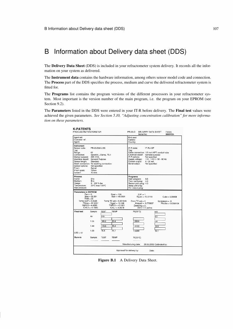
113 113
113 113
B Information about Delivery data sheet (DDS) 107
B Information about Delivery data sheet (DDS)
The Delivery Data Sheet (DDS) is included in your refractometer system delivery. It records all the infor-mation on your system as delivered.
The Instrument data contains the hardware information, among others sensor model code and connection.The Process part of the DDS specifies the process, medium and curve the delivered refractometer system isfitted for.
The Programs list contains the program versions of the different processors in your refractometer sys-tem. Most important is the version number of the main program, i.e. the program on your EPROM (seeSection 9.2).
The Parameters listed in the DDS were entered in your IT-R before delivery. The Final test values wereachieved the given parameters. See Section 5.10, “Adjusting concentration calibration” for more informa-tion on these parameters.
Figure B.1 A Delivery Data Sheet.

114 114
114 114
108 PR-03 instruction manual

115 115
115 115
C K-Patents inline refractometer calibration data report 109
C K-Patents inline refractometer calibration data report
INSTRUCTION MANUAL FOR K-PATENTS PROCESS REFRACTOMETER PR-03-D Document/Revision No. INM-3D: Rev. 1/2Effective: December 15h, 2002
71
11. K-PATENTS PROCESS REFRACTOMETER CALIBRATION DATAREPORT
CUSTOMER: _____________________________________________________________________________________
ADDRESS: _______________________________________________________________________________________
REFRACTOMETER MODEL: _______________________________________ SERIAL NO. _____________________
SAMPLE DESCRIPTION (DISSOLVED MATERIALS): ____________________________________________________
________________________________________________________________________________________________
SOLVENT: _______________________________________________________________________________________
LABORATORY METHOD: ___________________________________________________________________________
DESIRED SCALE: OUTPUT 0-100 % (4-20 MA): ________________________ UNIT: ___________________________
DATE: __________________________________________________________ SIGNATURE: ____________________
DISPLAY READINGS
SAMPLENO.
SAMPLECONC. LAB%
CONC% TEST TEMP. °C SAMPLE DATEAND TIME
SIGN
Note: See Section 5.10.6 for more information on how to fill in the calibration data report.

116 116
116 116
110 PR-03 instruction manual

117 117
117 117
D Instrument verification ISO 9000 111
D Instrument verification ISO 9000
A company that maintains a quality system according to ISO 9000 quality standard must have definedprocedures for controlling and calibrating its measuring equipment. This is required for demonstrating theconformance of the final end product to the specified requirements. The company should:
− identify the required accuracy and select an appropriate equipment for the measurements− establish calibration procedures, including check method and acceptance criteria.− calibrate the equipment at prescribed intervals against certified equipment having a known valid rela-
tionship to nationally recognized standards. When no such standard exists, the basis used for calibrationshould be documented.
This text provides a valid method for meeting the above requirements with a K-Patents inline refractometersystem. K-Patents quality system is certified against the ISO 9001 by Det Norske Veritas. K-Patents verifiesthe calibration of all delivered instruments according to a similar procedure as described in this section.
Definitions
Refractive Index (R.I.) calibration
Calibration of PR-03 with standard Refractive Index liquids:As a result of calibration procedure, a set of R.I. parameters are calculated: RIBias, RIGain, RISquare andRiCube. These parameters define the calibration polynomial, used for refractive index measurement with areference temperature of 25 ◦C.
The Refractive Index (R.I.) calibration can be traced to national standard NIST 1823, whenever certifiedstandard R.I. liquids are used in the calibration.
Accuracy of R.I. calibration
Maximum deviation accepted in R.I. calibration:The total acceptable deviation for PR-03 is R.I. 0.0006. This comes from the accuracy of PR-03(R.I. 0.0002) and from the accuracy of the standard R.I. liquids used in the calibration (R.I. 00002).
Repeatability of the R.I. calibration
Deviation from the latest R.I. calibration of PR-03:The repeatability of PR-03 is R.I. 0.0002. This can be verified as described in the following section.
Verification of Refractive Index (R.I.) calibration
The R.I. calibration can be verified with three certified standard R.I. liquids as follows:

118 118
118 118
112 PR-03 instruction manual
1. Take the sensor from the process and place it on a table.Note: Keep the PR-03-M with the flow cell and place it on a table with the flow cell (medium adaptor)up. Use the flow cell as a sample holder.
2. Allow the sensor temperature to settle close to 25 ◦C. The temperature does not have to be exactly 25 ◦C,since the differences in the calibration temperature are compensated by the software.
3. Ensure that the prism is clean without any traces of the process liquid. Use a cleaning solvent appropriatefor the process medium.
4. Use the certified standard R.I. liquids, which correspond to the values indicated in the Final test sectionof the latest Delivery Data Sheet or Standard calibration sheet of your PR-03 sensor. The three R.I.values are selected by K-Patents calibration software to represent the used R.I. range.
5. Check the R.I. calibration with the three R.I. liquids. The use of K-Patents PR-03 sample holder (seeFigure 5.15) or of the flow cell (medium adaptor) is recommended to ensure a right portion of liquid onthe prism.
6. The R.I. calibration can be checked against the standard R.I. liquid values as follows:
Display Key-in sequence Value to be checked Acceptable valuefrom Normal display
Information display D Standard RI (25◦C) Sample R.I. ± 0.0006
Corrective action if the verification fails
If the verification does not meet the acceptance criteria defined above, the following steps can be taken tocorrect the calibration of PR-03.
1. Ensure that the prism is in good condition
See Section 6 for more details of prism mounting and dismounting.
2. The following values and diagnostics should be checked from the Indicating transmitter displays withthe standard R.I. liquid on the prism.
Display Key-in sequence Value to be checked Acceptable valuefrom Normal Display
Raw sensor data C-A LED below 200Image diagnostics C-A-A-A-A Max intensity OK Yes
Endpoint below 75% YesImage below corner YesSlope OK YesLeft curve OK YesRight curve OK Yes

119 119
119 119
D Instrument verification ISO 9000 113
If the above checks 1 and 2 fail, please contact K-Patents or your local K-Patents representative for correctiveaction.
If the above check criteria are met, the instrument can be calibrated. Calibration is done with minimum five,preferably seven, standard R.I. liquids as follows:
1. Mount the sensor on the service bench.
2. Use certified standard R.I. liquids. The middle value should correspond to the middle value indicated inthe Final test section of the latest Delivery Data Sheet or Standard calibration sheet of the PR-03. Thentake 2-3 values above and below this middle value.
3. Record R.I. value and corresponding TEST and temperature values from the Normal display of PR-03.
4. Send the table of values to K-Patents or to K-Patents local representative.
5. K-Patents calculates new calibration parameters for R.I. measurement.
6. Key in the new parameters (soft keys C-B-6-1/2/3/4) and then repeat the verification check as describedabove.

120 120
120 120
114 PR-03 instruction manual

121 121
121 121
1 Index 115
Index
** CONSTANTS ERROR ** 99** DETECTOR TIMEOUT ** 98** EXTERNAL OUTPUT FAULT ** 98** NO SENSOR SIGNAL ** 99** PRISM COATED/LED FAULT ** 98** RELAY UNIT FAULT ** 98** SENSOR INTERFACE FAULT ** 99** SENSOR TRANSMISSION ERROR ** 99** TEMP MEASUREMENT FAULT ** 98** WASH STOP/EXT. STOP ** 97** WRONG CONCENTRATION PARAMETERS ** 99-WR
see Relay unit -WR3A Sanitary Standard 1
aA/D 34
bbench calibration 46BIAS
see calibration constant biasbuilt-in signal relays
see signal relays
ccalibration
benchsee bench calibration
fieldsee field calibration
temperaturesee temperature calibration
calibration constant bias 43chemically aggressive process 85chemically aggressive solutions 81Compact Optical Rigid Element
see COREcomputer
see PCconnecting
computer to IT-Rsee PC
CUBE 44current output
connection 13
ddamping 44DDS
see Delivery Data SheetDelivery Data Sheet 107DIP IN IMAGE 97dip in image 36
eENTER key 31EPROM WRITE ERROR 99
ffield calibration 45flow velocity 18
gGAIN 44
hHH 35HIGH CONC/PRISM COATED 97HIGH INTERNAL HUMIDITY 98high pressure wash 18, 25HIGH PROCESS TEMPERATURE 97HOLD 99HT 35humidity
inside sensorsee sensor humidity
iimage
opticalsee optical image
scaledsee scaled image
image detectoroutput 5

122 122
122 122
116 PR-03 instruction manual
image diagnostics 57Information display 32input switch 10input switches
configuration 36connecting 13
interconnecting cable PR-8011 18, 26inverted optical image 74
kkeyboard
layout 31
lLED 34LED value 55LOW CONCENTRATION/NO SAMPLE 97LOW LIGHT INTENSITY 97
mmounting
Compact process refractometer PR-03-D 79pipe diameter 7Probe refractometer PR-03-P 72process pressure 7Process refractometer PR-03-M 85process temperature 7Sanitary refractometer PR-03-A 65Valve body refractometer PR-03-W 89
nNORMAL OPERATION 97
ooptical image 2, 34
invertedsee inverted optical image
typical 33viewing 33
output signals 9
pparameters
see Delivery Data SheetPC
connecting with IT-R 14
power selector switch 12PR-7080
see Relay unit PR-7080see External output unit PR-7090
PR-8011see Interconnecting cable PR-8011
PRECONDITIONING 99prism coating 18, 57prism gaskets
replacing 47, 49prism wash
nozzles 20pressure 20time 20
PRISM WASH FAILURE 98process parameters
information on 32program versions 91
rR.I.
see refractive indexraw data 34RECOVERY 99refractive index 2refractometer
model 1relay
see signal relaysrelay configuration 37Relay unit -WR 18Relay unit PR-7080 18RESET key 31RETRYING WASH 97RI
see refractive indexRMN 34RMX 34
ssafety 25scaled image 35, 56Scans 34selection tree 96sensor
cooling 6
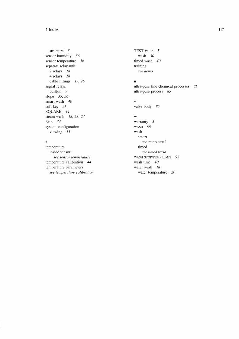
123 123
123 123
1 Index 117
structure 5sensor humidity 56sensor temperature 56separate relay unit
2 relays 184 relays 18cable fittings 17, 26
signal relaysbuilt-in 9
slope 35, 56smart wash 40soft key 31SQUARE 44steam wash 18, 23, 24Sts 34system configuration
viewing 33
ttemperature
inside sensorsee sensor temperature
temperature calibration 44temperature parameters
see temperature calibration
TEST value 5wash 30
timed wash 40training
see demo
uultra-pure fine chemical processes 81ultra-pure process 85
vvalve body 85
wwarranty 3WASH 99wash
smartsee smart wash
timedsee timed wash
WASH STOP/TEMP LIMIT 97wash time 40water wash 18
water temperature 20