Embed Size (px)
Citation preview

Toll Free : 888-774-1616 Fax : (905)-363-6998 URL: www.aero-werks.com
- 1 -
INSTRUCTION MANUAL FOR MODEL SBC
SLAT BELT CONVEYOR SYSTEM
Toll Free : 888-774-1616 Fax : (905)-363-6998 URL: www.aero-werks.com
- 2 -
TABLE OF CONTENTS
1. OPERATION 3
1.1. START UP PROCEDURE 3
1.2. SHUT DOWN PROCEDURE 3 1.3 DETERGENT 4
2. PREVENTIVE MAINTENANCE 5
2.1. DAILY 6
2.2. WEEKLY 6
2.3. MONTHLY 6
2.4. SEMI ANNUALLY 7
2.5. RETURN TRACK CORNER GUIDES 7
2.6. SPRAY ARM 8
2.7. WASH CHAMBER WATER SUPPLY 8
3. MAINTENANCE 8
3.1. REMOVAL & INSTALLATION OF SLATS 8 3.1.1. REMOVAL 8 3.1.2. INSTALLATION OF SLATS 9
3.2. BEARINGS 9
3.3. CHAIN TAKEUP 10
3.3.1. SLAT BELT CHAIN 10
3.3.2. DRIVECHAIN 11
3.4. DETERGENT FEED PUMP 11 3.4.1. REPLACING DETERGENT PUMP 12 3.4.2. DETERGENT _________________________________________________13
3.5. GEAR BOX 13
3.6. REPLACING GEAR BOX 13
4. SLAT BELT CONVEYOR PARTS 14
4.1. SBC-SLAT BELT CONVEYOR PARTS 14
4.2. SBC-SLAT BELT CONVEYOR DRIVE UNIT PARTS LIST 14
4.3. SBC-SLAT BELTCONVEYOR SINGLE TAIL UNIT PARTS LIST 15
4.4. SBC-SLAT BELT CONVEYOR PART LIST 16
4.5. ACCUMULATION SWITCH 17 5. Electrical Manual 18
DROP AREA LED LIGHTING___________________________________________31 6. Warranty_______________________________________________________________31-33
Toll Free : 888-774-1616 Fax : (905)-363-6998 URL: www.aero-werks.com
- 3 -
INSTRUCTION MANUAL FOR MODEL (SBC) SLAT BELT CONVEYOR SYSTEMS
1. OPERATION
1.1. START UP PROCEDURE
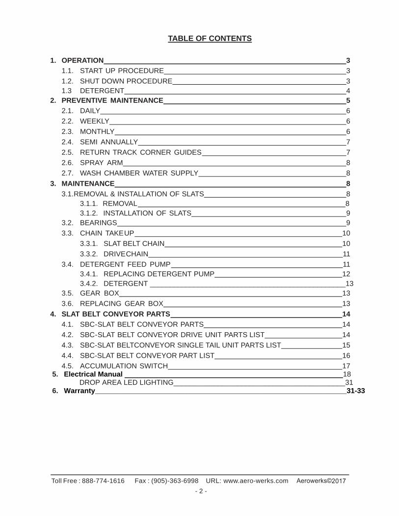
1. Make sure belt is correctly in place.
2. Turn the main disconnect switch to the ON position.
3. Run on detergent & spray for only 5-10 minutes every hour.
1.2. SHUT DOWN PROCEDURE
1. Turn the belt wash switch to spray only. Allow the system to run until the belt line is thoroughly clear of detergent suds.
2. Once the belt line has been rinsed, turn the belt wash switch to the off position, press the red stop button and turn the main disconnect off. Once the system is completely shut down, perform equipment wash down procedure.
3. Turn main disconnect off.
4. Use a heavy duty wash down hose to spray down the entire conveyor system.
5. Lift the slat belt out of the track to spray out the debris underneath, follow the arrow direction on the slat for the direction of spray.
6. Do not spray directly at the electrical control panel. Use a warm, damp cloth to wipe it down. Use detergent on cloth if heavily soiled, then wipe clean.
Toll Free : 888-774-1616 Fax : (905)-363-6998 URL: www.aero-werks.com
- 4 -
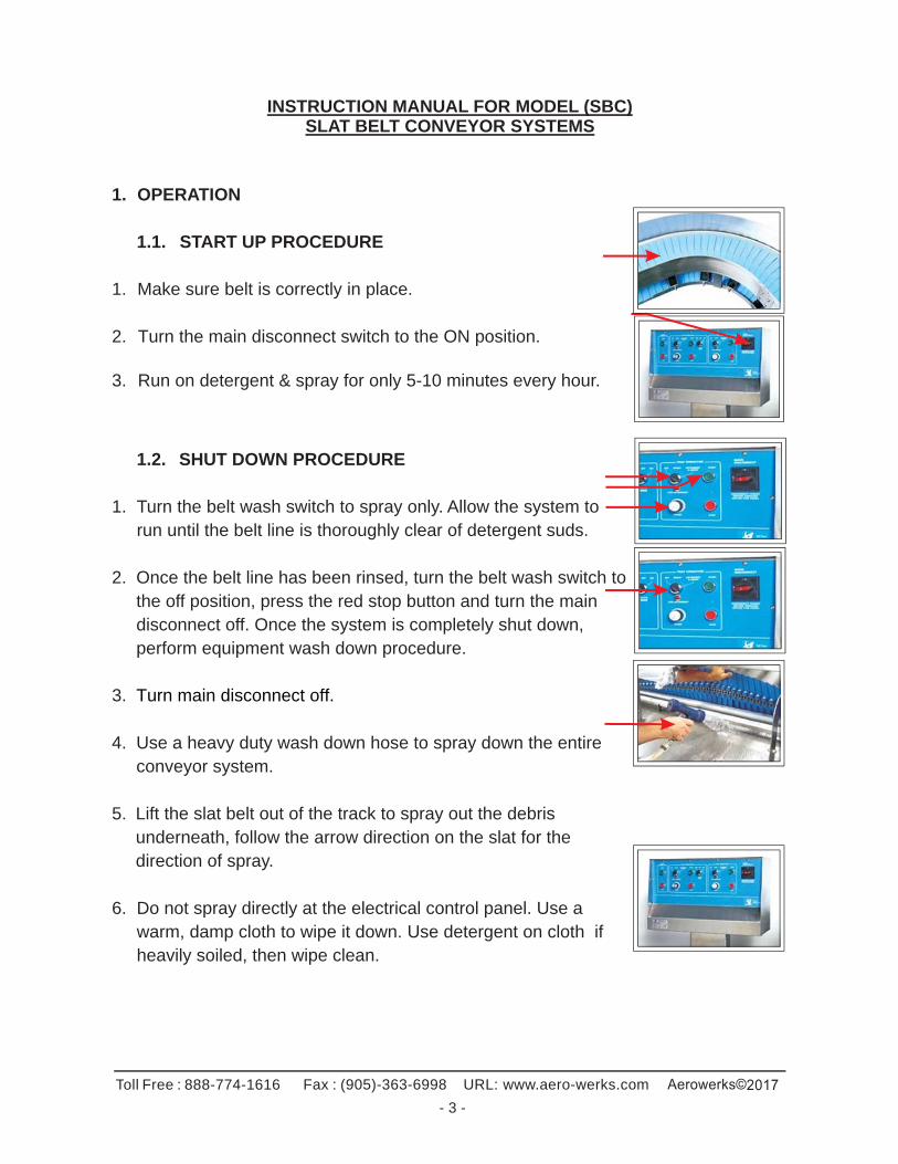
7. Make sure to lift the belt out at the corners to spray underneath.
8. Make sure it snaps completely back into place.
9. Open the drive unit wash chamber to spray the inside of the wash tank.
10. Inspect the spray arms to make sure no debris is blocking the spray holes. Make sure spray arms are correctly positioned to hit the belt.
11. Remove and clear the basket scrap pans located in the drive wash tank and the tail tank. Please note for each slat belt conveyor these two areas need to be serviced frequently.
12. Be sure to replace the strainers once they are clean and free of debris. Replace access doors and ensure belt properly in its track before restarting the conveyor.
13. Leave the belt wash switch in the OFF position. This will allow the belt to self- clean by draining out the water that has accumulated in the channels on top and bottom. This is the only time belt should be operated without the spray on.
14. Shut down entire system by turning the main disconnect
switch to the off position.
15. Once the conveyor system is completely shut down remove the belt from its upper track and place on the side to further aid in the drying process overnight or between shifts.
1.3 DETERGENT
To prevent mold growth on the slat belt, use ECOLAB (or equivalent) Sani Glide detergent. It must be diluted to 1 part detergent to 5 parts water. Water temperature must be at least 105° F.
Toll Free : 888-774-1616 Fax : (905)-363-6998 URL: www.aero-werks.com
- 5 -
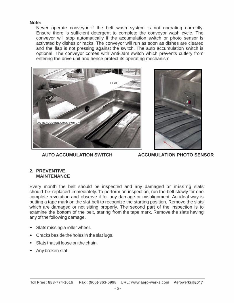
Note: Never operate conveyor if the belt wash system is not operating correctly. Ensure there is sufficient detergent to complete the conveyor wash cycle. The conveyor will stop automatically if the accumulation switch or photo sensor is activated by dishes or racks. The conveyor will run as soon as dishes are cleared and the flap is not pressing against the switch. The auto accumulation switch is optional. The conveyor comes with Anti-Jam switch which prevents cutlery from entering the drive unit and hence protect its operating mechanism.
FLAP AUTO ACCUMULATION SWITCH
AUTO ACCUMULATION SWITCH ACCUMULATION PHOTO SENSOR
2. PREVENTIVE MAINTENANCE
Every month the belt should be inspected and any damaged or missing slats should be replaced immediately. To perform an inspection, run the belt slowly for one complete revolution and observe it for any damage or misalignment. An ideal way is putting a tape mark on the slat belt to recognize the starting position. Remove the slats which are damaged or not sitting properly. The second part of the inspection is to examine the bottom of the belt, staring from the tape mark. Remove the slats having any of the following damage. • Slats missing a roller wheel.
• Cracks beside the holes in the slat lugs.
• Slats that sit loose on the chain.
• Any broken slat.
Toll Free : 888-774-1616 Fax : (905)-363-6998 URL: www.aero-werks.com
- 6 -
2.1. DAILY
1. Remove the basket strainers from the drive and tail units, clean and replace them. 2. If your unit is equipped with a 'hose wash down station', use this hose to wash the
scrapping table and slat belt conveyor to remove all debris. When hosing down the system, make sure that no water gets into the sensor. (Optional equipment).
3. Check the top and bottom of the entire belt line and remove if there are any foreign
objects (knives, forks, plastic, etc.).These objects will hinder the performance of the conveyor unit and may cause jams.
4. If your unit is equipped with accumulation switches make sure that they are free from
obstructions. System will not start unless the obstructions are cleared.
Clean out any foreign matter from the conveyor belt, underneath the belt and in the return track where exposed.
2.2. WEEKLY
Replace any missing slats. See section 3.1 for more information. 1. Clean the areas, which are not accessible to the hose, using a wet soapy cloth.
Use hard water cleaners to clean areas where hard water build-up may occur. 2. Check the detergent pump to make sure it is operating effectively. 3. Clean out any foreign body from the conveyor belt, underneath the belt and in the
return track.
2.3. MONTHLY
1. Ensure that there is sufficient detergent available in stock. It is recommended to have an inventory of detergent, which typically lasts for up to a month.
2. Inspect entire belt line and replace any slats that are missing. The slats with broken
edges, cracks and missing rollers should also be replaced. See section 3.1 for more information.
3. Check sag of slat belt in drive unit. If belt is sagging too much & close to bottom
spray arm, remove a chain link. See section 3.3. 4. Make sure that all the switches are functioning correctly. 5. Remove and flush out spray arms located in the drive unit.
A qualified mechanic should perform this work.
Toll Free : 888-774-1616 Fax : (905)-363-6998 URL: www.aero-werks.com
- 7 -
2.4. SEMI-ANNUALLY
Inspect the slat belt chain for excessive slack caused by stretching. The excessive slack can be removed by adjusting the length of the chain. Please refer the section 3.3 of this manual for details.
1. Inspect plastic wear strips. Worn or damaged strips should be replaced immediately. 2. Apply food-grade grease to flange bearings and drive chain located in the drive unit.
Contact Aerowerks for grease available in solid and Aerosol form. Use only food -grade lithium grease.
3. Ensure the slat belt is at the center of the openings on both drive and tail ends.
If the belt has shifted from off-center adjust the position of the corresponding sprockets.
4. Check the oil quality and level in the gearbox. For the gearbox oil change,
please refer the section 3.5 for more Information.
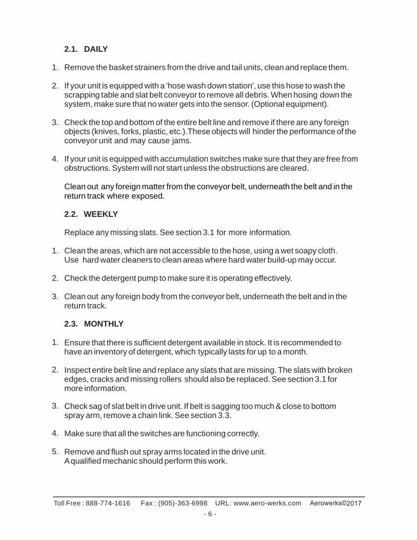
2.5. RETURN TRACK CORNER GUIDES
The Aerowerks conveyor belt is unique in its use of small guide wheels on the bottom to reduce the cornering friction. As the belt is upside down on the return track, special cornering guides are employed to engage these wheels and guide the belt around corners. The proper operation of the system is dependent upon these guides being correctly set up.
When properly set up the belt should go around the corners without the tips of the slats touching either the inside or outside edges of the return track. The system is designed to allow a 1/8” gap between the tips of the slats and the edges of the return track. Also adjust the guide rails to have 1/8” vertical gap between the bottom surface of the slat and the guide rail. (Please refer to figure above). Once adjusted, the guide rail should be locked in place by tightening the nuts. Apply sealant such as Loctite 262 to the nuts to prevent them from loosening due to vibration during operation. The most common indication of return track misalignment is wearing of the slats on one side.
Toll Free : 888-774-1616 Fax : (905)-363-6998 URL: www.aero-werks.com
- 8 -
2.6. SPRAY ARM
The belt is washed within the drive unit by two fixed stainless steel spray arms. The spray arms can be taken out by removing the large plastic union nut located on the rear side of tank. Inspect the spray arms for any damage or clogged spray holes. Once spray arms are replaced, make sure that they are properly oriented to have the water jet holes pointing directly towards the belt. Start the unit and adjust the water pressure. Inspect the spray arm for any leaks at the connection points.
2.7. WASH CHAMBER WATER SUPPLY
The incoming water for the slat belt wash should be set at 105 degree Fahrenheit (40 degree Celsius) with 60psi water pressure. This is required to ensure effective cleaning of the slat belt. All plumbing connections must be done by a qualified plumber in accordance with local codes.
3. MAINTENANCE
Before performing any maintenance operation on equipment, shut down the conveyor and disconnect the power at your main circuit breaker.
3.1. REMOVAL & INSTALLATION OF SLATS
The Aerowerks slat is specially designed for easy installation and removal from the stainless steel side-bow chain. Once the slats are assembled, the extended pins of the chain must be completely engaged in the holes provided in the slat. This is usually ensured by a “clicking” sound heard during the assembly. The slat should lay flat and straight when properly installed as shown below.
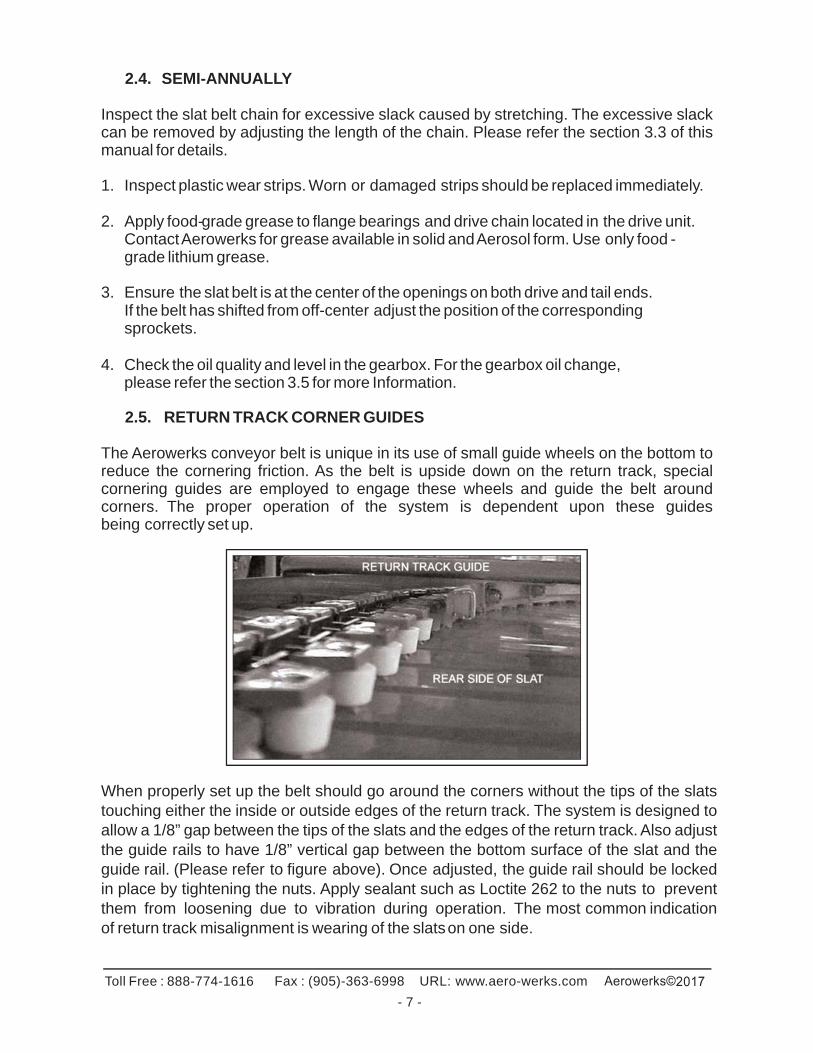
3.1.1. REMOVAL
Engage one end of the slat in slat tool and arch the slat by grasping the other end. Pull away the slat once the pins on the chain disengage the holes in the slat lugs.
Note: The slat tool aides in removal & installation of slat and is available for purchase from Aerowerks.
Toll Free : 888-774-1616 Fax : (905)-363-6998 URL: www.aero-werks.com
- 9 -
Slat tool part number:
For 10” Slat: 0214003
For 12” Slat: 0218301
Under no circumstances should slats shall be hammered to mount on the chain. This will cause the extended pin to damage the nesting holes causing the slat to be out of level with the rest of the belt. Do not run the system when more than three adjacent slats are missing.
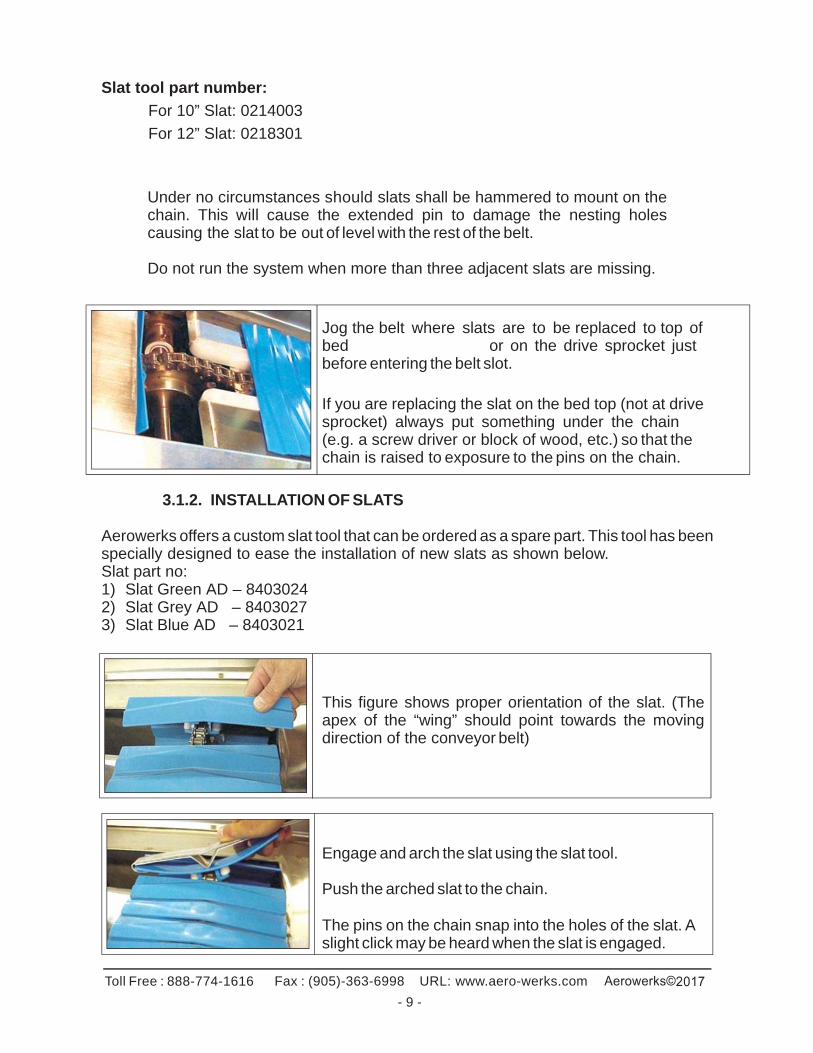
Jog the belt where slats are to be replaced to top of bed or on the drive sprocket just before entering the belt slot.
If you are replacing the slat on the bed top (not at drive sprocket) always put something under the chain (e.g. a screw driver or block of wood, etc.) so that the chain is raised to exposure to the pins on the chain.
3.1.2. INSTALLATION OF SLATS Aerowerks offers a custom slat tool that can be ordered as a spare part. This tool has been specially designed to ease the installation of new slats as shown below. Slat part no: 1) Slat Green AD – 8403024 2) Slat Grey AD – 8403027 3) Slat Blue AD – 8403021
This figure shows proper orientation of the slat. (The apex of the “wing” should point towards the moving direction of the conveyor belt)
Engage and arch the slat using the slat tool.
Push the arched slat to the chain.
The pins on the chain snap into the holes of the slat. A slight click may be heard when the slat is engaged.
Toll Free : 888-774-1616 Fax : (905)-363-6998 URL: www.aero-werks.com
- 10 -
3.2. BEARINGS
Two bearings, 1” dia. are located in the drive unit. These bearings shall be lubricated once a year from the date of start up with food-grade grease only. Contact Aerowerks to purchase proper grease.
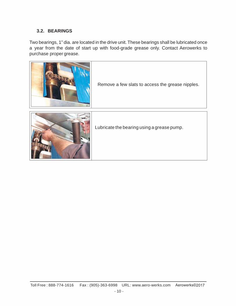
Remove a few slats to access the grease nipples.
Lubricate the bearing using a grease pump.
Toll Free : 888-774-1616 Fax : (905)-363-6998 URL: www.aero-werks.com
- 10 -
3.3. CHAIN TAKE UP
3.3.1. SLAT BELT CHAIN
The slats are attached t o a stainless steel slat belt chain. Under normal operating conditions this chain should not require any replacement. However over a period of time, the chain stretches; this is normal. Regular adjustment to reduce the length is required. Follow these steps to reduce the length of the slat belt chain.
Note: There is no master link, chain can be separated at any point.
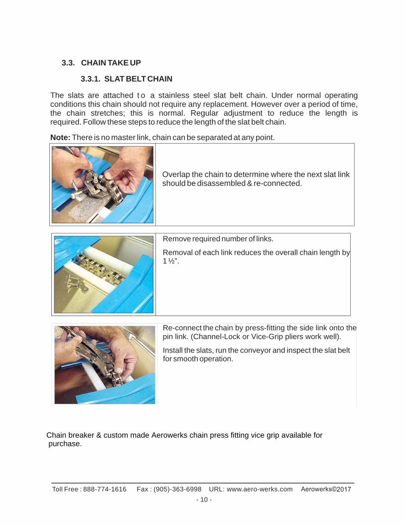
Overlap the chain to determine where the next slat link should be disassembled & re-connected.
Remove required number of links.
Removal of each link reduces the overall chain length by 1 ½”.
Re-connect the chain by press-fitting the side link onto the pin link. (Channel-Lock or Vice-Grip pliers work well).
Install the slats, run the conveyor and inspect the slat belt for smooth operation.
Chain breaker & custom made Aerowerks chain press fitting vice grip available for purchase.
Toll Free : 888-774-1616 Fax : (905)-363-6998 URL: www.aero-werks.com
- 11 -
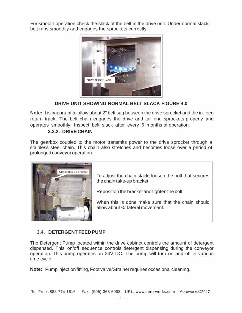
For smooth operation check the slack of the belt in the drive unit. Under normal slack, belt runs smoothly and engages the sprockets correctly.
Normal Belt Slack
DRIVE UNIT SHOWING NORMAL BELT SLACK FIGURE 4.0
Note: It is important to allow about 2” belt sag between the drive sprocket and the in-feed return track. T he belt chain engages the drive and tail end sprockets properly and operates smoothly. Inspect belt slack after every 6 months of operation.
3.3.2. DRIVE CHAIN The gearbox coupled to the motor transmits power to the drive sprocket through a stainless steel chain. This chain also stretches and becomes loose over a period of prolonged conveyor operation.
To adjust the chain slack, loosen the bolt that secures the chain take-up bracket.
Reposition the bracket and tighten the bolt.
When this is done make sure that the chain should allow about ¾” lateral movement.
3.4. DETERGENT FEED PUMP
The Detergent Pump located within the drive cabinet controls the amount of detergent dispensed. This on/off sequence controls detergent dispensing during the conveyor operation. This pump operates on 24V DC. The pump will turn on and off in various time cycle.
Note: Pump injection fitting, Foot valve/Strainer requires occasional cleaning.
Toll Free : 888-774-1616 Fax : (905)-363-6998 URL: www.aero-werks.com
- 12 -
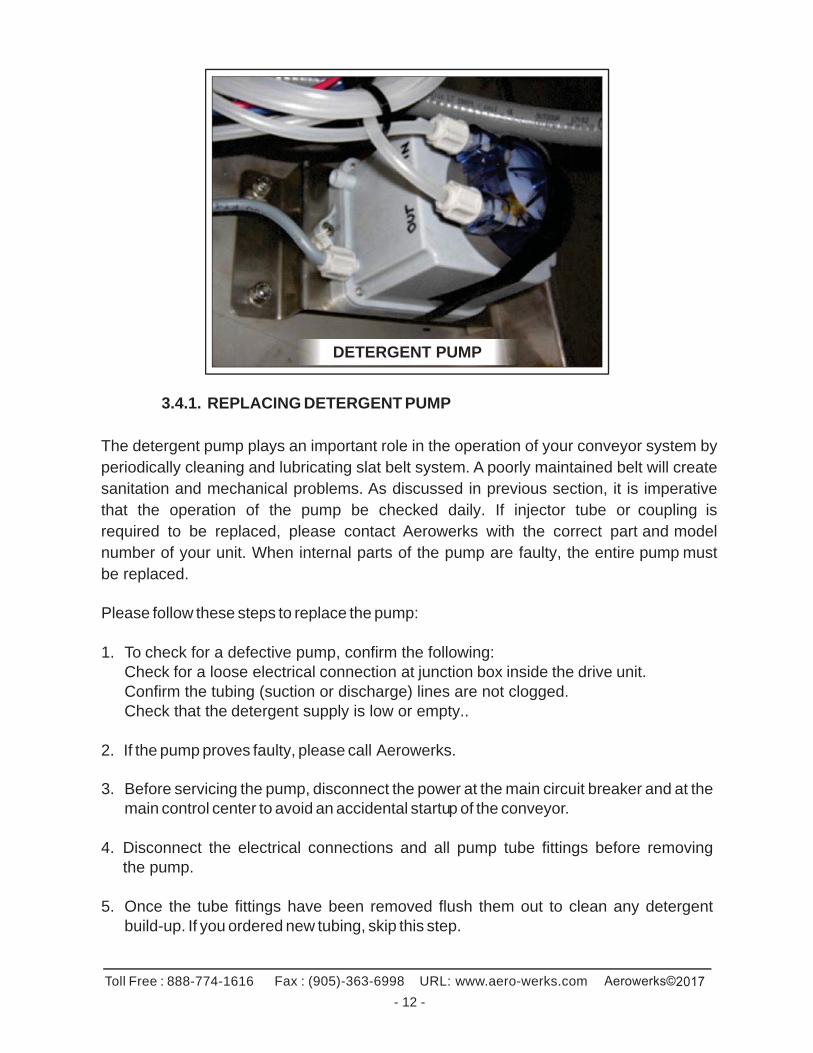
DETERGENT PUMP
3.4.1. REPLACING DETERGENT PUMP
The detergent pump plays an important role in the operation of your conveyor system by periodically cleaning and lubricating slat belt system. A poorly maintained belt will create sanitation and mechanical problems. As discussed in previous section, it is imperative that the operation of the pump be checked daily. If injector tube or coupling is required to be replaced, please contact Aerowerks with the correct part and model number of your unit. When internal parts of the pump are faulty, the entire pump must be replaced.
Please follow these steps to replace the pump:
1. To check for a defective pump, confirm the following: Check for a loose electrical connection at junction box inside the drive unit. Confirm the tubing (suction or discharge) lines are not clogged. Check that the detergent supply is low or empty..
2. If the pump proves faulty, please call Aerowerks.
3. Before servicing the pump, disconnect the power at the main circuit breaker and at the main control center to avoid an accidental startup of the conveyor.
4. Disconnect the electrical connections and all pump tube fittings before removing
the pump. 5. Once the tube fittings have been removed flush them out to clean any detergent
build-up. If you ordered new tubing, skip this step.
Toll Free : 888-774-1616 Fax : (905)-363-6998 URL: www.aero-werks.com
- 13 -
6. Install new pump using existing support studs and nuts. If the support studs are damaged or have broken off, replace them before installing the new unit.
7. Once pump is in place reconnect all electrical terminals and tube fittings. 8. Before starting the unit, make sure that the detergent tank is full and the float in the
detergent tank is sitting at the bottom. 9. When a new pump installed, the suction line will be dry and requires some time
for priming.
If the pump is required to be replaced within the warranty period, please contact Aerowerks to obtain the Return Goods Authorization (R.G.A) number before ordering. The old pump must be returned to Aerowerks as soon as possible to validate the warranty claim.
3.4.2 DETERGENT
Contact your dish machine detergent supplier. Recommended detergent Ecolab Klenz-Glide. For compatibility with the Aerowerks plastic slats, the detergent must meet the following criteria:
Non-abrasive Non-caustic Biodegradable Low-sudsing Non-quaternary Good lubrication qualities
Add one gallon of detergent to an empty 5-gallon pail. Add 4 gallons of water. Aerowerks detergent pump has been pre-set to deliver detergent/water mixture to effectively clean/lubricate the belt. Further adjustment may be required to suit individual systems.
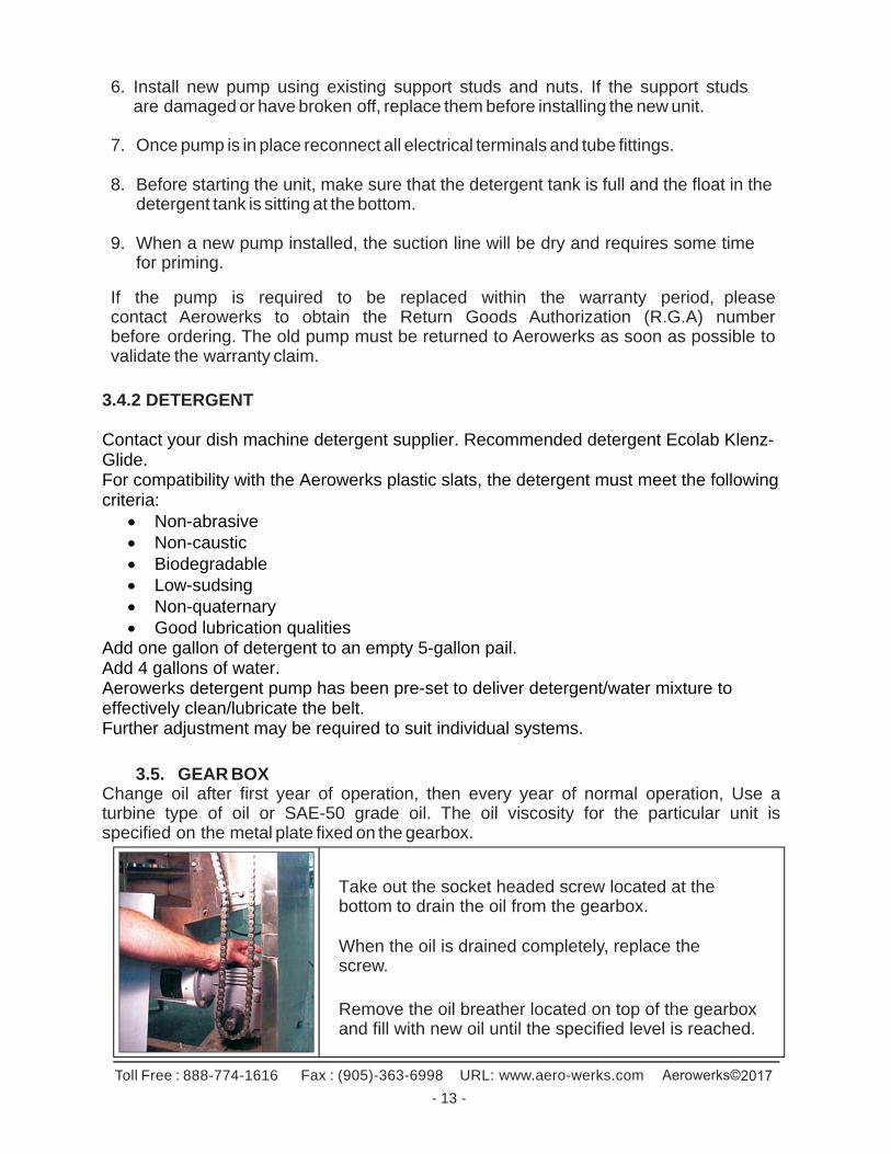
3.5. GEAR BOX Change oil after first year of operation, then every year of normal operation, Use a turbine type of oil or SAE-50 grade oil. The oil viscosity for the particular unit is specified on the metal plate fixed on the gearbox.
Take out the socket headed screw located at the bottom to drain the oil from the gearbox.
When the oil is drained completely, replace the screw.
Remove the oil breather located on top of the gearbox and fill with new oil until the specified level is reached.
Toll Free : 888-774-1616 Fax : (905)-363-6998 URL: www.aero-werks.com
- 14 -
3.6. REPLACING GEARBOX
• Shut off and lock out the main disconnect before beginning. • Loosen the bolt that secures the chain take up bracket, to release the tension
on the drive chain. Remove master link and remove chain. • Remove all the bolts connecting the gearbox to the motor and remove motor. • Finally remove the bolts which secure the gearbox to the drive unit frame. • When re-mounting the gear box, reverse the same steps. Also see section
3.3.2 on adjusting drive chain tension.
Toll Free : 888-774-1616 Fax : (905)-363-6998 URL: www.aero-werks.com
- 15 -
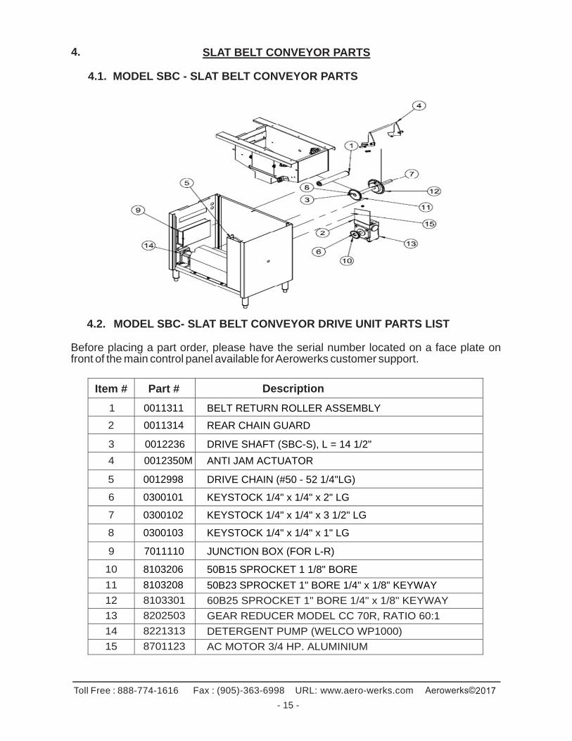
4. SLAT BELT CONVEYOR PARTS
4.1. MODEL SBC - SLAT BELT CONVEYOR PARTS
4.2. MODEL SBC- SLAT BELT CONVEYOR DRIVE UNIT PARTS LIST
Before placing a part order, please have the serial number located on a face plate on front of the main control panel available for Aerowerks customer support.
Item # Part # Description
1 0011311 BELT RETURN ROLLER ASSEMBLY
2 0011314 REAR CHAIN GUARD
3 0012236 DRIVE SHAFT (SBC-S), L = 14 1/2"
4 0012350M ANTI JAM ACTUATOR
5 0012998 DRIVE CHAIN (#50 - 52 1/4"LG)
6 0300101 KEYSTOCK 1/4" x 1/4" x 2" LG
7 0300102 KEYSTOCK 1/4" x 1/4" x 3 1/2" LG
8 0300103 KEYSTOCK 1/4" x 1/4" x 1" LG
9 7011110 JUNCTION BOX (FOR L-R)
10 8103206 50B15 SPROCKET 1 1/8" BORE
11 8103208 50B23 SPROCKET 1" BORE 1/4" x 1/8" KEYWAY
12 8103301 60B25 SPROCKET 1" BORE 1/4" x 1/8" KEYWAY
13 8202503 GEAR REDUCER MODEL CC 70R, RATIO 60:1
14 8221313 DETERGENT PUMP (WELCO WP1000)
15 8701123 AC MOTOR 3/4 HP. ALUMINIUM
Toll Free : 888-774-1616 Fax : (905)-363-6998 URL: www.aero-werks.com
- 16 -
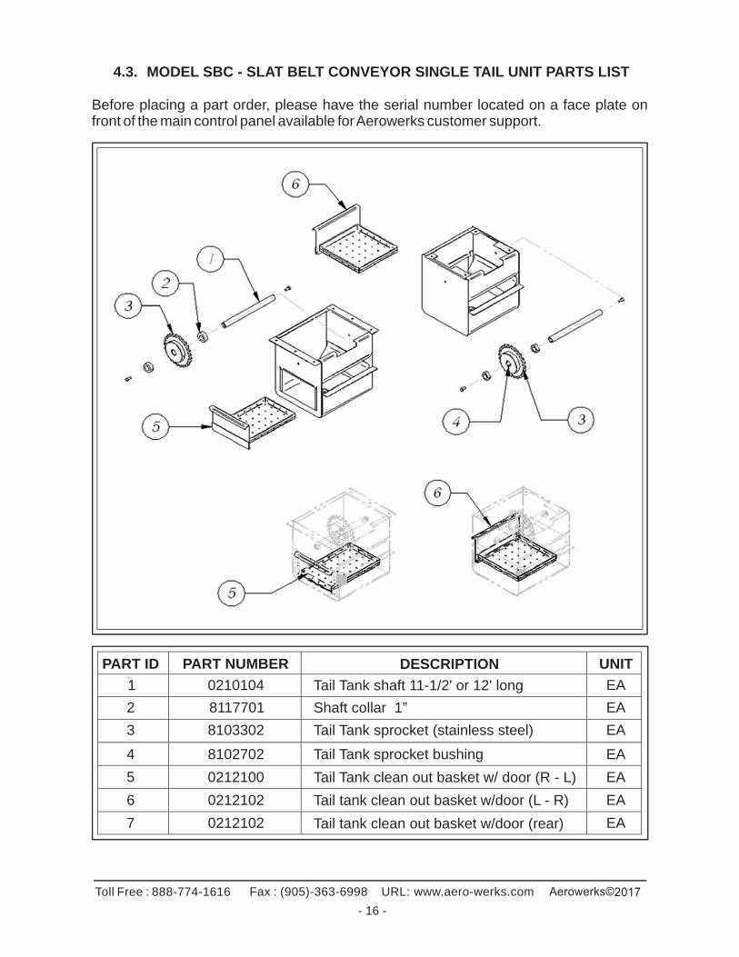
4.3. MODEL SBC - SLAT BELT CONVEYOR SINGLE TAIL UNIT PARTS LIST
Before placing a part order, please have the serial number located on a face plate on front of the main control panel available for Aerowerks customer support.
PART ID PART NUMBER DESCRIPTION UNIT
1 0210104 Tail Tank shaft 11-1/2' or 12' long EA
2 8117701 Shaft collar 1” EA
3 8103302 Tail Tank sprocket (stainless steel) EA
4 8102702 Tail Tank sprocket bushing EA
5 0212100 Tail Tank clean out basket w/ door (R - L) EA
6 0212102 Tail tank clean out basket w/door (L - R) EA
7 0212102 Tail tank clean out basket w/door (rear) EA
Toll Free : 888-774-1616 Fax : (905)-363-6998 URL: www.aero-werks.com
- 17 -
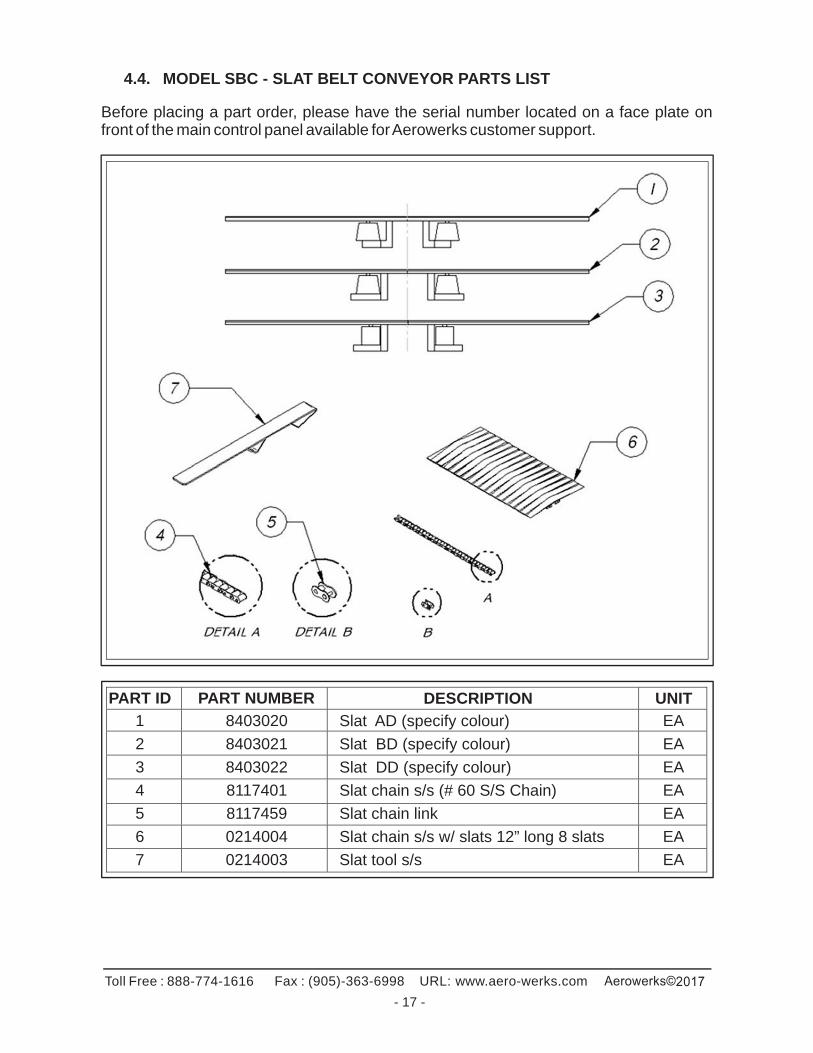
4.4. MODEL SBC - SLAT BELT CONVEYOR PARTS LIST
Before placing a part order, please have the serial number located on a face plate on front of the main control panel available for Aerowerks customer support.
PART ID PART NUMBER DESCRIPTION UNIT
1 8403020 Slat AD (specify colour) EA
2 8403021 Slat BD (specify colour) EA
3 8403022 Slat DD (specify colour) EA
4 8117401 Slat chain s/s (# 60 S/S Chain) EA
5 8117459 Slat chain link EA
6 0214004 Slat chain s/s w/ slats 12” long 8 slats EA
7 0214003 Slat tool s/s EA
Toll Free : 888-774-1616 Fax : (905)-363-6998 URL: www.aero-werks.com
- 18 -
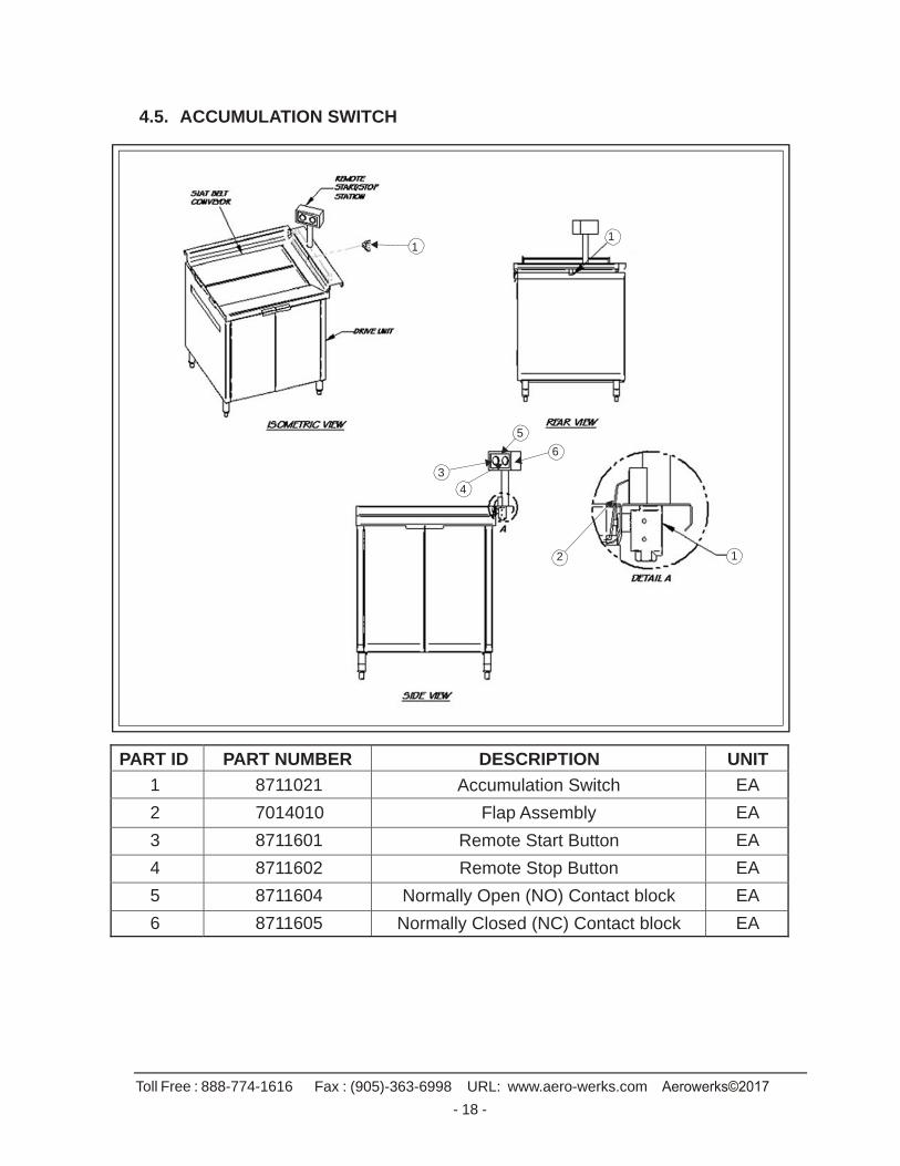
4.5. ACCUMULATION SWITCH
1 1
5
6
3
4
2 1
PART ID PART NUMBER DESCRIPTION UNIT
1 8711021 Accumulation Switch EA
2 7014010 Flap Assembly EA
3 8711601 Remote Start Button EA
4 8711602 Remote Stop Button EA
5 8711604 Normally Open (NO) Contact block EA
6 8711605 Normally Closed (NC) Contact block EA
Toll Free : 888-774-1616 Fax : (905)-363-6998 URL: www.aero-werks.com
- 19 -
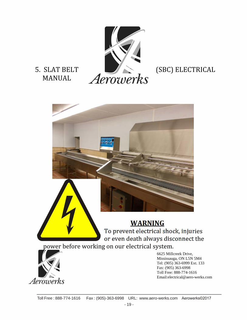
5.SLATBELT (SBC)ELECTRICALMANUAL
WARNINGTopreventelectricalshock,injuriesorevendeathalwaysdisconnectthe
powerbeforeworkingonourelectricalsystem.
6625 Millcreek Drive, Mississauga, ON L5N 5M4 Tel: (905) 363-6999 Ext. 133 Fax: (905) 363-6998 Toll Free: 888-774-1616 Email:[email protected]
Toll Free : 888-774-1616 Fax : (905)-363-6998 URL: www.aero-werks.com
- 20 -
Slat Belt Electrical Manual
TableofContentsAbout ........................................................................................................................................................... 19
Panel Components ................................................................................................................................. 20‐21
DC Power Supply ..................................................................................................................................... 20
Disconnect ............................................................................................................................................... 20
Fuse Blocks .............................................................................................................................................. 20
Mini Breaker ............................................................................................................................................ 20
Programmable Logic Controller (PLC) ..................................................................................................... 21
Variable Frequency Drive (VFD) .............................................................................................................. 21
Relay ........................................................................................................................................................ 21
Machine Components (optional) .......................................................................................................... 22‐26
Detergent Pump ...................................................................................................................................... 22
Detergent Pump Prime button ................................................................................................................ 22
Solenoid ................................................................................................................................................... 22
Motor ....................................................................................................................................................... 23
Anti‐Jam Switch ....................................................................................................................................... 23
Auto‐Rinse Station ................................................................................................................................... 24
Accumulation Limit Switch ...................................................................................................................... 25
Accumulation Proximity Sensor .............................................................................................................. 25
Hip Switch ................................................................................................................................................ 26
Troubleshooting ..................................................................................................................................... 27‐30
Not Running ........................................................................................................................................ 27‐28
Belt Spray ................................................................................................................................................. 28
Pump ....................................................................................................................................................... 28
Accumulation ........................................................................................................................................... 28
Anti‐Jam ................................................................................................................................................... 29
Auto‐rinse ........................................................................................................................................... 29‐30
Speed Control .......................................................................................................................................... 30
Replacing the potentiometer ................................................................................................................ 30‐31
Toll Free : 888-774-1616 Fax : (905)-363-6998 URL: www.aero-werks.com
- 21 -
About
This manual covers the Aerowerks slat belt conveyors electrical systems and assist the user to troubleshoot and optimize its performance. The main control panel is not waterproof and under no circumstances shall the control panel be hosed down with water.
Panel Components The electrical control panel contains many different electrical
components that are used on a case by case basis. These components are DC power supplies, disconnects, fuse blocks, programmable logic controllers (PLC),
Variable Frequency Drives (VFD), and relays.
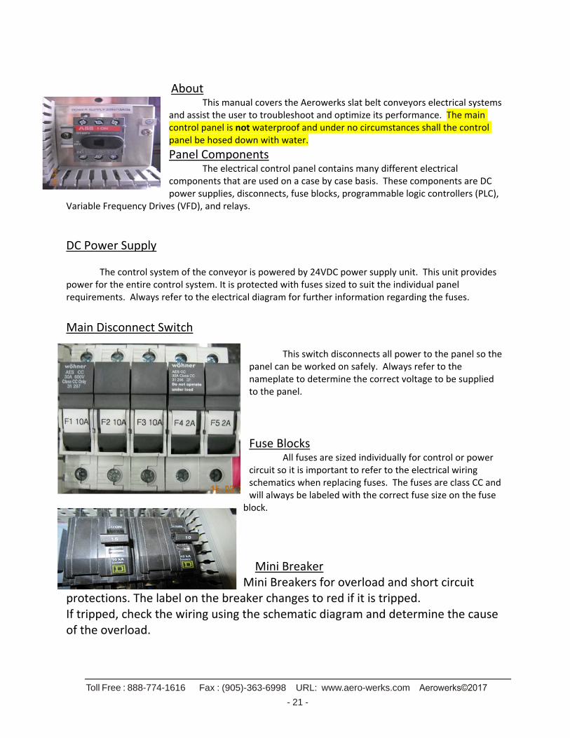
DC Power Supply The control system of the conveyor is powered by 24VDC power supply unit. This unit provides power for the entire control system. It is protected with fuses sized to suit the individual panel requirements. Always refer to the electrical diagram for further information regarding the fuses.
Main Disconnect Switch
This switch disconnects all power to the panel so the panel can be worked on safely. Always refer to the nameplate to determine the correct voltage to be supplied to the panel.
Fuse Blocks All fuses are sized individually for control or power
circuit so it is important to refer to the electrical wiring schematics when replacing fuses. The fuses are class CC and will always be labeled with the correct fuse size on the fuse
block.
Mini Breaker
Mini Breakers for overload and short circuit protections. The label on the breaker changes to red if it is tripped. If tripped, check the wiring using the schematic diagram and determine the cause of the overload.
Toll Free : 888-774-1616 Fax : (905)-363-6998 URL: www.aero-werks.com
- 22 -
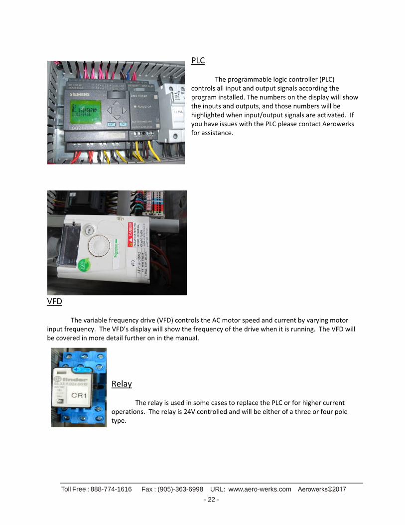
PLC The programmable logic controller (PLC) controls all input and output signals according the program installed. The numbers on the display will show the inputs and outputs, and those numbers will be highlighted when input/output signals are activated. If you have issues with the PLC please contact Aerowerks for assistance.
VFD
The variable frequency drive (VFD) controls the AC motor speed and current by varying motor input frequency. The VFD’s display will show the frequency of the drive when it is running. The VFD will be covered in more detail further on in the manual.
Relay The relay is used in some cases to replace the PLC or for higher current operations. The relay is 24V controlled and will be either of a three or four pole type.
Toll Free : 888-774-1616 Fax : (905)-363-6998 URL: www.aero-werks.com
- 23 -
Machine Components (optional) Please note that these components will vary depending on the conveyor.
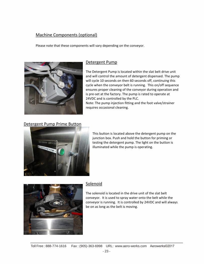
Detergent Pump The Detergent Pump is located within the slat belt drive unit and will control the amount of detergent dispensed. The pump will cycle 10 seconds on then 60 seconds off, continuing this cycle when the conveyor belt is running. This on/off sequence ensures proper cleaning of the conveyor during operation and is pre‐set at the factory. The pump is rated to operate at 24VDC and is controlled by the PLC. Note: The pump injection fitting and the foot valve/strainer requires occasional cleaning.
Detergent Pump Prime Button
This button is located above the detergent pump on the junction box. Push and hold the button for priming or testing the detergent pump. The light on the button is illuminated while the pump is operating.
Solenoid
The solenoid is located in the drive unit of the slat belt conveyor. It is used to spray water onto the belt while the conveyor is running. It is controlled by 24VDC and will always be on as long as the belt is moving.

Toll Free : 888-774-1616 Fax : (905)-363-6998 URL: www.aero-werks.com
- 24 -
Motor The motor for the slat belt is located in the drive unit. The motor
is a Keltech 0.75 HP AC motor by convention but always check
your electrical drawing to confirm. The VFD operates this motor
when the conveyor is running.
Anti‐Jam Switch
The anti‐jam switch is located in the drive unit and can be seen from the outside from the top. It protects objects such as clothing or fingers from becoming wedged in the belt opening, causing possible personal injury or damage to the conveyor. The unit is mounted on a pivot such that the bar (see photo) moves forward if an object enters the belt
opening area. A magnetic switch attached to it will disengage, causing the conveyor to stop immediately. The cause of the jam should be checked and cleared. The conveyor must be re‐started at a control station or the main panel. The panel has an anti‐jam light that will illuminate when the pivot bar is displaced and the switch is disengaged indicating a jam. When the pivot bar is returned to its rest position, the light will turn off and the conveyor can be re‐started by the start button Occasionally, the switch may remain in the forward position with the light on and the conveyor off, even after the cause of the jam is removed. The pivot bar may have become misaligned. Manually move the bar back and forth until it pivots freely and returns to it rest position. The light shuts off.

Toll Free : 888-774-1616 Fax : (905)-363-6998 URL: www.aero-werks.com
- 25 -
Auto‐Rinse Station (This is an optional item used on the scrapping table to automatically rinse soiled dishware). The auto‐rinse station sprays a stream of water as long as the sensor beam is interrupted by an item (dishware). When the item is removed clear of the beam it will continue to spray for three seconds, then stop until the sensor beam is again interrupted. The auto rinse unit involves two areas. The first being the plumbing box (located under the scrapping table) containing the solenoids that open and close the water supply valves. The solenoids are numbered from left to right and from top to bottom as one to three. They are wired one as a gray wire, two as a
black wire and three as a white wire. All wires are tagged with wire numbers for convenience. The second part is the actual auto‐rinse station that includes the sensor and the water supply pipe. The sensor is a proximity type with a range of approximately three inches. Note that it is important to keep the sensor eye clean on a regular basis as excessive dirt or debris will cause the sensor to trigger falsely.
Accumulation Limit Switch The accumulation switch is used to stop the conveyor when a tray has traveled to the end of the belt. This type of accumulation switch is a mechanically‐actuated switch that tells the PLC or Relay to shut off the motor temporarily until it is released. The switch is activated when an object (tray) depresses a stainless steel pivoting flap as shown in the second picture. When the accumulation switch is activated a light on the panel illuminates. As soon as the switch is released
the light will turn off and the conveyor will automatically re‐start. Note: When washing the conveyor never direct the hose spray towards the accumulation switch. If water gets into the switch it will malfunction. The accumulation switch prevents jamming of trays and if it malfunctions it must be replaced immediate.
Toll Free : 888-774-1616 Fax : (905)-363-6998 URL: www.aero-werks.com
- 26 -
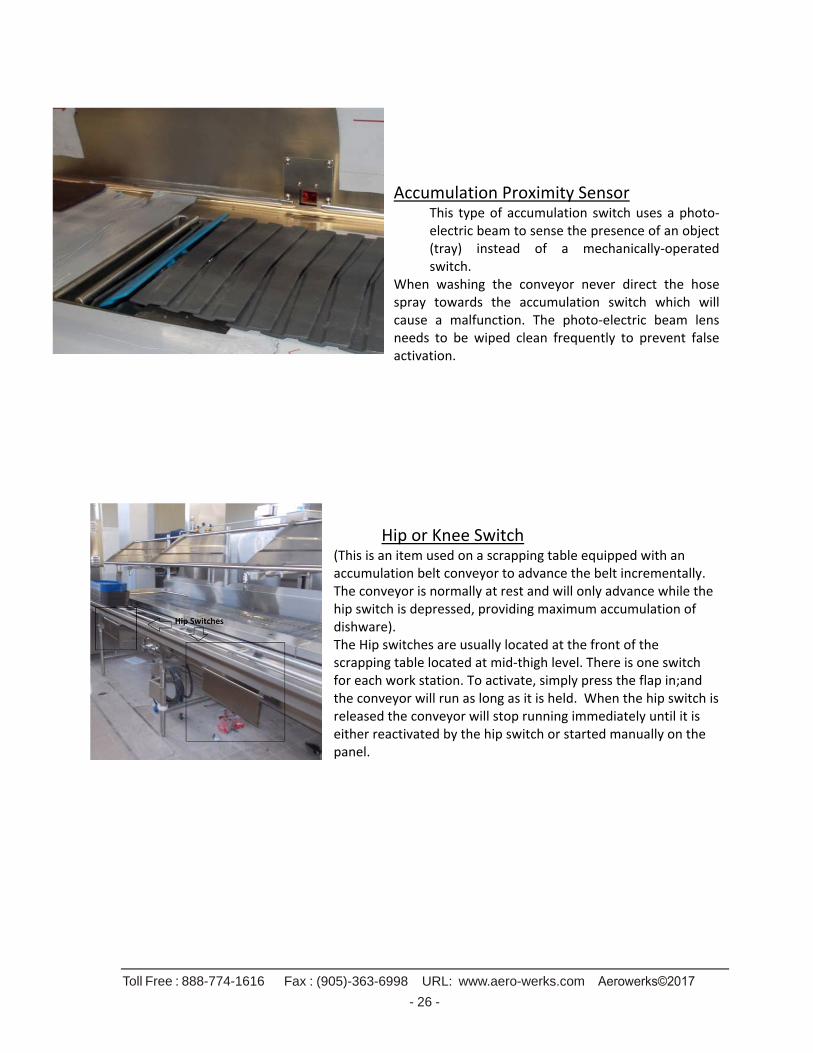
Accumulation Proximity Sensor This type of accumulation switch uses a photo‐electric beam to sense the presence of an object (tray) instead of a mechanically‐operated switch.
When washing the conveyor never direct the hose spray towards the accumulation switch which will cause a malfunction. The photo‐electric beam lens needs to be wiped clean frequently to prevent false activation.
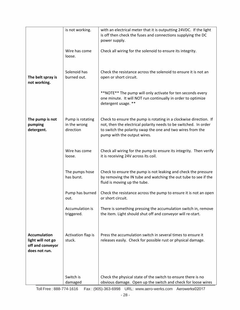
Hip or Knee Switch (This is an item used on a scrapping table equipped with an accumulation belt conveyor to advance the belt incrementally. The conveyor is normally at rest and will only advance while the hip switch is depressed, providing maximum accumulation of dishware). The Hip switches are usually located at the front of the scrapping table located at mid‐thigh level. There is one switch for each work station. To activate, simply press the flap in;and the conveyor will run as long as it is held. When the hip switch is released the conveyor will stop running immediately until it is either reactivated by the hip switch or started manually on the panel.

Toll Free : 888-774-1616 Fax : (905)-363-6998 URL: www.aero-werks.com
- 27 -
Troubleshooting
PROBLEM
POSSIBLE CAUSE
SOLUTION
Start Button is pushed but conveyor does not start.
System is not getting power Conveyor speed is set to 0% The anti‐jam light is on. The accumulation light is on. Excessive mechanical load. VFD Fault Motor is damaged or not receiving power. DC power supply
Verify that the main power breaker is on and the system is getting power. Increase the conveyor speed. Check the anti‐jam switch at the drive end of the belt to insure there are no obstructions and reset it to its home position. Check the accumulation switch and insure the switch is not pressed in. If not, the switch may be damaged. Shut off power then open the accumulation switch and inspect for damage or water internally. To verify if there is an excessive mechanical load, do the following: open the panel, turn the power on, look for the VFD. It is labelled “VFD” on the lower right side, Press the start button, check the VFD and if the display shows “OCF” or display is blinking then the load is excessive. The entire belt and return track must be checked for any snags or obvious damage. Check for possible utensils or tools wedged in the belt. To verify if there is VFD fault, do the following: open the panel, turn the power on, locate the VFD as noted above, press the start button and observe the display. If there is an error code other than AC.Lt or lt.AC, contact Aerowerks for further assistance. First remove the T1, T2, and T3 wires from the bottom of the red terminal blocks on the problem motor. Check to make sure the VFD will respond correctly by showing an FR 10.0 to FR 55.0 depending on the speed setting. (If not call Aerowerks). Check the wire connections to ensure they are correct. Check the resistance across the T1, T2 and T3 terminals to verify there is no short circuit or open circuit. Trace the wire and ensure its integrity is correct. Check to ensure the “24V O.K.” light is on. If the light is on verify
Toll Free : 888-774-1616 Fax : (905)-363-6998 URL: www.aero-werks.com
- 28 -
The belt spray is not working. The pump is not pumping detergent. Accumulation light will not go off and conveyor does not run.
is not working. Wire has come loose. Solenoid has burned out. Pump is rotating in the wrong direction Wire has come loose. The pumps hose has burst. Pump has burned out. Accumulation is triggered. Activation flap is stuck. Switch is damaged
with an electrical meter that it is outputting 24VDC. If the light is off then check the fuses and connections supplying the DC power supply. Check all wiring for the solenoid to ensure its integrity. Check the resistance across the solenoid to ensure it is not an open or short circuit. **NOTE** The pump will only activate for ten seconds every one minute. It will NOT run continually in order to optimize detergent usage. ** Check to ensure the pump is rotating in a clockwise direction. If not, then the electrical polarity needs to be switched. In order to switch the polarity swap the one and two wires from the pump with the output wires. Check all wiring for the pump to ensure its integrity. Then verify it is receiving 24V across its coil. Check to ensure the pump is not leaking and check the pressure by removing the IN tube and watching the out tube to see if the fluid is moving up the tube. Check the resistance across the pump to ensure it is not an open or short circuit. There is something pressing the accumulation switch in, remove the item. Light should shut off and conveyor will re‐start. Press the accumulation switch in several times to ensure it releases easily. Check for possible rust or physical damage. Check the physical state of the switch to ensure there is no obvious damage. Open up the switch and check for loose wires
Toll Free : 888-774-1616 Fax : (905)-363-6998 URL: www.aero-werks.com
- 29 -
Anti‐jam light will not go off. Auto‐rinse will not work properly.
Anti‐jam is triggered. Anti‐jam triggers a lot causing random stops. Anti‐jam will not reset. Anti‐jam will still not reset. Sensor is dirty or scratched. Sensor is damaged or not wired correctly.
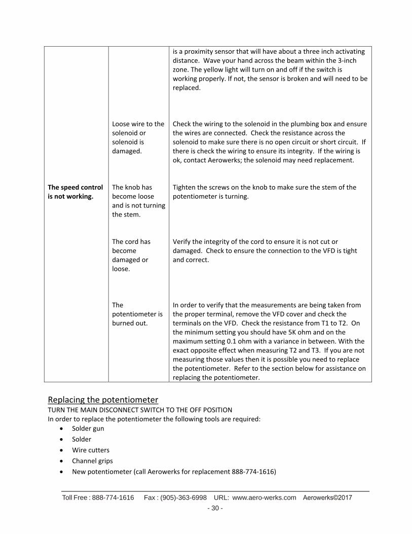
or water residue. Never direct a stream of water towards the switch. Water damage will either destroy the switch or cause false triggering. Check the anti‐jam switch located on the drive unit end of the slat belt to ensure it is not engaged. The anti‐jam will cause false triggers if the belt is too close to the arm. We require the arm be at least 1/8” from the belt across the belt width. Sometimes the magnetic sensor on the anti‐jam will not detect it has reset. In order to fix this simply press the anti‐jam rod all the way back then release it allowing it to hit the stopper. In rare cases there could be an issue with the magnetic sensor becoming misaligned. On the inside of the drive unit is a small magnetic sensor (as shown in the last anti‐jam picture under descriptions). This sensor can be moved by loosening the 7/16 nuts and moving it around till the trigger stops. **NOTE Aerowerks is not liable for any anti‐jam issues caused by the technician’s improper alignment. ** Check the sensor’s face to ensure it is not dirty or scratched. If it is dirty the sensor can be cleaned and should work properly. If it is scratched please contact Aerowerks for a replacement.
Remove the sensor from the fitting by removing the two Philips screws holding it in place. Flip the sensor over so we can observe the back of it as shown in the picture
below. The green light should be always on to indicate the sensor is receiving power. If the green light is not on then check the wiring to make sure power is being provided to the sensor. The yellow light indicates the sensor is detecting something. It
Toll Free : 888-774-1616 Fax : (905)-363-6998 URL: www.aero-werks.com
- 30 -
The speed control is not working.
Loose wire to the solenoid or solenoid is damaged. The knob has become loose and is not turning the stem. The cord has become damaged or loose. The potentiometer is burned out.
is a proximity sensor that will have about a three inch activating distance. Wave your hand across the beam within the 3‐inch zone. The yellow light will turn on and off if the switch is working properly. If not, the sensor is broken and will need to be replaced. Check the wiring to the solenoid in the plumbing box and ensure the wires are connected. Check the resistance across the solenoid to make sure there is no open circuit or short circuit. If there is check the wiring to ensure its integrity. If the wiring is ok, contact Aerowerks; the solenoid may need replacement. Tighten the screws on the knob to make sure the stem of the potentiometer is turning. Verify the integrity of the cord to ensure it is not cut or damaged. Check to ensure the connection to the VFD is tight and correct. In order to verify that the measurements are being taken from the proper terminal, remove the VFD cover and check the terminals on the VFD. Check the resistance from T1 to T2. On the minimum setting you should have 5K ohm and on the maximum setting 0.1 ohm with a variance in between. With the exact opposite effect when measuring T2 and T3. If you are not measuring those values then it is possible you need to replace the potentiometer. Refer to the section below for assistance on replacing the potentiometer.
Replacing the potentiometer TURN THE MAIN DISCONNECT SWITCH TO THE OFF POSITION In order to replace the potentiometer the following tools are required:
Solder gun
Solder
Wire cutters
Channel grips
New potentiometer (call Aerowerks for replacement 888‐774‐1616)
Toll Free : 888-774-1616 Fax : (905)-363-6998 URL: www.aero-werks.com
- 31 -
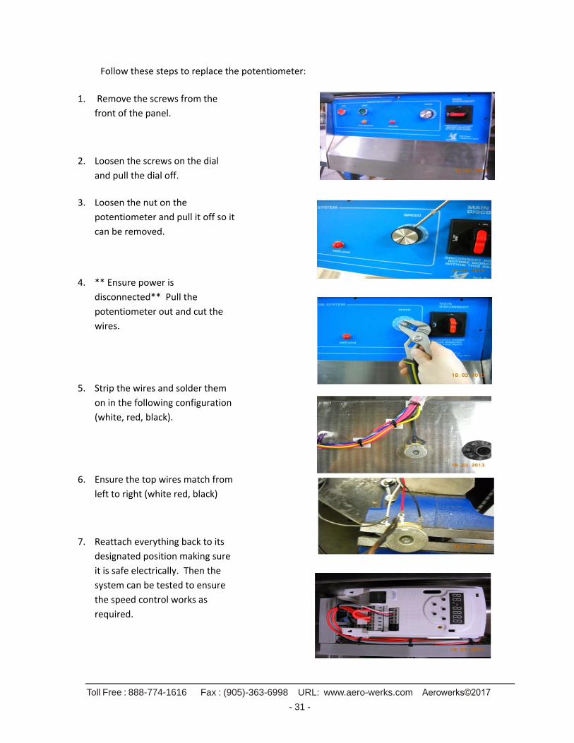
Follow these steps to replace the potentiometer:
1. Remove the screws from the
front of the panel.
2. Loosen the screws on the dial
and pull the dial off.
3. Loosen the nut on the
potentiometer and pull it off so it
can be removed.
4. ** Ensure power is
disconnected** Pull the
potentiometer out and cut the
wires.
5. Strip the wires and solder them
on in the following configuration
(white, red, black).
6. Ensure the top wires match from
left to right (white red, black)
7. Reattach everything back to its
designated position making sure
it is safe electrically. Then the
system can be tested to ensure
the speed control works as
required.
Toll Free: 1‐888‐774‐1616| Fax: (905) 363‐6998 |URL: www.aero‐werks.com Aerowerks©2017
32
DROP AREA LED LIGHTING
LED Lights are installed on top of the sound baffle and powered from Aerowerks control panel.
The LED light are rated for 24VDC only.
There is no separate switch for the LED lights, As soon as turn on the main disconnect the Led lights will turn on.
The tray drop area opening between 4’‐7’ ‐One LED light.
The tray drop area opening more than 8’‐two LED lights.
The LED length 1000mm, Natural White Unit 4000K and 11W.
6. WARRANTY:
AEROWERKS INC. LIMITED WARRANTY, SERVICE & PARTS POLICY 6.1 WARRANTY PERIOD
Aerowerks warrants its products to the original purchaser against any defects in material and
workmanship, under normal use and service for a period of one year after the date of
installation. Such installation must be performed by Aerowerks personnel or an Aerowerks
authorized agent.
6.2 GENERAL
Aerowerks will not cover for damage to electrical/mechanical equipment on conveyors due to
power surges, water damage (due to building plumbing leaks or improper equipment maintenance)
& electrical overloads.
Aerowerks is not liable for damage caused by faulty installation, mechanical or electrical failure
caused by unauthorized alteration, misuse or abuse of the equipment.
Liability or obligation in connection with the products of Aerowerks is limited to the products
covered in this warranty.
This warranty is exclusive and in lieu of any other warranty, either written or oral and whether
express or implied.
This warranty is limited to the United States and Canada.
In no event shall Aerowerks be liable for incidental, indirect or consequential damage whether
caused by use, misuse, or defects in the product.
6.3 CUSTOMER RESPONSIBILITY
In addition to complying with all suggested maintenance guidelines and instructions, owner’s obligation shall include but not be limited to: operating the equipment in accordance with the owner’s manual or any other additional instructions given at time of installation or in subsequent communications provided by Aerowerks or its authorized agent.
The owner shall exhibit reasonable care in the use, operation, maintenance and general upkeep of the
equipment.
Failure to comply with these requirements will void any applicable warranty.
Toll Free: 1‐888‐774‐1616| Fax: (905) 363‐6998 |URL: www.aero‐werks.com Aerowerks©2017
33
6.4 HOW TO HANDLE A WARRANTY CALL
Please contact Aerowerks Customer Support Staff at 1‐888‐774‐1616 ext. 0 for all concerns
regarding Aerowerks equipment. Hours of operation are 8:00 am to 4:30 pm EST.
6.5 Do not contact Hobart Service: Hobart Service is our authorized service agent and will only
perform warranty service with a valid purchase order and authorization from Aerowerks.
Contacting us directly will speed up the process of your warranty concern to minimize downtime. If
you require after hours emergency service then call Hobart Service. In the event that Hobart
Service has scheduled a service call without prior notification to Aerowerks they must notify
Aerowerks and request a valid purchase order from Aerowerks during our normal business hours
before invoicing Aerowerks.
Please Note: Aerowerks will cover the cost of the service call. If overtime is required or
requested, the extra charges will be the customer’s responsibility. The claim must be submitted to
Aerowerks immediately for validation. 6.6WARRANTY COVERAGE
It is important to follow the proper operation and maintenance procedures outlined in the service
manual, so that the new Aerowerks System will provide years of trouble‐free operation. Failure to
follow proper operating and maintenance procedures will void the warranty of your equipment. Please review complete system manual for operation, clean‐up and maintenance procedures.
The obligation of Aerowerks under this warranty is to repair or replace any defects in the
equipment. All the services covered under the warranty will be provided by Aerowerks during
regular working hours. All claims against this warranty must be made in writing to Aerowerks.
Equipment must be serviced by Aerowerks technicians or its authorized agent. All warranty parts
will be shipped to the client via regular ground transportation. Express or priority delivery will be
invoiced to the customer.
6.7 Slat Belt Conveyor
The following items are not covered under this warranty:
Conveyor Belt Slats: Over time, the plastic flights that transport dishware (commonly known as
slats) will wear, scratch and may break or separate from the chain. This is normal; replacement of
these slats is not covered under warranty. It is important that you do not operate your system
with broken or damaged slats. If a slat is partially damaged it should be removed completely.
Operating the system with more than 3 slats missing in a row may damage the conveyor. Keep
spare slats on hand for quick and easy replacement. If you notice extreme wear please contact
Aerowerks Customer service.
Slat Belt Jams: The slat belt is designed to lift out of the track without the use of tools for easy
cleaning. If, after cleaning or servicing, the belt is not inserted into the track properly the conveyor
will jam once started. This is the most common cause of conveyor jams and is not covered under
warranty.
It is important to train staff on the proper operation and clean‐up procedure of the SBC system. See
Toll Free: 1‐888‐774‐1616| Fax: (905) 363‐6998 |URL: www.aero‐werks.com Aerowerks©2017
34
Operation Manual.
Cutlery or Dishware Jams: The SBC System is designed with overlapping slats, beveled planes and
curved edges. These features are designed to minimize the chance of objects becoming wedged
between slats. The conveyor belt will generally safely handle individual dishware; however,
cutlery must be removed and placed on a tray or bus tub. Broken slats or incidental damage
caused by cutlery jams will not be replaced or repaired under warranty. Any other items (cleaning
cloths or equipment etc.) that may possibly cause a jam should be removed by staff.
Clogged Drains: Both the wash chamber in the SBC drive unit and tail tank have strainer baskets to
prevent foreign material from entering drain lines. These strainers must be emptied frequently.
Take care to insert the strainers correctly; they will slip into place easily. These service points are
located in the conveyor drive tank and tail tank of every SBC system.
Never run the conveyor with a missing strainer. It must be replaced immediately to avoid a clogged
drain line.
Clogged Solenoid Valves: Each SBC system comes with a pre‐installed Y‐Strainer designed to trap
particles that may damage the solenoid valve, if your solenoid valve gets clogged due to impurities
in the water supply we will not cover it under warranty. If your system proved to have a faulty
solenoid valve please contact Aerowerks customer service for a replacement.
Plumbing Leaks: The internal plumbing of each SBC is tested for leaks before it leaves the
factory. If a leak should occur on any plumbing done at the factory it will be repaired under
warranty.
Aerowerks will not cover any cost associated with repairing leaks from the building supply or
leaks occurring from any accessory equipment connected to the Aerowerks system.


![1 SERIES Belt Conveyor System B090 - Bett Sistemi Srl€¦ · CONVEYOR BELT DEVELOPMENT CALCULATION FORMULA Conveyor belt length = 300 + {[(L-94)-(2• Conveyor belt thick. )]•2}](https://img.pdfslide.net/doc/110x75/5ad3c4047f8b9a48398b7ae4/1-series-belt-conveyor-system-b090-bett-sistemi-conveyor-belt-development-calculation.jpg)