Embed Size (px)
Citation preview
ENMETENMET Corporation
PO Box 979Ann Arbor, MI 48106-0979
80003-141February 1999MCN-248, 01/22/01MCN-291, 10/21/03
Instruction ManualGas Sampling Unit
DC Operation

Table of Contents1.0 INTRODUCTION...................................................................................................................................................................................1
1.1 UNPACK .................................................................................................................................................................................................. 11.2 CHECK ORDER ....................................................................................................................................................................................... 11.3 SERIAL NUMBERS.................................................................................................................................................................................. 1
2.0 SPECIFICATIONS ................................................................................................................................................................................2
3.0 FEATURES AND FUNCTION...........................................................................................................................................................2
4.0 INSTALLATION ....................................................................................................................................................................................4
5.0 OPERATION...........................................................................................................................................................................................7
5.1 PROCEDURE FOR SAMPLING FROM GAS BAG .................................................................................................................................... 7
6.0 MAINTENANCE.....................................................................................................................................................................................9
6.1 PUMP MAINTENANCE FOR PUMP 04018-018..................................................................................................................................... 96.2 PUMP MAINTENANCE FOR PUMP 04018-118................................................................................................................................... 11
6.2.1 Pump Diaphragm Replacement ...............................................................................................................................................116.2.2 Check Valve Housing Replacement.........................................................................................................................................12
7.0 WARRANTY..........................................................................................................................................................................................13
List of Illustrations
FIGURE 1: GAS SAMPLING UNIT FEATURES ............................................................................................................................................. 3FIGURE 2: DIMENSIONAL DIAGRAM .......................................................................................................................................................... 4FIGURE 3: GAS SAMPLING UNIT WITH SENSOR/TRANSMITTER MOUNTED INTERNALLY .............................................................. 4FIGURE 4: APPLICATION, REMOTE SENSOR, MOTORIZED SAMPLE DRAW SYSTEM ...................................................................... 5FIGURE 5: WIRING DIAGRAM GAS SAMPLING UNIT WITH RX-1G CONTROL................................................................................. 6FIGURE 6: FILLING SAMPLE BAG FROM GAS CYLINDER ...................................................................................................................... 7FIGURE 7: VENTING CALIBRATION GAS TO A GAS BAG........................................................................................................................ 8FIGURE 8: VENTING CALIBRATION GAS TO AN EXHAUST LINE........................................................................................................... 8FIGURE 9: 04018-018 PUMP FEATURES ..................................................................................................................................................... 9FIGURE 10: 04018-118 PUMP FEATURES ................................................................................................................................................. 11FIGURE 11: DIAPHRAGM DETAILS............................................................................................................................................................ 11FIGURE 12: CHECK VALVE HOUSING REPLACEMENT DETAILS ........................................................................................................ 12FIGURE 13: PROPER ORIENTATION OF CHECK VALVE HOUSING AND GASKET............................................................................ 12
Reference information:NOTE: [important information about use of instrument – if not followed may have to redo some steps.]
CAUTION: [affects equipment – if not followed may cause damage to instrument, sensor etc…]
WARNING: [affects personnel safety – if not followed may cause bodily injury or death.]

Gas Sampling Unit ENMET Corporation
1
1.0 Introduction1.0 IntroductionThe ENMET gas sampling unit is used in applications requiring air sample draw to a sensor. It is designed to be usedin conjunction with ENMET sensor/transmitters. If used with other manufactures’ sensor/transmitters, contact yourlocal ENMET representative or ENMET
NOTE: All specifications stated in this manual may change without notice.
1.1 UnpackUnpack the Gas Sampling Unit and examine it for shipping damage. If such damage is observed, notify both ENMETcustomer service personnel and the commercial carrier involved immediately.
Regarding Damaged Shipments
NOTE: It is your responsibility to follow these instructions. If they are not followed, the carrier willnot honor any claims for damage.q This shipment was carefully inspected, verified and properly packaged at our company and delivered to the
carrier in good condition.
q When it was picked up by the carrier at ENMET, it legally became your company’s property.
q If your shipment arrives damaged:
• Keep the items, packing material, and carton “As Is.” Within 5 days of receipt, notify the carrier’s localoffice and request immediate inspection of the carton and the contents.
• After the inspection and after you have received written acknowledgment of the damage from the carrier,contact ENMET Customer Service for return authorization and further instructions. Have your PurchaseOrder and Sales Order numbers available.
q ENMET either repairs or replaces damaged equipment and invoices the carrier to the extent of the liabilitycoverage, usually $100.00. Repair or replacement charges above that value are your company’s responsibility.
q The shipping company may offer optional insurance coverage. ENMET only insures shipments with theshipping company when asked to do so in writing by our customer. If you need your shipments insured, pleaseforward a written request to ENMET Customer Service.
Regarding ShortagesIf there are any shortages or questions regarding this shipment, please notify ENMET Customer Service within 5 daysof receipt at the following address:
ENMET Corporation680 Fairfield Court
Ann Arbor, MI 48108734-761-1270 734-761-3220 Fax
1.2 Check OrderCheck, against the purchase order. Verify that the Gas Sampling Unit is received as ordered. If there are accessorieson the order, ascertain that they are present. Notify ENMET customer service personnel of any discrepancyimmediately.
1.3 Serial NumbersEach Gas Sampling Unit is serialized. These numbers are on tags on the equipment and are on record in an ENMETdatabase.
ENMET Corporation Gas Sampling Unit
2
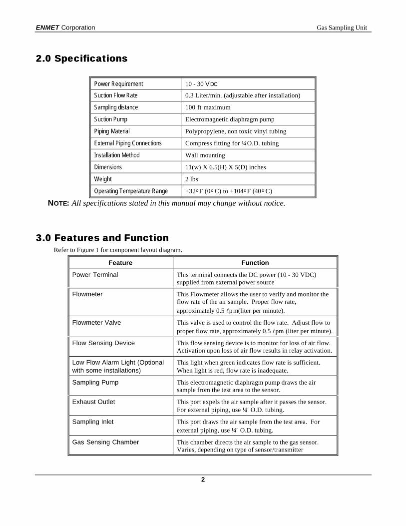
2.0 Specifications2.0 Specifications
Power Requirement 10 - 30 VDC
Suction Flow Rate 0.3 Liter/min. (adjustable after installation)
Sampling distance 100 ft maximum
Suction Pump Electromagnetic diaphragm pump
Piping Material Polypropylene, non toxic vinyl tubing
External Piping Connections Compress fitting for ¼ O.D. tubing
Installation Method Wall mounting
Dimensions 11(w) X 6.5(H) X 5(D) inches
Weight 2 lbs
Operating Temperature Range +32ºF (0ºC) to +104ºF (40ºC)
NOTE: All specifications stated in this manual may change without notice.
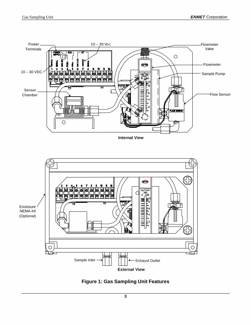
3.0 Features and Function3.0 Features and FunctionRefer to Figure 1 for component layout diagram.
Feature Function
Power Terminal This terminal connects the DC power (10 - 30 VDC)supplied from external power source
Flowmeter This Flowmeter allows the user to verify and monitor theflow rate of the air sample. Proper flow rate,approximately 0.5 lp m(liter per minute).
Flowmeter Valve This valve is used to control the flow rate. Adjust flow toproper flow rate, approximately 0.5 lpm (liter per minute).
Flow Sensing Device This flow sensing device is to monitor for loss of air flow.Activation upon loss of air flow results in relay activation.
Low Flow Alarm Light (Optionalwith some installations)
This light when green indicates flow rate is sufficient.When light is red, flow rate is inadequate.
Sampling Pump This electromagnetic diaphragm pump draws the airsample from the test area to the sensor.
Exhaust Outlet This port expels the air sample after it passes the sensor.For external piping, use ¼″ O.D. tubing.
Sampling Inlet This port draws the air sample from the test area. Forexternal piping, use ¼″ O.D. tubing.
Gas Sensing Chamber This chamber directs the air sample to the gas sensor.Varies, depending on type of sensor/transmitter
Gas Sampling Unit ENMET Corporation
3
Internal View
External View
Figure 1: Gas Sampling Unit Features
EnclosureNEMA-4X(Optional)
Exhaust OutletSample Inlet
Flow Sensor
Flowmeter
FlowmeterValve
PowerTerminals
10 – 30 VDC
SensorChamber
Sample Pump
10 – 30 VDC
ENMET Corporation Gas Sampling Unit
4
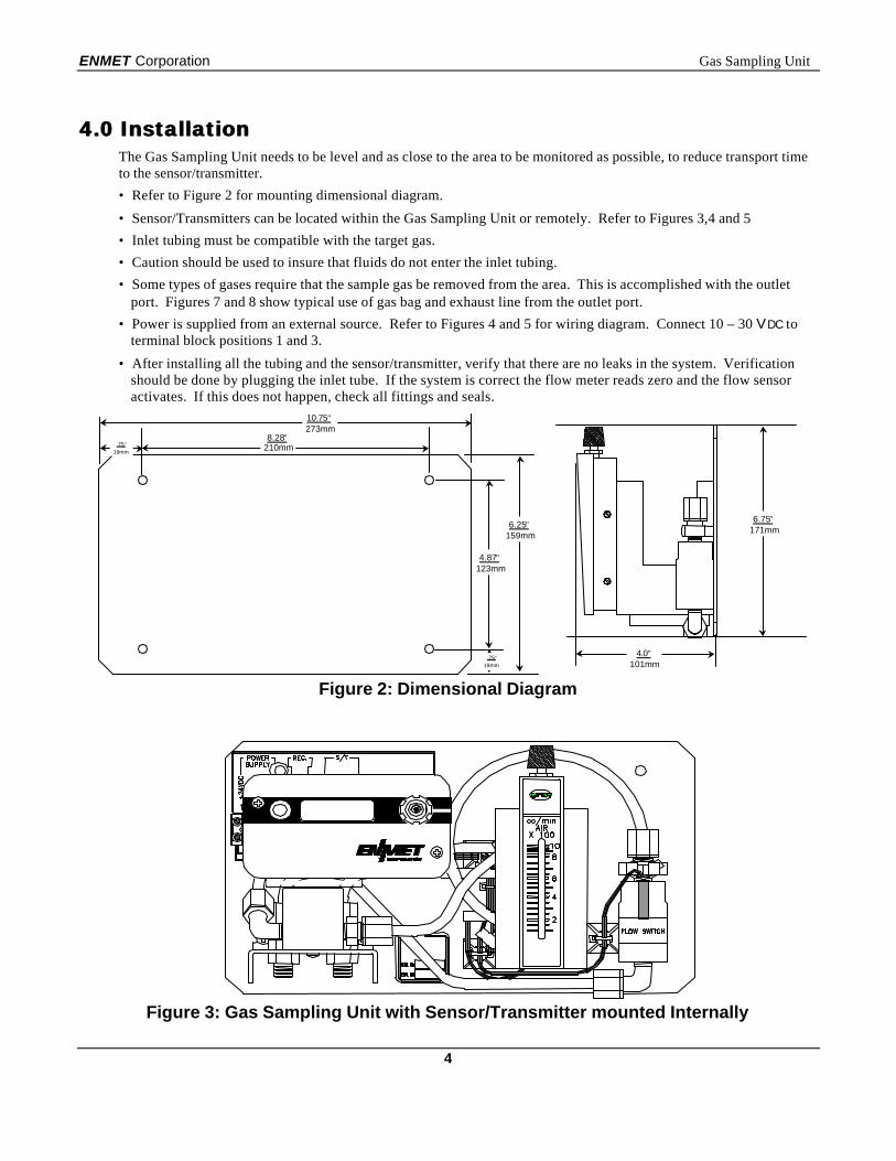
4.0 Installation4.0 InstallationThe Gas Sampling Unit needs to be level and as close to the area to be monitored as possible, to reduce transport timeto the sensor/transmitter.
• Refer to Figure 2 for mounting dimensional diagram.
• Sensor/Transmitters can be located within the Gas Sampling Unit or remotely. Refer to Figures 3,4 and 5
• Inlet tubing must be compatible with the target gas.
• Caution should be used to insure that fluids do not enter the inlet tubing.
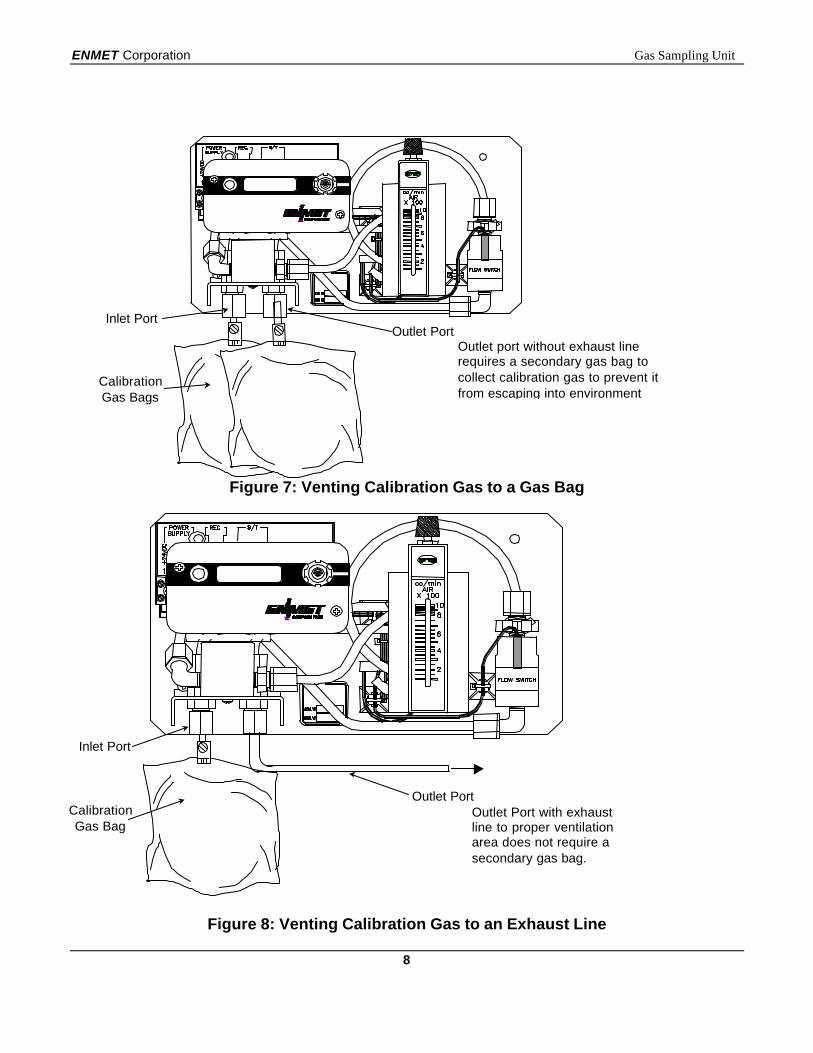
• Some types of gases require that the sample gas be removed from the area. This is accomplished with the outletport. Figures 7 and 8 show typical use of gas bag and exhaust line from the outlet port.
• Power is supplied from an external source. Refer to Figures 4 and 5 for wiring diagram. Connect 10 – 30 VDC toterminal block positions 1 and 3.
• After installing all the tubing and the sensor/transmitter, verify that there are no leaks in the system. Verificationshould be done by plugging the inlet tube. If the system is correct the flow meter reads zero and the flow sensoractivates. If this does not happen, check all fittings and seals.
Figure 2: Dimensional Diagram
Figure 3: Gas Sampling Unit with Sensor/Transmitter mounted Internally
10.75″273mm
4.87″123mm
.75″19mm
.75″19mm
8.28″210mm
6.25″159mm
6.75″171mm
4.0″101mm
Gas Sampling Unit ENMET Corporation
5
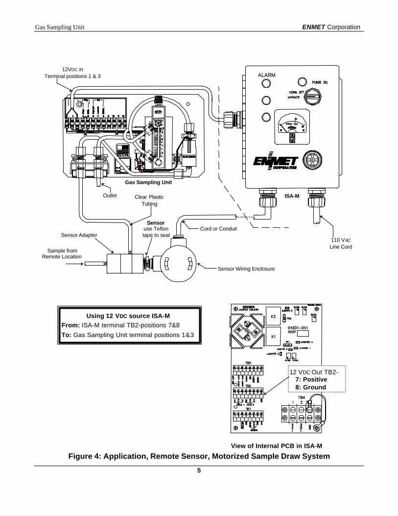
View of Internal PCB in ISA-M
Figure 4: Application, Remote Sensor, Motorized Sample Draw System
Using 12 VDC source ISA-MFrom: ISA-M terminal TB2-positions 7&8To: Gas Sampling Unit terminal positions 1&3
12 VDC Out TB2-7: Positive8: Ground
110 VAC
Line Cord
Outlet
Cord or Conduit
Clear PlasticTubing
Sample fromRemote Location
Sensor Wiring Enclosure
12VDC inTerminal positions 1 & 3
Gas Sampling Unit
ISA-M
Sensor Adapter
Sensoruse Teflontape to seal
ENMET Corporation Gas Sampling Unit
6
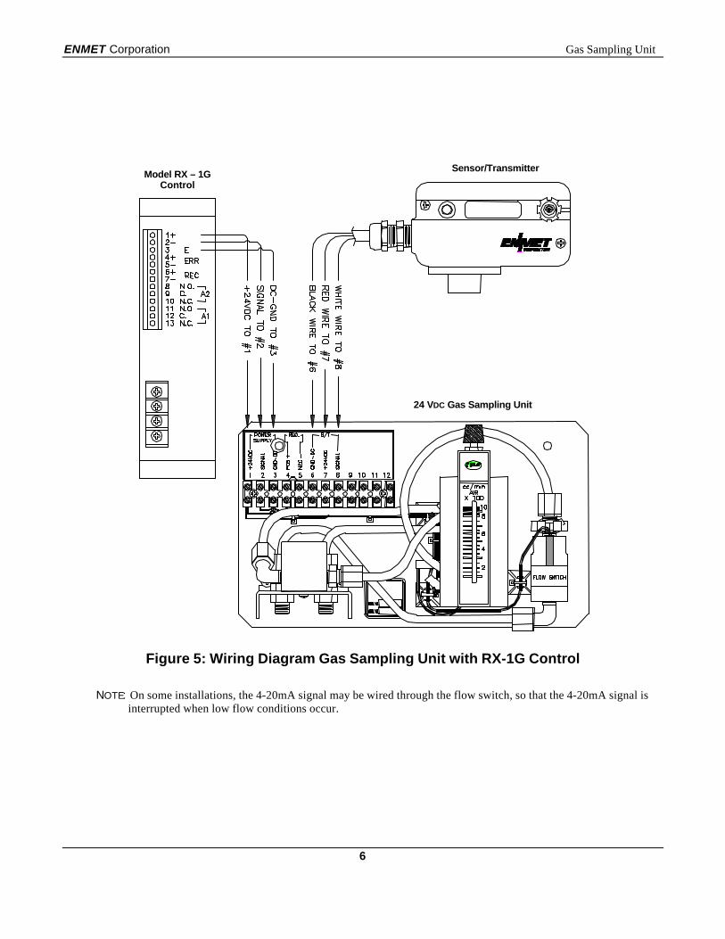
Figure 5: Wiring Diagram Gas Sampling Unit with RX-1G Control
NOTE: On some installations, the 4-20mA signal may be wired through the flow switch, so that the 4-20mA signal isinterrupted when low flow conditions occur.
Model RX – 1GControl
Sensor/Transmitter
24 VDC Gas Sampling Unit
Gas Sampling Unit ENMET Corporation
7
5.0 Operation5.0 OperationThe Gas Sampling Unit requires no calibration itself, however any sensor/transmitter or instrument associated with itdoes. Follow the instructions associated with the sensor/transmitter or instrument. To insure that the calibration isaccurate with the sample draw system, you need to fill a sample bag with calibration gas.
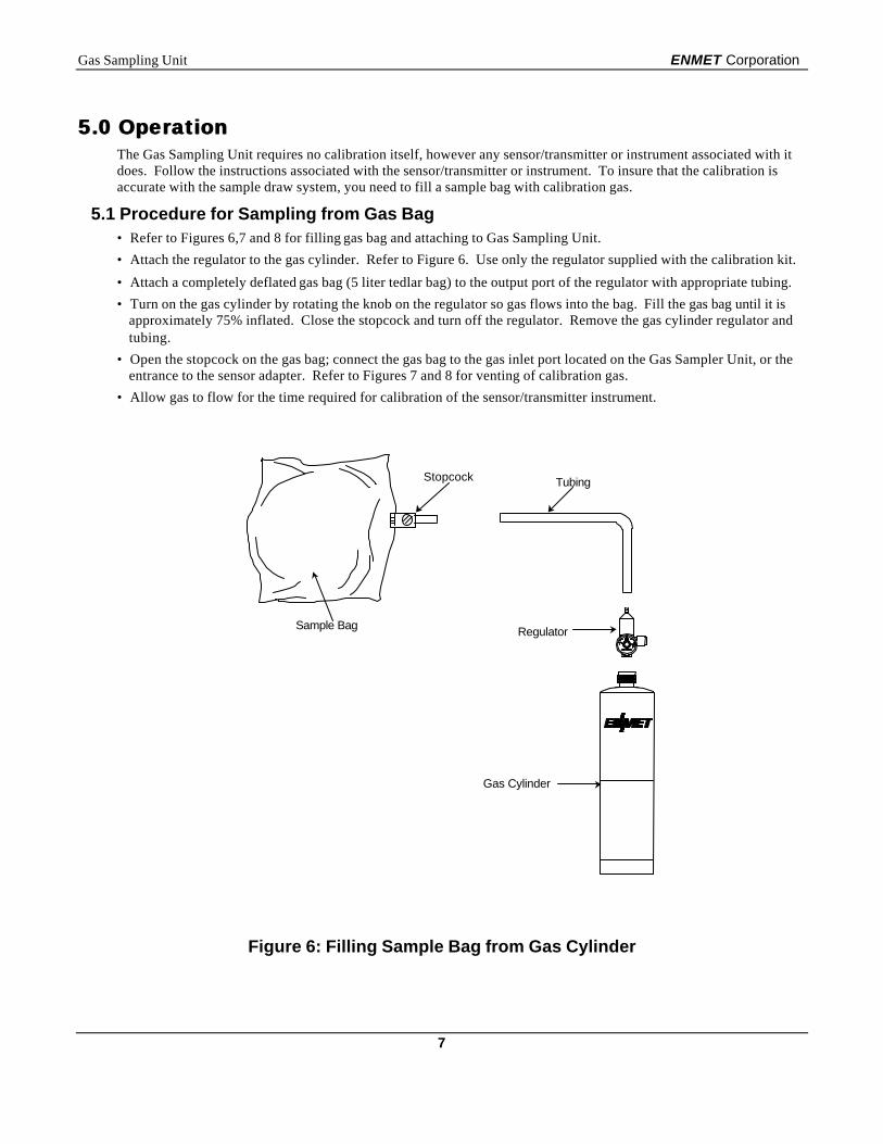
5.1 Procedure for Sampling from Gas Bag• Refer to Figures 6,7 and 8 for filling gas bag and attaching to Gas Sampling Unit.
• Attach the regulator to the gas cylinder. Refer to Figure 6. Use only the regulator supplied with the calibration kit.
• Attach a completely deflated gas bag (5 liter tedlar bag) to the output port of the regulator with appropriate tubing.
• Turn on the gas cylinder by rotating the knob on the regulator so gas flows into the bag. Fill the gas bag until it isapproximately 75% inflated. Close the stopcock and turn off the regulator. Remove the gas cylinder regulator andtubing.
• Open the stopcock on the gas bag; connect the gas bag to the gas inlet port located on the Gas Sampler Unit, or theentrance to the sensor adapter. Refer to Figures 7 and 8 for venting of calibration gas.
• Allow gas to flow for the time required for calibration of the sensor/transmitter instrument.
Figure 6: Filling Sample Bag from Gas Cylinder
Sample Bag
Tubing
Regulator
Gas Cylinder
Stopcock
ENMET Corporation Gas Sampling Unit
8
Figure 7: Venting Calibration Gas to a Gas Bag
Figure 8: Venting Calibration Gas to an Exhaust Line
Inlet PortOutlet Port
Outlet port without exhaust linerequires a secondary gas bag tocollect calibration gas to prevent itfrom escaping into environment
CalibrationGas Bags
Inlet Port
Outlet PortOutlet Port with exhaustline to proper ventilationarea does not require asecondary gas bag.
CalibrationGas Bag
Gas Sampling Unit ENMET Corporation
9
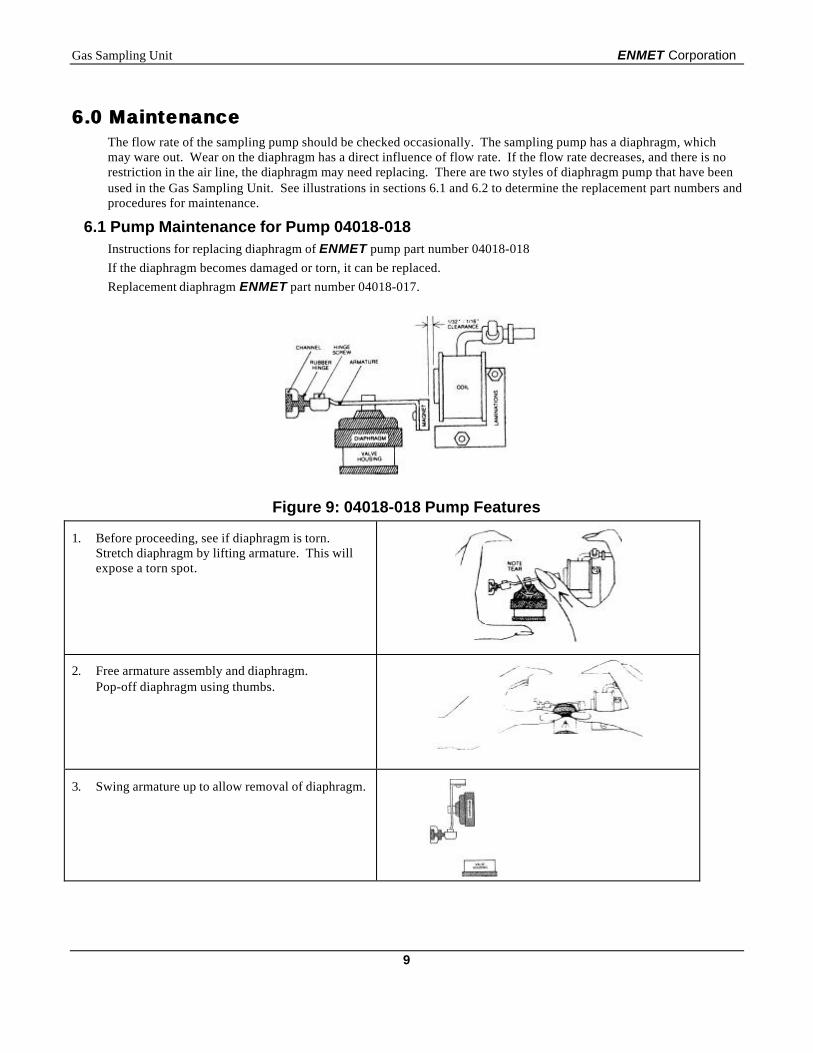
6.0 Maintenance6.0 MaintenanceThe flow rate of the sampling pump should be checked occasionally. The sampling pump has a diaphragm, whichmay ware out. Wear on the diaphragm has a direct influence of flow rate. If the flow rate decreases, and there is norestriction in the air line, the diaphragm may need replacing. There are two styles of diaphragm pump that have beenused in the Gas Sampling Unit. See illustrations in sections 6.1 and 6.2 to determine the replacement part numbers andprocedures for maintenance.
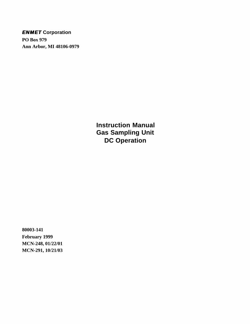
6.1 Pump Maintenance for Pump 04018-018Instructions for replacing diaphragm of ENMET pump part number 04018-018
If the diaphragm becomes damaged or torn, it can be replaced.
Replacement diaphragm ENMET part number 04018-017.
Figure 9: 04018-018 Pump Features
1. Before proceeding, see if diaphragm is torn.Stretch diaphragm by lifting armature. This willexpose a torn spot.
2. Free armature assembly and diaphragm.Pop-off diaphragm using thumbs.
3. Swing armature up to allow removal of diaphragm.
ENMET Corporation Gas Sampling Unit
10
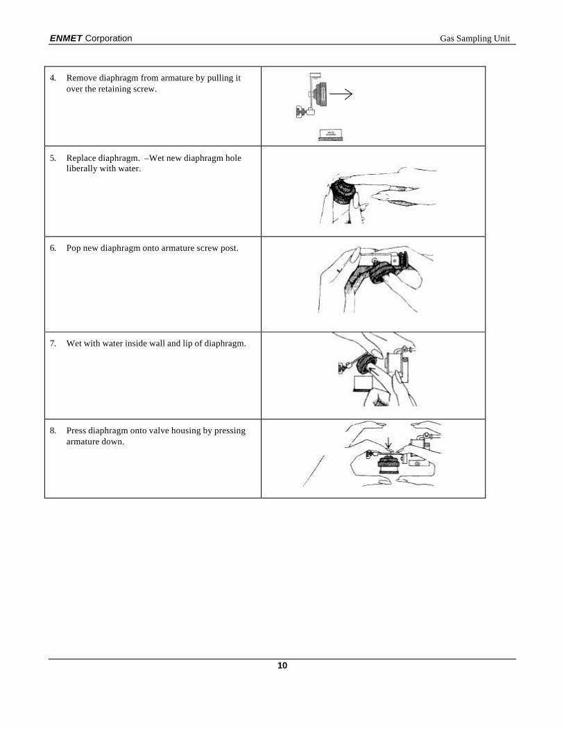
4. Remove diaphragm from armature by pulling itover the retaining screw.
5. Replace diaphragm. –Wet new diaphragm holeliberally with water.
6. Pop new diaphragm onto armature screw post.
7. Wet with water inside wall and lip of diaphragm.
8. Press diaphragm onto valve housing by pressingarmature down.
Gas Sampling Unit ENMET Corporation
11
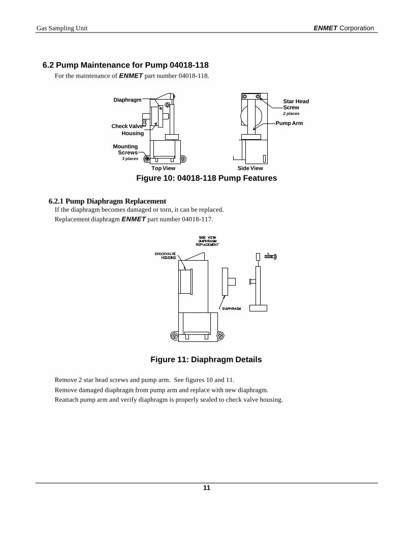
6.2 Pump Maintenance for Pump 04018-118For the maintenance of ENMET part number 04018-118.
Top View Side View
Figure 10: 04018-118 Pump Features
6.2.1 Pump Diaphragm ReplacementIf the diaphragm becomes damaged or torn, it can be replaced.
Replacement diaphragm ENMET part number 04018-117.
Figure 11: Diaphragm Details
Remove 2 star head screws and pump arm. See figures 10 and 11.
Remove damaged diaphragm from pump arm and replace with new diaphragm.
Reattach pump arm and verify diaphragm is properly sealed to check valve housing.
Pump ArmCheck ValveHousing
Diaphragm
MountingScrews
3 places
Star HeadScrew2 places
ENMET Corporation Gas Sampling Unit
12
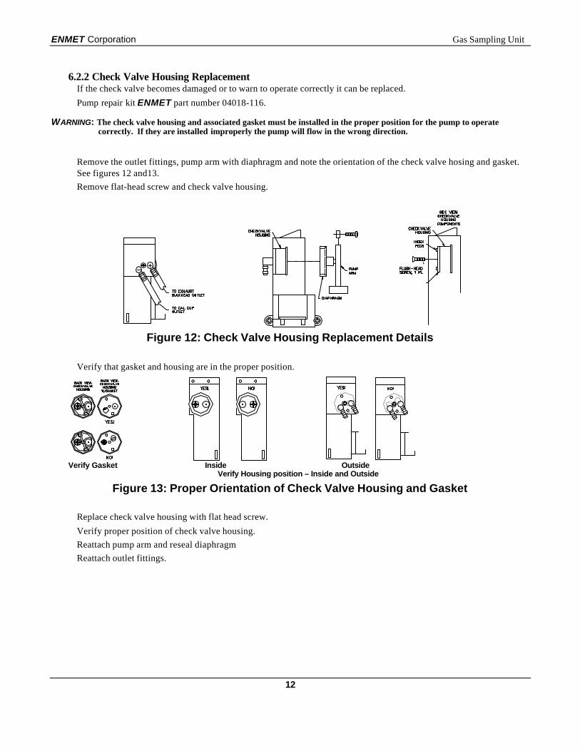
6.2.2 Check Valve Housing ReplacementIf the check valve becomes damaged or to warn to operate correctly it can be replaced.
Pump repair kit ENMET part number 04018-116.
WARNING: The check valve housing and associated gasket must be installed in the proper position for the pump to operatecorrectly. If they are installed improperly the pump will flow in the wrong direction.
Remove the outlet fittings, pump arm with diaphragm and note the orientation of the check valve hosing and gasket.See figures 12 and13.
Remove flat-head screw and check valve housing.
Figure 12: Check Valve Housing Replacement Details
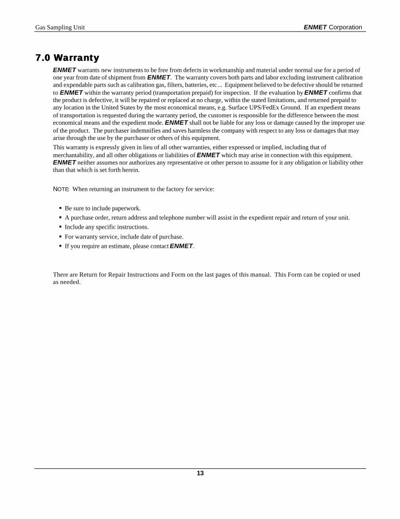
Verify that gasket and housing are in the proper position.
Verify Gasket Inside OutsideVerify Housing position – Inside and Outside
Figure 13: Proper Orientation of Check Valve Housing and Gasket
Replace check valve housing with flat head screw.
Verify proper position of check valve housing.
Reattach pump arm and reseal diaphragm
Reattach outlet fittings.
Gas Sampling Unit ENMET Corporation
13
7.0 Warranty7.0 WarrantyENMET warrants new instruments to be free from defects in workmanship and material under normal use for a period ofone year from date of shipment from ENMET. The warranty covers both parts and labor excluding instrument calibrationand expendable parts such as calibration gas, filters, batteries, etc... Equipment believed to be defective should be returnedto ENMET within the warranty period (transportation prepaid) for inspection. If the evaluation by ENMET confirms thatthe product is defective, it will be repaired or replaced at no charge, within the stated limitations, and returned prepaid toany location in the United States by the most economical means, e.g. Surface UPS/FedEx Ground. If an expedient meansof transportation is requested during the warranty period, the customer is responsible for the difference between the mosteconomical means and the expedient mode. ENMET shall not be liable for any loss or damage caused by the improper useof the product. The purchaser indemnifies and saves harmless the company with respect to any loss or damages that mayarise through the use by the purchaser or others of this equipment.
This warranty is expressly given in lieu of all other warranties, either expressed or implied, including that ofmerchantability, and all other obligations or liabilities of ENMET which may arise in connection with this equipment.ENMET neither assumes nor authorizes any representative or other person to assume for it any obligation or liability otherthan that which is set forth herein.
NOTE: When returning an instrument to the factory for service:
§ Be sure to include paperwork.
§ A purchase order, return address and telephone number will assist in the expedient repair and return of your unit.
§ Include any specific instructions.
§ For warranty service, include date of purchase.
§ If you require an estimate, please contact ENMET.
There are Return for Repair Instructions and Form on the last pages of this manual. This Form can be copied or usedas needed.

ENMET Corporation Gas Sampling Unit
14
Notes:
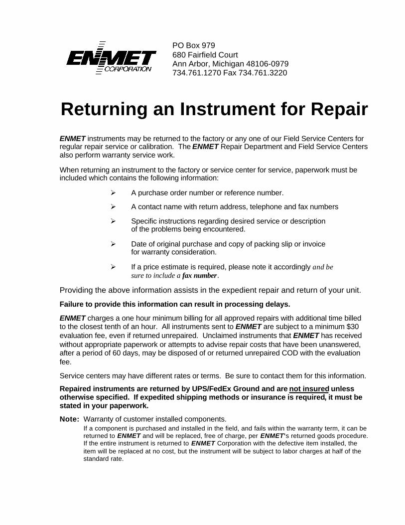
PO Box 979680 Fairfield CourtAnn Arbor, Michigan 48106-0979734.761.1270 Fax 734.761.3220
Returning an Instrument for RepairENMET instruments may be returned to the factory or any one of our Field Service Centers forregular repair service or calibration. The ENMET Repair Department and Field Service Centersalso perform warranty service work.
When returning an instrument to the factory or service center for service, paperwork must beincluded which contains the following information:
Ø A purchase order number or reference number.
Ø A contact name with return address, telephone and fax numbers
Ø Specific instructions regarding desired service or descriptionof the problems being encountered.
Ø Date of original purchase and copy of packing slip or invoicefor warranty consideration.
Ø If a price estimate is required, please note it accordingly and besure to include a fax number.
Providing the above information assists in the expedient repair and return of your unit.
Failure to provide this information can result in processing delays.
ENMET charges a one hour minimum billing for all approved repairs with additional time billedto the closest tenth of an hour. All instruments sent to ENMET are subject to a minimum $30evaluation fee, even if returned unrepaired. Unclaimed instruments that ENMET has receivedwithout appropriate paperwork or attempts to advise repair costs that have been unanswered,after a period of 60 days, may be disposed of or returned unrepaired COD with the evaluationfee.
Service centers may have different rates or terms. Be sure to contact them for this information.
Repaired instruments are returned by UPS/FedEx Ground and are not insured unlessotherwise specified. If expedited shipping methods or insurance is required, it must bestated in your paperwork.
Note: Warranty of customer installed components.If a component is purchased and installed in the field, and fails within the warranty term, it can bereturned to ENMET and will be replaced, free of charge, per ENMET’s returned goods procedure.If the entire instrument is returned to ENMET Corporation with the defective item installed, theitem will be replaced at no cost, but the instrument will be subject to labor charges at half of thestandard rate.

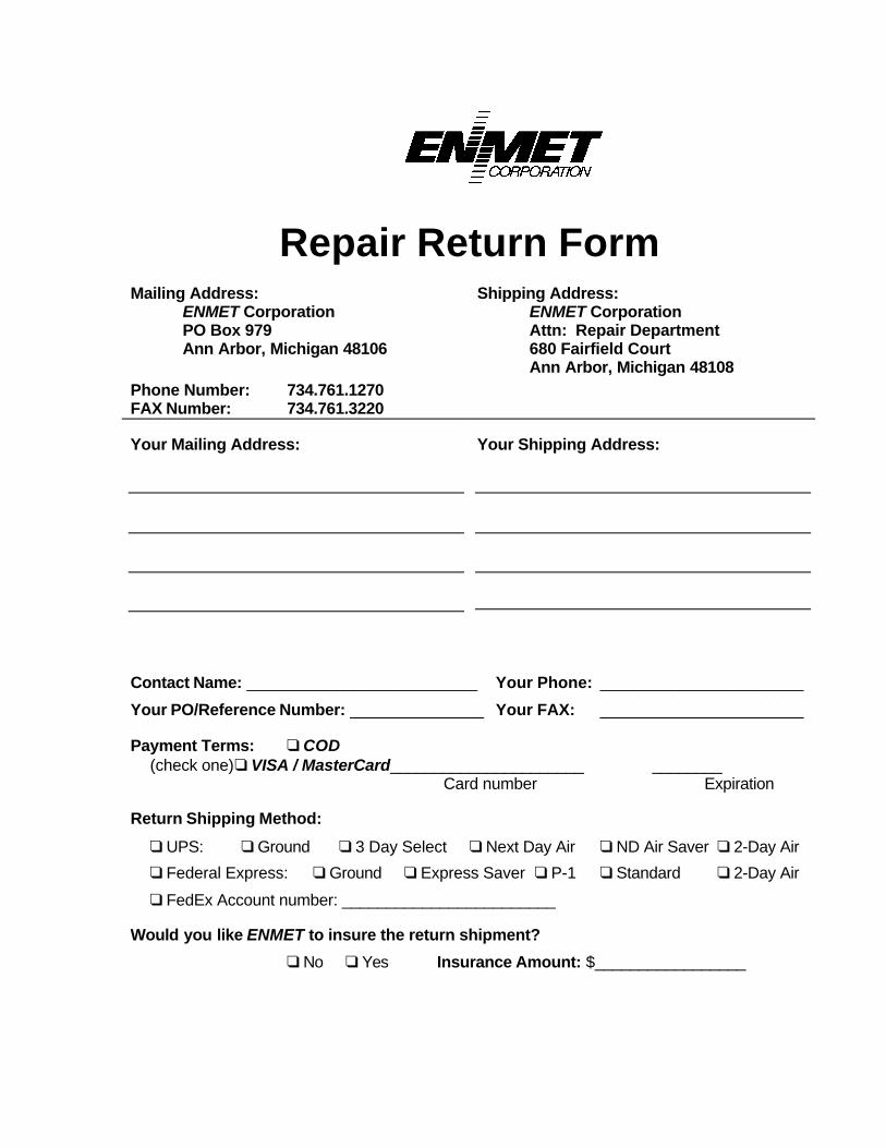
Repair Return FormMailing Address:
ENMET CorporationPO Box 979Ann Arbor, Michigan 48106
Phone Number: 734.761.1270FAX Number: 734.761.3220
Shipping Address:ENMET CorporationAttn: Repair Department680 Fairfield CourtAnn Arbor, Michigan 48108
Your Mailing Address: Your Shipping Address:
Contact Name: __________________________ Your Phone: _______________________
Your PO/Reference Number: _______________ Your FAX: _______________________
Payment Terms: q COD(check one)q VISA / MasterCard______________________ ________
Card number Expiration
Return Shipping Method:
q UPS: q Ground q 3 Day Select q Next Day Air q ND Air Saver q 2-Day Air
q Federal Express: q Ground q Express Saver q P-1 q Standard q 2-Day Air
q FedEx Account number: ________________________
Would you like ENMET to insure the return shipment?
q No q Yes Insurance Amount: $_________________