Embed Size (px)
Citation preview
Instruction ManualSLUICE GATES, AND SLIDE GATES
THIS MANUAL SHOULD BE READ CAREFULLY BEFORE INSTALLATION,OPERATION, AND MAINTENANCE OF RODNEY HUNT EQUIPMENT
®
TABLE OF CONTENTSPage
Note: This on-line publication is essentially similar to Rodney Hunt Company's standard “Instruction Manual” publication #WCE 82-4. The following formatting changes have been made which differ from the available hard-copy of this publication: Glydaseal Gate Information has been removed; photos not necessary to these instructions have been removed; the remaining pages have been renumbered; and the Table of Contents has been revised to reflect these changes.
Introduction…………………………………………..3
Handling and Storage……………………………… 4
Sluice Gate Installation…………………………5,6,7
Hy-Q Sluice Gate………………………………….7,8
Conventional Sluice Gate………………………… 9
Field Adjustment………………………………..10,11
Slide Gate Installation……………………………..12
Operating Mechanisms………………………..13,14
Pipe Covers, Indicators…………………………... 15
Stems and Stem Guides…………………………. 16
Operating Sluice Gates…………………………...17
Operating Slide Gates……………………………. 18
Trouble Shooting Tips, SluiceGates……...19,20,21
Trouble Shooting Tips, Slide Gates…………….. 22
Maintenance………………………………………. 23
General Notes…………………………………….. 24
Field Service Policy……………………………..…25
The information herein, is to our knowledge, true and accurate however, Rodney Hunt Company makes no warranties or representation, expressed or implied, other than those set forth in the specifications of a formal quotation. No agent representative or employee of this company is authorized to vary the terms of this notice.
®
2

Introduction
This manual describes the recommended methods of installation, adjustment, initial operations, maintenance and safety precautions for Rodney Hunt sluice gates, slide gates, operating mechanisms and related equipment. It should be used in conjunction with approved drawings provided by the Rodney Hunt Company.
The information in this manual pertains to most Rodney Hunt gates. However, there are special installations which require more specific information. In these cases a special set of instructions is forwarded to the gate user before installation.
Rodney Hunt sluice gates have been designed and manufactured to result in a nearly watertight closure. Before leaving the Rodney Hunt plant, equipment is inspected and the gate wedges are properly adjusted.
These precautions result in gates with low leakage characteristics. However, great care must be used in the handling, storage and installation of Rodney Hunt sluice gates to insure that they will operate as designed, and with maximum watertightness.
Rodney Hunt slide gates have also been designed and manufactured to meet your specific requirements.
The information in this manual is intended only as a recommendation for the proper and satisfactory installation of our equipment. Rodney Hunt Company assumes no liability, expressed or implied, for the interpretation of the recommendations or the faulty installation of the gates. Its responsibility is limited to defects in manufacturing rather than installation, adjustment and related problems subsequent to manufacturing.
®
3
Handling and Storage
For Safety
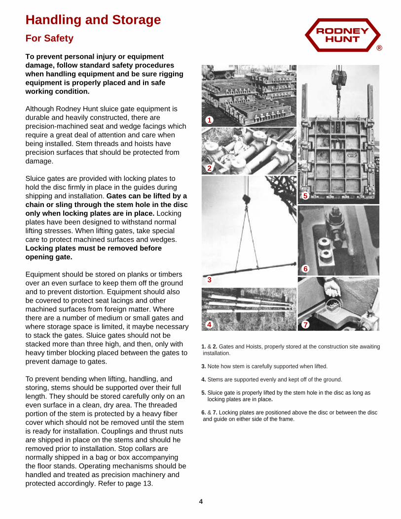
To prevent personal injury or equipment damage, follow standard safety procedures when handling equipment and be sure rigging equipment is properly placed and in safe working condition.
Although Rodney Hunt sluice gate equipment is durable and heavily constructed, there are precision-machined seat and wedge facings which require a great deal of attention and care when being installed. Stem threads and hoists have precision surfaces that should be protected from damage.
Sluice gates are provided with locking plates to hold the disc firmly in place in the guides during shipping and installation. Gates can be lifted by a chain or sling through the stem hole in the disc only when locking plates are in place. Locking plates have been designed to withstand normal lifting stresses. When lifting gates, take special care to protect machined surfaces and wedges. Locking plates must be removed before opening gate.
Equipment should be stored on planks or timbers over an even surface to keep them off the ground and to prevent distortion. Equipment should also be covered to protect seat lacings and other machined surfaces from foreign matter. Where there are a number of medium or small gates and where storage space is limited, it maybe necessary to stack the gates. Sluice gates should not be stacked more than three high, and then, only with heavy timber blocking placed between the gates to prevent damage to gates.
To prevent bending when lifting, handling, and storing, stems should be supported over their full length. They should be stored carefully only on an even surface in a clean, dry area. The threaded portion of the stem is protected by a heavy fiber cover which should not be removed until the stem is ready for installation. Couplings and thrust nuts are shipped in place on the stems and should he removed prior to installation. Stop collars are normally shipped in a bag or box accompanying the floor stands. Operating mechanisms should be handled and treated as precision machinery and protected accordingly. Refer to page 13.
1. & 2. Gates and Hoists, properly stored at the construction site awaiting installation.
3. Note how stem is carefully supported when lifted.
4. Stems are supported evenly and kept off of the ground.
5. .
6. & 7.
Sluice gate is properly lifted by the stem hole in the disc as long as locking plates are in place
Locking plates are positioned above the disc or between the disc and guide on either side of the frame.
®
4
1
4
3
2
6
5
7
Installation
Items Embedded in Concrete -Wall Thimbles
The most important single aspect of a sluice gate installation is the correct placement of the embedded items in the concrete. If these embedded items are accurately and carefully located and held in place during the concrete pour, a proper sluice gate installation is practically assured.
1.The front face of all Rodney Hunt thimbles.... rectangular, square and circular. ... are marked on vertical and horizontal centerlines. The centerline marks are also placed on the outer edge of the mounting flange of the wall thimble so that they can be seen after the thimbles are bolted to the forms.
2.Wall thimbles should be set with the top mark up and top and bottom centerline marks plumb.
3.After being set at the proper elevation, the wall thimble must be internally braced to carry the weight of the concrete. Care should be used in placement of the braces so as not to distort the wall thimble. Gate attaching holes and hardware will be misaligned if the wall thimble is distorted.
4.The wall thimble should be firmly supported on the form. The studs and nuts furnished with the thimble can be used for bolting the thimble in place. Forms should be supported and stiffened against movement. If forms move they will distort the wall thimble mounting flange, and the sluice gate will leak.
5.The tapped holes in the face of the wall thimble must be plugged or capped to prevent concrete from entering the holes. Rodney Hunt furnishes wall thimbles with plastic caps in the ends of each tapped hole. These caps should be left in place until the thimble is cast in the concrete and the gate is prepared for installation. The caps are easily removed by puncturing with a screw driver.
6. Where the depth of the wall thimble and thickness of the wall are the same, care is taken to maintain the length of the thimble within acceptable tolerances. This prevents distortion of the forms or the necessity of blocking the area between the casting and the forms.
7. After the concrete has hardened and the forms removed, the front surface of the wall thimble should be thoroughly cleaned. Make sure to remove any concrete that has flowed onto the surface from the edges. Care should be taken to prevent damage to
machined surfaces. The front flange of each Rodney Hunt wall thimble is purposely oversized to minimize this problem.
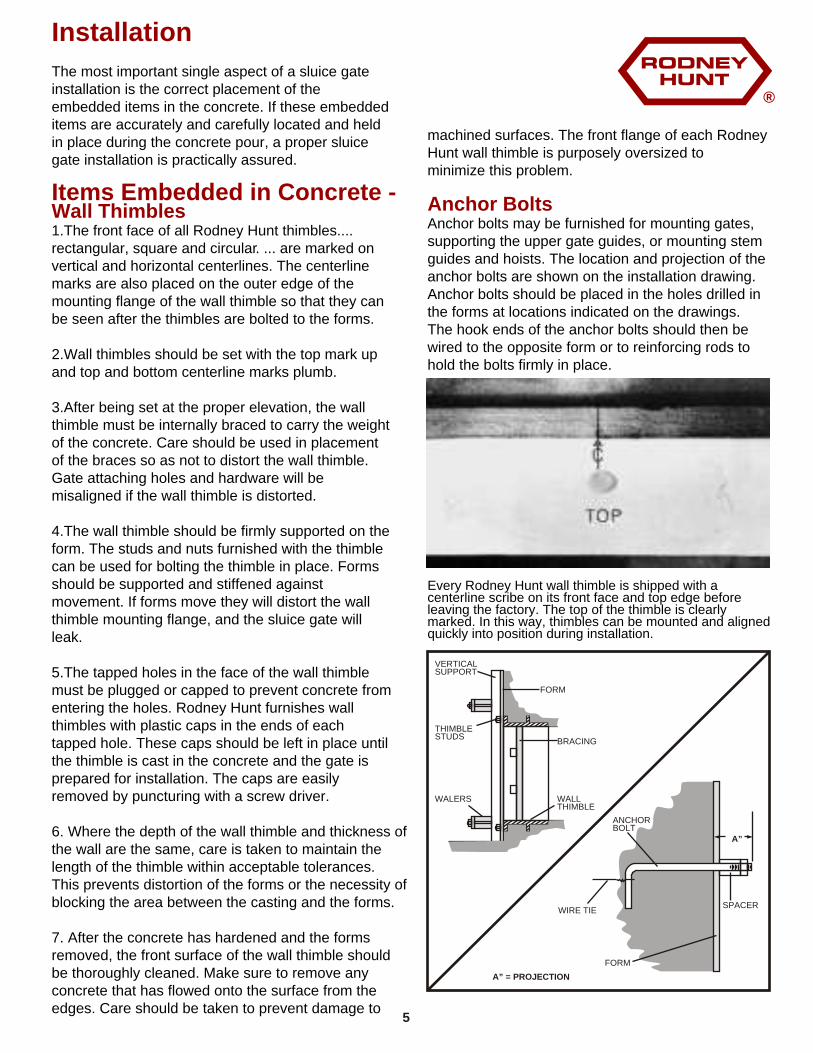
Anchor bolts may be furnished for mounting gates, supporting the upper gate guides, or mounting stem guides and hoists. The location and projection of the anchor bolts are shown on the installation drawing. Anchor bolts should be placed in the holes drilled in the forms at locations indicated on the drawings. The hook ends of the anchor bolts should then be wired to the opposite form or to reinforcing rods to hold the bolts firmly in place.
Anchor Bolts
Every Rodney Hunt wall thimble is shipped with a centerline scribe on its front face and top edge before leaving the factory. The top of the thimble is clearly marked. In this way, thimbles can be mounted and aligned quickly into position during installation.
VERTICALSUPPORT
THIMBLESTUDS
WALERS WALLTHIMBLE
BRACING
FORM
ANCHORBOLT
FORM
SPACER
A” = PROJECTION
WIRE TIE
A”
®
5
Sluice Gates
Installation On Wall Thimbles
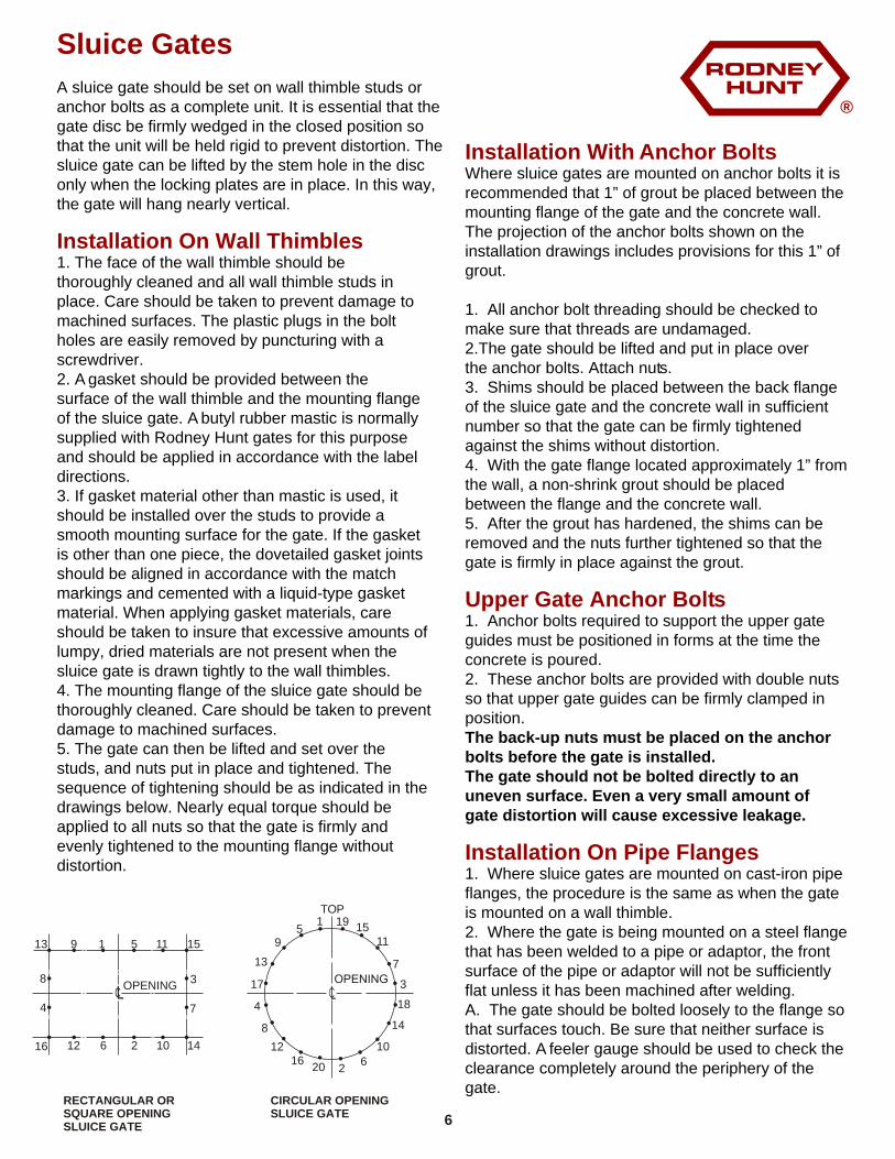
A sluice gate should be set on wall thimble studs or anchor bolts as a complete unit. It is essential that the gate disc be firmly wedged in the closed position so that the unit will be held rigid to prevent distortion. The sluice gate can be lifted by the stem hole in the disc only when the locking plates are in place. In this way, the gate will hang nearly vertical.
1. The face of the wall thimble should be thoroughly cleaned and all wall thimble studs in place. Care should be taken to prevent damage to machined surfaces. The plastic plugs in the bolt holes are easily removed by puncturing with a screwdriver.2. A gasket should be provided between the surface of the wall thimble and the mounting flange of the sluice gate. A butyl rubber mastic is normally supplied with Rodney Hunt gates for this purpose and should be applied in accordance with the label directions.3. If gasket material other than mastic is used, it should be installed over the studs to provide a smooth mounting surface for the gate. If the gasket is other than one piece, the dovetailed gasket joints should be aligned in accordance with the match markings and cemented with a liquid-type gasket material. When applying gasket materials, care should be taken to insure that excessive amounts of lumpy, dried materials are not present when the sluice gate is drawn tightly to the wall thimbles.4. The mounting flange of the sluice gate should be thoroughly cleaned. Care should be taken to prevent damage to machined surfaces.5. The gate can then be lifted and set over the studs, and nuts put in place and tightened. The sequence of tightening should be as indicated in the drawings below. Nearly equal torque should be applied to all nuts so that the gate is firmly and evenly tightened to the mounting flange without distortion.
Installation With Anchor BoltsWhere sluice gates are mounted on anchor bolts it is recommended that 1” of grout be placed between the mounting flange of the gate and the concrete wall. The projection of the anchor bolts shown on the installation drawings includes provisions for this 1” of grout.
1. All anchor bolt threading should be checked to make sure that threads are undamaged.2.The gate should be lifted and put in place over the anchor bolts. Attach nuts.3. Shims should be placed between the back flange of the sluice gate and the concrete wall in sufficient number so that the gate can be firmly tightened against the shims without distortion.4. With the gate flange located approximately 1” from the wall, a non-shrink grout should be placed between the flange and the concrete wall.5. After the grout has hardened, the shims can be removed and the nuts further tightened so that the gate is firmly in place against the grout.
1. Anchor bolts required to support the upper gate guides must be positioned in forms at the time the concrete is poured.2. These anchor bolts are provided with double nuts so that upper gate guides can be firmly clamped in position.The back-up nuts must be placed on the anchor bolts before the gate is installed.The gate should not be bolted directly to an uneven surface. Even a very small amount of gate distortion will cause excessive leakage.
1. Where sluice gates are mounted on cast-iron pipe flanges, the procedure is the same as when the gate is mounted on a wall thimble.2. Where the gate is being mounted on a steel flange that has been welded to a pipe or adaptor, the front surface of the pipe or adaptor will not be sufficiently flat unless it has been machined after welding.A. The gate should be bolted loosely to the flange so that surfaces touch. Be sure that neither surface is distorted. A feeler gauge should be used to check the clearance completely around the periphery of the gate.
Upper Gate Anchor Bolts
Installation On Pipe Flanges
CL
13 9 1 5 11 15
8 3
4 7
16 12 6 2 10 14
OPENING
1
2
3
4
5
6
7
8
9
10
11
12
13
14
15
16
17
18
19
20
TOP
RECTANGULAR ORSQUARE OPENINGSLUICE GATE
CIRCULAR OPENINGSLUICE GATE
®
6
B. Leakage may occur if the distortion is more than 0.010 when the two surfaces are bolted together.C. By using a thick fibrated mastic between surfaces, it may be possible to prevent leakage between flanges. In no case should the gate flange be firmly tightened against a flange that is not flat.D. If the spacing is very large, the gate should be shimmed a small distance away from the flange. Space between the flanges can be caulked with lead wool. This will allow the gate to be tightened to the steel flange without distortion or leakage between the flanges.
Consult the factory for assistance if the flange on which the gate is to be installed is not fIat and the gap between the gate flange and the mounting flange is excessive
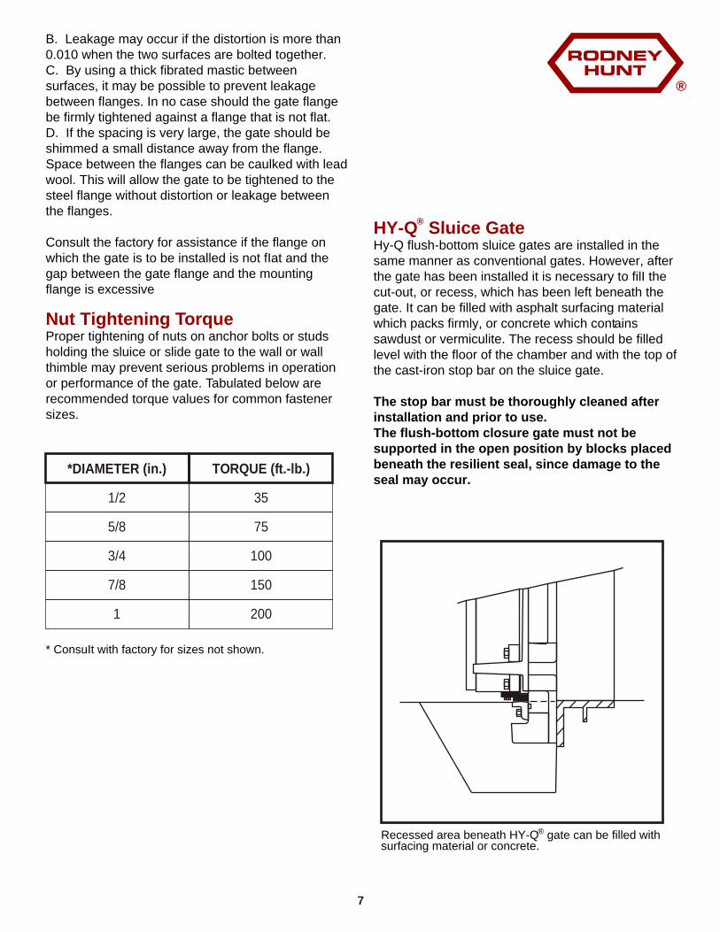
Proper tightening of nuts on anchor bolts or studs holding the sluice or slide gate to the wall or wall thimble may prevent serious problems in operation or performance of the gate. Tabulated below are recommended torque values for common fastener sizes.
* ConsuIt with factory for sizes not shown.
Nut Tightening Torque
*DIAMETER (in.)
1/2
5/8
3/4
7/8
1
TORQUE (ft.-lb.)
35
75
100
150
200
®Recessed area beneath HY-Q gate can be filled with surfacing material or concrete.
®
®HY-Q Sluice GateHy-Q flush-bottom sluice gates are installed in the same manner as conventional gates. However, after the gate has been installed it is necessary to filI the cut-out, or recess, which has been left beneath the gate. It can be filled with asphalt surfacing material which packs firmly, or concrete which contains sawdust or vermiculite. The recess should be filled level with the floor of the chamber and with the top of the cast-iron stop bar on the sluice gate.
The stop bar must be thoroughly cleaned after installation and prior to use.The flush-bottom closure gate must not be supported in the open position by blocks placed beneath the resilient seal, since damage to the seal may occur.
7
Hy-Q® Sluice Gate
Field Adjustment -HY-Q® Sluice Gates
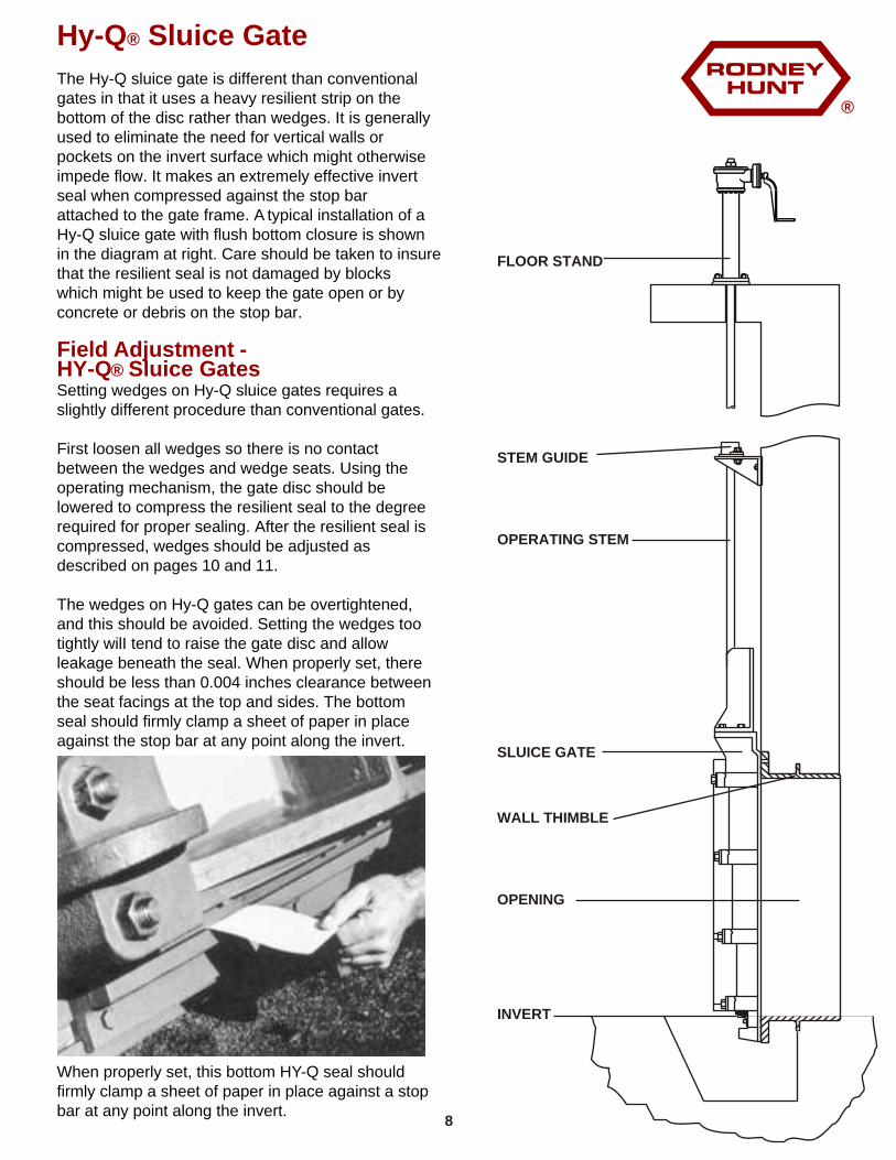
The Hy-Q sluice gate is different than conventional gates in that it uses a heavy resilient strip on the bottom of the disc rather than wedges. It is generally used to eliminate the need for vertical walls or pockets on the invert surface which might otherwise impede flow. It makes an extremely effective invert seal when compressed against the stop bar attached to the gate frame. A typical installation of a Hy-Q sluice gate with flush bottom closure is shown in the diagram at right. Care should be taken to insure that the resilient seal is not damaged by blocks which might be used to keep the gate open or by concrete or debris on the stop bar.
Setting wedges on Hy-Q sluice gates requires a slightly different procedure than conventional gates.
First loosen all wedges so there is no contact between the wedges and wedge seats. Using the operating mechanism, the gate disc should be lowered to compress the resilient seal to the degree required for proper sealing. After the resilient seal is compressed, wedges should be adjusted as described on pages 10 and 11.
The wedges on Hy-Q gates can be overtightened, and this should be avoided. Setting the wedges too tightly wilI tend to raise the gate disc and allow leakage beneath the seal. When properly set, there should be less than 0.004 inches clearance between the seat facings at the top and sides. The bottom seal should firmly clamp a sheet of paper in place against the stop bar at any point along the invert.
When properly set, this bottom HY-Q seal should firmly clamp a sheet of paper in place against a stop bar at any point along the invert.
FLOOR STAND
STEM GUIDE
OPERATING STEM
SLUICE GATE
WALL THIMBLE
OPENING
INVERT
®
8
®
Conventional Sluice Gates
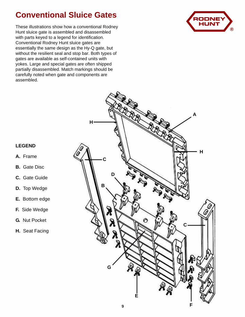
These illustrations show how a conventional Rodney Hunt sluice gate is assembled and disassembled with parts keyed to a Iegend for identification. Conventional Rodney Hunt sluice gates are essentially the same design as the Hy-Q gate, but without the resilient seal and stop bar. Both types of gates are available as self-contained units with yokes. Large and special gates are often shipped partially disassembled. Match markings should be carefully noted when gate and components are assembled.
LEGEND
A. Frame
B. Gate Disc
C. Gate Guide
D. Top Wedge
E. Bottom edge
F. Side Wedge
G. Nut Pocket
H. Seat Facing
A
B
C
D
E
F
G
H
C
H
9
®
Field Adjustment
Sluice Gates
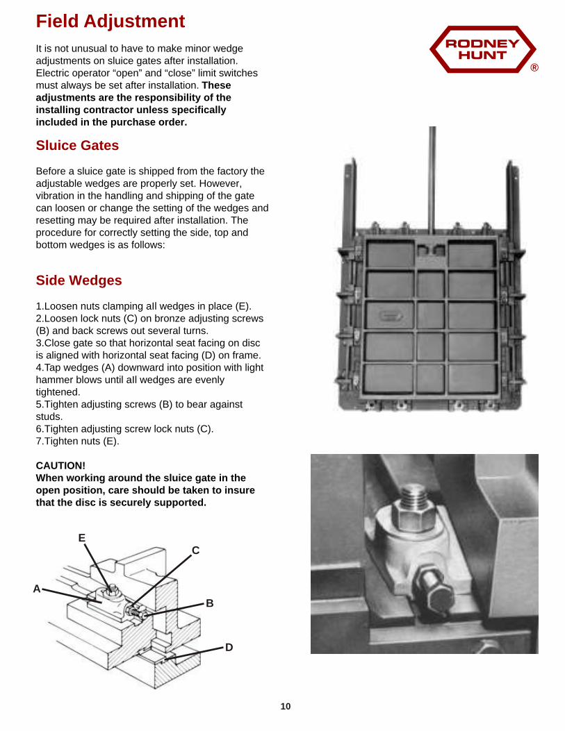
It is not unusual to have to make minor wedge adjustments on sluice gates after installation. Electric operator “open” and “close” limit switches must always be set after installation. These adjustments are the responsibility of the installing contractor unless specifically included in the purchase order.
Before a sluice gate is shipped from the factory the adjustable wedges are properly set. However, vibration in the handling and shipping of the gate can loosen or change the setting of the wedges and resetting may be required after installation. The procedure for correctly setting the side, top and bottom wedges is as follows:
1.Loosen nuts clamping aIl wedges in place (E).2.Loosen lock nuts (C) on bronze adjusting screws (B) and back screws out several turns.3.Close gate so that horizontal seat facing on disc is aligned with horizontal seat facing (D) on frame.4.Tap wedges (A) downward into position with lighthammer blows until aIl wedges are evenly tightened.5.Tighten adjusting screws (B) to bear against studs.6.Tighten adjusting screw lock nuts (C).7.Tighten nuts (E).
CAUTION!When working around the sluice gate in the open position, care should be taken to insure that the disc is securely supported.
Side Wedges
A
B
CE
D
10
®
Top Wedges
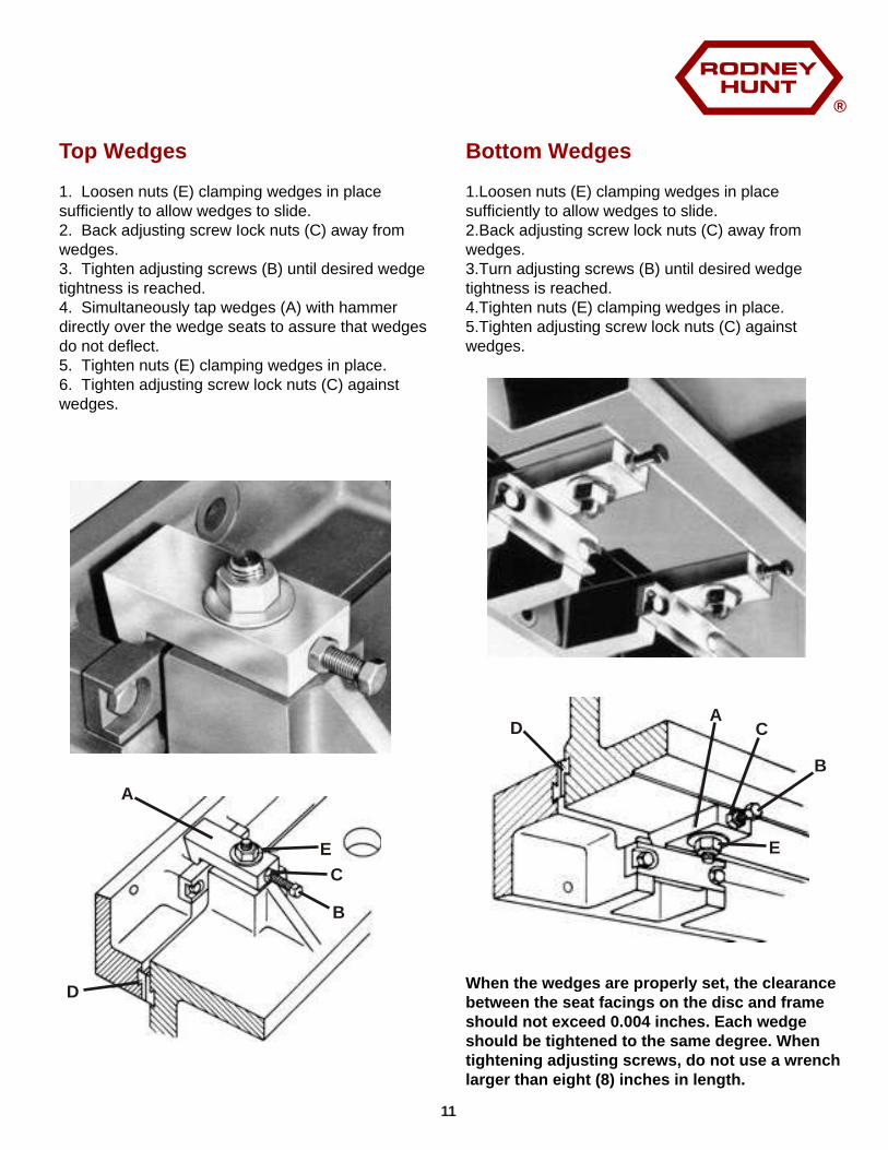
1. Loosen nuts (E) clamping wedges in place sufficiently to allow wedges to slide.2. Back adjusting screw Iock nuts (C) away from wedges.3. Tighten adjusting screws (B) until desired wedge tightness is reached.4. Simultaneously tap wedges (A) with hammer directly over the wedge seats to assure that wedges do not deflect.5. Tighten nuts (E) clamping wedges in place.6. Tighten adjusting screw lock nuts (C) against wedges.
Bottom Wedges
1.Loosen nuts (E) clamping wedges in place sufficiently to allow wedges to slide.2.Back adjusting screw lock nuts (C) away from wedges.3.Turn adjusting screws (B) until desired wedge tightness is reached.4.Tighten nuts (E) clamping wedges in place.5.Tighten adjusting screw lock nuts (C) against wedges.
When the wedges are properly set, the clearance between the seat facings on the disc and frame should not exceed 0.004 inches. Each wedge should be tightened to the same degree. When tightening adjusting screws, do not use a wrench larger than eight (8) inches in length.
A
B
C
D
E
A
B
CD
E
11
®
Slide Gates
Installation
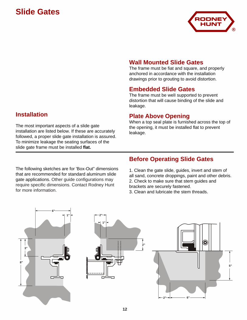
The most important aspects of a slide gate installation are listed below. If these are accurately followed, a proper slide gate installation is assured. To minimize leakage the seating surfaces of the slide gate frame must be installed flat.
The following sketches are for 'Box-Out” dimensions that are recommended for standard aluminum slide gate applications. Other guide configurations may require specific dimensions. Contact Rodney Hunt for more information.
Wall Mounted Slide Gates
Embedded Slide Gates
Plate Above Opening
Before Operating Slide Gates
The frame must be fiat and square, and properly anchored in accordance with the installation drawings prior to grouting to avoid distortion.
The frame must be welI supported to prevent distortion that will cause binding of the slide and leakage.
When a top seal plate is furnished across the top of the opening, it must be installed flat to prevent leakage.
1. Clean the gate slide, guides, invert and stem of all sand, concrete droppings, paint and other debris.2. Check to make sure that stem guides and brackets are securely fastened.3. Clean and lubricate the stem threads.
6”
1”
8”
3”
1”
2”
2”
5”
6”2”
12
®
Operating Mechanisms
Manually Operated Floor Stands
All floor stands and operating devices are identified by a tag showing the installation drawing number and should be used with the proper gate and stem.
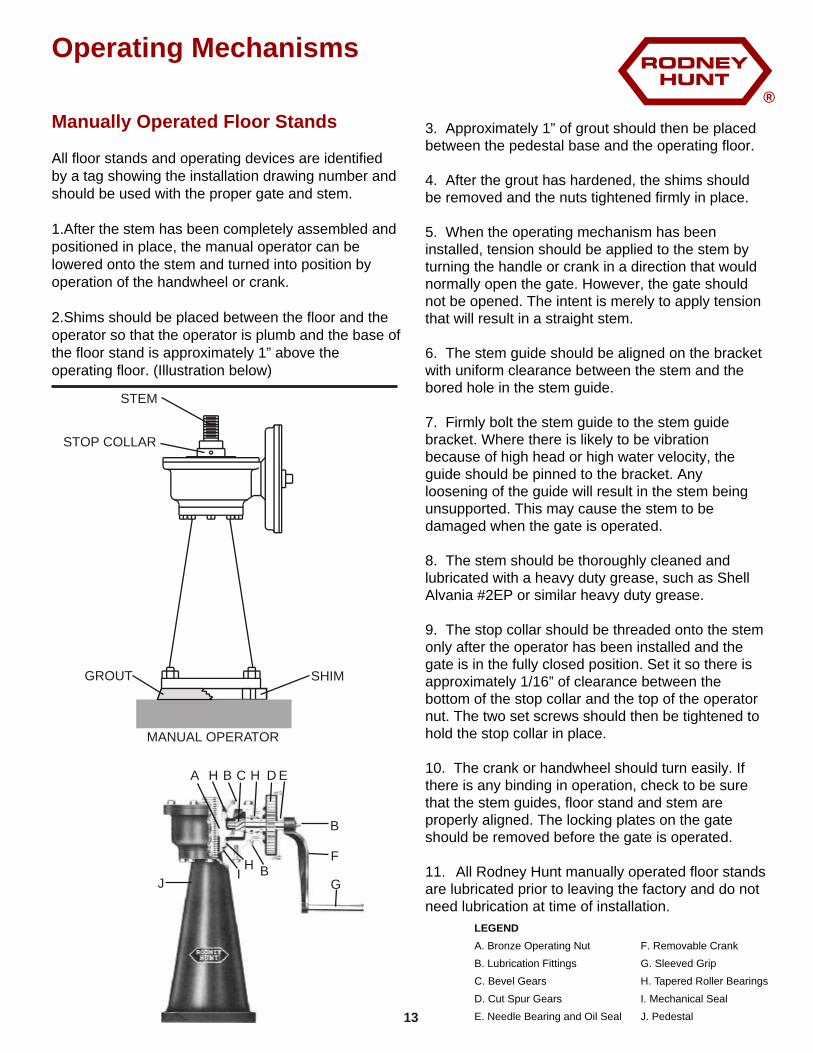
1.After the stem has been completely assembled and positioned in place, the manual operator can be lowered onto the stem and turned into position by operation of the handwheel or crank.
2.Shims should be placed between the floor and the operator so that the operator is plumb and the base of the floor stand is approximately 1” above the operating floor. (Illustration below)
3. Approximately 1” of grout should then be placed between the pedestal base and the operating floor.
4. After the grout has hardened, the shims should be removed and the nuts tightened firmly in place.
5. When the operating mechanism has been installed, tension should be applied to the stem by turning the handle or crank in a direction that would normally open the gate. However, the gate should not be opened. The intent is merely to apply tension that will result in a straight stem.
6. The stem guide should be aligned on the bracket with uniform clearance between the stem and the bored hole in the stem guide.
7. Firmly bolt the stem guide to the stem guide bracket. Where there is likely to be vibration because of high head or high water velocity, the guide should be pinned to the bracket. Any loosening of the guide will result in the stem being unsupported. This may cause the stem to be damaged when the gate is operated.
8. The stem should be thoroughly cleaned and lubricated with a heavy duty grease, such as Shell Alvania #2EP or similar heavy duty grease.
9. The stop collar should be threaded onto the stem only after the operator has been installed and the gate is in the fully closed position. Set it so there is approximately 1/16” of clearance between the bottom of the stop collar and the top of the operator nut. The two set screws should then be tightened to hold the stop collar in place.
10. The crank or handwheel should turn easily. If there is any binding in operation, check to be sure that the stem guides, floor stand and stem are properly aligned. The locking plates on the gate should be removed before the gate is operated.
11. All Rodney Hunt manually operated floor stands are lubricated prior to leaving the factory and do not need lubrication at time of installation.
STEM
STOP COLLAR
GROUT SHIM
MANUAL OPERATOR
LEGEND
A. Bronze Operating Nut
B. Lubrication Fittings
C. Bevel Gears
D. Cut Spur Gears
E. Needle Bearing and Oil Seal
F. Removable Crank
G. Sleeved Grip
H. Tapered Roller Bearings
I. Mechanical Seal
J. Pedestal
A B C D E
F
G
H
IJ
H
B
BH
13
®
Operating Mechanisms
Electric Motor Driven Floor Stands
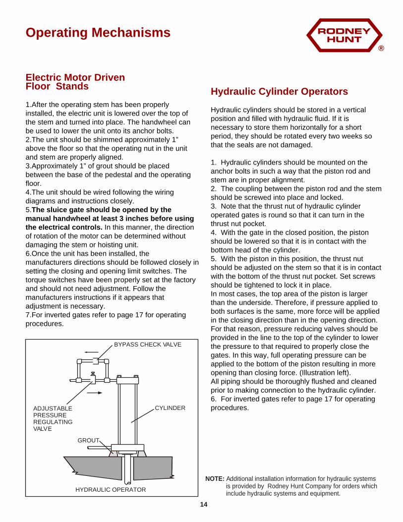
1.After the operating stem has been properly installed, the electric unit is lowered over the top of the stem and turned into place. The handwheel can be used to Iower the unit onto its anchor bolts.2.The unit should be shimmed approximately 1” above the floor so that the operating nut in the unit and stem are properly aligned.3.Approximately 1” of grout should be placed between the base of the pedestal and the operating floor.4.The unit should be wired following the wiring diagrams and instructions closely.5.The sluice gate should be opened by the manual handwheel at least 3 inches before using the electrical controls. In this manner, the direction of rotation of the motor can be determined without damaging the stem or hoisting unit.6.Once the unit has been installed, the manufacturers directions should be followed closely in setting the closing and opening limit switches. The torque switches have been properly set at the factory and should not need adjustment. Follow the manufacturers instructions if it appears that adjustment is necessary.7.For inverted gates refer to page 17 for operating procedures.
Hydraulic Cylinder Operators
Hydraulic cylinders should be stored in a vertical position and filled with hydraulic fluid. If it is necessary to store them horizontally for a short period, they should be rotated every two weeks so that the seals are not damaged.
1. Hydraulic cylinders should be mounted on the anchor bolts in such a way that the piston rod and stem are in proper alignment.2. The coupling between the piston rod and the stem should be screwed into place and locked.3. Note that the thrust nut of hydraulic cylinder operated gates is round so that it can turn in the thrust nut pocket.4. With the gate in the closed position, the piston should be lowered so that it is in contact with the bottom head of the cylinder.5. With the piston in this position, the thrust nut should be adjusted on the stem so that it is in contact with the bottom of the thrust nut pocket. Set screws should be tightened to lock it in place.In most cases, the top area of the piston is larger than the underside. Therefore, if pressure applied to both surfaces is the same, more force will be applied in the closing direction than in the opening direction. For that reason, pressure reducing valves should be provided in the line to the top of the cylinder to lower the pressure to that required to properly close the gates. In this way, full operating pressure can be applied to the bottom of the piston resulting in more opening than closing force. (Illustration left).All piping should be thoroughly flushed and cleaned prior to making connection to the hydraulic cylinder.6. For inverted gates refer to page 17 for operating procedures.
BYPASS CHECK VALVE
ADJUSTABLEPRESSUREREGULATINGVALVE
GROUT
CYLINDER
HYDRAULIC OPERATOR
NOTE: Additional installation information for hydraulic systems is provided by Rodney Hunt Company for orders which include hydraulic systems and equipment.
14
®
Pipe Covers
Galvanized Steel Pipe Cover
Clear Plastic Cover
Mechanical Dial Position Indicator
Galvanized steel pipe covers are furnished with brackets for bolting to the top of the crank operated floor stand. Care should be taken that the proper length of cover is placed on the correct gate. ln general, the cover should be approximately 6” longer than the height of the sluice gate. The cover will be identified at the time of shipment.
1.The clear butyrate cover is mounted on the manual hoist by aluminum brackets bolted to the top of the hoist. On electric driven hoists, the butyrate cover is threaded into the top of the hoist.2.Mylar tapes placed on clear covers for position indication should be properly located with the gate in the fully closed or open position. Mylar tape is self-sticking and easily applied. The surface of the plastic should be cleaned before application.
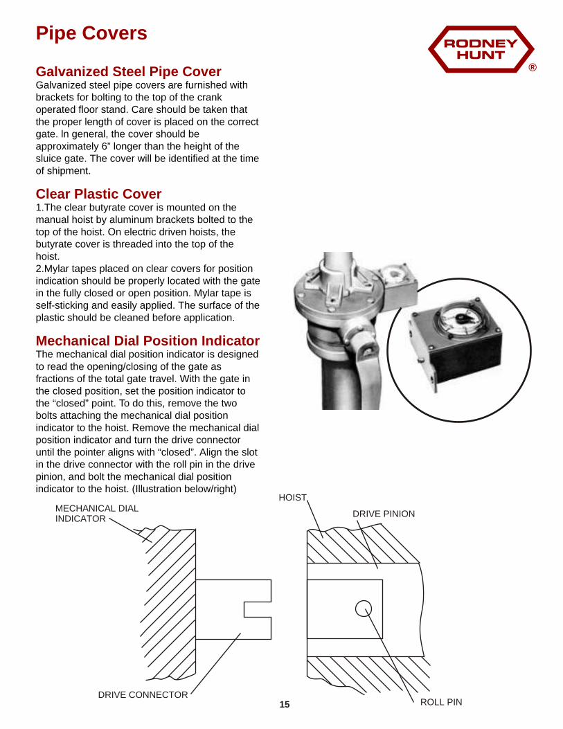
The mechanical dial position indicator is designed to read the opening/closing of the gate as fractions of the total gate travel. With the gate in the closed position, set the position indicator to the “closed” point. To do this, remove the two bolts attaching the mechanical dial position indicator to the hoist. Remove the mechanical dial position indicator and turn the drive connector until the pointer aligns with “closed”. Align the slot in the drive connector with the roll pin in the drive pinion, and bolt the mechanical dial position indicator to the hoist. (Illustration below/right)
DRIVE CONNECTOR
MECHANICAL DIALINDICATOR
ROLL PIN
HOIST
DRIVE PINION
15
®
Stems and Stem Guide
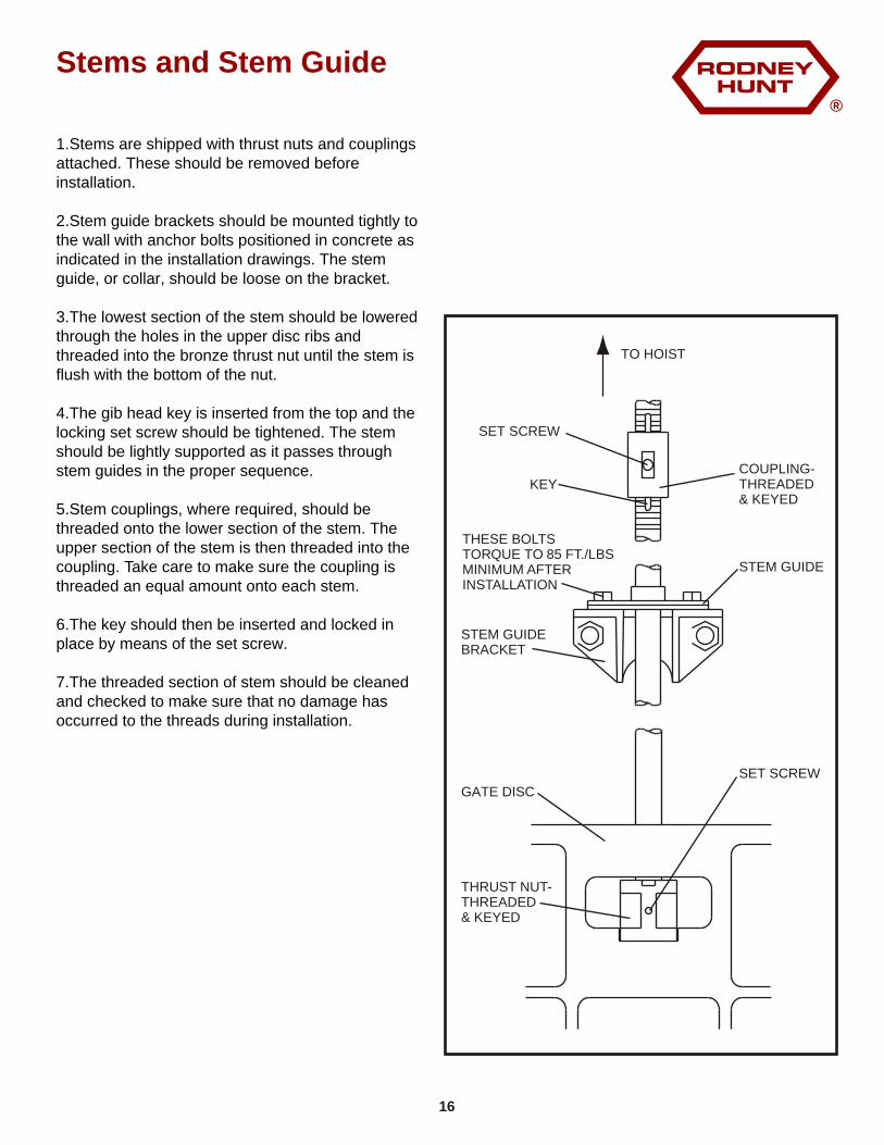
1.Stems are shipped with thrust nuts and couplings attached. These should be removed before installation.
2.Stem guide brackets should be mounted tightly to the wall with anchor bolts positioned in concrete as indicated in the installation drawings. The stem guide, or collar, should be loose on the bracket.
3.The lowest section of the stem should be lowered through the holes in the upper disc ribs and threaded into the bronze thrust nut until the stem is flush with the bottom of the nut.
4.The gib head key is inserted from the top and the locking set screw should be tightened. The stem should be lightly supported as it passes through stem guides in the proper sequence.
5.Stem couplings, where required, should be threaded onto the lower section of the stem. The upper section of the stem is then threaded into the coupling. Take care to make sure the coupling is threaded an equal amount onto each stem.
6.The key should then be inserted and locked in place by means of the set screw.
7.The threaded section of stem should be cleaned and checked to make sure that no damage has occurred to the threads during installation.
SET SCREW
COUPLING-THREADED & KEYED
KEY
THESE BOLTSTORQUE TO 85 FT./LBSMINIMUM AFTERINSTALLATION
STEM GUIDE
STEM GUIDEBRACKET
GATE DISC
THRUST NUT-THREADED& KEYED
TO HOIST
16
SET SCREW
®
Operating Instructions -
Sluice Gates
Inverted SIuice GatesWARNING -
Before Operating Sluice Gate
Initial Operation - Sluice Gates
Locking plates for inverted sluice gates should not be removed until the operating mechanism is securely attached to the gate disc.
For electric and manual operators, a stop collar should be attached to the top of the stem to prevent accidentally running the stem through the operating nut and dropping the disc. For Hydraulic Cylinder operators, the disc should be supported externally until the cylinder and all connecting lines have been filled with pressurized fluid and then only when the directional valves are in the neutral or up positions. Note that filling the cylinder with fluid while the piston is fully retracted can result in a trapped air pocket which could allow the disc to drop a few inches after removal of the locking plates.
1. MAKE SURE THAT ALL LOCKING PLATES HAVE BEEN REMOVED.2. CLEAN THE TOP 0F THE GATE OF ALL SAND, CONCRETE DROPPINGS AND OTHER DEBRIS.3. CHECK TO MAKE SURE THAT STEM GUIDES AND BRACKETS ARE SECURELY FASTENED.4. CLEAN AND LUBRICATE THE STEM.
1. Before using the sluice gates, seat facings should be thoroughly cleaned. Paint which may have been deposited on the seat facing should be removed. Seats and wedges should be coated with a light grease.2. Operating stems should be thoroughly cleaned and greased with a high grade, heavy duty lubricant such as:
Mobil- Mobilith Aw2 (EP2)
3. The gate should be operated to the fully open and fully closed positions slowly, and carefully, to check for misalignment or problems in operation.
Manual Operators1. Manual operators are lubricated at the factory before initial operation and do not require additional lubrication.2. If operation becomes difficult, check stem lubrication.Excess force should not be applied to the crank.
The Instruction Manual furnished with electric motor driven floor stands should be read carefully before the unit is installed and operated. The gate must be manually opened about 3” before initial electric operation is attempted. Check motor rotation by activating the “close” circuit making certain the gate travels in the “close” direction. Revise motor leads to obtain proper rotation if necessary.
The gate should not be operated electrically through its full travel until both “close” and “open” geared limit switches have been properly set. Adjust the “open” switch so that the opening cycle does not allow the end of the thread of the operating stem to enter the floor stand nut. Geared limit switches cannot be factory set and must be set by the contractor at the job site. Follow all safety precautions for electric operators.
The Instruction Manual furnished with the hydraulic equipment should be read carefully before the units are installed and operated.Hydraulic systems vary considerably in terms of operating characteristics and in the types of equipment available. Specific operating modes, start-up instructions, and safety precautions must be understood prior to initial operation. All hydraulic systems use a pressurized fluid and should be operated with care.
The Rodney Hunt Co. can provide a representative for start-up assistance on those systems supplied by us. See our field service policy on the last page.
Electric Operators
Hydraulic Operators
17
®
Operating Instructions -
Slide Gates
Rodney Hunt fabricated slide gates are constructed to operate satisfactorily under the specified operating conditions. These gates should be operated with care so as not to exceed the specified conditions. If, in the operation of the gate, an obstruction is met, either in the opening or closing direction, the obstruction should be removed before continuing in the operation. When the gate is fully opened or closed, excessive force should not be placed on the gate or gate stem by the operator in an effort to move the gate further.If a problem arises in the operation of the gate, such as an unusual head condition or evidence of excessive corrosion, the factory should be consulted before the gate is used or operated.
1. Check hoist, stem guide, and gate attaching bolts for proper tightness.2. Apply tension to stem and check any stem guides for proper alignment. There must be a uniform clearance between the operating stem and all stem guides.3. Check gate guide groove and clean off any foreign matter.4. With gate in fully opened position, check seating surfaces of slide and frame for paint, concrete or other foreign matter. Also check the threaded portion of the stem. It must be clean and lubricated with a heavy duty grease such as:
Mobil- Mobilith Aw2 (Ep2)
5. If J-seals are supplied, clean contact surfaces on disc and adjust seal.6. Check the invert of flush bottom gates for concrete splatter or other debris.7. Adjust stem stop collar to within 1/16” of the top of the hoist operating nut and lock in place.8. Install stem cover if furnished.
Installation Inspection Check List
Manually Operated Slide Gates
18
®
Sluice Gates -
Trouble Shooting Tips
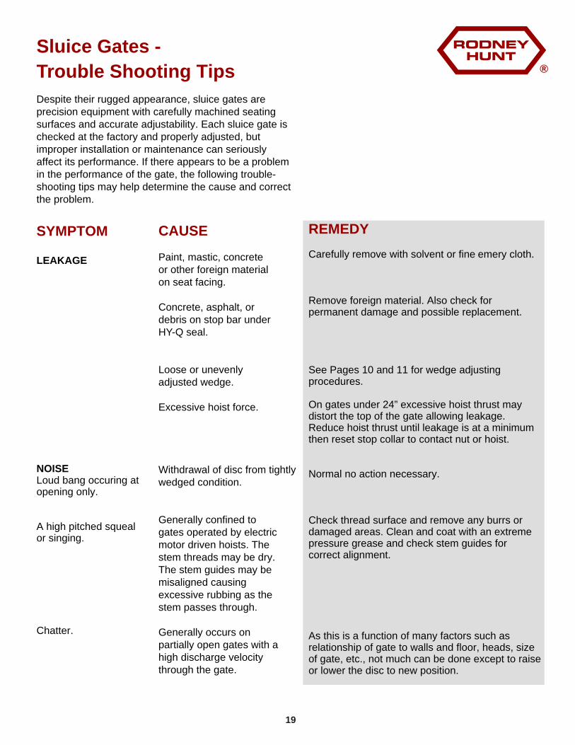
Despite their rugged appearance, sluice gates are precision equipment with carefully machined seating surfaces and accurate adjustability. Each sluice gate is checked at the factory and properly adjusted, but improper installation or maintenance can seriously affect its performance. If there appears to be a problem in the performance of the gate, the following trouble-shooting tips may help determine the cause and correct the problem.
REMEDY
Carefully remove with solvent or fine emery cloth.
Remove foreign material. Also check for permanent damage and possible replacement.
See Pages 10 and 11 for wedge adjusting procedures.
On gates under 24” excessive hoist thrust may distort the top of the gate allowing leakage. Reduce hoist thrust until leakage is at a minimum then reset stop collar to contact nut or hoist.
Normal no action necessary.
Check thread surface and remove any burrs or damaged areas. Clean and coat with an extreme pressure grease and check stem guides for correct alignment.
As this is a function of many factors such as relationship of gate to walls and floor, heads, size of gate, etc., not much can be done except to raise or lower the disc to new position.
SYMPTOM
LEAKAGE
NOISELoud bang occuring at opening only.
A high pitched squeal or singing.
Chatter.
CAUSE
Paint, mastic, concrete or other foreign material on seat facing.
Concrete, asphalt, or debris on stop bar under HY-Q seal.
Loose or unevenly adjusted wedge.
Excessive hoist force.
Withdrawal of disc from tightly wedged condition.
Generally confined to gates operated by electric motor driven hoists. The stem threads may be dry. The stem guides may be misaligned causing excessive rubbing as the stem passes through.
Generally occurs on partially open gates with a high discharge velocity through the gate.
19
®
Sluice Gates -
Trouble Shooting Tips (cont’d)
REMEDY
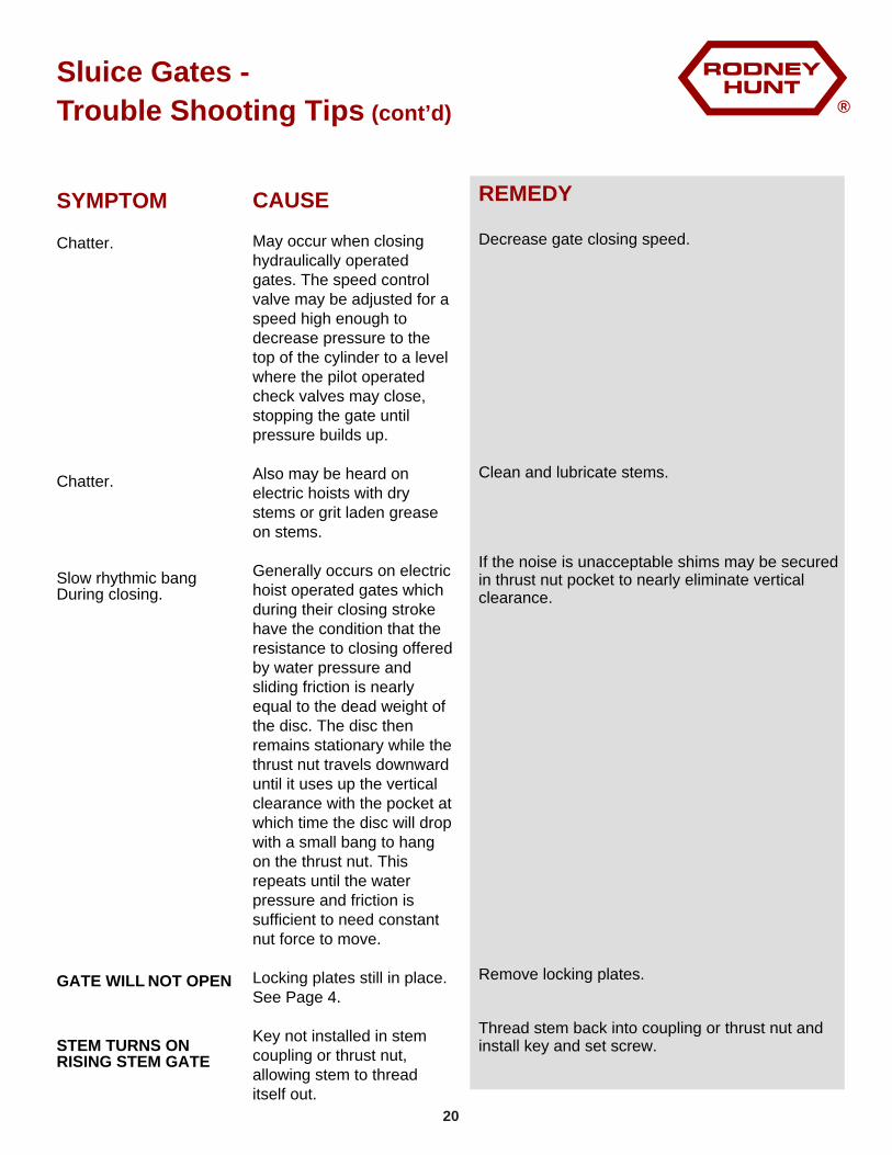
Decrease gate closing speed.
Clean and lubricate stems.
If the noise is unacceptable shims may be secured in thrust nut pocket to nearly eliminate vertical clearance.
Remove locking plates.
Thread stem back into coupling or thrust nut and install key and set screw.
SYMPTOM
Chatter.
Chatter.
Slow rhythmic bang During closing.
GATE WILL NOT OPEN
STEM TURNS ONRISING STEM GATE
CAUSE
May occur when closing hydraulically operated gates. The speed control valve may be adjusted for a speed high enough to decrease pressure to the top of the cylinder to a level where the pilot operated check valves may close, stopping the gate until pressure builds up.
Also may be heard on electric hoists with dry stems or grit laden grease on stems.
Generally occurs on electric hoist operated gates which during their closing stroke have the condition that the resistance to closing offered by water pressure and sliding friction is nearly equal to the dead weight of the disc. The disc then remains stationary while the thrust nut travels downward until it uses up the vertical clearance with the pocket at which time the disc will drop with a small bang to hang on the thrust nut. This repeats until the water pressure and friction is sufficient to need constant nut force to move.
Locking plates still in place. See Page 4.
Key not installed in stem coupling or thrust nut, allowing stem to thread itself out.
20
®
Sluice Gates -
Trouble Shooting Tips (cont’d)
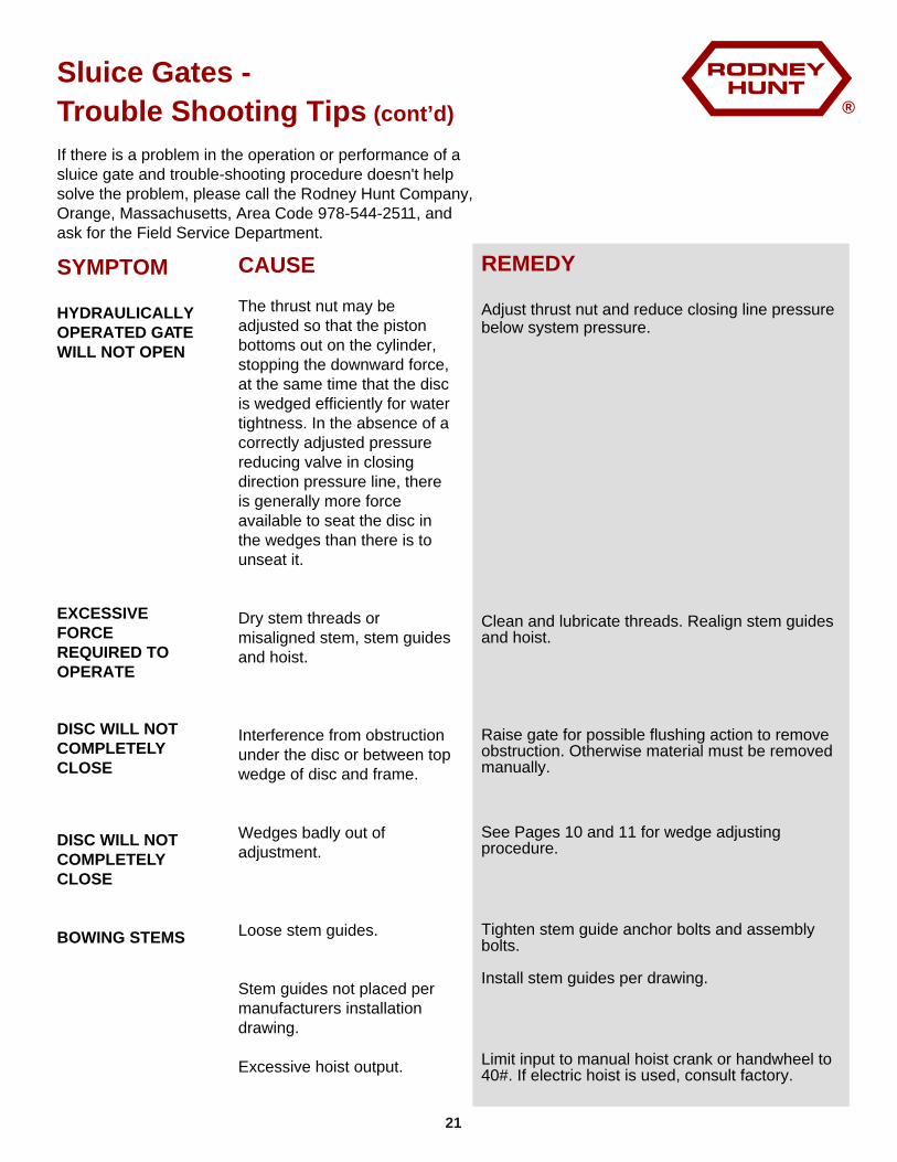
If there is a problem in the operation or performance of a sluice gate and trouble-shooting procedure doesn't help solve the problem, please call the Rodney Hunt Company, Orange, Massachusetts, Area Code 978-544-2511, and ask for the Field Service Department.
REMEDY
Adjust thrust nut and reduce closing line pressure below system pressure.
Clean and lubricate threads. Realign stem guides and hoist.
Raise gate for possible flushing action to remove obstruction. Otherwise material must be removed manually.
See Pages 10 and 11 for wedge adjusting procedure.
Tighten stem guide anchor bolts and assembly bolts.
Install stem guides per drawing.
Limit input to manual hoist crank or handwheel to 40#. If electric hoist is used, consult factory.
SYMPTOM
HYDRAULICALLYOPERATED GATEWILL NOT OPEN
EXCESSIVEFORCEREQUIRED TOOPERATE
DISC WILL NOTCOMPLETELYCLOSE
DISC WILL NOTCOMPLETELYCLOSE
BOWING STEMS
CAUSE
The thrust nut may be adjusted so that the piston bottoms out on the cylinder, stopping the downward force, at the same time that the disc is wedged efficiently for water tightness. In the absence of a correctly adjusted pressure reducing valve in closing direction pressure line, there is generally more force available to seat the disc in the wedges than there is to unseat it.
Dry stem threads or misaligned stem, stem guides and hoist.
Interference from obstruction under the disc or between top wedge of disc and frame.
Wedges badly out of adjustment.
Loose stem guides.
Stem guides not placed per manufacturers installation drawing.
Excessive hoist output.
21
®
Slide Gates -
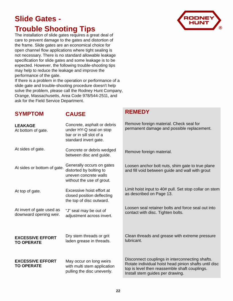
Trouble Shooting Tips The installation of slide gates requires a great deal of care to prevent damage to the gates and distortion of the frame. Slide gates are an economical choice for open channel flow applications where tight sealing is not necessary. There is no standard allowable leakage specification for slide gates and some leakage is to be expected. However, the following trouble-shooting tips may help to reduce the leakage and improve the performance of the gate.If there is a problem in the operation or performance of a slide gate and trouble-shooting procedure doesn't help solve the problem, please call the Rodney Hunt Company, Orange, Massachusetts, Area Code 978/544-2511, and ask for the Field Service Department.
REMEDY
Remove foreign material. Check seal for permanent damage and possible replacement.
Remove foreign material.
Loosen anchor bolt nuts, shim gate to true plane and fill void between guide and wall with grout
Limit hoist input to 40# pull. Set stop collar on stem as described on Page 13.
Loosen seal retainer bolts and force seal out into contact with disc. Tighten bolts.
Clean threads and grease with extreme pressure lubricant.
Disconnect couplings in interconnecting shafts. Rotate individual hoist head pinion shafts until disc top is level then reassemble shaft couplings.Install stem guides per drawing.
SYMPTOM
LEAKAGEAt bottom of gate.
At sides of gate.
At sides or bottom of gate.
At top of gate.
At invert of gate used as downward opening weir.
EXCESSIVE EFFORT TO OPERATE
EXCESSIVE EFFORT TO OPERATE
CAUSE
Concrete, asphalt or debris under HY-Q seal on stop bar or in sill slot of a standard invert gate.
Concrete or debris wedged between disc and guide.
Generally occurs on gates distorted by bolting to uneven concrete walls without the use of grout.
Excessive hoist effort at closed position deflecting the top of disc outward.
“J” seal may be out of adjustment across invert.
Dry stem threads or grit laden grease in threads.
May occur on long weirs with multi stem application pulling the disc unevenly.
22
®
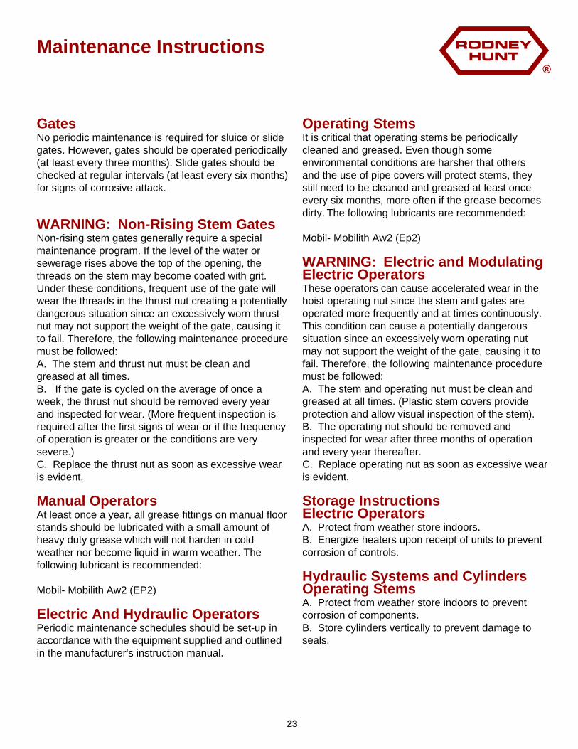
Maintenance Instructions
Gates
WARNING: Non-Rising Stem Gates
Manual Operators
Electric And Hydraulic Operators
No periodic maintenance is required for sluice or slide gates. However, gates should be operated periodically (at Ieast every three months). Slide gates should be checked at regular intervals (at least every six months) for signs of corrosive attack.
Non-rising stem gates generally require a special maintenance program. If the level of the water or sewerage rises above the top of the opening, the threads on the stem may become coated with grit. Under these conditions, frequent use of the gate will wear the threads in the thrust nut creating a potentially dangerous situation since an excessively worn thrust nut may not support the weight of the gate, causing it to fail. Therefore, the following maintenance procedure must be followed:A. The stem and thrust nut must be clean and greased at all times.B. If the gate is cycled on the average of once a week, the thrust nut should be removed every year and inspected for wear. (More frequent inspection is required after the first signs of wear or if the frequency of operation is greater or the conditions are very severe.)C. Replace the thrust nut as soon as excessive wear is evident.
At least once a year, all grease fittings on manual floor stands should be lubricated with a small amount of heavy duty grease which will not harden in cold weather nor become liquid in warm weather. The following lubricant is recommended:
Mobil- Mobilith Aw2 (EP2)
Periodic maintenance schedules should be set-up in accordance with the equipment supplied and outlined in the manufacturer's instruction manual.
Operating Stems
WARNING: Electric and Modulating Electric Operators
Storage InstructionsElectric Operators
Hydraulic Systems and CylindersOperating Stems
It is critical that operating stems be periodically cleaned and greased. Even though some environmental conditions are harsher that others and the use of pipe covers will protect stems, they still need to be cleaned and greased at least once every six months, more often if the grease becomes dirty. The following lubricants are recommended:
Mobil- Mobilith Aw2 (Ep2)
These operators can cause accelerated wear in the hoist operating nut since the stem and gates are operated more frequently and at times continuously. This condition can cause a potentially dangerous situation since an excessively worn operating nut may not support the weight of the gate, causing it to fail. Therefore, the following maintenance procedure must be followed:A. The stem and operating nut must be clean and greased at all times. (Plastic stem covers provide protection and allow visual inspection of the stem).B. The operating nut should be removed and inspected for wear after three months of operation and every year thereafter.C. Replace operating nut as soon as excessive wear is evident.
A. Protect from weather store indoors.B. Energize heaters upon receipt of units to prevent corrosion of controls.
A. Protect from weather store indoors to prevent corrosion of components.B. Store cylinders vertically to prevent damage to seals.
23
®
Cleaning and Painting
Engineering Drawings
Some specifications require that sluice gates be cleaned and painted in the field.
1. The gate should not be disassembled unless absolutely necessary. The disc can be removed from the guides for separate handling by removing the locking plates.
2. Before sandblasting, all bronze surfaces should be properly protected. The wedges should not be removed from the gate.
3. After cleaning and painting, all masking should be removed and the bronze machined surfaces thoroughly cleaned. If the slides have been removed, they should be inserted into the proper frame. Locking plates should then be bolted in place.
The engineering drawings submitted by Rodney Hunt Co. for approval and/or field use, are planned so that the installation drawing is the master reference.
This drawing depicts as much as possible of the structure surrounding the Rodney Hunt Co. supplied equipment. The location of embedded material such as anchor bolts and wall thimbles are described. The identification of fasteners and components (studs, anchor bolts, gate assemblies, hoists, stems, stem guides, stem couplings, torque plates, wall thimbles, thrust nuts, stop collars and other equipment) is done by calling out physical sizes and/or assembly or detail drawing numbers. More information is available on those detail or assembly drawings which have been included with the installation drawing.
In many cases tabulated drawings are used which describe variables for a given piece of equipment. The applicable variation is identified by the drawing number suffix as shown on the installation drawing.
The Rodney Hunt Company does not recommend the stocking of spare parts by customers or owners since the equipment is designed for a very long service life when recommended maintenance procedures are followed.
Spare Parts
If a repair part is required, contact the FIELD SERVICE DEPARTMENT at the factory with the following information:
1. Original shop order number which is indicated on correspondence and installation drawings and stamped on the end of operating stem.
2. The installation drawing number, and a description of the part, with any other available drawing numbers.
3. Description of damage and cause.
4. Approximate delivery requirements.
This information will help Rodney Hunt to better serve you.
Write or call the Rodney Hunt Company if you encounter any installation or adjustment problems not covered in this manual.
Any Questions?
24
®
FieId Service Policy
Shortages
Damage In Transit
Installation, Inspectionand Adjustment
Field Trouble
The equipment furnished on this order has been adjusted and inspected prior to leaving the factory and has been accepted by the transporting company. Please check the packing list accompanying the shipment for shortages and examine the equipment for damages prior to accepting the shipment. Before storing or installing this equipment, read the installation manual that accompanies the shipment.
If a shortage exists, notify the Rodney Hunt Company, Customer Service Department, immediately upon receipt of the equipment. Claims for shortages of equipment shown on the packing list will not be accepted unless filed within thirty days after shipment of the equipment.
If the equipment has been damaged in transit, the purchaser is responsible for filing the claim with the transportation company. Contact the Rodney Hunt Shipping Department for assistance in filing the claim.
Installation supervision, inspection of installed equipment, adjustment of the wedges, setting of limit switches and certification of satisfactory initial operation are not included unless specifically indicated on the customer’s purchase order and accepted by the company. The company wiIl provide this service at the charges listed from the Rodney Hunt Customer Service Department.
When trouble develops either in the installation, operation or performance of the equipment, the installation manual and drawings should be checked to determine if the equipment has been installed properly. If proper performance or operation cannot be obtained and assistance from the factory is desired, please contact the company. Arrangements will be made to send a man to the job site if this is required. This man will make a thorough examination of the problem and if the equipment is faulty in workmanship or material, the necessary repairs or adjustments will be made by the factory at no cost to the purchaser.
If, however, the problem is due to faulty installation or adjustment, the cost of the field service will be charged to the purchaser.
If repairs are made in the field by the purchaser or authorized by the purchaser, backcharges for these repairs will not be accepted by the company unless the company has been notified prior to the incurring of these costs and has accepted the responsibility for these repairs.
The company will not be liable for contingent costs or costs of delays due to the faulty equipment and the repairs thereof.
Field service charges begin from the time of departure until the return of the service man and include a daily rate plus travel and subsistence expenses. Premium day and hourly rates will be charged on Saturdays, Sundays and Holidays and for time spent before 6 a.m. or after 5 p.m., or over eight hours per day. A schedule of Field Service charges is available from the Rodney Hunt Customer Service Department.
The minimum order value for replacement parts is$50.00.
For a period of one year from the date of delivery of the equipment, the company guarantees that the materials and equipment shall be free from defects of material and workmanship and agrees to replace any part or parts breaking within such one year providing the purchaser gives a written notice of such breakage and that such breakage, in the opinion of the company, shows unmistakable evidence of defective material or workmanship. The liability of the company shall not in any case exceed the cost of repairing or replacing the defective parts and in no event shall the company be liable for loss of income or other expenses or consequential damage. At the end of said one year all liability of the company shall cease and terminate.
Field Service Charges
The Rodney Hunt Guarantee
25


![Guardacabos - NUESTROS PRODUCTOScablespire.com/archivos/enlaces_1390243253.pdf · [8] Guardacabos THIMBLES /COSSES Guardacabos corazón THIMBLES COSSECOEUR Guardacabos fuerte fundido](https://img.pdfslide.net/doc/110x75/5bd4a63e09d3f204338c79dd/guardacabos-nuestros-8-guardacabos-thimbles-cosses-guardacabos-corazon.jpg)