Embed Size (px)
Citation preview
INSTRUCTION MANUAL
DIGITAL POWER METER
KEW 6305
Kyoritsu Electrical Instruments Works, Ltd.
1 KEW6305
Unpacking procedure
We thank you for purchasing our digital Power Meter KEW6305. Please check the contents and instrument before use.
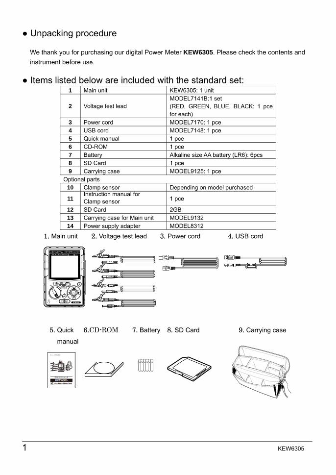
Items listed below are included with the standard set: 1 Main unit KEW6305: 1 unit
2 Voltage test lead MODEL7141B:1 set (RED, GREEN, BLUE, BLACK: 1 pce for each)
3 Power cord MODEL7170: 1 pce 4 USB cord MODEL7148: 1 pce 5 Quick manual 1 pce 6 CD-ROM 1 pce 7 Battery Alkaline size AA battery (LR6): 6pcs 8 SD Card 1 pce 9 Carrying case MODEL9125: 1 pce
Optional parts 10 Clamp sensor Depending on model purchased
11 Instruction manual for Clamp sensor 1 pce
12 SD Card 2GB 13 Carrying case for Main unit MODEL9132 14 Power supply adapter MODEL8312
1. Main unit 2. Voltage test lead 3. Power cord 4. USB cord
5. Quick 6.CD-ROM 7. Battery 8. SD Card 9. Carrying case
manual
KEW6305 2
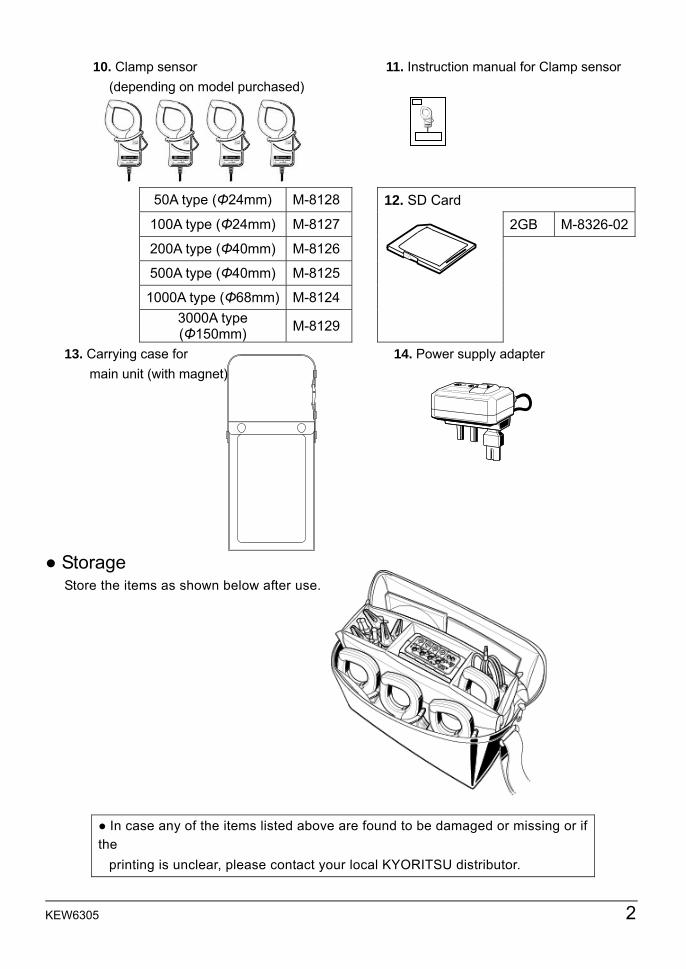
10. Clamp sensor 11. Instruction manual for Clamp sensor (depending on model purchased)
50A type (Φ24mm) M-8128 12. SD Card
100A type (Φ24mm) M-8127 2GB M-8326-02
200A type (Φ40mm) M-8126
500A type (Φ40mm) M-8125
1000A type (Φ68mm) M-8124 3000A type (Φ150mm) M-8129
13. Carrying case for 14. Power supply adapter main unit (with magnet)
Storage
Store the items as shown below after use.
In case any of the items listed above are found to be damaged or missing or if the printing is unclear, please contact your local KYORITSU distributor.
3 KEW6305
Safety warnings
This instrument has been designed, manufactured and tested according to IEC 61010-1: Safety requirements for Electronic Measuring apparatus, and delivered in the best condition after passing quality control tests. This instruction manual contains warnings and safety procedures which have to be observed by the user to ensure safe operation of the instrument and to maintain it in safe condition. Therefore, read through these operating instructions before using the
instrument.
WARNING - For about Instruction manual - Read through and understand the instructions contained in this manual before using the instrument. Keep the manual at hand to enable quick reference whenever necessary. The instrument is to be used only in its intended applications. Understand and follow all the safety instructions contained in the manual. Read the enclosed Quick manual after reading this instruction manual. As to the Clamp sensor use, refer to the instruction manual supplied with the sensor. It is essential that the above instructions are adhered to. Failure to follow the above instructions may cause injury, instrument damage and/or damage to equipment under test.
The symbol indicated on the instrument, means that the user must refer to the related parts in the manual for safe operation of the instrument. It is essential to read the instructions wherever the
symbol appears in the manual.
DANGER : is reserved for conditions and actions that are likely to cause serious or fatal injury.
WARNING : is reserved for conditions and actions that can cause serious or fatal injury.
CAUTION : is reserved for conditions and actions that can cause injury or instrument damage.
KEW6305 4
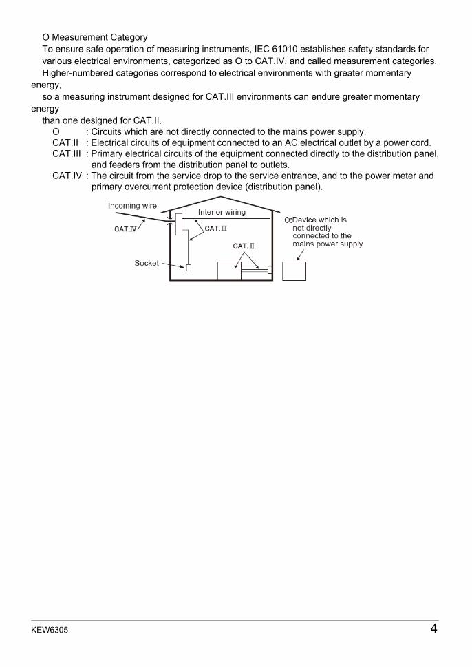
O Measurement Category To ensure safe operation of measuring instruments, IEC 61010 establishes safety standards for various electrical environments, categorized as O to CAT.IV, and called measurement categories. Higher-numbered categories correspond to electrical environments with greater momentary
energy, so a measuring instrument designed for CAT.III environments can endure greater momentary
energy than one designed for CAT.II.
O : Circuits which are not directly connected to the mains power supply. CAT.II : Electrical circuits of equipment connected to an AC electrical outlet by a power cord. CAT.III : Primary electrical circuits of the equipment connected directly to the distribution panel, and feeders from the distribution panel to outlets. CAT.IV : The circuit from the service drop to the service entrance, and to the power meter and primary overcurrent protection device (distribution panel).
5 KEW6305
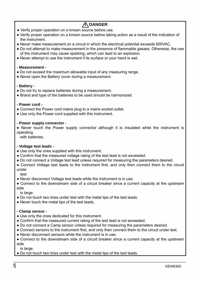
DANGER
Verify proper operation on a known source before use. Verify proper operation on a known source before taking action as a result of the indication of the instrument. Never make measurement on a circuit in which the electrical potential exceeds 600VAC. Do not attempt to make measurement in the presence of flammable gasses. Otherwise, the use of the instrument may cause sparking, which can lead to an explosion. Never attempt to use the instrument if its surface or your hand is wet. - Measurement - Do not exceed the maximum allowable input of any measuring range. Never open the Battery cover during a measurement. - Battery - Do not try to replace batteries during a measurement. Brand and type of the batteries to be used should be harmonized. - Power cord - Connect the Power cord mains plug to a mains socket outlet. Use only the Power cord supplied with this instrument. - Power supply connector - Never touch the Power supply connector although it is insulated while the instrument is operating with batteries. - Voltage test leads - Use only the ones supplied with this instrument. Confirm that the measured voltage rating of the test lead is not exceeded. Do not connect a Voltage test lead unless required for measuring the parameters desired. Connect Voltage test leads to the instrument first, and only then connect them to the circuit under test. Never disconnect Voltage test leads while the instrument is in use. Connect to the downstream side of a circuit breaker since a current capacity at the upstream side is large. Do not touch two lines under test with the metal tips of the test leads. Never touch the metal tips of the test leads. - Clamp sensor - Use only the ones dedicated for this instrument. Confirm that the measured current rating of the test lead is not exceeded. Do not connect a Camp sensor unless required for measuring the parameters desired. Connect sensors to the instrument first, and only then connect them to the circuit under test. Never disconnect sensors while the instrument is in use. Connect to the downstream side of a circuit breaker since a current capacity at the upstream side is large. Do not touch two lines under test with the metal tips of the test leads.
KEW6305 6
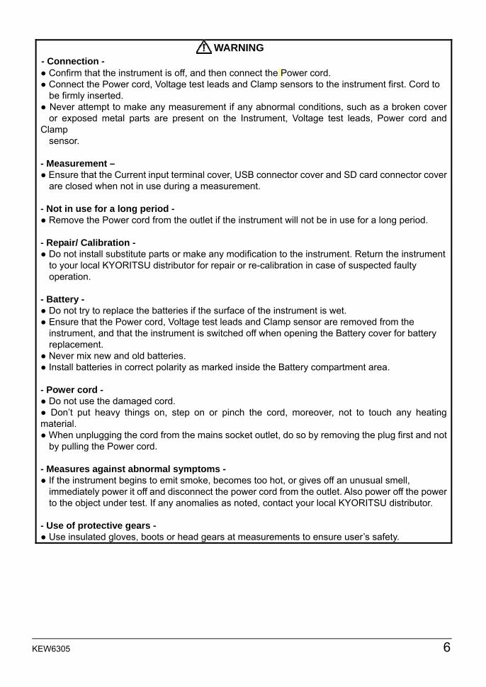
WARNING
- Connection - Confirm that the instrument is off, and then connect the Power cord. Connect the Power cord, Voltage test leads and Clamp sensors to the instrument first. Cord to be firmly inserted. Never attempt to make any measurement if any abnormal conditions, such as a broken cover or exposed metal parts are present on the Instrument, Voltage test leads, Power cord and Clamp sensor. - Measurement – Ensure that the Current input terminal cover, USB connector cover and SD card connector cover are closed when not in use during a measurement. - Not in use for a long period - Remove the Power cord from the outlet if the instrument will not be in use for a long period. - Repair/ Calibration - Do not install substitute parts or make any modification to the instrument. Return the instrument to your local KYORITSU distributor for repair or re-calibration in case of suspected faulty operation. - Battery - Do not try to replace the batteries if the surface of the instrument is wet. Ensure that the Power cord, Voltage test leads and Clamp sensor are removed from the instrument, and that the instrument is switched off when opening the Battery cover for battery replacement. Never mix new and old batteries. Install batteries in correct polarity as marked inside the Battery compartment area. - Power cord - Do not use the damaged cord. Don’t put heavy things on, step on or pinch the cord, moreover, not to touch any heating material. When unplugging the cord from the mains socket outlet, do so by removing the plug first and not by pulling the Power cord. - Measures against abnormal symptoms - If the instrument begins to emit smoke, becomes too hot, or gives off an unusual smell, immediately power it off and disconnect the power cord from the outlet. Also power off the power to the object under test. If any anomalies as noted, contact your local KYORITSU distributor. - Use of protective gears - Use insulated gloves, boots or head gears at measurements to ensure user’s safety.
7 KEW6305
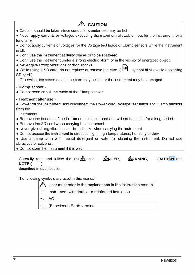
CAUTION
Caution should be taken since conductors under test may be hot. Never apply currents or voltages exceeding the maximum allowable input for the instrument for a long time. Do not apply currents or voltages for the Voltage test leads or Clamp sensors while the instrument is off. Don’t use the instrument at dusty places or to be spattered. Don’t use the instrument under a strong electric storm or in the vicinity of energized object. Never give strong vibrations or drop shocks. While using a SD card, do not replace or remove the card. ( symbol blinks while accessing SD card.) Otherwise, the saved data in the card may be lost or the instrument may be damaged. - Clamp sensor - Do not bend or pull the cable of the Clamp sensor. - Treatment after use - Power off the instrument and disconnect the Power cord, Voltage test leads and Clamp sensors from the instrument. Remove the batteries if the instrument is to be stored and will not be in use for a long period. Remove the SD card when carrying the instrument. Never give strong vibrations or drop shocks when carrying the instrument. Do not expose the instrument to direct sunlight, high temperatures, humidity or dew. Use a damp cloth with neutral detergent or water for cleaning the instrument. Do not use abrasives or solvents. Do not store the instrument if it is wet. Carefully read and follow the instructions: DANGER, WARNING, CAUTION and NOTE ( ) described in each section.
The following symbols are used in this manual:
User must refer to the explanations in the instruction manual. Instrument with double or reinforced insulation
AC (Functional) Earth terminal
~

KEW6305 8
1.1 KEW6305
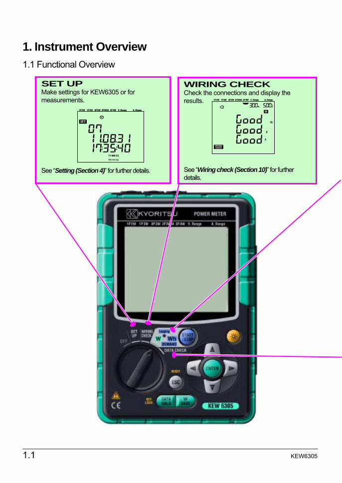
1. Instrument Overview 1.1 Functional Overview
SET UP Make settings for KEW6305 or for measurements. See “Setting (Section 4)” for further details.
WIRING CHECK Check the connections and display the results. See “Wiring check (Section 10)” for further details.
KEW6305 1.2
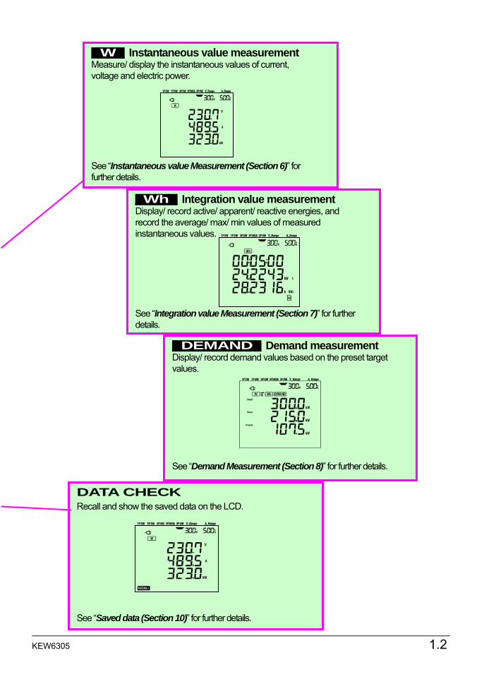
_W_ Instantaneous value measurementMeasure/ display the instantaneous values of current, voltage and electric power. See “Instantaneous value Measurement (Section 6)” for further details.
_Wh_ Integration value measurementDisplay/ record active/ apparent/ reactive energies, and record the average/ max/ min values of measured instantaneous values. See “Integration value Measurement (Section 7)” for further details.
_DEMAND_ Demand measurement Display/ record demand values based on the preset target values. See “Demand Measurement (Section 8)” for further details.
DATA CHECK Recall and show the saved data on the LCD. See “Saved data (Section 10)” for further details.
1.3 KEW6305
1.2 Features
This is a digital Power Clamp Meter that can be used for various wiring systems. Measured data can be saved either in the internal memory or SD card, and can be transmitted to PC via USB connection or by using SD card reader. Safety Construction Designed to meet the international safety standard IEC 61010-1 CAT.III 600V. Wiring configuration KEW6305 supports: Single-phase 2-wire, Single-phase 3-wire, Three-phase 3-wire, Three-phase 4-wire. Measurement and calculation KEW6305 measures voltage (RMS), current (RMS), active power, frequency and calculates reactive/ apparent power, power factor, neutral current and active/ reactive/ apparent energy. Demand measurement Electricity consumption can be easily monitored so as not to exceed the target maximum demand values. Saving data KEW6305 is endowed with a logging function with a preset recording interval. Data can be saved by manual operation or at pre-set time & date. Dual power supply system KEW6305 operates either with an AC power supply or with batteries. Both dry-cell batteries (alkaline) and rechargeable batteries (Ni-MH) can be used. In the event of an interruption, while operating with an AC power supply, power to the instrument is automatically restored by the batteries in the instrument. Large display Up to 3 measured items can be displayed on the large screen simultaneously. Light & compact design Clamp sensor type, compact and light weight design Application Data in the internal memory and in SD card can be transmitted to PC using USB connection or SD slot. The supplied PC software application enables easy settings of the instrument and analysis of the saved data from PC.
KEW6305 1.4
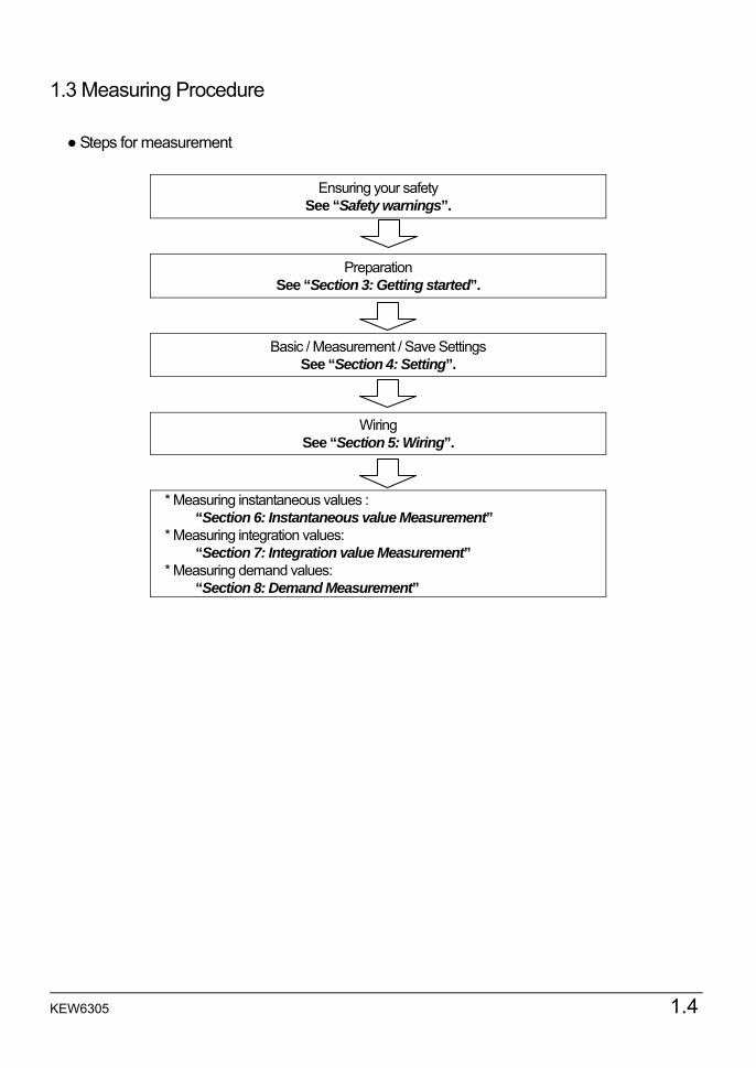
1.3 Measuring Procedure
Steps for measurement
Ensuring your safety See “Safety warnings”.
Preparation See “Section 3: Getting started”.
Basic / Measurement / Save Settings See “Section 4: Setting”.
Wiring See “Section 5: Wiring”.
* Measuring instantaneous values : “Section 6: Instantaneous value Measurement”
* Measuring integration values: “Section 7: Integration value Measurement”
* Measuring demand values: “Section 8: Demand Measurement”
1.5 KEW6305
1.4 Outline of max demand measurement concept
In some countries, large consumers of electricity will usually have a maximum demand contract with the power company. Such contract varies from country to country. The following is an explanation of a typical Japanese maximum demand contract. Maximum Demand contract In such a contract the electricity tariff rates (i.e. for kWhr units) are based upon the consumer’s maximum power demand. The maximum demand is the maximum of average powers recorded over a 30min intervals. This is measured by the maximum demand meter belonging to the power company. Let’s assume that a power company has the following applicable rates. $2 per KWhr unit for a recorded max demand 300KW during a year $4 per KWhr unit for a recorded max demand 500KW during a year $5 per KWhr unit for a recorded max demand 600KW during a year Assuming that the consumer is on the 500kW/year rate (ie. $4), and the recorded max demand during a particular day(say 15th January) is 600kW . Then the new applicable rate from 1st February onwards will be the 600kW/year rate (ie. $5) for the next 365 days. If a year later, on February 1st the recorded maximum demand is 300kW, then the new applicable rates will be changed to 300kW/year rate (i.e. $2) for the subsequent 365 days. However if during this period, the max demand goes up again, and say 600kW is recorded on 15th March, the applicable rates change again to the 600kW/year rate (i.e.$5) for the subsequent 365 days. Benefits of maximum demand control It is thus important for consumers with such contracts to monitor closely fluctuations in their power demand to ensure that their max demand limits are not exceeded and thus incur higher tariffs. Maximum Demand control is more effective in countries with higher electricity tariffs. Status of maximum demand contract In the past, in Japan, only consumers whose electricity supply was rated at 600kW or more used to enter into a demand contract. However, nowadays power companies install maximum demand meters at all consumers whose supply is rated 70kW or more. Maximum Demand measurement limitations N.B. The readings from power company maximum demand meter and from the 6300 will not match completely due to an obvious time-lag difference in the start of the integration period (eg.30mins) over which the max demand is taken.

KEW6305 1.6
2.1 KEW6305
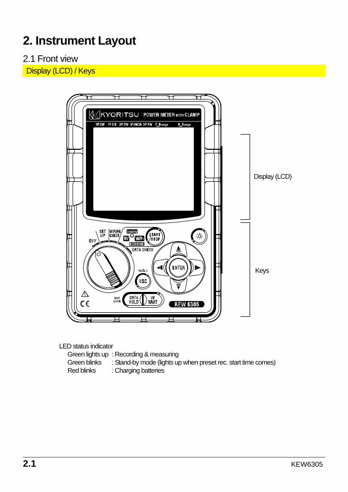
Display (LCD)
Keys
LED status indicator Green lights up : Recording & measuring Green blinks : Stand-by mode (lights up when preset rec. start time comes) Red blinks : Charging batteries
2. Instrument Layout 2.1 Front view Display (LCD) / Keys
KEW6305 2.2
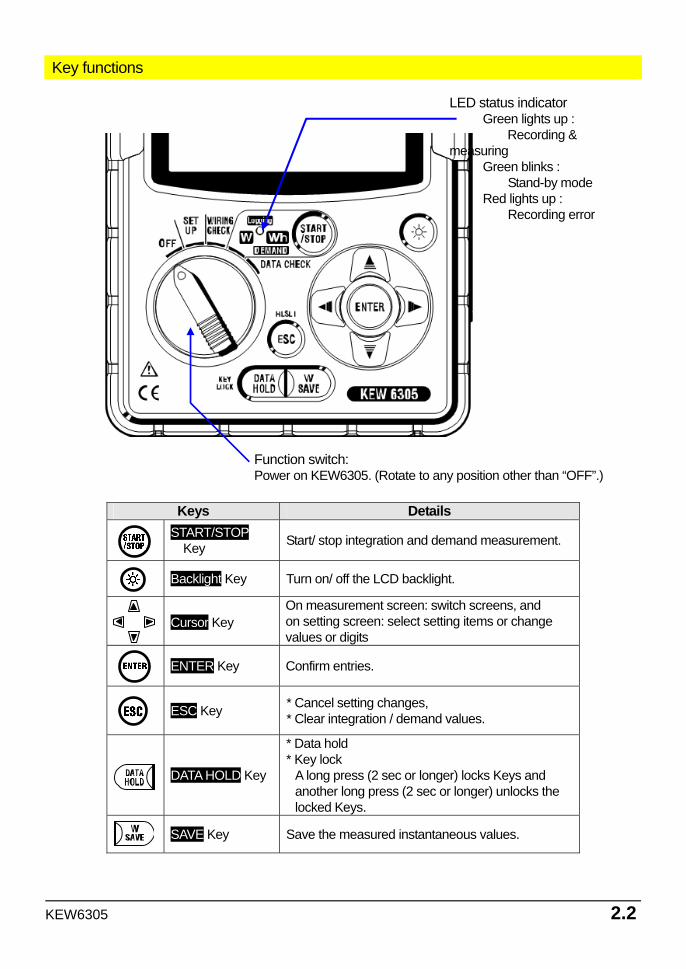
Function switch: Power on KEW6305. (Rotate to any position other than “OFF”.)
Key functions
Keys Details START/STOP
Key Start/ stop integration and demand measurement.
Backlight Key Turn on/ off the LCD backlight.
Cursor Key
On measurement screen: switch screens, and on setting screen: select setting items or change values or digits
ENTER Key Confirm entries.
ESC Key * Cancel setting changes,
* Clear integration / demand values.
DATA HOLD Key
* Data hold * Key lock A long press (2 sec or longer) locks Keys and another long press (2 sec or longer) unlocks the locked Keys.
SAVE Key Save the measured instantaneous values.
LED status indicator Green lights up :
Recording & measuring
Green blinks : Stand-by mode
Red lights up : Recording error
2.3 KEW6305
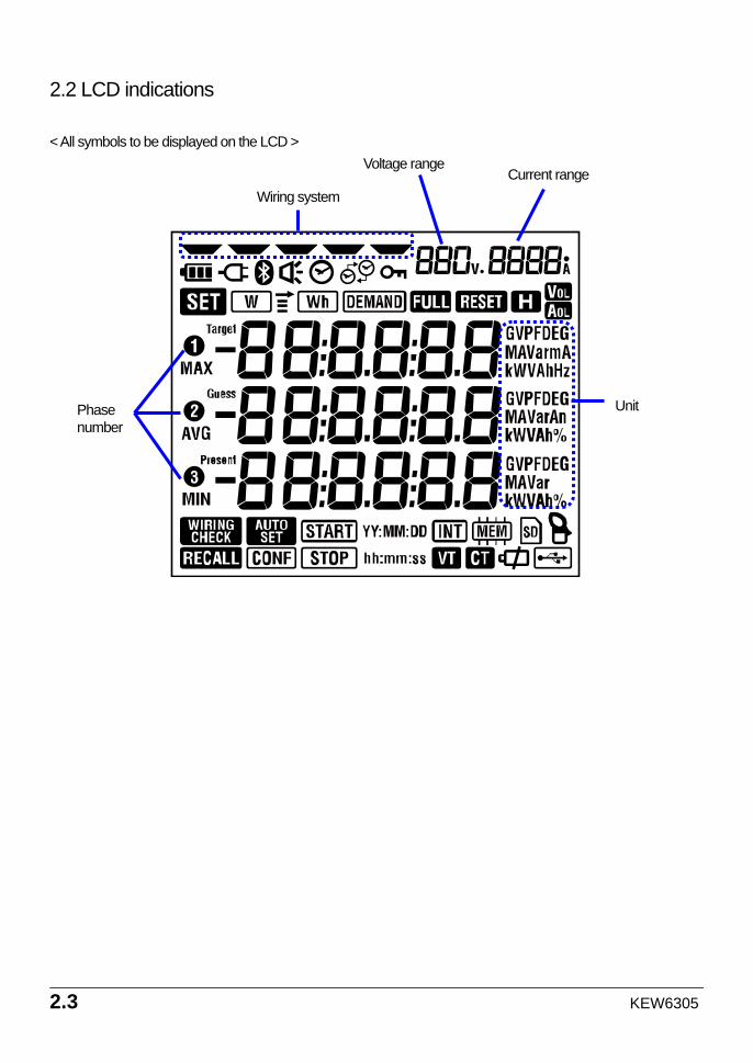
2.2 LCD indications < All symbols to be displayed on the LCD >
Unit Phase number
Wiring system Current range
Voltage range
KEW6305 2.4
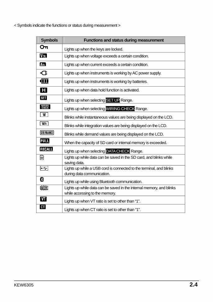
< Symbols indicate the functions or status during measurement >
Symbols Functions and status during measurement
Lights up when the keys are locked.
Lights up when voltage exceeds a certain condition.
Lights up when current exceeds a certain condition.
Lights up when instruments is working by AC power supply.
Lights up when instruments is working by batteries.
Lights up when data hold function is activated.
Lights up when selecting SET UP Range.
Lights up when selecting WIRING CHECK Range.
Blinks while instantaneous values are being displayed on the LCD.
Blinks while integration values are being displayed on the LCD.
Blinks while demand values are being displayed on the LCD.
When the capacity of SD card or internal memory is exceeded.
Lights up when selecting DATA CHECK Range.
Lights up while data can be saved in the SD card, and blinks while saving data.
Lights up while a USB cord is connected to the terminal, and blinks during data communication.
Lights up while using Bluetooth communication.
Lights up while data can be saved in the internal memory, and blinks while accessing to the memory.
Lights up when VT ratio is set to other than “1”.
Lights up when CT ratio is set to other than “1”.
2.5 KEW6305
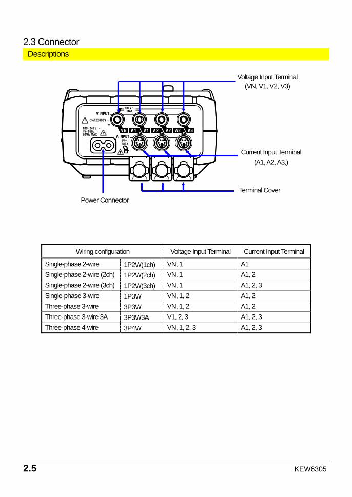
2.3 Connector Descriptions
Wiring configuration Voltage Input Terminal Current Input Terminal
Single-phase 2-wire 1P2W(1ch) VN, 1 A1 Single-phase 2-wire (2ch) 1P2W(2ch) VN, 1 A1, 2 Single-phase 2-wire (3ch) 1P2W(3ch) VN, 1 A1, 2, 3 Single-phase 3-wire 1P3W VN, 1, 2 A1, 2 Three-phase 3-wire 3P3W VN, 1, 2 A1, 2 Three-phase 3-wire 3A 3P3W3A V1, 2, 3 A1, 2, 3 Three-phase 4-wire 3P4W VN, 1, 2, 3 A1, 2, 3
Voltage Input Terminal (VN, V1, V2, V3)
Power Connector
Current Input Terminal (A1, A2, A3,)
Terminal Cover
KEW6305 2.6
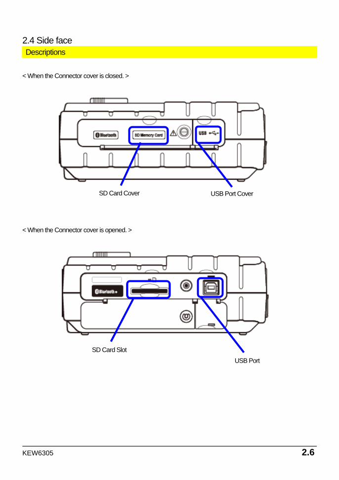
SD Card Cover USB Port Cover
SD Card Slot USB Port
2.4 Side face Descriptions
< When the Connector cover is closed. >
< When the Connector cover is opened. >
3.1 KEW6305
3. Getting started 3.1 Power Supply
3.1.1 Battery KEW6305 operates with either an AC power supply or batteries. Capable of performing measurements in the event of AC power interruption, power to the instrument is automatically restored by the batteries installed in the instrument. Dry-cell batteries (alkaline) and rechargeable batteries (Ni-MH) can be both used. * Dry-cell batteries (alkaline) are supplied as accessories.
DANGER Never open the Battery Cover during a measurement. Brand and type of the batteries to be used should be harmonized. Never touch the Power supply connector although it is insulated while the instrument is operating with batteries.
WARNING Ensure that the Power cord, Voltage test leads and Clamp sensor are removed from the instrument, and that the instrument is switched off when opening the Battery cover for battery replacement.
CAUTION Never mix new and old batteries. Install batteries in correct polarity as marked inside the Battery compartment area.
Batteries are not in the instrument at the time of purchase. Please insert the supplied batteries before starting to use the instrument. Battery power is consumed even if the instrument is being off. Remove all the batteries if the instrument is to be stored and will not be in use for a long period. When the instrument is powered by an AC power supply, it doesn’t operate with batteries. If an AC supply is interrupted and the batteries have not been inserted, the instrument goes off and all data may lost.
KEW6305 3.2
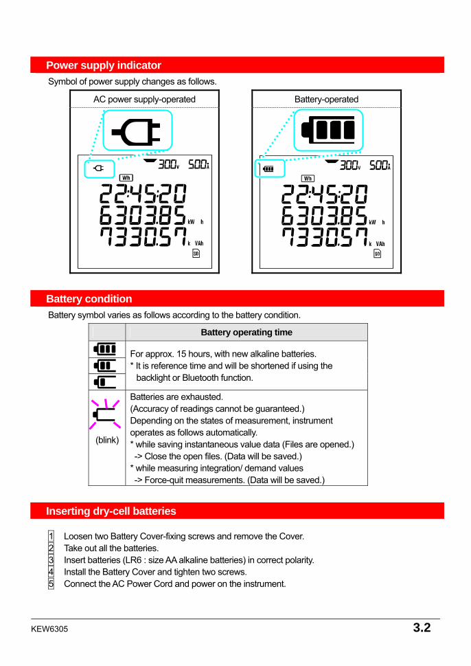
Power supply indicator Symbol of power supply changes as follows.
AC power supply-operated Battery-operated
Battery condition Battery symbol varies as follows according to the battery condition.
Battery operating time
For approx. 15 hours, with new alkaline batteries. * It is reference time and will be shortened if using the
backlight or Bluetooth function.
(blink)
Batteries are exhausted. (Accuracy of readings cannot be guaranteed.) Depending on the states of measurement, instrument operates as follows automatically. * while saving instantaneous value data (Files are opened.) -> Close the open files. (Data will be saved.) * while measuring integration/ demand values -> Force-quit measurements. (Data will be saved.)
Inserting dry-cell batteries 1 Loosen two Battery Cover-fixing screws and remove the Cover. 2 Take out all the batteries. 3 Insert batteries (LR6 : size AA alkaline batteries) in correct polarity. 4 Install the Battery Cover and tighten two screws. 5 Connect the AC Power Cord and power on the instrument.
3.3 KEW6305
3.1.2 AC Power supply
Check the followings before connecting the Power cord.
DANGER Use only the Power cord supplied with this instrument. Connect the Power cord mains plug to a mains socket outlet. The mains supply voltage must not exceed AC240V. (max rated voltage of supplied Power cord MODEL7169 : AC125V)
WARNING
Confirm that the instrument is powered off, and then connect the Power cord. Connect the Power cord to the instrument first. Cord to be firmly inserted. Never attempt to make measurement if any abnormal conditions such as abnormal conditions are noted, such as a broken Cover and exposed metal parts. When the instrument is not in use, disconnect the Power cord from the outlet. When unplugging the cord from the mains socket outlet, do so by removing the plug first and not by pulling the cord.
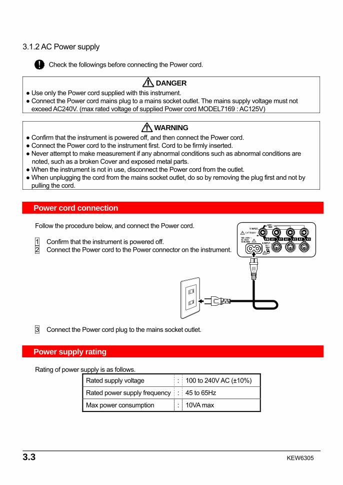
Power cord connection Follow the procedure below, and connect the Power cord. 1 Confirm that the instrument is powered off. 2 Connect the Power cord to the Power connector on the instrument. 3 Connect the Power cord plug to the mains socket outlet.
Power supply rating Rating of power supply is as follows.
Rated supply voltage : 100 to 240V AC (±10%)
Rated power supply frequency : 45 to 65Hz
Max power consumption : 10VA max
KEW6305 3.4
3.2 Voltage test leads and Clamp sensor connection
Check the followings before connecting the test leads and sensors.
DANGER Use only the Voltage test leads supplied with this instrument. Use the dedicated Clamp sensor for this instrument, and confirm that the measured current rating of the Clamp sensor is not exceeded. Do not connect all the Voltage test leads or Clamp sensors unless required for measuring the parameters desired. Connect the test leads and sensors to the instrument first, and only then connect them to the circuit under test. Never disconnect the Voltage test leads and sensors while the instrument is in use.
WARNING
Confirm that the instrument is powered off, and then connect the Power cord. Connect the Power cord to the instrument first. Cord to be firmly inserted. Never attempt to make measurement if any abnormal conditions such as abnormal conditions are noted, such as a broken Cover and exposed metal parts.
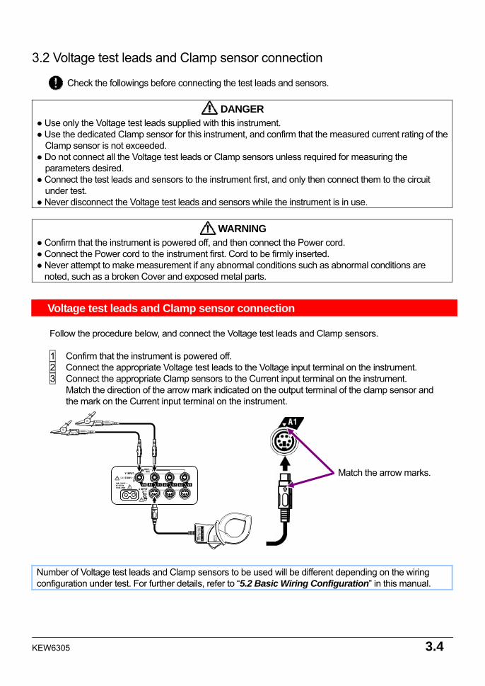
Voltage test leads and Clamp sensor connection Follow the procedure below, and connect the Voltage test leads and Clamp sensors. 1 Confirm that the instrument is powered off. 2 Connect the appropriate Voltage test leads to the Voltage input terminal on the instrument. 3 Connect the appropriate Clamp sensors to the Current input terminal on the instrument. Match the direction of the arrow mark indicated on the output terminal of the clamp sensor and the mark on the Current input terminal on the instrument.
Number of Voltage test leads and Clamp sensors to be used will be different depending on the wiring configuration under test. For further details, refer to “5.2 Basic Wiring Configuration” in this manual.
Match the arrow marks.
3.5 KEW6305
3.3 Start KEW6305
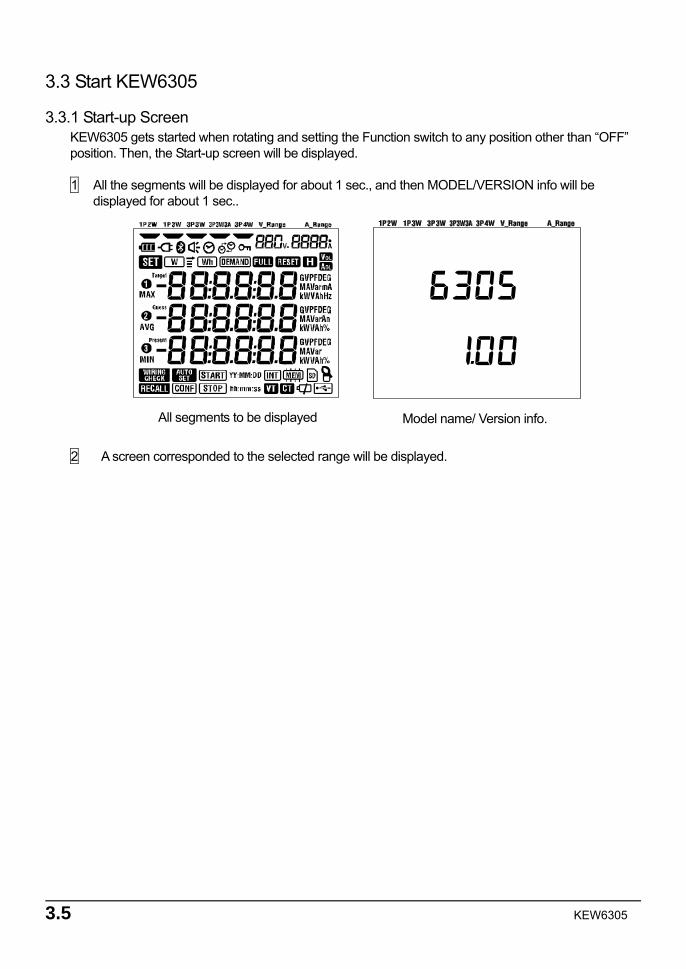
3.3.1 Start-up Screen KEW6305 gets started when rotating and setting the Function switch to any position other than “OFF” position. Then, the Start-up screen will be displayed. 1 All the segments will be displayed for about 1 sec., and then MODEL/VERSION info will be displayed for about 1 sec.. 2 A screen corresponded to the selected range will be displayed.
All segments to be displayed Model name/ Version info.
KEW6305 3.6
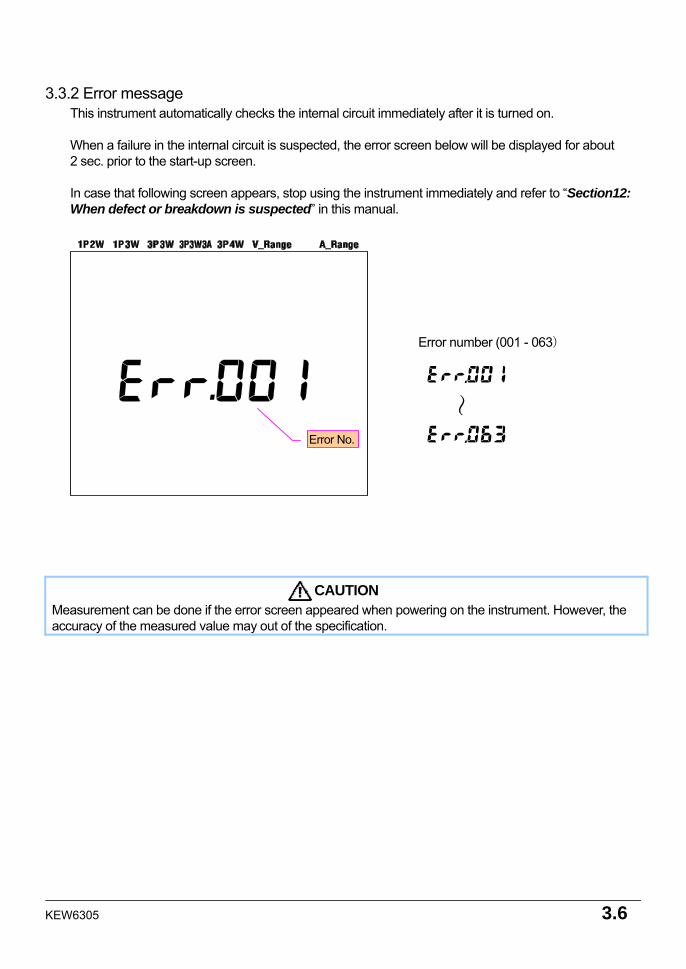
Error number (001 - 063)
3.3.2 Error message This instrument automatically checks the internal circuit immediately after it is turned on. When a failure in the internal circuit is suspected, the error screen below will be displayed for about 2 sec. prior to the start-up screen. In case that following screen appears, stop using the instrument immediately and refer to “Section12: When defect or breakdown is suspected” in this manual.
CAUTION Measurement can be done if the error screen appeared when powering on the instrument. However, the accuracy of the measured value may out of the specification.
Error No.
~
4.1 KEW6305
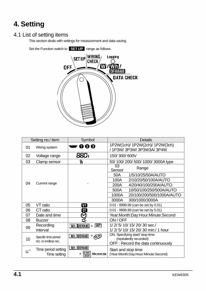
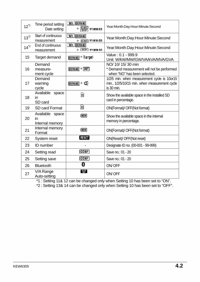
4. Setting 4.1 List of setting items
This section deals with settings for measurement and data saving. Set the Function switch to SET UP range as follows.
Setting no./ item Symbol Details
01 Wiring system 1P2W(1ch)/ 1P2W(2ch)/ 1P2W(3ch) / 1P3W/ 3P3W/ 3P3W3A/ 3P4W
02 Voltage range 150/ 300/ 600V 03 Clamp sensor 50/ 100/ 200/ 500/ 1000/ 3000A type
03 Sensor Range
50A 1/5/10/25/50A/AUTO 100A 2/10/20/50/100A/AUTO 200A 4/20/40/100/200A/AUTO 500A 10/50/100/250/500A/AUTO 1000A 20/100/200/500/1000A/AUTO
04 Current range -
3000A 300/1000/3000A 05 VT ratio 0.01 - 9999.99 (can be set by 0.01) 06 CT ratio 0.01 - 9999.99 (can be set by 0.01) 07 Date and time Year:Month:Day:Hour:Minute:Second 08 Buzzer ON / OFF
09 Recording interval
1/ 2/ 5/ 10/ 15/ 20/ 30 sec./ 1/ 2/ 5/ 10/ 15/ 20/ 30 min./ 1 hour
10 Specific time period rec. or endless rec.
ON: Specifying start/ stop time (repeatedly recorded)
OFF : Record the data continuously
11*1 Time period settingTime setting
Start and stop time (Year:Month:Day:Hour:Minute:Second)
+
+
+
KEW6305 4.2
12*1 Time period settingDate setting
Year:Month:Day:Hour:Minute:Second
13*2 Start of continuous measurement
Year:Month:Day:Hour:Minute:Second
14*2 End of continuous measurement
Year:Month:Day:Hour:Minute:Second
15 Target demand Value : 0.1 - 999.9 Unit: W/kW/MW/GW/VA/kVA/MVA/GVA
16 Demand measure- ment cycle
NO/ 10/ 15/ 30 min * Demand measurement will not be performed
when “NO” has been selected.
17 Demand warning cycle
1/2/5 min. when measurement cycle is 10or15 min., 1/2/5/10/15 min. when measurement cycle is 30 min.
18 Available space in SD card
Show the available space in the installed SD card in percentage.
19 SD card Format ON(Format)/ OFF(Not format)
20 Available space in Internal memory
Show the available space in the internal memory in percentage.
21 Internal memory Format
ON(Format)/ OFF(Not format)
22 System reset ON(Reset)/ OFF(Not reset)
23 ID number - Designate ID no. (00-001 - 99-999)
24 Setting read Save no.: 01 - 20 25 Setting save Save no.: 01 - 20
26 Bluetooth ON/ OFF
27 V/A Range Auto-setting
ON/ OFF
*1 : Setting 11& 12 can be changed only when Setting 10 has been set to “ON”. *2 : Setting 13& 14 can be changed only when Setting 10 has been set to “OFF”.
+
+
+ +
+
+
4.3 KEW6305
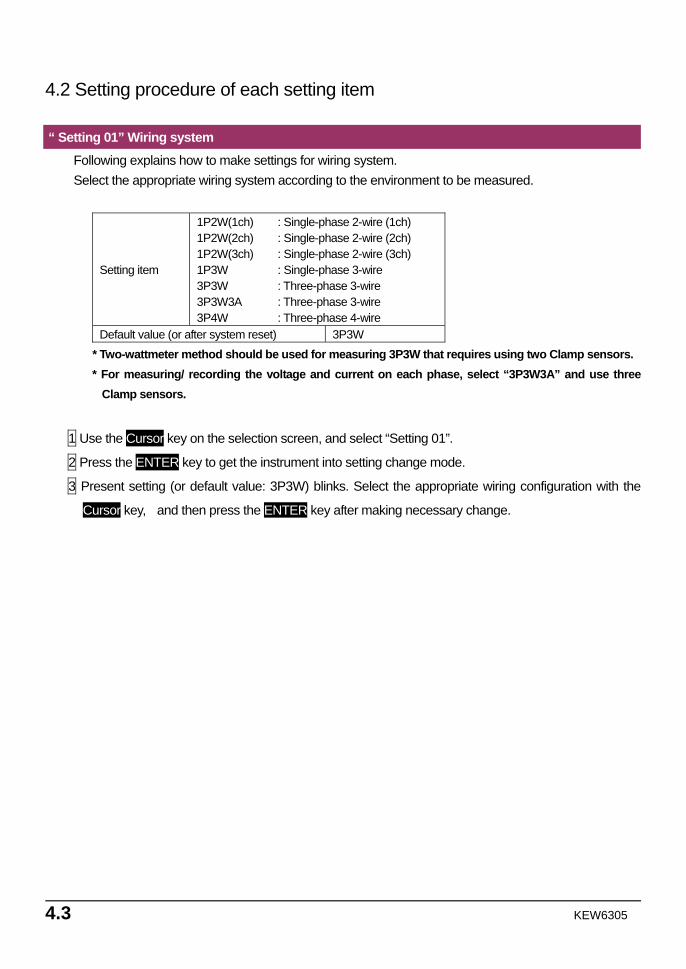
4.2 Setting procedure of each setting item
“ Setting 01” Wiring system Following explains how to make settings for wiring system. Select the appropriate wiring system according to the environment to be measured.
Setting item
1P2W(1ch) : Single-phase 2-wire (1ch) 1P2W(2ch) : Single-phase 2-wire (2ch) 1P2W(3ch) : Single-phase 2-wire (3ch) 1P3W : Single-phase 3-wire 3P3W : Three-phase 3-wire 3P3W3A : Three-phase 3-wire 3P4W : Three-phase 4-wire
Default value (or after system reset) 3P3W * Two-wattmeter method should be used for measuring 3P3W that requires using two Clamp sensors. * For measuring/ recording the voltage and current on each phase, select “3P3W3A” and use three
Clamp sensors.
1 Use the Cursor key on the selection screen, and select “Setting 01”.
2 Press the ENTER key to get the instrument into setting change mode.
3 Present setting (or default value: 3P3W) blinks. Select the appropriate wiring configuration with the
Cursor key, and then press the ENTER key after making necessary change.
KEW6305 4.4
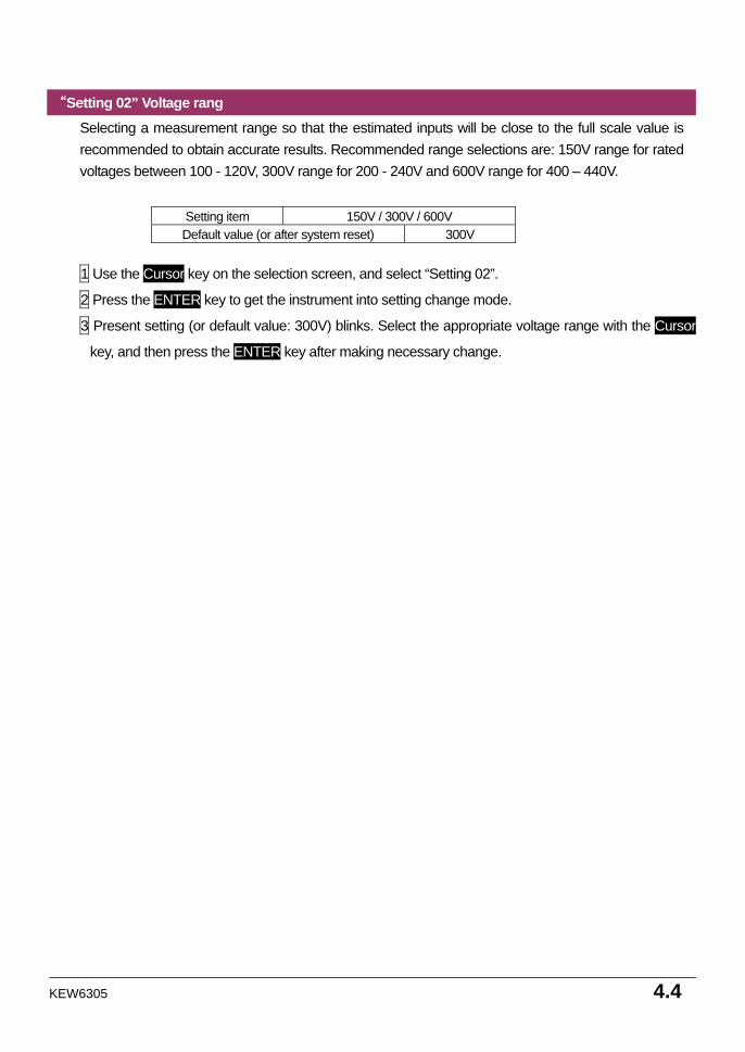
“Setting 02” Voltage rang Selecting a measurement range so that the estimated inputs will be close to the full scale value is recommended to obtain accurate results. Recommended range selections are: 150V range for rated voltages between 100 - 120V, 300V range for 200 - 240V and 600V range for 400 – 440V.
Setting item 150V / 300V / 600V Default value (or after system reset) 300V
1 Use the Cursor key on the selection screen, and select “Setting 02”.
2 Press the ENTER key to get the instrument into setting change mode.
3 Present setting (or default value: 300V) blinks. Select the appropriate voltage range with the Cursor
key, and then press the ENTER key after making necessary change.
4.5 KEW6305
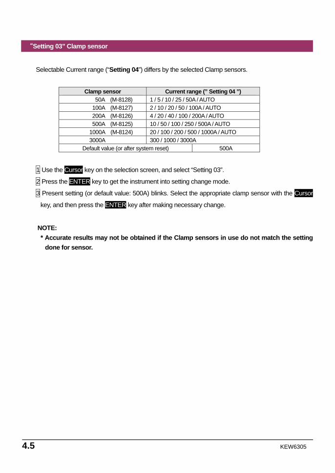
“Setting 03” Clamp sensor
Selectable Current range (“Setting 04”) differs by the selected Clamp sensors.
Clamp sensor Current range (” Setting 04 ”)
50A (M-8128) 1 / 5 / 10 / 25 / 50A / AUTO 100A (M-8127) 2 / 10 / 20 / 50 / 100A / AUTO 200A (M-8126) 4 / 20 / 40 / 100 / 200A / AUTO 500A (M-8125) 10 / 50 / 100 / 250 / 500A / AUTO 1000A (M-8124) 20 / 100 / 200 / 500 / 1000A / AUTO 3000A 300 / 1000 / 3000A
Default value (or after system reset) 500A
1 Use the Cursor key on the selection screen, and select “Setting 03”.
2 Press the ENTER key to get the instrument into setting change mode.
3 Present setting (or default value: 500A) blinks. Select the appropriate clamp sensor with the Cursor
key, and then press the ENTER key after making necessary change.
NOTE: * Accurate results may not be obtained if the Clamp sensors in use do not match the setting
done for sensor.
KEW6305 4.6
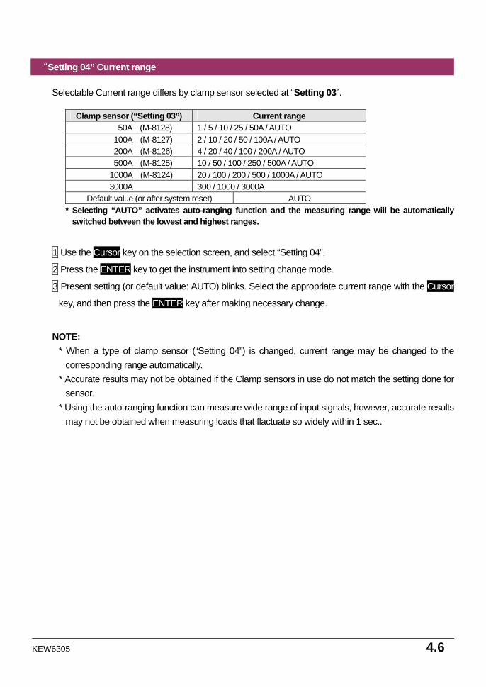
“Setting 04” Current range
Selectable Current range differs by clamp sensor selected at “Setting 03”.
Clamp sensor (“Setting 03”) Current range 50A (M-8128) 1 / 5 / 10 / 25 / 50A / AUTO 100A (M-8127) 2 / 10 / 20 / 50 / 100A / AUTO 200A (M-8126) 4 / 20 / 40 / 100 / 200A / AUTO 500A (M-8125) 10 / 50 / 100 / 250 / 500A / AUTO 1000A (M-8124) 20 / 100 / 200 / 500 / 1000A / AUTO 3000A 300 / 1000 / 3000A
Default value (or after system reset) AUTO * Selecting “AUTO” activates auto-ranging function and the measuring range will be automatically
switched between the lowest and highest ranges.
1 Use the Cursor key on the selection screen, and select “Setting 04”.
2 Press the ENTER key to get the instrument into setting change mode.
3 Present setting (or default value: AUTO) blinks. Select the appropriate current range with the Cursor
key, and then press the ENTER key after making necessary change.
NOTE: * When a type of clamp sensor (“Setting 04”) is changed, current range may be changed to the
corresponding range automatically. * Accurate results may not be obtained if the Clamp sensors in use do not match the setting done for
sensor. * Using the auto-ranging function can measure wide range of input signals, however, accurate results
may not be obtained when measuring loads that flactuate so widely within 1 sec..
4.7 KEW6305
150V 300V 600V 1P2W 1P3W 3P3W 3P4W
5A 10A 20A 50A 100A 200A 500A 1000A
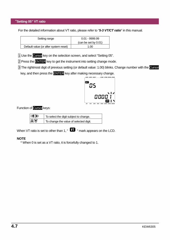
“Setting 05” VT ratio
For the detailed information about VT ratio, please refer to “5-3 VT/CT ratio” in this manual.
Setting range 0.01 - 9999.99 (can be set by 0.01)
Default value (or after system reset) 1.00
1 Use the Cursor key on the selection screen, and select “Setting 05”.
2 Press the ENTER key to get the instrument into setting change mode.
3 The rightmost digit of previous setting (or default value: 1.00) blinks. Change number with the Cursor
key, and then press the ENTER key after making necessary change.
Function of Cursor keys:
To select the digit subject to change. To change the value of selected digit.
When VT ratio is set to other than 1, “ “ mark appears on the LCD. NOTE
* When 0 is set as a VT ratio, it is forcefully changed to 1.
KEW6305 4.8
150V 300V 600V 1P2W 1P3W 3P3W 3P4W
5A 10A 20A 50A 100A 200A 500A 1000A
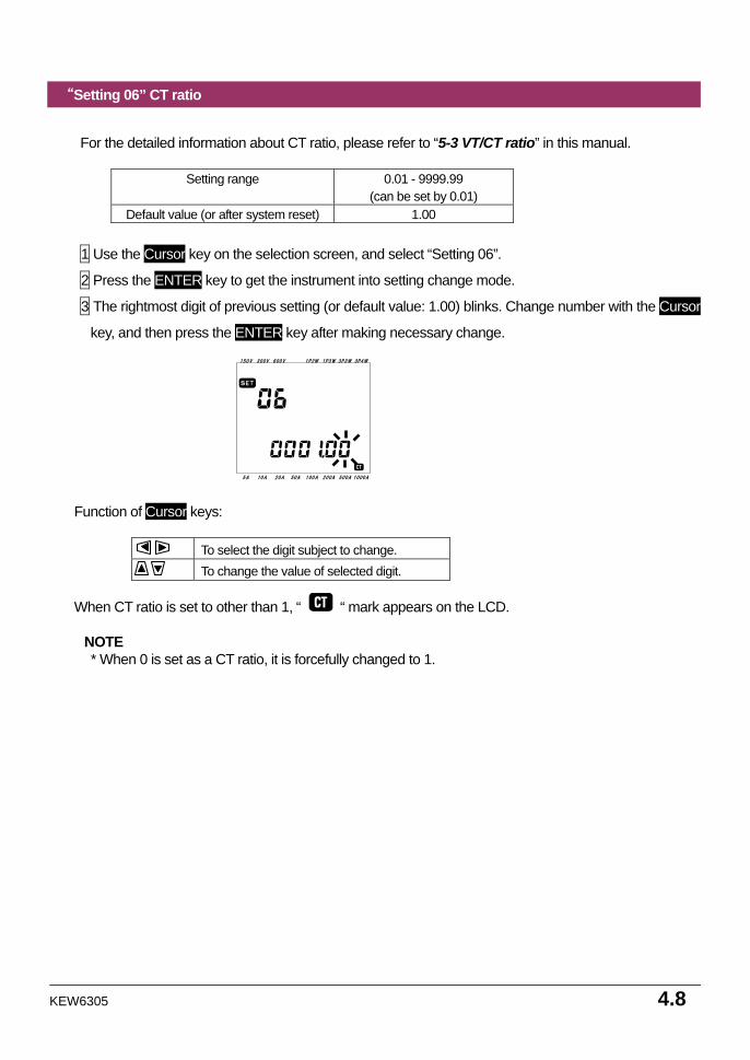
“Setting 06” CT ratio
For the detailed information about CT ratio, please refer to “5-3 VT/CT ratio” in this manual.
Setting range 0.01 - 9999.99
(can be set by 0.01) Default value (or after system reset) 1.00
1 Use the Cursor key on the selection screen, and select “Setting 06”.
2 Press the ENTER key to get the instrument into setting change mode.
3 The rightmost digit of previous setting (or default value: 1.00) blinks. Change number with the Cursor
key, and then press the ENTER key after making necessary change.
Function of Cursor keys:
To select the digit subject to change. To change the value of selected digit.
When CT ratio is set to other than 1, “ “ mark appears on the LCD.
NOTE * When 0 is set as a CT ratio, it is forcefully changed to 1.
4.9 KEW6305
150V 300V 600V 1P2W 1P3W 3P3W 3P4W
5A 10A 20A 50A 100A 200A 500A 1000A
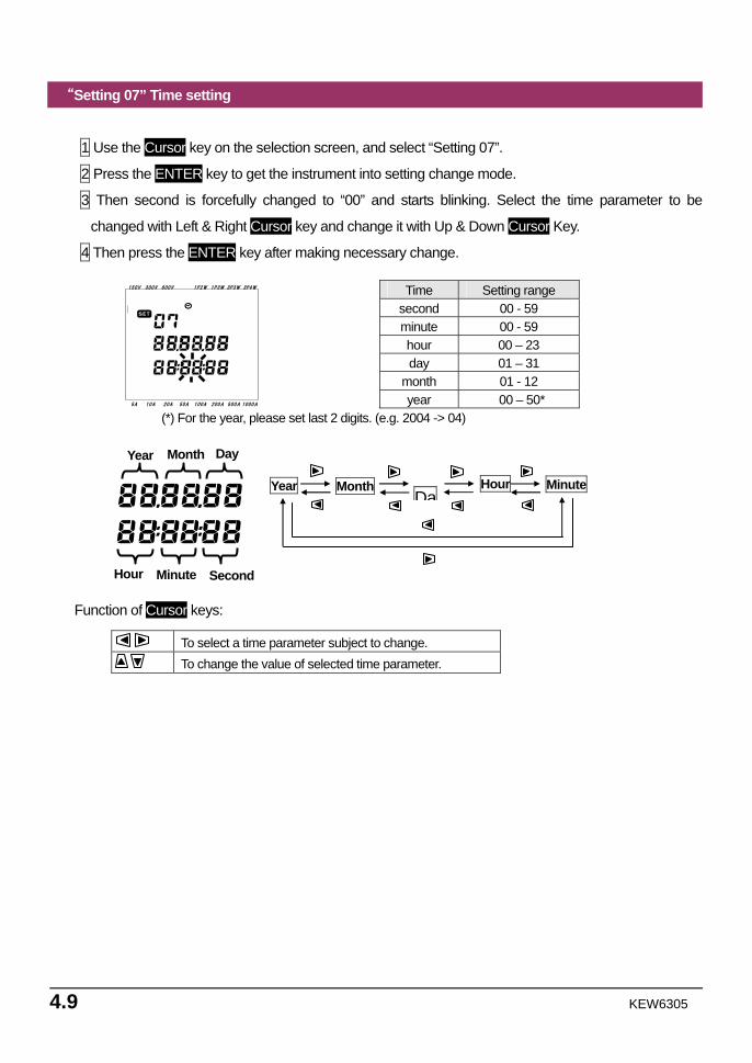
“Setting 07” Time setting
1 Use the Cursor key on the selection screen, and select “Setting 07”.
2 Press the ENTER key to get the instrument into setting change mode.
3 Then second is forcefully changed to “00” and starts blinking. Select the time parameter to be
changed with Left & Right Cursor key and change it with Up & Down Cursor Key.
4 Then press the ENTER key after making necessary change.
Time Setting range second 00 - 59 minute 00 - 59 hour 00 – 23 day 01 – 31
month 01 - 12
year 00 – 50* (*) For the year, please set last 2 digits. (e.g. 2004 -> 04)
Function of Cursor keys:
To select a time parameter subject to change. To change the value of selected time parameter.
Year Month Hour Da
Minute
Year Month
Hour Minute
Day
Second
KEW6305 4.10
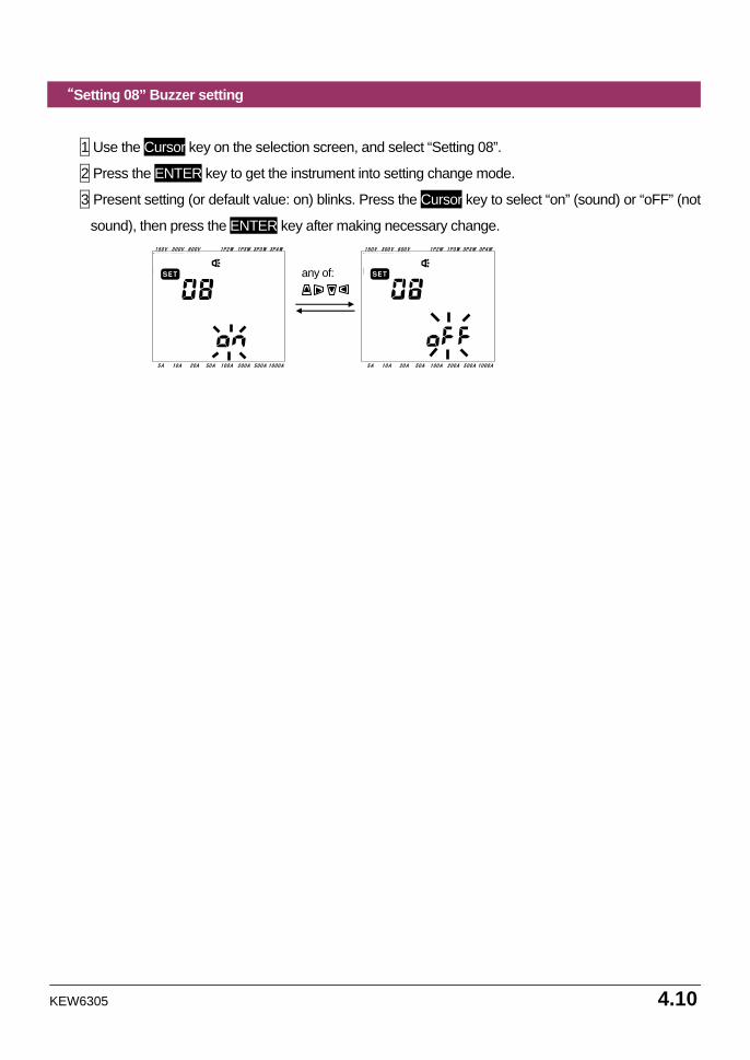
“Setting 08” Buzzer setting
1 Use the Cursor key on the selection screen, and select “Setting 08”.
2 Press the ENTER key to get the instrument into setting change mode.
3 Present setting (or default value: on) blinks. Press the Cursor key to select “on” (sound) or “oFF” (not
sound), then press the ENTER key after making necessary change.
150V 300V 600V 1P2W 1P3W 3P3W 3P4W
5A 10A 20A 50A 100A 200A 500A 1000A
150V 300V 600V 1P2W 1P3W 3P3W 3P4W
5A 10A 20A 50A 100A 200A 500A 1000A
any of:
4.11 KEW6305
150V 300V 600V 1P2W 1P3W 3P3W 3P4W
5A 10A 20A 50A 100A 200A 500A 1000A
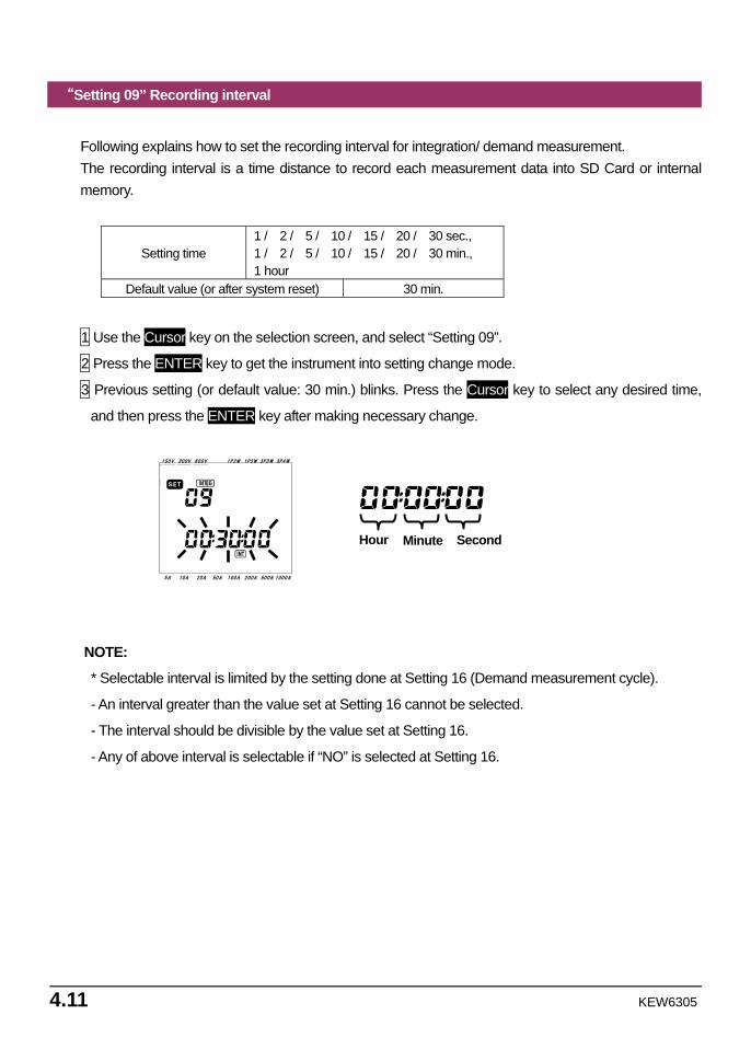
“Setting 09” Recording interval
Following explains how to set the recording interval for integration/ demand measurement. The recording interval is a time distance to record each measurement data into SD Card or internal memory.
Setting time 1 / 2 / 5 / 10 / 15 / 20 / 30 sec., 1 / 2 / 5 / 10 / 15 / 20 / 30 min., 1 hour
Default value (or after system reset) 30 min.
1 Use the Cursor key on the selection screen, and select “Setting 09”.
2 Press the ENTER key to get the instrument into setting change mode.
3 Previous setting (or default value: 30 min.) blinks. Press the Cursor key to select any desired time,
and then press the ENTER key after making necessary change.
NOTE:
* Selectable interval is limited by the setting done at Setting 16 (Demand measurement cycle).
- An interval greater than the value set at Setting 16 cannot be selected.
- The interval should be divisible by the value set at Setting 16.
- Any of above interval is selectable if “NO” is selected at Setting 16.
Hour Minute Second
KEW6305 4.12
“Setting 10” Specific time period rec. or endless rec.
1 Use the Cursor key on the selection screen, and select “Setting 10”.
2 Press the ENTER key to get the instrument into setting change mode.
3 Present setting (or default value: OFF) blinks. Press the Cursor key to select “ON” or “OFF”.
ON : Specify the recording start / stop time (repeatedly recorded).
OFF : Record the data continuously.
4 Press the ENTER key after making necessary change.
NOTE: * Setting screens for Setting 11 to 14 may not be displayed according to the setting done at Setting
10. - When Setting 10 has been set to “ON”, setting screens for Setting 11 and 12 will be displayed but
for Setting 13 and 14 will not be displayed. - When Setting 10 has been set to “OFF”, setting screens for Setting 13 and 14 will be displayed but
for Setting 11 and 12 will not be displayed.
4.13 KEW6305
“Setting 11” Time period setting (Time setting)
Following explains how to set recording start / stop time.
1 Use the Cursor key on the selection screen, and select “Setting 11”.
2 Press the ENTER key to get the instrument into setting change mode.
3 Then second for recording stop time will blink.
4 Select the time parameter to be changed and change it with Cursor Key.
5 Then press the ENTER key after making necessary change.
* Start time is displayed on the upper line and stop time is on the lower line.
NOTE:
This setting item will not be displayed if Setting 10 has been set to “OFF”.
KEW6305 4.14
“Setting 12” Time period setting (Date setting)
Following explains how to set recording start / stop date.
1 Use the Cursor key on the selection screen, and select “Setting 12”.
2 Press the ENTER key to get the instrument into setting change mode.
3 Then day for recording stop date will blink.
4 Press the Cursor Key and select any desired date.
5 Then press the ENTER key after making necessary change.
* Start date is displayed on the upper line and stop date is on the lower line.
Example:
When recording start / stop time and date have been set as follows,
Setting 11 (time) = 8:00:00 - 18:00:00
Setting 12 (date) = 12.08.01 - 12.08.07
the instrument automatically performs recording at the following time and date.
1. 8:00 to 18:00 on August 1, 2012,
2. 8:00 to 18:00 on August 2, 2012,
3. 8:00 to 18:00 on August 3, 2012,
4. 8:00 to 18:00 on August 4, 2012,
5. 8:00 to 18:00 on August 5, 2012,
6. 8:00 to 18:00 on August 6, 2012 and
7. 8:00 to 18:00 on August 7, 2012.
NOTE:
This setting item will not be displayed if Setting 10 has been set to “OFF”.
4.15 KEW6305
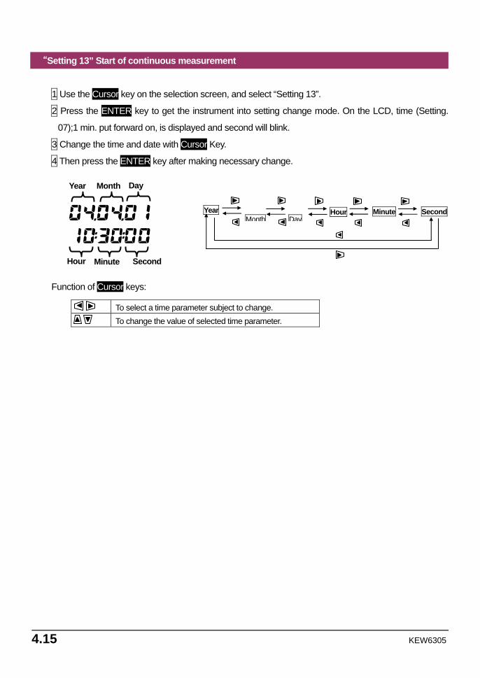
“Setting 13” Start of continuous measurement
1 Use the Cursor key on the selection screen, and select “Setting 13”.
2 Press the ENTER key to get the instrument into setting change mode. On the LCD, time (Setting.
07);1 min. put forward on, is displayed and second will blink.
3 Change the time and date with Cursor Key.
4 Then press the ENTER key after making necessary change.
Function of Cursor keys:
To select a time parameter subject to change. To change the value of selected time parameter.
Month
Hour Minute Second
Year Day
Second Year Hour Day
Minute Month
KEW6305 4.16
“Setting 14” Stop of continuous measurement
1 Use the Cursor key on the selection screen, and select “Setting 14”.
2 Press the ENTER key to get the instrument into setting change mode. On the LCD, measurement
start time (Setting 13) + 1 hour, is displayed and second will blink.
3 Change the time and date with Cursor Key.
4 Then press the ENTER key after making necessary change.
Example:
When start / stop time and date have been set as follows,
Setting 13 (start) = 12.08.01, 08:00:00
Setting 14 (stop) = 12.08.07, 18:00:00
the instrument automatically performs measurement during the following period.
From 8:00 on August 1, 2012 to 18:00 on August 7, 2012
NOTE:
* The stop time and date (Setting 14) should be set after the start time (Setting 13) in such a way to give enough
time to the user to complete all settings before the measurement starts.
Otherwise, an error message will be displayed on the LCD and the instrument cannot start measurement and
data recording.
When an error message appears, press the ENTER key and rotate the Function switch to the SETUP range to
redo settings.
4.17 KEW6305
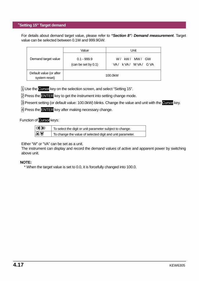
“Setting 15” Target demand
For details about demand target value, please refer to “Section 8”: Demand measurement. Target value can be selected between 0.1W and 999.9GW.
Value Unit
Demand target value 0.1 - 999.9 (can be set by 0.1)
W / kW / MW / GW VA / k VA / M VA / G VA
Default value (or after system reset)
100.0kW
1 Use the Cursor key on the selection screen, and select “Setting 15”.
2 Press the ENTER key to get the instrument into setting change mode.
3 Present setting (or default value: 100.0kW) blinks. Change the value and unit with the Cursor key.
4 Press the ENTER key after making necessary change. Function of Cursor keys:
To select the digit or unit parameter subject to change. To change the value of selected digit and unit parameter.
Either “W” or “VA” can be set as a unit. The instrument can display and record the demand values of active and apparent power by switching above unit.
NOTE:
* When the target value is set to 0.0, it is forcefully changed into 100.0.
KEW6305 4.18
“Setting 16” Demand measurement cycle
Demand measurement cycle is to be used for calculating demand values.
Setting time NO / 10 / 15 / 30 min Default value (or after system reset) 30 min
* Demand measurement will not be performed when “NO” has been selected. 1 Use the Cursor key on the selection screen, and select “Setting 16”.
2 Press the ENTER key to get the instrument into setting change mode.
3 Present setting (or default value: 30 min.) blinks. Press the Cursor key and set any desired time.
4 Press the ENTER key after making necessary change.
4.19 KEW6305
“Setting 17” Demand warning cycle
The buzzer will sound when a predicted demand value exceeds a target demand value during demand measurement. For further details, please refer to “Section 8”: Demand measurement. According to the demand measurement interval, which has been set at Setting 16, warning cycle can be set to as follows.
Demand measurement cycle
“Setting 16” Warning cycle
10 / 15 min. 1 / 2 / 5 min.
30 min. 1 / 2 / 5 / 10 / 15 min.
Default value (or after system reset) 10 min. 1 Use the Cursor key on the selection screen, and select “Setting 17”.
2 Press the ENTER key to get the instrument into setting change mode.
3 Previous setting (or default value: 10 min.) blinks. Press the Cursor key to select any desired time,
and then press the ENTER key after making necessary change.
KEW6305 4.20
“Setting 18” Available space in SD card
Following explains how to check the available space in SD card.
1 Use the Cursor key on the selection screen, and select “Setting 18”.
2 Then the available space in the SD card in KEW6305 will be displayed. (0 – 100%, displayed by 1%)
* Bars (“----“) will be displayed if SD card is not inserted.
NOTE: When using a 2GB SD card, 511 files (max) can be saved in. KEW6305 cannot perform any recording if the number of saved file exceeds the limit although there is available space in the SD card.
4.21 KEW6305
“Setting 19” SD card Format
Newly purchased SD Card must be formatted before use.
For details about SD Card, please refer to “Section 9: SD Card / Internal memory” in this manual.
CAUTION Ensure that the Function switch is set to “OFF” position before placing / removing an SD Card. If an SD Card is placed / removed while the instrument is on, stored data or instrument may be damaged.
1 Confirm the Function switch is at “OFF” position, and then place an SD Card into the SD Card slot of
the instrument.
2 Set the Function switch to SET UP range.
3 On the selection screen, select “Setting 19” with Cursor key.
4 Then press the ENTER key to get the instrument in setting change mode.
5 The message “OFF”(not format) will blink. Change it to “ON”(format) with Cursor key.
(In case that no CF card is placed in the instrument, you cannot set it to “ON”.)
6 When pressing the ENTER key, format will start.
(Formatting takes a few seconds.)
7 After formatting, a message “FINISH” is displayed on the LCD. NOTE:
* Please use SD card supplied with this instrument or supplied as optional parts. * All the data in an SD card will be deleted after formatting. * Be sure to check that SD Card works properly on the well-known hardware. * As to the manipulation of SD Card, please refer to the instruction manual attached to the card. * SD cards of 2GB capacity or less will be formatted to FAT16 and the cards of 4GB or more to
FAT32.
KEW6305 4.22
“Setting 20” Available space in Internal memory
Following explains how to check the available space in the internal memory.
1 Use the Cursor key on the selection screen, and select “Setting 20”.
2 Then the available space in the internal memory of KEW6305 will be displayed. (0 – 100%, displayed
by 25%)
NOTE: The max number of files that can be saved in the internal memory is four. If any of file size exceeds 2.25MB, no more file can be saved in the memory.
4.23 KEW6305
“Setting 21” Internal memory Format 1 Use the Cursor key on the selection screen, and select “Setting 21”.
2 Then press the ENTER key to get the instrument in setting change mode.
3 The message “OFF”(not format) will blink. Change it to “ON”(format) with Cursor key.
4 When pressing the ENTER key, format will start.
(Formatting takes a few seconds.)
5 After formatting, a message “FINISH” is displayed on the LCD. NOTE:
* All the data in the internal memory will be deleted after formatting.
KEW6305 4.24
“Setting 22” System reset Following explains how to perform system reset to restore all the settings to the default. For further details about system reset, please refer to “Section 11: Additional functions” in this manual.
1 Use the Cursor key on the selection screen, and select “Setting 22”.
2 Then press the ENTER key to get the instrument in setting change mode.
3 The message “OFF”(not reset) will blink. Change it to “ON”(reset) with Cursor key.
4 When pressing the ENTER key, system reset will start.
* The setting will return to “OFF” when system reset is done.
4.25 KEW6305
“Setting 23” ID number
Setting range 00-001 - 99-999 Default value (or after system reset) 00 - 001
1 Use the Cursor key on the selection screen, and select “Setting 23”.
2 Press the ENTER key to get the instrument into setting change mode.
3 The rightmost digit of present setting (or default value: 1.00) blinks. Change number with the Cursor
key, and then press the ENTER key after making necessary change.
Function of Cursor keys:
To select the digit subject to change. To change the value of selected digit.
Any desirable number, aside from the serial number, can be assigned as an ID number and will be saved together with the recorded data file.
KEW6305 4.26
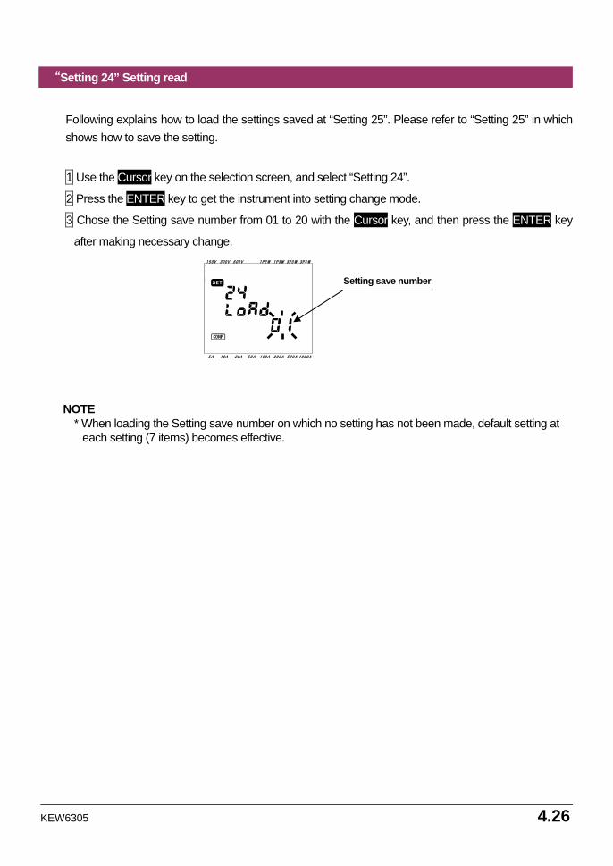
“Setting 24” Setting read
Following explains how to load the settings saved at “Setting 25”. Please refer to “Setting 25” in which shows how to save the setting.
1 Use the Cursor key on the selection screen, and select “Setting 24”.
2 Press the ENTER key to get the instrument into setting change mode.
3 Chose the Setting save number from 01 to 20 with the Cursor key, and then press the ENTER key
after making necessary change.
NOTE
* When loading the Setting save number on which no setting has not been made, default setting at each setting (7 items) becomes effective.
150V 300V 600V 1P2W 1P3W 3P3W 3P4W
5A 10A 20A 50A 100A 200A 500A 1000A
Setting save number
4.27 KEW6305
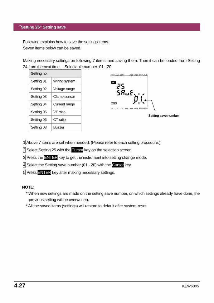
“Setting 25” Setting save
Following explains how to save the settings items. Seven items below can be saved. Making necessary settings on following 7 items, and saving them. Then it can be loaded from Setting 24 from the next time. Selectable number: 01 - 20
Setting no.
Setting 01 Wiring system
Setting 02 Voltage range
Setting 03 Clamp sensor
Setting 04 Current range
Setting 05 VT ratio
Setting 06 CT ratio
Setting 08 Buzzer
1 Above 7 items are set when needed. (Please refer to each setting procedure.)
2 Select Setting 25 with the Cursor key on the selection screen.
3 Press the ENTER key to get the instrument into setting change mode.
4 Select the Setting save number (01 - 20) with the Cursor key.
5 Press ENTER key after making necessary settings.
NOTE: * When new settings are made on the setting save number, on which settings already have done, the
previous setting will be overwritten. * All the saved items (settings) will restore to default after system-reset.
150V 300V 600V 1P2W 1P3W 3P3W 3P4W
5A 10A 20A 50A 100A 200A 500A 1000A
Setting save number
KEW6305 4.28
“Setting 26” Bluetooth
1 Use the Cursor key on the selection screen, and select “Setting 26”.
2 Press the ENTER key to get the instrument into setting change mode.
3 Present setting (or default value: OFF) blinks. Press the Cursor key to select “ON” or “OFF”, and then press the ENTER key after making necessary change.
NOTE:
To conserve battery life, it is recommended to turn off the Bluetooth function when you are not using it.
The LED (blue) lights up when “ON” is selected.
4.29 KEW6305
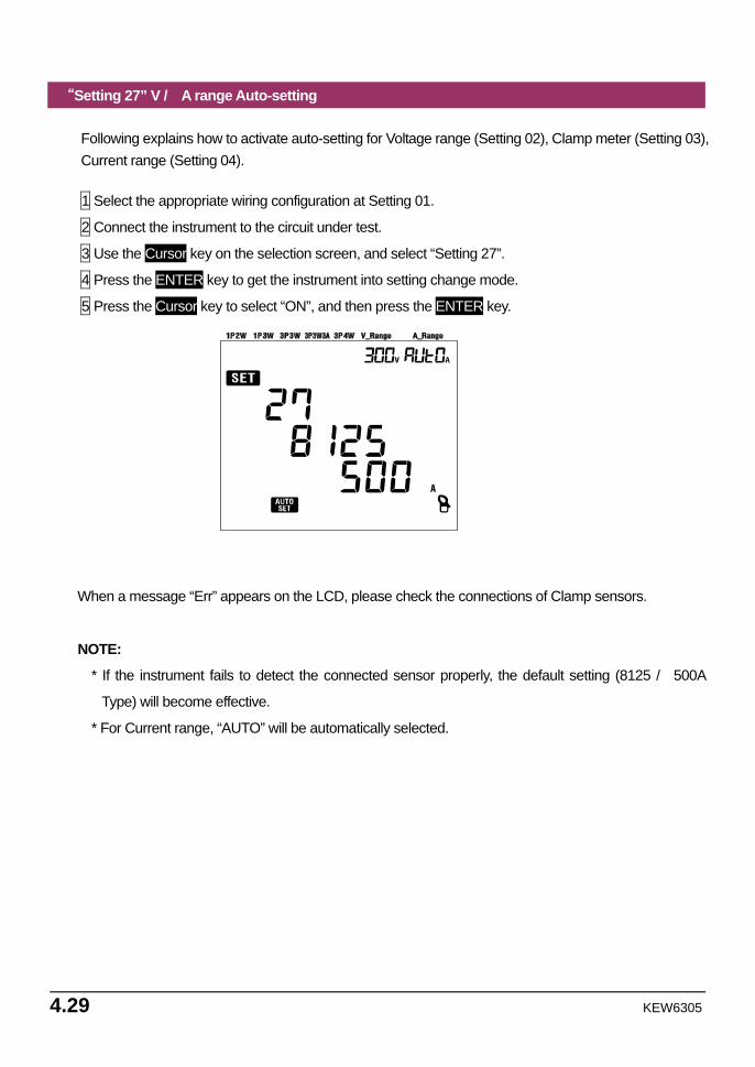
“Setting 27” V / A range Auto-setting
Following explains how to activate auto-setting for Voltage range (Setting 02), Clamp meter (Setting 03), Current range (Setting 04).
1 Select the appropriate wiring configuration at Setting 01.
2 Connect the instrument to the circuit under test.
3 Use the Cursor key on the selection screen, and select “Setting 27”.
4 Press the ENTER key to get the instrument into setting change mode.
5 Press the Cursor key to select “ON”, and then press the ENTER key.
When a message “Err” appears on the LCD, please check the connections of Clamp sensors.
NOTE:
* If the instrument fails to detect the connected sensor properly, the default setting (8125 / 500A
Type) will become effective.
* For Current range, “AUTO” will be automatically selected.

KEW6305 4.30
5.1 KEW6305
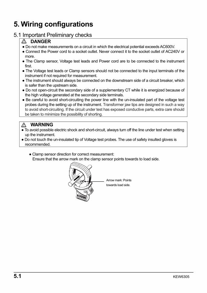
Arrow mark: Points towards load side.
5. Wiring configurations 5.1 Important Preliminary checks
DANGER Do not make measurements on a circuit in which the electrical potential exceeds AC600V. Connect the Power cord to a socket outlet. Never connect it to the socket outlet of AC240V or
more. The Clamp sensor, Voltage test leads and Power cord are to be connected to the instrument
first. The Voltage test leads or Clamp sensors should not be connected to the input terminals of the
instrument if not required for measurement. The instrument should always be connected on the downstream side of a circuit breaker, which
is safer than the upstream side. Do not open-circuit the secondary side of a supplementary CT while it is energized because of
the high voltage generated at the secondary side terminals. Be careful to avoid short-circuiting the power line with the un-insulated part of the voltage test
probes during the setting up of the instrument. Transformer jaw tips are designed in such a way to avoid short-circuiting. If the circuit under test has exposed conductive parts, extra care should be taken to minimize the possibility of shorting.
WARNING
To avoid possible electric shock and short-circuit, always turn off the line under test when setting up the instrument.
Do not touch the un-insulated tip of Voltage test probes. The use of safety insulted gloves is recommended.
Clamp sensor direction for correct measurement:
Ensure that the arrow mark on the clamp sensor points towards to load side.
KEW6305 5.2
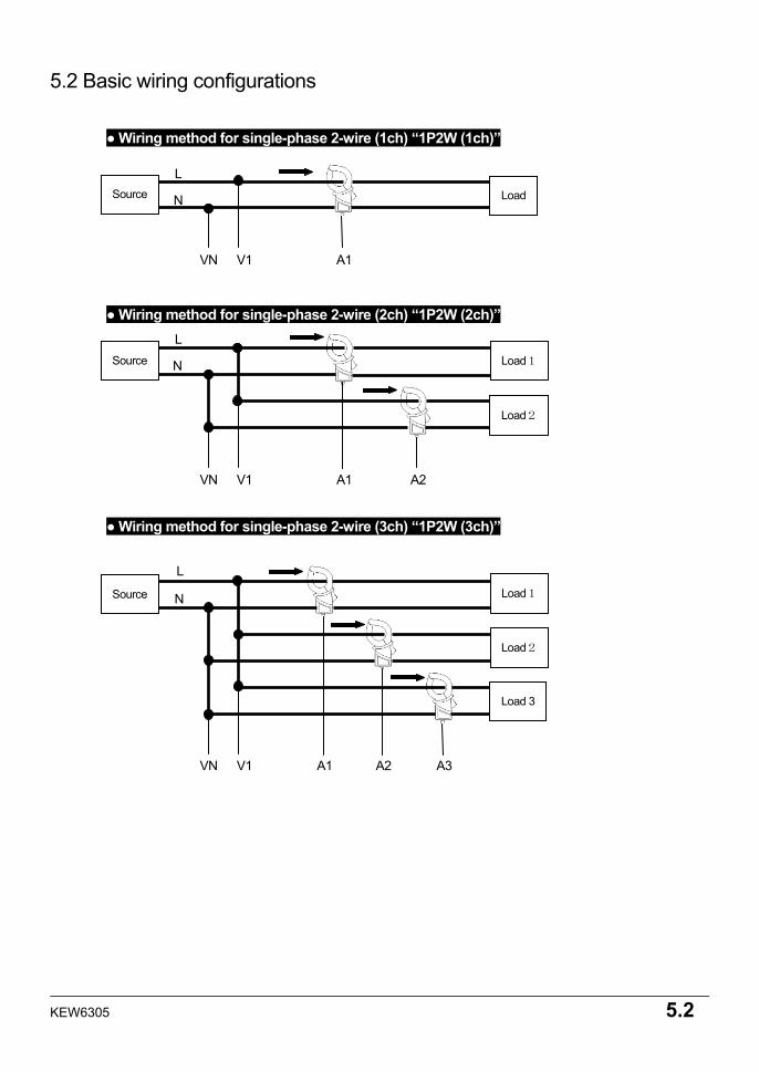
5.2 Basic wiring configurations
Wiring method for single-phase 2-wire (1ch) “1P2W (1ch)”
Wiring method for single-phase 2-wire (2ch) “1P2W (2ch)”
Wiring method for single-phase 2-wire (3ch) “1P2W (3ch)”
VN V1 A1
N
L LoadSource
VN V1 A3A2
N
L Load1
Load2
Load 3
A1
Source
VN V1 A2A1
N
L Load1
Load2
Source
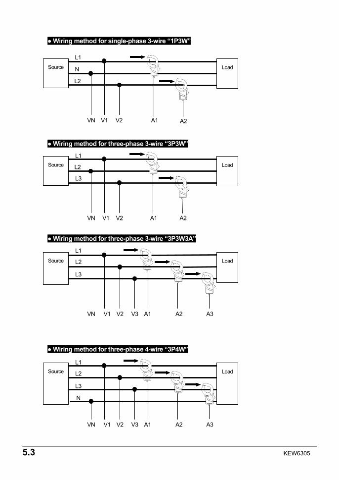
5.3 KEW6305
Wiring method for single-phase 3-wire “1P3W”
Wiring method for three-phase 3-wire “3P3W”
Wiring method for three-phase 3-wire “3P3W3A”
Wiring method for three-phase 4-wire “3P4W”
VN V1 A2A1
N
L2
LoadSource
V2
L1
VN V1 A2A1
L2
L3
Load Source
V2
L1
VN V1 A3A2
L2
L3
V2
L1 Source
N
V3 A1
Load
VN V1 A3A2
L2
L3
V2
L1 Source
V3 A1
Load
KEW6305 5.4
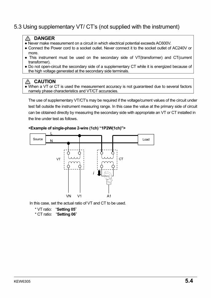
5.3 Using supplementary VT/ CT’s (not supplied with the instrument)
DANGER Never make measurement on a circuit in which electrical potential exceeds AC600V. Connect the Power cord to a socket outlet. Never connect it to the socket outlet of AC240V or
more. This instrument must be used on the secondary side of VT(transformer) and CT(current
transformer). Do not open-circuit the secondary side of a supplementary CT while it is energized because of
the high voltage generated at the secondary side terminals.
CAUTION When a VT or CT is used the measurement accuracy is not guaranteed due to several factors
namely phase characteristics and VT/CT accuracies.
The use of supplementary VT/CT’s may be required if the voltage/current values of the circuit under test fall outside the instrument measuring range. In this case the value at the primary side of circuit can be obtained directly by measuring the secondary side with appropriate an VT or CT installed in the line under test as follows. <Example of single-phase 2-wire (1ch) “1P2W(1ch)”>
In this case, set the actual ratio of VT and CT to be used. * VT ratio: “Setting 05” * CT ratio: “Setting 06”
VN V1 A1
N
L Source Load
VT CT
i
5.5 KEW6305
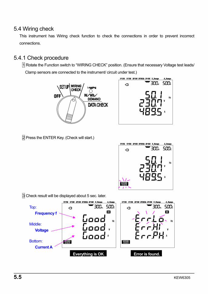
5.4 Wiring check This instrument has Wiring check function to check the connections in order to prevent incorrect
connections.
5.4.1 Check procedure 1 Rotate the Function switch to “WIRING CHECK” position. (Ensure that necessary Voltage test leads/
Clamp sensors are connected to the instrument/ circuit under test.)
2 Press the ENTER Key. (Check will start.)
3 Check result will be displayed about 5 sec. later.
_ Everything is OK._ _ Error is found._
Top: Frequency f
Middle: Voltage
Bottom: Current A
KEW6305 5.6
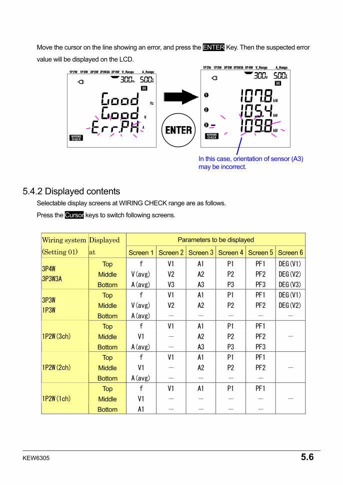
Move the cursor on the line showing an error, and press the ENTER Key. Then the suspected error
value will be displayed on the LCD.
5.4.2 Displayed contents Selectable display screens at WIRING CHECK range are as follows.
Press the Cursor keys to switch following screens.
Parameters to be displayed Wiring system (Setting 01)
Displayed at Screen 1 Screen 2 Screen 3 Screen 4 Screen 5 Screen 6
Top f V1 A1 P1 PF1 DEG(V1)
Middle V(avg) V2 A2 P2 PF2 DEG(V2) 3P4W
3P3W3A Bottom A(avg) V3 A3 P3 PF3 DEG(V3)
Top f V1 A1 P1 PF1 DEG(V1)
Middle V(avg) V2 A2 P2 PF2 DEG(V2) 3P3W
1P3W Bottom A(avg) - - - - -
Top f V1 A1 P1 PF1
Middle V1 - A2 P2 PF2 1P2W(3ch)
Bottom A(avg) - A3 P3 PF3
-
Top f V1 A1 P1 PF1
Middle V1 - A2 P2 PF2 1P2W(2ch)
Bottom A(avg) - - - -
-
Top f V1 A1 P1 PF1
Middle V1 - - - - 1P2W(1ch)
Bottom A1 - - - -
-
In this case, orientation of sensor (A3) may be incorrect.
5.7 KEW6305
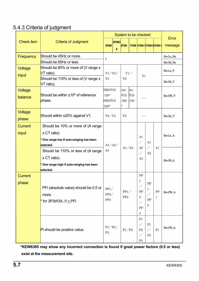
5.4.3 Criteria of judgment System to be checked
Check item Criteria of Judgment 3P4W
3P3W3
A 3P3W 1P3W 1P2W-31P2W-21P2W-1
Error
message
Should be 45Hz or more. Err.Lo_Hz Frequency Should be 65Hz or less.
f Err.Hi_Hz
Should be 60% or more of (V range x VT ratio). Err.Lo_V
Voltage
input Should be 110% or less of (V range x VT ratio).
V1/V2/V3
V1/V2
V1
Err.Hi_V
Voltage
balance Should be within ±10º of reference phase.
DEG(V2) :120° DEG(V3) :240°
DEG
(V2):300°
DEG
(V2):180
---- Err.PH_V
Voltage
phase Should within ±20% against V1. V2/V3 V2 ---- Err.bL_V
Should be 10% or more of (A range
x CT ratio).
* One range low if auto-ranging has been
selected.
Err.Lo_A
Current
input
Should be 110% or less of (A range
x CT ratio).
* One range high if auto-ranging has been
selected.
A1/A2/A3
A1/A2
A1/
A2/
A3
A1 /
A2 A1
Err.Hi_A
PFi (absolute value) should be 0.5 or
more.
* for 3P3W3A, 0 < PFi
PF1/PF2/PF3
PF1/PF2
PF1 /
PF2 /
PF3
PF1 /
PF2
PF1
Err.PH_A
Current
phase
Pi should be positive value. P1/P2/P3
P1/P2
P1/
P2/
P3
P1 /
P2 P1
Err.PH_A
*KEW6305 may show any incorrect connection is found if great power factors (0.5 or less)
exist at the measurement site.
KEW6305 5.8
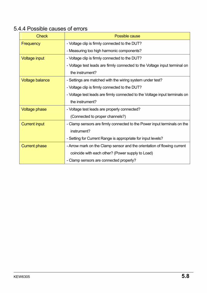
5.4.4 Possible causes of errors Check Possible cause
Frequency - Voltage clip is firmly connected to the DUT?
- Measuring too high harmonic components?
Voltage input - Voltage clip is firmly connected to the DUT?
- Voltage test leads are firmly connected to the Voltage input terminal on
the instrument?
Voltage balance - Settings are matched with the wiring system under test?
- Voltage clip is firmly connected to the DUT?
- Voltage test leads are firmly connected to the Voltage input terminals on
the instrument?
Voltage phase - Voltage test leads are properly connected?
(Connected to proper channels?)
Current input - Clamp sensors are firmly connected to the Power input terminals on the
instrument?
- Setting for Current Range is appropriate for input levels?
Current phase - Arrow mark on the Clamp sensor and the orientation of flowing current
coincide with each other? (Power supply to Load)
- Clamp sensors are connected properly?
6.1 KEW6305
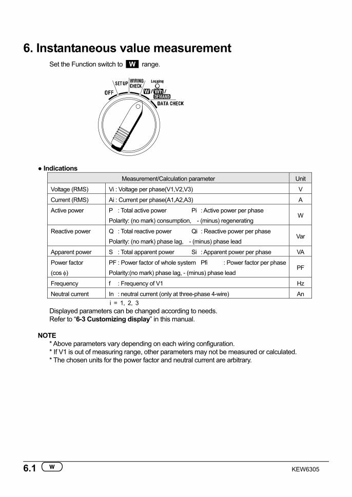
6. Instantaneous value measurement Set the Function switch to W range.
Indications Measurement/Calculation parameter Unit
Voltage (RMS) Vi : Voltage per phase(V1,V2,V3) V
Current (RMS) Ai : Current per phase(A1,A2,A3) A
Active power P : Total active power Pi : Active power per phase
Polarity: (no mark) consumption, - (minus) regenerating W
Reactive power Q : Total reactive power Qi : Reactive power per phase
Polarity: (no mark) phase lag, - (minus) phase lead Var
Apparent power S : Total apparent power Si : Apparent power per phase VA
Power factor
(cos φ)
PF : Power factor of whole system Pfi : Power factor per phase
Polarity:(no mark) phase lag, - (minus) phase lead PF
Frequency f : Frequency of V1 Hz
Neutral current In : neutral current (only at three-phase 4-wire) An i = 1, 2, 3
Displayed parameters can be changed according to needs. Refer to “6-3 Customizing display” in this manual.
NOTE
* Above parameters vary depending on each wiring configuration. * If V1 is out of measuring range, other parameters may not be measured or calculated. * The chosen units for the power factor and neutral current are arbitrary.
KEW6305 6.2
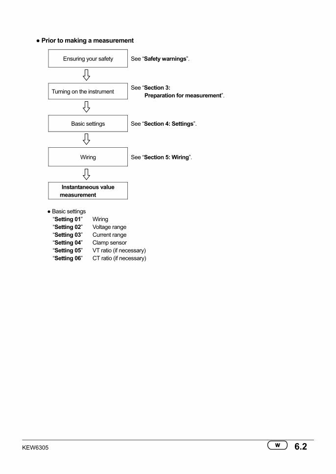
Prior to making a measurement
Ensuring your safety See “Safety warnings”.
Turning on the instrument See “Section 3:
Preparation for measurement”.
Basic settings See “Section 4: Settings”.
Wiring See “Section 5: Wiring”.
Instantaneous value measurement
Basic settings
“Setting 01” Wiring “Setting 02” Voltage range “Setting 03” Current range “Setting 04” Clamp sensor “Setting 05” VT ratio (if necessary) “Setting 06” CT ratio (if necessary)
6.3 KEW6305
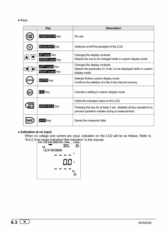
Keys
Key Description
START/STOP key No use
BACKLIGHT key Switches on/off the backlight of the LCD.
UP cursor key
DOWN cursor key Changes the display contents. Selects the row to be changed while in custom display mode.
LEFT cursor key
RIGHT cursor key
Changes the display contents. Selects the parameter (V, A etc.) to be displayed while in custom display mode
ENTER key
Selects/ Enters custom display mode. Confirms the deletion of a file in the internal memory.
ESC key Cancels a setting in custom display mode.
Holds the indicated value on the LCD.
DATA HOLD key Pressing this key for at least 2 sec. disables all key operations to prevent operation mistake during a measurement.
SAVE key Saves the measured data.
Indication at no input
When no voltage and current are input, indication on the LCD will be as follows. Refer to “6-5-2 Over-range indication/ Bar indication” in this manual.
KEW6305 6.4
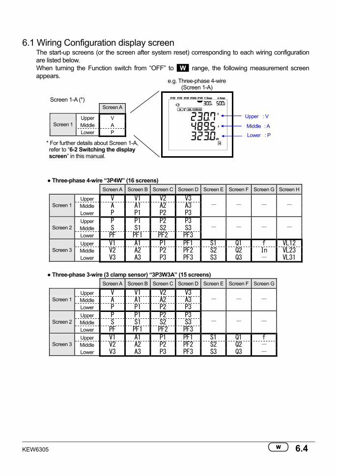
* For further details about Screen 1-A, refer to “6-2 Switching the display screen” in this manual.
6.1 Wiring Configuration display screen
The start-up screens (or the screen after system reset) corresponding to each wiring configuration are listed below. When turning the Function switch from “OFF” to W range, the following measurement screen appears.
Screen 1-A (*) Screen A
Upper V Middle A Screen 1 Lower P
Three-phase 4-wire “3P4W” (16 screens) Screen A Screen B Screen C Screen D Screen E Screen F Screen G Screen H
Upper V V1 V2 V3 Middle A A1 A2 A3 Screen 1 Lower P P1 P2 P3
- - - -
Upper P P1 P2 P3 Middle S S1 S2 S3 Screen 2 Lower PF PF1 PF2 PF3
- - - -
Upper V1 A1 P1 PF1 S1 Q1 f VL12 Middle V2 A2 P2 PF2 S2 Q2 In VL23 Screen 3 Lower V3 A3 P3 PF3 S3 Q3 - VL31
Three-phase 3-wire (3 clamp sensor) “3P3W3A” (15 screens)
Screen A Screen B Screen C Screen D Screen E Screen F Screen G
Upper V V1 V2 V3 Middle A A1 A2 A3 Screen 1 Lower P P1 P2 P3
- - -
Upper P P1 P2 P3 Middle S S1 S2 S3 Screen 2 Lower PF PF1 PF2 PF3
- - -
Upper V1 A1 P1 PF1 S1 Q1 f Middle V2 A2 P2 PF2 S2 Q2 - Screen 3 Lower V3 A3 P3 PF3 S3 Q3 -
Upper : V
Middle : A
Lower : P
e.g. Three-phase 4-wire(Screen 1-A)
6.5 KEW6305
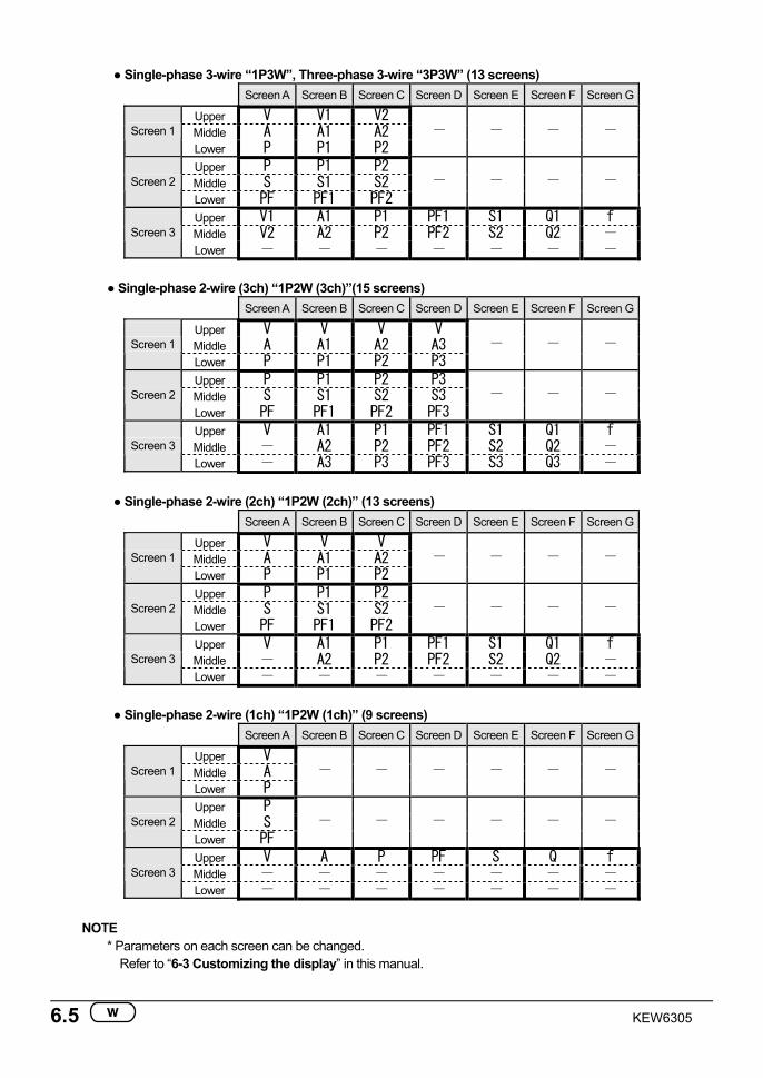
Single-phase 3-wire “1P3W”, Three-phase 3-wire “3P3W” (13 screens) Screen A Screen B Screen C Screen D Screen E Screen F Screen G
Upper V V1 V2 Middle A A1 A2 Screen 1 Lower P P1 P2
- - - -
Upper P P1 P2 Middle S S1 S2 Screen 2 Lower PF PF1 PF2
- - - -
Upper V1 A1 P1 PF1 S1 Q1 f Middle V2 A2 P2 PF2 S2 Q2 - Screen 3 Lower - - - - - - -
Single-phase 2-wire (3ch) “1P2W (3ch)”(15 screens)
Screen A Screen B Screen C Screen D Screen E Screen F Screen G
Upper V V V V Middle A A1 A2 A3 Screen 1 Lower P P1 P2 P3
- - -
Upper P P1 P2 P3 Middle S S1 S2 S3 Screen 2 Lower PF PF1 PF2 PF3
- - -
Upper V A1 P1 PF1 S1 Q1 f Middle - A2 P2 PF2 S2 Q2 - Screen 3 Lower - A3 P3 PF3 S3 Q3 -
Single-phase 2-wire (2ch) “1P2W (2ch)” (13 screens)
Screen A Screen B Screen C Screen D Screen E Screen F Screen G
Upper V V V Middle A A1 A2 Screen 1 Lower P P1 P2
- - - -
Upper P P1 P2 Middle S S1 S2 Screen 2 Lower PF PF1 PF2
- - - -
Upper V A1 P1 PF1 S1 Q1 f Middle - A2 P2 PF2 S2 Q2 - Screen 3 Lower - - - - - - -
Single-phase 2-wire (1ch) “1P2W (1ch)” (9 screens)
Screen A Screen B Screen C Screen D Screen E Screen F Screen G
Upper V Middle A Screen 1 Lower P
- - - - - -
Upper P Middle S Screen 2 Lower PF
- - - - - -
Upper V A P PF S Q f Middle - - - - - - - Screen 3 Lower - - - - - - -
NOTE
* Parameters on each screen can be changed. Refer to “6-3 Customizing the display” in this manual.
KEW6305 6.6
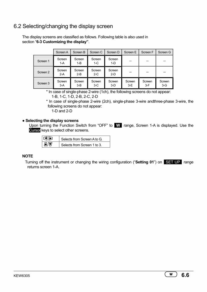
6.2 Selecting/changing the display screen
The display screens are classified as follows. Following table is also used in section “6-3 Customizing the display”.
Screen A Screen B Screen C Screen D Screen E Screen F Screen G
Screen 1 Screen 1-A
Screen 1-B
Screen 1-C
Screen 1-D - - -
Screen 2 Screen 2-A
Screen 2-B
Screen 2-C
Screen 2-D - - -
Screen 3 Screen 3-A
Screen 3-B
Screen 3-C
Screen 3-D
Screen 3-E
Screen 3-F
Screen 3-G
* In case of single-phase 2-wire (1ch), the following screens do not appear: 1-B, 1-C, 1-D, 2-B, 2-C, 2-D
* In case of single-phase 2-wire (2ch), single-phase 3-wire andthree-phase 3-wire, the following screens do not appear:
1-D and 2-D
Selecting the display screens Upon turning the Function Switch from “OFF” to W range, Screen 1-A is displayed. Use the Cursor keys to select other screens.
Selects from Screen A to G. Selects from Screen 1 to 3.
NOTE
Turning off the instrument or changing the wiring configuration (“Setting 01”) on SET UP range returns screen 1-A.
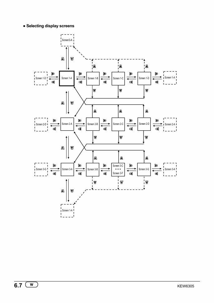
6.7 KEW6305
Selecting display screens
Screen 1-B Screen 1-C Screen 1-D
Screen 2-B Screen 2-C Screen 2-D
Screen 3-B Screen 3-C
• • •Screen 3-F
Screen 3-G
Screen 1-A
Screen 2-A
Screen 3-A
Screen 1-A
Screen3-A
Screen 1-A
Screen 2-D
Screen 3-G
Screen 2-A
Screen 3-A
Screen 1-D
KEW6305 6.8
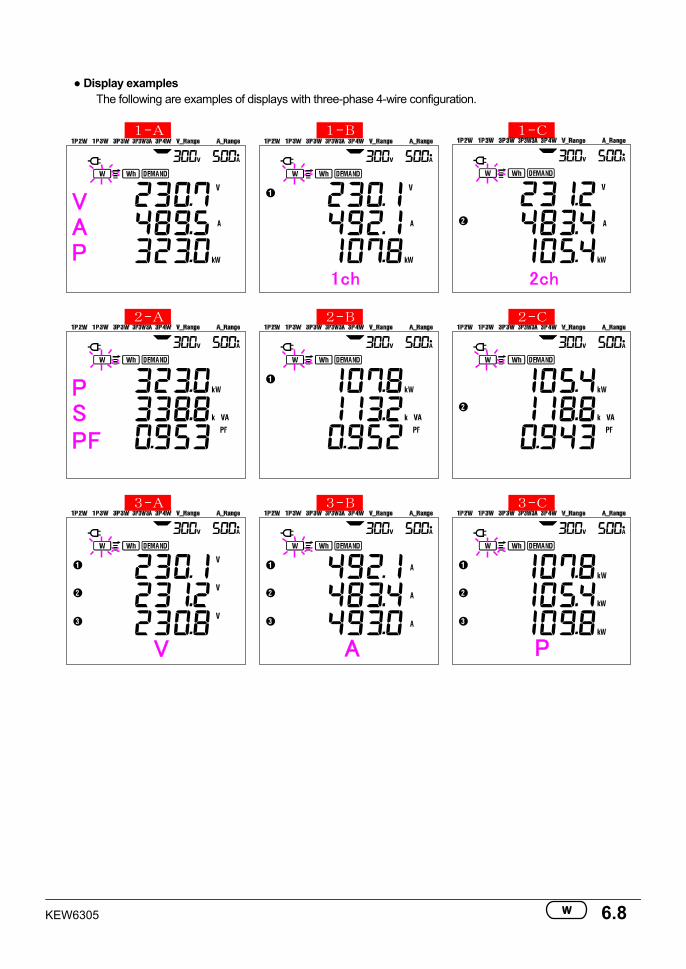
Display examples
The following are examples of displays with three-phase 4-wire configuration. _1-A_ _1-B_ _1-C_
AV
P
1ch
2ch
_2-A_ _2-B_ _2-C_
SP
PF
_3-A_ _3-B_ _3-C_
V
A
P
6.9 KEW6305
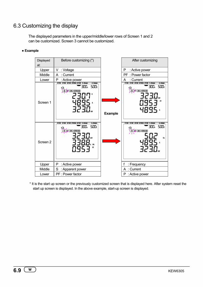
6.3 Customizing the display The displayed parameters in the upper/middle/lower rows of Screen 1 and 2 can be customized. Screen 3 cannot be customized.
Example
Displayed at:
Before customizing (*) After customizing
Upper V : Voltage P : Active power Middle A : Current PF : Power factor Lower P : Active power A : Current
Screen 1
Example
Screen 2
Upper P : Active power f : Frequency Middle S : Apparent power A : Current Lower PF : Power factor P : Active power
* It is the start up screen or the previously customized screen that is displayed here. After system reset the
start up screen is displayed. In the above example, start-up screen is displayed.
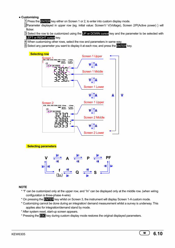
KEW6305 6.10
Customizing 1 Press the ENTER key either on Screen 1 or 2, to enter into custom display mode. 2Parameter displayed in upper row eg. initial value: Screen1/ V(Voltage), Screen 2/P(Active power) will flicker.
3 Select the row to be customized using the UP or DOWN cursor key and the parameter to be selected with LEFT or RIGHT cursor key.
4 When customizing other rows, select the row and parameters in same way. 5 Select any parameter you want to display it at each row, and press the ENTER key.
Selecting row
Screen 1 1
Screen 2
Selecting parameters
NOTE * “f” can be customized only at the upper row, and “In” can be displayed only at the middle row. (when wiring
configuration is three-phase 4-wire) * On pressing the ENTER key whilst on Screen 3, the instrument will display Screen 1-A custom mode. * Customizing cannot be done during an integration/ demand measurement whilst a survey is underway. This
applies also for integration/demand stand by mode. * After system reset, start-up screen appears. * Pressing the ESC key during custom display mode restores the original displayed parameters.
V A P PF
SQ f (In)
Screen 1 Middle
Screen 1 Upper
Screen 1 Lower
Screen 2 Middle
Screen 1 Upper
Screen 2 Lower
6.11 KEW6305
File No.
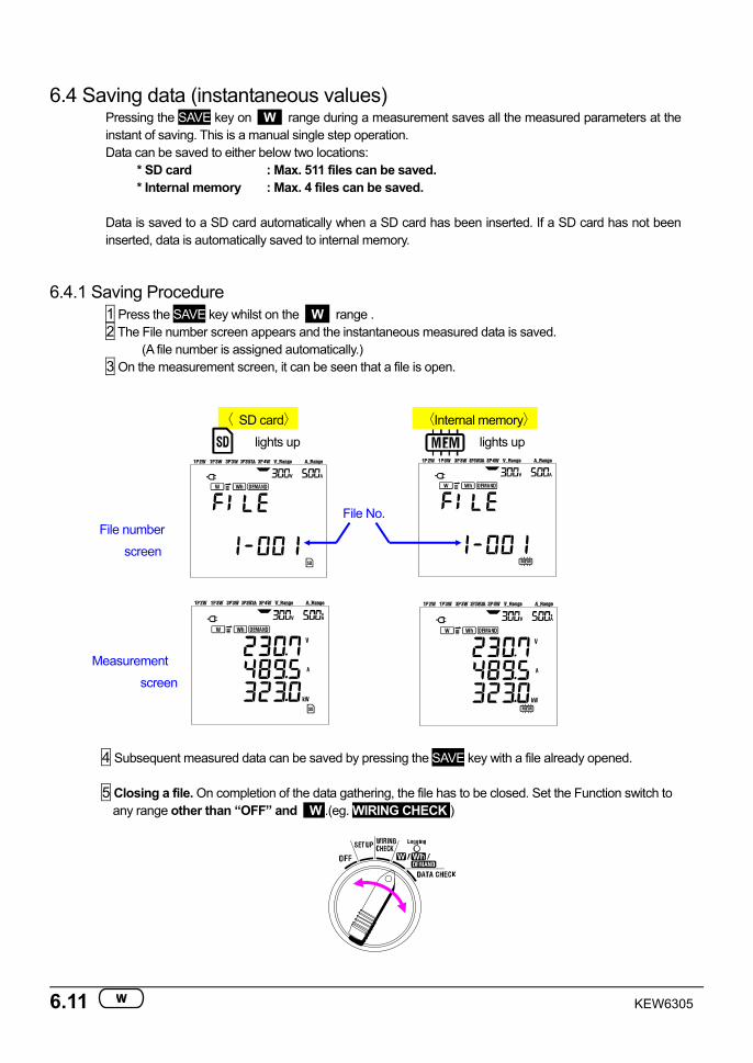
6.4 Saving data (instantaneous values) Pressing the SAVE key on W range during a measurement saves all the measured parameters at the instant of saving. This is a manual single step operation. Data can be saved to either below two locations:
* SD card : Max. 511 files can be saved. * Internal memory : Max. 4 files can be saved.
Data is saved to a SD card automatically when a SD card has been inserted. If a SD card has not been inserted, data is automatically saved to internal memory.
6.4.1 Saving Procedure 1 Press the SAVE key whilst on the W range . 2 The File number screen appears and the instantaneous measured data is saved.
(A file number is assigned automatically.) 3 On the measurement screen, it can be seen that a file is open.
〈 SD card〉
lights up
〈Internal memory〉
lights up
File number
screen
Measurement
screen
4 Subsequent measured data can be saved by pressing the SAVE key with a file already opened.
5 Closing a file. On completion of the data gathering, the file has to be closed. Set the Function switch to any range other than “OFF” and W .(eg. WIRING CHECK )
KEW6305 6.12
Each time the SAVE key is pressed; the measured data is saved in the same file. To save the data into an other file (only when SD card is used), press the SAVEkey again on W range. Then repeat the saving procedure.
NOTE
* When the Function switch is set to OFF position before closing a file, the file remains open and is not saved. Be sure to set it to any position other than OFF and W , thus closing the file.
* If the SAVE key is pressed continuously (2 times or more in 1sec.), the measured data may not be saved correctly.
* The file number becomes “001” when; (1) the file number has exceeded 999 (2) after system reset
* If the same file no. exists, the old one will be overwritten.
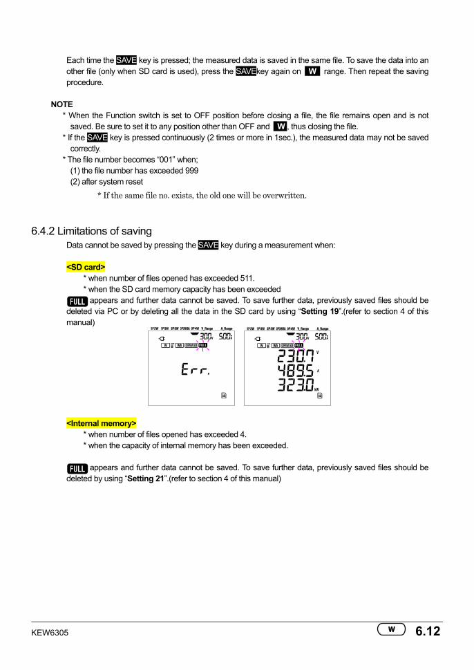
6.4.2 Limitations of saving Data cannot be saved by pressing the SAVE key during a measurement when:
<SD card>
* when number of files opened has exceeded 511. * when the SD card memory capacity has been exceeded
appears and further data cannot be saved. To save further data, previously saved files should be deleted via PC or by deleting all the data in the SD card by using “Setting 19”.(refer to section 4 of this manual)
<Internal memory> * when number of files opened has exceeded 4. * when the capacity of internal memory has been exceeded.
appears and further data cannot be saved. To save further data, previously saved files should be deleted by using “Setting 21”.(refer to section 4 of this manual)
6.13 KEW6305
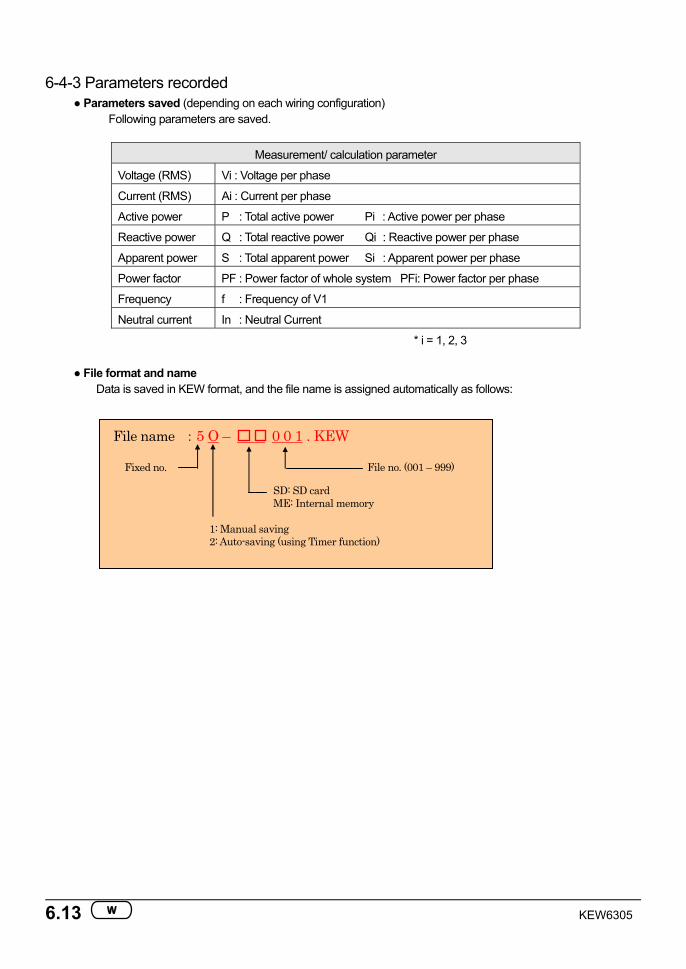
6-4-3 Parameters recorded Parameters saved (depending on each wiring configuration)
Following parameters are saved.
Measurement/ calculation parameter
Voltage (RMS) Vi : Voltage per phase
Current (RMS) Ai : Current per phase
Active power P : Total active power Pi : Active power per phase
Reactive power Q : Total reactive power Qi : Reactive power per phase
Apparent power S : Total apparent power Si : Apparent power per phase
Power factor PF : Power factor of whole system PFi: Power factor per phase
Frequency f : Frequency of V1
Neutral current In : Neutral Current
* i = 1, 2, 3
File format and name Data is saved in KEW format, and the file name is assigned automatically as follows:
File name :5 O – 0 0 1 . KEW
1: Manual saving 2: Auto-saving (using Timer function)
Fixed no.
SD: SD card ME: Internal memory
File no. (001 – 999)
KEW6305 6.14
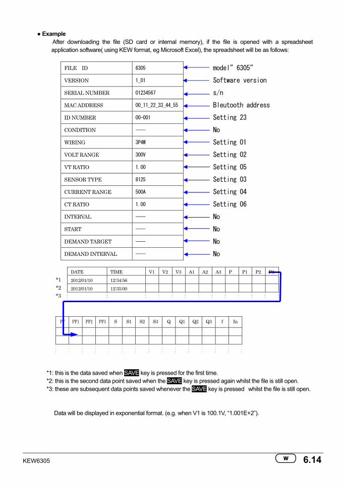
Example After downloading the file (SD card or internal memory), if the file is opened with a spreadsheet application software( using KEW format, eg Microsoft Excel), the spreadsheet will be as follows:
FILE ID 6305 model”6305”
VERSION 1_01 Software version
SERIAL NUMBER 01234567 s/n
MAC ADDRESS 00_11_22_33_44_55 Bleutooth address
ID NUMBER 00-001 Setting 23
CONDITION ---- No
WIRING 3P4W Setting 01
VOLT RANGE 300V Setting 02
VT RATIO 1.00 Setting 05
SENSOR TYPE 8125 Setting 03
CURRENT RANGE 500A Setting 04
CT RATIO 1.00 Setting 06
INTERVAL ---- No
START ---- No
DEMAND TARGET ---- No
DEMAND INTERVAL ---- No
DATE TIME V1 V2 V3 A1 A2 A3 P P1 P2 P3 2012/01/10 12:34:56 2012/01/10 12:35:00
PF PF1 PF2 PF3 S S1 S2 S3 Q Q1 Q2 Q3 f In
*1: this is the data saved when SAVE key is pressed for the first time. *2: this is the second data point saved when the SAVE key is pressed again whilst the file is still open. *3: these are subsequent data points saved whenever the SAVE key is pressed whilst the file is still open.
Data will be displayed in exponential format. (e.g. when V1 is 100.1V, “1.001E+2”).
*1 *2 *3
6.15 KEW6305
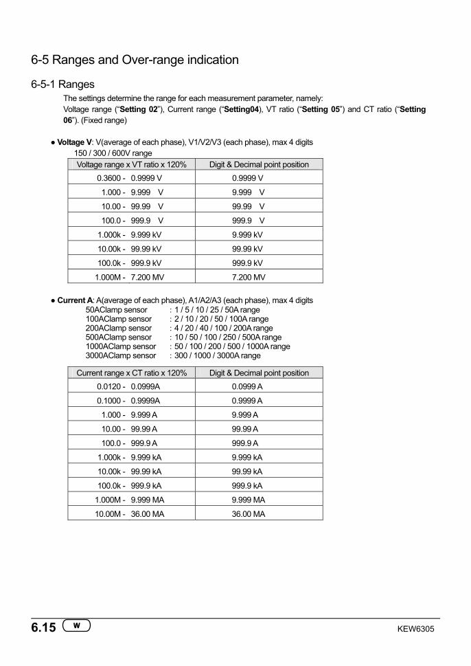
6-5 Ranges and Over-range indication
6-5-1 Ranges The settings determine the range for each measurement parameter, namely: Voltage range (“Setting 02”), Current range (“Setting04), VT ratio (“Setting 05”) and CT ratio (“Setting 06”). (Fixed range)
Voltage V: V(average of each phase), V1/V2/V3 (each phase), max 4 digits
150 / 300 / 600V range Voltage range x VT ratio x 120% Digit & Decimal point position
0.3600 - 0.9999 V 0.9999 V
1.000 - 9.999 V 9.999 V
10.00 - 99.99 V 99.99 V
100.0 - 999.9 V 999.9 V
1.000k - 9.999 kV 9.999 kV
10.00k - 99.99 kV 99.99 kV
100.0k - 999.9 kV 999.9 kV
1.000M - 7.200 MV 7.200 MV
Current A: A(average of each phase), A1/A2/A3 (each phase), max 4 digits 50AClamp sensor :1 / 5 / 10 / 25 / 50A range 100AClamp sensor :2 / 10 / 20 / 50 / 100A range 200AClamp sensor :4 / 20 / 40 / 100 / 200A range 500AClamp sensor :10 / 50 / 100 / 250 / 500A range 1000AClamp sensor :50 / 100 / 200 / 500 / 1000A range 3000AClamp sensor :300 / 1000 / 3000A range
Current range x CT ratio x 120% Digit & Decimal point position 0.0120 - 0.0999A 0.0999 A
0.1000 - 0.9999A 0.9999 A
1.000 - 9.999 A 9.999 A
10.00 - 99.99 A 99.99 A
100.0 - 999.9 A 999.9 A
1.000k - 9.999 kA 9.999 kA
10.00k - 99.99 kA 99.99 kA
100.0k - 999.9 kA 999.9 kA
1.000M - 9.999 MA 9.999 MA
10.00M - 36.00 MA 36.00 MA
KEW6305 6.16
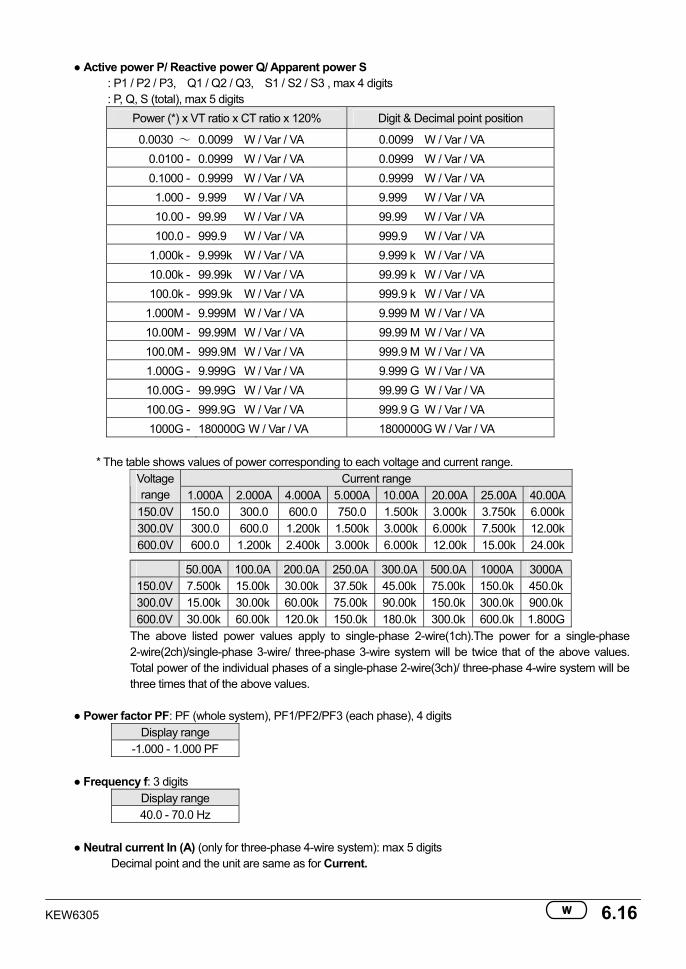
Active power P/ Reactive power Q/ Apparent power S : P1 / P2 / P3, Q1 / Q2 / Q3, S1 / S2 / S3 , max 4 digits : P, Q, S (total), max 5 digits
Power (*) x VT ratio x CT ratio x 120% Digit & Decimal point position
0.0030 ~ 0.0099 W / Var / VA 0.0099 W / Var / VA 0.0100 - 0.0999 W / Var / VA 0.0999 W / Var / VA 0.1000 - 0.9999 W / Var / VA 0.9999 W / Var / VA 1.000 - 9.999 W / Var / VA 9.999 W / Var / VA 10.00 - 99.99 W / Var / VA 99.99 W / Var / VA 100.0 - 999.9 W / Var / VA 999.9 W / Var / VA
1.000k - 9.999k W / Var / VA 9.999 k W / Var / VA 10.00k - 99.99k W / Var / VA 99.99 k W / Var / VA 100.0k - 999.9k W / Var / VA 999.9 k W / Var / VA
1.000M - 9.999M W / Var / VA 9.999 M W / Var / VA 10.00M - 99.99M W / Var / VA 99.99 M W / Var / VA 100.0M - 999.9M W / Var / VA 999.9 M W / Var / VA 1.000G - 9.999G W / Var / VA 9.999 G W / Var / VA 10.00G - 99.99G W / Var / VA 99.99 G W / Var / VA 100.0G - 999.9G W / Var / VA 999.9 G W / Var / VA 1000G - 180000G W / Var / VA 1800000G W / Var / VA
* The table shows values of power corresponding to each voltage and current range.
Current range Voltage range 1.000A 2.000A 4.000A 5.000A 10.00A 20.00A 25.00A 40.00A
150.0V 150.0 300.0 600.0 750.0 1.500k 3.000k 3.750k 6.000k 300.0V 300.0 600.0 1.200k 1.500k 3.000k 6.000k 7.500k 12.00k 600.0V 600.0 1.200k 2.400k 3.000k 6.000k 12.00k 15.00k 24.00k
50.00A 100.0A 200.0A 250.0A 300.0A 500.0A 1000A 3000A
150.0V 7.500k 15.00k 30.00k 37.50k 45.00k 75.00k 150.0k 450.0k 300.0V 15.00k 30.00k 60.00k 75.00k 90.00k 150.0k 300.0k 900.0k 600.0V 30.00k 60.00k 120.0k 150.0k 180.0k 300.0k 600.0k 1.800G
The above listed power values apply to single-phase 2-wire(1ch).The power for a single-phase 2-wire(2ch)/single-phase 3-wire/ three-phase 3-wire system will be twice that of the above values. Total power of the individual phases of a single-phase 2-wire(3ch)/ three-phase 4-wire system will be three times that of the above values.
Power factor PF: PF (whole system), PF1/PF2/PF3 (each phase), 4 digits
Display range -1.000 - 1.000 PF
Frequency f: 3 digits
Display range 40.0 - 70.0 Hz
Neutral current In (A) (only for three-phase 4-wire system): max 5 digits
Decimal point and the unit are same as for Current.
6.17 KEW6305
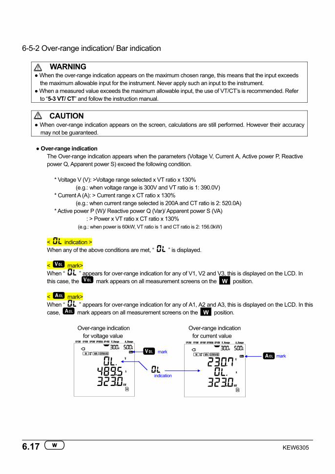
6-5-2 Over-range indication/ Bar indication
WARNING When the over-range indication appears on the maximum chosen range, this means that the input exceeds
the maximum allowable input for the instrument. Never apply such an input to the instrument. When a measured value exceeds the maximum allowable input, the use of VT/CT’s is recommended. Refer
to “5-3 VT/ CT” and follow the instruction manual.
CAUTION When over-range indication appears on the screen, calculations are still performed. However their accuracy
may not be guaranteed.
Over-range indication The Over-range indication appears when the parameters (Voltage V, Current A, Active power P, Reactive power Q, Apparent power S) exceed the following condition.
* Voltage V (V): >Voltage range selected x VT ratio x 130%
(e.g.: when voltage range is 300V and VT ratio is 1: 390.0V) * Current A (A): > Current range x CT ratio x 130%
(e.g.: when current range selected is 200A and CT ratio is 2: 520.0A) * Active power P (W)/ Reactive power Q (Var)/ Apparent power S (VA) : > Power x VT ratio x CT ratio x 130%
(e.g.: when power is 60kW, VT ratio is 1 and CT ratio is 2: 156.0kW)
< indication > When any of the above conditions are met, “ ” is displayed.
< mark> When “ ” appears for over-range indication for any of V1, V2 and V3, this is displayed on the LCD. In this case, the mark appears on all measurement screens on the W position.
< mark> When “ ” appears for over-range indication for any of A1, A2 and A3, this is displayed on the LCD. In this case, mark appears on all measurement screens on the W position.
Over-range indication Over-range indication
for voltage value for current value
indication
mark mark
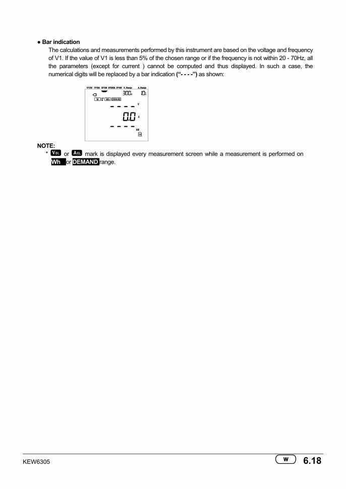
KEW6305 6.18
Bar indication
The calculations and measurements performed by this instrument are based on the voltage and frequency of V1. If the value of V1 is less than 5% of the chosen range or if the frequency is not within 20 - 70Hz, all the parameters (except for current ) cannot be computed and thus displayed. In such a case, the numerical digits will be replaced by a bar indication (“- - - -”) as shown:
NOTE:
* or mark is displayed every measurement screen while a measurement is performed on Wh or DEMAND range.
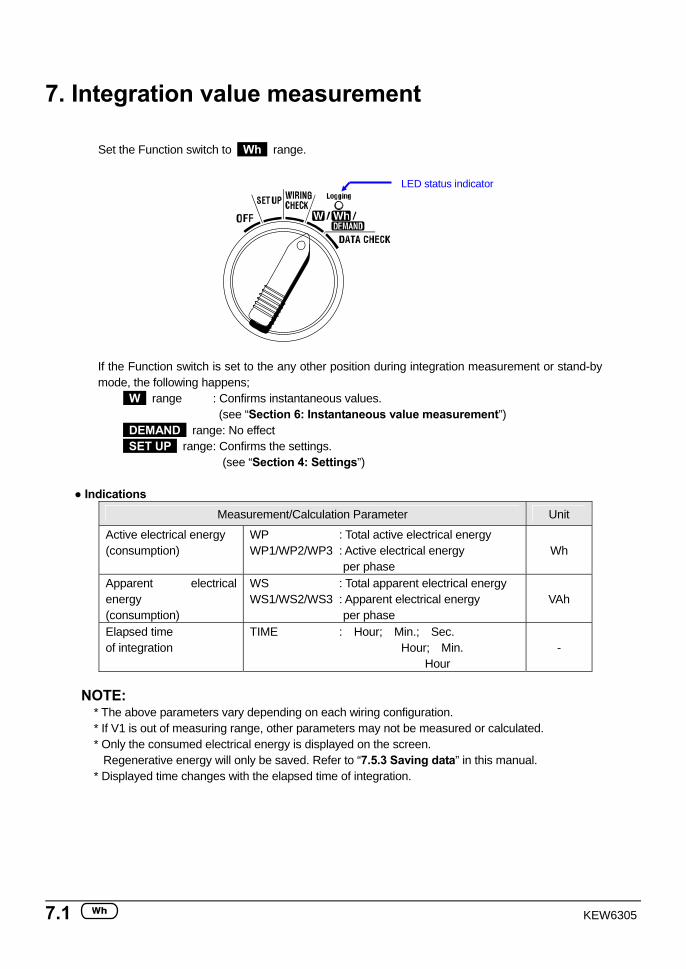
7.1 KEW6305
LED status indicator
7. Integration value measurement
Set the Function switch to Wh range.
If the Function switch is set to the any other position during integration measurement or stand-by mode, the following happens;
W range : Confirms instantaneous values. (see “Section 6: Instantaneous value measurement”) DEMAND range: No effect SET UP range : Confirms the settings.
(see “Section 4: Settings”)
Indications Measurement/Calculation Parameter Unit
Active electrical energy (consumption)
WP : Total active electrical energy WP1/WP2/WP3 : Active electrical energy
per phase Wh
Apparent electrical energy (consumption)
WS : Total apparent electrical energy WS1/WS2/WS3 : Apparent electrical energy
per phase VAh
Elapsed time of integration
TIME : Hour; Min.; Sec. Hour; Min.
Hour -
NOTE:
* The above parameters vary depending on each wiring configuration. * If V1 is out of measuring range, other parameters may not be measured or calculated. * Only the consumed electrical energy is displayed on the screen. Regenerative energy will only be saved. Refer to “7.5.3 Saving data” in this manual. * Displayed time changes with the elapsed time of integration.
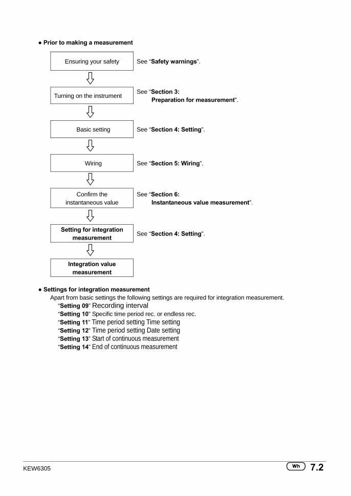
KEW6305 7.2
Prior to making a measurement
Ensuring your safety See “Safety warnings”.
Turning on the instrument See “Section 3:
Preparation for measurement”.
Basic setting See “Section 4: Setting”.
Wiring See “Section 5: Wiring”.
Confirm the instantaneous value
See “Section 6: Instantaneous value measurement”.
Setting for integration measurement See “Section 4: Setting”.
Integration value measurement
Settings for integration measurement
Apart from basic settings the following settings are required for integration measurement. “Setting 09” Recording interval “Setting 10” Specific time period rec. or endless rec. “Setting 11” Time period setting Time setting “Setting 12” Time period setting Date setting “Setting 13” Start of continuous measurement “Setting 14” End of continuous measurement
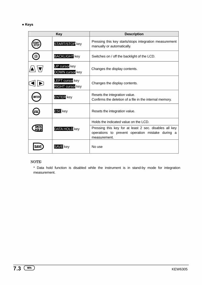
7.3 KEW6305
Keys
Key Description
START/STOP key
Pressing this key starts/stops integration measurement manually or automatically.
BACKLIGHT key Switches on / off the backlight of the LCD.
UP cursor key
DOWN cursor key Changes the display contents.
LEFT cursor key
RIGHT cursor key Changes the display contents.
ENTER key
Resets the integration value. Confirms the deletion of a file in the internal memory.
ESC key Resets the integration value.
Holds the indicated value on the LCD.
DATA HOLD key Pressing this key for at least 2 sec. disables all key operations to prevent operation mistake during a measurement.
SAVE key No use
NOTE:
* Data hold function is disabled while the instrument is in stand-by mode for integration measurement.
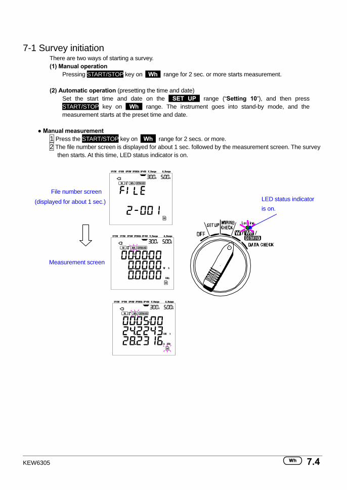
KEW6305 7.4
7-1 Survey initiation
There are two ways of starting a survey. (1) Manual operation
Pressing START/STOP key on Wh range for 2 sec. or more starts measurement.
(2) Automatic operation (presetting the time and date) Set the start time and date on the SET UP range (“Setting 10”), and then press START/STOP key on Wh range. The instrument goes into stand-by mode, and the measurement starts at the preset time and date.
Manual measurement 1 Press the START/STOP key on Wh range for 2 secs. or more. 2 The file number screen is displayed for about 1 sec. followed by the measurement screen. The survey
then starts. At this time, LED status indicator is on.
File number screen
(displayed for about 1 sec.)
Measurement screen
LED status indicator is on.
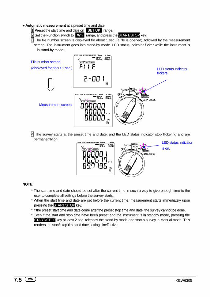
7.5 KEW6305
Automatic measurement at a preset time and date
1 Preset the start time and date on SET UP range. 2 Set the Function switch to Wh range, and press the START/STOP key. 3 The file number screen is displayed for about 1 sec. (a file is opened), followed by the measurement
screen. The instrument goes into stand-by mode. LED status indicator flicker while the instrument is in stand-by mode.
File number screen
(displayed for about 1 sec.)
Measurement screen
4 The survey starts at the preset time and date, and the LED status indicator stop flickering and are permanently on.
NOTE: * The start time and date should be set after the current time in such a way to give enough time to the
user to complete all settings before the survey starts. * When the start time and date are set before the current time, measurement starts immediately upon
pressing the START/STOP key. * If the preset start time and date come after the preset stop time and date, the survey cannot be done. * Even if the start and stop time have been preset and the instrument is in standby mode, pressing the
START/STOP key at least 2 sec. releases the stand-by mode and start a survey in Manual mode. This renders the start/ stop time and date settings ineffective.
LED status indicator flickers
LED status indicator is on.
KEW6305 7.6
7.2 Survey closure
There are two ways of closing a survey. (1) Manual operation
Pressing START/STOP key on Wh range for 2 sec. or more closes the survey. This action also closes a survey started automatically at a preset time and date. LED status indicator goes off. The survey is then closed.
(2) Automatic operation (presetting the time and date)
This can be done by presetting the stop time and date on SET UP range. LED status indicator goes off. The survey is then closed.
NOTE
* A survey will be closed and lost when the instrument is switched off. * Manually starting a survey renders a preset stop time and date ineffective. The survey has to be closed
manually in this case. * If the survey duration is shorter than the integration interval (“Setting 09”) the measured data will not be
saved. * If the preset start time and date come after the preset stop time and date, the survey cannot be done. * Pressing the START/STOP key 2 sec. or more releases the stand-by mode.LED status indicator goes off.
7.3 Resetting the integration value
There are two methods for resetting the integration value and period from previous measurements.
a) Press ESC key on Wh range 2 sec. or more. b) System reset
NOTE * Integration value cannot be reset during a measurement or while the instrument is in stand-by mode.
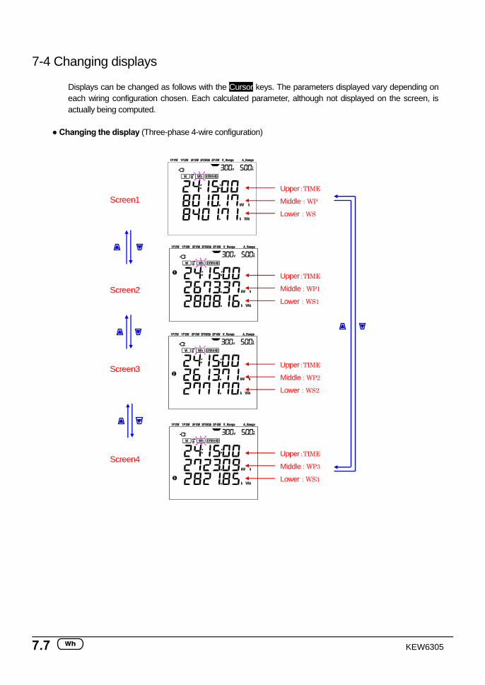
7.7 KEW6305
7-4 Changing displays Displays can be changed as follows with the Cursor keys. The parameters displayed vary depending on each wiring configuration chosen. Each calculated parameter, although not displayed on the screen, is actually being computed.
Changing the display (Three-phase 4-wire configuration)
Screen1
Screen2
Screen3
Screen4
Upper:TIME
Middle:WP
Lower:WS
Upper:TIME
Middle:WP1
Lower:WS1
Upper:TIME
Middle:WP2
Lower:WS2
Upper:TIME
Middle:WP3
Lower:WS3
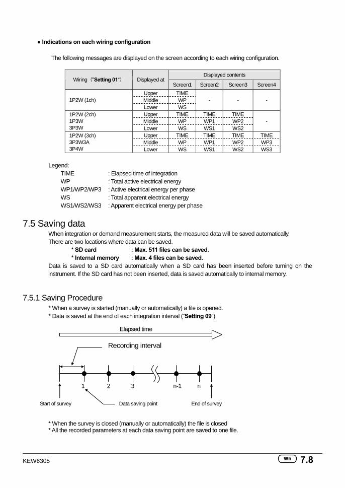
KEW6305 7.8
Indications on each wiring configuration
The following messages are displayed on the screen according to each wiring configuration.
Displayed contents
Wiring(“Setting 01”) Displayed at Screen1 Screen2 Screen3 Screen4
Upper TIME Middle WP 1P2W (1ch) Lower WS
- - -
Upper TIME TIME TIME Middle WP WP1 WP2
1P2W (2ch) 1P3W 3P3W Lower WS WS1 WS2
-
Upper TIME TIME TIME TIME Middle WP WP1 WP2 WP3
1P2W (3ch) 3P3W3A 3P4W Lower WS WS1 WS2 WS3
Legend:
TIME : Elapsed time of integration WP : Total active electrical energy WP1/WP2/WP3 : Active electrical energy per phase WS : Total apparent electrical energy WS1/WS2/WS3 : Apparent electrical energy per phase
7.5 Saving data When integration or demand measurement starts, the measured data will be saved automatically. There are two locations where data can be saved.
* SD card : Max. 511 files can be saved. * Internal memory : Max. 4 files can be saved.
Data is saved to a SD card automatically when a SD card has been inserted before turning on the instrument. If the SD card has not been inserted, data is saved automatically to internal memory.
7.5.1 Saving Procedure * When a survey is started (manually or automatically) a file is opened. * Data is saved at the end of each integration interval (“Setting 09”).
Elapsed time
Recording interval
1 2 3 n-1 n
Start of survey Data saving point End of survey
* When the survey is closed (manually or automatically) the file is closed * All the recorded parameters at each data saving point are saved to one file.
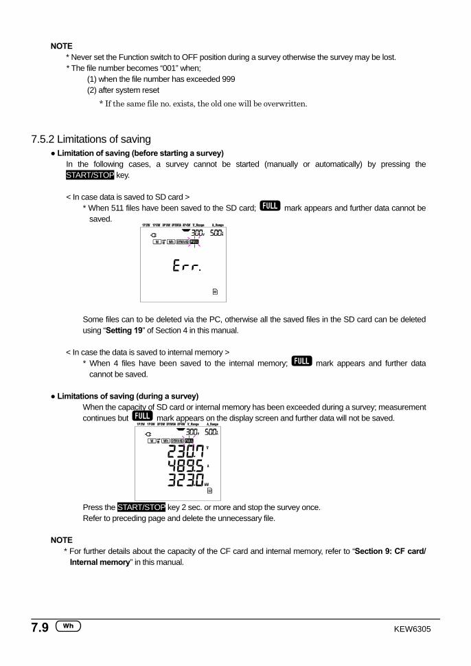
7.9 KEW6305
NOTE * Never set the Function switch to OFF position during a survey otherwise the survey may be lost. * The file number becomes “001” when;
(1) when the file number has exceeded 999 (2) after system reset
* If the same file no. exists, the old one will be overwritten.
7.5.2 Limitations of saving Limitation of saving (before starting a survey)
In the following cases, a survey cannot be started (manually or automatically) by pressing the START/STOP key.
< In case data is saved to SD card >
* When 511 files have been saved to the SD card; mark appears and further data cannot be saved.
Some files can to be deleted via the PC, otherwise all the saved files in the SD card can be deleted using “Setting 19” of Section 4 in this manual.
< In case the data is saved to internal memory >
* When 4 files have been saved to the internal memory; mark appears and further data cannot be saved.
Limitations of saving (during a survey)
When the capacity of SD card or internal memory has been exceeded during a survey; measurement continues but mark appears on the display screen and further data will not be saved.
Press the START/STOP key 2 sec. or more and stop the survey once. Refer to preceding page and delete the unnecessary file.
NOTE
* For further details about the capacity of the CF card and internal memory, refer to “Section 9: CF card/ Internal memory” in this manual.
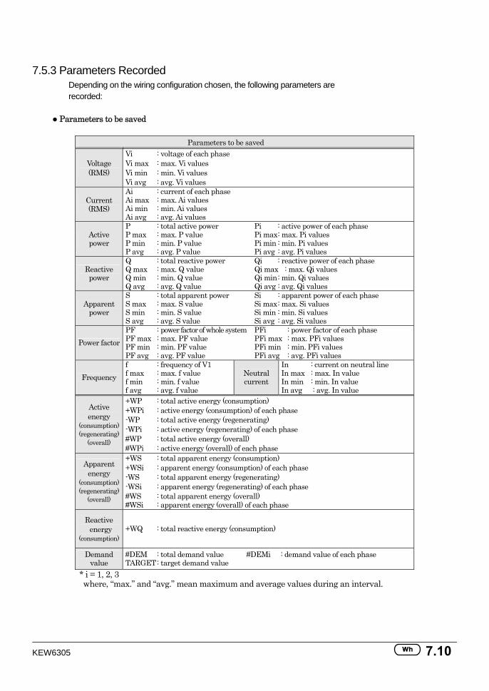
KEW6305 7.10
7.5.3 Parameters Recorded Depending on the wiring configuration chosen, the following parameters are recorded:
Parameters to be saved
Parameters to be saved
Voltage (RMS)
Vi : voltage of each phase Vi max : max. Vi values Vi min : min. Vi values Vi avg : avg. Vi values
Current (RMS)
Ai : current of each phase Ai max : max. Ai values Ai min : min. Ai values Ai avg : avg. Ai values
Active power
P : total active power Pi : active power of each phase P max : max. P value Pi max : max. Pi values P min : min. P value Pi min : min. Pi values P avg : avg. P value Pi avg : avg. Pi values
Reactive power
Q : total reactive power Qi : reactive power of each phase Q max : max. Q value Qi max : max. Qi values Q min : min. Q value Qi min : min. Qi values Q avg : avg. Q value Qi avg : avg. Qi values
Apparent power
S : total apparent power Si : apparent power of each phase S max : max. S value Si max : max. Si values S min : min. S value Si min : min. Si values S avg : avg. S value Si avg : avg. Si values
Power factor PF : power factor of whole system PFi : power factor of each phase PF max : max. PF value PFi max : max. PFi values PF min : min. PF value PFi min : min. PFi values PF avg : avg. PF value PFi avg : avg. PFi values
Frequency f : frequency of V1 f max : max. f value f min : min. f value f avg : avg. f value
Neutral current
In : current on neutral line In max : max. In value In min : min. In value In avg : avg. In value
Active energy
(consumption) (regenerating)
(overall)
+WP : total active energy (consumption) +WPi : active energy (consumption) of each phase -WP : total active energy (regenerating) -WPi : active energy (regenerating) of each phase #WP : total active energy (overall) #WPi : active energy (overall) of each phase
Apparent energy
(consumption) (regenerating)
(overall)
+WS : total apparent energy (consumption) +WSi : apparent energy (consumption) of each phase -WS : total apparent energy (regenerating) -WSi : apparent energy (regenerating) of each phase #WS : total apparent energy (overall) #WSi : apparent energy (overall) of each phase
Reactive energy
(consumption) +WQ : total reactive energy (consumption)
Demand value
#DEM : total demand value #DEMi : demand value of each phase TARGET : target demand value
* i = 1, 2, 3 where, “max.” and “avg.” mean maximum and average values during an interval.
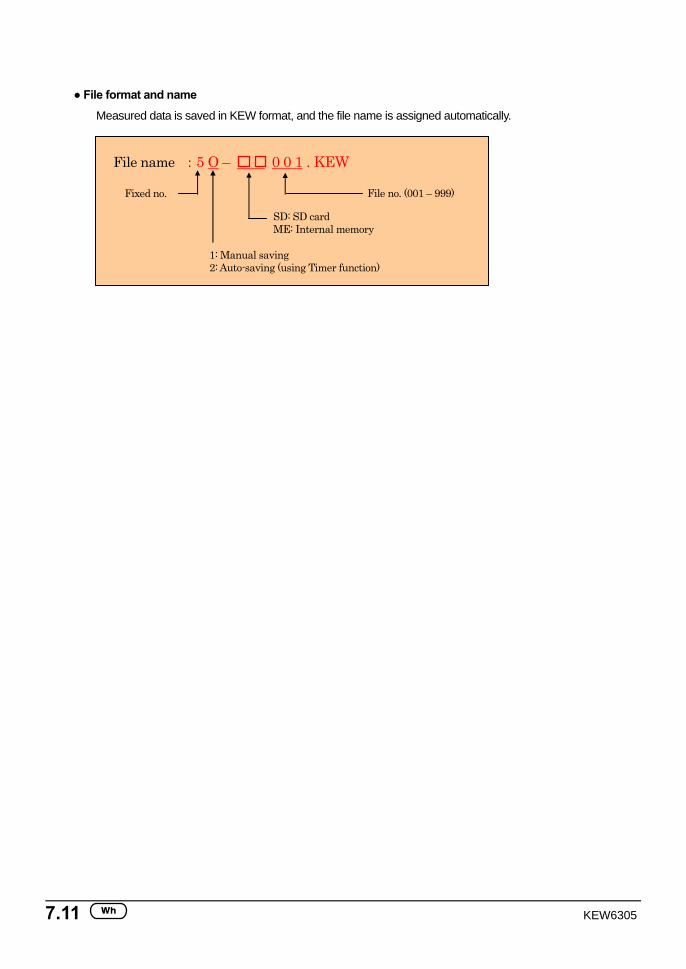
7.11 KEW6305
File format and name
Measured data is saved in KEW format, and the file name is assigned automatically.
File name :5 O – 0 0 1 . KEW
1: Manual saving 2: Auto-saving (using Timer function)
Fixed no.
SD: SD card ME: Internal memory
File no. (001 – 999)
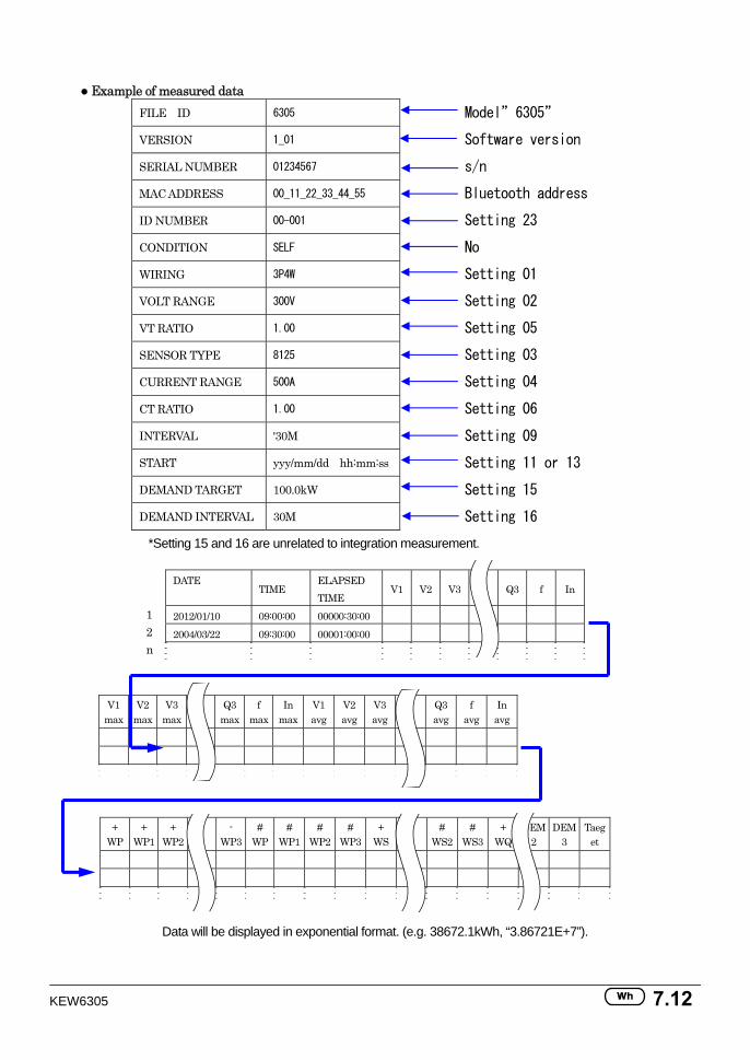
KEW6305 7.12
Example of measured data
FILE ID 6305 Model”6305”
VERSION 1_01 Software version
SERIAL NUMBER 01234567 s/n
MAC ADDRESS 00_11_22_33_44_55 Bluetooth address
ID NUMBER 00-001 Setting 23
CONDITION SELF No
WIRING 3P4W Setting 01
VOLT RANGE 300V Setting 02
VT RATIO 1.00 Setting 05
SENSOR TYPE 8125 Setting 03
CURRENT RANGE 500A Setting 04
CT RATIO 1.00 Setting 06
INTERVAL '30M Setting 09
START yyy/mm/dd hh:mm:ss Setting 11 or 13
DEMAND TARGET 100.0kW Setting 15
DEMAND INTERVAL 30M Setting 16
*Setting 15 and 16 are unrelated to integration measurement.
DATE TIME
ELAPSED TIME
V1 V2 V3 Q3 f In
2012/01/10 09:00:00 00000:30:00 2004/03/22 09:30:00 00001:00:00
V1 max
V2 max
V3 max Q3
maxf
max In
maxV1 avg
V2 avg
V3avg Q3
avgf
avgIn
avg
+ WP
+ WP1
+ WP2 -
WP3#
WP#
WP1#
WP2 #
WP3+
WS # WS2
# WS3
+ WQ
DEM2
DEM3
Taeget
Data will be displayed in exponential format. (e.g. 38672.1kWh, “3.86721E+7”).
1 2 n
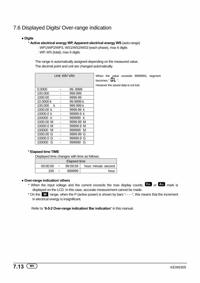
7.13 KEW6305
7.6 Displayed Digits/ Over-range indication
Digits * Active electrical energy WP, Apparent electrical energy WS (auto-range)
: WP1/WP2/WP3, WS1/WS2/WS3 (each phase), max 6 digits : WP, WS (total), max 6 digits
The range is automatically assigned depending on the measured value. The decimal point and unit are changed automatically.
Unit: Wh/ VAh When the value exceeds 999999G, segment
becomes “ “. However the saved data is not lost.
0.0000 - 99..9999 100.000 - 999.999 1000.00 - 9999.99 10.0000 k - 99.9999 k 100.000 k - 999.999 k 1000.00 k - 9999.99 k 10000.0 k - 99999.9 k 100000 k - 999999 k 1000.00 M - 9999.99 M 10000.0 M - 99999.9 M 100000 M - 999999 M 1000.00 G - 9999.99 G 10000.0 G - 99999.9 G 100000 G - 999999 G
* Elapsed time TIME
Displayed time changes with time as follows. Elapsed time
00:00:00 ~ 99:59:59 hour: minute: second100 ~ 999999 hour
Over-range indication/ others
* When the input voltage and the current exceeds the max display counts, or mark is displayed on the LCD. In this case, accurate measurement cannot be made.
* On the W range, when the P (active power) is shown by bars “- - - -”, this means that the increment in electrical energy is insignificant.
Refer to “6-5-2 Over-range indication/ Bar indication” in this manual.

KEW6305 7.14
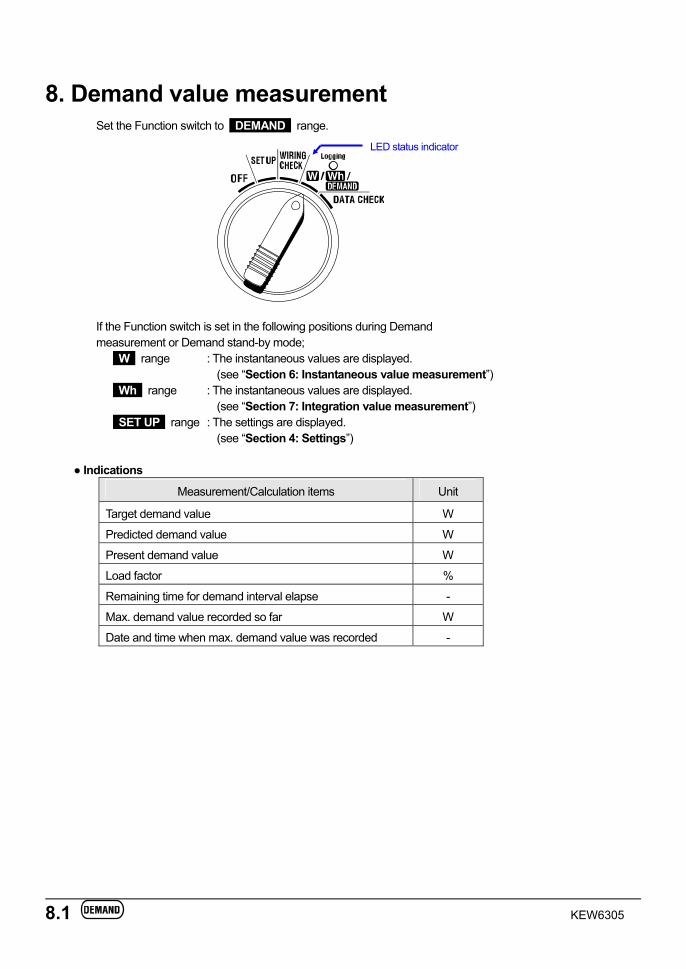
8.1 KEW6305
LED status indicator
8. Demand value measurement Set the Function switch to DEMAND range.
If the Function switch is set in the following positions during Demand measurement or Demand stand-by mode;
W range : The instantaneous values are displayed. (see “Section 6: Instantaneous value measurement”)
Wh range : The instantaneous values are displayed. (see “Section 7: Integration value measurement”)
SET UP range : The settings are displayed. (see “Section 4: Settings”)
Indications
Measurement/Calculation items Unit
Target demand value W
Predicted demand value W
Present demand value W
Load factor %
Remaining time for demand interval elapse -
Max. demand value recorded so far W
Date and time when max. demand value was recorded -
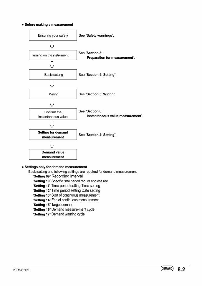
KEW6305 8.2
Before making a measurement
Ensuring your safety See “Safety warnings”.
Turning on the instrument See “Section 3:
Preparation for measurement”.
Basic setting See “Section 4: Setting”.
Wiring See “Section 5: Wiring”.
Confirm the instantaneous value
See “Section 6: Instantaneous value measurement”.
Setting for demand measurement See “Section 4: Setting”.
Demand value measurement
Settings only for demand measurement
Basic setting and following settings are required for demand measurement. “Setting 09” Recording interval “Setting 10” Specific time period rec. or endless rec. “Setting 11” Time period setting Time setting “Setting 12” Time period setting Date setting “Setting 13” Start of continuous measurement “Setting 14” End of continuous measurement “Setting 15” Target demand “Setting 16” Demand measure-ment cycle “Setting 17” Demand warning cycle
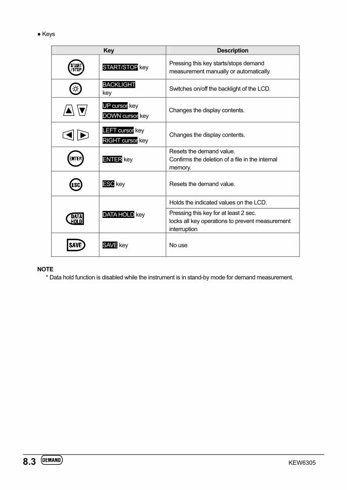
8.3 KEW6305
Keys
Key Description
START/STOP key Pressing this key starts/stops demand measurement manually or automatically.
BACKLIGHT key
Switches on/off the backlight of the LCD.
UP cursor key
DOWN cursor key Changes the display contents.
LEFT cursor key
RIGHT cursor key Changes the display contents.
ENTER key
Resets the demand value. Confirms the deletion of a file in the internal memory.
ESC key Resets the demand value.
Holds the indicated values on the LCD.
DATA HOLD key Pressing this key for at least 2 sec. locks all key operations to prevent measurement interruption
SAVE key No use
NOTE
* Data hold function is disabled while the instrument is in stand-by mode for demand measurement.
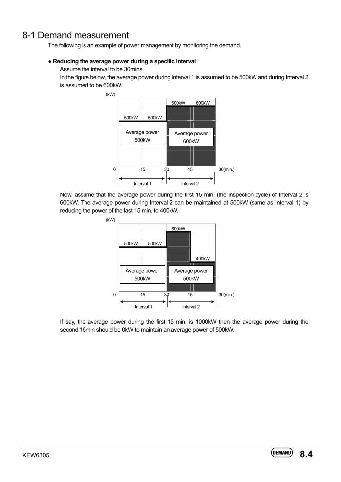
KEW6305 8.4
8-1 Demand measurement The following is an example of power management by monitoring the demand.
Reducing the average power during a specific interval
Assume the interval to be 30mins. In the figure below, the average power during Interval 1 is assumed to be 500kW and during Interval 2 is assumed to be 600kW.
(kW)
600kW 600kW
500kW 500kW
0 15 30 15 30(min.)
Now, assume that the average power during the first 15 min. (the inspection cycle) of Interval 2 is 600kW. The average power during Interval 2 can be maintained at 500kW (same as Interval 1) by reducing the power of the last 15 min. to 400kW.
(kW)
600kW
500kW 500kW
400kW
0 15 30 15 30(min.)
If say, the average power during the first 15 min. is 1000kW then the average power during the second 15min should be 0kW to maintain an average power of 500kW.
Average power 600kW
Interval 1 Interval 2
Average power 500kW
Interval 1 Interval 2
Average power 500kW
Average power 500kW
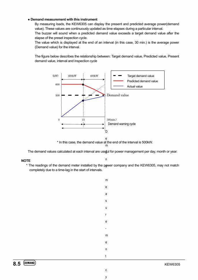
8.5 KEW6305
Demand measurement with this instrument By measuring loads, the KEW6305 can display the present and predicted average power(demand value). These values are continuously updated as time elapses during a particular interval. The buzzer will sound when a predicted demand value exceeds a target demand value after the elapse of the preset inspection cycle. The value which is displayed at the end of an interval (in this case, 30 min.) is the average power (Demand value) for the interval. The figure below describes the relationship between: Target demand value, Predicted value, Present demand value, interval and inspection cycle
(kW) 600kW 400kW
600
500
Demand value
0 15 30(min.)
* In this case, the demand value at the end of the interval is 500kW.
The demand values calculated at each interval are useful for power management per day, month or year.
NOTE * The readings of the demand meter installed by the power company and the KEW6305, may not match
completely due to a time-lag in the start of intervals.
D
e
m
a
n
d
m
e
a
s
u
r
e
-
m
e
n
t
c
y
Demand warning cycle
Target demand value Predicted demand value Actual value
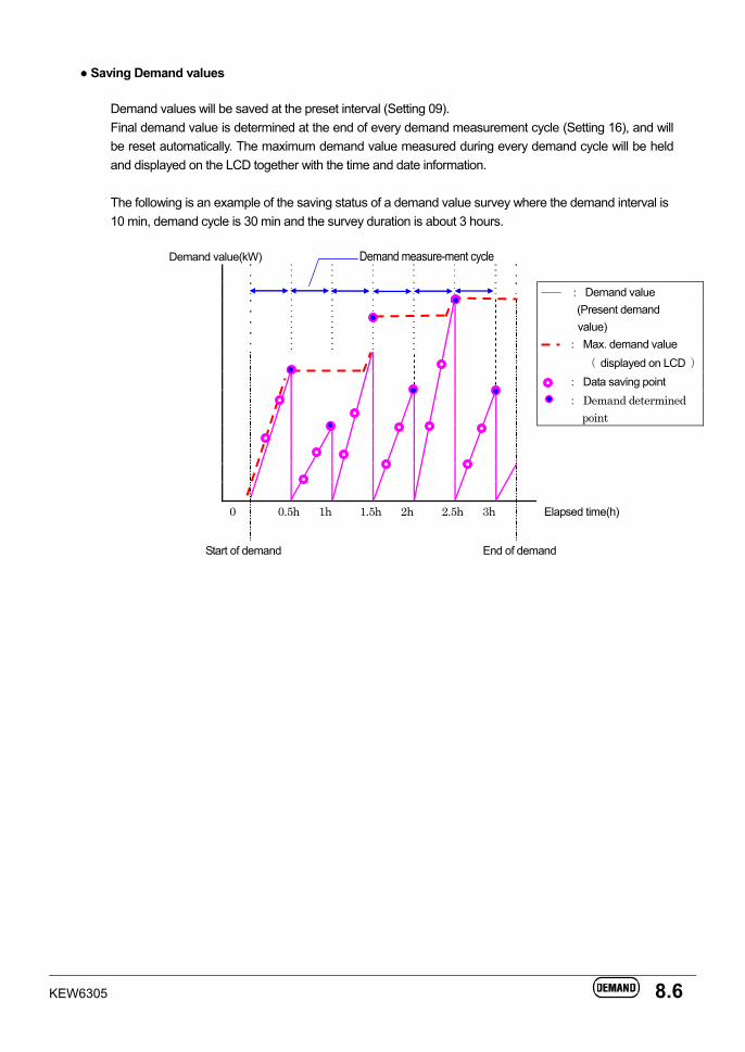
KEW6305 8.6
Saving Demand values
Demand values will be saved at the preset interval (Setting 09). Final demand value is determined at the end of every demand measurement cycle (Setting 16), and will be reset automatically. The maximum demand value measured during every demand cycle will be held and displayed on the LCD together with the time and date information. The following is an example of the saving status of a demand value survey where the demand interval is 10 min, demand cycle is 30 min and the survey duration is about 3 hours.
Demand value(kW) Demand measure-ment cycle
Start of demand End of demand
: Demand value (Present demand value) : Max. demand value
( displayed on LCD ) : Data saving point : Demand determined
point
0 0.5h 1h 1.5h 2h 2.5h 3h Elapsed time(h)
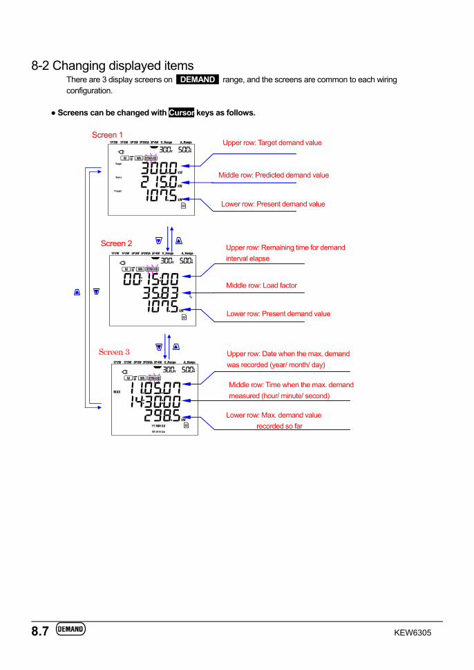
8.7 KEW6305
8-2 Changing displayed items
There are 3 display screens on DEMAND range, and the screens are common to each wiring configuration.
Screens can be changed with Cursor keys as follows.
Middle row: Predicted demand value
Upper row: Target demand value
Lower row: Present demand value
Middle row: Load factor
Upper row: Remaining time for demandinterval elapse
Lower row: Present demand value
Middle row: Time when the max. demand measured (hour/ minute/ second)
Upper row: Date when the max. demandwas recorded (year/ month/ day)
Screen 2
Screen 3
Lower row: Max. demand value recorded so far
Screen 1
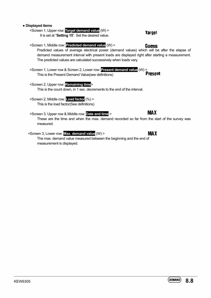
KEW6305 8.8
Displayed items
<Screen 1, Upper row: Target demand value (W) > It is set at “Setting 15”. Set the desired value.
<Screen 1, Middle row: Predicted demand value (W) >
Predicted values of average electrical power (demand values) which will be after the elapse of demand measurement interval with present loads are displayed right after starting a measurement. The predicted values are calculated successively when loads vary.
<Screen 1, Lower row & Screen 2, Lower row: Present demand value (W) >
This is the Present Demand Value(see definitions) <Screen 2, Upper row: Remaining time>
This is the count down, in 1 sec. decrements to the end of the interval.
<Screen 2, Middle row: Load factor (%) > This is the load factor(See definitions)
<Screen 3, Upper row & Middle row: Date and time >
These are the time and when the max. demand recorded so far from the start of the survey was measured.
<Screen 3, Lower row: Max. demand value (W) >
The max. demand value measured between the beginning and the end of measurement is displayed.
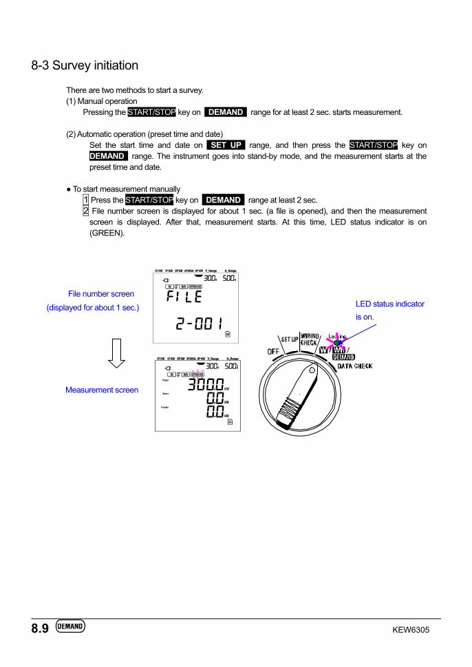
8.9 KEW6305
8-3 Survey initiation
There are two methods to start a survey. (1) Manual operation
Pressing the START/STOP key on DEMAND range for at least 2 sec. starts measurement.
(2) Automatic operation (preset time and date) Set the start time and date on SET UP range, and then press the START/STOP key on DEMAND range. The instrument goes into stand-by mode, and the measurement starts at the preset time and date.
To start measurement manually
1 Press the START/STOP key on DEMAND range at least 2 sec. 2 File number screen is displayed for about 1 sec. (a file is opened), and then the measurement
screen is displayed. After that, measurement starts. At this time, LED status indicator is on (GREEN).
File number screen
(displayed for about 1 sec.)
Measurement screen
LED status indicator is on.
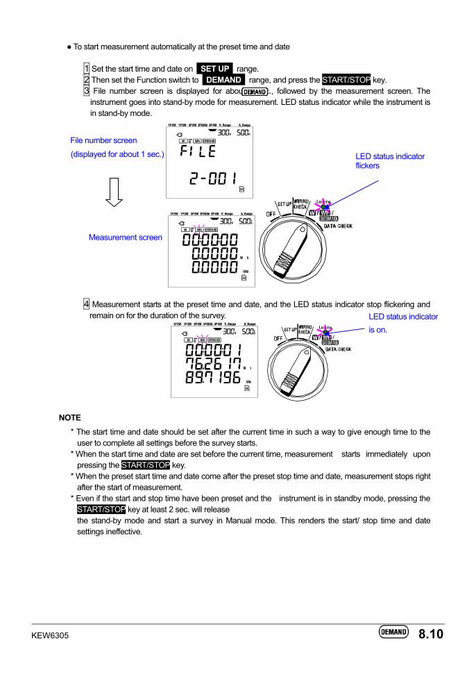
KEW6305 8.10
To start measurement automatically at the preset time and date
1 Set the start time and date on SET UP range. 2 Then set the Function switch to DEMAND range, and press the START/STOP key. 3 File number screen is displayed for about 1 sec., followed by the measurement screen. The
instrument goes into stand-by mode for measurement. LED status indicator while the instrument is in stand-by mode.
File number screen
(displayed for about 1 sec.)
Measurement screen
4 Measurement starts at the preset time and date, and the LED status indicator stop flickering and remain on for the duration of the survey.
NOTE
* The start time and date should be set after the current time in such a way to give enough time to the user to complete all settings before the survey starts.
* When the start time and date are set before the current time, measurement starts immediately upon pressing the START/STOP key.
* When the preset start time and date come after the preset stop time and date, measurement stops right after the start of measurement.
* Even if the start and stop time have been preset and the instrument is in standby mode, pressing the START/STOP key at least 2 sec. will release
the stand-by mode and start a survey in Manual mode. This renders the start/ stop time and date settings ineffective.
LED status indicator flickers
LED status indicator is on.
8.11 KEW6305
8-4 Survey closure
There are two methods for closing a survey. (1) Manual operation
Pressing START/STOP key on DEMAND range for at least 2 sec. stops measurement. This action also stops the measurement started automatically at a preset date and time.
(2) Automatic operation (specifying the time and date)
Preset the stop time and date on SET UP range .
To stop measurement manually * Pressing START/STOP key on DEMAND range for at least 2 sec. stops the measurement. When it stops, (in case data is to be saved to CF card) the LED status indicator goes off.
To stop measurement automatically at the preset time and date
Set the stop time and date on SET UP range. This method is available only when the measurement is started at the preset time and date. When the preset stop time and date has been reached, (in case data to be saved to CF card) and LED status indicator goes off. The survey is then closed.
NOTE * Turning off the instrument ( by setting the Function switch to OFF position) will stop the survey, however
the measured data may be lost. It is recommended that a survey be stopped manually (START/STOP key) or by presetting the stop time and date.
* Manually starting a survey renders a preset stop time and date ineffective. The survey has to be closed manually in this case.
* If the preset start time and date come after the preset stop time and date, the survey cannot be done.
8-5 Resetting the demand value
There are two methods for resetting (deleting) the current demand values on the display screen.
* Press ESC key on DEMAND range at least 2 sec. * System reset
NOTE * If it is desired to retain the integration value, start demand measurement without resetting the demand values. The items on DEMAND range other than the max. demand value and corresponding time and date, are reset automatically.
* Demand value cannot be reset during a measurement or while the instrument is in stand-by mode.
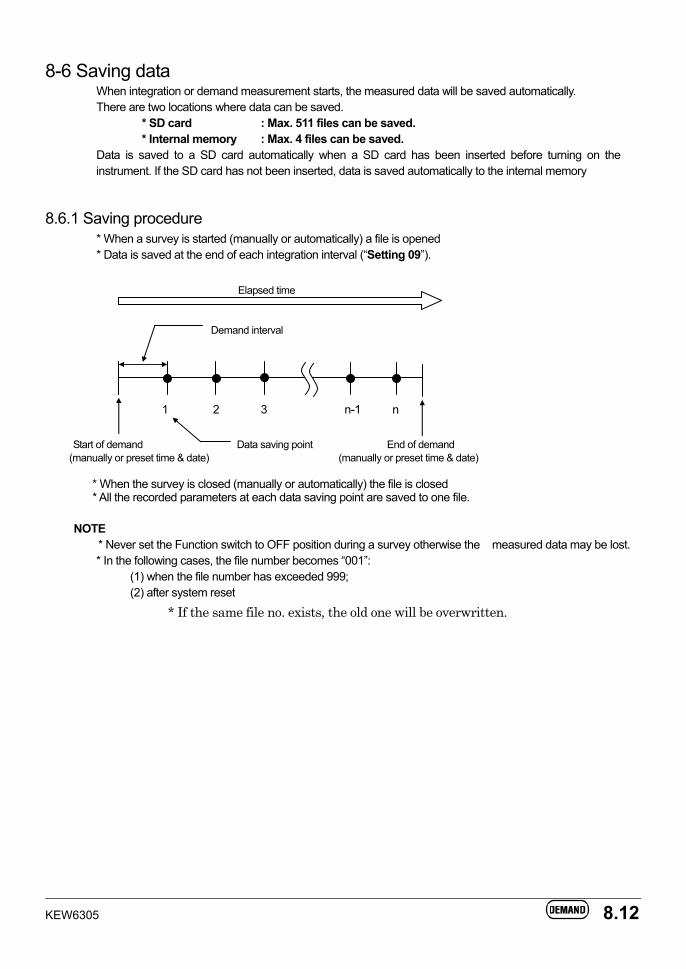
KEW6305 8.12
8-6 Saving data When integration or demand measurement starts, the measured data will be saved automatically. There are two locations where data can be saved.
* SD card : Max. 511 files can be saved. * Internal memory : Max. 4 files can be saved.
Data is saved to a SD card automatically when a SD card has been inserted before turning on the instrument. If the SD card has not been inserted, data is saved automatically to the internal memory
8.6.1 Saving procedure * When a survey is started (manually or automatically) a file is opened * Data is saved at the end of each integration interval (“Setting 09”).
Elapsed time
Demand interval
1 2 3 n-1 n
Start of demand Data saving point End of demand
(manually or preset time & date) (manually or preset time & date)
* When the survey is closed (manually or automatically) the file is closed * All the recorded parameters at each data saving point are saved to one file.
NOTE
* Never set the Function switch to OFF position during a survey otherwise the measured data may be lost. * In the following cases, the file number becomes “001”:
(1) when the file number has exceeded 999; (2) after system reset
* If the same file no. exists, the old one will be overwritten.
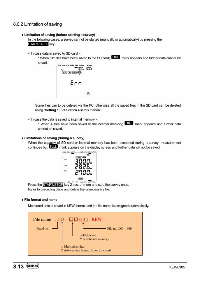
8.13 KEW6305
150V 300V 600V 1P2W 1P3W 3P3W 3P4W
5A 10A 20A 50A 100A 200A 500A 1000A
8.6.2 Limitation of saving
Limitation of saving (before starting a survey) In the following cases, a survey cannot be started (manually or automatically) by pressing the START/STOP key.
< In case data is saved to SD card >
* When 511 files have been saved to the SD card; mark appears and further data cannot be saved.
Some files can to be deleted via the PC, otherwise all the saved files in the SD card can be deleted using “Setting 19” of Section 4 in this manual.
< In case the data is saved to internal memory >
* When 4 files have been saved to the internal memory; mark appears and further data cannot be saved.
Limitations of saving (during a survey)
When the capacity of SD card or internal memory has been exceeded during a survey; measurement continues but mark appears on the display screen and further data will not be saved.
Press the START/STOP key 2 sec. or more and stop the survey once. Refer to preceding page and delete the unnecessary file.
File format and name
Measured data is saved in KEW format, and the file name is assigned automatically.
File name :5 O – 0 0 1 . KEW
1: Manual saving 2: Auto-saving (using Timer function)
Fixed no.
SD: SD card ME: Internal memory
File no. (001 – 999)
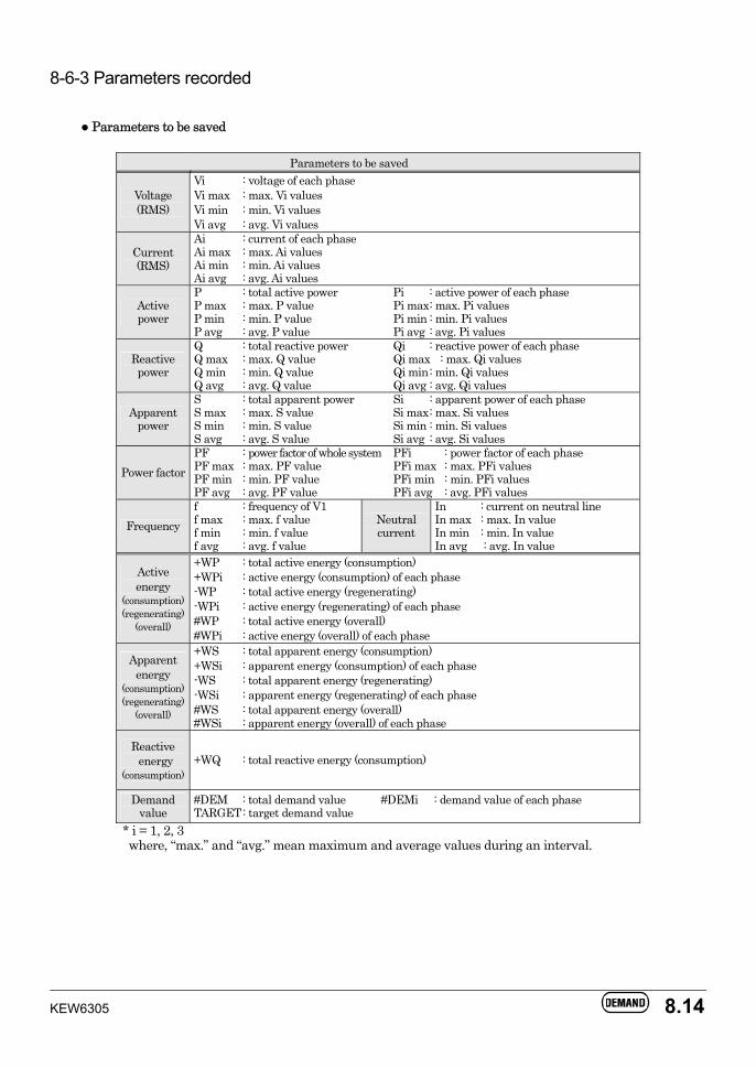
KEW6305 8.14
8-6-3 Parameters recorded
Parameters to be saved
Parameters to be saved
Voltage (RMS)
Vi : voltage of each phase Vi max : max. Vi values Vi min : min. Vi values Vi avg : avg. Vi values
Current (RMS)
Ai : current of each phase Ai max : max. Ai values Ai min : min. Ai values Ai avg : avg. Ai values
Active power
P : total active power Pi : active power of each phase P max : max. P value Pi max : max. Pi values P min : min. P value Pi min : min. Pi values P avg : avg. P value Pi avg : avg. Pi values
Reactive power
Q : total reactive power Qi : reactive power of each phase Q max : max. Q value Qi max : max. Qi values Q min : min. Q value Qi min : min. Qi values Q avg : avg. Q value Qi avg : avg. Qi values
Apparent power
S : total apparent power Si : apparent power of each phase S max : max. S value Si max : max. Si values S min : min. S value Si min : min. Si values S avg : avg. S value Si avg : avg. Si values
Power factor PF : power factor of whole system PFi : power factor of each phase PF max : max. PF value PFi max : max. PFi values PF min : min. PF value PFi min : min. PFi values PF avg : avg. PF value PFi avg : avg. PFi values
Frequency f : frequency of V1 f max : max. f value f min : min. f value f avg : avg. f value
Neutral current
In : current on neutral line In max : max. In value In min : min. In value In avg : avg. In value
Active energy
(consumption) (regenerating)
(overall)
+WP : total active energy (consumption) +WPi : active energy (consumption) of each phase -WP : total active energy (regenerating) -WPi : active energy (regenerating) of each phase #WP : total active energy (overall) #WPi : active energy (overall) of each phase
Apparent energy
(consumption) (regenerating)
(overall)
+WS : total apparent energy (consumption) +WSi : apparent energy (consumption) of each phase -WS : total apparent energy (regenerating) -WSi : apparent energy (regenerating) of each phase #WS : total apparent energy (overall) #WSi : apparent energy (overall) of each phase
Reactive energy
(consumption) +WQ : total reactive energy (consumption)
Demand value
#DEM : total demand value #DEMi : demand value of each phase TARGET : target demand value
* i = 1, 2, 3 where, “max.” and “avg.” mean maximum and average values during an interval.
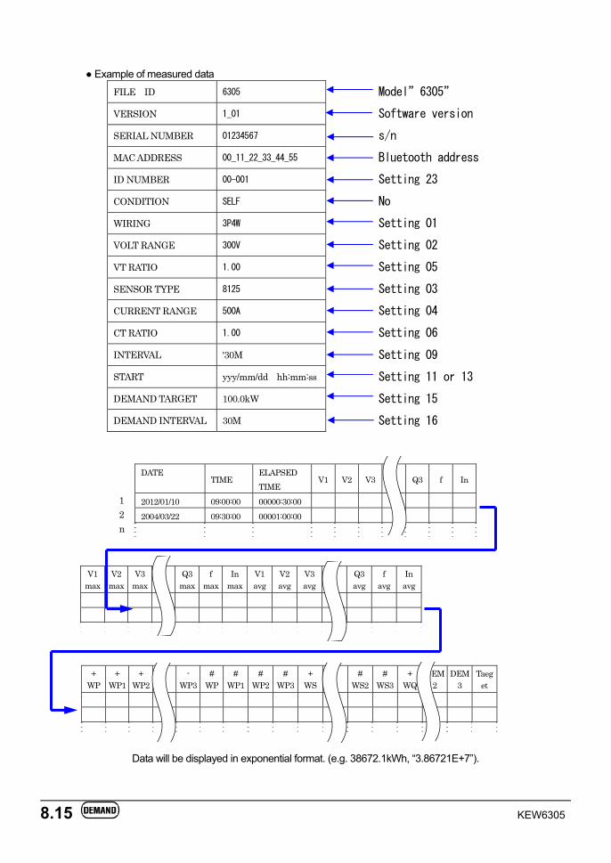
8.15 KEW6305
Example of measured data FILE ID 6305 Model”6305”
VERSION 1_01 Software version
SERIAL NUMBER 01234567 s/n
MAC ADDRESS 00_11_22_33_44_55 Bluetooth address
ID NUMBER 00-001 Setting 23
CONDITION SELF No
WIRING 3P4W Setting 01
VOLT RANGE 300V Setting 02
VT RATIO 1.00 Setting 05
SENSOR TYPE 8125 Setting 03
CURRENT RANGE 500A Setting 04
CT RATIO 1.00 Setting 06
INTERVAL '30M Setting 09
START yyy/mm/dd hh:mm:ss Setting 11 or 13
DEMAND TARGET 100.0kW Setting 15
DEMAND INTERVAL 30M Setting 16
DATE TIME
ELAPSED TIME
V1 V2 V3 Q3 f In
2012/01/10 09:00:00 00000:30:00 2004/03/22 09:30:00 00001:00:00
V1 max
V2 max
V3 max Q3
maxf
max In
maxV1 avg
V2 avg
V3avg Q3
avgf
avgIn
avg
+ WP
+ WP1
+ WP2 -
WP3#
WP#
WP1#
WP2 #
WP3+
WS # WS2
# WS3
+ WQ
DEM2
DEM3
Taeget
Data will be displayed in exponential format. (e.g. 38672.1kWh, “3.86721E+7”).
1 2 n
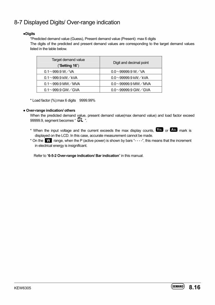
KEW6305 8.16
8-7 Displayed Digits/ Over-range indication
Digits *Predicted demand value (Guess), Present demand value (Present): max 6 digits The digits of the predicted and present demand values are corresponding to the target demand values listed in the table below.
Target demand value (“Setting 16”)
Digit and decimal point
0.1~999.9 W/VA 0.0~99999.9 W/VA 0.1~999.9 kW/kVA 0.0~99999.9 kW/kVA 0.1~999.9 MW/MVA 0.0~99999.9 MW/MVA 0.1~999.9 GW/GVA 0.0~99999.9 GW/GVA
* Load factor (%):max 6 digits 9999.99%
Over-range indication/ others When the predicted demand value, present demand value(max demand value) and load factor exceed 99999.9, segment becomes “ ”. * When the input voltage and the current exceeds the max display counts, or mark is
displayed on the LCD. In this case, accurate measurement cannot be made. * On the W range, when the P (active power) is shown by bars “- - - -”, this means that the increment
in electrical energy is insignificant. Refer to “6-5-2 Over-range indication/ Bar indication” in this manual.
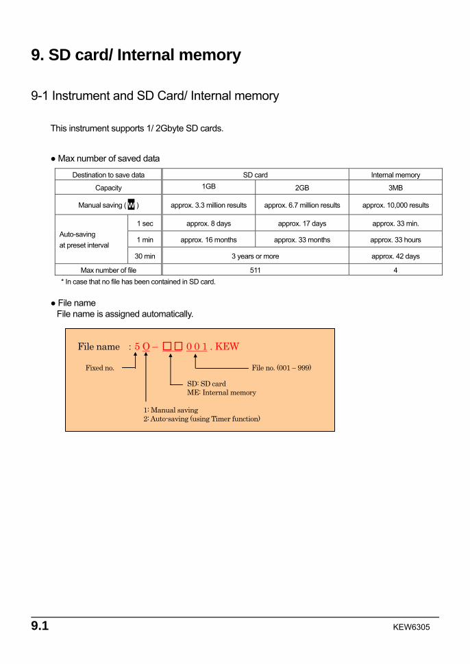
9.1 KEW6305
9. SD card/ Internal memory
9-1 Instrument and SD Card/ Internal memory
This instrument supports 1/ 2Gbyte SD cards.
Max number of saved data
Destination to save data SD card Internal memory
Capacity 1GB 2GB 3MB
Manual saving ( W ) approx. 3.3 million results approx. 6.7 million results approx. 10,000 results
1 sec approx. 8 days approx. 17 days approx. 33 min.
1 min approx. 16 months approx. 33 months approx. 33 hours Auto-saving at preset interval
30 min 3 years or more approx. 42 days
Max number of file 511 4 * In case that no file has been contained in SD card.
File name
File name is assigned automatically.
File name :5 O – 0 0 1 . KEW
1: Manual saving 2: Auto-saving (using Timer function)
Fixed no.
SD: SD card ME: Internal memory
File no. (001 – 999)
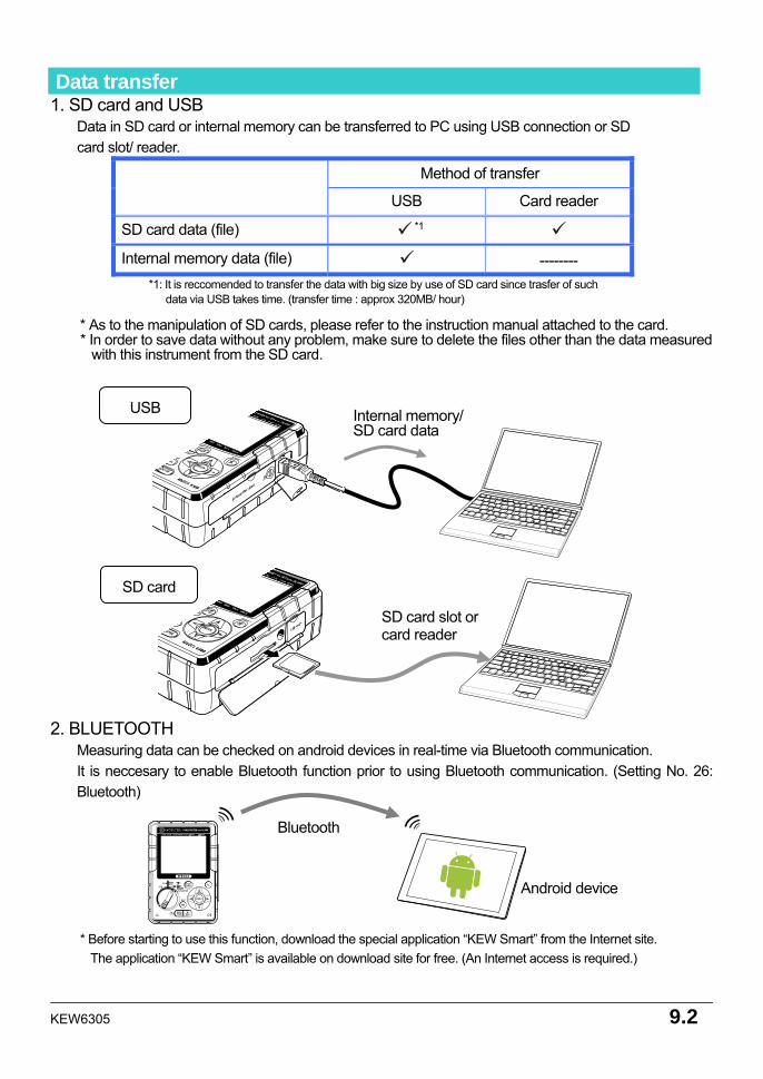
KEW6305 9.2
Data transfer 1. SD card and USB
Data in SD card or internal memory can be transferred to PC using USB connection or SD card slot/ reader.
Method of transfer USB Card reader
SD card data (file) *1
Internal memory data (file) -------- *1: It is reccomended to transfer the data with big size by use of SD card since trasfer of such
data via USB takes time. (transfer time : approx 320MB/ hour)
* As to the manipulation of SD cards, please refer to the instruction manual attached to the card. * In order to save data without any problem, make sure to delete the files other than the data measured
with this instrument from the SD card.
2. BLUETOOTH Measuring data can be checked on android devices in real-time via Bluetooth communication. It is neccesary to enable Bluetooth function prior to using Bluetooth communication. (Setting No. 26: Bluetooth)
* Before starting to use this function, download the special application “KEW Smart” from the Internet site. The application “KEW Smart” is available on download site for free. (An Internet access is required.)
Bluetooth
Android device
Internal memory/ SD card data
USB
SD card
SD card slot or card reader
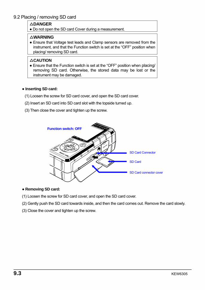
9.3 KEW6305
9.2 Placing / removing SD card DANGER Do not open the SD card Cover during a measurement.
WARNING Ensure that Voltage test leads and Clamp sensors are removed from the
instrument, and that the Function switch is set at the “OFF” position when placing/ removing SD card.
CAUTION Ensure that the Function switch is set at the “OFF” position when placing/
removing SD card. Otherwise, the stored data may be lost or the instrument may be damaged.
Inserting SD card:
(1) Loosen the screw for SD card cover, and open the SD card cover.
(2) Insert an SD card into SD card slot with the topside turned up.
(3) Then close the cover and tighten up the screw.
Removing SD card:
(1) Loosen the screw for SD card cover, and open the SD card cover.
(2) Gently push the SD card towards inside, and then the card comes out. Remove the card slowly.
(3) Close the cover and tighten up the screw.
Function switch: OFF
SD Card connector cover
SD Card
SD Card Connector

KEW6305 9.4
10.1 KEW6305
10. Communication function/ Interface software 1. Introduction
Interface This instrument is equipped with USB and Bluetooth interfaces. Communication method : USB Ver2.0 Bluetooth : Bluetooth Ver2.1+EDR (Class2) Compliant profile: SPP Following can be done by USB/ Bluetooth communication. * Downloading files in the internal memory of the instrument to a PC * Making settings for the instrument via a PC * Displaying the measured results on a PC as graphs in real-time,
and also saving the measured data at the same time System Requirements
* OS(Operation System) Windows7/Vista/XP (CPU: Pentium 4 1.6GHz or more)
* Memory 512Mbyte or more (for Windows XP), 1Gbyte or more (for Windows 7/ Vista)
* Display 1024 × 768 dots, 65536 colors or more
* HDD (Hard-disk space required) 1Gbyte or more (including Framework)
*.NET Framework (3.5 or more) Trademark
* Windows® is a registered trademark of Microsoft in the United States. * Pentium is a registered trademark of Intel in the United States. * Bluetooth is a registered trademark of Bluetooth SIG.
The latest software is available for download from our homepage. http://www.kew-ltd.co.jp
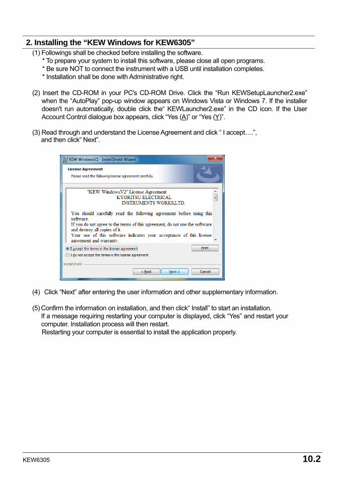
KEW6305 10.2
(1) Followings shall be checked before installing the software. * To prepare your system to install this software, please close all open programs. * Be sure NOT to connect the instrument with a USB until installation completes. * Installation shall be done with Administrative right.
(2) Insert the CD-ROM in your PC's CD-ROM Drive. Click the “Run KEWSetupLauncher2.exe”
when the “AutoPlay” pop-up window appears on Windows Vista or Windows 7. If the installer doesn't run automatically, double click the“ KEWLauncher2.exe” in the CD icon. If the User Account Control dialogue box appears, click “Yes (A)” or “Yes (Y)”.
(3) Read through and understand the License Agreement and click “ I accept….”,
and then click“ Next”. (4) Click “Next” after entering the user information and other supplementary information. (5) Confirm the information on installation, and then click“ Install” to start an installation.
If a message requiring restarting your computer is displayed, click “Yes” and restart your computer. Installation process will then restart.
Restarting your computer is essential to install the application properly.
2. Installing the “KEW Windows for KEW6305”
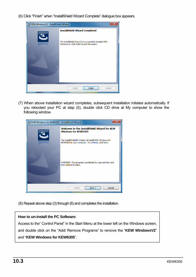
10.3 KEW6305
(6) Click “Finish” when “InstallShield Wizard Complete” dialogue box appears. (7) When above installation wizard completes, subsequent installation initiates automatically. If
you rebooted your PC at step (5), double click CD drive at My computer to show the following window.
(8) Repeat above step (3) through (6) and completes the installation.
How to un-install the PC Software:
Access to the“ Control Panel” in the Start Menu at the lower left on the Windows screen,
and double click on the “Add/ Remove Programs” to remove the “KEW WindowsV2”
and “KEW Windows for KEW6305”.
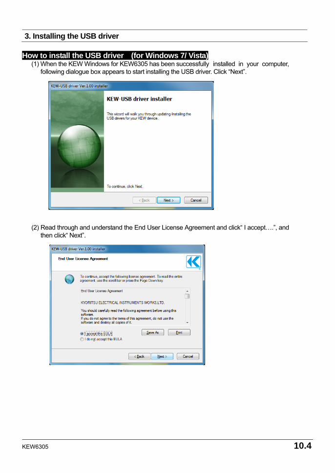
KEW6305 10.4
3. Installing the USB driver
How to install the USB driver (for Windows 7/ Vista)
(1) When the KEW Windows for KEW6305 has been successfully installed in your computer, following dialogue box appears to start installing the USB driver. Click “Next”.
(2) Read through and understand the End User License Agreement and click“ I accept….”, and
then click“ Next”.
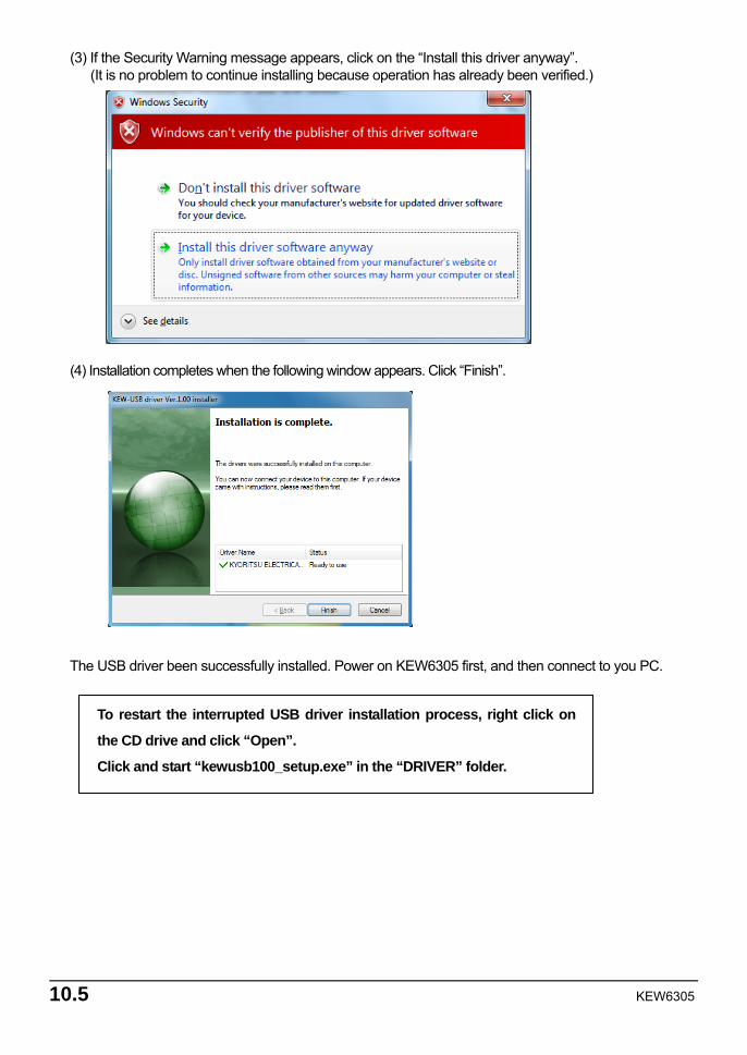
10.5 KEW6305
(3) If the Security Warning message appears, click on the “Install this driver anyway”. (It is no problem to continue installing because operation has already been verified.)
(4) Installation completes when the following window appears. Click “Finish”. The USB driver been successfully installed. Power on KEW6305 first, and then connect to you PC.
To restart the interrupted USB driver installation process, right click on
the CD drive and click “Open”.
Click and start “kewusb100_setup.exe” in the “DRIVER” folder.
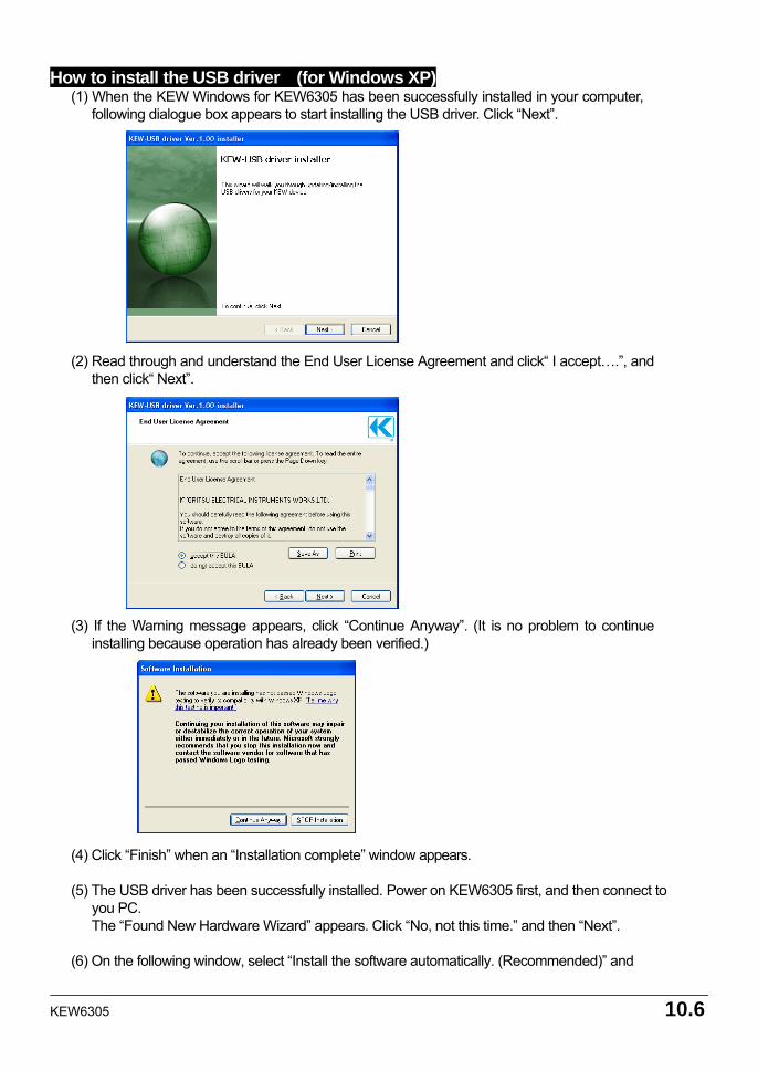
KEW6305 10.6
How to install the USB driver (for Windows XP)
(1) When the KEW Windows for KEW6305 has been successfully installed in your computer, following dialogue box appears to start installing the USB driver. Click “Next”.
(2) Read through and understand the End User License Agreement and click“ I accept….”, and
then click“ Next”. (3) If the Warning message appears, click “Continue Anyway”. (It is no problem to continue
installing because operation has already been verified.) (4) Click “Finish” when an “Installation complete” window appears. (5) The USB driver has been successfully installed. Power on KEW6305 first, and then connect to
you PC. The “Found New Hardware Wizard” appears. Click “No, not this time.” and then “Next”.
(6) On the following window, select “Install the software automatically. (Recommended)” and
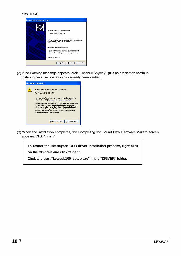
10.7 KEW6305
click “Next”. (7) If the Warning message appears, click “Continue Anyway”. (It is no problem to continue
installing because operation has already been verified.) (8) When the installation completes, the Completing the Found New Hardware Wizard screen
appears. Click “Finish”.
To restart the interrupted USB driver installation process, right click
on the CD drive and click “Open”.
Click and start “kewusb100_setup.exe” in the “DRIVER” folder.
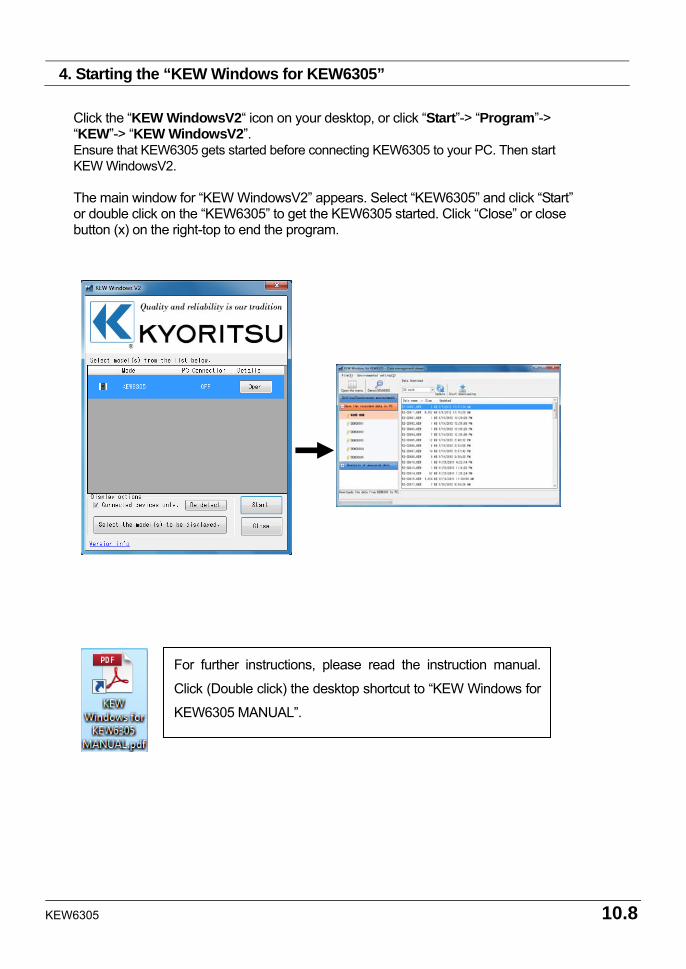
KEW6305 10.8
4. Starting the “KEW Windows for KEW6305”
Click the “KEW WindowsV2“ icon on your desktop, or click “Start”-> “Program”-> “KEW”-> “KEW WindowsV2”. Ensure that KEW6305 gets started before connecting KEW6305 to your PC. Then start KEW WindowsV2. The main window for “KEW WindowsV2” appears. Select “KEW6305” and click “Start” or double click on the “KEW6305” to get the KEW6305 started. Click “Close” or close button (x) on the right-top to end the program.
For further instructions, please read the instruction manual.
Click (Double click) the desktop shortcut to “KEW Windows for
KEW6305 MANUAL”.
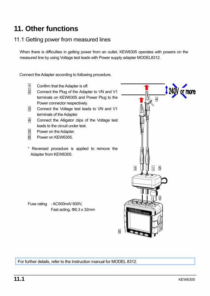
11.1 KEW6305
11. Other functions 11.1 Getting power from measured lines
When there is difficulties in getting power from an outlet, KEW6305 operates with powers on the measured line by using Voltage test leads with Power supply adapter MODEL8312. Connect the Adapter according to following procedure.
1 Confirm that the Adapter is off. 2 Connect the Plug of the Adapter to VN and V1
terminals on KEW6305 and Power Plug to the Power connector respectively.
3 Connect the Voltage test leads to VN and V1 terminals of the Adapter.
4 Connect the Alligator clips of the Voltage test leads to the circuit under test.
5 Power on the Adapter. 6 Power on KEW6305. * Reversed procedure is applied to remove the
Adapter from KEW6305.
Fuse rating : AC500mA/ 600V, Fast acting, Φ6.3 x 32mm
For further details, refer to the Instruction manual for MODEL 8312.
1
2
3
4
5
6
KEW6305 11.2
11.2 Auto-ranging
Auto-ranging function is available at W, Wh, DEMAND and WAVE Ranges. Current values in wide range can be measured with this function; it is helpful when load capacitances vary dramatically according to day and time. Range: 2-range-auto/ max and min range of each Clamp sensor Range shift to upper one when crest values equal to twice as much as F.S (sine wave) at min
range is detected.
Accurate values may not be obtained when substantial fluctuations in 1 sec.
11.3 Operation at AC power interruption When an AC power supply is interrupted during recording, KEW6310 operates as follows.
Power supply : restores to battery when batteries have been installed Measurement data : saved until the last interval before an interruption Operation after interruption : recording restarts with preset settings if a power is
interrupted during recording. In this case, occurrence of interruption is recorded with time and date information. (STOP) Restoration is also recorded as well. (START) Instrument doesn’t power on again automatically when a power interruption occurs and restores other than recording period.
Files in CF card or Internal memory may be destroyed if an AC power is interrupted while accessing to them. Use of AC power supply and batteries at the same time is recommended if power interruptions are concerned.
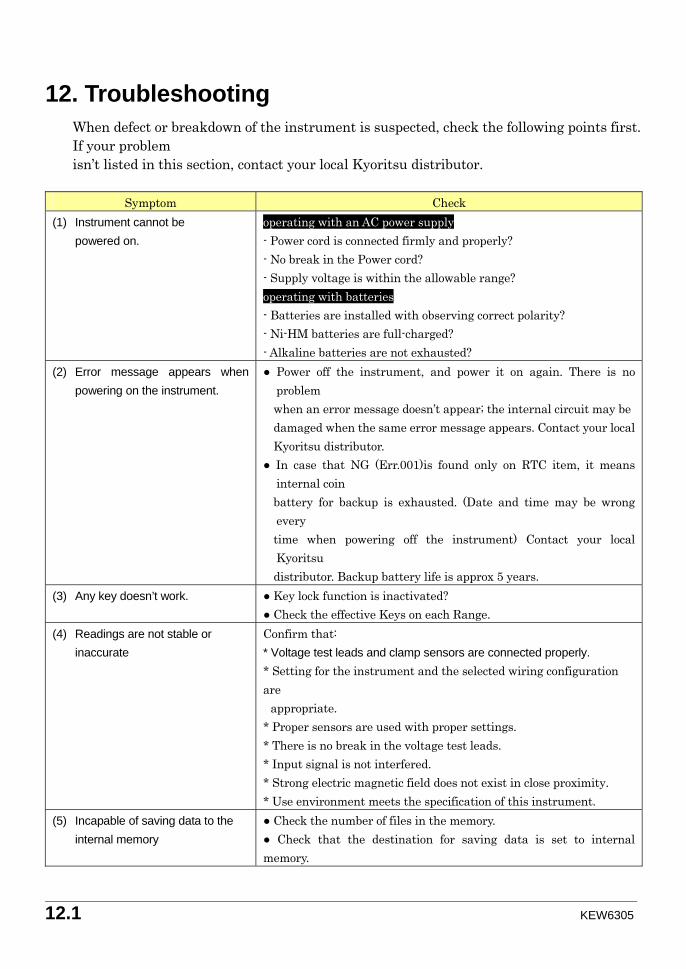
12.1 KEW6305
12. Troubleshooting When defect or breakdown of the instrument is suspected, check the following points first. If your problem isn’t listed in this section, contact your local Kyoritsu distributor.
Symptom Check (1) Instrument cannot be powered on.
operating with an AC power supply - Power cord is connected firmly and properly? - No break in the Power cord? - Supply voltage is within the allowable range? operating with batteries - Batteries are installed with observing correct polarity? - Ni-HM batteries are full-charged? - Alkaline batteries are not exhausted?
(2) Error message appears when powering on the instrument.
Power off the instrument, and power it on again. There is no problem
when an error message doesn’t appear; the internal circuit may be damaged when the same error message appears. Contact your local Kyoritsu distributor. In case that NG (Err.001)is found only on RTC item, it means
internal coin battery for backup is exhausted. (Date and time may be wrong
every time when powering off the instrument) Contact your local
Kyoritsu distributor. Backup battery life is approx 5 years.
(3) Any key doesn’t work.
Key lock function is inactivated? Check the effective Keys on each Range.
(4) Readings are not stable or inaccurate
Confirm that: * Voltage test leads and clamp sensors are connected properly. * Setting for the instrument and the selected wiring configuration are
appropriate. * Proper sensors are used with proper settings. * There is no break in the voltage test leads. * Input signal is not interfered. * Strong electric magnetic field does not exist in close proximity. * Use environment meets the specification of this instrument.
(5) Incapable of saving data to the internal memory
Check the number of files in the memory. Check that the destination for saving data is set to internal memory.
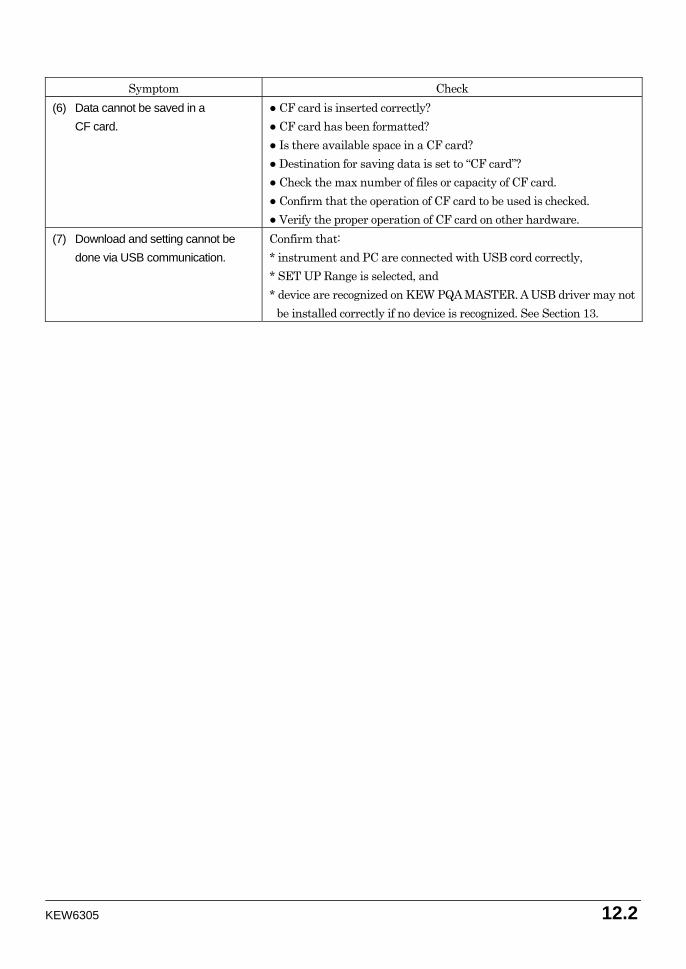
KEW6305 12.2
Symptom Check
(6) Data cannot be saved in a CF card.
CF card is inserted correctly? CF card has been formatted? Is there available space in a CF card? Destination for saving data is set to “CF card”? Check the max number of files or capacity of CF card. Confirm that the operation of CF card to be used is checked. Verify the proper operation of CF card on other hardware.
(7) Download and setting cannot be done via USB communication.
Confirm that: * instrument and PC are connected with USB cord correctly, * SET UP Range is selected, and * device are recognized on KEW PQA MASTER. A USB driver may not
be installed correctly if no device is recognized. See Section 13.
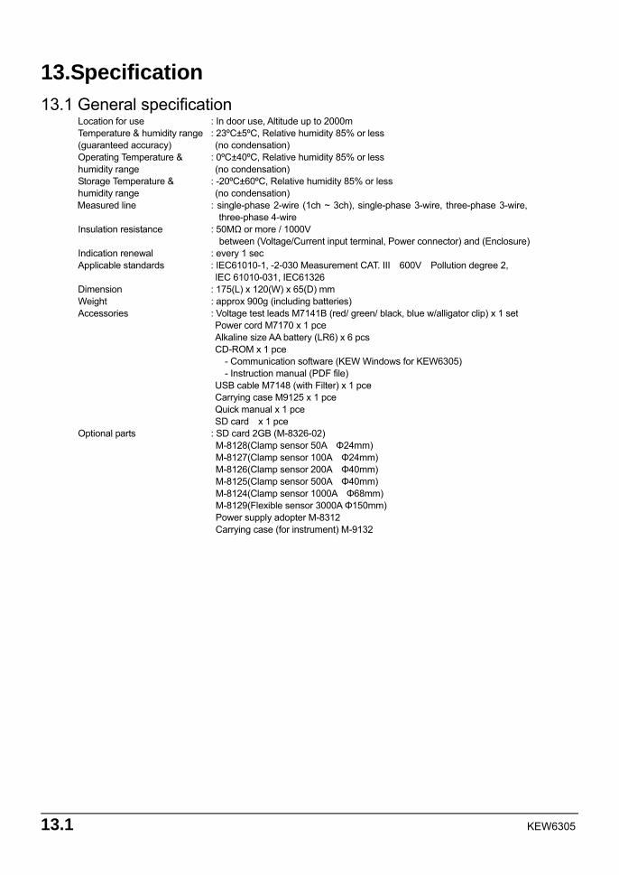
13.1 KEW6305
13.Specification 13.1 General specification
Location for use : In door use, Altitude up to 2000m Temperature & humidity range : 23ºC±5ºC, Relative humidity 85% or less (guaranteed accuracy) (no condensation) Operating Temperature & : 0ºC±40ºC, Relative humidity 85% or less humidity range (no condensation) Storage Temperature & : -20ºC±60ºC, Relative humidity 85% or less humidity range (no condensation) Measured line : single-phase 2-wire (1ch ~ 3ch), single-phase 3-wire, three-phase 3-wire,
three-phase 4-wire Insulation resistance : 50MΩ or more / 1000V
between (Voltage/Current input terminal, Power connector) and (Enclosure) Indication renewal : every 1 sec Applicable standards : IEC61010-1, -2-030 Measurement CAT. III 600V Pollution degree 2, IEC 61010-031, IEC61326 Dimension : 175(L) x 120(W) x 65(D) mm Weight : approx 900g (including batteries) Accessories : Voltage test leads M7141B (red/ green/ black, blue w/alligator clip) x 1 set Power cord M7170 x 1 pce Alkaline size AA battery (LR6) x 6 pcs CD-ROM x 1 pce - Communication software (KEW Windows for KEW6305) - Instruction manual (PDF file) USB cable M7148 (with Filter) x 1 pce Carrying case M9125 x 1 pce Quick manual x 1 pce SD card x 1 pce Optional parts : SD card 2GB (M-8326-02)
M-8128(Clamp sensor 50A Φ24mm) M-8127(Clamp sensor 100A Φ24mm) M-8126(Clamp sensor 200A Φ40mm) M-8125(Clamp sensor 500A Φ40mm) M-8124(Clamp sensor 1000A Φ68mm) M-8129(Flexible sensor 3000A Φ150mm) Power supply adopter M-8312 Carrying case (for instrument) M-9132
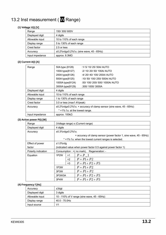
KEW6305 13.2
13.2 Inst measurement ( W Range)
(1) Voltage V(i) [V] Range 150/ 300/ 600V Displayed digit 4 digits Allowable input 10 to 110% of each range Display range 5 to 130% of each range Crest factor 2.5 or less Accuracy ±0.2%rdg±0.2%f.s. (sine wave, 45 - 65Hz) Input impedance approx. 8.3MΩ
(2) Current A(i) [A]
Range 50A type (8128) :1/ 5/ 10/ 25/ 50A/ AUTO 100A type(8127) :2/ 10/ 20/ 50/ 100A/ AUTO 200A type(8126) :4/ 20/ 40/ 100/ 200A/ AUTO 500A type(8125) :10/ 50/ 100/ 250/ 500A/ AUTO 1000A type(8124) :50/ 100/ 200/ 500/ 1000A/ AUTO 3000A type(8129) :300/ 1000/ 3000A
Displayed digit 4 digits Allowable input 10 to 110% of each range Display range 1 to 130% of each range Crest factor 3.0 or less (max1.4Vpeak) Accuracy ±0.2%rdg±0.2%f.s. + accuracy of clamp sensor (sine wave, 45 - 65Hz)
* +1% f.s. at the lowest range. Input impedance approx. 100kΩ
(3) Active power P(i) [W]
Range (Voltage range) x (Current range) Displayed digit 4 digits Accuracy ±0.3%rdg±0.2%f.s.
+ accuracy of clamp sensor (power factor 1, sine wave, 45 - 65Hz) * +1% f.s. when the lowest current ranges is selected.
Effect of power factor
±1.0%rdg (indicated value when power factor 0.5 against power factor 1)
Polarity indication Consumption : +( no mark), Regeneration: - ×1 1_PP = ×2 21 PPP +=
1P2W
×3 321 PPPP ++= 1P3W 21 PPP += 3P3W 21 PPP += 3P3W3A 321 PPPP ++=
Equation
3P4W 321 PPPP ++=
(4) Frequency f [Hz] Accuracy ±3dgt Displayed digit 3 digits Allowable input 10 - 110% of V range (sine wave, 45 - 65Hz) Display range 40.0 - 70.0Hz Input source V1
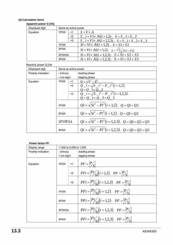
13.3 KEW6305
(5) Calculation items
Apparent power S [VA] Displayed digit Same as active power.
×1 AVS ×= ×2 )2,1(1_ =×= iAiViS , 2_1_ SSS +=
1P2W
×3 )3,2,1(1_ =×= iAiViS , 3_2_1_ SSSS ++= 1P3W )2,1( =×= iAiViSi , 21 SSS += 3P3W )2,1( =×= iAiViSi , ( )212
3 SSS +=
3P3W3A )3,2,1( =×= iAiViSi , 321 SSSS ++=
Equation
3P4W )3,2,1( =×= iAiViSi , 321 SSSS ++=
Reactive power Q [Var Displayed digit Same as active power. Polarity indication - (minus) : leading phase
+ (no sign) : lagging phase ×1 22 PSQ −= ×2 ( )2,1___ 22 =−= iiPiSiQ ,
2_1_ QQQ +=
1P2W
×3 ( )3,2,1___ 22 =−= iiPiSiQ , 3_2_1_ QQQQ ++=
1P3W ( )2,122 =−= iPiSiQi , 21 QQQ +=
3P3W ( )2,122 =−= iPiSiQi , 21 QQQ +=
3P3W3A ( )3,2,122 =−= iPiSiQi , 321 QQQQ ++=
Equation
3P4W ( )3,2,122 =−= iPiSiQi , 321 QQQQ ++=
Power factor PF Display range -1.000 to 0.000 to 1.000 Polarity indication - (minus) : leading phase
+ (no sign) : lagging phase
×1 SPPF =
×2 ( )2,1== iSiPiPFi , S
PPF =
1P2W
×3 ( )3,2,1== iSiPiPFi , S
PPF =
1P3W ( )2,1== iSiPiPFi , S
PPF =
3P3W ( )2,1== iSiPiPFi , S
PPF =
3P3W3A ( )3,2,1== iSiPiPFi , S
PPF =
Equation
3P4W ( )3,2,1== iSiPiPFi , S
PPF =
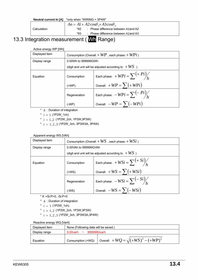
KEW6305 13.4
Neutral current In [A] *only when “WIRING = 3P4W”
Calculation 32 cos3cos21 θθ AAAAn ++=
*θ2 : Phase difference between A1and A2 *θ3 : Phase difference between A1and A3
13.3 Integration measurement ( Wh Range)
Active energy WP [Wh] Displayed item Consumption (Overall: WP+ , each phase: WPi+ )
Display range 0.00Wh to 999999GWh
(digit and unit will be adjusted according to WS+ .)
Consumption
(+WP)
Each phase: ( )∑ +=+ h
PiWPi
Overall: ( )∑ +=+ WPiWP
Equation
Regeneration
(-WP)
Each phase: ( )∑ −=− h
PiWPi
Overall: ( )∑ −=− WPiWP
* h : Duration of integration * 1=i (1P2W_1ch) * 2,1=i (1P2W_2ch, 1P3W,3P3W) * 3,2,1=i (1P2W_3ch, 3P3W3A, 3P4W)
Apparent energy WS [VAh] Displayed item Consumption (Overall: WS+ , each phase: WSi+ )
Display range 0.00VAh to 999999GVAh
(digit and unit will be adjusted according to WS+ )
Consumption
(+WS)
Each phase: ( )∑ +=+ h
SiWSi
Overall: ( )∑ +=+ WSiWS
Equation
Regeneration
(-WS)
Each phase: ( )∑ −=− h
SiWSi
Overall: ( )∑ −=− WSiWS
* if: +Si:P>0, -Si:P<0 * h : Duration of integration * 1=i (1P2W_1ch) * 2,1=i (1P2W_2ch, 1P3W,3P3W) * 3,2,1=i (1P2W_3ch, 3P3W3A,3P4W)
Reactive energy WQ [Varh] Displayed item None (Following data will be saved.) Display range 0.00varh ~ 999999Gvarh
Equation Consumption (+WQ) Overall: 22 )()( WPWSWQ +−+=+
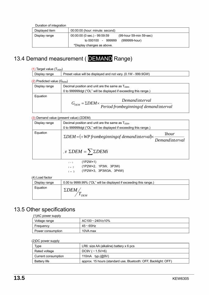
13.5 KEW6305
Duration of integration Displayed item 00:00:00 (hour: minute: second) Display range 00:00:00 (0 sec.) - 99:59:59 (99-hour 59-min 59-sec)
to 000100 - 999999 (999999-hour) *Display changes as above.
13.4 Demand measurement ( DEMAND Range)
(1) Target value (TDEM) Display range Preset value will be displayed and not vary. (0.1W - 999.9GW)
(2) Predicted value (GDEM)
Display range Decimal position and unit are the same as TDEM. 0 to 999999dgt (“OL” will be displayed if exceeding this range.)
Equation
(3) Demand value (present value) (ΣDEM)
Display range Decimal position and unit are the same as TDEM. 0 to 999999dgt (“OL” will be displayed if exceeding this range.)
Equation
, if ∑Σ=Σ DEMiDEM
1=i (1P2W×1) 2=i (1P2W×2,1P3W,3P3W) 3=i (1P2W×3,3P3W3A,3P4W)
(4) Load factor
Display range 0.00 to 9999.99% (“OL” will be displayed if exceeding this range.) Equation
DEMTDEMΣ
13.5 Other specifications (1)AC power supply
Voltage range AC100~240V±10% Frequency 45~65Hz Power consumption 10VA max
(2)DC power supply
Type LR6: size AA (alkaline) battery x 6 pcs Rated voltage DC9V (=1.5V×6) Current consumption 110mA typ.(@9V) Battery life approx. 15 hours (standard use, Bluetooth: OFF, Backlight: OFF)
ervaldemandofbeginningfromPeriodervalDemandDEMGDEM int
int×Σ=
( )ervalDemand
hourervaldemandofbeginningfromWPDEMint
1int ×+=Σ
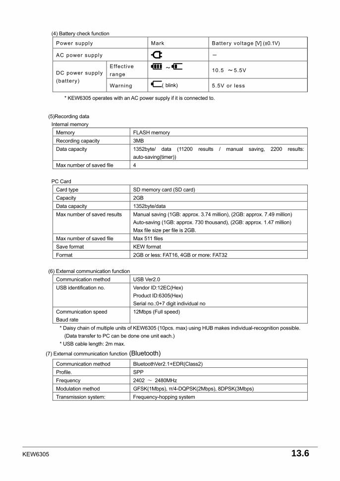
KEW6305 13.6
(4) Battery check function
Power supply Mark Battery voltage [V] (±0.1V)
AC power supply -
Effective range
~ 10.5 ~ 5.5V DC power supply(battery)
Warning ( blink) 5.5V or less
* KEW6305 operates with an AC power supply if it is connected to.
(5)Recording data
Internal memory Memory FLASH memory Recording capacity 3MB Data capacity 1352byte/ data (11200 results / manual saving, 2200 results:
auto-saving(timer)) Max number of saved file 4
PC Card
Card type SD memory card (SD card) Capacity 2GB Data capacity 1352byte/data Max number of saved results
Manual saving (1GB: approx. 3.74 million), (2GB: approx. 7.49 million) Auto-saving (1GB: approx. 730 thousand), (2GB: approx. 1.47 million) Max file size per file is 2GB.
Max number of saved file Max 511 files Save format KEW format Format 2GB or less: FAT16, 4GB or more: FAT32
(6) External communication function
Communication method USB Ver2.0 USB identification no. Vendor ID:12EC(Hex)
Product ID:6305(Hex) Serial no.:0+7 digit individual no
Communication speed Baud rate
12Mbps (Full speed)
* Daisy chain of multiple units of KEW6305 (10pcs. max) using HUB makes individual-recognition possible. (Data transfer to PC can be done one unit each.)
* USB cable length: 2m max.
(7) External communication function (Bluetooth) Communication method BluetoothVer2.1+EDR(Class2) Profile. SPP Frequency 2402 ~ 2480MHz Modulation method GFSK(1Mbps), π/4-DQPSK(2Mbps), 8DPSK(3Mbps) Transmission system: Frequency-hopping system
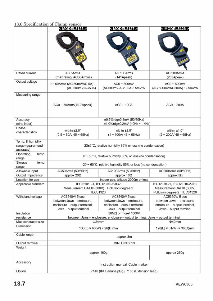
13.7 KEW6305
13.6 Specification of Clamp sensor
< MODEL8128 > < MODEL8127 > < MODEL8126 >
Rated current AC 5Arms (max rating: AC50Armns)
AC 100Arms (141Apeak)
AC 200Arms (283Apeak)
Output voltage 0 ~ 50Arms (AC 50mV/AC 5A)
(AC 500mV/AC50A) AC0 ~ 500mV
(AC500mV/AC100A) : 5mV/A AC0 ~ 500mV
(AC 500mV/AC200A) : 2.5mV/A
Measuring range
AC0 ~ 50Arms(70.7Apeak) AC0 ~ 100A AC0 ~ 200A
Accuracy (sine input)
±0.5%rdg±0.1mV (50/60Hz) ±1.0%rdg±0.2mV (40Hz ~ 1kHz)
Phase characteristics within ±2.0°
(0.5 ~ 50A/ 45 ~ 65Hz) within ±2.0°
(1 ~ 100A/ 45 ~ 65Hz) within ±1.0°
(2 ~ 200A/ 45 ~ 65Hz)
Temp. & humidity range (guaranteed accuracy)
23±5°C, relative humidity 85% or less (no condensation)
Operating temp. range 0 ~ 50°C, relative humidity 85% or less (no condensation)
Storage temp. range -20 ~ 60°C, relative humidity 85% or less (no condensation)
Allowable input AC50Arms (50/60Hz) AC100Arms (50/60Hz) AC200Arms (50/60Hz) Output impedance approx 20Ω approx 10Ω approx 5Ω Location for use indoor use, altitude 2000m or less Applicable standard IEC 61010-1, IEC 61010-2-032
Measurement CAT.III (300V) Pollution degree 2 IEC61326
IEC 61010-1, IEC 61010-2-032 Measurement CAT.III (600V)
Pollution degree 2 IEC61326 Withstand voltage AC3540V/ 5 sec
between Jaws – enclosure, enclosure – output terminal,
Jaws – output terminal
AC3540V/ 5 sec between Jaws – enclosure, enclosure – output terminal,
Jaws – output terminal
AC5350V/ 5 sec between Jaws – enclosure, enclosure – output terminal,
Jaws – output terminal Insulation resistance
50MΩ or more/ 1000V between Jaws – enclosure, enclosure – output terminal, Jaws – output terminal
Max conductor size Φ24mm Φ40mm Dimension 100(L) × 60(W) × 26(D)mm 128(L) × 81(W) × 36(D)mm
Cable length approx 3m
Output terminal MINI DIN 6PIN Weight
approx 160g approx 260g
Accessory Instruction manual, Cable marker
Option 7146 (Φ4 Banana plug), 7185 (Extension lead)
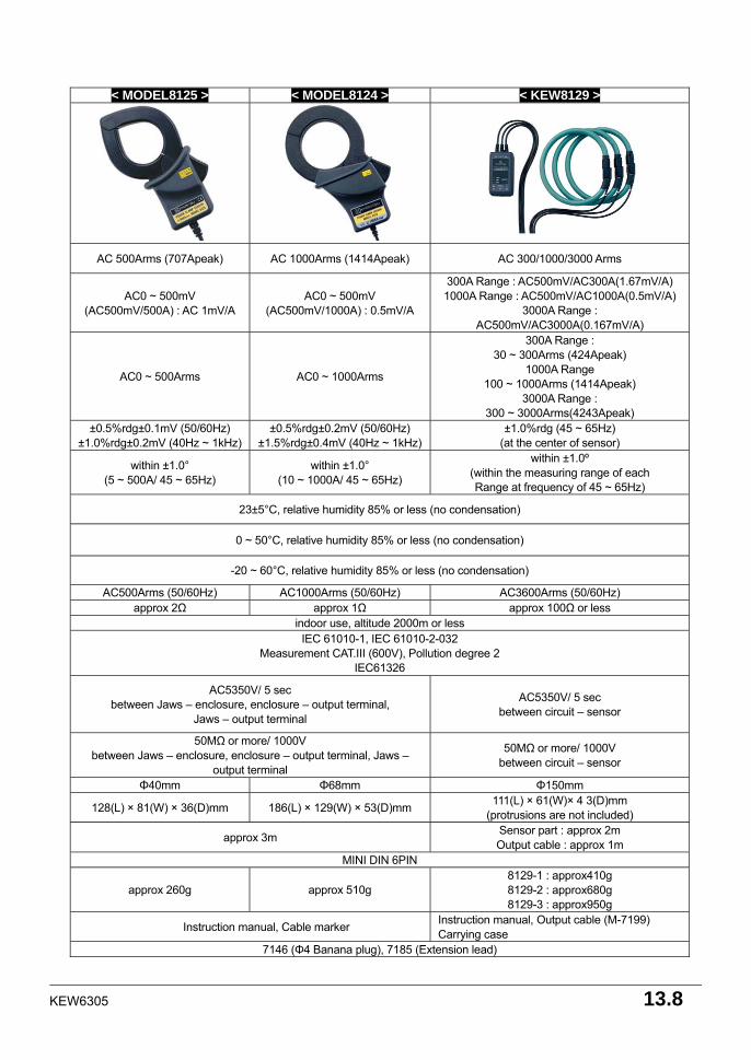
KEW6305 13.8
< MODEL8125 > < MODEL8124 > < KEW8129 >
AC 500Arms (707Apeak) AC 1000Arms (1414Apeak) AC 300/1000/3000 Arms
AC0 ~ 500mV (AC500mV/500A) : AC 1mV/A
AC0 ~ 500mV (AC500mV/1000A) : 0.5mV/A
300A Range : AC500mV/AC300A(1.67mV/A) 1000A Range : AC500mV/AC1000A(0.5mV/A)
3000A Range : AC500mV/AC3000A(0.167mV/A)
AC0 ~ 500Arms AC0 ~ 1000Arms
300A Range : 30 ~ 300Arms (424Apeak)
1000A Range 100 ~ 1000Arms (1414Apeak)
3000A Range : 300 ~ 3000Arms(4243Apeak)
±0.5%rdg±0.1mV (50/60Hz) ±1.0%rdg±0.2mV (40Hz ~ 1kHz)
±0.5%rdg±0.2mV (50/60Hz) ±1.5%rdg±0.4mV (40Hz ~ 1kHz)
±1.0%rdg (45 ~ 65Hz) (at the center of sensor)
within ±1.0° (5 ~ 500A/ 45 ~ 65Hz)
within ±1.0° (10 ~ 1000A/ 45 ~ 65Hz)
within ±1.0º (within the measuring range of each Range at frequency of 45 ~ 65Hz)
23±5°C, relative humidity 85% or less (no condensation)
0 ~ 50°C, relative humidity 85% or less (no condensation)
-20 ~ 60°C, relative humidity 85% or less (no condensation)
AC500Arms (50/60Hz) AC1000Arms (50/60Hz) AC3600Arms (50/60Hz) approx 2Ω approx 1Ω approx 100Ω or less
indoor use, altitude 2000m or less IEC 61010-1, IEC 61010-2-032
Measurement CAT.III (600V), Pollution degree 2 IEC61326
AC5350V/ 5 sec between Jaws – enclosure, enclosure – output terminal,
Jaws – output terminal
AC5350V/ 5 sec between circuit – sensor
50MΩ or more/ 1000V between Jaws – enclosure, enclosure – output terminal, Jaws –
output terminal
50MΩ or more/ 1000V between circuit – sensor
Φ40mm Φ68mm Φ150mm
128(L) × 81(W) × 36(D)mm 186(L) × 129(W) × 53(D)mm 111(L) × 61(W)× 4 3(D)mm (protrusions are not included)
approx 3m Sensor part : approx 2m Output cable : approx 1m
MINI DIN 6PIN
approx 260g approx 510g 8129-1 : approx410g 8129-2 : approx680g 8129-3 : approx950g
Instruction manual, Cable marker Instruction manual, Output cable (M-7199) Carrying case
7146 (Φ4 Banana plug), 7185 (Extension lead)

DISTRIBUTOR
Kyoritsu reserves the rights to change specifications or designs described in this manual without notice and without obligations.
5-12 92-2107