Embed Size (px)
Citation preview
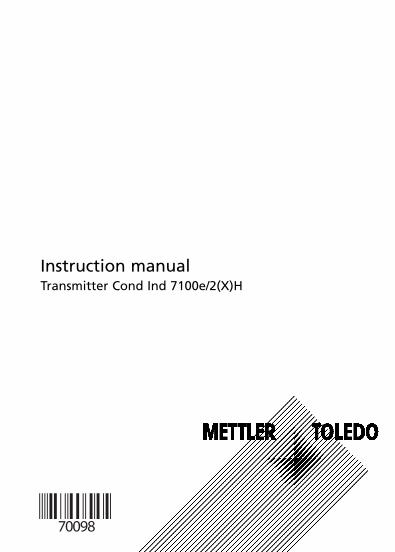
Instruction manualTransmitter Cond Ind 7100e/2(X)H
70098_E_CI7100_2XH.QXD 27.07.2005 9:27 Uhr Seite 1
WarrantyDefects occurring within 1 years from delivery date shall be remedied freeof charge at our plant (carriage and insurance paid by sender).
Subject to change without notice.
Return of products under warantyPlease contact METTLER TOLEDO’s Customer Service Dept. before returninga defective device. Ship the cleaned device to the address you have beengiven. If the device has been in contact with process fluids, it must bedecontaminated/disinfected before shipment. In that case, please attach acorresponding certificate, for the health and safety of our service personnel.
DisposalPlease observe the applicable local or national regulationsconcerning the disposal of “waste electrical and electronicequipment”.
Mettler-Toledo GmbH, Process Analytics, Industrie Nord, CH-8902 Urdorf, Tel. +41 (01) 736 22 11 Fax +41 (01) 736 26 36 Subject to technical changes. Mettler-Toledo GmbH, 10/05. Printed in Germany.
70098_E_CI7100_2XH.QXD 27.07.2005 9:27 Uhr Seite 2
Safety information . . . . . . . . . . . . . . . . . . . . . . . . . . . . . . .5Intended use . . . . . . . . . . . . . . . . . . . . . . . . . . . . . . . . . . . . . . . .7Trademarks . . . . . . . . . . . . . . . . . . . . . . . . . . . . . . . . . . . . . . . . .7
Certificates . . . . . . . . . . . . . . . . . . . . . . . . . . . . . . . . . . . . .8EC Declaration of Conformity . . . . . . . . . . . . . . . . . . . . . . . . . . .8Conformity with FDA 21 CFR Part 11 . . . . . . . . . . . . . . . . . . . . .9EC-Type-Examination Certificate . . . . . . . . . . . . . . . . . . . . . . . .101. Supplement to EC-Type-Examination Certificate . . . . . . . . . .13
Overview of Transmitter . . . . . . . . . . . . . . . . . . . . . . . . . .15
Assembly . . . . . . . . . . . . . . . . . . . . . . . . . . . . . . . . . . . . . . .16Package contents . . . . . . . . . . . . . . . . . . . . . . . . . . . . . . . . . . .16Mounting plan . . . . . . . . . . . . . . . . . . . . . . . . . . . . . . . . . . . . .17Pipe mounting, panel mounting . . . . . . . . . . . . . . . . . . . . . . . .18
Installation and connection . . . . . . . . . . . . . . . . . . . . . . .20Information on installation . . . . . . . . . . . . . . . . . . . . . . . . .20, 22Division 2 wiring . . . . . . . . . . . . . . . . . . . . . . . . . . . . . . . . . . . .20Terminal assignments . . . . . . . . . . . . . . . . . . . . . . . . . . . . . . . .21Wiring examples . . . . . . . . . . . . . . . . . . . . . . . . . . . . . . . . . . . .24
User interface and display . . . . . . . . . . . . . . . . . . . . . . . .26Operation: Keypad . . . . . . . . . . . . . . . . . . . . . . . . . . . . . . . . . .28
Safety features . . . . . . . . . . . . . . . . . . . . . . . . . . . . . . . . .29Sensocheck, Sensoface sensor monitoring . . . . . . . . . . . . . . . .29GainCheck device self test . . . . . . . . . . . . . . . . . . . . . . . . . . . .29Automatic device self-test . . . . . . . . . . . . . . . . . . . . . . . . . . . . .29Hold mode . . . . . . . . . . . . . . . . . . . . . . . . . . . . . . . . . . . . . . .30
Outputs . . . . . . . . . . . . . . . . . . . . . . . . . . . . . . . . . . . . . . . .31(Current output / loop current, HART communication, Alarm) .31
Passcodes (factory setting) . . . . . . . . . . . . . . . . . . . . . . . .32
Configuration . . . . . . . . . . . . . . . . . . . . . . . . . . . . . . . . . . .34Menu structure of configuration . . . . . . . . . . . . . . . . . . . . . . . .35Overview of configuration steps . . . . . . . . . . . . . . . . . . . . . . . .36Individual settings (for copy) . . . . . . . . . . . . . . . . . . . . . . . . . . .37Current output . . . . . . . . . . . . . . . . . . . . . . . . . . . . . . . . . . . . .38
Contents
3
70098_E_CI7100_2XH.QXD 27.07.2005 9:27 Uhr Seite 3
Transmitter Cond Ind 7100e/2(X)
Contents
Temperature compensation . . . . . . . . . . . . . . . . . . . . . . . . . . . .52Alarm settings . . . . . . . . . . . . . . . . . . . . . . . . . . . . . . . . . . . . .54
Passcodes according to FDA 21 CFR Part 11 . . . . . . . . . .56
Calibration . . . . . . . . . . . . . . . . . . . . . . . . . . . . . . . . . . . . .58Calibration by input of cell factor . . . . . . . . . . . . . . . . . . . . . .60Calibration with calibration solution . . . . . . . . . . . . . . . . . . . . .62Product calibration . . . . . . . . . . . . . . . . . . . . . . . . . . . . . . . . . .64Zero calibration in air . . . . . . . . . . . . . . . . . . . . . . . . . . . . . . . .66Zero calibration with calibration solution . . . . . . . . . . . . . . . . .68Temp probe adjustment . . . . . . . . . . . . . . . . . . . . . . . . . . . . . .70
Measurement . . . . . . . . . . . . . . . . . . . . . . . . . . . . . . . . . . .70
Diagnostics functions . . . . . . . . . . . . . . . . . . . . . . . . . . . .71Display of output currents . . . . . . . . . . . . . . . . . . . . . . . . . . . . .71Display of calibration data (Cal nfo) . . . . . . . . . . . . . . . . . . . . .71Sensor monitor . . . . . . . . . . . . . . . . . . . . . . . . . . . . . . . . . . . . .71Display of last error message . . . . . . . . . . . . . . . . . . . . . . . . . .71Specify output current . . . . . . . . . . . . . . . . . . . . . . . . . . . . . . .72
Cleaning . . . . . . . . . . . . . . . . . . . . . . . . . . . . . . . . . . . . . . .72
Operating states . . . . . . . . . . . . . . . . . . . . . . . . . . . . . . . . .73
Error messages (error codes) . . . . . . . . . . . . . . . . . . . . . .74
Sensoface . . . . . . . . . . . . . . . . . . . . . . . . . . . . . . . . . . . . . .76
Appendix . . . . . . . . . . . . . . . . . . . . . . . . . . . . . . . . . . . . . . .79Product line and accessories . . . . . . . . . . . . . . . . . . . . . . . . . . .79Specifications . . . . . . . . . . . . . . . . . . . . . . . . . . . . . . . . . . . . . .80Calibration solutions . . . . . . . . . . . . . . . . . . . . . . . . . . . . . . . . .86Concentration measurement: Ranges . . . . . . . . . . . . . . . . . . . .88Concentration curves . . . . . . . . . . . . . . . . . . . . . . . . . . . . . . . .89FM Control Drawing . . . . . . . . . . . . . . . . . . . . . . . . . . . . . . . . .94Explosion protection . . . . . . . . . . . . . . . . . . . . . . . . . . . . . . . . .96CSA Control Drawing . . . . . . . . . . . . . . . . . . . . . . . . . . . . . . . .98
Index . . . . . . . . . . . . . . . . . . . . . . . . . . . . . . . . . . . . . . . . .101
4
70098_E_CI7100_2XH.QXD 27.07.2005 9:27 Uhr Seite 4
5
Safety information
Be sure to read and observe the following instruc-tions!
The device has been designed using state of the art technolo-gies and it complies with the applicable safety regulations.When operating the device, certain conditions may neverthe-less lead to danger for the operator or damage to the device.
Caution!Commissioning may only be carried out by trained experts.Whenever it is likely that protection has been impaired, thedevice shall be made inoperative and secured against unintend-ed operation.
The protection is likely to be impaired if, for example:• the device shows visible damage• the device fails to perform the intended measurements• after prolonged storage at temperatures above 70 °C• after severe transport stresses
Before recommissioning the device, a professional routine testin accordance with EN 61010-1 must be performed. This testshould be carried out by the manufacturer.
Caution!Before commissioning it must be proved that the device maybe connected with other equipment.
70098_E_CI7100_2XH.QXD 27.07.2005 9:27 Uhr Seite 5
6 Transmitter Cond Ind 7100e/2(X)
Safety precautions for installation
• The stipulations of EN 60079-10 / EN 60079-14 must be observed during commissioning.
• The Transmitter Cond Ind 7100e/2H is approved for measurements in FM Class 1 Div 2.
• The Transmitter Cond Ind 7100e/2XH is approved for operation in the following locations: ATEX, FM Zone 1 withmeasurement in Zone 0, and FM Class I Div 1.
Connection to supply units
• Transmitter Cond Ind 7100e/2H: Before connecting this device to a supply unit, make sure that its output voltage cannot exceed 30 V DC. Do not use alternating current or mains power supply!
• Transmitter Cond Ind 7100e/2XH: This device may only be connected to an explosion-proof power supply unit (for input ratings refer to annex of EC-Type-Examination Certificate). Before commissioning it must be made sure that the connections to other equipment such as power supply unitand cables are intrinsically safe.
Terminals: suitable for single wires / flexible leads up to 2.5 mm2 (AWG 14)
Note for cleaning in a hazardous locationIn hazardous locations the transmitter may only be cleaned witha damp cloth to prevent electrostatic discharge.
Safety information
70098_E_CI7100_2XH.QXD 27.07.2005 9:27 Uhr Seite 6
7
Intended use
The Transmitter Cond Ind 7100e/2(X) is used for measurement ofelectrical conductivity and temperature in liquids in the field ofbiotechnology, chemical and pharmaceutical industry, pulp andpaper, as well as industry, environment, food processing, andsewage treatment. The rugged molded enclosure can be wall or pipe mounted orfixed into a control panel.The protective hood provides additional protection against directweather exposure and mechanical damage. The transmitter has been designed for application with elec-trodeless sensors, particularly for the sensors of the InPro 7250series.
• The Transmitter Cond Ind 7100e/2H is approved for measurements in FM Class 1 Div 2.
• The Transmitter Cond Ind 7100e/2XH is approved for operation in the following locations: ATEX, FM Zone 1 withmeasurement in Zone 0, and FM Class I Div 1.
Trademarks
The following names are registered trademarks. For practical rea-sons they are shown without trademark symbol in this manual.SensofaceSensocheckGainCheck
InPro® is a registered trademark of Mettler-Toledo.HART® is a registered trademark of the HART CommunicationFoundation (HCF).
70098_E_CI7100_2XH.QXD 27.07.2005 9:27 Uhr Seite 7
8 Transmitter Cond Ind 7100e/2(X)
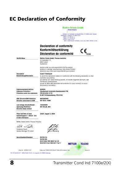
EC Declaration of Conformity
70098_E_CI7100_2XH.QXD 27.07.2005 9:27 Uhr Seite 8
Declaration of conformity Konformitätserklärung Déclaration de conformité 0102
We/Wir/Nous Mettler-Toledo GmbH, Process Analytics Im Hackacker 15 8902 Urdorf Switzerland
declare under our sole responsibility that the product, erklären in alleiniger Verantwortung, dass dieses Produkt, déclarons sous notre seule responsabilité que le produit,
CondI 7100/2(X)H DescriptionBeschreibung/Description to which this declaration relates is in conformity with the following standard(s) or other
normative document(s).auf welches sich diese Erklärung bezieht, mit der/den folgenden Norm(en) oder Richtlinie(n) übereinstimmt. auquel se réfère cette déclaration est conforme à la (aux) norme(s) ou au(x) document(s) normatif(s).
94/9/EG Physikalisch-Technische Bundesanstalt PTB PTB 00 ATEX 2172 D-38116 Braunschweig, PTB 0102
Explosionsschutzrichtlinie Explosion Protection /Protection contre les explosions
89/336/EWG SR 734.5, VEMV
EMC Directive/EMV-RichtlinieDirective concernant la CEM
73/23/EWG SR 734.26, NEV
Low-voltage directve/Nieder-spannungs-Richtlinie/Directive basse tension
Place and Date of issue Ausstellungsort / - Datum Lieu et date d’émission
Urdorf, August 3, 2004
Mettler-Toledo GmbH, Process Analytics
Waldemar Rauch Christian Zwicky General Manager PO Urdorf Head of Marketing
Artikel Nr.: 52960319 KE Dateiname: 52960319KE-CondI7100e-2(X)H-Internet-3.doc Version b
EN 50 014 EN 50 020 EN 61326/ VDE 0843 Teil 20 EN 61010 Teil/ VDE 0411 Teil 1
Norm/Standard/Standard
9
Conformity with FDA 21 CFR Part 11
In their directive “Title 21 Code of Federal Regulations, 21 CFRPart 11, Electronic Records; Electronic Signatures” the USAmerican health agency FDA (Food and Drug Administration)regulates the production and processing of electronic docu-ments for pharmaceutical development and production. Thisresults in requirements for measuring devices used for corre-sponding applications. The following features ensure that themeasuring devices of the Transmitter Cond Ind 7100e/2(X)HSeries meet the demands of FDA 21 CFR Part 11:
Electronic SignatureAccess to the device functions is regulated and limited by indi-vidually adjustable codes – “Passcodes” (for Passcode Editorsee Page 56, overview of factory settings on back of manual).This prevents unauthorized modification of device settings ormanipulation of the measurement results. Appropriate use ofthese passcodes makes them suitable as electronic signature.
Audit TrailEvery (manual) change of device settings can be automaticallydocumented. For that purpose, each change is marked by a“Configuration Change Flag”, which can be interrogated anddocumented via HART communication. Then the changeddevice settings/parameters can also be retrieved and docu-mented via HART communication.
70098_E_CI7100_2XH.QXD 27.07.2005 9:27 Uhr Seite 9
10 Transmitter Cond Ind 7100e/2(X)
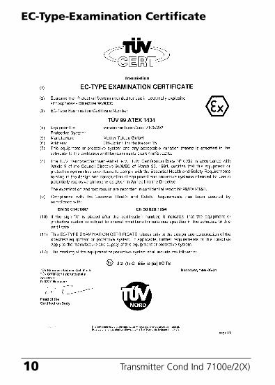
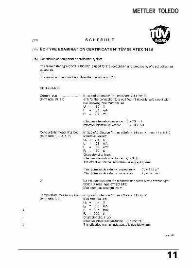
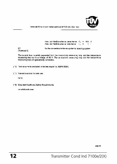
EC-Type-Examination Certificate
70098_E_CI7100_2XH.QXD 27.07.2005 9:27 Uhr Seite 10
11
70098_E_CI7100_2XH.QXD 27.07.2005 9:27 Uhr Seite 11
12 Transmitter Cond Ind 7100e/2(X)
70098_E_CI7100_2XH.QXD 27.07.2005 9:27 Uhr Seite 12
13
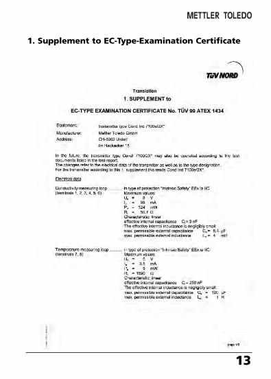
1. Supplement to EC-Type-Examination Certificate
70098_E_CI7100_2XH.QXD 27.07.2005 9:27 Uhr Seite 13
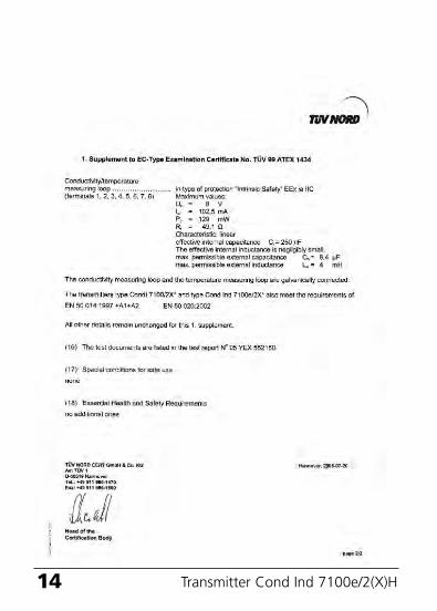
14 Transmitter Cond Ind 7100e/2(X)H
70098_E_CI7100_2XH.QXD 27.07.2005 9:27 Uhr Seite 14
15
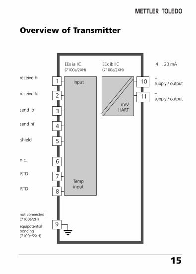
Overview of Transmitter
1
2
3
4
5
6
7
8
Inputreceive hi
receive lo
send lo
send hi
shield
not connected(7100e/2H)
equipotentialbonding(7100e/2XH)
RTD
RTD
Tempinput
10
11
EEx ia IIC(7100e/2XH)
EEx ib IIC(7100e/2XH)
4 ... 20 mA
n.c.
9
mA/HART
+ supply / output
– supply / output
70098_E_CI7100_2XH.QXD 27.07.2005 9:27 Uhr Seite 15
16 Transmitter Cond Ind 7100e/2(X)
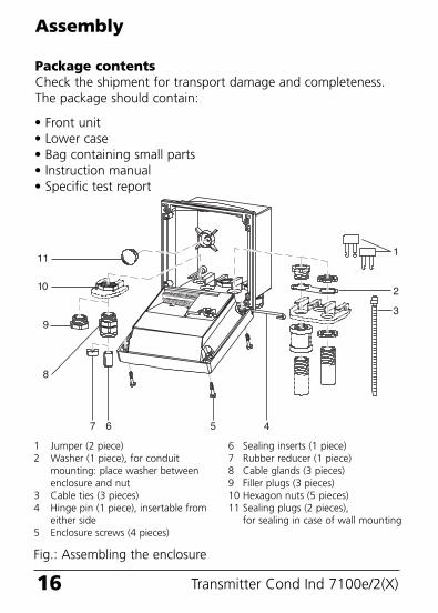
Package contentsCheck the shipment for transport damage and completeness.The package should contain:
Assembly
11
10
9
8
7 6 5 4
1
2
3
6 Sealing inserts (1 piece)7 Rubber reducer (1 piece)8 Cable glands (3 pieces)9 Filler plugs (3 pieces)10 Hexagon nuts (5 pieces)11 Sealing plugs (2 pieces),
for sealing in case of wall mounting
1 Jumper (2 piece)2 Washer (1 piece), for conduit
mounting: place washer between enclosure and nut
3 Cable ties (3 pieces)4 Hinge pin (1 piece), insertable from
either side5 Enclosure screws (4 pieces)
Fig.: Assembling the enclosure
• Front unit • Lower case• Bag containing small parts• Instruction manual• Specific test report
70098_E_CI7100_2XH.QXD 27.07.2005 9:27 Uhr Seite 16
17
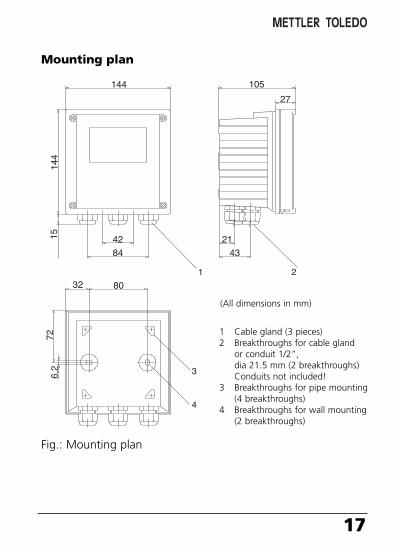
Mounting plan
144
144
15 42
84
8032
21
43
105
27
726,
2
1 2
3
4
1 Cable gland (3 pieces)2 Breakthroughs for cable gland
or conduit 1/2”,dia 21.5 mm (2 breakthroughs)Conduits not included!
3 Breakthroughs for pipe mounting(4 breakthroughs)
4 Breakthroughs for wall mounting(2 breakthroughs)
Fig.: Mounting plan
(All dimensions in mm)
70098_E_CI7100_2XH.QXD 27.07.2005 9:27 Uhr Seite 17
18 Transmitter Cond Ind 7100e/2(X)
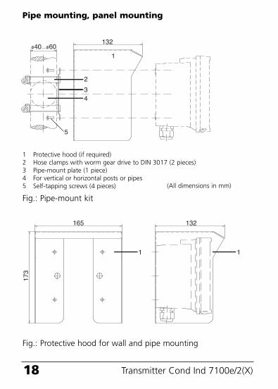
40 60132
1
2
34
5
Fig.: Pipe-mount kit
1 Protective hood (if required)2 Hose clamps with worm gear drive to DIN 3017 (2 pieces)3 Pipe-mount plate (1 piece)4 For vertical or horizontal posts or pipes5 Self-tapping screws (4 pieces)
1
132165
173
1
Fig.: Protective hood for wall and pipe mounting
Pipe mounting, panel mounting
(All dimensions in mm)
70098_E_CI7100_2XH.QXD 27.07.2005 9:27 Uhr Seite 18
19
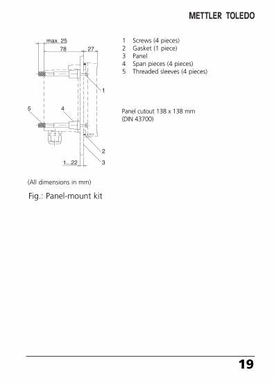
1
2
3
45
max. 2578 27
1...22
1 Screws (4 pieces)2 Gasket (1 piece)3 Panel4 Span pieces (4 pieces)5 Threaded sleeves (4 pieces)
Fig.: Panel-mount kit
Panel cutout 138 x 138 mm(DIN 43700)
(All dimensions in mm)
70098_E_CI7100_2XH.QXD 27.07.2005 9:27 Uhr Seite 19
20 Transmitter Cond Ind 7100e/2(X)
Installation and connection
Information on installation• Installation may only be carried out by trained experts in
accordance with this instruction manual and as per applicable local and national codes.
• Be sure to observe the technical specifications and input ratings.• Be sure not to notch the conductor when stripping the insulation.• When commissioning, a complete configuration must be
carried out by the system administrator.
Connection to supply units• Transmitter Cond Ind 7100e/2H: Before connecting this device
to a supply unit, make sure that its output voltage cannot exceed30 V DC. Do not use alternating current or mains power supply!
• Transmitter Cond Ind 7100e/2XH: This device may only be connected to an explosion-proof power supply unit (for input ratings refer to annex of EC-Type-Examination Certificate).
Terminals: suitable for single wires / flexible leads up to 2.5 mm2
(AWG 14)
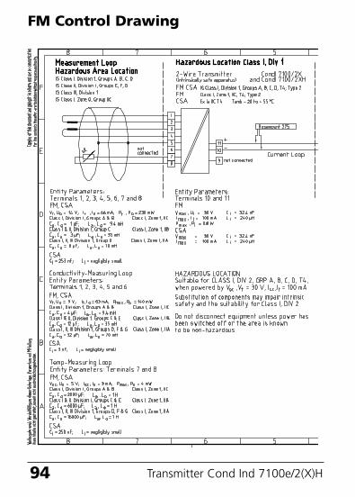
The connections to the transmitter must be installedin accordance with the National Electric Code (ANSI-NFPA 70) Division 2 hazardous (classified) locationnon-incendive wiring techniques.
FM Control Drawing: Refer to page
Division 2 wiring
94.
Warning!Additional safety precautions have to be taken for applications inhazardous locations to CSA!(See Pg 97 et seq.)
70098_E_CI7100_2XH.QXD 27.07.2005 9:27 Uhr Seite 20
21
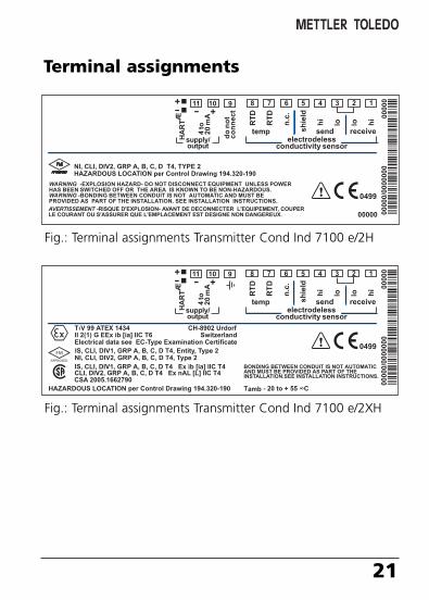
Terminal assignments
Fig.: Terminal assignments Transmitter Cond Ind 7100 e/2H
Fig.: Terminal assignments Transmitter Cond Ind 7100 e/2XH
70098_E_CI7100_2XH.QXD 27.07.2005 9:27 Uhr Seite 21
22 Transmitter Cond Ind 7100e/2(X)H
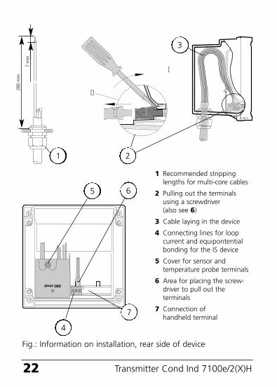
1 Recommended strippinglengths for multi-core cables
2 Pulling out the terminalsusing a screwdriver(also see 6)
3 Cable laying in the device
4 Connecting lines for loop current and equipontential bonding for the IS device
5 Cover for sensor andtemperature probe terminals
6 Area for placing the screw-driver to pull out the terminals
7 Connection of handheld terminal
Fig.: Information on installation, rear side of device
1
2
3
4
65
7 m
m
280
mm
7
70098_E_CI7100_2XH.QXD 27.07.2005 9:27 Uhr Seite 22

23
70098_E_CI7100_2XH.QXD 27.07.2005 9:27 Uhr Seite 23
Transmitter Cond Ind 7100e/2(X)24
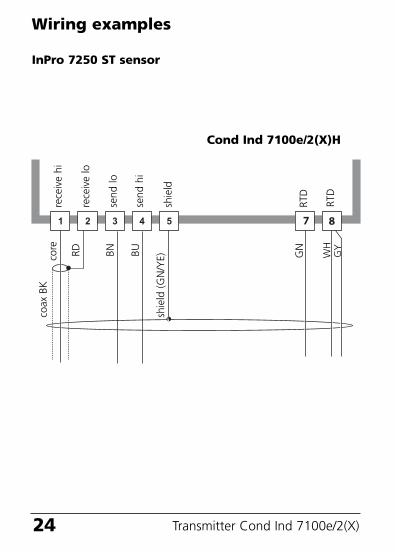
Wiring examples
InPro 7250 ST sensorre
ceiv
e hi
rece
ive
lo
shie
ld
RTD
core
RD BN BU
shie
ld (
GN
/YE) W
H
coax
BK
GN
send
lo
send
hi
Cond Ind 7100e/2(X)H
GY
RTD
70098_E_CI7100_2XH.QXD 27.07.2005 9:27 Uhr Seite 24
25
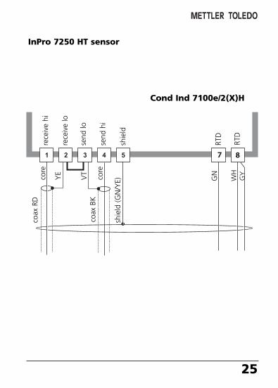
InPro 7250 HT sensorre
ceiv
e hi
rece
ive
lo
shie
ld
RTD
core
YE
VT
core
shie
ld (
GN
/YE) W
H
coax
RD
coax
BK
GN
send
lo
send
hi
Cond Ind 7100e/2(X)H
GY
RTD
70098_E_CI7100_2XH.QXD 27.07.2005 9:27 Uhr Seite 25
26 Transmitter Cond Ind 7100e/2(X)
User interface and display
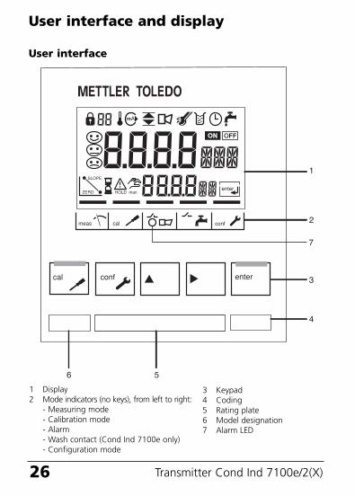
1 Display2 Mode indicators (no keys), from left to right:
- Measuring mode- Calibration mode- Alarm- Wash contact (Cond Ind 7100e only)- Configuration mode
User interface
3 Keypad4 Coding5 Rating plate6 Model designation7 Alarm LED
70098_E_CI7100_2XH.QXD 27.07.2005 9:27 Uhr Seite 26
27
1 2 3 4 5 6 7 8 9 10
11
12
13
1617
20
18
19
15 14
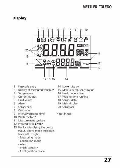
1 Passcode entry2 Display of measured variable*3 Temperature4 Current output5 Limit values6 Alarm7 Sensocheck8 Calibration9 Interval/response time10 Wash contact*11 Measurement symbols12 Proceed with enter13 Bar for identifying the device
status, above mode indicatorsfrom left to right:- Measuring mode- Calibration mode- Alarm- Wash contact*- Configuration mode
14 Lower display15 Manual temp specification16 Hold mode active17 Waiting time running18 Sensor data19 Main display20 Sensoface
* Not in use
Display
70098_E_CI7100_2XH.QXD 27.07.2005 9:27 Uhr Seite 27
28 Transmitter Cond Ind 7100e/2(X)
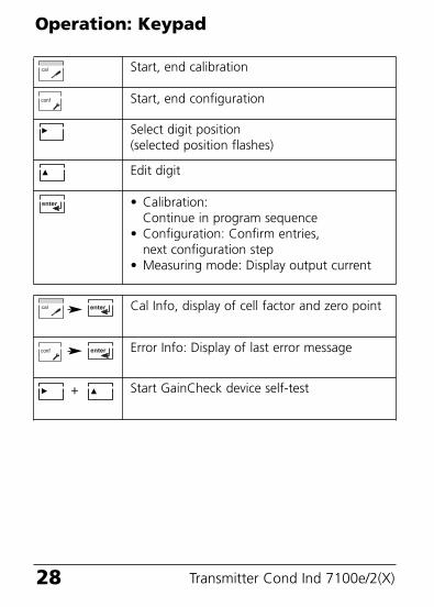
Operation: Keypad
Start, end calibration
Start, end configuration
Select digit position(selected position flashes)
Edit digit
• Calibration: Continue in program sequence
• Configuration: Confirm entries,next configuration step
• Measuring mode: Display output current
Cal Info, display of cell factor and zero point
Error Info: Display of last error message
Start GainCheck device self-test+
70098_E_CI7100_2XH.QXD 27.07.2005 9:27 Uhr Seite 28
29
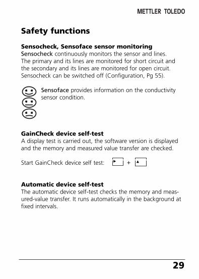
Safety functions
Sensocheck, Sensoface sensor monitoringSensocheck continuously monitors the sensor and lines. The primary and its lines are monitored for short circuit andthe secondary and its lines are monitored for open circuit. Sensocheck can be switched off (Configuration, Pg 55).
Sensoface provides information on the conductivitysensor condition.
GainCheck device self-testA display test is carried out, the software version is displayedand the memory and measured value transfer are checked.
Start GainCheck device self test:
Automatic device self-testThe automatic device self-test checks the memory and meas-ured-value transfer. It runs automatically in the background atfixed intervals.
+
70098_E_CI7100_2XH.QXD 27.07.2005 9:27 Uhr Seite 29
30 Transmitter Cond Ind 7100e/2(X)
Safety functions
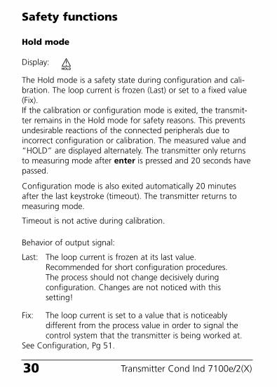
Hold mode
Display:
The Hold mode is a safety state during configuration and cali-bration. The loop current is frozen (Last) or set to a fixed value(Fix).If the calibration or configuration mode is exited, the transmit-ter remains in the Hold mode for safety reasons. This preventsundesirable reactions of the connected peripherals due toincorrect configuration or calibration. The measured value and“HOLD” are displayed alternately. The transmitter only returnsto measuring mode after enter is pressed and 20 seconds havepassed.
Configuration mode is also exited automatically 20 minutesafter the last keystroke (timeout). The transmitter returns tomeasuring mode.
Timeout is not active during calibration.
Behavior of output signal:
Last: The loop current is frozen at its last value.Recommended for short configuration procedures.The process should not change decisively during configuration. Changes are not noticed with thissetting!
Fix: The loop current is set to a value that is noticeablydifferent from the process value in order to signal thecontrol system that the transmitter is being worked at.
See Configuration, Pg 51.
70098_E_CI7100_2XH.QXD 27.07.2005 9:27 Uhr Seite 30
31
Outputs
Current output / Loop currentThe loop current is controlled by the process variable selectedin the configuration.The current start and end can be set to represent any desiredvalue. To check connected peripherals (e.g. limit switches, controllers), the loop current can be manually specified (see Pg. 41).
HART communicationThe Transmitter Cond Ind 7100e/2(X) can be remote-controlledvia HART communication. It can be configured using a hand-held terminal or from the control room. Measured values, mes-sages and device identification can be downloaded at any time.This allows easy integration also in fully automatic processcycles.
A list of the HART commands can be found in the “TransmitterCond Ind 7100e/2(X) Transmitter-Specific CommandSpecification”: www.mtpro.com/transmitters.
AlarmThe alarm delay is configurable.Error messages can also be signaled by a 22 mA loop current(see Configuration, Pg 55).
The alarm LED on the front panel can be configured as follows:HOLD off: Alarm: LED flashingHOLD on: Alarm: LED on. HOLD: LED flashing.
70098_E_CI7100_2XH.QXD 27.07.2005 9:27 Uhr Seite 31
32 Transmitter Cond Ind 7100e/2(X)H
70098_E_CI7100_2XH.QXD 27.07.2005 9:27 Uhr Seite 32
33
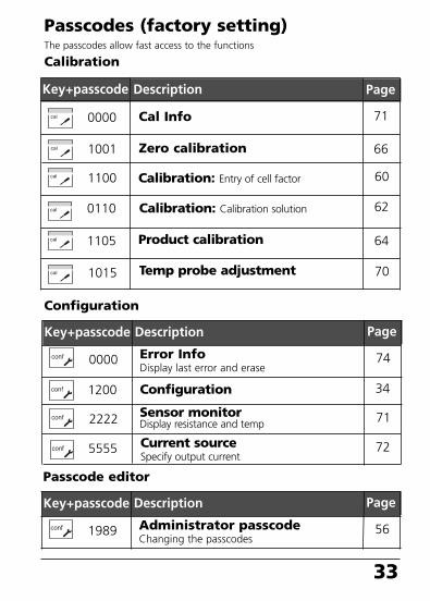
Passcodes (factory setting)The passcodes allow fast access to the functions
Calibration
Key+passcode Description
Cal Info0000
1100
Product calibration1105
Temp probe adjustment1015
Configuration
Error InfoDisplay last error and erase
0000
Configuration
Sensor monitorDisplay resistance and temp
1200
2222
Key+passcode Description
Calibration: Calibration solution0110
5555 Current sourceSpecify output current
Calibration: Entry of cell factor
71
60
64
70
74
34
71
62
72
Page
Page
Passcode editor
Administrator passcodeChanging the passcodes
1989
Key+passcode Description
56
Page
Zero calibration1001 66
70098_E_CI7100_2XH.QXD 27.07.2005 9:27 Uhr Seite 33
34 Transmitter Cond Ind 7100e/2(X)
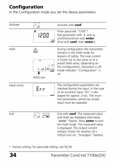
ConfigurationIn the Configuration mode you set the device parameters.
Activate with conf
Enter passcode “1200”*. Edit parameter with and ,confirm/continue with enter.(End with conf, then enter.)
During configuration the transmitterremains in the Hold mode forreasons of safety. The loop currentis frozen (at its last value or at apreset fixed value, depending onthe configuration), Sensoface is off,mode indicator “Configuration” ison.
Activate
Hold
Input errors The configuration parameters arechecked during the input. In the caseof an incorrect input ”Err” is dis-played for approx. 3 sec. The incor-rect parameters cannot be stored.Input must be repeated.
End End with conf. The measured valueand Hold are displayed alternately,“enter” flashes. Press enter to endthe Hold mode. The measured valueis displayed. The output currentremains frozen for another 20 s(HOLD icon on, “hourglass” flashes).
HOLD icon
* Factory setting, for passcode editing, see Pg 56
70098_E_CI7100_2XH.QXD 27.07.2005 9:27 Uhr Seite 34
35
Menu group Code
Current output o1.
Temperature compensation
tc.
Alarmsettings
AL.
DisplaySelect menu group
Previous menugroup:
Menu structure of configuration
Menu item 1
Menu item 2
Menu item ...
The configuration steps are assigned to different menu groups:• Current output (code: o1.)• Temperature compensation (code: tc.)• Alarm settings (code: AL.)With the arrow keys you can jump between the individual menu groups.Each menu group contains menu items for setting the parameters.
Select menu item
Pressing enter accesses the submenus. The values are edited using thearrow keys. Pressing enter confirms/stores the settings. Return to measurement: Press conf. Press enter to confirm safety prompt.After 20 sec the transmitter will be in measuring mode again.
Example: “o1.” is displayed with all menu items of the“Current output” menu group.
70098_E_CI7100_2XH.QXD 27.07.2005 9:27 Uhr Seite 35
36 Transmitter Cond Ind 7100e/2(X)
Overview of configuration steps
7250 IPR, Other
mS/cm, S/m, SAL, %
LIN / LOG
tc.UnIT Select temperature unit °C / °F
Select temperature compensation(not for SAL)
OFF/LIN/NLF (natural waters)
Lin: Enter temperature coefficient xx.xx %/K (02.00 %/K)
tc Temperature compensation
MenuCode
out1 Current output
o1.SnSR Sensor selection
Select measured variable
Select solutionCodes: -01- to —10- see Pg 42
Characteristic linear / logarithmic(not for SAL, Conc)
Selection / Default
ALrt Alarm settings
AL.SnSO Select Sensocheck ON / OFFEnter alarm delay 0000 ... 0600 SEC (0010 SEC)LED in HOLD mode ON / OFF
(Factory setting bold print)
o1.4mA
o1.20mA
o1.4mA
o1.UnIT
o1.CoNC
o1.CHAR
o1.20mA
tc.
tc.lin
AL.dLY
AL.LED
NaCl
-01-
Fix:
Time constant of output filter xxxx SEC (0000 SEC)22 mA signal for error messages ON / OFFSignal behavior during HOLD Last / Fix
Enter fixed value xxx.x mA (021.0 mA)
xxxx mS (000.0 mS)Enter current end
LOG: Enter current start
Enter current end
xxxx mS (000.0 mS)in decades: 0.001 ... 1000 mS(0.100 mS)
in decades: 0.001 ... 1000 mS(100.0 mS)
LIN: Enter current start
o1.FtME
o1.FAIL
o1.HoLD
o1.FIX
Codes -02- ... -10-
o1.CELL
Only with Other:
Entry of cell factor
Enter transfer ratio
Select temperature probe
2.175 (00.100...20.000)
120.00 (001.00...200.00)
Pt100/Pt1000/NTC100/NTC30
o1.SFC
o1.rTD
70098_E_CI7100_2XH.QXD 27.07.2005 9:27 Uhr Seite 36
Code Parameter Default Individualsettings settings
o1.SnSR Sensor selection 7250 IPR ____________
- With “Other” selected:
- Cell factor 2.175 ____________
- Transfer ratio 120.00 ____________
- Temperature probe Pt 1000 ____________
o1.UnIT Measurement unit 000.0 mS/cm ____________
o1.CoNC Concentration NaCl ____________
o1.CHAR Characteristic (LIN/LOG)LIN ____________
o1.4mA Current start 000.0 mS ____________
o1.20mA Current end 100.0 mS ____________
o1.FtME Filter time 0000 SEC ____________
o1.FAIL 22mA signal OFF ____________
o1.HoLD Hold behavior LAST ____________
o1.FIX Fix current 021.0 mA ____________
tc.UnIT Unit °C / °F °C ____________
tc. Temp.compensation OFF ____________
tc.LIN TC process medium 02.00 %/K ____________
AL.SnSO Sensocheck OFF ____________
AL.dLY Alarm delay 0010 SEC ____________
AL.LED LED in Hold mode OFF ____________
37
Individual settings(Original for copy)
70098_E_CI7100_2XH.QXD 27.07.2005 9:27 Uhr Seite 37
38 Transmitter Cond Ind 7100e/2(X)
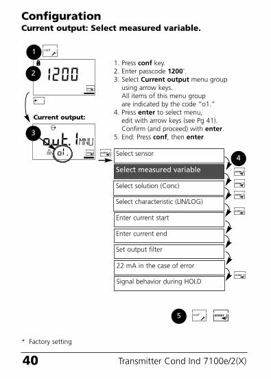
ConfigurationCurrent output: Select sensor type.
Select sensor
Select measured variable
Enter current start
Enter current end
Set output filter
1. Press conf key.2. Enter passcode 1200*.3. Select Current output menu group
using arrow keys. All items of this menu group are indicated by the code “o1.”
4. Press enter to select menu,edit with arrow keys (see Pg 39).Confirm (and proceed) with enter.
5. End: Press conf, then enter
2
3
4
Current output:
22 mA in the case of error
Signal behavior during HOLD
1
5
Select solution (Conc)
Select characteristic (LIN/LOG)
* Factory setting, for passcode editing, see Pg 56
70098_E_CI7100_2XH.QXD 27.07.2005 9:27 Uhr Seite 38
7250 IPR(Other)
39
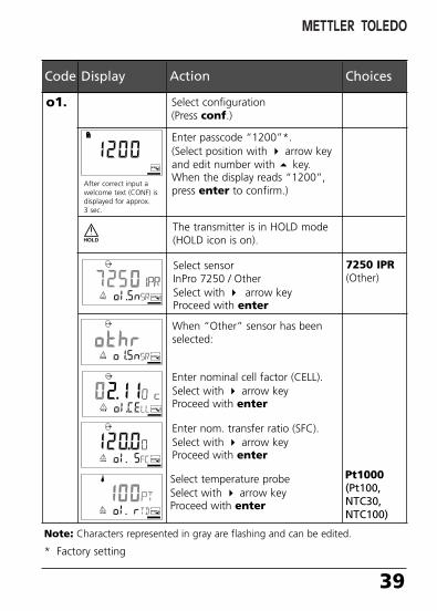
Note:: Characters represented in gray are flashing and can be edited.
Code Display Action Choices
o1. Select configuration(Press conf.)
Enter passcode “1200”*.(Select position with arrow keyand edit number with key.When the display reads “1200”,press enter to confirm.)
The transmitter is in HOLD mode(HOLD icon is on).
Select sensorInPro 7250 / OtherSelect with arrow key Proceed with enter
After correct input awelcome text (CONF) isdisplayed for approx.3 sec.
* Factory setting
When “Other” sensor has beenselected:
Select temperature probeSelect with arrow keyProceed with enter
Pt1000(Pt100,NTC30, NTC100)
Enter nominal cell factor (CELL).Select with arrow key Proceed with enter
Enter nom. transfer ratio (SFC).Select with arrow key Proceed with enter
70098_E_CI7100_2XH.QXD 27.07.2005 9:27 Uhr Seite 39
40 Transmitter Cond Ind 7100e/2(X)
ConfigurationCurrent output: Select measured variable.
Select sensor
Select measured variable
Enter current start
Enter current end
Set output filter
1. Press conf key.2. Enter passcode 1200*.3. Select Current output menu group
using arrow keys. All items of this menu group are indicated by the code “o1.”
4. Press enter to select menu,edit with arrow keys (see Pg 41).Confirm (and proceed) with enter.
5. End: Press conf, then enter
2
3
4
Current output:
22 mA in the case of error
Signal behavior during HOLD
1
5
Select solution (Conc)
Select characteristic (LIN/LOG)
* Factory setting
70098_E_CI7100_2XH.QXD 27.07.2005 9:27 Uhr Seite 40
41
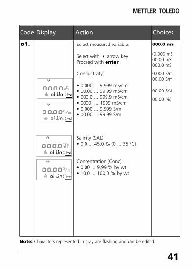
Code Display Action Choices
o1. Select measured variable:
Select with arrow keyProceed with enter
Conductivity:
• 0.000 ... 9.999 mS/cm• 00.00 ... 99.99 mS/cm• 000.0 ... 999.9 mS/cm• 0000 ... 1999 mS/cm• 0.000 ... 9.999 S/m• 00.00 ... 99.99 S/m
Salinity (SAL):• 0.0 ... 45.0 ‰ (0 ... 35 °C)
Concentration (Conc):• 0.00 ... 9.99 % by wt• 10.0 ... 100.0 % by wt
000.0 mS
(0.000 mS00.00 mS000.0 mS
0.000 S/m00.00 S/m
00.00 SAL
00.00 %)
Note:: Characters represented in gray are flashing and can be edited.
70098_E_CI7100_2XH.QXD 27.07.2005 9:27 Uhr Seite 41
42 Transmitter Cond Ind 7100e/2(X)
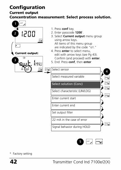
ConfigurationCurrent outputConcentration measurement: Select process solution.
Select sensor
Select measured variable
Enter current start
Enter current end
Set output filter
1. Press conf key.2. Enter passcode 1200*.3. Select Current output menu group
using arrow keys. All items of this menu group are indicated by the code “o1.”
4. Press enter to select menu,edit with arrow keys (see Pg 43).Confirm (and proceed) with enter.
5. End: Press conf, then enter
2
3
4
Current output:
22 mA in the case of error
Signal behavior during HOLD
1
5
Select solution (Conc)
Select characteristic (LIN/LOG)
* Factory setting
70098_E_CI7100_2XH.QXD 27.07.2005 9:27 Uhr Seite 42
43
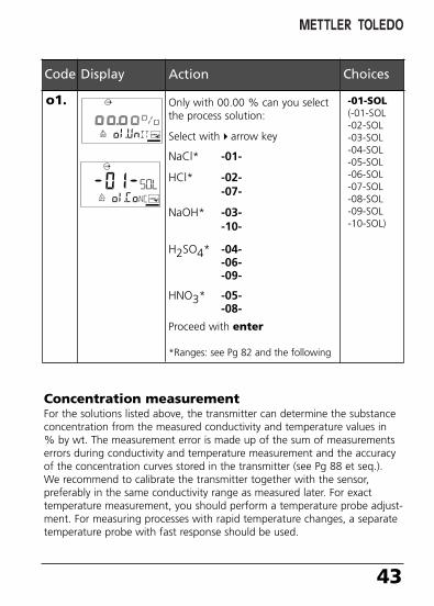
Code Display Action Choices
o1. Only with 00.00 % can you selectthe process solution:
Select witharrow key
NaCl* -01-
HCl* -02--07-
NaOH* -03--10-
H2SO4* -04--06--09-
HNO3* -05--08-
Proceed with enter
*Ranges: see Pg 82 and the following
-01-SOL(-01-SOL-02-SOL-03-SOL-04-SOL-05-SOL-06-SOL-07-SOL-08-SOL-09-SOL-10-SOL)
Concentration measurementFor the solutions listed above, the transmitter can determine the substanceconcentration from the measured conductivity and temperature values in% by wt. The measurement error is made up of the sum of measurementserrors during conductivity and temperature measurement and the accuracyof the concentration curves stored in the transmitter (see Pg 88 et seq.). We recommend to calibrate the transmitter together with the sensor, preferably in the same conductivity range as measured later. For exacttemperature measurement, you should perform a temperature probe adjust-ment. For measuring processes with rapid temperature changes, a separatetemperature probe with fast response should be used.
70098_E_CI7100_2XH.QXD 27.07.2005 9:27 Uhr Seite 43
44 Transmitter Cond Ind 7100e/2(X)
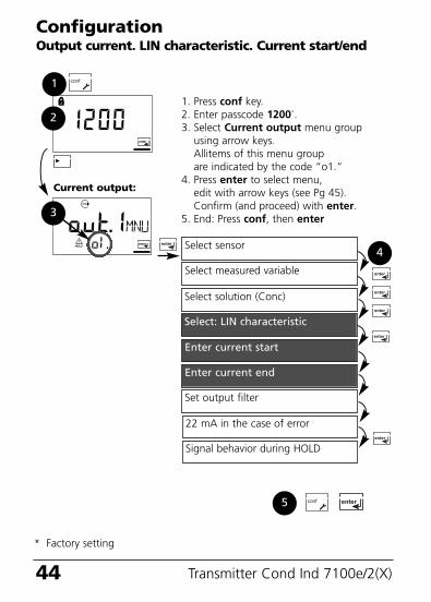
ConfigurationOutput current. LIN characteristic. Current start/end
Select sensor
Select measured variable
Enter current start
Enter current end
Set output filter
1. Press conf key.2. Enter passcode 1200*.3. Select Current output menu group
using arrow keys. Allitems of this menu group are indicated by the code “o1.”
4. Press enter to select menu,edit with arrow keys (see Pg 45).Confirm (and proceed) with enter.
5. End: Press conf, then enter
2
3
4
Current output:
22 mA in the case of error
Signal behavior during HOLD
1
5
Select solution (Conc)
Select: LIN characteristic
* Factory setting
70098_E_CI7100_2XH.QXD 27.07.2005 9:27 Uhr Seite 44
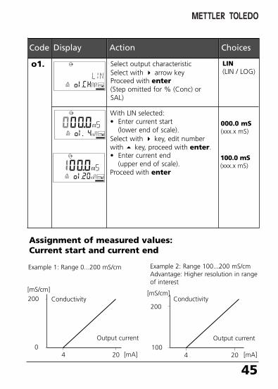
45
Code
LIN(LIN / LOG)
Display Action Choices
o1. Select output characteristicSelect with arrow keyProceed with enter(Step omitted for % (Conc) orSAL)
000.0 mS(xxx.x mS)
100.0 mS(xxx.x mS)
Conductivity
[mS/cm]
204
200
0
Assignment of measured values: Current start and current end
[mS/cm]
204
200
100[mA]
Example 1: Range 0...200 mS/cm Example 2: Range 100...200 mS/cmAdvantage: Higher resolution in rangeof interest
[mA]
Output current
Conductivity
With LIN selected:• Enter current start
(lower end of scale).Select with key, edit numberwith key, proceed with enter.• Enter current end
(upper end of scale). Proceed with enter
Output current
70098_E_CI7100_2XH.QXD 27.07.2005 9:27 Uhr Seite 45

46 Transmitter Cond Ind 7100e/2(X)
ConfigurationOutput current. LOG characteristic. Current start / end
Select sensor
Select measured variable
Enter current start
Enter current end
Set output filter
1. Press conf key.2. Enter passcode 1200*.3. Select Current output menu group
using arrow keys. All items of this menu group are indicated by the code “o1.”
4. Press enter to select menu,edit with arrow keys (see Pg 47).Confirm (and proceed) with enter.
5. End: Press conf, then enter
2
3
4
Current output:
22 mA in the case of error
Signal behavior during HOLD
1
5
Select solution (Conc)
Select: LOG characteristic
* Factory setting
70098_E_CI7100_2XH.QXD 27.07.2005 9:27 Uhr Seite 46
47
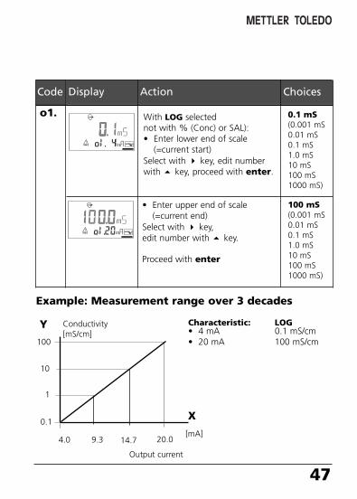
Code Display Action Choices
o1. With LOG selectednot with % (Conc) or SAL):• Enter lower end of scale
(=current start)Select with key, edit numberwith key, proceed with enter.
0.1 mS(0.001 mS0.01 mS0.1 mS1.0 mS10 mS100 mS1000 mS)
100 mS(0.001 mS0.01 mS0.1 mS1.0 mS10 mS100 mS1000 mS)
• Enter upper end of scale (=current end)
Select with key, edit number with key.
Proceed with enter
Example: Measurement range over 3 decades
Characteristic: LOG• 4 mA 0.1 mS/cm• 20 mA 100 mS/cm
[mA]
100
4.0
Output current
Y
X
Conductivity[mS/cm]
20.09.3 14.7
1
10
0.1
70098_E_CI7100_2XH.QXD 27.07.2005 9:27 Uhr Seite 47
48 Transmitter Cond Ind 7100e/2(X)
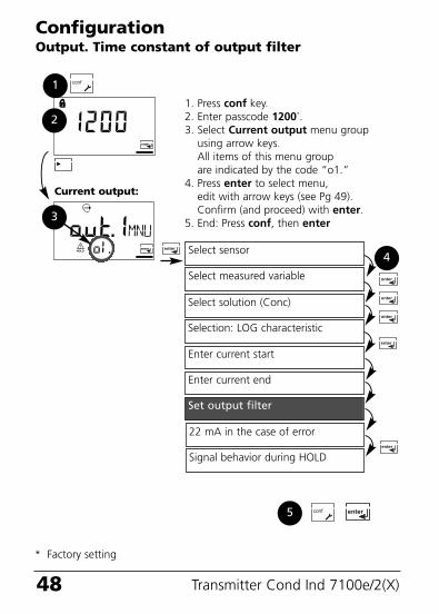
ConfigurationOutput. Time constant of output filter
Select sensor
Select measured variable
Enter current start
Enter current end
Set output filter
1. Press conf key.2. Enter passcode 1200*.3. Select Current output menu group
using arrow keys. All items of this menu group are indicated by the code “o1.”
4. Press enter to select menu,edit with arrow keys (see Pg 49).Confirm (and proceed) with enter.
5. End: Press conf, then enter
2
3
4
Current output:
22 mA in the case of error
Signal behavior during HOLD
1
5
Select solution (Conc)
Selection: LOG characteristic
* Factory setting
70098_E_CI7100_2XH.QXD 27.07.2005 9:27 Uhr Seite 48
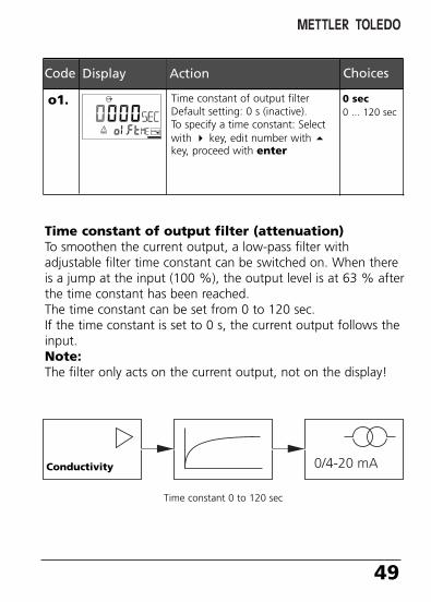
49
0 sec0 ... 120 sec
Code Display Action Choices
o1. Time constant of output filterDefault setting: 0 s (inactive).To specify a time constant: Selectwith key, edit number with key, proceed with enter
Time constant of output filter (attenuation)To smoothen the current output, a low-pass filter withadjustable filter time constant can be switched on. When thereis a jump at the input (100 %), the output level is at 63 % afterthe time constant has been reached.The time constant can be set from 0 to 120 sec.If the time constant is set to 0 s, the current output follows theinput. Note:The filter only acts on the current output, not on the display!
Time constant 0 to 120 sec
Conductivity
70098_E_CI7100_2XH.QXD 27.07.2005 9:27 Uhr Seite 49
50 Transmitter Cond Ind 7100e/2(X)
ConfigurationOutput. Output current during Error and HOLD.
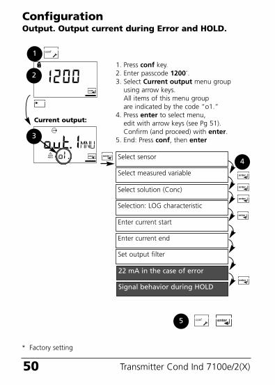
Select sensor
Select measured variable
Enter current start
Enter current end
Set output filter
1. Press conf key.2. Enter passcode 1200*.3. Select Current output menu group
using arrow keys. All items of this menu group are indicated by the code “o1.”
4. Press enter to select menu,edit with arrow keys (see Pg 51).Confirm (and proceed) with enter.
5. End: Press conf, then enter
2
3
4
Current output:
22 mA in the case of error
Signal behavior during HOLD
1
5
Select solution (Conc)
Selection: LOG characteristic
* Factory setting
70098_E_CI7100_2XH.QXD 27.07.2005 9:27 Uhr Seite 50
51
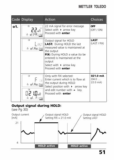
OFF (OFF / ON)
Code Display Action Choices
o1. 22 mA signal for error messageSelect with arrow keyProceed with enter
Output signal for HOLDLAST: During HOLD the lastmeasured value is maintained atthe outputFIX: During HOLD a value (to beentered) is maintained at theoutputSelect with arrow keyProceed with enter
LAST(LAST / FIX)
Only with FIX selected:Enter current which is to flow atthe output during HOLDSelect position with arrow keyand edit number with key.Proceed with enter
021.0 mA(04.0 ...22.0 mA)
Output signal during HOLD:(see Pg 30)Output current[mA]
Output signal HOLDSetting FIX = 21.0 mA
HOLD active
21
4
Output signal HOLDSetting LAST
HOLD active
70098_E_CI7100_2XH.QXD 27.07.2005 9:27 Uhr Seite 51
52 Transmitter Cond Ind 7100e/2(X)
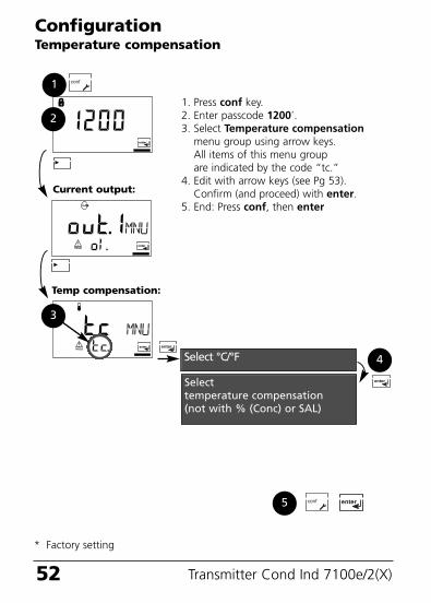
ConfigurationTemperature compensation
1. Press conf key.2. Enter passcode 1200*.3. Select Temperature compensation
menu group using arrow keys. All items of this menu group are indicated by the code “tc.”
4. Edit with arrow keys (see Pg 53).Confirm (and proceed) with enter.
5. End: Press conf, then enter
2
3
4
Temp compensation:
Selecttemperature compensation(not with % (Conc) or SAL)
1
5
Current output:
Select °C/°F
* Factory setting
70098_E_CI7100_2XH.QXD 27.07.2005 9:27 Uhr Seite 52
53
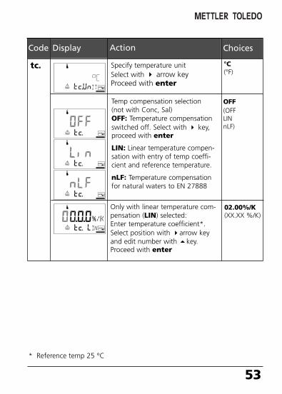
OFF(OFFLINnLF)
Code Display Action Choices
tc.
Only with linear temperature com-pensation (LIN) selected:Enter temperature coefficient*.Select position with arrow keyand edit number with key.Proceed with enter
02.00%/K(XX.XX %/K)
Temp compensation selection(not with Conc, Sal)OFF: Temperature compensationswitched off. Select with key,proceed with enter
LIN: Linear temperature compen-sation with entry of temp coeffi-cient and reference temperature.
nLF: Temperature compensationfor natural waters to EN 27888
°C(°F)
Specify temperature unitSelect with arrow keyProceed with enter
* Reference temp 25 °C
70098_E_CI7100_2XH.QXD 27.07.2005 9:27 Uhr Seite 53
54 Transmitter Cond Ind 7100e/2(X)
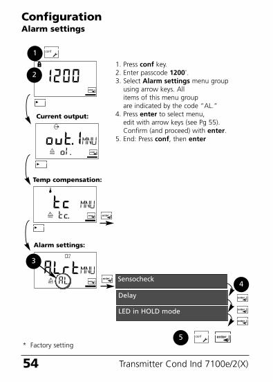
ConfigurationAlarm settings
1. Press conf key.2. Enter passcode 1200*.3. Select Alarm settings menu group
using arrow keys. All items of this menu group are indicated by the code “AL.”
4. Press enter to select menu,edit with arrow keys (see Pg 55).Confirm (and proceed) with enter.
5. End: Press conf, then enter
2
Current output:
1
5
3
Alarm settings:
Sensocheck4
Delay
LED in HOLD mode
Temp compensation:
* Factory setting
70098_E_CI7100_2XH.QXD 27.07.2005 9:27 Uhr Seite 54
55
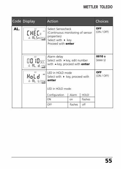
Code Display Action Choices
OFF (ON / OFF)
AL. Select Sensocheck(Continuous monitoring of sensorproperties)Select with key.Proceed with enter
Alarm delay Select with key, edit numberwith key, proceed with enter
0010 s(xxxx s)
LED in HOLD modeSelect with key, proceed withenter
OFF(ON / OFF)
Configuration Alarm HOLD
ON on flashes
OFF flashes off
LED in HOLD mode:
70098_E_CI7100_2XH.QXD 27.07.2005 9:27 Uhr Seite 55
56 Transmitter Cond Ind 7100e/2(X)
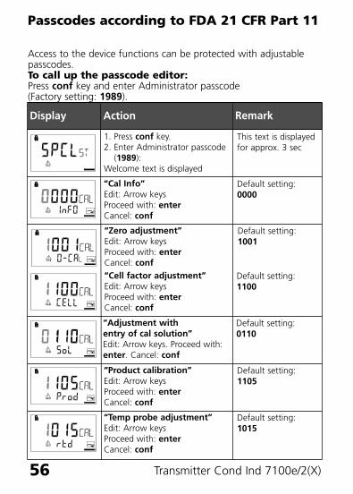
Passcodes according to FDA 21 CFR Part 11
Access to the device functions can be protected with adjustablepasscodes. To call up the passcode editor:Press conf key and enter Administrator passcode(Factory setting: 1989).
Display Action Remark
1. Press conf key.2. Enter Administrator passcode
(1989):Welcome text is displayed
This text is displayedfor approx. 3 sec
“Cal Info”Edit: Arrow keysProceed with: enterCancel: conf
Default setting:0000
“Zero adjustment”Edit: Arrow keysProceed with: enterCancel: conf
Default setting:1001
“Product calibration”Edit: Arrow keysProceed with: enterCancel: conf
Default setting:1105
“Temp probe adjustment”Edit: Arrow keysProceed with: enterCancel: conf
Default setting:1015
“Cell factor adjustment”Edit: Arrow keysProceed with: enterCancel: conf
Default setting:1100
“Adjustment with entry of cal solution”Edit: Arrow keys. Proceed with:enter. Cancel: conf
Default setting:0110
70098_E_CI7100_2XH.QXD 27.07.2005 9:27 Uhr Seite 56
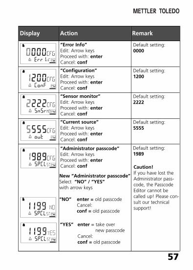
57
Caution!If you have lost theAdministrator pass-code, the PasscodeEditor cannot becalled up! Please con-sult our technicalsupport!
Display Action Remark
“Error Info”Edit: Arrow keysProceed with: enterCancel: conf
Default setting:0000
“Configuration”Edit: Arrow keysProceed with: enterCancel: conf
Default setting:1200
“Sensor monitor”Edit: Arrow keysProceed with: enterCancel: conf
Default setting:2222
“Current source”Edit: Arrow keysProceed with: enterCancel: conf
Default setting:5555
“Administrator passcode”Edit: Arrow keysProceed with: enterCancel: conf
Default setting:1989
New “Administrator passcode”Select “NO” / “YES” with arrow keys
“NO” enter = old passcodeCancel:conf = old passcode
“YES” enter = take overnew passcode
Cancel:conf = old passcode
70098_E_CI7100_2XH.QXD 27.07.2005 9:27 Uhr Seite 57
58 Transmitter Cond Ind 7100e/2(X)
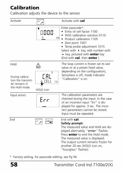
CalibrationCalibration adjusts the device to the sensor.
Activate with cal
Enter passcode*: • Entry of cell factor 1100• With calibration solution 0110• Product calibration 1105• Zero point 1001• Temp probe adjustment 1015Select with key, edit number with key, proceed with enter key (End with cal, then enter.)
The loop current is frozen (at its lastvalue or at a preset fixed value,depending on the configuration),Sensoface is off, mode indicator“Calibration” is on.
Activate
Hold
Input errors The calibration parameters arechecked during the input. In the caseof an incorrect input ”Err” is dis-played for approx. 3 sec. The incor-rect parameters cannot be stored.Input must be repeated.
End End with cal.Safety prompt:The measured value and Hold are dis-played alternately, “enter” flashes. Press enter to end the Hold mode. The measured value is displayed. The output current remains frozen foranother 20 sec (HOLD icon on,“hourglass” flashes).
HOLD icon
During calibra-tion the transmit-ter remains inthe Hold mode.
* Factory setting, for passcode editing, see Pg 56
70098_E_CI7100_2XH.QXD 27.07.2005 9:27 Uhr Seite 58
59
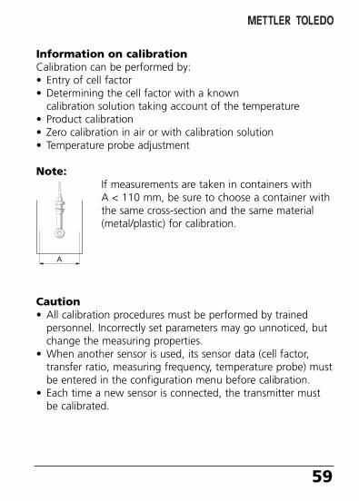
Information on calibrationCalibration can be performed by:• Entry of cell factor• Determining the cell factor with a known
calibration solution taking account of the temperature• Product calibration• Zero calibration in air or with calibration solution• Temperature probe adjustment
Note:If measurements are taken in containers with A < 110 mm, be sure to choose a container withthe same cross-section and the same material(metal/plastic) for calibration.
Caution• All calibration procedures must be performed by trained
personnel. Incorrectly set parameters may go unnoticed, butchange the measuring properties.
• When another sensor is used, its sensor data (cell factor,transfer ratio, measuring frequency, temperature probe) mustbe entered in the configuration menu before calibration.
• Each time a new sensor is connected, the transmitter mustbe calibrated.
70098_E_CI7100_2XH.QXD 27.07.2005 9:27 Uhr Seite 59
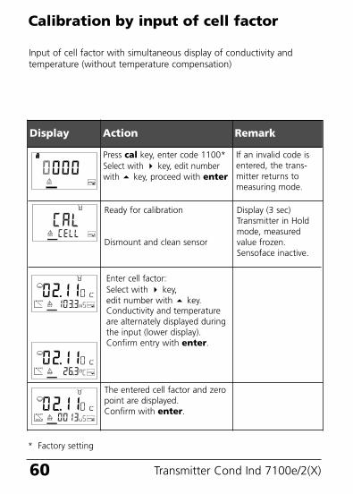
60 Transmitter Cond Ind 7100e/2(X)
Display Action Remark
Enter cell factor:Select with key, edit number with key.Conductivity and temperatureare alternately displayed duringthe input (lower display).Confirm entry with enter.
Calibration by input of cell factor
Press cal key, enter code 1100*Select with key, edit numberwith key, proceed with enter
Ready for calibration
Dismount and clean sensor
If an invalid code isentered, the trans-mitter returns tomeasuring mode.
The entered cell factor and zeropoint are displayed.Confirm with enter.
Display (3 sec)Transmitter in Holdmode, measuredvalue frozen.Sensoface inactive.
Input of cell factor with simultaneous display of conductivity andtemperature (without temperature compensation)
* Factory setting
70098_E_CI7100_2XH.QXD 27.07.2005 9:27 Uhr Seite 60
61
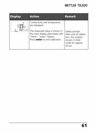
Display Action Remark
Conductivity and temperatureare displayed.
The measured value is shown inthe main display alternately with“Hold”; “enter” flashes.Press enter to end calibration.
Safety promptAfter end of calibra-tion, the outputsremain in Holdmode for approx.20 sec.
70098_E_CI7100_2XH.QXD 27.07.2005 9:27 Uhr Seite 61
62 Transmitter Cond Ind 7100e/2(X)
Display Action Remark
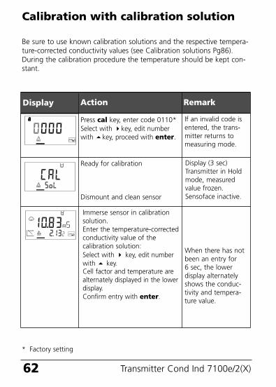
Calibration with calibration solution
Press cal key, enter code 0110*Select with key, edit numberwith key, proceed with enter.
Ready for calibration
Dismount and clean sensor
If an invalid code isentered, the trans-mitter returns tomeasuring mode.
Display (3 sec)Transmitter in Holdmode, measuredvalue frozen.Sensoface inactive.
Be sure to use known calibration solutions and the respective tempera-ture-corrected conductivity values (see Calibration solutions Pg86).During the calibration procedure the temperature should be kept con-stant.
Immerse sensor in calibrationsolution.Enter the temperature-correctedconductivity value of thecalibration solution: Select with key, edit numberwith key.Cell factor and temperature arealternately displayed in the lowerdisplay.Confirm entry with enter.
When there has notbeen an entry for6 sec, the lowerdisplay alternatelyshows the conduc-tivity and tempera-ture value.
* Factory setting
70098_E_CI7100_2XH.QXD 27.07.2005 9:27 Uhr Seite 62
63
Display Action Remark
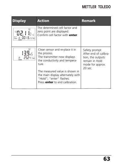
The determined cell factor andzero point are displayed.Confirm cell factor with enter.
Clean sensor and re-place it inthe process.The transmitter now displaysthe conductivity and tempera-ture.
The measured value is shown inthe main display alternately with“Hold”; “enter” flashes. Press enter to end calibration.
Safety promptAfter end of calibra-tion, the outputsremain in Holdmode for approx.20 sec.
70098_E_CI7100_2XH.QXD 27.07.2005 9:28 Uhr Seite 63
64 Transmitter Cond Ind 7100e/2(X)
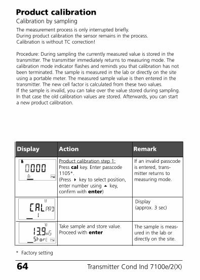
The measurement process is only interrupted briefly. During product calibration the sensor remains in the process.Calibration is without TC correction!
Procedure: During sampling the currently measured value is stored in thetransmitter. The transmitter immediately returns to measuring mode. Thecalibration mode indicator flashes and reminds you that calibration has notbeen terminated. The sample is measured in the lab or directly on the siteusing a portable meter. The measured sample value is then entered in thetransmitter. The new cell factor is calculated from these two values.If the sample is invalid, you can take over the value stored during sampling.In that case the old calibration values are stored. Afterwards, you can starta new product calibration.
Product calibrationCalibration by sampling
Display Action Remark
Product calibration step 1:Press cal key. Enter passcode1105*.(Press key to select position,enter number using key, confirm with enter)
Take sample and store value.Proceed with enter
If an invalid passcodeis entered, trans-mitter returns tomeasuring mode.
The sample is meas-ured in the lab ordirectly on the site.
Display (approx. 3 sec)
* Factory setting
70098_E_CI7100_2XH.QXD 27.07.2005 9:28 Uhr Seite 64
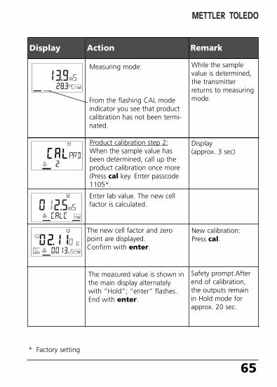
Product calibration step 2:When the sample value hasbeen determined, call up theproduct calibration once more(Press cal key. Enter passcode1105*.
65
Display Action Remark
Measuring mode:
From the flashing CAL modeindicator you see that productcalibration has not been termi-nated.
Display (approx. 3 sec)
Enter lab value. The new cellfactor is calculated.
While the samplevalue is determined,the transmitterreturns to measuringmode.
The new cell factor and zeropoint are displayed. Confirm with enter.
The measured value is shown inthe main display alternatelywith “Hold”; “enter” flashes.End with enter.
Safety prompt.Afterend of calibration,the outputs remainin Hold mode forapprox. 20 sec.
New calibration:Press cal.
* Factory setting
70098_E_CI7100_2XH.QXD 27.07.2005 9:28 Uhr Seite 65
66 Transmitter Cond Ind 7100e/2(X)
Display Action Remark
When there has notbeen an entry for6 sec, the lowerdisplay alternatelyshows the conductiv-ity and temperaturevalue.
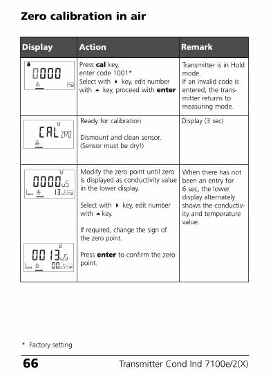
Zero calibration in air
Press cal key,enter code 1001*Select with key, edit numberwith key, proceed with enter
Modify the zero point until zerois displayed as conductivity valuein the lower display.
Select with key, edit numberwith key.
If required, change the sign ofthe zero point.
Press enter to confirm the zeropoint.
Transmitter is in Holdmode.If an invalid code isentered, the trans-mitter returns tomeasuring mode.
Ready for calibration
Dismount and clean sensor.(Sensor must be dry!)
Display (3 sec)
* Factory setting
70098_E_CI7100_2XH.QXD 27.07.2005 9:28 Uhr Seite 66
67
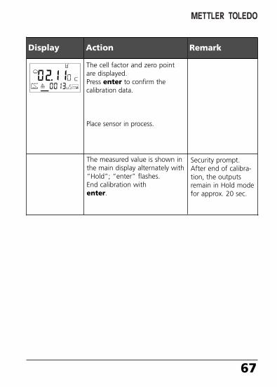
Display Action Remark
The cell factor and zero pointare displayed.Press enter to confirm thecalibration data.
Place sensor in process.
The measured value is shown inthe main display alternately with“Hold”; “enter” flashes.End calibration with enter.
Security prompt.After end of calibra-tion, the outputsremain in Hold modefor approx. 20 sec.
70098_E_CI7100_2XH.QXD 27.07.2005 9:28 Uhr Seite 67
68 Transmitter Cond Ind 7100e/2(X)
Display Action Remark
When there has notbeen an entry for6 sec, the lowerdisplay alternatelyshows the conductiv-ity and temperaturevalue.
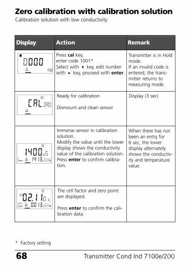
Zero calibration with calibration solutionCalibration solution with low conductivity
Press cal key,enter code 1001*Select with key, edit numberwith key, proceed with enter.
Immerse sensor in calibrationsolution.Modify the value until the lowerdisplay shows the conductivityvalue of the calibration solution.Press enter to confirm calibra-tion.
Transmitter is in Holdmode.If an invalid code isentered, the trans-mitter returns tomeasuring mode.
Ready for calibration
Dismount and clean sensor
Display (3 sec)
The cell factor and zero pointare displayed.
Press enter to confirm the cali-bration data.
* Factory setting
70098_E_CI7100_2XH.QXD 27.07.2005 9:28 Uhr Seite 68
69
Display Action Remark
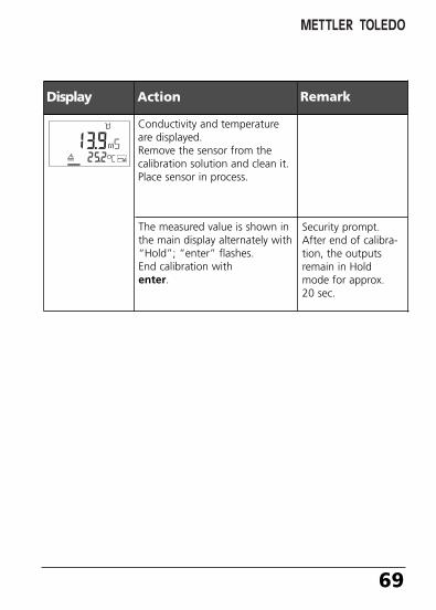
Conductivity and temperatureare displayed.Remove the sensor from thecalibration solution and clean it.Place sensor in process.
The measured value is shown inthe main display alternately with“Hold”; “enter” flashes.End calibration withenter.
Security prompt.After end of calibra-tion, the outputsremain in Holdmode for approx.20 sec.
70098_E_CI7100_2XH.QXD 27.07.2005 9:28 Uhr Seite 69
70 Transmitter Cond Ind 7100e/2(X)
Display Remark
Measurement
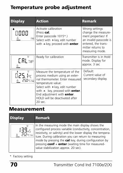
In the measuring mode the main display shows theconfigured process variable (conductivity, concentration,resistivity, or salinity) and the lower display the tempera-ture. During calibration you can return to measuringmode by pressing the cal key, during configuration bypressing conf + enter (waiting time for measured-value stabilization approx. 20 sec).
Display Action Remark
Measure the temperature of theprocess medium using an exter-nal thermometer. Enter measuredtemperature value:Select with key, edit numberwith key, proceed with enter.End adjustment with enter.HOLD will be deactivated after20 sec.
Temperature probe adjustment
Activate calibration(Press cal,Enter passcode 1015*.)Select with key, edit numberwith key, proceed with enter.
Ready for calibration
Wrong settingschange the measure-ment properties! Ifan invalid passcode isentered, the trans-mitter returns tomeasuring mode.
Default:Current value ofsecondary display.
Transmitter is in Holdmode. Display forapprox. 3 sec
* Factory setting
70098_E_CI7100_2XH.QXD 27.07.2005 9:28 Uhr Seite 70
71
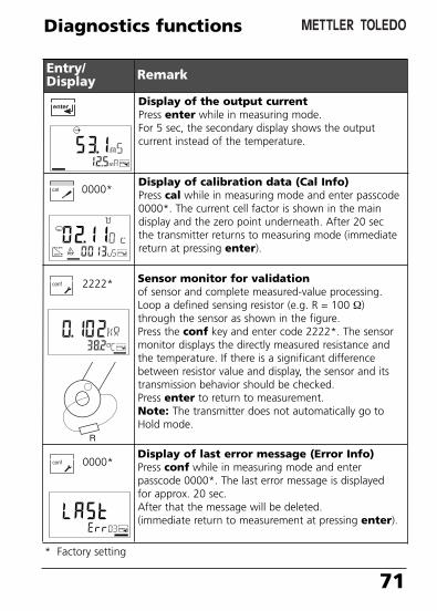
Display of the output currentPress enter while in measuring mode.For 5 sec, the secondary display shows the outputcurrent instead of the temperature.
Diagnostics functions
Entry/Display Remark
Display of calibration data (Cal Info)Press cal while in measuring mode and enter passcode0000*. The current cell factor is shown in the maindisplay and the zero point underneath. After 20 secthe transmitter returns to measuring mode (immediatereturn at pressing enter).
Display of last error message (Error Info)Press conf while in measuring mode and enter passcode 0000*. The last error message is displayedfor approx. 20 sec. After that the message will be deleted.(immediate return to measurement at pressing enter).
0000*
2222*
0000*
Sensor monitor for validationof sensor and complete measured-value processing.Loop a defined sensing resistor (e.g. R = 100 Ω)through the sensor as shown in the figure.Press the conf key and enter code 2222*. The sensormonitor displays the directly measured resistance andthe temperature. If there is a significant differencebetween resistor value and display, the sensor and itstransmission behavior should be checked. Press enter to return to measurement.Note: The transmitter does not automatically go toHold mode.
* Factory setting
70098_E_CI7100_2XH.QXD 27.07.2005 9:28 Uhr Seite 71
72 Transmitter Cond Ind 7100e/2(X)
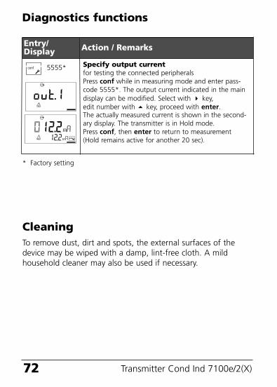
Specify output currentfor testing the connected peripheralsPress conf while in measuring mode and enter pass-code 5555*. The output current indicated in the maindisplay can be modified. Select with key, edit number with key, proceed with enter.The actually measured current is shown in the second-ary display. The transmitter is in Hold mode.Press conf, then enter to return to measurement (Hold remains active for another 20 sec).
Diagnostics functions
Entry/Display Action / Remarks
5555*
CleaningTo remove dust, dirt and spots, the external surfaces of thedevice may be wiped with a damp, lint-free cloth. A mildhousehold cleaner may also be used if necessary.
* Factory setting
70098_E_CI7100_2XH.QXD 27.07.2005 9:28 Uhr Seite 72
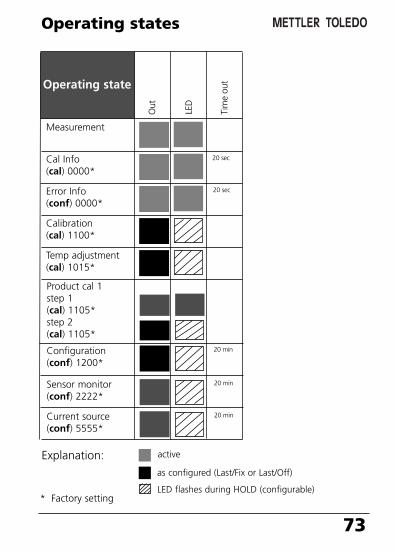
Operating state
73
Measurement
Operating states
Cal Info(cal) 0000*
20 sec
Error Info(conf) 0000*
20 sec
Calibration(cal) 1100*
Temp adjustment(cal) 1015*
LED
Tim
e ou
t
Out
Explanation: active
as configured (Last/Fix or Last/Off)
LED flashes during HOLD (configurable)* Factory setting
Product cal 1step 1(cal) 1105*step 2(cal) 1105*
Configuration(conf) 1200*
20 min
Sensor monitor(conf) 2222*
20 min
Current source(conf) 5555*
20 min
70098_E_CI7100_2XH.QXD 27.07.2005 9:28 Uhr Seite 73
Measuredvalueflashes
74 Transmitter Cond Ind 7100e/2(X)
Red
LED
Out
1 (
22 m
A)
Error messages (Error Codes)
Sensor• Measurement range violation• SAL > 45 ‰• Sensor connection or cable defective• Wrong cell factor
Error Display ProblemPossible causes
ERR 01 Measuredvalueflashes
xx
Unsuitable sensorConductance range > 3000 mS
ERR 02 xx
System errorConfiguration or calibration datadefective. Completely reconfigureand recalibrate the device.Memory error in device program
ERR 98 “Conf”flashes
xx
Factory settingsEEPROM or RAM defectiveThis error message only occurs inthe case of a total defect. Thetransmitter must be repaired andrecalibrated at the factory.
ERR 99 “FAIL”flashes
xx
Temperature probeOpen or short circuitTemperature range exceeded
ERR 03 xx
70098_E_CI7100_2XH.QXD 27.07.2005 9:28 Uhr Seite 74
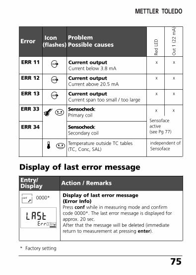
75
Sensocheck:Primary coil
Sensocheck:Secondary coil
Red
LED
Out
1 (2
2 m
A)
Current outputCurrent below 3.8 mA
Error Icon(flashes)
ProblemPossible causes
ERR 11 xx
Current outputCurrent above 20.5 mA
ERR 12 xx
Current outputCurrent span too small / too large
ERR 13 xx
ERR 33 xx
Temperature outside TC tables (TC, Conc, SAL)
independent ofSensoface
Sensofaceactive(see Pg 77)
Display of last error message(Error Info)Press conf while in measuring mode and confirm code 0000*. The last error message is displayed forapprox. 20 sec. After that the message will be deleted (immediatereturn to measurement at pressing enter).
Display of last error message
Entry/Display Action / Remarks
ERR 34
0000*
* Factory setting
70098_E_CI7100_2XH.QXD 27.07.2005 9:28 Uhr Seite 75
76 Transmitter Cond Ind 7100e/2(X)
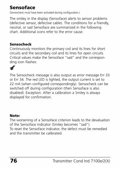
SensocheckContinuously monitors the primary coil and its lines for shortcircuits and the secondary coil and its lines for open circuits.Critical values make the Sensoface “sad” and the correspon-ding icon flashes:
The Sensocheck message is also output as error message Err 33or Err 34. The red LED is lighted, the output current is set to 22 mA (when configured correspondingly). Sensocheck can beswitched off during configuration (then Sensoface is alsodisabled). Exception: After a calibration a Smiley is alwaysdisplayed for confirmation.
Sensoface(Sensocheck must have been activated during configuration.)
The smiley in the display (Sensoface) alerts to sensor problems(defective sensor, defective cable). The conditions for a friendly,neutral, or sad Sensoface are summarized in the followingchart. Additional icons refer to the error cause.
Note:The worsening of a Sensoface criterion leads to the devaluationof the Sensoface indicator (Smiley becomes “sad”). To reset the Sensoface indicator, the defect must be remediedand the transmitter be calibrated.
70098_E_CI7100_2XH.QXD 27.07.2005 9:28 Uhr Seite 76
77
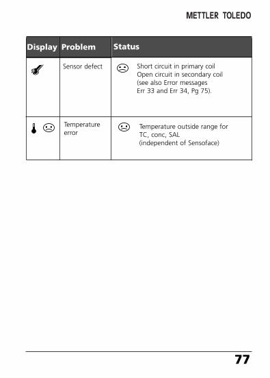
StatusDisplay Problem
Sensor defect Short circuit in primary coilOpen circuit in secondary coil (see also Error messagesErr 33 and Err 34, Pg 75).
Temperature outside range for TC, conc, SAL(independent of Sensoface)
Temperatureerror
70098_E_CI7100_2XH.QXD 27.07.2005 9:28 Uhr Seite 77
78 Transmitter Cond Ind 7100e/2(X)
70098_E_CI7100_2XH.QXD 27.07.2005 9:28 Uhr Seite 78
79
Appendix
Product line and accessories
Devices Order no.
Transmitter Cond Ind 7100e/2H 52 121 257Transmitter Cond Ind 7100e/2XH 52 121 258
Mounting accessoriesPipe-mount kit 52 120 741Panel-mount kit 52 120 740Protective hood 52 120 739
SensorsMettler-Toledo GmbH, Process Analytics offers a wide range ofelectrodeless sensors for the following fields of applications:- Chemical process industry- Pharmaceutical industry- Food and beverage industry- Pulp and paper industry- Water/waste-water treatmentFor more information concerning our sensors and housings program,please refer to our website:
http://www.mtpro.com
70098_E_CI7100_2XH.QXD 27.07.2005 9:28 Uhr Seite 79
80 Transmitter Cond Ind 7100e/2(X)H
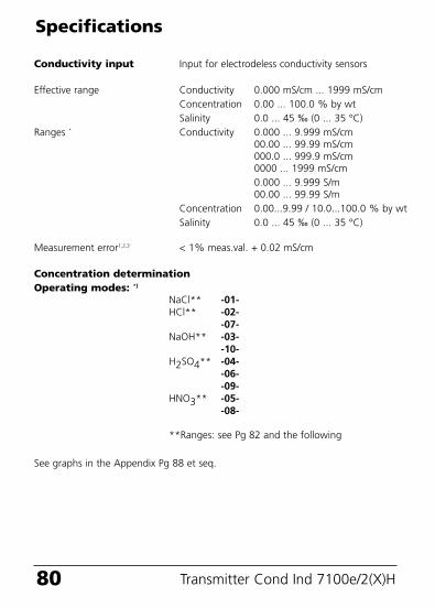
Conductivity input Input for electrodeless conductivity sensors
Effective range Conductivity 0.000 mS/cm ... 1999 mS/cmConcentration 0.00 ... 100.0 % by wtSalinity 0.0 ... 45 ‰ (0 ... 35 °C)
Ranges * Conductivity 0.000 ... 9.999 mS/cm00.00 ... 99.99 mS/cm000.0 ... 999.9 mS/cm0000 ... 1999 mS/cm0.000 ... 9.999 S/m00.00 ... 99.99 S/m
Concentration 0.00...9.99 / 10.0...100.0 % by wtSalinity 0.0 ... 45 ‰ (0 ... 35 °C)
Measurement error1,2,3 < 1% meas.val. + 0.02 mS/cm
Concentration determinationOperating modes: *)
NaCl** -01-HCl** -02-
-07-NaOH** -03-
-10-H2SO4** -04-
-06--09-
HNO3** -05--08-
**Ranges: see Pg 82 and the following
See graphs in the Appendix Pg 88 et seq.
Specifications
70098_E_CI7100_2XH.QXD 27.07.2005 9:28 Uhr Seite 80
81
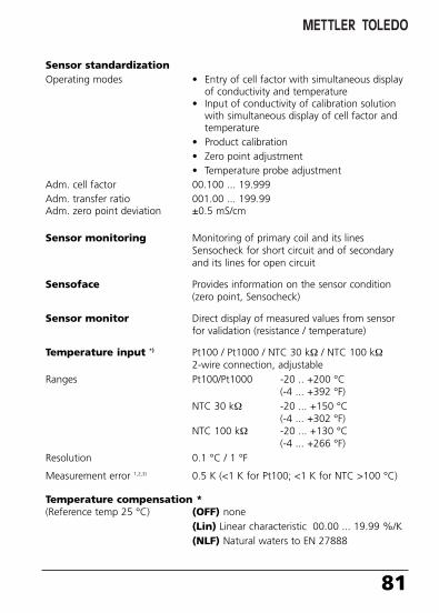
Sensor standardizationOperating modes • Entry of cell factor with simultaneous display
of conductivity and temperature • Input of conductivity of calibration solution
with simultaneous display of cell factor and temperature
• Product calibration• Zero point adjustment• Temperature probe adjustment
Adm. cell factor 00.100 ... 19.999Adm. transfer ratio 001.00 ... 199.99Adm. zero point deviation ±0.5 mS/cm
Sensor monitoring Monitoring of primary coil and its lines Sensocheck for short circuit and of secondary and its lines for open circuit
Sensoface Provides information on the sensor condition(zero point, Sensocheck)
Sensor monitor Direct display of measured values from sensor for validation (resistance / temperature)
Temperature input *) Pt100 / Pt1000 / NTC 30 kΩ / NTC 100 kΩ2-wire connection, adjustable
Ranges Pt100/Pt1000 -20 .. +200 °C(-4 ... +392 °F)
NTC 30 kΩ -20 ... +150 °C(-4 ... +302 °F)
NTC 100 kΩ -20 ... +130 °C(-4 ... +266 °F)
Resolution 0.1 °C / 1 °F
Measurement error 1,2,3) 0.5 K (<1 K for Pt100; <1 K for NTC >100 °C)
Temperature compensation *(Reference temp 25 °C) (OFF) none
(Lin) Linear characteristic 00.00 ... 19.99 %/K(NLF) Natural waters to EN 27888
70098_E_CI7100_2XH.QXD 27.07.2005 9:28 Uhr Seite 81
Transmitter Cond Ind 7100e/2(X)
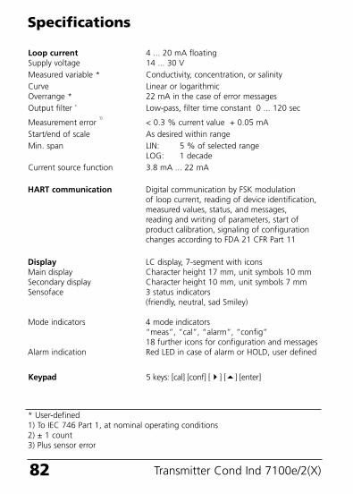
Loop current 4 ... 20 mA floating Supply voltage 14 ... 30 VMeasured variable * Conductivity, concentration, or salinityCurve Linear or logarithmicOverrange * 22 mA in the case of error messagesOutput filter * Low-pass, filter time constant 0 ... 120 sec
Measurement error 1)
< 0.3 % current value + 0.05 mAStart/end of scale As desired within rangeMin. span LIN: 5 % of selected range
LOG: 1 decadeCurrent source function 3.8 mA ... 22 mA
82
Specifications
HART communication Digital communication by FSK modulation of loop current, reading of device identification,measured values, status, and messages, reading and writing of parameters, start of product calibration, signaling of configuration changes according to FDA 21 CFR Part 11
Display LC display, 7-segment with iconsMain display Character height 17 mm, unit symbols 10 mmSecondary display Character height 10 mm, unit symbols 7 mmSensoface 3 status indicators
(friendly, neutral, sad Smiley)
Mode indicators 4 mode indicators “meas”, “cal”, “alarm”, “config”18 further icons for configuration and messages
Alarm indication Red LED in case of alarm or HOLD, user defined
Keypad 5 keys: [cal] [conf] [] [] [enter]
* User-defined1) To IEC 746 Part 1, at nominal operating conditions2) ± 1 count3) Plus sensor error
70098_E_CI7100_2XH.QXD 27.07.2005 9:28 Uhr Seite 82
83
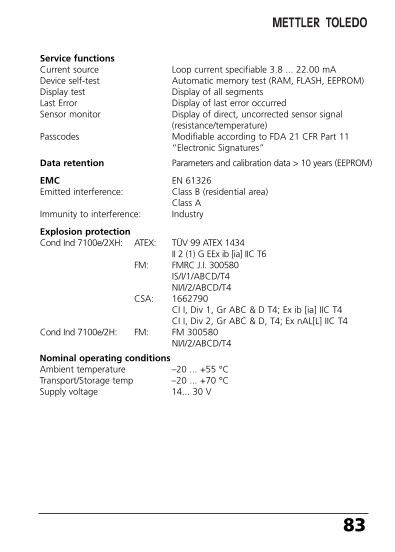
Service functionsCurrent source Loop current specifiable 3.8 ... 22.00 mADevice self-test Automatic memory test (RAM, FLASH, EEPROM)Display test Display of all segmentsLast Error Display of last error occurredSensor monitor Display of direct, uncorrected sensor signal
(resistance/temperature)Passcodes Modifiable according to FDA 21 CFR Part 11
“Electronic Signatures”
Data retention Parameters and calibration data > 10 years (EEPROM)
EMC EN 61326Emitted interference: Class B (residential area)
Class AImmunity to interference: Industry
Explosion protectionCond Ind 7100e/2XH: ATEX: TÜV 99 ATEX 1434
II 2 (1) G EEx ib [ia] IIC T6FM: FMRC J.I. 300580
IS/I/1/ABCD/T4NI/I/2/ABCD/T4
CSA: 1662790CI I, Div 1, Gr ABC & D T4; Ex ib [ia] IIC T4CI I, Div 2, Gr ABC & D, T4; Ex nAL[L] IIC T4
Cond Ind 7100e/2H: FM: FM 300580NI/I/2/ABCD/T4
Nominal operating conditionsAmbient temperature –20 ... +55 °CTransport/Storage temp –20 ... +70 °CSupply voltage 14... 30 V
70098_E_CI7100_2XH.QXD 27.07.2005 9:28 Uhr Seite 83
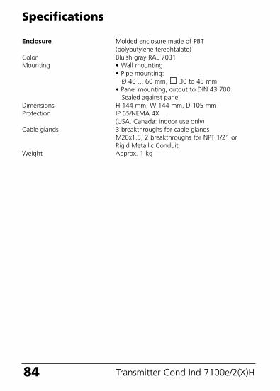
84 Transmitter Cond Ind 7100e/2(X)H
Enclosure Molded enclosure made of PBT(polybutylene terephtalate)
Color Bluish gray RAL 7031Mounting • Wall mounting
• Pipe mounting: Ø 40 ... 60 mm, 30 to 45 mm
• Panel mounting, cutout to DIN 43 700Sealed against panel
Dimensions H 144 mm, W 144 mm, D 105 mmProtection IP 65/NEMA 4X
(USA, Canada: indoor use only)Cable glands 3 breakthroughs for cable glands
M20x1.5, 2 breakthroughs for NPT 1/2” or Rigid Metallic Conduit
Weight Approx. 1 kg
Specifications
70098_E_CI7100_2XH.QXD 27.07.2005 9:28 Uhr Seite 84

85
70098_E_CI7100_2XH.QXD 27.07.2005 9:28 Uhr Seite 85
Transmitter Cond Ind 7100e/2(X)86
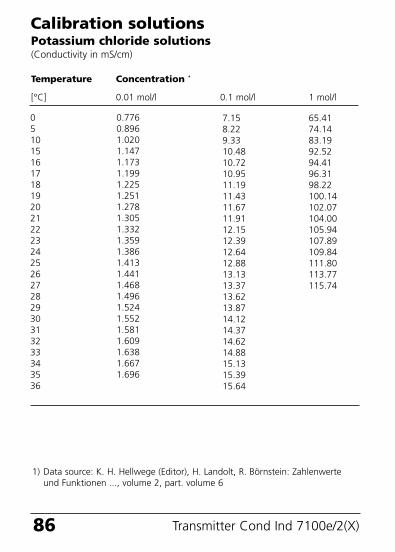
Calibration solutionsPotassium chloride solutions(Conductivity in mS/cm)
Temperature Concentration *
[°C] 0.01 mol/l 0.1 mol/l 1 mol/l
051015161718192021222324252627282930313233343536
0.7760.8961.0201.1471.1731.1991.2251.2511.2781.3051.3321.3591.3861.4131.4411.4681.4961.5241.5521.5811.6091.6381.6671.696
7.158.229.3310.4810.7210.9511.1911.4311.6711.9112.1512.3912.6412.8813.1313.3713.6213.8714.1214.3714.6214.8815.1315.3915.64
65.4174.1483.1992.5294.4196.3198.22100.14102.07104.00105.94107.89109.84111.80113.77115.74
1) Data source: K. H. Hellwege (Editor), H. Landolt, R. Börnstein: Zahlenwerteund Funktionen ..., volume 2, part. volume 6
70098_E_CI7100_2XH.QXD 27.07.2005 9:28 Uhr Seite 86

87
Sodium chloride solutions(Conductivity in mS/cm)
0123456789
101112131415161718192021222324252627282930313233343536
134.5138.6142.7146.9151.2155.5159.9164.3168.8173.4177.9182.6187.2191.9196.7201.5206.3211.2216.1221.0226.0231.0236.1241.1246.2251.3256.5261.6266.9272.1277.4282.7288.0293.3298.7304.1309.5
5.7865.9656.1456.3276.5106.6956.8817.0687.2577.4477.6387.8318.0258.2218.4188.6178.8169.0189.2219.4259.6319.838
10.04710.25810.46910.68310.89811.11411.33211.55211.77311.99512.22012.44512.67312.90213.132
0.6310.6510.6710.6920.7120.7330.7540.7750.7960.8180.8390.8610.8830.9050.9270.9500.9720.9951.0181.0411.0641.0871.1111.1351.1591.1831.2071.2321.2561.2811.3061.3311.3571.3821.4081.4341.460
Temperature Concentration
[°C] 0.01 mol/l * 0.1 mol/l * saturated **
1) Data source: Test solutions calculated according to DIN IEC 746-32) Data source: K. H. Hellwege (Editor), H. Landolt, R. Börnstein: Zahlenwerte
und Funktionen ..., volume 2, part. volume 6
70098_E_CI7100_2XH.QXD 27.07.2005 9:28 Uhr Seite 87
88 Transmitter Cond Ind 7100e/2(X)
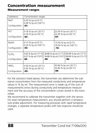
Concentration measurementMeasurement ranges
For the solutions listed above, the transmitter can determine the sub-stance concentration from the measured conductivity and temperaturevalues in % by wt. The measurement error is made up of the sum ofmeasurements errors during conductivity and temperature measure-ment and the accuracy of the concentration curves stored in the trans-mitter. We recommend to calibrate the transmitter together with the sensor.For exact temperature measurement, you should perform a tempera-ture probe adjustment. For measuring processes with rapid temperaturechanges, a separate temperature probe with fast response should beused.
0-18 % by wt (-20 °C)0-18 % by wt (50 °C)-02-
Substance Concentration ranges
NaCl
Configuration
0-26 % by wt (0 °C)0-28 % by wt (100 °C)-01-
HCl
Configuration
22-39 % by wt (-20 °C)22-39 % by wt (50 °C)-07-
NaOH
Configuration
0-13 % by wt (0 °C)0-24 % by wt (100 °C)-03-
H2SO4
Configuration
0-26 % by wt (-17 °C)0-37 % by wt (110°C)-04-
28-88 % by wt (-17 °C)39-88 % by wt (115°C)-09-
94-99 % by wt (-17 °C)89-99 % by wt (115 °C)-06-
HNO3
Configuration
35-96 % by wt (-20 °C)35-96 % by wt (50 °C)-08-
0-30 % by wt (-20 °C)0-30 % by wt (50 °C)-05-
15-50 % by wt (0 °C)35-50 % by wt (100 °C)-10-
70098_E_CI7100_2XH.QXD 27.07.2005 9:28 Uhr Seite 88
89
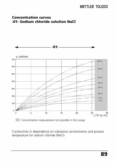
Conductivity in dependence on substance concentration and processtemperature for sodium chloride (NaCl)
Concentration curves-01- Sodium chloride solution NaCl
-01-
Concentration measurement not possible in this range.
c [% by wt]
70098_E_CI7100_2XH.QXD 27.07.2005 9:28 Uhr Seite 89
90 Transmitter Cond Ind 7100e/2(X)
Conductivity in dependence on substance concentration and processtemperature for hydrochloric acid (HCl)Source: Haase/Sauermann/Dücker; Z. phys. Chem. New Edition, Vol. 47(1965)
-02- Hydrochloric acid solution HCl-07-
-02- -07-
c [% by wt]
Concentration measurement not possible in this range.
70098_E_CI7100_2XH.QXD 27.07.2005 9:28 Uhr Seite 90
91
Conductivity in dependence on substance concentration andprocess temperature for sodium hydroxide solution (NaOH)
-03- Sodium hydroxide solution NaOH-10-
-03- -10-
c [% by wt]Concentration measurement not possible in this range.
70098_E_CI7100_2XH.QXD 27.07.2005 9:28 Uhr Seite 91
92 Transmitter Cond Ind 7100e/2(X)
Conductivity in dependence on substance concentration and processtemperature for sulfuric acid (H2SO4), Source: Darling; Journal of Chemical and Engineering Data; Vol. 9 No. 3, July 1964
-04- Sulphuric acid H2SO4
-06--09-
-04- -09- -06-
c [% by wt]
Concentration measurement not possible in this range.
70098_E_CI7100_2XH.QXD 27.07.2005 9:28 Uhr Seite 92
93
Conductivity in dependence on substance concentration and processtemperature for nitric acid (HN03)Source: Haase/Sauermann/Dücker; Z. phys. Chem. New Edition, Vol. 46(1965)
-05- Nitric acid HNO3
-08-
-05- -08-
c [% by wt]Concentration measurement not possible in this range.
70098_E_CI7100_2XH.QXD 27.07.2005 9:28 Uhr Seite 93
94 Transmitter Cond Ind 7100e/2(X)H
FM Control Drawing
70098_E_CI7100_2XH.QXD 27.07.2005 9:28 Uhr Seite 94
95
70098_E_CI7100_2XH.QXD 27.07.2005 9:28 Uhr Seite 95
96 Transmitter Cond Ind 7100e/2(X)H
Explosion protection
70098_E_CI7100_2XH.QXD 27.07.2005 9:28 Uhr Seite 96

97
Warnings and notes to ensure safe operation
Warning: Do not disconnect equipment unless power hasbeen switched off.
Warning: Clean only with antistatic moistened cloth.Warning: Substitution of components may impair suitability
for hazardous locations.
• The equipment shall be installed and protected from mechanicalimpact and ultraviolet (UV) sources.
• Clean only with a moistened antistatic cloth as potential electrostatic hazard may exist. Service equipment only with conductive clothing, footwear and personal grounding devicesto prevent electrostatic accumulation.
• Internal grounding provisions shall be provided for field wiring. Bonding between conduit shall be provided during installation, and all exposed non-current carrying metallic parts shall be bonded and grounded.
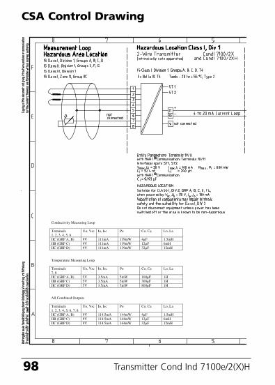
• Installation in a Class I, Division 2 or Class I, Zone 2 hazardouslocation shall be in accordance with the Canadian ElectricalCode (CEC Part 1) Section 18 Division 2 wiring methods.
OBSERVE THE SPECIFICATIONS OF THE CONTROLDRAWING!
70098_E_CI7100_2XH.QXD 27.07.2005 9:28 Uhr Seite 97
98 Transmitter Cond Ind 7100e/2(X)H
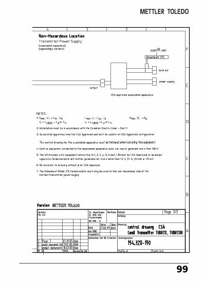
CSA Control Drawing
Conductivity Measuring Loop
Terminals1, 2, 3, 4, 5, 6
Uo, Vsc Io, Isc Po Co, Ca Lo, La
IIC (GRP A, B) 9V 111mA 139mW 4µF 1.5mHIIB (GRP C) 9V 111mA 139mW 12µF 6mHIIC (GRP D) 9V 111mA 139mW 32µF 12mH
Temperature Measuring Loop
Terminals7, 8
Uo, Vsc Io, Isc Po Co, Ca Lo, La
IIC (GRP A, B) 5V 3.5mA 5mW 100µF 1HIIB (GRP C) 5V 3.5mA 5mW 300µF 1HIIC (GRP D) 5V 3.5mA 5mW 800µF 1H
All Combined Outputs
Terminals1, 2, 3, 4, 5, 6, 7, 8
Uo, Vsc Io, Isc Po Co, Ca Lo, La
IIC (GRP A, B) 9V 114.5mA 144mW 4µF 1.5mHIIB (GRP C) 9V 114.5mA 144mW 12µF 6mHIIC (GRP D) 9V 114.5mA 144mW 32µF 12mH
70098_E_CI7100_2XH.QXD 27.07.2005 9:28 Uhr Seite 98
99
70098_E_CI7100_2XH.QXD 27.07.2005 9:28 Uhr Seite 99
100 Transmitter Cond Ind 7100e/2(X)
70098_E_CI7100_2XH.QXD 27.07.2005 9:28 Uhr Seite 100
22 mA signal for error message . . . . . . . . . . . . . . . . . . . . 51
AAccessories . . . . . . . . . . . . . . . . . . . . . . . . . . . . . . . . . . . . 79Alarm . . . . . . . . . . . . . . . . . . . . . . . . . . . . . . . . . . . . . . . . 31Alarm settings . . . . . . . . . . . . . . . . . . . . . . . . . . . . . . . . . . 54Attenuation . . . . . . . . . . . . . . . . . . . . . . . . . . . . . . . . . . . 49Audit Trail . . . . . . . . . . . . . . . . . . . . . . . . . . . . . . . . . . . . . . 9
CCalibration . . . . . . . . . . . . . . . . . . . . . . . . . . . . . . . . . . . . 58
by input of cell factor . . . . . . . . . . . . . . . . . . . . . . . . . .60by sampling . . . . . . . . . . . . . . . . . . . . . . . . . . . . . . . . .64Display of calibration data . . . . . . . . . . . . . . . . . . . . . .71with calibration solution . . . . . . . . . . . . . . . . . . . . . . . .62Zero calibration in air . . . . . . . . . . . . . . . . . . . . . . . . . .66Zero calibration with calibration solution . . . . . . . . . . .68
Calibration solutions . . . . . . . . . . . . . . . . . . . . . . . . . . . . . 86Cleaning . . . . . . . . . . . . . . . . . . . . . . . . . . . . . . . . . . . . . . 72Concentration measurement . . . . . . . . . . . . . . . . . . . . . . . 43
Concentration curves . . . . . . . . . . . . . . . . . . . . . . . . . .89Ranges . . . . . . . . . . . . . . . . . . . . . . . . . . . . . . . . . . . . .88
Configuration . . . . . . . . . . . . . . . . . . . . . . . . . . . . . . . . . . 34Alarm settings . . . . . . . . . . . . . . . . . . . . . . . . . . . . . . .54Current start/end . . . . . . . . . . . . . . . . . . . . . . . . . . . . .44Factory setting . . . . . . . . . . . . . . . . . . . . . . . . . . . . . . .36Individual settings . . . . . . . . . . . . . . . . . . . . . . . . . . . . .37LIN characteristic . . . . . . . . . . . . . . . . . . . . . . . . . . . . .44LOG characteristic . . . . . . . . . . . . . . . . . . . . . . . . . . . .46Measured variable . . . . . . . . . . . . . . . . . . . . . . . . . . . .40Process solution . . . . . . . . . . . . . . . . . . . . . . . . . . . . . .42Sensor type . . . . . . . . . . . . . . . . . . . . . . . . . . . . . . . . .38Time constant of output filter . . . . . . . . . . . . . . . . . . .48
101
Index
70098_E_CI7100_2XH.QXD 27.07.2005 9:28 Uhr Seite 101
Configuration steps . . . . . . . . . . . . . . . . . . . . . . . . . . . . . 36Connection . . . . . . . . . . . . . . . . . . . . . . . . . . . . . . . . . . . . 20Connection to supply units . . . . . . . . . . . . . . . . . . . . . . 6, 20Contents . . . . . . . . . . . . . . . . . . . . . . . . . . . . . . . . . . . . . . . 3Control Drawing . . . . . . . . . . . . . . . . . . . . . . . . . . . . . 94, 98CSA Control Drawing . . . . . . . . . . . . . . . . . . . . . . . . . . . . 98Current output . . . . . . . . . . . . . . . . . . . . . . . . . . . . . . . . . 31
Configuration . . . . . . . . . . . . . . . . . . . . . . . . . . . . .38, 50Display of output current . . . . . . . . . . . . . . . . . . . . . . .71
Current start/end . . . . . . . . . . . . . . . . . . . . . . . . . . . . . . . 45
DDiagnostics functions . . . . . . . . . . . . . . . . . . . . . . . . . 71, 72Display . . . . . . . . . . . . . . . . . . . . . . . . . . . . . . . . . . . . . . . 27Disposal . . . . . . . . . . . . . . . . . . . . . . . . . . . . . . . . . . . . . . . 2Division 2 wiring . . . . . . . . . . . . . . . . . . . . . . . . . . . . . . . . 20
EEC Declaration of Conformity . . . . . . . . . . . . . . . . . . . . . . . 8EC-Type-Examination Certificate . . . . . . . . . . . . . . . . . 10, 13Electronic Signature . . . . . . . . . . . . . . . . . . . . . . . . . . . . . . 9EMC . . . . . . . . . . . . . . . . . . . . . . . . . . . . . . . . . . . . . . . . . 83Error Info . . . . . . . . . . . . . . . . . . . . . . . . . . . . . . . . . . . . . 75Error messages . . . . . . . . . . . . . . . . . . . . . . . . . . . . . . . . . 74
Display of last error message . . . . . . . . . . . . . . . . . . . .71Explosion protection . . . . . . . . . . . . . . . . . . . . . . . . . . . . . 83
Certificate . . . . . . . . . . . . . . . . . . . . . . . . . . . . . . . . . .96Safety information . . . . . . . . . . . . . . . . . . . . . . . . . . . . .6
FFDA 21 CFR Part 11 . . . . . . . . . . . . . . . . . . . . . . . . . . . . . . 9FM Control Drawing . . . . . . . . . . . . . . . . . . . . . . . . . . . . . 94
102 Transmitter Cond Ind 7100e/2(X)
Index
70098_E_CI7100_2XH.QXD 27.07.2005 9:28 Uhr Seite 102
HHART communication . . . . . . . . . . . . . . . . . . . . . . . . . . . . 31Hold mode . . . . . . . . . . . . . . . . . . . . . . . . . . . . . . . . . . . . 30
LED in HOLD mode . . . . . . . . . . . . . . . . . . . . . . . . . . .55Output signal for HOLD . . . . . . . . . . . . . . . . . . . . . . . .51
IInstallation . . . . . . . . . . . . . . . . . . . . . . . . . . . . . . . . . . . . 20
Safety precautions . . . . . . . . . . . . . . . . . . . . . . . . . . . . .6Intended use . . . . . . . . . . . . . . . . . . . . . . . . . . . . . . . . . . . . 7
KKeypad . . . . . . . . . . . . . . . . . . . . . . . . . . . . . . . . . . . . . . . 28
LLoop current . . . . . . . . . . . . . . . . . . . . . . . . . . . . . . . . . . . 31
MMeasurement . . . . . . . . . . . . . . . . . . . . . . . . . . . . . . . . . . 70Measurement range over 3 decades . . . . . . . . . . . . . . . . . 47Mounting plan . . . . . . . . . . . . . . . . . . . . . . . . . . . . . . . . . 17
OOperating states . . . . . . . . . . . . . . . . . . . . . . . . . . . . . . . . 73Output current . . . . . . . . . . . . . . . . . . . . . . . . . . . . . . . . . 31
Output current during Error and HOLD . . . . . . . . . . . . .50Specify output current . . . . . . . . . . . . . . . . . . . . . . . . .72
Overview . . . . . . . . . . . . . . . . . . . . . . . . . . . . . . . . . . 15, 21
103
70098_E_CI7100_2XH.QXD 27.07.2005 9:28 Uhr Seite 103
PPackage contents . . . . . . . . . . . . . . . . . . . . . . . . . . . . . . . 16Panel-mount kit . . . . . . . . . . . . . . . . . . . . . . . . . . . . . . . . 19Passcode editor . . . . . . . . . . . . . . . . . . . . . . . . . . . . . . . . . 56Passcodes (factory setting) . . . . . . . . . . . . . . . . . . . . . . . . 33Pipe-mount kit . . . . . . . . . . . . . . . . . . . . . . . . . . . . . . . . . 18Product calibration . . . . . . . . . . . . . . . . . . . . . . . . . . . . . . 64Product line and accessories . . . . . . . . . . . . . . . . . . . . . . . 79Protective hood . . . . . . . . . . . . . . . . . . . . . . . . . . . . . . . . . 18
RReturn of products . . . . . . . . . . . . . . . . . . . . . . . . . . . . . . . 2
SSafety functions . . . . . . . . . . . . . . . . . . . . . . . . . . . . . . . . 29
Automatic device self-test . . . . . . . . . . . . . . . . . . . . . .29GainCheck device self-test . . . . . . . . . . . . . . . . . . . . . .29Sensocheck, Sensoface sensor monitoring . . . . . . . . . .29
Safety information . . . . . . . . . . . . . . . . . . . . . . . . . . . . . 5, 6Self test . . . . . . . . . . . . . . . . . . . . . . . . . . . . . . . . . . . . . . 29Sensocheck . . . . . . . . . . . . . . . . . . . . . . . . . . . . . . . . . 55, 76Sensoface . . . . . . . . . . . . . . . . . . . . . . . . . . . . . . . . . . . . . 76Sensor monitor . . . . . . . . . . . . . . . . . . . . . . . . . . . . . . . . . 71Sensors . . . . . . . . . . . . . . . . . . . . . . . . . . . . . . . . . . . . . . . 79
Wiring . . . . . . . . . . . . . . . . . . . . . . . . . . . . . . . . . . . . .24Specifications . . . . . . . . . . . . . . . . . . . . . . . . . . . . . . . . . . 80
TTemperature compensation . . . . . . . . . . . . . . . . . . . . . . . . 52Temperature probe adjustment . . . . . . . . . . . . . . . . . . . . . 70Time constant of output filter . . . . . . . . . . . . . . . . . . . . . . 49Trademarks . . . . . . . . . . . . . . . . . . . . . . . . . . . . . . . . . . . . . 7
104 Transmitter Cond Ind 7100e/2(X)
Index
70098_E_CI7100_2XH.QXD 27.07.2005 9:28 Uhr Seite 104
UUser interface . . . . . . . . . . . . . . . . . . . . . . . . . . . . . . . . . . 26
WWarranty . . . . . . . . . . . . . . . . . . . . . . . . . . . . . . . . . . . . . . . 2Wiring examples . . . . . . . . . . . . . . . . . . . . . . . . . . . . . . . . 24
105
70098_E_CI7100_2XH.QXD 27.07.2005 9:28 Uhr Seite 105

70098_E_CI7100_2XH.QXD 27.07.2005 9:28 Uhr Seite 106

70098_E_CI7100_2XH.QXD 27.07.2005 9:28 Uhr Seite 107
TA-194.301-MTE02 011005 Software version: 1.1
Mettler-Toledo GmbH, Process AnalyticsIndustrie Nord, CH-8902 Urdorf, SwitzerlandPhone + 41 44 736 22 11, Fax +41 44 736 26 36
Subject to technical changes.© Mettler-Toledo GmbH, Process Analytics10/05 Printed in Switzerland. 52 120 967
70098_E_CI7100_2XH.QXD 27.07.2005 9:28 Uhr Seite 108


![HTP100EX-A - orga.nl · • EN 60079-0, EN 60079-7, EN 60079-11 and EN 60079-18 • IECEx DEK 11.0072; Ex e mb [ib] IIC T6 Gb • IEC 60079-0, IEC 60079-7, IEC 60079-11 and IEC 60079-18](https://img.pdfslide.net/doc/110x75/5c61b5de09d3f25b7d8b926a/htp100ex-a-organl-en-60079-0-en-60079-7-en-60079-11-and-en-60079-18.jpg)