Embed Size (px)
Citation preview
INSTRUCTION MANUAL MODEL 7322
PRESSURIZED CONSISTOMETER
Revision L – November 2016 P/N 7322-0005
S/N __________
2001 N. Indianwood Ave.,
Broken Arrow, Oklahoma 74012 Tel: 918-250-7200 Telefax: 918-459-0165
E-mail: [email protected] Website: www.chandlereng.com

Copyright 2016, by Chandler Engineering Company, LLC P.O. Box 470710 Tulsa, Oklahoma 74147 All rights reserved. Reproduction or use of contents in any manner is prohibited without express permission from Chandler Engineering Company, LLC. While every precaution has been taken in the preparation of this manual, the publisher assumes no responsibility for errors or omissions. Neither is any liability assumed for damages resulting from the use of the information contained herein. This publication contains the following trademarks and/or registered trademarks for: AMETEK and CHANDLER ENGINEERING. These trademarks or registered trademarks and stylized logos are all owned by AMETEK, Inc. All other company, product and service names and logos are trademarks or service marks of their respective owners.
TABLE OF CONTENTS T-1
Table of Contents Page
General Information ....................................................................... P-1
Application of the Consistometer ..................................................................................................... P-1 Description of Apparatus ................................................................................................................. P-1 Safety Requirements ........................................................................................................................ P-4 Where to Find Help ......................................................................................................................... P-4
Section 1 – Installation ................................................................... 1-1
Unpacking the Instrument................................................................................................................ 1-1 Utility Requirements ........................................................................................................................ 1-1 Tools and Equipment Required........................................................................................................ 1-1 Setting up the Instrument ................................................................................................................ 1-1
Connecting Air and Water .......................................................................................................... 1-1 Connecting Power to the Consistometer ..................................................................................... 1-2
Section 2 – Operating Instructions ................................................. 2-1
Preparing the Instrument for a Test ................................................................................................. 2-1 Configuring the Consistency Display .......................................................................................... 2-1 Programming the Temperature and Pressure Controllers ............................................................ 2-1 Hesitation Squeeze ..................................................................................................................... 2-2 API Slurry Cup Preparation ....................................................................................................... 2-2
Running a Test ................................................................................................................................ 2-3 After the Test is Complete ............................................................................................................... 2-4
Draining the Test Cell of Oil....................................................................................................... 2-5
Section 3 - Maintenance ................................................................. 3-1
Chillers ............................................................................................................................................ 3-1 After Every Test .............................................................................................................................. 3-1
Pressure Cylinder ....................................................................................................................... 3-1 Potentiometer Mechanism .......................................................................................................... 3-1 Slurry Cup ................................................................................................................................. 3-1 Thermocouple (Slurry Cup) ....................................................................................................... 3-2 Thermocouple (Oil).................................................................................................................... 3-2
Monthly .......................................................................................................................................... 3-2 Potentiometer Mechanism .......................................................................................................... 3-2 Resistor Replacement ................................................................................................................. 3-2 Calibration Spring Replacement ................................................................................................. 3-2 Potentiometer Calibration........................................................................................................... 3-3 Magnetic Drive .......................................................................................................................... 3-3 Thermocouple and Temperature Control System ........................................................................ 3-4
Three Months .................................................................................................................................. 3-4 Oil and Filter .............................................................................................................................. 3-4 Drive Motor ............................................................................................................................... 3-4
T-2 TABLE OF CONTENTS
Six Months ...................................................................................................................................... 3-4 Timer ......................................................................................................................................... 3-4 Air Operated Valve .................................................................................................................... 3-4
Annually .......................................................................................................................................... 3-5 Pump ......................................................................................................................................... 3-5 Reservoir ................................................................................................................................... 3-5 Heater ........................................................................................................................................ 3-5 Thermocouple and Temperature Controller ................................................................................ 3-5
Section 4 – Troubleshooting Guide ................................................ 4-1
Section 5 - Replacement Parts ........................................................ 5-1
Section 6 - Drawings and Schematics ............................................. 6-1
PREFACE P-1
General Information Application of the Consistometer
Cements have numerous applications in the drilling, completion, work-over, and abandonment of wells. For each application, the cement is designed with special properties and is given additives that provide predictable slurry density, volume, viscosity, compressive strength, and thickening time. Thickening time, or the time a cement slurry remains able to be pumped into the well, is one of the most critical properties in designing a slurry. A short thickening time is desired, while maintaining the special properties of the cement's design. The thickening time of a slurry can be measured in a laboratory by testing a sample of the slurry in a Pressurized Consistometer. The elapsed time between an initial application of pressure and temperature on the slurry sample and the development of 100 Bearden units of consistency (Bc) is the thickening time for the sample at a particular specification test schedule [Table 8.2, API Spec 10(1)].
Description of Apparatus The Model 7322 is designed so that closure, heating, and pressurization can be achieved quickly. The pressurized consistometer incorporates a rotating, cylindrical slurry cup equipped with a stationary paddle assembly enclosed in a pressure chamber designed for a working pressure of 154 MPa (22,000 psi) at a maximum temperature of 205°C (400°F). An air-operated hydraulic pump generates pressure to the cylinder assembly. The hydraulic system incorporates a reservoir, piping, valves and filters. Heat is supplied to the chamber by a 2200-watt, internal, tubular heater. Thermocouples are provided for determining the temperatures of the oil bath and cement slurry. The programmable temperature controller automatically controls the rate of temperature rise (i.e. temperature gradient). When the slurry reaches the desired temperature, the controller will hold the temperature at that level. Hydraulic pressure is generated with an air operated high-pressure pump. Pressure settings are maintained through the control of a pressure relief valve and air pressure available to the pump. The slurry container is rotated at a constant speed of 150 +/- 15 rpm by a magnetic drive. Drive torque is transmitted from a set of outside drive magnets, through a non-magnetic housing, to permanent magnets attached to the rotating shaft within the cylinder. Permanent, rare earth magnets are used to ensure high torque and a long magnetic-field life. The viscosity (i.e. consistency) of the cement slurry is recorded on a chart as BC (Bearden Units) obtained from a potentiometer installed within the pressure cylinder. The potentiometer contains a standardized torsion spring, which resists the rotating force of the paddle. Rotational force is proportional to consistency of the cement slurry.
REFERENCES (1) American Petroleum Institute; API Specification for Materials and Testing for Well Cements, Latest Edition; Dallas, TX.

P-2 PREFACE
In the Model 7322, pressure is controlled using a dynamic, programmable pressurization system. The temperature, pressure and the viscosity of the slurry are recorded on a strip chart in the electronics module. An interface is also included for PC based data acquisition. The Chandler Model 5270 Instrument Control System is specifically designed for this interface. Using the Model 5270 software, hesitation squeeze treatments can also be simulated using the programmable motor and pressure control capabilities.
PREFACE P-3
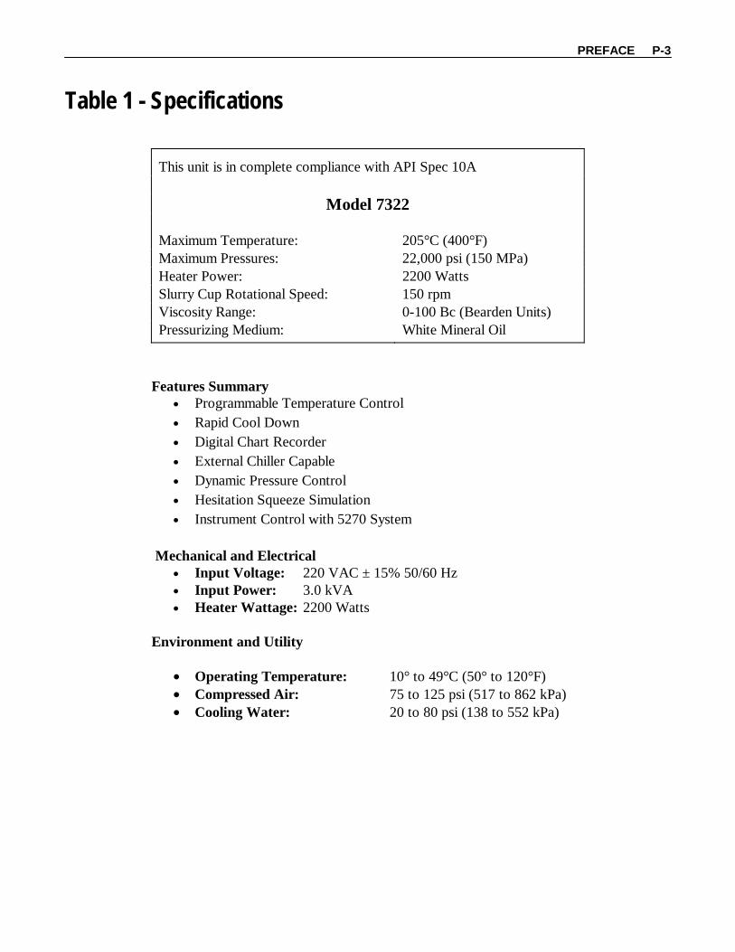
Table 1 - Specifications
This unit is in complete compliance with API Spec 10A
Model 7322 Maximum Temperature: 205°C (400°F) Maximum Pressures: 22,000 psi (150 MPa) Heater Power: 2200 Watts Slurry Cup Rotational Speed: 150 rpm Viscosity Range: 0-100 Bc (Bearden Units) Pressurizing Medium: White Mineral Oil
Features Summary
• Programmable Temperature Control • Rapid Cool Down • Digital Chart Recorder • External Chiller Capable • Dynamic Pressure Control • Hesitation Squeeze Simulation • Instrument Control with 5270 System
Mechanical and Electrical
• Input Voltage: 220 VAC ± 15% 50/60 Hz • Input Power: 3.0 kVA • Heater Wattage: 2200 Watts
Environment and Utility
• Operating Temperature: 10° to 49°C (50° to 120°F) • Compressed Air: 75 to 125 psi (517 to 862 kPa) • Cooling Water: 20 to 80 psi (138 to 552 kPa)
P-4 PREFACE
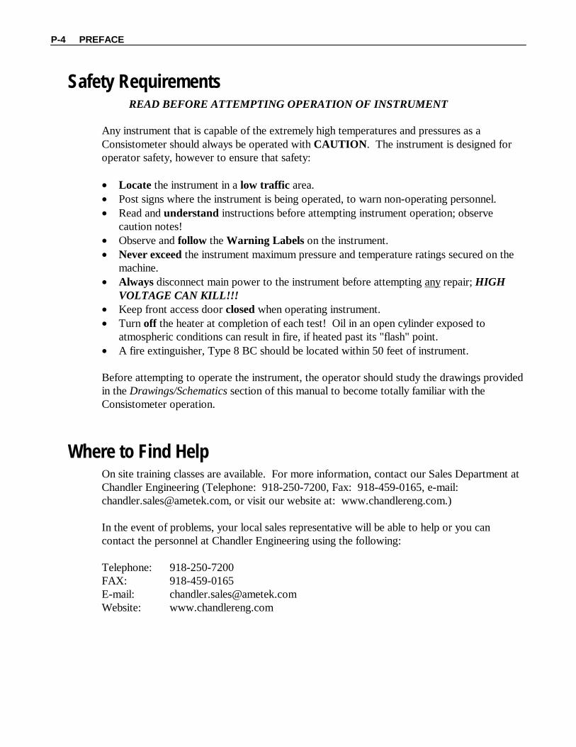
Safety Requirements READ BEFORE ATTEMPTING OPERATION OF INSTRUMENT
Any instrument that is capable of the extremely high temperatures and pressures as a Consistometer should always be operated with CAUTION. The instrument is designed for operator safety, however to ensure that safety:
• Locate the instrument in a low traffic area. • Post signs where the instrument is being operated, to warn non-operating personnel. • Read and understand instructions before attempting instrument operation; observe
caution notes! • Observe and follow the Warning Labels on the instrument. • Never exceed the instrument maximum pressure and temperature ratings secured on the
machine. • Always disconnect main power to the instrument before attempting any repair; HIGH
VOLTAGE CAN KILL!!! • Keep front access door closed when operating instrument. • Turn off the heater at completion of each test! Oil in an open cylinder exposed to
atmospheric conditions can result in fire, if heated past its "flash" point. • A fire extinguisher, Type 8 BC should be located within 50 feet of instrument.
Before attempting to operate the instrument, the operator should study the drawings provided in the Drawings/Schematics section of this manual to become totally familiar with the Consistometer operation.
Where to Find Help On site training classes are available. For more information, contact our Sales Department at Chandler Engineering (Telephone: 918-250-7200, Fax: 918-459-0165, e-mail: [email protected], or visit our website at: www.chandlereng.com.) In the event of problems, your local sales representative will be able to help or you can contact the personnel at Chandler Engineering using the following: Telephone: 918-250-7200 FAX: 918-459-0165 E-mail: [email protected] Website: www.chandlereng.com
SECTION 1 – INSTALLATION 1-1
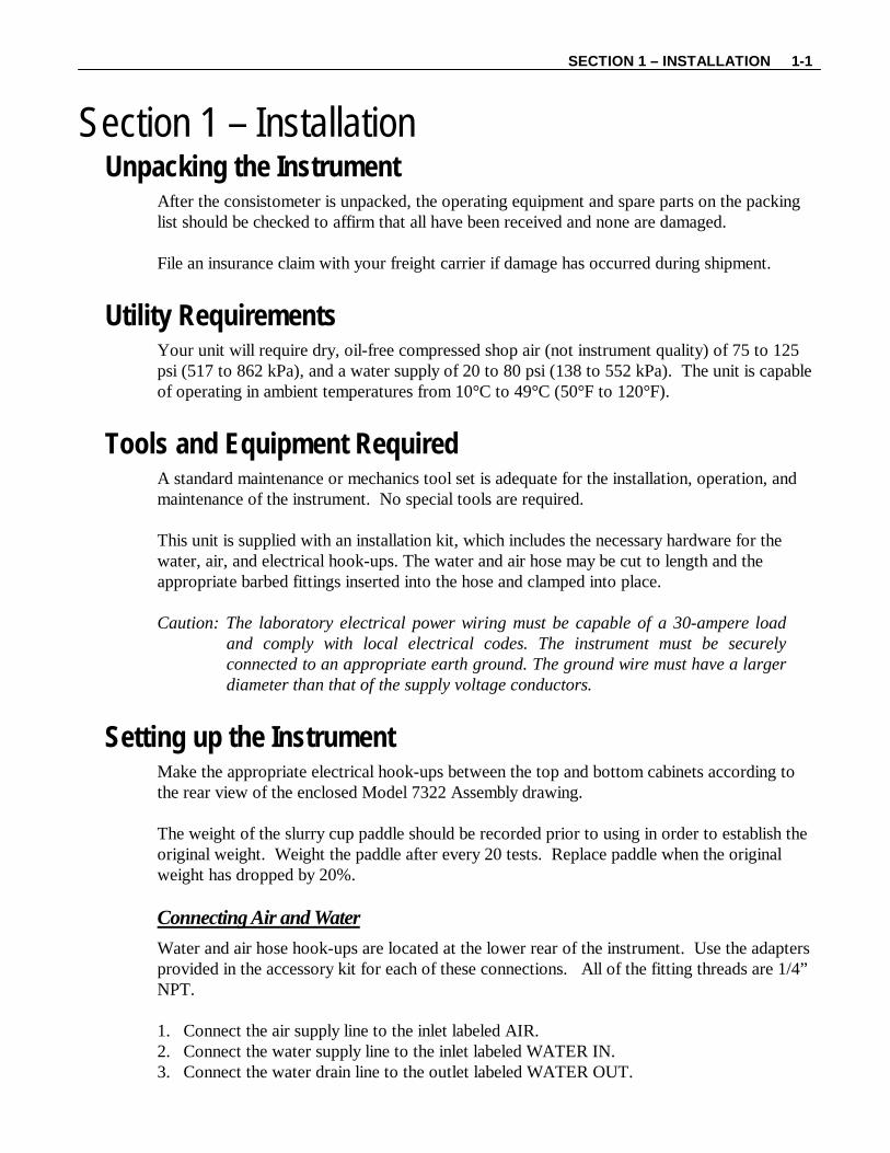
Section 1 – Installation Unpacking the Instrument
After the consistometer is unpacked, the operating equipment and spare parts on the packing list should be checked to affirm that all have been received and none are damaged. File an insurance claim with your freight carrier if damage has occurred during shipment.
Utility Requirements Your unit will require dry, oil-free compressed shop air (not instrument quality) of 75 to 125 psi (517 to 862 kPa), and a water supply of 20 to 80 psi (138 to 552 kPa). The unit is capable of operating in ambient temperatures from 10°C to 49°C (50°F to 120°F).
Tools and Equipment Required A standard maintenance or mechanics tool set is adequate for the installation, operation, and maintenance of the instrument. No special tools are required. This unit is supplied with an installation kit, which includes the necessary hardware for the water, air, and electrical hook-ups. The water and air hose may be cut to length and the appropriate barbed fittings inserted into the hose and clamped into place.
Caution: The laboratory electrical power wiring must be capable of a 30-ampere load
and comply with local electrical codes. The instrument must be securely connected to an appropriate earth ground. The ground wire must have a larger diameter than that of the supply voltage conductors.
Setting up the Instrument Make the appropriate electrical hook-ups between the top and bottom cabinets according to the rear view of the enclosed Model 7322 Assembly drawing. The weight of the slurry cup paddle should be recorded prior to using in order to establish the original weight. Weight the paddle after every 20 tests. Replace paddle when the original weight has dropped by 20%. Connecting Air and Water
Water and air hose hook-ups are located at the lower rear of the instrument. Use the adapters provided in the accessory kit for each of these connections. All of the fitting threads are 1/4” NPT. 1. Connect the air supply line to the inlet labeled AIR. 2. Connect the water supply line to the inlet labeled WATER IN. 3. Connect the water drain line to the outlet labeled WATER OUT.

1-2 SECTION 1 – INSTALLATION
Connecting Power to the Consistometer
1. Connect the supplied twist-on power connector to the receptacle at the rear of the unit. 2. Connect the power plug to an appropriately rated power source and receptacle. For user
safety a power plug and mating receptacle are required. Note: This receptacle MUST be properly grounded.
SECTION 2 – OPERATING INSTRUCTIONS 2-1
Section 2 – Operating Instructions The chart recorder is configured at the factory and will be ready for use at power-up. A manual has been enclosed for your reference. The Bearden unit indicator is pre-configured at the factory to alarm at 100 Bc. The alarms control four items. First, an audible alarm is triggered; second, the heater current is cut off; third, the motor is shut off; and fourth, the timer is stopped.
Preparing the Instrument for a Test Prior to running a test, the following steps must be performed. Configuring the Consistency Display
1. Turn on the instrument.
2. Press or (Up or Down) to change the alarm limit. A manual has been enclosed for your reference. Programming the Temperature and Pressure Controllers
The programming for the temperature and pressure controllers is identical. Following is a brief procedure for programming the controllers. For complete instructions, see the Model 8050/8051 Temperature Controller and Model 8060/8061 Pressure Controller manuals.
1. Press and hold the Advance key for approximately five seconds. The profile prompt (ProF) will appear in the lower display and the profile number (e.g. P1) appears in the upper display.
2. Multiple profiles (P1 to P4) can be stored in the device. The shortcut keys (EZ1 and EZ2) are factory configured to start and stop profile P1. The 5270 DACS software also utilizes
P1 when a profile is downloaded to the controller for an automated test. Press the Up
or Down keys to select P1.
3. Press the Advance Key to move to the first step.
4. Press the Up or Down keys to move through and select the step type.
5. Press the Advance Key to move through the selected step settings.
6. Press the Up or Down keys to change the step settings. 7. Press the Infinity Key at any time to return to the step number prompt. 8. Press the Infinity Key again to return to the profile number prompt. 9. From any point press and hold the Infinity Key for two seconds to return to the Home
Page. 10. To manually start or stop a profile, press either the EZ1 or EZ2 key.
2-2 SECTION 2 – OPERATING INSTRUCTIONS
Hesitation Squeeze
The motor can be programmed to run a hesitation squeeze schedule using the 5270 DACS software. To allow the motor to run continuously during a test, place the motor switch in the ON position. To allow the 5270 DACS software to control the motor, place the motor switch AUTO position. Refer to the 5270 online help files for detailed information on setting up hesitation squeeze schedules. API Slurry Cup Preparation
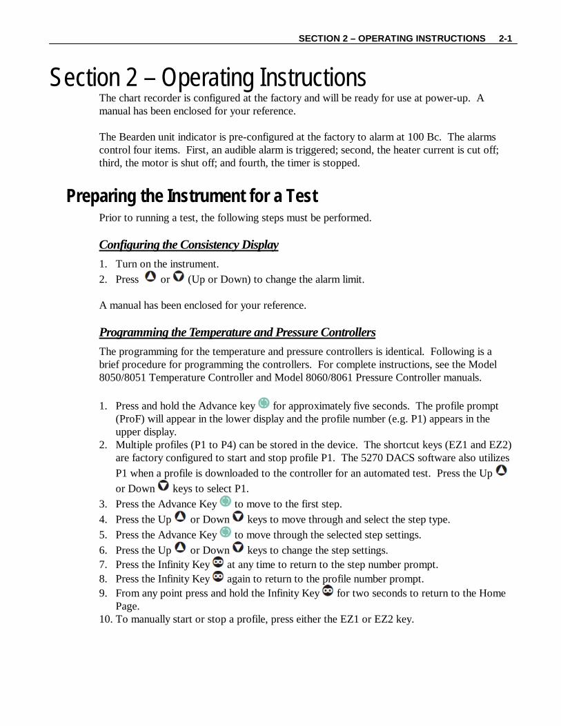
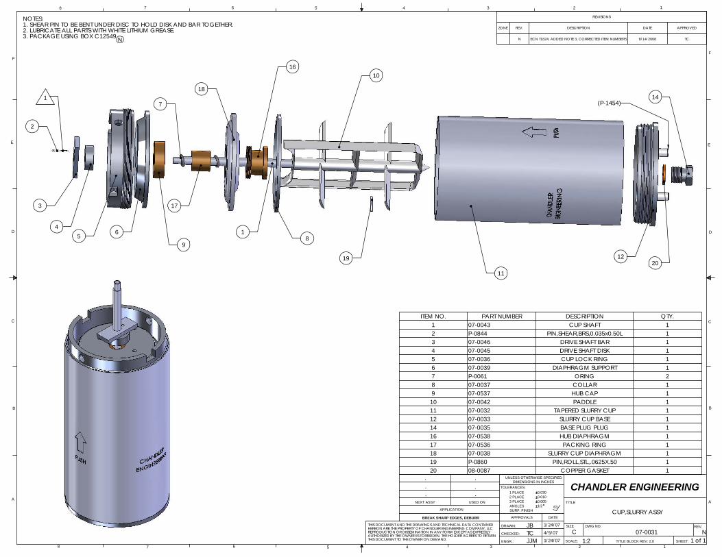
For an accurate thickening time test to be performed, it is important for the slurry cup to be properly maintained and prepared. The following procedure should serve as a guideline for slurry cup preparations. While assembling the slurry cup, refer to drawing 07-0031 in the Drawings section of this manual. 1. Thoroughly clean all parts and verify that all parts are in good condition. 2. Lightly grease all interior surfaces of the slurry cup with white lithium grease or the
equivalent. 3. Install the diaphragm support ring, the diaphragm, and the diaphragm backup plate onto
the paddle assembly. The diaphragm should be oriented so that the larger brass piece is at the top.
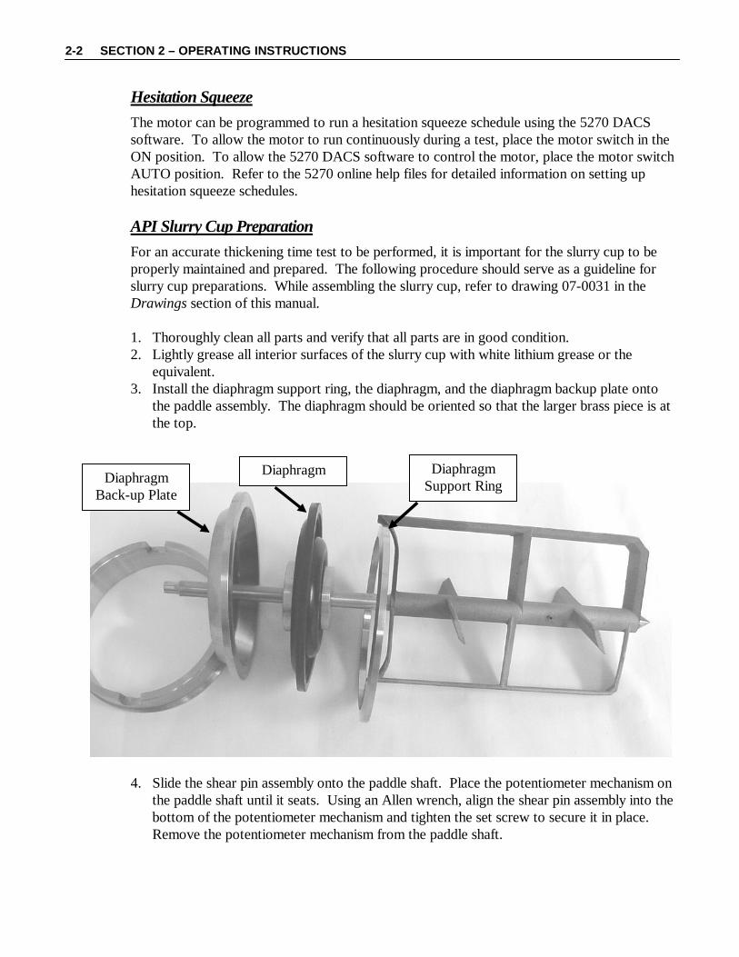
4. Slide the shear pin assembly onto the paddle shaft. Place the potentiometer mechanism on
the paddle shaft until it seats. Using an Allen wrench, align the shear pin assembly into the bottom of the potentiometer mechanism and tighten the set screw to secure it in place. Remove the potentiometer mechanism from the paddle shaft.
Diaphragm Back-up Plate
Diaphragm Support Ring
Diaphragm
SECTION 2 – OPERATING INSTRUCTIONS 2-3
5. Install the complete paddle assembly into the slurry cup. 6. Screw the diaphragm lock-down ring into the top of the slurry cup while checking to
make sure the paddle turns freely. 7. Invert the slurry cup into the slurry cup support. 8. Prepare the cement slurry in accordance with API Spec 10. Caution: According to API specs: The cement has to be under test (under pressure)
within 5 minutes of mixing. 9. Fill the cup with prepared cement slurry to the bottom of the threads. 10. Remove the plug (pivot) from the center of the bottom cap. 11. Replace the bottom cap without the plug. Slowly screw the cap into place and add
cement through the hole if required. 12. Grease the plug and replace. 13. Rinse the exterior surfaces of the slurry cup.
Running a Test 1. Remove the test cell plug, if it is not already removed from a previous test. 2. Attach the long bail through the holes on the top of the prepared slurry cup and insert it
into the test cell, rotating it until the bottom pins engage the cup drive table. Remove the bail.
3. After the slurry cup is loaded into the cell, the potentiometer mechanism (pot. mech.) is pushed onto the slurry cup paddle shaft and the test cell contact pins. Attach the short bail to the top of the potentiometer and lower the pot mech into the test cell. When properly engaged, the top of the paddle shaft will be flush with the top of the torque measurement potentiometer bearing. Remove the bail.
4. Check to be certain that the slurry cup and pot mech are properly engaged. Turn the Motor switch to ON. No rubbing noise should be heard.
Shear Pin Assembly
2-4 SECTION 2 – OPERATING INSTRUCTIONS
5. Screw the test cell plug into the cylinder by hand. The last turn of the plug seats the O-Ring seal and will offer slight resistance.
Note: Do not over-tighten the test cell plug. Hand-tightening the plug is sufficient
for a complete seal. 6. Slide the thermocouple through the test cell plug into the slurry cup paddle shaft. Start
the threads of the sealing gland into the test cell plug, but do not tighten the thermocouple at this time. Verify that the thermocouple is plugged in at the rear of the instrument.
7. Next, fill the test cell with oil. To accomplish this, close the Pressure Release Valve, and turn the CYLINDER Control Valve to the FILL position. When oil escapes from the top thermocouple high-pressure fitting, tighten the sealing gland with a 5/8” wrench.
8. Turn the Pump Switch to the AUTO position to apply the initial pressure to the test cell. When the pressure reaches the desired level, turn the Pump Switch to the OFF position. Adjust the pressure as required throughout the test by turning the Pump Switch to FILL to increase pressure or by slowly cracking open the Pressure Release Valve to relieve pressure. Use care to open the Pressure Release Valve slowly when attempting to bleed pressure.
9. To begin the test, the Temperature Controller and Pressure Controller programs must be started as follows.
10. Press the Advance Key to display the Control Mode (AUTO, OFF or MAN). Press the
Up or Down keys to select AUTO. Press the Infinity Key to return to the main screen. Press the EZ1 button to start the program. The “1” light should begin flashing indicating the control output to the heater and or pump.
11. Turn the Heater and Pump Switch to the ON position, and start the timer. (The heater and pump will not start until the program start up is initiated through the controller.)
Note: Turn the coolant control switch to ON if an external chiller is used. After the final temperature is reached for the schedule being run, the controller will continue on a programmed soak until the schedule is completed. Note: Once a program has been entered into the controller it may be reused by
pressing the EZ1 button to run the program again.
After the Test is Complete A buzzer will sound, signaling the slurry has reached the required consistency. The controllers must now be shut down as follows:
1. Turn the alarm switch to ‘Off.” 2. Press the Infinity Key on the consistency display to reset the alarm condition. 3. Set the heater switch to ‘Off.” 4. If the profile status light is displayed on the temperature or pressure controller screen,
press the EZ1 button to stop the profile and place the controllers in OFF mode (OFF will appear on the lower display).
SECTION 2 – OPERATING INSTRUCTIONS 2-5
5. If OFF does not appear in the lower display, press the Advance Key to display the
Control Mode (AUTO, OFF or MAN). Press the Up or Down keys to select OFF. 6. Start cooling the cylinder by placing the Coolant Switch to the ON position. Allow the cylinder to cool to 190º F (90º C) or less before continuing to the next step. The following steps are necessary in order to transfer the hydraulic oil from the pressure cylinder back into the reservoir. When cool-down is complete, set the pump switch to ‘Off.’ Warning: When the temperature of the sample is above 212°F, leave at least 500
psig on the sample during cool-down. Warning: If the cylinder is opened while its temperature is above 100°C (212° F),
steam will escape, and the operator can be injured! Be sure the cylinder temperature is below 100°C (212°F).
Draining the Test Cell of Oil
After the cell has cooled and all of the pressure has been relieved, perform the following steps to drain the oil. 1. Open the T-handled manual pressure release valve to relieve pressure in the cylinder
(slowly opening and closing the valve to release pressure in increments will prevent rupture of the slurry cup diaphragm).
2. Set the “Cylinder” control rocker switch to the ‘Drain’ position to transfer the oil from the cylinder into the reservoir. (Completion of the oil transfer will be indicated by a bubbling or hissing noise in the reservoir.)
3. Set the “Cylinder” control rocker switch to the ‘Off’ position to stop the oil transfer. 4. Loosen the thermocouple seal gland to vent the remaining air pressure from the cylinder. Warning: If the cylinder is opened while its temperature is above 100ºC (212 ºF), steam
will escape, and the operator can be injured! Be sure the cylinder temperature is below 100°C (212°F).
5. Remove the thermocouple from the cylinder head. 6. Remove the cylinder head by tapping the cylinder head handles with a rubber mallet to jar
the head loose and then remove the head itself. 7. Using the pot mech bail, reach into the cylinder and remove the pot mech. 8. Using the slurry cup bail, reach into the cylinder and remove the slurry cup. The cup
should be immersed immediately in a container of cold water. 9. Clean the slurry cup thoroughly and coat it with grease. Also, disassemble and clean the
diaphragm hub and apply grease liberally to the hub O-rings.

2-6 SECTION 2 – OPERATING INSTRUCTIONS
This page is intentionally left blank.
SECTION 3 – MAINTENANCE 3-1
Section 3 - Maintenance The operating life of the consistometer can be extended measurably if operating and maintenance instructions provided in this manual are adhered to. Avoidance of down time and parts replacement depends on the proper cleaning, lubrication, replacement of filters, and calibration of instrumentation and controls. The following procedures will correspond with the maintenance schedule time intervals included in this manual.
Chillers Instruments using a chiller sometimes produce condensation when used. The use of a fan or air conditioned environment will help in keeping the moisture level lower. Wipe away any condensation that may occur inside the cabinet.
After Every Test Pressure Cylinder
1. Inspect and replace the O-ring on the cylinder plug if cuts, damage, or imbedded particles are present. If none of these conditions are noted, wipe the O-ring and the plug groove free of cement particles or other foreign matter and lubricate the O-ring with a light film of grease or oil.
2. The thread of cylinder plug has been lubricated with molybdenum disulfide grease by the factory. If molybdenum disulfide grease is not immediately available, a mixture of white lead and lubricating oil will be a satisfactory substitute.
Potentiometer Mechanism
The potentiometer mechanism (pot mech) must be cleaned after every test. Using a nylon brush, lightly brush down the unit with mild dish washing soap. Clean all cement sediment from the contact springs, resistor, and exterior surfaces. Rinse the assembly thoroughly with water. Apply a light coat of mineral oil to the resistor surface and bearings to prevent oxidation.
Slurry Cup
All components of the slurry cup must be cleaned and inspected thoroughly after every test to ensure proper operation of the consistometer. 1. Inspect the plug for any wear such as dishing or rounding out of the inner taper. Excessive
wear of the tapered seat will prevent the proper centering of the paddle shaft and result in binding the paddle to the interior wall of the slurry cup.
2. Inspect the shaft tip for wear and ensure that the shaft is straight. Excessive wear of the sharp tip or a bent shaft will prevent the shaft from centering in the cup base plug. Either of these conditions will result in binding of the paddle to the interior wall of the slurry cup.
3. Replace the paddle any time damage such as bent or broken vanes exists. The paddle weight should be recorded before the first use. Weigh the paddle after every 20 tests. When the original weight of the paddle has dropped by 20%, replace the paddle.
3-2 SECTION 3 – MAINTENANCE
Thermocouple (Slurry Cup)
Inspect the thermocouple to insure that it is straight and the threaded collar is positioned with two threads showing on the lower side. Inspect the threaded collar and gland nut for clean and well formed threading. Worn threading on either part presents a safety hazard to the operator. If the threads are damaged, the thermocouple may blow out under pressure. Inspect the exterior of the probe for thinning or nicking. Replace any or all components as required. Thermocouple (Oil)
Inspect the thermocouple to insure that the threaded collar is positioned with two threads showing on the lower side. Inspect the threaded collar and gland nut for clean and well formed threading. Worn threading on either part presents a safety hazard to the operator. If the threads are damaged, the thermocouple may blow out under pressure. Inspect the exterior of the probe for thinning or nicking. Replace any or all components as required.
Monthly Potentiometer Mechanism
The potentiometer mechanism must be completely disassembled and cleaned. If any of the following components exhibit signs of wear, they must be replaced as follows. Resistor Replacement
1. Remove the shaft bearing retainer and contact arm. 2. Remove the oil resistor, using care not to damage the slot. 3. Position the new resistor, straight side down, with equal overlap from the contact strips to
the end of the winding. 4. Seat the resistor firmly in the slot (use a block of wood to press into position). The
top surface of the resistor must be level. 5. Lightly burnish the resistance wire by rubbing the top surface with a hardened drill rod
shank. This will ensure that the contact arm slides smoothly. 6. Rotate the contact arm by hand. Affirm that the arm rotates smoothly and maintains
contact with the resistor from contact strip to contact strip with no dragging. If necessary, adjust the arm by bending it up or down.
7. Adjust the position of the stop arm on the center shaft in order to obtain strip-to-strip travel of the contact arm. All set screws must be tight.
8. Replace the shaft bearing retainer. 9. Calibrate the potentiometer. Calibration Spring Replacement
1. Remove the shaft bearing retainer and contact arm. 2. Remove the old calibration spring. 3. Install a new spring (when the center shaft of the potentiometer mechanism is turned
counterclockwise, the spring is wound tighter). 4. Replace the contact arm.
SECTION 3 – MAINTENANCE 3-3
5. Loosen but do not remove three screws on underside. 6. Rotate the spring adjuster until slack is out of the spring and the contact arm lines up with
the contact strip. Tighten the screws. 7. Replace the shaft bearing retainer. 8. Calibrate the potentiometer.
Potentiometer Calibration
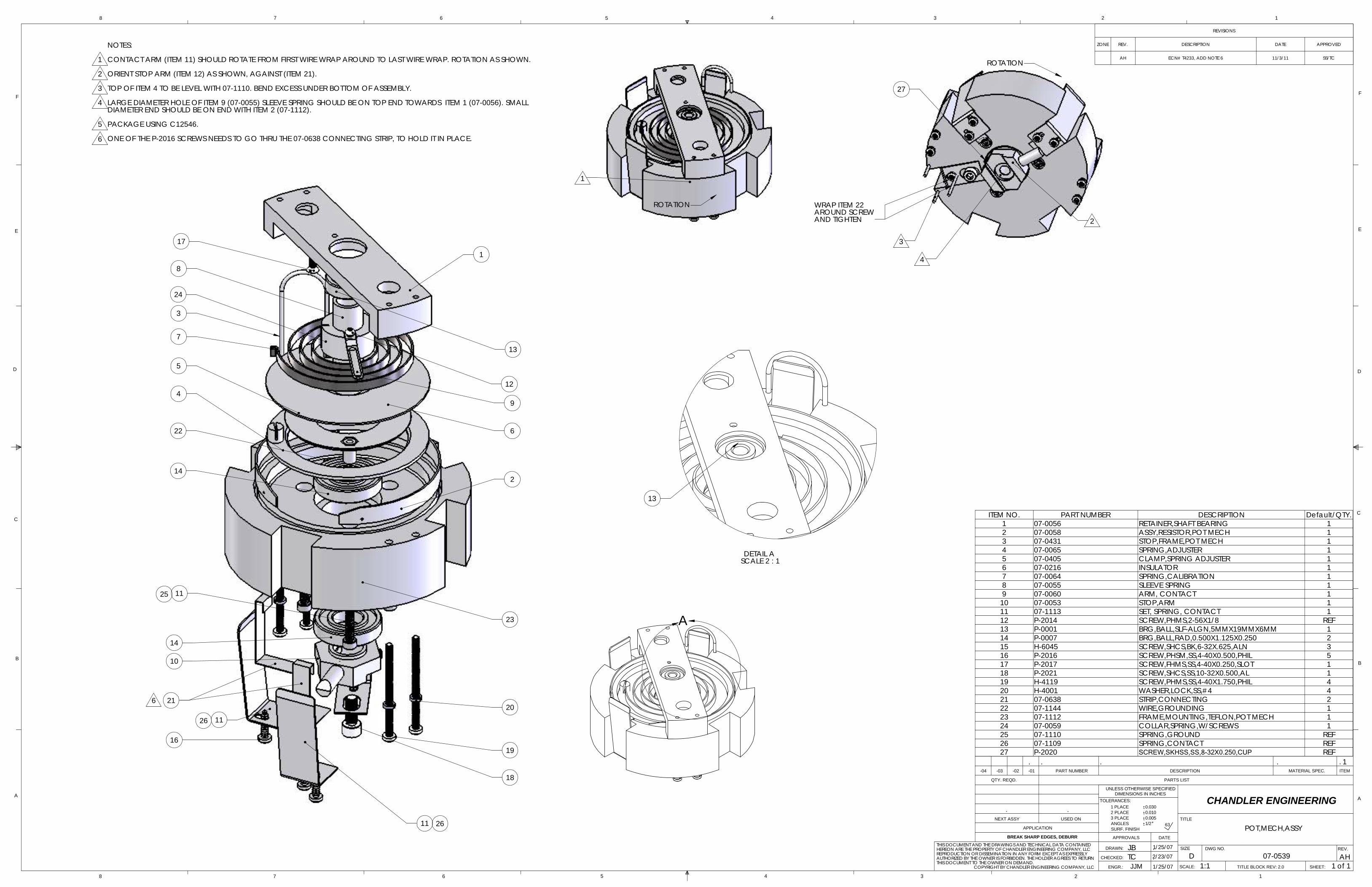
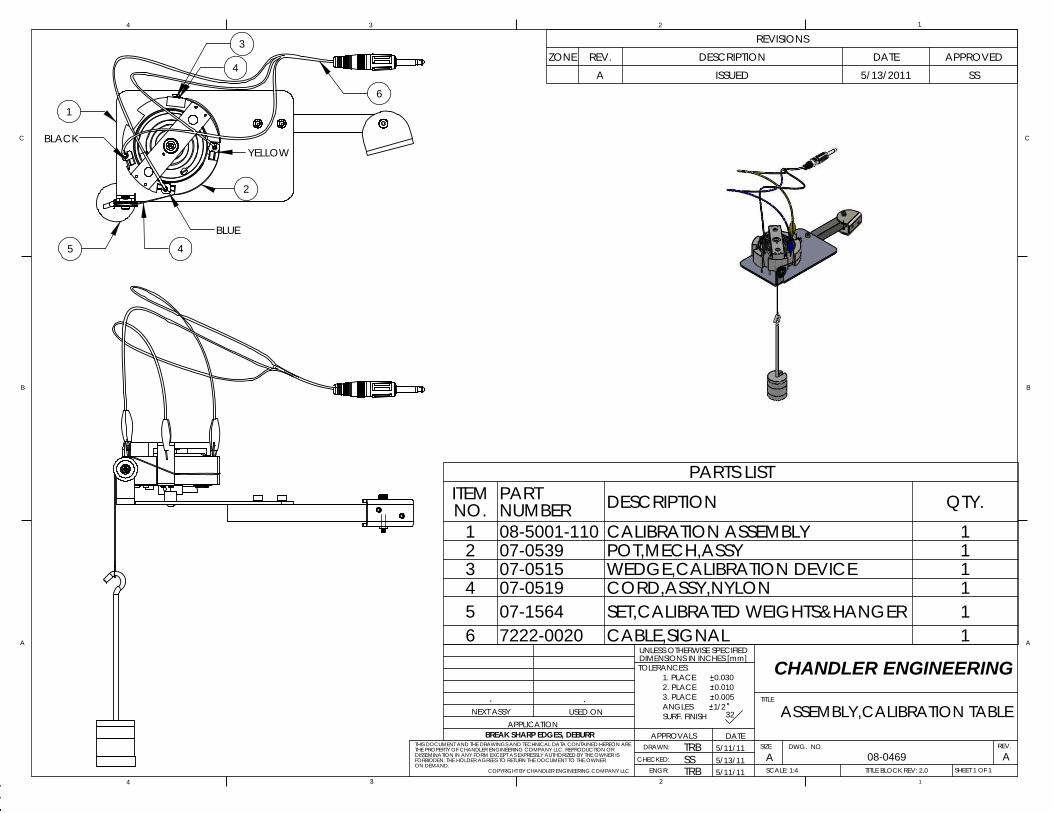
Depending on the frequency of its use, the potentiometer mechanism should be recalibrated regularly and whenever the spring, contact arm, or resistor is adjusted or replaced. Higher operating temperatures in the pressure chamber require more frequent recalibration of the potentiometer. Refer to the enclosed drawings of the calibration table assembly and Model 7322 assembly. The step-by-step calibration procedure is as follows:
1. Rotate the pot mech calibration table out to the side of the instrument. 2. Install the potentiometer on the calibration table and insert the wedge into the open slot as
shown. 3. Wrap the steel cable around the potentiometer frame and over the pulley. Place the hanger
weight hook in the cord eye. 4. Install the wire-end clips to the potentiometer tabs. (Note the wire locations.) 5. Insert the plug on the end of the calibrator wires into the calibrator socket. 6. Turn on the master switch and place 400 grams of weight on the hanger. 7. The Bearden unit gauge should read 100 Bc. (100 Bearden Units is 1 volt). The contact
points of the spring should be oiled, the weights lifted and released, and the calibrator lightly tapped to offset friction during the calibration. If the unit does not read 100 Bc, manually adjust the pot mech calibration screw located on the face panel of the top cabinet.
8. Refer to Drawing 07-0520, which is a typical calibration curve. The radius of the potentiometer mechanism is 5.2 centimeters and is multiplied by the total weight on the hanger to obtain gram centimeter torque.
9. Slurry consistency is expressed in Bearden units where 100 Bc is equivalent to the spring deflection observed with 2080 gcm of torque (400 grams weight) using the weight-loaded calibration device.
10. For further calibration details, refer to API Spec 10 booklet. This unit is supplied with weights to accommodate the full range of tests per API specs.
Magnetic Drive
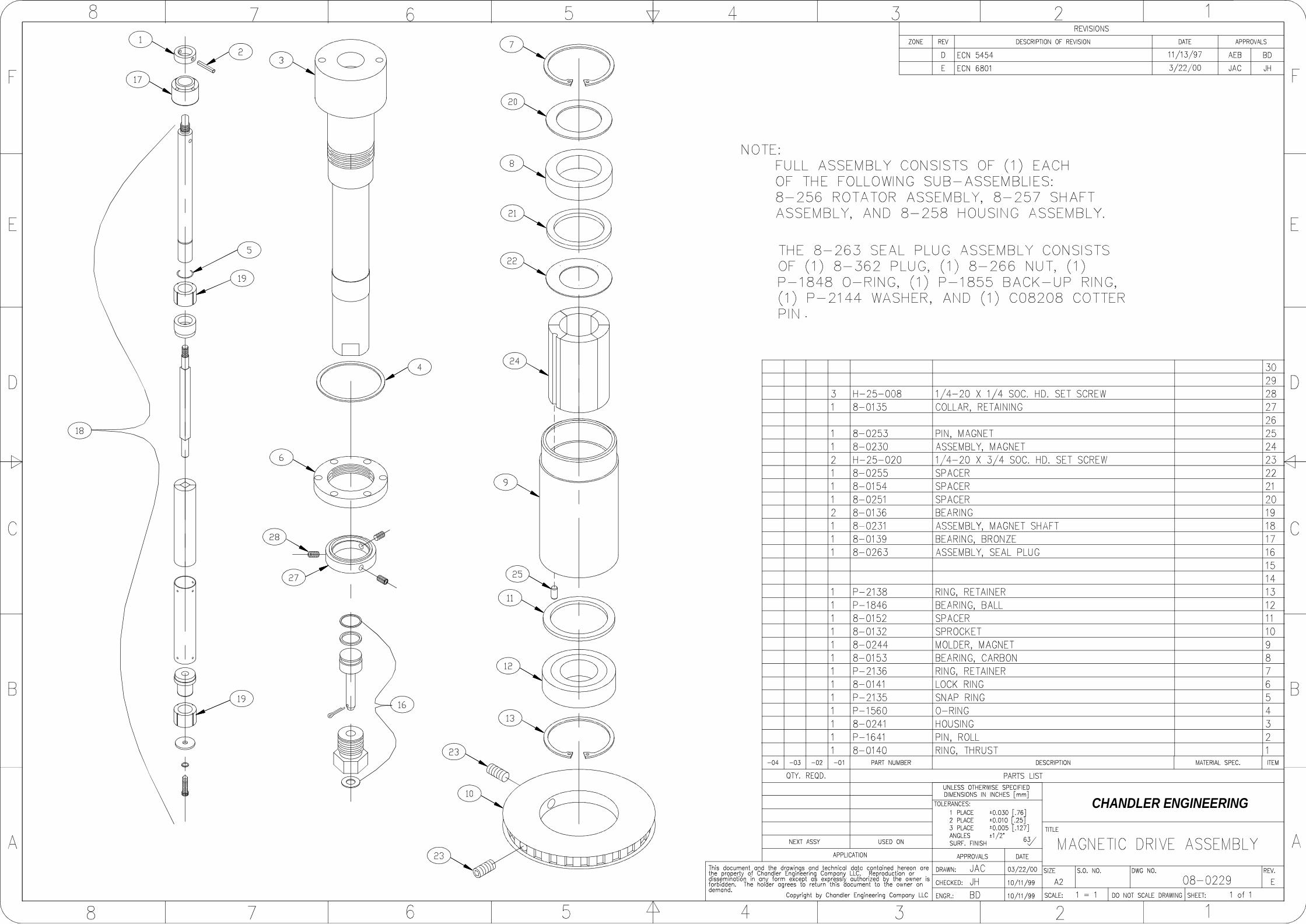
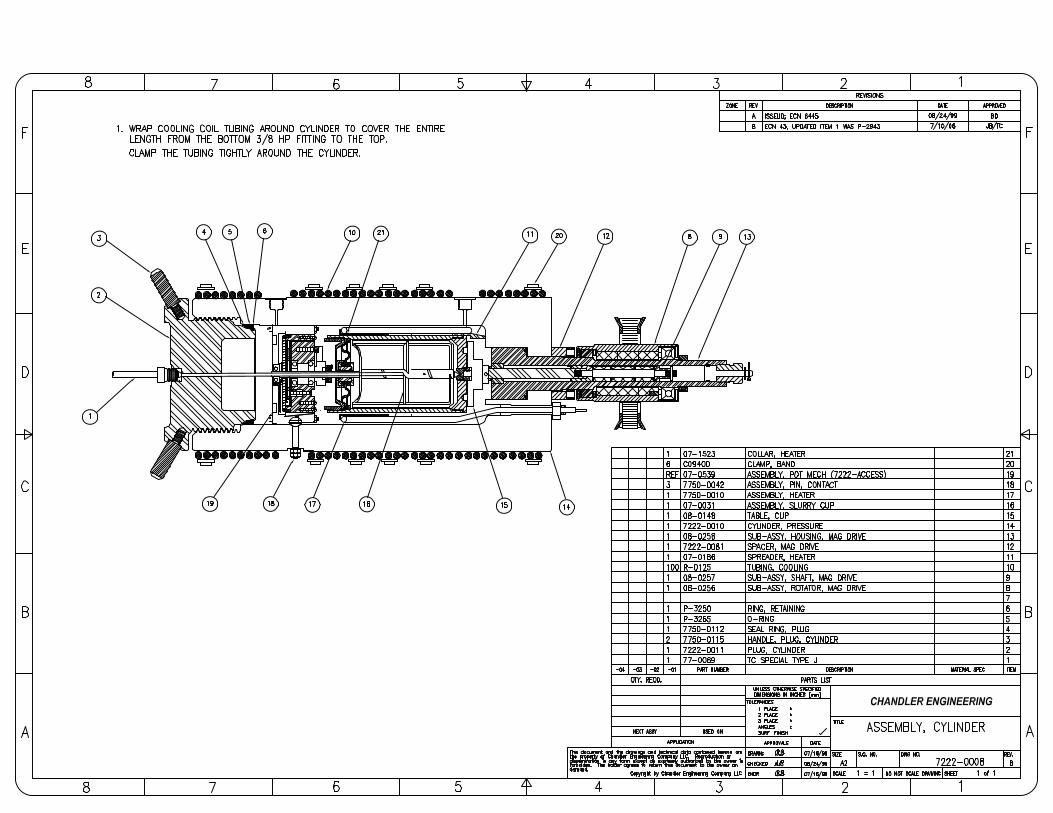
The magnetic drive should be flushed with clean water or oil whenever cement spills into the cylinder or particles contaminate the drive. More frequent flushing of the drive is required when high-temperature, high-pressure tests are run. The inner magnetic shaft must be pulled and inspected. Replace the complete assembly if the magnet sleeve is worn through or bulging at the center. Remove the magnetic housing drain plug and flush all cement sediment from the cylinder using water. Dry any remaining water on the cylinder floor using towels. Inspect and replace the following components as required.
3-4 SECTION 3 – MAINTENANCE
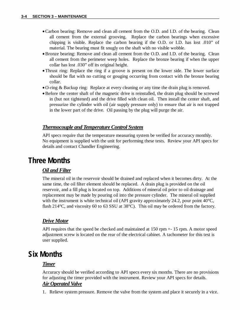
• Carbon bearing: Remove and clean all cement from the O.D. and I.D. of the bearing. Clean all cement from the external grooving. Replace the carbon bearings when excessive chipping is visible. Replace the carbon bearing if the O.D. or I.D. has lost .010” of material. The bearing must fit snugly on the shaft with no visible wobble.
• Bronze bearing: Remove and clean all cement from the O.D. and I.D. of the bearing. Clean all cement from the perimeter weep holes. Replace the bronze bearing if when the upper collar has lost .030” off its original height.
• Thrust ring: Replace the ring if a groove is present on the lower side. The lower surface should be flat with no cutting or gouging occurring from contact with the bronze bearing collar.
• O-ring & Backup ring: Replace at every cleaning or any time the drain plug is removed. • Before the center shaft of the magnetic drive is reinstalled, the drain plug should be screwed
in (but not tightened) and the drive filled with clean oil. Then install the center shaft, and pressurize the cylinder with oil (air supply pressure only) to ensure that air is not trapped in the lower part of the drive. Oil passing by the plug will purge the air.
Thermocouple and Temperature Control System
API specs require that the temperature measuring system be verified for accuracy monthly. No equipment is supplied with the unit for performing these tests. Review your API specs for details and contact Chandler Engineering.
Three Months Oil and Filter
The mineral oil in the reservoir should be drained and replaced when it becomes dirty. At the same time, the oil filter element should be replaced. A drain plug is provided on the oil reservoir, and a fill plug is located on top. Additions of mineral oil prior to oil drainage and replacement may be made by pouring oil into the pressure cylinder. The mineral oil supplied with the instrument is white technical oil (API gravity approximately 24.2, pour point 40°C, flash 214°C, and viscosity 60 to 63 SSU at 38°C). This oil may be ordered from the factory.
Drive Motor
API requires that the speed be checked and maintained at 150 rpm +- 15 rpm. A motor speed adjustment screw is located on the rear of the electrical cabinet. A tachometer for this test is user supplied.
Six Months Timer
Accuracy should be verified according to API specs every six months. There are no provisions for adjusting the timer provided with the instrument. Review your API specs for details. Air Operated Valve
1. Relieve system pressure. Remove the valve from the system and place it securely in a vice.
SECTION 3 – MAINTENANCE 3-5
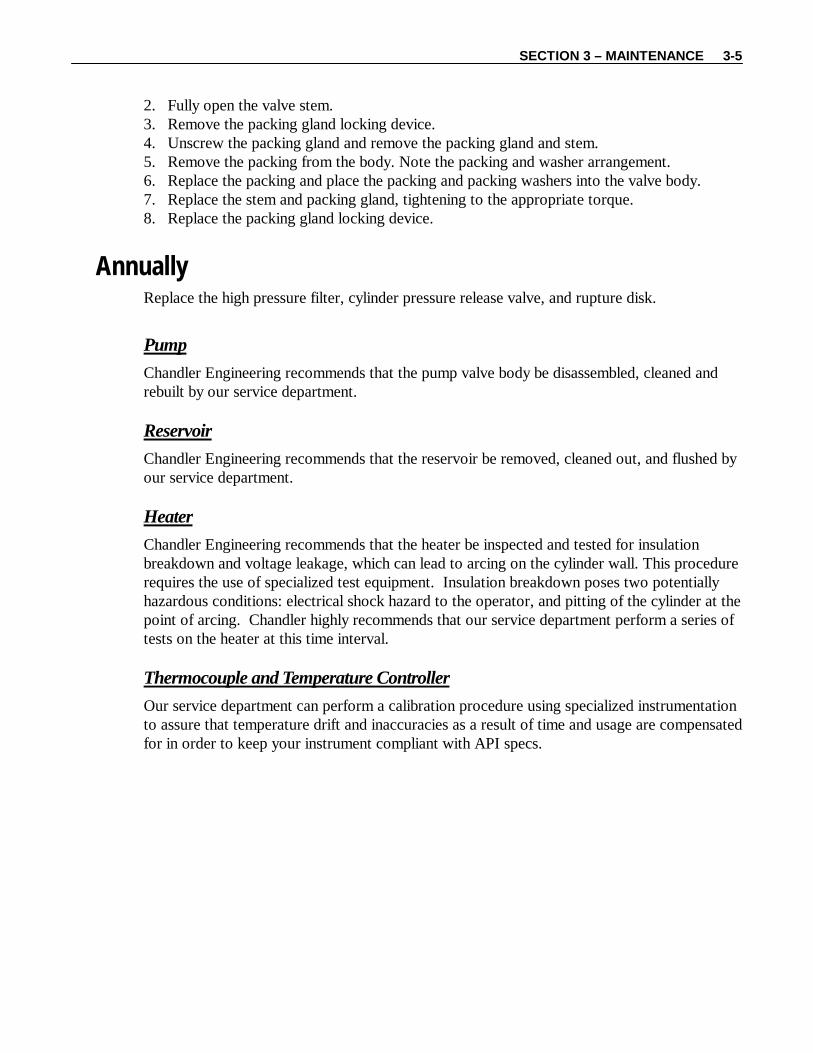
2. Fully open the valve stem. 3. Remove the packing gland locking device. 4. Unscrew the packing gland and remove the packing gland and stem. 5. Remove the packing from the body. Note the packing and washer arrangement. 6. Replace the packing and place the packing and packing washers into the valve body. 7. Replace the stem and packing gland, tightening to the appropriate torque. 8. Replace the packing gland locking device.
Annually Replace the high pressure filter, cylinder pressure release valve, and rupture disk.
Pump
Chandler Engineering recommends that the pump valve body be disassembled, cleaned and rebuilt by our service department. Reservoir
Chandler Engineering recommends that the reservoir be removed, cleaned out, and flushed by our service department. Heater
Chandler Engineering recommends that the heater be inspected and tested for insulation breakdown and voltage leakage, which can lead to arcing on the cylinder wall. This procedure requires the use of specialized test equipment. Insulation breakdown poses two potentially hazardous conditions: electrical shock hazard to the operator, and pitting of the cylinder at the point of arcing. Chandler highly recommends that our service department perform a series of tests on the heater at this time interval. Thermocouple and Temperature Controller
Our service department can perform a calibration procedure using specialized instrumentation to assure that temperature drift and inaccuracies as a result of time and usage are compensated for in order to keep your instrument compliant with API specs.
SE
CT
ION
2 –
MA
INT
EN
AN
CE
3-7
MA
INT
EN
AN
CE
SC
HE
DU
LE
C
ON
SIST
OM
ET
ER
CO
MPO
NE
NT
E
AC
H T
EST
M
ON
TH
LY
3 M
ON
TH
S 6
MO
NT
HS
AN
NU
AL
Slur
ry C
up
Dis
asse
mbl
e, C
lean
, In
spec
t
Pote
ntio
met
er M
echa
nism
C
lean
, Lub
e, In
spec
t D
isas
sem
ble,
Cle
an, L
ube,
In
spec
t
Mag
neti
c D
rive
Dis
asse
mbl
e, C
lean
, Ins
pect
Oil
R
epla
ce
Low
Pre
ssur
e Fi
lter
R
epla
ce
Cyl
inde
r Pr
ess.
Rel
ease
V
alve
R
epla
ce
Oil
-to-
Cyl
inde
r V
alve
R
epla
ce
Air
Ope
rate
d V
alve
Dis
asse
mbl
e, R
epla
ce
Nee
dle,
Sea
t
Pum
p
M
aint
aine
d B
y Q
uali
fied
Fa
ctor
y Se
rvic
e T
echn
icia
n Pr
essu
re G
auge
Cal
ibra
tion
Dri
ve M
otor
Set S
peed
Tem
p. C
ontr
olle
r T
herm
ocou
ples
(Sl
urry
and
O
il)
Insp
ect
C
alib
rati
on
Cal
ibra
te B
y Q
uali
fied
Fac
tory
Se
rvic
e T
echn
icia
n
Tim
er
Cal
ibra
tion
Hea
ter
Tes
t By
Qua
lifi
ed F
acto
ry
Serv
ice
Tec
hnic
ian
Res
ervo
ir
Cle
an-O
ut B
y Q
uali
fied
Fa
ctor
y Se
rvic
e T
echn
icia
n R
uptu
re D
isk
Rep
lace
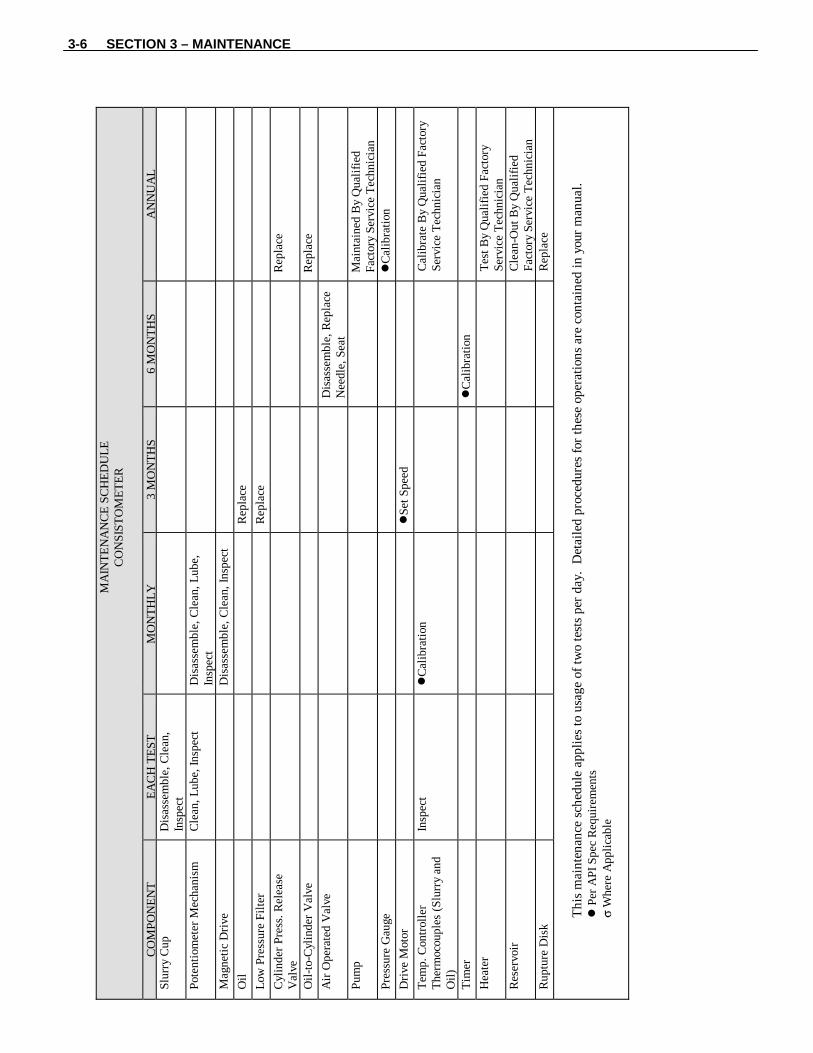
Thi
s m
aint
enan
ce s
ched
ule
appl
ies
to u
sage
of
two
test
s pe
r da
y. D
etai
led
proc
edur
es f
or th
ese
oper
atio
ns a
re c
onta
ined
in y
our
man
ual.
P
er A
PI S
pec
Req
uire
men
ts
σ W
here
App
lica
ble
3-6 SECTION 3 – MAINTENANCE
SECTION 4 – TROUBLESHOOTING GUIDE 4-1
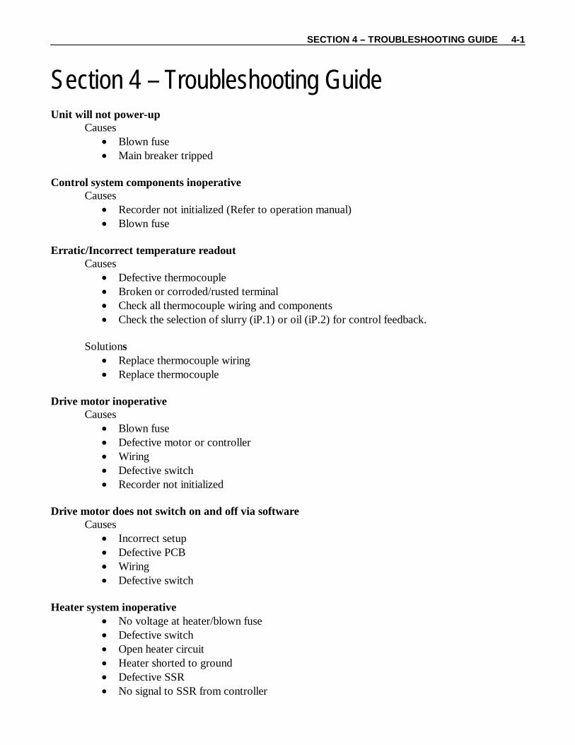
Section 4 – Troubleshooting Guide Unit will not power-up
Causes • Blown fuse • Main breaker tripped
Control system components inoperative
Causes • Recorder not initialized (Refer to operation manual) • Blown fuse
Erratic/Incorrect temperature readout
Causes • Defective thermocouple • Broken or corroded/rusted terminal • Check all thermocouple wiring and components • Check the selection of slurry (iP.1) or oil (iP.2) for control feedback.
Solutions
• Replace thermocouple wiring • Replace thermocouple
Drive motor inoperative
Causes • Blown fuse • Defective motor or controller • Wiring • Defective switch • Recorder not initialized
Drive motor does not switch on and off via software
Causes • Incorrect setup • Defective PCB • Wiring • Defective switch
Heater system inoperative
• No voltage at heater/blown fuse • Defective switch • Open heater circuit • Heater shorted to ground • Defective SSR • No signal to SSR from controller
4-2 SECTION 4 – TROUBLESHOOTING GUIDE
• Defective controller Pressure
Causes • Will not build pressure • Pressure control valve open or leaking • Pressure bleed valve open or leaking • Cylinder plug leaking • Pump malfunction • Blown rupture disk • No air at pump • Oil level low
Solutions
• Disassemble and clean air control valve body and seat per maintenance instructions • Replace stem, seat, and packing on air control valve per maintenance instructions • Close or replace pressure bleed valve • Remove cylinder plug and clean, lube, replace seal per maintenance instructions • Contact Chandler Engineering service department for pump rebuild
Plug jammed in cylinder
Causes • Failure to lubricate threads • Foreign matter in seal ring • Plug was over-tightened
Solutions
• Cool down plug and unscrew by striking handles with rubber mallet • See cylinder maintenance section
Pressure will not bleed off
Causes • Cement or other foreign material in manual valve
Solutions
• Disassemble and clean or replace valve Erratic pump action
Causes • Air lock in pump piston cavity • Contaminants in pump valve body
Solutions
• Increase air drive pressure more gradually to slow down pumping cycle • Pump must be serviced by Chandler Engineering service tech.
SECTION 4 – TROUBLESHOOTING GUIDE 4-3
Erratic Bearden Unit Readings on Recorder
Symptom: Reading drops to 0 • Pot mech resistor defective (refer to maintenance instructions) • Pot mech has disengaged from the drive bar and/or is no longer touching the
contact pins • Pot mech bearings are contaminated with cement (refer to maintenance
instructions) • Set screw on pot mech drive shaft is loose • Shear pin has broken
Solutions:
• Service pot mech per maintenance instructions • Remove pot mech, check contact pin tabs, and re-insert properly into cylinder
Symptom: Meter jumps to 10
• Contact pins shorted to cylinder

4-4 SECTION 4 – TROUBLESHOOTING GUIDE
This page is intentionally left blank.
SECTION 5 – REPLACEMENT PARTS 5-1
-7322-REPL_PARTS REV A
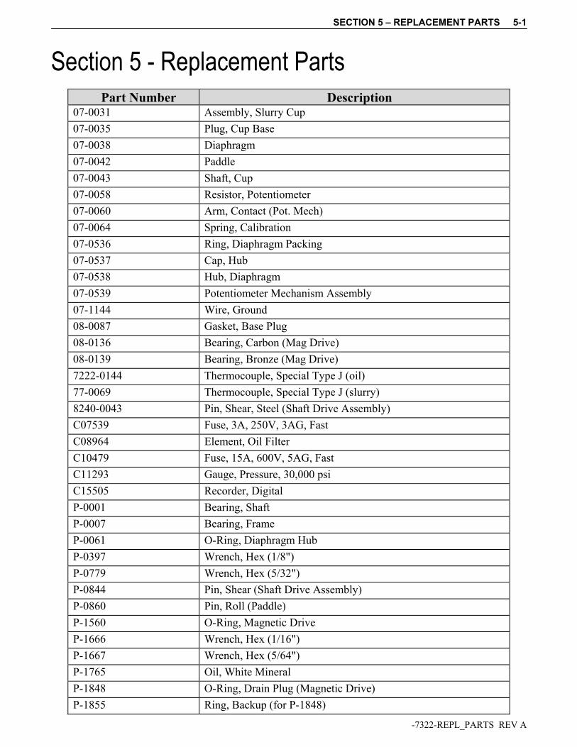
Section 5 - Replacement Parts
Part Number Description 07-0031 Assembly, Slurry Cup
07-0035 Plug, Cup Base
07-0038 Diaphragm
07-0042 Paddle
07-0043 Shaft, Cup
07-0058 Resistor, Potentiometer
07-0060 Arm, Contact (Pot. Mech)
07-0064 Spring, Calibration
07-0536 Ring, Diaphragm Packing
07-0537 Cap, Hub
07-0538 Hub, Diaphragm
07-0539 Potentiometer Mechanism Assembly
07-1144 Wire, Ground
08-0087 Gasket, Base Plug
08-0136 Bearing, Carbon (Mag Drive)
08-0139 Bearing, Bronze (Mag Drive)
7222-0144 Thermocouple, Special Type J (oil)
77-0069 Thermocouple, Special Type J (slurry)
8240-0043 Pin, Shear, Steel (Shaft Drive Assembly)
C07539 Fuse, 3A, 250V, 3AG, Fast
C08964 Element, Oil Filter
C10479 Fuse, 15A, 600V, 5AG, Fast
C11293 Gauge, Pressure, 30,000 psi
C15505 Recorder, Digital
P-0001 Bearing, Shaft
P-0007 Bearing, Frame
P-0061 O-Ring, Diaphragm Hub
P-0397 Wrench, Hex (1/8")
P-0779 Wrench, Hex (5/32")
P-0844 Pin, Shear (Shaft Drive Assembly)
P-0860 Pin, Roll (Paddle)
P-1560 O-Ring, Magnetic Drive
P-1666 Wrench, Hex (1/16")
P-1667 Wrench, Hex (5/64")
P-1765 Oil, White Mineral
P-1848 O-Ring, Drain Plug (Magnetic Drive)
P-1855 Ring, Backup (for P-1848)
SECTION 5 – REPLACEMENT PARTS 5-2
-7322-REPL_PARTS REV A
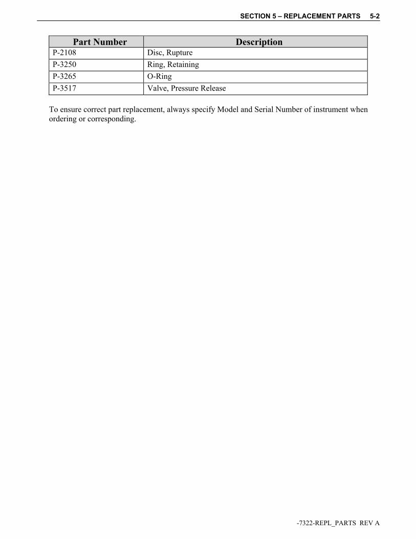
Part Number Description P-2108 Disc, Rupture
P-3250 Ring, Retaining
P-3265 O-Ring
P-3517 Valve, Pressure Release
To ensure correct part replacement, always specify Model and Serial Number of instrument when ordering or corresponding.
SECTION 6 – DRAWINGS AND SCHEMATICS 6-1
-????-DWGS REV A
Section 6 - Drawings and Schematics
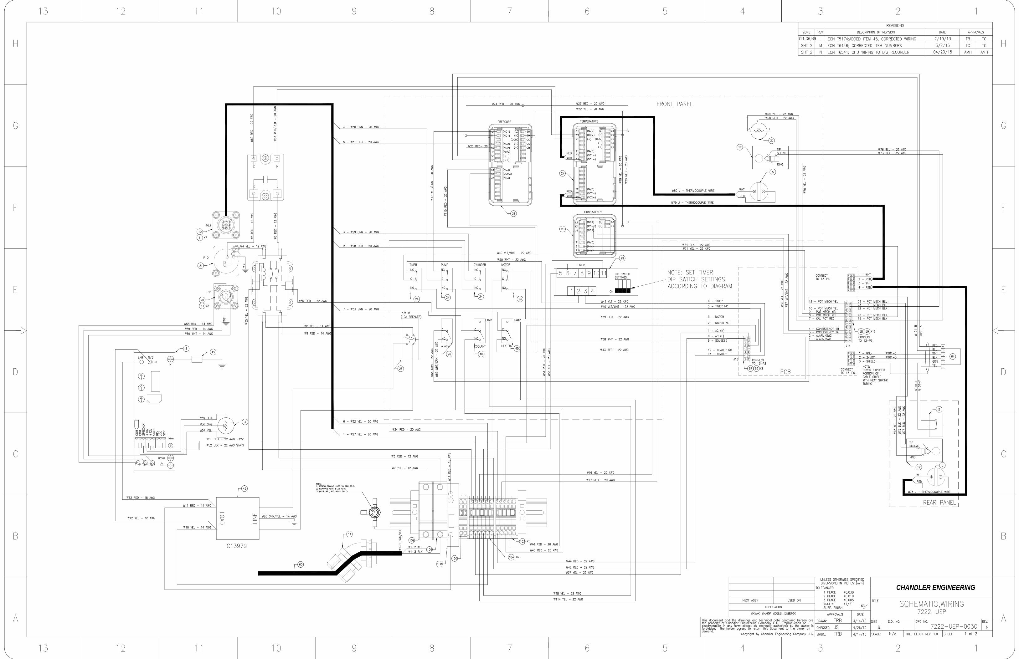
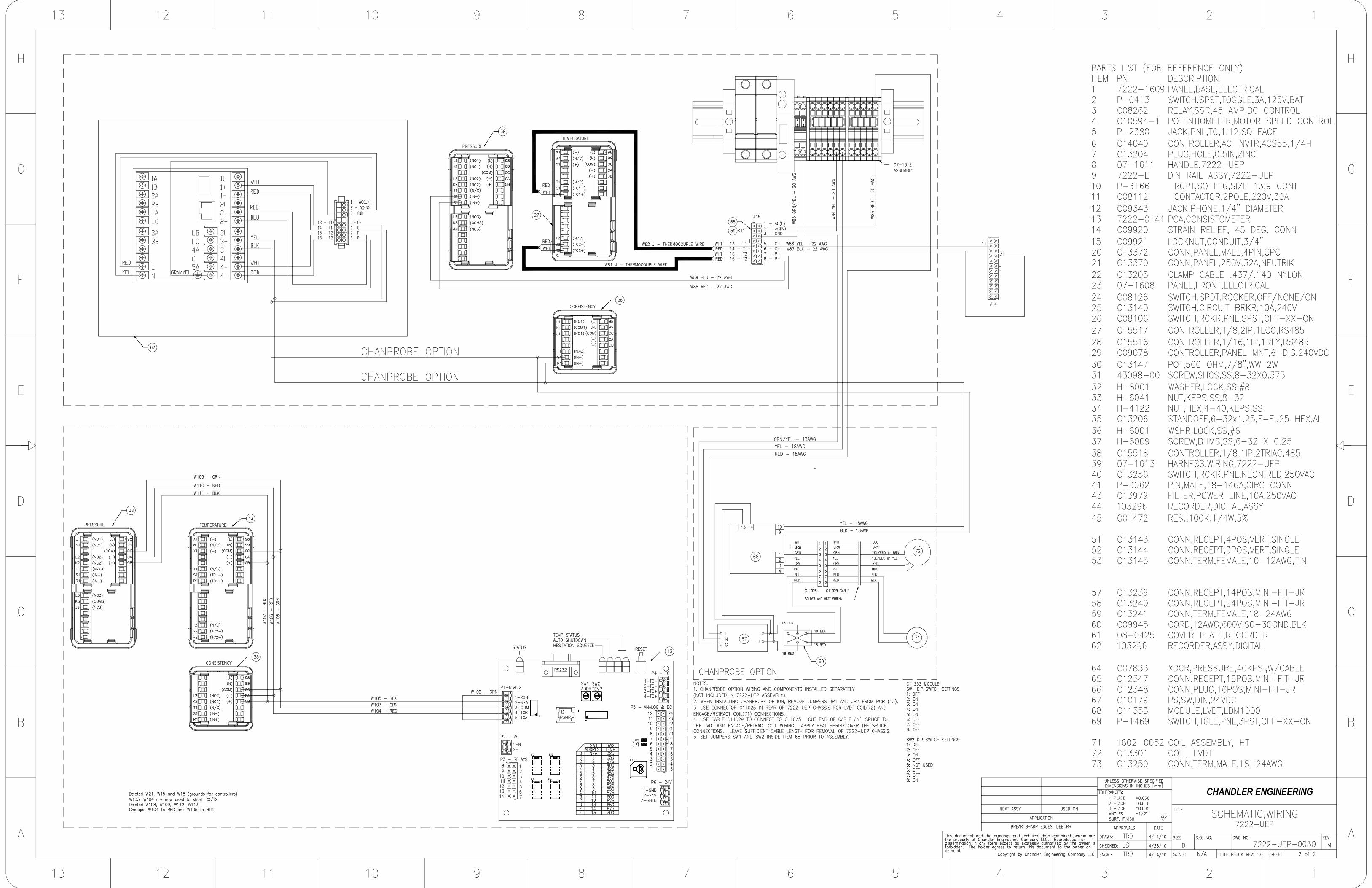
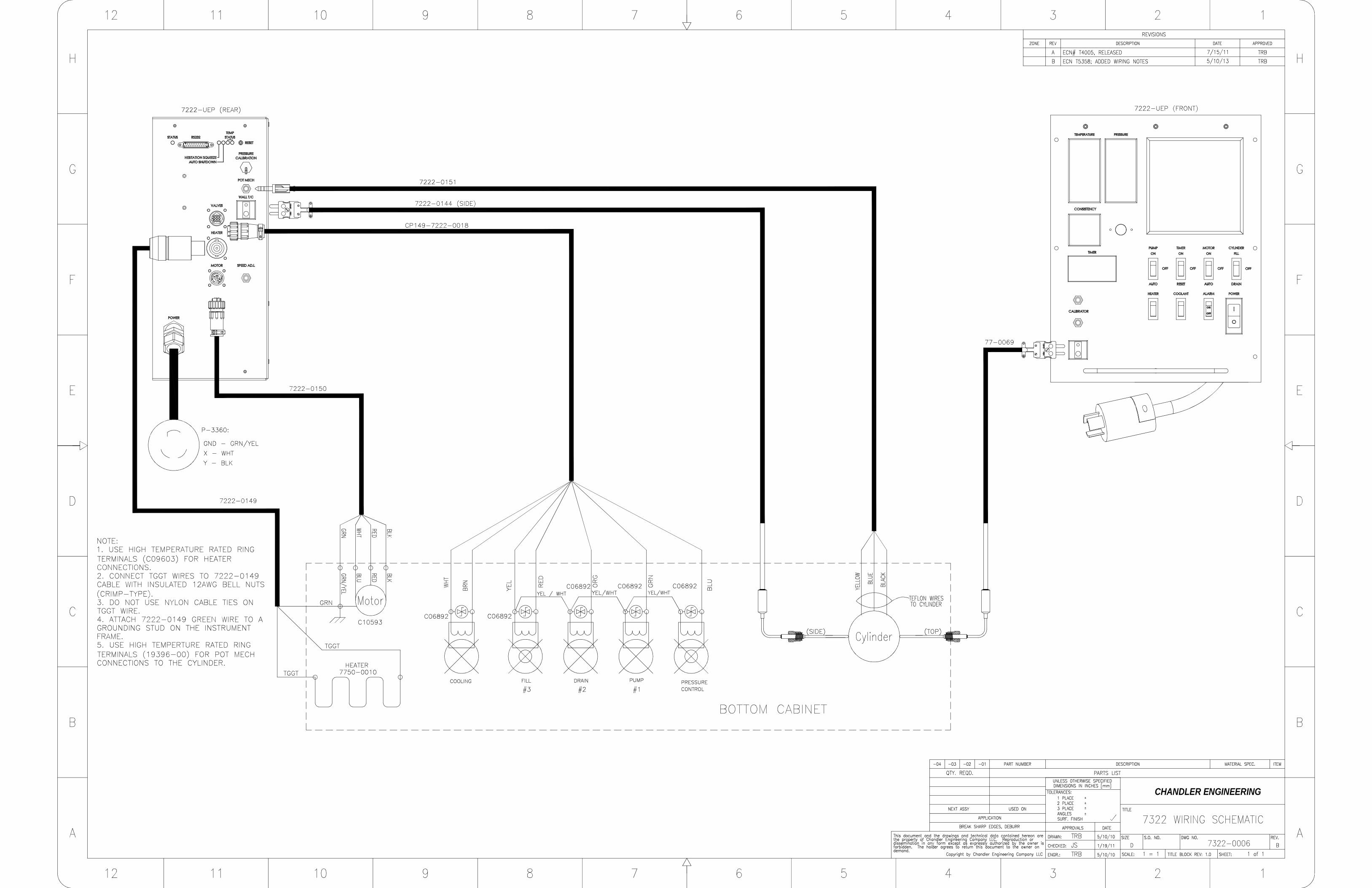
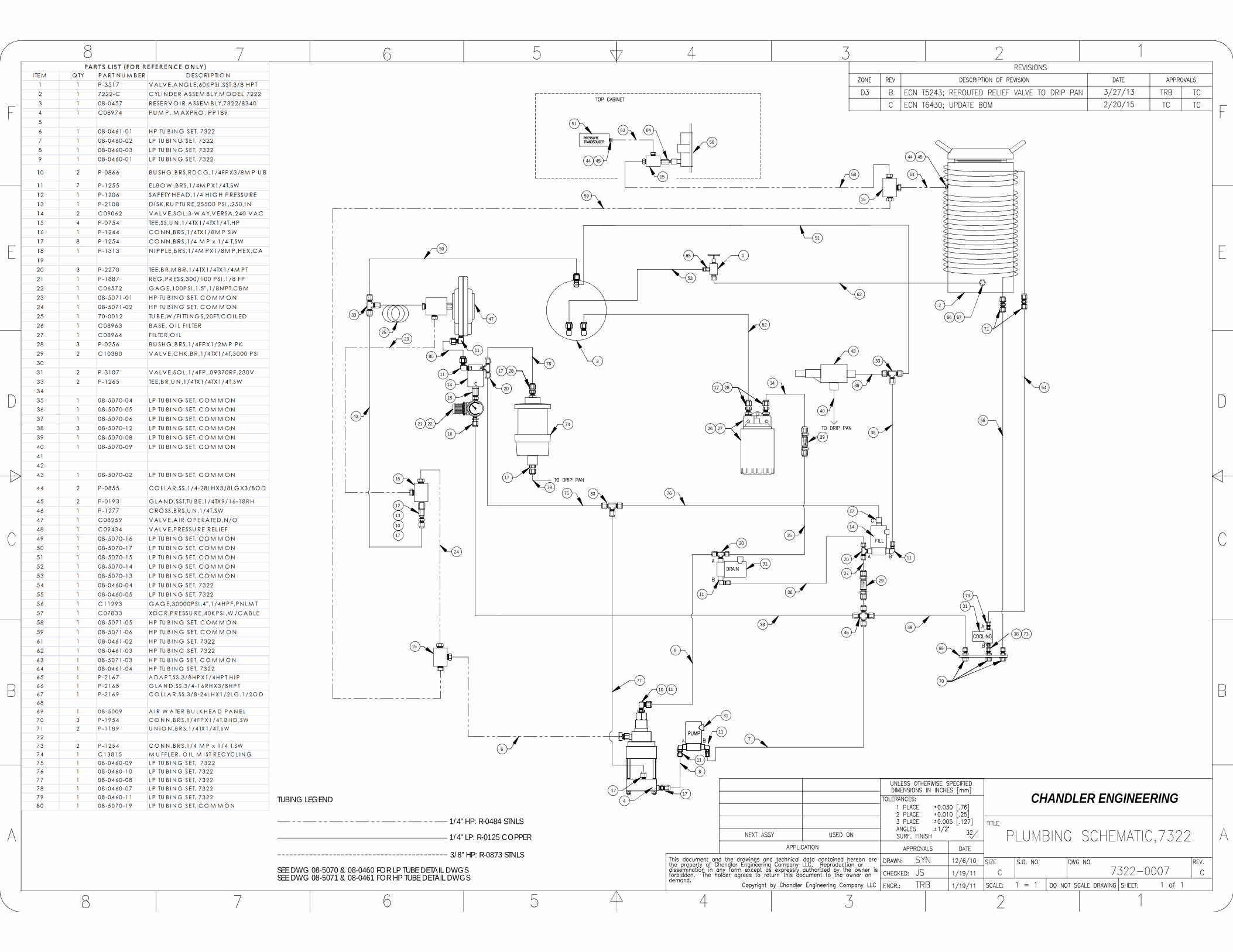
Drawing Number Description 07-0031 Slurry Cup 07-0539 Assembly, Potentiometer Mechanism 08-0229 Assembly, Magnetic Drive 08-0469 Assembly, Pot Mech Calibration Table 7222-0008 Cylinder Assembly 7222-UEP Electrical Panel 7222-UEP-0030 Electrical Schematic, 7222-UEP 7322-0006 Electrical Schematic 7322-0007 Piping Schematic
BREAK SHARP EDGES, DEBURR
TITLE BLOCK REV: 2.0
NC 07-0031
CUP,SLURRY ASSY
D
C
B
AA
B
C
D
12345678
8 7 6
. ...
5 4 3 2 1
THIS DOCUMENT TO THE OWNER ON DEMAND.
E
F
E
F
SCALE:
SIZE
TITLE
SHEET:
REV.
NEXT ASSY
APPLICATION
USED ON
ENGR.:
CHECKED:
DRAWN:
APPROVALS DATE
UNLESS OTHERWISE SPECIFIEDDIMENSIONS IN INCHES
2 PLACE
TOLERANCES:
3 PLACE
SURF. FINISH
0.030
ANGLES
0.0101 PLACE
0.005
AUTHORIZED BY THE OWNER IS FORBIDDEN. THE HOLDER AGREES TO RETURNREPRODUCTION OR DISSEMINATION IN ANY FORM EXCEPT AS EXPRESSLY
CHANDLER ENGINEERING
63
..
JBTCJJM
1/24/07
4/5/07
1/24/07 1 of 11:2
THIS DOCUMENT AND THE DRAWINGS AND TECHNICAL DATA CONTAINED HEREON ARE THE PROPERTY OF CHANDLER ENGINEERING COMPANY, LLC
1/2
DWG NO.
2
7
3. PACKAGE USING BOX C12549
NOTES:
(P-1454)
2. LUBRICATE ALL PARTS WITH WHITE LITHIUM GREASE.1. SHEAR PIN TO BE BENT UNDER DISC TO HOLD DISK AND BAR TOGETHER.
N
18
1610
14
2012
11
1
19
8
17
9
65
3
4
1
SLURRY CUP DIAPHRAGM 119 P-0860 PIN,ROLL,STL,.0625X.50 120 08-0087 COPPER GASKET 1
ITEM NO. PART NUMBER DESCRIPTION QTY.1 07-0043 CUP SHAFT 12 P-0844 PIN,SHEAR,BRS,0.035x0.50L 13 07-0046 DRIVE SHAFT BAR 14 07-0045 DRIVE SHAFT DISK 15 07-0036 CUP LOCK RING 16 07-0039 DIAPHRAGM SUPPORT 17 P-0061 ORING 28 07-0037 COLLAR 19 07-0537 HUB CAP 110 07-0042 PADDLE 111 07-0032 TAPERED SLURRY CUP 112 07-0033 SLURRY CUP BASE 114 07-0035 BASE PLUG PLUG 116 07-0538 HUB DIAPHRAGM 117 07-0536 PACKING RING 118 07-0038
REVISIONS
ZONE REV. DESCRIPTION DATE APPROVED
N ECN T1824; ADDED NOTE 3, CORRECTED ITEM NUMBERS 8/14/2008 TC
1
1:1
. .
. .JJM 1/25/07
D
C
B
AA
B
C
D
12345678
8 7 6 5 4 3 2 1
E
F
E
.
F
.ITEM
63
ENGR.:
CHANDLER ENGINEERING
SCALE:
1/20.0050.0100.030
3 PLACE2 PLACE1 PLACE
ANGLESSURF. FINISH
TOLERANCES:DIMENSIONS IN INCHES
UNLESS OTHERWISE SPECIFIED
DATEAPPROVALS
DRAWN:
CHECKED:
USED ON
BREAK SHARP EDGES, DEBURR
NEXT ASSY
MATERIAL SPEC.DESCRIPTION-02 -01-04 -03
SHEET: 1 of 1
.. .
QTY. REQD.
PART NUMBER
PARTS LIST
REV.DWG NO.
TITLE
SIZE
COPYRIGHT BY CHANDLER ENGINEERING COMPANY, LLC
TC 2/23/071/25/07JB
. .
APPLICATION
TITLE BLOCK REV: 2.0
D 07-0539 AH
THIS DOCUMENT AND THE DRAWINGS AND TECHNICAL DATA CONTAINED HEREON ARE THE PROPERTY OF CHANDLER ENGINEERING COMPANY, LLC REPRODUCTION OR DISSEMINATION IN ANY FORM EXCEPT AS EXPRESSLYAUTHORIZED BY THE OWNER IS FORBIDDEN. THE HOLDER AGREES TO RETURNTHIS DOCUMENT TO THE OWNER ON DEMAND.
POT,MECH,ASSY
ITEM NO. PART NUMBER DESCRIPTION Default/QTY.1 07-0056 RETAINER,SHAFT BEARING 12 07-0058 ASSY,RESISTOR,POT MECH 13 07-0431 STOP,FRAME,POT MECH 14 07-0065 SPRING,ADJUSTER 15 07-0405 CLAMP,SPRING ADJUSTER 16 07-0216 INSULATOR 17 07-0064 SPRING,CALIBRATION 18 07-0055 SLEEVE SPRING 19 07-0060 ARM, CONTACT 1
10 07-0053 STOP,ARM 111 07-1113 SET, SPRING, CONTACT 112 P-2014 SCREW,PHMS,2-56X1/8 REF13 P-0001 BRG,BALL,SLF-ALGN,5MMX19MMX6MM 114 P-0007 BRG,BALL,RAD,0.500X1.125X0.250 215 H-6045 SCREW,SHCS,BK,6-32X.625,ALN 316 P-2016 SCREW,PHSM,SS,4-40X0.500,PHIL 517 P-2017 SCREW,FHMS,SS,4-40X0.250,SLOT 118 P-2021 SCREW,SHCS,SS,10-32X0.500,AL 119 H-4119 SCREW,PHMS,SS,4-40X1.750,PHIL 420 H-4001 WASHER,LOCK,SS,#4 421 07-0638 STRIP,CONNECTING 222 07-1144 WIRE,GROUNDING 123 07-1112 FRAME,MOUNTING,TEFLON,POT MECH 124 07-0059 COLLAR,SPRING,W/SCREWS 125 07-1110 SPRING,GROUND REF26 07-1109 SPRING,CONTACT REF27 P-2020 SCREW,SKHSS,SS,8-32X0.250,CUP REF
REVISIONS
ZONE REV. DESCRIPTION DATE APPROVED
AH ECN# T4233, ADD NOTE 6 11/3/11 SS/TC
25
26
26
A
2
3
ROTATION
27
4
WRAP ITEM 22AROUND SCREWAND TIGHTEN
1
ROTATION
5
6
1
2
3
4
6
24
17
13
1
9
6
8
2
23
19
18
16
10
14
20
4
3
7
5
22
PACKAGE USING C12546.
LARGE DIAMETER HOLE OF ITEM 9 (07-0055) SLEEVE SPRING SHOULD BE ON TOP END TOWARDS ITEM 1 (07-0056). SMALL
TOP OF ITEM 4 TO BE LEVEL WITH 07-1110. BEND EXCESS UNDER BOTTOM OF ASSEMBLY.
ONE OF THE P-2016 SCREWS NEEDS TO GO THRU THE 07-0638 CONNECTING STRIP, TO HOLD IT IN PLACE.
DIAMETER END SHOULD BE ON END WITH ITEM 2 (07-1112).
14
21
11
11
11
NOTES:
CONTACT ARM (ITEM 11) SHOULD ROTATE FROM FIRST WIRE WRAP AROUND TO LAST WIRE WRAP. ROTATION AS SHOWN.
ORIENT STOP ARM (ITEM 12) AS SHOWN, AGAINST (ITEM 21).
12
DETAIL A SCALE 2 : 1
13
CHANDLER ENGINEERING
BLACK
6
BLUE
3
4
4
1
2
5
YELLOW
REVISIONSZONE REV. DESCRIPTION DATE APPROVED
A ISSUED 5/13/2011 SS
PARTS LISTITEM NO.
PART NUMBER DESCRIPTION QTY.
1 08-5001-110 CALIBRATION ASSEMBLY 12 07-0539 POT,MECH,ASSY 13 07-0515 WEDGE,CALIBRATION DEVICE 14 07-0519 CORD,ASSY,NYLON 15 07-1564 SET,CALIBRATED WEIGHTS&HANGER 16 7222-0020 CABLE,SIGNAL 1
ASSEMBLY,CALIBRATION TABLE
UNLESS OTHERWISE SPECIFIED
5/11/11FORBIDDEN. THE HOLDER AGREES TO RETURN THE DOCUMENT TO THE OWNER
.NEXT ASSY
SCALE: 1:4
SIZETRB
SURF. FINISH
ON DEMAND.
DIMENSIONS IN INCHES [mm]
SS
.32
THE PROPERTY OF CHANDLER ENGINEERING COMPANY LLC. REPRODUCTION ORDISSEMINATION IN ANY FORM EXCEPT AS EXPRESSLY AUTHORIZED BY THE OWNER IS
COPYRIGHT BY CHANDLER ENGINEERING COMPANY LLC
TITLE
APPROVALS DATE
1234
1234
A
B
CC
B
A
CHECKED:
DRAWN:
ENGR:
...
.
.
.
.
DWG. NO.
APPLICATION
.
BREAK SHARP EDGES, DEBURR
A5/13/11TRB
08-04695/11/11 REV.
CHANDLER ENGINEERING
SHEET 1 OF 1
ATHIS DOCUMENT AND THE DRAWINGS AND TECHNICAL DATA CONTAINED HEREON ARE
TITLE BLOCK REV: 2.0
TOLERANCES: 1. PLACE 0.030 2. PLACE 0.010 3. PLACE 0.005 ANGLES 1/2USED ON
DESCRIPTIONREV.ZONE
REVISIONS
TC3/11/14ECN T5809; ADDED 2 EA C13800F
TRB2/19/13NOTESECN T5174; UPDATED COMPONENTS, ADDED #45 AND E
TRB9/18/12ECN T4894; CHANGED CONTROLLERS AND RECORDERD
SS/TRB10/27/11ECN# T4222, REPLACE ITEMS 6 AND 43C
APPROVEDDATE
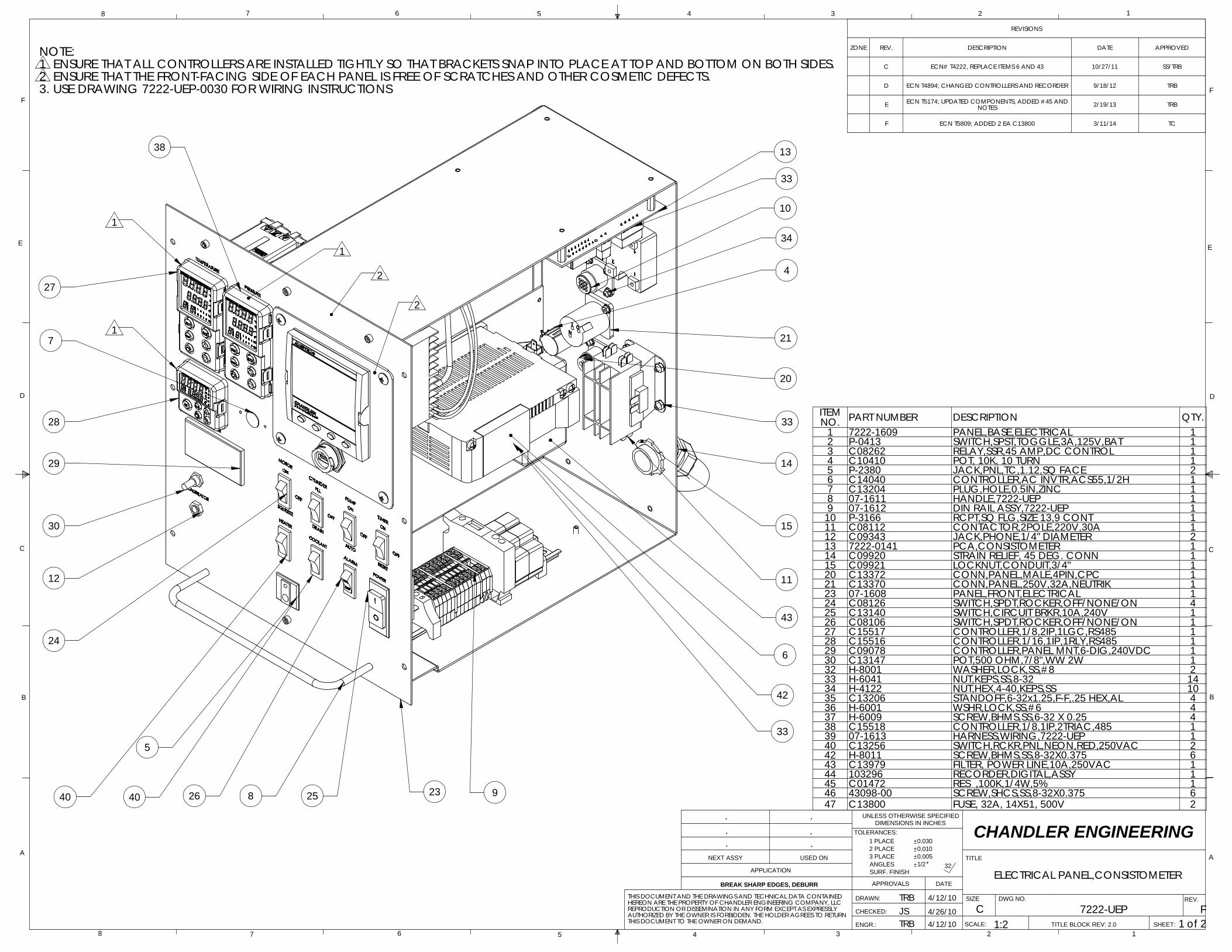
ITEM NO. PART NUMBER DESCRIPTION QTY.
1 7222-1609 PANEL,BASE,ELECTRICAL 12 P-0413 SWITCH,SPST,TOGGLE,3A,125V,BAT 13 C08262 RELAY,SSR,45 AMP,DC CONTROL 14 C10410 POT, 10K, 10 TURN 15 P-2380 JACK,PNL,TC,1.12,SQ FACE 26 C14040 CONTROLLER,AC INVTR,ACS55,1/2H 17 C13204 PLUG,HOLE,0.5IN,ZINC 18 07-1611 HANDLE,7222-UEP 19 07-1612 DIN RAIL ASSY,7222-UEP 1
10 P-3166 RCPT,SQ FLG,SIZE 13,9 CONT 111 C08112 CONTACTOR,2POLE,220V,30A 112 C09343 JACK,PHONE,1/4" DIAMETER 213 7222-0141 PCA,CONSISTOMETER 114 C09920 STRAIN RELIEF, 45 DEG. CONN 115 C09921 LOCKNUT,CONDUIT,3/4" 120 C13372 CONN,PANEL,MALE,4PIN,CPC 121 C13370 CONN,PANEL,250V,32A,NEUTRIK 123 07-1608 PANEL,FRONT,ELECTRICAL 124 C08126 SWITCH,SPDT,ROCKER,OFF/NONE/ON 425 C13140 SWITCH,CIRCUIT BRKR,10A,240V 126 C08106 SWITCH,SPDT,ROCKER,OFF/NONE/ON 127 C15517 CONTROLLER,1/8,2IP,1LGC,RS485 128 C15516 CONTROLLER,1/16,1IP,1RLY,RS485 129 C09078 CONTROLLER,PANEL MNT,6-DIG,240VDC 130 C13147 POT,500 OHM,7/8",WW 2W 132 H-8001 WASHER,LOCK,SS,#8 233 H-6041 NUT,KEPS,SS,8-32 1434 H-4122 NUT,HEX,4-40,KEPS,SS 1035 C13206 STANDOFF,6-32x1.25,F-F,.25 HEX,AL 436 H-6001 WSHR,LOCK,SS,#6 437 H-6009 SCREW,BHMS,SS,6-32 X 0.25 438 C15518 CONTROLLER,1/8,1IP,2TRIAC,485 139 07-1613 HARNESS,WIRING,7222-UEP 140 C13256 SWITCH,RCKR,PNL,NEON,RED,250VAC 242 H-8011 SCREW,BHMS,SS,8-32X0.375 643 C13979 FILTER, POWER LINE,10A,250VAC 144 103296 RECORDER,DIGITAL,ASSY 145 C01472 RES ,100K,1/4W,5% 146 43098-00 SCREW,SHCS,SS,8-32X0.375 647 C13800 FUSE, 32A, 14X51, 500V 2
ELECTRICAL PANEL,CONSISTOMETER
.
JS 4/26/10TRB 4/12/10
D
C
B
AA
B
C
D
12345678
8 7 6
DWG NO.
C FTITLE BLOCK REV: 2.0
5 4 3 2 1
THIS DOCUMENT TO THE OWNER ON DEMAND.
E
F
E
F
SCALE:
SIZE
TITLE
SHEET:
REV.
NEXT ASSY
APPLICATION
USED ON
ENGR.:
CHECKED:
DRAWN:
APPROVALS DATE
UNLESS OTHERWISE SPECIFIEDDIMENSIONS IN INCHES
2 PLACE
TOLERANCES:
3 PLACE
SURF. FINISH
0.030
ANGLES
0.0101 PLACE
0.005
AUTHORIZED BY THE OWNER IS FORBIDDEN. THE HOLDER AGREES TO RETURN
4/12/10REPRODUCTION OR DISSEMINATION IN ANY FORM EXCEPT AS EXPRESSLY
32
..
1 of 21:2
. CHANDLER ENGINEERING.
.
TRBBREAK SHARP EDGES, DEBURR
THIS DOCUMENT AND THE DRAWINGS AND TECHNICAL DATA CONTAINED HEREON ARE THE PROPERTY OF CHANDLER ENGINEERING COMPANY, LLC
1/2
7222-UEP
1
13
10
4
21
20
14
11
925826
5
24
12
30
29
28
7
38
27
34
33
33
40 40 23
42
15
2
6
33
2
3. USE DRAWING 7222-UEP-0030 FOR WIRING INSTRUCTIONS2 ENSURE THAT THE FRONT-FACING SIDE OF EACH PANEL IS FREE OF SCRATCHES AND OTHER COSMETIC DEFECTS.1 ENSURE THAT ALL CONTROLLERS ARE INSTALLED TIGHTLY SO THAT BRACKETS SNAP INTO PLACE AT TOP AND BOTTOM ON BOTH SIDES.NOTE:
43
1
1
35
C
C
D
C
B
AA
B
C
D
12345678
8 7 6 5 4 3 2 1
THIS DOCUMENT AND THE DRAWINGS AND TECHNICAL DATA CONTAINED HEREON ARE THE PROPERTY OF CHANDLER ENGINEERING COMPANY, LLCREPRODUCTION OR DISSEMINATION IN ANY FORM EXCEPT AS EXPRESSLYAUTHORIZED BY THE OWNER IS FORBIDDEN. THE HOLDER AGREES TO RETURNTHIS DOCUMENT TO THE OWNER ON DEMAND.
E
F
E
F
SCALE:
SIZE
TITLE
SHEET:
REV.
NEXT ASSY
APPLICATION
USED ON
ENGR.:
CHECKED:
DRAWN:
APPROVALS DATE
UNLESS OTHERWISE SPECIFIEDDIMENSIONS IN INCHES
TOLERANCES:
SURF. FINISHANGLES
1 PLACE2 PLACE3 PLACE
0.0300.0100.0051/2
CHANDLER ENGINEERING
32
..
2 of 21:4
. ...
BREAK SHARP EDGES, DEBURR
TITLE BLOCK REV: 2.0
FCDWG NO.
ELECTRICAL PANEL,CONSISTOMETER
TRB 4/12/10
JS 4/26/10TRB 4/12/10
7222-UEP
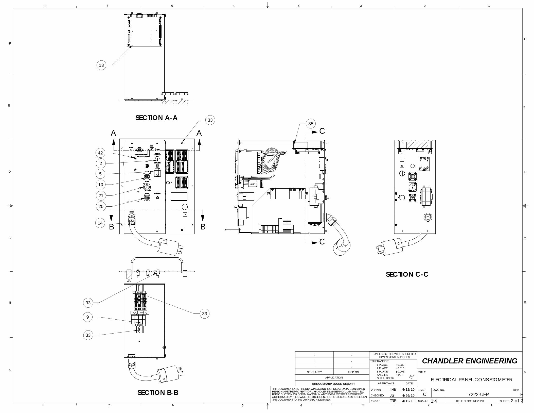
SECTION A-A
13
2
14
20
21
10
33
42
5
A A
B B
33
SECTION B-B
9
33
33
SECTION C-C
CHANDLER ENGINEERING
CHANDLER ENGINEERING
CHANDLER ENGINEERING
1
71
44 45
66 67
61
54
55
73
11
11
31
1110
9
8
7
6
2
74
44
69
31
733846
45
64
50
43
39
38
34
35
36
38
37
49
62
65
53
23
24
16
18
29
33
33
26 27
17 28
20
20
20
25
47
48
15
15
14
17
10
13
12
21 22
11
11
57
59
31
70
52
51
63
15
56
58
15
3
TUBING LEGEND
3/8" HP: R-0873 STNLS
1/4" LP: R-0125 COPPER
1/4" HP: R-0484 STNLS
SEE DWG 08-5070 & 08-0460 FOR LP TUBE DETAIL DWGSSEE DWG 08-5071 & 08-0461 FOR HP TUBE DETAIL DWGS
3375 76
77
17
14
17
17 28
17
78
79
4
17
11
1180
29
40
CHANDLER ENGINEERING
AEROSPACE & DEFENSE
2001 North Indianwood Avenue, Broken Arrow, OK 74012 Phone: 918-250-7200 Fax: 918-459-0165
© 2008, by AMETEK, Inc. All rights reserved. e-mail: [email protected] www.chandlereng.com
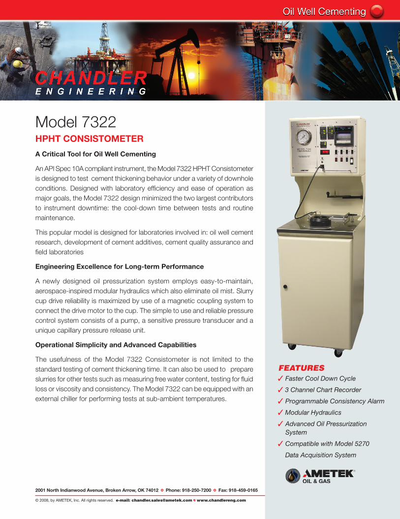
Model 7322HPHT CONSISTOMETER
A Critical Tool for Oil Well Cementing
An API Spec 10A compliant instrument, the Model 7322 HPHT Consistometer is designed to test cement thickening behavior under a variety of downhole conditions. Designed with laboratory efficiency and ease of operation as major goals, the Model 7322 design minimized the two largest contributors to instrument downtime: the cool-down time between tests and routine maintenance.
This popular model is designed for laboratories involved in: oil well cement research, development of cement additives, cement quality assurance and field laboratories
Engineering Excellence for Long-term Performance
A newly designed oil pressurization system employs easy-to-maintain, aerospace-inspired modular hydraulics which also eliminate oil mist. Slurry cup drive reliability is maximized by use of a magnetic coupling system to connect the drive motor to the cup. The simple to use and reliable pressure control system consists of a pump, a sensitive pressure transducer and a unique capillary pressure release unit.
Operational Simplicity and Advanced Capabilities
The usefulness of the Model 7322 Consistometer is not limited to the standard testing of cement thickening time. It can also be used to prepare slurries for other tests such as measuring free water content, testing for fluid loss or viscosity and consistency. The Model 7322 can be equipped with an external chiller for performing tests at sub-ambient temperatures.
FEATURES3 Faster Cool Down Cycle
3 3 Channel Chart Recorder
3 Programmable Consistency Alarm
3 Modular Hydraulics
3 Advanced Oil Pressurization System
3 Compatible with Model 5270
Data Acquisition System
Printed in the U.S.A. © 2008, by AMETEK, Inc. All rights reserved. XM808PDF (360000)
2001 North Indianwood Avenue, Broken Arrow, OK 74012 Tel: +1 918-250-7200 Fax: +1 918-459-0165e-mail: [email protected] www.chandlereng.com
Houston Sales and Services4903 W. Sam Houston Parkway, N., Suite A-400, Houston, TX 77041 Tel: +1 713-466-4900 Fax: +1 713-849-1924
Specifications
Maximum Temperature 400ºF (204ºC)
Maximum Pressure 22,000 psi (150 MPa)
Heater Power 2,200 Watts
Slurry Cup Rotation Speed 150 rpm
Thickening Time Range 0 to 100 Bc (Bearden Units)
Operating Temperature Ambient to 120ºF (50ºC)
Turn-around Time 20 minutes typical
Pressure Medium White Mineral Oil
Data Acquisition Three channel strip chart recorder Chandler Engineering Model 5270 Data Acquisition and Control Software for a stand-alone computer (optional)
UtilitiesMains 208-240 VAC, 20A, 50/60 HZ, 1 Phase
Water 20-80 psi (150 – 600 kPa)
Air 50-100 psi (350 – 700 kPa)
Physical Dimensions Dimensions (w x d x h) 23 in x 28 in x 73 in (57 cm x 71 cm x 186 cm)
Weight 570 lb (259 kg)
Compliance API Spec 10A / ISO 10426-1
R0211.001
Manufacturer’s specifications subject to change without notice
Revision 1: August 22, 2014