Embed Size (px)
Citation preview
Great Planes® Model Manufacturing Co. guarantees this kit to be free from defects in both material and workmanship at the date of purchase. This warranty does not cover any component parts damaged by use or modifi cation. In no case shall Great Planes’ liability exceed the original cost of the purchased kit. Further, Great Planes reserves the right to change or modify this warranty without notice.
In that Great Planes has no control over the fi nal assembly or material used for fi nal assembly, no liability shall be assumed nor accepted for any damage resulting from the use by the user of the fi nal user-assembled product. By the act of using the user-assembled product, the user accepts all resulting liability.
If the buyer is not prepared to accept the liability associated with the use of this product, the buyer is advised to return
this kit immediately in new and unused condition to the place of purchase.
To make a warranty claim send the defective part or item to Hobby Services at the address below:
Hobby Services3002 N. Apollo Dr., Suite 1Champaign, IL 61822 USA
Include a letter stating your name, return shipping address, as much contact information as possible (daytime telephone number, fax number, e-mail address), a detailed description of the problem and a photocopy of the purchase receipt. Upon receipt of the package, the problem will be evaluated as quickly as possible.
READ THROUGH THIS MANUAL BEFORE STARTING CONSTRUCTION. IT CONTAINS IMPORTANT INSTRUCTIONS AND WARNINGS CONCERNING THE ASSEMBLY AND USE OF THIS MODEL.
Champaign, Illinois(217) 398-8970, Ext 5
WARRANTY
INSTRUCTION MANUAL
Entire Contents © Copyright 2008 GPMA1022Mnl1.0
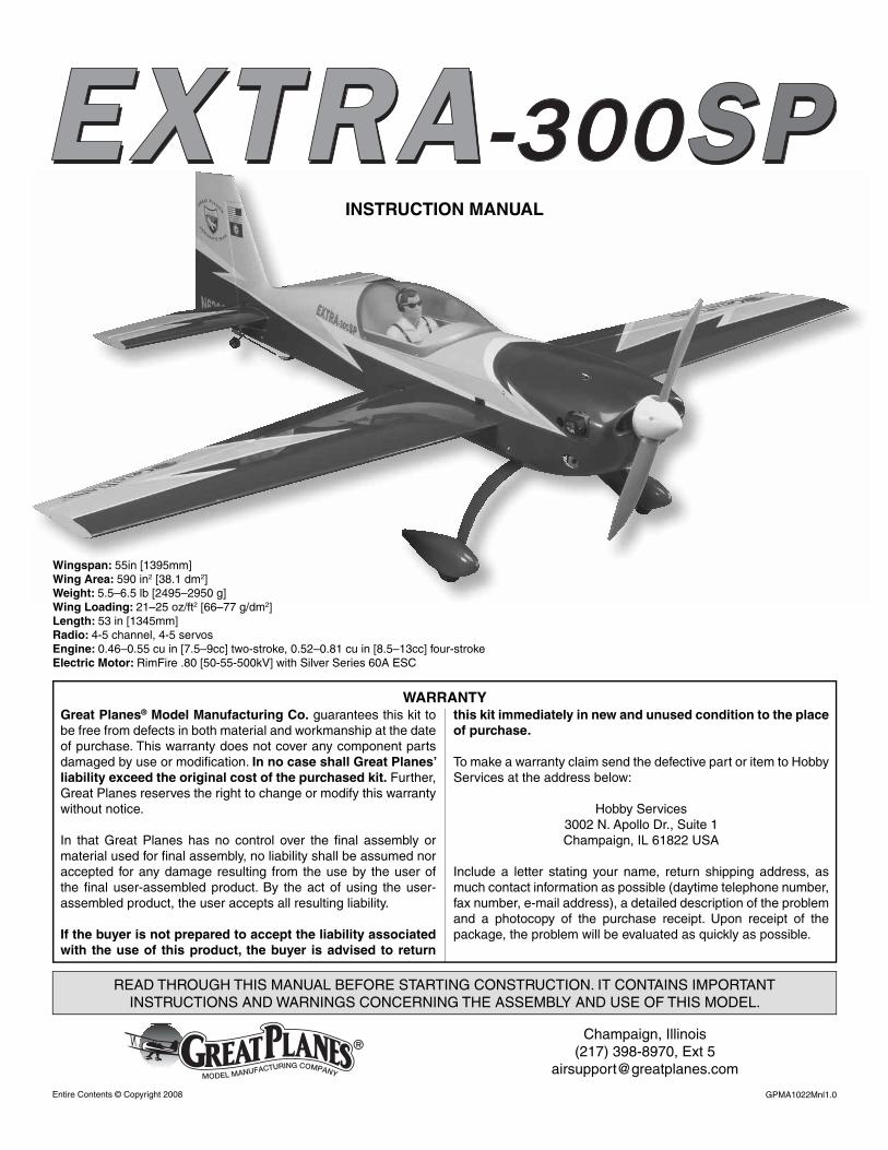
Wingspan: 55in [1395mm] Wing Area: 590 in2 [38.1 dm2] Weight: 5.5–6.5 lb [2495–2950 g]Wing Loading: 21–25 oz/ft2 [66–77 g/dm2] Length: 53 in [1345mm] Radio: 4-5 channel, 4-5 servosEngine: 0.46–0.55 cu in [7.5–9cc] two-stroke, 0.52–0.81 cu in [8.5–13cc] four-strokeElectric Motor: RimFire .80 [50-55-500kV] with Silver Series 60A ESC
2
TABLE OF CONTENTS
INTRODUCTION ............................................................... 2AMA .................................................................................. 2ELECTRIC MOTOR AND SAFETY PRECAUTIONS ....... 3DECISIONS YOU MUST MAKE ........................................ 3 Glow Engine Accessories .......................................... 3 Electric Motor Accessories......................................... 4 Radio Equipment ....................................................... 4 Additional Radio Accessories .................................... 4ADDITIONAL ITEMS REQUIRED .................................... 5 Required Hardware and Accessories ........................ 5 Adhesives and Building Supplies ............................... 5 Covering Tools ........................................................... 5 Optional Supplies and Tools ....................................... 5IMPORTANT BUILDING NOTES ...................................... 5ORDERING REPLACEMENT PARTS .............................. 6KIT INSPECTION .............................................................. 7KIT CONTENTS ................................................................ 7SHRINK THE COVERING ................................................. 8BUILD THE WINGS ........................................................... 8 Hinge the Ailerons ...................................................... 8 Install the Wing Dowels .............................................. 9 Install the Aileron Servos ........................................... 9ASSEMBLE THE FUSELAGE ........................................ 11 Attach the Horizontal Stabilizer ................................ 11 Hinge the Rudder and Elevators .............................. 13 Landing Gear Installation ......................................... 14 Install the Elevator Servo ......................................... 14 Install the Hatch ....................................................... 15 Install the Electric Motor and Rudder Servo ............ 16 Install the Glow Engine and Rudder Servo .............. 19 Install the Fuel Tank ................................................. 20 Install the Radio Gear and Cowl .............................. 21 Mount the Prop and Spinner .................................... 22 Apply the Decals ...................................................... 22GET THE MODEL READY TO FLY ................................. 22 Install and Connect the Motor Battery ..................... 22 Check the Control Directions ................................... 23 Set the Control Throws ............................................ 24 Balance Model (C.G.)............................................... 24 Balance the Model Laterally ..................................... 25PREFLIGHT .................................................................... 25 Identify Your Model ................................................... 25 Charge the Batteries ................................................ 25 Balance Propellers ................................................... 25 Ground Check .......................................................... 25 Range Check ........................................................... 26ENGINE SAFETY PRECAUTIONS ................................. 26AMA SAFETY CODE ...................................................... 26CHECKLIST .................................................................... 27FLYING ............................................................................ 27 Mount the Wing ........................................................ 27 Fuel Mixture Adjustments ........................................ 27 Takeoff .......................................................Back Cover Flight ..........................................................Back Cover Landing ......................................................Back Cover
INTRODUCTION
Thank you for purchasing the Great Planes Extra 300SP .46 ARF. This model has been designed to excel in all aspects of RC aerobatic fl ight. Great lengths have been taken to ensure the Great Planes Extra 300SP .46 ARF is able to fulfi ll the demands of the most critical modeler. Whether you desire to use glow or electric power, design features are in place to enhance the attributes of both power systems. Two rudder placement locations and alternate battery mounting positions have been included to eliminate the need for lead ballast. This model is capable of the most extreme 3D aerobatic maneuvers, pinpoint precision, and relaxing Sunday fl ying. Whatever your fl ying preference, the Great Planes Extra 300SP .46 ARF is certain to make a great addition to your hangar.
For the latest technical updates or manual corrections to the Great Planes Extra 300SP .46 ARF visit the Great Planes web site at www.greatplanes.com. Open the “R/C AIRPLANES” pull down tab across the top of the page, and then select “ARFs-GLOW.” Scroll down the page and click on “Extra 300SP .46 ARF”. If there is new technical information or changes to this model an “Important! TECH NOTICE” box will appear in the upper left corner of the page. Click on the Tech Notice box to read the information.
AMA
We urge you to join the AMA (Academy of Model Aeronautics) and a local R/C club. The AMA is the governing body of model aviation and membership is required to fl y at AMA clubs. Though joining the AMA provides many benefi ts, one of the primary reasons to join is liability protection. Coverage is not limited to fl ying at contests or on the club fi eld. It even applies to fl ying at public demonstrations and air shows. Failure to comply with the Safety Code (excerpts printed in the back of the manual) may endanger insurance coverage. Additionally, training programs and instructors are available at AMA club sites to help you get started the right way. There are over 2,500 AMA chartered clubs across the country. Contact the AMA at the address or toll-free phone number shown.
Academy of Model Aeronautics5151 East Memorial Drive
Muncie, IN 47302Tele: (800) 435-9262Fax (765) 741-0057
Or via the Internet at:www.modelaircraft.org
IMPORTANT!!! Two of the most important things you can do to preserve the radio controlled aircraft hobby are to avoid fl ying near full-scale aircraft and avoid fl ying near or over groups of people.
3
PROTECT YOUR MODEL, YOURSELF & OTHERS...FOLLOW THESE
IMPORTANT SAFETY PRECAUTIONS
1. Your Great Planes Extra 300SP .46 ARF should not be considered a toy, but rather a sophisticated, working model that functions very much like a full-size airplane. Because of its performance capabilities, the Great Planes Extra 300SP .46 ARF, if not assembled and operated correctly, could possibly cause injury to yourself or spectators and damage to property.
2. You must assemble the model according to the instructions. Do not alter or modify the model, as doing so may result in an unsafe or unfl yable model. In a few cases the instructions may differ slightly from the photos. In those instances the written instructions should be considered as correct.
3. You must take time to build straight, true and strong.
4. You must use an R/C radio system that is in fi rst-class condition and a correctly sized engine and components (fuel tank, wheels, etc.) throughout the building process.
5. You must correctly install all R/C and other components so that the model operates correctly on the ground and in the air.
6. You must check the operation of the model before every fl ight to ensure that all equipment is operating and that the model has remained structurally sound. Be sure to check clevises or other connectors often and replace them if they show any signs of wear or fatigue.
7. If you are not an experienced pilot or have not fl own this type of model before, we recommend that you get the assistance of an experienced pilot in your R/C club for your fi rst fl ights. If you’re not a member of a club, your local hobby shop has information about clubs in your area whose membership includes experienced pilots.
8. While this kit has been fl ight tested to exceed normal use, if the plane will be used for extremely high stress fl ying, such as racing, or if an engine larger than one in the recommended range is used, the modeler is responsible for taking steps to reinforce the high stress points and/or substituting hardware more suitable for the increased stress.
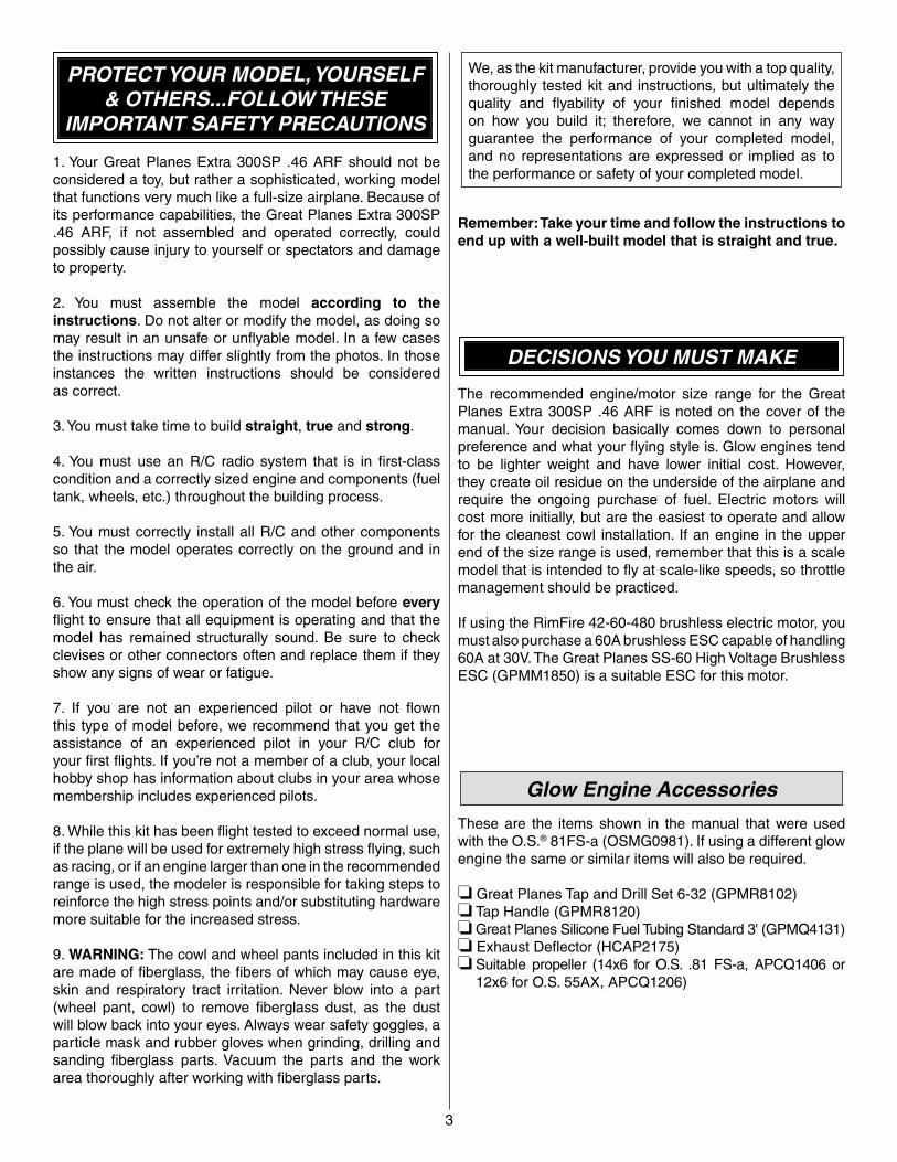
9. WARNING: The cowl and wheel pants included in this kit are made of fi berglass, the fi bers of which may cause eye, skin and respiratory tract irritation. Never blow into a part (wheel pant, cowl) to remove fi berglass dust, as the dust will blow back into your eyes. Always wear safety goggles, a particle mask and rubber gloves when grinding, drilling and sanding fi berglass parts. Vacuum the parts and the work area thoroughly after working with fi berglass parts.
We, as the kit manufacturer, provide you with a top quality, thoroughly tested kit and instructions, but ultimately the quality and fl yability of your fi nished model depends on how you build it; therefore, we cannot in any way guarantee the performance of your completed model, and no representations are expressed or implied as to the performance or safety of your completed model.
Remember: Take your time and follow the instructions to end up with a well-built model that is straight and true.
DECISIONS YOU MUST MAKE
The recommended engine/motor size range for the Great Planes Extra 300SP .46 ARF is noted on the cover of the manual. Your decision basically comes down to personal preference and what your fl ying style is. Glow engines tend to be lighter weight and have lower initial cost. However, they create oil residue on the underside of the airplane and require the ongoing purchase of fuel. Electric motors will cost more initially, but are the easiest to operate and allow for the cleanest cowl installation. If an engine in the upper end of the size range is used, remember that this is a scale model that is intended to fl y at scale-like speeds, so throttle management should be practiced.
If using the RimFire 42-60-480 brushless electric motor, you must also purchase a 60A brushless ESC capable of handling 60A at 30V. The Great Planes SS-60 High Voltage Brushless ESC (GPMM1850) is a suitable ESC for this motor.
Glow Engine Accessories
These are the items shown in the manual that were used with the O.S.® 81FS-a (OSMG0981). If using a different glow engine the same or similar items will also be required.
❏ Great Planes Tap and Drill Set 6-32 (GPMR8102)❏ Tap Handle (GPMR8120)❏ Great Planes Silicone Fuel Tubing Standard 3' (GPMQ4131)❏ Exhaust Defl ector (HCAP2175)❏ Suitable propeller (14x6 for O.S. .81 FS-a, APCQ1406 or
12x6 for O.S. 55AX, APCQ1206)
Electric Motor Accessories
These are the items shown in the manual that were used with the RimFire .80 [50-55-500kV] (GPMG4740).
❏ Great Planes Large Electric Motor Mount (GPMG1260)❏ Silver Series 60A ESC (GPMM1850)❏ Silver Series ESC Programming Card (GPMM1895)❏ Suitable propeller such as 15x7E (APCQ1830)❏ Velcro hook & loop adhesive strips (1"x6" [25x150mm]
GPMQ4480)
There may be many different battery and propeller combinations available that will work well with the recommended brushless RimFire motor for this model. However, the following setup is one that has been tested with the Great Planes Extra 300SP .46 ARF and has proven to have the best overall performance.
❏ Two ElectriFly™ 3200mAh 11.1V LiPo battery packs (GPMP0623) These batteries will be connected in series. This is what is refered to as a “6S” confi guration, because it is comprised of two 11.1V LiPo battery packs, each consisting of three individual 3.7V LiPo cells connected in series.
❏ Great Planes ElectriFly Series Deans® U 2 to 1 battery adapter (GPMM3143)
IMPORTANT: Before experimenting with different battery combinations and connecting multiple battery packs with adapter plugs, refer to the Battery Precautions on page 22.
If using LiPo batteries, a charger specially suited for charging LiPo batteries is required. The Great Planes PolyCharge™ 4(GPMM3015) is recommended for charging the batteries recommended. The PolyCharge 4 will charge up to four LiPo batteries simultaneously. If using the PolyCharge 4, a 12 volt source will also be required for powering the charger. If you plan on charging four 3,200mAh batteries simultaneously, a power source capable of delivering at least 12.8A is required. A suitable 12V auto battery could be used, or a portable source capable of converting 120V AC to 12V DC such as the Rivergate 15A DC Bulldog Power Supply (RHCP2015) is suitable. If charging only three 3,200 batteries simultaneously, the Hobbico® 12 Volt Power Supply (HCAP0250) is also suitable.
When charging LiPo batteries, it is recommended that you use a balancer. A balancer will extend the life of the batteries as well as reduce the risk of damaging the batteries during charging. A suitable balancer for the Great Planes ElectriFly Power Series™ LiPo batteries is the Great Planes ElectriFly Equinox™ LiPo Cell Balancer (GPMM3160)
If not using a balancer, one charge adapter connector per battery is also required. For the batteries and charger recommended, the Great Planes Banana Plugs to Deans Male Ultra Plug® battery charging connectors can be used (GPMM3148).
Radio Equipment
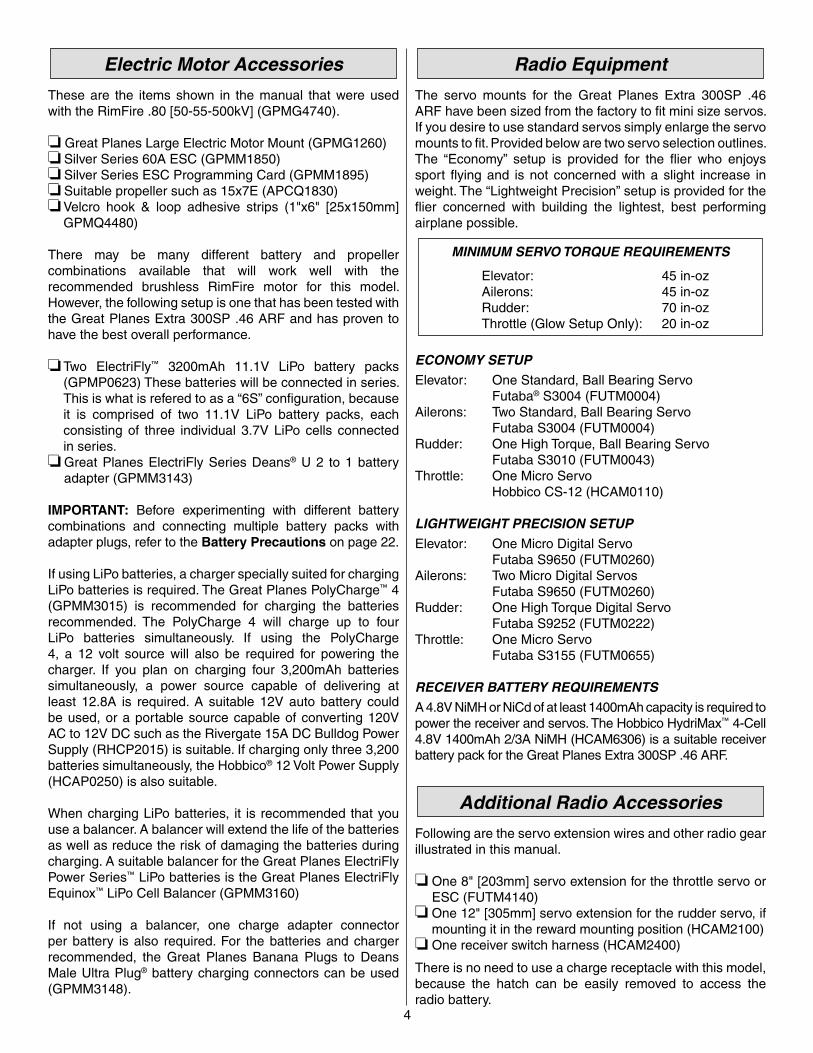
The servo mounts for the Great Planes Extra 300SP .46 ARF have been sized from the factory to fi t mini size servos. If you desire to use standard servos simply enlarge the servo mounts to fi t. Provided below are two servo selection outlines. The “Economy” setup is provided for the fl ier who enjoys sport fl ying and is not concerned with a slight increase in weight. The “Lightweight Precision” setup is provided for the fl ier concerned with building the lightest, best performing airplane possible.
MINIMUM SERVO TORQUE REQUIREMENTS
Elevator: 45 in-oz Ailerons: 45 in-oz Rudder: 70 in-oz Throttle (Glow Setup Only): 20 in-oz
ECONOMY SETUP
Elevator: One Standard, Ball Bearing ServoFutaba® S3004 (FUTM0004)
Ailerons: Two Standard, Ball Bearing Servo Futaba S3004 (FUTM0004)
Rudder: One High Torque, Ball Bearing ServoFutaba S3010 (FUTM0043)
Throttle: One Micro ServoHobbico CS-12 (HCAM0110)
LIGHTWEIGHT PRECISION SETUP
Elevator: One Micro Digital ServoFutaba S9650 (FUTM0260)
Ailerons: Two Micro Digital ServosFutaba S9650 (FUTM0260)
Rudder: One High Torque Digital ServoFutaba S9252 (FUTM0222)
Throttle: One Micro ServoFutaba S3155 (FUTM0655)
RECEIVER BATTERY REQUIREMENTS
A 4.8V NiMH or NiCd of at least 1400mAh capacity is required to power the receiver and servos. The Hobbico HydriMax™ 4-Cell 4.8V 1400mAh 2/3A NiMH (HCAM6306) is a suitable receiver battery pack for the Great Planes Extra 300SP .46 ARF.
Additional Radio Accessories
Following are the servo extension wires and other radio gear illustrated in this manual.
❏ One 8" [203mm] servo extension for the throttle servo or ESC (FUTM4140)
❏ One 12" [305mm] servo extension for the rudder servo, if mounting it in the reward mounting position (HCAM2100)
❏ One receiver switch harness (HCAM2400)
There is no need to use a charge receptacle with this model, because the hatch can be easily removed to access the radio battery.
4
5
ADDITIONAL ITEMS REQUIRED
In addition to the items previously mentioned in the “Decisions You Must Make” section, the following is a list of hardware and accessories required to fi nish the Extra 300SP .46 ARF. Part numbers are provided in parentheses.
Required Hardware and Accessories
❏ Suitable propeller and spare propellers❏ R/C foam rubber (1/4" [6mm] – HCAQ1000, or 1/2" [13mm]
– HCAQ1050)❏ Dubro Servo Arms Super Strength, Futaba J, Long
(DUBM6670, if setting up for 3D throws)
Adhesives and Building Supplies
Here is a list of Adhesives and Building Supplies that are required to fi nish the Extra 300SP ARF.
❏ Great Planes Pro™ CA Glue Thin (GPMR6002)❏ Great Planes Pro CA Glue Thick (GPMR6014)❏ Great Planes Pro Epoxy 6-Minute (GPMR6042)❏ Great Planes Pro Epoxy 30-Minute (GPMR6043)❏ Denatured Alcohol❏ Great Planes Pro Threadlocker (GPMR6060)❏ Micro Bearing Oiler (TRIC8025)❏ Hobby Knife with #11 blades (HCAR0101)❏ Hobbico Steel T-pins 1-1/4" (HCAR5150)❏ Marker❏ Drill Bits: 1/16" [1.6mm], 5/64" [2mm], 5/32" [4mm],
3/8" [9.6mm]
Covering Tools
A Top Flite® or Coverite 21ST Century® model airplane covering iron with a protective covering sock will be necessary for tightening any covering on the model that may have loosened or formed wrinkles between the time of production and your purchase. The Coverite 21ST Century iron is preferred as it has a longer cord and a rounded, contoured shoe. A trim iron is not as much of a necessity, but would still be very handy for sealing the edges down inside servo openings and other small areas.
❏ Coverite 21st Century sealing iron (COVR2700) ❏ Coverite 21st Century iron cover (COVR2702)❏ Coverite 21st Century trim seal iron (COVR2750)
or
❏ Top Flite MonoKote® sealing iron (TOPR2100) ❏ Top Flite Hot Sock™ iron cover (TOPR2175)❏ Top Flite MonoKote trim seal iron (TOPR2200)
Optional Supplies and Tools
Here is a list of optional tools mentioned in the manual that will help when assembling the Extra 300SP .46 ARF.
❏ Long Nose Pliers (HCAR0625)❏ Diagonal Pliers (HCAR0627)❏ Phillips Head Screwdriver #1 (DTXR0174)❏ Hobbico Flexible 18" Ruler Stainless Steel (HCAR0460)❏ 3/8" Heat Shrink Tubing (GPMM1060)❏ Great Planes 4-in-1 Installation Tool (GPMR8035)❏ Hobbico Builder’s Triangle Set (HCAR0480)❏ Hobbico Flexible 18" Ruler (HCAR0460)❏ Hobbico Retractable Fabric Tape Measure (HCAR0478)❏ Robart Build Stand (ROBP1402)❏ Rotary Tool (DRER0550)❏ Standard Hex Wrenches (BONR1530)❏ Metric Hex Wrenches (BONR1510)❏ Hemostats (BRUR1302)❏ Stick-on Segmented Lead Weights (GPMQ4485)❏ 2 oz. [57g] Spray CA Activator (GPMR6035)❏ 4 oz. [113g] Aerosol CA Activator (GPMR6034)❏ Precision Magnetic Prop Balancer (TOPQ5700)❏ CA Debonder (GPMR6039)❏ Epoxy Brushes (GPMR8060)❏ Mixing Sticks (GPMR8055)❏ Mixing Cups (GPMR8056)❏ Denatured Alcohol
IMPORTANT BUILDING NOTES
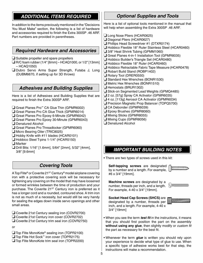
• There are two types of screws used in this kit:
Self-tapping screws are designated by a number and a length. For example, #6 x 3/4" [19mm].
Machine screws are designated by a number, threads per inch, and a length. For example, 4-40 x 3/4" [19mm].
Socket Head Cap Screws (SHCS) are designated by a number, threads per inch, and a length. For example, 4-40 x 3/4" [19mm]
• When you see the term test fi t in the instructions, it means that you should fi rst position the part on the assembly without using any glue, then slightly modify or custom fi t the part as necessary for the best fi t.
• Whenever the term glue is written you should rely upon your experience to decide what type of glue to use. When a specifi c type of adhesive works best for that step, the instructions will make a recommendation.
6
• Whenever just epoxy is specifi ed you may use either 30-minute (or 45-minute) epoxy or 6-minute epoxy. When 30-minute epoxy is specifi ed it is highly recommended that you use only 30-minute (or 45-minute) epoxy, because you will need the working time and/or the additional strength.
• Photos and sketches are placed before the step they refer to. Frequently you can study photos in following steps to get another view of the same parts.
• The Great Planes Extra 300SP .46 ARF is factory-covered with Top Flite MonoKote fi lm. Should repairs ever be required, MonoKote can be patched with additional MonoKote purchased separately. MonoKote is packaged in six-foot rolls, but some hobby shops also sell it by the foot. If only a small piece of MonoKote is needed for a minor patch, perhaps a fellow modeler would give you some. MonoKote is applied with a model airplane covering iron, but in an emergency a regular iron could be used. A roll of MonoKote includes full instructions for application. Following are the colors used on this model and order numbers for six foot rolls.
Yellow (TOPQ0203) Jet White (TOPQ0204) Metallic Blue (TOPQ0402) Metallic Platinum (TOPQ0408)
• The stabilizer and wing incidences and engine thrust angles have been factory-built into this model. However, some technically-minded modelers may wish to check these measurements anyway. To view this information visit the web site at www.greatplanes.com and click on “Technical Data.” Due to manufacturing tolerances which will have little or no effect on the way your model will fl y, please expect slight deviations between your model and the published values.
ORDERING REPLACEMENT PARTS
Replacement parts for the Extra 300SP .46 ARF are available using the order numbers in the Replacement Parts List that follows. The fastest, most economical service can be provided by your hobby dealer or mail-order company.
To locate a hobby dealer, visit the Great Planes web site at www.greatplanes.com. Choose “Where to Buy” at the bottom of the menu on the left side of the page. Follow the instructions provided on the page to locate a U.S., Canadian or International dealer.
Parts may also be ordered directly from Hobby Services by calling (217) 398-0007, or via facsimile at (217) 398-7721, but full retail prices and shipping and handling charges will apply. Illinois and Nevada residents will also be charged sales tax. If ordering via fax, include a Visa® or MasterCard® number and expiration date for payment.
Mail parts orders and payments by personal check to:
Hobby Services3002 N. Apollo Drive, Suite 1
Champaign, IL 61822
Be certain to specify the order number exactly as listed in the Replacement Parts List. Payment by credit card or personal check only; no C.O.D.
If additional assistance is required for any reason, contact Product Support by telephone at (217) 398-8970, or by e-mail at [email protected].
REPLACEMENT PARTS LIST Order Number Description How to Purchase Missing pieces ....Contact Product Support Instruction manual Contact Product Support Full-size plans ........................Not available
Contact your hobby supplier for the following parts:
GPMA3217 ...... Wing SetGPMA3218 ...... Fuselage w/Canopy HatchGPMA3219 ...... Tail Surface SetGPMA3220 ...... Wing Joiner TubeGPMA3221 ...... CowlGPMA3222 ...... CanopyGPMA3223 ...... Landing GearGPMA3224 ...... Wheel Pants Set Left/RightGPMA3225 ...... Decal Sheet
7
KIT INSPECTION
Before starting to build inspect the parts to make sure they are of acceptable quality. If any parts are missing or are not of acceptable quality, or if you need assistance with assembly, contact Product Support. When reporting defective or missing parts, use the part names exactly as they are written in the Kit Contents list.
Great Planes Product Support3002 N. Apollo Drive, Suite 1
Champaign, IL 61822Telephone: (217) 398-8970, ext. 5
Fax: (217) 398-7721E-mail: [email protected]
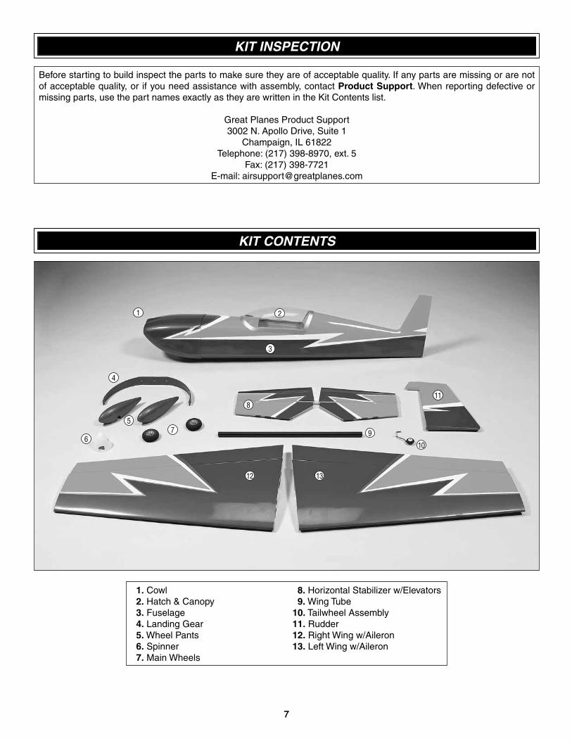
KIT CONTENTS
1. Cowl 2. Hatch & Canopy 3. Fuselage 4. Landing Gear 5. Wheel Pants 6. Spinner 7. Main Wheels
8. Horizontal Stabilizer w/Elevators 9. Wing Tube 10. Tailwheel Assembly 11. Rudder 12. Right Wing w/Aileron 13. Left Wing w/Aileron
1
6
2
11
12 13
5
4
10
9
8
7
3
7
888
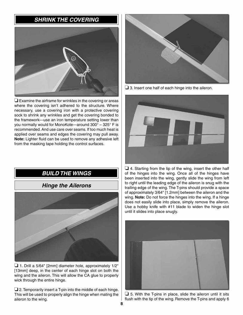
SHRINK THE COVERING
❏ Examine the airframe for wrinkles in the covering or areas where the covering isn’t adhered to the structure. Where necessary, use a covering iron with a protective covering sock to shrink any wrinkles and get the covering bonded to the framework—use an iron temperature setting lower than you normally would for MonoKote—around 300° – 325° F is recommended. And use care over seams. If too much heat is applied over seams and edges the covering may pull away. Note: Lighter fl uid can be used to remove any adhesive left from the masking tape holding the control surfaces.
BUILD THE WINGS
Hinge the Ailerons
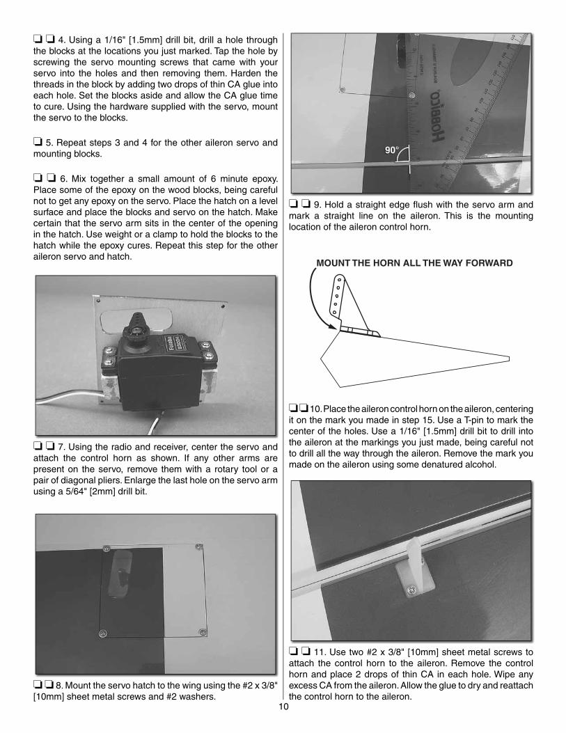
❏ 1. Drill a 5/64" [2mm] diameter hole, approximately 1/2" [13mm] deep, in the center of each hinge slot on both the wing and the aileron. This will allow the CA glue to properly wick through the entire hinge.
❏ 2. Temporarily insert a T-pin into the middle of each hinge. This will be used to properly align the hinge when mating the aileron to the wing.
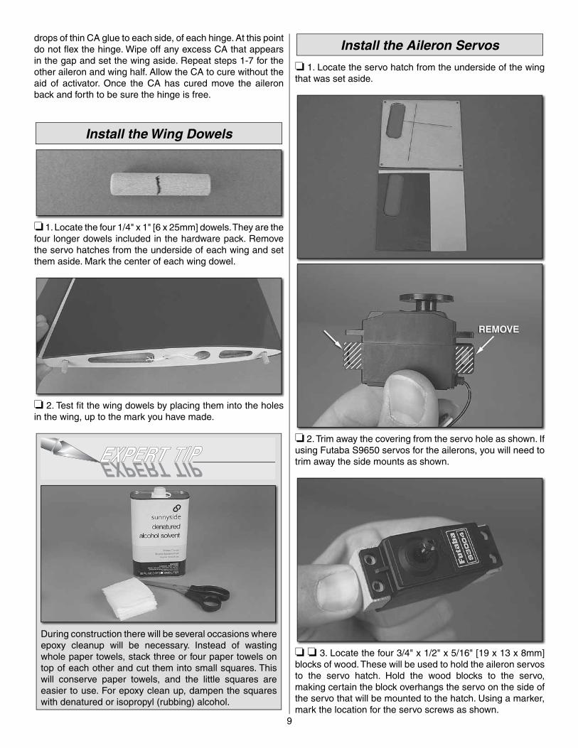
❏ 3. Insert one half of each hinge into the aileron.
❏ 4. Starting from the tip of the wing, insert the other half of the hinges into the wing. Once all of the hinges have been inserted into the wing, gently slide the wing from left to right until the leading edge of the aileron is snug with the trailing edge of the wing. The T-pins should provide a space of approximately 3/64" [1.2mm] between the aileron and the wing. Note: Do not force the hinges into the wing. If a hinge does not easily slide into place, simply remove the aileron. Use a hobby knife with #11 blade to widen the hinge slot until it slides into place snugly.
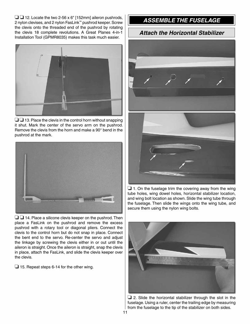
❏ 5. With the T-pins in place, slide the aileron until it sits fl ush with the tip of the wing. Remove the T-pins and apply 6
9
drops of thin CA glue to each side, of each hinge. At this point do not fl ex the hinge. Wipe off any excess CA that appears in the gap and set the wing aside. Repeat steps 1-7 for the other aileron and wing half. Allow the CA to cure without the aid of activator. Once the CA has cured move the aileron back and forth to be sure the hinge is free.
Install the Wing Dowels
❏ 1. Locate the four 1/4" x 1" [6 x 25mm] dowels. They are the four longer dowels included in the hardware pack. Remove the servo hatches from the underside of each wing and set them aside. Mark the center of each wing dowel.
❏ 2. Test fi t the wing dowels by placing them into the holes in the wing, up to the mark you have made.
During construction there will be several occasions where epoxy cleanup will be necessary. Instead of wasting whole paper towels, stack three or four paper towels on top of each other and cut them into small squares. This will conserve paper towels, and the little squares are easier to use. For epoxy clean up, dampen the squares with denatured or isopropyl (rubbing) alcohol.
Install the Aileron Servos
❏ 1. Locate the servo hatch from the underside of the wing that was set aside.
❏ 2. Trim away the covering from the servo hole as shown. If using Futaba S9650 servos for the ailerons, you will need to trim away the side mounts as shown.
❏ ❏ 3. Locate the four 3/4" x 1/2" x 5/16" [19 x 13 x 8mm] blocks of wood. These will be used to hold the aileron servos to the servo hatch. Hold the wood blocks to the servo, making certain the block overhangs the servo on the side of the servo that will be mounted to the hatch. Using a marker, mark the location for the servo screws as shown.
10
❏ ❏ 4. Using a 1/16" [1.5mm] drill bit, drill a hole through the blocks at the locations you just marked. Tap the hole by screwing the servo mounting screws that came with your servo into the holes and then removing them. Harden the threads in the block by adding two drops of thin CA glue into each hole. Set the blocks aside and allow the CA glue time to cure. Using the hardware supplied with the servo, mount the servo to the blocks.
❏ 5. Repeat steps 3 and 4 for the other aileron servo and mounting blocks.
❏ ❏ 6. Mix together a small amount of 6 minute epoxy. Place some of the epoxy on the wood blocks, being careful not to get any epoxy on the servo. Place the hatch on a level surface and place the blocks and servo on the hatch. Make certain that the servo arm sits in the center of the opening in the hatch. Use weight or a clamp to hold the blocks to the hatch while the epoxy cures. Repeat this step for the other aileron servo and hatch.
❏ ❏ 7. Using the radio and receiver, center the servo and attach the control horn as shown. If any other arms are present on the servo, remove them with a rotary tool or a pair of diagonal pliers. Enlarge the last hole on the servo arm using a 5/64" [2mm] drill bit.
❏ ❏ 8. Mount the servo hatch to the wing using the #2 x 3/8" [10mm] sheet metal screws and #2 washers.
❏ ❏ 9. Hold a straight edge fl ush with the servo arm and mark a straight line on the aileron. This is the mounting location of the aileron control horn.
MOUNT THE HORN ALL THE WAY FORWARD
❏ ❏ 10. Place the aileron control horn on the aileron, centering it on the mark you made in step 15. Use a T-pin to mark the center of the holes. Use a 1/16" [1.5mm] drill bit to drill into the aileron at the markings you just made, being careful not to drill all the way through the aileron. Remove the mark you made on the aileron using some denatured alcohol.
❏ ❏ 11. Use two #2 x 3/8" [10mm] sheet metal screws to attach the control horn to the aileron. Remove the control horn and place 2 drops of thin CA in each hole. Wipe any excess CA from the aileron. Allow the glue to dry and reattach the control horn to the aileron.
11
❏ ❏ 12. Locate the two 2-56 x 6" [152mm] aileron pushrods, 2 nylon clevises, and 2 nylon FasLink™ pushrod keeper. Screw the clevis onto the threaded end of the pushrod by rotating the clevis 18 complete revolutions. A Great Planes 4-in-1 Installation Tool (GPMR8035) makes this task much easier.
❏ ❏ 13. Place the clevis in the control horn without snapping it shut. Mark the center of the servo arm on the pushrod. Remove the clevis from the horn and make a 90° bend in the pushrod at the mark.
❏ ❏ 14. Place a silicone clevis keeper on the pushrod. Then place a FasLink on the pushrod and remove the excess pushrod with a rotary tool or diagonal pliers. Connect the clevis to the control horn but do not snap in place. Connect the bent end to the servo. Re-center the servo and adjust the linkage by screwing the clevis either in or out until the aileron is straight. Once the aileron is straight, snap the clevis in place, attach the FasLink, and slide the clevis keeper over the clevis.
❏ 15. Repeat steps 6-14 for the other wing.
ASSEMBLE THE FUSELAGE
Attach the Horizontal Stabilizer
❏ 1. On the fuselage trim the covering away from the wing tube holes, wing dowel holes, horizontal stabilizer location, and wing bolt location as shown. Slide the wing tube through the fuselage. Then slide the wings onto the wing tube, and secure them using the nylon wing bolts.
❏ 2. Slide the horizontal stabilizer through the slot in the fuselage. Using a ruler, center the trailing edge by measuring from the fuselage to the tip of the stabilizer on both sides.
12
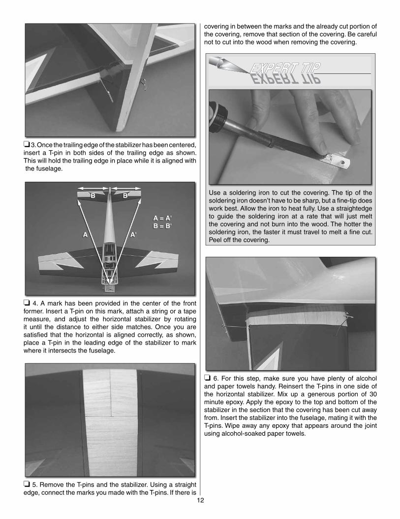
❏ 3. Once the trailing edge of the stabilizer has been centered, insert a T-pin in both sides of the trailing edge as shown. This will hold the trailing edge in place while it is aligned with the fuselage.
❏ 4. A mark has been provided in the center of the front former. Insert a T-pin on this mark, attach a string or a tape measure, and adjust the horizontal stabilizer by rotating it until the distance to either side matches. Once you are satisfi ed that the horizontal is aligned correctly, as shown, place a T-pin in the leading edge of the stabilizer to mark where it intersects the fuselage.
❏ 5. Remove the T-pins and the stabilizer. Using a straight edge, connect the marks you made with the T-pins. If there is
covering in between the marks and the already cut portion of the covering, remove that section of the covering. Be careful not to cut into the wood when removing the covering.
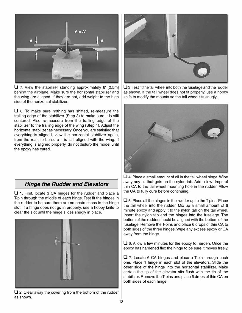
Use a soldering iron to cut the covering. The tip of the soldering iron doesn’t have to be sharp, but a fine-tip does work best. Allow the iron to heat fully. Use a straightedge to guide the soldering iron at a rate that will just melt the covering and not burn into the wood. The hotter the soldering iron, the faster it must travel to melt a fine cut. Peel off the covering.
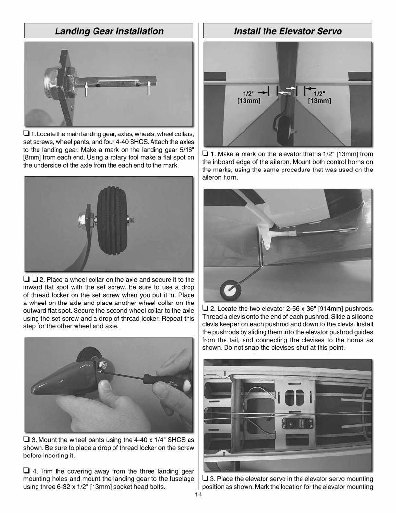
❏ 6. For this step, make sure you have plenty of alcohol and paper towels handy. Reinsert the T-pins in one side of the horizontal stabilizer. Mix up a generous portion of 30 minute epoxy. Apply the epoxy to the top and bottom of the stabilizer in the section that the covering has been cut away from. Insert the stabilizer into the fuselage, mating it with the T-pins. Wipe away any epoxy that appears around the joint using alcohol-soaked paper towels.
13
❏ 7. View the stabilizer standing approximately 6' [2.5m] behind the airplane. Make sure the horizontal stabilizer and the wing are aligned. If they are not, add weight to the high side of the horizontal stabilizer.
❏ 8. To make sure nothing has shifted, re-measure the trailing edge of the stabilizer (Step 3) to make sure it is still centered. Also re-measure from the trailing edge of the stabilizer to the trailing edge of the wing (Step 4). Adjust the horizontal stabilizer as necessary. Once you are satisfi ed that everything is aligned, view the horizontal stabilizer again, from the rear, to be sure it is still aligned with the wing. If everything is aligned properly, do not disturb the model until the epoxy has cured.
Hinge the Rudder and Elevators
❏ 1. First, locate 3 CA hinges for the rudder and place a T-pin through the middle of each hinge. Test fi t the hinges in the rudder to be sure there are no obstructions in the hinge slot. If a hinge does not go in properly, use a hobby knife to clear the slot until the hinge slides snugly in place.
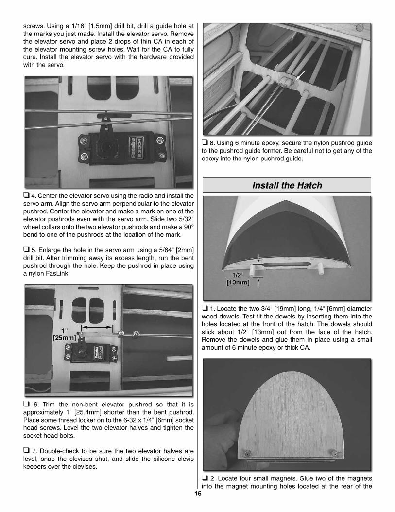
❏ 2. Clear away the covering from the bottom of the rudder as shown.
❏ 3. Test fi t the tail wheel into both the fuselage and the rudder as shown. If the tail wheel does not fi t properly, use a hobby knife to modify the mounts so the tail wheel fi ts snugly.
❏ 4. Place a small amount of oil in the tail wheel hinge. Wipe away any oil that gets on the nylon tab. Add a few drops of thin CA to the tail wheel mounting hole in the rudder. Allow the CA to fully cure before continuing.
❏ 5. Place all the hinges in the rudder up to the T-pins. Place the tail wheel into the rudder. Mix up a small amount of 6 minute epoxy and apply it to the nylon tab on the tail wheel. Insert the nylon tab and the hinges into the fuselage. The bottom of the rudder should be aligned with the bottom of the fuselage. Remove the T-pins and place 6 drops of thin CA to both sides of the three hinges. Wipe any excess epoxy or CA away from the hinge.
❏ 6. Allow a few minutes for the epoxy to harden. Once the epoxy has hardened fl ex the hinge to be sure it moves freely.
❏ 7. Locate 6 CA hinges and place a T-pin through each one. Place 1 hinge in each slot of the elevators. Slide the other side of the hinge into the horizontal stabilizer. Make certain the tip of the elevator sits fl ush with the tip of the stabilizer. Remove the T-pins and place 6 drops of thin CA on both sides of each hinge.
14
Landing Gear Installation
❏ 1. Locate the main landing gear, axles, wheels, wheel collars, set screws, wheel pants, and four 4-40 SHCS. Attach the axles to the landing gear. Make a mark on the landing gear 5/16" [8mm] from each end. Using a rotary tool make a fl at spot on the underside of the axle from the each end to the mark.
❏ ❏ 2. Place a wheel collar on the axle and secure it to the inward fl at spot with the set screw. Be sure to use a drop of thread locker on the set screw when you put it in. Place a wheel on the axle and place another wheel collar on the outward fl at spot. Secure the second wheel collar to the axle using the set screw and a drop of thread locker. Repeat this step for the other wheel and axle.
❏ 3. Mount the wheel pants using the 4-40 x 1/4" SHCS as shown. Be sure to place a drop of thread locker on the screw before inserting it.
❏ 4. Trim the covering away from the three landing gear mounting holes and mount the landing gear to the fuselage using three 6-32 x 1/2" [13mm] socket head bolts.
Install the Elevator Servo
❏ 1. Make a mark on the elevator that is 1/2" [13mm] from the inboard edge of the aileron. Mount both control horns on the marks, using the same procedure that was used on the aileron horn.
❏ 2. Locate the two elevator 2-56 x 36" [914mm] pushrods. Thread a clevis onto the end of each pushrod. Slide a silicone clevis keeper on each pushrod and down to the clevis. Install the pushrods by sliding them into the elevator pushrod guides from the tail, and connecting the clevises to the horns as shown. Do not snap the clevises shut at this point.
❏ 3. Place the elevator servo in the elevator servo mounting position as shown. Mark the location for the elevator mounting
15
screws. Using a 1/16" [1.5mm] drill bit, drill a guide hole at the marks you just made. Install the elevator servo. Remove the elevator servo and place 2 drops of thin CA in each of the elevator mounting screw holes. Wait for the CA to fully cure. Install the elevator servo with the hardware provided with the servo.
❏ 4. Center the elevator servo using the radio and install the servo arm. Align the servo arm perpendicular to the elevator pushrod. Center the elevator and make a mark on one of the elevator pushrods even with the servo arm. Slide two 5/32" wheel collars onto the two elevator pushrods and make a 90° bend to one of the pushrods at the location of the mark.
❏ 5. Enlarge the hole in the servo arm using a 5/64" [2mm] drill bit. After trimming away its excess length, run the bent pushrod through the hole. Keep the pushrod in place using a nylon FasLink.
❏ 6. Trim the non-bent elevator pushrod so that it is approximately 1" [25.4mm] shorter than the bent pushrod. Place some thread locker on to the 6-32 x 1/4" [6mm] socket head screws. Level the two elevator halves and tighten the socket head bolts.
❏ 7. Double-check to be sure the two elevator halves are level, snap the clevises shut, and slide the silicone clevis keepers over the clevises.
❏ 8. Using 6 minute epoxy, secure the nylon pushrod guide to the pushrod guide former. Be careful not to get any of the epoxy into the nylon pushrod guide.
Install the Hatch
❏ 1. Locate the two 3/4" [19mm] long, 1/4" [6mm] diameter wood dowels. Test fi t the dowels by inserting them into the holes located at the front of the hatch. The dowels should stick about 1/2" [13mm] out from the face of the hatch. Remove the dowels and glue them in place using a small amount of 6 minute epoxy or thick CA.
❏ 2. Locate four small magnets. Glue two of the magnets into the magnet mounting holes located at the rear of the
15
16
hatch, using thin or thick CA. Once the CA dries, place the remaining two magnets over the ones mounted in the hatch. Make a mark on the unmounted magnets. This mark will be used to determine which way the magnets should face when they are inserted into the fuselage.
❏ 3. Using thin or thick CA, glue the unmounted magnets into the fuselage with the marks facing into the mounting holes. Once the CA has had time to fully cure, install the hatch by sliding the hatch dowels into the openings in the front former, laying the hatch on the fuselage, and sliding the hatch toward the tail to lock it into place.
❏ 4. Locate the two plywood washers. Install the plywood washers around the hatch alignment dowels. Press down on the front of the hatch slightly and, using some thick CA, tack the plywood washers in place as shown. Spray some activator on the CA to stop it from wicking onto the hatch dowels. Gently remove the hatch, while placing counter pressure to the washers so they do not come unglued. With the hatch removed, apply more thick CA or 6 minute epoxy around the washer to fully secure it to the fuselage.
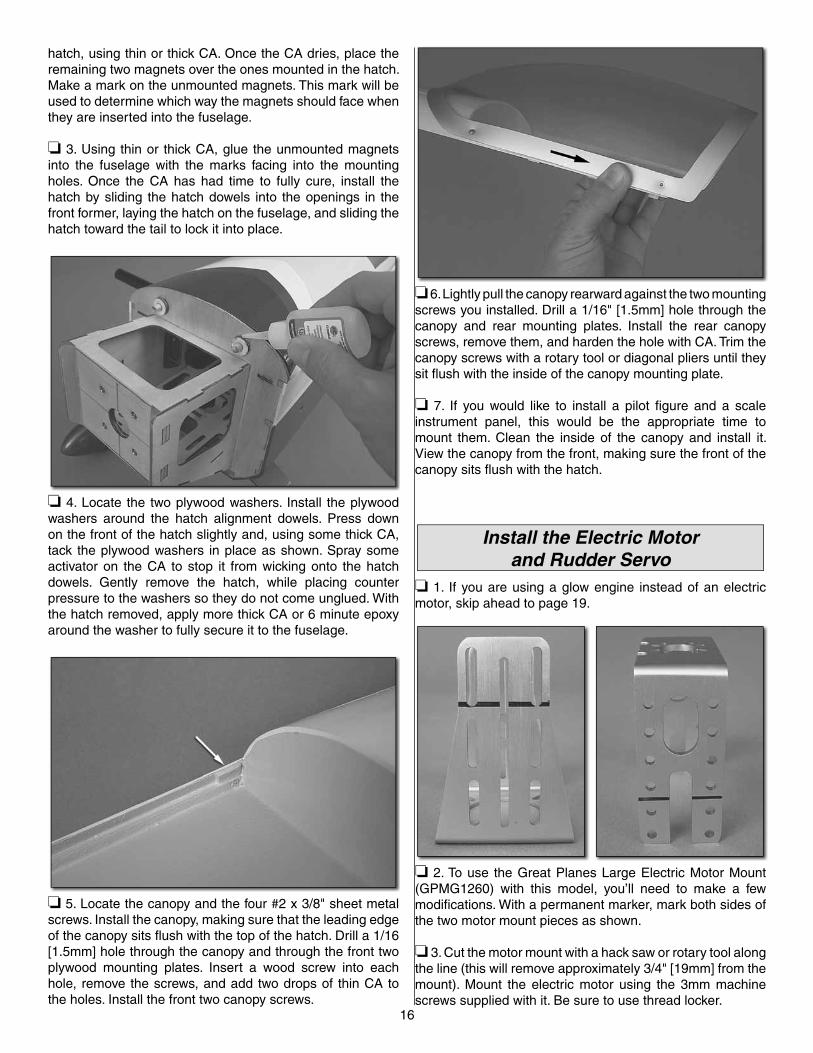
❏ 5. Locate the canopy and the four #2 x 3/8" sheet metal screws. Install the canopy, making sure that the leading edge of the canopy sits fl ush with the top of the hatch. Drill a 1/16 [1.5mm] hole through the canopy and through the front two plywood mounting plates. Insert a wood screw into each hole, remove the screws, and add two drops of thin CA to the holes. Install the front two canopy screws.
❏ 6. Lightly pull the canopy rearward against the two mounting screws you installed. Drill a 1/16" [1.5mm] hole through the canopy and rear mounting plates. Install the rear canopy screws, remove them, and harden the hole with CA. Trim the canopy screws with a rotary tool or diagonal pliers until they sit fl ush with the inside of the canopy mounting plate.
❏ 7. If you would like to install a pilot fi gure and a scale instrument panel, this would be the appropriate time to mount them. Clean the inside of the canopy and install it. View the canopy from the front, making sure the front of the canopy sits fl ush with the hatch.
Install the Electric Motor and Rudder Servo
❏ 1. If you are using a glow engine instead of an electric motor, skip ahead to page 19.
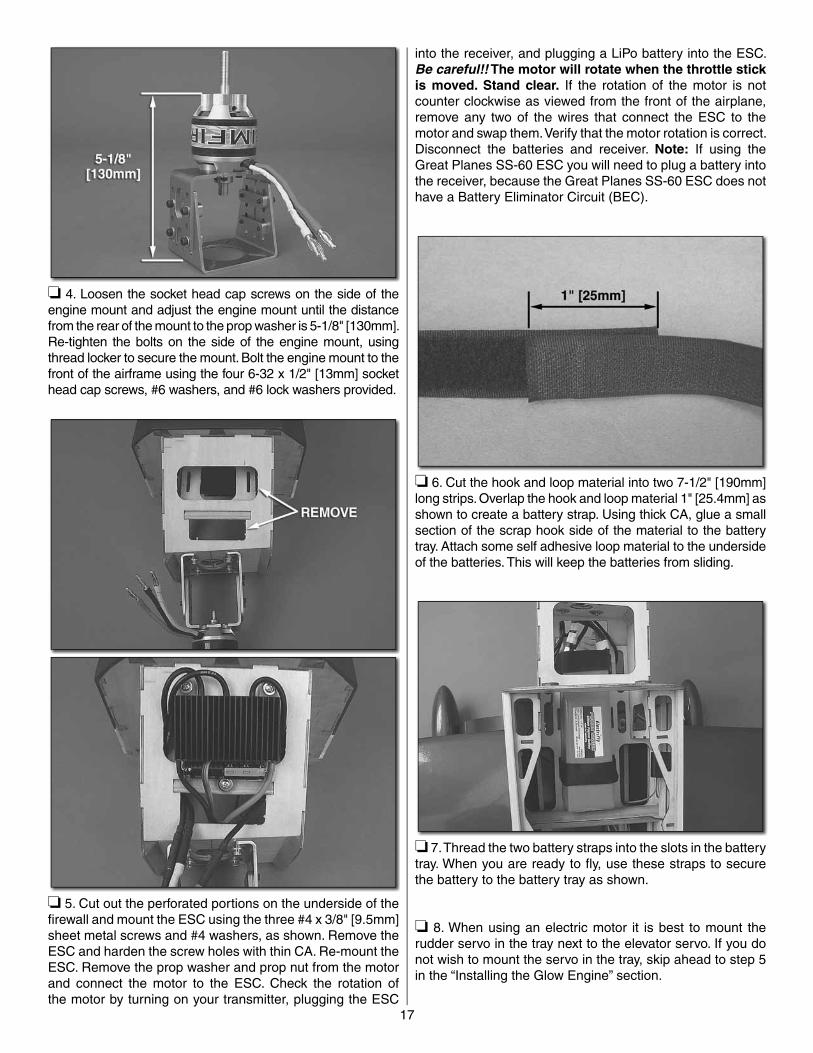
❏ 2. To use the Great Planes Large Electric Motor Mount (GPMG1260) with this model, you’ll need to make a few modifi cations. With a permanent marker, mark both sides of the two motor mount pieces as shown.
❏ 3. Cut the motor mount with a hack saw or rotary tool along the line (this will remove approximately 3/4" [19mm] from the mount). Mount the electric motor using the 3mm machine screws supplied with it. Be sure to use thread locker.
17
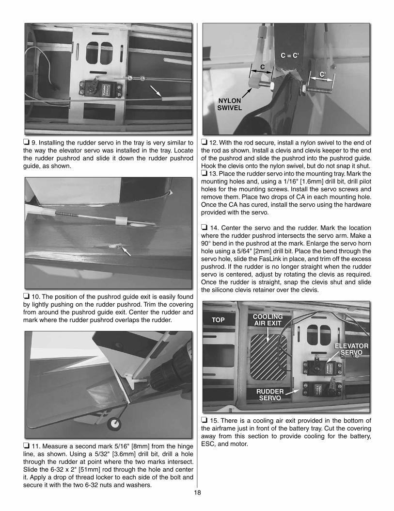
❏ 4. Loosen the socket head cap screws on the side of the engine mount and adjust the engine mount until the distance from the rear of the mount to the prop washer is 5-1/8" [130mm]. Re-tighten the bolts on the side of the engine mount, using thread locker to secure the mount. Bolt the engine mount to the front of the airframe using the four 6-32 x 1/2" [13mm] socket head cap screws, #6 washers, and #6 lock washers provided.
❏ 5. Cut out the perforated portions on the underside of the fi rewall and mount the ESC using the three #4 x 3/8" [9.5mm] sheet metal screws and #4 washers, as shown. Remove the ESC and harden the screw holes with thin CA. Re-mount the ESC. Remove the prop washer and prop nut from the motor and connect the motor to the ESC. Check the rotation of the motor by turning on your transmitter, plugging the ESC
into the receiver, and plugging a LiPo battery into the ESC. Be careful!! The motor will rotate when the throttle stick is moved. Stand clear. If the rotation of the motor is not counter clockwise as viewed from the front of the airplane, remove any two of the wires that connect the ESC to the motor and swap them. Verify that the motor rotation is correct. Disconnect the batteries and receiver. Note: If using the Great Planes SS-60 ESC you will need to plug a battery into the receiver, because the Great Planes SS-60 ESC does not have a Battery Eliminator Circuit (BEC).
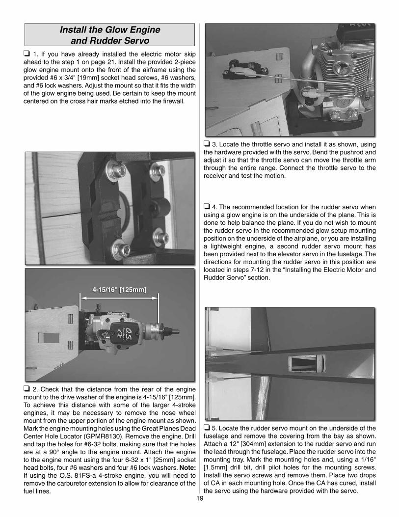
❏ 6. Cut the hook and loop material into two 7-1/2" [190mm] long strips. Overlap the hook and loop material 1" [25.4mm] as shown to create a battery strap. Using thick CA, glue a small section of the scrap hook side of the material to the battery tray. Attach some self adhesive loop material to the underside of the batteries. This will keep the batteries from sliding.
❏ 7. Thread the two battery straps into the slots in the battery tray. When you are ready to fl y, use these straps to secure the battery to the battery tray as shown.
❏ 8. When using an electric motor it is best to mount the rudder servo in the tray next to the elevator servo. If you do not wish to mount the servo in the tray, skip ahead to step 5 in the “Installing the Glow Engine” section.
18
❏ 9. Installing the rudder servo in the tray is very similar to the way the elevator servo was installed in the tray. Locate the rudder pushrod and slide it down the rudder pushrod guide, as shown.
❏ 10. The position of the pushrod guide exit is easily found by lightly pushing on the rudder pushrod. Trim the covering from around the pushrod guide exit. Center the rudder and mark where the rudder pushrod overlaps the rudder.
❏ 11. Measure a second mark 5/16" [8mm] from the hinge line, as shown. Using a 5/32" [3.6mm] drill bit, drill a hole through the rudder at point where the two marks intersect. Slide the 6-32 x 2" [51mm] rod through the hole and center it. Apply a drop of thread locker to each side of the bolt and secure it with the two 6-32 nuts and washers.
❏ 12. With the rod secure, install a nylon swivel to the end of the rod as shown. Install a clevis and clevis keeper to the end of the pushrod and slide the pushrod into the pushrod guide. Hook the clevis onto the nylon swivel, but do not snap it shut.❏ 13. Place the rudder servo into the mounting tray. Mark the mounting holes and, using a 1/16" [1.6mm] drill bit, drill pilot holes for the mounting screws. Install the servo screws and remove them. Place two drops of CA in each mounting hole. Once the CA has cured, install the servo using the hardware provided with the servo.
❏ 14. Center the servo and the rudder. Mark the location where the rudder pushrod intersects the servo arm. Make a 90° bend in the pushrod at the mark. Enlarge the servo horn hole using a 5/64" [2mm] drill bit. Place the bend through the servo hole, slide the FasLink in place, and trim off the excess pushrod. If the rudder is no longer straight when the rudder servo is centered, adjust by rotating the clevis as required. Once the rudder is straight, snap the clevis shut and slide the silicone clevis retainer over the clevis.
❏ 15. There is a cooling air exit provided in the bottom of the airframe just in front of the battery tray. Cut the covering away from this section to provide cooling for the battery, ESC, and motor.
19
Install the Glow Engineand Rudder Servo
❏ 1. If you have already installed the electric motor skip ahead to the step 1 on page 21. Install the provided 2-piece glow engine mount onto the front of the airframe using the provided #6 x 3/4" [19mm] socket head screws, #6 washers, and #6 lock washers. Adjust the mount so that it fi ts the width of the glow engine being used. Be certain to keep the mount centered on the cross hair marks etched into the fi rewall.
❏ 2. Check that the distance from the rear of the engine mount to the drive washer of the engine is 4-15/16" [125mm]. To achieve this distance with some of the larger 4-stroke engines, it may be necessary to remove the nose wheel mount from the upper portion of the engine mount as shown. Mark the engine mounting holes using the Great Planes Dead Center Hole Locator (GPMR8130). Remove the engine. Drill and tap the holes for #6-32 bolts, making sure that the holes are at a 90° angle to the engine mount. Attach the engine to the engine mount using the four 6-32 x 1" [25mm] socket head bolts, four #6 washers and four #6 lock washers. Note: If using the O.S. 81FS-a 4-stroke engine, you will need to remove the carburetor extension to allow for clearance of the fuel lines.
❏ 3. Locate the throttle servo and install it as shown, using the hardware provided with the servo. Bend the pushrod and adjust it so that the throttle servo can move the throttle arm through the entire range. Connect the throttle servo to the receiver and test the motion.
❏ 4. The recommended location for the rudder servo when using a glow engine is on the underside of the plane. This is done to help balance the plane. If you do not wish to mount the rudder servo in the recommended glow setup mounting position on the underside of the airplane, or you are installing a lightweight engine, a second rudder servo mount has been provided next to the elevator servo in the fuselage. The directions for mounting the rudder servo in this position are located in steps 7-12 in the “Installing the Electric Motor and Rudder Servo” section.
❏ 5. Locate the rudder servo mount on the underside of the fuselage and remove the covering from the bay as shown. Attach a 12" [304mm] extension to the rudder servo and run the lead through the fuselage. Place the rudder servo into the mounting tray. Mark the mounting holes and, using a 1/16" [1.5mm] drill bit, drill pilot holes for the mounting screws. Install the servo screws and remove them. Place two drops of CA in each mounting hole. Once the CA has cured, install the servo using the hardware provided with the servo.
20
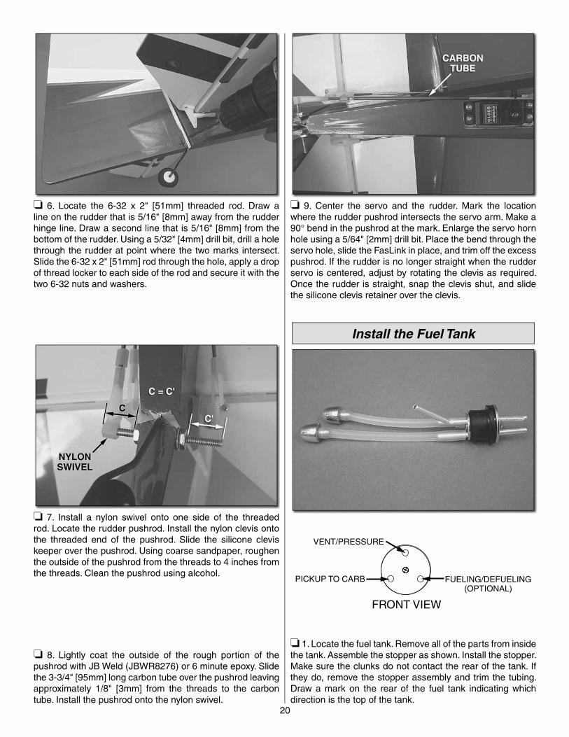
❏ 6. Locate the 6-32 x 2" [51mm] threaded rod. Draw a line on the rudder that is 5/16" [8mm] away from the rudder hinge line. Draw a second line that is 5/16" [8mm] from the bottom of the rudder. Using a 5/32" [4mm] drill bit, drill a hole through the rudder at point where the two marks intersect. Slide the 6-32 x 2" [51mm] rod through the hole, apply a drop of thread locker to each side of the rod and secure it with the two 6-32 nuts and washers.
❏ 7. Install a nylon swivel onto one side of the threaded rod. Locate the rudder pushrod. Install the nylon clevis onto the threaded end of the pushrod. Slide the silicone clevis keeper over the pushrod. Using coarse sandpaper, roughen the outside of the pushrod from the threads to 4 inches from the threads. Clean the pushrod using alcohol.
❏ 8. Lightly coat the outside of the rough portion of the pushrod with JB Weld (JBWR8276) or 6 minute epoxy. Slide the 3-3/4" [95mm] long carbon tube over the pushrod leaving approximately 1/8" [3mm] from the threads to the carbon tube. Install the pushrod onto the nylon swivel.
❏ 9. Center the servo and the rudder. Mark the location where the rudder pushrod intersects the servo arm. Make a 90° bend in the pushrod at the mark. Enlarge the servo horn hole using a 5/64" [2mm] drill bit. Place the bend through the servo hole, slide the FasLink in place, and trim off the excess pushrod. If the rudder is no longer straight when the rudder servo is centered, adjust by rotating the clevis as required. Once the rudder is straight, snap the clevis shut, and slide the silicone clevis retainer over the clevis.
Install the Fuel Tank
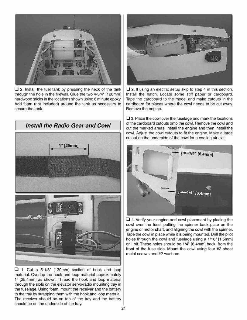
VENT/PRESSURE
FUELING/DEFUELING(OPTIONAL)
FRONT VIEW
PICKUP TO CARB
❏ 1. Locate the fuel tank. Remove all of the parts from inside the tank. Assemble the stopper as shown. Install the stopper. Make sure the clunks do not contact the rear of the tank. If they do, remove the stopper assembly and trim the tubing. Draw a mark on the rear of the fuel tank indicating which direction is the top of the tank.
21
❏ 2. Install the fuel tank by pressing the neck of the tank through the hole in the fi rewall. Glue the two 4-3/4" [120mm] hardwood sticks in the locations shown using 6 minute epoxy. Add foam (not included) around the tank as necessary to secure the tank.
Install the Radio Gear and Cowl
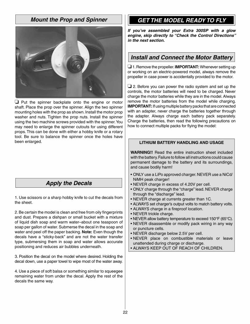
❏ 1. Cut a 5-1/8" [130mm] section of hook and loop material. Overlap the hook and loop material approximately 1" [25.4mm] as shown. Thread the hook and loop material through the slots on the elevator servo/radio mounting tray in the fuselage. Using foam, mount the receiver and the battery to the tray by strapping them with the hook and loop material. The receiver should be on top of the tray and the battery should be on the underside of the tray.
❏ 2. If using an electric setup skip to step 4 in this section. Install the hatch. Locate some stiff paper or cardboard. Tape the cardboard to the model and make cutouts in the cardboard for places where the cowl needs to be cut away. Remove the engine.
❏ 3. Place the cowl over the fuselage and mark the locations of the cardboard cutouts onto the cowl. Remove the cowl and cut the marked areas. Install the engine and then install the cowl. Adjust the cowl cutouts to fi t the engine. Make a large cutout on the underside of the cowl for a cooling air exit.
❏ 4. Verify your engine and cowl placement by placing the cowl over the fuse, putting the spinner back plate on the engine or motor shaft, and aligning the cowl with the spinner. Tape the cowl in place while it is being mounted. Drill the pilot holes through the cowl and fuselage using a 1/16" [1.5mm] drill bit. These holes should be 1/4" [6.4mm] back, from the front of the fuse side. Mount the cowl using four #2 sheet metal screws and #2 washers.
22
Mount the Prop and Spinner
❏ Put the spinner backplate onto the engine or motor shaft. Place the prop over the spinner. Align the two spinner mounting holes with the prop as shown. Install the motor prop washer and nuts. Tighten the prop nuts. Install the spinner using the two machine screws provided with the spinner. You may need to enlarge the spinner cutouts for using different props. This can be done with either a hobby knife or a rotary tool. Be sure to balance the spinner once the holes have been enlarged.
Apply the Decals
1. Use scissors or a sharp hobby knife to cut the decals from the sheet.
2. Be certain the model is clean and free from oily fi ngerprints and dust. Prepare a dishpan or small bucket with a mixture of liquid dish soap and warm water–about one teaspoon of soap per gallon of water. Submerse the decal in the soap and water and peel off the paper backing. Note: Even though the decals have a “sticky-back” and are not the water transfer type, submersing them in soap and water allows accurate positioning and reduces air bubbles underneath.
3. Position the decal on the model where desired. Holding the decal down, use a paper towel to wipe most of the water away.
4. Use a piece of soft balsa or something similar to squeegee remaining water from under the decal. Apply the rest of the decals the same way.
GET THE MODEL READY TO FLY
If you’ve assembled your Extra 300SP with a glow engine, skip directly to “Check the Control Directions” in the next section.
Install and Connect the Motor Battery
❏ 1. Remove the propeller. IMPORTANT: Whenever setting up or working on an electric-powered model, always remove the propeller in case power is accidentally provided to the motor.
❏ 2. Before you can power the radio system and set up the controls, the motor batteries will need to be charged. Never charge the motor batteries while they are in the model. Always remove the motor batteries from the model while charging. IMPORTANT: If using multiple battery packs that are connected with an adapter, never charge the batteries together through the adapter. Always charge each battery pack separately. Charge the batteries, then read the following precautions on how to connect multiple packs for fl ying the model:
LITHIUM BATTERY HANDLING AND USAGE
WARNING!! Read the entire instruction sheet included with the battery. Failure to follow all instructions could cause permanent damage to the battery and its surroundings, and cause bodily harm!
• ONLY use a LiPo approved charger. NEVER use a NiCd/NiMH peak charger!
• NEVER charge in excess of 4.20V per cell.• ONLY charge through the “charge” lead. NEVER charge
through the “discharge” lead.• NEVER charge at currents greater than 1C.• ALWAYS set charger’s output volts to match battery volts.• ALWAYS charge in a fi reproof location.• NEVER trickle charge.• NEVER allow battery temperature to exceed 150°F (65°C).• NEVER disassemble or modify pack wiring in any way
or puncture cells.• NEVER discharge below 2.5V per cell.• NEVER place on combustible materials or leave
unattended during charge or discharge.• ALWAYS KEEP OUT OF REACH OF CHILDREN.
23
BATTERY PRECAUTIONS
There are two ways to connect multiple battery packs: In Series and in Parallel.
These are two 3200mAh batteries (one 11.1Vand the other 7.4V). When joined in SERIES,the result will be a 18.5V, 3200 mAh battery.
It’s okay to connect batteries with different voltages inseries to achieve the new, desired voltage.
This is a SERIES batteryadapter (GPMM3143)that connects twobatteries in series.
11.1V (3-Cell)GPMP0613
OKAY
7.4V (2-Cell)GPMP0613
❏ 1. Connecting batteries in “Series” means to connect the (+)’s to the (–)’s and the (–)’s to the (+)’s. This combines the voltages of the batteries, but the capacity remains the same.
These two 1500mAh batteries (both 11.1V) arebeing joined in PARALLEL. The result will beone 11.1V, 3000mAh battery.
This is a PARALLEL batteryadapter (GPMM3142) thatconnects two batteries in parallel.
11.1V (3-Cell)GPMP0613
OKAY
11.1V (3-Cell)GPMP0613
❏ 2. Connecting batteries in “Parallel” means to connect the (+)’s to the (+)’s and the (-)’s to the (-)’s. This combines the capacities of the batteries, but the voltage remains the same.
Differentvoltages
PARALLELadapter
11.1V (3-Cell)3200mAh
7.4V (2-Cell)3200mAh
NO!!!
NEVER connect battery packs with different voltages in parallel! Only combine them in series. Otherwise, the batteries with lower voltage will try to “equalize” with the batteries that have a higher voltage. Current will fl ow from the higher voltage battery into the lower one, essentially “charging” the lower voltage battery pack. This situation will likely cause heat and possibly a fi re.
Differentcapacities
11.1V (3-Cell)3200mAh
NO!!!
11.1V (3-Cell)1250mAh
NEVER connect battery packs with different capacities in series or in parallel.
Check the Control Directions
❏ 1. IMPORTANT: If your Extra is powered by an electric motor, remove the propeller if you haven’t done so already.
❏ 2. Turn on the transmitter and receiver and center the trims. If necessary, remove the servo arms from the servos and reposition them so they are centered. Reinstall the screws that hold on the servo arms.
❏ 3. With the transmitter and receiver still on, check all the control surfaces to see if they are centered. If necessary, adjust the clevises on the pushrods to center the control surfaces.
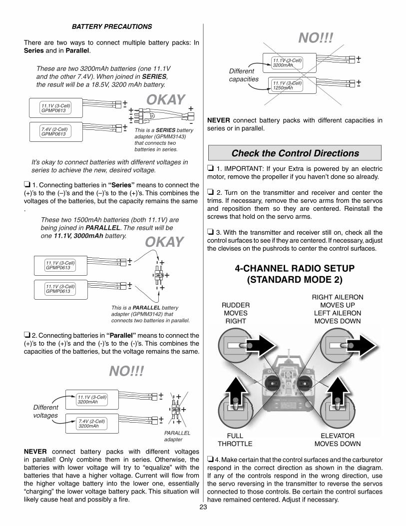
FULLTHROTTLE
RUDDERMOVESRIGHT
ELEVATORMOVES DOWN
RIGHT AILERONMOVES UP
LEFT AILERONMOVES DOWN
4-CHANNEL RADIO SETUP(STANDARD MODE 2)
❏ 4. Make certain that the control surfaces and the carburetor respond in the correct direction as shown in the diagram. If any of the controls respond in the wrong direction, use the servo reversing in the transmitter to reverse the servos connected to those controls. Be certain the control surfaces have remained centered. Adjust if necessary.
24
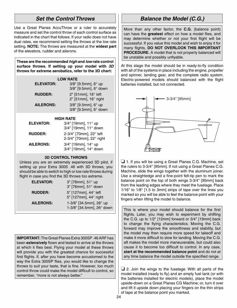
Set the Control Throws
Use a Great Planes AccuThrow or a ruler to accurately measure and set the control throw of each control surface as indicated in the chart that follows. If your radio does not have dual rates, we recommend setting the throws at the low rate setting. NOTE: The throws are measured at the widest part of the elevators, rudder and ailerons.
These are the recommended high and low rate control surface throws. If setting up your model with 3D throws for extreme aerobatics, refer to the 3D chart:
LOW RATE ELEVATOR: 3/8" [9.5mm], 6° up 3/8" [9.5mm], 6° down
RUDDER: 2" [51mm], 16° left 2" [51mm], 16° right
AILERONS: 3/8" [9.5mm], 6° up 3/8" [9.5mm], 6° down
HIGH RATE ELEVATOR: 3/4" [19mm], 11° up 3/4" [19mm], 11° down
RUDDER: 2-3/4" [70mm], 22° left 2-3/4" [70mm], 22° right
AILERONS: 3/4" [19mm], 14° up 3/4" [19mm], 14° down
3D CONTROL THROWSUnless you are an extremely experienced 3D pilot, if setting up your Extra 300S .46 with 3D throws, you should be able to switch to high or low rate throws during fl ight in case you fi nd the 3D throws too extreme.
ELEVATOR: 3" [76mm], 51° up 3" [76mm], 51° down
RUDDER: 5" [127mm], 44° left 5" [127mm], 44° right
AILERONS: 1-3/8" [34.5mm], 26° up 1-3/8" [34.5mm], 26° down
IMPORTANT: The Great Planes Extra 300SP .46 ARF has been extensively fl own and tested to arrive at the throws at which it fl ies best. Flying your model at these throws will provide you with the greatest chance for successful fi rst fl ights. If, after you have become accustomed to the way the Extra 300SP fl ies, you would like to change the throws to suit your taste, that is fi ne. However, too much control throw could make the model diffi cult to control, so remember, “more is not always better.”
Balance the Model (C.G.)
More than any other factor, the C.G. (balance point) can have the greatest effect on how a model fl ies, and may determine whether or not your fi rst fl ight will be successful. If you value this model and wish to enjoy it for many fl ights, DO NOT OVERLOOK THIS IMPORTANT PROCEDURE. A model that is not properly balanced will be unstable and possibly unfl yable.
At this stage the model should be in ready-to-fl y condition with all of the systems in place including the engine, propeller and spinner, landing gear, and the complete radio system. Electric-powered models should balanced with the fl ight batteries installed, but not connected.
3-3/4" [95mm]
❏ 1. If you will be using a Great Planes C.G. Machine, set the rulers to 3-3/4" [95mm]. If not using a Great Planes C.G. Machine, slide the wings together with the aluminum joiner. Use a straightedge and a fi ne-point felt-tip pen to mark the balance point on the top of both wings 3-3/4" [95mm] back from the leading edges where they meet the fuselage. Place 1/16" to 1/8" [1.5 to 3mm] strips of tape over the lines you marked so you will be able to feel the balance point with your fi ngers when lifting the model to balance.
This is where your model should balance for the fi rst fl ights. Later, you may wish to experiment by shifting the C.G. up to 1/2" [12mm] forward or 3/4" [19mm] back to change the fl ying characteristics. Moving the C.G. forward may improve the smoothness and stability, but the model may then require more speed for takeoff and make it more diffi cult to slow for landing. Moving the C.G. aft makes the model more maneuverable, but could also cause it to become too diffi cult to control. In any case, start at the recommended balance point and do not at any time balance the model outside the specifi ed range.
❏ 2. Join the wings to the fuselage. With all parts of the model installed (ready to fl y) and an empty fuel tank (or with the batteries installed for electric models), place the model upside-down on a Great Planes CG Machine; or, turn it over and lift it upside down placing your fi ngers on the thin strips of tape at the balance point you marked.
25
❏ 3. If the tail drops, the model is “tail heavy” and the battery pack and/or receiver must be shifted forward or weight must be added to the nose to balance. If the nose drops, the model is “nose heavy” and the battery pack and/or receiver must be shifted aft or weight must be added to the tail to balance. If possible, relocate the battery pack and receiver to minimize or eliminate any additional ballast required. If additional weight is required, use Great Planes (GPMQ4485) “stick on” lead. A good place to add stick-on nose weight is to the back of the fi rewall inside the fuselage (don’t attach weight to the cowl—it is not intended to support weight). Begin by placing incrementally increasing amounts of weight on the fuselage over the location where it will be permanently attached inside the model until you can get it to balance. Once you have determined the amount of weight required, it can be permanently attached. If required, tail weight may be added by cutting open the bottom of the fuselage and gluing it permanently inside.
Note: Do not rely upon the adhesive on the back of the lead weight to permanently hold it in place. Over time, fuel and exhaust residue may soften the adhesive and cause the weight to fall off. Use #2 sheet metal screws, RTV silicone or epoxy to permanently hold the weight in place.
❏ 4. IMPORTANT: If you found it necessary to add any weight, recheck the C.G. after the weight has been installed.
Balance the Model Laterally
❏ 1. With the wing level, have an assistant help you lift the model by the engine propeller shaft and the bottom of the fuselage under the trailing edge of the horizontal stabilizer. Do this several times.
❏ 2. If one wing always drops when you lift the model, it means that side is heavy. Balance the airplane by adding weight to the other wing tip. An airplane that has been laterally balanced will track better in loops and other maneuvers.
PREFLIGHT
Identify Your Model
No matter if you fl y at an AMA sanctioned R/C club site or if you fl y somewhere on your own, you should always have your name, address, telephone number and AMA number on or inside your model. It is required at all AMA R/C club fl ying sites and AMA sanctioned fl ying events. Fill out the identifi cation tag on the decal sheet and place it on or inside your model.
Charge the Batteries
Follow the battery charging instructions that came with your radio control system to charge the batteries. You should always charge your transmitter and receiver batteries the night before you go fl ying, and at other times as recommended by the radio manufacturer.
CAUTION: Unless the instructions that came with your radio system state differently, the initial charge on new transmitter and receiver batteries should be done for 15 hours using the slow-charger that came with the radio system. This will "condition" the batteries so that the next charge may be done using the fast-charger of your choice. If the initial charge is done with a fast-charger, the batteries may not reach their full capacity and you may be fl ying with batteries that are only partially charged.
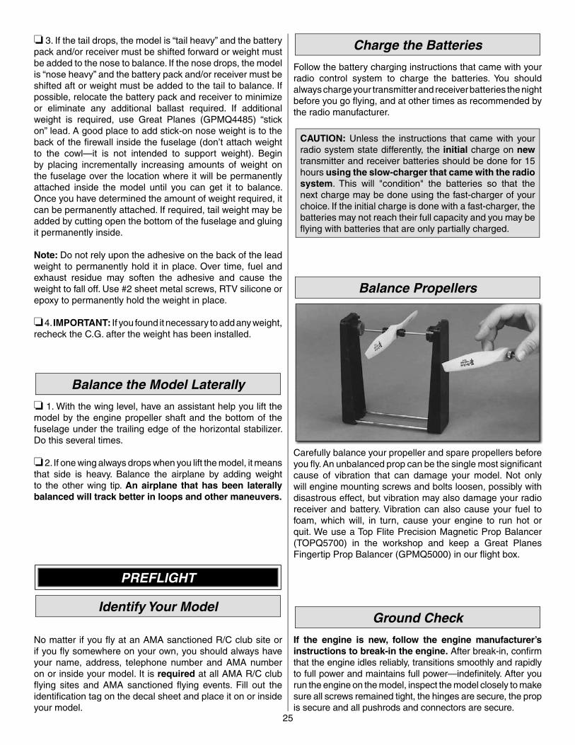
Balance Propellers
Carefully balance your propeller and spare propellers before you fl y. An unbalanced prop can be the single most signifi cant cause of vibration that can damage your model. Not only will engine mounting screws and bolts loosen, possibly with disastrous effect, but vibration may also damage your radio receiver and battery. Vibration can also cause your fuel to foam, which will, in turn, cause your engine to run hot or quit. We use a Top Flite Precision Magnetic Prop Balancer(TOPQ5700) in the workshop and keep a Great Planes Fingertip Prop Balancer (GPMQ5000) in our fl ight box.
Ground Check
If the engine is new, follow the engine manufacturer’s instructions to break-in the engine. After break-in, confi rm that the engine idles reliably, transitions smoothly and rapidly to full power and maintains full power—indefi nitely. After you run the engine on the model, inspect the model closely to make sure all screws remained tight, the hinges are secure, the prop is secure and all pushrods and connectors are secure.
26
Range Check
Ground check the operational range of your radio before the fi rst fl ight of the day. With the transmitter antenna collapsed and the receiver and transmitter on, you should be able to walk at least 100 feet away from the model and still have control. Have an assistant stand by your model and, while you work the controls, tell you what the control surfaces are doing. Repeat this test with the engine running at various speeds with an assistant holding the model, using hand signals to show you what is happening. If the control surfaces do not respond correctly, do not fl y! Find and correct the problem fi rst. Look for loose servo connections or broken wires, corroded wires on old servo connectors, poor solder joints in your battery pack or a defective cell, or a damaged receiver crystal from a previous crash.
ELECTRIC MOTOR & ENGINESAFETY PRECAUIONS
The following precautions apply both to electric motors and gas and glow engines. Failure to follow these safety precautions may result in severe injury to yourself and others.
• Keep all engine fuel in a safe place, away from high heat, sparks or fl ames, as fuel is very fl ammable. Do not smoke near the engine or fuel; and remember that engine exhaust gives off a great deal of deadly carbon monoxide. Therefore do not run the engine in a closed room or garage.
• Get help from an experienced pilot when learning tooperate engines.
• Use safety glasses when starting or running engines.• Do not run the engine in an area of loose gravel or sand;
the propeller may throw such material in your face or eyes.• Keep your face and body as well as all spectators away
from the plane of rotation of the propeller as you start and run the engine.
• Keep these items away from the prop: loose clothing, shirt sleeves, ties, scarfs, long hair or loose objects such as pencils or screwdrivers that may fall out of shirt or jacket pockets into the prop.
• Use a "chicken stick" or electric starter to start the engine. Do not use your fi ngers to fl ip the propeller. Make certain the glow plug clip or connector is secure so that it will not pop off or otherwise get into the running propeller.
• Make all engine adjustments from behind therotating propeller.
• The engine gets hot! Do not touch it during or right after operation. Make sure fuel lines are in good condition so fuel will not leak onto a hot engine, causing a fi re.
• To stop a glow engine, cut off the fuel supply by closing off the fuel line or following the engine manufacturer's recommendations. Do not use hands, fi ngers or any other body part to try to stop the engine. To stop a gasoline powered engine an on/off switch should be connected to the engine coil. Do not throw anything into the propeller of a running engine.
These precautions apply only to electric-powered models:• Always remove the LiPo battery from the plane
before charging. • Always use a charger designed to charge LiPo batteries for
charging the LiPo fl ight battery. • Never leave the LiPo battery unattended while charging. If
the battery becomes hot, discontinue charging.
AMA SAFETY CODE (EXCERPTS)
Read and abide by the following excerpts from the Academy of Model Aeronautics Safety Code. For the complete Safety Code refer to Model Aviation magazine, the AMA web site or the Code that came with your AMA license.
General
1) I will not fl y my model aircraft in sanctioned events, air shows, or model fl ying demonstrations until it has been proven to be airworthy by having been previously, successfully fl ight tested.
2) I will not fl y my model aircraft higher than approximately 400 feet within 3 miles of an airport without notifying the airport operator. I will give right-of-way and avoid fl ying in the proximity of full-scale aircraft. Where necessary, an observer shall be utilized to supervise fl ying to avoid having models fl y in the proximity of full-scale aircraft.
3) Where established, I will abide by the safety rules for the fl ying site I use, and I will not willfully and deliberately fl y my models in a careless, reckless and/or dangerous manner.
5) I will not fl y my model unless it is identifi ed with my name and address or AMA number, on or in the model. Note: This does not apply to models while being fl own indoors.
7) I will not operate models with pyrotechnics (any device that explodes, burns, or propels a projectile of any kind).
Radio Control
1) I will have completed a successful radio equipment ground check before the fi rst fl ight of a new or repaired model.
2) I will not fl y my model aircraft in the presence of spectators until I become a qualifi ed fl ier, unless assisted by an experienced helper.
3) At all fl ying sites a straight or curved line(s) must be established in front of which all fl ying takes place with the other side for spectators. Only personnel involved with fl ying the aircraft are allowed at or in the front of the fl ight line. Intentional fl ying behind the fl ight line is prohibited.
4) I will operate my model using only radio control frequencies currently allowed by the Federal Communications Commission.
5) I will not knowingly operate my model within three miles of any pre-existing fl ying site except in accordance with the frequency sharing agreement listed [in the complete AMA Safety Code].
9) Under no circumstances may a pilot or other person touch a powered model in fl ight; nor should any part of the model other than the landing gear, intentionally touch the ground, except while landing.
27
CHECK LIST
During the last few moments of preparation your mind may be elsewhere anticipating the excitement of the fi rst fl ight. Because of this, you may be more likely to overlook certain checks and procedures that should be performed before the model is fl own. To help avoid this, a check list is provided to make sure these important areas are not overlooked. Many are covered in the instruction manual, so where appropriate, refer to the manual for complete instructions. Be sure to check the items off as they are completed.
❏ 1. Fuel proof all areas exposed to fuel or exhaust residue such as the cowl mounting blocks, wing saddle area, etc.
❏ 2. Check the C.G. according to the measurements provided in the manual.
❏ 3. Be certain the battery and receiver are securely mounted in the fuse. Simply stuffi ng them into place with foam rubber is not suffi cient.
❏ 4. Extend your receiver antenna and make sure it has a strain relief inside the fuselage to keep tension off the solder joint inside the receiver.
❏ 5. Balance your model laterally as explained in the instructions.❏ 6. Use threadlocking compound to secure critical
fasteners such as the set screws that hold the wheel axles to the struts, screws that hold the carburetor arm (if applicable), screw-lock pushrod connectors, etc.
❏ 7. Add a drop of oil to the axles so the wheels will turn freely.❏ 8. Make sure all hinges are securely glued in place.❏ 9. Reinforce holes for wood screws with thin CA where
appropriate (servo mounting screws, cowl mounting screws, etc.).
❏ 10. Confi rm that all controls operate in the correct direction and the throws are set up according to the manual.
❏ 11. Make sure there are silicone retainers on all the clevises and that all servo arms are secured to the servos with the screws included with your radio.
❏ 12. Secure connections between servo wires and Y-connectors or servo extensions, and the connection between your battery pack and the on/off switch with vinyl tape, heat shrink tubing or special clips suitable for that purpose.
❏ 13. Make sure any servo extension cords you may have used do not interfere with other systems (servo arms, pushrods, etc.).
❏ 14. Secure the pressure tap (if used) to the muffl er with high temp RTV silicone, thread locking compound or J.B. Weld.
❏ 15. Make sure the fuel lines are connected and arenot kinked.
❏ 16. Balance your propeller (and spare propellers).❏ 17. Tighten the propeller nut and spinner.❏ 18. Place your name, address, AMA number and telephone
number on or inside your model.❏ 19. Cycle your receiver battery pack (if necessary) and
make sure it is fully charged.❏ 20. If you wish to photograph your model, do so before
your fi rst fl ight.❏ 21. Range check your radio when you get to the fl ying fi eld.
FLYING
Mount the Wing
Mount the wings to the fuselage. It will be helpful to have a Great Planes 4-in-1 Installation Tool for tightening the wing bolts (GPMR8035). Don’t forget to connect the aileron servo extensions to the Y-connector coming from the aileron channel in the receiver. Be sure the wires will not get caught on any of the servos or pushrods inside the fuselage. If your Extra is powered by an electric motor, be certain the batteries are securely strapped into place. Mount the canopy hatch with the screws and a drop of threadlocker on the threads.
The Great Planes Extra 300SP .46 ARF is a great-fl ying model that fl ies smoothly and predictably. The Extra does not, however, possess the self-recovery characteristics of a primary R/C trainer and should be fl own only by experienced R/C pilots.
Fuel Mixture Adjustment (Glow Engines)
A fully cowled engine may run at a higher temperature than an un-cowled engine. For this reason, the fuel mixture should be richened so the engine runs at about 200 rpm below peak speed. By running the engine slightly rich, you will help prevent dead-stick landings caused by overheating.
Takeoff
Before you get ready to takeoff, see how the model handles on the ground by doing a few practice runs at low speeds on the runway. Hold “up” elevator to keep the tail wheel on the ground. If necessary, adjust the tail wheel so the model will roll straight down the runway. If you need to calm your nerves before the maiden fl ight, shut the engine down and bring the model back into the pits. Top off the fuel, and then check all fasteners and control linkages for peace of mind.
Remember to takeoff into the wind. When you’re ready, point the model straight down the runway, and hold a bit of up elevator to keep the tail on the ground to maintain tail wheel steering. Then gradually advance the throttle. As the model gains speed, decrease up elevator, allowing the tail to come off the ground. One of the most important things to remember with tail-draggers that have big engines is to always be ready to apply right rudder to counteract engine torque. Gain as much speed as your runway and fl ying site will practically allow before gently applying up elevator, lifting the model into the air. At this moment it is likely that you will need to apply more right rudder to counteract engine torque. Be smooth on the elevator stick, allowing the model to establish a gentle climb to a safe altitude before turning into the traffi c pattern.
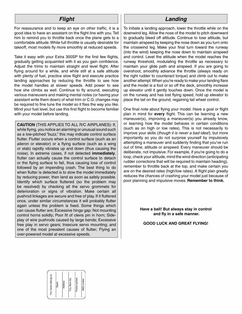
Flight
For reassurance and to keep an eye on other traffi c, it is a good idea to have an assistant on the fl ight line with you. Tell him to remind you to throttle back once the plane gets to a comfortable altitude. While full throttle is usually desirable for takeoff, most models fl y more smoothly at reduced speeds.
Take it easy with your Extra 300SP for the fi rst few fl ights, gradually getting acquainted with it as you gain confi dence. Adjust the trims to maintain straight and level fl ight. After fl ying around for a while, and while still at a safe altitude with plenty of fuel, practice slow fl ight and execute practice landing approaches by reducing the throttle to see how the model handles at slower speeds. Add power to see how she climbs as well. Continue to fl y around, executing various maneuvers and making mental notes (or having your assistant write them down) of what trim or C.G. changes may be required to fi ne tune the model so it fl ies the way you like. Mind your fuel level, but use this fi rst fl ight to become familiar with your model before landing.
CAUTION (THIS APPLIES TO ALL R/C AIRPLANES): If, while fl ying, you notice an alarming or unusual sound such as a low-pitched “buzz,” this may indicate control surface fl utter. Flutter occurs when a control surface (such as an aileron or elevator) or a fl ying surface (such as a wing or stab) rapidly vibrates up and down (thus causing the noise). In extreme cases, if not detected immediately, fl utter can actually cause the control surface to detach or the fl ying surface to fail, thus causing loss of control followed by an impending crash. The best thing to do when fl utter is detected is to slow the model immediately by reducing power, then land as soon as safely possible. Identify which surface fl uttered (so the problem may be resolved) by checking all the servo grommets for deterioration or signs of vibration. Make certain all pushrod linkages are secure and free of play. If it fl uttered once, under similar circumstances it will probably fl utter again unless the problem is fi xed. Some things which can cause fl utter are; Excessive hinge gap; Not mounting control horns solidly; Poor fi t of clevis pin in horn; Side-play of wire pushrods caused by large bends; Excessive free play in servo gears; Insecure servo mounting; and one of the most prevalent causes of fl utter; Flying an over-powered model at excessive speeds.
Landing
To initiate a landing approach, lower the throttle while on the downwind leg. Allow the nose of the model to pitch downward to gradually bleed off altitude. Continue to lose altitude, but maintain airspeed by keeping the nose down as you turn onto the crosswind leg. Make your fi nal turn toward the runway (into the wind) keeping the nose down to maintain airspeed and control. Level the attitude when the model reaches the runway threshold, modulating the throttle as necessary to maintain your glide path and airspeed. If you are going to overshoot, smoothly advance the throttle (always ready on the right rudder to counteract torque) and climb out to make another attempt. When you’re ready to make your landing fl are and the model is a foot or so off the deck, smoothly increase up elevator until it gently touches down. Once the model is on the runway and has lost fl ying speed, hold up elevator to place the tail on the ground, regaining tail wheel control.
One fi nal note about fl ying your model. Have a goal or fl ight plan in mind for every fl ight. This can be learning a new maneuver(s), improving a maneuver(s) you already know, or learning how the model behaves in certain conditions (such as on high or low rates). This is not necessarily to improve your skills (though it is never a bad idea!), but more importantly so you do not surprise yourself by impulsively attempting a maneuver and suddenly fi nding that you’ve run out of time, altitude or airspeed. Every maneuver should be deliberate, not impulsive. For example, if you’re going to do a loop, check your altitude, mind the wind direction (anticipating rudder corrections that will be required to maintain heading), remember to throttle back at the top, and make certain you are on the desired rates (high/low rates). A fl ight plan greatly reduces the chances of crashing your model just because of poor planning and impulsive moves. Remember to think.
Have a ball! But always stay in control and fl y in a safe manner.
GOOD LUCK AND GREAT FLYING!


![INSTRUCTION MANUAL - Hobbicomanuals.hobbico.com/gpm/gpma1330-manual-v1_2.pdf · INSTRUCTION MANUAL Length: 60" [1,524mm] Weight: 10.25 lbs ... SAFETY PRECAUTIONS ... Dead Center ™](https://img.pdfslide.net/doc/110x75/5aafd1a47f8b9a59478dd005/instruction-manual-manual-length-60-1524mm-weight-1025-lbs-safety-precautions.jpg)