Embed Size (px)
Citation preview

WING LOADING19– 20 oz/ft2 [58 – 62 g/dm2]
WEIGHT4.0 – 4.3 lbs [1814 –1928g]
®®
RADIO4 – 5 channels, 4 servos
WING AREA482.0 in2 [31.1 dm2]
WINGSPAN49.6 in [1260 mm]
LENGTH47.5 in [1207mm]
I N S T R U C T I O N M A N UA L
POWER1.65" [42 mm] diameter, 925W
RimFire .32 (42-50-800)3300– 4000 mAh 4S LiPo75Amp ESC (not included)
TOWA2026 v2© 2018 Tower Hobbies.® A subsidiary of Hobbico, Inc.
READ THROUGH THIS MANUALBEFORE STARTING CONSTRUCTION.
IT CONTAINS IMPORTANT INSTRUCTIONS AND WARNINGS
CONCERNING THE ASSEMBLY AND USE OF THIS MODEL.
WARNING! This product may use a lithium polymer (LiPo) battery. Improper handling may result in FIRE! You are responsible for following all safety precautions as outlined in this instruction manual.
Tower Hobbies® guarantees this kit to be free from defects in both material and workmanship at the date of purchase. This warranty does not cover any component parts damaged by use or modification. In no case shall Tower Hobbies’ liability exceed the original cost of the purchased kit. Further, Tower Hobbies reserves the right to change or modify this warranty without notice.
In that Tower Hobbies has no control over the final assembly or material used for final assembly, no liability shall be assumed nor accept-ed for any damage resulting from the use by the user of the final user-assem-bled product. By the act of using the user-assembled product, the user accepts all resulting liability.
If the buyer is not prepared to accept the liability associated with the use of this product, the buyer is advised to return this kit immediately in new and unused condition to the place of purchase.
To make a warranty claim, email: [email protected]
WA
RR
AN
TY

2
INTRODUCTION
Congratulations and thank you for purchasing the Tower
Hobbies Sbach EP. While the Sbach is primarily an aerobatic,
3D-type of plane, its contemporary and sleek lines make
it appealing to all kinds of pilots, both intermediate and
advanced. The Sbach can serve all as its light wing-loading
and large control surfaces make it an aerobatic machine,
while its long moments and large fl ying surfaces make it a
smooth-fl ying, everyday sport model, too.
For the latest technical updates or manual corrections,
find the Sbach EP on the Tower Hobbies web site at
www.towerhobbies.com. If there is new technical information
or changes to this model a “tech notice” box will appear on
the page.
ADDITIONAL ITEMS REQUIRED
Radio/Servos
A minimum 4-channel radio with four mini servos with a
minimum of 50 oz. of torque and 4+channel receiver are
required to fl y the Sbach.
Brushless Electric Motor
❍ Electrifly Rimfire .32 (42-50-800)
❍ 75 amp to 80 amp Brushless ESC
❍ 4S 14.8V 33 00 - 3800mAh LiPo Battery
❍ LiPo Charger
Adhesives, Hardware &Other Accessories
Other than common hobby tools here is a list of the rest of
the items required:
❍ 6-minute epoxy (TOWR3806)
❍ 30-minute epoxy (TOWR3810)
❍ Epoxy brushes (GPMR8060)
❍ Mixing cups (GPMR8056)
❍ Mixing sticks (GPMR8055)
❍ Threadlocker thread locking cement (GPMR6060)
❍ Thin CA (GPMR6001)
❍ Medium CA (GPMR6007)
❍ CA applicator tips (HCAR3780)
❍ CA accelerator (GPMR6035)
❍ Great Planes Standard Precision Prop Reamer
(GPMQ5006)
❍ Optional: Z-bend pliers (HCAR2000) (see step 15 on
page 16)
❍ Drills: 1/16" [1.6mm], 1/8" [3.2mm], 5/32" [4.0mm],
#49 (.073")
A Robart
Super Stand
II (ROBP1402)
is also handy
for working
on your
Sbach.
TABLE OF CONTENTS
INTRODUCTION . . . . . . . . . . . . . . . . . . . . . . . . . . . . . . . . 2
ADDITIONAL ITEMS REQUIRED . . . . . . . . . . . . . . . . . . . 2
Radio/Servos . . . . . . . . . . . . . . . . . . . . . . . . . . . . . . . . 2
Brushless Electric Motor . . . . . . . . . . . . . . . . . . . . . . . 2
Adhesives, Hardware & Other Accessories . . . . . . . . . 2
KIT INSPECTION. . . . . . . . . . . . . . . . . . . . . . . . . . . . . . . . 3
PARTS LIST . . . . . . . . . . . . . . . . . . . . . . . . . . . . . . . . . . . . 3
SAFETY PRECAUTIONS . . . . . . . . . . . . . . . . . . . . . . . . . 3
ELECTRIC MOTOR SAFETY PRECAUTIONS . . . . . . . . . 3
LITHIUM BATTERY WARNING! . . . . . . . . . . . . . . . . . . . . 4
KIT CONTENTS. . . . . . . . . . . . . . . . . . . . . . . . . . . . . . . . . 5
CANOPY REMOVAL/INSTALLATION . . . . . . . . . . . . . . . 6
PREPARATION . . . . . . . . . . . . . . . . . . . . . . . . . . . . . . . . . 6
ASSEMBLE THE WING. . . . . . . . . . . . . . . . . . . . . . . . . . . 7
Hook up the Ailerons . . . . . . . . . . . . . . . . . . . . . . . . . . 7
ASSEMBLE THE FUSELAGE . . . . . . . . . . . . . . . . . . . . . . 9
Installl the Horizontal Stabilizer . . . . . . . . . . . . . . . . . . 9
Glue in the Horizontal Stabilizer. . . . . . . . . . . . . . . . . 12
Hinge the Elevators and Rudder . . . . . . . . . . . . . . . . 13
Hook up the Rudder and Elevators . . . . . . . . . . . . . . 14
Mount the Motor and ESC. . . . . . . . . . . . . . . . . . . . . 16
Final Radio Installation. . . . . . . . . . . . . . . . . . . . . . . . 17
FINAL ASSEMBLY. . . . . . . . . . . . . . . . . . . . . . . . . . . . . . 17
Mount the Landing Gear . . . . . . . . . . . . . . . . . . . . . . 17
Mount the Cowl . . . . . . . . . . . . . . . . . . . . . . . . . . . . . 19
PREPARE THE MODEL FOR FLIGHT . . . . . . . . . . . . . . 20
Set the Control Throws . . . . . . . . . . . . . . . . . . . . . . . 20
Check the C.G. . . . . . . . . . . . . . . . . . . . . . . . . . . . . . 20
Balance the Model Laterally . . . . . . . . . . . . . . . . . . . 21
PREFLIGHT . . . . . . . . . . . . . . . . . . . . . . . . . . . . . . . . . . . 21
Motor Safety Precautions . . . . . . . . . . . . . . . . . . . . . 21
Motor/Propeller Discussion . . . . . . . . . . . . . . . . . . . . 22
Battery Precautions . . . . . . . . . . . . . . . . . . . . . . . . . . 22
Range Check . . . . . . . . . . . . . . . . . . . . . . . . . . . . . . . 23
AMA SAFETY CODE (excerpts) . . . . . . . . . . . . . . . . . . . 23
General. . . . . . . . . . . . . . . . . . . . . . . . . . . . . . . . . . . . 23
Radio Control . . . . . . . . . . . . . . . . . . . . . . . . . . . . . . . 23
FLYING. . . . . . . . . . . . . . . . . . . . . . . . . . . . . . . . . . . . . . . 24

3
A covering iron with a cover sock may be required for
tightening and re bonding covering to the model that may
have loosened between the time the plane was manufactured
and the time the model was removed from the box. The 21st
Century iron is preferred because of its long cord, contoured
shoe and precisely adjustable temperature range:
❍ Coverite 21st Century Sealing Iron (COVR2700)
❍ Coverite 21st Century Cover Sock (COVR2702)
KIT INSPECTION
Before starting to build, take an inventory of this kit to make
sure it is complete, and inspect the parts to make sure they
are of acceptable quality. If any parts are missing or are not of
acceptable quality, or if you need assistance with assembly,
contact Product Support. When reporting defective or
missing parts, use the part names exactly as they are written
in the Kit Contents list. Email: [email protected]
PARTS LIST
Order No. Description
Wing
Fuselage
Tail Surfaces
Cowl
Hatch
TOWA5030
TOWA5031
TOWA5032
TOWA5033
TOWA5034
Order No. Description
Landing Gear
Wheel Pants
Spinner
Decals
Wing Tube
TOWA5035
TOWA5036
TOWA5037
TOWA5038
TOWA5039
SAFETY PRECAUTIONS
Protect Your Model, Yourself & Others…
Follow These Important Safety Precautions
1. Your Sbach EP should not be considered a toy, but rather a
sophisticated, working model that functions very much like
a full-size airplane. Because of its performance capabilities,
this model, if not assembled and operated correctly, could
possibly cause injury to yourself or spectators and damage
to property.
2. You must assemble the model according to the instructions.
Do not alter or modify the model, as doing so may result in
an unsafe or unfl yable model. In a few cases the instructions
may differ slightly from the photos. In those instances the
written instructions should be considered as correct.
3. You must take time to build straight, true and strong.
4. You must use an R/C radio system that is in fi rst-class
condition.
5. You must correctly install all R/C and other components
so that the model operates correctly on the ground and in
the air.
6. You must check the operation of the model before every
fl ight to ensure that all equipment is operating and that the
model has remained structurally sound. Be sure to check
clevises or other connectors often and replace them if they
show any signs of wear or fatigue.
7. If you are not an experienced pilot or have not fl own this
type of model before, we recommend that you get the
assistance of an experienced pilot in your R/C club for
your fi rst fl ights. If you’re not a member of a club, your
local hobby shop has information about clubs in your area
whose membership includes experienced pilots.
8. While this model has been fl ight tested to exceed normal
use, if a motor larger than the one recommended is used,
the modeler is responsible for taking steps to reinforce the
high stress points and/or substituting hardware more
suitable for the increased stress.
WARNING: Drilling, sawing, sanding, or machining
wood products can expose you to wood dust, a
substance known to the State of California to cause cancer.
Avoid inhaling wood dust or use a dust mask or other
safeguards for personal protection. For more information
go to www.P65Warnings.ca.gov/wood
We, as the manufacturer, provide you with a top quality, thoroughly tested plane and instructions, but ultimately the quality and fl yability of your fi nished model depends on how you build it; therefore, we cannot in any way guarantee the performance of your completed model, and no representations are expressed or implied as to the performance or safety of your completed model.
REMEMBER: Take your time and follow the instructions
to end up with a well-built model that is straight and true.
ELECTRIC MOTOR
SAFETY PRECAUTIONS
WARNING! A spinning propeller has the potential to cause
serious and permanent injury.
WARNING! Once the motor batteries are connected, the
propeller can start spinning at any time. Make sure the fail
safe is set on your radio to prevent the motor from starting
if the signal is lost.
WARNING! Stand clear of the propeller when handling
the aircraft. Make sure the aircraft is held securely until the
battery has been disconnected.
A L W A Y SALWAYS remove the propeller if the motor batteries will be
connected while working on your plane.
ALWAYS remove the motor batteries from the plane
when charging.
ALWAYS switch on the transmitter fi rst, then the receiver.
ALWAYS unplug the motor batteries fi rst before switching
off the receiver then transmitter.
N E V E RNEVER touch the motor during or right after operation. The
motor gets HOT!
NEVER switch off the transmitter with the motor batteries
plugged in.
NEVER reach through the arc of the propeller when plugging
the battery into the ESC.

4
LITHIUM BATTERY WARNING!
This product recommends the use of a lithium polymer
(LiPo) battery. Improper handling of a LiPo battery
could result in FIRE! A lithium battery fi re has the
potential to ignite surrounding areas and may cause property
damage or cause personal injury.
For safe LiPo handling, follow ALL of these guidelines:
MOST IMPORTANT! Never leave the battery or charger
unattended during charging or discharging.
WARNING: Read the entire instruction sheet included with
your motor batteries. Failure to follow the instructions could
cause permanent damage to the battery and its surroundings
and cause bodily harm!
A L W A Y SALWAYS follow the charging instructions included with your
charger for charging LiPo batteries. LiPo batteries can cause
serious damage or fi re if misused.
ALWAYS use a LiPo-approved charger.
ALWAYS set the charger’s output volts to match the
battery volts.
ALWAYS charge a LiPo battery in a fi reproof location.
ALWAYS balance charge the battery.
ALWAYS store and transport LiPo batteries in a fi reproof
container away from combustible materials.
ALWAYS KEEP OUT OF THE REACH OF CHILDREN.
ALWAYS keep LiPo batteries out of the reach of animals. A
punctured battery may cause a fi re.
ALWAYS disconnect the battery and unplug the charger
after the charge is complete.
ALWAYS keep a supply of sand accessible when charging
a LiPo battery. Dumping sand on the battery will assist in
extinguishing a LiPo chemical fi re.
ALWAYS remove the batteries from the plane after a crash.
Set them aside in a safe location for at least 20 minutes. If
the batteries are damaged in the crash, they could catch
fi re. If the battery starts to swell, quickly move the battery to
a safe location, preferably outside away from combustible
material. Place it in a bucket, covering the battery with sand.
N E V E RNEVER use water to try and extinguish a LiPo fi re.
NEVER charge or use a battery that is deformed, bent,
crushed or has any type of visible damage.
NEVER use a NiCd/NiMH peak charger to charge a
LiPo battery.
NEVER charge in excess of 4.20V per cell unless the battery
is rated for a higher voltage.
NEVER charge at currents greater than 1C unless the battery
is rated for a higher charge rate.
NEVER trickle-charge a LiPo battery.
NEVER allow the battery temperature to exceed 140°F (60°C).
NEVER disassemble or modify the pack wiring in any way
or puncture the cells, as this may result in a fi re.
NEVER discharge below 2.7V per cell. It is recommended
to not discharge below 3.7V per cell.
NEVER charge the battery or set the charger on combustible
materials.
NEVER charge the battery inside a vehicle or in a location
that could be damaged in the event of a LiPo fi re.
NEVER put a LiPo battery in the pocket of any clothing.
NEVER charge the batteries in the plane. Disconnect the
batteries and remove them from the plane immediately
after landing.
NEVER allow the battery to short circuit by touching exposed
wires together. This may cause a fi re.
NEVER operate or store batteries below 40˚F (4˚C) or above
110˚F (43˚C)

5
KIT CONTENTS
1. Cowl
2. Fuselage
3. Left Wing Half
4. Right Wing Half
5. Horizontal Stabilizer
6. Rudder
7. Wheel Pants
8. Main Wheels
9. Tailwheel Assembly
10. Wing Joiner
11. Pushrods
12. Main Landing Gear
13. Spinner
14. Nylon Parts
15. Hardware
16. Elevator Joiner &
Rudder Torque Rod
17. Hardware
151617
1
11
6
2
12 1314
4
8
9
10
7
3
5

6
CANOPY REMOVAL/INSTALLATION
The canopy hatch is held in place with tabs in the back and
springs over dowels in the front. To remove the canopy, push
forward to disengage the tabs, then lift the rear up and pull
the canopy back and out to disengage the dowels. (If you feel
too much pressure is required to push the canopy forward,
the tabs could be shortened slightly to shorten the “throw”
that the canopy has to be pushed.)
PREPARATION
Between the time the covering was applied to your model
and the time it arrives in your hands it is normal for the
covering to loosen and wrinkle – especially if it has been a
long time and/or the air is dry at your location (causing the
structure to contract and the covering to loosen). But this is
easy to fi x using the proper tools and techniques.
The best way to renew the covering job is with a covering
iron with a protective cover sock not only to tighten the
covering, but also to thoroughly bond the covering to the
wood underneath. The preferred tool is a 21st Century cover
iron with a cover sock set to about 300°F [150°C]. This
translates to about 280°F [140°C] measured on the surface
of the cover sock.
Begin with the wings. You may also do the fuselage and tail
surfaces now, or wait until they are needed for assembly later.
❏ 1. Over unsupported covering, glide the iron across, but
where the fi lm is over structure apply pressure to bond the
covering down. Adjust the heat setting as necessary so the
covering tightens, shrinks and bonds to the wood, but not
so hot as to cause seams to pull apart.
❏ 2. Where possible, support the structure underneath with
your free hand to prevent the sheeting from bending inward.

7
❏ 3. OPTIONAL: When you get to the ailerons, elevators
and rudder, puncture three or four pinholes through the
covering on the bottom of those surfaces between each
of the braces or “ribs.” This will allow heated, expanding
air to escape so the covering will tighten. These pinholes
may appear obtrusive at fi rst, but when the covering is
heated the pinholes virtually disappear. Heat the side of the
covering without the pinholes fi rst.
❏ 4. Stack a few paper towels on top of each other and cut
them into small squares. These small paper towel squares
come in handy for dabbing up excess CA or wiping up
epoxy when dampened with denatured alcohol.
❏ 5. NOTE: All machine-thread screws that thread into
metal (hex nuts, blind nuts, wheel collars, etc.) should
be lightly wetted with threadlocker.
❏ 6. NOTE: The procedure for preparing the holes in
wood for all wood screws is as follows:
A. Drill the hole with the drill specifi ed in the step.
B. Install, then remove the screw to form “threads” in
the hole.
C. Add a drop or two of thin CA to harden the hole.
D. Allow the CA to harden, then install the screw(s)
with the hardware that is being mounted/installed/
attached (servos, control horns, etc.).
ASSEMBLE THE WING
Hook up the Ailerons
Refer to this image while hooking up the aileron.
2
1
3
4
2
3
#49 [.073"]Drill
5/8" [16mm]
90°
❏ 1. Connect the aileron servo to your radio so you can power
the servo. Position the servo arm so it will be perpendicular

8
to the servo, then cut off the unused arms. Drill out the holes
in the arm with a #49 (.073") drill.
Horn all the way to
leading edge of aileron.
90° Pushrod Connector1/16"
[1.6mm]
❏ 2. Hook up the aileron with the hardware shown; note
that the aileron horn is mounted all the way to the forward
edge of the aileron. Using care not to drill through the top
of the aileron, drill 1/16" [1.6mm] holes for the servo and
horn mounting screws. Don’t forget to temporarily remove
the screws and harden the holes with thin CA. Connect
the pushrod to a hole about 5/8" [16mm] out on the servo
arm and the middle hole in the aileron horn. This geometry
should provide the correct 3D throw with the transmitter
servo end points dialed to about 110%.
3. Prepare the other wing with the aileron servo the
same way.
❏ 4. Use 6 or 30-minute epoxy to glue the nylon alignment
pins into both wings with approximately 1/4" [6 mm]
protruding from the wing.
❏ 5. Test-fi t, but do not glue the fi berglass wing tabs into
the ends of the wings.
❏ 6. Fit the wings to the fuselage with the wing tube. Make
sure the tabs insert into the fuselage and the holes in the
tabs align with the holes in the brackets for the tab screws
in the fuselage. Make any adjustments necessary.
7. Remove the wings and tabs. Use 30-minute epoxy to glue
the tabs into the ends of the wing and wipe away excess

9
epoxy. Before the epoxy hardens, reinstall the wings back
onto the fuselage and position the tabs so the slotted holes
will be centered over the holes in the brackets. Momentarily
remove the wings to be sure there is no excess epoxy
around the tabs that would inadvertently stick the wing to
the fuselage. Reinstall the wings and immediately proceed
to the next step.
❏ 8. Before the epoxy has hardened, fasten the tabs with
an M3 x 10 SHCS (socket-head cap screw) and M3 lock
washers and fl at washers. Push the wings snugly to the
fuselage and allow the epoxy to fully cure before removing
the wings.
ASSEMBLE THE FUSELAGE
Install the Horizontal Stabilizer
❏ 1. If you haven’t yet done so, tighten the covering over
the fuselage and the tail surfaces. Be certain to seal the
bottom fuselage covering to the front of the former so the
covering cannot pull away.
❏ 2. Test-fi t the elevators to the stabilizer with the hinges
and the joiner wire—you may insert T-pins through the
middle of any hinges to help keep them centered.
❏ 3. With the elevator joiner installed, view the elevators
from whatever perspective necessary to see that they are
aligned with each other. If necessary, remove the joiner and
lightly “tweak” with pliers to align the elevators.
10
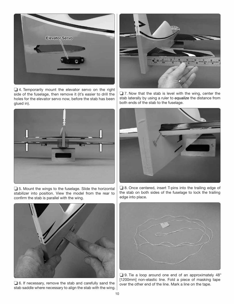
❏ 4. Temporarily mount the elevator servo on the right
side of the fuselage, then remove it (it’s easier to drill the
holes for the elevator servo now, before the stab has been
glued in).
❏ 5. Mount the wings to the fuselage. Slide the horizontal
stabilizer into position. View the model from the rear to
confi rm the stab is parallel with the wing.
❏ 6. If necessary, remove the stab and carefully sand the
stab saddle where necessary to align the stab with the wing.
❏ 7. Now that the stab is level with the wing, center the
stab laterally by using a ruler to equalize the distance from
both ends of the stab to the fuselage.
❏ 8. Once centered, insert T-pins into the trailing edge of
the stab on both sides of the fuselage to lock the trailing
edge into place.
❏ 9. Tie a loop around one end of an approximately 48"
[1200mm] non-elastic line. Fold a piece of masking tape
over the other end of the line. Mark a line on the tape.

11
❏ 10. Insert a pin into the middle of the fuselage crutch
across the top of the former as shown. Loop the line over
the pin.
❏ 11. Hold the line with the tape to one corner of the stab.
Swing the line over to the corner on the other end of the
stab. Adjust the stab and slide the tape along the line until
the stab is centered and equalized.
❏ 12. Once you’re satisfi ed with stab alignment, use a
fi ne-point felt-tip pen to mark the outline of the fuselage all
the way around both sides of the horizontal stabilizer. Even
though the ink and most of the covering on top of the stab
are black, you’ll still be able to see the line indicating where
the covering will be cut and removed in the next step.
❏ 13. Cut the covering 1/32" [1mm] inside the lines you
marked around the stab. A hobby knife may be used if
the blade is brand new and sharp so little pressure will be
required for cutting, but extreme care must be used to cut
only through the covering and not into the sheeting
otherwise, the stab will be weakened. The best way is with
a soldering iron with a cutting-type of tip. A heat setting of
about 500F [260C] seems to work well.
❏ 14. Wipe away any residual ink with a paper towel square
dampened with denatured alcohol, then peel the covering
from the stab.

12
Glue in the Horizontal Stabilizer
❏ 1. Gather your small paper towel squares and denatured
alcohol for epoxy clean up. Small balsa sticks chopped
up from 1/16" [1.5mm] balsa sheet are also handy for
“squeegeeing” away most of the epoxy before using the
paper towel squares.
❏ 2. Don’t forget to place the elevator joiner wire into the
fuselage. It can be held out of the way with a rubber band
as shown in following images.
CAUTION: Have everything ready and on-hand for gluing
in the stab. Work quickly and effi ciently because some
30-minute epoxies may harden faster than others and
time fl ies when trying to work with precision—you don’t
want the epoxy hardening up before you have the stab
accurately aligned. ❏ 3. Mix up approximately 1/4 oz. of 30-minute epoxy.
Apply epoxy all the way around the stab saddle on both
sides of the fuselage and to the top and bottom of the stab.
❏ 4. Slide the stab into position. Wipe away excess epoxy
with the balsa sticks and paper towel squares dampened
with denatured alcohol. Double-check alignment, place any
weight on the stab if required for alignment and allow the
epoxy to harden before proceeding.

13
Hinge the Elevators and Rudder
1. Once more, test-fi t the elevators to the stab with the joiner
wire and hinges to make certain all the hinges and the joiner
wire go in and everything fi ts together well.
❏ 2. Apply 30-minute epoxy into the groove and in the holes
for the joiner wire in the elevators. Wipe away excess epoxy.
❏ 3. Apply epoxy to the joiner wire. Then, fi t the elevators
to the stab and joiner wire with the hinges – use the T-pins if
necessary to keep the hinges centered.
❏ 4. Use a thin, metal ruler or similar tool to push the joiner
wire all the way into the elevators.
❏ 5. Permanently glue in the hinges with four or fi ve drops
of thin CA on the top and bottom of all the hinges – allow
a few seconds between drops for the CA to fully wick into
the hinges.
❏ 6. Retrieve the 50mm threaded rod, two wood washers,
two M2 washers, two M2 nuts, and two torque rod horns for
the rudder torque rod.
❏ 7. Cut a small circle of covering from both sides of the
rudder around the hole for the torque rod.

14
❏ 8. Use 30-minute epoxy to permanently glue the torque
rod centered into the rudder with the wood washers, metal
washers and M2 nuts as shown.
❏ 9. Thread the torque rod horns onto the rudder torque
rod so they are equidistant from the hinge line, then fi t the
rudder to the vertical stabilizer/fuselage with the hinges and
permanently glue them in.
Hook up the Rudder and Elevators
❏ 1. Cut the included rudder pull/pull line into two equal
lengths.
❏ 2. Loop one of the lines through the torque rod horn two
or three times. (It may be easier to push the line through if
you fi rst wet the end with thin CA.)
❏ 3. Install a brass cable swage over both ends of the
line. Position the swage about 1" [25mm] from the torque
rod horn.
❏ 4. Tighten the loops and squeeze the tube with pliers.

15
❏ 5. Cut off the short end of the line near the swage.
6. Guide the line through the slot and down through the
fuselage.
7. Attach the other line to the horn on the other side of the
rudder the same way.
❏ 8. Tape both sides of the rudder to hold it centered with
the fuselage.
❏ 9. Thread two brass couplers onto two clevises ten full
turns and install a silicone retainer.
10. Mount the rudder servo in the servo tray in the fuselage.
Rudder lines cross one time.S
3171S
V
❏ 11. Arrange the rudder pull-pull lines so they will cross as
illustrated. Also be sure the lines are below the cross brace
at the cockpit former as illustrated in the image at step 13.
❏ 12. With the servo arm and one of the clevises connected
to the servo and the servo powered and centered with the
radio on, attach the other end of one of the lines to the
threaded coupler as shown with another swage – use
hemostats or pliers to lightly tension the line while positioning
and squeezing the swage with pliers.
❏ 13. Attach the other rudder pull-pull line the same way.
❏ 14. Remove the tape that was holding the rudder
centered. Adjust the clevises on the couplers to add or
remove tension from the lines to center the rudder—the
lines should be tensioned just enough to keep the rudder
from fl opping around when the servo is powered.

16
❏ 15. Attach a 12" [305mm] servo extension to the elevator
servo, then mount the servo in the fuselage and guide the
wire down through into the cabin. Hook up the elevator
servo with the same hardware used for the ailerons with
one exception; if 3D throws are to be used, instead of
using a 90° pushrod connector on the servo, a Z-bend will
be required. If 3D throws are not going to be used a 90°
pushrod connector is fi ne.
Mount the Motor and ESC
❏ 1. Push a pin or a small nail into the four “+” marks in
the fi rewall, noting the location of the holes for the motor
mounting screws. If using a motor different than the
recommended RimFire .32, use the cross marks and the
circle on the fi rewall to align your motor and mark new holes.
❏ 2. Drill 1/16" [1.6mm] pilot holes through the punch
marks, then enlarge the holes with a 5/32" [4mm] drill.
❏ 3. Assemble, then mount the motor with four M3 x 10
Phillips screws, M3 lock washers and fl at washers and M3
blind nuts in the back of the fi rewall.
❏ 4. Prepare the ESC with any bullet connectors and
battery connectors needed. Then, mount the ESC to the
bottom of the motor mount box as shown with 1/8" [3.2mm]
double-side adhesive-backed foam mounting tape (or other
cushioning) and a nylon zip tie (not included).

17
❏ 5. Apply a full strip of the rougher, “hook” side of
adhesive-back hook-and-loop material to the battery tray
and a smaller, partial strip of the softer, “loop” side to your
battery. (The “loop” on the battery grips the “hook” on the
battery tray well, potentially making battery removal diffi cult,
so only a small strip is needed on the battery. And it’s the
hook-and-loop strap that does most of the work securing
the battery anyway.)
❏ 6. Make a battery strap from the non-adhesive-back hook-
and-loop strip.
Final Radio Installation
Refer to this image while mounting the receiver.
1. Connect the ESC and elevator and rudder servos to the
receiver and 6" [150mm] servo extensions for the aileron
servos. Mount the receiver with adhesive-back hook-and-
loop strips or other preferred method. Guide the servo wires
over and around the internal structure as needed so nothing
interferes with the rudder pull/pull lines.
2. Position and secure the receiver antennas according to the
receiver manufacturer’s specifi cations. For the Futaba receiver
shown (and Tactic), the antennas are to be positioned 90° to
each other. Small pieces of plastic tubing (as from an aerosol
spray can or similar) were glued to the fuselage in the desired
location and the antennas were inserted into the tubes.
3. Without the propeller, make a quick test-run of the motor
to make sure it is turning in the correct direction. If necessary,
swap any two of the three motor wires that connect to the
ESC, or reverse the motor direction in your ESC.
FINAL ASSEMBLY
Mount the Landing Gear
1/8"[3mm]
3/16"[5mm]
Wheel Axle
Flat spot
❏ 1. File a 3/16" [5mm] fl at spot on the wheel axle 1/8"
[3mm] from the end.

18
Axle
Washer
Nut
Wheel
Collar
Wheel pant
❏ 2. Assemble the wheel and wheel pant to the landing
gear as shown—hold the nut with hemostats or needle-nose
pliers while tightening the axle with a fl at-blade screwdriver.
Tighten the set screw with a 1/16" hex driver wrench.
3. Assemble the other gear/wheel/pant assembly the same
way.
❏ 4. Mount the main landing gear to the fuselage with four
M3 x 10 SHCS and lock washers and fl at washers.
❏ 5. Glue the nylon tail gear bushing into the bottom of the
fuselage.
❏ 6. Slide the tail gear clip and a small wheel collar over the
tail gear wire, then insert the assembly down into the
bushing. Align the clip, swing the tail gear out of the way,
then drill 1/16" [1.6mm] holes through the bottom of the
fuselage for the mounting screws.
❏ 7. Use medium-
grit sandpaper to
roughen the end of
the axle portion of the
tail gear wire so glue
will adhere. Install the
tail wheel, add a small
drop of medium CA to
the very end of the wire,
and then press a nylon
retainer onto the wire to
retain the wheel. Add
another drop of thin CA
to the retainer around
the wire.

19
❏ 8. Mount the tail gear wire with the clip, two M2 x 10
Phillips wood screws and a wheel collar with the set screw.
Use a .050" hex driver wrench to tighten the set screw to
lock-in the tail gear wire, then slip the nylon tiller peg over
the tiller wire on the end of the tail gear and fi t, then glue the
peg into the bottom of the rudder.
Mount the Cowl
❏ 1. Cut four approximately 4" [100mm] long “fi ngers” from
paper or thin cardstock. Use a 3/32" [2.4mm] brass tube
sharpened on the end or a hobby knife to cut a small hole in
the end of each fi nger.
❏ 2. Align the hole in each fi nger with the hole in each tab
for the cowl mounting screws and securely tape the fi ngers
to the fuselage.
❏ 3. Install the cowl, the spinner back plate, propeller and
prop nut to the motor. Position the cowl so it accurately
aligns with the spinner back plate with the desired spinner
gap (approximately 3/32" [2.5mm]). If necessary, use tape or
an assistant to hold the cowl in alignment while marking the
holes in the fi ngers onto the cowl. (Once aligned, the cowl
on our model stayed in place on its own.)
❏ 4. Remove the prop, spinner and cowl. Support the
inside of the cowl with a piece of wood while drilling 1/16"
[1.6mm] pilot holes through the cowl at the marks you made.
❏ 5. Enlarge the pilot holes with a 1/8" [3.2 mm] drill. Then,
test-mount the cowl with the spinner and prop using M3 x 10
Phillips screws and lock washers and fl at washers. The 1/8"
holes in the cowl should be just large enough to fi t the screws,
so if the cowl requires slight adjusting to perfectly align with

20
the spinner, the screw holes may be enlarged or elongated to
slightly reposition the cowl.
6. Remove the propeller and spinner for checking the
control throws next.
PREPARE THE MODEL FOR FLIGHT
Set the Control Throws
CAUTION: The propeller should not be installed. If
you have not yet done so, remove the propeller before
checking the control throws on the workbench.
❏ 1. It is easiest to check and set the aileron throws with the
wing mounted to the fuselage. Install the wing and connect
the aileron servos to the receiver.
❏ 2. Support the fuselage so the model will sit level, or nearly
level. Use a ruler (or a tool that measures angular degrees)
to measure and set the control throws according to the
measurements below. NOTE: The control throws are measured
at the widest part of each surface and the dimensions
provided are for each direction of travel. (Example: low-rate
aileron throw is 3/8" [9mm] up and 3/8" [9mm] down.)
CONTROL SURFACE THROWS (each direction)
AILERONS
RUDDER
ELEVATORS
LOW RATE
3/8"
[9mm]
Up & Down
7/16"
[11mm]
Up & Down
1"
[25mm]
Right & Left
HIGH RATE
3/4"
[19mm]
Up & Down
3/4"
[19mm]
Up & Down
1-3/4"
[45 mm]
Right & Left
3D
1-7/8"
[48 mm]
Up & Down
2"
[51mm]
Up & Down
2-3/4"
[ 70mm]
Right & Left
❏ 3. Use the programming in your transmitter and/or move
the pushrods to holes farther out or in on your servo arms
and/or the control horns to adjust the control throws as
necessary.
❏ 4. If using the 3D throws, a high volume of negative
exponential is desirable on 3D rates – approximately -60%
is a good place to start for each surface.
❏ 5. While working with radio setup and programming
(and before installing the propeller), now would be a
good time to set and check the Failsafe function so
that, in the event the receiver ever loses signal (such
as if you inadvertently turn off the transmitter before
disconnecting the battery) the throttle will go to a pre-set
position. The recommended pre-set throttle position is
“off”, so the motor will not turn. Follow the instructions
that came with your radio control system to check and
set the failsafe.
Check the C.G.
❏ 1. If you haven’t yet done so, get the model in completely
ready-to-fl y condition. First install the propeller and spinner
with a sandpaper disc on both sides of the spinner back
plate. The sandpaper discs allow the back plate to grip the
motor and propeller so it will not rotate while tightening the
propeller nut.

21
❏ 2. Install the battery but do not connect it. Attach the
wings with the M3 x 10 SHCS screws, lock washers and fl at
washers used before, then install the canopy hatch.
3-1/4"83mm
The recommended C.G. is 3-1/4" [83mm] back from
the leading edge of the wing where it meets the
fuselage. The recommended C.G. range is from
2-3/4" – 3-3/4" [70mm - 95mm].
❏ 2. Use a Great Planes C.G. Machine with the rulers set to
the recommended C.G. and place the model upside-down
on the stand, or mark the recommended C.G. on top of the
wing and lift the model upside-down with your fi ngertips.
3. Shift the battery forward or aft or add nose or tail weight
as necessary to get the model to balance.
Balance the Model Laterally
❏ 1. Support the bottom of the rudder (a servo case was
used for the model in the image) and lift the Sbach several
times by the propeller shaft to see if one wing drops. Do this
several times to get a consistent reading.
❏ 2. If one wing drops consistently, add weight to the
opposite tip by sticking it to the outside or strategically
concealing it inside the balsa tip. An airplane that has been
laterally balanced will track better in fl ight and maintain its
heading better during maneuvers when the plane is climbing.
❏ 3. This static lateral balance check will be a good starting
point, but performance in the air will be the fi nal determining
factor whether or not the model is laterally balanced.
Performing high-G pulls will reveal if further lateral balance
is required. Adjust the weight as necessary.
PREFLIGHT
Motor Safety Precautions
Failure to follow these safety precautions may result
in severe injury to yourself and others.
● Use safety glasses when running motors.
● Do not run the motor in an area of loose gravel or sand;
the propeller may throw such material in your face or eyes.
● Keep your face and body as well as all spectators away
from the plane of rotation of the propeller when the motor
is running.
● Keep these items away from the prop: loose clothing,
shirt sleeves, ties, scarfs, long hair or loose objects such
as pencils or screwdrivers that may fall out of shirt or
jacket pockets into the prop.

22
WARNING: Never have the motor battery connected
to the ESC without the transmitter turned on – after
each fl ight (or any time after running the motor) always
disconnect the battery before turning off the transmitter.
And when ready to fl y (or whenever running the motor
for any reason), always turn on the transmitter fi rst
before connecting the motor battery.
Also make certain your failsafe is activated and programmed
correctly according to your radio manufacturer’s instructions.
Motor/Propeller Discussion
The recommended Rimfi re .32 is rated for 50A constant
current and 80A surge current. Powered by a 4S LiPo on
an APC 13 x 8E it draws about 58A static and momentary,
maximum peaks of about 50 – 55A in the air, but averages
a little less than 20A through a “normal” fl ight. This is a
suitable propeller choice and fl ies the Sbach well. Another
suitable propeller choice is the APC or Xoar 14 x 7 which
provides slightly more thrust at the expense of a little speed
which is okay for this type of plane. You can experiment
with different propeller choices in this range as long as
they do not exceed the current specifi cations of the motor
and ESC.
Typical fl ight time may be as low as 4 minutes or over 8
minutes depending on how aggressive and active you are
with the throttle – more throttle means shorter fl ight times.
Use a fl ight timer initially set to a conservative time (4
minutes for example). When the timer sounds, land. Use
a LiPo checker (shown above) to measure the resting
(unloaded) voltage when you land. The voltage should not
be below 3.75V/cell. When you charge the battery also
note how much capacity it took to recharge (indicating how
much was used for the fl ight). Aim to use no more than 80%
of the battery’s capacity. Adjust your timer according to the
voltage and capacity used for the fl ight.
You can also use the worksheet on page 24 to determine
optimum fl ight times based on your fl ying style and
battery capacity.
CAUTION: Never run the motor on the ground for more
than a few seconds. Otherwise, you may overload the
motor, battery or ESC.
Battery Precautions
Charge and store LiPo batteries in a safe place!
Never leave charging LiPo batteries unattended!
Before mounting the motor and setting up the ESC
and battery, read the following important battery
precautions:
IMPORTANT: If using multiple battery packs that are
connected with an adapter, never charge the batteries
together through the adapter. Always charge each
battery pack separately. Charge the batteries, then
read the following precautions on how to connect
multiple packs for fl ying the model:
Battery Precautions:
There are two ways to connect multiple battery packs: In Series and in Parallel.

23
This is a SERIES battery adapter
that connects two batteries in series.
(3-Cell) 3200 mAh
(2-Cell) 3200 mAh
11.1V
7.4V
These are two 3200mAh batteries (one 11.1V and the
other 7.4V). When joined in SERIES, the result will be a
18.5V, 3200 mAh battery.
1. Connecting batteries in “Series” means to connect the +’s to the –’s and the –’s to the +’s. This combines the batteries’ Voltages, but the capacity remains the same.
This is a PARALLEL battery adapter that
connects two batteries in parallel.
(3-Cell) 1500 mAh
(3-Cell) 1500 mAh
11.1V
11.1V
These two 1500mAh batteries (both 11.1V) are being
joined in PARALLEL. The result will be one 11.1V, 3000mAh battery.
2. Connecting batteries in “Parallel” means to connect the +’s to the +’s and the -’s to the -’s. This combines the batteries’ capacities, but the Voltage remains the same.
PARALLELadapter
(2-Cell)
(3-Cell)
11.1V
7.4V
PARALLELter
(3
NEVER connect battery packs with different Voltages in Parallel–only combine in Series. Otherwise, the batteries will try to “equalize” with the larger one trying to “charge” the smaller one, thus causing heat and likely a fi re.
(3-Cell) 3200mAh
11.1V
(3-Cell) 1250mAh
11.1V
SERIESadapter
Ah
SERIESter
Also NEVER connect battery packs with different ca-pacities in Series or in Parallel.
Range Check
Don’t forget to perform your usual ground range checks as
written in the instruction manual that came with your radio
system to be certain it is operating correctly.
AMA SAFETY CODE (excerpts)
Read and abide by the following excerpts from the Academy
of Model Aeronautics Safety Code. For the complete Safety
Code refer to Model Aviation magazine, the AMA web site
or the Code that came with your AMA license.
General
1) I will not fl y my model aircraft in sanctioned events, air shows,
or model fl ying demonstrations until it has been proven to be
airworthy by having been previously, successfully fl ight tested.
2) I will not fl y my model aircraft higher than approximately
400 feet within 3 miles of an airport without notifying the
airport operator. I will give right-of-way and avoid fl ying
in the proximity of full-scale aircraft. Where necessary, an
observer shall be utilized to supervise fl ying to avoid having
models fl y in the proximity of full-scale aircraft.
3) Where established, I will abide by the safety rules for the
fl ying site I use, and I will not willfully and deliberately fl y my
models in a careless, reckless and/or dangerous manner.
5) I will not fl y my model unless it is identifi ed with my name
and address or AMA number, on or in the model. Note: This
does not apply to models while being fl own indoors.
7) I will not operate models with pyrotechnics (any device
that explodes, burns, or propels a projectile of any kind).
Radio Control
1) I will have completed a successful radio equipment ground
check before the fi rst fl ight of a new or repaired model.

TOWA2026 v2© 2018 Tower Hobbies.® A subsidiary of Hobbico, Inc.
2) I will not fl y my model aircraft in the presence of
spectators until I become a qualifi ed fl ier, unless assisted
by an experienced helper.
3) At all fl ying sites a straight or curved line(s) must be
established in front of which all fl ying takes place with the
other side for spectators. Only personnel involved with
fl ying the aircraft are allowed at or in the front of the fl ight
line. Intentional fl ying behind the fl ight line is prohibited.
4) I will operate my model using only radio control frequencies
currently allowed by the Federal Communications
Commission.
5) I will not knowingly operate my model within three miles
of any pre-existing fl ying site except in accordance with the
frequency sharing agreement listed [in the complete AMA
Safety Code].
9) Under no circumstances may a pilot or other person
touch a powered model in fl ight; nor should any part of the
model other than the landing gear, intentionally touch
the ground, except while landing.
FLYING
The Sbach has no bad fl ight characteristics or idiosyncrasies
that you need to be made aware of ahead of time. The C.G.
and control throws specifi ed in this manual will provide
you with a predictable, easy-fl ying sport model. The Sbach
ground-handles well, but for taxiing around to maneuver in
the pits and out to the runway/takeoff zone you’ll want high-
rate or 3D-rate rudder. High-rate or 3D-rate elevator may
also assist when holding “up” elevator to keep the tail on
the ground if taxiing on grass. But for the maiden takeoff,
low rates are recommended. The Sbach exhibits little roll
and pitch coupling with rudder input, but for a reduced
work load and for perfection you may eventually want to
program in an elevator and aileron mix to rudder so that any
undesired coupling can be mixed out.
Have a ball! But always stay in control and fl y in a safe manner.
GOOD LUCK AND GREAT FLYING!
Use this chart to calculate the recommended fl ight time.
FORMULASA
123456789
10
B C D E F GB / A D x .8 E / C B/1000 / (A/60)
Flight Time
(.10 ths )
Recharge
CapacitymAh/minute
Battery
Capacity
Target Capacity
to Use in Flight
Recommended
Flight Time
Avg. In-Flight
Current