Embed Size (px)
Citation preview
YOU'RE HEARD, LOUD AND CLEAR.
8625 Industrial Parkway, Angola, NY 14006 Tel: 716-549-4700 Fax: 716-549-4772 [email protected] www.bird-technologies.com
Instruction ManualVari-Notch® Cavity Filter6 5/8” and 10” Diameter
Manual Part Number
7-9144
Warranty
This warranty applies for one year from shipping date.
TX RX Systems Inc. warrants its products to be free from defect in material and workmanship at the time of shipment.Our obligation under warranty is limited to replacement or repair, at our option, of any such products that shall havebeen defective at the time of manufacture. TX RX Systems Inc. reserves the right to replace with merchandise ofequal performance although not identical in every way to that originally sold. TX RX Systems Inc. is not liable for dam-age caused by lightning or other natural disasters. No product will be accepted for repair or replacement without ourprior written approval. The purchaser must prepay all shipping charges on returned products. TX RX Systems Inc.shall in no event be liable for consequential damages, installation costs or expense of any nature resulting from thepurchase or use of products, whether or not they are used in accordance with instructions. This warranty is in lieu of allother warranties, either expressed or implied, including any implied warranty or merchantability of fitness. No repre-sentative is authorized to assume for TX RX Systems Inc. any other liability or warranty than set forth above in con-nection with our products or services.
TERMS AND CONDITIONS OF SALE PRICES AND TERMS:Prices are FOB seller’s plant in Angola, NY domestic packaging only, and are subject to change without notice. Fed-eral, State and local sales or excise taxes are not included in prices. When Net 30 terms are applicable, payment isdue within 30 days of invoice date. All orders are subject to a $100.00 net minimum.
QUOTATIONS:Only written quotations are valid.
ACCEPTANCE OF ORDERS:Acceptance of orders is valid only when so acknowledged in writing by the seller.
SHIPPING:Unless otherwise agreed at the time the order is placed, seller reserves the right to make partial shipments for whichpayment shall be made in accordance with seller’s stated terms. Shipments are made with transportation charges col-lect unless otherwise specified by the buyer. Seller’s best judgement will be used in routing, except that buyer’s routingis used where practicable. The seller is not responsible for selection of most economical or timeliest routing.
CLAIMS:All claims for damage or loss in transit must be made promptly by the buyer against the carrier. All claims for shortagesmust be made within 30 days after date of shipment of material from the seller’s plant.
SPECIFICATION CHANGES OR MODIFICATIONS:All designs and specifications of seller’s products are subject to change without notice provided the changes or modifi-cations do not affect performance.
RETURN MATERIAL:Product or material may be returned for credit only after written authorization from the seller, as to which seller shallhave sole discretion. In the event of such authorization, credit given shall not exceed 80 percent of the original pur-chase. In no case will Seller authorize return of material more than 90 days after shipment from Seller’s plant. Creditfor returned material is issued by the Seller only to the original purchaser.
ORDER CANCELLATION OR ALTERATION:Cancellation or alteration of acknowledged orders by the buyer will be accepted only on terms that protect the selleragainst loss.
NON WARRANTY REPAIRS AND RETURN WORK:Consult seller’s plant for pricing. Buyer must prepay all transportation charges to seller’s plant. Standard shipping pol-icy set forth above shall apply with respect to return shipment from TX RX Systems Inc. to buyer.
DISCLAIMER Product part numbering in photographs and drawings is accurate at time of printing. Part number labels on TX RXproducts supersede part numbers given within this manual. Information is subject to change without notice.
Bird Technologies Group TX RX Systems Inc.
Symbols Commonly Used
NOTE
ESD Elecrostatic Discharge
Hot Surface
Electrical Shock Hazard
Important Information
CAUTION or ATTENTION
High Voltage
Use Safety Glasses
WARNING
Bird Technologies Group TX RX Systems Inc.
Manual Part Number 7-9144Copyright © 1996 TX RX Systems, Inc.
First Printing: July 1996
Version Number Version Date
1 07/22/96

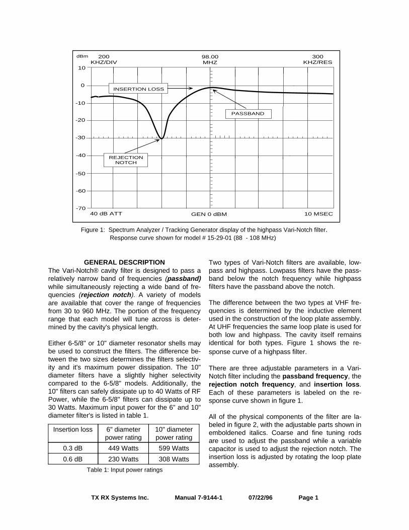
GENERAL DESCRIPTION
The Vari-Notch® cavity filter is designed to pass arelatively narrow band of frequencies (passband)while simultaneously rejecting a wide band of fre-quencies (rejection notch ). A variety of modelsare available that cover the range of frequenciesfrom 30 to 960 MHz. The portion of the frequencyrange that each model will tune across is deter-mined by the cavity's physical length.
Either 6-5/8" or 10" diameter resonator shells maybe used to construct the filters. The difference be-tween the two sizes determines the filters selectiv-ity and it's maximum power dissipation. The 10"diameter filters have a slightly higher selectivitycompared to the 6-5/8" models. Additionally, the10" filters can safely dissipate up to 40 Watts of RFPower, while the 6-5/8" filters can dissipate up to30 Watts. Maximum input power for the 6" and 10"diameter filter's is listed in table 1.
Two types of Vari-Notch filters are available, low-pass and highpass. Lowpass filters have the pass-band below the notch frequency while highpassfilters have the passband above the notch.
The difference between the two types at VHF fre-quencies is determined by the inductive elementused in the construction of the loop plate assembly.At UHF frequencies the same loop plate is used forboth low and highpass. The cavity itself remainsidentical for both types. Figure 1 shows the re-sponse curve of a highpass filter.
There are three adjustable parameters in a Vari-Notch filter including the passband frequency , therejection notch frequency , and insertion loss .Each of these parameters is labeled on the re-sponse curve shown in figure 1.
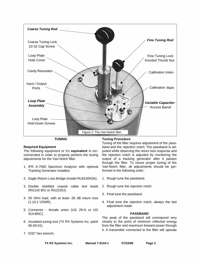
All of the physical components of the filter are la-beled in figure 2, with the adjustable parts shown inemboldened italics. Coarse and fine tuning rodsare used to adjust the passband while a variablecapacitor is used to adjust the rejection notch. Theinsertion loss is adjusted by rotating the loop plateassembly.
TX RX Systems Inc. Manual 7-9144-1 07/22/96 Page 1
dBm
REJECTIONNOTCH
INSERTION LOSS
PASSBAND
0
10
-10
-20
-30
-40
-50
-60
-70
200KHZ/DIV
98.00MHZ
300KHZ/RES
10 MSECGEN 0 dBM40 dB ATT
Figure 1: Spectrum Analyzer / Tracking Generator display of the highpass Vari-Notch filter. Response curve shown for model # 15-29-01 (88 - 108 MHz)
Insertion loss 6" diameterpower rating
10" diameterpower rating
0.3 dB 449 Watts 599 Watts
0.6 dB 230 Watts 308 Watts
Table 1: Input power ratings
TUNING
Required EquipmentThe following equipment or it's equivalent is rec-ommended in order to properly perform the tuningadjustments for the Vari-Notch filter.
1. IFR A-7550 Spectrum Analyzer with optionalTracking Generator installed.
2. Eagle Return Loss Bridge (model RLB150N3A).
3. Double shielded coaxial cable test leads(RG142 B/U or RG223/U).
4. 50 Ohm load, with at least -35 dB return loss(1.10:1 VSWR).
5. Connector - female union (UG 29-N or UG914-BNC).
6. Insulated tuning tool (TX RX Systems Inc. part#95-00-01).
7. 5/32" hex wrench.
Tuning ProcedureTuning of the filter requires adjustment of the pass-band and the rejection notch. The passband is ad-justed while observing the return loss response andthe rejection notch is adjusted by monitoring theoutput of a tracking generator after it passesthrough the filter. To insure proper tuning of theVari-Notch filter, all adjustments should be per-formed in the following order:
1. Rough tune the passband.
2. Rough tune the rejection notch.
3. Final tune the passband.
4. Final tune the rejection notch, always the lastadjustment made.
PASSBANDThe peak of the passband will correspond veryclosely to the point of minimum reflected energyfrom the filter and maximum forward power throughit. A transmitter connected to the filter will operate
TX RX Systems Inc. Manual 7-9144-1 07/22/96 Page 2
Coarse Tuning Rod
Coarse Tuning Lock
Calibration Index
Calibration
Loop PlateHold Down Screws
Input / Output
Fine Tuning Rod
Cavity Resonator
Fine Tuning LockKnurled Thumb Nut
Loop PlateAssembly
Variable CapacitorAccess Barrel
Ports
Loop PlateHole Cover
Mark
10-32 Cap Screw
Figure 2: The Vari-Notch filter.
best when the reflected energy is lowest, thereforethe return loss response will be used to set thepassband. The passband can be checked and ad-justed using the following procedure.
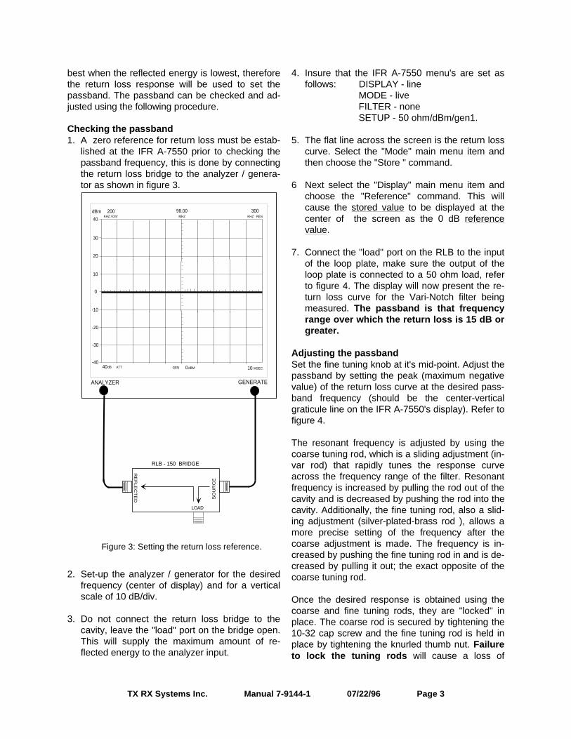
Checking the passband 1. A zero reference for return loss must be estab-
lished at the IFR A-7550 prior to checking thepassband frequency, this is done by connectingthe return loss bridge to the analyzer / genera-tor as shown in figure 3.
2. Set-up the analyzer / generator for the desiredfrequency (center of display) and for a verticalscale of 10 dB/div.
3. Do not connect the return loss bridge to thecavity, leave the "load" port on the bridge open.This will supply the maximum amount of re-flected energy to the analyzer input.
4. Insure that the IFR A-7550 menu's are set asfollows: DISPLAY - line
MODE - liveFILTER - noneSETUP - 50 ohm/dBm/gen1.
5. The flat line across the screen is the return losscurve. Select the "Mode" main menu item andthen choose the "Store " command.
6 Next select the "Display" main menu item andchoose the "Reference" command. This willcause the stored value to be displayed at thecenter of the screen as the 0 dB referencevalue.
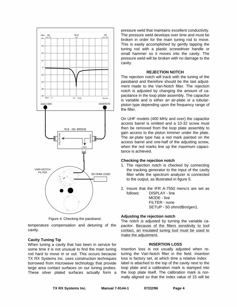
7. Connect the "load" port on the RLB to the inputof the loop plate, make sure the output of theloop plate is connected to a 50 ohm load, referto figure 4. The display will now present the re-turn loss curve for the Vari-Notch filter beingmeasured. The passband is that frequencyrange over which the return loss is 15 dB orgreater.
Adjusting the passbandSet the fine tuning knob at it's mid-point. Adjust thepassband by setting the peak (maximum negativevalue) of the return loss curve at the desired pass-band frequency (should be the center-verticalgraticule line on the IFR A-7550's display). Refer tofigure 4.
The resonant frequency is adjusted by using thecoarse tuning rod, which is a sliding adjustment (in-var rod) that rapidly tunes the response curveacross the frequency range of the filter. Resonantfrequency is increased by pulling the rod out of thecavity and is decreased by pushing the rod into thecavity. Additionally, the fine tuning rod, also a slid-ing adjustment (silver-plated-brass rod ), allows amore precise setting of the frequency after thecoarse adjustment is made. The frequency is in-creased by pushing the fine tuning rod in and is de-creased by pulling it out; the exact opposite of thecoarse tuning rod.
Once the desired response is obtained using thecoarse and fine tuning rods, they are "locked" inplace. The coarse rod is secured by tightening the10-32 cap screw and the fine tuning rod is held inplace by tightening the knurled thumb nut. Failureto lock the tuning rods will cause a loss of
TX RX Systems Inc. Manual 7-9144-1 07/22/96 Page 3
0
10
-10
-20
-30
-40
20
30
40
200KHZ / DIV MHZ
98.00 300KHZ RES
dBm
40dB ATT GEN dBM0 10 MSEC
ANALYZER GENERATE
RLB - 150 BRIDGE
LOAD
RE
FLE
CT
ED S
OU
RC
E
Figure 3: Setting the return loss reference.
temperature compensation and detuning of thecavity.
Cavity Tuning TipWhen tuning a cavity that has been in service forsome time it is not unusual to find the main tuningrod hard to move in or out. This occurs becauseTX RX Systems Inc. uses construction techniquesborrowed from microwave technology that providelarge area contact surfaces on our tuning probes.These silver plated surfaces actually form a
pressure weld that maintains excellent conductivity.The pressure weld develops over time and must bebroken in order for the main tuning rod to move.This is easily accomplished by gently tapping thetuning rod with a plastic screwdriver handle orsmall hammer so it moves into the cavity. Thepressure weld will be broken with no damage to thecavity.
REJECTION NOTCHThe rejection notch will track with the tuning of thepassband and therefore should be the last adjust-ment made to the Vari-Notch filter. The rejectionnotch is adjusted by changing the amount of ca-pacitance in the loop plate assembly. The capacitoris variable and is either an air-plate or a tubular-piston type depending upon the frequency range ofthe filter.
On UHF models (400 MHz and over) the capacitoraccess barrel is omitted and a 10-32 screw mustthen be removed from the loop plate assembly togain access to the piston trimmer under the plate.The air-plate type has a red mark painted on theaccess barrel and one-half of the adjusting screw,when the red marks line up the maximum capaci-tance is achieved.
Checking the rejection notch1. The rejection notch is checked by connecting
the tracking generator to the input of the cavityfilter while the spectrum analyzer is connectedto the output, as illustrated in figure 5.
2. Insure that the IFR A-7550 menu's are set asfollows: DISPLAY - line
MODE - liveFILTER - noneSETUP - 50 ohm/dBm/gen1.
Adjusting the rejection notchThe notch is adjusted by turning the variable ca-pacitor. Because of the filters sensitivity to toolcontact, an insulated tuning tool must be used tomake the adjustment.
INSERTION LOSSInsertion loss is not usually adjusted when re-tuning the Vari-Notch filter in the field. Insertionloss is factory set, at which time a relative index label is attached to the top of the cavity next to theloop plate and a calibration mark is stamped intothe loop plate itself. The calibration mark is nor-mally aligned so that the index value of 15 will be
TX RX Systems Inc. Manual 7-9144-1 07/22/96 Page 4
0
10
-10
-20
-30
-40
20
30
40
200KHZ / DIV MHZ
98.00 300KHZ RES
dBm
40dB ATT GEN dBM0 10 MSEC
ANALYZER GENERATE
RLB - 150 BRIDGE
LOAD
RE
FLE
CT
ED S
OU
RC
E
50 OHM LOAD
0
510
1520
VARI-NOTCHFILTER
Figure 4: Checking the passband.
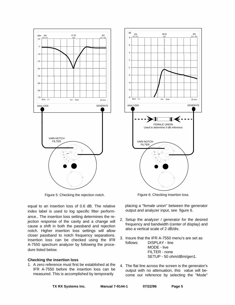
equal to an insertion loss of 0.6 dB. The relativeindex label is used to log specific filter perform-ance.. The insertion loss setting determines the re-jection response of the cavity and a change willcause a shift in both the passband and rejectionnotch. Higher insertion loss settings will allowcloser passband to notch frequency separations.Insertion loss can be checked using the IFRA-7550 spectrum analyzer by following the proce-dure listed below.
Checking the insertion loss1. A zero reference must first be established at the
IFR A-7550 before the insertion loss can bemeasured. This is accomplished by temporarily
placing a "female union" between the generatoroutput and analyzer input, see figure 6.
2. Setup the analyzer / generator for the desiredfrequency and bandwidth (center of display) andalso a vertical scale of 2 dB/div.
3. Insure that the IFR A-7550 menu's are set as
follows: DISPLAY - lineMODE - liveFILTER - noneSETUP - 50 ohm/dBm/gen1.
4. The flat line across the screen is the generator'soutput with no attenuation, this value will be-come our reference by selecting the "Mode"
TX RX Systems Inc. Manual 7-9144-1 07/22/96 Page 5
0
200KHZ / DIV MHZ
98.00 300KHZ RES
40dB ATT GEN dBM0 10 MSEC
ANALYZER GENERATE
VARI-NOTCHFILTER
0
510
1520
2
4
6
8
dB
-2
-4
-6
-8
FEMALE UNIONUsed to determine 0 dB reference
Figure 6: Checking insertion loss.
0
10
-10
-20
-30
-40
200KHZ / DIV MHZ
97.00 300KHZ RES
dBm
40dB ATT GEN dBM0 10 MSEC
ANALYZER GENERATE
VARI-NOTCHFILTER
0
5
1015
20
-50
-60
-70
Figure 5: Checking the rejection notch.
main menu item and choosing the "Store"command.
5. Next select the "Display" main menu item andchoose the "Reference" command. This willcause the stored value to be displayed at thecenter of the screen as the 0 dB referencevalue.
6. Connect the generator output and analyzer in-
put to the input/output ports of the loop plateand the amount of insertion loss offered by theVari-Notch filter will be displayed on the IFRA-7550's screen, refer to figure 6.
Adjusting the insertion lossAdjustments are made by loosening the three10-32 screws that hold the loop plate into positionand then rotating the plate itself. When the calibra-tion mark is pointed at the relative index setting of 15 the insertion loss will be 0.6 dB (calibrated byfactory).
Rotating the loop plate assembly and moving thecalibration mark above or below 15 causes the in-sertion loss to be increased or decreased (above15 increases the loss while below 15 decreases it).Insertion loss is adjustable across a useable rangeof from 0.3 dB to 1.0 dB.
MULTIPLE CAVITY VARI-NOTCH FILTERSVari-Notch filters can be ordered in multiple cavityarrangements of either two or three combined cavi-ties. In these arrangements, identical filters areconnected in a cascaded fashion with the output ofeach filter fed to the input port of the succeedingfilter. The advantage to this arrangement is that theamount of attenuation provided by each of the fil-ters is additive. In the case of the rejection notchfrequency, the dual cavity can provide attenuationof over 60 dB (30 dB for each filter).
Also, the interconnecting cable between the twofilters, when cut to the correct length (odd multipleof a 1/4 λ), will provide up to 6 dB of additional at-tenuation due to a mismatch of impedance be-tween the cable and the filters. The 6 dB ofmismatch attenuation does not occur at the filterspassband but, only at frequencies where moderateto high attenuation occurs, such as at the rejectionnotch frequency. Because each of the filters in themulti-cavity arrangement are identical, the pass-band for the entire arrangement is generally the
same as the passband for the individual filters.However, each filters individual insertion loss isalso additive. When tuning a multi-cavity arrange-ment, each filter is tuned individually prior to inter-connecting them. Then each is fine tuned to peakthe overall response of the multi-cavityarrangement.
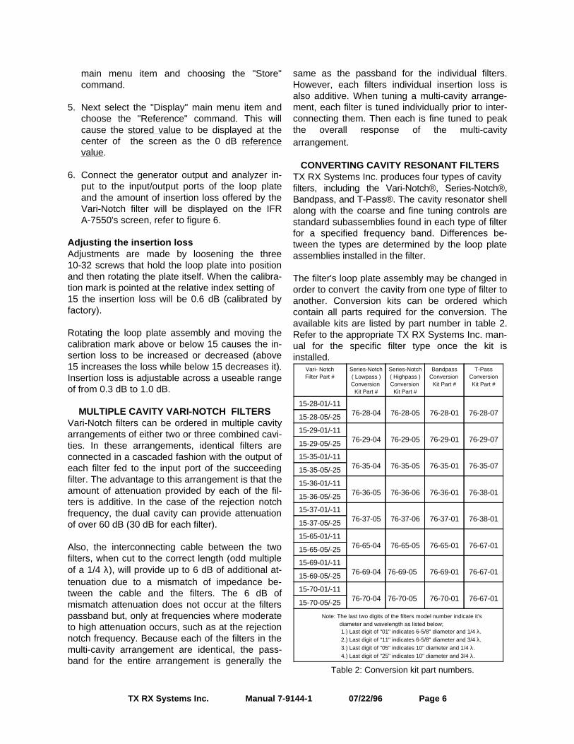
CONVERTING CAVITY RESONANT FILTERSTX RX Systems Inc. produces four types of cavity filters, including the Vari-Notch®, Series-Notch®,Bandpass, and T-Pass®. The cavity resonator shellalong with the coarse and fine tuning controls arestandard subassemblies found in each type of filterfor a specified frequency band. Differences be-tween the types are determined by the loop plateassemblies installed in the filter.
The filter's loop plate assembly may be changed inorder to convert the cavity from one type of filter toanother. Conversion kits can be ordered whichcontain all parts required for the conversion. Theavailable kits are listed by part number in table 2.Refer to the appropriate TX RX Systems Inc. man-ual for the specific filter type once the kit isinstalled.
TX RX Systems Inc. Manual 7-9144-1 07/22/96 Page 6
Vari- NotchFilter Part #
Series-Notch( Lowpass )Conversion
Kit Part #
Series-Notch( Highpass )Conversion
Kit Part #
BandpassConversion
Kit Part #
T-PassConversionKit Part #
15-28-01/-1176-28-04 76-28-05 76-28-01 76-28-0715-28-05/-25
15-29-01/-1176-29-04 76-29-05 76-29-01 76-29-0715-29-05/-25
15-35-01/-1176-35-04 76-35-05 76-35-01 76-35-0715-35-05/-25
15-36-01/-1176-36-05 76-36-06 76-36-01 76-38-0115-36-05/-25
15-37-01/-1176-37-05 76-37-06 76-37-01 76-38-0115-37-05/-25
15-65-01/-1176-65-04 76-65-05 76-65-01 76-67-0115-65-05/-25
15-69-01/-1176-69-04 76-69-05 76-69-01 76-67-0115-69-05/-25
15-70-01/-1176-70-04 76-70-05 76-70-01 76-67-0115-70-05/-25
Note: The last two digits of the filters model number indicate it's diameter and wavelength as listed below; 1.) Last digit of "01" indicates 6-5/8" diameter and 1/4 λ. 2.) Last digit of "11" indicates 6-5/8" diameter and 3/4 λ. 3.) Last digit of "05" indicates 10" diameter and 1/4 λ. 4.) Last digit of "25" indicates 10" diameter and 3/4 λ.
Table 2: Conversion kit part numbers.
Bird Technologies Group TX RX Systems Inc.
100
90
80
70
60
50
40
.2 .3 .4 .5 .6 .7 .8 .9 1 2 3 4 5 6 7 8 9 10
132 - 174 MHz Band
Att
enu
atio
n
Frequency Separation (MHz)
.2 .3 .4 .5 .6 .7 .8 .9 1 2 3 4 5 6 7 8 9 10Frequency Separation (MHz)
100
90
80
70
60
50
40
400 - 512 MHz Band
Att
enu
atio
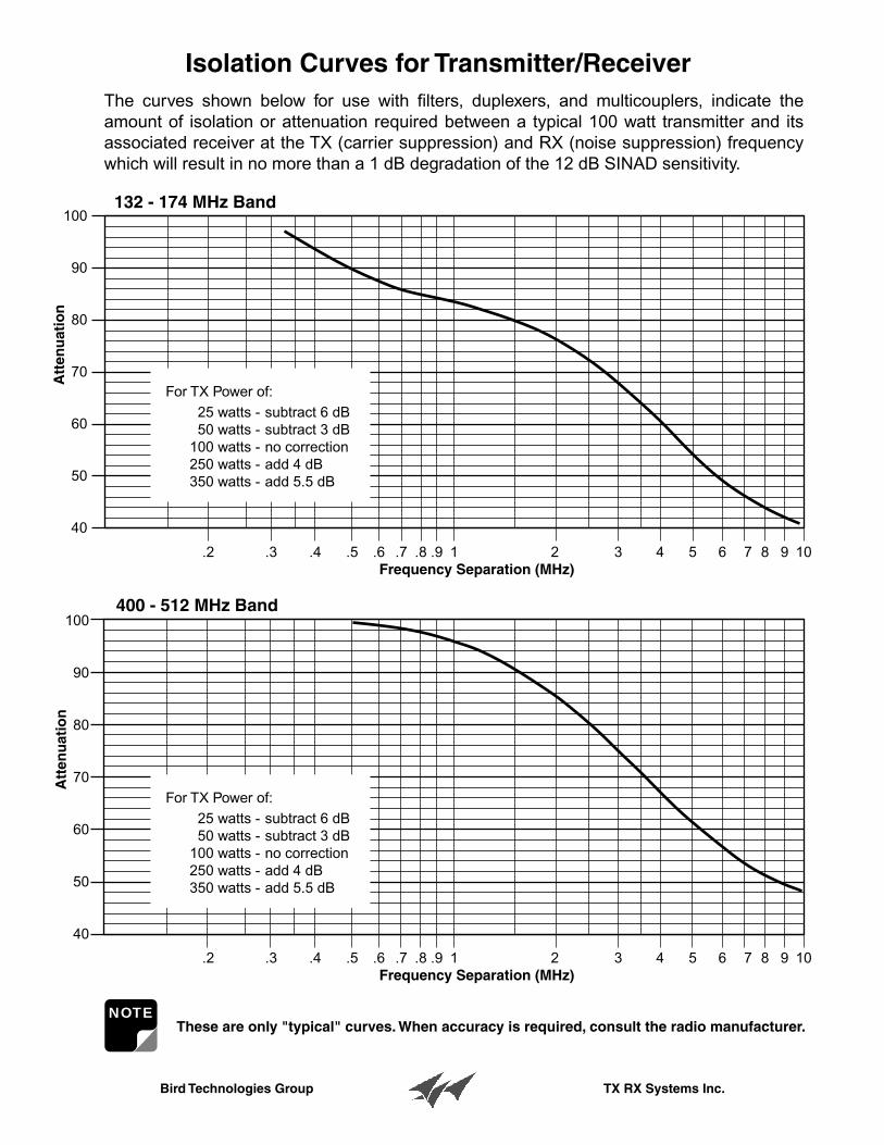
nIsolation Curves for Transmitter/Receiver
These are only "typical" curves. When accuracy is required, consult the radio manufacturer.NOTE
The curves shown below for use with filters, duplexers, and multicouplers, indicate the amount of isolation or attenuation required between a typical 100 watt transmitter and its associated receiver at the TX (carrier suppression) and RX (noise suppression) frequency which will result in no more than a 1 dB degradation of the 12 dB SINAD sensitivity.
For TX Power of:25 watts -50 watts -
100 watts -250 watts -350 watts -
subtract 6 dBsubtract 3 dBno correctionadd 4 dBadd 5.5 dB
For TX Power of:25 watts -50 watts -
100 watts -250 watts -350 watts -
subtract 6 dBsubtract 3 dBno correctionadd 4 dBadd 5.5 dB
Bird Technologies Group TX RX Systems Inc.
Voltage Ratio
PowerRatio dB Voltage
RatioPowerRatio
1 1 0 1 1
0.989 0.977 0.1 1.012 1.0230.977 0.955 0.2 1.023 1.0470.966 0.933 0.3 1.035 1.072
0.955 0.912 0.4 1.047 1.0960.944 0.891 0.5 1.059 1.1220.933 0.871 0.6 1.072 1.148
0.923 0.851 0.7 1.084 1.1750.912 0.832 0.8 1.096 1.2020.902 0.813 0.9 1.109 1.23
0.891 0.794 1 1.122 1.2590.881 0.776 1.1 1.135 1.2880.871 0.759 1.2 1.148 1.318
0.861 0.741 1.3 1.161 1.3490.851 0.724 1.4 1.175 1.380.841 0.708 1.5 1.189 1.413
0.832 0.692 1.6 1.202 1.4450.822 0.676 1.7 1.216 1.4790.813 0.661 1.8 1.23 1.514
0.804 0.646 1.9 1.245 1.5490.794 0.631 2 1.259 1.5850.785 0.617 2.1 1.274 1.622
0.776 0.603 2.2 1.288 1.660.767 0.589 2.3 1.303 1.6980.759 0.575 2.4 1.318 1.738
0.75 0.562 2.5 1.334 1.7780.741 0.55 2.6 1.349 1.82
0.733 0.537 2.7 1.365 1.8620.724 0.525 2.8 1.38 1.9050.716 0.513 2.9 1.396 1.95
0.708 0.501 3 1.413 1.9950.7 0.49 3.1 1.429 2.042
0.692 0.479 3.2 1.445 2.089
0.684 0.468 3.3 1.462 2.1380.676 0.457 3.4 1.479 2.1880.668 0.447 3.5 1.496 2.239
0.661 0.437 3.6 1.514 2.2910.653 0.427 3.7 1.531 2.3440.646 0.417 3.8 1.549 2.399
0.638 0.407 3.9 1.567 2.4550.631 0.398 4 1.585 2.5120.624 0.389 4.1 1.603 2.57
0.617 0.38 4.2 1.622 2.630.61 0.372 4.3 1.641 2.6920.603 0.363 4.4 1.66 2.754
0.596 0.355 4.5 1.679 2.8180.589 0.347 4.6 1.698 2.8840.582 0.339 4.7 1.718 2.951
0.575 0.331 4.8 1.738 3.020.569 0.324 4.9 1.758 3.09
0.562 0.316 5 1.778 3.1620.556 0.309 5.1 1.799 3.2360.55 0.302 5.2 1.82 3.311
0.543 0.295 5.3 1.841 3.3880.537 0.288 5.4 1.862 3.4670.531 0.282 5.5 1.884 3.548
0.525 0.275 5.6 1.905 3.6310.519 0.269 5.7 1.928 3.7150.513 0.263 5.8 1.95 3.802
0.507 0.257 5.9 1.972 3.890.501 0.251 6 1.995 3.9810.496 0.246 6.1 2.018 4.074
0.49 0.24 6.2 2.042 4.1690.484 0.234 6.3 2.065 4.2660.479 0.229 6.4 2.089 4.365
0.473 0.224 6.5 2.113 4.4670.468 0.219 6.6 2.138 4.5710.462 0.214 6.7 2.163 4.677
0.457 0.209 6.8 2.188 4.7860.452 0.204 6.9 2.213 4.8980.447 0.2 7 2.239 5.012
0.442 0.195 7.1 2.265 5.1290.437 0.191 7.2 2.291 5.2480.432 0.186 7.3 2.317 5.37
0.427 0.182 7.4 2.344 5.4950.422 0.178 7.5 2.371 5.623
0.417 0.174 7.6 2.399 5.7540.412 0.17 7.7 2.427 5.8880.407 0.166 7.8 2.455 6.026
0.403 0.162 7.9 2.483 6.1660.398 0.159 8 2.512 6.310.394 0.155 8.1 2.541 6.457
0.389 0.151 8.2 2.57 6.6070.385 0.148 8.3 2.6 6.7610.38 0.145 8.4 2.63 6.918
0.376 0.141 8.5 2.661 7.0790.372 0.138 8.6 2.692 7.2440.367 0.135 8.7 2.723 7.413
0.363 0.132 8.8 2.754 7.5860.359 0.129 8.9 2.786 7.7620.355 0.126 9 2.818 7.943
0.351 0.123 9.1 2.851 8.1280.347 0.12 9.2 2.884 8.3180.343 0.118 9.3 2.917 8.511
0.339 0.115 9.4 2.951 8.710.335 0.112 9.5 2.985 8.9130.331 0.11 9.6 3.02 9.12
0.327 0.107 9.7 3.055 9.3330.324 0.105 9.8 3.09 9.550.32 0.102 9.9 3.126 9.772
Voltage Ratio
PowerRatio dB Voltage
RatioPowerRatio
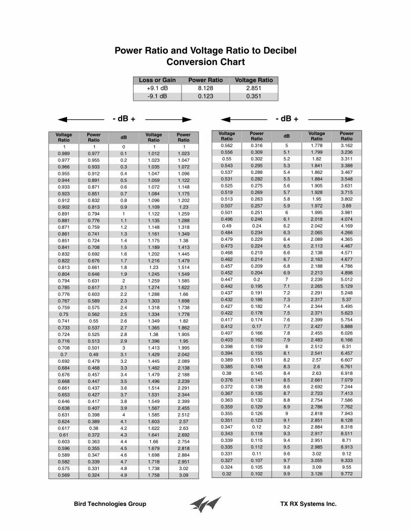
Power Ratio and Voltage Ratio to DecibelConversion Chart
Loss or Gain Power Ratio Voltage Ratio+9.1 dB 8.128 2.851-9.1 dB 0.123 0.351
- dB +- dB +
Bird Technologies Group TX RX Systems Inc.
500
400
300
250
200
150
125
100
75
50
50 75 100 125 150 200 250 300 400 500
7.0
6.5
6.0
5.5
5.0
4.5
4.0
3.5
3.0
2.5
2.0
1.5
1.0
.50
.25
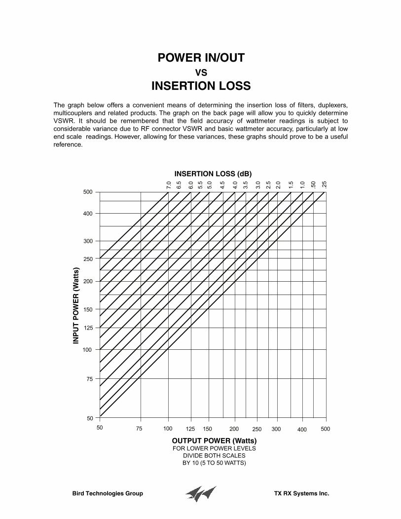
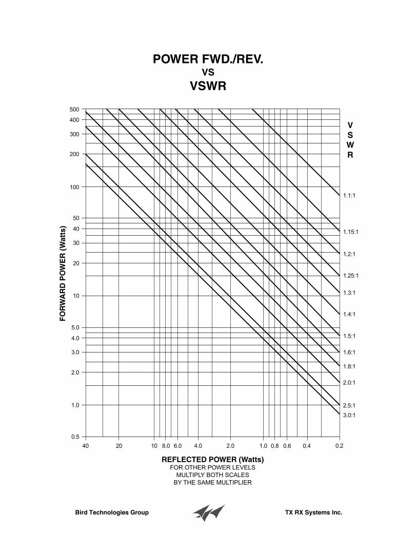
The graph below offers a convenient means of determining the insertion loss of filters, duplexers, multicouplers and related products. The graph on the back page will allow you to quickly determine VSWR. It should be remembered that the field accuracy of wattmeter readings is subject to considerable variance due to RF connector VSWR and basic wattmeter accuracy, particularly at low end scale readings. However, allowing for these variances, these graphs should prove to be a useful reference.
POWER IN/OUTVS
INSERTION LOSS
INSERTION LOSS (dB)
INP
UT
PO
WE
R (
Wat
ts)
OUTPUT POWER (Watts)FOR LOWER POWER LEVELS
DIVIDE BOTH SCALESBY 10 (5 TO 50 WATTS)
Bird Technologies Group TX RX Systems Inc.
500
400
300
200
100
50
40
30
20
10
5.0
4.0
3.0
2.0
1.0
0.5
40 20 10 8.0 6.0 4.0 2.0 1.0 0.8 0.6 0.4 0.2
1.1:1
1.15:1
1.2:1
1.25:1
1.3:1
1.4:1
1.5:1
1.6:1
1.8:1
2.0:1
2.5:1
3.0:1
FO
RW
AR
D P
OW
ER
(W
atts
)
REFLECTED POWER (Watts)FOR OTHER POWER LEVELS
MULTIPLY BOTH SCALESBY THE SAME MULTIPLIER
POWER FWD./REV.VS
VSWR
VSWR
Bird Technologies Group TX RX Systems Inc.
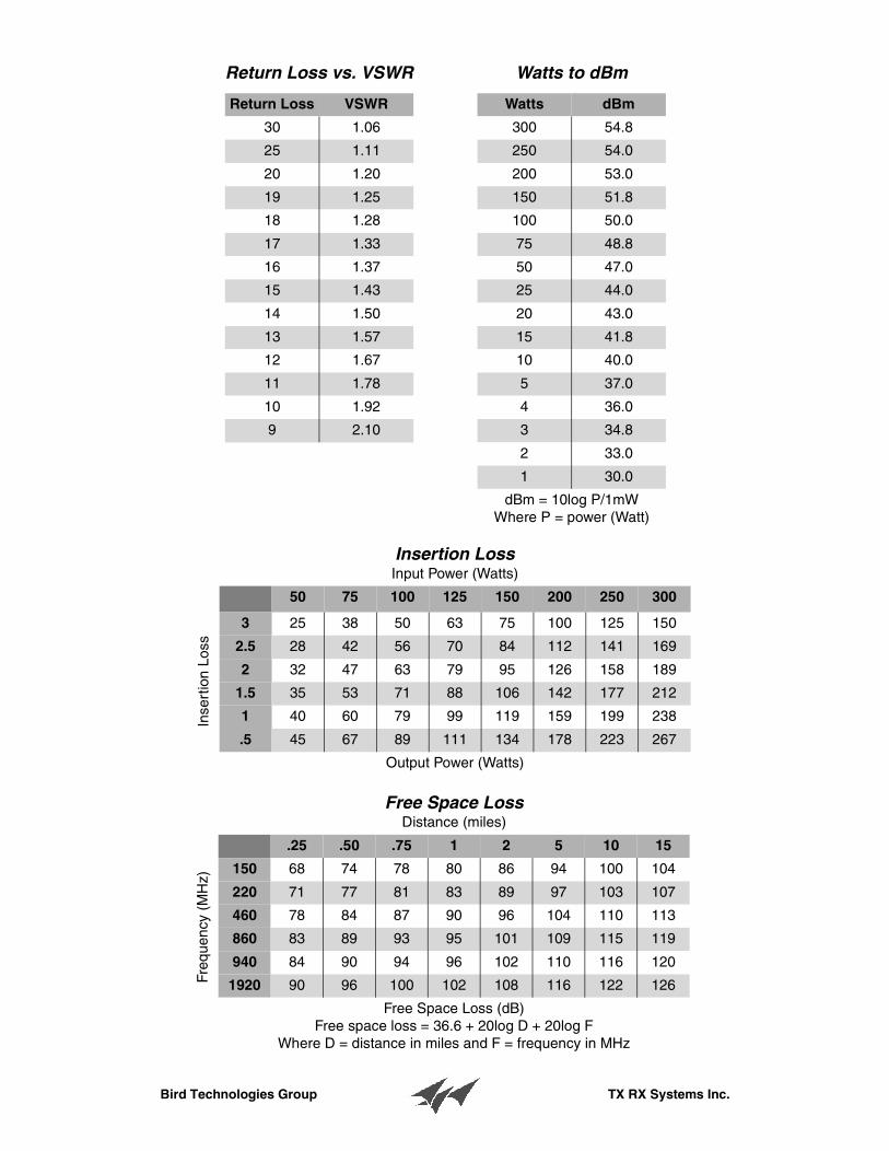
Return Loss vs. VSWR
Return Loss VSWR
30 1.06
25 1.11
20 1.20
19 1.25
18 1.28
17 1.33
16 1.37
15 1.43
14 1.50
13 1.57
12 1.67
11 1.78
10 1.92
9 2.10
Watts to dBm
Watts dBm
300 54.8
250 54.0
200 53.0
150 51.8
100 50.0
75 48.8
50 47.0
25 44.0
20 43.0
15 41.8
10 40.0
5 37.0
4 36.0
3 34.8
2 33.0
1 30.0
dBm = 10log P/1mWWhere P = power (Watt)
Insertion LossInput Power (Watts)
50 75 100 125 150 200 250 300
3 25 38 50 63 75 100 125 150
2.5 28 42 56 70 84 112 141 169
2 32 47 63 79 95 126 158 189
1.5 35 53 71 88 106 142 177 212
1 40 60 79 99 119 159 199 238
.5 45 67 89 111 134 178 223 267
Output Power (Watts)
Inse
rtio
n Lo
ss
Free Space LossDistance (miles)
.25 .50 .75 1 2 5 10 15
150 68 74 78 80 86 94 100 104
220 71 77 81 83 89 97 103 107
460 78 84 87 90 96 104 110 113
860 83 89 93 95 101 109 115 119
940 84 90 94 96 102 110 116 120
1920 90 96 100 102 108 116 122 126
Free Space Loss (dB)Free space loss = 36.6 + 20log D + 20log F
Where D = distance in miles and F = frequency in MHz
Freq
uenc
y (M
Hz)


![012...!!!Z[Ü4’#‘’—–&!!!ÝÞøW’ßàHÆ&!!!"Y_‘’8â—–&!!!ªäY]8“ä&!!!Hƈå9xÙˆ&!!!_‘µæ‰•$ ($)!vwxyGgwij ($)$&!vwxy ($)$&$&!JKxoçRSçr](https://img.pdfslide.net/doc/110x75/5f7bc609b2650322af75d122/012-zoe4aaaaawahyaa8aay8aoeh9xaaa.jpg)


![[Credentials];[Notch JSC]](https://img.pdfslide.net/doc/110x75/5442a5f9b1af9f350a8b46f3/credentialsnotch-jsc.jpg)