Embed Size (px)
Citation preview

Instruction Manual Ver 1.0

2
Fly high with Hitec
Table of Contents
Thank you for purchasing Hitec’s Sky Scout.Developed and engineered by Multiplex, manufactured by Hitec, the Sky Scout is an ideal model for all users interested in model flying, regardless of age or gender. The Sky Scout is easy to fly, even for beginners. This instruction manual includes the model specifications, safety precautions and assembly instructions for the KIT version of the Sky Scout. Please be sure to read this manual in its entirety before beginning the assembly and operation of your Sky Scout Model Kit.
Warning : Be sure to read this section for your own safety. Caution : Be sure to read this section to prevent accidents and damage to your model.Tip : This section will help you maximize the performance of your model. Note : This section will provide more detailed explanations.
The Sky Scout is a radio control model plane designed for users over age 14. For those under age 14, please seek the help of your parents, guardian or the help of a skilled RC pilot. Improper assembly or user negligence can lead to serious injury and/or property damage to yourself or other persons. Hitec is not responsible for any damages or injuries caused by the user’s negligence or improper assembly of the model. Be sure to read the instruction manual thoroughly before assembly and flying.
The Sky Scout is manufactured of ELAPOR, a material highly suited for model airplanes. ELAPOR is light, durable and unlike traditional foams it can be bonded successfully with traditional cyanoacrylate adhesives and activators. Do not use foam-safe or “odorless” CA, epoxy or other household glues. It is recommended that you wear safety goggles when using CA glue and be sure to follow the manufacturer’s safety instructions for its use.
Specifications Wingspan: 1366mm (53.75 in.)Overall length: 977mm (38.5 in.)Min. all-up weight, standard: 700g (24.7 oz.)Wing area, approx.: 28dm2 (434 sq. in.) (wing + tailplane, excl. fuselage)Min. wing loading: 25g / dm2 (8.2 oz/sq ft)RC functions: rudder, elevator and throttle; optional ailerons
Section One: Introduction & Specifications
Section One: Introduction Introduction & Specifications Recommended Equipment Other Sky Scout Versions Safety Precautions
Section Two: Model Assembly Cautionary Notes Tools and Supplies Needed for Assembly Parts Layout and Listing Assembly Instructions
Section Three: Preparing Your Model for Flight
Section Four: Flying Your Model Pre-Flight Inspections Taking Off Controlling the Plane Landing the Plane
Section Five: Maintaining Your Model Replacement Parts and Components Customer Service Information
Appendix A: The Basics of Model Flying
Appendix B: Transmitter Control Surface Movements
2334
5568
15
16171717
1820
21
23

3
Fly high with Hitec
Section One: Recommended Equipment (sold separately)
The KIT version of the Sky Scout only includes the airframe, associated hardware, along with the prop and spinner assembly. The following additional parts and equipment are needed to complete the assembly. Visit a Radio Control Hobby shop or consult an experienced flier about purchasing the right equipment for your needs.
1. 3-4 Channel Aircraft RadioThe Sky Scout requires at least a 3-channel radio to fly. Adding the optional ailerons requires a 4th channel, though a 5 or higher channel radio with mixing features will allow for additional flight performance. We recommend Hitec models such as the Optic 5 or Optic 6 Sport for optimal operational performance
2. ReceiverWe recommend at least a 5 channel aircraft receiver that matches your radio system for maximum flexibility. Models such as the Hitec Minima 6T or 6S will fit this need if you are using a Hitec brand 2.4 GHz Radio.
3. Servos You will need at least two Sub Micro servos to complete your model. If you choose to add the optional ailerons you will need an additional two sub-micro servos. Hitec recommends using the HS-55 or HS-5055MG on all surfaces. These servos are available at most Radio ControlHobby stores.
4. Motor You will need a brushless outrunner motor designed for aircraft use. We recommend the minimum of a 200-watt 1100Kv motor. The motor dimensions need to be no more than 28mm in diameter and 28mm in length. To avoid having to use a special adapter make sure the output shaft is either 3 or 3.2 mm in diameter. The Sky Scout Kit contains Prop adapters in both of these sizes.
5. ESCYou will also need an Electronic Speed Control with built in BEC that is suitable for the motor you purchased. Hitec recommends using an ESC with a minimum rating of an 18A and a BEC output of at least 1.5 amps
6. Battery & ChargerFor optimal performance Hitec recommends a 3-cell 11.1V 1300mAh LiPo battery with at least a 15C discharge rating. You will also need a charger capable of charging this battery as well. tions you are using.
3-4 CH AIR TX
1
RECEIVER
2
SERVOS
3
Section One: Other Sky Scout Versions
Radio, Receiver and Power Set Components for Each Version
(READY TO GO) stock# 13207 This version includes everything you need to fly your Sky Scout after a few easy assembly steps. Semi-assembled modelSemi-assembled modelHitec Lite 4 2.4GHz 4-channel Radio (w/4AA aIkaline batteries)Hitec Minima 6S Receiver (installed)Hitec HS-55 Servos (installed)
(HITEC TO GO) stock# 13209 This version allows you to fly your Sky Scout with the Hitec radio you already have or may wish to purchase. Any of Hitec’s AFHSS 2.4GHz radios, or radios using a Spectra 2.4GHz module, can be linked with the Minima 6S included in the H2GO set.
Semi-assembled modelHitec Minima 6S Receiver (installed)Hitec HS-55 Servos (installed)C2812-1100 Brushless Outrunner Motor (installed)
(PLUG-IN TO GO) stock# 13210 This Sky Scout version is for modelers who already own the additional products needed for flying. A transmitter, receiver, charger and suitable batteries are required needed to fly the model plane.
Semi-assembled modelHitec HS-55 Servos (installed)C2812-1100 Brushless Outrunner Motor (installed)Hitec HBE-18A ESC (installed)
C2812-1100 Brushless Outrunner Motor (installed)Hitec HBE-18A ESC (installed)HLP-3S 1300mah Li-Po battery (included)CG-115 DC Balancing Charger (included)
Hitec HBE-18A ESC (installed)HLP-3S 1300mah Li-Po battery (included)CG-115 DC Balancing Charger (included)
CHARGER
6
BATTERY &ESC
5
MOTOR
4

4
Fly high with Hitec
Section One: Safety Precautions
The product contains small and sharp components. Please be sure to keep them away from children at all times.
Be sure to connect the batteries with the right polarity. Disconnect the battery if it is damaged or produces excessive heat.
Be careful when using tools like knives, scissors and screwdrivers.
Keep away from rotaing propellers to prevent injuries.
The motor and battery may produce heat during the pre-flight test or during the flight. Be sure to cool them off before touching them or recharging the battery.
Do not fly in strong winds or storms. The Sky Scout may not perform as desired.
Always disconnect the batteries from the the model when its not in use. Leaving the battery connected may cause it to overheat may damage the model.
Do not use or attempt to repair a distorted or damaged spinner or propeller blade. They may fail under operation, risking injury or property damage.
Do not store the Sky Scout or accessories in humid, closed areas, in high temperatures or in direct sunlight.
Be sure to use official Hitec products and components. Altered products may negatively affect the model’s performance.
Link
Lithium-Polymer (LiPo) batteries can pose significant risk when mishandled. Keep them away from fire to prevent explosion and unplug immediately if they feel hot or show signs of swelling.
Do not separate individual cells or stab the battery with a sharp tool. The battery may explode and cause injuries.Only recharge your LiPo batteries with a dedicated LiPo charger such as the Hitec CG-115 DC Charger. Do not attempt to recharge with a charger designed for NiCd or NiMH cells.
Link
V-TAILOFFELEVON
CH1 CH2 CH3 CH4REV
NOR
2.4GHz
4
Channel
Aircraft
Radio
5
Fly high with Hitec
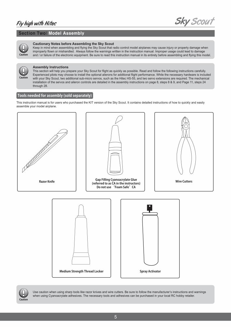
Cautionary Notes before Assembling the Sky ScoutKeep in mind when assembling and flying the Sky Scout that radio control model airplanes may cause injury or property damage when improperly flown or mishandled. Always follow the warnings written in the instruction manual. Improper usage could lead to damage and / or failure of the electronic equipment. Be sure to read this instruction manual in its entirety before assembling and flying this model.
Assembly InstructionsThis section will help you prepare your Sky Scout for flight as quickly as possible. Read and follow the following instructions carefully. Experienced pilots may choose to install the optional ailerons for additional flight performance. While the necessary hardware is included with your Sky Scout, two additional sub-micro servos, such as the Hitec HS-55, and two servo extensions are required. The mechanical installation of the servos and aileron controls are detailed in the assembly instructions on page 8, steps 8 & 9, and Page 11, steps 24 through 28.
Section Two: Model Assembly
This instruction manual is for users who purchased the KIT version of the Sky Scout. It contains detailed instructions of how to quickly and easily assemble your model airplane.
Razor Knife
Medium Strength Thread Locker
Gap Filling Cyanoacrylate Glue (referred to as CA in the instructors)
Do not use “Foam Safe”CA
Use caution when using sharp tools like razor knives and wire cutters. Be sure to follow the manufacturer’s instructions and warnings when using Cyanoacrylate adhesives. The necessary tools and adhesives can be purchased in your local RC hobby retailer.
Tools needed for assembly (sold separately)
Spray Activator
Wire Cutters
6
Fly high with Hitec
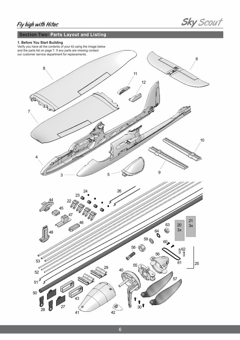
1. Before You Start Building Verify you have all the contents of your kit using the image below and the parts list on page 7. If any parts are missing contact our customer service department for replacements.
Section Two: Parts Layout and Listing

7
Fly high with Hitec
Section Two: Parts Layout and Listing
Part No. Description Material Dimensions
Small Parts set
Plastic parts set
Wire / rod set, wing joiner
Propeller, driver, spinner set, Sky Scout
1 1.1 2A 2B 3456789101112
11111111111111
33444122223
111211111
1223
11211212111
Building instructions, KITComplaints form, modelsDecal sheet ADecal sheet BL.H. fuselage shellR.H. fuselage shell, with finCanopy Tailplane L.H. wing panel R.H. wing panelL.H. joiner channel coverR.H. joiner channel cover L.H. servo well coverR.H. servo well cover
Velcro tape, hookVelcro tape, loop Twin control surface hornSwivel barrelAllen-head grubscrewAllen key Pre-formed aileron pushrod Latch catch Latch tongue Cable holder Screw (motor cowl)
FirewallMotor cowlCowl screw supportServo mount, „Nano“, uprightTailplane clipUpper tailplane sleeveLower tailplane sleeveTailplane frameTailplane slider
Propeller bossSpinnerFolding propeller bladePropeller driver, taper colletWasherPan-head self-tapping screwO-ringDowel pinNutShakeproof washerTaper collet
Wing joinerPre-formed pushrod, ele. / rud.Snake inner tube, ele. / rud.Snake outer sleeve, elevator
Printed self-adhesive filmPrinted self-adhesive filmMoulded Elapor foamMoulded Elapor foamMoulded Elapor foamMoulded Elapor foamMoulded Elapor foamMoulded Elapor foamMoulded Elapor foamMoulded Elapor foamMoulded Elapor foamMoulded Elapor foam
PlasticPlasticPlasticMetalMetalMetalMetalInj.-moulded plasticInj.-moulded plasticInj.-moulded plasticMetal
Inj.-moulded plasticInj.-moulded plasticInj.-moulded plasticInj.-moulded plasticInj.-moulded plasticInj.-moulded plasticInj.-moulded plasticInj.-moulded plasticInj.-moulded plastic
GRP tubeMetalPlasticPlastic
PlasticPlasticPlasticMetalMetalMetalPlasticMetalMetalSpring steelMetal
200 x 820 mm200 x 700 mmReady-madeReady-madeReady-madeReady-madeReady-madeReady-madeReady-madeReady-madeReady-madeReady-made
25 x 60 mm25 x 60 mmReady-madeReady-made, 6 mm ØM3 x 3 mm1.5 mm A/F1 Ø x 80 mmReady-madeReady-madeReady-made2,2 x 6,5 mm
Ready-madeReady-madeReady-madeReady-madeReady-madeReady-madeReady-madeReady-madeReady-made
8.0 Ø x 5.4 x 579 mm0.8 Ø x 620 mm2/1 Ø x 550 mm3/2 Ø x 950 mm
Ready-made35 mm Ø7 x 6 in.3.2 Ø / M6 / hex-head, 13 A/F6.4 I.D.2.2 Ø x 6.5 mm30 Ø x 1.5 mm3 Ø x 14 mmM66.4 I.D.3.0 Ø / M6 / hex-head, 13 A/F
202122232425 2627282930
404142434445464748
50515253
5556575859606162636466
Qty.

8
Fly high with Hitec
Section Two: Assembly Instructions
3. Reinforcing the motor podGlue the 31 mm length of snake outer sleeve inside the motor pod using CA glue.
6. Reinforcing the bottom of the fuselageCut the outer snake sleeve to a length of 635 mm, then glue itin the channel in the bottom of the right-hand fuselage shell 4.Temporarily fit the tailplane slider 48 to position this partaccurately, but take care not to glue the parts together.
5. Inserting the tailplane sliderAllow the glue to set hard, then insert the tailplane slider 48 to ensure that the parts are accurately aligned. This part must not be glued in place!
2. Prepare Snake SleevesCut Parts #52 & #53 to lengths as shown using a razor knife.
Take care not to glue together the two plastic parts(tailplane clip 44 and upper tailplane sleeve 45)!
4. Installing the tailplane lockGlue the tailplane clip 44, the upper tailplane sleeve 45 and the tailplane frame 46 in the right-hand fuselage shell 4: lightly spray activator thinly on the plastic parts, and allow a few seconds for the fluid to air-dry.

9
Fly high with Hitec
Section Two: Assembly Instructions
8. Preparing the cable holders (optional: required for ailerons)Glue the female plug end of a 12” (30mm) servo extension lead to the cable holder 29, flush with the edge. Push the cable under the lug on the underside.
10. Gluing the latch catches in placeGlue the latch catches 27 in both fuselage shells. Once again, spray activator onto the plastic part, and allow it to air-dry.
11. Installing the servo mountsGlue both servo frames 43 in the appropriate openings using CA Glue. Ensure that no glue gets onto the mount lugs, as this could prevent them holding the servos securely.
7. Reinforcing the fuselage noseCut the sleeves to a length of 247 mm, and glue them in the upper part ofthe two fuselage shells 3 + 4. Cut the sleeve to a length of 290 mm and glue it in the underside of the right-hand fuselage shell 4.
9. Installing the cable holdersFirst spray activator on the joint surfaces of the cable holders 29. Allow the fluid to air-dry, then glue the parts in the appropriate recesses in both fuselage shells.

10
Fly high with Hitec
Section Two: Assembly Instructions
12. Preparing the servos for installation Before installing the servos, set all of them to neutral (center) from the transmitter: this is accomplished by connecting the servo to a receiver, switching the system on, and centring the stick at the transmitter; check that the transmitter trims are also at the neutral position. Locate the “double-ended” servo output levers with three holes per side, fit them on the servo output shafts at right-angles to the long side of the servo cases. If you find that the output arm is not accurately at right-an-gles to the case when the servo is at neutral, rotate the lever through 180° and try again; the output shaft features an odd number of splines, and reversing the output device will get you “closer to the target”.Install the elevator and rudder servos as a mirror-image pair. You will do the same with the aileron servos, if you choose to install them.
13. Installing the servos in the fuselageFit the servos in the servo mounts 43, with the output arms facing down, and the output shafts towards the nose. Trim the unused output arm if needed to prevent interference with the fuselage.
14. Joining the fuselage shellsSpray the joint surfaces of one fuselage shell with activator, apply medi-um-viscosity CA glue to the joint surfaces of the other shell, then quickly join the two shells, making sure to align the parts accurately.
15. Installing the snakesSlip the pre-formed steel pushrods 51 for the elevator and rudder into the inner tubes 52 (550 mm), and fit these into the prepared outer sleeves 53, which are 523 mm long.Connect the pre-formed end of the pushrod to the second hole from the outside of the servo output arm. Glue the snake outers in the appropriate channels, running CA glue right along the channel.
17. Attaching the horns to the rudder and elevatorSpray activator on the joint surface (the underside) of the horns. Apply CA Glue to the horn recesses in the elevator 6 and rudder. Leave the fluid to air-dry for a few seconds, then press the horns into their recesses.Slip the steel pushrod for the rudder linkage through the hole in the swivel barrel 23. Check once more that the servos are at center before tightening the allen-head grubscrews 24. We recommend that you apply a drop of medium-strength thread-lock fluid to each grubscrew to prevent them working loose over time.
16. Preparing the control surface hornsFit the allen-head grubscrews 24 in the swivel barrels 23: two for elevator and rudder, four if working ailerons are to be fitted. Engage the prepared swivel barrels in the “Twin” horns 22.
Avoid moving the servo output levers by hand, as this can easily ruin the gears!

11
Fly high with Hitec
Section Two: Assembly Instructions
18. Installing the tailplane frameTo guarantee a secure seating, the tailplane frame 47 must be glued in the recess of the tailplane 6.
19. Attaching the tailplaneFirst withdraw the tailplane slider 48 slightly, then insert the tailplane 6 and push the slider back in as far as it will go to secure the tailplane. Do not glue it! The tailplane should be left detachable for safe, convenient transport. To remove the tailplane, press the tailplane clips 44 together with two fin-gers, and at the same time pull the tailplane slider 48 down; the tailplane can now be removed.
20. Connecting the elevatorSlip the inner pushrod for the elevator through the hole in the swivel barrel 23, and check the servo neutral position once more before tightening the allen-head grubscrew 24. We recommend that you apply a drop of medium-strength thread-lock fluid to the grubscrew to prevent it working loose over time.
21. Releasing the control surfacesUse a sharp razor knife to remove the foam at the lateral ends of the con-trol surfaces, cutting along the moulded-in end channels only. Repeatedly move the control surfaces to and fro in order to loosen the integral hinges and render them freemoving. Do not separate the control surfaces!
23. Installing the wing joiner channel coverCarefully glue the wing joiner channel covers 9 and 10 in the wing panels 7 and 8. Take particular care to avoid glue running onto the surfaces which will later make contact with the wing joiner 50. Check that the wing joiner 50 is a snug fit in the wings, but only when you are absolutely confident that there is no active adhesive inside the channel. If you neglect this, youcould find that the model is glued together permanently.
22. Attaching the servo well coversPress the left and right servo well covers 11 and 12 into the openings in both sides of the fuselage. They should not be glued in place, as you may have to replace the servos at some time.

12
Fly high with Hitec
Section Two: Assembly Instructions
24. Attaching the (optional) aileron hornsAssemble the “Twin” horns 22, and glue them in the recesses in both ailerons (wing panels 7 + 8) using CA Glue and activator, as described earlier.
28. Installing the cable sleevesTo avoid kinking the aileron servo leads, glue 18 mm lengths of snake outer sleeve (3.2mm OD) in the recess where the cables exit the wing.
29. Installing the firewallGlue the firewall 40 in place using thick CA glue. Don’t use activator for this joint, as you will need a certain amount of time to position and align the firewall correctly.
30. Gluing the cowl screw support in placeGlue the cowl screw support 42 at the front end of the motor pod.
26. Installing the aileron servosWrap adhesive tape round the servos to prevent glue running inside the case.Fit the pre-formed aileron pushrods 26 through the second hole from the outside of the servo output arms. Press the servos and leads into the recesses and channels, and thread the plain end of the pre-formed aileron pushrods 26 through the swivel barrels mounted on the aileron horns.Check once more that the servos are at center before tightening the grub-screws 24 in the swivel barrels. We recommend applying a drop of medium-strength thread-lock fluid to the grubscrews to prevent them working loose.
27. Servo lead length, aileron connectionsDraw the servo leads out of the wings 7 + 8 where the wing meets the fuselage.
25. Preparing the aileron servosSee “10. Preparing the servos”.

13
Fly high with Hitec
Section Two: Assembly Instructions
31. Installing the motorFix the motor in place using two M3 x 6 screws. Apply a drop of medium-strength thread-lock fluid to the screws.
32. Installing the motor cowlFit the three screws 30 to secure the motor cowl 41.
33. Assembling the propellerAttach the propeller blades 57 to the propeller boss 55 usingthe two dowel pins 62.
Fold the propeller blades 57 back, and pass them through the ends of the O-ring 61 which project from the sides of the spinner. Take care to avoid the sharp edges of the propeller blades causing dam-age to the O-ring 61. Fix the spinner to the propeller boss 55 using the two pan-head self-tapping screws 60.
Fit the O-ring 61 through the spinner cone 56.
Slip the tapered collet through the driver 58 and place this assembly in the propeller boss 55. The washer 59 and the shakeproof washer 64 are fitted from the other side. Screw the M6 nut 63 on the taper collet 58. Fit the taper collet 58 on the motor shaft and tighten the nut firmly before fitting the spinner.

14
Fly high with Hitec
Section Two: Assembly Instructions
34. Completing the canopyGlue the latch tongues 28 in the recesses in the canopy 5.Use thick CA glue initially, and fit the canopy on the model immediately, so that the latch components align themselves automatically. Wait for at least two minutes before removing the canopy, then apply drops of thin CA glue to the gaps in the latches to glue them in place, flush with the foam.
36. Installing the flight battery and receiverDeploy the receiver aerial(s) as described in the RC system instructions. The aerial tube installed in the underside of the fuselage is intended for conventional MHz systems. If you are using a 2.4GHz system, cut slits in the foam material (e.g. in the area of the canopy flange) and press the short aerials into them.
NOTE: When positioning these components you should bear in mind the recommended Center of Gravity (CG) at point 40. Stick the strips of Velcro tape 20 and 21 (loop side) to the inside of the fuselage floor. Note that the adhesive on the tape is not adequate for this application, so fix the tape with CA glue for additional security.The final position of the flight battery is determined when you check the model’s balance point (Center of Gravity - CG). Check to make sure that the Velcro tape for the flight battery is firmly secured. If you neglect this, your battery could come loose in flight. Always check that the flight pack is secure before every flight!
Connect the servo leads to the receiver. Switch the transmitter on, then connect the flight battery in the model to the speed controller, and the controller to the receiver. This model requires a BEC-type speed controller (receiver power supply from the flight battery).
Now switch the motor on briefly, and check once more that the propeller rotates in the correct direction (clockwise looking at the spinner). If it spins in the reverse direction, switch any two of the three motor wires to correct it.
Always hold the model securely when testing the power system, and remove any loose, lightweight objects before and behind the model before the propeller does it for you.
37. Finishing the modelThe kit includes a multi-color decal sheet (A + B) for adding the final touches to the model. Cut out the individual decals and apply them to the airplane in the arrangement shown on the box illustration.The canopy can be colored black using a waterproof felt-tip pen. If you wish to apply an all-over color scheme, you can use most common spray enamel paints available at your local hardware store. You must use caution and not over apply the paint instead spraying several light coats. For tips on painting our models please refer to the FAQ section on our website.
35. Installing the wingsSlide the wing joiner 50 into one of the wing panels as shown in the illustration, then fit the joiner through the fuselage. Before the wing makes contact with the fuselage, connect the aileron servo lead to the extension lead already installed in the fuselage. Connect the plug and socket, then push the wing fully into place; the cable will now form itself into a loop in the space designed for it. Fit the other wing panel onto the joiner, and connect the aileron servo lead to the extension lead already installed in the fuselage, as described previously.
Do not connect the battery to the speed controller until you have switched the transmitter on, and are certain that the throttle control is at the “OFF” position. Even small motors and propellers are capable of inflicting injury!

15
Fly high with Hitec
Section Three: Preparing Your Model for Flight
Before attempting flight ensure that your controls are set up properly and give the appropriate response to your transmitter inputs. A complete set up guide appears at the end of this manual in Appendix B: Transmitter Control Surface Movements. If you have any questions about this consult with a local experienced flier or your local RC Hobby Retailer or contact Hitec Customer Support.
1. Check Transmitter Inputs
It is important to set the correct control surface travels, otherwise your model will not respond to your control commands smoothly and evenly. To do this you need to complete all the electrical connections as described in the RC system instructions.NOTE: when we refer to a model aircraft, the terms “right” and “left” always apply to the model when viewed from above, with the nose pointing away from the you. ELEVATOR: Up-elevator (stick back, towards you) should be about 5 mm; down elevator (stick forward, away from you) approx. 4 mm. RUDDER: The rudder should move 10 mm to either side of center, as measured from the widest part of the control surface.AILERONS: The ailerons should deflect 8 mm up and 4 mm down. When you move the aileron stick to the right, the aileron on the right-hand wing should deflect up; that on the left-hand wing down. If your radio control system does not include the required mixing to set up differential aileron travel (as described above), the model will still fly well with symmetrical (non-differential) travels. If you are a beginner, you will probably notice no difference in any case. However, accurate rolling maneuvers are more difficult to fly with symmetrical aileron travels.NOTE: If you cannot set the recommended travels using your transmitter’s adjustment facilities, you will have to re-position the pushrod connections, using different holes at the servo or horn.
2. Setting the control surface travels
Like every aircraft, your Sky Scout must be balanced correctly if it is to fly well and stably. To check the Center of Gravity (CG) you must first assemble your model completely as if you were ready to fly, and install the flight battery.The correct CG is marked at a point about 5 mm from the rear edge of the wing joiner cover, and the model must balance at this point. This setting corresponds to about 78 mm aft of the wing root leading edge, measured either side of the fuselage.Support the model under both wings on two fingertips at the marked point, and it should balance level.Minor corrections can be made by adjusting the position of the flight battery. Once you have established the correct position for the battery, mark this in the fuselage to ensure that it is always positioned correctly.
3. Balancing the model
Safety is of the utmost importance when flying any model aircraft. Third party insurance is mandatory. If you join a model club or association, suitable coverage will usually be available through the organization. It is your personal responsibility to ensure that your insurance is adequate (i.e. that its cover includes powered model aircraft). Always fly in such a way that you do not endanger yourself or others. Bear in mind that even the best RC systems are subject to outside interference.No matter how many years of accident-free flying you have there is always the possibility of an unforeseen problem or error that can cause an accidentMake it your job to keep your models and your radio control system in perfect operating condition at all times.Check and observe the correct charging procedure for the batteries you are using.Before every flight, check that the battery, the wings and the tail panels are attached and firmly seated. Check in turn that each control surface is operating correctly!
Where to fly – Using Airfields 1) Use an official model airfield if possible when flying your model. 2) Check that other pilots and spectators are positioned safely before flying your model. 3) Wait for other pilots to land their models if they are flying already. 4) Always remember that the pilot is responsible for any outcome that may occur during the flight. 5) Do not fly the plane behind yourself or others. 6) Seek help from an experienced pilot for your first flight. 7) Do not fly under the influence of alcohol or drugs or if you are feeling ill. 8) Be sure to do pre-flight safety checks of the model before flying.
4. Safety
If you have no prior experience with flying a radio controlled model, please take the time to read through the “Appendix A” entitled “The basics of model flying”.

16
Fly high with Hitec
The following checks are done with the radios system turned on and the model’s main battery plugged in and fully charged. Be sure to turn on the transmitter and check to make sure that the throttle is in the OFF position BEFORE connecting the main battery. If using a conventional XX MHz fre-quency system, ensure that your chosen channel is free before beginning these tests. a) Range Check: Follow the instructions provided by your RC system manufacturer. The transmitter battery and flight pack must be fully charged in accordance with the manufacturer’s recommendations before conducting this test. b) Function Check: Check to make sure the model responds correctly to the transmitter inputs.
If you are unsure about the proper range, operation or functionality of any part of the radio system, do not fly the model! If you cannot identify and solve the problem, send the whole RC system (including battery, switch harness and servos) to your system manufacturer for inspection.
The following inspection should be done BEFORE plugging in the battery. a) Check to make sure the models is in safe operating condition and that there is no damage to the wings or the tail. b) Check to ensure the wings and tail plane are properly seated and locked into position c) Make sure the prop and hub are tightly mounted to the motor d) Make sure the propeller spins freely and that the blades open and close properly
1. Pre-flight Model Inspection
2. Pre-flight Radio Check
The following is based on common safety precautions for flying RC models. Please read the following information before attempting to fly your model. Check all safety aspects of your model before flying for a safe flight.
Pre-Flight Inspections and Cautionary Notes
Pre-flight safety checks
The following instructions are for users to easily understand what to check for before the flight how to take-off, land and adjust settings during the flight. The instruction manual cannot address every situation that may occur, but it does explain common situations that occur which could be useful for you when flying.
1. Check whether the wings or the tail are damaged.2. Check if the joints and the propeller are assembled firmly.3. Connect the main battery AFTER turning on the transmitter. Keep away from other people, and especially away from the propeller.4. Once the main battery is connected the motor could start suddenly for many reasons or due to an error. Be sure to have another person hold the model down before connecting the battery or turning the power on.5. Check whether the model responds correctly to the radio signals.
Section Four: Flying Your Model
Maiden Flight
For the first flight wait for a day with as little breeze as possible; the evening hours often offer calmer conditions The aircraft is designed to be hand-launched (always into wind). If you are a beginner to model flying, we strongly recommend that you ask an experienced modeler to help you for the first few flights. The following instructions are for users to easily understand the process of taking off, making in flight adjustments and landing the model. The instruction manual cannot address every situation that may occur, but it does explain common situations that occur which could be useful for you when flying. Beginner fliers should seek help of an experienced pilot through a friend, local club or nearby RC hobby retailer.
Using excessive control stick inputs can cause in undesired results. Control stick inputs should be small and slight until you have become familiar with the way the model behaves.

17
Fly high with Hitec
1. Taking Off
Hold the plane facing into the wind and keep it level as you apply the throttle. Now throw it smoothly forward with the nose level or angled up no more than 30-degrees. After the take-off use the control sticks to keep the wings and fuselage level as the model gains altitude. If the battery isn’t fully charged, the plane will not climb normally. Once you have climbed to an altitude of 100-130 feet (30-40 meters) high you can adjust the trim to make it fly smoothly.
Section Four: Flying Your Model
2. Adjusting the Trims
3. How to Control the Plane
4. How to Land the Plane
Even if you balance the plane properly on land, it may not fly horizontally due to the wind or weight shift. To check the trim, once you have reached your initial climb altitude, set the throttle to about ¾ power and let go of the control sticks. If the plane turns to the right, adjust the rudder trim control on your transmitter to the left. If the plane continues to climb, adjust the elevator trim up. Adjust the rudder and elevator trim controls so that the plane will fly straight and level when you let go of the control sticks. Be sure to adjust the trim only after the plane has reached an altitude of more than 130 feet (40 meters). Adjusting the trim when the plane is flying too low could cause it to crash.
The most basic flight pattern for your new plane is an oval shape. Fly the plane in one direction at a safe altitude until you are familiar with the control sticks. When moving in a straight line, slightly adjust the control sticks to keep the plane level. To turn to the left, move the rudder stick slightly to the left and note the plane’s reaction. It should begin turning to the left while also losing a little bit of altitude. To maintain its altitude in a turn a pull the elevator stick toward you slightly at the same time. To complete the turn let both sticks spring back to their neutral position. To turn to the right, move the rudder stick slightly to the right and pull the elevator stick toward you slightly at the same time. To complete the turn let both sticks spring back to their neutral position. With the aircraft flying at an adequate altitude, check how it responds when the motor is switched off, so that you are familiar with its behavior during the gliding process.Avoid flying tight turns at first, especially close to the ground, and in particular during the landing approach.
You must land the plane before the battery is too low. It is always better to land safely some distance away than to risk a crash by forcing the model back to your feet.In order to land the plane safely, have a friend first check for any obstacles or people around the intended landing area. With the model flying into the wind reduce the power so the model starts descending. Use the control sticks to keep the wings and fuselage level until it touches down. You could damage the plane if it lands too steeply on its nose or hits a wing tip first. Landing into the wind ensures the slowest possible landing and least chance of damage.
5. After Your Flight
Immediately disconnect the flight battery and then turn off your transmitter. Inspect the model for any damage and realign the wings and tail if neces-sary. Completely recharge your battery according to the manufacturer’s specifications before flying again.

18
Fly high with Hitec
Section Five: Replacement Parts and Components
#72 4607
Decal Sheet
#22 4239
Fuselage shells + snakes
#22 4240
Canopy
#22 4241
Tailplane
#22 4242 Wings
#22 4243
Small items set

19
Fly high with Hitec
Section Five: Replacement Parts and Components
#22 4244
Injected parts
#70 3457
Twin control surface horn and pushrod connector, 2 pcs.
#72 3193
Spar tube
#72 5136
Canopy-Lock (2 pair)
#73 3194
Driver, propeller boss and spinner(includes part #73 3900, 5x o-rings)
#73 3506
Driver, propeller boss and spinner(includes part #73 3900, 5x o-rings)

20
Fly high with Hitec
Section Five: Customer Service

21
Fly high with Hitec
Appendix A: The Basics of Model Flying
The basics of model flyingAny aircraft - whether model or “man-carrying” - can be controlled around three primary axes: the vertical axis, lateral axis and longitudinal axis. Operating the elevator produces a change in the aeroplane’s flight attitude around the lateral axis (pitch).Giving a rudder command turns the model around the vertical axis (yaw). If you move the aileron stick, the model rotates around the longitudinal axis (roll). All three axes can be controlled regardless of the aeroplane’s flight attitude. All aircraft are subject to external influences, such as turbulence, which tend to disturb the aircraft, causing it to deviate from its intended flight path; thepilot’s task is then to apply control commands so that the model continues to fly in the desired direction. The power system (motor and propeller) provides control over rate of climb and speed. The rotational speed of the motor is infinitely variable using the speed controller, which follows your control commands from the transmitter. The important point to note is that pulling up elevator by itself causes the model to climb, but only until it reaches its minimum airspeed. The aero-plane’s ability to climb at different angles depends on the power of the motor. If the model’s speed falls below its minimum airspeed, it tips forward and dives: this is known as stalling. This occurs when the airflow which generates the lift required to keep the aircraft in the air is no longer attached to the wing, and the lift collapses. The Sky Scout is designed in such a way that it exhibits very docile stalling characteristics, and loses very little height when it does stall. In this situation it drops its nose, immediately picks up speed, and is very soon under the pilot’s control once more.If you are a beginner to model flying, we recommend that you initially control the Sky Scout using rudder and elevator only. To turn the model (initial turns and circles), use the rudder to set up a slight angle of bank, then apply gentle up-elevator to avoid the nose dropping dur-ing the turn. Always try to turn away from you at first.Once you have mastered basic control of the Sky Scout, it is time to try the ailerons. However, this does not mean that you can afford to forget the rud-der. A smooth turn, i.e. one which makes efficient use of the airflow, is always flown best by co-ordinating rudder and aileron commands. This is a basic skill required to fly any model aeroplane smoothly and accurately. Without this level of co-ordination the Sky Scout will not fly so efficiently, although it is very tolerant of such abuse. However, if you concentrate on learn-ing the art of flying smoothly right from the outset, you will find it much easier to control more demanding models at a later date, and will be able to avoid many a critical situation.Concentrate constantly on moving the sticks slowly and gradually. Abrupt, jerky movement of the transmitter controls often places the model in flight situations from which the beginner is unable to escape. If this should happen, it is generally better simply to let go of the sticks and switch the motor off. Wait a few moments until the model has “calmed down”, and you will then find it easier to regain full control. If you cannot avoid a crash, at least the motor is stopped, minimizing the energy which has to be dissipated through the impact, and thereby limiting damage to the airframe.As a beginner you are bound to find it difficult to steer in the correct direction when the model is flying towards you. Learn this rule by heart: the stick must be moved to the side where the “danger” lurks, i.e. move the stick towards the low wing, and “prop it up”.We suggest that you learn these suggestions in the period before the first flight, so that you are not surprised by the model’s behaviour when you are actually flying!Wing section (airfoil)The wing has a curved (cambered) cross-section, known as an airfoil, over which the air flows when the model is flying. In a given time the air above the wing covers a greater distance than the air below the wing. This results in a reduction in pressure over the top surface of the wing, generating an upward force (lift) which keeps the aircraft in the air.

22
Fly high with Hitec
Appendix A: The Basics of Model Flying
Centre of GravityLike any other aircraft, your model aeroplane must be balanced at a particular point if it is to have stable flying characteristics. It is absolutely essential to balance the model correctly before its first flight. The balance point, or Centre of Gravity (CG), is stated as a linear distance measured from the wing leading edge, close to the fuselage. When supported at this point on your fingertips, or - preferably - using the MPX CG gauge, # 69 3054, the model should balance level. If the model does not balance at the marked point, this can usually be corrected by re-positioning the airborne components (e.g. flight battery). If this is not sufficient, the correct quantity of ballast (lead or modelling clay) should be fixed securely to the nose or tail of the fuselage. If the model is tail-heavy, fit the ballast at the fuselage nose; if it is nose-heavy, attach the ballast at the tail end of the fuselage.
Neutral point The neutral point of an aircraft is the point at which the aerodynamic forces are in equilibrium. If an aeroplane flies in a stable attitude, then its neutral point is always aft of the Centre of Gravity. Any aircraft whose Centre of Gravity is aft of the neutral point will be inherently unstable in the air. Manual control of an aircraft trimmed in this way is impossible; it requires a computer system for stabilization and control.
Longitudinal dihedral This term refers to the difference in incidence between the wing and the tailplane. Provided that you fit and secure the Sky Scout’s wing and tailplane to the fuselage as stated in these instructions, then the longitudinal dihedral will automatically be exactly correct. If these two settings (centre of gravity and longitudinal dihedral) are correct, you will encounter no problems when flying your aeroplane, especially at the test-flying stage.
Control surfaces and control surface travels The model can only fly safely and precisely if the control surfaces are free-moving, operate in the correct “sense” (direction relative to stick movement), and are set up to deflect by the appropriate amount. The control surface travels stated in the building instructions have been established by a test-flying programme, and we recommend that you adopt these settings initially. You may wish to adjust them subsequently to suit your personal preferences.
Transmitter control functions The radio control system transmitter is fitted with two primary sticks which cause the servos - and therefore the model’s controlsurfaces - to deflect when moved. The stated function assignment is correct for stick mode 2, but other stick modes are possible.
The following control surfaces are controlled from the transmitter:The rudder (left / right) The elevator (up / down) The throttle (motor off / on) The ailerons (left / right) The stick which controls the throttle (motor speed) must not be of the self-centering type. It is usually fitted with a ratchet which operates over the full stick travel. How this setting works you can read up in the operating instructions supplied with your radio control system.

23
Fly high with Hitec
Appendix B: Transmitter Control Surface Movements
First, check the rudder movement. This control causes the nose of the model to “yaw” or move left and right in a horizontal direction. Confirm that the rudder moves to the right when moving the right transmitter stick to the right as shown. If the rudder moves to the left, use your transmitter’s REV (reverse) function to change the rudder direction.
Link V-TAILOFFELEVON
CH1C H2 CH3C H4REV
NOR
2.4GHz 4 Channel Aircraft Radi o
Next, check the elevator movement. This control “pitches” the nose of the model up and down. Move the left stick down as shown and confirm the elevator goes up. If the elevator goes down, use your transmitter’s REV (reverse) function to change the elevator direction.
Link V-TAILOFFELEVON
CH1C H2 CH3C H4REV
NOR
2.4GHz 4 Channel Aircraft Radi o
Now, it’s time to check the throttle or motor control. Be extremely careful to avoid contact with the propeller. Move the right stick up just enough to con-firm that the propeller rotates. If the propeller spins when the stick is moved down, use the REV (reverse) function to change the throttle input direction.
Link V-TAILOFFELEVON
CH1C H2 CH3C H4REV
NOR
2.4GHz 4 Channel Aircraft Radi o

24
Fly high with Hitec
Appendix B: Transmitter Control Surface Movements
First, check the rudder movement. This control causes the nose of the model to “yaw” or move left and right in a horizontal direction. Confirm that the rudder moves to the right when moving the right transmitter stick to the right as shown. If the rudder moves to the left, use your transmitter’s REV (reverse) function to change the rudder direction.
Link V-TAILOFFELEVON
CH1C H2 CH3C H4REV
NOR
2.4GHz 4 Channel Aircraft Radi o
Next, check the elevator movement. This control “pitches” the nose of the model up and down. Move the right stick down as shown and confirm the elevator goes up. If the elevator goes down, use your transmitter’s REV (reverse) function to change the elevator direction.
Link V-TAILOFFELEVON
CH1C H2 CH3C H4REV
NOR
2.4GHz 4 Channel Aircraft Radi o
Now, it’s time to check the throttle or motor control. Be extremely careful to avoid contact with the propeller. Move the left stick up just enough to confirm that the propeller rotates. If the propeller spins when the stick is moved down, use the REV (reverse) function to change the throttle input direction.
Link V-TAILOFFELEVON
CH1C H2 CH3C H4REV
NOR
2.4GHz 4 Channel Aircraft Radi o

25
Fly high with Hitec
Appendix B: Transmitter Control Surface Movements
The Sky Scout is designed for success in a “3-channel” configuration using rudder, elevator and throttle control. This basic configuration is well suited to beginners and relaxing flying. More experienced pilots may prefer to increase the performance of their Sky Scout by adding the optional aileron controls. While the necessary hardware is included with your Sky Scout, two additional servos and two servo extensions are required. The mechanical installation of the servos and aileron controls is detailed in the Assembly instructions in steps 8, 9, 24-28, beginning on page 8.
When installing the optional ailerons the rudder will be controlled by moving the left stick while the ailerons will be controlled by the right. Connect the rudder servo cable to the receiver port labeled “4.” Plug the aileron servo extensions into receiver ports #1 & 5. The rudder should only be connected to the receiver port #1 when ailerons are not used. If you are not comfortable doing this, please consult a local expert or your local RC hobby retailer.
First, check the aileron control, which “rolls” or banks the wings to the left and right. Move the right stick to the right as shown and confirm the left aileron goes down and the right aileron goes up when viewing the Sky Scout from behind. If the left aileron moves up and the right down, use your transmitter’s REV (reverse) function to change the aileron direction.
Control Surface Movements with Mode 1 Transmitters and Optional Ailerons
Next, check the elevator movement. This control “pitches” the nose of the model up and down. Move the left stick down as shown and confirm the elevator goes up. If the elevator goes down, use your transmitter’s REV (reverse) function to change the elevator direction.
Link V-TAILOFFELEVON
CH1C H2 CH3C H4REV
NOR
2.4GHz 4 Channel Aircraft Radi o
Link V-TAILOFFELEVON
CH1C H2 CH3C H4REV
NOR
2.4GHz 4 Channel Aircraft Radi o

26
Fly high with Hitec
Control Surface Movements with Mode 1 Transmitters and Optional Ailerons
Now, it’s time to check the throttle or motor control. Be extremely careful to avoid contact with the propeller. Move the right stick up just enough to con-firm that the propeller rotates. If the propeller spins when the stick is moved down, use the REV (reverse) function to change the throttle input direction.
Finally, check the rudder movement. This control causes the nose of the model to “yaw” or move left and right in a horizontal direction. Confirm that the rudder moves to the right when moving the left transmitter stick to the right as shown. If the rudder moves to the left, use your transmitter’s REV (reverse) function to change the rudder direction.
Control surface movements with Mode 2 transmitters (US Standard) and optional ailerons
First, check the aileron control, which “rolls” or banks the wings to the left and right. Move the right stick to the right as shown and confirm the left aileron goes down and the right aileron goes up when viewing the Sky Scout from behind. If the left aileron moves up and the right down, use your transmitter’s REV (reverse) function to change the aileron direction.
Link V-TAILOFFELEVON
CH1C H2 CH3C H4REV
NOR
2.4GHz 4 Channel Aircraft Radi o
Link V-TAILOFFELEVON
CH1C H2 CH3C H4REV
NOR
2.4GHz 4 Channel Aircraft Radi o
Control surface movements with Mode 2 transmitters (US Standard) and optional ailerons
Link V-TAILOFFELEVON
CH1C H2 CH3C H4REV
NOR
2.4GHz 4 Channel Aircraft Radi o

27
Fly high with Hitec
Control surface movements with Mode 2 transmitters (US Standard) and optional ailerons
Now, it’s time to check the throttle or motor control. Be extremely careful to avoid contact with the propeller. Move the left stick up just enough to confirm that the propeller rotates. If the propeller spins when the stick is moved down, use the REV (reverse) function to change the throttle input direction.
Finally, check the rudder movement. This control causes the nose of the model to “yaw” or move left and right in a horizontal direction. Confirm that the rudder moves to the right when moving the left transmitter stick to the right as shown. If the rudder moves to the left, use your transmitter’s REV (reverse) function to change the rudder direction.
Next, check the elevator movement. This control “pitches” the nose of the model up and down. Move the right stick down as shown and confirm the elevator goes up. If the elevator goes down, use your transmitter’s REV (reverse) function to change the elevator direction.
Control Surface Movements with Mode 2 Transmitters (US Standard) and Optional Ailerons
Link V-TAILOFFELEVON
CH1C H2 CH3C H4REV
NOR
2.4GHz 4 Channel Aircraft Radi o
Link V-TAILOFFELEVON
CH1C H2 CH3C H4REV
NOR
2.4GHz 4 Channel Aircraft Radi o
Link V-TAILOFFELEVON
CH1C H2 CH3C H4REV
NOR
2.4GHz 4 Channel Aircraft Radi o

Fly high with Hitec’s easy-to-fly Sky Scout! Build and Fly in just 2 hours!
Perfect for anyone who loves to fly