Embed Size (px)
Citation preview

Instruction Manual
Metra Mess- und Frequenztechnik Radebeul
Meissner Str. 58 - D-01445 Radebeul
Tel. +49-351 849 21 04 Fax +49-351 849 21 69
Email: [email protected] Internet: www.MMF.de
VibrationMonitor
M10v

Published by:
Metra Mess- und Frequenztechnik RadebeulMeißner Str. 58D-01445 Radebeul / GermanyTel. +49-351-836 2191Fax +49-351-836 2940Email [email protected] www.MMF.de
© 1997 Metra Mess- und Frequenztechnik Radebeul
„ICP“ is a registered trade mark of PCB Piezotronics Inc.
Jul. 03 #171
Contents
1. Purpose 2
2. How it Functions 3
3. Installation 7
3.1. Selecting Measurement Points 7
3.2. Connection 8
3.3. Adjustments 15
4. Technical Data 19
Appendix: Warranty Statement
Declaration of Conformity
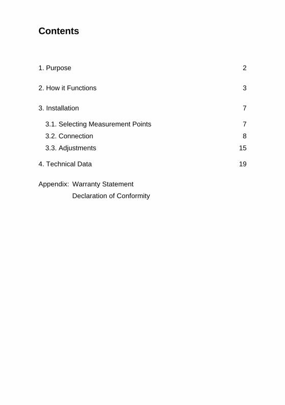
Front View
Alarm
Sensor
Overload
Alarm
Delay0 25
s
2 50mm/s
DC Out-I Out+I Out
Relais
+UsAC OutGND Out
-UsGND InInput
Alarm LEDSensor test LED
Overload LED
Alarm threshold adjustment
Alarm delay adjustment
Relay terminals
RMS outputs
Signal output / positive supply voltage
Sensor input / negative supply voltage
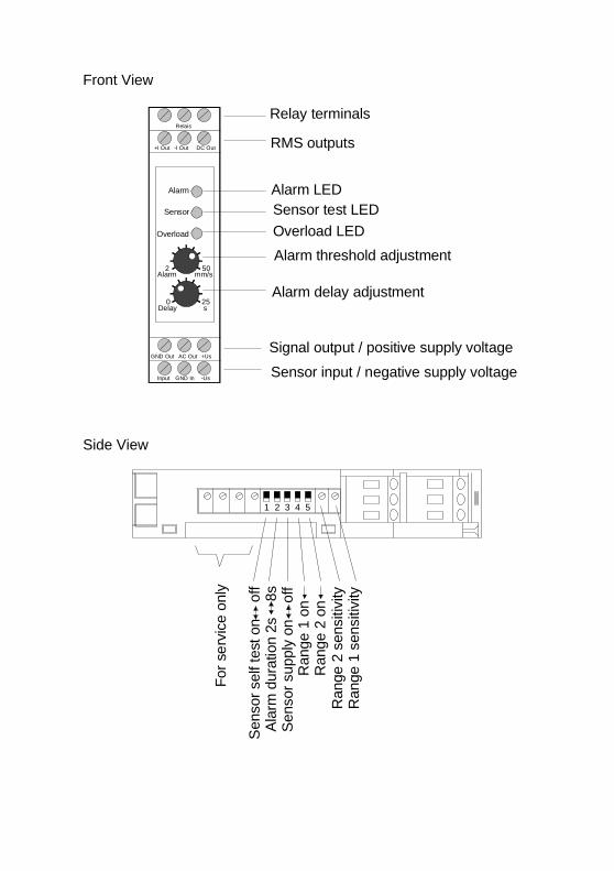
Side View
1 2 3 4 5
Sen
sor
self
test
on
of
fA
larm
dur
atio
n 2s
8
sS
enso
r su
pply
on
of
fR
ange
1 o
n
Ran
ge 2
sen
sitiv
ityR
ange
1 s
ensi
tivity
For
ser
vice
onl
y
Ran
ge 2
on

2
1. Purpose
The M10v is intended for vibration measurement and
monitoring. Its modular concept provides optimum
adaptation to your application.
The M10v delivers standardized vibration quantities
for subsequent processing. Additionally, a relay contact
is included which can be used for alarm indicators or
emergency shut-off of machines.
The M10v measures and monitors vibration velocity
(severity) between 10 and 1000 Hz to DIN/ISO 10816.
It is suited for measurement of low frequency vibration
of machines with rotating parts. These vibrations can
be caused by unbalance due to loose parts, dirty fan
blades, bent parts or worn bearings, for example. Of-
ten, these effects reinforce each other.
Typical applications are vibration monitoring and
predictive maintenance of pumps, compressors, mix-
ers, centrifuges or fans.
The M10v helps the maintenance engineer to predict
and recognize wear of machine parts in time. Thereby,
it may avoid unexpected breakdown, costly repairs and
production loss. The M10v may also contribute to
quality improvement.

3
2. How it Functions
Figure 1 shows the block diagram of the M10v.
High pass Low pass RMS
AC
AC output
Integrator(M10v only)
Sensor
Constant current source
Overloadindicator
Sensorself test Alarm
threshold
Alarmdelay
Alarmduration
RMS DC output
Relay
Opto coupler I
U
4-20mA
Current loopoutput (4 .. 20 mA)
Figure 1: Block Diagram
Sensor The M10v requires a piezoelectric accelerometer with
integrated electronics to ICP standard. We recom-
mend our industrial accelerometers series with insu-
lated base, for example models KS74 and KS80.
The constant current for the integrated sensor elec-
tronics is supplied by the unit and can be activated by a
switch.
Integrator The M10v features an integrator stage converting
vibration acceleration into velocity.
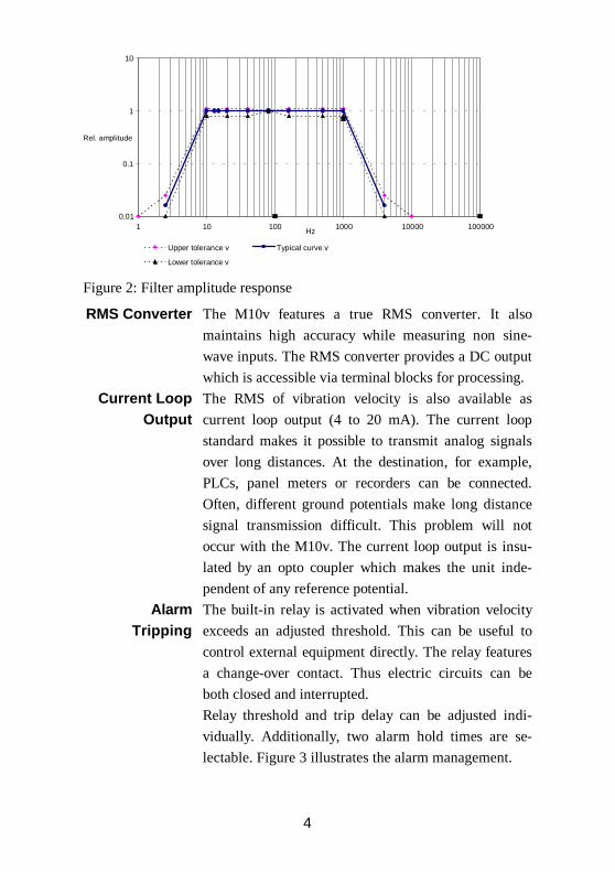
Filter The frequency limits of the built-in 10 to 1000 Hz band
filter are according to ISO 10816.
Figure 2 shows the filter amplitude response including
standardized tolerances.
4
0.01
0.1
1
10
1 10 100 1000 10000 100000 Hz
Rel. amplitude
Upper tolerance v Typical curve v
Lower tolerance v
Figure 2: Filter amplitude response
RMS Converter The M10v features a true RMS converter. It also
maintains high accuracy while measuring non sine-
wave inputs. The RMS converter provides a DC output
which is accessible via terminal blocks for processing.
Current LoopOutput
The RMS of vibration velocity is also available as
current loop output (4 to 20 mA). The current loop
standard makes it possible to transmit analog signals
over long distances. At the destination, for example,
PLCs, panel meters or recorders can be connected.
Often, different ground potentials make long distance
signal transmission difficult. This problem will not
occur with the M10v. The current loop output is insu-
lated by an opto coupler which makes the unit inde-
pendent of any reference potential.
AlarmTripping
The built-in relay is activated when vibration velocity
exceeds an adjusted threshold. This can be useful to
control external equipment directly. The relay features
a change-over contact. Thus electric circuits can be
both closed and interrupted.
Relay threshold and trip delay can be adjusted indi-
vidually. Additionally, two alarm hold times are se-
lectable. Figure 3 illustrates the alarm management.

5
t
Alarmthreshold
Alarm on
Alarm off
td tt d
1 2
3
4
7
6
5
t hon
Figure 3: Alarm management
The upper curve of the diagram shows a typical timegraph of a vibration signal (RMS). The lower curveshows the relay response.At point the adjusted alarm threshold is exceeded.
Now delay time starts. It can be adjusted at the front
panel between 0 and 25 seconds. Since the vibration
level at point has already returned below the alarm
threshold before td is over no alarm will be tripped at
point . Thus short vibration peaks which may occur
due to machine start, shock momentum or electromag-
netic influence will not affect the alarm relay.
At point the alarm threshold is exceeded again and
delay time td starts once more. This time an alarm will
be tripped since the alarm threshold remains exceeded
after td is over at point . The relay will stay activated
until at point vibration level goes below the thresh-
old. Now alarm duration time th starts which can be
selected between 2 and 8 seconds. When th is over the
relay contact returns into its normal position. A de-
fined minimum alarm duration ensures save switching
of external components.

6
Self TestFunctions
It is expected that monitoring equipment has a very
high reliability. Unnoticed faults need to be avoided
and false alarms as well. Maximum reliability of the
M10v is guaranteed by a two-stage self test circuitry:
1. Monitoring of sensor bias voltage recognizes de-
fective accelerometers and broken cables. Defects
are indicated by an yellow LED at the front panel
and on demand via the alarm relay.
2. Power supply failure causes the relay contact to
switch into the alarm position.
OverloadIndicator
The “Overload” LED at the front panel indicates
overload condition of the input stage. When it lights up
the signal has reached 80 % of its maximum range.
However, at this point the output signal is still undis-
torted.
The “Overload” LED only indicates overload of the
input stage. In rare cases it may happen that at the
same time when overload is indicated the RMS output
is in the normal range and the relay does not respond.
This is due to predominant signal components beyond
the filter limits which only affect the input stage but do
not pass the band filter. This problem can only be
avoided by lowering the sensitivity of the used range
(see chapter 3.3).

7
3. Installation
3.1. Selecting Measurement Points
SensorLocation
Before making measurements, you will need to select
suitable attachment points on the machine for the
sensor. Experience in machine condition maintenance
is advantageous for selecting optimum points.
Dynamic forces are normally transmitted via bearings
and their housings into the machine frame. Therefore
bearing housings or points close to bearings are rec-
ommended measuring points. Less suitable are light or
flexible machine parts.
Attachment For best coupling conditions we recommend a stainless
steel disk with mounting thread (for instance Metra
model 229) which can be epoxy glued or welded onto
the machine.
The best way to attach the accelerometer is a stud bolt.
A thin coat of grease on the coupling surfaces will
improve the transmission of high frequencies.
For temporary installations also a magnetic base can be
used (for instance Metra model 008).
Note that scratched, uneven or too small surfaces are
major causes of error, especially at higher frequencies.
EvaluatingLimits
The next step is to determine typical and maximum
allowable values. A simple way is to use standards
specifying limits depending solely on machine power
and foundation type as given for example in ISO
10816. Figure 4 shows different machine categories
with corresponding vibration severity values to ISO
10816.

8
Good
Still Acceptable
Decent
Not Acceptable28
18
11
7
4.5
2.8
1.8
1.1
0.7
0.45
0.28Group S
Small MachineryGroup M
Medium-sizedGroup H
Heavy MachineryGroup T
Turbo Engines
Condition Level:
Vib
ratio
n S
ever
ity i
n m
m/s
Figure 4: Machine condition to ISO 10816
The diagram above is based on the following classifi-cation:• Group S: machine components and motors which
are rigidly connected to the machine body, e.g.electric motors up to 15 kW
• Group M: electric motors 15 to 75 kW withoutspecial foundation, rigidly installed motors or ma-chines up to 300 kW with special foundation
• Group H: big driving and other machinery withrotating parts at rigid and heavy foundation whichis relatively stiff in the measured vibration axis
• Group T: big driving and other machinery withrotating parts and foundation which is relativelypliable in the measured vibration axis, e.g. turbogenerators and gas turbines over 10 MW
3.2. ConnectionMounting The M10v is intended for 35 mm DIN rails. It has been
designed for installation in dry and dust protectedenvironments, preferably in switch cabinets.To attach or remove a module pull out the black leveron the top of the enclosure using a screw driver.

9
TerminalBlocks
All inputs and outputs are accessible via terminal
blocks. They are suited for cable diameters of 0.14 to
4 mm² for single wire and 0.14 to 2.5 mm² for stranded
wire.
PowerSupply
The M10v requires a DC supply voltage between 20
and 28 V which is usually available in industrial envi-
ronments. The maximum current consumption is
50 mA.
Figure 5 shows the power supply connection.
The M10v is protected against false polarization and
overvoltage peaks.
Alarm
Sensor
Overload
Alarm
Delay0 25
s
2 50mm/s
positive (+)negative (-)
frontback
Figure 5: Power supply connection
SensorInput
The M10v is suitable for all kinds of ICP® acceler-
ometers. The built-in constant current supply provides
4 mA supply current. A compliance voltage of >20 V
ensures full dynamic input range independent of the
sensor bias voltage. The constant current source is
activated by pushing the DIP switch “ICP Supply”
towards the “ON” position (Figure 6).

10
1 2 3 4 5
ICP supply on
Figure 6: Activating sensor supply
The input is protected against overvoltage. The input
ground terminal (“GND Input”) is connected to nega-
tive supply voltage.
Ground loops may cause considerable measurement
errors. To avoid these problems preferably acceler-
ometers with insulated base or insulating flanges
should be employed. Thereby the ground potentials of
the machine and the M10v are separated.
The sensor is connected via shielded cable which may
have a length of 100 m or more. Limitations are given
by cable resistance and electromagnetic immunity.
Figure 7 shows the sensor connection.
Alarm
Sensor
Overload
Alarm
Delay0 25
s
2 50mm/s
frontback
GND (Shield)Signal
Figure 7: Sensor connection
Operation oftwo M10v
modules withone Sensor
It is possible to operate two M10v modules with one
mutual sensor. For example, a monitoring system with
2 alarm levels (pre-alarm and main alarm) can be built
in this way (see Figure 8).

11
When two modules are operated with one sensor only
the sensor supply of one module must be activated
(Figure 6).
Alarm
Sensor
Overload
Alarm
Delay0 25
s
2 50mm/s
DC Out-I Out+I Out
Relais
+UsAC OutGND Out
-UsGND InInput
M10v
Sensor
Alarm
Sensor
Overload
Alarm
Delay0 25
s
2 50mm/s
DC Out-I Out+I Out
Relais
+UsAC OutGND Out
-UsGND InInput
M10v
Relay 14-20mA
Relay 24-20mA
Figure 8: Monitoring with two thresholds using one
mutual sensor
The terminals “GND Output”, “DC Output” and “AC
Output” of the two modules are not to be connected.
When the signals “DC Output” and “AC Output” are
required they should be measured referred to terminal
“GND Output” of one of the two modules. Instruments
with symmetric and ground free inputs can be con-
nected to each “GND Output” terminal.
Relay Output The M10v features a change-over relay contact which
transmits the alarm condition. Figure 9 shows the
connection of the relay output. In normal condition
(O.K.) terminal 2 and 3 are connected. In case of
alarm terminal 1 and 2 are short-circuit. In case of
power supply failure the relay switches into alarm
position where it remains until supply voltage is ap-
plied again. By that means power supply failure is
indicated as alarm condition (self test function).
The relay contacts are potential-free and capable of
switching 40 V AC at 2 A. Relays outputs of several
M10v units can be connected in series (logic AND) or
in parallel (logic OR) to bundle and save alarm wires.

12
Alarm
Sensor
Overload
Alarm
Delay0 25
s
2 50mm/s
backfront
1 2 3
Figure 9: Relay output, shown in O.K. position
CurrentLoop
Output
The M10v provides an analog current loop output of
the RMS of vibration velocity between 10 and 1000
Hz. The advantage of a current loop is the possibility to
transmit signals over a long distance without accuracy
loss using cheap cables.
A current of 4 mA corresponds to zero level (0 mm/s
or 0 m/s²). The maximum current of 20 mA is reached
at full scale which is 50 mm/s. The vibration level
corresponding to a measured current is obtained:50 mm/s (Iloop - 4mA)
16 mAv =
The current loop output is a current drain, i.e. a supply
voltage is required in the loop circuit to drive the cur-
rent. Figure 10 illustrates this principle. The internal
current loop circuitry of the M10v requires a minimum
compliance voltage of 14 V between the terminals
“+I Loop” and “-I Loop”. Therefore, the loop supply
voltage should be greater than US > 14 V + UL where
UL is the total voltage drop of all resistors in the circuit
at 20 mA.
13
Measuring resistors
Voltage sourceM10v
+I Loop
-I Loop
+
-
< 14
V
U L
U S
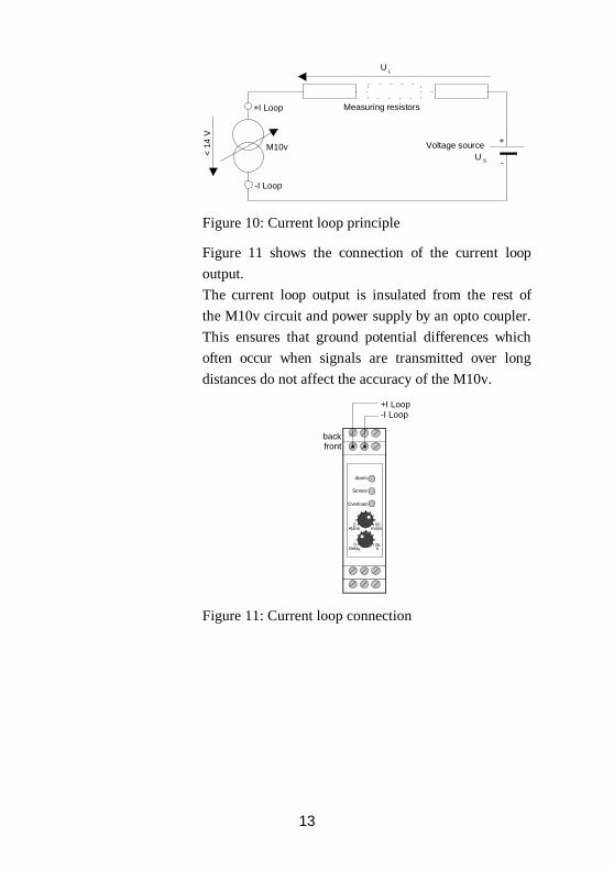
Figure 10: Current loop principle
Figure 11 shows the connection of the current loop
output.
The current loop output is insulated from the rest of
the M10v circuit and power supply by an opto coupler.
This ensures that ground potential differences which
often occur when signals are transmitted over long
distances do not affect the accuracy of the M10v.
Alarm
Sensor
Overload
Alarm
Delay0 25
s
2 50mm/s
backfront
+I Loop-I Loop
Figure 11: Current loop connection

14
DC Output Apart from the current loop output the M10v features a
DC voltage output of the RMS. The DC Output pro-
vides 10 V at full scale representing 50 mm/s.
Consequently, the sensitivity of the DC output of vi-
bration velocity is 200 mV/mms-1.
The reference point of the DC output is not “GND
Input” but an internally generated reference voltage
which is accessible at terminal “GND Output”.
Figure 12 shows the connection.
Caution: The terminal “GND Output” has a DCvoltage of +10 V referred to “GND Input”, i.e. nega-tive supply. Therefore, “GND Input” and “GNDOutput” must never be shorted.
Alarm
Sensor
Overload
Alarm
Delay0 25
s
2 50mm/s
backfront
frontback
GND Output
DC Output
Figure 12: DC output
AC SignalOutput
Often it can be advantageous to know the wide-band
spectral composition of the vibration signal. Observing
the signal by means of scopes or analyzers may yield
information about the source of vibrations. These
measurements can be carried out at the spot or using
recording equipment for subsequent processing. For
that purpose the M10v provides the unfiltered wide-
band acceleration signal of the sensor.
The absolute level at the AC output depends on the
adjusted sensitivity. When the M10v has been cali-
brated the AC output yields 200 mV / g (1 g =
9,81 m/s²).
15
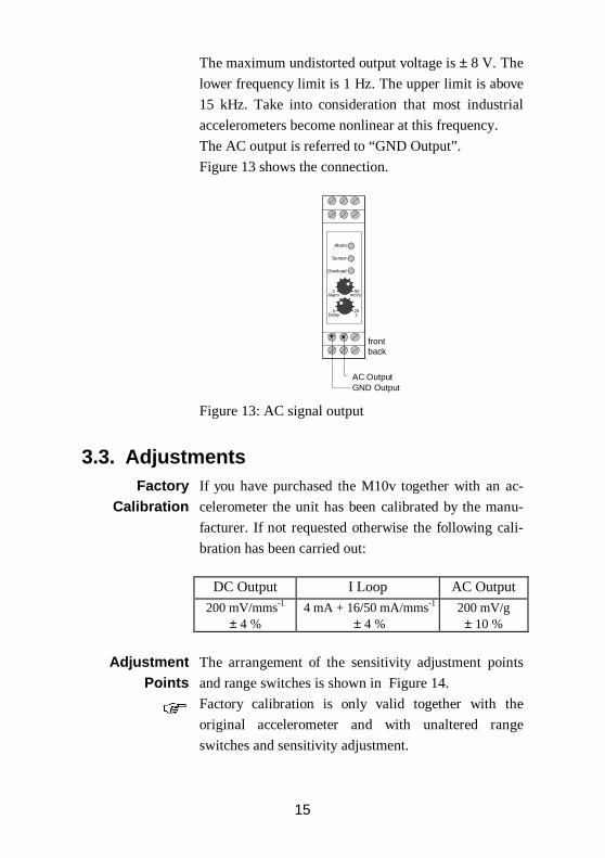
The maximum undistorted output voltage is ± 8 V. The
lower frequency limit is 1 Hz. The upper limit is above
15 kHz. Take into consideration that most industrial
accelerometers become nonlinear at this frequency.
The AC output is referred to “GND Output”.
Figure 13 shows the connection.
Alarm
Sensor
Overload
Alarm
Delay0 25
s
2 50mm/s
frontback
GND OutputAC Output
Figure 13: AC signal output
3.3. AdjustmentsFactory
CalibrationIf you have purchased the M10v together with an ac-
celerometer the unit has been calibrated by the manu-
facturer. If not requested otherwise the following cali-
bration has been carried out:
DC Output I Loop AC Output
200 mV/mms-1
± 4 %4 mA + 16/50 mA/mms-1
± 4 %200 mV/g± 10 %
Adjustment Points
The arrangement of the sensitivity adjustment points
and range switches is shown in Figure 14.
Factory calibration is only valid together with the
original accelerometer and with unaltered range
switches and sensitivity adjustment.

16
1 2 3 4 5
Sensitivity range 1
Sensitivity range 2
Range 2 on
Range 1 on
Figure 14: Adjustment points and range switches
Gain Ranges The M10v has two measuring ranges. The optimum
range depends on the sensitivity of the connected ac-
celerometer.
• Range 1: Transducer sensitivity 0.8 .. 6 mV/ms-2
• Range 2: Transducer sensitivity 5 .. 20 mV/ms-2
Push the DIP switch towards the “ON” position to
activate the corresponding range.
Both ranges must not be activated simultaneously.
SensitivityAdjustment
Sensitivity adjustment is carried out by two trimmers
on the right side of the DIP switches. (Figure 14).
A fast and convenient way to calibrate the M10v is a
vibration calibrator of Metra’s VC series. It supplies a
defined stabilized vibration signal into the acceler-
ometer. The output of the M10v can now be adjusted to
the nominal vibration level.
AlarmAdjustments
The alarm threshold is adjusted by the upper trimmer
at the front panel. The adjustable range is 2 to 50
mm/s.
The scale gives a rough orientation about the adjusted
value.
Alarm delay is adjusted by the lower trimmer. Left
stop corresponds to a delay of 0 s or undelayed alarm
tripping. Right stop is 25 seconds delay.
Alarm duration can be chosen by one of the DIP
switches at the side of the M10. Two durations are
available: 2 and 8 seconds. The adjustment is shown in
Figure 15.

17
1 2 3 4 5
Alarmhaltezeit8s
2s
Figure 15: Alarm duration
SensorSelf Test
The M10v is capable of detecting defective transduc-
ers. For this purpose the sensor bias voltage between
the input terminals is monitored. When the bias volt-
age exceeds a nominal value it means that the constant
current source can not drive sufficient current through
the sensor. Possible causes are a defective sensor or
broken cable. Another reason may be sensor overload.
The sensor detection of the M10v responds at 18 V.
Figure 16 illustrates sensor bias, maximum, and mini-
mum (saturation) output voltage. The bias voltage is
found in the sensor data sheet. The compliance voltage
of the M10v is greater than 20 V.
Maximum sensor output = compliance voltage 20 V
Sensor saturation voltageca. 1 V
Sensor bias=8 .. 12 V (Metra)
negative overload
Sen
sor o
utpu
t sw
ing
0V
positive overload
Figure 16: sensor bias and output swing
A defective sensor is indicated by a yellow LED
“Sensor” at the front panel. If demanded, the sensor
self test function can trigger the alarm relay. For that
purpose push the DIP switch “Self Test” towards the
18
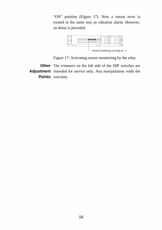
“ON” position (Figure 17). Now a sensor error is
treated in the same way as vibration alarm. However,
no delay is provided.
1 2 3 4 5
Sensor monitoring via relay on
Figure 17: Activating sensor monitoring by the relay
OtherAdjustment
Points
The trimmers on the left side of the DIP switches are
intended for service only. Any manipulation voids the
warranty.

19
4. Technical Data
Ranges(Factory calibration)
0 .. 50 mm/s ± 4 %
Input voltage input, RI > 1 MΩ,AC coupled, ICP® compatible
Sensor supply 3.8 .. 5.6 mA constant current,compliance voltage > 20 VDC,activated by DIP switch
Suitable sensors ICP® compatible accelerometers,sensitivity:
range 1: 0.8 .. 6 mV/ms-2
range 2: 5 .. 20 mV/ms-2
Band filter 10 .. 1000 Hz (-3 dB), two poles
Relay output 40 V AC / 2A, potential free,change-over contact
Relay threshold range 2 .. 50 mm/s
Relay delay 0 .. 25 s
Relay hold duration 2 or 8 s
Current loop output 4 .. 20 mA, current drain, insulated,loop supply voltage > 14 V
DC output 0 .. 10 VDC true RMS of vibration(with > 24 VDC supply voltage)
Wide-band output acceleration signal, ûOUT = ± 8 V,1 .. 15 000 Hz, impedance 100 Ω,sensitivity when factory calibrated:200 mV/g
Sensor monitoring LED, via relay alternatively,threshold: >18 V sensor bias
Overload indicator LED, at approx. 80 % of full scale output
Power supply 20 .. 28 VDC / 50 mA
Operating temperature range -10 .. 55 °Crelative humidity < 95 %, no condensation
Dimensions (w x h x d) 22 x 76 x 111 mm³
Weight approximately 120 g

20
Limited Warranty
Metra warrants for a period of
24 months
that its products will be free from defects
in material or workmanship and shall conform to the specifications
current at the time of shipment.
The warranty period starts with the date of invoice.
The customer must provide the dated bill of sale as evidence.
The warranty period ends after 24 months.
Repairs do not extend the warranty period.
This limited warranty covers only defects which arise as a result
of normal use according to the instruction manual.
Metra’s responsibility under this warranty does not apply to any
improper or inadequate maintenance or modification
and operation outside the product’s specifications.
Shipment to Metra will be paid by the customer.
The repaired or replaced product will be sent back at Metra’s expense.

21
Declaration of Conformity
Product: Modular Vibration Monitor
Model: M10v
It is hereby certified that
the above mentioned product
complies with the demands
pursuant to the following standards:
• EN 50081
• EN 50082
Responsible for the manufacturer
Metra Mess- und Frequenztechnik
Meissner Str. 58
D-01445 Radebeul
Manfred Weber
Radebeul, 2nd of October, 1998