Embed Size (px)
Citation preview
PUMP CONTROLS
PNEUMERCATORLiquid Level Control Systems
INSTRUCTION MANUAL
PC1000 SERIES
© COPYRIGHT 2017 PNEUMERCATOR CO., INC. 1785 EXPRESSWAY DRIVE NORTH
HAUPPAUGE, NY 11788
(631) 293-8450 Phone (631) 293-8533 Fax
(800) 209-7858 Support www.pneumercator.com
PC100x Instruction Manual - 2017-07-16.docx July 16, 2017
DRAWING NO. 20147 REV. N/C

PC1000 INSTRUCTION MANUAL TABLE OF CONTENTS
TABLE OF CONTENTSPage
SAFETY INFORMATION ........................................................................................ 5
Section 1 PRODUCT DESCRIPTION 1.1 General System Overview ...................................................................................... 6 1.2 Control Console Description ................................................................................... 7 1.3 Liquid Sensor Description ..................................................................................... 10
Section 2 INSTALLATION DETAILS
2.1 Installation Checklist ............................................................................................. 11 2.2 Control Console Installation .................................................................................. 12 2.3 Sensor Installation ................................................................................................ 13
Section 3 WIRING INSTALLATION AND DIAGRAMS 3.1 PC Board Setup and Layout ................................................................................. 14 3.2 System Wiring ....................................................................................................... 16 3.3 Sensor Map/System Setup ................................................................................... 22 3.4 Installation as a Remote Alarm Panel ................................................................... 22
Section 4 OPERATION
4.1 General ................................................................................................................. 23 4.2 Horn Control ......................................................................................................... 23
Section 5 TROUBLESHOOTING
5.1 General ................................................................................................................. 24 5.2 Spare Parts List .................................................................................................... 24
Section 6 MAINTENANCE/TESTING
6.1 Console ................................................................................................................. 25 6.2 Sensors ................................................................................................................. 25

PC1000 INSTRUCTION MANUAL SAFETY
PAGE 5
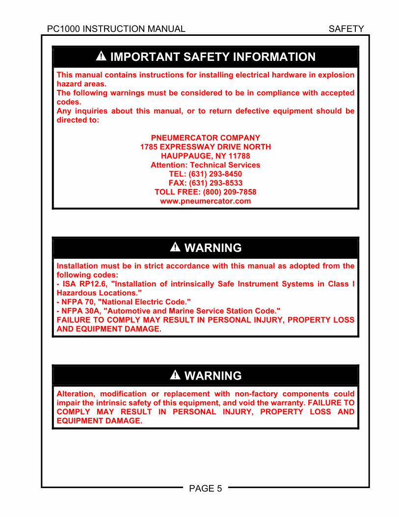
IMPORTANT SAFETY INFORMATION
This manual contains instructions for installing electrical hardware in explosion hazard areas. The following warnings must be considered to be in compliance with accepted codes. Any inquiries about this manual, or to return defective equipment should be directed to:
PNEUMERCATOR COMPANY 1785 EXPRESSWAY DRIVE NORTH
HAUPPAUGE, NY 11788 Attention: Technical Services
TEL: (631) 293-8450 FAX: (631) 293-8533
TOLL FREE: (800) 209-7858 www.pneumercator.com
WARNING
Installation must be in strict accordance with this manual as adopted from the following codes: - ISA RP12.6, "Installation of intrinsically Safe Instrument Systems in Class I Hazardous Locations." - NFPA 70, "National Electric Code." - NFPA 30A, "Automotive and Marine Service Station Code." FAILURE TO COMPLY MAY RESULT IN PERSONAL INJURY, PROPERTY LOSS AND EQUIPMENT DAMAGE.
WARNING
Alteration, modification or replacement with non-factory components could impair the intrinsic safety of this equipment, and void the warranty. FAILURE TO COMPLY MAY RESULT IN PERSONAL INJURY, PROPERTY LOSS AND EQUIPMENT DAMAGE.
PC1000 INSTRUCTION MANUAL PRODUCT DESCRIPTION
PAGE 6
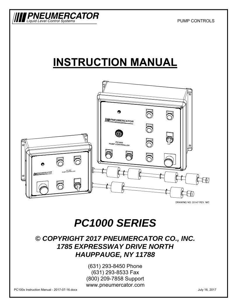
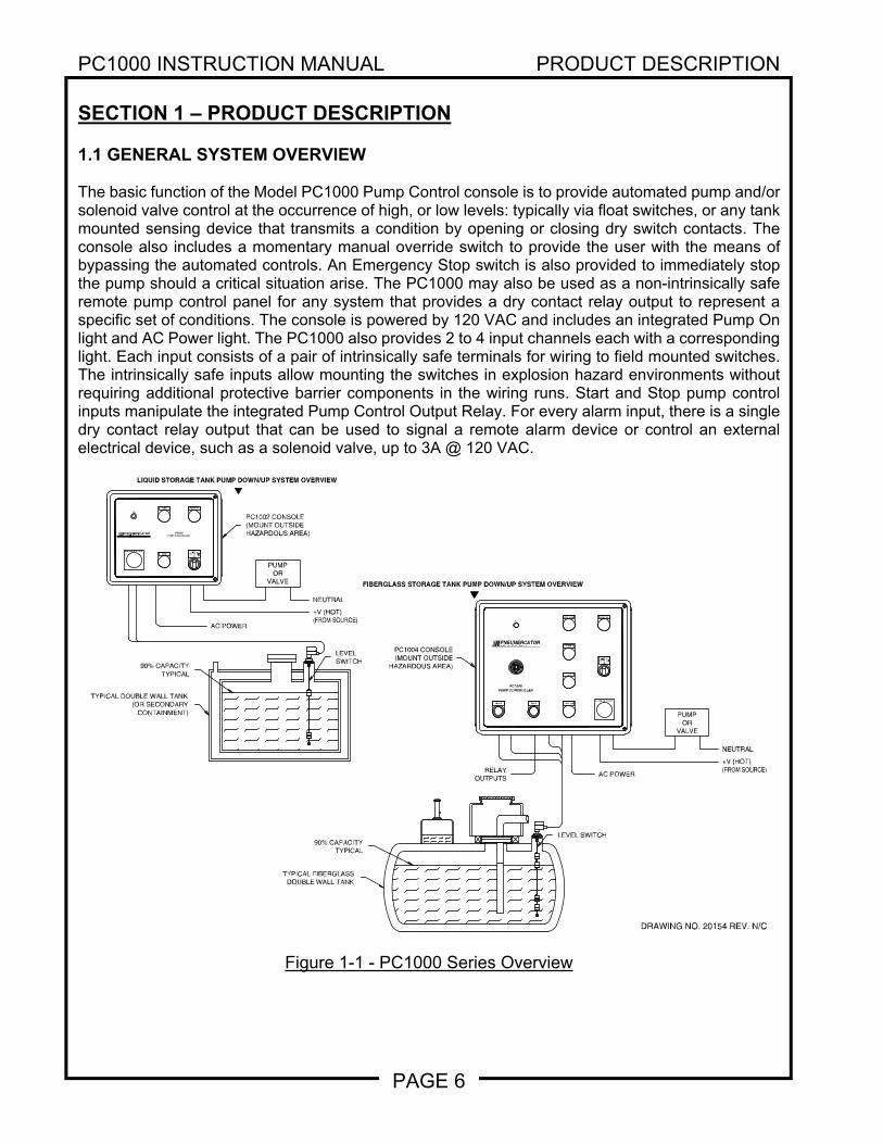
SECTION 1 – PRODUCT DESCRIPTION 1.1 GENERAL SYSTEM OVERVIEW The basic function of the Model PC1000 Pump Control console is to provide automated pump and/or solenoid valve control at the occurrence of high, or low levels: typically via float switches, or any tank mounted sensing device that transmits a condition by opening or closing dry switch contacts. The console also includes a momentary manual override switch to provide the user with the means of bypassing the automated controls. An Emergency Stop switch is also provided to immediately stop the pump should a critical situation arise. The PC1000 may also be used as a non-intrinsically safe remote pump control panel for any system that provides a dry contact relay output to represent a specific set of conditions. The console is powered by 120 VAC and includes an integrated Pump On light and AC Power light. The PC1000 also provides 2 to 4 input channels each with a corresponding light. Each input consists of a pair of intrinsically safe terminals for wiring to field mounted switches. The intrinsically safe inputs allow mounting the switches in explosion hazard environments without requiring additional protective barrier components in the wiring runs. Start and Stop pump control inputs manipulate the integrated Pump Control Output Relay. For every alarm input, there is a single dry contact relay output that can be used to signal a remote alarm device or control an external electrical device, such as a solenoid valve, up to 3A @ 120 VAC.
Figure 1-1 - PC1000 Series Overview
DRAWING NO. 20154 REV. N/C
AC POWER
LIQUID STORAGE TANK PUMP DOWN/UP SYSTEM OVERVIEW
PC1002 CONSOLE(MOUNT OUTSIDEHAZARDOUS AREA)
90% CAPACITYTYPICAL
LEVELSWITCH
FIBERGLASS STORAGE TANK PUMP DOWN/UP SYSTEM OVERVIEW
LEVEL SWITCH
TYPICAL DOUBLE WALL TANK(OR SECONDARY
CONTAINMENT)
90% CAPACITYTYPICAL
TYPICAL FIBERGLASSDOUBLE WALL TANK
RELAYOUTPUTS AC POWER
PC1004 CONSOLE(MOUNT OUTSIDE
HAZARDOUS AREA)
HIGH
EMERGENCY STOP
LOW
PUMP ON
AC
PC1000
PUMP CONTROLLERLiquid Level Control SystemsPNEUMERCATOR
NO .NAMA
OFFMAN.UTO
CRIT HIGH
HIGH
LOW
CRIT LOW
EMERGENCY STOP
PUMP ON
RESET TEST
AC
PC1000PUMP CONTROLLER
Liquid Level Control Systems
PNEUMERCATOR
NO .NAMA
OFFMAN.
UTO
PUMPOR
VALVE
NEUTRAL
+V (HOT)(FROM SOURCE)
PUMPOR
VALVE
NEUTRAL
+V (HOT)(FROM SOURCE
PC1000 INSTRUCTION MANUAL PRODUCT DESCRIPTION
PAGE 7
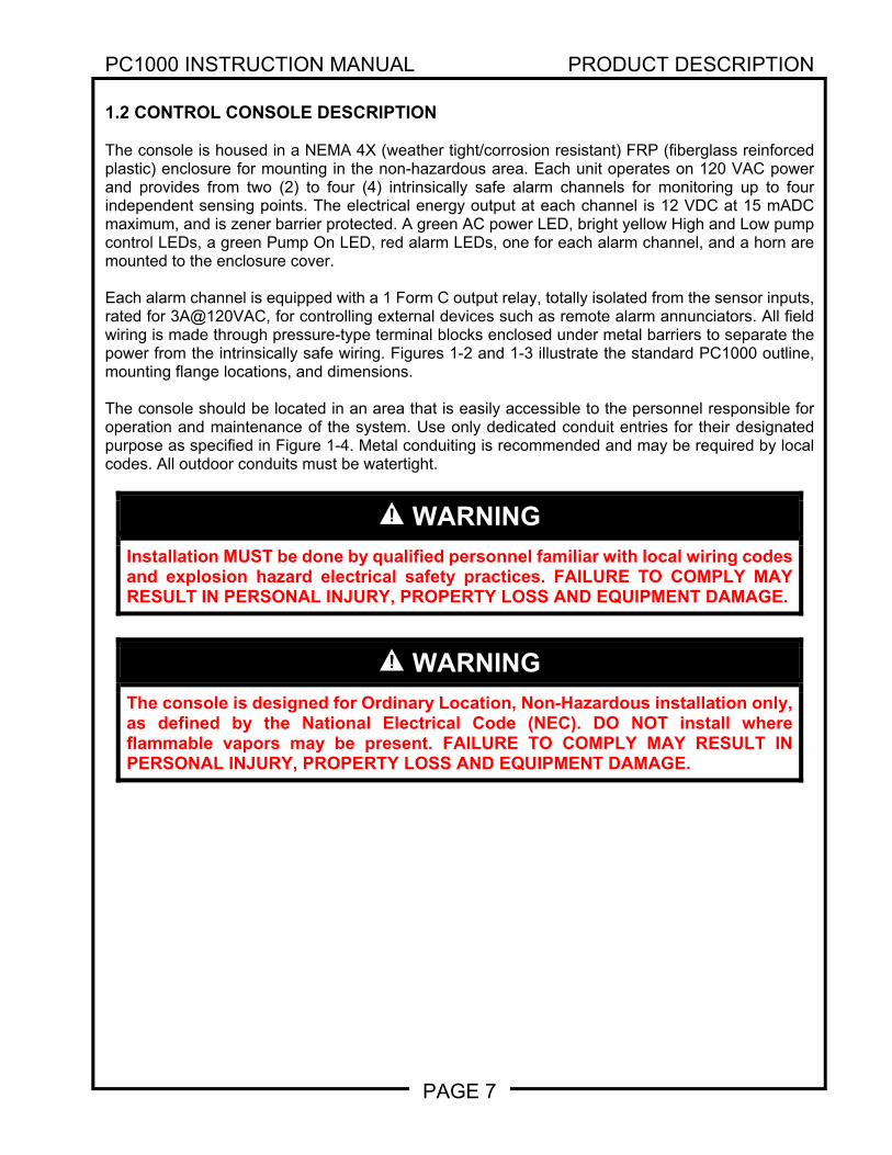
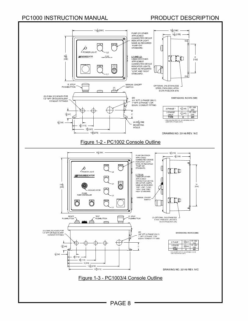
1.2 CONTROL CONSOLE DESCRIPTION The console is housed in a NEMA 4X (weather tight/corrosion resistant) FRP (fiberglass reinforced plastic) enclosure for mounting in the non-hazardous area. Each unit operates on 120 VAC power and provides from two (2) to four (4) intrinsically safe alarm channels for monitoring up to four independent sensing points. The electrical energy output at each channel is 12 VDC at 15 mADC maximum, and is zener barrier protected. A green AC power LED, bright yellow High and Low pump control LEDs, a green Pump On LED, red alarm LEDs, one for each alarm channel, and a horn are mounted to the enclosure cover. Each alarm channel is equipped with a 1 Form C output relay, totally isolated from the sensor inputs, rated for 3A@120VAC, for controlling external devices such as remote alarm annunciators. All field wiring is made through pressure-type terminal blocks enclosed under metal barriers to separate the power from the intrinsically safe wiring. Figures 1-2 and 1-3 illustrate the standard PC1000 outline, mounting flange locations, and dimensions. The console should be located in an area that is easily accessible to the personnel responsible for operation and maintenance of the system. Use only dedicated conduit entries for their designated purpose as specified in Figure 1-4. Metal conduiting is recommended and may be required by local codes. All outdoor conduits must be watertight.
WARNING
Installation MUST be done by qualified personnel familiar with local wiring codes and explosion hazard electrical safety practices. FAILURE TO COMPLY MAY RESULT IN PERSONAL INJURY, PROPERTY LOSS AND EQUIPMENT DAMAGE.
WARNING
The console is designed for Ordinary Location, Non-Hazardous installation only, as defined by the National Electrical Code (NEC). DO NOT install where flammable vapors may be present. FAILURE TO COMPLY MAY RESULT IN PERSONAL INJURY, PROPERTY LOSS AND EQUIPMENT DAMAGE.
PC1000 INSTRUCTION MANUAL PRODUCT DESCRIPTION
PAGE 8
Figure 1-2 - PC1002 Console Outline
Figure 1-3 - PC1003/4 Console Outline
DRAWING NO. 20148 REV. N/C
DIMENSIONS: INCHES [MM]
POWER LIGHT
MANUAL ON/OFFSWITCH
E. STOPPUSHBUTTON
(2) Ø.844 [21] HOLES FOR1/2" NPT OR EQUIVALENT
CONDUIT FITTINGS
11 716 [291]
6 [153]
9 516
[236]
7 516 [186]
5 716 [138]
158 [41]
218 [54]
438 [111]
734 [197]
1034 [272]
OPTIONAL 316 STAINLESSSTEEL PADLOCK LATCH
Ø.375 PADLOCK EYE
HIGH
EMERGENCY STOPLOW
PUMP ON
AC
PC1000PUMP CONTROLLERLiquid Level Control Systems
PNEUMERCATOR
NO .
NAMA
OF F
MA
N .
UTO
PUMP OR OTHERAPPLICABLECONNECTED DEVICEINDICATOR LIGHT.NAME AS REQUIRED"PUMP ON"STANDARD.
L2
L1 AND L2:LS600 OR OTHERAPPLICABLECONNECTED DEVICEINDICATOR LIGHTS.NAME AS REQUIRED"LOW" AND "HIGH"STANDARD.L1
(4) Ø516 [Ø8]
MOUNTINGHOLES
C
ØD3/4" NPT (2-PHASE ONLY)1" NPT (3-PHASE *) OREQUIV. CONDUIT FITTING
TYPE C ØD
1 58 [41] Ø1.093
[28]2-PHASE
ONLY
1 34 [44] Ø1.344
[34]3-PHASE *
* ENCLOSURES WITH Ø1.344 OPENING CAN BE USED FOR 2-PHASE UNITS.
DRAWING NO. 20149 REV. N/C
CRIT HIGH
HIGH
LOW
CRIT LOWEMERGENCY STOP
PUMP ON
RESET TEST
AC
PC1000PUMP CONTROLLER
Liquid Level Control SystemsPNEUMERCATOR
NO .N
AMA
O
FFMA
N .
UTO
POWER LIGHT
L2
L1
L3
L4
PUMP OR OTHERAPPLICABLECONNECTED DEVICEINDICATOR LIGHT.NAME AS REQUIRED"PUMP ON"STANDARD.
L1 TO L4:LS600 OR OTHERAPPLICABLECONNECTED DEVICEINDICATOR LIGHTS.NAME AS REQUIRED"CRIT LOW", "LOW","HIGH" AND "CRITHIGH" STANDARD.
E. STOPPUSHBUTTON
RESETPUSHBUTTON
TESTPUSHBUTTON
ANNUNCIATOR
13 516
[338]
1512 [394] 81
2 [216]
658 [168]
10 [254]
(2) OPTIONAL 316 STAINLESSSTEEL PADLOCK LATCHES
Ø.375 PADLOCK EYE
C
ØD3/4" NPT (2-PHASE ONLY)1" NPT (3-PHASE *) OREQUIV. CONDUIT FITTING
(4) Ø.844 [21] HOLES FOR1/2" NPT OR EQUIVALENT
CONDUIT FITTINGS
11116 [44]
218 [54]
438 [112]
634 [172]
9 [229]
12 716 [316]
1434 [375]
MANUAL ON/OFFSWITCH
DIMENSIONS: INCHES [MM]
TYPE C ØD
1 1116 [44]
Ø1.093[28]
2-PHASEONLY
1 1316 [47]
Ø1.344[34]3-PHASE *
* ENCLOSURES WITH Ø1.344 OPENING CAN BE USED FOR 2-PHASE UNITS.
PC1000 INSTRUCTION MANUAL PRODUCT DESCRIPTION
PAGE 9
WARNING
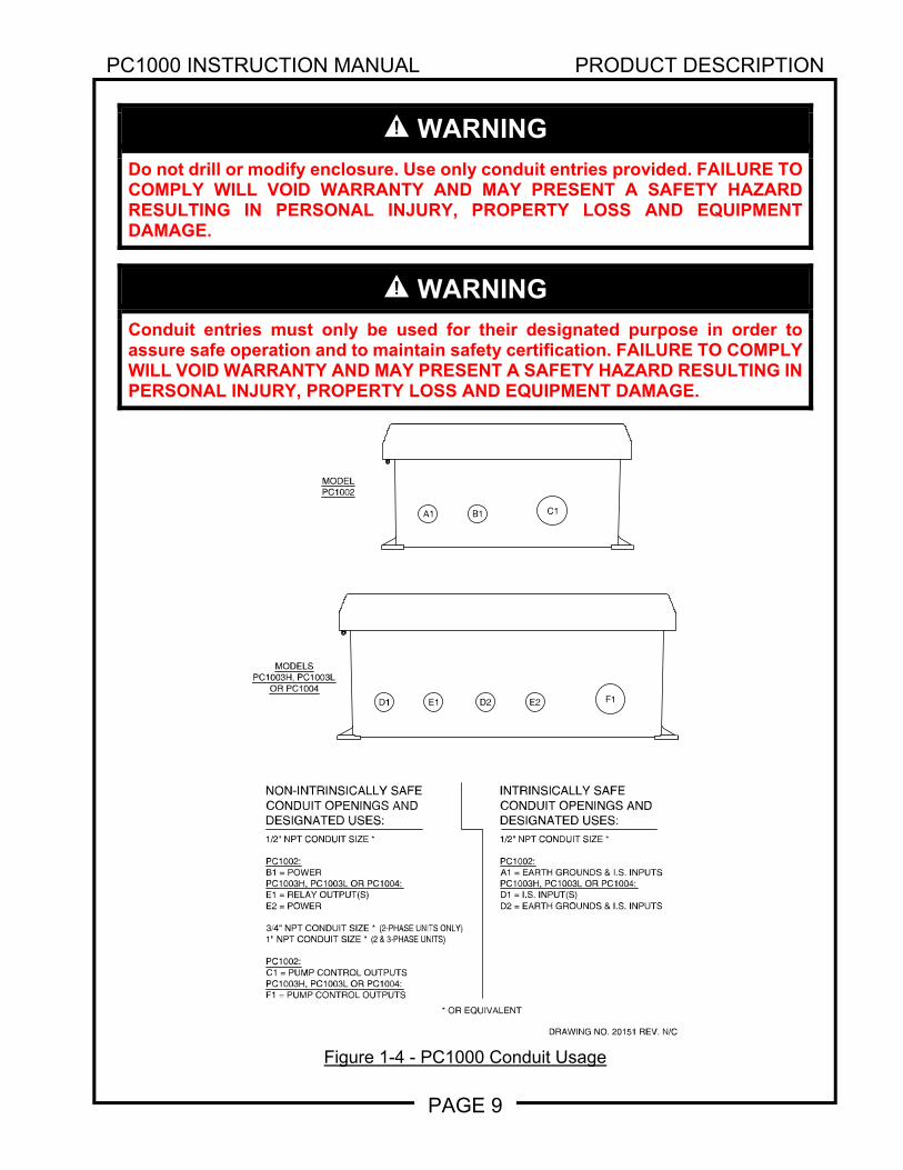
Do not drill or modify enclosure. Use only conduit entries provided. FAILURE TO COMPLY WILL VOID WARRANTY AND MAY PRESENT A SAFETY HAZARD RESULTING IN PERSONAL INJURY, PROPERTY LOSS AND EQUIPMENT DAMAGE.
WARNING
Conduit entries must only be used for their designated purpose in order to assure safe operation and to maintain safety certification. FAILURE TO COMPLY WILL VOID WARRANTY AND MAY PRESENT A SAFETY HAZARD RESULTING IN PERSONAL INJURY, PROPERTY LOSS AND EQUIPMENT DAMAGE.
Figure 1-4 - PC1000 Conduit Usage DRAWING NO. 20151 REV. N/C
NON-INTRINSICALLY SAFECONDUIT OPENINGS ANDDESIGNATED USES:1/2" NPT CONDUIT SIZE *
PC1002:B1 = POWERPC1003H, PC1003L OR PC1004:E1 = RELAY OUTPUT(S)E2 = POWER
3/4" NPT CONDUIT SIZE * (2-PHASE UNITS ONLY)1" NPT CONDUIT SIZE * (2 & 3-PHASE UNITS)
PC1002:C1 = PUMP CONTROL OUTPUTSPC1003H, PC1003L OR PC1004:F1 = PUMP CONTROL OUTPUTS
1/2" NPT CONDUIT SIZE *
PC1002:A1 = EARTH GROUNDS & I.S. INPUTSPC1003H, PC1003L OR PC1004:D1 = I.S. INPUT(S)D2 = EARTH GROUNDS & I.S. INPUTS
INTRINSICALLY SAFECONDUIT OPENINGS ANDDESIGNATED USES:
* OR EQUIVALENT
MODELSPC1003H, PC1003L
OR PC1004
MODELPC1002
A1 B1 C1
D1 E1 D2 E2 F1
PC1000 INSTRUCTION MANUAL PRODUCT DESCRIPTION
PAGE 10
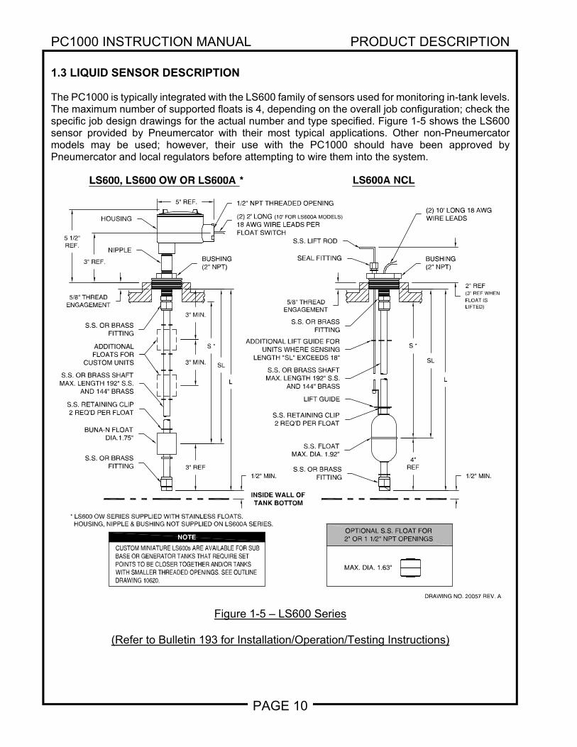
1.3 LIQUID SENSOR DESCRIPTION The PC1000 is typically integrated with the LS600 family of sensors used for monitoring in-tank levels. The maximum number of supported floats is 4, depending on the overall job configuration; check the specific job design drawings for the actual number and type specified. Figure 1-5 shows the LS600 sensor provided by Pneumercator with their most typical applications. Other non-Pneumercator models may be used; however, their use with the PC1000 should have been approved by Pneumercator and local regulators before attempting to wire them into the system.
Figure 1-5 – LS600 Series
(Refer to Bulletin 193 for Installation/Operation/Testing Instructions)
DRAWING NO. 20057 REV. A
SL
1/2" NPT THREADED OPENING
MAX. DIA. 1.63"
3" REF
S.S. RETAINING CLIP2 REQ'D PER FLOAT
LIFT GUIDE
SL
ADDITIONAL LIFT GUIDE FORUNITS WHERE SENSING
LENGTH "SL" EXCEEDS 18"
2" REF(3" REF WHENFLOAT ISLIFTED)
5" REF.
5 1/2"REF.
S.S. OR BRASSFITTING
S.S. FLOATMAX. DIA. 1.92"
S.S. RETAINING CLIP2 REQ'D PER FLOAT
S.S. OR BRASSFITTING
S.S. OR BRASSFITTING
S.S. OR BRASSFITTING
(2) 2' LONG (10' FOR LS600A MODELS)18 AWG WIRE LEADS PERFLOAT SWITCH
(2) 10' LONG 18 AWGWIRE LEADS
ADDITIONALFLOATS FOR
CUSTOM UNITSS.S. OR BRASS SHAFT
MAX. LENGTH 192" S.S.AND 144" BRASS
SEAL FITTING
S.S. LIFT ROD
BUSHING(2" NPT)
LS600A NCLLS600, LS600 OW OR LS600A *
BUNA-N FLOATDIA.1.75"
S.S. OR BRASS SHAFTMAX. LENGTH 192" S.S.
AND 144" BRASS
BUSHING(2" NPT)
NIPPLE
HOUSING
3" MIN.
3" MIN.
1/2" MIN.
4"REF
1/2" MIN.
OPTIONAL S.S. FLOAT FOR2" OR 1 1/2" NPT OPENINGS
INSIDE WALL OFTANK BOTTOM
L L
S *
5/8" THREADENGAGEMENT
S *
5/8" THREADENGAGEMENT
3" REF.
* LS600 OW SERIES SUPPLIED WITH STAINLESS FLOATS.HOUSING, NIPPLE & BUSHING NOT SUPPLIED ON LS600A SERIES.
CUSTOM MINIATURE LS600s ARE AVAILABLE FOR SUBBASE OR GENERATOR TANKS THAT REQUIRE SETPOINTS TO BE CLOSER TOGETHER AND/OR TANKSWITH SMALLER THREADED OPENINGS. SEE OUTLINEDRAWING 10620.
NOTE
PC1000 INSTRUCTION MANUAL INSTALLATION DETAILS
PAGE 11
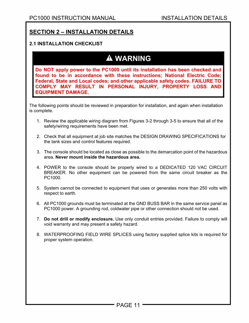
SECTION 2 – INSTALLATION DETAILS 2.1 INSTALLATION CHECKLIST
WARNING
Do NOT apply power to the PC1000 until its installation has been checked and found to be in accordance with these instructions; National Electric Code; Federal, State and Local codes; and other applicable safety codes. FAILURE TO COMPLY MAY RESULT IN PERSONAL INJURY, PROPERTY LOSS AND EQUIPMENT DAMAGE.
The following points should be reviewed in preparation for installation, and again when installation is complete.
1. Review the applicable wiring diagram from Figures 3-2 through 3-5 to ensure that all of the safety/wiring requirements have been met.
2. Check that all equipment at job site matches the DESIGN DRAWING SPECIFICATIONS for
the tank sizes and control features required.
3. The console should be located as close as possible to the demarcation point of the hazardous area. Never mount inside the hazardous area.
4. POWER to the console should be properly wired to a DEDICATED 120 VAC CIRCUIT
BREAKER. No other equipment can be powered from the same circuit breaker as the PC1000.
5. System cannot be connected to equipment that uses or generates more than 250 volts with
respect to earth.
6. All PC1000 grounds must be terminated at the GND BUSS BAR in the same service panel as PC1000 power. A grounding rod, coldwater pipe or other connection should not be used.
7. Do not drill or modify enclosure. Use only conduit entries provided. Failure to comply will
void warranty and may present a safety hazard.
8. WATERPROOFING FIELD WIRE SPLICES using factory supplied splice kits is required for proper system operation.
PC1000 INSTRUCTION MANUAL INSTALLATION DETAILS
PAGE 12
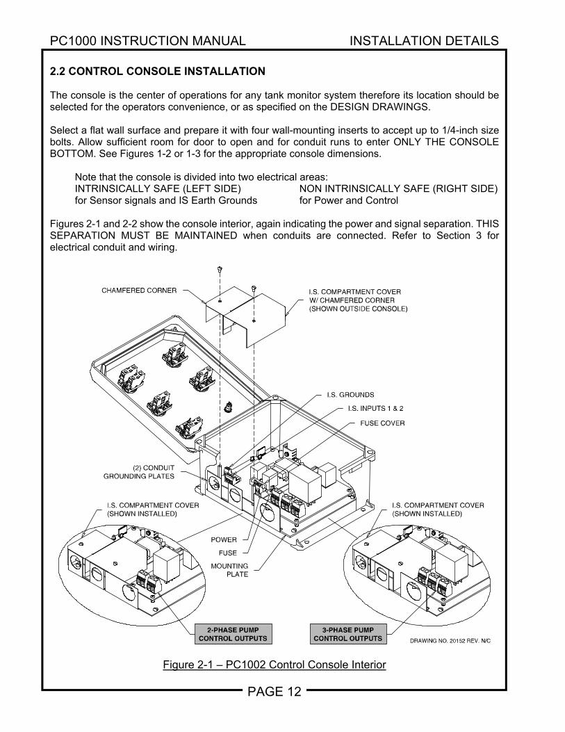
2.2 CONTROL CONSOLE INSTALLATION The console is the center of operations for any tank monitor system therefore its location should be selected for the operators convenience, or as specified on the DESIGN DRAWINGS. Select a flat wall surface and prepare it with four wall-mounting inserts to accept up to 1/4-inch size bolts. Allow sufficient room for door to open and for conduit runs to enter ONLY THE CONSOLE BOTTOM. See Figures 1-2 or 1-3 for the appropriate console dimensions.
Note that the console is divided into two electrical areas: INTRINSICALLY SAFE (LEFT SIDE) NON INTRINSICALLY SAFE (RIGHT SIDE) for Sensor signals and IS Earth Grounds for Power and Control
Figures 2-1 and 2-2 show the console interior, again indicating the power and signal separation. THIS SEPARATION MUST BE MAINTAINED when conduits are connected. Refer to Section 3 for electrical conduit and wiring.
Figure 2-1 – PC1002 Control Console Interior
DRAWING NO. 20152 REV. N/C
CHAMFERED CORNER I.S. COMPARTMENT COVERW/ CHAMFERED CORNER(SHOWN OUTSIDE CONSOLE)
I.S. GROUNDS
I.S. INPUTS 1 & 2
(2) CONDUITGROUNDING PLATES
POWER
I.S. COMPARTMENT COVER(SHOWN INSTALLED)
FUSE COVER
MOUNTINGPLATE
FUSE
I.S. COMPARTMENT COVER(SHOWN INSTALLED)
2-PHASE PUMPCONTROL OUTPUTS
3-PHASE PUMPCONTROL OUTPUTS
PC1000 INSTRUCTION MANUAL INSTALLATION DETAILS
PAGE 13
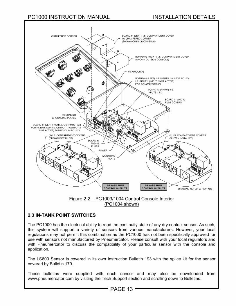
Figure 2-2 – PC1003/1004 Control Console Interior (PC1004 shown)
2.3 IN-TANK POINT SWITCHES The PC1000 has the electrical ability to read the continuity state of any dry contact sensor. As such, this system will support a variety of sensors from various manufacturers. However, your local regulations may not permit this combination as the PC1000 has not been specifically approved for use with sensors not manufactured by Pneumercator. Please consult with your local regulators and with Pneumercator to discuss the compatibility of your particular sensor with the console and application. The LS600 Sensor is covered in its own Instruction Bulletin 193 with the splice kit for the sensor covered by Bulletin 179. These bulletins were supplied with each sensor and may also be downloaded from www.pneumercator.com by visiting the Tech Support section and scrolling down to Bulletins.
DRAWING NO. 20153 REV. N/C
CHAMFERED CORNER BOARD #1 (LEFT): I.S. COMPARTMENT COVERW/ CHAMFERED CORNER(SHOWN OUTSIDE CONSOLE)
I.S. GROUNDS
BOARD #1 (LEFT): I.S. INPUTS 1 & 2 FOR PC1004.I.S. INPUT 1 (INPUT 2 NOT ACTIVE)FOR PC1003H/PC1003L
BOARD #1 (LEFT): NON I.S. OUTPUTS 1 & 2FOR PC1004. NON I.S. OUTPUT 1 (OUTPUT 2
NOT ACTIVE) FOR PC1003H/PC1003L
(3) CONDUITGROUNDING PLATES
POWER
(2) I.S. COMPARTMENT COVERS(SHOWN INSTALLED)
BOARD #2 (RIGHT): I.S.INPUTS 1 & 2
BOARD #1 AND #2FUSE COVERS
BOARD #2 (RIGHT): I.S. COMPARTMENT COVER(SHOWN OUTSIDE CONSOLE)
MOUNTINGPLATE
BOARD #1AND #2FUSES
2-PHASE PUMPCONTROL OUTPUTS
3-PHASE PUMPCONTROL OUTPUTS
(2) I.S. COMPARTMENT COVERS(SHOWN INSTALLED)
PC1000 INSTRUCTION MANUAL WIRING
PAGE 14
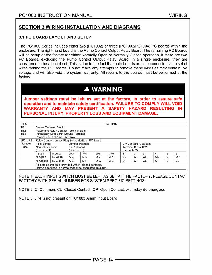
SECTION 3 WIRING INSTALLATION AND DIAGRAMS 3.1 PC BOARD LAYOUT AND SETUP The PC1000 Series includes either two (PC1002) or three (PC1003/PC1004) PC boards within the enclosure. The right-hand board is the Pump Control Output Relay Board. The remaining PC Boards will be setup at the factory for either Normally Open or Normally Closed operation. If there are two PC Boards, excluding the Pump Control Output Relay Board, in a single enclosure, they are considered to be a board set. This is due to the fact that both boards are interconnected via a set of wires behind the PC Boards. Do not make any attempts to remove these wires as they contain live voltage and will also void the system warranty. All repairs to the boards must be performed at the factory.
WARNING
Jumper settings must be left as set at the factory, in order to assure safe operation and to maintain safety certification. FAILURE TO COMPLY WILL VOID WARRANTY AND MAY PRESENT A SAFETY HAZARD RESULTING IN PERSONAL INJURY, PROPERTY LOSS AND EQUIPMENT DAMAGE.
ITEM FUNCTIONTB1 TB2 TB3 F1
Sensor Terminal Block Power and Relay Contact Terminal Block Intrinsically Safe Earth Ground Terminal Power Fuse: 0.1 Amp, Slo-Blow
JP3- JP6 (Jumper Plugs)
Relay Control Jumper Plug Schedule/Each PC BoardField Sensor Normal Condition (See note 1)
Jumper Position on PC Board (See note 3)
Dry Contacts Output at Terminal Block TB2 (See note 2)
Input 1 Input 2 JP3 JP4 JP5 JP6 1 2 3 4 5 6N. Open N. Open A-B D-E U-V X-Y CL C OP CL C OP
N. Closed N. Closed A-C D-F U-W X-Z OP C CL OP C CL
Failsafe operation is provided with N. closed contacts. Relays energized in normal mode; de-energized on alarm.
NOTE 1: EACH INPUT SWITCH MUST BE LEFT AS SET AT THE FACTORY. PLEASE CONTACT FACTORY WITH SERIAL NUMBER FOR SYSTEM SPECIFIC SETTINGS. NOTE 2: C=Common, CL=Closed Contact, OP=Open Contact; with relay de-energized. NOTE 3: JP4 is not present on PC1003 Alarm Input Board
PC1000 INSTRUCTION MANUAL WIRING
PAGE 15
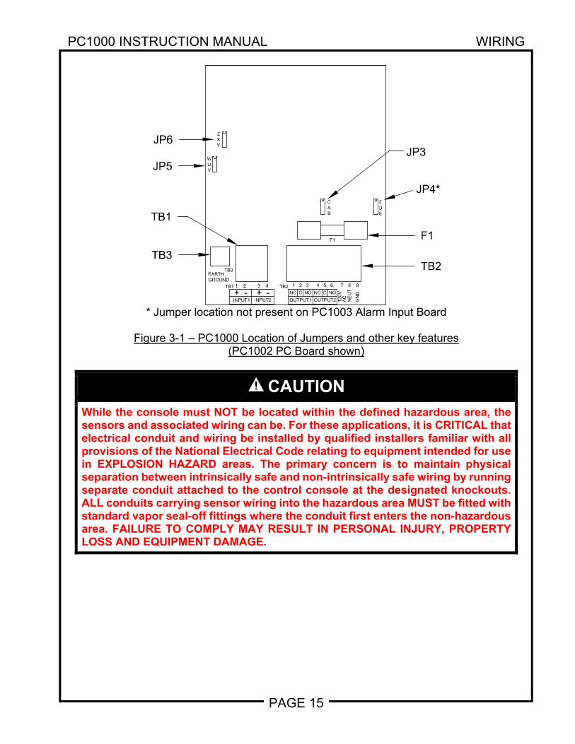
* Jumper location not present on PC1003 Alarm Input Board
Figure 3-1 – PC1000 Location of Jumpers and other key features
(PC1002 PC Board shown)
CAUTION
While the console must NOT be located within the defined hazardous area, the sensors and associated wiring can be. For these applications, it is CRITICAL that electrical conduit and wiring be installed by qualified installers familiar with all provisions of the National Electrical Code relating to equipment intended for use in EXPLOSION HAZARD areas. The primary concern is to maintain physical separation between intrinsically safe and non-intrinsically safe wiring by running separate conduit attached to the control console at the designated knockouts. ALL conduits carrying sensor wiring into the hazardous area MUST be fitted with standard vapor seal-off fittings where the conduit first enters the non-hazardous area. FAILURE TO COMPLY MAY RESULT IN PERSONAL INJURY, PROPERTY LOSS AND EQUIPMENT DAMAGE.
GN
D
9
EARTHGROUND
TB2
INPUT1+
TB1
-1 2
INPUT2+ -3 4
OUTPUT2OUTPUT1
NC C
1 2
NO NC
3 4
120V
NOC
5 6
AC
NE
UT
87
TB3
F1
BAC
YXZ
V
WU
EDF
JP4*
F1
TB2
JP6
JP5
TB3
TB1
JP3
PC1000 INSTRUCTION MANUAL WIRING
PAGE 16
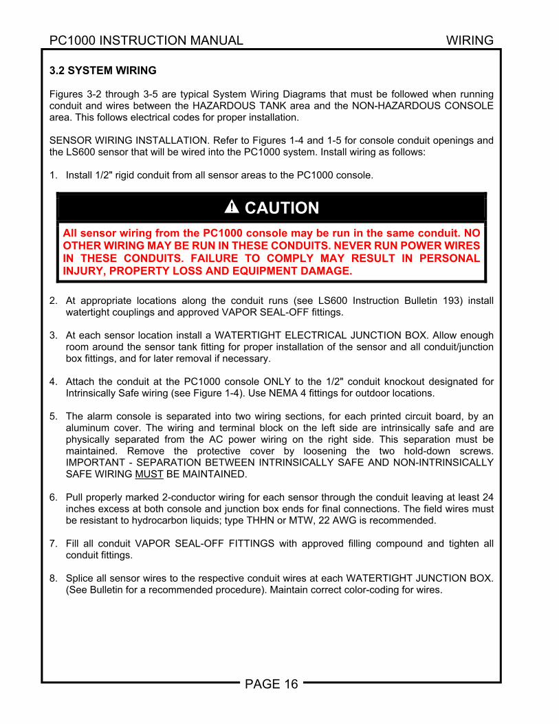
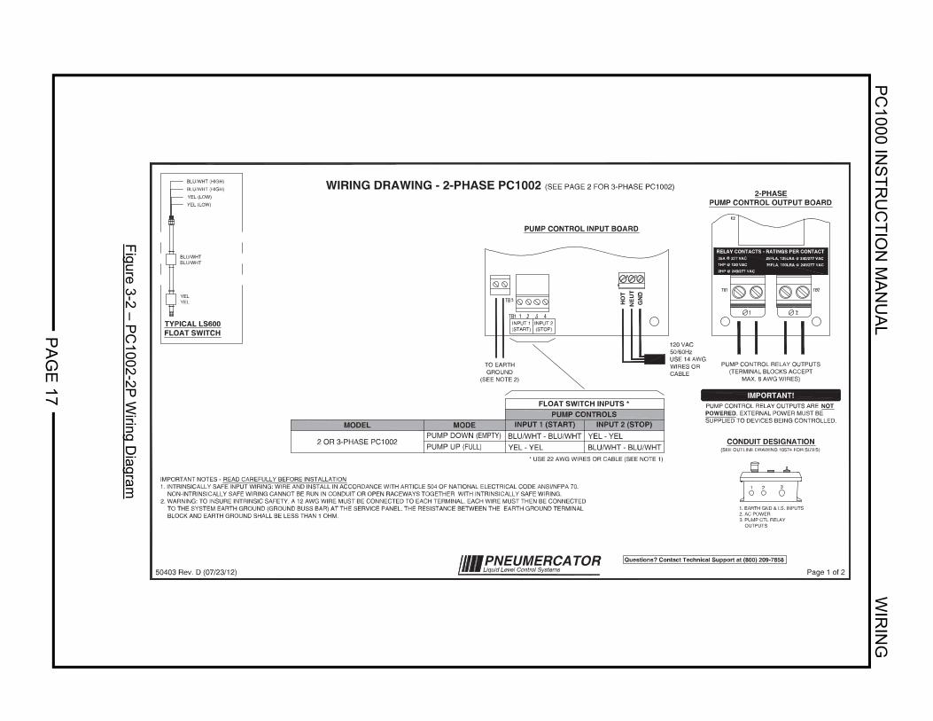
3.2 SYSTEM WIRING Figures 3-2 through 3-5 are typical System Wiring Diagrams that must be followed when running conduit and wires between the HAZARDOUS TANK area and the NON-HAZARDOUS CONSOLE area. This follows electrical codes for proper installation. SENSOR WIRING INSTALLATION. Refer to Figures 1-4 and 1-5 for console conduit openings and the LS600 sensor that will be wired into the PC1000 system. Install wiring as follows: 1. Install 1/2" rigid conduit from all sensor areas to the PC1000 console.
CAUTION
All sensor wiring from the PC1000 console may be run in the same conduit. NO OTHER WIRING MAY BE RUN IN THESE CONDUITS. NEVER RUN POWER WIRES IN THESE CONDUITS. FAILURE TO COMPLY MAY RESULT IN PERSONAL INJURY, PROPERTY LOSS AND EQUIPMENT DAMAGE.
2. At appropriate locations along the conduit runs (see LS600 Instruction Bulletin 193) install
watertight couplings and approved VAPOR SEAL-OFF fittings. 3. At each sensor location install a WATERTIGHT ELECTRICAL JUNCTION BOX. Allow enough
room around the sensor tank fitting for proper installation of the sensor and all conduit/junction box fittings, and for later removal if necessary.
4. Attach the conduit at the PC1000 console ONLY to the 1/2" conduit knockout designated for
Intrinsically Safe wiring (see Figure 1-4). Use NEMA 4 fittings for outdoor locations.
5. The alarm console is separated into two wiring sections, for each printed circuit board, by an aluminum cover. The wiring and terminal block on the left side are intrinsically safe and are physically separated from the AC power wiring on the right side. This separation must be maintained. Remove the protective cover by loosening the two hold-down screws. IMPORTANT - SEPARATION BETWEEN INTRINSICALLY SAFE AND NON-INTRINSICALLY SAFE WIRING MUST BE MAINTAINED.
6. Pull properly marked 2-conductor wiring for each sensor through the conduit leaving at least 24
inches excess at both console and junction box ends for final connections. The field wires must be resistant to hydrocarbon liquids; type THHN or MTW, 22 AWG is recommended.
7. Fill all conduit VAPOR SEAL-OFF FITTINGS with approved filling compound and tighten all
conduit fittings. 8. Splice all sensor wires to the respective conduit wires at each WATERTIGHT JUNCTION BOX.
(See Bulletin for a recommended procedure). Maintain correct color-coding for wires.
PC
1000 INS
TR
UC
TIO
N M
AN
UA
L W
IRIN
G
PA
GE
17
Figure 3-2 – P
C1002-2P
Wiring D
iagram
PUMP CONTROL INPUT BOARD
GN
DN
EU
TH
OT
IMPORTANT NOTES - READ CAREFULLY BEFORE INSTALLATION1. INTRINSICALLY SAFE INPUT WIRING: WIRE AND INSTALL IN ACCORDANCE WITH ARTICLE 504 OF NATIONAL ELECTRICAL CODE ANSI/NFPA 70. NON-INTRINSICALLY SAFE WIRING CANNOT BE RUN IN CONDUIT OR OPEN RACEWAYS TOGETHER WITH INTRINSICALLY SAFE WIRING.2. WARNING: TO INSURE INTRINSIC SAFETY, A 12 AWG WIRE MUST BE CONNECTED TO EACH TERMINAL. EACH WIRE MUST THEN BE CONNECTED TO THE SYSTEM EARTH GROUND (GROUND BUSS BAR) AT THE SERVICE PANEL. THE RESISTANCE BETWEEN THE EARTH GROUND TERMINAL BLOCK AND EARTH GROUND SHALL BE LESS THAN 1 OHM.
WIRING DRAWING - 2-PHASE PC1002 (SEE PAGE 2 FOR 3-PHASE PC1002)
Page 1 of 250403 Rev. D (07/23/12)
TYPICAL LS600FLOAT SWITCH
2 OR 3-PHASE PC1002PUMP DOWN (EMPTY)
EDOMLEDOM INPUT 1 (START) INPUT 2 (STOP)
FLOAT SWITCH INPUTS *PUMP CONTROLS
BLU/WHT - BLU/WHTYEL - YEL
YEL - YELBLU/WHT - BLU/WHT
YEL (LOW)
YEL (LOW)
BLU/WHT (HIGH)
BLU/WHT (HIGH)
BLU/WHTBLU/WHT
YELYEL
120 VAC50/60HzUSE 14 AWGWIRES ORCABLE
* USE 22 AWG WIRES OR CABLE (SEE NOTE 1)
TO EARTHGROUND
(SEE NOTE 2)
2-PHASEPUMP CONTROL OUTPUT BOARD
PUMP CONTROL RELAY OUTPUTS(TERMINAL BLOCKS ACCEPT
MAX. 8 AWG WIRES)
IMPORTANT!PUMP CONTROL RELAY OUTPUTS ARE NOTPOWERED . EXTERNAL POWER MUST BESUPPLIED TO DEVICES BEING CONTROLLED.
CONDUIT DESIGNATION(SEE OUTLINE DRAWING 10574 FOR SIZES)
1. EARTH GND & I.S. INPUTS2. AC POWER3. PUMP CTL RELAY OUTPUTS
1 2 3
PUMP UP (FULL)
RELAY CONTACTS - RATINGS PER CONTACT
2HP @ 240/277 VAC
1HP @ 120 VAC
35A @ 277 VAC 25FLA, 125LRA @ 240/277 VAC
35FLA, 100LRA @ 240/277 VAC
INPUT 1(START)
INPUT 2(STOP)
PNEUMERCATORLiquid Level Control Systems
Questions? Contact Technical Support at (800) 209-7858
PC
1000 INS
TR
UC
TIO
N M
AN
UA
L W
IRIN
G
PA
GE
18
Figure 3-3 – P
C1002-3P
Wiring D
iagram
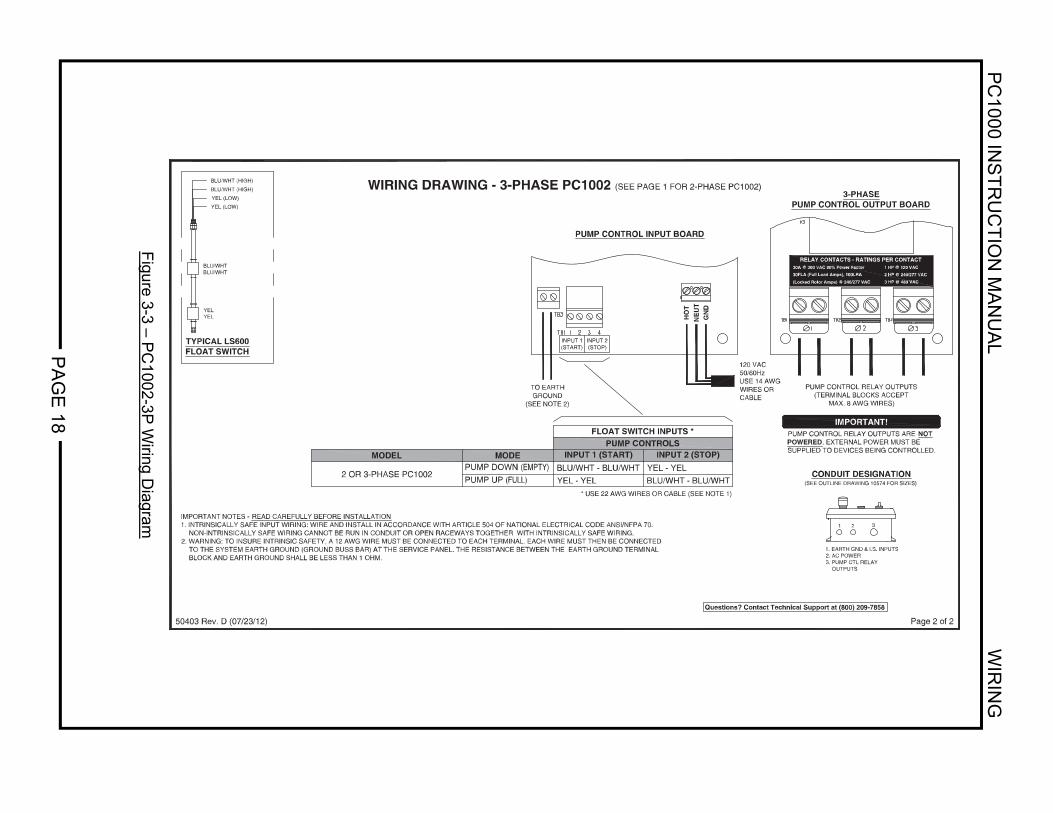
PUMP CONTROL INPUT BOARD
GN
DN
EU
TH
OT
IMPORTANT NOTES - READ CAREFULLY BEFORE INSTALLATION1. INTRINSICALLY SAFE INPUT WIRING: WIRE AND INSTALL IN ACCORDANCE WITH ARTICLE 504 OF NATIONAL ELECTRICAL CODE ANSI/NFPA 70. NON-INTRINSICALLY SAFE WIRING CANNOT BE RUN IN CONDUIT OR OPEN RACEWAYS TOGETHER WITH INTRINSICALLY SAFE WIRING.2. WARNING: TO INSURE INTRINSIC SAFETY, A 12 AWG WIRE MUST BE CONNECTED TO EACH TERMINAL. EACH WIRE MUST THEN BE CONNECTED TO THE SYSTEM EARTH GROUND (GROUND BUSS BAR) AT THE SERVICE PANEL. THE RESISTANCE BETWEEN THE EARTH GROUND TERMINAL BLOCK AND EARTH GROUND SHALL BE LESS THAN 1 OHM.
WIRING DRAWING - 3-PHASE PC1002 (SEE PAGE 1 FOR 2-PHASE PC1002)
Page 2 of 250403 Rev. D (07/23/12)
TYPICAL LS600FLOAT SWITCH
2 OR 3-PHASE PC1002PUMP DOWN (EMPTY)
EDOMLEDOM INPUT 1 (START) INPUT 2 (STOP)
FLOAT SWITCH INPUTS *PUMP CONTROLS
BLU/WHT - BLU/WHTYEL - YEL
YEL - YELBLU/WHT - BLU/WHT
120 VAC50/60HzUSE 14 AWGWIRES ORCABLE
* USE 22 AWG WIRES OR CABLE (SEE NOTE 1)
TO EARTHGROUND
(SEE NOTE 2)
CONDUIT DESIGNATION(SEE OUTLINE DRAWING 10574 FOR SIZES)
1. EARTH GND & I.S. INPUTS2. AC POWER3. PUMP CTL RELAY OUTPUTS
1 2 3
PUMP UP (FULL)
3-PHASEPUMP CONTROL OUTPUT BOARD
PUMP CONTROL RELAY OUTPUTS(TERMINAL BLOCKS ACCEPT
MAX. 8 AWG WIRES)
PUMP CONTROL RELAY OUTPUTS ARE NOTPOWERED . EXTERNAL POWER MUST BESUPPLIED TO DEVICES BEING CONTROLLED.
IMPORTANT!
RELAY CONTACTS - RATINGS PER CONTACT30A @ 300 VAC 80% Power Facto r 1 HP @ 120 VAC
30FLA (Full Load Amps), 100LRA 2 HP @ 240/277 VAC
3 HP @ 480 VAC(Locked Rotor Amps) @ 240/277 VAC
INPUT 1(START)
INPUT 2(STOP)
YEL (LOW)
YEL (LOW)
BLU/WHT (HIGH)
BLU/WHT (HIGH)
BLU/WHTBLU/WHT
YELYEL
Questions? Contact Technical Support at (800) 209-7858
PC
1000 INS
TR
UC
TIO
N M
AN
UA
L W
IRIN
G
PA
GE
19
Figure 3-4 – P
C1003-2P
/ PC
1004-2P W
iring Diagram
TYPICAL LS600FLOAT SWITCH
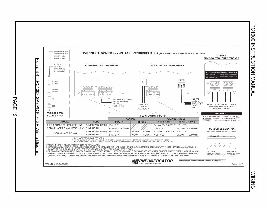
ALARM INPUT/OUTPUT BOARD PUMP CONTROL INPUT BOARD
GN
DN
EU
TH
OT
CONDUIT DESIGNATION(SEE OUTLINE DRAWING 10574 FOR SIZES)
1 2 3 4 5
1. I.S. INPUTS2. RELAY OUTPUTS3. EARTH GND & I.S. INPUTS
4. AC POWER5. PUMP CTL RELAY OUTPUTS
IMPORTANT NOTES - READ CAREFULLY BEFORE INSTALLATION1. INTRINSICALLY SAFE INPUT WIRING: WIRE AND INSTALL IN ACCORDANCE WITH ARTICLE 504 OF NATIONAL ELECTRICAL CODE ANSI/NFPA 70. N ON-INTRINSICALLY SAFE WIRING CANNOT BE RUN IN CONDUIT OR OPEN RACEWAYS TOGETHER WITH INTRINSICALLY SAFE WIRING.2. DRY CONTACT SWITCH OUTPUT: WIRE TO COMMON AND EITHER NORMALLY OPEN OR NORMALLY CLOSED FOR DESIRED SWITCH CONTACT. OUTPUT RAT ED 3 AMPS AT 120 VAC.3. WARNING: TO INSURE INTRINSIC SAFETY, A 12 AWG WIRE MUST BE CONNECTED TO EACH TERMINAL. EACH WIRE MUST THEN BE CONNECTED TO T HE SYSTEM EARTH GROUND (GROUND BUSS BAR) AT THE SERVICE PANEL. THE RESISTANCE BETWEEN THE EARTH GROUND TERMINAL BLOCK AND EARTH GROUND SHALL BE LESS THAN 1 OHM.
WIRING DRAWING - 2-PHASE PC1003/PC1004 (SEE PAGE 2 FOR 3-PHASE PC1003/PC1004)
Page 1 of 250399 Rev. E (04/27/16)
VIO/WHT - VIO/WHTVIO/WHT - VIO/WHT
BRN - BRNBRN - BRN
PUMP DOWN(EMPTY)EDOMLEDOM
BRN - BRNVIO/WHT - VIO/WHT
INPUT 1 (START) INPUT 2 (STOP)PUMP CONTROLSALARMS
INPUT 1 INPUT 2
FLOAT SWITCH INPUTSa
BLU/WHTBLU/WHT
YELYEL
BLU/WHT (HIGH)
BLU/WHT (HIGH)
YEL (LOW)
YEL (LOW)
BRNBRN
BRN (LOW LOW)
BRN (LOW LOW)
VIO/WHT (HIGH HIGH)
VIO/WHT (HIGH HIGH)
VIO/WHTVIO/WHT
BLU/WHT - BLU/WHTYEL - YEL
YEL - YELBLU/WHT - BLU/WHT
a USE 22 AWG WIRES OR CABLE (SEE NOTE 1)b FOR PC1003L "PUMP UP" APPLICATIONS, "YEL - YEL" MUST BE CONNECTED TO INPUT 1 (START) AND "BLU/WHT - BLU/WHT" TO INPUT 2 (STOP).c FOR PC1003H "PUMP DOWN" APPLICATIONS, "BLU/WHT - BLU/WHT" MUST BE CONNECTED TO INPUT 1 (START) AND "YEL - YEL" TO INPUT 2 (STOP).
PUMP CONTROL RELAY OUTPUTS(TERMINAL BLOCKS ACCEPT
MAX. 8 AWG WIRES)
120 VAC50/60HzUSE 14 AWGWIRES ORCABLE
TO EARTHGROUND
(SEE NOTE 3)
RELAY OUTPUT WIRINGUSE 22 AWG WIRESOR CABLE(SEE NOTE 2)
BLU/WHT - BLU/WHTYEL - YEL
YEL - YELBLU/WHT - BLU/WHT
PUMP CONTROL RELAY OUTPUTS ARE NOTPOWERED. EXTERNAL POWER MUST BESUPPLIED TO DEVICES BEING CONTROLLED.
IMPORTANT!
2-PHASEPUMP CONTROL OUTPUT BOARD
2 OR 3-PHASE PC1004
PUMP UP (FULL)PUMP DOWN(EMPTY)
PUMP UP (FULL)
RELAY CONTACTS - RATINGS PER CONTACT
2HP @ 240/277 VAC1HP @ 120 VAC35A @ 277 VAC 25FLA, 125LRA @ 240/277 VAC
35FLA, 100LRA @ 240/277 VAC
INPUT 1(START)
INPUT 2(STOP)
PNEUMERCATORLiquid Level Control Systems
Questions? Contact Technical Support at (800) 209-7858
2 OR 3-PHASE PC1003L(CRIT. LOW)b
2 OR 3-PHASE PC1003H(CRIT. HIGH)c
PC
1000 INS
TR
UC
TIO
N M
AN
UA
L W
IRIN
G
PA
GE
20
Figure 3-5 – P
C1003-3P
/ PC
1004-3P W
iring Diagram
TYPICAL LS600FLOAT SWITCH
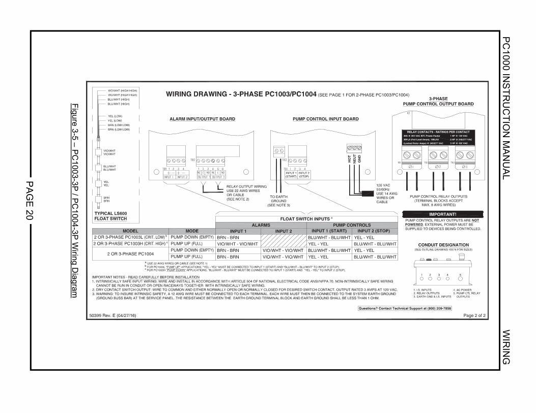
ALARM INPUT/OUTPUT BOARD PUMP CONTROL INPUT BOARD
GN
DN
EU
TH
OT
CONDUIT DESIGNATION(SEE OUTLINE DRAWING 10574 FOR SIZES)
1 2 3 4 5
1. I.S. INPUTS2. RELAY OUTPUTS3. EARTH GND & I.S. INPUTS
4. AC POWER5. PUMP CTL RELAY OUTPUTS
WIRING DRAWING - 3-PHASE PC1003/PC1004 (SEE PAGE 1 FOR 2-PHASE PC1003/PC1004)
Page 2 of 250399 Rev. E (04/27/16)
120 VAC50/60HzUSE 14 AWGWIRES ORCABLE
TO EARTHGROUND
(SEE NOTE 3)
RELAY OUTPUT WIRINGUSE 22 AWG WIRESOR CABLE(SEE NOTE 2)
3-PHASEPUMP CONTROL OUTPUT BOARD
PUMP CONTROL RELAY OUTPUTS(TERMINAL BLOCKS ACCEPT
MAX. 8 AWG WIRES)
PUMP CONTROL RELAY OUTPUTS ARE NOTPOWERED. EXTERNAL POWER MUST BESUPPLIED TO DEVICES BEING CONTROLLED.
IMPORTANT!
RELAY CONTACTS - RATINGS PER CONTACT30A @ 300 VAC 80% Power Factor 1 HP @ 120 VAC30FLA (Full Load Amps), 100LRA 2 HP @ 240/277 VAC
3 HP @ 480 VAC(Locked Rotor Amps) @ 240/277 VAC
INPUT 1(START)
INPUT 2(STOP)
BLU/WHTBLU/WHT
YELYEL
BRNBRN
VIO/WHTVIO/WHT
BLU/WHT (HIGH)
BLU/WHT (HIGH)
YEL (LOW)
YEL (LOW)
BRN (LOW LOW)
BRN (LOW LOW)
VIO/WHT (HIGH HIGH)
VIO/WHT (HIGH HIGH)
Questions? Contact Technical Support at (800) 209-7858
IMPORTANT NOTES - READ CAREFULLY BEFORE INSTALLATION1. INTRINSICALLY SAFE INPUT WIRING: WIRE AND INSTALL IN ACCORDANCE WITH ARTICLE 504 OF NATIONAL ELECTRICAL CODE ANSI/NFPA 70. N ON-INTRINSICALLY SAFE WIRING CANNOT BE RUN IN CONDUIT OR OPEN RACEWAYS TOGETHER WITH INTRINSICALLY SAFE WIRING.2. DRY CONTACT SWITCH OUTPUT: WIRE TO COMMON AND EITHER NORMALLY OPEN OR NORMALLY CLOSED FOR DESIRED SWITCH CONTACT. OUTPUT RAT ED 3 AMPS AT 120 VAC.3. WARNING: TO INSURE INTRINSIC SAFETY, A 12 AWG WIRE MUST BE CONNECTED TO EACH TERMINAL. EACH WIRE MUST THEN BE CONNECTED TO T HE SYSTEM EARTH GROUND (GROUND BUSS BAR) AT THE SERVICE PANEL. THE RESISTANCE BETWEEN THE EARTH GROUND TERMINAL BLOCK AND EARTH GROUND SHALL BE LESS THAN 1 OHM.
VIO/WHT - VIO/WHTVIO/WHT - VIO/WHT
BRN - BRNBRN - BRN
PUMP DOWN(EMPTY)EDOMLEDOM
BRN - BRNVIO/WHT - VIO/WHT
INPUT 1 (START) INPUT 2 (STOP)PUMP CONTROLSALARMS
INPUT 1 INPUT 2
FLOAT SWITCH INPUTSa
BLU/WHT - BLU/WHTYEL - YEL
YEL - YELBLU/WHT - BLU/WHT
a USE 22 AWG WIRES OR CABLE (SEE NOTE 1)b FOR PC1003L "PUMP UP" APPLICATIONS, "YEL - YEL" MUST BE CONNECTED TO INPUT 1 (START) AND "BLU/WHT - BLU/WHT" TO INPUT 2 (STOP).c FOR PC1003H "PUMP DOWN" APPLICATIONS, "BLU/WHT - BLU/WHT" MUST BE CONNECTED TO INPUT 1 (START) AND "YEL - YEL" TO INPUT 2 (STOP).
BLU/WHT - BLU/WHTYEL - YEL
YEL - YELBLU/WHT - BLU/WHT
2 OR 3-PHASE PC1004
PUMP UP (FULL)PUMP DOWN(EMPTY)
PUMP UP (FULL)
2 OR 3-PHASE PC1003L(CRIT. LOW)b
2 OR 3-PHASE PC1003H(CRIT. HIGH)c
PC1000 INSTRUCTION MANUAL WIRING
PAGE 21
9. Connect sensor wires to the PC1000 INPUT TERMINALS following the matching diagram in
Figures 3-2 through 3-5. The terminal blocks may be removed for ease of wiring by pressing down toward the conduit openings. Note that for PC1003/4 consoles, power need only be wired to the Pump Control Input Board. Maintain correct polarity between wires and respective terminal points.
10. Properly dress all wires inside the wiring sections and re-install the protective aluminum cover
over the terminals. 11. Sensors should be logically identified as to location and type and recorded on the Sensor map
provided in this manual, SECTION 3.3.
CAUTION
Sensor wires are to be connected ONLY to the designated input terminals of the INTRINSIC SAFETY compartment. DO NOT allow sensor wires to cross over into the non-intrinsically safe section. FAILURE TO COMPLY MAY RESULT IN PERSONAL INJURY, PROPERTY LOSS AND EQUIPMENT DAMAGE.
CAUTION
Relay output terminals are located on the NON-INTRINSICALLY SAFE side of the console. ALL wiring to these terminals MUST enter through the designated conduit opening. Refer to FIGURE 1-4. FAILURE TO COMPLY MAY RESULT IN PERSONAL INJURY, PROPERTY LOSS AND EQUIPMENT DAMAGE.
PC1000 INSTRUCTION MANUAL WIRING
PAGE 22
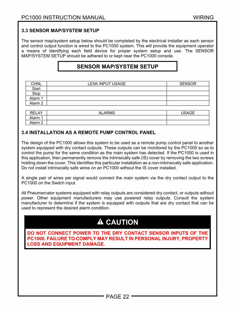
3.3 SENSOR MAP/SYSTEM SETUP The sensor map/system setup below should be completed by the electrical installer as each sensor and control output function is wired to the PC1000 system. This will provide the equipment operator a means of identifying each field device for proper system setup and use. The SENSOR MAP/SYSTEM SETUP should be adhered to or kept near the PC1000 console.
CHNL LEAK INPUT USAGE SENSORStart Stop
Alarm 1 Alarm 2
RELAY ALARMS USAGEAlarm 1 Alarm 2
3.4 INSTALLATION AS A REMOTE PUMP CONTROL PANEL The design of the PC1000 allows this system to be used as a remote pump control panel to another system equipped with dry contact outputs. These outputs can be monitored by the PC1000 so as to control the pump for the same condition as the main system has detected. If the PC1000 is used in this application, then permanently remove the intrinsically safe (IS) cover by removing the two screws holding down the cover. This identifies this particular installation as a non-intrinsically safe application. Do not install intrinsically safe wires on an PC1000 without the IS cover installed. A single pair of wires per signal would connect the main system via the dry contact output to the PC1000 on the Switch input. All Pneumercator systems equipped with relay outputs are considered dry contact, or outputs without power. Other equipment manufacturers may use powered relay outputs. Consult the system manufacturer to determine if the system is equipped with outputs that are dry contact that can be used to represent the desired alarm condition.
CAUTION
DO NOT CONNECT POWER TO THE DRY CONTACT SENSOR INPUTS OF THE PC1000. FAILURE TO COMPLY MAY RESULT IN PERSONAL INJURY, PROPERTY LOSS AND EQUIPMENT DAMAGE.
SENSOR MAP/SYSTEM SETUP
PC1000 INSTRUCTION MANUAL OPERATION
PAGE 23
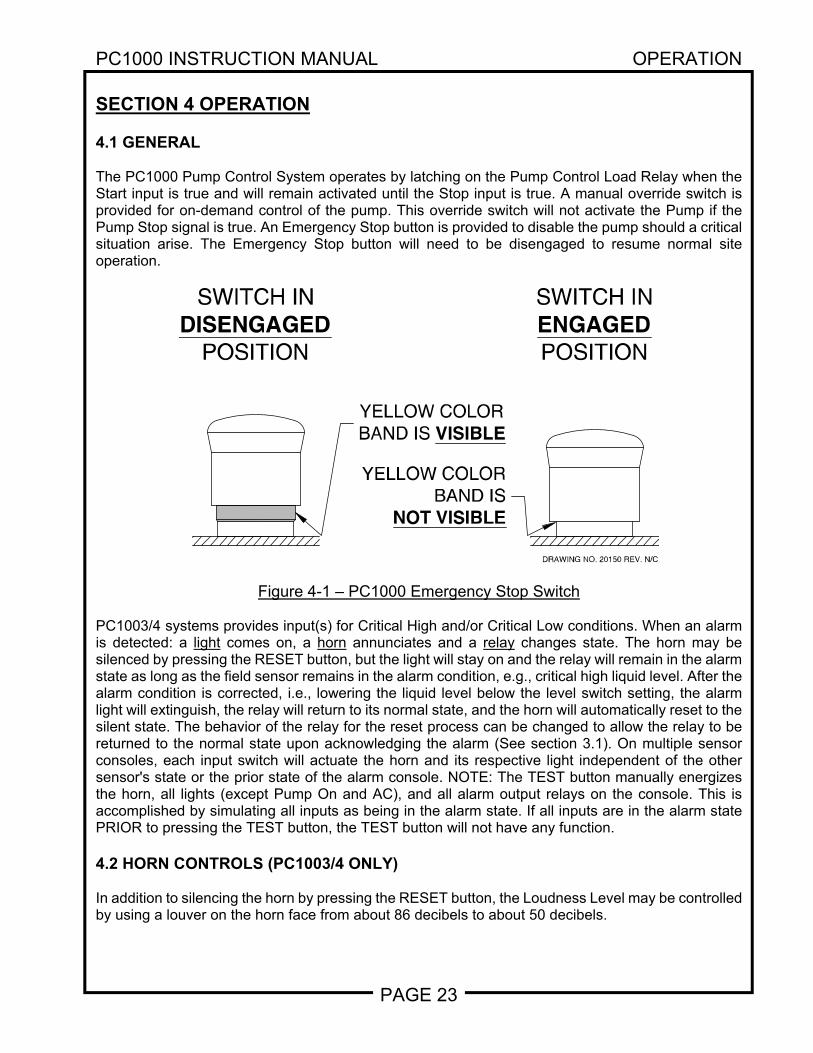
SECTION 4 OPERATION 4.1 GENERAL The PC1000 Pump Control System operates by latching on the Pump Control Load Relay when the Start input is true and will remain activated until the Stop input is true. A manual override switch is provided for on-demand control of the pump. This override switch will not activate the Pump if the Pump Stop signal is true. An Emergency Stop button is provided to disable the pump should a critical situation arise. The Emergency Stop button will need to be disengaged to resume normal site operation.
Figure 4-1 – PC1000 Emergency Stop Switch
PC1003/4 systems provides input(s) for Critical High and/or Critical Low conditions. When an alarm is detected: a light comes on, a horn annunciates and a relay changes state. The horn may be silenced by pressing the RESET button, but the light will stay on and the relay will remain in the alarm state as long as the field sensor remains in the alarm condition, e.g., critical high liquid level. After the alarm condition is corrected, i.e., lowering the liquid level below the level switch setting, the alarm light will extinguish, the relay will return to its normal state, and the horn will automatically reset to the silent state. The behavior of the relay for the reset process can be changed to allow the relay to be returned to the normal state upon acknowledging the alarm (See section 3.1). On multiple sensor consoles, each input switch will actuate the horn and its respective light independent of the other sensor's state or the prior state of the alarm console. NOTE: The TEST button manually energizes the horn, all lights (except Pump On and AC), and all alarm output relays on the console. This is accomplished by simulating all inputs as being in the alarm state. If all inputs are in the alarm state PRIOR to pressing the TEST button, the TEST button will not have any function. 4.2 HORN CONTROLS (PC1003/4 ONLY) In addition to silencing the horn by pressing the RESET button, the Loudness Level may be controlled by using a louver on the horn face from about 86 decibels to about 50 decibels.
DRAWING NO. 20150 REV. N/C
SWITCH INDISENGAGED
POSITION
SWITCH INENGAGEDPOSITION
YELLOW COLORBAND IS
NOT VISIBLE
YELLOW COLORBAND IS VISIBLE
PC1000 INSTRUCTION MANUAL TROUBLESHOOTING
PAGE 24
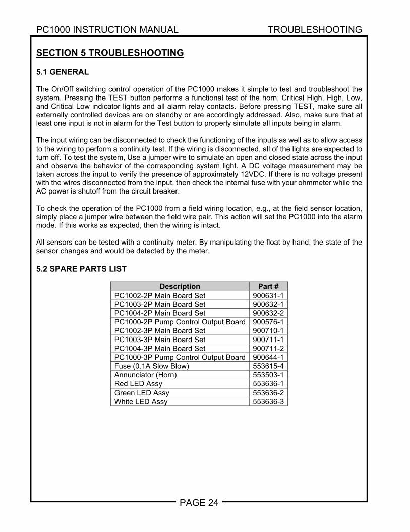
SECTION 5 TROUBLESHOOTING 5.1 GENERAL The On/Off switching control operation of the PC1000 makes it simple to test and troubleshoot the system. Pressing the TEST button performs a functional test of the horn, Critical High, High, Low, and Critical Low indicator lights and all alarm relay contacts. Before pressing TEST, make sure all externally controlled devices are on standby or are accordingly addressed. Also, make sure that at least one input is not in alarm for the Test button to properly simulate all inputs being in alarm. The input wiring can be disconnected to check the functioning of the inputs as well as to allow access to the wiring to perform a continuity test. If the wiring is disconnected, all of the lights are expected to turn off. To test the system, Use a jumper wire to simulate an open and closed state across the input and observe the behavior of the corresponding system light. A DC voltage measurement may be taken across the input to verify the presence of approximately 12VDC. If there is no voltage present with the wires disconnected from the input, then check the internal fuse with your ohmmeter while the AC power is shutoff from the circuit breaker. To check the operation of the PC1000 from a field wiring location, e.g., at the field sensor location, simply place a jumper wire between the field wire pair. This action will set the PC1000 into the alarm mode. If this works as expected, then the wiring is intact. All sensors can be tested with a continuity meter. By manipulating the float by hand, the state of the sensor changes and would be detected by the meter. 5.2 SPARE PARTS LIST
Description Part # PC1002-2P Main Board Set 900631-1PC1003-2P Main Board Set 900632-1PC1004-2P Main Board Set 900632-2PC1000-2P Pump Control Output Board 900576-1PC1002-3P Main Board Set 900710-1PC1003-3P Main Board Set 900711-1PC1004-3P Main Board Set 900711-2PC1000-3P Pump Control Output Board 900644-1Fuse (0.1A Slow Blow) 553615-4Annunciator (Horn) 553503-1Red LED Assy 553636-1Green LED Assy 553636-2White LED Assy 553636-3
PC1000 INSTRUCTION MANUAL MAINTENANCE
PAGE 25
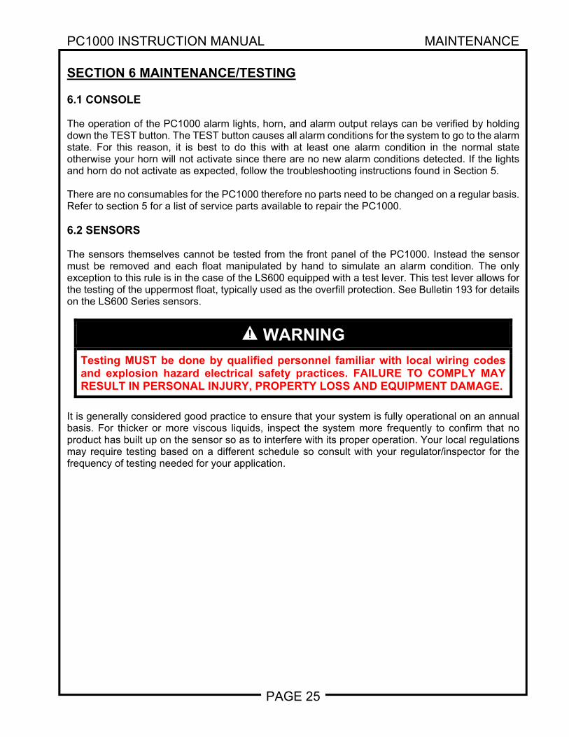
SECTION 6 MAINTENANCE/TESTING 6.1 CONSOLE The operation of the PC1000 alarm lights, horn, and alarm output relays can be verified by holding down the TEST button. The TEST button causes all alarm conditions for the system to go to the alarm state. For this reason, it is best to do this with at least one alarm condition in the normal state otherwise your horn will not activate since there are no new alarm conditions detected. If the lights and horn do not activate as expected, follow the troubleshooting instructions found in Section 5. There are no consumables for the PC1000 therefore no parts need to be changed on a regular basis. Refer to section 5 for a list of service parts available to repair the PC1000. 6.2 SENSORS The sensors themselves cannot be tested from the front panel of the PC1000. Instead the sensor must be removed and each float manipulated by hand to simulate an alarm condition. The only exception to this rule is in the case of the LS600 equipped with a test lever. This test lever allows for the testing of the uppermost float, typically used as the overfill protection. See Bulletin 193 for details on the LS600 Series sensors.
WARNING
Testing MUST be done by qualified personnel familiar with local wiring codes and explosion hazard electrical safety practices. FAILURE TO COMPLY MAY RESULT IN PERSONAL INJURY, PROPERTY LOSS AND EQUIPMENT DAMAGE.
It is generally considered good practice to ensure that your system is fully operational on an annual basis. For thicker or more viscous liquids, inspect the system more frequently to confirm that no product has built up on the sensor so as to interfere with its proper operation. Your local regulations may require testing based on a different schedule so consult with your regulator/inspector for the frequency of testing needed for your application.


WARRANTY
We warrant that our tank gauges, if installed according to instructions will be free from defects in material and workmanship for a period of one (1) year following the date of original shipment by us. Our liability under this warranty shall be limited to, at our option, (i) repair of the defective tank gauge, (ii) replacement of the original tank gauge with new, or (iii) refund of the original purchase price; and, we shall not be liable for any labor, other installation costs, indirect or consequential damages, or other damages in connection with such gauge. This constitutes our obligation and none other stated for any purpose except the above shall apply. Contact Pneumercator for detailed warranty documentation.
REVISION 101008
Pneumercator Co. 1785 Expressway Drive North
Hauppauge, NY 11788 TEL:(631) 293-8450 FAX:(631) 293-8533
www.pneumercator.com
Distributed by: PNEUMERCATORLiquid Level Control Systems