Embed Size (px)
Citation preview

SHEET SLITTERS
METAL PROCESSING EQUIPMENT
PATENT No. 3195388
MODEL 3350, 3351 and 3353
INSTRUCTION MANUAL
GARY MACHINERYGARY MACHINERY LLCLLC
1931 East Main StreetGriffith, IN 46319
Phone: 219/ 980-5700FAX: 219/ 980-0405

OPERATOR SAFETY GUIDELINES
1. All operators and maintenance people must familiarize themselves with the location of the power shut-off.
2. Be sure you know the machine – capacity, controls, operating mode and safeguarding.
3. Never place any part of your body at the point of operation when the machine is running.
4. Never operate, service repair or adjust the machine without proper instruction from your supervisor and without reading and understanding the operators manual.
5. Never operate the machine without guards or barriers. 6. If the machine requires cleaning, service, adjustment, or should become jammed,
do not insert hand in point of operation to remove assist, release, service or adjust unless the following is done.
� Shut off machine � Pull plug – remove power source � Make sure supervisor is present
7. Make certain all personnel are away from the equipment before operating. 8. Keep alert – keep your mind on your job. 9. When leaving your machine, turn the power OFF – controls inoperative.
10. Keep your work area clean. 11. Wear snug fitting clothes.
FAILURE TO FOLLOW SAFE OPERATING PROCEDURES MAY RESULT IN SERIOUS INJURY – TO YOU OR ANOTHER EMPLOYEE
1. Removal of guards punishable by law. 2. Become familiar with power shut-offs before operating this machine. 3. If machine requires service, adjustment or should become jammed, do not insert hand in point of operation to remove, assist, release, service, or adjust, unless the following is done:
o Shut off machine; o Pull plug - remove power source; o Make sure supervisor is present;
4. Any malfunctions of this machine should be brought to the attention of foreman or supervisor. 5. Instructions should be available for operation and he should be reviewed on this information before being permitted to operate this machine. 6. It is suggested that after the equipment has been installed barrier guards be erected where needed to prevent personnel entry into potential hazard areas.

Gary Machinery LLC “Sheet Slitter” Operating & Instruction Manual
Introduction: The Gary Machinery Sheet Slitter is thoroughly inspected before leaving our plant. This includes running material through the unit to be sure that all components are operating properly and that a satisfactory cut can be made. To simplify the machine set up and to maintain proper operating, the following recommended set up steps have been outlined. Please read these carefully, and if any questions arise, call us at any time. Opening the Crate: The Slitters are shipped crated on skids. Once the crate is removed, the unit should be checked for damages that may have occurred during transit. The slitter can be left on the skid or it can be removed and permanently located. Once positioned and ready to operate, remove the rust protective spray that was applied at the factory. You are now ready to plug the machine in. Models 3350 & 3351: These machines are 110 Volts as a standard and will have a standard plug. If you ordered a 220-volt machine, you will need to supply the proper plug for your receptacle. Model 3353: This is a 3-phase machine with a voltage of either 220v or 440v. You should verify that the motor has been properly wired for your voltage, and the motor starter has the proper heater size.
SLITTER MOTOR 1 HP 2.1 AMPS @ 460VAC 4.2 AMPS @ 230VAC

Machine Capacity: Going over the rated machine capacity can cause the machine to not cut the material. This is cause by deflection of the arbors. Below is a chart of the rated machine capacities. Note that if you are using Stripper Rings, that you will have reduced capacity.
Knife Set-up: You will need to set the knives for the size cuts required. The knives are equipped with a setscrew and gib key arrangement that locks it to the shaft. To make an adjustment use the “T” Handled Allen Wrench to loosen these setscrews and slide the knives in the position required. This position is determined by measuring from the sheet gauge to the cutting edge of the knife. Once the placement of the knife has been determined, secure the setscrews by alternately snugging (NOT TIGHTENING) up each setscrew. Move the mating knife to this knife and set the proper clearance between the knives using a feeler gauge. Set the remaining knives up is this same manner. Once this is done, jog the machine at least one revolution, then tightening them up a second time to help prevent “twisting” the knife. Use this chart to set the proper horizontal clearance:
MODEL Thickness
Ga. In. Mm.
3351 Thrifty
3350 Super Duty
3353 (3 Phase)
Super Duty
30 .015” .30 6 12 12
28 .018” .37 4 8 8
26 .021” .45 3 6 6
24 .027” .60 3 4 4
22 .033” .75 2 4 4
20 .039” .91 2 3 3
18 .051” 1.2 1 2 2
16 .063” 1.5 1 1 1
HORIZONTAL CLEARANCE
8% of stock thickness.020” and over
.00075” to .001”.010” - .018”
.0005” to .00075”.006” - .010”
.006 AND UNDER NO CLEARANCE
STOCK THICKNES CLEARANCE
To obtain satisfactory results with any slitting machine it is vital that the horizontal clearances be properly set. Final clearance adjustments are best determined by making test runs with the actual material to be slit. However these setting have proven to be fairly accurate. Allowance should be made for deflection of the arbors, which occurs due to the thickness and type of material being cut. Note: Softer materials may need less side clearance and harder materials may need more side clearance.
Stripper Rings for the Superduty Slitters are beneficial for light gauge prepainted
material. (This will reduce the cut capacity.)

Note proper tooling arrangement (View is exaggerated to show clarity)
Use of the Sheet Guide: The sheet guide supplied with each slitter is used to hold material to the gauge. As material is fed into the unit, locate the sheet guide on the non-gauge side of the sheet. Only exert sufficient pressure to keep the material to the gauge. This will insure dimensional control and safe operation. For Model 3350 machine equipped with stripper rings: To position the stripper rings, loosen the quip-clamp and then slide them either directly over a bottom knife or under an upper knife. Be careful not to over-tighten the clamps as this will increase the size of the rings and can prevent the slitter from cutting the material. They only need to be tight enough to hold the ring in position. The rings can also be placed over the top of each other to help pull the material straight through when you are making an out-of-balanced cut. For Model 3350 machine equipped with stripper fingers: To position these fingers, loosen the setscrew and then slide them either directly over a bottom knife or under an upper knife. The second setscrew provided sets clearance between knife and finger. Normal clearance would allow a slip fit for whatever gauge material is being cut. Caution should be taken not to get the fingers to tight. If this happens it can cause the sheet to pull away from the gauge.
Standard Tooling ArrangementWithout Material Strippers
(Model #3351)
Stripper Ring Tooling Arrangement(Models #3350 & 3353)

Lubricating Instructions
To maintain the Gary Machinery Sheet Slitter in its best operating condition and to avoid downtime, the following lubrication points should be checked on a regular schedule. 1. The gear reducer should be checked when received to be sure the oil is at the proper level.
It should then be checked at regular intervals, with visual inspection of oil seals for possible leaks. If oil is required, Browning GL32HT (or equivalent) is recommended. The oil can be added through the plug at the top of the reducer. Caution must be taken not to overfill the unit.
2. The arbors should be wiped down and lubricated with a light oil such as WD-40. This will
help prevent rust and remove debris from the arbor face, which could get under the knives and make them hard to move & adjust. They should be re-lubricated on a daily basis. This re-lube period should be more often if the slitter is operated in extremely dusty atmospheres.
3. The guard on the gauge side of the slitter incorporates the main arbor bearings and provides
access to the chain and gears. Use a heavy-duty chain lube to lubricate chain and gears before replacing the guard. Aerosol form is most convenient and effective.
Operating Hints and Cautions Introduction: To utilize the sheet slitter to its maximum capacity requires familiarization with the machine. The operator of the slitter will gain most of this during actual machine running. The following list contains some of the techniques we have found to maintain a maximum output with a minimum set up time. It also includes an outline of the way to set the unit up for the best slitting results. Finally, at the end of this list, a trouble-shooting guide has been provided covering the most common problems and their solutions.
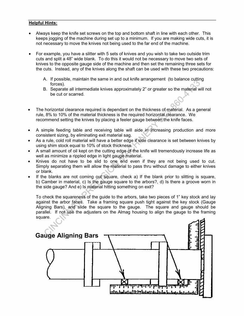
Gauge Aligning Bars
Helpful Hints: • Always keep the knife set screws on the top and bottom shaft in line with each other. This
keeps jogging of the machine during set up to a minimum. If you are making wide cuts, it is not necessary to move the knives not being used to the far end of the machine.
• For example, you have a slitter with 5 sets of knives and you wish to take two outside trim
cuts and split a 48” wide blank. To do this it would not be necessary to move two sets of knives to the opposite gauge side of the machine and then set the remaining three sets for the cuts. Instead, any of the knives along the shaft can be used with these two precautions:
A. If possible, maintain the same in and out knife arrangement (to balance cutting forces).
B. Separate all intermediate knives approximately 2” or greater so the material will not be cut or scarred.
• The horizontal clearance required is dependant on the thickness of material. As a general
rule, 8% to 10% of the material thickness is the required horizontal clearance. We recommend setting the knives by placing a feeler gauge between the knife faces.
• A simple feeding table and receiving table will aide in increasing production and more
consistent sizing, by eliminating exit material sag. • As a rule, cold roll material will have a better edge if side clearance is set between knives by
using shim stock equal to 10% of stock thickness. • A small amount of oil kept on the cutting edge of the knife will tremendously increase life as
well as minimize a rippled edge in light gauge material. • Knives do not have to be slid to one end even if they are not being used to cut.
Simply separating them will allow the material to pass thru without damage to either knives or blank.
• If the blanks are not coming out square, check a) If the blank prior to slitting is square, b) Camber in material, c) Is the gauge square to the arbors?, d) Is there a groove worn in the side gauge? And e) Is material hitting something on exit? To check the squareness of the guide to the arbors, take two pieces of 1” key stock and lay against the arbor faces. Take a framing square push tight against the key stock (Gauge Aligning Bars), and slide the square to the gauge. The square and gauge should be parallel. If not use the adjusters on the Almag housing to align the gauge to the framing square.

• If the cut has an excessive burr, make sure that the side clearance between knives is not excessive. If the cut consistently has a burr, even with correct side clearance the knives probably need sharpening. Note: due to the fixed penetration of this machine the side edge will have a slight roll as a normal condition.
Slitting Trouble Shooting Guide: Burred EdgeBurred EdgeBurred EdgeBurred Edge
• Improper knife separation • Chipped knife • Dull knife • Soft material • Buildup on knife edge
Rolled EdgeRolled EdgeRolled EdgeRolled Edge
• Dull knives • Incorrect stripper arrangement
Material is pulling to the gauge side on exitMaterial is pulling to the gauge side on exitMaterial is pulling to the gauge side on exitMaterial is pulling to the gauge side on exit
• Knife configuration is not balanced • Gauge is out of square • Build up on gauge
Material is pulling to the opposite gauge side on exitMaterial is pulling to the opposite gauge side on exitMaterial is pulling to the opposite gauge side on exitMaterial is pulling to the opposite gauge side on exit
• Knife cut is off balance • Gauge is out of square • Convex camber in sheet
Gauge edge or trim cut is being folded up or downGauge edge or trim cut is being folded up or downGauge edge or trim cut is being folded up or downGauge edge or trim cut is being folded up or down
• Side gauge is out of square with the portion beyond the knives adjusted in too far • Build up on the gauge
Material is not cut through the entire lengthMaterial is not cut through the entire lengthMaterial is not cut through the entire lengthMaterial is not cut through the entire length
• Material run-out table is too low • Stripper ring clamps may have been over-tightened • Knives horizontal gap is too great • Knives are extremely dull • Unit capacity may be exceeded • An arbor may be loose at bearing

A
A
90°
Slitter Knife Sharpening Procedure:
1. The knife sharpening must be done by grinding the side faces. DO NOT GRIND OUTSIDE DIAMETER.
2. Squareness of bore to side face must be maintained (90°)
Instructions for the Removing or the Addition of Knives to Model No. 3350, 3351, 3353
Gary Gang Slitter Units
STEP #1 - Remove chain guard part #9 from unit. Remove chain part #15. (You may need to remove the two bolts at either end of the lower torsion tube, then loosen the main drawbolt nuts to allow the motor base to pivot up to gain slack in the chain.) The chain is linked together with a connecting link also identified as a spring clip. This spring clip can be removed with a screwdriver or other sharp edged device.
STEP #2 - Remove cam locking collars from the non-motor side of the unit. A 3/16" allen
wrench is required for the cam locking collars. After loosening allen screw in cam locking collar, release collar by turning counter-clockwise. If collar does not move to release position then clockwise. (File off burr left by setscrew before removing sprocket.) A 5/32" allen wrench is required for the sprockets. Remove flange bolts from the bearing flanges on the motor side of the unit only.
STEP #3 - Suspend each shaft by using a hoist or similar suspension device. Use rope or nylon
slings to prevent scoring the shafts. Set all knives at least six (6) inches apart, and none nearer than six (6) inches from the motor side of the unit. This refers to upper and lower knives part #10.
STEP #4 - Pry bearing flange off of rolls pins on part #11 from the motor side of the unit.
Identify location of the bearing flanges to insure re-installation in same position on unit.
STEP #5 - Slide the shafts out of the right side bearings located in bearing plate part #2. A
distance of two (2) or three (3) inches is sufficient to permit installation or removal of the knives as is required.
STEP #6 - Re-assemble unit by reversing above procedures.

Part No. Key No. Description Part No. Key No. Description 100014 1 Al-mag End Housing 100011 22 Sheetmetal Sheet Guide 100014 2 Al-mag End Housing 100020 23 Front Leg 100021 3 Knife Arbor- 3"OD x 57" 100019 24 Rear Leg 100016 4 Torsion Tube 285085 25 1-1/4" Drive Nut 100022 5 Cold Roll Gauge 100015 26 Draw Bolt 5/8"-11NC x 6' 100025 6 Table Assembly 275015 27 5/16" 18-N.C. Pull bolts 100024 7 Table Support 100421 28 Gauge Adjusting Bolt x 1.5" 101593 8 3350 & 3353 Motorbase 285018 30 3/8-24 x 1/2" Half Dog Point Set Screw 101596 9 3350 & 3353 Chain Guard 100033 33 Finger Guard 200027 10 3" x 5" x 3/4" STD Alloy Knifes 100031 34 Front Stripper Bar 200028 10a 3" x 5" x 3/4" D2 (HCHC) Knifes - Optional 100032 35 Rear Stripper Bar 285022 12 234 Gib Key 185015 38 Upper Stripper Finger Assembly 200017 13 4020 x 1- 7/16" Arbor Sprocket 185016 39 Lower Stripper Finger Assembly 200018 14a 4020 x 1" Motor Sprocket -STD.(60 fpm) 203100 44 3350/3351 C-H Starter 200005 14b 4015 x 1" Motor Sprocket (40 fpm) 203101 44a 8 Amp Heater (220 Volts) 200016 17a Bearing Flange 203102 44b 14 Amp Heater (110 Volts) 200015 17b 1- 7/16" Arbor Bearing 100029 N.S. Rear Stripper Bar Spacer 200003 18 1/2" ID Chain Idler Bearing 100030 N.S. Front Stripper Bar Spacer 285026 19 Idler Bearing Bolt 200008 N.S. Electric Cord w/Plug 285048 20 No. 40 Chain 200011 N.S. 3/16" T-Handle Allen Wrench 201255 21 3/4HP Rt-angle Gearmotor 45-rpm

N.S. – Not Shown
Part No. Key No. Description Part No. Key No. Description 100014 1 Al-mag End Housing 200003 15 1/2" ID Chain Idler Bearing 100014 2 Al-mag End Housing 285026 16 Idler Bearing Bolt 100021 3 Knife Arbor- 3"OD x 57" 285048 17 No. 40 Chain 100016 4 Torsion Tube 200031 18 1/3HP Rt-angle Gearmotor 45-rpm 100022 5 Cold Roll Gauge 100011 19 Sheetmetal Sheet Guide 100025 6 Table Assembly 100020 20 Front Leg 100024 7 Table Support 100019 21 Rear Leg 100023 8 Finger Guard 285085 22 1-1/4" Drive Nut 100026 9 3351 Chain Guard 100015 24 Draw Bolt 5/8"-11NC x 6' 200027 10 3" x 5" x 3/4" STD Alloy Knifes 275015 26 5/16" 18-N.C. Pull bolts 200028 10a 3" x 5" x 3/4" D2 (HCHC) Knifes - Optional 100421 27 Gauge Adjusting Bolt x 1.5" 200015 11 1- 7/16" Arbor Bearing 203100 28 3350/3351 C-H Starter 200016 11a Bearing Flange 203101 29 8 Amp Heater (110 Volts) 285022 12 234 Gib Key 200008 N.S. Electric Cord w/Plug 200017 13 4020 x 1- 7/16" Arbor Sprocket 200011 N.S. 3/16" T-Handle Allen Wrench 200005 14 4015 x 1" Motor Sprocket
N.S. – Not Shown

MODEL 3351
THRIFTY 48” SLITTER MODEL 3350 / 3353
SUPERDUTY 48” SLITTER
ProudlyProudlyProudlyProudly Made In Made In Made In Made In AmericaAmericaAmericaAmerica
ByByByBy
Width overall 58” Width between frames 5015/16” Maximum sheet width 4915/16” Standard table height 36” Depth overall 36” Arbor diameter 3” Knife dimensions 5” O.D. x ¾” Motor HP ⅓ HP Feed speed (FPM) 40 FPM Voltage 110V – 1 Ph. Weight 480 Lbs.
Width overall 58” Width between frames 5015/16” Maximum sheet width 4915/16” Standard table height 36” Depth overall 36” Arbor diameter 3” Knife dimensions 5” O.D. x ¾” Motor HP ¾ HP Feed speed (FPM) 60 FPM Voltage 110V / 220V – 1 Ph. Weight 600 Lbs.
Sheet Slitters Specifications
GARY MACHINERYGARY MACHINERY LLCLLC
1931 East Main StreetGriffith, IN 46319
Phone: 219/ 980-5700FAX: 219/ 980-0405