Embed Size (px)
Citation preview

Quickstart guideThis supplement is a brief guide to installing a TOUCHLOCK K series compact system. Further information is available for download at: http://paxton.info/140 or call the technical support team on: 800.672.7298
Fitting
Ins-30058-US TOUCHLOCK K series stainless steel compact keypad
10/26/2010
Class B digital devices.This equipment has been tested and found to comply with the limits for a Class B digital device, pursuant to Part 15 of the FCC Rules. These limits are designed to provide reasonable protection against harmful interference in a residential installation. This equipment generates, uses and can radiate radio frequency energy and, if not installed and used in accordance with the instructions, may cause harmful interference to radio communications. However, there is no guarantee that interference will not occur in a particular installation. If this equipment does cause harmful interference to radio or television reception, which can be determined by turning the equipment off and on, the user is encouraged to try to correct the interference by one or more of the following measures:-- Reorient or relocate the receiving antenna.-- Increase the separation between the equipment and receiver.-- Connect the equipment into an outlet on a circuit different from that to which the receiver is connected.-- Consult the dealer or an experienced radio/TV technician for help.
Class A digital devices.This equipment has been tested and found to comply with the limits for a Class A digital device, pursuant to part 15 of the FCC Rules. These limits are designed to provide reasonable protection against harmful interference when the equipment is operated in a commercial environment. This equipment generates, uses, and can radiate radio energy and, if not installed and used in accordance with the instruction manual, may cause harmful interference to radio communications. Operation of this equipment in a residential area is likely to cause harmful interference in which case the user will be required to correct the interference at his own expense.
FCC Compliance
Paxton
Technical Support
Technical help is available: Monday - Friday from 02:00 AM - 8:00 PM (EST) Saturday from 04:00 AM - 08:00 AM (EST)
1.800.672.PAXT [email protected]
Documentation on all Paxton products can be found on our web site - http://www.paxton-access.com/

Bell
Exit button(push to make)
Electric release
12V DC power supply
Wire outputs +12V DC
0V
Lock 12V
Lock 0V
Exit input
Exit 0V
12V DC release current rating must be less than 1A.
Wiring
1. Power down the system. 2. Power the system up whilst pressing and holding 3.3. The LED's will flash and the unit will beep 3 times a second.4. Go to the programming guide. - Initialising a new system.
Full System Reset
Bell 12V
Bell 0V
K75 Screw connector option
The unit should be mounted in conjunction with an electrical backbox to achieve the required clearance for the connector.
If an adaptor plate (310-750-US) is fitted, the mountings on the backbox can also be used.
If the +12V bell wire (Brown) is not connected it must be terminated to avoid a short circuit.
Exit
0V
0V
+12V
+12V 0V
0V+12V
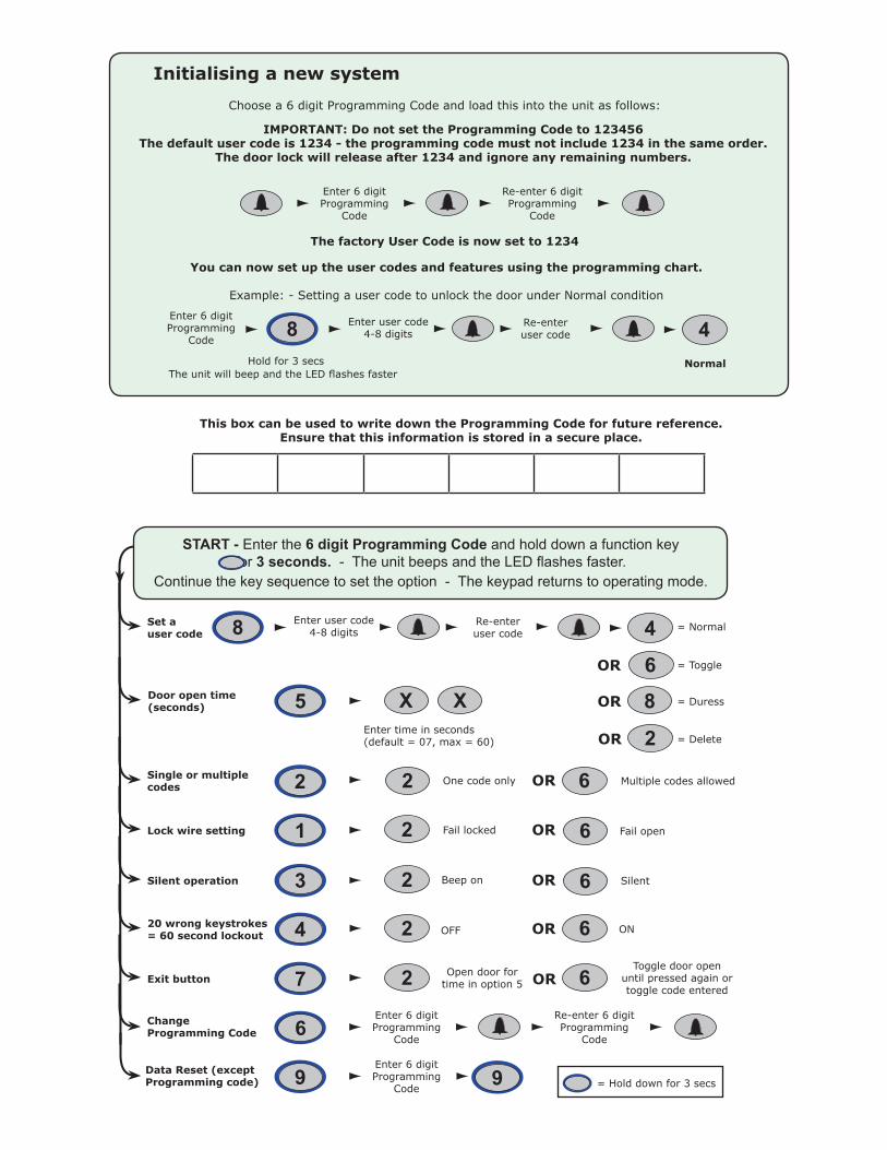
This box can be used to write down the Programming Code for future reference.Ensure that this information is stored in a secure place.
X
Single or multiple codes
Silent operation
20 wrong keystrokes= 60 second lockout
Door open time (seconds)
Change Programming Code
Exit button
Set a user code
Data Reset (except Programming code)
OROne code only Multiple codes allowed
SilentBeep on
OFF ON
Enter time in seconds (default = 07, max = 60)
Open door for time in option 5
Toggle door open until pressed again or toggle code entered
Enter user code4-8 digits
Re-enter user code
Enter 6 digit Programming
Code
= Delete
= Normal
= Toggle
= Duress
Enter 6 digit Programming
Code
Re-enter 6 digit Programming
Code
6
OR
OR
X
OR
2
4
6
8
OR
OR
OR
Lock wire setting Fail locked Fail openOR2
2
2
2
2
2
1
3
4
7
5
6
9
8
6
6
6
6
9
START - Enter the 6 digit Programming Code and hold down a function key for 3 seconds. - The unit beeps and the LED flashes faster.
Continue the key sequence to set the option - The keypad returns to operating mode.
= Hold down for 3 secs
Choose a 6 digit Programming Code and load this into the unit as follows:
IMPORTANT: Do not set the Programming Code to 123456The default user code is 1234 - the programming code must not include 1234 in the same order.
The door lock will release after 1234 and ignore any remaining numbers.
The factory User Code is now set to 1234
Initialising a new system
You can now set up the user codes and features using the programming chart.
Example: - Setting a user code to unlock the door under Normal condition
Enter user code4-8 digits
Re-enter user code 48
Enter 6 digit Programming
Code
Hold for 3 secs The unit will beep and the LED flashes faster
Enter 6 digit Programming
Code
Re-enter 6 digit Programming
Code
Normal

Voltage
Switchable current
1 50
4 digits 8 digits
1 sec 60 secs
11V DC 14V DC
170 mA
1 A
12V DC
-20 °C (-4 °F) +55 °C (+131 °F)
IPX7
K38 1 1/2 in 3 in 1/2 in
K50 2 in 4 in 5/8 in
K75 3 in 5 1/2 in 5/8 in
Specifications
Operating temperature
Electrical
Environment
Dimensions
Min Max
Width Height Depth
Current
Outdoor Use
Features
Number of Codes
Code length
Door open time
Silent operation
Can be used with fail OPEN locksCan be used with fail CLOSED locks
Exit button input
Door Contact input
Alarm/bell output voltage
Waterproof
Backlight
Cable length
Min Max
Min Max
Yes
Yes
Yes
Yes
No
3 yards
1 - Can I use a fail open release (e.g. Maglock)?QThe lock wires from a compact keypad provide 12V DC to the electric lock. By default, the compact is set to operate with a failQlocked release - providing 12V on the lock wires when a valid entry is made. To use a fail open release, the lock wire settingQneeds to be changed (Program option 1)
2 - Can I put a relay across the lock wire output?QYes - All compact systems have been designed to drive relays.
3 - Integration with an entry phone system.QThe output from the entry phone system is used to simulate an exit button for the Paxton equipment. No voltage should beQapplied to the exit input wires (Blue / Mauve) of a compact unit. Most phone systems will provide a powered pair to release theQdoor lock; this voltage must be used to drive an independent relay. The relay contacts must be 'normally open going closed' toQmimic a 'push to make' exit button. Only a voltage free output pair can be connected directly to the exit input wires.
4 - What are the keypad code types used for?QNormal - Releases the door for the time period set in Option 5 ( 7 secs default)QToggle - Releases the lock until the code is entered for a second time.QDuress - Releases the lock (as in Normal) but also energizes the bell output for 30 seconds.QDelete - Used to remove a specific code that has already been entered in Multiple mode.
5 - Connecting a compact with another control unit.QThis cannot be done. Paxton Compact systems have the control electronics built in and no direct data output is provided.QThe Switch2 and Net2 system use a different type of data input.QNote: The compact system will control the door unit on its own.
6- Read in and read out on one door.QYou cannot wire two compact systems in parallel to a common lock as this may result in damage to your system. They will bothQpower the door lock independently and will not offer single point control. We recommend using one Switch2 controller with twoQcompatible keypads or readers.
Here is the list of topics about this product that receive the most technical support inquiries. We list them here to help you speed up the installation and trouble shooting process.
No


![KCIEN KCIENSBP KCIEN/IRC · 1] PRODUCT PRESENTATION Backlit. Stainless steel. Compact design. Compact. 2 relays. Surface mount. Free voltage. Installation with Torx® screws. 100](https://img.pdfslide.net/doc/110x75/5fc43e21618f14339211c1d1/kcien-kciensbp-kcienirc-1-product-presentation-backlit-stainless-steel-compact.jpg)