Embed Size (px)
Citation preview
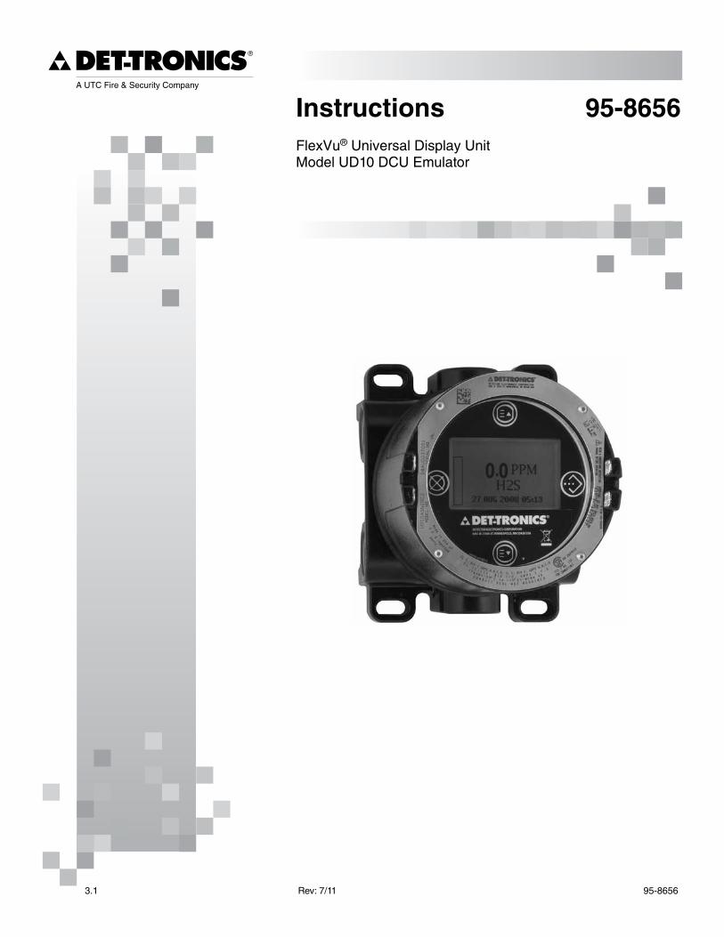
Instructions 95-8656FlexVu® Universal Display UnitModel UD10 DCU Emulator
3.1 Rev: 7/11 95-8656
application . . . . . . . . . . . . . . . . . . . . . . . . . . . . . . 1
DEScRiption . . . . . . . . . . . . . . . . . . . . . . . . . . . . . . 1
Magnetic Switches . . . . . . . . . . . . . . . . . . . . . . . . 2Device Enclosure . . . . . . . . . . . . . . . . . . . . . . . . . 3Device Display . . . . . . . . . . . . . . . . . . . . . . . . . . . 3configuration overview . . . . . . . . . . . . . . . . . . . . 3alarms . . . . . . . . . . . . . . . . . . . . . . . . . . . . . . . . . 4calibration Gas concentration . . . . . . . . . . . . . . . 4logging . . . . . . . . . . . . . . . . . . . . . . . . . . . . . . . . . 5
iMpoRtant SaFEtY notES . . . . . . . . . . . . . . . . . . . 5
inStallation . . . . . . . . . . . . . . . . . . . . . . . . . . . . . . 6
identification of Vapor(s) to be Detected . . . . . . . . . 6
identification of Detector Mounting locations . . . . . 6
WiRinG . . . . . . . . . . . . . . . . . . . . . . . . . . . . . . . . . . . . 7
power Supply Requirements . . . . . . . . . . . . . . . . . 7Wiring cable Requirements . . . . . . . . . . . . . . . . . . 7Wiring procedure . . . . . . . . . . . . . . . . . . . . . . . . . . 7Shield connections . . . . . . . . . . . . . . . . . . . . . . . 7lon address Switch Setting . . . . . . . . . . . . . . . . 9
REcoMMEnDED StaRtUp pRocEDURE . . . . . . . . 9
S3 conFiGURation . . . . . . . . . . . . . . . . . . . . . . . 10
tRoUblEShootinG . . . . . . . . . . . . . . . . . . . . . . . 15
SpEciFicationS . . . . . . . . . . . . . . . . . . . . . . . . . . . 18
DEVicE REpaiR anD REtURn . . . . . . . . . . . . . . . 20
oRDERinG inFoRMation . . . . . . . . . . . . . . . . . . 20
appEnDiX a — FM appRoVal DEScRiption . . . . a-1
appEnDiX b — cSa cERtiFication DEScRiption . b-1
appEnDiX c — atEX appRoVal DEScRiption . . . . . c-1
appEnDiX D — iEc appRoVal DEScRiption . . . . . . D-1
appEnDiX E — UD10-DcU With Gt3000 . . . . . . . E-1
Wiring . . . . . . . . . . . . . . . . . . . . . . . . . . . . . . . . E-1orientation . . . . . . . . . . . . . . . . . . . . . . . . . . . . E-2live Maintenance . . . . . . . . . . . . . . . . . . . . . . . E-2calibration . . . . . . . . . . . . . . . . . . . . . . . . . . . . E-3Menu Structure . . . . . . . . . . . . . . . . . . . . . . . . . E-4
appEnDiX F — UD10-DcU With piR9400 . . . . . . . . . . F-1
Wiring . . . . . . . . . . . . . . . . . . . . . . . . . . . . . . . . F-1installation notes . . . . . . . . . . . . . . . . . . . . . . . F-2orientation . . . . . . . . . . . . . . . . . . . . . . . . . . . . F-2changing operating Modes . . . . . . . . . . . . . . . F-3calibration . . . . . . . . . . . . . . . . . . . . . . . . . . . . F-3Menu Structure . . . . . . . . . . . . . . . . . . . . . . . . . F-3
appEnDiX G — UD10-DcU With MoDEl piREcl . . .G-1
Wiring . . . . . . . . . . . . . . . . . . . . . . . . . . . . . . . . G-1orientation . . . . . . . . . . . . . . . . . . . . . . . . . . . . G-2calibration . . . . . . . . . . . . . . . . . . . . . . . . . . . . G-3Menu Structure . . . . . . . . . . . . . . . . . . . . . . . . . G-4
appEnDiX h — UD10-DcU With MoDEl opEcl h-1
Wiring . . . . . . . . . . . . . . . . . . . . . . . . . . . . . . . . h-1orientation . . . . . . . . . . . . . . . . . . . . . . . . . . . . h-3calibration . . . . . . . . . . . . . . . . . . . . . . . . . . . . h-3opEcl transmitter lamp Fault condition . . . . h-4Menu Structure . . . . . . . . . . . . . . . . . . . . . . . . . h-4
appEnDiX i — UD10-DcU With ntMoS h2S SEnSoR . . i-1
Wiring . . . . . . . . . . . . . . . . . . . . . . . . . . . . . . . . . i-1installation notes . . . . . . . . . . . . . . . . . . . . . . . . i-1orientation . . . . . . . . . . . . . . . . . . . . . . . . . . . . . i-3calibration . . . . . . . . . . . . . . . . . . . . . . . . . . . . . i-3Menu Structure . . . . . . . . . . . . . . . . . . . . . . . . . . i-4
appEnDiX J — UD10-DcU With c706X GaS SEnSoR . . J-1
Wiring . . . . . . . . . . . . . . . . . . . . . . . . . . . . . . . . J-1installation . . . . . . . . . . . . . . . . . . . . . . . . . . . . J-3calibration . . . . . . . . . . . . . . . . . . . . . . . . . . . . J-4Menu Structure . . . . . . . . . . . . . . . . . . . . . . . . . J-4
appEnDiX K — UD10-DcU With MoDEl cGS SEnSoR . .K-1
Wiring . . . . . . . . . . . . . . . . . . . . . . . . . . . . . . . .K-1important notes . . . . . . . . . . . . . . . . . . . . . . . .K-1installation . . . . . . . . . . . . . . . . . . . . . . . . . . . . .K-3calibration . . . . . . . . . . . . . . . . . . . . . . . . . . . . .K-4K-Factor . . . . . . . . . . . . . . . . . . . . . . . . . . . . . . .K-4Menu Structure . . . . . . . . . . . . . . . . . . . . . . . . .K-4
appEnDiX l — UD10-DcU With MoDEl 505/cGS . . l-1
Wiring . . . . . . . . . . . . . . . . . . . . . . . . . . . . . . . . l-1installation . . . . . . . . . . . . . . . . . . . . . . . . . . . . l-2orientation . . . . . . . . . . . . . . . . . . . . . . . . . . . . l-2calibration . . . . . . . . . . . . . . . . . . . . . . . . . . . . l-3Menu Structure . . . . . . . . . . . . . . . . . . . . . . . . . l-4
appEnDiX M — UD10-DcU With GEnERic 4-20 Ma SEnSoR . M-1
operation . . . . . . . . . . . . . . . . . . . . . . . . . . . . .M-1Menu Structure . . . . . . . . . . . . . . . . . . . . . . . . .M-1
Table of Contents
INSTRUCTIONS
FlexVu® Universal Display Unit
Model UD10 DCU Emulator
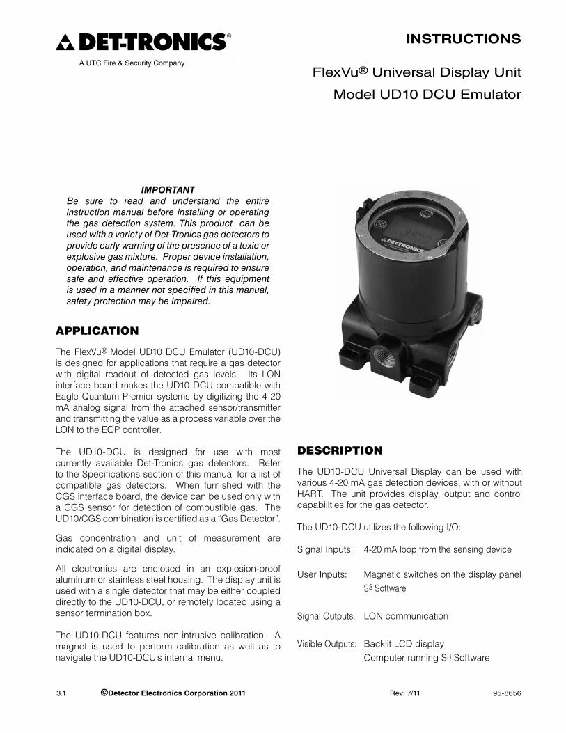
ImportantBe sure to read and understand the entire instruction manual before installing or operating the gas detection system. This product can be used with a variety of Det-Tronics gas detectors to provide early warning of the presence of a toxic or explosive gas mixture. Proper device installation, operation, and maintenance is required to ensure safe and effective operation. If this equipment is used in a manner not specified in this manual, safety protection may be impaired.
ApplicAtion
The FlexVu® Model UD10 DCU Emulator (UD10-DCU) is designed for applications that require a gas detector with digital readout of detected gas levels. Its LON interface board makes the UD10-DCU compatible with Eagle Quantum Premier systems by digitizing the 4-20 mA analog signal from the attached sensor/transmitter and transmitting the value as a process variable over the LON to the EQP controller.
The UD10-DCU is designed for use with most currently available Det-Tronics gas detectors. Refer to the Specifications section of this manual for a list of compatible gas detectors. When furnished with the CGS interface board, the device can be used only with a CGS sensor for detection of combustible gas. The UD10/CGS combination is certified as a “Gas Detector”.
Gas concentration and unit of measurement are indicated on a digital display.
All electronics are enclosed in an explosion-proof aluminum or stainless steel housing. The display unit is used with a single detector that may be either coupled directly to the UD10-DCU, or remotely located using a sensor termination box.
The UD10-DCU features non-intrusive calibration. A magnet is used to perform calibration as well as to navigate the UD10-DCU’s internal menu.
Description
The UD10-DCU Universal Display can be used with various 4-20 mA gas detection devices, with or without HART. The unit provides display, output and control capabilities for the gas detector.
The UD10-DCU utilizes the following I/O:
Signal Inputs: 4-20 mA loop from the sensing device
User Inputs: Magnetic switches on the display panel S3 Software
Signal Outputs: LON communication
Visible Outputs: Backlit LCD display Computer running S3 Software
3.1 ©Detector Electronics Corporation 2011 Rev: 7/11 95-8656
2 95-86563.1
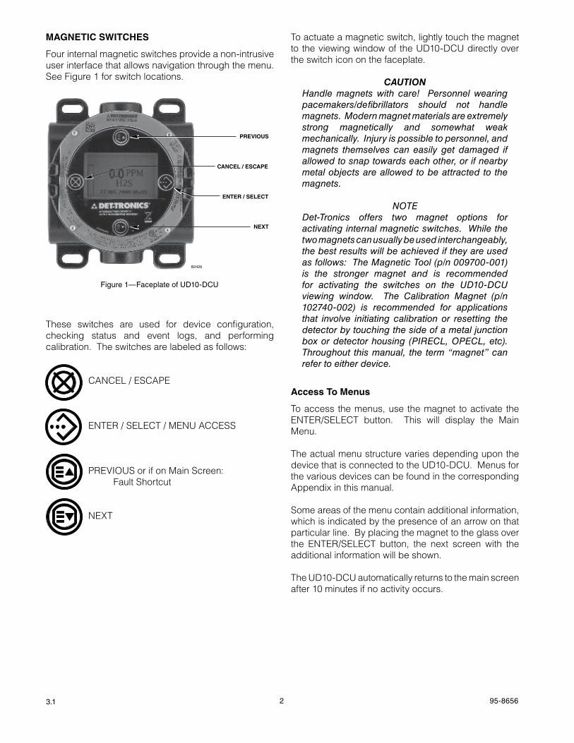
magNETIC SwITChES
Four internal magnetic switches provide a non-intrusive user interface that allows navigation through the menu. See Figure 1 for switch locations.
These switches are used for device configuration, checking status and event logs, and performing calibration. The switches are labeled as follows:
CANCEL / ESCAPE
ENTER / SELECT / MENU ACCESS
PREVIOUS or if on Main Screen: Fault Shortcut
NExT
To actuate a magnetic switch, lightly touch the magnet to the viewing window of the UD10-DCU directly over the switch icon on the faceplate.
CautIonHandle magnets with care! Personnel wearing pacemakers/defibrillators should not handle magnets. Modern magnet materials are extremely strong magnetically and somewhat weak mechanically. Injury is possible to personnel, and magnets themselves can easily get damaged if allowed to snap towards each other, or if nearby metal objects are allowed to be attracted to the magnets.
noTeDet-Tronics offers two magnet options for activating internal magnetic switches. While the two magnets can usually be used interchangeably, the best results will be achieved if they are used as follows: The Magnetic Tool (p/n 009700-001) is the stronger magnet and is recommended for activating the switches on the UD10-DCU viewing window. The Calibration Magnet (p/n 102740-002) is recommended for applications that involve initiating calibration or resetting the detector by touching the side of a metal junction box or detector housing (PIReCL, oPeCL, etc). Throughout this manual, the term “magnet” can refer to either device.
access To menus
To access the menus, use the magnet to activate the ENTER/SELECT button. This will display the Main Menu.
The actual menu structure varies depending upon the device that is connected to the UD10-DCU. Menus for the various devices can be found in the corresponding Appendix in this manual.
Some areas of the menu contain additional information, which is indicated by the presence of an arrow on that particular line. By placing the magnet to the glass over the ENTER/SELECT button, the next screen with the additional information will be shown.
The UD10-DCU automatically returns to the main screen after 10 minutes if no activity occurs.
CANCEL / ESCAPE
ENTER / SELECT
PREVIOUS
NEXT
B2426
Figure 1—Faceplate of UD10-DCU
3 95-86563.1
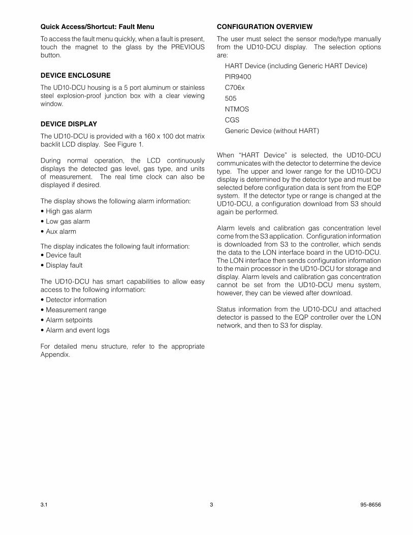
Quick access/Shortcut: Fault menu
To access the fault menu quickly, when a fault is present, touch the magnet to the glass by the PREVIOUS button.
DEvICE ENCLOSURE
The UD10-DCU housing is a 5 port aluminum or stainless steel explosion-proof junction box with a clear viewing window.
DEvICE DISPLaY
The UD10-DCU is provided with a 160 x 100 dot matrix backlit LCD display. See Figure 1.
During normal operation, the LCD continuously displays the detected gas level, gas type, and units of measurement. The real time clock can also be displayed if desired.
The display shows the following alarm information:•Highgasalarm•Lowgasalarm•Auxalarm
The display indicates the following fault information:•Devicefault•Displayfault
The UD10-DCU has smart capabilities to allow easy access to the following information:•Detectorinformation•Measurementrange•Alarmsetpoints•Alarmandeventlogs
For detailed menu structure, refer to the appropriate Appendix.
CONFIgURaTION OvERvIEw
The user must select the sensor mode/type manually from the UD10-DCU display. The selection options are:
HART Device (including Generic HART Device)
PIR9400
C706x
505
NTMOS
CGS
Generic Device (without HART)
When “HART Device” is selected, the UD10-DCU communicates with the detector to determine the device type. The upper and lower range for the UD10-DCU display is determined by the detector type and must be selected before configuration data is sent from the EQP system. If the detector type or range is changed at the UD10-DCU, a configuration download from S3 should again be performed.
Alarm levels and calibration gas concentration level come from the S3 application. Configuration information is downloaded from S3 to the controller, which sends the data to the LON interface board in the UD10-DCU. The LON interface then sends configuration information to the main processor in the UD10-DCU for storage and display. Alarm levels and calibration gas concentration cannot be set from the UD10-DCU menu system, however, they can be viewed after download.
Status information from the UD10-DCU and attached detector is passed to the EQP controller over the LON network, and then to S3 for display.
4 95-86563.1
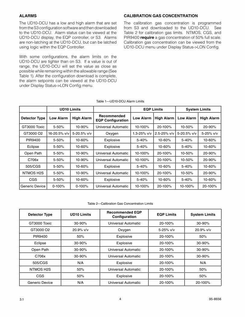
aLaRmS
The UD10-DCU has a low and high alarm that are set from the S3 configuration software and then downloaded to the UD10-DCU. Alarm status can be viewed at the UD10-DCU display, the EQP controller, or S3. Alarms are non-latching at the UD10-DCU, but can be latched using logic within the EQP Controller.
With some configurations, the alarm limits on the UD10-DCU are tighter than on S3. If a value is out of range, the UD10-DCU will set the value as close as possible while remaining within the allowable range (See Table 1). After the configuration download is complete, the alarm setpoints can be viewed at the UD10-DCU under Display Status->LON Config menu.
CaLIbRaTION gaS CONCENTRaTION
The calibration gas concentration is programmed from S3 and downloaded to the UD10-DCU. See Table 2 for calibration gas limits. NTMOS, CGS, and PIR9400 require a gas concentration of 50% full scale. Calibration gas concentration can be viewed from the UD10-DCU menu under Display Status->LON Config.
UD10 Limits EQP Limits System Limits
Detector Type Low alarm high alarmRecommended
EQP ConfigurationLow alarm high alarm Low alarm high alarm
GT3000 Toxic 5-50% 10-90% Universal Automatic 10-100% 20-100% 10-50% 20-90%
GT3000 O2 16-20.5% v/v 5-20.5% v/v Oxygen 1.3-25% v/v 2.5-25% v/v 5-20.5% v/v 5-25% v/v
PIR9400 5-50% 10-60% Explosive 5-40% 10-60% 5-40% 10-60%
Eclipse 5-50% 10-60% Explosive 5-40% 10-60% 5-40% 10-60%
Open Path 5-50% 10-90% Universal Automatic 10-100% 20-100% 10-50% 20-90%
C706x 5-50% 10-90% Universal Automatic 10-100% 20-100% 10-50% 20-90%
505/CGS 5-50% 10-60% Explosive 5-40% 10-60% 5-40% 10-60%
NTMOS H2S 5-50% 10-90% Universal Automatic 10-100% 20-100% 10-50% 20-90%
CGS 5-50% 10-60% Explosive 5-40% 10-60% 5-40% 10-60%
Generic Device 0-100% 0-100% Universal Automatic 10-100% 20-100% 10-100% 20-100%
Table 1—UD10-DCU Alarm Limits
Detector Type UD10 LimitsRecommended EQP
ConfigurationEQP Limits System Limits
GT3000 Toxic 30-90% Universal Automatic 20-100% 30-90%
GT3000 O2 20.9% v/v Oxygen 5-25% v/v 20.9% v/v
PIR9400 50% Explosive 20-100% 50%
Eclipse 30-90% Explosive 20-100% 30-90%
Open Path 30-90% Universal Automatic 20-100% 30-90%
C706x 30-90% Universal Automatic 20-100% 30-90%
505/CGS N/A Explosive 20-100% N/A
NTMOS H2S 50% Universal Automatic 20-100% 50%
CGS 50% Explosive 20-100% 50%
Generic Device N/A Universal Automatic 20-100% 20-100%
Table 2—Calibration Gas Concentration Limits
5 95-86563.1
LOggINg
Events that can be logged in the UD10-DCU include:
•Calibration(Date, timeandsuccessY/Nare loggedfor detectors that do not provide their own calibration logging capabilities.)
Faults that are logged in the UD10-DCU include:
•Detectorfault
•Lowpower
•Generalfault
Alarms that are logged in the UD10-DCU for gas detector inputs include:
•Highgasalarm
•Lowgasalarm.
The UD10-DCU can display the detector event and calibration logs (if available). Detector calibration and event logs can also be read from the detector’s HART interface (where available).
The UD10-DCU has its own 1,000-entry event log available under the Display Status->History->Event Log menu.
The LON interface board in the UD10-DCU has eight alarm logs and eight calibration logs. These logs are available from the S3 “Point Display Screen” for the UD10-DCU.
The EQP Controller and S3 also maintain their own logs. Refer to the EQP system manual (95-8533) and/or the S3 manual (95-8560) for details.
importAnt sAfety notes
CautIonThe wiring procedures in this manual are intended to ensure proper functioning of the device under normal conditions. However, because of the many variations in wiring codes and regulations, total compliance to these ordinances cannot be guaranteed. Be certain that all wiring complies with the neC as well as all local codes. If in doubt, consult the authority having jurisdiction before wiring the system. Installation must be done by a properly trained person.
CautIonThis product has been tested and approved for use in hazardous areas. However, it must be properly installed and used only under the conditions specified within this manual and the specific approval certificates. Any device modification, improper installation, or use in a faulty or incomplete configuration will render warranty and product certifications invalid.
CautIonThe device contains no user serviceable components. Service or repair should never be attempted by the user. Device repair should be performed only by the manufacturer.
LIabILItIesThe manufacturer’s warranty for this product is void, and all liability for proper function of the detector is irrevocably transferred to the owner or operator in the event that the device is serviced or repaired by personnel not employed or authorized by Detector electronics Corporation, or if the device is used in a manner not conforming to its intended use.
CautIonobserve precautions for handling electrostatic sensitive devices.
CautIonUnused conduit entries must be closed with suitably certified blanking elements upon installation.
6 95-86563.1
instAllAtion
noTeFor complete instructions regarding wiring, installation, and use of the eagle Quantum Premier system, refer to manual number 95-8533.
noTeThe gas detector housing must be electrically connected to earth ground. A dedicated earth ground terminal is provided on the UD10-DCU.
The detector must always be installed per local installation codes.
Before installing the gas detector, define the following application details:
IDENTIFICaTION OF vaPOR(S) TO bE DETECTED
It is necessary to identify the vapor(s) of interest at the job site. The fire hazard properties of the vapor, such as vapor density, flashpoint, and vapor pressure should be identified and used to assist in selecting the optimum detector mounting location within the area.
For cross sensitivity information, refer to each gas detector’s corresponding instruction manual. Refer to the Specifications section in this manual for a list of gas detectors and their corresponding instruction manuals.
IDENTIFICaTION OF DETECTOR mOUNTINg LOCaTIONS
Identification of the most likely leak sources and leak accumulation areas is typically the first step in identifying the best detector mounting locations. In addition, identification of air current/wind patterns within the protected area is useful in predicting gas leak dispersion behavior. This information should be used to identify optimum detector installation points.
If the vapor of interest is lighter than air, place the detector above the potential gas leak. Place the detector close to the floor for gases that are heavier than air. Note that air currents may cause a gas that is slightly heavier than air to rise under some conditions. Heated gases may also exhibit the same phenomenon.
The most effective number and placement of detectors varies depending on the conditions on site. The individual designing the installation must often rely on experience and common sense to determine the detector quantity and best locations to adequately protect the area. Note that it is typically advantageous to locate detectors where they are accessible for maintenance. Locations near excessive heat or vibration sources should be avoided.
Final suitability of possible gas detector locations should be verified by a job site survey.
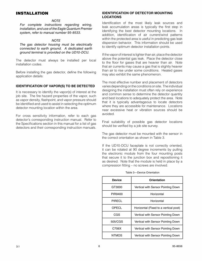
The gas detector must be mounted with the sensor in the correct orientation as shown in Table 3.
If the UD10-DCU faceplate is not correctly oriented, it can be rotated at 90 degree increments by pulling the electronic module from the four mounting posts that secure it to the junction box and repositioning it as desired. Note that the module is held in place by a compression fitting – no screws are involved.
Table 3—Device Orientation
Device Orientation
GT3000 Vertical with Sensor Pointing Down
PIR9400 Horizontal
PIRECL Horizontal
OPECL Horizontal (Fixed to a vertical post)
CGS Vertical with Sensor Pointing Down
505/CGS Vertical with Sensor Pointing Down
C706X Vertical with Sensor Pointing Down
NTMOS Vertical with Sensor Pointing Down
7 95-86563.1
WirinG
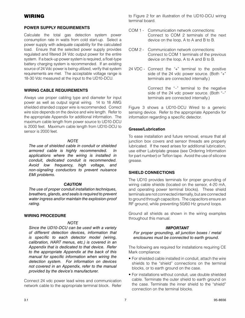
POwER SUPPLY REQUIREmENTS
Calculate the total gas detection system power consumption rate in watts from cold start-up. Select a power supply with adequate capability for the calculated load. Ensure that the selected power supply provides regulated and filtered 24 Vdc output power for the entire system. If a back-up power system is required, a float-type battery charging system is recommended. If an existing source of 24 Vdc power is being utilized, verify that system requirements are met. The acceptable voltage range is 18-30 Vdc measured at the input to the UD10-DCU.
wIRINg CabLE REQUIREmENTS
Always use proper cabling type and diameter for input power as well as output signal wiring. 14 to 18 AWG shielded stranded copper wire is recommended. Correct wire size depends on the device and wire length. Refer to the appropriate Appendix for additional information. The maximum cable length from power source to UD10-DCU is 2000 feet. Maximum cable length from UD10-DCU to sensor is 2000 feet.
noTeThe use of shielded cable in conduit or shielded armored cable is highly recommended. In applications where the wiring is installed in conduit, dedicated conduit is recommended. Avoid low frequency, high voltage, and non-signaling conductors to prevent nuisance eMI problems.
CautIonThe use of proper conduit installation techniques, breathers, glands, and seals is required to prevent water ingress and/or maintain the explosion-proof rating.
wIRINg PROCEDURE
noTeSince the UD10-DCU can be used with a variety of different detection devices, information that is specific to each detector model (wiring, calibration, HART menus, etc.) is covered in an Appendix that is dedicated to that device. Refer to the appropriate Appendix at the back of this manual for specific information when wiring the detection system. For information on devices not covered in an Appendix, refer to the manual provided by the device’s manufacturer.
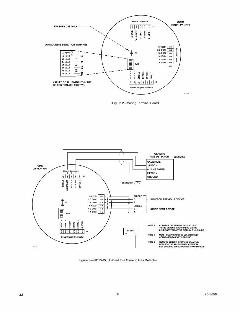
Connect 24 vdc power lead wires and communication network cable to the appropriate terminal block. Refer
to Figure 2 for an illustration of the UD10-DCU wiring terminal board.
COM 1 - Communication network connections: Connect to COM 2 terminals of the next
device on the loop, A to A and B to B.
COM 2 - Communication network connections: Connect to COM 1 terminals of the previous
device on the loop, A to A and B to B.
24 VDC - Connect the “+” terminal to the positive side of the 24 vdc power source. (Both “+” terminals are connected internally.)
Connect the “–” terminal to the negative side of the 24 vdc power source. (Both “–” terminals are connected internally.)
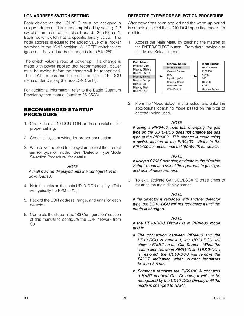
Figure 3 shows a UD10-DCU Wired to a generic sensing device. Refer to the appropriate Appendix for information regarding a specific detector.
grease/Lubrication
To ease installation and future removal, ensure that all junction box covers and sensor threads are properly lubricated. If the need arises for additional lubrication, use either Lubriplate grease (see Ordering Information for part number) or Teflon tape. Avoid the use of silicone grease.
ShIELD CONNECTIONS
The UD10 provides terminals for proper grounding of wiring cable shields (located on the sensor, 4-20 mA, and operating power terminal blocks). These shield terminals are not connected internally, but are connected to ground through capacitors. The capacitors ensure an RF ground, while preventing 50/60 Hz ground loops.
Ground all shields as shown in the wiring examples throughout this manual.
ImportantFor proper grounding, all junction boxes / metal enclosures must be connected to earth ground.
The following are required for installations requiring CE Mark compliance:
•Forshieldedcableinstalledinconduit,attachthewireshields to the “shield” connections on the terminal blocks, or to earth ground on the case.
•Forinstallationswithoutconduit,usedoubleshieldedcable. Terminate the outer shield to earth ground on the case. Terminate the inner shield to the “shield” connection on the terminal blocks.
8 95-86563.1
Sensor Connector
Power Supply Connector
LON
Co
nn
ecto
r
J4
J3
J7
24 V
DC
–
24 V
DC
+
SH
IEL
D
24 V
DC
–
24 V
DC
+
SH
IEL
D
SH
IEL
D
CA
LIB
RA
TE
24 V
DC
–
4-20
mA
24 V
DC
+
J4-1
J4-2
J4-3
J4-4
J4-5
J7-6
J7-5
J7-4
J7-3
J7-2
J7-1
SHIELD
2 B COM
2 A COM
SHIELD
1 B COM
1 A COM
J3-1
J3-2
J3-3
J3-4
J3-5
J3-6
UD10 DISPLAY UNIT
A2509
SW3
J2
ON
21
34
56
78
ON 1
2
4
8
16 3264 128
VALUES OF ALL SWITCHES IN THE ON POSITION ARE ADDITIVE.
LON ADDRESS SELECTION SWITCHES
FACTORY USE ONLY
Figure 2—Wiring Terminal Board
Sensor Connector
Power Supply Connector
LON
Co
nn
ecto
r
J4
J3
J7
24 V
DC
–
24 V
DC
+
SH
IEL
D
24 V
DC
–
24 V
DC
+
SH
IEL
D
SH
IEL
D
CA
LIB
RA
TE
24 V
DC
–
4-20
mA
24 V
DC
+
J4-1
J4-2
J4-3
J4-4
J4-5
J7-6
J7-5
J7-4
J7-3
J7-2
J7-1
SHIELD
2 B COM
2 A COM
SHIELD
1 B COM
1 A COM
J3-1
J3-2
J3-3
J3-4
J3-5
J3-6
UD10 DISPLAY UNIT
A2510
SW3
J2
ON
BSHIELD
SHIELD
A
BA
LON FROM PREVIOUS DEVICE
LON TO NEXT DEVICE
24 VDC–+
GENERICGAS DETECTOR
24 VDC –
24 VDC +
CALIBRATE
4-20 MA SIGNAL
GROUND
SEE NOTE 1
SEE NOTE 3
NOTE 1 CONNECT THE SENSOR GROUND LEAD TO THE CHASSIS GROUND LUG ON THE INSIDE BOTTOM OF THE DISPLAY ENCLOSURE.
NOTE 2 UD10 HOUSING MUST BE ELECTRICALLY CONNECTED TO EARTH GROUND.
NOTE 3 GENERIC SENSOR SHOWN AS EXAMPLE. REFER TO THE APPROPRIATE APPENDIX FOR SPECIFIC SENSOR WIRING INFORMATION.
Figure 3—UD10-DCU Wired to a Generic Gas Detector
9 95-86563.1
LON aDDRESS SwITCh SETTINg
Each device on the LON/SLC must be assigned a unique address. This is accomplished by setting DIP switches on the module’s circuit board. See Figure 2. Each rocker switch has a specific binary value. The node address is equal to the added value of all rocker switches in the “ON” position. All “OFF” switches are ignored. The valid address range is from 5 to 250.
The switch value is read at power-up. If a change is made with power applied (not recommended), power must be cycled before the change will be recognized. The LON address can be read from the UD10-DCU menu under Display Status->LON Config.
For additional information, refer to the Eagle Quantum Premier system manual (number 95-8533).
recommenDeD stArtup proceDure
1. Check the UD10-DCU LON address switches for proper setting.
2. Check all system wiring for proper connection.
3. With power applied to the system, select the correct sensor type or mode. See “Detector Type/Mode Selection Procedure” for details.
noTeA fault may be displayed until the configuration is downloaded.
4. Note the units on the main UD10-DCU display. (This will typically be PPM or %.)
5. Record the LON address, range, and units for each detector.
6. Complete the steps in the “S3 Configuration” section of this manual to configure the LON network from S3.
DETECTOR TYPE/mODE SELECTION PROCEDURE
After power has been applied and the warm-up period is complete, select the UD10-DCU operating mode. To do this:
1. Access the Main Menu by touching the magnet to the ENTER/SELECT button. From there, navigate to the “Mode Select” menu.
Main MenuProcess VarsDisplay StatusDevice StatusDisplay SetupDevice SetupDevice CalDisplay TestDevice Test
Display SetupMode Select
General Options
RTC
Input Loop Cal
Contrast Contrl
Backlight Ctrl
Write Protect
Mode SelectHART Device
PIR9400
C706X
505
NTMOS
CGS
Generic Device
2. From the “Mode Select” menu, select and enter the appropriate operating mode based on the type of detector being used.
noTeIf using a PIR9400, note that changing the gas type on the UD10-DCU does not change the gas type at the PIR9400. This change is made using a switch located in the PIR9400. Refer to the PIR9400 instruction manual (95-8440) for details.
noTeIf using a C706X detector, navigate to the “Device Setup” menu and select the appropriate gas type and unit of measurement.
3. To exit, activate CANCEL/ESCAPE three times to return to the main display screen.
noTeIf the detector is replaced with another detector type, the UD10-DCU will not recognize it until the mode is changed.
noTeIf the UD10-DCU Display is in PIR9400 mode and if:
a. The connection between PIR9400 and the UD10-DCU is removed, the UD10-DCU will show a FAULT on the Gas Screen. When the connection between PIR9400 and UD10-DCU is restored, the UD10-DCU will remove the FAULT indication when current increases beyond 3.6 mA.
b. Someone removes the PIR9400 & connects a HART enabled Gas Detector, it will not be recognized by the UD10-DCU Display until the mode is changed to HART.
10 95-86563.1
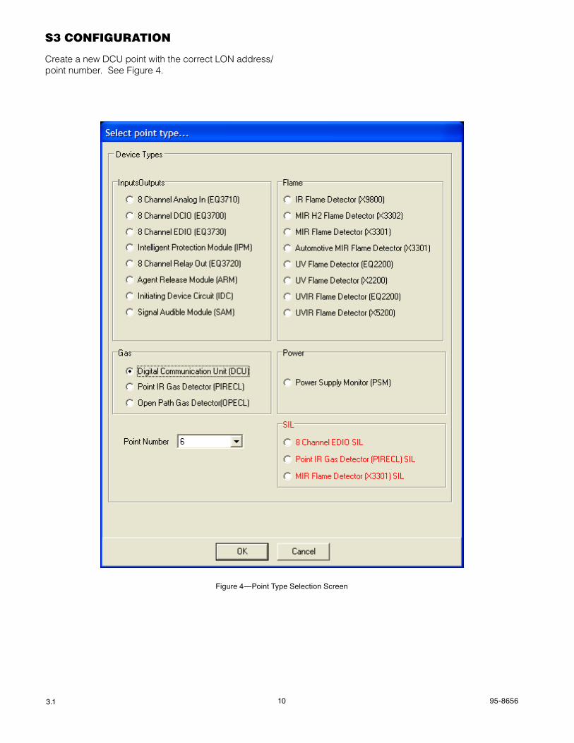
s3 confiGurAtion
Create a new DCU point with the correct LON address/point number. See Figure 4.
Figure 4—Point Type Selection Screen
11 95-86563.1
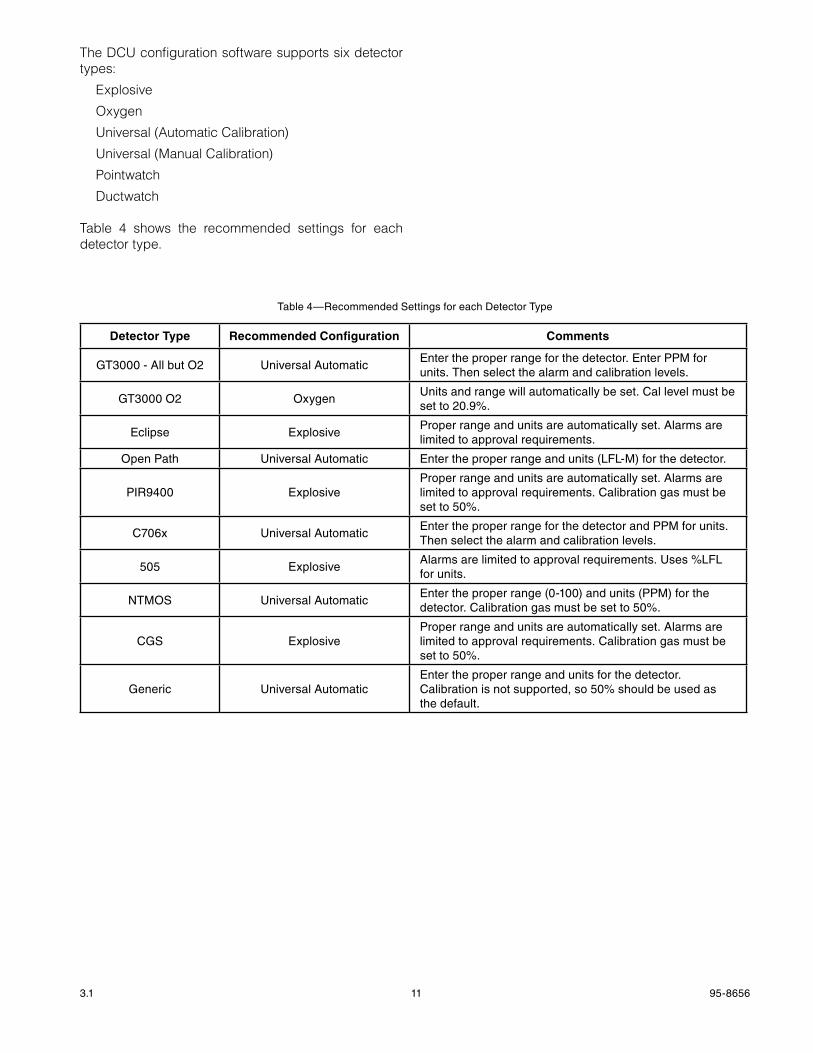
The DCU configuration software supports six detector types:
Explosive
Oxygen
Universal (Automatic Calibration)
Universal (Manual Calibration)
Pointwatch
Ductwatch
Table 4 shows the recommended settings for each detector type.
Detector Type Recommended Configuration Comments
GT3000 - All but O2 Universal AutomaticEnter the proper range for the detector. Enter PPM for units. Then select the alarm and calibration levels.
GT3000 O2 OxygenUnits and range will automatically be set. Cal level must be set to 20.9%.
Eclipse ExplosiveProper range and units are automatically set. Alarms are limited to approval requirements.
Open Path Universal Automatic Enter the proper range and units (LFL-M) for the detector.
PIR9400 ExplosiveProper range and units are automatically set. Alarms are limited to approval requirements. Calibration gas must be set to 50%.
C706x Universal AutomaticEnter the proper range for the detector and PPM for units. Then select the alarm and calibration levels.
505 ExplosiveAlarms are limited to approval requirements. Uses %LFL for units.
NTMOS Universal AutomaticEnter the proper range (0-100) and units (PPM) for the detector. Calibration gas must be set to 50%.
CGS ExplosiveProper range and units are automatically set. Alarms are limited to approval requirements. Calibration gas must be set to 50%.
Generic Universal AutomaticEnter the proper range and units for the detector. Calibration is not supported, so 50% should be used as the default.
Table 4—Recommended Settings for each Detector Type
12 95-86563.1
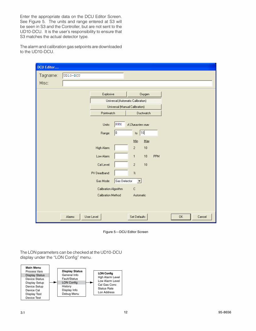
Enter the appropriate data on the DCU Editor Screen. See Figure 5. The units and range entered at S3 will be seen in S3 and the Controller, but are not sent to the UD10-DCU. It is the user’s responsibility to ensure that S3 matches the actual detector type.
The alarm and calibration gas setpoints are downloaded to the UD10-DCU.
The LON parameters can be checked at the UD10-DCU display under the “LON Config” menu.
Display StatusGeneral InfoFault/StatusLON ConfigHistoryDisplay InfoDebug Menu
LON ConfigHgh Alarm LevelLow Alarm LevelCal Gas ConcStatus RateLon Address
Main MenuProcess VarsDisplay StatusDevice StatusDisplay SetupDevice SetupDevice CalDisplay TestDevice Test
Figure 5—DCU Editor Screen
13 95-86563.1
RTC
Time and date for the UD10-DCU is automatically set by the EQP controller via the LON network. Changes to the time on the S3 computer will be reflected at the UD10-DCU when the controller RTC is set.
When used with the GT3000, the RTC for the GT3000 can be synchronized to the RTC of the display by going through the Main Menu->Device Setup->RTC->“Sync W/Disp”.
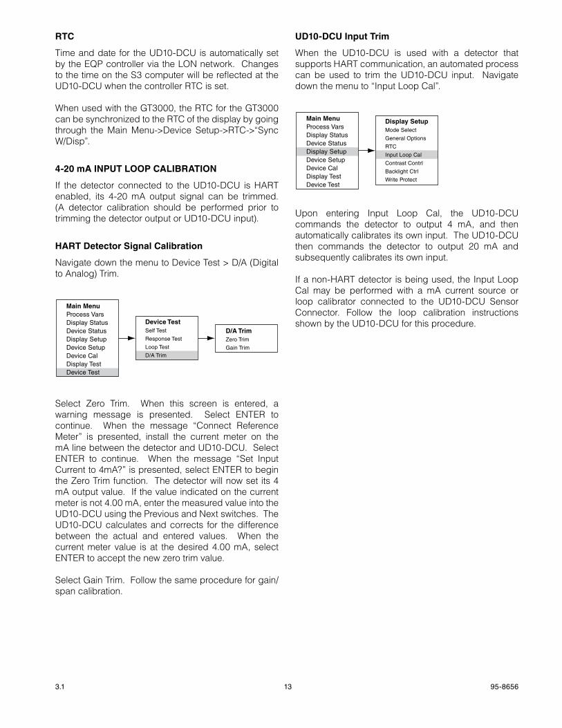
4-20 ma INPUT LOOP CaLIbRaTION
If the detector connected to the UD10-DCU is HART enabled, its 4-20 mA output signal can be trimmed. (A detector calibration should be performed prior to trimming the detector output or UD10-DCU input).
haRT Detector Signal Calibration
Navigate down the menu to Device Test > D/A (Digital to Analog) Trim.
Main MenuProcess VarsDisplay StatusDevice StatusDisplay SetupDevice SetupDevice CalDisplay TestDevice Test
Device TestSelf Test
Response Test
Loop Test
D/A Trim
D/A TrimZero Trim
Gain Trim
Select Zero Trim. When this screen is entered, a warning message is presented. Select ENTER to continue. When the message “Connect Reference Meter” is presented, install the current meter on the mA line between the detector and UD10-DCU. Select ENTER to continue. When the message “Set Input Current to 4mA?” is presented, select ENTER to begin the Zero Trim function. The detector will now set its 4 mA output value. If the value indicated on the current meter is not 4.00 mA, enter the measured value into the UD10-DCU using the Previous and Next switches. The UD10-DCU calculates and corrects for the difference between the actual and entered values. When the current meter value is at the desired 4.00 mA, select ENTER to accept the new zero trim value.
Select Gain Trim. Follow the same procedure for gain/span calibration.
UD10-DCU Input Trim
When the UD10-DCU is used with a detector that supports HART communication, an automated process can be used to trim the UD10-DCU input. Navigate down the menu to “Input Loop Cal”.
Main MenuProcess VarsDisplay StatusDevice StatusDisplay SetupDevice SetupDevice CalDisplay TestDevice Test
Display SetupMode Select
General Options
RTC
Input Loop Cal
Contrast Contrl
Backlight Ctrl
Write Protect
Upon entering Input Loop Cal, the UD10-DCU commands the detector to output 4 mA, and then automatically calibrates its own input. The UD10-DCU then commands the detector to output 20 mA and subsequently calibrates its own input.
If a non-HART detector is being used, the Input Loop Cal may be performed with a mA current source or loop calibrator connected to the UD10-DCU Sensor Connector. Follow the loop calibration instructions shown by the UD10-DCU for this procedure.
14 95-86563.1
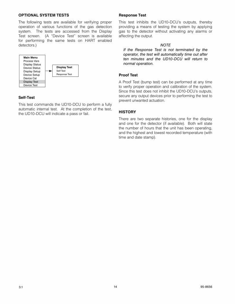
OPTIONaL SYSTEm TESTS
The following tests are available for verifying proper operation of various functions of the gas detection system. The tests are accessed from the Display Test screen. (A “Device Test” screen is available for performing the same tests on HART enabled detectors.)
Main MenuProcess VarsDisplay StatusDevice StatusDisplay SetupDevice SetupDevice CalDisplay TestDevice Test
Display TestSelf Test
Response Test
Self-Test
This test commands the UD10-DCU to perform a fully automatic internal test. At the completion of the test, the UD10-DCU will indicate a pass or fail.
Response Test
This test inhibits the UD10-DCU’s outputs, thereby providing a means of testing the system by applying gas to the detector without activating any alarms or affecting the output.
noTeIf the Response Test is not terminated by the operator, the test will automatically time out after ten minutes and the UD10-DCU will return to normal operation.
Proof Test
A Proof Test (bump test) can be performed at any time to verify proper operation and calibration of the system. Since this test does not inhibit the UD10-DCU’s outputs, secure any output devices prior to performing the test to prevent unwanted actuation.
hISTORY
There are two separate histories, one for the display and one for the detector (if available). Both will state the number of hours that the unit has been operating, and the highest and lowest recorded temperature (with time and date stamp).
15 95-86563.1
troubleshootinG
If a Fault condition is indicated on the UD10-DCU faceplate, the nature of the fault can be determined by using the magnetic tool to navigate to the appropriate Fault screen.
noTeRefer to the Menu in the appropriate Appendix of this manual for the path to the proper Fault screen.
Shortcut: From the main display screen, touch the magnet to the “Previous” switch to go directly to the Fault screen.
Example:
For a Display (UD10-DCU) related fault:Main Menu > Display Status > Fault/Status > Fault
For a Device (Sensor) related fault:Main Menu > Device Status > Fault/Status > Sensor Fault
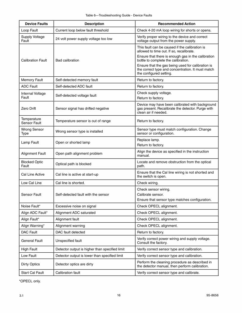
When the active fault has been identified, refer to the Troubleshooting Tables for a description of the fault and suggested corrective action.
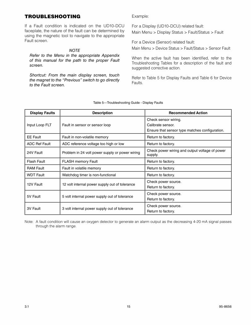
Refer to Table 5 for Display Faults and Table 6 for Device Faults.
Display Faults Description Recommended action
Input Loop FLT Fault in sensor or sensor loopCheck sensor wiring.Calibrate sensor.Ensure that sensor type matches configuration.
EE Fault Fault in non-volatile memory Return to factory.
ADC Ref Fault ADC reference voltage too high or low Return to factory.
24V Fault Problem in 24 volt power supply or power wiring Check power wiring and output voltage of power supply.
Flash Fault FLASH memory Fault Return to factory.
RAM Fault Fault in volatile memory Return to factory.
WDT Fault Watchdog timer is non-functional Return to factory.
12V Fault 12 volt internal power supply out of toleranceCheck power source. Return to factory.
5V Fault 5 volt internal power supply out of toleranceCheck power source. Return to factory.
3V Fault 3 volt internal power supply out of toleranceCheck power source. Return to factory.
Table 5—Troubleshooting Guide - Display Faults
Note: A fault condition will cause an oxygen detector to generate an alarm output as the decreasing 4-20 mA signal passes through the alarm range.
16 95-86563.1
Table 6—Troubleshooting Guide - Device Faults
Device Faults Description Recommended action
Loop Fault Current loop below fault threshold Check 4-20 mA loop wiring for shorts or opens.
Supply Voltage Fault 24 volt power supply voltage too low Verify proper wiring to the device and correct
voltage output from the power supply.
Calibration Fault Bad calibration
This fault can be caused if the calibration is allowed to time out. If so, recalibrate.Ensure that there is enough gas in the calibration bottle to complete the calibration.Ensure that the gas being used for calibration is the correct type and concentration. It must match the configured setting.
Memory Fault Self-detected memory fault Return to factory.
ADC Fault Self-detected ADC fault Return to factory.
Internal Voltage Fault Self-detected voltage fault
Check supply voltage.Return to factory.
Zero Drift Sensor signal has drifted negativeDevice may have been calibrated with background gas present. Recalibrate the detector. Purge with clean air if needed.
Temperature Sensor Fault Temperature sensor is out of range Return to factory.
Wrong Sensor Type Wrong sensor type is installed Sensor type must match configuration. Change
sensor or configuration.
Lamp Fault Open or shorted lampReplace lamp.Return to factory.
Alignment Fault Open path alignment problem Align the device as specified in the instruction manual.
Blocked Optic Fault Optical path is blocked Locate and remove obstruction from the optical
path.
Cal Line Active Cal line is active at start-up Ensure that the Cal line wiring is not shorted and the switch is open.
Low Cal Line Cal line is shorted. Check wiring.
Sensor Fault Self-detected fault with the sensorCheck sensor wiring.Calibrate sensor.Ensure that sensor type matches configuration.
Noise Fault* Excessive noise on signal Check OPECL alignment.
Align ADC Fault* Alignment ADC saturated Check OPECL alignment.
Align Fault* Alignment fault Check OPECL alignment.
Align Warning* Alignment warning Check OPECL alignment.
DAC Fault DAC fault detected Return to factory.
General Fault Unspecified fault Verify correct power wiring and supply voltage.Consult the factory.
High Fault Detector output is higher than specified limit Verify correct sensor type and calibration.
Low Fault Detector output is lower than specified limit Verify correct sensor type and calibration.
Dirty Optics Detector optics are dirty Perform the cleaning procedure as described in the detector manual, then perform calibration.
Start Cal Fault Calibration fault Verify correct sensor type and calibrate.
*OPECL only.
17 95-86563.1
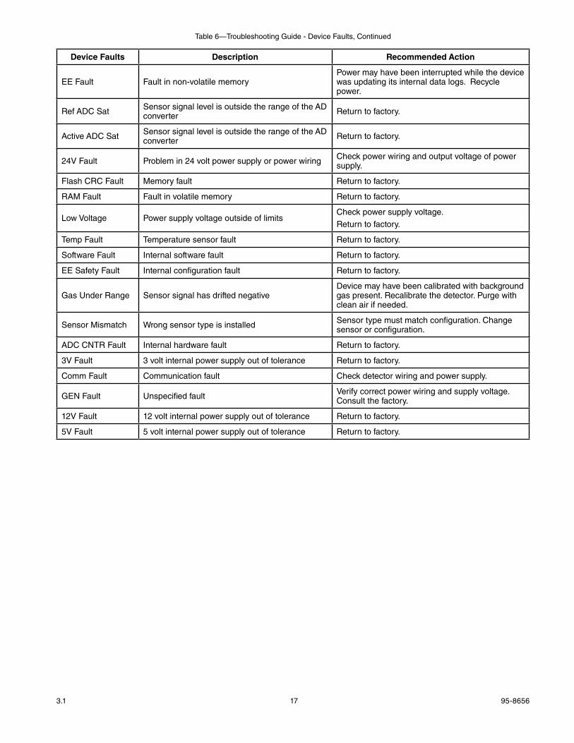
Device Faults Description Recommended action
EE Fault Fault in non-volatile memoryPower may have been interrupted while the device was updating its internal data logs. Recycle power.
Ref ADC Sat Sensor signal level is outside the range of the AD converter Return to factory.
Active ADC Sat Sensor signal level is outside the range of the AD converter Return to factory.
24V Fault Problem in 24 volt power supply or power wiring Check power wiring and output voltage of power supply.
Flash CRC Fault Memory fault Return to factory.
RAM Fault Fault in volatile memory Return to factory.
Low Voltage Power supply voltage outside of limitsCheck power supply voltage.Return to factory.
Temp Fault Temperature sensor fault Return to factory.
Software Fault Internal software fault Return to factory.
EE Safety Fault Internal configuration fault Return to factory.
Gas Under Range Sensor signal has drifted negativeDevice may have been calibrated with background gas present. Recalibrate the detector. Purge with clean air if needed.
Sensor Mismatch Wrong sensor type is installed Sensor type must match configuration. Change sensor or configuration.
ADC CNTR Fault Internal hardware fault Return to factory.
3V Fault 3 volt internal power supply out of tolerance Return to factory.
Comm Fault Communication fault Check detector wiring and power supply.
GEN Fault Unspecified fault Verify correct power wiring and supply voltage.Consult the factory.
12V Fault 12 volt internal power supply out of tolerance Return to factory.
5V Fault 5 volt internal power supply out of tolerance Return to factory.
Table 6—Troubleshooting Guide - Device Faults, Continued
18 95-86563.1
specificAtions
OPERATING VOLTAGE—24 Vdc nominal, operating range is 18 to 30 Vdc. Ripple cannot exceed 0.5 volt P-P.
OPERATING POWER—Heater off: 1.3 watts nominal @ 24 Vdc with
backlit display off. 2 watts @ 24 Vdc with backlit display on.Heater on: 4 watts additional.CGS model: Add 4 watts with CGS interface
board and CGS sensor installed.
Maximum power with heater and display on: 6 watts @ 30 Vdc (Standard model) 10 watts @ 30 Vdc (CGS model).
noTeHeater turns on when the internal temperature drops below –10°C (default operation).
LON COMMUNICATION —Digital communication, transformer isolated (78.5 kbps).
EQP/UD10 SySTEM ACCURACy—<1 ppm error.<1 %LFL error.With CGS sensor: ±3 %LFL, 0-50 range, ±5 %LFL 51-100 range.
EQP/UD10 SySTEM RESPONSE—Toxic gas: T90 < 10 sec.Combustible gas: T90 < 10 sec.With CGS sensor: T90 < 12 sec.
DETECTOR COMPATIBILITy—The UD10-DCU can be used with the Det-Tronics gas detectors listed in Table 7.
UNIT OF MEASUREMENT—PPM, % LFL, % V/V, LFLM, or Mg/M3.
OPERATING TEMPERATURE—–40°C to +75°C.
STORAGE TEMPERATURE—–55°C to +75°C.
HUMIDITy RANGE—5 to 95% RH (Det-Tronics verified).
ELECTRO-MAGNETIC COMPATIBILITy—EMC Directive 2004/108/ECEN55011 (Emissions)EN50270 (Immunity)
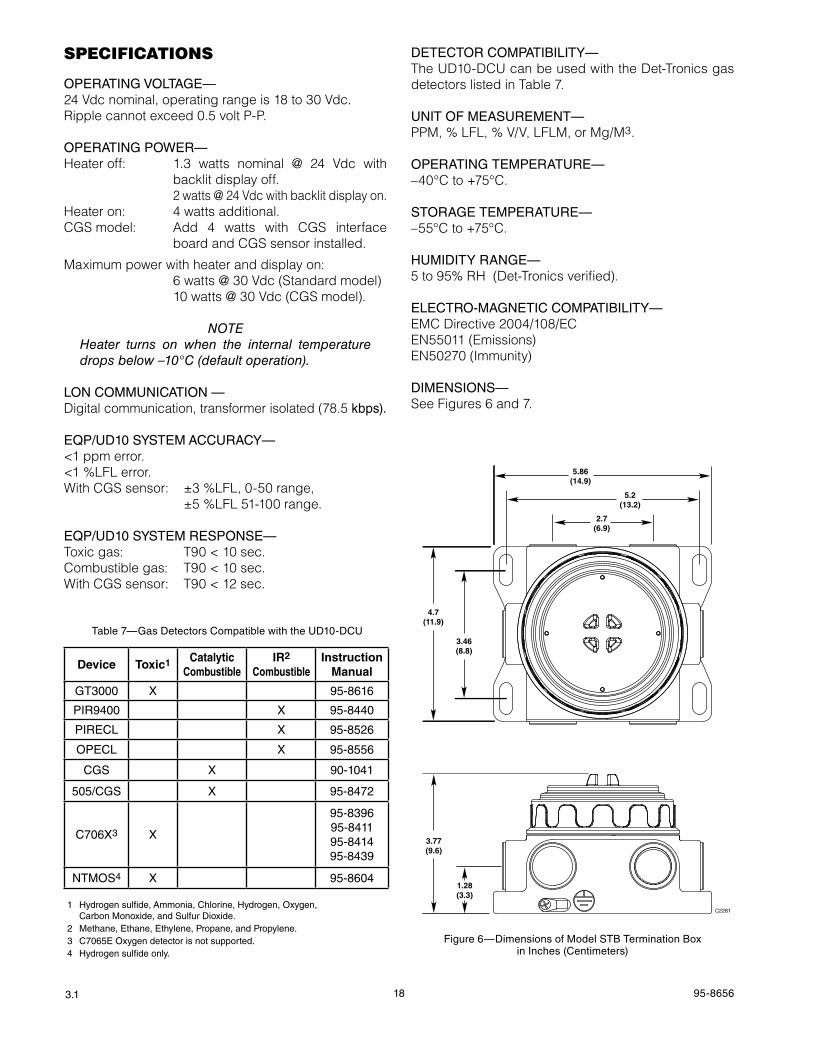
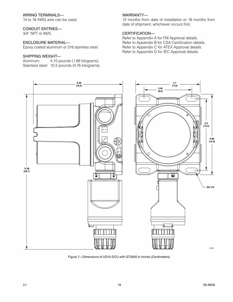
DIMENSIONS—See Figures 6 and 7.
Device Toxic1 Catalytic Combustible
IR2
CombustibleInstruction
manual
GT3000 X 95-8616
PIR9400 X 95-8440
PIRECL X 95-8526
OPECL X 95-8556
CGS X 90-1041
505/CGS X 95-8472
C706X3 X
95-8396 95-8411 95-8414 95-8439
NTMOS4 X 95-8604
1 Hydrogen sulfide, Ammonia, Chlorine, Hydrogen, Oxygen, Carbon Monoxide, and Sulfur Dioxide.2 Methane, Ethane, Ethylene, Propane, and Propylene.3 C7065E Oxygen detector is not supported.4 Hydrogen sulfide only.
Table 7—Gas Detectors Compatible with the UD10-DCU
Figure 6—Dimensions of Model STB Termination Box in Inches (Centimeters)
3.77(9.6)
1.28(3.3)
3.46(8.8)
4.7(11.9)
2.7(6.9)
5.2(13.2)
5.86(14.9)
C2281
19 95-86563.1
WIRING TERMINALS—14 to 18 AWG wire can be used.
CONDUIT ENTRIES—3/4” NPT or M25.
ENCLOSURE MATERIAL—Epoxy coated aluminum or 316 stainless steel.
SHIPPING WEIGHT—Aluminum: 4.15 pounds (1.88 kilograms).Stainless steel: 10.5 pounds (4.76 kilograms).
WARRANTy—12 months from date of installation or 18 months from date of shipment, whichever occurs first.
CERTIFICATION—Refer to Appendix A for FM Approval details.Refer to Appendix B for CSA Certification details.Refer to Appendix C for ATEx Approval details.Refer to Appendix D for IEC Approval details.
Figure 7—Dimensions of UD10-DCU with GT3000 in Inches (Centimeters)
11.28(28.7)
6.48(16.5)
3.46(8.8)
4.7(11.9)
5.2(13.2)
R0.175
5.86(14.9)
A2442
20 95-86563.1
DeVice repAir AnD return
Prior to returning devices, contact the nearest local Detector Electronics office so that a Return Material Identification (RMI) number can be assigned. a written statement describing the malfunction must accompany the returned device or component to assist and expedite finding the root cause of the failure.
Pack the unit properly. Always use sufficient packing material. Where applicable, use an antistatic bag as protection from electrostatic discharge. The RMI number should be clearly marked on the outside of the box.
noTeInadequate packaging that ultimately causes damage to the returned device during shipment will result in a service charge to repair the damage incurred during shipment.
Return all equipment transportation prepaid to the factory in Minneapolis.
noTeIt is highly recommended that a spare be kept on hand for field replacement to ensure continuous protection.
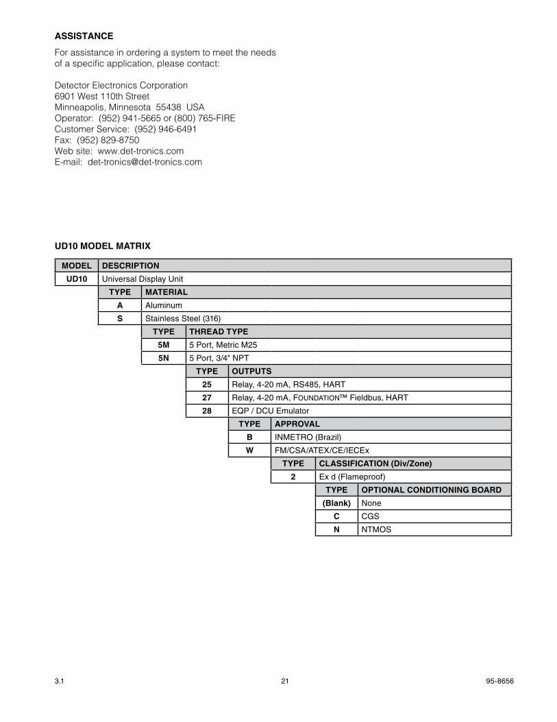
orDerinG informAtion
Sensor module, transmitter module and termination boxes (if used) must be ordered separately.
Refer to the UD10-DCU Model Matrix for ordering details.
REPLaCEmENT PaRTS
Part Number Description
009700-001 Magnetic Tool010535-001 Electronics Module, DCU101197-001* Stop Plug, 3/4" NPT, AL101197-004* Stop Plug, 3/4" NPT, SS103517-001 Stop Plug, M25, AL, IP66101197-003 Stop Plug, M25, SS, IP66010816-001 Stop Plug, 20PK, 3/4" NPT, AL 010817-001 Stop Plug, 20PK, 3/4" NPT, SS010818-001 Stop Plug, 20PK, M25, AL, IP66, ExDE010819-001 Stop Plug, 20PK, M25, SS, IP66, ExDE102804-001 Reducer, M25 to M20, AL102804-003 Reducer, M25 to M20, SS102868-001 Lubriplate grease, 14 oz.005003-001 Lubriplate grease, 1 oz.
*NEMA 4/IP66 rating requires addition of non-hardening thread sealant or Teflon tape.
21 95-86563.1
aSSISTaNCE
For assistance in ordering a system to meet the needs of a specific application, please contact:
Detector Electronics Corporation6901 West 110th StreetMinneapolis, Minnesota 55438 USAOperator: (952) 941-5665 or (800) 765-FIRECustomer Service: (952) 946-6491Fax: (952) 829-8750Web site: www.det-tronics.comE-mail: [email protected]
mODEL DESCRIPTION
UD10 Universal Display Unit
TYPE maTERIaL
a Aluminum
S Stainless Steel (316)
TYPE ThREaD TYPE
5m 5 Port, Metric M25
5N 5 Port, 3/4" NPT
TYPE OUTPUTS
25 Relay, 4-20 mA, RS485, HART
27 Relay, 4-20 mA, Foundation™ Fieldbus, HART
28 EQP / DCU Emulator
TYPE aPPROvaL
b INMETRO (Brazil)
w FM/CSA/ATEX/CE/IECEx
TYPE CLaSSIFICaTION (Div/Zone)
2 Ex d (Flameproof)
TYPE OPTIONaL CONDITIONINg bOaRD
(blank) None
C CGS
N NTMOS
UD10 mODEL maTRIx
95-86563.1 A-1
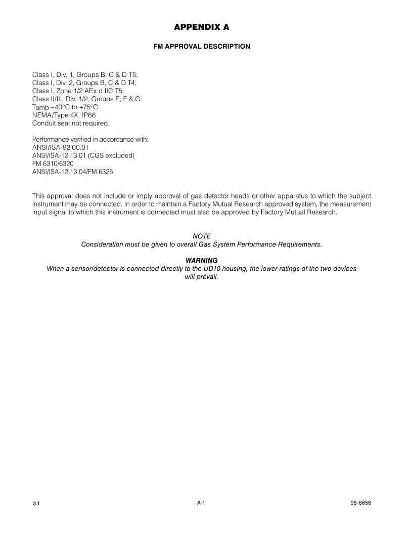
AppenDix A
Fm aPPROvaL DESCRIPTION
Class I, Div. 1, Groups B, C & D T5;Class I, Div. 2, Groups B, C & D T4;Class I, Zone 1/2 AEx d IIC T5;Class II/III, Div. 1/2, Groups E, F & G.Tamb –40°C to +75°CNEMA/Type 4x, IP66Conduit seal not required.
Performance verified in accordance with:ANSI/ISA-92.00.01ANSI/ISA-12.13.01 (CGS excluded)FM 6310/6320ANSI/ISA-12.13.04/FM 6325
This approval does not include or imply approval of gas detector heads or other apparatus to which the subject instrument may be connected. In order to maintain a Factory Mutual Research approved system, the measurement input signal to which this instrument is connected must also be approved by Factory Mutual Research.
noTeConsideration must be given to overall Gas System Performance Requirements.
WarnIngWhen a sensor/detector is connected directly to the UD10 housing, the lower ratings of the two devices
will prevail.
95-86563.1 B-1
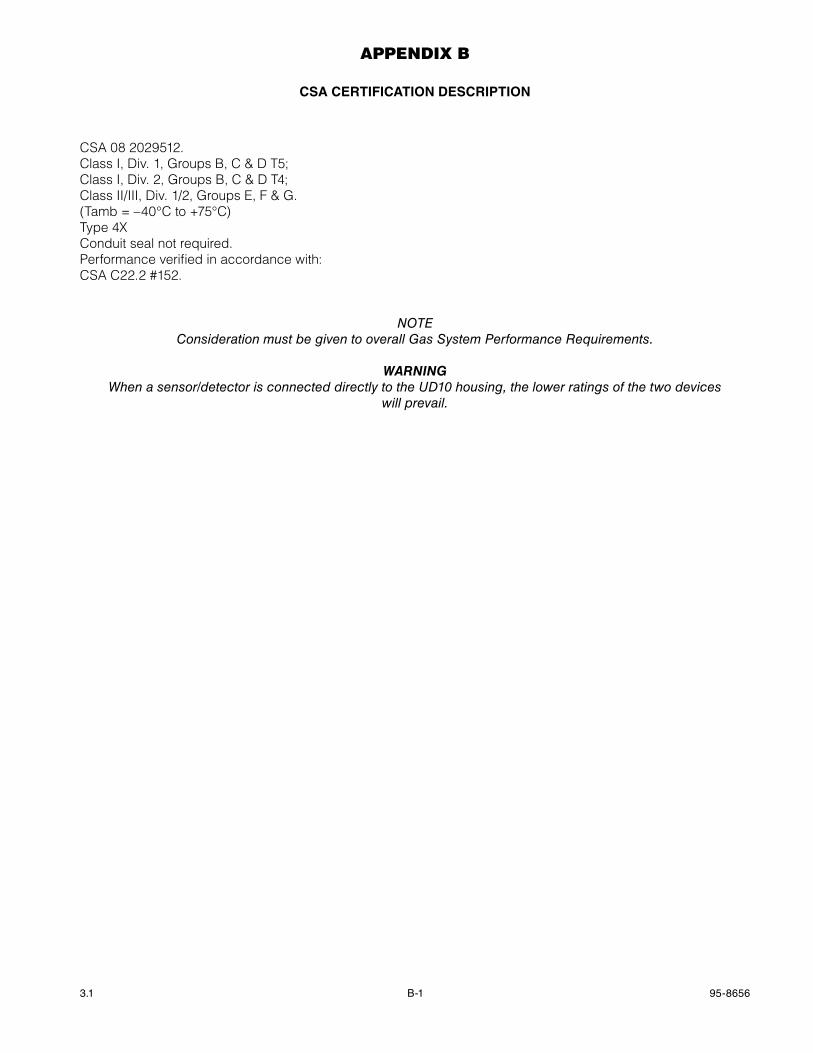
AppenDix b
CSa CERTIFICaTION DESCRIPTION
CSA 08 2029512.Class I, Div. 1, Groups B, C & D T5;Class I, Div. 2, Groups B, C & D T4;Class II/III, Div. 1/2, Groups E, F & G.(Tamb = –40°C to +75°C)Type 4xConduit seal not required.Performance verified in accordance with:CSA C22.2 #152.
noTeConsideration must be given to overall Gas System Performance Requirements.
WarnIngWhen a sensor/detector is connected directly to the UD10 housing, the lower ratings of the two devices
will prevail.
95-86563.1 C-1
AppenDix c
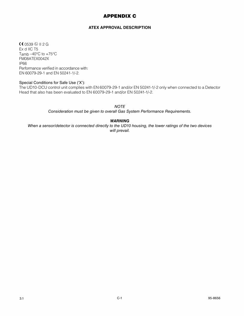
aTEx aPPROvaL DESCRIPTION
0539 FM�APPROVED II 2 G
Ex d IIC T5Tamb –40°C to +75°CFM08ATEx0042xIP66Performance verified in accordance with:EN 60079-29-1 and EN 50241-1/-2.
Special Conditions for Safe Use (‘X’):The UD10-DCU control unit complies with EN 60079-29-1 and/or EN 50241-1/-2 only when connected to a Detector Head that also has been evaluated to EN 60079-29-1 and/or EN 50241-1/-2.
noTeConsideration must be given to overall Gas System Performance Requirements.
WarnIngWhen a sensor/detector is connected directly to the UD10 housing, the lower ratings of the two devices
will prevail.
95-86563.1 D-1
AppenDix D
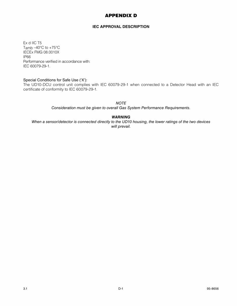
IEC aPPROvaL DESCRIPTION
Ex d IIC T5Tamb –40°C to +75°CIECEx FMG 08.0010xIP66Performance verified in accordance with:IEC 60079-29-1.
Special Conditions for Safe Use (‘X’):The UD10-DCU control unit complies with IEC 60079-29-1 when connected to a Detector Head with an IEC certificate of conformity to IEC 60079-29-1.
noTeConsideration must be given to overall Gas System Performance Requirements.
WarnIngWhen a sensor/detector is connected directly to the UD10 housing, the lower ratings of the two devices
will prevail.
E-1 95-86563.1
AppenDix e
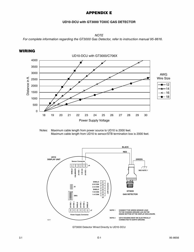
UD10-DCU with gT3000 TOxIC gaS DETECTOR
noTeFor complete information regarding the GT3000 Gas Detector, refer to instruction manual 95-8616.
WirinG
4000
3500
3000
2500
2000
1500
1000
500
018 19 20 21 22 23 24 25 26 27 28 29 30
Power Supply Voltage
Dis
tanc
e in
ft.
UD10-DCU with GT3000/C706X
12141618
AWGWire Size
Notes: Maximum cable length from power source to UD10 is 2000 feet. Maximum cable length from UD10 to sensor/STB termination box is 2000 feet.
GT3000
GAS DETECTOR
BLACK
RED
GREEN
SEE NOTE 1
NOTE 1 CONNECT THE GREEN SENSOR LEAD TO THE CHASSIS GROUND LUG ON THE INSIDE BOTTOM OF THE DISPLAY ENCLOSURE.
NOTE 2 UD10 HOUSING MUST BE ELECTRICALLY CONNECTED TO EARTH GROUND.A2511
Sensor Connector
Power Supply Connector
LON
Co
nn
ecto
r
J4
J3
J7
24 V
DC
–
24 V
DC
+
SH
IEL
D
24 V
DC
–
24 V
DC
+
SH
IEL
D
SH
IEL
D
CA
LIB
RA
TE
24 V
DC
–
4-20
mA
24 V
DC
+
J4-1
J4-2
J4-3
J4-4
J4-5
J7-6
J7-5
J7-4
J7-3
J7-2
J7-1
SHIELD
2 B COM
2 A COM
SHIELD
1 B COM
1 A COM
J3-1
J3-2
J3-3
J3-4
J3-5
J3-6
UD10 DISPLAY UNIT
SW3
J2
ON
GT3000 Detector Wired Directly to UD10-DCU
E-2 95-86563.1
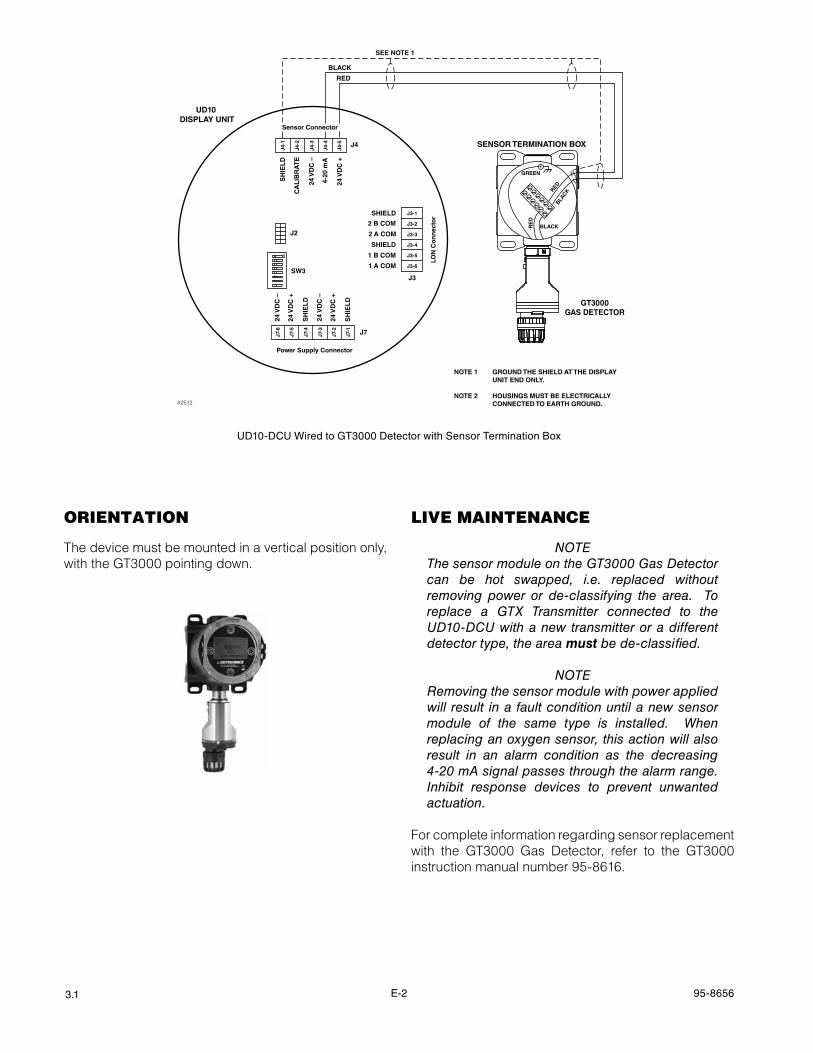
UD10-DCU Wired to GT3000 Detector with Sensor Termination Box
NOTE 1 GROUND THE SHIELD AT THE DISPLAY UNIT END ONLY.
NOTE 2 HOUSINGS MUST BE ELECTRICALLY CONNECTED TO EARTH GROUND.
SEE NOTE 1
A2512
RED
BLACK
GT3000GAS DETECTOR
SENSOR TERMINATION BOX
RED
RE
D
BLACK
BLACK
GREEN
Sensor Connector
Power Supply Connector
LON
Co
nn
ecto
r
J4
J3
J7
24 V
DC
–
24 V
DC
+
SH
IEL
D
24 V
DC
–
24 V
DC
+
SH
IEL
D
SH
IEL
D
CA
LIB
RA
TE
24 V
DC
–
4-20
mA
24 V
DC
+
J4-1
J4-2
J4-3
J4-4
J4-5
J7-6
J7-5
J7-4
J7-3
J7-2
J7-1
SHIELD
2 B COM
2 A COM
SHIELD
1 B COM
1 A COM
J3-1
J3-2
J3-3
J3-4
J3-5
J3-6
UD10 DISPLAY UNIT
SW3
J2
ON
orientAtion
The device must be mounted in a vertical position only, with the GT3000 pointing down.
liVe mAintenAnce
noTeThe sensor module on the GT3000 Gas Detector can be hot swapped, i.e. replaced without removing power or de-classifying the area. To replace a GTX Transmitter connected to the UD10-DCU with a new transmitter or a different detector type, the area must be de-classified.
noTeRemoving the sensor module with power applied will result in a fault condition until a new sensor module of the same type is installed. When replacing an oxygen sensor, this action will also result in an alarm condition as the decreasing 4-20 mA signal passes through the alarm range. Inhibit response devices to prevent unwanted actuation.
For complete information regarding sensor replacement with the GT3000 Gas Detector, refer to the GT3000 instruction manual number 95-8616.
E-3 95-86563.1
cAlibrAtion
gT3000 wITh TOxIC gaS SENSOR
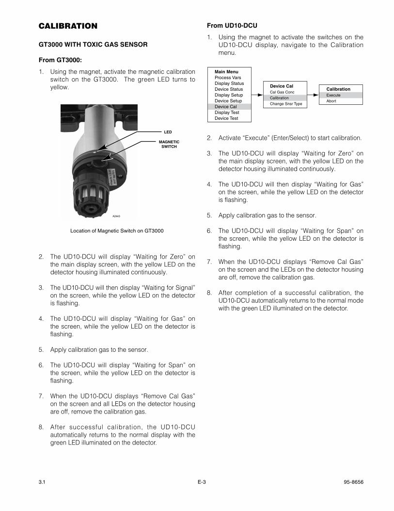
From gT3000:
1. Using the magnet, activate the magnetic calibration switch on the GT3000. The green LED turns to yellow.
MAGNETICSWITCH
LED
A2443
Location of Magnetic Switch on GT3000
2. The UD10-DCU will display “Waiting for Zero” on the main display screen, with the yellow LED on the detector housing illuminated continuously.
3. The UD10-DCU will then display “Waiting for Signal” on the screen, while the yellow LED on the detector is flashing.
4. The UD10-DCU will display “Waiting for Gas” on the screen, while the yellow LED on the detector is flashing.
5. Apply calibration gas to the sensor.
6. The UD10-DCU will display “Waiting for Span” on the screen, while the yellow LED on the detector is flashing.
7. When the UD10-DCU displays “Remove Cal Gas” on the screen and all LEDs on the detector housing are off, remove the calibration gas.
8. After successful calibration, the UD10-DCU automatically returns to the normal display with the green LED illuminated on the detector.
From UD10-DCU
1. Using the magnet to activate the switches on the UD10-DCU display, navigate to the Calibration menu.
Main MenuProcess VarsDisplay StatusDevice StatusDisplay SetupDevice SetupDevice CalDisplay TestDevice Test
Device CalCal Gas Conc
Calibration
Change Snsr Type
CalibrationExecute
Abort
2. Activate “Execute” (Enter/Select) to start calibration.
3. The UD10-DCU will display “Waiting for Zero” on the main display screen, with the yellow LED on the detector housing illuminated continuously.
4. The UD10-DCU will then display “Waiting for Gas” on the screen, while the yellow LED on the detector is flashing.
5. Apply calibration gas to the sensor.
6. The UD10-DCU will display “Waiting for Span” on the screen, while the yellow LED on the detector is flashing.
7. When the UD10-DCU displays “Remove Cal Gas” on the screen and the LEDs on the detector housing are off, remove the calibration gas.
8. After completion of a successful calibration, the UD10-DCU automatically returns to the normal mode with the green LED illuminated on the detector.
E-4 95-86563.1
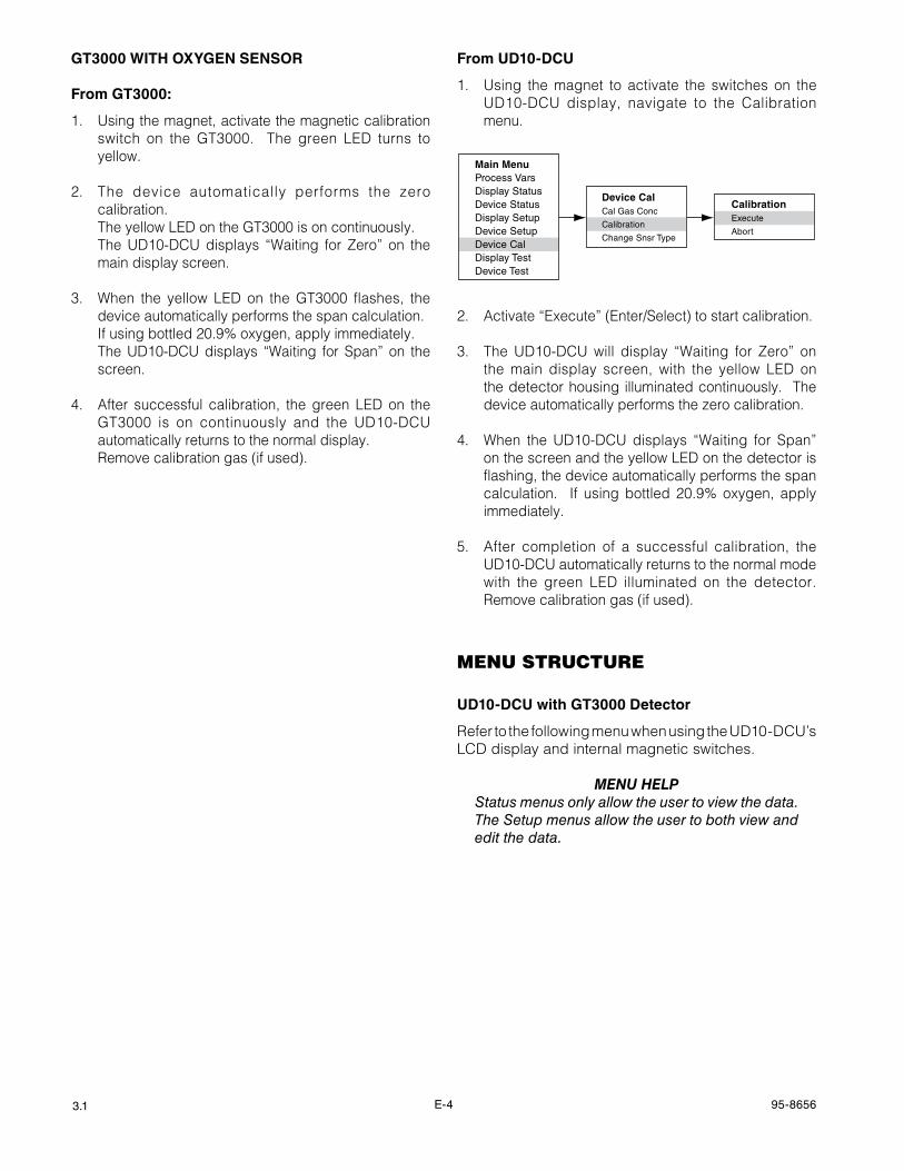
gT3000 wITh OxYgEN SENSOR
From gT3000:
1. Using the magnet, activate the magnetic calibration switch on the GT3000. The green LED turns to yellow.
2. The device automatically performs the zero calibration.
The yellow LED on the GT3000 is on continuously. The UD10-DCU displays “Waiting for Zero” on the
main display screen.
3. When the yellow LED on the GT3000 flashes, the device automatically performs the span calculation.
If using bottled 20.9% oxygen, apply immediately. The UD10-DCU displays “Waiting for Span” on the
screen.
4. After successful calibration, the green LED on the GT3000 is on continuously and the UD10-DCU automatically returns to the normal display.
Remove calibration gas (if used).
From UD10-DCU
1. Using the magnet to activate the switches on the UD10-DCU display, navigate to the Calibration menu.
Main MenuProcess VarsDisplay StatusDevice StatusDisplay SetupDevice SetupDevice CalDisplay TestDevice Test
Device CalCal Gas Conc
Calibration
Change Snsr Type
CalibrationExecute
Abort
2. Activate “Execute” (Enter/Select) to start calibration.
3. The UD10-DCU will display “Waiting for Zero” on the main display screen, with the yellow LED on the detector housing illuminated continuously. The device automatically performs the zero calibration.
4. When the UD10-DCU displays “Waiting for Span” on the screen and the yellow LED on the detector is flashing, the device automatically performs the span calculation. If using bottled 20.9% oxygen, apply immediately.
5. After completion of a successful calibration, the UD10-DCU automatically returns to the normal mode with the green LED illuminated on the detector. Remove calibration gas (if used).
menu structure
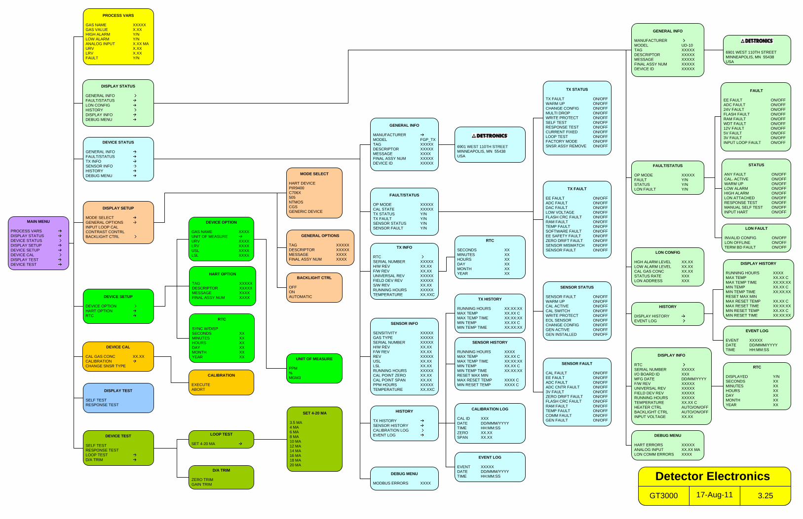
UD10-DCU with gT3000 Detector
Refer to the following menu when using the UD10-DCU’s LCD display and internal magnetic switches.
menu HeLpStatus menus only allow the user to view the data. The Setup menus allow the user to both view and edit the data.
MAIN MENU
PROCESS VARSDISPLAY STATUSDEVICE STATUSDISPLAY SETUPDEVICE SETUPDEVICE CALDISPLAY TESTDEVICE TEST
PROCESS VARS
GAS NAME XXXXXGAS VALUE X.XXHIGH ALARM Y/NLOW ALARM Y/NANALOG INPUT X.XX MAURV X.XXLRV X.XXFAULT Y/N
DISPLAY STATUS
GENERAL INFOFAULT/STATUSLON CONFIGHISTORYDISPLAY INFODEBUG MENU
DISPLAY SETUP
MODE SELECTGENERAL OPTIONSINPUT LOOP CALCONTRAST CONTRLBACKLIGHT CTRL
DISPLAY TEST
SELF TESTRESPONSE TEST
FAULT/STATUS
OP MODE XXXXXFAULT Y/NSTATUS Y/NLON FAULT Y/N
GENERAL INFO
MANUFACTURERMODEL UD-10TAG XXXXXDESCRIPTOR XXXXXMESSAGE XXXXXFINAL ASSY NUM XXXXXDEVICE ID XXXXX
HISTORY
DISPLAY HISTORYEVENT LOG
DISPLAY INFO
RTCSERIAL NUMBER XXXXXI/O BOARD ID XXXMFG DATE DD/MM/YYYYF/W REV XXXXXUNIVERSAL REV XXXXXFIELD DEV REV XXXXXRUNNING HOURS XXXXXTEMPERATURE XX.XX CHEATER CTRL AUTO/ON/OFFBACKLIGHT CTRL AUTO/ON/OFFINPUT VOLTAGE XX.XX
STATUS
ANY FAULT ON/OFFCAL. ACTIVE ON/OFFWARM UP ON/OFFLOW ALARM ON/OFFHIGH ALARM ON/OFFLON ATTACHED ON/OFFRESPONSE TEST ON/OFFMANUAL SELF TEST ON/OFFINPUT HART ON/OFF
EVENT LOG
EVENT XXXXXDATE DD/MMM/YYYYTIME HH:MM:SS
RTC
DISPLAYED Y/NSECONDS XXMINUTES XXHOURS XXDAY XXMONTH XXYEAR XX
MODE SELECT
HART DEVICEPIR9400C706X505NTMOSCGSGENERIC DEVICE
D/A TRIM
ZERO TRIMGAIN TRIM
DEVICE TEST
SELF TESTRESPONSE TESTLOOP TESTD/A TRIM
LOOP TEST
SET 4-20 MA
DEVICE CAL
CAL GAS CONC XX.XXCALIBRATIONCHANGE SNSR TYPE
CALIBRATION
EXECUTEABORT
DEVICE SETUP
DEVICE OPTIONHART OPTIONRTC
DEVICE STATUS
GENERAL INFOFAULT/STATUSTX INFOSENSOR INFOHISTORYDEBUG MENU
HISTORY
TX HISTORYSENSOR HISTORYCALIBRATION LOGEVENT LOG
GENERAL INFO
MANUFACTURERMODEL FGP_TXTAG XXXXXDESCRIPTOR XXXXXMESSAGE XXXXFINAL ASSY NUM XXXXXDEVICE ID XXXXX
FAULT/STATUS
OP MODE XXXXXCAL STATE XXXXXTX STATUS Y/NTX FAULT Y/NSENSOR STATUS Y/NSENSOR FAULT Y/N
TX INFO
RTCSERIAL NUMBER XXXXXH/W REV XX.XXF/W REV XX.XXUNIVERSAL REV XXXXXFIELD DEV REV XXXXXS/W REV XX.XXRUNNING HOURS XXXXXTEMPERATURE XX.XXC
SENSOR INFO
SENSITIVITY XXXXXGAS TYPE XXXXXSERIAL NUMBER XXXXXH/W REV XX.XXF/W REV XX.XXREV XXXXXUSL XX.XXLSL XX.XXRUNNING HOURS XXXXXCAL POINT ZERO XX.XXCAL POINT SPAN XX.XXPPM HOURS XXXXXTEMPERATURE XX.XXC
EVENT LOG
EVENT XXXXXDATE DD/MMM/YYYYTIME HH:MM:SS
CALIBRATION LOG
CAL ID XXXDATE DD/MMM/YYYYTIME HH:MM:SSZERO XX.XXSPAN XX.XX
RTC
SECONDS XXMINUTES XXHOURS XXDAY XXMONTH XXYEAR XX
DEBUG MENU
HART ERRORS XXXXXANALOG INPUT XX.XX MALON COMM ERRORS XXXX
SET 4-20 MA
3.5 MA4 MA6 MA8 MA10 MA12 MA14 MA16 MA18 MA20 MA
6901 WEST 110TH STREETMINNEAPOLIS, MN 55438USA
TX HISTORY
RUNNING HOURS XX:XX:XXMAX TEMP XX.XX CMAX TEMP TIME XX:XX:XXMIN TEMP XX.XX CMIN TEMP TIME XX:XX:XX
DISPLAY HISTORY
RUNNING HOURS XXXXMAX TEMP XX.XX CMAX TEMP TIME XX:XX:XXMIN TEMP XX.XX CMIN TEMP TIME XX:XX:XXRESET MAX MINMAX RESET TEMP XX.XX CMAX RESET TIME XX:XX:XXMIN RESET TEMP XX.XX CMIN RESET TIME XX:XX:XX
TX STATUS
TX FAULT ON/OFFWARM UP ON/OFFCHANGE CONFIG ON/OFFMULTI DROP ON/OFFWRITE PROTECT ON/OFFSELF TEST ON/OFFRESPONSE TEST ON/OFFCURRENT FIXED ON/OFFLOOP TEST ON/OFFFACTORY MODE ON/OFFSNSR ASSY REMOVE ON/OFF
TX FAULT
EE FAULT ON/OFFADC FAULT ON/OFFDAC FAULT ON/OFFLOW VOLTAGE ON/OFFFLASH CRC FAULT ON/OFFRAM FAULT ON/OFFTEMP FAULT ON/OFFSOFTWARE FAULT ON/OFFEE SAFETY FAULT ON/OFFZERO DRIFT FAULT ON/OFFSENSOR MISMATCH ON/OFFSENSOR FAULT ON/OFF
SENSOR STATUS
SENSOR FAULT ON/OFFWARM UP ON/OFFCAL ACTIVE ON/OFFCAL SWITCH ON/OFFWRITE PROTECT ON/OFFEOL SENSOR ON/OFFCHANGE CONFIG ON/OFFGEN ACTIVE ON/OFFGEN INSTALLED ON/OFF
SENSOR FAULT
CAL FAULT ON/OFFEE FAULT ON/OFFADC FAULT ON/OFFADC CNTR FAULT ON/OFF3V FAULT ON/OFFZERO DRIFT FAULT ON/OFFFLASH CRC FAULT ON/OFFRAM FAULT ON/OFFTEMP FAULT ON/OFFCOMM FAULT ON/OFFGEN FAULT ON/OFF
DEBUG MENU
MODBUS ERRORS XXXX
SENSOR HISTORY
RUNNING HOURS XXXXMAX TEMP XX.XX CMAX TEMP TIME XX:XX:XXMIN TEMP XX.XX CMIN TEMP TIME XX:XX:XXRESET MAX MINMAX RESET TEMP XXXX CMIN RESET TEMP XXXX C
FAULT
EE FAULT ON/OFFADC FAULT ON/OFF24V FAULT ON/OFFFLASH FAULT ON/OFFRAM FAULT ON/OFFWDT FAULT ON/OFF12V FAULT ON/OFF5V FAULT ON/OFF3V FAULT ON/OFFINPUT LOOP FAULT ON/OFF
LON CONFIG
HGH ALARM LEVEL XX.XXLOW ALARM LEVEL XX.XXCAL GAS CONC XX.XXSTATUS RATE XXXLON ADDRESS XXX
6901 WEST 110TH STREETMINNEAPOLIS, MN 55438USA
GENERAL OPTIONS
TAG XXXXXDESCRIPTOR XXXXXMESSAGE XXXXFINAL ASSY NUM XXXX
LON FAULT
INVALID CONFIG ON/OFFLON OFFLINE ON/OFFTERM BD FAULT ON/OFF
BACKLIGHT CTRL
OFFONAUTOMATIC
HART OPTION
TAG XXXXXDESCRIPTOR XXXXXMESSAGE XXXXFINAL ASSY NUM XXXX
DEVICE OPTION
GAS NAME XXXXUNIT OF MEASUREURV XXXXLRV XXXXUSL XXXXLSL XXXX
RTC
SYNC W/DISPSECONDS XXMINUTES XXHOURS XXDAY XXMONTH XXYEAR XX UNIT OF MEASURE
PPM%MGM3
17-Aug-11GT3000 3.25
Detector Electronics
F-1 95-86563.1
AppenDix f
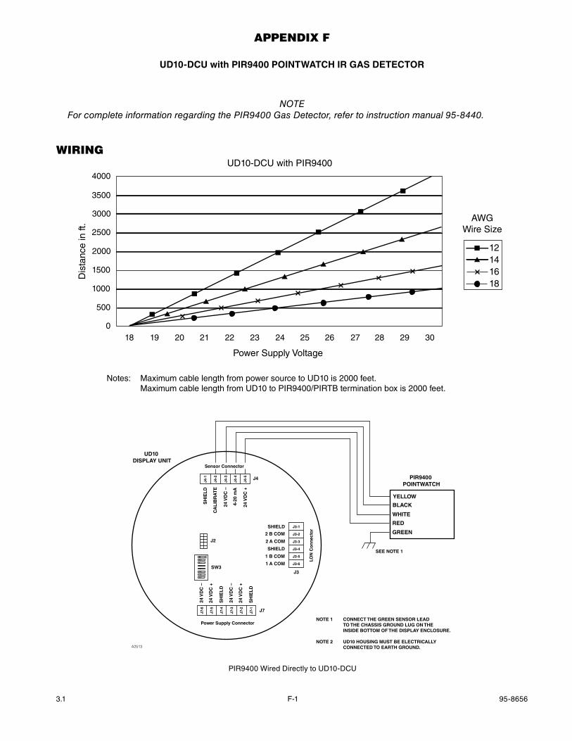
UD10-DCU with PIR9400 POINTwaTCh IR gaS DETECTOR
noTeFor complete information regarding the PIR9400 Gas Detector, refer to instruction manual 95-8440.
WirinG
4000
3500
3000
2500
2000
1500
1000
500
018 19 20 21 22 23 24 25 26 27 28 29 30
Power Supply Voltage
Dis
tanc
e in
ft.
UD10-DCU with PIR9400
12141618
AWGWire Size
Notes: Maximum cable length from power source to UD10 is 2000 feet. Maximum cable length from UD10 to PIR9400/PIRTB termination box is 2000 feet.
PIR9400 POINTWATCH
BLACK
RED
YELLOW
WHITE
GREEN
SEE NOTE 1
NOTE 1 CONNECT THE GREEN SENSOR LEAD TO THE CHASSIS GROUND LUG ON THE INSIDE BOTTOM OF THE DISPLAY ENCLOSURE.
NOTE 2 UD10 HOUSING MUST BE ELECTRICALLY CONNECTED TO EARTH GROUND.A2513
Sensor Connector
Power Supply Connector
LON
Co
nn
ecto
r
J4
J3
J7
24 V
DC
–
24 V
DC
+
SH
IEL
D
24 V
DC
–
24 V
DC
+
SH
IEL
D
SH
IEL
D
CA
LIB
RA
TE
24 V
DC
–
4-20
mA
24 V
DC
+
J4-1
J4-2
J4-3
J4-4
J4-5
J7-6
J7-5
J7-4
J7-3
J7-2
J7-1
SHIELD
2 B COM
2 A COM
SHIELD
1 B COM
1 A COM
J3-1
J3-2
J3-3
J3-4
J3-5
J3-6
UD10 DISPLAY UNIT
SW3
J2
ON
PIR9400 Wired Directly to UD10-DCU

F-2 95-86563.1
instAllAtion notes
ImportantHydrocarbon-based grease emits hydrocarbon vapors that will be measured by PointWatch, resulting in inaccurate gas level readings. use only low vapor pressure Lubriplate grease or teflon tape on the pointWatch detector and associated termination box. Do not get grease on the optics of the detector. A suitable grease is listed in the “ordering Information” section in this manual.
ImportantIn applications where both PointWatch and catalytic type sensors are used, ensure that the grease used to lubricate the PointWatch detector threads does not come into contact with the catalytic sensors, since poisoning of the catalytic sensors could result. It is strongly recommended that maintenance personnel wash their hands between handling the two types of sensors.
orientAtion
It is highly recommended that the PIR9400 be installed in the horizontal position. The detector is not position-sensitive in terms of its ability to detect gas. However, the weather baffle assembly provides superior performance when installed in a horizontal position. (See illustration below).
SEE NOTE 1
NOTE 1 CONNECT THE GREEN SENSOR LEAD TO THE CHASSIS GROUND LUG ON THE INSIDE BOTTOM OF THE PIRTB.
NOTE 2 HOUSINGS MUST BE ELECTRICALLY CONNECTED TO EARTH GROUND.A2557
PIRTB JUNCTION BOXPIR9400
DETECTOR
YELLOWWHITEBLACKRED
SPARE
CAL
4 – 20
RET
+24 +24
RET
4 – 20
CAL
GREEN
CHASSIS
Sensor Connector
Power Supply Connector
LON
Co
nn
ecto
r
J4
J3
J7
24 V
DC
–
24 V
DC
+
SH
IEL
D
24 V
DC
–
24 V
DC
+
SH
IEL
D
SH
IEL
D
CA
LIB
RA
TE
24 V
DC
–
4-20
mA
24 V
DC
+
J4-1
J4-2
J4-3
J4-4
J4-5
J7-6
J7-5
J7-4
J7-3
J7-2
J7-1
SHIELD
2 B COM
2 A COM
SHIELD
1 B COM
1 A COM
J3-1
J3-2
J3-3
J3-4
J3-5
J3-6
UD10 DISPLAY UNIT
SW3
J2
ON
UD10-DCU Wired to PIR9400 with PIRTB Termination Box
F-3 95-86563.1
chAnGinG operAtinG moDes
When used with a PIR9400, the operating mode of the UD10-DCU must be changed from “HART Device” to “PIR9400” mode. Refer to the “Startup” section of this manual for details.
cAlibrAtion
To initiate calibration of the PIR9400 from the UD10-DCU Display:
1. Using the magnet to activate the switches on the UD10-DCU display, navigate to the “Calibration” menu.
Main MenuProcess VarsDisplay StatusDevice StatusDisplay SetupDevice SetupDevice CalDisplay Test
Device CalCalibration
Cal Gas Conc
CalibrationExecute
Abort
2. Activate “Execute” (Enter/Select) to start calibration.
3. The UD10-DCU will display “Waiting for Zero” on the main display screen.
4. The UD10-DCU will then display “Waiting for Gas” on the screen.
5. Apply calibration gas to the PIR9400.
6. The UD10-DCU will continue to display “Waiting for Gas” on the screen.
7. When the UD10-DCU displays “Remove Cal Gas” on the screen, remove the calibration gas from the PIR9400.
8. The UD10-DCU automatically returns to the normal mode after successful calibration.
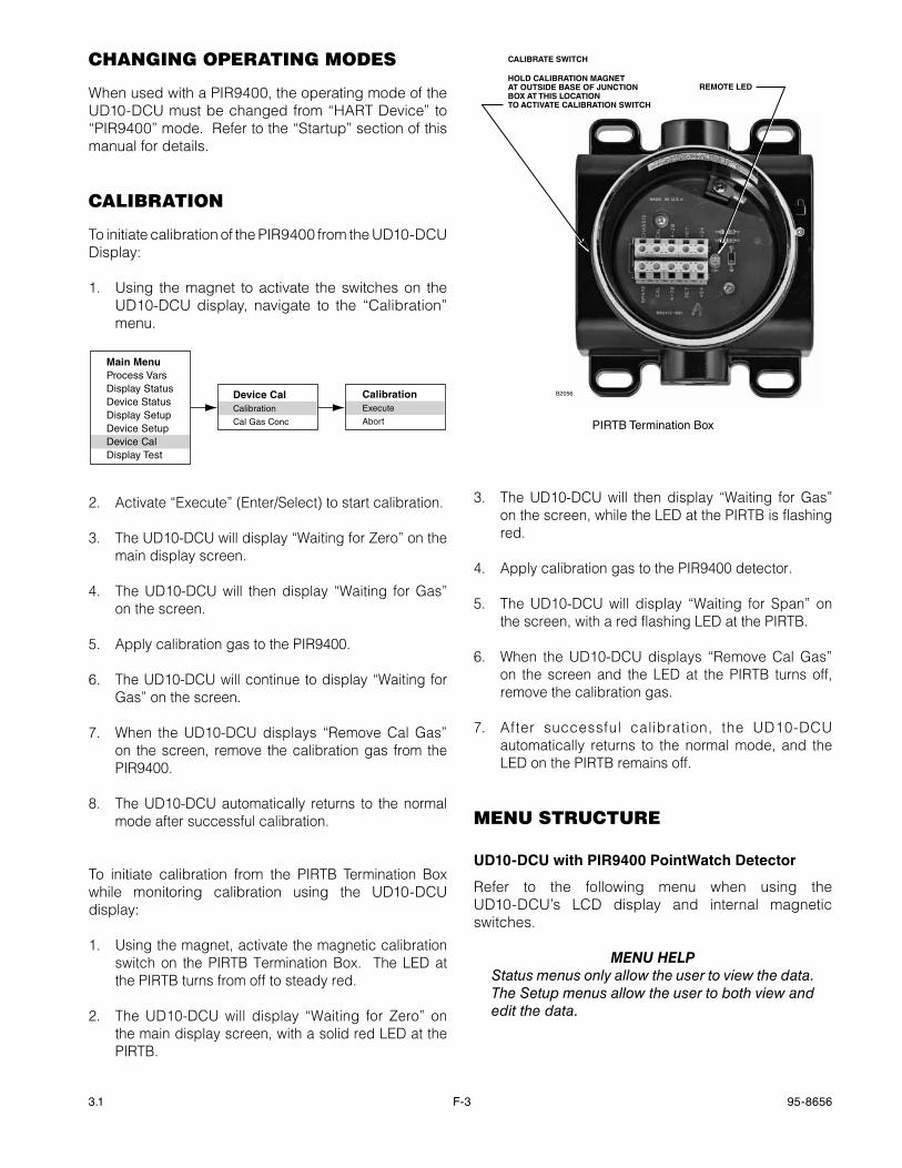
To initiate calibration from the PIRTB Termination Box while monitoring calibration using the UD10-DCU display:
1. Using the magnet, activate the magnetic calibration switch on the PIRTB Termination Box. The LED at the PIRTB turns from off to steady red.
2. The UD10-DCU will display “Waiting for Zero” on the main display screen, with a solid red LED at the PIRTB.
3. The UD10-DCU will then display “Waiting for Gas” on the screen, while the LED at the PIRTB is flashing red.
4. Apply calibration gas to the PIR9400 detector.
5. The UD10-DCU will display “Waiting for Span” on the screen, with a red flashing LED at the PIRTB.
6. When the UD10-DCU displays “Remove Cal Gas” on the screen and the LED at the PIRTB turns off, remove the calibration gas.
7. After successful calibration, the UD10-DCU automatically returns to the normal mode, and the LED on the PIRTB remains off.
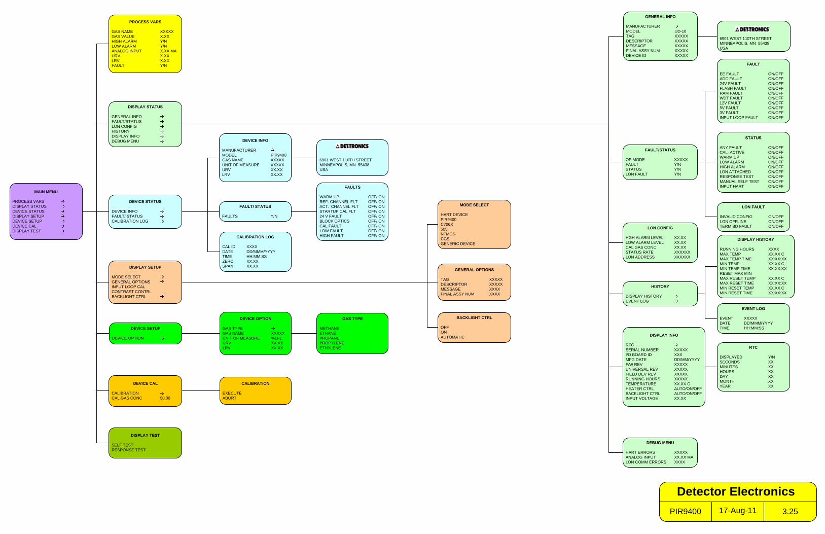
menu structure
UD10-DCU with PIR9400 Pointwatch Detector
Refer to the following menu when using the UD10-DCU’s LCD display and internal magnetic switches.
menu HeLpStatus menus only allow the user to view the data. The Setup menus allow the user to both view and edit the data.
CALIBRATE SWITCH
B2056
HOLD CALIBRATION MAGNETAT OUTSIDE BASE OF JUNCTION BOX AT THIS LOCATIONTO ACTIVATE CALIBRATION SWITCH
REMOTE LED
PIRTB Termination Box
MAIN MENU
PROCESS VARSDISPLAY STATUSDEVICE STATUSDISPLAY SETUPDEVICE SETUPDEVICE CALDISPLAY TEST
PROCESS VARS
GAS NAME XXXXXGAS VALUE X.XXHIGH ALARM Y/NLOW ALARM Y/NANALOG INPUT X.XX MAURV X.XXLRV X.XXFAULT Y/N
DISPLAY SETUP
MODE SELECTGENERAL OPTIONSINPUT LOOP CALCONTRAST CONTRLBACKLIGHT CTRL
DISPLAY TEST
SELF TESTRESPONSE TEST
HISTORY
DISPLAY HISTORYEVENT LOG
DISPLAY INFO
RTCSERIAL NUMBER XXXXXI/O BOARD ID XXXMFG DATE DD/MM/YYYYF/W REV XXXXXUNIVERSAL REV XXXXXFIELD DEV REV XXXXXRUNNING HOURS XXXXXTEMPERATURE XX.XX CHEATER CTRL AUTO/ON/OFFBACKLIGHT CTRL AUTO/ON/OFFINPUT VOLTAGE XX.XX
FAULT
EE FAULT ON/OFFADC FAULT ON/OFF24V FAULT ON/OFFFLASH FAULT ON/OFFRAM FAULT ON/OFFWDT FAULT ON/OFF12V FAULT ON/OFF5V FAULT ON/OFF3V FAULT ON/OFFINPUT LOOP FAULT ON/OFF
EVENT LOG
EVENT XXXXXDATE DD/MMM/YYYYTIME HH:MM:SS
RTC
DISPLAYED Y/NSECONDS XXMINUTES XXHOURS XXDAY XXMONTH XXYEAR XX
GENERAL OPTIONS
TAG XXXXXDESCRIPTOR XXXXXMESSAGE XXXXFINAL ASSY NUM XXXX
MODE SELECT
HART DEVICEPIR9400C706X505NTMOSCGSGENERIC DEVICE
DEVICE INFO
MANUFACTURERMODEL PIR9400GAS NAME XXXXXUNIT OF MEASURE XXXXXURV XX.XXLRV XX.XX
DEVICE STATUS
DEVICE INFOFAULT/ STATUSCALIBRATION LOG
CALIBRATION LOG
CAL ID XXXXDATE DD/MMM/YYYYTIME HH:MM:SSZERO XX.XXSPAN XX.XX
DEVICE SETUP
DEVICE OPTION
DEVICE OPTION
GAS TYPEGAS NAME XXXXXUNIT OF MEASURE %LFLURV XX.XXLRV XX.XX
DEVICE CAL
CALIBRATIONCAL GAS CONC 50.00
GAS TYPE
METHANEETHANEPROPANEPROPYLENEETHYLENE
CALIBRATION
EXECUTEABORT
STATUS
ANY FAULT ON/OFFCAL. ACTIVE ON/OFFWARM UP ON/OFFLOW ALARM ON/OFFHIGH ALARM ON/OFFLON ATTACHED ON/OFFRESPONSE TEST ON/OFFMANUAL SELF TEST ON/OFFINPUT HART ON/OFF
DISPLAY STATUS
GENERAL INFOFAULT/STATUSLON CONFIGHISTORYDISPLAY INFODEBUG MENU
FAULT/STATUS
OP MODE XXXXXFAULT Y/NSTATUS Y/NLON FAULT Y/N
6901 WEST 110TH STREETMINNEAPOLIS, MN 55438USA
DEBUG MENU
HART ERRORS XXXXXANALOG INPUT XX.XX MALON COMM ERRORS XXXX
GENERAL INFO
MANUFACTURERMODEL UD-10TAG XXXXXDESCRIPTOR XXXXXMESSAGE XXXXXFINAL ASSY NUM XXXXXDEVICE ID XXXXX
FAULTS
WARM UP OFF/ ONREF. CHANNEL FLT OFF/ ONACT. CHANNEL FLT OFF/ ONSTARTUP CAL FLT OFF/ ON24 V FAULT OFF/ ONBLOCK OPTICS OFF/ ONCAL FAULT OFF/ ONLOW FAULT OFF/ ONHIGH FAULT OFF/ ON
FAULT/ STATUS
FAULTS Y/N
LON CONFIG
HGH ALARM LEVEL XX.XXLOW ALARM LEVEL XX.XXCAL GAS CONC XX.XXSTATUS RATE XXXXXXLON ADDRESS XXXXXX
6901 WEST 110TH STREETMINNEAPOLIS, MN 55438USA
LON FAULT
INVALID CONFIG ON/OFFLON OFFLINE ON/OFFTERM BD FAULT ON/OFF
BACKLIGHT CTRL
OFFONAUTOMATIC
DISPLAY HISTORY
RUNNING HOURS XXXXMAX TEMP XX.XX CMAX TEMP TIME XX:XX:XXMIN TEMP XX.XX CMIN TEMP TIME XX:XX:XXRESET MAX MINMAX RESET TEMP XX.XX CMAX RESET TIME XX:XX:XXMIN RESET TEMP XX.XX CMIN RESET TIME XX:XX:XX
17-Aug-11PIR9400 3.25
Detector Electronics
G-1 95-86563.1
AppenDix G
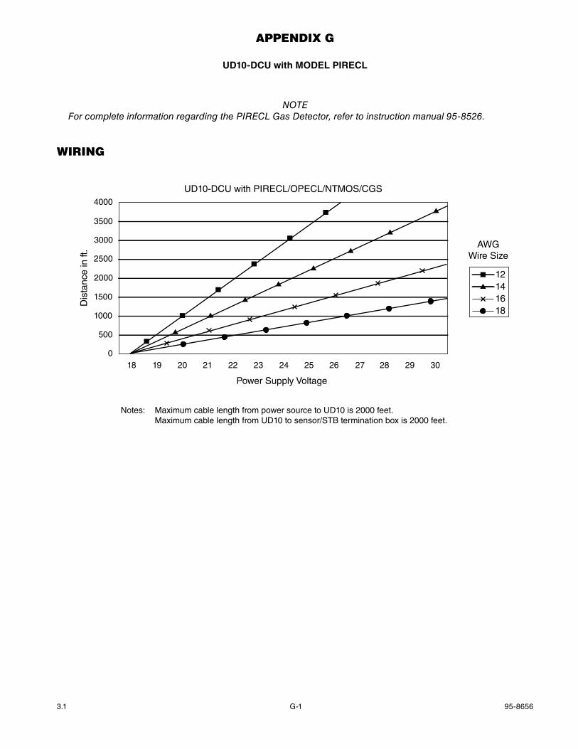
UD10-DCU with mODEL PIRECL
noTeFor complete information regarding the PIReCL Gas Detector, refer to instruction manual 95-8526.
WirinG
4000
3500
3000
2500
2000
1500
1000
500
018 19 20 21 22 23 24 25 26 27 28 29 30
Power Supply Voltage
Dis
tanc
e in
ft.
UD10-DCU with PIRECL/OPECL/NTMOS/CGS
12141618
AWGWire Size
Notes: Maximum cable length from power source to UD10 is 2000 feet. Maximum cable length from UD10 to sensor/STB termination box is 2000 feet.
G-2 95-86563.1
24 VDC –
24 VDC –
24 VDC +
24 VDC +
CALIBRATE
4-20 MA +
4-20 MA –
RS-485 A
RS-485 B
RELAY POWER (RED)
FAULT (ORANGE)
LOW ALARM (WHITE)
HIGH ALARM (YELLOW)
WIRING TO OPTIONALRELAY BOARD
NO USER CONNECTION
1
2
3
4
5
6
7
8
9
10
11
12
13
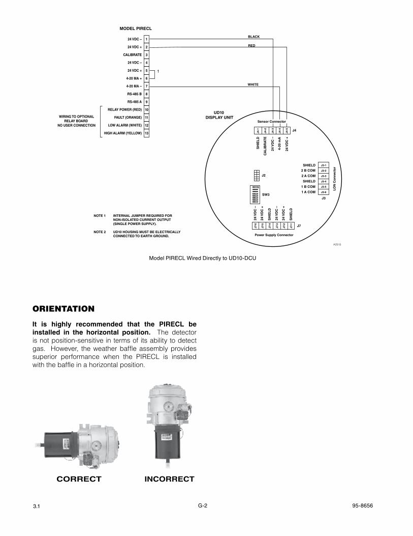
MODEL PIRECL
A2515
BLACK
WHITE
RED
NOTE 1 INTERNAL JUMPER REQUIRED FOR NON-ISOLATED CURRENT OUTPUT (SINGLE POWER SUPPLY).
NOTE 2 UD10 HOUSING MUST BE ELECTRICALLY CONNECTED TO EARTH GROUND.
1
Sensor Connector
Power Supply Connector
LON
Co
nn
ecto
r
J4
J3
J7
24 V
DC
–
24 V
DC
+
SH
IEL
D
24 V
DC
–
24 V
DC
+
SH
IEL
D
SH
IEL
D
CA
LIB
RA
TE
24 V
DC
–
4-20
mA
24 V
DC
+
J4-1
J4-2
J4-3
J4-4
J4-5
J7-6
J7-5
J7-4
J7-3
J7-2
J7-1
SHIELD
2 B COM
2 A COM
SHIELD
1 B COM
1 A COM
J3-1
J3-2
J3-3
J3-4
J3-5
J3-6
UD10 DISPLAY UNIT
SW3
J2
ON
Model PIRECL Wired Directly to UD10-DCU
orientAtion
It is highly recommended that the PIRECL be installed in the horizontal position. The detector is not position-sensitive in terms of its ability to detect gas. However, the weather baffle assembly provides superior performance when the PIRECL is installed with the baffle in a horizontal position.
CORRECT INCORRECT
G-3 95-86563.1
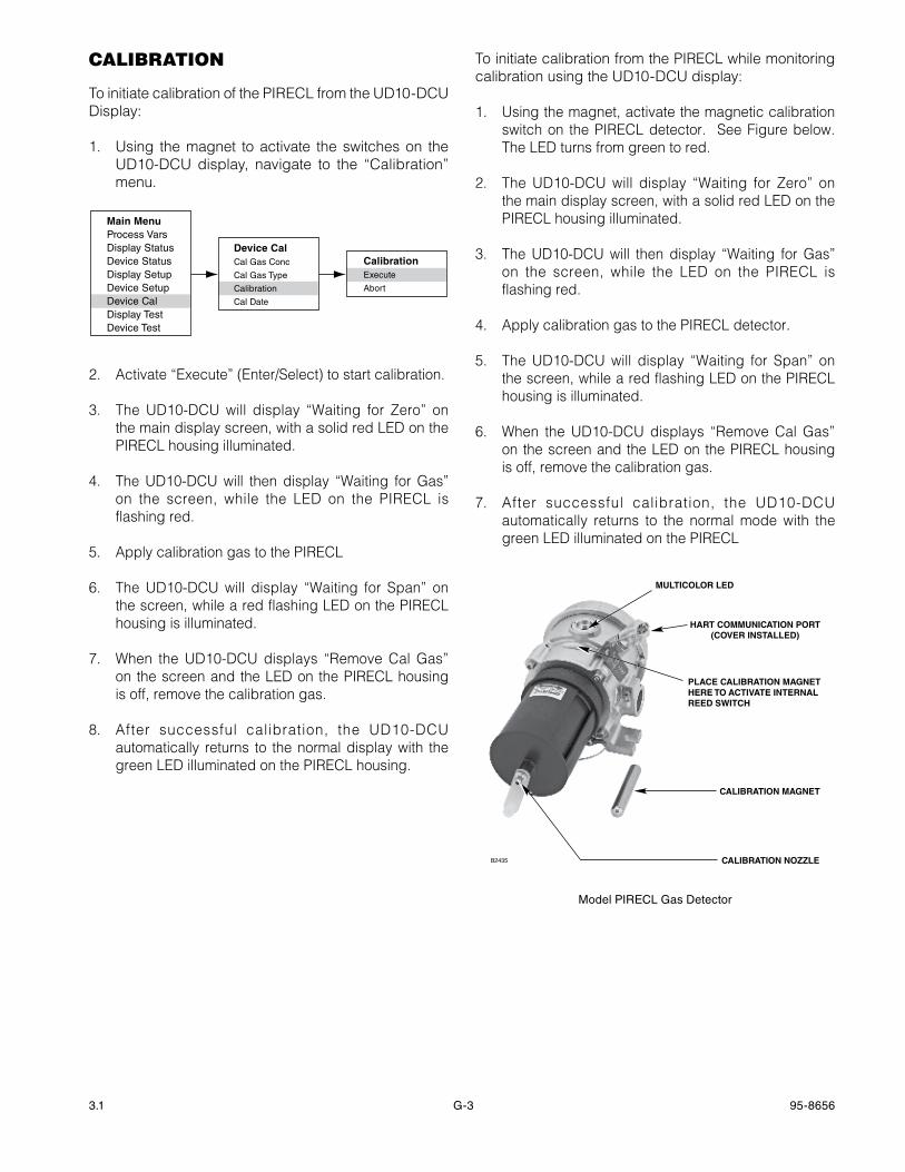
cAlibrAtion
To initiate calibration of the PIRECL from the UD10-DCU Display:
1. Using the magnet to activate the switches on the UD10-DCU display, navigate to the “Calibration” menu.
Main MenuProcess VarsDisplay StatusDevice StatusDisplay SetupDevice SetupDevice CalDisplay TestDevice Test
Device CalCal Gas Conc
Cal Gas Type
Calibration
Cal Date
CalibrationExecute
Abort
2. Activate “Execute” (Enter/Select) to start calibration.
3. The UD10-DCU will display “Waiting for Zero” on the main display screen, with a solid red LED on the PIRECL housing illuminated.
4. The UD10-DCU will then display “Waiting for Gas” on the screen, while the LED on the PIRECL is flashing red.
5. Apply calibration gas to the PIRECL
6. The UD10-DCU will display “Waiting for Span” on the screen, while a red flashing LED on the PIRECL housing is illuminated.
7. When the UD10-DCU displays “Remove Cal Gas” on the screen and the LED on the PIRECL housing is off, remove the calibration gas.
8. After successful calibration, the UD10-DCU automatically returns to the normal display with the green LED illuminated on the PIRECL housing.
To initiate calibration from the PIRECL while monitoring calibration using the UD10-DCU display:
1. Using the magnet, activate the magnetic calibration switch on the PIRECL detector. See Figure below. The LED turns from green to red.
2. The UD10-DCU will display “Waiting for Zero” on the main display screen, with a solid red LED on the PIRECL housing illuminated.
3. The UD10-DCU will then display “Waiting for Gas” on the screen, while the LED on the PIRECL is flashing red.
4. Apply calibration gas to the PIRECL detector.
5. The UD10-DCU will display “Waiting for Span” on the screen, while a red flashing LED on the PIRECL housing is illuminated.
6. When the UD10-DCU displays “Remove Cal Gas” on the screen and the LED on the PIRECL housing is off, remove the calibration gas.
7. After successful calibration, the UD10-DCU automatically returns to the normal mode with the green LED illuminated on the PIRECL
CALIBRATION MAGNET
CALIBRATION NOZZLE
MULTICOLOR LED
HART COMMUNICATION PORT(COVER INSTALLED)
PLACE CALIBRATION MAGNETHERE TO ACTIVATE INTERNALREED SWITCH
B2435
Model PIRECL Gas Detector

G-4 95-86563.1
menu structure
UD10-DCU with model PIRECL
Refer to the following menu when using the UD10-DCU’s LCD display and internal magnetic switches.
menu HeLpStatus menus only allow the user to view the data. The Setup menus allow the user to both view and edit the data.
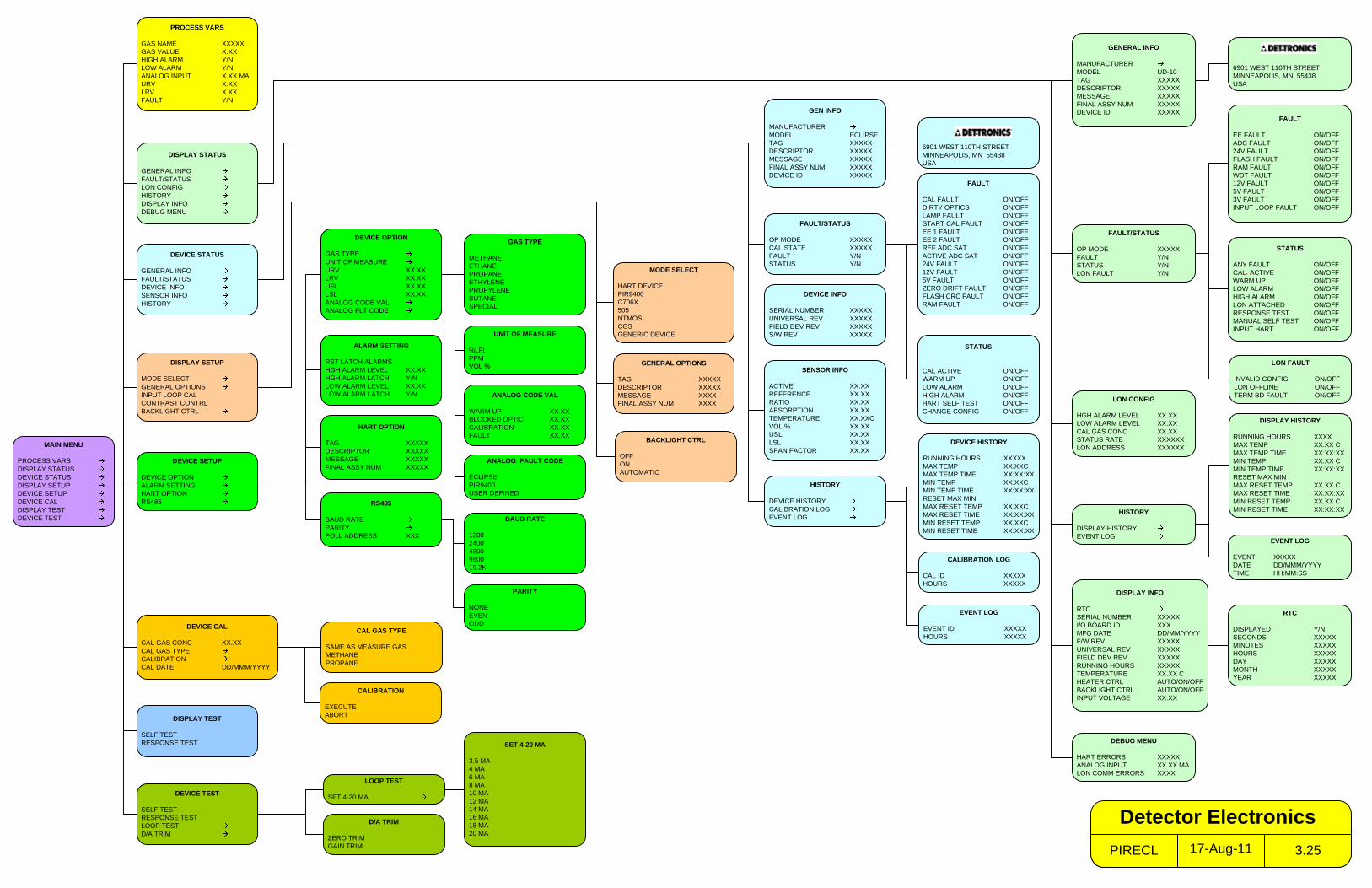
MAIN MENU
PROCESS VARSDISPLAY STATUSDEVICE STATUSDISPLAY SETUPDEVICE SETUPDEVICE CALDISPLAY TESTDEVICE TEST
PROCESS VARS
GAS NAME XXXXXGAS VALUE X.XXHIGH ALARM Y/NLOW ALARM Y/NANALOG INPUT X.XX MAURV X.XXLRV X.XXFAULT Y/N
DISPLAY SETUP
MODE SELECTGENERAL OPTIONSINPUT LOOP CALCONTRAST CONTRLBACKLIGHT CTRL
DISPLAY TEST
SELF TESTRESPONSE TEST
FAULT/STATUS
OP MODE XXXXXFAULT Y/NSTATUS Y/NLON FAULT Y/N
HISTORY
DISPLAY HISTORYEVENT LOG
DISPLAY INFO
RTCSERIAL NUMBER XXXXXI/O BOARD ID XXXMFG DATE DD/MM/YYYYF/W REV XXXXXUNIVERSAL REV XXXXXFIELD DEV REV XXXXXRUNNING HOURS XXXXXTEMPERATURE XX.XX CHEATER CTRL AUTO/ON/OFFBACKLIGHT CTRL AUTO/ON/OFFINPUT VOLTAGE XX.XX
6901 WEST 110TH STREETMINNEAPOLIS, MN 55438USA
EVENT LOG
EVENT XXXXXDATE DD/MMM/YYYYTIME HH:MM:SS
RTC
DISPLAYED Y/NSECONDS XXXXXMINUTES XXXXXHOURS XXXXXDAY XXXXXMONTH XXXXXYEAR XXXXX
SENSOR INFO
ACTIVE XX.XXREFERENCE XX.XXRATIO XX.XXABSORPTION XX.XXTEMPERATURE XX.XXCVOL % XX.XXUSL XX.XXLSL XX.XXSPAN FACTOR XX.XX
FAULT/STATUS
OP MODE XXXXXCAL STATE XXXXXFAULT Y/NSTATUS Y/N
GEN INFO
MANUFACTURERMODEL ECLIPSETAG XXXXXDESCRIPTOR XXXXXMESSAGE XXXXXFINAL ASSY NUM XXXXXDEVICE ID XXXXX
HISTORY
DEVICE HISTORYCALIBRATION LOGEVENT LOG
DEVICE INFO
SERIAL NUMBER XXXXXUNIVERSAL REV XXXXXFIELD DEV REV XXXXXS/W REV XXXXX
DEVICE STATUS
GENERAL INFOFAULT/STATUSDEVICE INFOSENSOR INFOHISTORY
EVENT LOG
EVENT ID XXXXXHOURS XXXXX
CALIBRATION LOG
CAL ID XXXXXHOURS XXXXX
STATUS
CAL ACTIVE ON/OFFWARM UP ON/OFFLOW ALARM ON/OFFHIGH ALARM ON/OFFHART SELF TEST ON/OFFCHANGE CONFIG ON/OFF
FAULT
CAL FAULT ON/OFFDIRTY OPTICS ON/OFFLAMP FAULT ON/OFFSTART CAL FAULT ON/OFFEE 1 FAULT ON/OFFEE 2 FAULT ON/OFFREF ADC SAT ON/OFFACTIVE ADC SAT ON/OFF24V FAULT ON/OFF12V FAULT ON/OFF5V FAULT ON/OFFZERO DRIFT FAULT ON/OFFFLASH CRC FAULT ON/OFFRAM FAULT ON/OFF
D/A TRIM
ZERO TRIMGAIN TRIM
DEVICE TEST
SELF TESTRESPONSE TESTLOOP TESTD/A TRIM
SET 4-20 MA
3.5 MA4 MA6 MA8 MA10 MA12 MA14 MA16 MA18 MA20 MA
LOOP TEST
SET 4-20 MA
DEVICE CAL
CAL GAS CONC XX.XXCAL GAS TYPECALIBRATIONCAL DATE DD/MMM/YYYY
CALIBRATION
EXECUTEABORT
DEVICE SETUP
DEVICE OPTIONALARM SETTINGHART OPTIONRS485
HART OPTION
TAG XXXXXDESCRIPTOR XXXXXMESSAGE XXXXXFINAL ASSY NUM XXXXX
DEVICE OPTION
GAS TYPEUNIT OF MEASUREURV XX.XXLRV XX.XXUSL XX.XXLSL XX.XXANALOG CODE VALANALOG FLT CODE
RS485
BAUD RATEPARITYPOLL ADDRESS XXX
BAUD RATE
120024004800960019.2K
PARITY
NONEEVENODD
ALARM SETTING
RST LATCH ALARMSHGH ALARM LEVEL XX.XXHGH ALARM LATCH Y/NLOW ALARM LEVEL XX.XXLOW ALARM LATCH Y/N
UNIT OF MEASURE
%LFLPPMVOL %
ANALOG CODE VAL
WARM UP XX.XXBLOCKED OPTIC XX.XXCALIBRATION XX.XXFAULT XX.XX
GAS TYPE
METHANEETHANEPROPANEETHYLENEPROPYLENEBUTANESPECIAL
MODE SELECT
HART DEVICEPIR9400C706X505NTMOSCGSGENERIC DEVICE
GENERAL OPTIONS
TAG XXXXXDESCRIPTOR XXXXXMESSAGE XXXXFINAL ASSY NUM XXXX
STATUS
ANY FAULT ON/OFFCAL. ACTIVE ON/OFFWARM UP ON/OFFLOW ALARM ON/OFFHIGH ALARM ON/OFFLON ATTACHED ON/OFFRESPONSE TEST ON/OFFMANUAL SELF TEST ON/OFFINPUT HART ON/OFF
GENERAL INFO
MANUFACTURERMODEL UD-10TAG XXXXXDESCRIPTOR XXXXXMESSAGE XXXXXFINAL ASSY NUM XXXXXDEVICE ID XXXXX
DEVICE HISTORY
RUNNING HOURS XXXXXMAX TEMP XX.XXCMAX TEMP TIME XX:XX:XXMIN TEMP XX.XXCMIN TEMP TIME XX:XX:XXRESET MAX MINMAX RESET TEMP XX.XXCMAX RESET TIME XX:XX:XXMIN RESET TEMP XX.XXCMIN RESET TIME XX:XX:XX
ANALOG FAULT CODE
ECLIPSEPIR9400USER DEFINED
CAL GAS TYPE
SAME AS MEASURE GASMETHANEPROPANE
DISPLAY STATUS
GENERAL INFOFAULT/STATUSLON CONFIGHISTORYDISPLAY INFODEBUG MENU
6901 WEST 110TH STREETMINNEAPOLIS, MN 55438USA
DEBUG MENU
HART ERRORS XXXXXANALOG INPUT XX.XX MALON COMM ERRORS XXXX
FAULT
EE FAULT ON/OFFADC FAULT ON/OFF24V FAULT ON/OFFFLASH FAULT ON/OFFRAM FAULT ON/OFFWDT FAULT ON/OFF12V FAULT ON/OFF5V FAULT ON/OFF3V FAULT ON/OFFINPUT LOOP FAULT ON/OFF
LON CONFIG
HGH ALARM LEVEL XX.XXLOW ALARM LEVEL XX.XXCAL GAS CONC XX.XXSTATUS RATE XXXXXXLON ADDRESS XXXXXX
LON FAULT
INVALID CONFIG ON/OFFLON OFFLINE ON/OFFTERM BD FAULT ON/OFF
BACKLIGHT CTRL
OFFONAUTOMATIC
DISPLAY HISTORY
RUNNING HOURS XXXXMAX TEMP XX.XX CMAX TEMP TIME XX:XX:XXMIN TEMP XX.XX CMIN TEMP TIME XX:XX:XXRESET MAX MINMAX RESET TEMP XX.XX CMAX RESET TIME XX:XX:XXMIN RESET TEMP XX.XX CMIN RESET TIME XX:XX:XX
17-Aug-11PIRECL 3.25
Detector Electronics
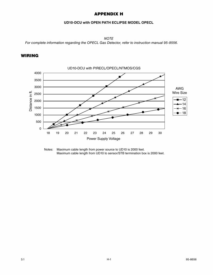
H-1 95-86563.1
AppenDix h
UD10-DCU with OPEN PaTh ECLIPSE mODEL OPECL
noTeFor complete information regarding the oPeCL Gas Detector, refer to instruction manual 95-8556.
WirinG
4000
3500
3000
2500
2000
1500
1000
500
018 19 20 21 22 23 24 25 26 27 28 29 30
Power Supply Voltage
Dis
tanc
e in
ft.
UD10-DCU with PIRECL/OPECL/NTMOS/CGS
12141618
AWGWire Size
Notes: Maximum cable length from power source to UD10 is 2000 feet. Maximum cable length from UD10 to sensor/STB termination box is 2000 feet.
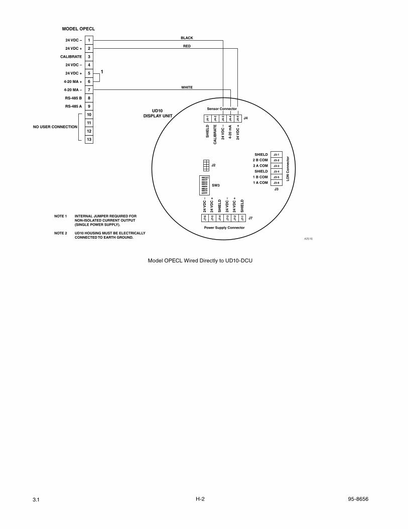
H-2 95-86563.1
MODEL OPECL
24 VDC –
24 VDC –
24 VDC +
24 VDC +
CALIBRATE
4-20 MA +
4-20 MA –
RS-485 A
RS-485 B
NO USER CONNECTION
1
2
3
4
5
6
7
8
9
10
11
12
13
1
NOTE 1 INTERNAL JUMPER REQUIRED FOR NON-ISOLATED CURRENT OUTPUT (SINGLE POWER SUPPLY).
NOTE 2 UD10 HOUSING MUST BE ELECTRICALLY CONNECTED TO EARTH GROUND. A2516
BLACK
WHITE
RED
Sensor Connector
Power Supply Connector
LON
Co
nn
ecto
r
J4
J3
J7
24 V
DC
–
24 V
DC
+
SH
IEL
D
24 V
DC
–
24 V
DC
+
SH
IEL
D
SH
IEL
D
CA
LIB
RA
TE
24 V
DC
–
4-20
mA
24 V
DC
+
J4-1
J4-2
J4-3
J4-4
J4-5
J7-6
J7-5
J7-4
J7-3
J7-2
J7-1
SHIELD
2 B COM
2 A COM
SHIELD
1 B COM
1 A COM
J3-1
J3-2
J3-3
J3-4
J3-5
J3-6
UD10 DISPLAY UNIT
SW3
J2
ON
Model OPECL Wired Directly to UD10-DCU
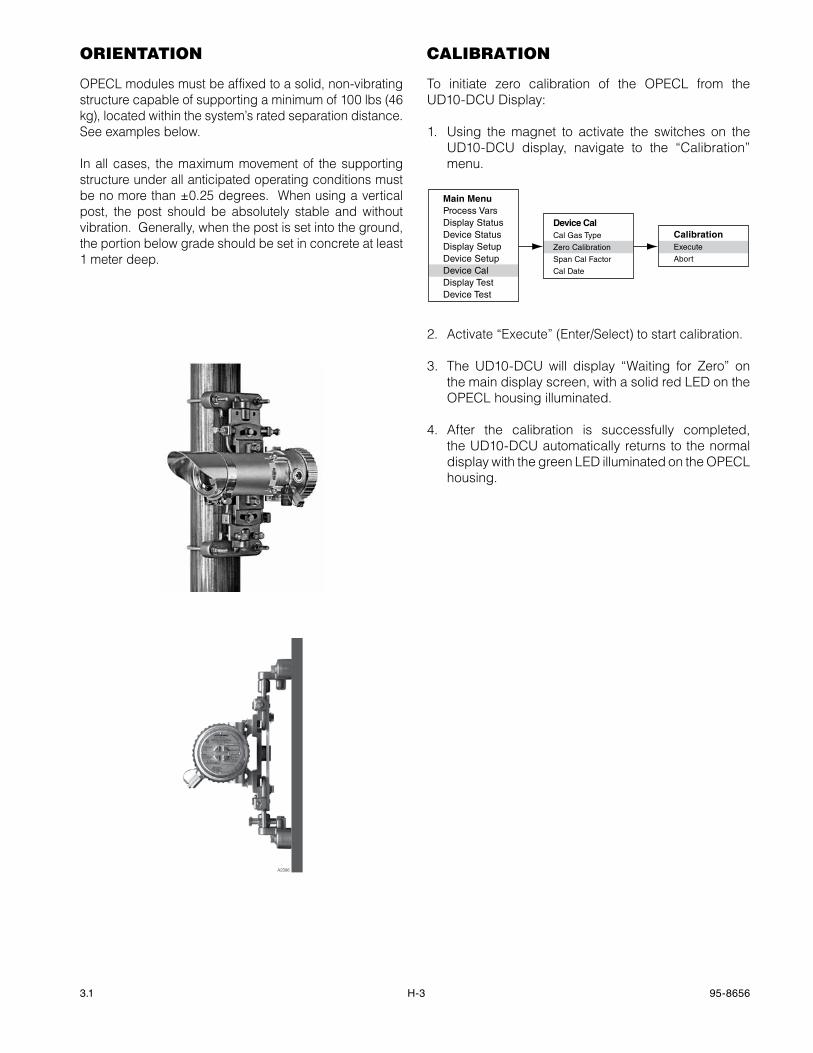
H-3 95-86563.1
orientAtion
OPECL modules must be affixed to a solid, non-vibrating structure capable of supporting a minimum of 100 lbs (46 kg), located within the system’s rated separation distance. See examples below.
In all cases, the maximum movement of the supporting structure under all anticipated operating conditions must be no more than ±0.25 degrees. When using a vertical post, the post should be absolutely stable and without vibration. Generally, when the post is set into the ground, the portion below grade should be set in concrete at least 1 meter deep.
cAlibrAtion
To initiate zero calibration of the OPECL from the UD10-DCU Display:
1. Using the magnet to activate the switches on the UD10-DCU display, navigate to the “Calibration” menu.
Main MenuProcess VarsDisplay StatusDevice StatusDisplay SetupDevice SetupDevice CalDisplay TestDevice Test
Device CalCal Gas Type
Zero Calibration
Span Cal Factor
Cal Date
CalibrationExecute
Abort
2. Activate “Execute” (Enter/Select) to start calibration.
3. The UD10-DCU will display “Waiting for Zero” on the main display screen, with a solid red LED on the OPECL housing illuminated.
4. After the calibration is successfully completed, the UD10-DCU automatically returns to the normal display with the green LED illuminated on the OPECL housing.
A2306
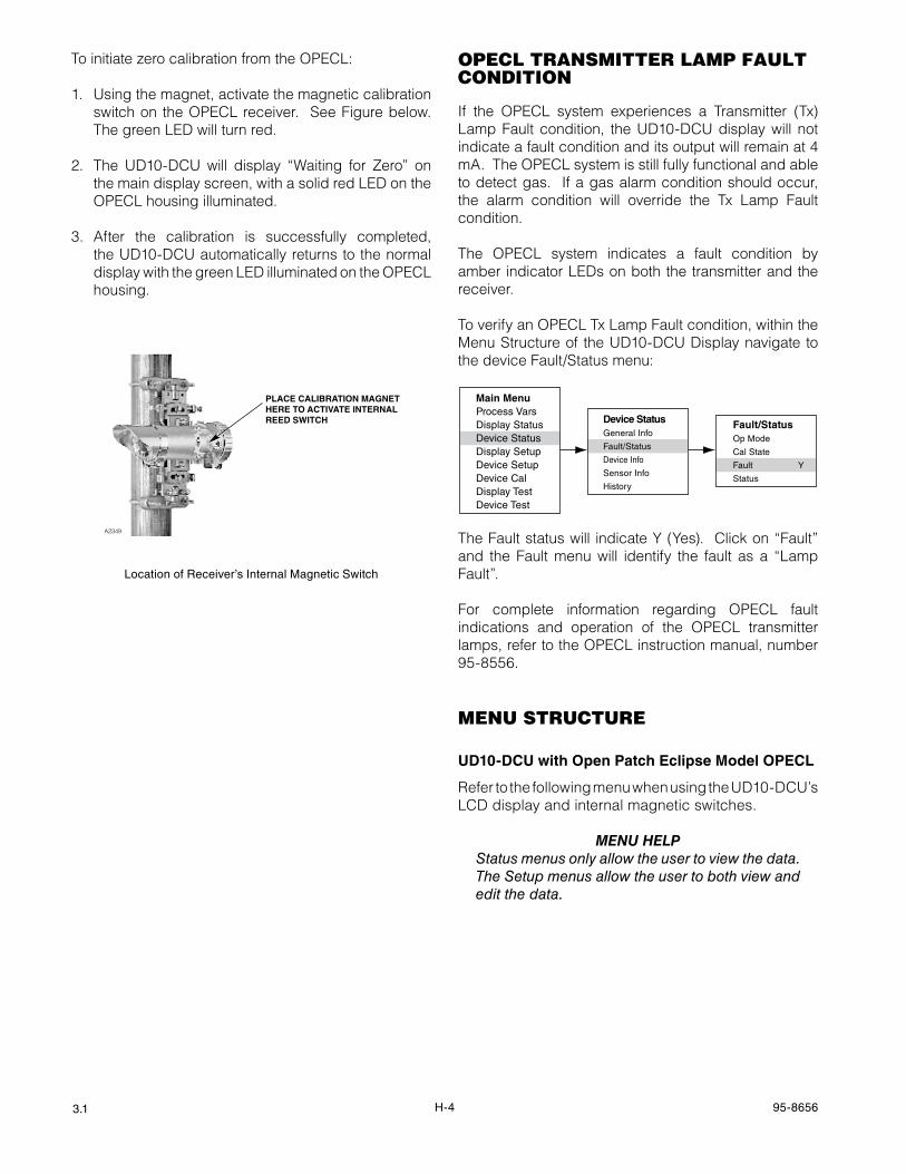
H-4 95-86563.1
To initiate zero calibration from the OPECL:
1. Using the magnet, activate the magnetic calibration switch on the OPECL receiver. See Figure below. The green LED will turn red.
2. The UD10-DCU will display “Waiting for Zero” on the main display screen, with a solid red LED on the OPECL housing illuminated.
3. After the calibration is successfully completed, the UD10-DCU automatically returns to the normal display with the green LED illuminated on the OPECL housing.
opecl trAnsmitter lAmp fAult conDition
If the OPECL system experiences a Transmitter (Tx) Lamp Fault condition, the UD10-DCU display will not indicate a fault condition and its output will remain at 4 mA. The OPECL system is still fully functional and able to detect gas. If a gas alarm condition should occur, the alarm condition will override the Tx Lamp Fault condition.
The OPECL system indicates a fault condition by amber indicator LEDs on both the transmitter and the receiver.
To verify an OPECL Tx Lamp Fault condition, within the Menu Structure of the UD10-DCU Display navigate to the device Fault/Status menu:
TheFaultstatuswill indicateY(Yes).Clickon“Fault”and the Fault menu will identify the fault as a “Lamp Fault”.
For complete information regarding OPECL fault indications and operation of the OPECL transmitter lamps, refer to the OPECL instruction manual, number 95-8556.
menu structure
UD10-DCU with Open Patch Eclipse model OPECL
Refer to the following menu when using the UD10-DCU’s LCD display and internal magnetic switches.
menu HeLpStatus menus only allow the user to view the data. The Setup menus allow the user to both view and edit the data.
Location of Receiver’s Internal Magnetic Switch
PLACE CALIBRATION MAGNETHERE TO ACTIVATE INTERNALREED SWITCH
A2349
Main MenuProcess VarsDisplay StatusDevice StatusDisplay SetupDevice SetupDevice CalDisplay TestDevice Test
Device StatusGeneral Info
Fault/Status
Device Info
Sensor Info
History
Fault/StatusOp Mode
Cal State
Fault Y
Status
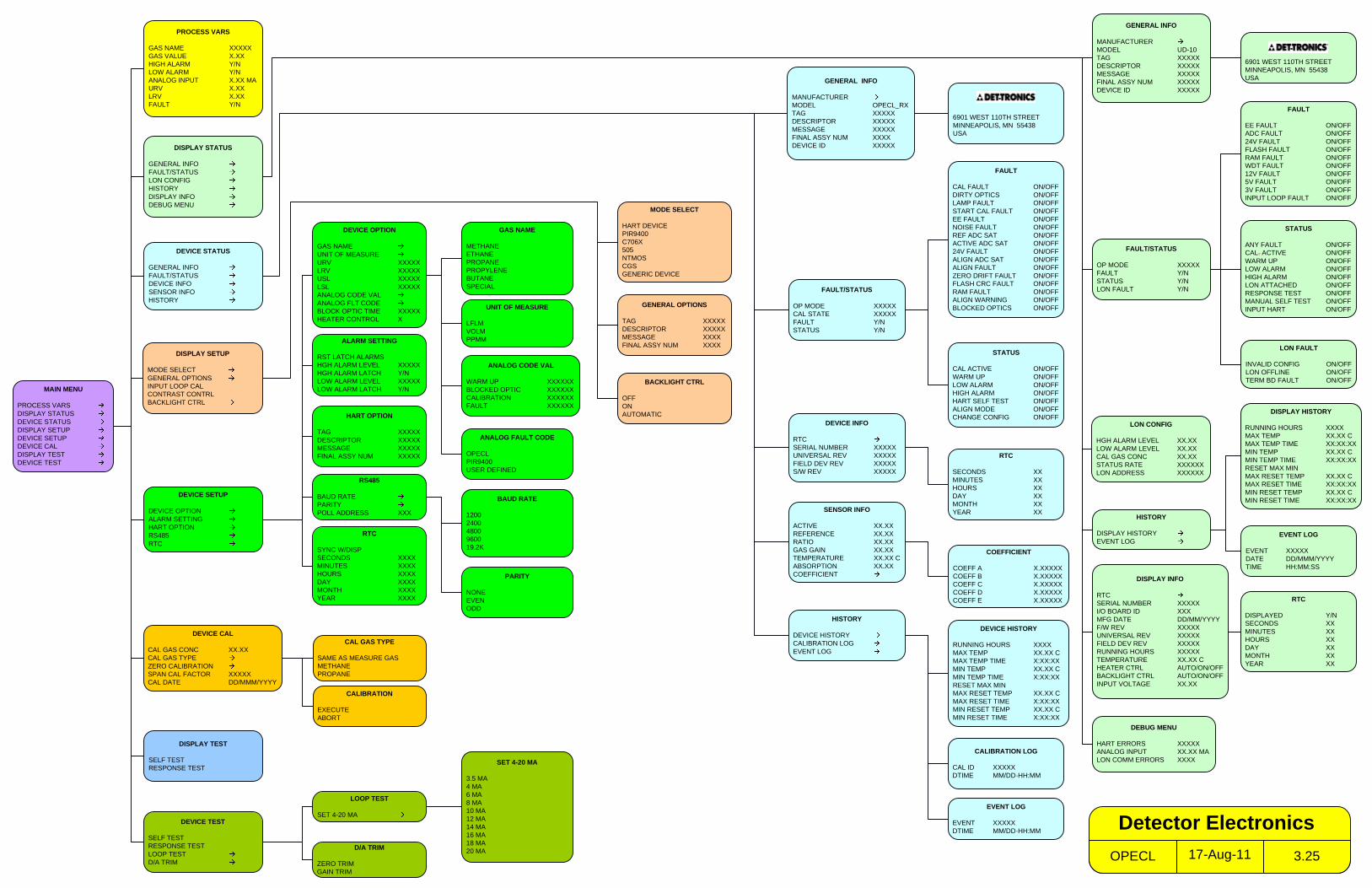
MAIN MENU
PROCESS VARSDISPLAY STATUSDEVICE STATUSDISPLAY SETUPDEVICE SETUPDEVICE CALDISPLAY TESTDEVICE TEST
PROCESS VARS
GAS NAME XXXXXGAS VALUE X.XXHIGH ALARM Y/NLOW ALARM Y/NANALOG INPUT X.XX MAURV X.XXLRV X.XXFAULT Y/N
HISTORY
DISPLAY HISTORYEVENT LOG
DISPLAY INFO
RTCSERIAL NUMBER XXXXXI/O BOARD ID XXXMFG DATE DD/MM/YYYYF/W REV XXXXXUNIVERSAL REV XXXXXFIELD DEV REV XXXXXRUNNING HOURS XXXXXTEMPERATURE XX.XX CHEATER CTRL AUTO/ON/OFFBACKLIGHT CTRL AUTO/ON/OFFINPUT VOLTAGE XX.XX
EVENT LOG
EVENT XXXXXDATE DD/MMM/YYYYTIME HH:MM:SS
RTC
DISPLAYED Y/NSECONDS XXMINUTES XXHOURS XXDAY XXMONTH XXYEAR XX
GENERAL OPTIONS
TAG XXXXXDESCRIPTOR XXXXXMESSAGE XXXXFINAL ASSY NUM XXXX
RTC
SECONDS XXMINUTES XXHOURS XXDAY XXMONTH XXYEAR XX
HISTORY
DEVICE HISTORYCALIBRATION LOGEVENT LOG
DEVICE HISTORY
RUNNING HOURS XXXXMAX TEMP XX.XX CMAX TEMP TIME X:XX:XXMIN TEMP XX.XX CMIN TEMP TIME X:XX:XXRESET MAX MINMAX RESET TEMP XX.XX CMAX RESET TIME X:XX:XXMIN RESET TEMP XX.XX CMIN RESET TIME X:XX:XX
GENERAL INFO
MANUFACTURERMODEL OPECL_RXTAG XXXXXDESCRIPTOR XXXXXMESSAGE XXXXXFINAL ASSY NUM XXXXDEVICE ID XXXXX
FAULT/STATUS
OP MODE XXXXXCAL STATE XXXXXFAULT Y/NSTATUS Y/N
DEVICE INFO
RTCSERIAL NUMBER XXXXXUNIVERSAL REV XXXXXFIELD DEV REV XXXXXS/W REV XXXXX
SENSOR INFO
ACTIVE XX.XXREFERENCE XX.XXRATIO XX.XXGAS GAIN XX.XXTEMPERATURE XX.XX CABSORPTION XX.XXCOEFFICIENT
COEFFICIENT
COEFF A X.XXXXXCOEFF B X.XXXXXCOEFF C X.XXXXXCOEFF D X.XXXXXCOEFF E X.XXXXX
DEVICE STATUS
GENERAL INFOFAULT/STATUSDEVICE INFOSENSOR INFOHISTORY
EVENT LOG
EVENT XXXXXDTIME MM/DD-HH:MM
CALIBRATION LOG
CAL ID XXXXXDTIME MM/DD-HH:MM
STATUS
CAL ACTIVE ON/OFFWARM UP ON/OFFLOW ALARM ON/OFFHIGH ALARM ON/OFFHART SELF TEST ON/OFFALIGN MODE ON/OFFCHANGE CONFIG ON/OFF
FAULT
CAL FAULT ON/OFF DIRTY OPTICS ON/OFF LAMP FAULT ON/OFF START CAL FAULT ON/OFF EE FAULT ON/OFF NOISE FAULT ON/OFF REF ADC SAT ON/OFF ACTIVE ADC SAT ON/OFF 24V FAULT ON/OFFALIGN ADC SAT ON/OFFALIGN FAULT ON/OFFZERO DRIFT FAULT ON/OFFFLASH CRC FAULT ON/OFF RAM FAULT ON/OFFALIGN WARNING ON/OFFBLOCKED OPTICS ON/OFF
DEVICE SETUP
DEVICE OPTIONALARM SETTINGHART OPTIONRS485RTC
HART OPTION
TAG XXXXXDESCRIPTOR XXXXXMESSAGE XXXXXFINAL ASSY NUM XXXXX
DEVICE OPTION
GAS NAMEUNIT OF MEASUREURV XXXXXLRV XXXXXUSL XXXXXLSL XXXXXANALOG CODE VALANALOG FLT CODEBLOCK OPTIC TIME XXXXXHEATER CONTROL X
RS485
BAUD RATEPARITYPOLL ADDRESS XXX
BAUD RATE
120024004800960019.2K
PARITY
NONEEVEN ODD
ALARM SETTING
RST LATCH ALARMSHGH ALARM LEVEL XXXXXHGH ALARM LATCH Y/NLOW ALARM LEVEL XXXXXLOW ALARM LATCH Y/N
ANALOG CODE VAL
WARM UP XXXXXXBLOCKED OPTIC XXXXXXCALIBRATION XXXXXXFAULT XXXXXX
GAS NAME
METHANEETHANEPROPANEPROPYLENEBUTANESPECIAL
ANALOG FAULT CODE
OPECLPIR9400USER DEFINED
RTC
SYNC W/DISPSECONDS XXXXMINUTES XXXXHOURS XXXXDAY XXXXMONTH XXXXYEAR XXXX
D/A TRIM
ZERO TRIMGAIN TRIM
DEVICE TEST
SELF TESTRESPONSE TESTLOOP TESTD/A TRIM
SET 4-20 MA
3.5 MA4 MA6 MA8 MA10 MA12 MA14 MA16 MA18 MA20 MA
LOOP TEST
SET 4-20 MA
DEVICE CAL
CAL GAS CONC XX.XXCAL GAS TYPEZERO CALIBRATIONSPAN CAL FACTOR XXXXXCAL DATE DD/MMM/YYYY
CALIBRATION
EXECUTEABORT
UNIT OF MEASURE
LFLMVOLMPPMM
DISPLAY TEST
SELF TESTRESPONSE TEST
DISPLAY SETUP
MODE SELECTGENERAL OPTIONSINPUT LOOP CALCONTRAST CONTRLBACKLIGHT CTRL
MODE SELECT
HART DEVICEPIR9400C706X505NTMOSCGSGENERIC DEVICE
DISPLAY STATUS
GENERAL INFOFAULT/STATUSLON CONFIGHISTORYDISPLAY INFODEBUG MENU
GENERAL INFO
MANUFACTURERMODEL UD-10TAG XXXXXDESCRIPTOR XXXXXMESSAGE XXXXXFINAL ASSY NUM XXXXXDEVICE ID XXXXX
STATUS
ANY FAULT ON/OFFCAL. ACTIVE ON/OFFWARM UP ON/OFFLOW ALARM ON/OFFHIGH ALARM ON/OFFLON ATTACHED ON/OFFRESPONSE TEST ON/OFFMANUAL SELF TEST ON/OFFINPUT HART ON/OFF
FAULT/STATUS
OP MODE XXXXXFAULT Y/NSTATUS Y/NLON FAULT Y/N
6901 WEST 110TH STREETMINNEAPOLIS, MN 55438USA
6901 WEST 110TH STREETMINNEAPOLIS, MN 55438USA
CAL GAS TYPE
SAME AS MEASURE GASMETHANEPROPANE
DEBUG MENU
HART ERRORS XXXXXANALOG INPUT XX.XX MALON COMM ERRORS XXXX
FAULT
EE FAULT ON/OFFADC FAULT ON/OFF24V FAULT ON/OFFFLASH FAULT ON/OFFRAM FAULT ON/OFFWDT FAULT ON/OFF12V FAULT ON/OFF5V FAULT ON/OFF3V FAULT ON/OFFINPUT LOOP FAULT ON/OFF
LON CONFIG
HGH ALARM LEVEL XX.XXLOW ALARM LEVEL XX.XXCAL GAS CONC XX.XXSTATUS RATE XXXXXXLON ADDRESS XXXXXX
LON FAULT
INVALID CONFIG ON/OFFLON OFFLINE ON/OFFTERM BD FAULT ON/OFFBACKLIGHT CTRL
OFFONAUTOMATIC DISPLAY HISTORY
RUNNING HOURS XXXXMAX TEMP XX.XX CMAX TEMP TIME XX:XX:XXMIN TEMP XX.XX CMIN TEMP TIME XX:XX:XXRESET MAX MINMAX RESET TEMP XX.XX CMAX RESET TIME XX:XX:XXMIN RESET TEMP XX.XX CMIN RESET TIME XX:XX:XX
17-Aug-11OPECL 3.25
Detector Electronics
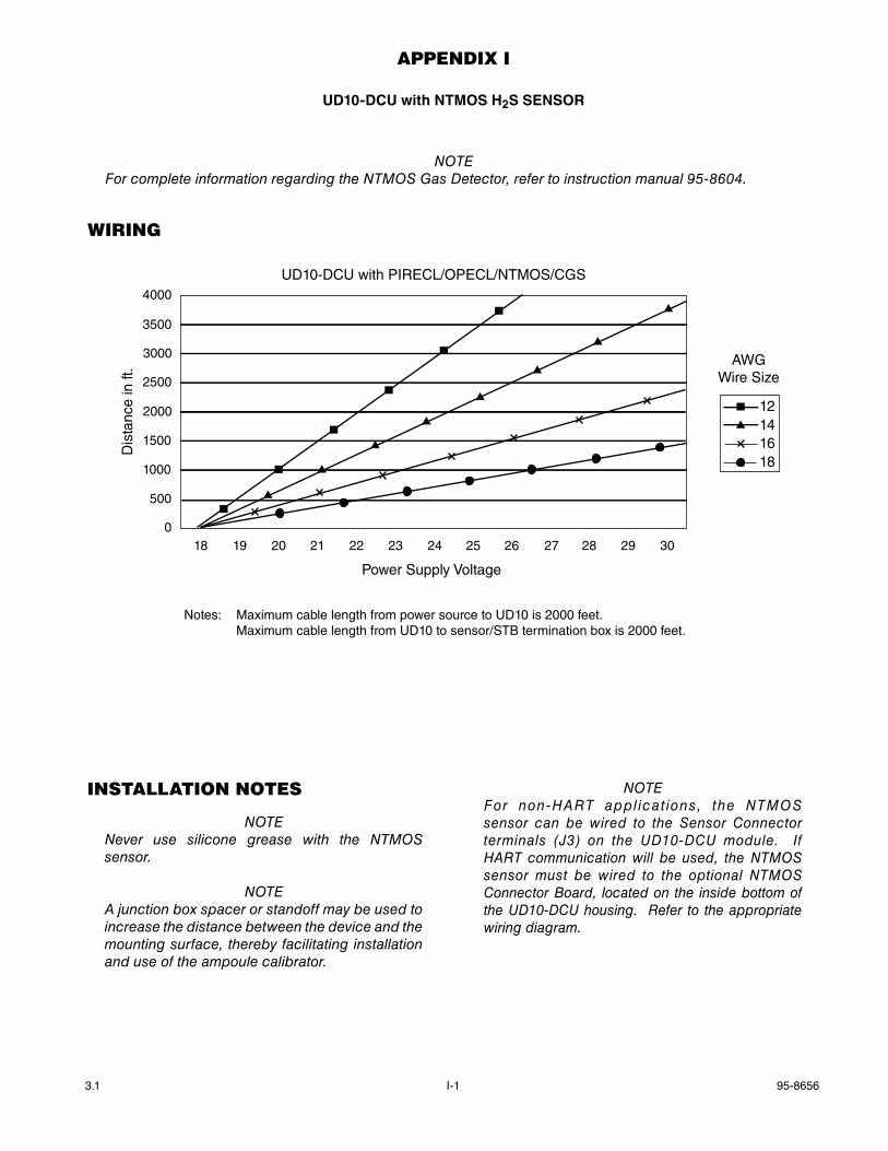
3.1 I-1 95-8656
AppenDix i
UD10-DCU with NTmOS h2S SENSOR
noTeFor complete information regarding the nTMoS Gas Detector, refer to instruction manual 95-8604.
WirinG
4000
3500
3000
2500
2000
1500
1000
500
018 19 20 21 22 23 24 25 26 27 28 29 30
Power Supply Voltage
Dis
tanc
e in
ft.
UD10-DCU with PIRECL/OPECL/NTMOS/CGS
12141618
AWGWire Size
Notes: Maximum cable length from power source to UD10 is 2000 feet. Maximum cable length from UD10 to sensor/STB termination box is 2000 feet.
instAllAtion notes
noTenever use silicone grease with the nTMoS sensor.
noTeA junction box spacer or standoff may be used to increase the distance between the device and the mounting surface, thereby facilitating installation and use of the ampoule calibrator.
noTeFor non-HART appl icat ions, the nTMoS sensor can be wired to the Sensor Connector terminals (J3) on the UD10-DCU module. If HART communication will be used, the nTMoS sensor must be wired to the optional nTMoS Connector Board, located on the inside bottom of the UD10-DCU housing. Refer to the appropriate wiring diagram.
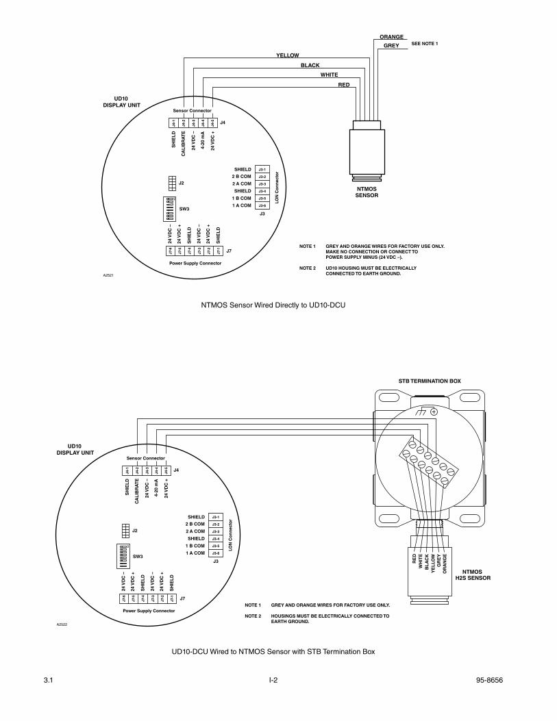
3.1 I-2 95-8656
NTMOSSENSOR
BLACK
RED
GREY
YELLOW
WHITE
ORANGE
NOTE 1 GREY AND ORANGE WIRES FOR FACTORY USE ONLY. MAKE NO CONNECTION OR CONNECT TO POWER SUPPLY MINUS (24 VDC –).
NOTE 2 UD10 HOUSING MUST BE ELECTRICALLY CONNECTED TO EARTH GROUND.A2521
SEE NOTE 1
Sensor Connector
Power Supply Connector
LON
Co
nn
ecto
r
J4
J3
J7
24 V
DC
–
24 V
DC
+
SH
IEL
D
24 V
DC
–
24 V
DC
+
SH
IEL
D
SH
IEL
D
CA
LIB
RA
TE
24 V
DC
–
4-20
mA
24 V
DC
+
J4-1
J4-2
J4-3
J4-4
J4-5
J7-6
J7-5
J7-4
J7-3
J7-2
J7-1
SHIELD
2 B COM
2 A COM
SHIELD
1 B COM
1 A COM
J3-1
J3-2
J3-3
J3-4
J3-5
J3-6
UD10 DISPLAY UNIT
SW3
J2
ON
NTMOS Sensor Wired Directly to UD10-DCU
NOTE 1 GREY AND ORANGE WIRES FOR FACTORY USE ONLY.
NOTE 2 HOUSINGS MUST BE ELECTRICALLY CONNECTED TO EARTH GROUND.
A2522
STB TERMINATION BOX
NTMOS H2S SENSOR
RE
D
BL
AC
KW
HIT
E
YE
LLO
WG
RE
YO
RA
NG
E
Sensor Connector
Power Supply Connector
LON
Co
nn
ecto
r
J4
J3
J7
24 V
DC
–
24 V
DC
+
SH
IEL
D
24 V
DC
–
24 V
DC
+
SH
IEL
D
SH
IEL
D
CA
LIB
RA
TE
24 V
DC
–
4-20
mA
24 V
DC
+
J4-1
J4-2
J4-3
J4-4
J4-5
J7-6
J7-5
J7-4
J7-3
J7-2
J7-1
SHIELD
2 B COM
2 A COM
SHIELD
1 B COM
1 A COM
J3-1
J3-2
J3-3
J3-4
J3-5
J3-6
UD10 DISPLAY UNIT
SW3
J2
ON
UD10-DCU Wired to NTMOS Sensor with STB Termination Box
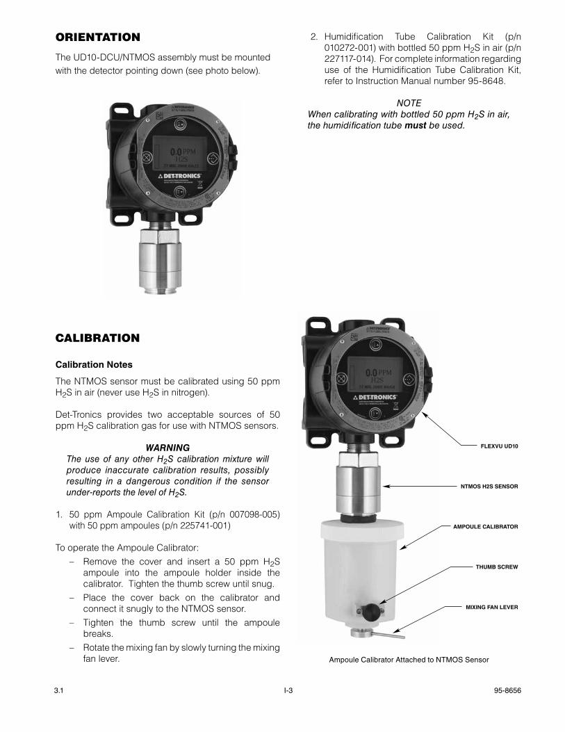
3.1 I-3 95-8656
orientAtion
The UD10-DCU/NTMOS assembly must be mounted with the detector pointing down (see photo below).
cAlibrAtion
Calibration Notes
The NTMOS sensor must be calibrated using 50 ppm H2S in air (never use H2S in nitrogen).
Det-Tronics provides two acceptable sources of 50 ppm H2S calibration gas for use with NTMOS sensors.
WarnIngThe use of any other H2S calibration mixture will produce inaccurate calibration results, possibly resulting in a dangerous condition if the sensor under-reports the level of H2S.
1. 50 ppm Ampoule Calibration Kit (p/n 007098-005) with 50 ppm ampoules (p/n 225741-001)
To operate the Ampoule Calibrator:– Remove the cover and insert a 50 ppm H2S
ampoule into the ampoule holder inside the calibrator. Tighten the thumb screw until snug.
– Place the cover back on the calibrator and connect it snugly to the NTMOS sensor.
– Tighten the thumb screw until the ampoule breaks.
– Rotate the mixing fan by slowly turning the mixing fan lever.
2. Humidification Tube Calibration Kit (p/n 010272-001) with bottled 50 ppm H2S in air (p/n 227117-014). For complete information regarding use of the Humidification Tube Calibration Kit, refer to Instruction Manual number 95-8648.
noTeWhen calibrating with bottled 50 ppm H2S in air, the humidification tube must be used.
FLEXVU UD10
NTMOS H2S SENSOR
AMPOULE CALIBRATOR
THUMB SCREW
MIXING FAN LEVER
Ampoule Calibrator Attached to NTMOS Sensor
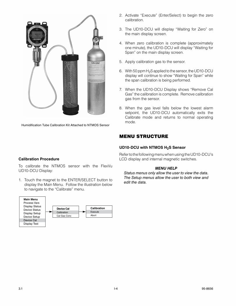
3.1 I-4 95-8656
Calibration Procedure
To calibrate the NTMOS sensor with the FlexVu UD10-DCU Display:
1. Touch the magnet to the ENTER/SELECT button to display the Main Menu. Follow the illustration below to navigate to the “Calibrate” menu.
Main MenuProcess VarsDisplay StatusDevice StatusDisplay SetupDevice SetupDevice CalDisplay Test
Device CalCalibration
Cal Gas Conc
CalibrationExecute
Abort
2. Activate “Execute” (Enter/Select) to begin the zero calibration.
3. The UD10-DCU will display “Waiting for Zero” on the main display screen.
4. When zero calibration is complete (approximately one minute), the UD10-DCU will display “Waiting for Span” on the main display screen.
5. Apply calibration gas to the sensor.
6. With 50 ppm H2S applied to the sensor, the UD10-DCU display will continue to show “Waiting for Span” while the span calibration is being performed.
7. When the UD10-DCU Display shows “Remove Cal Gas” the calibration is complete. Remove calibration gas from the sensor.
8. When the gas level falls below the lowest alarm setpoint, the UD10-DCU automatically exits the Calibrate mode and returns to normal operating mode.
menu structure
UD10-DCU with NTmOS h2S Sensor
Refer to the following menu when using the UD10-DCU’s LCD display and internal magnetic switches.
menu HeLpStatus menus only allow the user to view the data. The Setup menus allow the user to both view and edit the data.
Humidification Tube Calibration Kit Attached to NTMOS Sensor
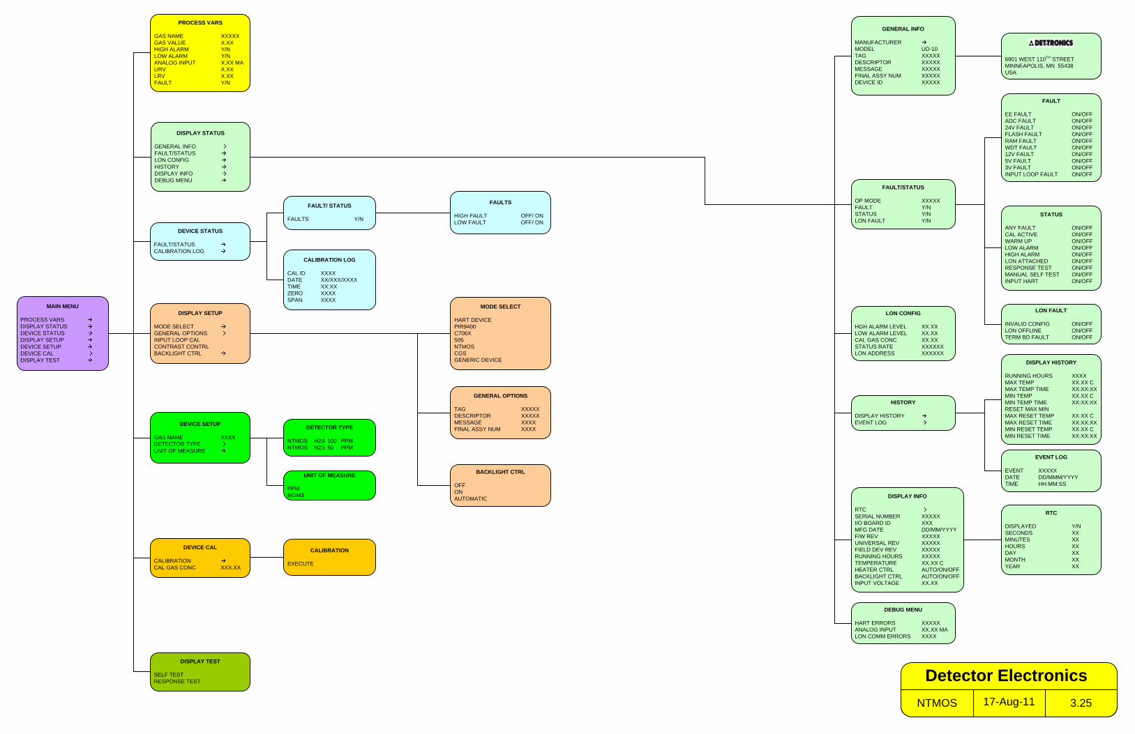
MAIN MENU
PROCESS VARSDISPLAY STATUSDEVICE STATUSDISPLAY SETUPDEVICE SETUPDEVICE CALDISPLAY TEST
PROCESS VARS
GAS NAME XXXXXGAS VALUE X.XXHIGH ALARM Y/NLOW ALARM Y/NANALOG INPUT X.XX MAURV X.XXLRV X.XXFAULT Y/N
DISPLAY STATUS
GENERAL INFOFAULT/STATUSLON CONFIGHISTORYDISPLAY INFODEBUG MENU
DISPLAY SETUP
MODE SELECTGENERAL OPTIONSINPUT LOOP CALCONTRAST CONTRLBACKLIGHT CTRL
DISPLAY TEST
SELF TESTRESPONSE TEST
FAULT/STATUS
OP MODE XXXXXFAULT Y/NSTATUS Y/NLON FAULT Y/N
GENERAL INFO
MANUFACTURERMODEL UD-10TAG XXXXXDESCRIPTOR XXXXXMESSAGE XXXXXFINAL ASSY NUM XXXXXDEVICE ID XXXXX
STATUS
ANY FAULT ON/OFFCAL ACTIVE ON/OFFWARM UP ON/OFFLOW ALARM ON/OFFHIGH ALARM ON/OFFLON ATTACHED ON/OFFRESPONSE TEST ON/OFFMANUAL SELF TEST ON/OFFINPUT HART ON/OFF
DEVICE STATUS
FAULT/STATUSCALIBRATION LOG
CALIBRATION LOG
CAL ID XXXXDATE XX/XXX/XXXXTIME XX:XXZERO XXXXSPAN XXXX
DEVICE SETUP
GAS NAME XXXXDETECTOR TYPEUNIT OF MEASURE
DETECTOR TYPE
NTMOS H2S 100 PPMNTMOS H2S 50 PPM
DEVICE CAL
CALIBRATIONCAL GAS CONC XXX.XX
CALIBRATION
EXECUTE
6901 WEST 110TH STREETMINNEAPOLIS, MN 55438USA
HISTORY
DISPLAY HISTORYEVENT LOG
DISPLAY INFO
RTCSERIAL NUMBER XXXXXI/O BOARD ID XXXMFG DATE DD/MM/YYYYF/W REV XXXXXUNIVERSAL REV XXXXXFIELD DEV REV XXXXXRUNNING HOURS XXXXXTEMPERATURE XX.XX CHEATER CTRL AUTO/ON/OFFBACKLIGHT CTRL AUTO/ON/OFFINPUT VOLTAGE XX.XX
EVENT LOG
EVENT XXXXXDATE DD/MMM/YYYYTIME HH:MM:SS
RTC
DISPLAYED Y/NSECONDS XXMINUTES XXHOURS XXDAY XXMONTH XXYEAR XX
DEBUG MENU
HART ERRORS XXXXXANALOG INPUT XX.XX MALON COMM ERRORS XXXX
FAULT
EE FAULT ON/OFFADC FAULT ON/OFF24V FAULT ON/OFFFLASH FAULT ON/OFFRAM FAULT ON/OFFWDT FAULT ON/OFF12V FAULT ON/OFF5V FAULT ON/OFF3V FAULT ON/OFFINPUT LOOP FAULT ON/OFF
FAULTS
HIGH FAULT OFF/ ONLOW FAULT OFF/ ON
FAULT/ STATUS
FAULTS Y/N
MODE SELECT
HART DEVICEPIR9400C706X505NTMOSCGSGENERIC DEVICE
GENERAL OPTIONS
TAG XXXXXDESCRIPTOR XXXXXMESSAGE XXXXFINAL ASSY NUM XXXX
LON CONFIG
HGH ALARM LEVEL XX.XXLOW ALARM LEVEL XX.XXCAL GAS CONC XX.XXSTATUS RATE XXXXXXLON ADDRESS XXXXXX
LON FAULT
INVALID CONFIG ON/OFFLON OFFLINE ON/OFFTERM BD FAULT ON/OFF
BACKLIGHT CTRL
OFFONAUTOMATIC
DISPLAY HISTORY
RUNNING HOURS XXXXMAX TEMP XX.XX CMAX TEMP TIME XX:XX:XXMIN TEMP XX.XX CMIN TEMP TIME XX:XX:XXRESET MAX MINMAX RESET TEMP XX.XX CMAX RESET TIME XX:XX:XXMIN RESET TEMP XX.XX CMIN RESET TIME XX:XX:XX
17-Aug-11NTMOS 3.25
Detector Electronics
UNIT OF MEASURE
PPMMGM3
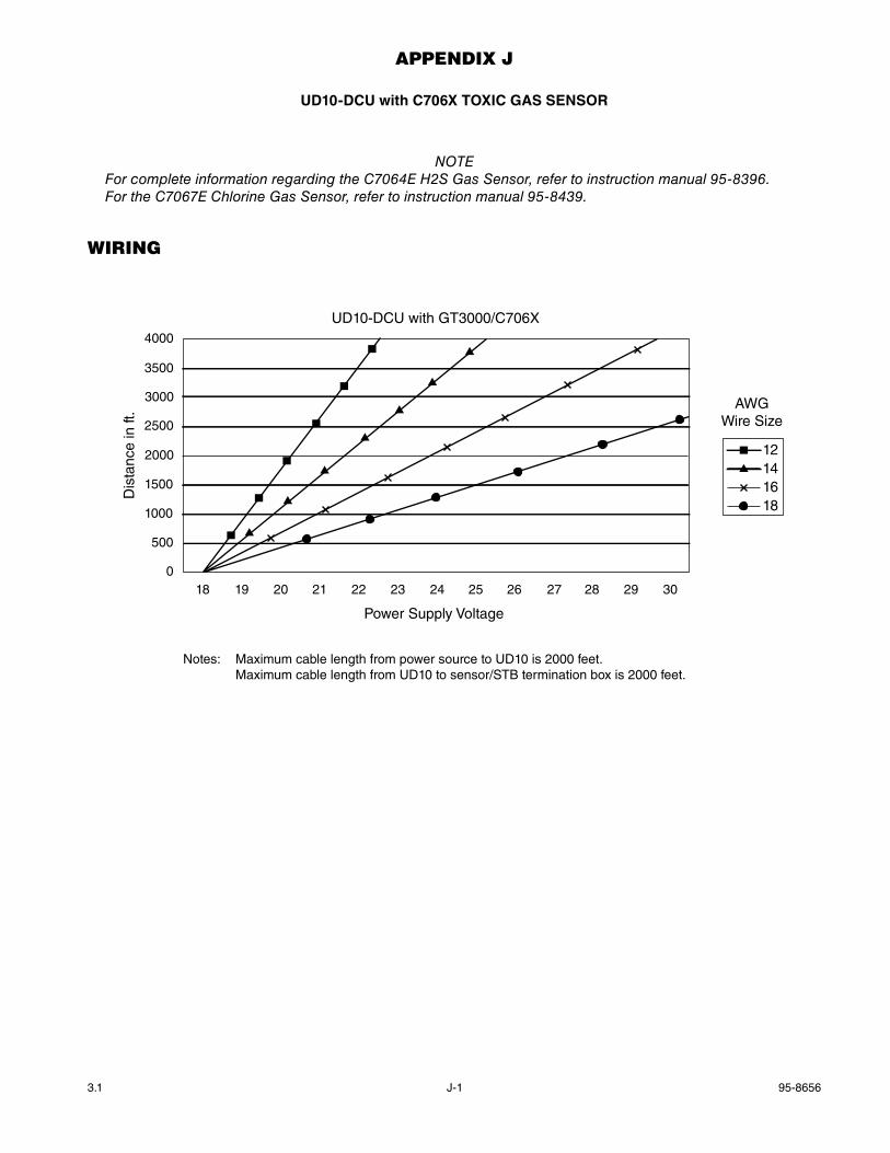
3.1 95-8656J-1
AppenDix J
UD10-DCU with C706x TOxIC gaS SENSOR
noTeFor complete information regarding the C7064e H2S Gas Sensor, refer to instruction manual 95-8396.For the C7067e Chlorine Gas Sensor, refer to instruction manual 95-8439.
WirinG
4000
3500
3000
2500
2000
1500
1000
500
018 19 20 21 22 23 24 25 26 27 28 29 30
Power Supply Voltage
Dis
tanc
e in
ft.
UD10-DCU with GT3000/C706X
12141618
AWGWire Size
Notes: Maximum cable length from power source to UD10 is 2000 feet. Maximum cable length from UD10 to sensor/STB termination box is 2000 feet.
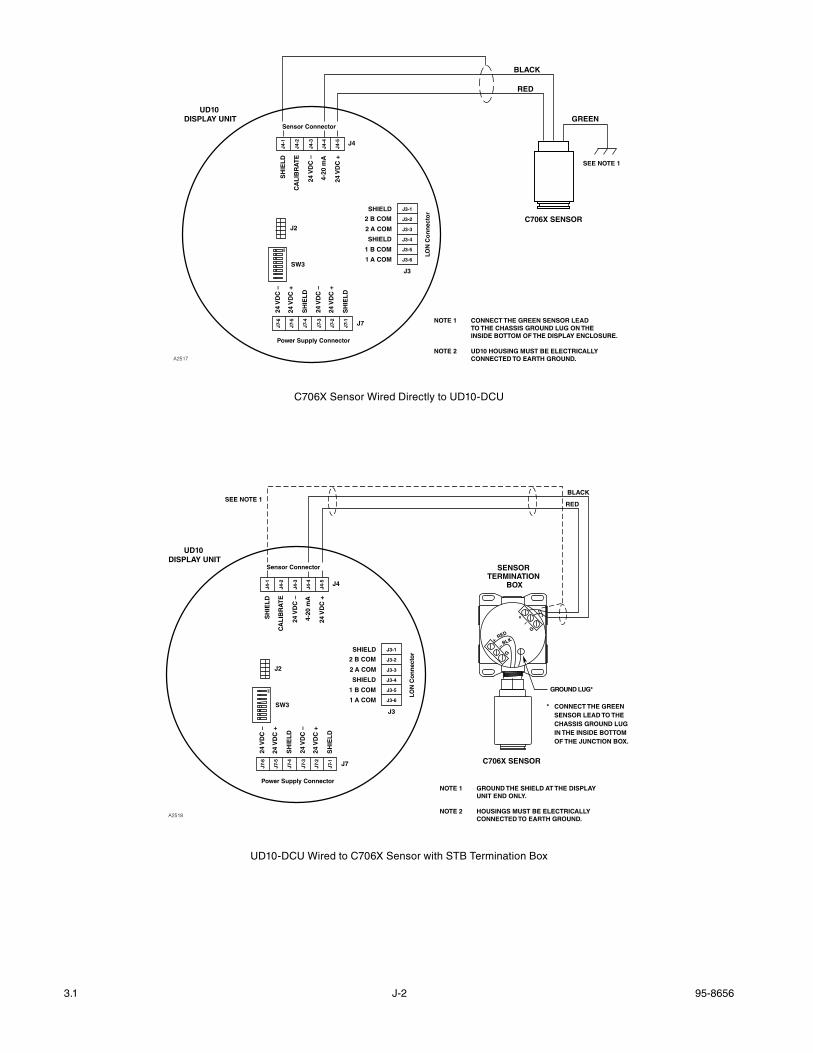
3.1 95-8656J-2
C706X SENSOR
BLACK
RED
GREEN
SEE NOTE 1
NOTE 1 CONNECT THE GREEN SENSOR LEAD TO THE CHASSIS GROUND LUG ON THE INSIDE BOTTOM OF THE DISPLAY ENCLOSURE.
NOTE 2 UD10 HOUSING MUST BE ELECTRICALLY CONNECTED TO EARTH GROUND.A2517
Sensor Connector
Power Supply Connector
LON
Co
nn
ecto
r
J4
J3
J7
24 V
DC
–
24 V
DC
+
SH
IEL
D
24 V
DC
–
24 V
DC
+
SH
IEL
D
SH
IEL
D
CA
LIB
RA
TE
24 V
DC
–
4-20
mA
24 V
DC
+
J4-1
J4-2
J4-3
J4-4
J4-5
J7-6
J7-5
J7-4
J7-3
J7-2
J7-1
SHIELD
2 B COM
2 A COM
SHIELD
1 B COM
1 A COM
J3-1
J3-2
J3-3
J3-4
J3-5
J3-6
UD10 DISPLAY UNIT
SW3
J2
ON
C706X Sensor Wired Directly to UD10-DCU
NOTE 1 GROUND THE SHIELD AT THE DISPLAY UNIT END ONLY.
NOTE 2 HOUSINGS MUST BE ELECTRICALLY CONNECTED TO EARTH GROUND.
SENSOR TERMINATION
BOX
SEE NOTE 1
A2518
RED
BLACK
* CONNECT THE GREEN SENSOR LEAD TO THE CHASSIS GROUND LUG IN THE INSIDE BOTTOM OF THE JUNCTION BOX.
C706X SENSOR
RED
BLK+
+
G
G
–
–
GROUND LUG*
Sensor Connector
Power Supply Connector
LON
Co
nn
ecto
r
J4
J3
J7
24 V
DC
–
24 V
DC
+
SH
IEL
D
24 V
DC
–
24 V
DC
+
SH
IEL
D
SH
IEL
D
CA
LIB
RA
TE
24 V
DC
–
4-20
mA
24 V
DC
+
J4-1
J4-2
J4-3
J4-4
J4-5
J7-6
J7-5
J7-4
J7-3
J7-2
J7-1
SHIELD
2 B COM
2 A COM
SHIELD
1 B COM
1 A COM
J3-1
J3-2
J3-3
J3-4
J3-5
J3-6
UD10 DISPLAY UNIT
SW3
J2
ON
UD10-DCU Wired to C706X Sensor with STB Termination Box
3.1 95-8656J-3
instAllAtion
wIRINg REQUIREmENTS
The simplest installation involves installing the sensor into one of the UD10-DCU openings and connecting the wiring directly to the UD10-DCU. If the installation requires separation of the C706x sensor and the UD10-DCU Display, the sensor can be connected to a STB sensor termination box, and the C706x/STB combination wired to the UD10-DCU. In this case, shielded cable is recommended to help protect against interference caused be extraneous electrical “noise.” In applications where the cable is installed in conduit, the conduit should not be used for wiring to other electrical equipment whenever possible. If other equipment power wiring is run in the same conduit, the cabling must be shielded. The maximum allowable distance between the C706x sensor and UD10-DCU Display Unit is limited by the resistance of the cabling used.
INSTaLLaTION aND wIRINg PROCEDURE
1. Determine the best mounting locations for the detectors.
2. Install the C706x sensor within the proper opening in the UD10-DCU or STB junction box. Mount the UD10-DCU/C706x with the sensor oriented vertically and the opening pointing down. The UD10-DCU should be electrically connected to earth ground.
noTeThe electrochemical sensor cell does not need to be installed within the C706X housing while installing and wiring the detector/junction box. It is recommended to keep the sensor in the manufacturer’s sealed shipping bag in a cool storage environment until actual power-up and calibration commissioning is performed. This will ensure that the sensor will provide maximum longevity.
3. Terminate all three C706x conductors at the proper terminals. Refer to the appropriate illustration for details.
4. Double check that all wiring is the proper size and type and has been installed correctly. Check operating voltage at the C706x sensor and the UD10-DCU Display Unit.
noTeDo not apply power to the system with the junction box cover removed unless the area has been de-classified.
5. Proceed with startup and calibration.
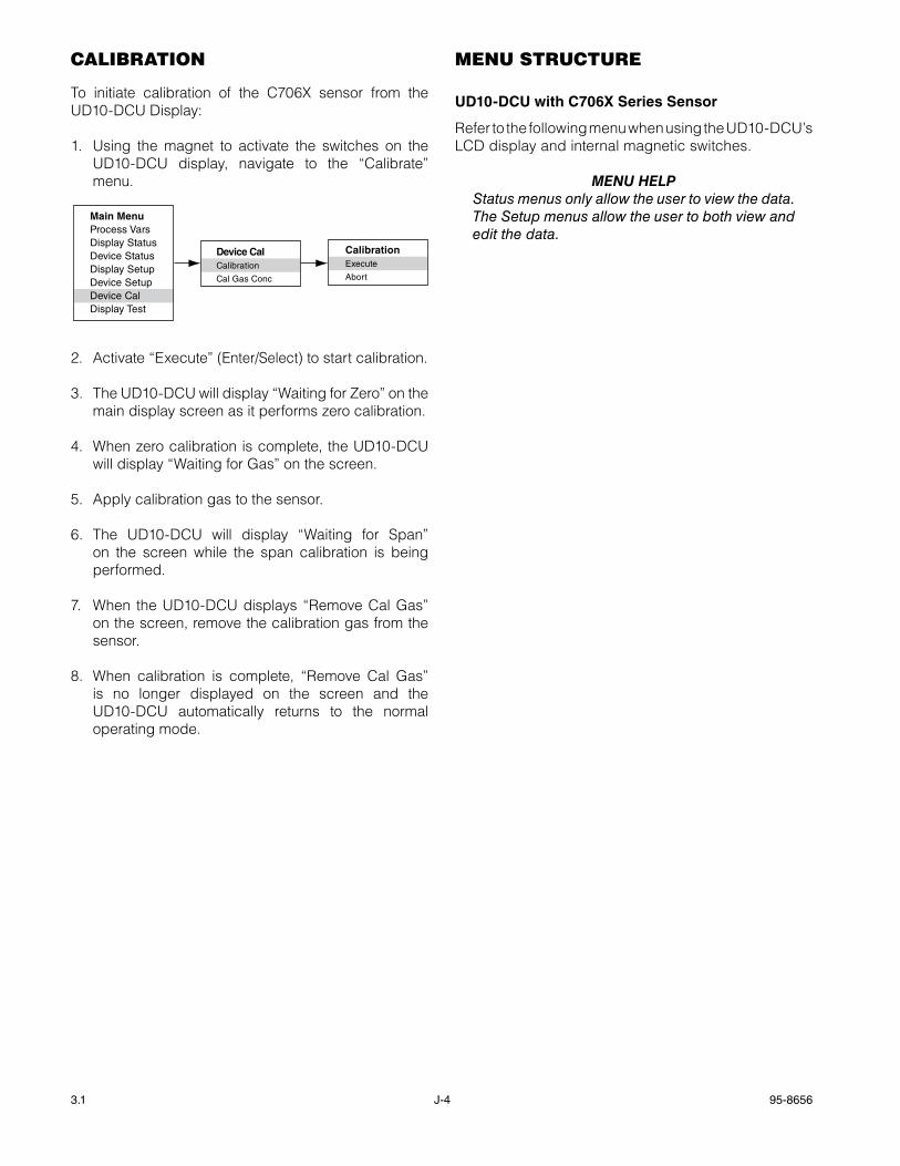
3.1 95-8656J-4
cAlibrAtion
To initiate calibration of the C706x sensor from the UD10-DCU Display:
1. Using the magnet to activate the switches on the UD10-DCU display, navigate to the “Calibrate” menu.
2. Activate “Execute” (Enter/Select) to start calibration.
3. The UD10-DCU will display “Waiting for Zero” on the main display screen as it performs zero calibration.
4. When zero calibration is complete, the UD10-DCU will display “Waiting for Gas” on the screen.
5. Apply calibration gas to the sensor.
6. The UD10-DCU will display “Waiting for Span” on the screen while the span calibration is being performed.
7. When the UD10-DCU displays “Remove Cal Gas” on the screen, remove the calibration gas from the sensor.
8. When calibration is complete, “Remove Cal Gas” is no longer displayed on the screen and the UD10-DCU automatically returns to the normal operating mode.
menu structure
UD10-DCU with C706x Series Sensor
Refer to the following menu when using the UD10-DCU’s LCD display and internal magnetic switches.
menu HeLpStatus menus only allow the user to view the data. The Setup menus allow the user to both view and edit the data.
Main MenuProcess VarsDisplay StatusDevice StatusDisplay SetupDevice SetupDevice CalDisplay Test
Device CalCalibration
Cal Gas Conc
CalibrationExecute
Abort
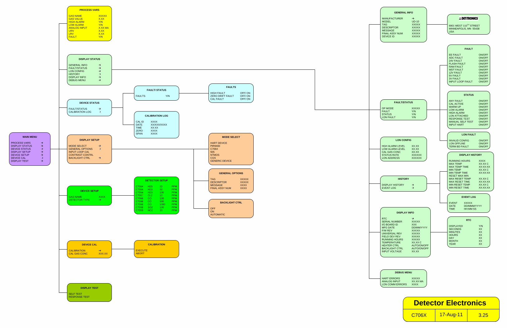
MAIN MENU
PROCESS VARSDISPLAY STATUSDEVICE STATUSDISPLAY SETUPDEVICE SETUPDEVICE CALDISPLAY TEST
PROCESS VARS
GAS NAME XXXXXGAS VALUE X.XXHIGH ALARM Y/NLOW ALARM Y/NANALOG INPUT X.XX MAURV X.XXLRV X.XXFAULT Y/N
DISPLAY STATUS
GENERAL INFOFAULT/STATUSLON CONFIGHISTORYDISPLAY INFODEBUG MENU
DISPLAY SETUP
MODE SELECTGENERAL OPTIONSINPUT LOOP CALCONTRAST CONTRLBACKLIGHT CTRL
DISPLAY TEST
SELF TESTRESPONSE TEST
FAULT/STATUS
OP MODE XXXXXFAULT Y/NSTATUS Y/NLON FAULT Y/N
GENERAL INFO
MANUFACTURERMODEL UD-10TAG XXXXXDESCRIPTOR XXXXXMESSAGE XXXXXFINAL ASSY NUM XXXXXDEVICE ID XXXXX
STATUS
ANY FAULT ON/OFFCAL ACTIVE ON/OFFWARM UP ON/OFFLOW ALARM ON/OFFHIGH ALARM ON/OFFLON ATTACHED ON/OFFRESPONSE TEST ON/OFFMANUAL SELF TEST ON/OFFINPUT HART ON/OFF
DEVICE STATUS
FAULT/STATUSCALIBRATION LOG
CALIBRATION LOG
CAL ID XXXXDATE XX/XXX/XXXXTIME XX:XXZERO XXXXSPAN XXXX
DEVICE SETUP
GAS NAME XXXXDETECTOR TYPE
DEVICE CAL
CALIBRATIONCAL GAS CONC XXX.XX
CALIBRATION
EXECUTEABORT
6901 WEST 110TH STREETMINNEAPOLIS, MN 55438USA
HISTORY
DISPLAY HISTORYEVENT LOG
DISPLAY INFO
RTCSERIAL NUMBER XXXXXI/O BOARD ID XXXMFG DATE DD/MM/YYYYF/W REV XXXXXUNIVERSAL REV XXXXXFIELD DEV REV XXXXXRUNNING HOURS XXXXXTEMPERATURE XX.XX CHEATER CTRL AUTO/ON/OFFBACKLIGHT CTRL AUTO/ON/OFFINPUT VOLTAGE XX.XX
EVENT LOG
EVENT XXXXXDATE DD/MMM/YYYYTIME HH:MM:SS
RTC
DISPLAYED Y/NSECONDS XXMINUTES XXHOURS XXDAY XXMONTH XXYEAR XX
DEBUG MENU
HART ERRORS XXXXXANALOG INPUT XX.XX MALON COMM ERRORS XXXX
FAULT
EE FAULT ON/OFFADC FAULT ON/OFF24V FAULT ON/OFFFLASH FAULT ON/OFFRAM FAULT ON/OFFWDT FAULT ON/OFF12V FAULT ON/OFF5V FAULT ON/OFF3V FAULT ON/OFFINPUT LOOP FAULT ON/OFF
FAULTS
HIGH FAULT OFF/ ONZERO DRIFT FAULT OFF/ ONCAL FAULT OFF/ ON
FAULT/ STATUS
FAULTS Y/N
MODE SELECT
HART DEVICEPIR9400C706X505NTMOSCGSGENERIC DEVICE
GENERAL OPTIONS
TAG XXXXXDESCRIPTOR XXXXXMESSAGE XXXXFINAL ASSY NUM XXXX
LON CONFIG
HGH ALARM LEVEL XX.XXLOW ALARM LEVEL XX.XXCAL GAS CONC XX.XXSTATUS RATE XXXXXXLON ADDRESS XXXXXX
DETECTOR SETUP
C7064 H2S 20 PPMC7064 H2S 50 PPMC7064 H2S 100 PPMC7067 CL2 10 PPMC7066 CO 100 PPMC7066 CO 500 PPMC7066 CO 1000 PPMC7068 SO2 100 PPMC7069 NO2 20 PPM
LON FAULT
INVALID CONFIG ON/OFFLON OFFLINE ON/OFFTERM BD FAULT ON/OFF
BACKLIGHT CTRL
OFFONAUTOMATIC
DISPLAY HISTORY
RUNNING HOURS XXXXMAX TEMP XX.XX CMAX TEMP TIME XX:XX:XXMIN TEMP XX.XX CMIN TEMP TIME XX:XX:XXRESET MAX MINMAX RESET TEMP XX.XX CMAX RESET TIME XX:XX:XXMIN RESET TEMP XX.XX CMIN RESET TIME XX:XX:XX
17-Aug-11C706X 3.25
Detector Electronics
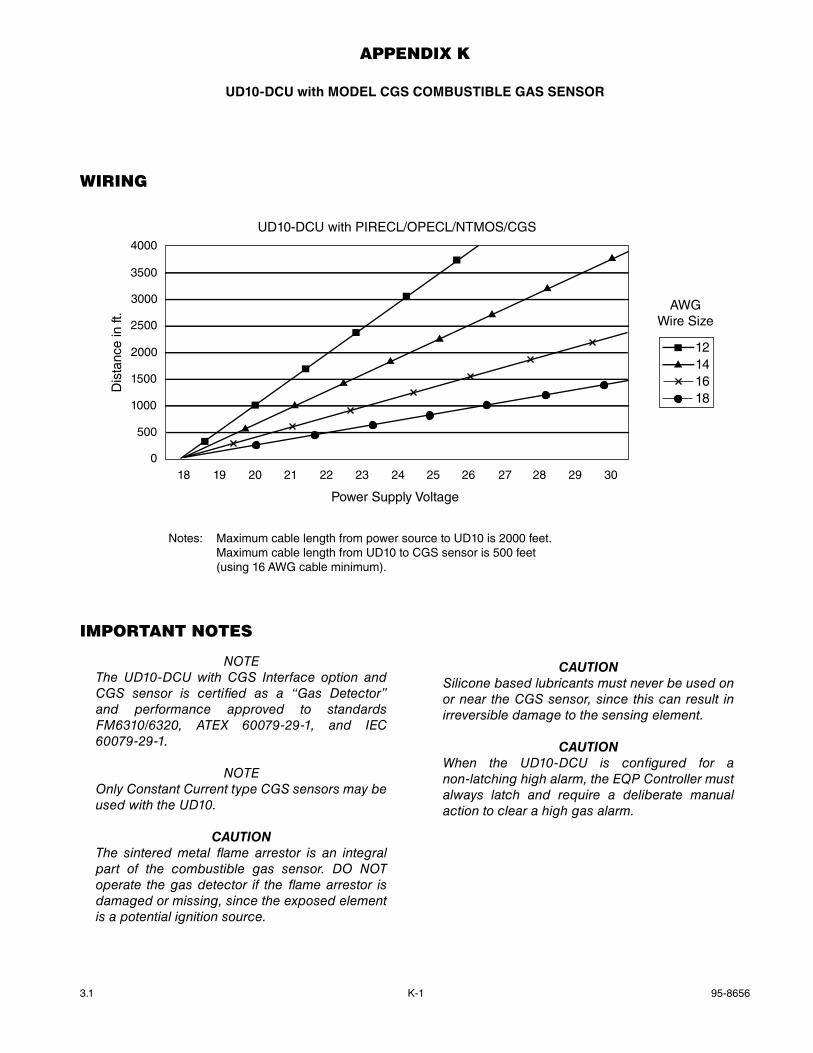
3.1 95-8656K-1
AppenDix K
UD10-DCU with mODEL CgS COmbUSTIbLE gaS SENSOR
WirinG
importAnt notes
noTeThe UD10-DCU with CGS Interface option and CGS sensor is certified as a “Gas Detector” and performance approved to standards FM6310/6320, ATeX 60079-29-1, and IeC 60079-29-1.
noTeonly Constant Current type CGS sensors may be used with the UD10.
CautIonThe sintered metal flame arrestor is an integral part of the combustible gas sensor. Do noT operate the gas detector if the flame arrestor is damaged or missing, since the exposed element is a potential ignition source.
CautIonSilicone based lubricants must never be used on or near the CGS sensor, since this can result in irreversible damage to the sensing element.
CautIonWhen the UD10-DCU is configured for a non-latching high alarm, the eQP Controller must always latch and require a deliberate manual action to clear a high gas alarm.
4000
3500
3000
2500
2000
1500
1000
500
018 19 20 21 22 23 24 25 26 27 28 29 30
Power Supply Voltage
Dis
tanc
e in
ft.
UD10-DCU with PIRECL/OPECL/NTMOS/CGS
12141618
AWGWire Size
Notes: Maximum cable length from power source to UD10 is 2000 feet. Maximum cable length from UD10 to CGS sensor is 500 feet (using 16 AWG cable minimum).
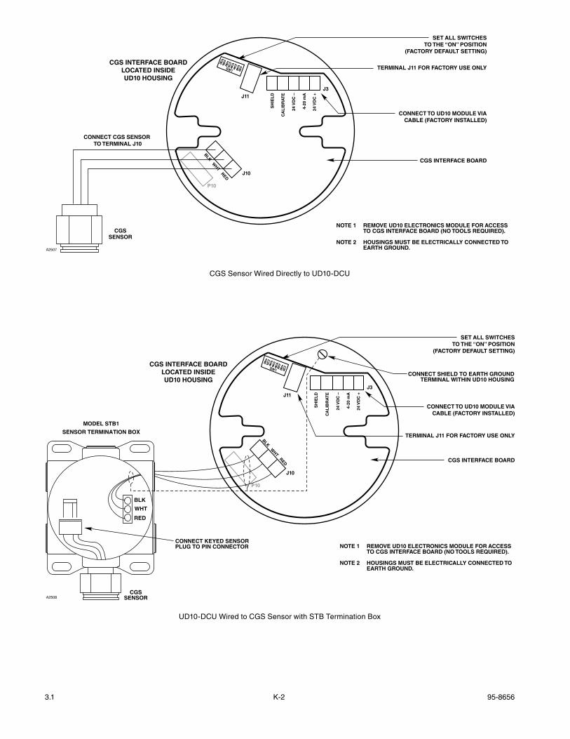
3.1 95-8656K-2
NOTE 1 REMOVE UD10 ELECTRONICS MODULE FOR ACCESS TO CGS INTERFACE BOARD (NO TOOLS REQUIRED).
NOTE 2 HOUSINGS MUST BE ELECTRICALLY CONNECTED TO EARTH GROUND.
CGS INTERFACE BOARDLOCATED INSIDEUD10 HOUSING
A2507
CONNECT TO UD10 MODULE VIACABLE (FACTORY INSTALLED)
CGS INTERFACE BOARD
CGSSENSOR
SW1
J3
BLKW
HTRED
P10
J10
J11
CONNECT CGS SENSOR TO TERMINAL J10
SET ALL SWITCHESTO THE “ON” POSITION
(FACTORY DEFAULT SETTING)
TERMINAL J11 FOR FACTORY USE ONLY
SH
IEL
D
CA
LIB
RA
TE
24 V
DC
–
4-20
mA
24 V
DC
+
CGS Sensor Wired Directly to UD10-DCU
NOTE 1 REMOVE UD10 ELECTRONICS MODULE FOR ACCESS TO CGS INTERFACE BOARD (NO TOOLS REQUIRED).
NOTE 2 HOUSINGS MUST BE ELECTRICALLY CONNECTED TO EARTH GROUND.
CGS INTERFACE BOARDLOCATED INSIDEUD10 HOUSING
A2508
CONNECT TO UD10 MODULE VIACABLE (FACTORY INSTALLED)
CGS INTERFACE BOARD
SW1
J3
BLKW
HTRED
P10
J10
J11
SET ALL SWITCHES TO THE “ON” POSITION
(FACTORY DEFAULT SETTING)
TERMINAL J11 FOR FACTORY USE ONLY
CONNECT KEYED SENSORPLUG TO PIN CONNECTOR
CONNECT SHIELD TO EARTH GROUNDTERMINAL WITHIN UD10 HOUSING
CGSSENSOR
BLK
WHT
RED
MODEL STB1
SENSOR TERMINATION BOX
SH
IEL
D
CA
LIB
RA
TE
24 V
DC
–
4-20
mA
24 V
DC
+
UD10-DCU Wired to CGS Sensor with STB Termination Box
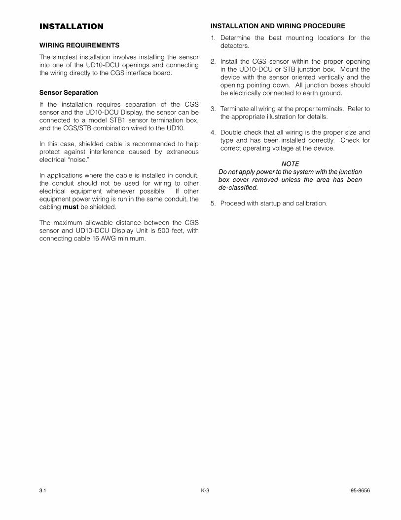
3.1 95-8656K-3
instAllAtion
wIRINg REQUIREmENTS
The simplest installation involves installing the sensor into one of the UD10-DCU openings and connecting the wiring directly to the CGS interface board.
Sensor Separation
If the installation requires separation of the CGS sensor and the UD10-DCU Display, the sensor can be connected to a model STB1 sensor termination box, and the CGS/STB combination wired to the UD10.
In this case, shielded cable is recommended to help protect against interference caused by extraneous electrical “noise.”
In applications where the cable is installed in conduit, the conduit should not be used for wiring to other electrical equipment whenever possible. If other equipment power wiring is run in the same conduit, the cabling must be shielded.
The maximum allowable distance between the CGS sensor and UD10-DCU Display Unit is 500 feet, with connecting cable 16 AWG minimum.
INSTaLLaTION aND wIRINg PROCEDURE
1. Determine the best mounting locations for the detectors.
2. Install the CGS sensor within the proper opening in the UD10-DCU or STB junction box. Mount the device with the sensor oriented vertically and the opening pointing down. All junction boxes should be electrically connected to earth ground.
3. Terminate all wiring at the proper terminals. Refer to the appropriate illustration for details.
4. Double check that all wiring is the proper size and type and has been installed correctly. Check for correct operating voltage at the device.
noTeDo not apply power to the system with the junction box cover removed unless the area has been de-classified.
5. Proceed with startup and calibration.
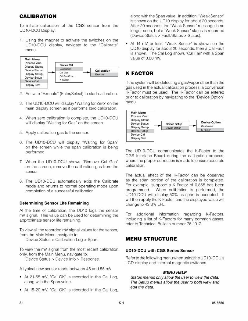
3.1 95-8656K-4
cAlibrAtion
To initiate calibration of the CGS sensor from the UD10-DCU Display:
1. Using the magnet to activate the switches on the UD10-DCU display, navigate to the “Calibrate” menu.
2. Activate “Execute” (Enter/Select) to start calibration.
3. The UD10-DCU will display “Waiting for Zero” on the main display screen as it performs zero calibration.
4. When zero calibration is complete, the UD10-DCU will display “Waiting for Gas” on the screen.
5. Apply calibration gas to the sensor.
6. The UD10-DCU will display “Waiting for Span” on the screen while the span calibration is being performed.
7. When the UD10-DCU shows “Remove Cal Gas” on the screen, remove the calibration gas from the sensor.
8. The UD10-DCU automatically exits the Calibrate mode and returns to normal operating mode upon completion of a successful calibration.
Determining Sensor Life Remaining
At the time of calibration, the UD10 logs the sensor mV signal. This value can be used for determining the approximate sensor life remaining.
To view all the recorded mV signal values for the sensor, from the Main Menu, navigate to: Device Status > Calibration Log > Span.
To view the mV signal from the most recent calibration only, from the Main Menu, navigate to: Device Status > Device Info > Response.
A typical new sensor reads between 45 and 55 mV.
• At21-55mV, "CalOK" is recorded in theCalLog,along with the Span value.
• At15-20mV, "CalOK" is recorded in theCalLog,
along with the Span value. In addition, "Weak Sensor" is shown on the UD10 display for about 20 seconds. After 20 seconds, the "Weak Sensor" message is no longer seen, but a "Weak Sensor" status is recorded (Device Status > Fault/Status > Status).
• At 14mV or less, "Weak Sensor" is shown on theUD10 display for about 20 seconds, then a Cal Fault is shown. The Cal Log shows "Cal Fail" with a Span value of 0.00 mV.
K fActor
If the system will be detecting a gas/vapor other than the gas used in the actual calibration process, a conversion K-Factor must be used. The K-Factor can be entered prior to calibration by navigating to the “Device Option” menu.
Main MenuProcess VarsDisplay StatusDevice StatusDisplay SetupDevice SetupDevice CalDisplay Test
Device SetupDevice Option
Device OptionGas Name
K-Factor
The UD10-DCU communicates the K-Factor to the CGS Interface Board during the calibration process, where the proper correction is made to ensure accurate calibration.
The actual effect of the K-Factor can be observed as the span portion of the calibration is completed. For example, suppose a K-Factor of 0.865 has been programmed. When calibration is performed, the UD10-DCU will display 50% as span is accepted. It will then apply the K-Factor, and the displayed value will change to 43.3% LFL.
For additional information regarding K-Factors, including a list of K-Factors for many common gases, refer to Technical Bulletin number 76-1017.
menu structure
UD10-DCU with CgS Series Sensor
Refer to the following menu when using the UD10-DCU’s LCD display and internal magnetic switches.
menu HeLpStatus menus only allow the user to view the data. The Setup menus allow the user to both view and edit the data.
Main MenuProcess VarsDisplay StatusDevice StatusDisplay SetupDevice SetupDevice CalDisplay Test
Device CalCalibration
Cal Gas
Cal Gas Conc
K Factor
CalibrationExecute
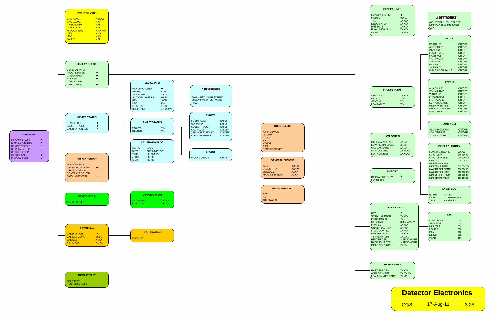
PROCESS VARS
GAS NAME XXXXXGAS VALUE X.XXHIGH ALARM Y/NLOW ALARM Y/NANALOG INPUT X.XX MAURV X.XXLRV X.XXFAULT Y/N
DISPLAY SETUP
MODE SELECTGENERAL OPTIONSINPUT LOOP CALCONTRAST CONTRLBACKLIGHT CTRL
HISTORY
DISPLAY HISTORYEVENT LOG
DISPLAY INFO
RTCSERIAL NUMBER XXXXXI/O BOARD ID XXXMFG DATE DD/MM/YYYYF/W REV XXXXXUNIVERSAL REV XXXXXFIELD DEV REV XXXXXRUNNING HOURS XXXXXTEMPERATURE XX.XX CHEATER CTRL AUTO/ON/OFFBACKLIGHT CTRL AUTO/ON/OFFINPUT VOLTAGE XX.XX
FAULT
EE FAULT ON/OFFADC FAULT ON/OFF24V FAULT ON/OFFFLASH FAULT ON/OFFRAM FAULT ON/OFFWDT FAULT ON/OFF12V FAULT ON/OFF5V FAULT ON/OFF3V FAULT ON/OFFINPUT LOOP FAULT ON/OFF
EVENT LOG
EVENT XXXXXDATE DD/MMM/YYYYTIME HH:MM:SS
RTC
DISPLAYED Y/NSECONDS XXMINUTES XXHOURS XXDAY XXMONTH XXYEAR XX
GENERAL OPTIONS
TAG XXXXXDESCRIPTOR XXXXXMESSAGE XXXXFINAL ASSY NUM XXXX
MODE SELECT
HART DEVICEPIR9400C706X505NTMOSCGSGENERIC DEVICE
DEVICE INFO
MANUFACTURERMODEL CGSGAS NAME XXXXXUNIT OF MEASURE %LFLURV 100%LRV 0%K-FACTOR XXXXRESPONSE XXXX MV
DEVICE STATUS
DEVICE INFOFAULT/ STATUSCALIBRATION LOG
CALIBRATION LOG
CAL ID XXXXDATE DD/MMM/YYYYTIME HH:MM:SSZERO XX.XXSPAN XX.XX
DEVICE SETUP
DEVICE OPTION
DEVICE OPTION
GAS NAME XXXXXK-FACTOR XXXXX
DEVICE CAL
CALIBRATIONCAL GAS CONC 50.00CAL GAS XXXXK FACTOR XX.XX
CALIBRATION
EXECUTE
STATUS
ANY FAULT ON/OFFCAL. ACTIVE ON/OFFWARM UP ON/OFFLOW ALARM ON/OFFHIGH ALARM ON/OFFLON ATTACHED ON/OFFRESPONSE TEST ON/OFFMANUAL SELF TEST ON/OFFINPUT HART ON/OFF
DISPLAY STATUS
GENERAL INFOFAULT/STATUSLON CONFIGHISTORYDISPLAY INFODEBUG MENU
FAULT/STATUS
OP MODE XXXXXFAULT Y/NSTATUS Y/NLON FAULT Y/N
6901 WEST 110TH STREETMINNEAPOLIS, MN 55438USA
DEBUG MENU
HART ERRORS XXXXXANALOG INPUT XX.XX MALON COMM ERRORS XXXX
GENERAL INFO
MANUFACTURERMODEL UD-10TAG XXXXXDESCRIPTOR XXXXXMESSAGE XXXXXFINAL ASSY NUM XXXXXDEVICE ID XXXXX
FAULTS
LOOP FAULT ON/OFFWARM UP ON/OFFSENSOR FAULT ON/OFFCAL FAULT ON/OFFZERO DRIFT FAULT ON/OFFCGS COMM FAULT ON/OFF
FAULT/ STATUS
FAULTS Y/NSTATUS Y/N
LON CONFIG
HGH ALARM LEVEL XX.XXLOW ALARM LEVEL XX.XXCAL GAS CONC XX.XXSTATUS RATE XXXXXXLON ADDRESS XXXXXX
6901 WEST 110TH STREETMINNEAPOLIS, MN 55438USA
DISPLAY TEST
SELF TESTRESPONSE TEST
STATUS
WEAK SENSOR ON/OFF
LON FAULT
INVALID CONFIG ON/OFFLON OFFLINE ON/OFFTERM BD FAULT ON/OFF
BACKLIGHT CTRL
OFFONAUTOMATIC
DISPLAY HISTORY
RUNNING HOURS XXXXMAX TEMP XX.XX CMAX TEMP TIME XX:XX:XXMIN TEMP XX.XX CRESET MAX MINMIN TEMP TIME XX:XX:XXMAX RESET TEMP XX.XX CMAX RESET TIME XX:XX:XXMIN RESET TEMP XX.XX CMIN RESET TIME XX:XX:XX
17-Aug-11CGS 3.25
Detector Electronics
MAIN MENU
PROCESS VARSDISPLAY STATUSDEVICE STATUSDISPLAY SETUPDEVICE SETUPDEVICE CALDISPLAY TEST
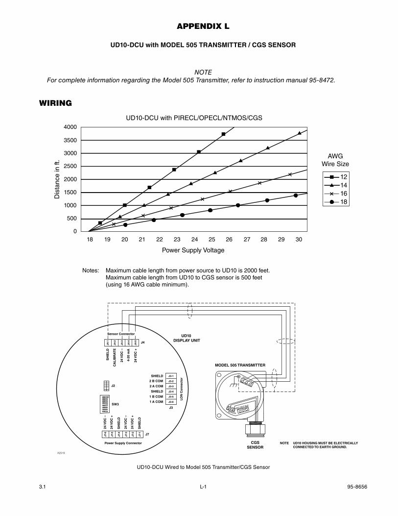
3.1 95-8656L-1
AppenDix l
UD10-DCU with mODEL 505 TRaNSmITTER / CgS SENSOR
noTeFor complete information regarding the Model 505 Transmitter, refer to instruction manual 95-8472.
WirinG
4000
3500
3000
2500
2000
1500
1000
500
018 19 20 21 22 23 24 25 26 27 28 29 30
Power Supply Voltage
Dis
tanc
e in
ft.
UD10-DCU with PIRECL/OPECL/NTMOS/CGS
12141618
AWGWire Size
Notes: Maximum cable length from power source to UD10 is 2000 feet. Maximum cable length from UD10 to CGS sensor is 500 feet (using 16 AWG cable minimum).
UD10 DISPLAY UNIT
MODEL 505 TRANSMITTER
CGSSENSOR
A2519
–SIG
RED
SENSOR
WHT BLK
+
NOTE UD10 HOUSING MUST BE ELECTRICALLY CONNECTED TO EARTH GROUND.
Sensor Connector
Power Supply Connector
LON
Co
nn
ecto
r
J4
J3
J7
24 V
DC
–
24 V
DC
+
SH
IEL
D
24 V
DC
–
24 V
DC
+
SH
IEL
D
SH
IEL
D
CA
LIB
RA
TE
24 V
DC
–
4-20
mA
24 V
DC
+
J4-1
J4-2
J4-3
J4-4
J4-5
J7-6
J7-5
J7-4
J7-3
J7-2
J7-1
SHIELD
2 B COM
2 A COM
SHIELD
1 B COM
1 A COM
J3-1
J3-2
J3-3
J3-4
J3-5
J3-6SW3
J2
ON
UD10-DCU Wired to Model 505 Transmitter/CGS Sensor
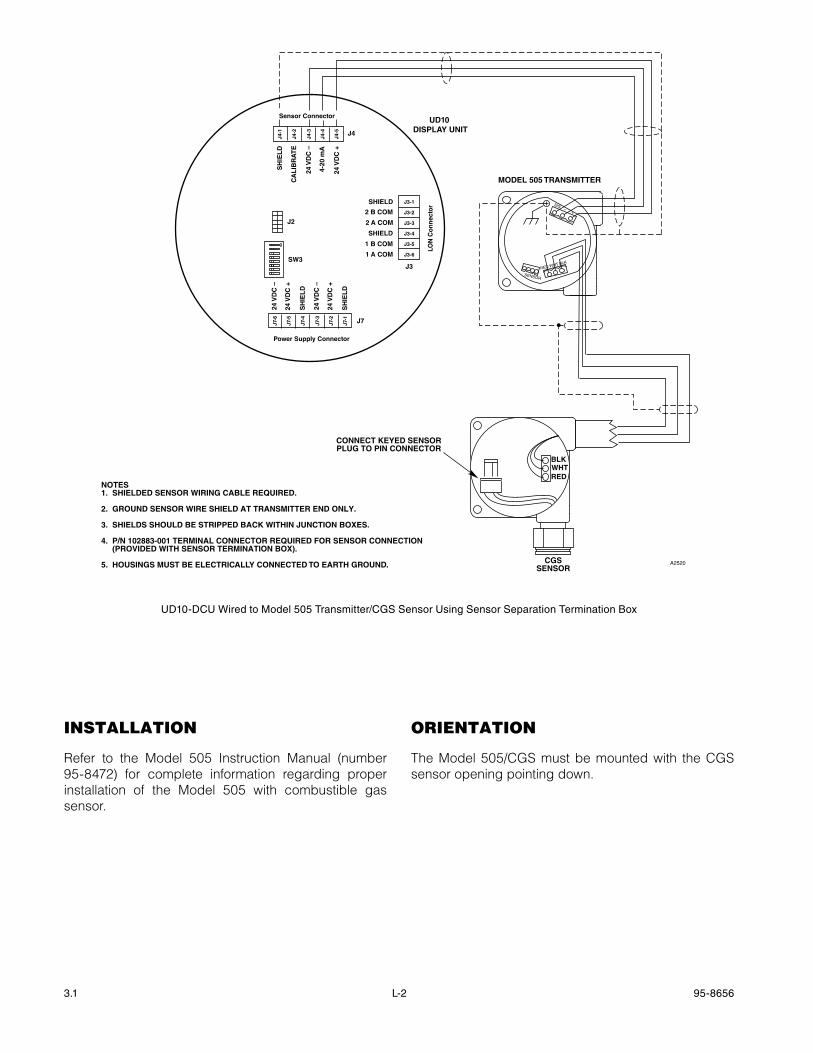
3.1 95-8656L-2
UD10 DISPLAY UNIT
MODEL 505 TRANSMITTER
A2520
–SIG
RED
SENSOR
WHT BLK
+
NOTES1. SHIELDED SENSOR WIRING CABLE REQUIRED.
2. GROUND SENSOR WIRE SHIELD AT TRANSMITTER END ONLY.
3. SHIELDS SHOULD BE STRIPPED BACK WITHIN JUNCTION BOXES.
4. P/N 102883-001 TERMINAL CONNECTOR REQUIRED FOR SENSOR CONNECTION 4. (PROVIDED WITH SENSOR TERMINATION BOX).
5. HOUSINGS MUST BE ELECTRICALLY CONNECTED TO EARTH GROUND. CGSSENSOR
CONNECT KEYED SENSORPLUG TO PIN CONNECTOR
BLKWHTRED
Sensor Connector
Power Supply Connector
LON
Co
nn
ecto
r
J4
J3
J7
24 V
DC
–
24 V
DC
+
SH
IEL
D
24 V
DC
–
24 V
DC
+
SH
IEL
D
SH
IEL
D
CA
LIB
RA
TE
24 V
DC
–
4-20
mA
24 V
DC
+
J4-1
J4-2
J4-3
J4-4
J4-5
J7-6
J7-5
J7-4
J7-3
J7-2
J7-1
SHIELD
2 B COM
2 A COM
SHIELD
1 B COM
1 A COM
J3-1
J3-2
J3-3
J3-4
J3-5
J3-6SW3
J2
ON
instAllAtion
Refer to the Model 505 Instruction Manual (number 95-8472) for complete information regarding proper installation of the Model 505 with combustible gas sensor.
orientAtion
The Model 505/CGS must be mounted with the CGS sensor opening pointing down.
UD10-DCU Wired to Model 505 Transmitter/CGS Sensor Using Sensor Separation Termination Box
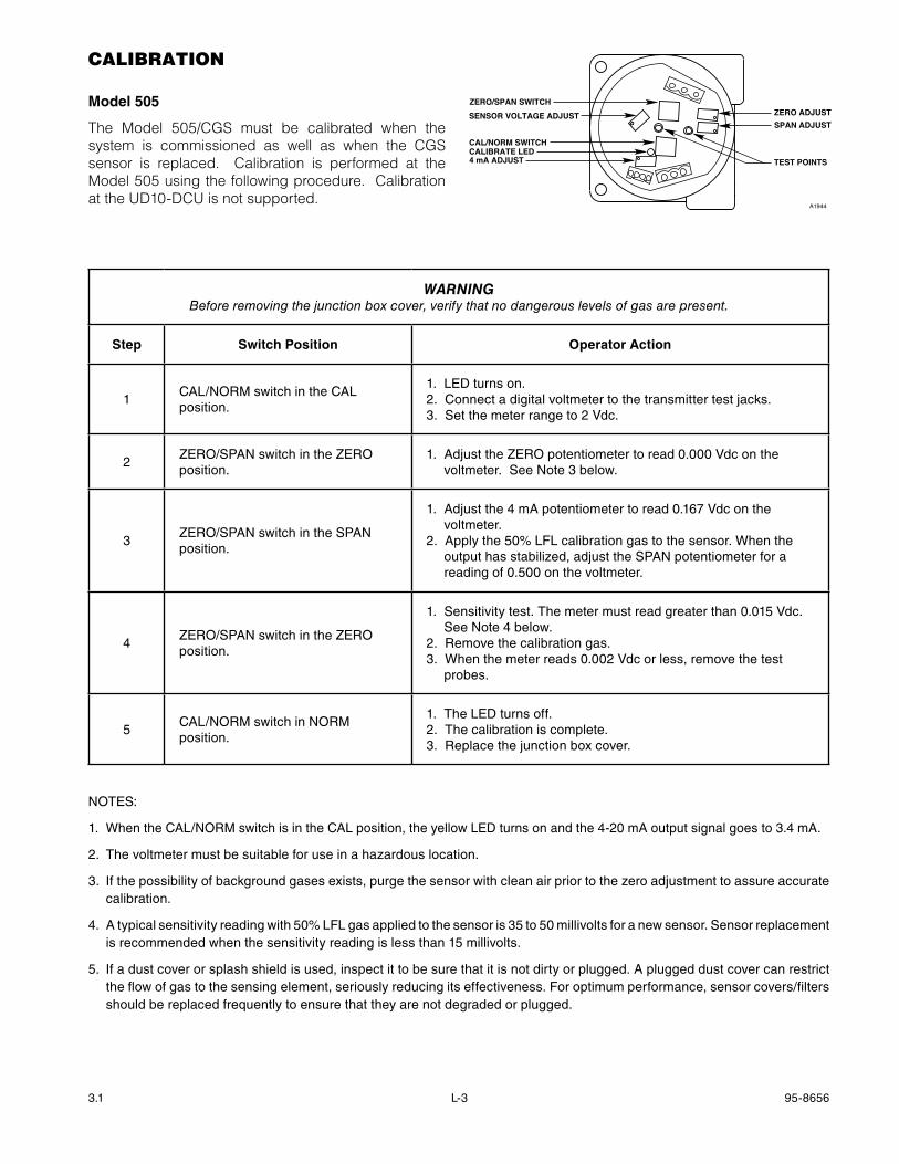
3.1 95-8656L-3
cAlibrAtion
model 505
The Model 505/CGS must be calibrated when the system is commissioned as well as when the CGS sensor is replaced. Calibration is performed at the Model 505 using the following procedure. Calibration at the UD10-DCU is not supported.
WarnIngBefore removing the junction box cover, verify that no dangerous levels of gas are present.
Step Switch Position Operator action
1CAL/NORM switch in the CAL position.
1. LED turns on. 2. Connect a digital voltmeter to the transmitter test jacks. 3. Set the meter range to 2 Vdc.
2ZERO/SPAN switch in the ZERO position.
1. Adjust the ZERO potentiometer to read 0.000 Vdc on the voltmeter. See Note 3 below.
3ZERO/SPAN switch in the SPAN position.
1. Adjust the 4 mA potentiometer to read 0.167 Vdc on the voltmeter.
2. Apply the 50% LFL calibration gas to the sensor. When the output has stabilized, adjust the SPAN potentiometer for a reading of 0.500 on the voltmeter.
4ZERO/SPAN switch in the ZERO position.
1. Sensitivity test. The meter must read greater than 0.015 Vdc. See Note 4 below.
2. Remove the calibration gas.3. When the meter reads 0.002 Vdc or less, remove the test
probes.
5CAL/NORM switch in NORM position.
1. The LED turns off.2. The calibration is complete.3. Replace the junction box cover.
NOTES:
1. When the CAL/NORM switch is in the CAL position, the yellow LED turns on and the 4-20 mA output signal goes to 3.4 mA.
2. The voltmeter must be suitable for use in a hazardous location.
3. If the possibility of background gases exists, purge the sensor with clean air prior to the zero adjustment to assure accurate calibration.
4. A typical sensitivity reading with 50% LFL gas applied to the sensor is 35 to 50 millivolts for a new sensor. Sensor replacement is recommended when the sensitivity reading is less than 15 millivolts.
5. If a dust cover or splash shield is used, inspect it to be sure that it is not dirty or plugged. A plugged dust cover can restrict the flow of gas to the sensing element, seriously reducing its effectiveness. For optimum performance, sensor covers/filters should be replaced frequently to ensure that they are not degraded or plugged.
ZERO ADJUSTZERO/SPAN SWITCHSENSOR VOLTAGE ADJUST
CAL/NORM SWITCHCALIBRATE LED4 mA ADJUST
SPAN ADJUST
TEST POINTS
A1944
3.1 95-8656L-4
menu structure
UD10-DCU with model 505 / CgS Sensor
Refer to the following menu when using the UD10-DCU’s LCD display and internal magnetic switches.
menu HeLpStatus menus only allow the user to view the data. The Setup menus allow the user to both view and edit the data.
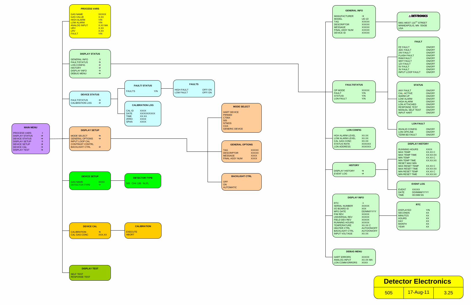
PROCESS VARS
GAS NAME XXXXXGAS VALUE X.XXHIGH ALARM Y/NLOW ALARM Y/NANALOG INPUT X.XX MAURV X.XXLRV X.XXFAULT Y/N
DISPLAY STATUS
GENERAL INFOFAULT/STATUSLON CONFIGHISTORYDISPLAY INFODEBUG MENU
DISPLAY SETUP
MODE SELECTGENERAL OPTIONSINPUT LOOP CALCONTRAST CONTRLBACKLIGHT CTRL
DISPLAY TEST
SELF TESTRESPONSE TEST
FAULT/STATUS
OP MODE XXXXXFAULT Y/NSTATUS\ Y/NLON FAULT Y/N
GENERAL INFO
MANUFACTURERMODEL UD-10TAG XXXXXDESCRIPTOR XXXXXMESSAGE XXXXXFINAL ASSY NUM XXXXXDEVICE ID XXXXX
STATUS
ANY FAULT ON/OFFCAL. ACTIVE ON/OFFWARM UP ON/OFFLOW ALARM ON/OFFHIGH ALARM ON/OFFLON ATTACHED ON/OFFRESPONSE TEST ON/OFFMANUAL SELF TEST ON/OFFINPUT HART ON/OFF
DEVICE STATUS
FAULT/STATUSCALIBRATION LOG
CALIBRATION LOG
CAL ID XXXXDATE XX/XXX/XXXXTIME XX:XXZERO XXXXSPAN XXXX
DEVICE SETUP
GAS NAME XXXXDETECTOR TYPE
DETECTOR TYPE
505 CH4 100 %LFL
DEVICE CAL
CALIBRATIONCAL GAS CONC XXX.XX
CALIBRATION
EXECUTEABORT
6901 WEST 110TH STREETMINNEAPOLIS, MN 55438USA
HISTORY
DISPLAY HISTORYEVENT LOG
DISPLAY INFO
RTCSERIAL NUMBER XXXXXI/O BOARD ID XXXMFG DATE DD/MM/YYYYF/W REV XXXXXUNIVERSAL REV XXXXXFIELD DEV REV XXXXXRUNNING HOURS XXXXXTEMPERATURE XX.XX CHEATER CTRL AUTO/ON/OFFBACKLIGHT CTRL AUTO/ON/OFFINPUT VOLTAGE XX.XX
EVENT LOG
EVENT XXXXXDATE DD/MMM/YYYYTIME HH:MM:SS
RTC
DISPLAYED Y/NSECONDS XXMINUTES XXHOURS XXDAY XXMONTH XXYEAR XX
DEBUG MENU
HART ERRORS XXXXXANALOG INPUT XX.XX MALON COMM ERRORS XXXX
FAULT
EE FAULT ON/OFFADC FAULT ON/OFF24V FAULT ON/OFFFLASH FAULT ON/OFFRAM FAULT ON/OFFWDT FAULT ON/OFF12V FAULT ON/OFF5V FAULT ON/OFF3V FAULT ON/OFFINPUT LOOP FAULT ON/OFF
FAULTS
HIGH FAULT OFF/ ON LOW FAULT OFF/ ON
FAULT/ STATUS
FAULTS Y/N
MODE SELECT
HART DEVICEPIR9400C706X505NTMOSCGSGENERIC DEVICE
GENERAL OPTIONS
TAG XXXXXDESCRIPTOR XXXXXMESSAGE XXXXFINAL ASSY NUM XXXX
LON CONFIG
HGH ALARM LEVEL XX.XXLOW ALARM LEVEL XX.XXCAL GAS CONC XX.XXSTATUS RATE XXXXXXLON ADDRESS XXXXXX
LON FAULT
INVALID CONFIG ON/OFFLON OFFLINE ON/OFFTERM BD FAULT ON/OFF
BACKLIGHT CTRL
OFFONAUTOMATIC
DISPLAY HISTORY
RUNNING HOURS XXXXMAX TEMP XX.XX CMAX TEMP TIME XX:XX:XXMIN TEMP XX.XX CMIN TEMP TIME XX:XX:XXRESET MAX MINMAX RESET TEMP XX.XX CMAX RESET TIME XX:XX:XXMIN RESET TEMP XX.XX CMIN RESET TIME XX:XX:XX
17-Aug-11505 3.25
Detector Electronics
MAIN MENU
PROCESS VARSDISPLAY STATUSDEVICE STATUSDISPLAY SETUPDEVICE SETUPDEVICE CALDISPLAY TEST
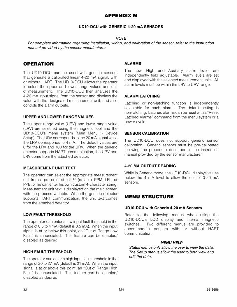
3.1 95-8656M-1
AppenDix m
UD10-DCU with gENERIC 4-20 ma SENSORS
noTeFor complete information regarding installation, wiring, and calibration of the sensor, refer to the instruction manual provided by the sensor manufacturer.
operAtion
The UD10-DCU can be used with generic sensors that generate a calibrated linear 4-20 mA signal, with or without HART. The UD10-DCU allows the operator to select the upper and lower range values and unit of measurement. The UD10-DCU then analyzes the 4-20 mA input signal from the sensor and displays the value with the designated measurement unit, and also controls the alarm outputs.
UPPER aND LOwER RaNgE vaLUES
The upper range value (URV) and lower range value (LRV) are selected using the magnetic tool and the UD10-DCU’s menu system (Main Menu > Device Setup). The URV corresponds to the 20 mA signal while the LRV corresponds to 4 mA. The default values are 0 for the LRV and 100 for the URV. When the generic detector supports HART communication, the URV and LRV come from the attached detector.
mEaSUREmENT UNIT TExT
The operator can select the appropriate measurement unit from a pre-entered list: % (default), PPM, LFL, or PPB, or he can enter his own custom 4-character string. Measurement unit text is displayed on the main screen with the process variable. When the generic detector supports HART communication, the unit text comes from the attached detector.
LOw FaULT ThREShOLD
The operator can enter a low input fault threshold in the range of 0.5 to 4 mA (default is 3.5 mA). When the input signal is at or below this point, an “Out of Range Low Fault” is annunciated. This feature can be enabled/disabled as desired.
hIgh FaULT ThREShOLD
The operator can enter a high input fault threshold in the range of 20 to 27 mA (default is 21 mA). When the input signal is at or above this point, an “Out of Range High Fault” is annunciated. This feature can be enabled/disabled as desired.
aLaRmS
The Low, High and Auxiliary alarm levels are independently field adjustable. Alarm levels are set and displayed with the selected measurement units. All alarm levels must be within the LRV to URV range.
aLaRm LaTChINg
Latching or non-latching function is independently selectable for each alarm. The default setting is non-latching. Latched alarms can be reset with a “Reset Latched Alarms” command from the menu system or a power cycle.
SENSOR CaLIbRaTION
The UD10-DCU does not support generic sensor calibration. Generic sensors must be pre-calibrated following the procedure described in the instruction manual provided by the sensor manufacturer.
4-20 ma OUTPUT REaDINg
While in Generic mode, the UD10-DCU displays values below the 4 mA level to allow the use of 0-20 mA sensors.
menu structure
UD10-DCU with generic 4-20 ma Sensors
Refer to the following menus when using the UD10-DCU’s LCD display and internal magnetic switches. Two different menus are provided to accommodate sensors with or without HART communication.
menu HeLpStatus menus only allow the user to view the data. The Setup menus allow the user to both view and edit the data.
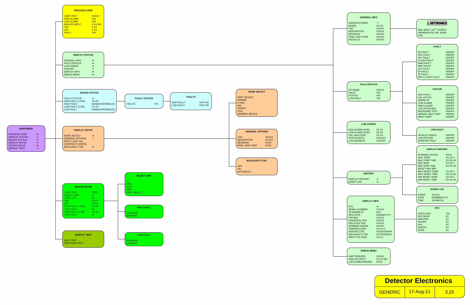
MAIN MENU
PROCESS VARSDISPLAY STATUSDEVICE STATUSDISPLAY SETUPDEVICE SETUPDISPLAY TEST
PROCESS VARS
USER TEXT XXXXXHIGH ALARM Y/NLOW ALARM Y/NANALOG INPUT X.XX MAURV X.XXLRV X.XXFAULT Y/N
DISPLAY STATUS
GENERAL INFOFAULT/STATUSLON CONFIGHISTORYDISPLAY INFODEBUG MENU
DISPLAY SETUP
MODE SELECTGENERAL OPTIONSINPUT LOOP CALCONTRAST CONTRLBACKLIGHT CTRL
DISPLAY TEST
SELF TESTRESPONSE TEST
FAULT/STATUS
OP MODE XXXXXFAULT Y/NSTATUS Y/NLON FAULT Y/N
GENERAL INFO
MANUFACTURERMODEL UD-10TAG XXXXXDESCRIPTOR XXXXXMESSAGE XXXXXFINAL ASSY NUM XXXXXDEVICE ID XXXXX
HISTORY
DISPLAY HISTORYEVENT LOG
DISPLAY INFO
RTCSERIAL NUMBER XXXXXI/O BOARD ID XXXMFG DATE DD/MM/YYYYF/W REV XXXXXUNIVERSAL REV XXXXXFIELD DEV REV XXXXXRUNNING HOURS XXXXXTEMPERATURE XX.XX CHEATER CTRL AUTO/ON/OFFBACKLIGHT CTRL AUTO/ON/OFFINPUT VOLTAGE XX.XX
FAULT
EE FAULT ON/OFFADC FAULT ON/OFF24V FAULT ON/OFFFLASH FAULT ON/OFFRAM FAULT ON/OFFWDT FAULT ON/OFF12V FAULT ON/OFF5V FAULT ON/OFF3V FAULT ON/OFFINPUT LOOP FAULT ON/OFF
STATUS
ANY FAULT ON/OFFCAL ACTIVE ON/OFFWARM UP ON/OFFLOW ALARM ON/OFFHIGH ALARM ON/OFFLON ATTACHED ON/OFFRESPONSE TEST ON/OFFMANUAL SELF TEST ON/OFFINPUT HART ON/OFF
EVENT LOG
EVENT XXXXXDATE DD/MMM/YYYYTIME HH:MM:SS
RTC
DISPLAYED Y/NSECONDS XXMINUTES XXHOURS XXDAY XXMONTH XXYEAR XX
MODE SELECT
HART DEVICEPIR9400C706X505NTMOSCGSGENERIC DEVICE
FAULTS
HIGH FAULT OFF/ ON LOW FAULT OFF/ ON
DEVICE STATUS
FAULT/ STATUSHIGH FAULT LEVEL XX.XXHIGH FAULT ENABLED/DISBALEDLOW FAULT LEVEL XX.XXLOW FAULT ENABLED/DISBALED
DEVICE SETUP
USER TEXT XXXXSELECT UNITUSER UNIT %URV XXXXLRV XXXXHIGH FAULT LEVEL XX.XXHIGH FAULTLOW FAULT LEVEL XX.XXLOW FAULT
DEBUG MENU
HART ERRORS XXXXXANALOG INPUT XX.XX MALON COMM ERRORS XXXX
SELECT UNIT
%PPM%LFLPPBUSER SELECT
6901 WEST 110TH STREETMINNEAPOLIS, MN 55438USA
FAULT/ STATUS
FAULTS Y/N
HIGH FAULT
DISABLEDENABLED
GENERAL OPTIONS
TAG XXXXXDESCRIPTOR XXXXXMESSAGE XXXXFINAL ASSY NUM XXXX
LOW FAULT
DISABLEDENABLED
LON CONFIG
HGH ALARM LEVEL XX.XXLOW ALARM LEVEL XX.XXCAL GAS CONC XX.XXSTATUS RATE XXXXXXLON ADDRESS XXXXXX
LON FAULT
INVALID CONFIG ON/OFFLON OFFLINE ON/OFFTERM BD FAULT ON/OFF
BACKLIGHT CTRL
OFFONAUTOMATIC
DISPLAY HISTORY
RUNNING HOURS XXXXMAX TEMP XX.XX CMAX TEMP TIME XX:XX:XXMIN TEMP XX.XX CMIN TEMP TIME XX:XX:XXRESET MAX MINMAX RESET TEMP XX.XX CMAX RESET TIME XX:XX:XXMIN RESET TEMP XX.XX CMIN RESET TIME XX:XX:XX
17-Aug-11GENERIC 3.25
Detector Electronics
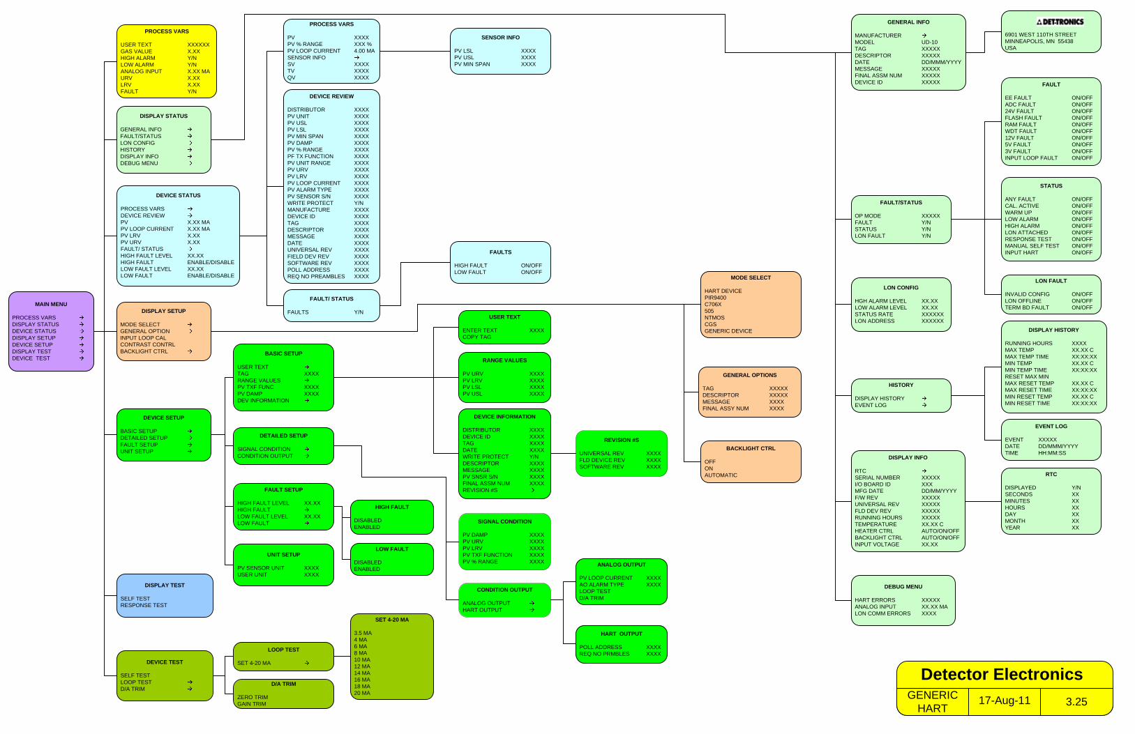
MAIN MENU
PROCESS VARSDISPLAY STATUSDEVICE STATUSDISPLAY SETUPDEVICE SETUPDISPLAY TESTDEVICE TEST
PROCESS VARS
USER TEXT XXXXXXGAS VALUE X.XXHIGH ALARM Y/NLOW ALARM Y/NANALOG INPUT X.XX MAURV X.XXLRV X.XXFAULT Y/N
DISPLAY STATUS
GENERAL INFOFAULT/STATUSLON CONFIGHISTORYDISPLAY INFODEBUG MENU
DISPLAY SETUP
MODE SELECTGENERAL OPTIONINPUT LOOP CALCONTRAST CONTRLBACKLIGHT CTRL
DISPLAY TEST
SELF TESTRESPONSE TEST
GENERAL INFO
MANUFACTURERMODEL UD-10TAG XXXXXDESCRIPTOR XXXXXDATE DD/MMM/YYYYMESSAGE XXXXXFINAL ASSM NUM XXXXXDEVICE ID XXXXX
HISTORY
DISPLAY HISTORYEVENT LOG
DISPLAY INFO
RTCSERIAL NUMBER XXXXXI/O BOARD ID XXXMFG DATE DD/MM/YYYYF/W REV XXXXXUNIVERSAL REV XXXXXFLD DEV REV XXXXXRUNNING HOURS XXXXXTEMPERATURE XX.XX CHEATER CTRL AUTO/ON/OFFBACKLIGHT CTRL AUTO/ON/OFFINPUT VOLTAGE XX.XX
EVENT LOG
EVENT XXXXXDATE DD/MMM/YYYYTIME HH:MM:SS
RTC
DISPLAYED Y/NSECONDS XXMINUTES XXHOURS XXDAY XXMONTH XXYEAR XX
GENERAL OPTIONS
TAG XXXXXDESCRIPTOR XXXXXMESSAGE XXXXFINAL ASSY NUM XXXX
MODE SELECT
HART DEVICEPIR9400C706X505NTMOSCGSGENERIC DEVICE
DEBUG MENU
HART ERRORS XXXXXANALOG INPUT XX.XX MALON COMM ERRORS XXXX
DEVICE TEST
SELF TESTLOOP TESTD/A TRIM
D/A TRIM
ZERO TRIMGAIN TRIM
LOOP TEST
SET 4-20 MA
SET 4-20 MA
3.5 MA4 MA6 MA8 MA10 MA12 MA14 MA16 MA18 MA20 MA
DEVICE SETUP
BASIC SETUPDETAILED SETUPFAULT SETUPUNIT SETUP
DETAILED SETUP
SIGNAL CONDITIONCONDITION OUTPUT
BASIC SETUP
USER TEXTTAG XXXXRANGE VALUESPV TXF FUNC XXXXPV DAMP XXXXDEV INFORMATION
SIGNAL CONDITION
PV DAMP XXXXPV URV XXXXPV LRV XXXXPV TXF FUNCTION XXXXPV % RANGE XXXX
DEVICE INFORMATION
DISTRIBUTOR XXXXDEVICE ID XXXXTAG XXXXDATE XXXXWRITE PROTECT Y/NDESCRIPTOR XXXXMESSAGE XXXXPV SNSR S/N XXXXFINAL ASSM NUM XXXXREVISION #S
CONDITION OUTPUT
ANALOG OUTPUTHART OUTPUT
RANGE VALUES
PV URV XXXXPV LRV XXXXPV LSL XXXXPV USL XXXX
ANALOG OUTPUT
PV LOOP CURRENT XXXXAO ALARM TYPE XXXXLOOP TESTD/A TRIM
HART OUTPUT
POLL ADDRESS XXXXREQ NO PRMBLES XXXX
REVISION #S
UNIVERSAL REV XXXXFLD DEVICE REV XXXXSOFTWARE REV XXXX
BACKLIGHT CTRL
OFFONAUTOMATIC
6901 WEST 110TH STREETMINNEAPOLIS, MN 55438USA
USER TEXT
ENTER TEXT XXXXCOPY TAG
FAULT SETUP
HIGH FAULT LEVEL XX.XXHIGH FAULTLOW FAULT LEVEL XX.XXLOW FAULT
UNIT SETUP
PV SENSOR UNIT XXXXUSER UNIT XXXX
HIGH FAULT
DISABLEDENABLED
LOW FAULT
DISABLEDENABLED
LON CONFIG
HGH ALARM LEVEL XX.XXLOW ALARM LEVEL XX.XXSTATUS RATE XXXXXXLON ADDRESS XXXXXX
FAULT
EE FAULT ON/OFFADC FAULT ON/OFF24V FAULT ON/OFFFLASH FAULT ON/OFFRAM FAULT ON/OFFWDT FAULT ON/OFF12V FAULT ON/OFF5V FAULT ON/OFF3V FAULT ON/OFFINPUT LOOP FAULT ON/OFF
STATUS
ANY FAULT ON/OFFCAL. ACTIVE ON/OFFWARM UP ON/OFFLOW ALARM ON/OFFHIGH ALARM ON/OFFLON ATTACHED ON/OFFRESPONSE TEST ON/OFFMANUAL SELF TEST ON/OFFINPUT HART ON/OFF
FAULT/STATUS
OP MODE XXXXXFAULT Y/NSTATUS Y/NLON FAULT Y/N
LON FAULT
INVALID CONFIG ON/OFFLON OFFLINE ON/OFFTERM BD FAULT ON/OFF
DEVICE STATUS
PROCESS VARSDEVICE REVIEWPV X.XX MAPV LOOP CURRENT X.XX MAPV LRV X.XXPV URV X.XXFAULT/ STATUSHIGH FAULT LEVEL XX.XXHIGH FAULT ENABLE/DISABLELOW FAULT LEVEL XX.XXLOW FAULT ENABLE/DISABLE
PROCESS VARS
PV XXXXPV % RANGE XXX %PV LOOP CURRENT 4.00 MASENSOR INFOSV XXXXTV XXXXQV XXXX
DEVICE REVIEW
DISTRIBUTOR XXXXPV UNIT XXXXPV USL XXXXPV LSL XXXXPV MIN SPAN XXXXPV DAMP XXXXPV % RANGE XXXXPF TX FUNCTION XXXXPV UNIT RANGE XXXXPV URV XXXXPV LRV XXXXPV LOOP CURRENT XXXXPV ALARM TYPE XXXXPV SENSOR S/N XXXXWRITE PROTECT Y/NMANUFACTURE XXXXDEVICE ID XXXXTAG XXXXDESCRIPTOR XXXXMESSAGE XXXXDATE XXXXUNIVERSAL REV XXXXFIELD DEV REV XXXXSOFTWARE REV XXXXPOLL ADDRESS XXXXREQ NO PREAMBLES XXXX
FAULTS
HIGH FAULT ON/OFFLOW FAULT ON/OFF
FAULT/ STATUS
FAULTS Y/N
SENSOR INFO
PV LSL XXXXPV USL XXXXPV MIN SPAN XXXX
DISPLAY HISTORY
RUNNING HOURS XXXXMAX TEMP XX.XX CMAX TEMP TIME XX:XX:XXMIN TEMP XX.XX CMIN TEMP TIME XX:XX:XXRESET MAX MINMAX RESET TEMP XX.XX CMAX RESET TIME XX:XX:XXMIN RESET TEMP XX.XX CMIN RESET TIME XX:XX:XX
17-Aug-11GENERIC HART 3.25
Detector Electronics
Detector Electronics Corporation6901 West 110th Street
Minneapolis, MN 55438 USA
T: 952.941.5665 or 800.765.3473F: 952.829.8750
W: http://www.det-tronics.comE: [email protected]
Det-Tronics, the DET-TRONICS logo, Eagle Quantum Premier, Eclipse, and FlexVu are registered trademarks or trademarks of Detector Electronics Corporation in the United States, other countries, or both. Other company, product, or service names may be trademarks or service marks of others.
© Copyright Detector Electronics Corporation 2011. All rights reserved.
X3301 Multispectrum IR Flame Detector
PointWatch Eclipse® IR Combustible Gas Detector
Eagle Quantum Premier® Safety System
FlexVu® Universal Displayw/ GT3000 Toxic Gas Detector
95-8656