Embed Size (px)
Citation preview

Page 1
INSTRUCTIONSAND
PARTS LIST
SINGLE GIRDERUNDERHUNG CRANE
BRIDGE KITS
HAND GEAREDAND
MOTOR DRIVEN
July, 2003 Copyright 2003, Yale•Lift-Tech, division of Columbus McKinnon Corporation Part No. 113533-93
Follow all instructions and warnings while installing or operating this crane bridge. The installationor operation of any crane bridge presents some risk of personal injury or property damage if properinstructions and warnings are not followed. Before installing or operating this crane bridge theoperator should become thoroughly familiar with all warnings, instructions and recommendations inthis manual.
Retain this manual for future reference & use.

Page 2
INSTALLING CRANE BRIDGE
Only a qualified crane installer shall perform the installationof the crane on the runway.
For information regarding attaching, lifting and moving theloads during installation refer to ANSI B30.11-latest edition,Chapter 11-3 and other applicable codes.
Prior to the start of any crane erection the building should bemeasured for span and clearances. These measurementsshould be checked against the corresponding cranemeasurements to insure correctness of "fit". After assurancesthat the crane fits the building, determine orientation ofcrane with respect to the runway.
These types of cranes are usually lifted into position on therunway beams in one piece. Total weight of this crane shouldbe checked against lifting equipment selected for erection ofthis crane.
Immediately after the crane is placed on the runway beamscheck the wheel flange clearances to the runway beam. SeeFigure 1. Encroachment of flange connections may causeinterference.
1. Open End Runway. If one end of the crane runway isopen and no interference is encountered the crane bridgecan be placed on the end of the runway. First recheck thedistance between the wheels. The distance between the
FOREWORDThis manual contains important information to help youinstall, operate, maintain and service your new single girderunder running bridge. We recommend that you study itscontents thoroughly before putting the crane bridge intouse. With proper installation, application of correct operatingprocedures, and practicing the recommended maintenanceactions you will be assured of the maximum service fromyour crane bridge.
The crane bridges described in this manual are intended forindoor service. Bridges to be used for outdoor servicerequire special considerations.
IMPORTANT!
When ordering replacement parts, be sure to include withyour order the CATALOG and KEY NUMBERS, which areidentified elsewhere in this manual.
Information given in this manual is subject to change withoutnotice.
GENERAL DESCRIPTIONGENERAL - These under running crane bridges are designedto operate on parallel American Standard or Wide Flangecrane runway beams. Motors and controls are designed for230V, 460V or 575V, 3 phase, 60 hertz power supply. Thebridge is equipped with single, two or variable speed motorscontrolled from a pendant push button station. The pushbutton may be located on the bridge or hoist trolley unit.Under running single girder crane bridges described hereinare built in capacities from 1 through 10 tonnes with spansthrough 60'-0".
BASIC CONSTRUCTION
The basic construction of single girder under running bridgesconsists of American Standard or Wide Flange beam girdersrigidly connected to the bottom and side of each end truck.Each truck has driver wheels and trailer wheels, which runon the runway beams. The wheels are mounted on fixedaxles and rotate on anti-friction bearings.
These bridges are driven by a motor and gear case attachedto each end truck. The motor drives a single wheel at eachend truck through the gear case then through a drive pinionand geared wheel arrangement.
INSTALLATIONGENERAL - Runway beams on which these cranes willoperate must be sufficiently strong enough to support cranebridge, hoisting equipment and rated load. Runway beamsmust be in accordance with CMAA 74-latest edition Table1.4.1-1 and the lower flange track wheel surface must befree of distortion or imperfections that may cause amalfunction or damage to the crane wheels.
The maximum gap between mating ends of runway beamsections must not exceed 1/16". Figure 1.
Working in or near exposed energized electricalequipment presents the danger of electric shock.
TO AVOID INJURY:
Disconnect power and lockout/tagout disconnectingmeans before installing crane or runway.
WARNING

Page 3
RUNWAY CONDUCTORS
Motorized crane bridges and crane bridges equipped with amotorized trolley or hoist require runway conductors. Installconductors according to manufacturer's instructions and inaccordance with National, State and Local codes. Refer alsoto article 6.10 of N.E.C.
Install, adjust and align collectors with runway conductors.Connect collectors to appropriate crane wiring as shown in113533-83, Wiring Diagrams for Bridge Control Panels.
CROSS CONDUCTORS
In most cases, the cross conductors will be installed on yourcrane as received; however, if the conductors have beenseparately shipped, be certain that the instructions coveringinstallation of these conductors are carefully followed.Connect all wiring on the crane (main collectors to bridgepanel, bridge panel to cross conductors, bridge panel tobridge motor) in accordance with the appropriate cranewiring diagram shown in 113533-83, Wiring Diagrams forBridge Control Panels.
TROLLEY COLLECTORS
Electrically operated hoists and/or trolleys require trolleycollectors. Install collectors as shown in instructions furnishedwith the hoist and trolley. Connect wiring as shown on theappropriate crane wiring diagram.
PRE-OPERATION CHECKS
After the crane has been installed on the runway and thecrane and hoist/trolley unit connected to electrical service,the following pre-operation checks should be made beforeoperation:
inside faces of the wheel flanges should be the width of thebottom flange of the runway beam plus 1/4". See Figure 1.Note also that the dimensions from the flanges of therunway to the side of the truck should be equal as shown inFigure 1. If all dimensions are correct, lift the crane bridgeso that the wheels are level with the contact surface on therunway beam. Carefully move the crane bridge onto therunway.
2. Removable Runway Section. In some installations aremovable section of runway may be available. If so removerunway section, install crane bridge as in paragraph 1 andreinstall runway section.
3. Truck Side Removal. If the methods previously describedare not possible, one half of each truck must be removed.The trucks should already have been adjusted for the properrunway width, as in "Assembling the End Trucks".Disassemble the outside half of one truck and the inside halfof the other truck. Retain all bolts, lock washers, cross shaftand other parts that need to be removed. Lift the cranebridge with the truck halves attached into place and carefullywork onto the runway. Reassemble the truck halves with theproper bolts, lock washers, and cross shaft parts. Tightenthe spacer block connections per Section 8.d.1 of the AISC"Specifications for Structural Joints using ASTM A325 or490 Bolts" : tighten snug tight, then make 1/3 more turn.
Note: It is suggested that the trolley and hoist beinstalled on the crane bridge at this time so that allwiring connections can be completed.
CONNECTING BRIDGE TO ELECTRICAL SERVICECrane panel wiring diagrams are shown in Part No.113533-83, Wiring Diagrams for Bridge Control Panels.
For a crane bridge mounted on a runway beam, theomission of end stops can result in loss of crane bridgewith resultant injury or damage.
TO AVOID INJURY OR DAMAGE:
Install end stops to prevent the crane from running offthe end of the beam.
WARNING
End trucks not properly equipped with supplied safetydrop lugs and high strength bolts can result in loss ofcrane bridge with resultant injury and damage
TO AVOID INJURY OR DAMAGE:
Be certain that prior to crane use the safety lugs arefirmly bolted in place using the supplied high strengthbolts.
WARNING
Improper power supply can damage electricalcomponents
TO AVOID DAMAGE:
Power supply must be the same voltage, frequency andphase as runway power supply. Crane voltage is shownon the nameplate on the bridge panel.
Do not operate crane until "Pre-Operation Checks"below are made.
WARNING
Working in or near exposed electrical equipmentpresents the danger of electric shock.
TO AVOID INJURY:
Before attempting any electrical connections, the mainpower switch feeding the runway must be locked in theopen (off) position.
WARNING

Page 4
1. Check the main collector system for proper adjustment tomaintain proper contact with conductors. Check along runwayfor possible interference if power is cable reel or festoonedcable.
2. Check cross conductors and collectors for adjustment andproper tracking.
3. Check gearing at wheels and the oil level of the gear case.If lubricant is required see LUBRICATION underMAINTENANCE. Make sure that the vent is installed in thegear case and is at the highest possible level.
4. Inspect crane to make certain that all bolted connectionsand attachments are properly tightened and that all electricalconnections are secure.
5. Read the brake literature and check brake adjustmentand electrical connections.
6. The hoist/trolley unit should be checked as instructed inthe Hoist Manufacturer's Instruction Manual. Check to makesure that the trolley wheels have the proper clearance to thebeam (girder) flange for freedom of operation. Make certaintrolley stops have been installed and that they are correctlylocated.
7. All trolley and bridge wheels as well as the flange surfacesof the bridge and runway beams on which the wheels rollmust be free of paint to provide the proper electrical ground.If the environment in which the crane will operate is such asto impair the contact between the wheels and the beamflanges, extra cross conductors and collectors must beprovided for grounding purposes.
OPERATIONOPERATOR QUALIFICATIONS - Safe and efficient craneoperation requires skill, extreme care and good judgment,alertness, concentration, knowledge of and rigid adherenceto proven safety rules and practices. No person should bepermitted to operate a crane or hoist:
1. who does not possess the above characteristics.
2. who is not qualified or has handicaps that could adverselyaffect such operation.
3. who has not been properly instructed.
4. who has not been informed and does not have a thoroughknowledge of all applicable safe operating practices, including
those in this book as well as of rigging equipment andpractices.
Note: See applicable National, State and Local SafetyCodes and regulations for additional requirementsrelating to Safe Operating Practices, including ANSIB30.11 - latest edition.
Prior to placing the crane into service, OSHA requires thatthe user performs and records certain tests including proofloading of the crane. Refer to ANSI B30.11 for informationabout these requirements.
OPERATING RULES
Operating rules listed below are an earnest effort toencourage SAFETY and are not intended to take precedenceover individual plant safety rules and regulations or rules setforth by various applicable codes.
A good operator operates his crane as smoothly as possibleand knows and follows the suggested rules below for safe,efficient crane handling.
OPERATING PRECAUTIONS
Safe operation of an overhead hoist is the operator'sresponsibility. Listed below are some basic rules that canmake an operator aware of dangerous practices to avoidand precautions to take for his own safety and the safety ofothers. Observance of these rules in addition to frequentexaminations and periodic inspection of the equipment maysave injury to personnel and damage to the equipment.
DO NOT load bridge beyond rated capacity.
DO NOT subject bridge to side loads. Always center trolleyover load when hoisting.
DO NOT stand and DO NOT cause or allow others to standor get under any load the bridge is supporting.
DO keep clear, and make sure others keep clear, of any loadthe bridge is supporting.
DO NOT attempt to operate crane bridge before completingtests and adjustments.
DO NOT run bridge into end stops, other bridge, or anyobstruction on beam. Improper and careless operation canresult in a hazardous condition for operator and load.
ALWAYS be sure load is clear of obstruction before traversingload.
The omission or incorrect location of trolley stops canresult in loss of hoist trolley with resultant injury anddamage.
TO AVOID INJURY AND DAMAGE:
Install end stops per the Trolley Stop Table on the BridgeAssembly Drawings to prevent the hoist trolley fromrunning off the end of the beam.
WARNINGSupporting or transporting people or transporting loadsover people can result in injury.
TO AVOID INJURY:
DO NOT USE These crane bridges for support ortransport of people or for transporting loads overpeople.
WARNING

Page 5
If crane bridge is mounted on an open-end runway rail, thenend stops must be installed to prevent crane bridge fromrunning off the end of the runway rail resulting in injury to theoperator and others and damages to the load and otherproperty. End stops for the trolley must also be installed.
Refer to hoist and trolley instruction manuals for safetywarnings on hoists and trolleys.
Read and comply with ANSI\ASME B30.11 - latest edition.Read and comply with all local, state and national safetycodes.
GENERAL
Motor driven cranes are operated from a pendant pushbutton station. The push button may be suspended from thebridge, trolley or hoist. Push button control stations, supportedby a strain cable, have a built-in interlock to prevent energizingopposing motions at the same time.
LEARNING THE CONTROLS
After making certain the crane is completely and properlyinstalled, with the crane connected to the electrical serviceand all the pre-operation checks made, the operator shouldlearn the controls.
On cranes having any or all motions electrically operated,the operator should locate the runway disconnect and makesure this switch is locked open (POWER OFF). The operatorshould now operate the various push buttons to get the"feel" and determine that they do not bind or stick in anyposition. The operator should become familiar with pushbutton location for their respective motions as well as "start"and "stop" buttons (normally the top two buttons), whichoperate the crane main line contactor. The main line contactorwill shut off power to all motions.
OPERATING THE CONTROLS (NO LOAD)
Having inspected and tried the control, the crane operator isnow ready to try the crane under power.
Step 1. - Close the crane runway disconnect switch.
Step 2. - Close the crane disconnect switch mounted on thecrane. The crane main disconnect switch is located in thebridge panel and is operable from the front of the panelwithout opening the panel. Rotating the handle operates theswitch. The "OFF" and "ON" positions of the switch aremarked on the switch assembly.
The bridge control panel also contains a 3-pole mainlinecontactor. This contactor is connected in the electricalsystem on the load side of the crane main disconnectswitch, so that all the crane power flows through thiscontactor. The mainline contactor is opened and closed(turned off and on) by means of the stop-start buttons on thependant push button station. This stop-start circuit, as wellas other control circuits, operates at 115 volts. This 115-voltcontrol circuit voltage is obtained from a transformer mountedin the bridge control panel.
Step 3. - Press the start push button, which will close themainline contactor, applying power to all control devices.The crane is now ready for further testing.
When the bridge on this crane is powered by two- speedmotors the slow speed is used for starting and for positioning.The fast speed is used for general bridge movement betweentwo points. There is one button for each direction labeledbridge "FWD" and "REV". Depressing either button slightlywill cause the bridge to operate at slow speed. Furtherdepression of the button will cause the bridge to run at fastspeed.
Step 4. - Momentarily depress bridge "FWD" button. Checkto be certain both motors run in the same direction.Momentarily depress "REV" button. Motors running in theopposite direction will cause vibration and skewing of thebridge.
Step 5. - To check that electrical connections have beenproperly made, operate bridge cautiously on runway. Watchfor any obstructions or interference between crane andbuilding part. Depress "FWD" button slightly - bridge willtravel along runway without vibration or skewing when bothmotors are running at the same speed. If skewing is evident,stop bridge and recheck motor electrical connections.
Injury to personnel or damage to equipment may resultif all installation and operation checks are not done inaccordance with instructions.
TO AVOID INJURY OR DAMAGE:
Make sure all INSTALLATION AND OPERATIONCHECKS have been made in accordance withinstructions furnished with the HOIST and TROLLEYbefore turning on the power.
WARNING
Damage to personnel or equipment may occur if poweris turned on when pushbutton binds or sticks in anyposition.
TO AVOID INJURY OR DAMAGE:
DO NOT turn power on. Determine the cause ofmalfunction and correct it before operating the crane.
WARNING
ABRUPT CHANGE OF BRIDGE DIRECTION WHILE INMOTION MAY CAUSE ADVERSE OPERATINGCHARACTERISTICS OR DAMAGE TO BRIDGE ANDDRIVE COMPONENTS.
TO AVOID DAMAGE:
Always allow the crane to come to a complete stopbefore changing directions.
WARNING
Page 6
Step 6. - Operate bridge from one end of the runway to theother checking for obstructions or interference. Proceedwith CAUTION and be prepared to stop short of anyobstructions. If bridge power is interrupted during runwaytravel, check main collectors for proper contact with runwayconductors.
Step 7. - After making certain that all building and structuralclearances are adequate, practice going "FWD" and "REV"with push button depressed only slightly (slow speed). Notethe stopping distance of the bridge at slow speed withoutload. Now depress "FWD" or "REV" farther, causing thecrane to run at faster speed. Again note the distance thecrane requires to stop after releasing the push button.
The above checkout procedure may be used for the trolleynoting some minor differences:
The trolley push button is labeled "LEFT" and "RIGHT".
Note: Since a variety of hoist/trolley combinations maybe used on this type of bridge, consult theManufacturer's Instructions to familiarize yourself withthat equipment.Refer also to ANSI/ASME B30.16.
After becoming familiar with these motions, the operatorcan now depress the hoist "UP" button.
Depress the "DOWN" button. Practice moving the hook upand down.
The hook may be lowered until TWO FULL WRAPS of cableremain on the drum. Note the position of the hook andNEVER LOWER THE HOOK BELOW THIS POSITION.Some hoists may have a lower limit switch that will stop thehoist when this position is reached. Consult the HoistManufacturer's Manual.
Depress the hoist "UP" button and slowly return the hook tonear its high position. Continue to raise the hook by slowinching. CAREFULLY OBSERVE the relationship of thehook block and the bottom of the hoist frame. The hoistupper limit switch, when working properly, should cause thehoist up motion to stop and/or reverse direction.
Repeat upper limit switch test described above at full speed.
Note: During this test and under any other operatingcondition - OPERATOR SHOULD NEVER BEPOSITIONED UNDER THE HOOK OR LOAD.
Note: Jogging is used excessively by some operatorsfor making "inching" crane movements. AVOIDEXCESSIVE USE OF JOGGING SINCE IT MAYCAUSE PREMATURE BURNING OF CONTACTORCONTACT TIPS AND MOTOR OVERHEATING.
OPERATING THE CONTROLS (WITH LOAD)
Make certain the hook is high enough to clear any obstructionbelow. Move the bridge to a position directly over the loadand operate in the following sequence:
Step 1. - Spot the trolley and hoist over the load. If controlis suspended from the bridge hand signals may be requiredfrom ONE authorized floor man at the load. Be certain theload to be lifted is properly rigged and does not exceed therated capacity of the hoist, trolley or bridge. Refer to ANSI/ASME B30.11 for proper hand signals.
Step 2. - Slowly raise the hook until the slack has been takenout of the slings. When the floor man signals and theoperator is satisfied the load is secure in the sling, lift the
Working in or near exposed electrical equipmentpresents the danger of electric shock.
TO AVOID INJURY:
Lock main runway disconnect switch in open positionbefore attempting to adjust main collectors orconductors.
WARNING
Damage to hoist can occur if hook lowers when "up"button is depressed.
TO AVOID DAMAGE:
STOP AT ONCE - DO NOT attempt to operate again.Report this condition to the proper supervisor forcorrection.
WARNING
Supporting or transporting loads over people can resultin injury.
TO AVOID INJURY:
DO NOT USE These crane bridges for support ortransport of people or for transporting loads overpeople.
WARNING
Damage to hoist can occur if hook block contactshoist frame.
TO AVOID DAMAGE:
DO NOT contact or strike the hoist frame with the hookblock. If the limit switch does not interrupt the hoistmotion, stop the hoist by removing your finger for thebutton and/or depressing the STOP button. DO NOTattempt further operation until the limit switch isoperable. Consult the Hoist Manufacturer'sinstructions.
WARNING

Page 7
load slowly until clear. Now, hoisting speed can be increasedand maintained until the load is clear of all obstructions orthe floor man gives the signal to stop.
Step 3. - Starting slowly and increasing speed as distancepermits move the bridge toward the point where the load isto be lowered. Decelerate by holding the push button in thefirst step. Final spotting is accomplished by releasing thebutton to allow the bridge brake to stop the crane. Thestopping distance will be greater than with no load on thehook.
Step 4. - Learn to judge the stopping distance of the bridgeand trolley, both with light and full loads. This will enable youto "spot" loads with the minimum amount of jogging.
Note: Refer to hoist and trolley manuals for completeoperating instructions for the hoist and trolley.
RESPONSIBILITY FOR SAFE OPERATION
Each crane operator should be held directly responsible forthe safe operation of his crane. The crane operator shouldSTOP the crane and refuse to handle loads when:
1. there is any doubt as to SAFETY.
2. any unusual vibrations or sounds are noticed before orwhen starting the lift or traverse motions.
3. there are arguments or disagreements with the floor manor hitchers.
4. the operator feels ill or is not alert.
INSPECTIONThe crane should be inspected at the beginning of eachshift. All functional mechanisms should be in good workingorder. Check limit switches, brakes, electrical equipmentand other SAFETY devices. Check crane operation withoutload. Any unusual sounds, vibrations, or anything wrong orapparently wrong should be reported to the operator'ssupervisor immediately. Inspect hoist and trolley asrecommended in the manufacturer's manuals.
Complete inspection of the crane is to be performed at leastevery six months and more frequently when conditionsrequire. Inspect areas listed below and any other area thatmay be adversely affected due to activity, severity ofservice or crane environment that could cause unsafecrane operation.
Items to be inspected include but are not limited to:
1. All functional operating mechanisms for maladjustmentinterfering with crane operation.
2. Operating parts for excessive wear.
3. All safety devices for malfunction.
4. All connections and mountings for loose bolts, nuts andother fasteners for tightness.
5. All structural members for deformation, cracks or corrosion.
6. All electrical apparatus, including control contactors, limitswitches, push button stations for signs of pitted contactpoints, wear or deterioration.
7. All hoists and trolleys installed on the crane in accordancewith the manufacturer's recommendation.Written, dated and signed inspection reports should bemaintained on all critical items; such as safety devices,brakes, hooks, ropes, chains, etc. All worn, damaged ormalfunctioning parts should be repaired or replaced tomaintain a SAFE operating crane. Warning labels affixed tothe crane, hoist or trolley should be kept clean and visible atall times. Warning labels should be replaced if loose orillegible. A typical Inspection Schedule and MaintenanceReport Form is shown on Page 18.
MAINTENANCEGENERAL - Maintenance services required on underrunning cranes are, for the most part, simple periodicinspections and adjustments. Procedures for lubrication,routine adjustments and replacement of parts, if required,are described in the following paragraphs.
LUBRICATION
1. Wheel bearings are permanently lubricated and requireno additional lubricant.
2. Drive wheel gears are to be lubricated with an open typegear grease which is heavy, plastic, extreme pressure andtacky such as MOBILTAC 375 NC or equal.
3. The gear case lubricant should be changed every year or2000 hours of service for moderate usage. The lubricantshould be changed more frequently if the service is moresevere. Use 17 ounces of AGMA extreme pressure lubricantnumber 5, compounded, (Mobil Gear 630 or equal) if theambient temperature is 15° to 60° F or AGMA lubricantnumber 7, compounded, (Mobil Gear 634 or equal) if theambient temperature is 50° to 125° F.
Damage to crane, hoist or trolley can occur if theyhave unusual vibrations, sounds or warnings oranything wrong or apparently wrong.
TO AVOID DAMAGE:
Determine the correct cause of the unusual conditionsand make certain that the crane can be operatedSAFELY. Danger may be present that the craneoperator cannot see.
WARNING
Working in or near exposed electrical equipmentpresents the danger of electric shock.
TO AVOID INJURY:
Always lock the main switch in the open (off) positionbefore inspection.
WARNING

Page 8
4. It is recommended that the areas of the cross shaftcovered by bearings and couplings are coated with FEL-PRO C5-A, or equal, anti-seize lubricant.
Before crane operation the vent plug must be in the properlocation in the gear case. The vent plug replaces the pipeplug in the highest location on the top of the gear case. SeePart No. 113533-82, Operating Instructions and Parts List,Bridge Drive Gear Case, included with in this package.
A separate piece of literature in the literature packagecovers maintenance of the brake.
For hoist and trolley lubrication instructions refer to themanufacturer's manuals.
WHEEL REMOVAL
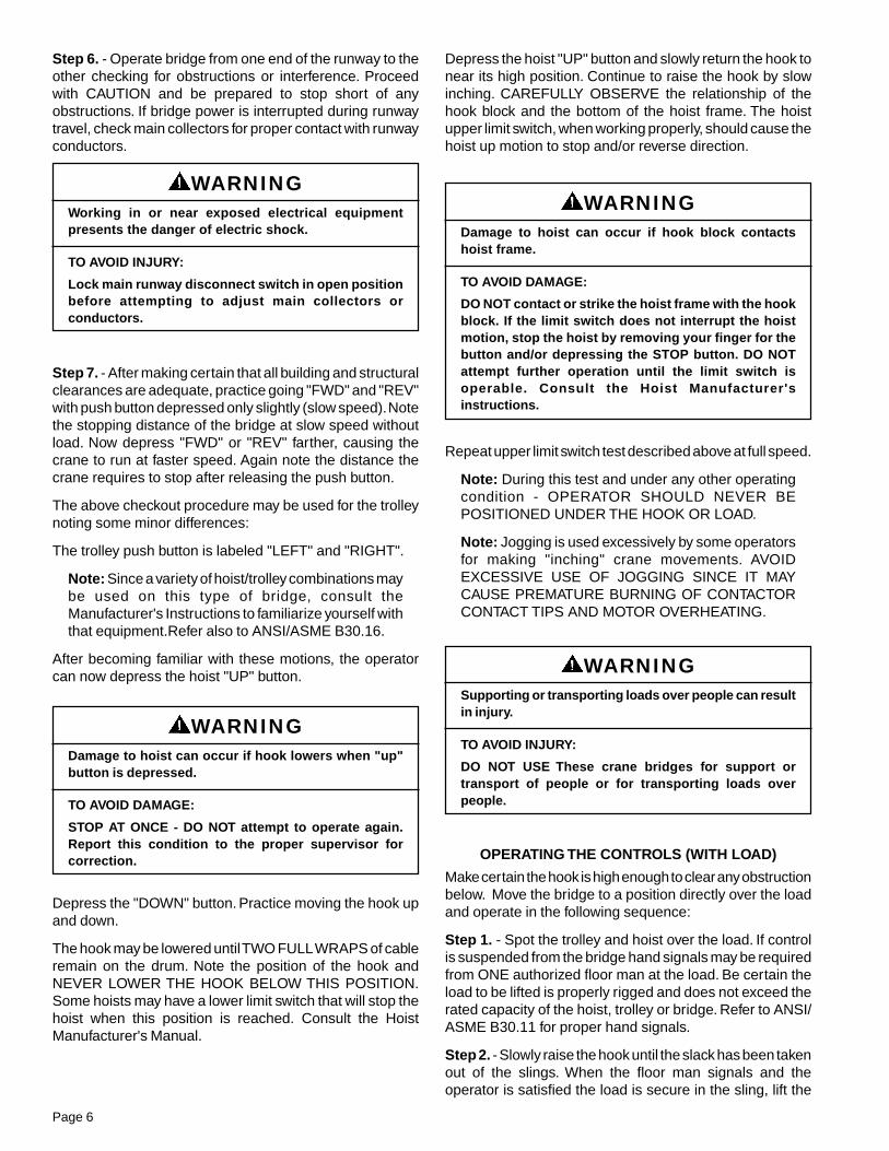
Refer to parts illustration Figure 2.
To remove the wheels follow the steps below:
1. Remove any load from hook and move trolley to theopposite end of the bridge.
2. Remove two bolts and lock washers (Ref. No. 10 & 11) andremove drop lug (Ref. No. 9)
3. Remove load from wheel. This can be accomplished byjacking a very small distance.
4. Remove the hairpin clip (Ref. No. 17) and spacer washer(Ref. No. 16) from the axle.
5. The wheel axle (Ref. No. 8) is held in position by a jam nut(Ref. No. 7) on the adjusting bolt (Ref. No. 6). Removal of thisbolt allows removal of the axle.
6. Pull the axle away from truck. Prevent the wheel fromfalling. Completely remove the axle from the truck and storein a safe place.
7. The wheel is now free. Roll the wheel along the cranerunway, maintaining a secure hold so that the wheel doesnot fall from the runway.
8. An internal snap ring (Ref. No. 13) separates the bearings(Ref. No. 12). It is recommended that bearings and wheelsbe replaced as a unit.
9. Replace wheels in reverse order of disassembly.
GEAR CASE
The gear case is shown in 113533-82, Operating Instructionsand Parts List, Bridge Drive Gear Case.
ELECTRICAL
1. Motors.a. The bridge motors are either single or two-speed. It isrecommended that if any work is required, the motor bereturned to the crane builder.
b. For hoist and trolley motors, consult the hoist and trolleyliterature.
2. Brake.a. Consult the literature provided with the brake for frictiondisc replacement and brake adjustment.
3. Bridge Control Panel.
a. All connections should be checked frequently for tightness.
b. Figure 8 shows components in the electrical enclosureand their identifying numbers.
4. Hoist and Trolley.
a. Panel, brakes, limit switches, etc. Consult hoist and trolleyliterature for maintenance and spare parts information.
REPLACEMENT PARTS
The following parts lists and illustrations cover standardmodel cranes. Typical units are used as the basis for theexploded parts illustrations; therefore, certain variationsmay occur from the parts information given. For this reasonalways give the catalog number, model number, motorhorsepower, voltage, phase and frequency when orderingreplacement parts. For motors, gear cases and electricalcomponents, give complete nameplate data.
The factory recommends complete replacement of themotor or gear case. Motor or gear case service is available,however, from your crane builder.
Note:
The numbers assigned to the parts of the variousassemblies in the parts lists are not the part numbersused in manufacturing the part. They are identificationnumbers, that when given with the catalog numberpermits us to identify, select or manufacture, and shipthe correct part needed.
Injury to personnel and/or damage to equipment canoccur when truck wheel is removed if properinstructions are not followed.
TO AVOID INJURY OR DAMAGE:
Make sure that the truck is adequately supported sothat it cannot drop when the wheel is removed.
WARNING
NON-FACTORY AUTHORIZATIONS OR MODIFICATIONOF EQUIPMENT AND USE OF NON-FACTORY REPAIRPARTS CAN LEAD TO DANGEROUS OPERATION ANDINJURY.
TO AVOID INJURY:
DO NOT alter or modify equipment without factoryauthorization.
DO use only factory provided replacement parts.
WARNING
Page 9 Figure 2. End Truck Assembly

Page 10
ReferenceNumber
Part Number
QuantityRequired Description
6-1/2"Wheels
8"Wheels
1
TRK-901 TRK-902
2
Truck Side 54' Wheelbase
TRK-903 TRK-904 Truck Side 72' Wheelbase
TRK-905 TRK-906 Truck Side 90' Wheelbase
2 TRK-907 TRK-908 4 Flat
3TRK-909
8
Washer Hardened 1/2"
TRK-910 Washer Hardened 5/8"
4TRK-911 Spring Washer 1/2"
TRK-912 Spring Washer 5/8"
5TRK-913 Screw Cap SOC HD1/2-13 X 1-3/4
TRK-914 Screw Cap SOC HD 5/8-11 X 2
6TRK-915
4
Tap Bolt 3/4-10 X 4-1/4" Grade 5
TRK-916 Tap Bolt 1-8 X 4-1/4" Grade 5
7TRK-917 Nut Hex Jam Heavy 3/4-10 Plated
TRK-918 Nut Hex Jam Heavy 1"-8 Plated
8 TRK-919 TRK-920 Axle
9 TRK-921 TRK-922 Drop Lug
10TRK-923
8
LockWasher 3/4"
TRK-924 LockWasher 1" Medium Plated
11TRK-925 Bolt 3/4-10 X 1 3/4 ASTM A 325 Plain
TRK-926 Bolt 1"-8 X 2-1/4 ASTM A 325 Plain
12 TRK-927 TRK-928 Bearing
13 TRK-929 TRK-930 4 Retaining Ring
14 TRK-931 TRK-9322
Driver Wheel
15 TRK-933 TRK-934 Trailer Wheel
16 TRK-935 TRK-9364
Spacer Washer
17 TRK-937 TRK-938 Hitch Pin
18 TRK-939 TRK-939 2 Key
19TRK-940 TRK-940
1Cross Shaft Flange Width 4-5/8 TO 7-1/2
TRK-941 TRK-941 Cross Shaft Flange Width 7-5/8 TO 12
20 TRK-942 TRK-9422
Retaining Ring
21 TRK-943 TRK-943 Cross Shaft Pinion
22 TRK-944 TRK-944 4 Clamp Collar
23 TRK-945 TRK-945
2
Bearing
24
TRK-946 TRK-946 Spacer Block Flange Width 4 5/8 - 6
TRK-947 TRK-947 Spacer Block Flange Width 6 1/8 - 7 1/2
TRK-948 TRK-948 Spacer Block Flange Width 7 5/8 - 9
TRK-949 TRK-949 Spacer Block Flange Width 9 1/8 - 10 1/2
TRK-950 TRK-950 Spacer Block Flange Width 10 5/8 - 12
25 TRK-951 TRK-951 4 Dowel Pin
26 TRK-923 TRK-9238
LockWasher 3/4"
27 TRK-952 TRK-952 Bolt Heavy Hex HD 3/4-10 X 2-1/2
28 TRK-953 TRK-953
4
Bumper Spacer
29TRK-954 Bumper Size 40
TRK-955 Bumper Size 50
Figure 2. End Truck Assembly

Page 11
ReferenceNumber
PartNumber
QuantityRequired Description
1234
TRK - 301TRK - 305TRK - 303TRK - 304
2221
Hex Head Fit Bolt (3/8-16 x 2-1/2)Spring Lockwasher - Plated (3/8)Heavy Semi-Finish Hex Nut (3/8-16)Coupling
ReferenceNumber
PartNumber
QuantityRequired Description
12345
TRK - 201– –
TRK - 202TRK - 203TRK - 204
11222
Pillow BlockLocking Collar (Included with Pillow Block)Hex Head Bolt (1/2-13 x 1-1/4)Spring Lockwasher (1/2)Hex Nut (1/2)
Figure 3. Cross Shaft Bearing Assembly. (Catalog Number 904625).
12831
12731B
Figure 4. Coupling. (Catalog Number 8280).

Page 12
ReferenceNumber
PartNumber
QuantityRequired Description
12
345
TRK - 401TRK - 410
TRK - 403TRK - 404TRK - 405
36 feet1
111
Catalog Number 8282 Consists of Ref. Nos. 1 and 2: Hand Chain Connecting LinkHand Chain DriveCatalog Number 913115 Consists of Ref. Nos. 3 thru 5 Hex Socket Set Screw (1/2-13 x 1) Hand Chain Wheel Chain Wheel Guide
12732C
Figure 5. Hand Chain Drive. (Catalog Numbers 8282 and 913115).
NOTES

Page 13
12974
Figure 6. Hand Geared Adapter.
ReferenceNumber
PartNumber
QuantityRequired Description
12345678
91011
TRK - 501TRK - 502TRK - 503TRK - 504TRK - 505TRK - 506TRK - 511
TRK - 508TRK - 513TRK - 509TRK - 510TRK - 512
11122121
441
Machined Housing WeldmentOutput ShaftWoodruff KeyExternal Retaining RingBall BearingsInternal Retaining RingOpen Square Section Retaining RingsOutput Pinion - 19 Teeth Standard Spark Resistant Application OnlyHi-Collar Spring Lock Washer - Plated - 3/8Socket Head Cap Screw - Plated - 3/8-16 x 3/4Wheel Gear Grease (Not Shown)

Page 14
12976C
Figure 7. Drive Assembly.
ReferenceNumber
PartNumber
QuantityRequired Description
1
234
56
TRK - 601TRK - 602TRK - 603TRK - 604TRK - 666
TRK - 667TRK - 668TRK - 669TRK - 664TRK - 665
TRK - 670TRK - 671TRK - 609
TRK - 610TRK - 611TRK - 612TRK - 613TRK - 614TRK - 615TRK - 616TRK - 617
1
11
441
11
Gear Case - See 113533-82, Operating Instructions and Parts List,Bridge Drive Gear Case 13.04 : 1 Ratio 8.96 : 1 Ratio 6.97 : 1 Ratio 6.08 : 1 Ratio Truck Mounting Hardware (Not Shown) - Includes required Vent Plug and Wheel Gear Grease Motor Mounting Hardware - Includes Coupling (Not Shown) For Motor with 56C Frame For Motor with 145TC Frame For Motor with 180C FrameHi-Collar Spring Lock Washers (3/8 - Plated)Socket Head Cap Screw (3/8-16 x 2 - Plated)Coupling For 56C Face Motor For 145TC and 180C Face MotorPlain Parallel Key (3/16 x 3/16 x 1)Motor: Single Speed: 208-230/460-3-60: 1/2 HP, 1200 RPM 3/4 HP, 1200 RPM 1 HP, 1200 RPM 1/2 HP, 1800 RPM 3/4 HP, 1800 RPM 1 HP, 1800 RPM 1-1/2 HP, 1800 RPM 2 HP, 1800 RPM

Page 15
Figure 7. Drive Assembly (continued)
ReferenceNumber
PartNumber
QuantityRequired Description
6
78
9
1011
12
TRK - 619TRK - 620TRK - 621TRK - 622TRK - 623TRK - 624TRK - 625TRK - 626TRK - 627
TRK - 628TRK - 629TRK - 630TRK - 631TRK - 632TRK - 633TRK - 634TRK - 635TRK - 636
TRK - 637TRK - 638TRK - 639TRK - 640TRK - 641TRK - 642TRK - 643TRK - 644TRK - 645
TRK - 646TRK - 647TRK - 648TRK - 649TRK - 650TRK - 651TRK - 652TRK - 653
TRK - 655TRK - 656
TRK - 657TRK - 658TRK - 659TRK - 660TRK - 661
TRK - 662
TRK - 664TRK - 663
1
121
4
4
44
Motor: (continued) Single Speed: (continued) 575-3-60: 1/2 HP, 1200 RPM 3/4 HP, 1200 RPM 1 HP, 1200 RPM 1/2 HP, 1800 RPM 3/4 HP, 1800 RPM 1 HP, 1800 RPM 1-1/2 HP, 1800 RPM 2 HP, 1800 RPM 3 HP, 1800 RPM Two Speed: 230-3-60 .5/.25 HP, 1200/600 RPM .75/.38 HP, 1200/600 RPM 1/.5 HP, 1200/600 RPM .5/.17 HP 1800/600 RPM .75/.25 HP, 1800/600 RPM 1/.33 HP 1800/600 RPM 1.5/.5 HP 1800/600 RPM 2/.67 HP, 1800/600 RPM 3/1 HP, 1800/600 RPM 460-3-60: .5/.25 HP, 1200/600 RPM .75/.38 HP, 1200/600 RPM 1/.5 HP, 1200/600 RPM .5/.17 HP 1800/600 RPM .75/.25 HP, 1800/600 RPM 1/.33 HP 1800/600 RPM 1.5/.5 HP 1800/600 RPM 2/.67 HP, 1800/600 RPM 3/1 HP, 1800/600 RPM 575-3-60: .5/.25 HP, 1200/600 RPM .75/.38 HP, 1200/600 RPM 1/.5 HP, 1200/600 RPM .5/.17 HP 1800/600 RPM .75/.25 HP, 1800/600 RPM 1/.33 HP 1800/600 RPM 1.5/.5 HP 1800/600 RPM 2/.67 HP, 1800/600 RPM
Plain Parallel Key (3/16 x 3/16 x 1)Self Locking Hex Socket Set Screw - Cup Point 5/16-24 x 1/2Brake: 230 or 460V thru 1-1/2 HP 575V thru 1-1/2 HP 230V or 460V over 1-1/2 HP 575V over 1-1/2 HPSpring Lock Washer - Plated 3/8For All Motors Except Those With 180C Frame:Hex Head Bolt - Plated - 3/8-16 x 1For Motors With 180C Frame:Hex Head Bolt - Plated - 3/8-16 x 1-1/2Hardened Flat Washer - 3/8

Page 16
ReferenceNumber
PartNumber
QuantityRequired Description
1
2
9
TRK - 701TRK - 702
TRK - 703TRK - 704TRK - 705
TRK - 706TRK - 707
TRK - 770TRK - 771TRK - 772TRK - 773TRK - 774TRK - 775TRK - 776TRK - 777TRK - 778TRK - 779TRK - 780TRK - 781
1
3
1
1
Fused Disconnect Switch Thru 3 HP Over 3 HP Replacement Fuses - 600V 15 Amp 30 Amp 60 AmpMainline Contactor Thru 3 HP Over 3 HPDynamic Braking Resistor (not shown) 1 HP 230 Volt 2 HP 230 Volt 3 HP 230 Volt 5 HP 230 Volt 7.5 HP 230 Volt 10 HP 230 Volt 1 HP 460 Volt 2 HP 460 Volt 3 HP 460 Volt 5 HP 460 Volt 7.5 HP 460 Volt 10 HP 460 Volt
�
�
�
� ��
�
�
Figure 8. Electrical Enclosure.
Page 17
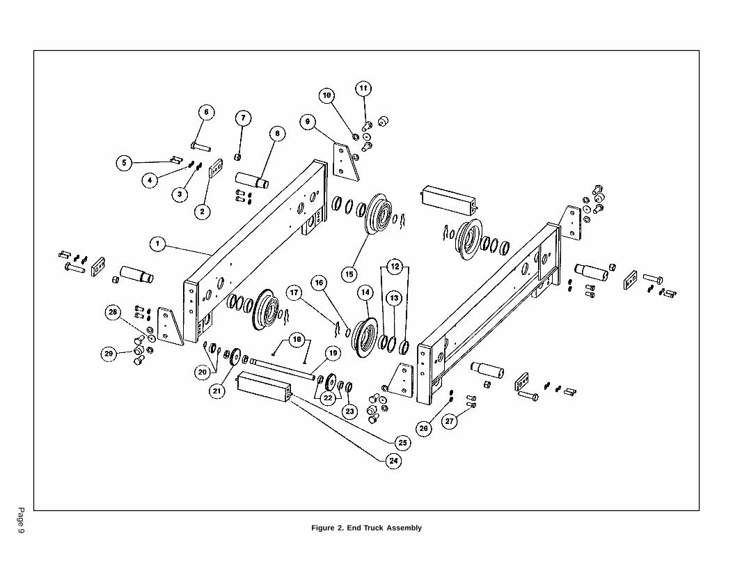
Figure 8. Electrical Enclosure (continued).
ReferenceNumber
PartNumber
QuantityRequired Description
3
4
56
78
TRK - 708
TRK - 709TRK - 710TRK - 711TRK - 712TRK - 713TRK - 714TRK - 715TRK - 716TRK - 717TRK - 718TRK - 719TRK - 720
TRK - 753TRK - 754TRK - 755TRK - 756TRK - 757TRK - 758TRK - 759TRK - 760TRK - 761TRK - 762TRK - 763TRK - 764
TRK - 733TRK - 734TRK - 735
TRK - 736TRK - 737TRK - 738TRK - 739
TRK - 740TRK - 741TRK - 742TRK - 743TRK - 744TRK - 745
TRK - 746TRK - 747TRK - 748TRK - 749TRK - 750TRK - 765TRK - 752
13
1
11
3
31
Fuse Base Fuses - 600V 2 Amp 3 Amp 4 Amp 5 Amp 6 Amp 8 Amp 10 Amp 12 Amp 15 Amp 20 Amp 25 Amp 30 AmpVariable Frequency Drive or Reversing Contactor for One and Two SpeedPlus An Accelerating Contactor for Two Speed Only. Variable Frequency Drive 1 HP, 230V 2 HP, 230V 3 HP, 230V 5 HP, 230V 7.5 HP, 230V 10 HP, 230V 1 HP, 460V 2 HP, 460V 3 HP, 460V 5 HP, 460V 7.5 HP, 460V 10 HP, 460V Reversing Contactor for One and Two Speed 3 HP, 200 & 230V; 7.5 HP, 460V; 10 HP, 575V 7.5 HP, 200 & 230V; 15 HP, 460V; 20 HP, 575V 10 HP, 200 & 230V; 30 HP, 460V; 30 HP, 575V Accelerating Contactor for Two Speed Only 3 HP, 200 & 230V; 7.5 HP, 460V; 10 HP, 575V 7.5 HP, 200 & 230V; 15 HP, 460V; 20 HP, 575V 10 HP, 200 & 230V; 30 HP, 460V; 30 HP, 575VBrake Relay (For V.F.C. Control)Fused Transformer 75VA, 230/460V 75VA, 208/277V 75VA, 575V 100VA, 230/460V 100VA, 208/277V 100VA, 575V Fuses - 600V .6 Amp .8 Amp 1 Amp 1.4 Amp 2 AmpTerminal BoardsGround Lug
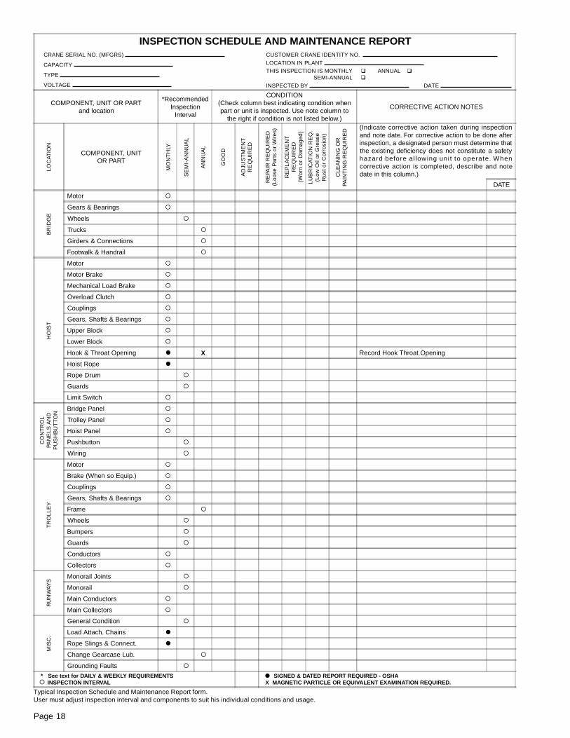
Page 18
INSPECTION SCHEDULE AND MAINTENANCE REPORT
COMPONENT, UNIT OR PARTand location
*RecommendedInspection
Interval
CONDITION(Check column best indicating condition whenpart or unit is inspected. Use note column to
the right if condition is not listed below.)
CORRECTIVE ACTION NOTES
COMPONENT, UNITOR PART
(Indicate corrective action taken during inspectionand note date. For corrective action to be done afterinspection, a designated person must determine thatthe existing deficiency does not constitute a safetyhazard before al lowing uni t to operate. Whencorrective action is completed, describe and notedate in this column.)
DATE
Motor �
Gears & Bearings �
Wheels �
Trucks �
Girders & Connections �
Footwalk & Handrail �
Motor �
Motor Brake �
Mechanical Load Brake �
Overload Clutch �
Couplings �
Gears, Shafts & Bearings �
Upper Block �
Lower Block �
Hook & Throat Opening � X Record Hook Throat Opening
Hoist Rope �
Rope Drum �
Guards �
Limit Switch �
Bridge Panel �
Trolley Panel �
Hoist Panel �
Pushbutton �
Wiring �
Motor �
Brake (When so Equip.) �
Couplings �
Gears, Shafts & Bearings �
Frame �
Wheels �
Bumpers �
Guards �
Conductors �
Collectors �
Monorail Joints �
Monorail �
Main Conductors �
Main Collectors �
General Condition �
Load Attach. Chains �
Rope Slings & Connect. �
Change Gearcase Lub. �
Grounding Faults �
* See text for DAILY & WEEKLY REQUIREMENTS INSPECTION INTERVAL
SIGNED & DATED REPORT REQUIRED - OSHA X MAGNETIC PARTICLE OR EQUIVALENT EXAMINATION REQUIRED.
LOC
ATIO
N
MO
NT
HLY
SE
MI-
AN
NU
AL
AN
NU
AL
GO
OD
AD
JUS
TM
EN
TR
EQ
UIR
ED
RE
PLA
CE
ME
NT
RE
QU
IRE
D(W
orn
or D
amag
ed)
CLE
AN
ING
OR
PAIN
TIN
G R
EQ
UIR
ED
LUB
RIC
ATIO
N R
EQ
.(L
ow O
il or
Gre
ase
Rus
t or
Cor
rosi
on)
RE
PAIR
RE
QU
IRE
D(L
oose
Par
ts o
r W
ires
)
HO
IST
CO
NT
RO
LPA
NE
LS A
ND
PU
SH
BU
TT
ON
TR
OLL
EY
RU
NW
AYS
MIS
C.
�
�
CRANE SERIAL NO. (MFGRS)
CAPACITY
TYPE
VOLTAGE
CUSTOMER CRANE IDENTITY NO. LOCATION IN PLANT THIS INSPECTION IS MONTHLY � ANNUAL �
SEMI-ANNUAL �
INSPECTED BY DATE
BR
IDG
E
Typical Inspection Schedule and Maintenance Report form.User must adjust inspection interval and components to suit his individual conditions and usage.

NOTES

Recommended Spare Parts for
Your Crane Bridge
Certain parts of your crane will, in time, require replacement under normal wear conditions. It is suggested that the followingparts be purchased for your crane as spares for future use.
1 Set of Wheels1 Set of Wheel Bearings1 Set of Fuses1 Set of Contactors
NOTE: When ordering parts always furnish Catalog Number and Part Number.
Parts for your crane are available from your authorized repair station. For the location of your nearest repair station, write:
A. Seller warrants that its products and parts, when shipped, and itswork (including installation, construction and start-up), whenperformed, will meet applicable specifications, will be of good qualityand will be free from defects in material and workmanship. All claimsfor defective products or parts under this warranty must be made inwriting immediately upon discovery and, in any event, within one (1)year from shipment of the applicable item unless Seller specificallyassumes installation, construction or start-up responsibility. All claimsfor defective products or parts when Seller specifically assumesinstallation, construction or start-up responsibility, and all claims fordefective work must be made in writing immediately upon discoveryand, in any event, within one (1) year from completion of theapplicable work by Seller, provided, however, all claims for defectiveproducts and parts made in writing no later than eighteen (18) monthsafter shipment. Defective items must be held for Seller’s inspectionand returned to the original f.o.b. point upon request. THE‘FOREGOING IS EXPRESSLY IN LIEU OF ALL OTHERWARRANTIES WHATSOEVER, EXPRESS, IMPLIED ANDSTATUTORY, INCLUDING, WITHOUT LIMITATION, THE IMPLIEDWARRANTIES OF MERCHANTABILITY AND FITNESS.
WARRANTYWARRANTY AND LIMITATION OF REMEDY AND LIABILITY
B. Upon Buyer’s submission of a claim as provided above and itssubstantiation, Seller shall at its option either (i) repair or replace itsproduct, part or work at either the original f.o.b. point of delivery or atSeller’s authorized service station nearest Buyer or (ii) refund anequitable portion of the purchase price.
C. This warranty is contingent upon Buyer’s proper maintenance andcare of Seller’s products, and does not extend to normal wear andtear. Seller reserves the right to void warranty in event of Buyer’s useof inappropriate materials in the course of repair or maintenance, orif Seller’s products have been dismantled prior to submission to Sellerfor warranty inspection.
D. The foregoing is Seller’s only obligation and Buyer’s exclusiveremedy for breach of warranty, and is Buyer’s exclusive remedyhereunder by way of breach of contract, tort, strict liability or otherwise.In no event shall Buyer be entitled to or Seller liable for incidental orconsequential damages. Any action for breach of this agreementmust be commenced within one (1) year after the cause of action hasaccrued.
414 West Broadway AvenueP.O. Box 769
Muskegon, Michigan 49443-0769(800) 742-9269 Phone
(800) 742-9270 Fax