Embed Size (px)
Citation preview
16.1 Rev: 12/14 95-8533
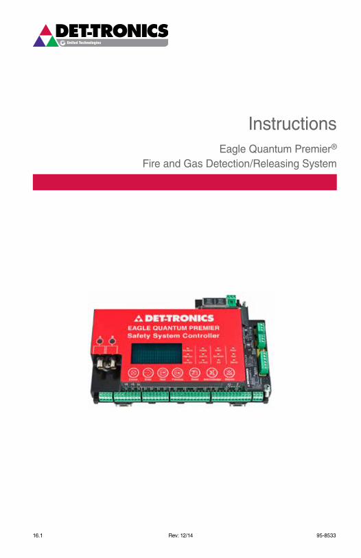
InstructionsEagle Quantum Premier®
Fire and Gas Detection/Releasing System

2 95-853316.1
Table of ContentsSection 1 - Safety
Alert MessAges ...................................................... 1-1
Section 2 - IntroductionsYsteM DesCrIPtION .............................................. 2-1 Communications loop ................................................... 2-1 lON Communication Heartbeat ..................................... 2-2 theory of Operation ....................................................... 2-3 Controller logs ............................................................... 2-4 Controller User logic ..................................................... 2-4 Communication Network Fault Operation ...................... 2-5 Multiple Wiring Faults ..................................................... 2-5
MAJOr COMPONeNt DesCrIPtIONs .....................2-6 system Controller ........................................................... 2-6 Controller redundancy ............................................... 2-6 ethernet Interface Board ............................................. 2-7 serial Interface Board ................................................. 2-7 ControlNet Board or ethernet Dlr Board ................... 2-7 Controller-to-Controller Communication ...................... 2-8 eQP supervising system............................................. 2-8 eQP Marine Application system ................................. 2-8 local Operating Network (lON)..................................... 2-8 Network extenders ...................................................... 2-8 eQ21xxPs series Power supplies and eQ2100PsM Power supply Monitor ............................ 2-9 eQP21xxPs(–X) Power supplies and eQP2410Ps(–P) Converter .......................................... 2-9 eQ2220gFM ground Fault Monitor ............................. 2-9 Field Devices .................................................................. 2-9 Flame Detectors .......................................................... 2-9 eQ3730eDIO enhanced Discrete I/O Module ............ 2-9 eQ3700 8 Channel DCIO Module ............................. 2-10 eQ3720 8 Channel relay Module ............................. 2-11 eQ3710AIM Analog Input Module............................. 2-11 eQ3750AsH Addressable smoke & Heat Module .... 2-12 eQ25xxArM Agent release Module......................... 2-13 eQ25xxsAM signal Audible Module ......................... 2-14 eQ22xxIDC series Initiating Device Circuit ............... 2-14 eQ22xxDCU / eQ22xxDCUeX Digital Communication Units ................................................ 2-15 PIreCl PointWatch eclipse ...................................... 2-15 OPeCl Open Path eclipse ........................................ 2-15 UD10 DCU emulator ................................................. 2-15
Section 3 - InstallationsAFetY sYsteM DesIgN reQUIreMeNts ............. 3-1 Identifying the Area of Protection ................................... 3-1 Identifying Wiring, Network (lON), and system Power requirements .................................. 3-1 general Wiring requirements ..................................... 3-1 Power Wiring ............................................................... 3-1 system Wiring (AteX and IeCex) ................................ 3-1 Determining Power requirements............................... 3-3 eQ211xPs, eQ213xPs and eQ217xPs Power supplies ........................................................... 3-5 Backup Battery ............................................................ 3-5 Battery Charger ........................................................... 3-5 eQP21x0Ps(–X) Power supplies ................................. 3-5 eQP2410Ps(–P) Converter .......................................... 3-6 Determining Power requirements............................... 3-6 shield grounding ........................................................ 3-7 Junction Box grounding.............................................. 3-7 response time vs. system size ................................. 3-7 Moisture Damage Protection ....................................... 3-7 electrostatic Discharge ............................................... 3-7
grOUND FAUlt MONItOr (gFM) INstAllAtION ......3-8 Mounting......................................................................... 3-8 Wiring ............................................................................ 3-8
NetWOrk & NetWOrk eXteNDer INstAllAtION ...3-8 Mounting......................................................................... 3-8 Wiring ............................................................................ 3-8
INItIAtINg DevICe CIrCUIt (IDC) INstAllAtION 3-11 eQ22xxIDC series Initiating Device Circuit .................. 3-11 Mounting ................................................................... 3-11 Wiring ........................................................................ 3-11 eQ22xxIDCgF series Initiating Device Circuit ground Fault ..................................................... 3-12 Mounting ................................................................... 3-12 Wiring ........................................................................ 3-12 eQ22xxIDCsC series Initiating Device Circuit short Circuit ...................................................... 3-13 Mounting ................................................................... 3-13 Wiring ........................................................................ 3-13

95-8533316.1
Table of Contents – ContinuedeQ3XXX CONtrOller INstAllAtION ................. 3-13 enclosure requirements .............................................. 3-13 Mounting....................................................................... 3-14 serial Interface Board................................................... 3-14 ethernet Interface Board .............................................. 3-14 Wiring .......................................................................... 3-14 Power Wiring ............................................................. 3-14 electrical Connections .............................................. 3-14 Controller to Controller Communication ....................... 3-19 Configuration ................................................................ 3-23 software Defined Addresses ..................................... 3-23
eQ3XXX reDUNDANt CONtrOller INstAllAtION ..........................................................3-25 enclosure requirements .............................................. 3-25 Mounting....................................................................... 3-25 Wiring .......................................................................... 3-25 lON Wiring ................................................................... 3-25 High speed serial link (Hssl) .................................... 3-26 Configuration ................................................................ 3-26 s³ Configuration ......................................................... 3-26 Controller Addresses ................................................. 3-26 rs485/rs232 ............................................................ 3-26 ControlNet ................................................................. 3-26 ethernet Dlr ............................................................. 3-26 ethernet ..................................................................... 3-26
eQ21XXPs serIes POWer sUPPlY AND POWer sUPPlY MONItOr INstAllAtION............3-26 Mounting....................................................................... 3-27 Wiring .......................................................................... 3-27 startup .......................................................................... 3-27Measuring Battery voltage and Charging Current .......... 3-28
eQP2XX0Ps(–X) POWer sUPPlIes AND reDUNDANCY MODUle INstAllAtION ...............3-29 Mounting....................................................................... 3-29 Wiring .......................................................................... 3-29 startup .......................................................................... 3-32
eDIO MODUle INstAllAtION ................................3-32 Configuration ................................................................ 3-36
8 CHANNel DCIO INstAllAtION .......................3-37 Mounting....................................................................... 3-37 Wiring .......................................................................... 3-37 Configuration ................................................................ 3-41
8 CHANNel relAY MODUle INstAllAtION........3-41 Mounting....................................................................... 3-41 Wiring .......................................................................... 3-41 Configuration ................................................................ 3-42
ANAlOg INPUt MODUle INstAllAtION .............3-43 Mounting....................................................................... 3-43 Wiring .......................................................................... 3-43 Configuration ................................................................ 3-44
gAs DeteCtOr lOCAtION AND INstAllAtION .3-45 environments and substances that Affect gas Detector Performance .......................................... 3-46 eQ22xxDCU Digital Communication Unit used with Det-tronics H2s/O2 sensors or other two-Wire 4-20 mA Devices .......................................................... 3-47 Assembly and Wiring Procedure ............................... 3-47 sensor separation for DCU with H2s and O2 sensors......................................................................... 3-47 eQ22xxDCU Digital Communication Unit used with PointWatch/DuctWatch ................................................. 3-48 Assembly and Wiring Procedure ............................... 3-48 sensor separation for DCU with PointWatch ............... 3-49 eQ22xxDCUeX Digital Communication Unit (used with Det-tronics Combustible gas sensors) ....................... 3-49 Mounting ................................................................... 3-49 Wiring ........................................................................ 3-49 sensor separation with DCUeX ................................... 3-51 eQ25xxArM series Agent release Module................. 3-52 Mounting ................................................................... 3-52 Wiring ........................................................................ 3-52 supervised Output for Deluge and Pre-action ............. 3-53 Jumpers .................................................................... 3-54 Address setting ......................................................... 3-54 eQ25xxsAM series signal Audible Module ................ 3-54 Mounting ................................................................... 3-54 Wiring ........................................................................ 3-54 Jumpers .................................................................... 3-55 Address setting ......................................................... 3-55
sYsteM CONFIgUrAtION ......................................3-56 setting Device Network addresses .............................. 3-56 Overview of Network Addresses ............................... 3-56 setting Field Device Addresses ................................ 3-56
tYPICAl APPlICAtIONs ..........................................3-56
4 95-853316.1
Table of Contents – ContinuedSection 4 - Operation
sYsteM CONtrOller .............................................. 4-1 Pushbuttons.................................................................... 4-1 Controller status Indicators ............................................ 4-2 text Display .................................................................... 4-2 Controller Menu Options ................................................ 4-2 Controller Audible Alarm ................................................ 4-6 ControlNet status Indicators (Optional) ......................... 4-7 ethernet Dlr status Indicators ...................................... 4-7 sequence of events During a Configuration Data Download ............................................................... 4-8 Controller redundancy .................................................. 4-9
eNHANCeD DIsCrete I/O MODUle ...................... 4-11 Power-Up sequence .................................................... 4-11
8 CHANNel DCIO MODUle .................................... 4-12 Power-Up sequence .................................................... 4-12
8 CHANNel relAY MODUle .................................. 4-13 Power-Up sequence .................................................... 4-13
ANAlOg INPUt MODUle ........................................ 4-14 Power-Up sequence .................................................... 4-14
eQ21XXPsM POWer sUPPlY MONItOr ................ 4-15
eQ2220gFM grOUND FAUlt MONItOr ............... 4-15
eQ22XXIDC serIes INItIAtINg DevICe CIrCUIt 4-16
eQ22XXDCU AND eQ22XXDCUeX DIgItAl COMMUNICAtION UNIts ........................................ 4-16
eQ25XXArM AgeNt releAse MODUle............... 4-17
eQ25XXsAM sIgNAl AUDIBle MODUle .............. 4-17
eQ24XXNe NetWOrk eXteNDer ......................... 4-17
sYsteM stArtUP .................................................... 4-18 Pre-Operation Checks .................................................. 4-18 general start-up Procedures ....................................... 4-19 startup Procedure for Controller .................................. 4-20 startup Procedure for eDIO Module ............................ 4-20 startup Procedure for DCIO Module ............................ 4-21

95-8533516.1
Table of Contents – ContinuedSection 5 - Maintenance
rOUtINe MAINteNANCe .......................................... 5-1 Batteries ......................................................................... 5-1 Manual Check of Output Devices .................................. 5-1 O-ring Maintenance ...................................................... 5-1
gAs seNsOr MAINteNANCe ................................... 5-1
CAlIBrAtION AND ADJUstMeNts .........................5-2 Calibration Algorithm A For Manual Calibration of Universal DCU ............................................................ 5-2 Normal Calibration ...................................................... 5-2 sensor replacement ................................................... 5-3 Calibration Algorithm C For Combustible gas DCUs and Automatic Calibration of Universal DCUs ............... 5-3 routine Calibration ...................................................... 5-3 Initial Installation and sensor replacement — Combustible gas ........................................................ 5-4 sensor replacement — toxic gas.............................. 5-5 Calibration Algorithm D For Universal DCUs with O2 sensor ............................................................... 5-5 Normal Calibration ...................................................... 5-5 sensor replacement ................................................... 5-5 Calibration Algorithm g For DCUs with PointWatch or DuctWatch .................................................................. 5-6 routine Calibration ...................................................... 5-6 sensor replacement ................................................... 5-6
DevICe CAlIBrAtION lOgs AND reCOrDs ......... 5-7
trOUBlesHOOtINg ................................................. 5-7
rePlACeMeNt PArts ............................................... 5-7
DevICe rePAIr AND retUrN .................................. 5-7
OrDerINg INFOrMAtION ........................................5-9
Power supplies .........................................................5-9
lON Devices .............................................................5-9
redundancy ..............................................................5-9
Controller Communication Cables ...........................5-9
Section 6 - SpecificationseQ3XXX Controller ............................................................ 6-1eQ3ltM lON termination Module .................................... 6-3eQ3730eDIO enhanced Discrete I/O Module ................. 6-3eQ3700 DCIO Module ....................................................... 6-5eQ3720 relay Module ....................................................... 6-7eQ3710AIM Analog Input Module ..................................... 6-7HArt Interface Module ..................................................... 6-8eQ21xxPs Power supplies ................................................ 6-8eQP2xx0Ps(–x) Power supplies ....................................... 6-9redundancy Module Quint-Diode/40 ................................ 6-9eQ21xxPsM Power supply Monitor ................................ 6-10eQ22xxIDC series Initiating Device Circuit ..................... 6-10eQ2220gFM ground Fault Monitor ................................. 6-11eQ22xxDCU series Digital Communication Unit ............ 6-12eQ25xxArM Agent release Module ............................... 6-13eQ25xxsAM signal Audible Module ............................... 6-14eQ24xxNe Network extender .......................................... 6-15eQ3750AsH Addressable smoke & Heat Module .......... 6-16Combustible gas sensor ................................................ 6-16electrochemical sensors ................................................. 6-16eQ21xxPs Power supply ................................................ 6-16
AppendixAPPeNDIX A — FM APPrOvAl DesCrIP. .................A-1
APPeNDIX B — CsA CertIFICAtION DesCrIP..........B-1
APPeNDIX C — AteX AND IeCeX CertIFICAtION ..C-1
APPeNDIX D — eQP MArINe, UsCg APPrOvAl .....D-1
APPeNDIX e — Ce MArk ........................................... e-1
APPeNDIX F — rOCker sWItCH tABle .................. F-1
APPeNDIX g — DevICe MODel MAtrICes ............ g-1

1 95-853316.1
Section 1Safety
Alert MeSSAgeSthe following Alert Messages, DANGER, WARNING, CAUTION, and IMPORTANT are used throughout this manual and on the system to alert the reader and operator to dangerous conditions and/or important operational or maintenance information.
DANGER!
Identifies immediate hazards that WILL
result in severe personal injury or death.
WARNING!
Identifies hazards or unsafe practices that COULD result in severe personal
injury or death.
CAUTION!
Identifies hazards or unsafe practices that COULD result in minor personal injury or damage to equipment or property.
IMPORTANT!
A brief statement of fact, experience or importance that is given as an aid or explanation.
WARNING!
Th e h a z a rd o u s a re a m u s t b e de-classified prior to removing a junction box cover or opening a detector assembly with power applied.
CAUTION!
1. Be sure to read and understand the entire instruction manual before installing or operating the eagle Quantum Premier®
system. Only qualified personnel should install, maintain or operate the system.
2. the wiring procedures in this manual are intended to ensure proper functioning of the devices under normal conditions. However, because of the many variations in wiring codes and regulations, total compliance with these ordinances cannot be guaranteed. Be certain that all wiring and equipment installation meets or exceeds the latest revisions of the appropriate NFPA standards, National electrical Code (NeC), and all local ordinances. If in doubt, consult the Authority Having Jurisdiction (AHJ) before wiring the system. All wiring shall be installed in accordance with the manufacturer’s recommendations.
3. some eagle Quantum Premier devices contain semiconductor devices that are susceptible to damage by electrostatic discharge. An electrostatic charge can build up on the skin and discharge when an object is touched. Always observe the normal precautions for handling electrostatic sensitive devices, i.e. use of a wrist strap (if available) and proper grounding.
4. to prevent unwanted actuation, alarms and extinguishing devices must be secured prior to performing system tests.
Instructions
Eagle Quantum Premier®
Fire and Gas Detection/Releasing System
©Detector Electronics Corporation 2014 Rev: 12/14
95-85332-116.1
Section 2Introduction
SySteM DeScrIptIonthe eagle Quantum Premier (eQP) system combines "fire detection and extinguishing agent release" and "hazardous gas monitoring" in one complete package. the system is intended for use in hazardous locations and is designed to meet the requirements of approval agencies from around the world.
the system consists of a Controller and a number of addressable microprocessor based field devices. the Controller coordinates system device configuration, monitoring, annunciation, and control, while the field devices communicate their status and alarm conditions to the Controller.
the eQP controller can be arranged in a redundant configuration, thereby increasing the availability of the system. the controllers work in “Master” and “Hot standby” mode.
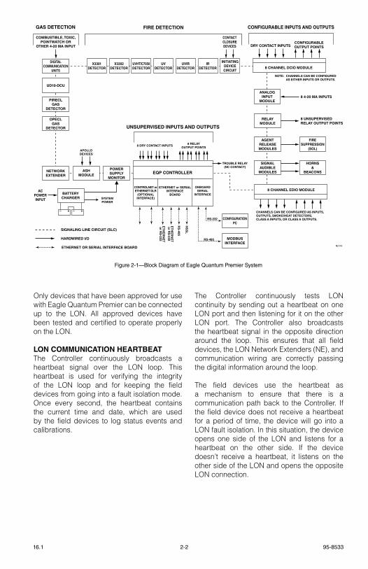
various combinations of field devices can be configured as part of the system. the actual selection depends on the requirements of the application and the regulations that cover the type of protection required. see Figure 2-1 for a block diagram of the eagle Quantum Premier system.
All field devices are tied into a communication loop that starts and ends at the Controller. each device connected to the communication loop is assigned a unique identity by setting its address switches. All other device operation parameters are configured through Det-tronics “safety system software”. these selections define the type of device and how it is to operate. this system configuration data is then downloaded into the Controller.
A programmed Controller is configured to automatically download the configuration data into the individual devices when they first communicate with the Controller.
In addition to Det-tronics advanced flame and gas detectors, eagle Quantum Premier offers the capability of incorporating third party fire and gas protection equipment into the system. these can be either input or output devices. typical input devices include manual fire alarm "call boxes", heat detectors, and
analog combustible or toxic gas measurement instruments. typical output equipment includes solenoids, strobes, and horns. All equipment is monitored for wiring fault conditions.
For complete system integration, the Controller has the capability to communicate with other systems such as PlCs and DCss. Different communication protocols are supported, allowing the Controller to communicate with other systems either directly or through communication gateways.
noTe
For specific information relating to the SIL 2 rated eQP system, refer to manual number 95-8599.
COMMUNICATIONS LOOP
eagle Quantum Premier utilizes a Det-tronics signaling line Circuit (slC), a version of echelon’s local Operation Network (lON) customized specifically for eagle Quantum Premier. this network provides several key advantages:
• ANsI/NFPA Class X performance of slC• Peer-to-peer communications• short message formats• expandability
the Controller utilizes several mechanisms to continuously check the lON loop for fault conditions, thereby providing the highest level of reliable communication.
every device on the lON loop has the ability to communicate with the Controller at any time. this is typically referred to as distributed peer-to-peer communications. this design allows for immediate alarm messages to be sent from the field devices to the Controller.
All messages are kept short in order to maximize network performance. this minimizes network bottlenecks.
the eagle Quantum Premier system is easily modified to accommodate design changes or plant expansions. this can involve adding lON sections, repositioning lON sections, or removing lON sections from the loop. there are lON communication implementation details that affect and limit how the lON loop is changed.
2-2 95-853316.1
Only devices that have been approved for use with eagle Quantum Premier can be connected up to the lON. All approved devices have been tested and certified to operate properly on the lON.
LON COMMUNICATION HEARTBEATthe Controller continuously broadcasts a heartbeat signal over the lON loop. this heartbeat is used for verifying the integrity of the lON loop and for keeping the field devices from going into a fault isolation mode. Once every second, the heartbeat contains the current time and date, which are used by the field devices to log status events and calibrations.
the Controller continuously tests lON continuity by sending out a heartbeat on one lON port and then listening for it on the other lON port. the Controller also broadcasts the heartbeat signal in the opposite direction around the loop. this ensures that all field devices, the lON Network extenders (Ne), and communication wiring are correctly passing the digital information around the loop.
the field devices use the heartbeat as a mechanism to ensure that there is a communication path back to the Controller. If the field device does not receive a heartbeat for a period of time, the device will go into a lON fault isolation. In this situation, the device opens one side of the lON and listens for a heartbeat on the other side. If the device doesn’t receive a heartbeat, it listens on the other side of the lON and opens the opposite lON connection.
CONFIGURATIONPC
MODBUSINTERFACE
NETWORKEXTENDER
DIGITALCOMMUNICATION
UNITS
PIRECLGAS
DETECTOR
UD10-DCU
OPECLGAS
DETECTOR
SIGNALAUDIBLE
MODULES
HORNS&
BEACONS
GAS DETECTION
COMBUSTIBLE, TOXIC,POINTWATCH OR
OTHER 4-20 MA INPUT
RS-232
RS-485
8 DRY CONTACT INPUTS8 RELAY
OUTPUT POINTS
UNSUPERVISED INPUTS AND OUTPUTS
8 CHANNEL DCIO MODULE
DRY CONTACT INPUTSCONFIGURABLEOUTPUT POINTS
CONFIGURABLE INPUTS AND OUTPUTSFIRE DETECTION
UVDETECTOR
UVHT/C7050DETECTOR
X3301DETECTOR
X3302DETECTOR
UVIRDETECTOR
IRDETECTOR
INITIATINGDEVICECIRCUIT
CONTACTCLOSUREDEVICES
SIGNALING LINE CIRCUIT (SLC)
HARDWIRED I/O
ETHERNET OR SERIAL INTERFACE BOARD
EQP CONTROLLER
CONTROLNET orETHERNET DLR
(OPTIONALINTERFACE)
ONBOARDSERIAL
INTERFACE
ETHERNET or SERIALINTERFACE
BOARD
N2114
+–+–
AGENTRELEASEMODULES
FIRESUPPRESSION
(SOL)
POWERSUPPLY
MONITOR
ASHMODULE
APOLLODEVICES
BATTERYCHARGER
ACPOWERINPUT SYSTEM
POWER
NOTE: CHANNELS CAN BE CONFIGURED AS EITHER INPUTS OR OUTPUTS.
TROUBLE RELAY(NC CONTACT)
RELAYMODULE
8 UNSUPERVISEDRELAY OUTPUT POINTS
ANALOGINPUT
MODULE8 4-20 MA INPUTS
ET
HE
RN
ET
or R
S-232
ET
HE
RN
ET
or R
S-232
RS
-485
HS
SL
CHANNELS CAN BE CONFIGURED AS INPUTS, OUTPUTS, SMOKE/HEAT DETECTORS, CLASS A INPUTS, OR CLASS A OUTPUTS.
8 CHANNEL EDIO MODULE
Figure 2-1—Block Diagram of Eagle Quantum Premier System
95-85332-316.1
THEORY OF OPERATION
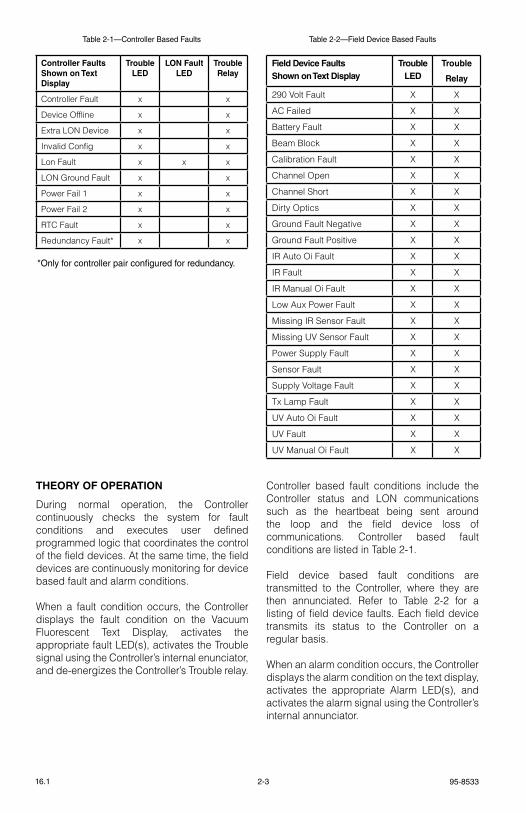
During normal operation, the Controller continuously checks the system for fault conditions and executes user defined programmed logic that coordinates the control of the field devices. At the same time, the field devices are continuously monitoring for device based fault and alarm conditions.
When a fault condition occurs, the Controller displays the fault condition on the vacuum Fluorescent text Display, activates the appropriate fault leD(s), activates the trouble signal using the Controller’s internal enunciator, and de-energizes the Controller’s trouble relay.
Controller based fault conditions include the Controller status and lON communications such as the heartbeat being sent around the loop and the field device loss of communications. Controller based fault conditions are listed in table 2-1.
Field device based fault conditions are transmitted to the Controller, where they are then annunciated. refer to table 2-2 for a listing of field device faults. each field device transmits its status to the Controller on a regular basis.
When an alarm condition occurs, the Controller displays the alarm condition on the text display, activates the appropriate Alarm leD(s), and activates the alarm signal using the Controller’s internal annunciator.
Controller Faults Shown on Text Display
TroubleLED
LON FaultLED
TroubleRelay
Controller Fault x x
Device Offline x x
extra lON Device x x
Invalid Config x x
lon Fault x x x
lON ground Fault x x
Power Fail 1 x x
Power Fail 2 x x
rtC Fault x x
redundancy Fault* x x
Field Device FaultsShown on Text Display
TroubleLED
Trouble
Relay
290 volt Fault X X
AC Failed X X
Battery Fault X X
Beam Block X X
Calibration Fault X X
Channel Open X X
Channel short X X
Dirty Optics X X
ground Fault Negative X X
ground Fault Positive X X
Ir Auto Oi Fault X X
Ir Fault X X
Ir Manual Oi Fault X X
low Aux Power Fault X X
Missing Ir sensor Fault X X
Missing Uv sensor Fault X X
Power supply Fault X X
sensor Fault X X
supply voltage Fault X X
tx lamp Fault X X
Uv Auto Oi Fault X X
Uv Fault X X
Uv Manual Oi Fault X X
Table 2-1—Controller Based Faults
*Only for controller pair configured for redundancy.
Table 2-2—Field Device Based Faults
2-4 95-853316.1
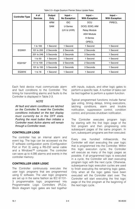
each field device must communicate alarm and fault conditions to the Controller. the timing for transmitting alarms and faults to the Controller is displayed in table 2-3.
noTe
All fault and alarm conditions are latched on the Controller. To reset the Controller, conditions indicated on the text display must currently be in the oFF state. Pushing the reset button then initiates a Controller reset. Active alarms will remain through a Controller reset.
CONTROLLER LOGS
the controller has an internal alarm and event log. the logs can be accessed via the s³ software configuration ports (Configuration Port or Port 3) using a rs-232 serial cable and a Windows™ computer. the controller can save up to 4,095 alarms and events in the controller memory.
CONTROLLER USER LOGIC
the Controller continuously executes the user logic programs that are programmed using s³ software. the user logic programs are set up in the same fashion as IeC 61131-3 programmable logic programmed into Programmable logic Controllers (PlCs). Block diagram logic gates are tied together
with inputs, outputs, and other logic gates to perform a specific task. A number of tasks can be tied together to perform a system function.
typical programmed functions include flame/gas voting, timing delays, timing executions, latching conditions, alarm and trouble notification, suppression control, condition control, and process shutdown notification.
the Controller executes program logic by starting with the first logic page of the first program and then progressing onto subsequent pages of the same program. In turn, subsequent programs are then executed.
every one hundred milliseconds, the Controller will start executing the user logic that is programmed into the Controller. Within this logic execution cycle, the Controller will execute as many of the logic pages as possible. If all programmed logic is executed in a cycle, the Controller will start executing program logic with the next cycle. Otherwise, subsequence logic execution cycles are used to finish executing the remaining logic gates. Only when all the logic gates have been executed will the Controller start over. the Controller will start executing the first logic page of the first program at the beginning of the next logic cycle.
Controller Type# of
DevicesOutput Only
Input – No Exception
Input – With Exception
Input – With Exception
ARM
SAM
IDC
U-Series
(UV & UVIR)
DCU
DCIO, EDIO, AIM
Relay Module
ASH Module
X-Series
OPECL
PIRECL
EQ3001
1 to 100 1 Second 1 Second 1 Second 1 Second
101 to 200 2 Seconds 2 Seconds 2 Seconds 1 Second
201 to 246 5 Seconds 2 Seconds 3 Seconds 1 Second
EQ3150*
1 to 50 1 Second 1 Second 1 Second 1 Second
51 to 100 2 Seconds 2 Seconds 2 Seconds 1 Second
101 to 150 5 Seconds 2 Seconds 3 Seconds 1 Second
EQ3016 1 to 16 1 Second 1 Second 1 Second 1 Second
Table 2-3—Eagle Quantum Premier Status Update Rates
95-85332-516.1
COMMUNICATION NETWORK FAULT OPERATION
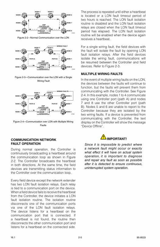
During normal operation, the Controller is continuously broadcasting a heartbeat around the communication loop as shown in Figure 2-2. the Controller broadcasts the heartbeat in both directions. At the same time, the field devices are transmitting status information to the Controller over the communication loop.
every field device except the network extender has two lON fault isolation relays. each relay is tied to a communication port on the device. When a field device fails to receive the heartbeat from the Controller, the device initiates a lON fault isolation routine. the isolation routine disconnects one of the communication ports via one of the lON fault isolation relays. the device listens for a heartbeat on the communication port that is connected. If a heartbeat is not found, the routine then disconnects the other communication port and listens for a heartbeat on the connected side.
the process is repeated until either a heartbeat is located or a lON fault timeout period of two hours is reached. the lON fault isolation routine is disabled and the lON fault isolation relays are closed when the lON fault timeout period has elapsed. the lON fault isolation routine will be enabled when the device again receives a heartbeat.
For a single wiring fault, the field devices with the fault will isolate the fault by opening lON fault isolation relays. After the field devices isolate the wiring fault, communications will be resumed between the Controller and field devices. refer to Figure 2-3.
MULTIPLE WIRING FAULTS
In the event of multiple wiring faults on the lON, the devices between the faults will continue to function, but the faults will prevent them from communicating with the Controller. see Figure 2-4. In this example, nodes 1 to 4 communicate using one Controller port (path A) and nodes 7 and 8 use the other Controller port (path B). Nodes 5 and 6 are unable to report to the Controller because they are isolated by the two wiring faults. If a device is prevented from communicating with the Controller, the text display on the Controller will show the message “Device Offline”.
IMPORTANT!
Since it is impossible to predict where a network fault might occur or exactly what effect it will have on actual system operation, it is important to diagnose and repair any fault as soon as possible after it is detected to ensure continuous, uninterrupted system operation.
Figure 2-3—Communication over the LON with a Single
Wiring Fault
Figure 2-4—Communication over LON with Multiple Wiring
Faults
D1851
NODE 1 NODE 8
NODE 3 NODE 6
NODE 2 NODE 7
NODE 4 NODE 5
EQPCONTROLLER
EAGLE QUANTUM PREMIERSafety System Controller
Fire Alarm Inhibit Power
SuprHigh Gas
Trouble
Cntrl Flt
Lon FaultLow Gas Ack Silence
Out Inhibit
Eagle Quantum Premier
Time & Date
Cancel Enter Next Previous Reset Acknowledge Silence
DET-TRONICS®
D1852
NODE 1 NODE 8
NODE 3 NODE 6
NODE 2 NODE 7
NODE 4 NODE 5
PATH A PATH B
WIRING FAULT
EQPCONTROLLER
EAGLE QUANTUM PREMIERSafety System Controller
Fire Alarm Inhibit Power
SuprHigh Gas
Trouble
Cntrl Flt
Lon FaultLow Gas Ack Silence
Out Inhibit
Eagle Quantum Premier
Time & Date
Cancel Enter Next Previous Reset Acknowledge Silence
DET-TRONICS®
D1853
NODE 1 NODE 8
NODE 3 NODE 6
NODE 2 NODE 7
NODE 4 NODE 5
PATH A PATH B
WIRING FAULTS
EQPCONTROLLER
EAGLE QUANTUM PREMIERSafety System Controller
Fire Alarm Inhibit Power
SuprHigh Gas
Trouble
Cntrl Flt
Lon FaultLow Gas Ack Silence
Out Inhibit
Eagle Quantum Premier
Time & Date
Cancel Enter Next Previous Reset Acknowledge Silence
DET-TRONICS®
Figure 2-2—Normal Communication over the LON
2-6 95-853316.1
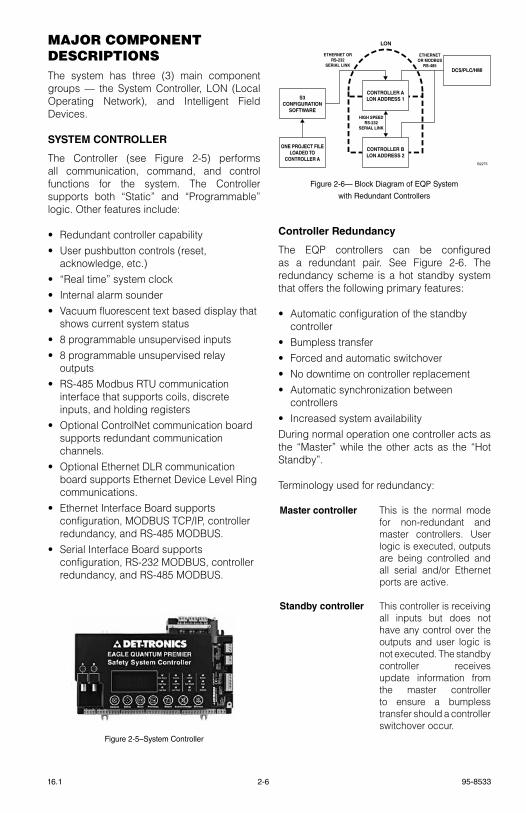
MAJor coMponent DeScrIptIonSthe system has three (3) main component groups — the system Controller, lON (local Operating Network), and Intelligent Field Devices.
SYSTEM CONTROLLER
the Controller (see Figure 2-5) performs all communication, command, and control functions for the system. the Controller supports both “static” and “Programmable” logic. Other features include:
• redundant controller capability• User pushbutton controls (reset,
acknowledge, etc.)• “real time” system clock• Internal alarm sounder• vacuum fluorescent text based display that
shows current system status• 8 programmable unsupervised inputs• 8 programmable unsupervised relay
outputs• rs-485 Modbus rtU communication
interface that supports coils, discrete inputs, and holding registers
• Optional ControlNet communication board supports redundant communication channels.
• Optional ethernet Dlr communication board supports ethernet Device level ring communications.
• ethernet Interface Board supports configuration, MODBUs tCP/IP, controller redundancy, and rs-485 MODBUs.
• serial Interface Board supports configuration, rs-232 MODBUs, controller redundancy, and rs-485 MODBUs.
Controller Redundancy
the eQP controllers can be configured as a redundant pair. see Figure 2-6. the redundancy scheme is a hot standby system that offers the following primary features:
• Automatic configuration of the standby controller
• Bumpless transfer• Forced and automatic switchover• No downtime on controller replacement• Automatic synchronization between
controllers• Increased system availabilityDuring normal operation one controller acts as the “Master” while the other acts as the “Hot standby”.
terminology used for redundancy:
Master controller this is the normal mode for non-redundant and master controllers. User logic is executed, outputs are being controlled and all serial and/or ethernet ports are active.
Standby controller this controller is receiving all inputs but does not have any control over the outputs and user logic is not executed. the standby controller receives update information from the master controller to ensure a bumpless transfer should a controller switchover occur.
LON
S3CONFIGURATION
SOFTWARE
ONE PROJECT FILELOADED TO
CONTROLLER A
CONTROLLER ALON ADDRESS 1
CONTROLLER BLON ADDRESS 2
DCS/PLC/HMI
HIGH SPEEDRS-232
SERIAL LINK
ETHERNET ORRS-232
SERIAL LINK
ETHERNETOR MODBUS
RS-485
B2275
Figure 2-6— Block Diagram of EQP System
with Redundant Controllers
Figure 2-5–System Controller
95-85332-716.1
Primary controller the controller assigned address 1.
Secondary controller the controller assigned address 2.
Bumpless transfer During a controller switchover no change in output will occur due to the switchover.
Ethernet Interface Board
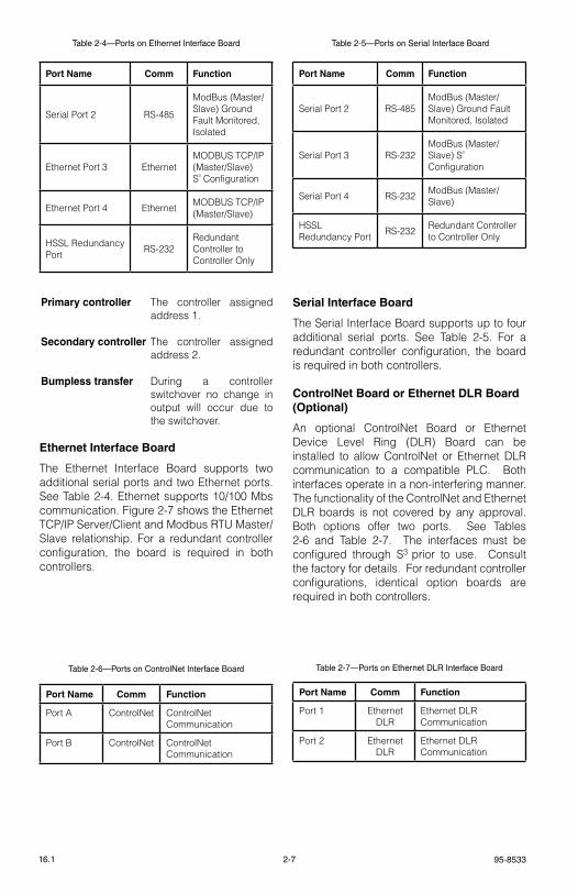
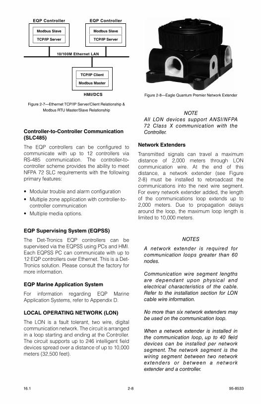
the ethernet Interface Board supports two additional serial ports and two ethernet ports. see table 2-4. ethernet supports 10/100 Mbs communication. Figure 2-7 shows the ethernet tCP/IP server/Client and Modbus rtU Master/slave relationship. For a redundant controller configuration, the board is required in both controllers.
Serial Interface Board
the serial Interface Board supports up to four additional serial ports. see table 2-5. For a redundant controller configuration, the board is required in both controllers.
ControlNet Board or Ethernet DLR Board (Optional)
An optional ControlNet Board or ethernet Device level ring (Dlr) Board can be installed to allow ControlNet or ethernet Dlr communication to a compatible PlC. Both interfaces operate in a non-interfering manner. the functionality of the ControlNet and ethernet Dlr boards is not covered by any approval. Both options offer two ports. see tables 2-6 and table 2-7. the interfaces must be configured through s3 prior to use. Consult the factory for details. For redundant controller configurations, identical option boards are required in both controllers.
Table 2-6—Ports on ControlNet Interface Board
Port Name Comm Function
Port A ControlNet ControlNet Communication
Port B ControlNet ControlNet Communication
Table 2-7—Ports on Ethernet DLR Interface Board
Port Name Comm Function
Port 1 ethernet Dlr
ethernet Dlr Communication
Port 2 ethernet Dlr
ethernet Dlr Communication
Table 2-4—Ports on Ethernet Interface Board
Port Name Comm Function
serial Port 2 rs-485
ModBus (Master/slave) ground Fault Monitored, Isolated
ethernet Port 3 ethernetMODBUs tCP/IP (Master/slave) s³ Configuration
ethernet Port 4 ethernet MODBUs tCP/IP (Master/slave)
Hssl redundancy Port rs-232
redundant Controller to Controller Only
Table 2-5—Ports on Serial Interface Board
Port Name Comm Function
serial Port 2 rs-485ModBus (Master/slave) ground Fault Monitored, Isolated
serial Port 3 rs-232ModBus (Master/slave) s³ Configuration
serial Port 4 rs-232 ModBus (Master/slave)
Hssl redundancy Port rs-232 redundant Controller
to Controller Only
2-8 95-853316.1
Controller-to-Controller Communication (SLC485)
the eQP controllers can be configured to communicate with up to 12 controllers via rs-485 communication. the controller-to-controller scheme provides the ability to meet NFPA 72 slC requirements with the following primary features:
• Modular trouble and alarm configuration• Multiple zone application with controller-to-
controller communication• Multiple media options.
EQP Supervising System (EQPSS)
the Det-tronics eQP controllers can be supervised via the eQPss using PCs and HMI. each eQPss PC can communicate with up to 12 eQP controllers over ethernet. this is a Det-tronics solution. Please consult the factory for more information.
EQP Marine Application System
For information regarding eQP Marine Application systems, refer to Appendix D.
LOCAL OPERATING NETWORK (LON)
the lON is a fault tolerant, two wire, digital communication network. the circuit is arranged in a loop starting and ending at the Controller. the circuit supports up to 246 intelligent field devices spread over a distance of up to 10,000 meters (32,500 feet).
noTeAll Lon devices support AnSI/nFPA 72 Class X communication with the Controller.
Network Extenders
transmitted signals can travel a maximum distance of 2,000 meters through lON communication wire. At the end of this distance, a network extender (see Figure 2-8) must be installed to rebroadcast the communications into the next wire segment. For every network extender added, the length of the communications loop extends up to 2,000 meters. Due to propagation delays around the loop, the maximum loop length is limited to 10,000 meters.
noTeS
A network extender is required for communication loops greater than 60 nodes.
Communication wire segment lengths are dependant upon physical and electrical characteristics of the cable. Refer to the installation section for Lon cable wire information.
no more than six network extenders may be used on the communication loop.
When a network extender is installed in the communication loop, up to 40 field devices can be installed per network segment. The network segment is the wiring segment between two network extenders or between a network extender and a controller.
Modbus Slave
TCP/IP Server
Modbus Slave
TCP/IP Server
TCP/IP Client
Modbus Master
10/100M Ethernet LAN
EQP Controller EQP Controller
HMI/DCS
Figure 2-7—Ethernet TCP/IP Server/Client Relationship &
Modbus RTU Master/Slave Relationship
Figure 2-8—Eagle Quantum Premier Network Extender

95-85332-916.1
EQ21xxPS Series Power Supplies and EQ2100PSM Power Supply Monitor
the Power supply, Power supply Monitor, and backup batteries are used to provide power to the system. the power supply monitor communicates trouble conditions to the Controller. Monitored status conditions include: power supply failure, loss of AC power, loss of battery power, power ground fault, AC and DC voltage (hi/low level), and backup battery current charge levels.
the Power supply provides main and backup power to the eQP system. the device includes many features such as voltage regulation, high efficiency, and high power factor.
An equalize switch is located on the front panel of the charger for manual activation, or a multi-mode electronic timer can be used for automatic activation. steady state output voltage remains within +/– 1/2% of the setting from no load to full load for AC input voltages within +/– 10% of the nominal input voltage.
EQP21XXPS(–X) Power Supplies and EQP2410PS(–P) Converter
the Power supplies and Converter provide main and backup power to the eQP system in ordinary and marine applications. refer to section 3 of this manual for complete information.
EQ2220GFM Ground Fault Monitor
the eQ2220gFM ground Fault Monitor (see Figure 2-9) provides ground fault monitoring in a system that includes a floating 24 vdc power source. the device detects ground fault conditions on +/– power and all secondary I/O circuits. A positive or negative ground fault condition is indicated immediately by local leDs, and by a relay contact after a 10 second time delay. the ground fault monitor is intended to be mounted in the same enclosure as the controller.
FIELD DEVICES
Flame Detectors
For flame detector installation, operation, maintenance, specifications and ordering information, refer to table 2-8.
For information regarding UsCg Approval of the X3301 Flame Detector, refer to Appendix D.
noTe
existing eagle Quantum field devices such as eQ22xxUV and eQ22xxUVIR are supported by the eagle Quantum Premier system (not FM Approved).
EQ3730EDIO Enhanced Discrete Input/Output Module
the 8 Channel eDIO Module (see Figure 2-10) expands the Input and Output capability of the eagle Quantum Premier system.
the unit is designed to provide continuous and automated fire/gas protection, while ensuring system operation through continuous supervision of system Inputs/Outputs.
Figure 2-9—Ground Fault Monitor
Table 2-8—Flame Detector Manuals
Detector Manual Number
X3301 95-8527
X3301A 95-8527 & 95-8534
X3302 95-8576
X5200 95-8546
X2200 95-8549
X9800 95-8554
UVHT 95-8570

2-10 95-853316.1
the eDIO module provides eight channels of configurable input or output points that can be programmed for supervised or unsupervised operation. each input point can accept fire detection devices such as heat, smoke, or unitized flame detectors. each output point can be configured for signaling or releasing output operation. each channel on the module is provided with individual indicators for active and fault conditions.
IMPORTANT
For Class A wiring, two input/output channels are combined, thereby supporting up to four input/output circuits.
noTe
An input must be active for at least 750 milliseconds in order to be recognized.
the eDIO module can be mounted directly to a panel, or it can be DIN rail mounted. system status can be determined using the trouble-shooting procedures, eagle Quantum safety system software (s³) and the status indicators on the module.
refer to the enhanced Discrete Input/Output Module specification Data sheet (form number 90-1189) for additional information.
EQ3700 8 Channel DCIO Module
the 8 Channel Discrete Input/Output (DCIO) Module (see Figure 2-11) consists of eight individually configured channels. each channel is configured as either an input or output with the appropriate wiring supervision. Wiring supervision includes none, open circuits, and "open and short" circuits. In addition to defining the type of supervision, an input channel is also configured to generate the appropriate static logic alarm message to the controller.
noTe
nFPA 72 requires wire supervision se lect ion for f i re detect ion and no t i f i ca t ion dev ices ( IDC, nAC, supervisory and releasing devices).
Heat, smoke, or unitized flame detectors can be wired into channels defined as inputs. Horns, strobes/beacons, and solenoids can be wired into channels defined as outputs.
noTe
The DCIo outputs on ly suppor t equipment that operates on 24 vdc (not to exceed 2 amperes per channel).
the DCIO has two device status leDs, as well as two leDs for each channel. On the device level, one green leD indicates power, while the other amber leD indicates a lON CPU fault. For each channel, one red leD indicates channel activation and the other amber leD indicates a fault condition when wiring supervision is defined for the channel.
refer to the DCIO specification Data sheet (form number 90-1149) for additional information.
Figure 2-11—DCIO ModuleFigure 2-10—Enhanced Discrete
Input/Output Module

95-85332-1116.1
EQ3720 8 Channel Relay Module
the 8 Channel relay Module (see Figure 2-12) consists of eight individually configured output channels.
noTe
The re lay module only supports equipment that operates on 24 vdc (not to exceed 2 amperes) at each output channel.
the relay module has two leDs for the device and two leDs for each channel. On the device level, one green leD indicates power, while the other amber leD indicates a lON CPU fault. For each channel, one red leD indicates channel activation and the other amber leD indicates that the module operating voltage is low or that the module has not been configured (all eight channel leDs blink).
refer to the relay Module specification Data sheet (form number 90-1181) for additional information.
EQ3710AIM Analog Input Module
the 8 Channel Analog Input Module (see Figure 2-13) provides a means of connecting devices with a calibrated 4-20 mA output signal to the eagle Quantum Premier system.
the Analog Input Module (AIM) provides 8 configurable channels that can be set for either combustible gas mode or universal mode. the combustible gas mode provides a number of automatically programmed settings, and alarm thresholds that are limited to approval body requirements. the universal mode is used for generic devices where control over all configuration parameters is required. All devices must provided their own calibration facilities.
For fire detector 4-20 mA inputs, the Analog Input Module (AIM) is certified for use as an NFPA 72 Class B Approved input.
refer to the Analog Input Module specification Data sheet (form number 90-1183) for additional information.
Figure 2-12—Eight Channel Relay Module Figure 2-13—Eight Channel Analog Input Module

2-12 95-853316.1
EQ3750ASH Addressable Smoke & Heat Module
the Addressable smoke and Heat (AsH) Module (see Figure 2-14) is an interface device designed to provide continuous and automated fire protection for the eQP system.
the AsH module is located directly on the lON of the eQP system, with a loop of up to 64 addressable devices tied into the AsH module. this allows all of the flame, gas, and addressable smoke and heat detectors to run on one system, enabling the eQP controller to annunciate a fire alarm from either its own lON based I/O, or from the connected addressable smoke and heat detection loops. the eQP controller can support up to 10 AsH modules.
the AsH module can support a variety of Apollo Discovery and XP95 devices, including smoke, heat, manual call, sounders, beacons and I/O modules. the addressable devices are configured individually via the s³ software.
to ensure reliable system operation, the AsH module continuously monitors its input and output circuits for opens and short circuit conditions.
During normal operation, the AsH module continuously checks the loop for fault conditions and executes user defined programmed logic that coordinates the control of the field devices. the AsH module reports any device based fault and alarm conditions to the eQP controller.
the eQP Controller continuously monitors the status of the AsH module, as well as the status of each device connected to the AsH module. AsH module alarm and fault status conditions are logged in the eQP controller.
system status can be determined using s³ software or the status indicators on the AsH module, where leDs annunciate power on, faults, or an active device on the loop.
refer to the AsH module instruction manual (form number 95-8654) for additional information.
Figure 2-14—Addressable Smoke & Heat Module

95-85332-1316.1
EQ25xxARM Agent Release Modulethe eQ25xxArM series Agent release Module (ArM) (see Figure 2-15) provides agent release or deluge pre-action capability. the device is controlled by programmable logic in the Controller. time delay, abort and manual release sequences allow the device output to be programmed for use in unique applications.
the device is field programmed to operate in one of the following modes:timed– Output is activated for a field selectable duration from 1 to 65,000 seconds.Continuous– Output latches until reset.Non-latching– Output follows the input.
the device can monitor and control two output devices (24 vdc rated) that are programmed and energized together. the release circuits are compatible with a variety of solenoid or initiator based suppression systems.
the release circuit is supervised for open circuit conditions. If a trouble condition occurs (open circuit or solenoid supply voltage less than 19 volts), it will be indicated at the Controller. each output is rated at 2 amperes and auxiliary input terminals are provided for additional 24 vdc output power where needed.
noTe
For deluge and pre-action applications, the input voltage to the ARM or DCIo must be 21 VDC minimum with connection to any solenoid listed in Table 2-9 or 2-10. Wiring must be in accordance with the listed maximum wiring lengths.
refer to the eQ25xxArM specification Data sheet (form number 90-1128) for additional information
Figure 2-15—Agent Release Module
Table 2-10—Maximum Wiring Length for FM Approved Solenoids for Deluge and Pre-Action Applications
Table 2-9—Solenoid Compatibility with Agent
Release Module for Deluge and Pre-Action Applications
FM Group Device
B ASCO T8210A107
D ASCO 8210G207
E Skinner 73218BN4UNLVNOC111C2
F Skinner 73212BN4TNLVNOC322C2
G Skinner 71395SN2ENJ1NOH111C2
H Viking 11601
Solenoids Maximum Wire Length in Feet (Meters)
FM Solenoid Group Manufacturer Model 12 AWG 14 AWG 16 AWG 18 AWG
B AsCO t8210A107 183 (56) 115 (35) 72 (22) 46 (14)
D AsCO 8210g207 314 (96) 198 (60) 124 (38) 78 (24)
e skinner 73218BN4UNlvNOC111C2 331(101) 208 (63) 131 (40) 82 (25)
F skinner 73212BN4tNlvNOC322C2 130 (40) 82 (25) 51 (16) 32 (10)
g skinner 71395sN2eNJ1NOH111C2 331 (101) 208 (63) 131 (40) 82 (25)
H viking 11601 180 (55) 110 (34) 70 (21) 45 (14)

2-14 95-853316.1
EQ25xxSAM Signal Audible Module
the eQ25xxsAM series signal Audible Module (sAM) (see Figure 2-16) provides two indicating circuits for controlling Ul listed 24 vdc polarized audible/visual indicating appliances.
the device is located on the lON and is controlled by programmable logic in the Controller.
each output circuit is independently programmable to allow notification of separate events. each output can be individually activated for any one of the following pre-defined outputs:
1. Continuous2. 60 beats per minute3. 120 beats per minute4. temporal pattern.
Device outputs operate in the reverse polarity manner when activated. each output is rated at 2 amperes. Auxiliary power input terminals are provided for additional 24 vdc signaling power where required. the output circuits are supervised for open and short circuit conditions. If a wiring fault occurs, a trouble condition will be indicated at the Controller.
refer to the eQ25xxsAM specification Data sheet (form number 90-1129) for additional information
Figure 2-16—Signal Audible Module
EQ22xxIDC Series Initiating Device Circuit (IDC)
there are three IDC models available (see Figure 2-17):
the EQ22xxIDC allows discrete inputs from smoke/heat detectors, manual call stations or other contact devices.
the IDC accepts two dry contact inputs for use with devices such as relays, pushbuttons, key switches, etc. the IDC supports ANsI/NFPA 72 Class B supervised input circuits
each circuit requires its own end of line (eOl) resistor for monitoring circuit continuity. Nominal resistance of the resistor is 10 k ohms.
the EQ22xxIDCGF Initiating Device Circuit ground Fault Monitor (IDCgF) responds to the presence of a ground fault within the power circuitry of the system. It provides an unsupervised dry contact input and ground fault monitoring circuitry for indicating a power supply trouble condition. It is intended for use with a third party power supply.
the EQ22xxIDCSC Initiating Device Circuit short Circuit (IDCsC) is similar to the IDC, but supports supervision per eN 54 for european installations.
refer to the eQ22xxIDC specification Data sheet (form number 90-1121) for additional information.
noTe
Input types (e.g. fire alarm, trouble, and gas alarms) are configurable through Det-Tronics Safety System Software (S³).
Figure 2-17—Initiating Device Circuit

95-85332-1516.1
EQ22xxDCU and EQ22xxDCUEXDigital Communication Units
the eQ22xxDCU Digital Communication Unit (DCU) is an analog signal input device that accepts a 4 to 20 milliampere signal. the device is typically connected to gas detectors, where the analog signal represents the gas concentration.
Calibration of the DCU involves a non-intrusive procedure that can be performed by one person at the device without declassifying the area.
the device supports two alarm setpoints that are defined as part of the device’s configuration setup. When detecting combustible gases, the alarm setpoints represent low and high gas alarm levels. When detecting oxygen, the alarms represent the range for the acceptable oxygen level. If oxygen drops below the alarm range, a low alarm is generated by the device.
PointWatch/DuctWatch Ir gas detector as well as electrochemical sensors (hydrogen sulfide, carbon monoxide, chlorine, sulfur dioxide, and nitrogen dioxide) are examples of devices that can be connected to the DCU.
noTe
A catalytic sensor can be connected to a DCU through a transmitter, which converts the millivolt signal to a 4 to 20 milliampere signal.
the eQ22xxDCUeX is a specialized version of the DCU that contains a transmitter for connection to a Det-tronics Model Cgs catalytic combustible gas sensor.
refer to the eQ22xxDCU specification Data sheet (form number 90-1118) for additional information.
PIRECL PointWatch Eclipse
the Pointwatch eclipse® Model PIreCl is a diffusion-based, point-type infrared gas detector that provides continuous monitoring of combustible hydrocarbon gas concentrations in the range of 0 to 100% lFl.
the lON supervision meets signaling line Circuit (Class X) requirements per NFPA72: 2010 for the Model PIreCl.
For PIreCl installation, operation, maintenance, specifications and ordering information, refer to form number 95-8526.
noTe
The low alarm range for the eQP PIReCL is 5-40% LFL (the standard PIReCL is 5-60% LFL).
For information regarding UsCg Approval of the PIreCl Detector, refer to Appendix D.
OPECL Open Path Eclipse
the Open Path eclipse™ Model OPeCl is an open path infrared gas detection system that provides continuous monitoring of combustible hydrocarbon gas concentrations in the range of 0 to 5 lFl-meters, over a distance of 5 to 120 meters.
the lON supervision meets signaling line Circuit (Class X) requirements per NFPA72: 2010 for the Model OPeCl.
For OPeCl installation, operation, maintenance, specifications and ordering information, refer to form number 95-8556.
UD10 DCU Emulator
the Flexvu® Model UD10 DCU emulator (UD10-DCU) is designed for applications that require a gas detector with digital readout of detected gas levels. Its lON interface board makes the UD10-DCU compatible with eagle Quantum Premier systems by digitizing the 4-20 mA analog signal from the attached sensor/transmitter and transmitting the value as a process variable over the lON to the eQP controller. the UD10-DCU is designed for use with most currently available Det-tronics gas detectors.
For a list of compatible gas detectors, as well as information regarding installation, operation, maintenance, specifications and ordering information, refer to form number 95-8656.

3-1 95-853316.1
Section 3Installation
noTe
For specific information regarding systems meeting en54 standards, refer to the eQ5400 Series operation manual 95-8642.
SAFety SySteM DeSIgn reQUIreMentSMany factors need to be considered when determining proper eQP system design. the following paragraphs will discuss these factors and other issues useful in designing, installing and configuring the eagle Quantum Premier system.
IDENTIFYING THE AREA OF PROTECTION
In order for the system to provide optimum coverage and protection, it is critical to properly define the required “Area of Protection” (total area being monitored by the system). the area of protection should include all hazard sources requiring monitoring, as well as suitable locations for mounting detection, extinguishing, notification, and manual devices. In order to accurately define the area of protection and provide maximum protection, all potential “real” and “False” hazard sources must be identified. the number and location of real Hazards determines the extent of the area of protection, and impacts all subsequent design decisions.
WARNING!
When drilling through surfaces in the process of mounting equipment, verify that the location is free of electrical wiring and electrical components.
IDENTIFYING WIRING, NETWORK (LON), AND SYSTEM POWER REQUIREMENTS
General Wiring Requirements
WARNING!
Do noT open any junction box or device enclosure when power is applied without first de-classifying the hazardous area.
CAUTION!
Any deviation from the manufacturer’s recommended wiring practices can compromise system operation and effectiveness. ALWAYS consult the factory if different wire types or methods are being considered.
noTe
All field wiring must be marked per nFPA 70 Article 760.
noTe
Specific installation requirements may differ depending on local installation practices and compliance with third party certifications. For local installation practices, consult the local authority having jurisdiction. For compliance with third party certifications, consult the appropriate appendix in this manual for additional installation requirements.
Power Wiring
IMPORTANT!
For deluge and pre-action applications, input voltage to the DCIo or ARM must be 21 vdc minimum to ensure proper operation of the connected output device.
IMPORTANT
To ensure proper operation of field devices, the voltage input to the device (measured at the device) must be within the range indicated for that device in the “Specifications” section of this manual (18 Vdc minimum).
System Wiring (ATEX and IECEx)
For the interconnection of the modules within the eQP system, use fixed installed wiring. (For correct wiring size and type for a specific device, refer to the appropriate section in this manual.)
For ambient temperatures below –10°C and above +60°C, use field wiring suitable for both minimum and maximum ambient temperatures.
95-85333-216.1
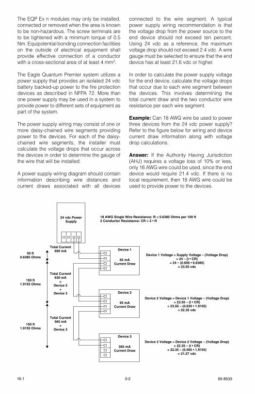
the eQP ex n modules may only be installed, connected or removed when the area is known to be non-hazardous. the screw terminals are to be tightened with a minimum torque of 0.5 Nm. equipotential bonding connection facilities on the outside of electrical equipment shall provide effective connection of a conductor with a cross-sectional area of at least 4 mm2.
the eagle Quantum Premier system utilizes a power supply that provides an isolated 24 vdc battery backed-up power to the fire protection devices as described in NFPA 72. More than one power supply may be used in a system to provide power to different sets of equipment as part of the system.
the power supply wiring may consist of one or more daisy-chained wire segments providing power to the devices. For each of the daisy-chained wire segments, the installer must calculate the voltage drops that occur across the devices in order to determine the gauge of the wire that will be installed.
A power supply wiring diagram should contain information describing wire distances and current draws associated with all devices
connected to the wire segment. A typical power supply wiring recommendation is that the voltage drop from the power source to the end device should not exceed ten percent. Using 24 vdc as a reference, the maximum voltage drop should not exceed 2.4 vdc. A wire gauge must be selected to ensure that the end device has at least 21.6 vdc or higher.
In order to calculate the power supply voltage for the end device, calculate the voltage drops that occur due to each wire segment between the devices. this involves determining the total current draw and the two conductor wire resistance per each wire segment.
Example: Can 18 AWg wire be used to power three devices from the 24 vdc power supply? refer to the figure below for wiring and device current draw information along with voltage drop calculations.
Answer: If the Authority Having Jurisdiction (AHJ) requires a voltage loss of 10% or less, only 16 AWg wire could be used, since the end device would require 21.4 vdc. If there is no local requirement, then 18 AWg wire could be used to provide power to the devices.
Device 1
65 mACurrent Draw
Device 2
65 mACurrent Draw
Device 3
565 mACurrent Draw
24 vdc PowerSupply
18 AWG Single Wire Resistance: R = 0.6385 Ohms per 100 ft2 Conductor Resistance: CR = 2 • R
Device 1 Voltage = Supply Voltage – (Voltage Drop)= 24 – (I • CR)
= 24 – (0.695 • 0.6385)= 23.55 vdc
Device 2 Voltage = Device 1 Voltage – (Voltage Drop)= 23.55 – (I • CR)
= 23.55 – (0.630 • 1.9155)= 22.35 vdc
Device 3 Voltage = Device 2 Voltage – (Voltage Drop)= 22.35 – (I • CR)
= 22.35 – (0.565 • 1.9155)= 21.27 vdc
50 ft0.6385 Ohms
150 ft1.9155 Ohms
150 ft1.9155 Ohms
Total Current695 mA
Total Current630 mA
=Device 2
+Device 3
Total Current565 mA
=Device 3
3-3 95-853316.1
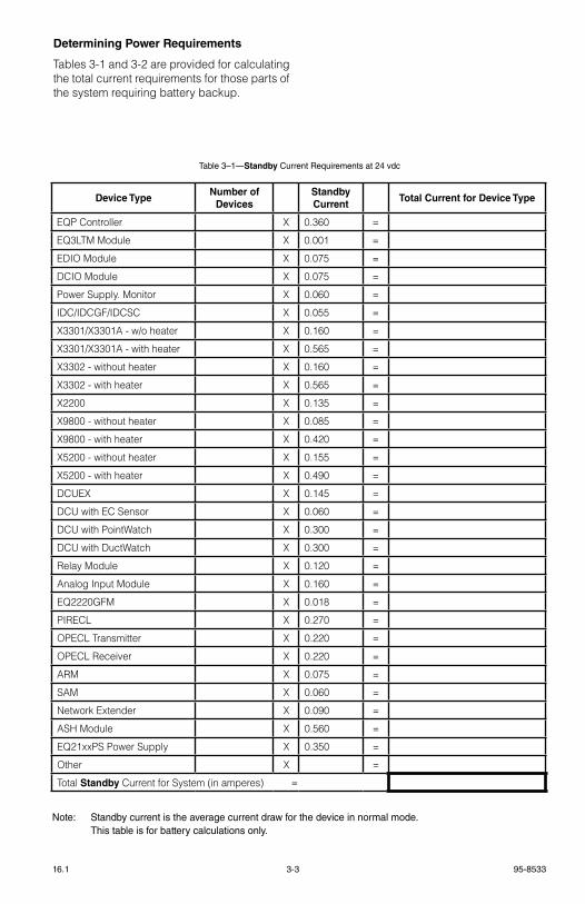
Determining Power Requirements
tables 3-1 and 3-2 are provided for calculating the total current requirements for those parts of the system requiring battery backup.
Table 3–1—Standby Current Requirements at 24 vdc
Note: Standby current is the average current draw for the device in normal mode. This table is for battery calculations only.
Device TypeNumber of
DevicesStandby Current
Total Current for Device Type
eQP Controller X 0.360 =
eQ3ltM Module X 0.001 =
eDIO Module X 0.075 =
DCIO Module X 0.075 =
Power supply. Monitor X 0.060 =
IDC/IDCgF/IDCsC X 0.055 =
X3301/X3301A - w/o heater X 0.160 =
X3301/X3301A - with heater X 0.565 =
X3302 - without heater X 0.160 =
X3302 - with heater X 0.565 =
X2200 X 0.135 =
X9800 - without heater X 0.085 =
X9800 - with heater X 0.420 =
X5200 - without heater X 0.155 =
X5200 - with heater X 0.490 =
DCUeX X 0.145 =
DCU with eC sensor X 0.060 =
DCU with PointWatch X 0.300 =
DCU with DuctWatch X 0.300 =
relay Module X 0.120 =
Analog Input Module X 0.160 =
eQ2220gFM X 0.018 =
PIreCl X 0.270 =
OPeCl transmitter X 0.220 =
OPeCl receiver X 0.220 =
ArM X 0.075 =
sAM X 0.060 =
Network extender X 0.090 =
AsH Module X 0.560 =
eQ21xxPs Power supply X 0.350 =
Other X =
total Standby Current for system (in amperes) =
95-85333-416.1
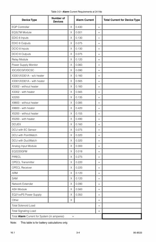
Table 3-2—Alarm Current Requirements at 24 Vdc
Device TypeNumber of
DevicesAlarm Current Total Current for Device Type
eQP Controller X 0.430 =
eQ3ltM Module X 0.001 =
eDIO 8 Inputs X 0.130 =
eDIO 8 Outputs X 0.075 =
DCIO 8 Inputs X 0.130 =
DCIO 8 Outputs X 0.075 =
relay Module X 0.120 =
Power supply Monitor X 0.060 =
IDC/IDCgF/IDCsC X 0.090 =
X3301/X3301A - w/o heater X 0.160 =
X3301/X3301A - with heater X 0.565 =
X3302 - without heater X 0.160 =
X3302 - with heater X 0.565 =
X2200 X 0.135 =
X9800 - without heater X 0.085 =
X9800 - with heater X 0.420 =
X5200 - without heater X 0.155 =
X5200 - with heater X 0.490 =
DCUeX X 0.160 =
DCU with eC sensor X 0.075 =
DCU with PointWatch X 0.320 =
DCU with DuctWatch X 0.320 =
Analog Input Module X 0.300 =
eQ2220gFM X 0.018 =
PIreCl X 0.275 =
OPeCl transmitter X 0.220 =
OPeCl receiver X 0.220 =
ArM X 0.120 =
sAM X 0.120 =
Network extender X 0.090 =
AsH Module X 0.560 =
eQ21xxPs Power supply X 0.350 =
Other X =
total solenoid load +
total signaling load +
total Alarm Current for system (in amperes) =
Note: This table is for battery calculations only.

3-5 95-853316.1
EQ211xPS, EQ213xPS and EQ217xPS Power Supplies
refer to table 3-3A for Power supply ratings.
Backup Battery
refer to table 3-4 or 3-5 to calculate the minimum size of the backup battery (in amp hours). select a sealed lead-acid battery with an adequate amp hour rating.
noTe
Connect two batteries in series for 24 volts. Batteries must be protected from physical damage. The battery installation shall be adequately ventilated.
Battery Charger
Use the following formula to calculate the minimum battery charger size:
MinimumCharge Rate
= Alarm Current + total Amp Hours
48
CAUTION!
Care should be taken when considering the final voltage at the device during AC power loss. With loss of AC power, the device voltage will drop over time as the batteries lose their charge. If extended periods of AC power loss are to be
expected, either consider a heavier wire gauge or specify batteries with higher amp-hour ratings.
EQP21X0PS(–X) Power Supplies
the eQP2110Ps(–P) and eQP2120Ps(–B) Power supplies are used in pairs where the primary source of input supply is connected to one and the secondary source is connected to the other. each power supply may be backed up by another power supply of the same model or by a DC-DC converter (see Figures 3-23A, B and C for available configurations). A maximum of eight power supplies operated in parallel can be connected to each input supply. Both the primary and secondary sets must be individually capable of operating the system without the other supply. the secondary source is required to be continuously powered.
the use of these supplies is based upon acceptance of the local AHJ of the secure supply system that provides the secondary supply. these supplies must be used in a redundant configuration, where one bank of supplies is fed from the primary source and the other bank from the secondary source. Both primary and secondary supplies shall be continuously available and both rated for a minimum 100% of load.
refer to table 3-3B for power supply ratings.
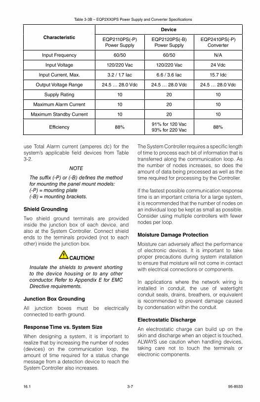
Characteristic
Power Supply
EQ2110PS/EQ2111PS EQ2130PS/EQ2131PS EQ2175PS/EQ2176PS
Input Voltage 120 vac 120/208/240 vac 120/208/240 vac
Input Current 4 Amps 11/6/6 Amps 24/15/12 Amps
Input Frequency 60 Hz – EQ2110PS 60 Hz – EQ2130PS 60 Hz – EQ2175PS
Input Frequency 50 Hz – EQ2111PS 50 Hz – EQ2131PS 50 Hz – EQ2176PS
Supply Rating 10 Amps 30 Amps 75 Amps
Maximum Alarm Current 10 Amps 30 Amps 75 Amps
Maximum Standby Current 3.33 Amps 10 Amps 25 Amps
Recharge Current 6.67 Amps 20 Amps 50 Amps
Minimum Battery Capacity** 40 AmpHours 120 AmpHours 300 AmpHours
Maximum Battery Capacity 100 AmpHours 300 AmpHours 750 AmpHours
Maximum Deluge Standby Current* 1 Amp 3 Amps 7.5 Amps
*Only applies to 90 hour back-up applications.**Use a battery with a maximum charge rate that exceeds 25% of the rating of the power supply.
Table 3-3A—EQ21xxPS Power Supply Specifications

95-85333-616.1
IMPORTANT
The eQP21X0PS(–X) Power Supplies provide eQP System devices with power from input supply 120 to 220 V ac. Use of this power supply does not provide the source of the secondary supply such as secondary source batteries, their supervision or charging, or UPS. Per nFPA 72-2010 requirements, such power supply related requirements must be separately provided for and be accepted by the local Authority Having Jurisdiction (AHJ).
EQP2410PS(–P) Converter
the eQP2410Ps(–P) Converter converts the DC input voltage to an adjustable, controlled and galvanically separated 24 vdc output voltage. the converter is always connected to the secondary source.
Determining Power RequirementsUse of the eQP2110Ps(–P) and eQP2120Ps(–B) Power supplies provides the primary and secondary supplies.
the eQP2410Ps(–P) Converter provides the secondary supply only. It is used in conjunction with the eQP2110Ps(–P) or eQP2120Ps(–B) Power supplies, which serve as the primary supply (see Figures 3-23A, B and C for available configurations). the customer is responsible for providing adequate secondary power supply source needs. the ac input current requirements for eQP2XX0Ps(–X) in relation to eQP system dc current load (power supply output) are calculated using the following formula:
Input Current = [Output Current x Output voltage÷ Input voltage ÷ efficiency] + 0.43 A
Example:[20 Adc x 28 vdc ÷ 120 vac ÷ 0.91] + 0.43 = 5.56 Aac
For standby Current (amperes ac) requirements, use total standby Current (amperes dc) for the system’s applicable field devices from table 3-1.
For Alarm Current (amperes ac) requirements,
Standby Current Standby Time* Standby Amp HoursX =
24 Hours
Alarm Current 5 Minute Alarm Time* Alarm Amp HoursX =
0.083 Hours
Sum of Standby and Alarm Amp Hours =
Multiply by 1.2 (20% Safety Factor) X
Total Battery Amp Hour RequirementT0014B
* FM MINIMUM REQUIREMENT FOR EXTINGUISHING SYSTEMSIS 24 HOURS STANDBY TIME AND 5 MINUTES ALARM TIME.
Table 3-4—Backup Battery Requirements for Automatic Release of Extinguishing Systems Except Deluge
Standby Current Standby Time* Standby Amp HoursX =
90 Hours
Alarm Current 10 Minute Alarm Time* Alarm Amp HoursX =
0.166 Hours
Sum of Standby and Alarm Amp Hours =
Multiply by 1.2 (20% Safety Factor) X
Total Battery Amp Hour RequirementT0040B
* FM MINIMUM REQUIREMENT FOR DELUGE SYSTEMS IS90 HOURS STANDBY TIME AND 10 MINUTES ALARM TIME.
Table 3-5—Backup Battery Requirements for Deluge and Pre-Action Applications
3-7 95-853316.1
use total Alarm current (amperes dc) for the system’s applicable field devices from table 3-2.
noTe
The suffix (-P) or (-B) defines the method for mounting the panel mount models:(-P) = mounting plate(-B) = mounting brackets.
Shield Grounding
two shield ground terminals are provided inside the junction box of each device, and also at the system Controller. Connect shield ends to the terminals provided (not to each other) inside the junction box.
CAUTION!
Insulate the shields to prevent shorting to the device housing or to any other conductor. Refer to Appendix e for eMC Directive requirements.
Junction Box Grounding
All junction boxes must be electrically connected to earth ground.
Response Time vs. System Size
When designing a system, it is important to realize that by increasing the number of nodes (devices) on the communication loop, the amount of time required for a status change message from a detection device to reach the system Controller also increases.
the system Controller requires a specific length of time to process each bit of information that is transferred along the communication loop. As the number of nodes increases, so does the amount of data being processed as well as the time required for processing by the Controller.
If the fastest possible communication response time is an important criteria for a large system, it is recommended that the number of nodes on an individual loop be kept as small as possible. Consider using multiple controllers with fewer nodes per loop.
Moisture Damage Protection
Moisture can adversely affect the performance of electronic devices. It is important to take proper precautions during system installation to ensure that moisture will not come in contact with electrical connections or components.
In applications where the network wiring is installed in conduit, the use of watertight conduit seals, drains, breathers, or equivalent is recommended to prevent damage caused by condensation within the conduit.
Electrostatic Discharge
An electrostatic charge can build up on the skin and discharge when an object is touched. AlWAYs use caution when handling devices, taking care not to touch the terminals or electronic components.
Table 3-3B – EQP2XX0PS Power Supply and Converter Specifications
Characteristic
Device
EQP2110PS(-P)Power Supply
EQP2120PS(-B) Power Supply
EQP2410PS(-P)Converter
Input Frequency 60/50 60/50 N/A
Input Voltage 120/220 Vac 120/220 Vac 24 Vdc
Input Current, Max. 3.2 / 1.7 Iac 6.6 / 3.6 Iac 15.7 Idc
Output Voltage Range 24.5 … 28.0 Vdc 24.5 … 28.0 Vdc 24.5 … 28.0 Vdc
Supply Rating 10 20 10
Maximum Alarm Current 10 20 10
Maximum Standby Current 10 20 10
Efficiency 88%91% for 120 Vac93% for 220 Vac
88%
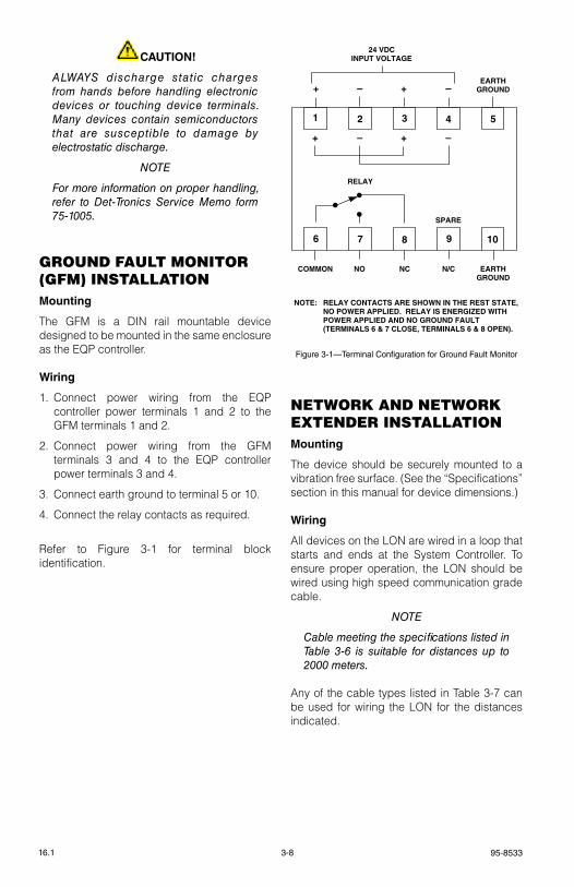
95-85333-816.1
CAUTION!
ALWAYS discharge static charges from hands before handling electronic devices or touching device terminals. Many devices contain semiconductors that are susceptible to damage by electrostatic discharge.
noTe
For more information on proper handling, refer to Det-Tronics Service Memo form 75-1005.
groUnD FAUlt MonItor (gFM) InStAllAtIonMounting
the gFM is a DIN rail mountable device designed to be mounted in the same enclosure as the eQP controller.
Wiring
1. Connect power wiring from the eQP controller power terminals 1 and 2 to the gFM terminals 1 and 2.
2. Connect power wiring from the gFM terminals 3 and 4 to the eQP controller power terminals 3 and 4.
3. Connect earth ground to terminal 5 or 10.
4. Connect the relay contacts as required.
refer to Figure 3-1 for terminal block identification.
netWorK AnD netWorK eXtenDer InStAllAtIonMounting
the device should be securely mounted to a vibration free surface. (see the “specifications” section in this manual for device dimensions.)
Wiring
All devices on the lON are wired in a loop that starts and ends at the system Controller. to ensure proper operation, the lON should be wired using high speed communication grade cable.
noTe
Cable meeting the specifications listed in Table 3-6 is suitable for distances up to 2000 meters.
Any of the cable types listed in table 3-7 can be used for wiring the lON for the distances indicated.
6 7 8 9 10
COMMON NO NC N/C
RELAY
SPARE
1 2 3 4 5
+ +– –
EARTHGROUND
+ +– –EARTH
GROUND
24 VDCINPUT VOLTAGE
NOTE: RELAY CONTACTS ARE SHOWN IN THE REST STATE, NO POWER APPLIED. RELAY IS ENERGIZED WITH POWER APPLIED AND NO GROUND FAULT (TERMINALS 6 & 7 CLOSE, TERMINALS 6 & 8 OPEN).
Figure 3-1—Terminal Configuration for Ground Fault Monitor
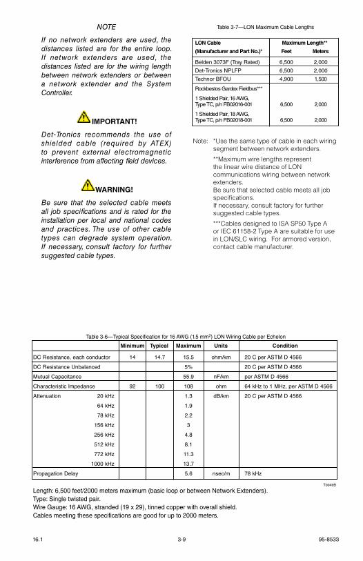
3-9 95-853316.1
noTe
If no network extenders are used, the distances listed are for the entire loop. If network extenders are used, the distances listed are for the wiring length between network extenders or between a network extender and the System Controller.
IMPORTANT!
Det-Tronics recommends the use of shielded cable (required by ATeX) to prevent external electromagnetic interference from affecting field devices.
WARNING!
Be sure that the selected cable meets all job specifications and is rated for the installation per local and national codes and practices. The use of other cable types can degrade system operation. If necessary, consult factory for further suggested cable types.
Table 3-7—LON Maximum Cable Lengths
Note: *Use the same type of cable in each wiring segment between network extenders.
**Maximum wire lengths represent the linear wire distance of lON communications wiring between network extenders.
Be sure that selected cable meets all job specifications.
If necessary, consult factory for further suggested cable types.
***Cables designed to IsA sP50 type A or IeC 61158-2 type A are suitable for use in lON/slC wiring. For armored version, contact cable manufacturer.
Table 3-6—Typical Specification for 16 AWG (1.5 mm2) LON Wiring Cable per Echelon
Minimum Typical Maximum Units Condition
DC Resistance, each conductor 14 14.7 15.5 ohm/km 20 C per ASTM D 4566
DC Resistance Unbalanced 5% 20 C per ASTM D 4566
Mutual Capacitance 55.9 nF/km per ASTM D 4566
Characteristic Impedance 92 100 108 ohm 64 kHz to 1 MHz, per ASTM D 4566
Attenuation 20 kHz 1.3 dB/km 20 C per ASTM D 4566
64 kHz 1.9
78 kHz 2.2
156 kHz 3
256 kHz 4.8
512 kHz 8.1
772 kHz 11.3
1000 kHz 13.7
Propagation Delay 5.6 nsec/m 78 kHz
Length: 6,500 feet/2000 meters maximum (basic loop or between Network Extenders).Type: Single twisted pair.Wire Gauge: 16 AWG, stranded (19 x 29), tinned copper with overall shield.Cables meeting these specifications are good for up to 2000 meters.
T0049B
Length: 6,500 feet/2000 meters maximum (basic loop or between Network Extenders).Type: Single twisted pair.Wire Gauge: 16 AWG, stranded (19 x 29), tinned copper with overall shield.Cables meeting these specifications are good for up to 2000 meters.
LON Cable Maximum Length**
(Manufacturer and Part No.)* Feet Meters
Belden 3073F (Tray Rated) 6,500 2,000
Det-Tronics NPLFP 6,500 2,000
Technor BFOU 4,900 1,500
Rockbestos Gardex Fieldbus***
1 Shielded Pair, 16 AWG, Type TC, p/n FB02016-001 6,500 2,000
1 Shielded Pair, 18 AWG, Type TC, p/n FB02018-001 6,500 2,000
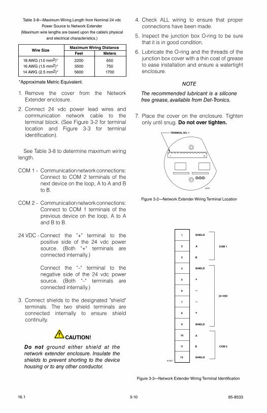
95-85333-1016.1
1. remove the cover from the Network extender enclosure.
2. Connect 24 vdc power lead wires and communication network cable to the terminal block. (see Figure 3-2 for terminal location and Figure 3-3 for terminal identification).
see table 3-8 to determine maximum wiring length.
COM 1 - Communication network connections: Connect to COM 2 terminals of the next device on the loop, A to A and B to B.
COM 2 - Communication network connections: Connect to COM 1 terminals of the previous device on the loop, A to A and B to B.
24 vDC - Connect the "+" terminal to the positive side of the 24 vdc power source. (Both "+" terminals are connected internally.)
Connect the "–" terminal to the negative side of the 24 vdc power source. (Both "–" terminals are connected internally.)
3. Connect shields to the designated "shield" terminals. the two shield terminals are connected internally to ensure shield continuity.
CAUTION!
Do not ground either shield at the network extender enclosure. Insulate the shields to prevent shorting to the device housing or to any other conductor.
4. Check All wiring to ensure that proper connections have been made.
5. Inspect the junction box O-ring to be sure that it is in good condition.
6. lubricate the O-ring and the threads of the junction box cover with a thin coat of grease to ease installation and ensure a watertight enclosure.
noTe
The recommended lubricant is a silicone free grease, available from Det-Tronics.
7. Place the cover on the enclosure. tighten only until snug. Do not over tighten.
TERMINAL NO. 1
1 12
A2021
Figure 3-2—Network Extender Wiring Terminal Location
Table 3-8—Maximum Wiring Length from Nominal 24 vdc
Power Source to Network Extender
(Maximum wire lengths are based upon the cable’s physical
and electrical characteristics.)
*Approximate Metric Equivalent.
Wire Size
Maximum Wiring Distance Feet Meters
18 AWG (1.0 mm2)* 2200 650 16 AWG (1.5 mm2)* 3500 750 14 AWG (2.5 mm2)* 5600 1700
1
2
3
4
5
6
7
8
9
10
A1947
11
12
SHIELD
SHIELD
SHIELD
SHIELD
A
B
A
B
–
+
–
+
COM 2
24 VDC
COM 1
Figure 3-3—Network Extender Wiring Terminal Identification
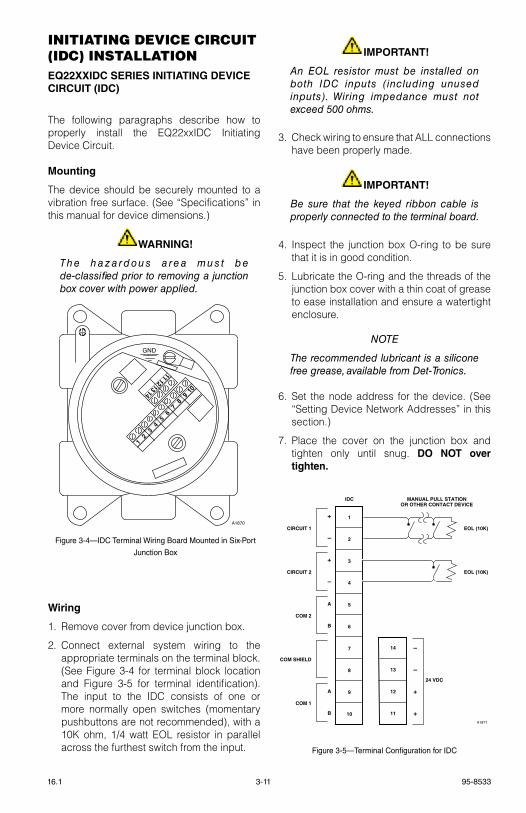
3-11 95-853316.1
InItIAtIng DeVIce cIrcUIt (IDc) InStAllAtIonEQ22XXIDC SERIES INITIATING DEVICE CIRCUIT (IDC)
the following paragraphs describe how to properly install the eQ22xxIDC Initiating Device Circuit.
Mounting
the device should be securely mounted to a vibration free surface. (see “specifications” in this manual for device dimensions.)
WARNING!
Th e h a z a rd o u s a re a m u s t b e de-classified prior to removing a junction box cover with power applied.
Wiring
1. remove cover from device junction box.
2. Connect external system wiring to the appropriate terminals on the terminal block. (see Figure 3-4 for terminal block location and Figure 3-5 for terminal identification). the input to the IDC consists of one or more normally open switches (momentary pushbuttons are not recommended), with a 10k ohm, 1/4 watt eOl resistor in parallel across the furthest switch from the input.
IMPORTANT!
An eoL resistor must be installed on both IDC inputs (including unused inputs). Wiring impedance must not exceed 500 ohms.
3. Check wiring to ensure that All connections have been properly made.
IMPORTANT!
Be sure that the keyed ribbon cable is properly connected to the terminal board.
4. Inspect the junction box O-ring to be sure that it is in good condition.
5. lubricate the O-ring and the threads of the junction box cover with a thin coat of grease to ease installation and ensure a watertight enclosure.
noTe
The recommended lubricant is a silicone free grease, available from Det-Tronics.
6. set the node address for the device. (see “setting Device Network Addresses” in this section.)
7. Place the cover on the junction box and tighten only until snug. DO NOT over tighten.
GND
910
78
56
34
12
1314
1112
A1870
Figure 3-4—IDC Terminal Wiring Board Mounted in Six-Port
Junction Box
1
2
3
4
5
6
7
8
9
10
IDC MANUAL PULL STATIONOR OTHER CONTACT DEVICE
14
13
12
11
–
–
+
+
24 VDC
+
–
+
–
A
B
A
B
CIRCUIT 1
CIRCUIT 2
COM 2
COM SHIELD
COM 1
EOL (10K)
EOL (10K)
A1871
Figure 3-5—Terminal Configuration for IDC
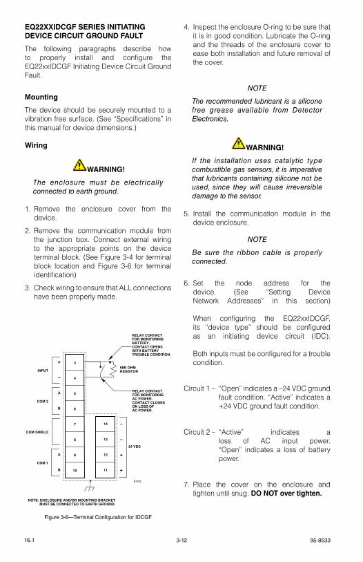
95-85333-1216.1
EQ22XXIDCGF SERIES INITIATING DEVICE CIRCUIT GROUND FAULT
the following paragraphs describe how to properly install and configure the eQ22xxIDCgF Initiating Device Circuit ground Fault.
Mounting
the device should be securely mounted to a vibration free surface. (see “specifications” in this manual for device dimensions.)
Wiring
WARNING!
The enclosure must be electrically connected to earth ground.
1. remove the enclosure cover from the device.
2. remove the communication module from the junction box. Connect external wiring to the appropriate points on the device terminal block. (see Figure 3-4 for terminal block location and Figure 3-6 for terminal identification)
3. Check wiring to ensure that All connections have been properly made.
4. Inspect the enclosure O-ring to be sure that it is in good condition. lubricate the O-ring and the threads of the enclosure cover to ease both installation and future removal of the cover.
noTe
The recommended lubricant is a silicone free grease available from Detector electronics.
WARNING!
If the installation uses catalytic type combustible gas sensors, it is imperative that lubricants containing silicone not be used, since they will cause irreversible damage to the sensor.
5. Install the communication module in the device enclosure.
noTe
Be sure the ribbon cable is properly connected.
6. set the node address for the device. (see “setting Device Network Addresses” in this section) When configuring the eQ22xxIDCgF, its “device type” should be configured as an initiating device circuit (IDC). Both inputs must be configured for a trouble condition.
Circuit 1 – “Open” indicates a –24 vDC ground fault condition. “Active” indicates a +24 vDC ground fault condition.
Circuit 2 – “Active” indicates a loss of AC input power. “Open” indicates a loss of battery power.
7. Place the cover on the enclosure and tighten until snug. DO NOT over tighten.
Figure 3-6—Terminal Configuration for IDCGF
3
4
5
6
7
8
9
10
14
13
12
11
–
–
+
+
24 VDC
+
–
A
B
A
B
INPUT
COM 2
COM SHIELD
COM 1
68K OHMRESISTOR
RELAY CONTACT FOR MONITORING BATTERY.CONTACT OPENS WITH BATTERY TROUBLE CONDITION.
RELAY CONTACT FOR MONITORING AC POWER.CONTACT CLOSES ON LOSS OF AC POWER.
B1922
NOTE: ENCLOSURE AND/OR MOUNTING BRACKET MUST BE CONNECTED TO EARTH GROUND.
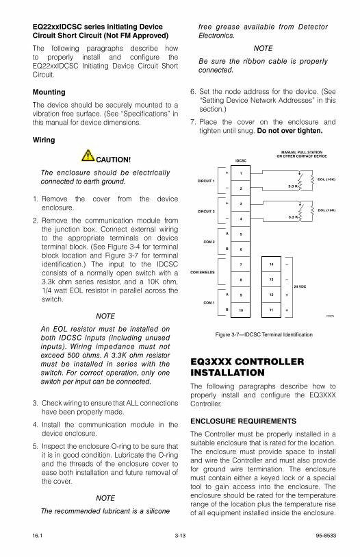
3-13 95-853316.1
EQ22xxIDCSC series initiating Device Circuit Short Circuit (Not FM Approved)
the following paragraphs describe how to properly install and configure the eQ22xxIDCsC Initiating Device Circuit short Circuit.
Mounting
the device should be securely mounted to a vibration free surface. (see “specifications” in this manual for device dimensions.
Wiring
CAUTION!
The enclosure should be electrically connected to earth ground.
1. remove the cover from the device enclosure.
2. remove the communication module from the junction box. Connect external wiring to the appropriate terminals on device terminal block. (see Figure 3-4 for terminal block location and Figure 3-7 for terminal identification.) the input to the IDCsC consists of a normally open switch with a 3.3k ohm series resistor, and a 10k ohm, 1/4 watt eOl resistor in parallel across the switch.
noTe
An eoL resistor must be installed on both IDCSC inputs (including unused inputs). Wiring impedance must not exceed 500 ohms. A 3.3K ohm resistor must be installed in series with the switch. For correct operation, only one switch per input can be connected.
3. Check wiring to ensure that All connections have been properly made.
4. Install the communication module in the device enclosure.
5. Inspect the enclosure O-ring to be sure that it is in good condition. lubricate the O-ring and the threads of the enclosure cover to ease both installation and future removal of the cover.
noTe
The recommended lubricant is a silicone
free grease available from Detector electronics.
noTe
Be sure the ribbon cable is properly connected.
6. set the node address for the device. (see “setting Device Network Addresses” in this section.)
7. Place the cover on the enclosure and tighten until snug. Do not over tighten.
1
2
3
4
5
6
7
8
9
10
IDCSC
MANUAL PULL STATIONOR OTHER CONTACT DEVICE
14
13
12
11
–
–
+
+
24 VDC
+
–
+
–
A
B
A
B
CIRCUIT 1
CIRCUIT 2
COM 2
COM SHIELDS
COM 1
C2076
EOL (10K)
3.3 K
EOL (10K)
3.3 K
Figure 3-7—IDCSC Terminal Identification
eQ3XXX controller InStAllAtIonthe following paragraphs describe how to properly install and configure the eQ3XXX Controller.
ENCLOSURE REQUIREMENTS
the Controller must be properly installed in a suitable enclosure that is rated for the location. the enclosure must provide space to install and wire the Controller and must also provide for ground wire termination. the enclosure must contain either a keyed lock or a special tool to gain access into the enclosure. the enclosure should be rated for the temperature range of the location plus the temperature rise of all equipment installed inside the enclosure.
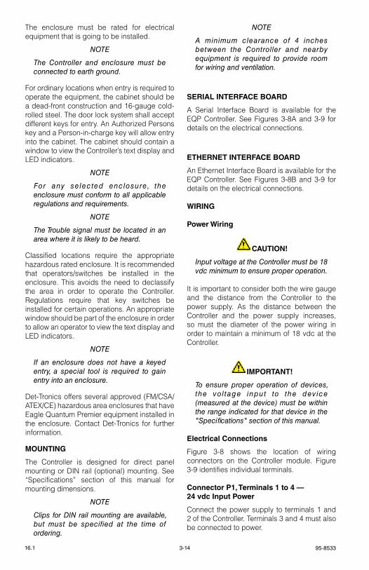
95-85333-1416.1
the enclosure must be rated for electrical equipment that is going to be installed.
noTe
The Controller and enclosure must be connected to earth ground.
For ordinary locations when entry is required to operate the equipment, the cabinet should be a dead-front construction and 16-gauge cold-rolled steel. the door lock system shall accept different keys for entry. An Authorized Persons key and a Person-in-charge key will allow entry into the cabinet. the cabinet should contain a window to view the Controller’s text display and leD indicators.
noTe
For any selected enclosure, the enclosure must conform to all applicable regulations and requirements.
noTe
The Trouble signal must be located in an area where it is likely to be heard.
Classified locations require the appropriate hazardous rated enclosure. It is recommended that operators/switches be installed in the enclosure. this avoids the need to declassify the area in order to operate the Controller. regulations require that key switches be installed for certain operations. An appropriate window should be part of the enclosure in order to allow an operator to view the text display and leD indicators.
noTe
If an enclosure does not have a keyed entry, a special tool is required to gain entry into an enclosure.
Det-tronics offers several approved (FM/CsA/AteX/Ce) hazardous area enclosures that have eagle Quantum Premier equipment installed in the enclosure. Contact Det-tronics for further information.
MOUNTING
the Controller is designed for direct panel mounting or DIN rail (optional) mounting. see “specifications” section of this manual for mounting dimensions.
noTe
Clips for DIn rail mounting are available, but must be specified at the time of ordering.
noTe
A minimum clearance of 4 inches between the Controller and nearby equipment is required to provide room for wiring and ventilation.
SERIAL INTERFACE BOARD
A serial Interface Board is available for the eQP Controller. see Figures 3-8A and 3-9 for details on the electrical connections.
ETHERNET INTERFACE BOARD
An ethernet Interface Board is available for the eQP Controller. see Figures 3-8B and 3-9 for details on the electrical connections.
WIRING
Power Wiring
CAUTION!
Input voltage at the Controller must be 18 vdc minimum to ensure proper operation.
It is important to consider both the wire gauge and the distance from the Controller to the power supply. As the distance between the Controller and the power supply increases, so must the diameter of the power wiring in order to maintain a minimum of 18 vdc at the Controller.
IMPORTANT!
To ensure proper operation of devices, the vol tage input to the device (measured at the device) must be within the range indicated for that device in the "Specifications" section of this manual.
Electrical Connections
Figure 3-8 shows the location of wiring connectors on the Controller module. Figure 3-9 identifies individual terminals.
Connector P1, Terminals 1 to 4 — 24 vdc Input Power
Connect the power supply to terminals 1 and 2 of the Controller. terminals 3 and 4 must also be connected to power.
3-15 95-853316.1
When controller and power supplies are installed in separate Nrtl cabinets, two power cables from two distribution circuits are required, so that if one is lost, the controller will continue to operate and signal a trouble condition. the power circuit must be protected against physical damage.
shields on power cables must be connected to chassis ground (earth).
Connector P2, Terminals 5 to12 — Unsupervised Digital Input Channels 1 to 4
Connector P3, Terminals 13 to 20 — Unsupervised Digital Input Channels 5 to 8
see Figure 3-10 for example. Only channel 1 is shown in Figure 3-10. the information is typical for channels 2-8.
Connector P4, Terminals 21 to 32 — Unsupervised Relay Output Channels 1 to 4
Connector P5, Terminals 33 to 44 — Unsupervised Relay Output Channels 5 to 8
see Figure 3-11 for example. Only channel 1 is shown in Figure 3-11. the information is typical for channels 2-8.
noTe
Channel software configurat ions include all panel indicator functions to automatically mimic the controller front panel indicators.
Connector P6, Terminals 45, 46 & 47 — Trouble Relay
the trouble relay is not configurable. In the normal condition, the relay coil is energized,
closing the N.O. contact (terminals 45-46) and opening the N.C. contact (terminals 45-47). the relay coil is de-energized in the trouble condition.
Connector P7, Terminals 48 to 53 — LON Signaling Line Circuit Terminals
the lON loop is wired so that the controller’s lON COM 1 is connected to the field device’s COM 2 connection. the field device’s COM 1 is wired to the next device’s COM 2 connection. this continues through the last field device on the loop. the last field device’s COM 1 is then wired back to the Controller’s COM 2 connection. lON A and B polarities must be maintained throughout the loop (i.e., always wire A to A and B to B between the devices).
Port Pinout (6-position connection terminal block)48 — COM 1 shield connection49 — "B" side of signaling circuit for COM 150 — "A" side of signaling circuit for COM 151 — COM 2 shield connection52 — "B" side of signaling circuit for COM 253 — "A" side of signaling circuit for COM 2
noTe
Refer to Figures 3-12A and 3-12B for location of termination jumpers.
Jumper P24 – RS-485 Termination Jumper
1-2 Unterminated 2-3 terminated 121 ohms (factory setting) transceiver input impedance: 68 kohm
Jumper P25 – LON COM 1 Termination
1-2 COM 1 terminated (factory setting)2-3 COM 1 Unterminated (redundancy)
Figure 3-10—Unsupervised Input Wiring
COMMON, –
INPUT, +
P2
6
5
A2117
Figure 3-11—Unsupervised Relay Output
P4
N. C. 23
N. O. 22
COMMON 21
A2118
+
–
95-85333-1616.1
P9:
T
ER
MIN
AL
S 5
7 TO
59
R
S-2
32 S
3 C
ON
FIG
UR
AT
ION
PO
RT
P11
: T
ER
MIN
AL
S 6
3 TO
65
– P
OR
T 3
R
S-2
32 M
OD
BU
S R
TU
MA
ST
ER
/SL
AV
E
OR
S3
CO
NF
IGU
RA
TIO
N
P12
: T
ER
MIN
AL
S 6
6 TO
68
– P
OR
T 4
R
S-2
32 M
OD
BU
S R
TU
MA
ST
ER
/SL
AV
E
P10
: T
ER
MIN
AL
S 6
0 TO
62
- P
OR
T 2
R
S-4
85 M
OD
BU
S R
TU
MA
ST
ER
/SL
AV
E
P8:
T
ER
MIN
AL
S 5
4 TO
56
- P
OR
T 1
R
S-4
85 M
OD
BU
S R
TU
MA
ST
ER
/SL
AV
E
P7:
T
ER
MIN
AL
S 4
8 TO
53
LO
N C
ON
NE
CT
ION
S
P6:
T
ER
MIN
AL
S 4
5 TO
47
FA
ULT
RE
LA
Y (
NC
CO
NTA
CT
)
P5:
T
ER
MIN
AL
S 3
3 TO
44
R
EL
AY
S 5
TO
8
P4:
T
ER
MIN
AL
S 2
1 TO
32
R
EL
AY
S 1
TO
4
P3:
T
ER
MIN
AL
S 1
3 TO
20
D
IGIT
AL
INP
UT
S 5
TO
8
P2:
T
ER
MIN
AL
S 5
TO
12
D
IGIT
AL
INP
UT
S 1
TO
4
P1:
T
ER
MIN
AL
S 1
TO
4
24 V
DC
INP
UT
PO
WE
R
G21
05
EA
GL
E Q
UA
NT
UM
PR
EM
IER
Safe
ty S
yste
m C
on
tro
ller
Fire
Ala
rmIn
hibi
tP
ower
Sup
rH
igh
Gas
Trou
ble
Cnt
rl F
lt
Lon
Faul
tLo
w G
asA
ckS
ilenc
e
Out
Inhi
bit
Eag
le Q
uant
um P
rem
ier
Tim
e &
Dat
e
Can
cel
En
ter
Nex
tP
revi
ou
sR
eset
Ack
no
wle
dg
eS
ilen
ce
14
6062
6365
6668
512
1320
2132
3344
4547
485354565759
CO
NT
RO
LN
ET
BN
C C
ON
NE
CTO
R A OR
ETH
ER
NE
T D
LR R
J45
CO
NN
EC
TOR
PO
RT
1
CO
NT
RO
LN
ET
BN
C C
ON
NE
CTO
R B OR
ETH
ER
NE
T D
LR R
J45
CO
NN
EC
TOR
PO
RT
2
P13
: H
IGH
SP
EE
D S
ER
IAL
LIN
K (
HS
SL
)R
S-2
32 (
RE
DU
ND
AN
CY
ON
LY)
DET
-TRONICS
®
SE
RIA
L IN
TE
RFA
CE
BO
AR
D
Figu
re 3
-8A
—Lo
catio
n of
Wiri
ng T
erm
inal
s on
EQ
P C
ontro
ller
with
Ser
ial I
nter
face
Boa
rd
Jumper P26 – LON COM 2 Termination
1-2 COM 2 terminated (factory setting)2-3 COM 2 Unterminated (redundancy)
Connector P8, Terminals 54, 55 & 56 , Port 1— RS-485 Modbus RTU Master/Slave
Configuration data downloaded into the controller configures the serial interface transmission baud rate, parity check for the serial port, and Modbus device address.
software selectable baud rates are 2400, 4800, 9600,19200, 38400, 57600, and 115200. software selectable parity is None, Odd, and even. the controller uses 8 data bits with 1 stop bit.Port Pinout (3-position terminal block)54 — gND55 — B56 — A
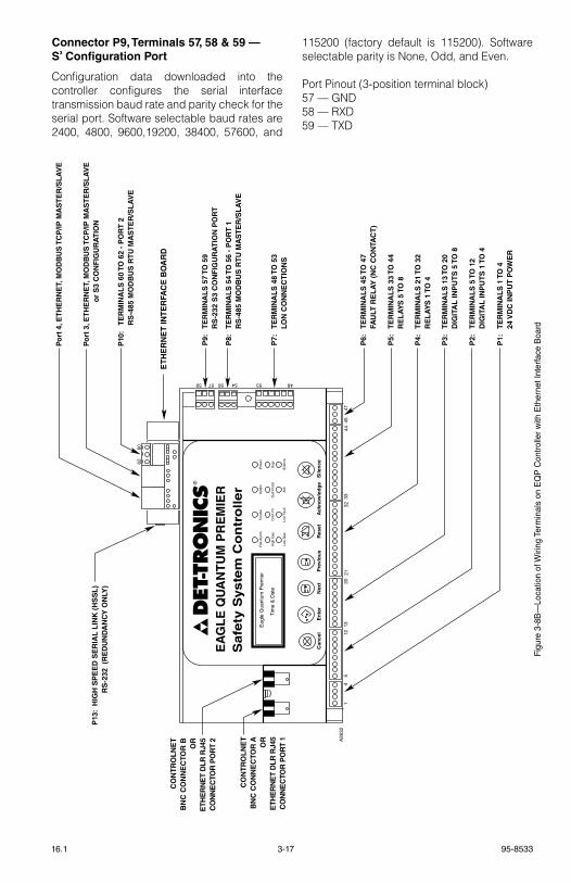
3-17 95-853316.1
Connector P9, Terminals 57, 58 & 59 — S³ Configuration Port
Configuration data downloaded into the controller configures the serial interface transmission baud rate and parity check for the serial port. software selectable baud rates are 2400, 4800, 9600,19200, 38400, 57600, and
115200 (factory default is 115200). software selectable parity is None, Odd, and even.
Port Pinout (3-position terminal block)57 — gND58 — rXD59 — tXD
Figu
re 3
-8B
—Lo
catio
n of
Wiri
ng T
erm
inal
s on
EQ
P C
ontro
ller
with
Eth
erne
t Int
erfa
ce B
oard
P9:
T
ER
MIN
AL
S 5
7 TO
59
R
S-2
32 S
3 C
ON
FIG
UR
AT
ION
PO
RT
Po
rt 3
, ET
HE
RN
ET,
MO
DB
US
TC
P/IP
MA
ST
ER
/SL
AV
E
o
r S
3 C
ON
FIG
UR
AT
ION
Po
rt 4
, ET
HE
RN
ET,
MO
DB
US
TC
P/IP
MA
ST
ER
/SL
AV
E
P10
: T
ER
MIN
AL
S 6
0 TO
62
- P
OR
T 2
R
S-4
85 M
OD
BU
S R
TU
MA
ST
ER
/SL
AV
E
P8:
T
ER
MIN
AL
S 5
4 TO
56
- P
OR
T 1
R
S-4
85 M
OD
BU
S R
TU
MA
ST
ER
/SL
AV
E
P7:
T
ER
MIN
AL
S 4
8 TO
53
LO
N C
ON
NE
CT
ION
S
P6:
T
ER
MIN
AL
S 4
5 TO
47
FA
ULT
RE
LA
Y (
NC
CO
NTA
CT
)
P5:
T
ER
MIN
AL
S 3
3 TO
44
R
EL
AY
S 5
TO
8
P4:
T
ER
MIN
AL
S 2
1 TO
32
R
EL
AY
S 1
TO
4
P3:
T
ER
MIN
AL
S 1
3 TO
20
D
IGIT
AL
INP
UT
S 5
TO
8
P2:
T
ER
MIN
AL
S 5
TO
12
D
IGIT
AL
INP
UT
S 1
TO
4
P1:
T
ER
MIN
AL
S 1
TO
4
24 V
DC
INP
UT
PO
WE
R
A26
32
EA
GL
E Q
UA
NT
UM
PR
EM
IER
Safe
ty S
yste
m C
on
tro
ller
Fire
Ala
rmIn
hibi
tP
ower
Sup
rH
igh
Gas
Trou
ble
Cnt
rl F
lt
Lon
Faul
tLo
w G
asA
ckS
ilenc
e
Out
Inhi
bit
Eag
le Q
uant
um P
rem
ier
Tim
e &
Dat
e
Can
cel
En
ter
Nex
tP
revi
ou
sR
eset
Ack
no
wle
dg
eS
ilen
ce
14
6062
512
1320
2132
3344
4547
485354565759
CO
NT
RO
LN
ET
BN
C C
ON
NE
CTO
R A OR
ETH
ER
NE
T D
LR R
J45
CO
NN
EC
TOR
PO
RT
1
CO
NT
RO
LN
ET
BN
C C
ON
NE
CTO
R B OR
ETH
ER
NE
T D
LR R
J45
CO
NN
EC
TOR
PO
RT
2
P13
: H
IGH
SP
EE
D S
ER
IAL
LIN
K (
HS
SL
)R
S-2
32 (
RE
DU
ND
AN
CY
ON
LY)
DET
-TRONICS
®
ET
HE
RN
ET
INT
ER
FAC
E B
OA
RD
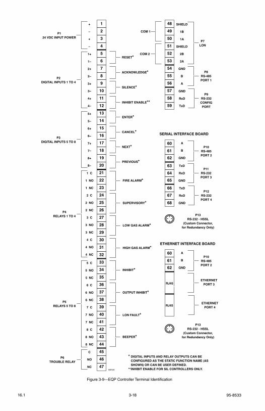
95-85333-1816.1
1
2
3
4
5
6
7
8
9
10
11
12
13
14
15
16
17
18
19
20
21
22
23
24
25
26
27
28
29
303132
33
343536
37
383940
41
424344
45
4647
1 C
1 NO
1 NC
2 C
2 NO
2 NC
3 C
3 NO
3 NC
4 C
4 NO
4 NC
P4RELAYS 1 TO 4
5+
5–
6+
6–
7+
7–
8+
8–
P3DIGITAL INPUTS 5 TO 8
1+
1–
2+
2–
3+
3–
4+
4–
P2DIGITAL INPUTS 1 TO 4
+
–
+
–
P124 VDC INPUT POWER
5 C
5 NO
5 NC
6 C
6 NO
6 NC
7 C
7 NO
7 NC
8 C
8 NO
8 NC
P5RELAYS 5 TO 8
C
NO
NC
P6TROUBLE RELAY
FIRE ALARM*
PREVIOUS*
NEXT*
CANCEL*
ENTER*
INHIBIT ENABLE**
RESET*
ACKNOWLEDGE*
SILENCE*
SUPERVISORY*
LOW GAS ALARM*
HIGH GAS ALARM*
INHIBIT*
OUTPUT INHIBIT*
LON FAULT*
BEEPER*
48
49
50
51
52
53
54
55
56
57
58
59
SHIELD
1B
1A
SHIELD
2B
2A
P7LON
GND
B
A
P8RS-485PORT 1
GND
RxD
TxD
P9RS-232CONFIGPORT
H2104
COM 1
COM 2
* DIGITAL INPUTS AND RELAY OUTPUTS CAN BE CONFIGURED AS THE STATIC FUNCTION NAME (AS SHOWN) OR CAN BE USER DEFINED.** INHIBIT ENABLE FOR SIL CONTROLLERS ONLY.
SERIAL INTERFACE BOARD
606162
636465
6667
68
P10RS-485PORT 2
TxD
RxD
GND
A
B
GND
P11RS-232PORT 3
TxD
RxD
GND
P12RS-232PORT 4
P13RS-232 - HSSL
(Custom Connector,for Redundancy Only)
ETHERNET INTERFACE BOARD
606162
P10RS-485PORT 2
RJ45
RJ45
A
B
GND
ETHERNETPORT 3
ETHERNETPORT 4
P13RS-232 - HSSL
(Custom Connector,for Redundancy Only)
Figure 3-9—EQP Controller Terminal Identification

3-19 95-853316.1
Connector P10, Terminals 60, 61 & 62, Port 2– RS-485 Modbus RTU Master/Slave
Configuration data downloaded into the controller configures the serial interface transmission baud rate, parity check for the serial port, and Modbus device address. software selectable baud rates are 9600,19200, 38400, 57600, 115200 and 230400. software selectable parity is None, Odd, and even. the controller uses 8 data bits with 1 stop bit.
Port Pinout (3-position terminal block)60 — A61 — B62 — gND
Serial Interface Board Jumpers
Jumper P25 – RS-485 Termination Jumper, Port 2
1-2 terminated 121 ohms (factory setting)2-3 Unterminated transceiver input impedance: 68 kohm
Jumper P3 – RS-485 Ground Fault Monitor, Port 2
1-2 enabled2-3 Disabled (factory setting)
Ethernet Interface Board Jumpers Jumper P6 – RS-485 Termination Jumper, Port 2
1-2 terminated 121 ohms (factory setting)2-3 Unterminated transceiver input impedance: 68 kohm
Jumper P5 – RS-485 Ground Fault Monitor, Port 2
1-2 enabled2-3 Disabled (factory setting)Use Port 2 to pass safety critical information between controllers. ensure that ground Fault Monitoring is enabled. User logic can pass all alarm, trouble, and supervisory information between the controllers. Watchdog timers must be implemented in user logic to verify the integrity of the slC. Consult the local authority having jurisdiction for annunciation requirements.
CONTROLLER TO CONTROLLER COMMUNICATION
Controller to Controller Communication (SLC485) with Signaling Line Circuit Classification Class B or X, per NFPA 72
to connect up to twelve controllers together and be able to transfer safety information between the controllers, the communication link must be classified as a signaling line circuit per NFPA 72. With the serial Interface Board, Port 2 (plug 10) is a rs-485 serial connection that is ground fault monitored.
to meet the signaling line circuit (Class B or Class X) requirements, the following must be configured for correct operation:• All controllers must have the same type
Interface Board (ethernet or serial) installed.
CAUTION
When using the ethernet Interface Board, controllers communicating over P10, Port 2 - RS-485 are required to be located within the same room or be wired in conduit within 20 feet (6 meters) for signalling line transient protection.
• the termination jumper P28 must be set to terminate (position 1-2) on all controllers.
• the ground Fault Monitor jumper P29 must be set to enabled (position 1-2) on all controllers.
• For Class X, Connect terminals A (# 56) and B (# 55) between the controllers. Connect terminal A (# 60) and B (# 61) between controllers using a different cable route. Connect gND (# 54) to gND (# 62) on each controller.
• For Class B, connect terminals A (terminal number 60) and B (terminal number 61) between the controllers. the gND (terminal number 62) must not be connected.
see Figure 3-13A and 3-13B for wiring details.
Note 1: 56.7 kbps minimum and 115.2 kbps maximum baud rate required for proper communication.
Note 2: Consult the factory for configuration set-up.
Note 3: Maximum slC485 length over copper not to exceed 1000 meters.
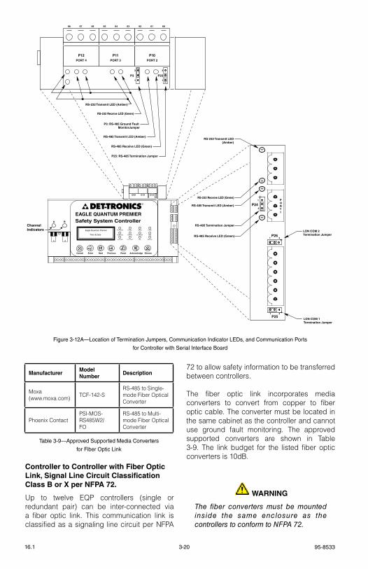
95-85333-2016.1
Controller to Controller with Fiber Optic Link, Signal Line Circuit Classification Class B or X per NFPA 72.
Up to twelve eQP controllers (single or redundant pair) can be inter-connected via a fiber optic link. this communication link is classified as a signaling line circuit per NFPA
72 to allow safety information to be transferred between controllers.
the fiber optic link incorporates media converters to convert from copper to fiber optic cable. the converter must be located in the same cabinet as the controller and cannot use ground fault monitoring. the approved supported converters are shown in table 3-9. the link budget for the listed fiber optic converters is 10dB.
WARNING
The fiber converters must be mounted inside the same enclosure as the controllers to conform to nFPA 72.
1P25
3
1
60616467 6263656668
P263
P241
3
RS-232 Receive LED (Green)
RS-232 Receive LED (Green)
RS-485 Transmit LED (Amber)
RS-485 Transmit LED (Amber)
RS-485 Termination Jumper
P25: RS-485 Termination Jumper
P3: RS-485 Ground Fault MonitorJumper
A B
ChannelIndicators
RS-485 Receive LED (Green)
RS-485 Receive LED (Green)
RS-232 Transmit LED(Amber)
RS-232 Transmit LED (Amber)
LON COM 2Termination Jumper
LON COM 1Termination Jumper
P25
1
3
P3
1
3
P12PORT 4
P11PORT 3
P10PORT 2
PORT1EAGLE QUANTUM PREMIER
Safety System Controller
Fire Alarm Inhibit Power
SuprHigh Gas
Trouble
Cntrl Flt
Lon FaultLow Gas Ack Silence
Out Inhibit
Eagle Quantum Premier
Time & Date
Cancel Enter Next Previous Reset Acknowledge Silence
DET-TRONICS®
Figure 3-12A—Location of Termination Jumpers, Communication Indicator LEDs, and Communication Ports
for Controller with Serial Interface Board
Table 3-9—Approved Supported Media Converters
for Fiber Optic Link
ManufacturerModel Number
Description
Moxa (www.moxa.com) tCF-142-s
rs-485 to single-mode Fiber Optical Converter
Phoenix ContactPsI-MOs-rs485W2/FO
rs-485 to Multi-mode Fiber Optical Converter
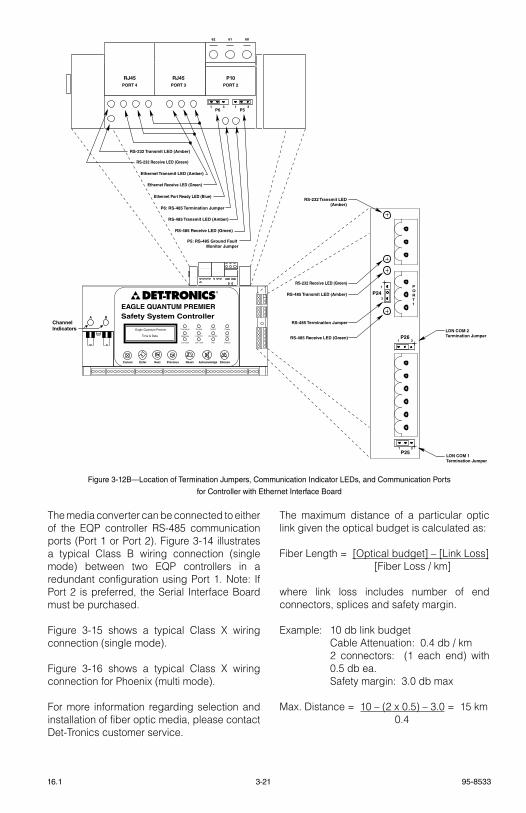
3-21 95-853316.1
the media converter can be connected to either of the eQP controller rs-485 communication ports (Port 1 or Port 2). Figure 3-14 illustrates a typical Class B wiring connection (single mode) between two eQP controllers in a redundant configuration using Port 1. Note: If Port 2 is preferred, the serial Interface Board must be purchased.
Figure 3-15 shows a typical Class X wiring connection (single mode).
Figure 3-16 shows a typical Class X wiring connection for Phoenix (multi mode).
For more information regarding selection and installation of fiber optic media, please contact Det-tronics customer service.
Figure 3-12B—Location of Termination Jumpers, Communication Indicator LEDs, and Communication Ports
for Controller with Ethernet Interface Board
1P25
3
1
606162
P263
P241
3
RS-232 Receive LED (Green)
Ethernet Receive LED (Green)
RS-232 Receive LED (Green)
Ethernet Port Ready LED (Blue)
RS-485 Transmit LED (Amber)
RS-485 Transmit LED (Amber)
RS-485 Termination Jumper
P6: RS-485 Termination Jumper
P5: RS-485 Ground Fault Monitor Jumper
A B
ChannelIndicators
RS-485 Receive LED (Green)
RS-485 Receive LED (Green)
RS-232 Transmit LED(Amber)
Ethernet Transmit LED (Amber)
RS-232 Transmit LED (Amber)
LON COM 2Termination Jumper
LON COM 1Termination Jumper
P61 3
P51 3
RJ45PORT 4
RJ45PORT 3
P10PORT 2
PORT1EAGLE QUANTUM PREMIER
Safety System Controller
Fire Alarm Inhibit Power
SuprHigh Gas
Trouble
Cntrl Flt
Lon FaultLow Gas Ack Silence
Out Inhibit
Eagle Quantum Premier
Time & Date
Cancel Enter Next Previous Reset Acknowledge Silence
DET-TRONICS®
the maximum distance of a particular optic link given the optical budget is calculated as:
Fiber length = [Optical budget] – [link loss] [Fiber loss / km]
where link loss includes number of end connectors, splices and safety margin.
example: 10 db link budget Cable Attenuation: 0.4 db / km 2 connectors: (1 each end) with 0.5 db ea. safety margin: 3.0 db max
Max. Distance = 10 – (2 x 0.5) – 3.0 = 15 km 0.4
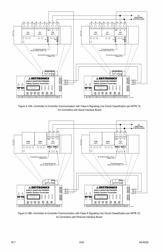
95-85333-2216.1
6062 61 616365 6467 64676668
P25: RS-485 Termination Jumper,Position 1 & 2
P3: RS-485 Ground Fault Monitor Jumper, Position 1 & 2
A B
P251
3
P31
3
P12PORT 4
P11PORT 3
P10PORT 2
606263656668
P25: RS-485 Termination Jumper,Position 1 & 2
P3: RS-485 Ground Fault Monitor Jumper, Position 1 & 2
A B
P25
1
3
P3
1
3
P12PORT 4
P11PORT 3
P10PORT 2
GND AB GND AB
E2276
TOADDITIONAL
CONTROLLER(S)
545556
545556EAGLE QUANTUM PREMIER
Safety System Controller
Fire Alarm Inhibit Power
SuprHigh Gas
Trouble
Cntrl Flt
Lon FaultLow Gas Ack Silence
Out Inhibit
Eagle Quantum Premier
Time & Date
Cancel Enter Next Previous Reset Acknowledge Silence
DET-TRONICS®
EAGLE QUANTUM PREMIERSafety System Controller
Fire Alarm Inhibit Power
SuprHigh Gas
Trouble
Cntrl Flt
Lon FaultLow Gas Ack Silence
Out Inhibit
Eagle Quantum Premier
Time & Date
Cancel Enter Next Previous Reset Acknowledge Silence
DET-TRONICS®
6062 61 61
A B
RJ45PORT 4
RJ45PORT 3
P10PORT 2
6062
A B
P5: RS-485 Ground Fault Monitor Jumper, Position 1 & 2
P6: RS-485 Termination Jumper,Position 1 & 2
P5: RS-485 Ground Fault Monitor Jumper, Position 1 & 2
P6: RS-485 Termination Jumper,Position 1 & 2
RJ45PORT 4
RJ45PORT 3
P10PORT 2
GND AB GND AB
A2633
TOADDITIONAL
CONTROLLER(S)
545556
545556EAGLE QUANTUM PREMIER
Safety System Controller
Fire Alarm Inhibit Power
SuprHigh Gas
Trouble
Cntrl Flt
Lon FaultLow Gas Ack Silence
Out Inhibit
Eagle Quantum Premier
Time & Date
Cancel Enter Next Previous Reset Acknowledge Silence
DET-TRONICS®
EAGLE QUANTUM PREMIERSafety System Controller
Fire Alarm Inhibit Power
SuprHigh Gas
Trouble
Cntrl Flt
Lon FaultLow Gas Ack Silence
Out Inhibit
Eagle Quantum Premier
Time & Date
Cancel Enter Next Previous Reset Acknowledge Silence
DET-TRONICS®
P61 3
P51 3
P61 3
P51 3
Figure 3-13A—Controller to Controller Communication with Class A Signaling Line Circuit Classification per NFPA 72,
for Controllers with Serial Interface Board
Figure 3-13B—Controller to Controller Communication with Class A Signaling Line Circuit Classification per NFPA 72,
for Controllers with Ethernet Interface Board

3-23 95-853316.1
Connector P11, Terminals 63, 64 & 65, Port 3– (Serial Interface Board only) RS-232 Modbus RTU Master/Slave or S³ Configuration Port (Non-Isolated)
Configuration data downloaded into the controller configures the serial interface transmission baud rate, parity check and MODBUs device address for the serial port. software selectable baud rates are 9600,19200, 38400, 57600, 115200, and 230400. software selectable parity is None, Odd, and even. the controller uses 8 data bits with 1 stop bit.
Port Pinout (3-position terminal block)63 — tXD64 — rXD65 — gND
RJ45, Port 3 (Ethernet Interface Board only) Ethernet Modbus TCP Client/Server or S³ Configuration Port (Non-Isolated)
Configuration data downloaded into the controller configures the ethernet interface IP address, subnet mask, gateway, and local port number. this port may be used as a Modbus tCP Client or a Modbus tCP server. this port may also be used as an alternate s³
configuration port. eQP controllers come from the factory with the following default values for Port 3:
Port 3 IP Address 192.168.127.251
Port 3 Subnet Mask 255.255.255.000
noTe
Maximum Modbus update time per port is 250 mSec.
Connector P12, Terminals 66, 67 & 68, Port 4– (Serial Interface Board only) RS-232 Modbus RTU Master/Slave (Non-Isolated)
Configuration data downloaded into the controller configures the serial interface transmission baud rate, parity check and MODBUs device address for the serial port. software selectable baud rates are 9600,19200, 38400, 57600, 115200, and 230400. software selectable parity is None, Odd, and even. the controller uses 8 data bits with 1 stop bit.
Port Pinout (3-position terminal block)66 — tXD67 — rXD68 — gND
RJ45, Port 4 (Ethernet Interface Board only)
ethernet Modbus tCP Client/serverConfiguration data downloaded into the controller configures the ethernet interface IP address, subnet mask, gateway, and local port number. this port may be used as a Modbus tCP Client or a Modbus tCP server. eQP controllers come from the factory with the following default values for Port 4:
Port 4 IP Address 192.168.127.252
Port 4 Subnet Mask 255.255.255.000
noTe
Maximum Modbus update time per port is 250 mSec.
Connector P13 — RS-232 High Speed Serial Port
this port is dedicated to inter-controller connection required for redundancy, and is not available for any other use. this port is automatically configured.
CONFIGURATION
Software Defined Addresses
Det-tronics safety system software (s³) is programmed with the addresses that are assigned to the controller when the configuration file is downloaded into the controller. Addresses define and configure the Controller’s lON address, Modbus slave address, ControlNet option board address, and ethernet Dlr option board address. each device on the lON must be assigned a unique tag number. this tag number must include zone designation, which will be shown on the Controller's display when the device is in alarm.
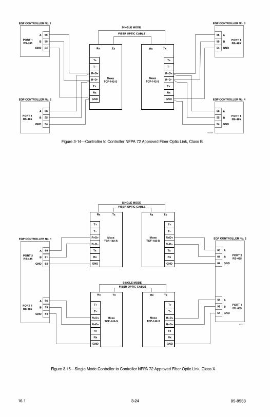
95-85333-2416.1
Figure 3-14—Controller to Controller NFPA 72 Approved Fiber Optic Link, Class B
PORT 1RS-485
A
B
GND
56
55
54
PORT 1RS-485
EQP CONTROLLER No. 1
56
55
54
A
B
GND
EQP CONTROLLER No. 2
PORT 1RS-485
56
55
54
A
B
GND
EQP CONTROLLER No. 3
PORT 1RS-485
56
55
54
A
B
GND
EQP CONTROLLER No. 4
T+
T–
R+D+
R–D–
Tx
Rx
GND
TxRx
MoxaTCF-142-S
T+
T–
R+D+
R–D–
Tx
Rx
GND
Rx Tx
MoxaTCF-142-S
FIBER OPTIC CABLE
B2328
SINGLE MODE
PORT 1RS-485
A
B
GND
60
61
62
PORT 2RS-485
EQP CONTROLLER No. 1
56
55
54
A
B
GND
PORT 2RS-485
60
61
62
A
B
GND
EQP CONTROLLER No. 2
PORT 1RS-485
56
55
54
A
B
GND
T+
T–
R+D+
R–D–
Tx
Rx
GND
TxRx
MoxaTCF-142-S
T+
T–
R+D+
R–D–
Tx
Rx
GND
Rx Tx
MoxaTCF-142-S
T+
T–
R+D+
R–D–
Tx
Rx
GND
TxRx
MoxaTCF-142-S
T+
T–
R+D+
R–D–
Tx
Rx
GND
Rx Tx
MoxaTCF-142-S
B2371
FIBER OPTIC CABLESINGLE MODE
FIBER OPTIC CABLESINGLE MODE
Figure 3-15—Single Mode Controller to Controller NFPA 72 Approved Fiber Optic Link, Class X
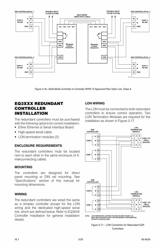
3-25 95-853316.1
eQ3XXX reDUnDAnt controller InStAllAtIonthe redundant controllers must be purchased with the following options for correct installation:• either ethernet or serial Interface Board• High-speed serial cable• lON termination modules (2).
ENCLOSURE REQUIREMENTS
the redundant controllers must be located next to each other in the same enclosure (4 ft. interconnecting cable).
MOUNTING
the controllers are designed for direct panel mounting or DIN rail mounting. see “specifications” section of this manual for mounting dimensions.
WIRING
the redundant controllers are wired the same as a simplex controller except for the lON wiring and the dedicated high-speed serial link, which are defined below. refer to eQ3XXX Controller Installation for general installation details.
LON WIRING
the lON must be connected to both redundant controllers to ensure correct operation. two lON termination Modules are required for the installation as shown in Figure 3-17.
C2274
A
B
S
COM 2
A
B
S
COM 1
EQPCONTROLLER
53
52
51
50
49
48
A
B
S
COM 2
A
B
S
COM 1
EQPCONTROLLER
53
52
51
50
49
48
NOTE: LON TERMINATION JUMPERS P25 AND P26 (SEE FIGURE 3-12) MUST BE IN POSITION 2 AND 3 FOR REDUNDANT CONFIGURATION (ON BOTH CONTROLLERS).
LONTERMINATION
MODULE
A3
2
1
6
5
4
B
S
COM 2 TOFIELD
DEVICES
LONTERMINATION
MODULE
A3
2
1
6
5
4
B
S
COM 1 TOFIELD
DEVICES
Figure 3-17— LON Connection for Redundant EQP
Controllers
PORT 2RS-485
A
B
GND
60
61
62
PORT 2RS-485
EQP CONTROLLER No. 1
60
61
62
A
B
GND
EQP CONTROLLER No. 2
PORT 2RS-485
60
61
62
A
B
GND
EQP CONTROLLER No. 3
PORT 2RS-485
60
61
62
A
B
GND
EQP CONTROLLER No. 4
D(P)
D(N)
GND
BRDBTDARDATD ARDATDBRDBTD
PhoenixPSI-MOS-
RS485W2/FO
PhoenixPSI-MOS-
RS485W2/FO
D(P)
D(N)
GND
FIBER OPTIC CABLE
B2372
MULTI MODE
TROUBLE INPUT TO EQP SYSTEM
TROUBLE INPUT TO EQP SYSTEM
Figure 3-16—Multi-Mode Controller to Controller NFPA 72 Approved Fiber Optic Link, Class X
95-85333-2616.1
HIGH SPEED SERIAL LINK (HSSL)
the redundant controllers are connected together by a dedicated high-speed serial link. this link is a pre-fabricated cable that has a custom connector for ease of use. redundant controllers are automatically addressed with the Hssl cable. One end of the cable is labeled Primary. the primary controller takes address 1, while the secondary controller is address 2. the significance this has for the user is that the primary is the default master when both controllers are powered-up at the same time.
CONFIGURATION
S³ Configuration
the s³ configuration software is used to configure the redundant controllers. A check box on the controller configuration screen must be enabled and downloaded to the controllers.
IMPORTANT
I f the control lers have not been configured for redundancy via the S³ configuration software, redundancy will not function.
Controller Addresses
the lON addresses are pre-determined and cannot be adjusted. Address 1 and 2 have been reserved for a redundant controller configuration.
RS485/RS232 (Port 1 through Port 4)
rs485/rs232 ports 1 through 4 on each controller share the serial settings including baud rate and address. Controllers in standby mode don’t respond to or issue Modbus rtU messages. this allows for transparent switching on a multi-drop network. If rs-232 is used, a relay switching mechanism can be used.
ControlNet
the ControlNet interface on each controller will have a different address. this allows both controllers to reside on the same ControlNet network at the same time. the primary controller uses the configured address while the standby assumes an address 1 higher than the primary controller. Application logic in the attached PlC must be used to determine which
controller has the correct output information. Information coming from the PlC should be written to both Premier Controllers.
Ethernet DLR
the ethernet Dlr interface on each controller will have a different address. this allows both to reside on the same network at the same time. the primary controller uses the configured address while the standby assumes an address 1 higher than the primary controller. Application logic in the attached PlC must be used to determine which controller has the correct output information. Information coming from the PlC should be written to both Premier Controllers.
Ethernet
the ethernet interface ports on each controller will all have unique IP addresses. this allows both controllers to reside on the same ethernet network at the same time. the primary and secondary controller IP addresses for ports 3 and 4 are part of the configuration data. During the configuration download, the primary controller assigns the primary IP address to itself and passes the secondary IP address on to the secondary controller. Controllers in standby mode do not respond to Modbus tCP/IP messages. ethernet applications need to redirect to the alternate IP address when controller switchovers occur.
eQ21XXpS SerIeS poWer SUpply AnD poWer SUpply MonItor InStAllAtIon
WARNING!
ALWAYS follow all safety notes and instructions when installing power supply or batteries!
WARNING!
Make sure a.c. power is oFF at main a.c. breaker before beginning power supply installation!
IMPORTANT!
Power supplies require unrestricted air flow for proper cooling.

3-27 95-853316.1
MOUNTING
Mount the power supply monitor in a Nationally recognized test laboratory (Nrtl) labeled enclosure. refer to the “specifications” section for mounting dimensions.
WIRING
CAUTION!
The power supply should be properly connected to an earth ground! A ground wire MUST be connected to the power supply units’s case ground!
noTe
The Power Supply Monitor uses two of the four DIP switches to select an appropriate fault level for the installation. See Figure 3-18. The unit will fault when the batteries source a current level higher than the threshold for 20 seconds. The fault will clear when the current drops to half the level for 20 seconds. The current level selection is based on the minimum current draw of the attached equipment. The selected value must be less than the actual minimum current draw for the system.
1. verify that the input source is the same voltage and frequency as that marked on the nameplate of the power supply.
2. verify that transformer taps are set for the correct a.c. input. (Input tap setting is located inside the power supply enclosure.)
3. verify that the supply power wire size and fusing are adequate for the current indicated on the power supply nameplate.
noTe
Consult the power supply manufacturer’s instruction manual provided with the support documentation received with the eagle Quantum System.
noTe
Required overload Current is usually equal to 15% of the nominal rating.
4. Connect external wiring to the appropriate points on Power supply. refer to Figure 3-18 for terminal block locations and Figures 3-19 and 3-20 for terminal identification. Connect the 24 vdc power wires and the lON network cable to the appropriate points on J1. (redundant “+”, “–” and shield terminals are connected internally.) Do not ground any shield at the monitor / power distribution cabinet. Insulate the shields to prevent shorting to the device housing or to any other conductor.
5. Connect a two wire cable between the AC input of the power supply and terminals 1 and 4 on J3, the AC input terminal block on the power supply monitor. see Figure 3-20.
6. Connect the “B” terminal on the power supply monitor to the negative (–) side of the backup battery. Connect a correctly sized circuit breaker in the battery circuit as shown in Figure 3-21. the circuit breaker must be rated between 130% and 250% of the total load.
7. Connect the “C” terminal on the power supply monitor to the negative (–) side of the power supply.
8. Wire the power distribution circuit breakers to the output of the power supply. Circuit breaker ratings must be between 130% and 250% of the full load rating.
9. set the device network address for the power supply monitor.
noTe
For additional information, refer to the power supply manufacturer’s instruction manual provided with the support documentation received with the eagle Quantum Premier system.
STARTUP
turn on the power supply and allow the voltage to stabilize at 27 volts before closing the circuit to the battery.

95-85333-2816.1
MEASURING BATTERY VOLTAGE AND CHARGING CURRENT
Measure the battery voltage at terminals 3 and 4 of terminal block J2. see Figure 3-18 and 3-22.
to measure the battery charging current, connect a digital voltmeter to terminals 1 and 2 of terminal block J2. the voltmeter will read 1 millivolt (0.001 volt) for each 2 amperes of current.
Current in Amperes = Meter reading in millivolts x 2
example: A reading of 50 millivolts indicates a charging current of 100 amperes.
+
J1: POWER AND LON WIRING LON ADDRESS SWITCHES J3: AC INPUT
TERMINAL NO. 1
YELLOW LED
RED LED
GREEN LED
TERMINAL NO. 1
TERMINAL "B"
TERMINAL "C"
J2: BATTERY TEST POINTS
TERMINAL NO. 1
SWITCH NO. 1
1
1
1234
1
C1949
ALARM LEVEL 1 2 3 4
200 mA O O – –
400 mA X O – –
800 mA O X – –
2 AMP X X – –X = CLOSEDO = OPEN
ALARM CURRENT LEVEL SWITCH SETTINGS
TERMINAL J2-1 TO TERMINAL B
TERMINAL J2-2 TO TERMINAL C
POWER SUPPLY MONITORPC BOARD ASSEMBLY
J2
NOTE: J2 TERMINALS 3 AND 4 ARE CONNECTED TO J1 TERMINALS 7 AND 8 INTERNALLY ON THE PC BOARD. J1 TERMINALS 7 AND 8 ARE ALSO CONNECTED TO THE BATTERY CIRCUIT BREAKER VIA POWER DIST CKT.
+ –
0.0005 OHM SHUNT
Figure 3-18—Power Supply Monitor Terminal and Switch Location
1
2
3
4
5
6
7
8
9
10
A1947
11
12
SHIELD
SHIELD
SHIELD
SHIELD
A
B
A
B
–
+
–
+
COM 2
24 VDC
COM 1
Figure 3-19—J1: Power and LON Wiring Terminal
A1950
1
2
3
4
AC INPUT 120 / 240 VAC
AC INPUT 120 / 240 VAC
NOT USED
NOT USED
Figure 3-20—J3: AC Input Terminal
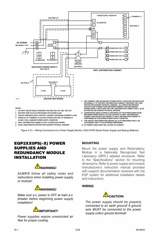
3-29 95-853316.1
eQp2XX0pS(–X) poWer SUpplIeS AnD reDUnDAncy MoDUle InStAllAtIon
WARNING!
ALWAYS follow all safety notes and instructions when installing power supply or module!
WARNING!
Make sure a.c. power is oFF at main a.c. breaker before beginning power supply installation!
IMPORTANT!
Power supplies require unrestricted air flow for proper cooling.
MOUNTING
Mount the power supply and redundancy Module in a Nationally recognized test laboratory (Nrtl) labeled enclosure. refer to the “specifications” section for mounting dimensions. refer to power supply and module manufacturer's instruction manual provided with support documentation received with the eQP system for additional installation details and instructions.
WIRING
CAUTION!
The power supply should be properly connected to an earth ground! A ground wire MUST be connected to the power supply units’s ground terminal!
1
4
C
B
AC BREAKER DC BREAKER
H
N
G
–
+
24 VDCOUTPUT
POWER SUPPLY MONITOR 121110987654321
EQ21XXPS POWER SUPPLY(See Note 9)
– +
12 VDC
– +
12 VDC
NRTL DISTRIBUTION CABINET
BATTERYCIRCUIT
BREAKER
–
+ –
–
–
–
+
+
+
+
POWER DIST CKT #1
POWER DIST CKT #2
POWER DIST CKT #3
POWER DIST CKT #4
NOTES
1. AC INPUT SELECTABLE (THROUGH THE OIS) FOR 120 / 208 / 240 VAC.
2. BATTERY SIZE CALCULATED BASED ON SYSTEM LOAD.
3. CIRCUIT BREAKER SHALL PROTECT AGAINST EXCESSIVE CURRENT LOAD.
4. REMOVAL OF TERMINAL PLUG WITH POWER APPLIED TO TERMINALS
B AND C WILL DAMAGE POWER SUPPLY MONITOR.
5. NRTL DISTRIBUTION CABINET IS KEY LOCKED ENCLOSURE.
6. DASH LINES DENOTE PROTECTION AGAINST PHYSICAL DAMAGE.
E1951
AC MONITOR
BACKUP BATTERIES
AC POWERSee Notes 1 & 3
See Note 3
See Note 2
See Note 4
See Note 10
See Note 6
TERMINAL J1
7. ANY PRIMARY AND SECONDARY POWER SUPPLY UNITS MAY BE INSTALLED EXTERNALLY TO THE NRTL DISTRIBUTION CABINET, PROVIDED THEY ARE PROTECTED AGAINST PHYSICAL DAMAGE. ALL DEDICATED BRANCH CIRCUITS AND CONNECTIONS BETWEEN PRIMARY AND SECONDARY POWER SUPPLY UNITS AND THE NTRL DISTRIBUTION CABINET SHALL ALSO BE PROTECTED AGAINST PHYSICAL DAMAGE.
8. SUPERVISION (SINGLE OPENS & GROUNDS) OF THE INTERCONNECTIONS BETWEEN POWER SUPPLY (24 VDC OUTPUT) TO NRTL DISTRIBUTION CABINET AND BACKUP BATTERIES TO NRTL DISTRIBUTION CABINET IS PERFORMED BY EQ2100PSM POWER SUPPLY MONITOR.
9. THE CIRCUIT DISCONNECTING MEANS (AC & DC BREAKERS) SHALL BE ACCESSIBLE ONLY TO AUTHORIZED PERSONNEL.
10. AC WIRING CABLE MUST BE ≤20 FEET IN CONDUIT.
Figure 3-21— Wiring Connections for a Power Supply Monitor, EQ21XXPS Series Power Supply and Backup Batteries
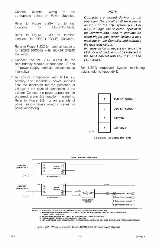
95-85333-3016.1
1. Connect external wiring to the appropriate points on Power supplies. refer to Figure 3-23A for terminal locations for eQP21X0Ps(-X). refer to Figure 3-23B for terminal locations for eQP2410Ps(-P) Converter. refer to Figure 3-23C for terminal locations for eQP2120Ps(-X) with eQP2410Ps(-P) Converter.
2. Connect the 24 vDC output to the redundancy Module. (redundant “+” and “–” power supply terminals are connected internally.)
3. to ensure compliance with NFPA 72, primary and secondary power supplies shall be monitored for the presence of voltage at the point of connection to the system. Connect the power supply unit for preferred preventive function monitoring. refer to Figure 3-24 for an example of power supply relays wired in series for power monitoring.
noTe
Contacts are closed during normal operation. The circuit shall be wired to an input on the eQP system (eDIo or IDC). In Logic, the selected input must be inverted and used to activate an alarm trigger gate, which initiates a fault message on the Controller and activates the fault relay output.no supervision is necessary, since the eDIo or IDC module must be installed in the same cabinet with eQP21X0PS and eQP2410PS.
For UsCg Approved system monitoring details, refer to Appendix D.
A1952
1
2
3
4
CURRENT SENSE +
BATTERY +
CURRENT SENSE –
BATTERY –
Figure 3-22—J2: Battery Test Points
NRTL DISTRIBUTION CABINET
–
+ –
–
–
–
+
+
+
+
POWER DIST CKT #1
POWER DIST CKT #2
POWER DIST CKT #3
POWER DIST CKT #4
NOTES: 1. AC INPUT IS AUTO-SELECTABLE FOR 120–220 VAC, 60/50 Hz (CUSTOMER SUPPLIED). 2. PRIMARY SOURCE OF INPUT SUPPLY IS CONNECTED TO ONE POWER SUPPLY AND SECONDARY SOURCE IS CONNECTED TO THE OTHER. 3. A MAXIMUM OF 8 REDUNDANT PAIRS CAN BE CONNECTED TO INPUT AC POWER. 4. THE SECONDARY SOURCE IS CONTINUOUSLY POWERED. 5. EQP CONTROLLER MUST BE INSTALLED IN THE SAME ENCLOSURE AS AC-DC POWER SUPPLIES AND REDUNDANCY MODULE.
D2445
L
N
G
––
++
24 VDCOUTPUT
POWER SUPPLY
AC POWERSee Notes 1 & 2
L
N
G
––
++
24 VDCOUTPUT
POWER SUPPLY
AC POWERSee Notes 1 & 2
IN OUT
REDUNDANCYMODULE
1
2
CB
CB
Figure 3-23A—Wiring Connections for an EQP21X0PS(-X) Power Supply (Typical)
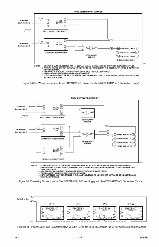
3-31 95-853316.1
Figure 3-23B—Wiring Connections for an EQP2110PS(-P) Power Supply with EQP2410PS(-P) Converter (Typical)
NRTL DISTRIBUTION CABINET
–
+ –
–
–
–
+
+
+
+
POWER DIST CKT #1
POWER DIST CKT #2
POWER DIST CKT #3
POWER DIST CKT #4
NOTES: 1. AC INPUT IS AUTO-SELECTABLE FOR 120–220 VAC, 60/50 Hz. BOTH AC AND DC INPUTS ARE CUSTOMER SUPPLIED. 2. PRIMARY SOURCE OF INPUT SUPPLY IS CONNECTED TO AC POWER SUPPLY AND SECONDARY SOURCE IS CONNECTED TO DC CONVERTER. 3. A MAXIMUM OF 8 REDUNDANT PAIRS CAN BE CONNECTED TO INPUT AC/DC POWER. 4. THE SECONDARY SOURCE IS CONTINUOUSLY POWERED. 5. EQP CONTROLLER MUST BE INSTALLED IN THE SAME ENCLOSURE AS AC-DC POWER SUPPLY, DC-DC CONVERTER, AND REDUNDANCY MODULE.
E2543
+
–
––
++
24 VDCOUTPUT
EQP2410PS(–P) CONVERTER
DC POWERSee Notes 1 & 2
L
N
––
++
24 VDCOUTPUT
EQP2110PS(–P) POWER SUPPLY
AC POWERSee Notes 1 & 2
IN OUT
REDUNDANCYMODULE
1
2
CB
CB
G
NRTL DISTRIBUTION CABINET
–
+
+
–
–
–
–
+
+
+
+
POWER DIST CKT #1
POWER DIST CKT #2
POWER DIST CKT #3
POWER DIST CKT #4
NOTES: 1. AC INPUT IS AUTO-SELECTABLE FOR 120–220 VAC, 60/50 Hz. BOTH AC AND DC INPUTS ARE CUSTOMER SUPPLIED. 2. PRIMARY SOURCE OF INPUT SUPPLY IS CONNECTED TO AC POWER SUPPLY AND SECONDARY SOURCE IS CONNECTED TO DC CONVERTER. 3. A MAXIMUM OF 4 REDUNDANT PAIRS CAN BE CONNECTED TO INPUT AC/DC POWER. 4. THE SECONDARY SOURCE IS CONTINUOUSLY POWERED. 5. EQP CONTROLLER MUST BE INSTALLED IN THE SAME ENCLOSURE AS AC-DC POWER SUPPLY, DC-DC CONVERTER, AND REDUNDANCY MODULE.
A2566
+
–
–
–
+
+
24 VDCOUTPUT
EQP2410PS(–P) CONVERTER
DC POWER
See Notes 1 & 2
L
N
–
–
+
+
24 VDCOUTPUT
EQP2120PS(–X) POWER SUPPLY
AC POWER
See Notes 1 & 2
IN OUT
REDUNDANCYMODULE
1
IN OUT
REDUNDANCYMODULE
1
2
CB
CB
G
+
–
–
–
+
+
24 VDCOUTPUT
EQP2410PS(–P) CONVERTER
Figure 3-23C—Wiring Connections for One EQP2120PS(-X) Power Supply with Two EQP2410PS(-P) Converters (Typical)
To EDIO or IDC
L
N
–
–
+
+
DCOK13 14
PS nPHOENIX
QUINT-PSL
N
–
–
+
+
DCOK13 14
PS 1
PHOENIXQUINT-PS
L
N
–
–
+
+
DCOK13 14
PS
PHOENIXQUINT-PS
L
N
–
–
+
+
DCOK13 14
PS
PHOENIXQUINT-PS
D2438
Figure 3-24—Power Supply and Converter Relays Wired in Series for Trouble Monitoring (up to 16 Power Supplies/Converters)
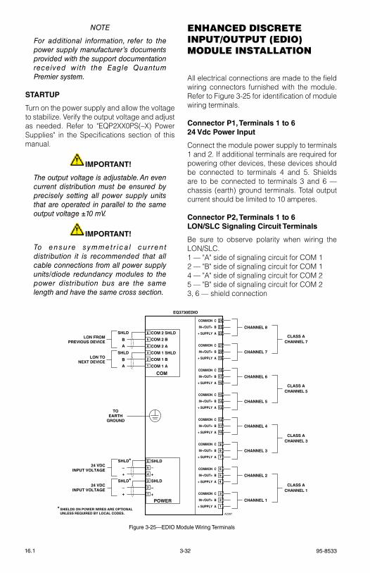
95-85333-3216.1
noTe
For additional information, refer to the power supply manufacturer’s documents provided with the support documentation received with the eagle Quantum Premier system.
STARTUP
turn on the power supply and allow the voltage to stabilize. verify the output voltage and adjust as needed. refer to "eQP2XX0Ps(–X) Power supplies" in the specifications section of this manual.
IMPORTANT!
The output voltage is adjustable. An even current distribution must be ensured by precisely setting all power supply units that are operated in parallel to the same output voltage ±10 mV.
IMPORTANT!
To ensu re symmet r i ca l cu r ren t distribution it is recommended that all cable connections from all power supply units/diode redundancy modules to the power distribution bus are the same length and have the same cross section.
enHAnceD DIScrete InpUt/oUtpUt (eDIo) MoDUle InStAllAtIon
All electrical connections are made to the field wiring connectors furnished with the module. refer to Figure 3-25 for identification of module wiring terminals.
Connector P1, Terminals 1 to 624 Vdc Power Input
Connect the module power supply to terminals 1 and 2. If additional terminals are required for powering other devices, these devices should be connected to terminals 4 and 5. shields are to be connected to terminals 3 and 6 — chassis (earth) ground terminals. total output current should be limited to 10 amperes.
Connector P2, Terminals 1 to 6LON/SLC Signaling Circuit Terminals
Be sure to observe polarity when wiring the lON/slC.1 — "A" side of signaling circuit for COM 12 — "B" side of signaling circuit for COM 14 — "A" side of signaling circuit for COM 25 — "B" side of signaling circuit for COM 23, 6 — shield connection
CHANNEL 8
CHANNEL 7
CHANNEL 6
CLASS ACHANNEL 7
CLASS ACHANNEL 5
CLASS ACHANNEL 3
CLASS ACHANNEL 1
CHANNEL 5
CHANNEL 4
CHANNEL 3
CHANNEL 2
CHANNEL 1
COM
6
5
4
3
2
1
COM 2 SHLD
COM 2 B
COM 2 A
COM 1 SHLD
COM 1 B
COM 1 A
SHLD
B
A
SHLD
B
A
LON FROMPREVIOUS DEVICE
LON TONEXT DEVICE
POWER
6
5
4
3
2
1
SHLD
–
+
SHLD
–
+
SHLD*–
+
SHLD*–
+
24 VDCINPUT VOLTAGE
24 VDCINPUT VOLTAGE
EQ3730EDIO
TOEARTH
GROUND
A2287
+ SUPPLY A
IN–/OUT+ B
COMMON C
+ SUPPLY A
IN–/OUT+ B
COMMON C
+ SUPPLY A
IN–/OUT+ B
COMMON C
+ SUPPLY A
IN–/OUT+ B
COMMON C
+ SUPPLY A
IN–/OUT+ B
COMMON C
+ SUPPLY A
IN–/OUT+ B
COMMON C
+ SUPPLY A
IN–/OUT+ B
COMMON C
+ SUPPLY A
IN–/OUT+ B
COMMON C
1
2
3
4
5
6
7
8
9
10
11
12
13
14
15
16
17
18
19
20
21
22
23
24
* SHIELDS ON POWER WIRES ARE OPTIONAL UNLESS REQUIRED BY LOCAL CODES.
Figure 3-25—EDIO Module Wiring Terminals
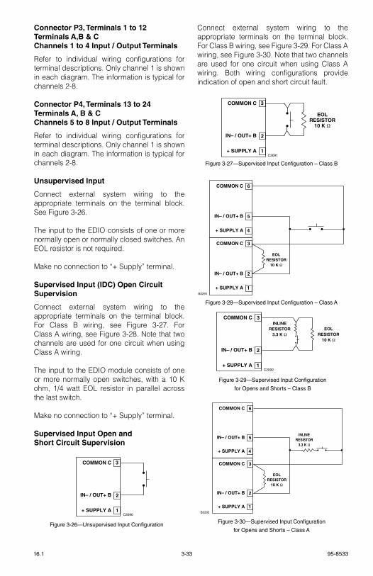
3-33 95-853316.1
Connector P3, Terminals 1 to 12Terminals A,B & CChannels 1 to 4 Input / Output Terminals
refer to individual wiring configurations for terminal descriptions. Only channel 1 is shown in each diagram. the information is typical for channels 2-8.
Connector P4, Terminals 13 to 24 Terminals A, B & C Channels 5 to 8 Input / Output Terminals
refer to individual wiring configurations for terminal descriptions. Only channel 1 is shown in each diagram. the information is typical for channels 2-8.
Unsupervised Input
Connect external system wiring to the appropriate terminals on the terminal block. see Figure 3-26.
the input to the eDIO consists of one or more normally open or normally closed switches. An eOl resistor is not required.
Make no connection to “+ supply” terminal.
Supervised Input (IDC) Open Circuit Supervision
Connect external system wiring to the appropriate terminals on the terminal block. For Class B wiring, see Figure 3-27. For Class A wiring, see Figure 3-28. Note that two channels are used for one circuit when using Class A wiring.
the input to the eDIO module consists of one or more normally open switches, with a 10 k ohm, 1/4 watt eOl resistor in parallel across the last switch.
Make no connection to “+ supply” terminal.
Supervised Input Open and Short Circuit Supervision
Connect external system wiring to the appropriate terminals on the terminal block. For Class B wiring, see Figure 3-29. For Class A wiring, see Figure 3-30. Note that two channels are used for one circuit when using Class A wiring. Both wiring configurations provide indication of open and short circuit fault.
+ SUPPLY A
IN– / OUT+ B
COMMON C
1
2
3
EOLRESISTOR
10 K Ω
C2091
Figure 3-27—Supervised Input Configuration – Class B
+ SUPPLY A
IN– / OUT+ B
COMMON C
1
2
3
EOLRESISTOR
10 K Ω
INLINERESISTOR
3.3 K Ω
C2092
Figure 3-29—Supervised Input Configuration
for Opens and Shorts – Class B
+ SUPPLY A
IN– / OUT+ B
COMMON C
1
2
3
+ SUPPLY A
IN– / OUT+ B
COMMON C
4
5
6
B2291
EOLRESISTOR
10 K Ω
Figure 3-28—Supervised Input Configuration – Class A
+ SUPPLY A
IN– / OUT+ B
COMMON C
1
2
3
+ SUPPLY A
IN– / OUT+ B
COMMON C
4
5
6
B2292
INLINERESISTOR
3.3 K Ω
EOLRESISTOR
10 K Ω
Figure 3-30—Supervised Input Configuration
for Opens and Shorts – Class A
+ SUPPLY A
IN– / OUT+ B
COMMON C
1
2
3
C2090
Figure 3-26—Unsupervised Input Configuration
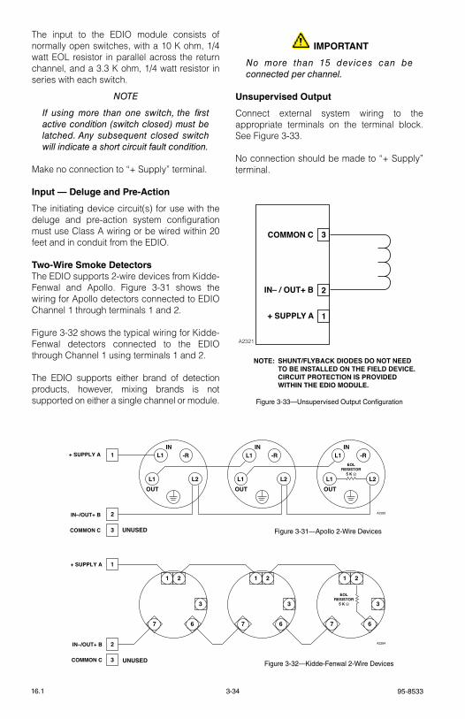
95-85333-3416.1
the input to the eDIO module consists of normally open switches, with a 10 k ohm, 1/4 watt eOl resistor in parallel across the return channel, and a 3.3 k ohm, 1/4 watt resistor in series with each switch.
noTe
If using more than one switch, the first active condition (switch closed) must be latched. Any subsequent closed switch will indicate a short circuit fault condition.
Make no connection to “+ supply” terminal.
Input — Deluge and Pre-Action
the initiating device circuit(s) for use with the deluge and pre-action system configuration must use Class A wiring or be wired within 20 feet and in conduit from the eDIO.
Two-Wire Smoke Detectorsthe eDIO supports 2-wire devices from kidde-Fenwal and Apollo. Figure 3-31 shows the wiring for Apollo detectors connected to eDIO Channel 1 through terminals 1 and 2.
Figure 3-32 shows the typical wiring for kidde-Fenwal detectors connected to the eDIO through Channel 1 using terminals 1 and 2.
the eDIO supports either brand of detection products, however, mixing brands is not supported on either a single channel or module.
IMPORTANT
no more than 15 devices can be connected per channel.
Unsupervised Output
Connect external system wiring to the appropriate terminals on the terminal block. see Figure 3-33.
No connection should be made to “+ supply” terminal.
IN
OUT
UNUSED
OUT OUT
IN IN
A2283
1 -R
L1 L2
L1L1 -R
L1 L2
L1 -R
L1 L2
2
3
+ SUPPLY A
IN–/OUT+ B
COMMON C
EOLRESISTOR
5 K Ω
Figure 3-31—Apollo 2-Wire Devices
A2284
1
2
3 UNUSED
3
67
1 2
3
67
1 2
3
67
1 2
+ SUPPLY A
IN–/OUT+ B
COMMON C
EOLRESISTOR
5 K Ω
Figure 3-32—Kidde-Fenwal 2-Wire Devices
+ SUPPLY A
IN– / OUT+ B
COMMON C
1
2
3
NOTE: SHUNT/FLYBACK DIODES DO NOT NEED TO BE INSTALLED ON THE FIELD DEVICE. CIRCUIT PROTECTION IS PROVIDED WITHIN THE EDIO MODULE.
A2321
Figure 3-33—Unsupervised Output Configuration
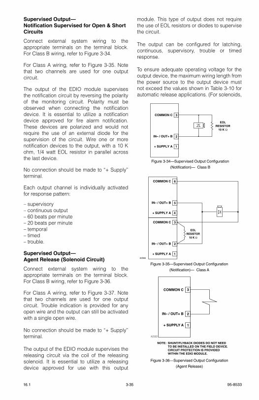
3-35 95-853316.1
Supervised Output— Notification Supervised for Open & Short Circuits
Connect external system wiring to the appropriate terminals on the terminal block. For Class B wiring, refer to Figure 3-34.
For Class A wiring, refer to Figure 3-35. Note that two channels are used for one output circuit.
the output of the eDIO module supervises the notification circuit by reversing the polarity of the monitoring circuit. Polarity must be observed when connecting the notification device. It is essential to utilize a notification device approved for fire alarm notification. these devices are polarized and would not require the use of an external diode for the supervision of the circuit. Wire one or more notification devices to the output, with a 10 k ohm, 1/4 watt eOl resistor in parallel across the last device.
No connection should be made to “+ supply” terminal.
each output channel is individually activated for response pattern:
– supervisory – continuous output – 60 beats per minute – 20 beats per minute – temporal – timed – trouble.
Supervised Output— Agent Release (Solenoid Circuit)
Connect external system wiring to the appropriate terminals on the terminal block. For Class B wiring, refer to Figure 3-36.
For Class A wiring, refer to Figure 3-37. Note that two channels are used for one output circuit. trouble indication is provided for any open wire and the output can still be activated with a single open wire.
No connection should be made to “+ supply” terminal.
the output of the eDIO module supervises the releasing circuit via the coil of the releasing solenoid. It is essential to utilize a releasing device approved for use with this output
module. this type of output does not require the use of eOl resistors or diodes to supervise the circuit.
the output can be configured for latching, continuous, supervisory, trouble or timed response.
to ensure adequate operating voltage for the output device, the maximum wiring length from the power source to the output device must not exceed the values shown in table 3-10 for automatic release applications. (For solenoids,
+ SUPPLY A
IN– / OUT+ B
COMMON C
1
2
3
EOLRESISTOR
10 K Ω
Figure 3-34—Supervised Output Configuration
(Notification)— Class B
+ SUPPLY A
IN– / OUT+ B
COMMON C
1
2
3
NOTE: SHUNT/FLYBACK DIODES DO NOT NEED TO BE INSTALLED ON THE FIELD DEVICE. CIRCUIT PROTECTION IS PROVIDED WITHIN THE EDIO MODULE.
A2322
Figure 3-36—Supervised Output Configuration
(Agent Release)
+ SUPPLY A
IN– / OUT+ B
COMMON C
1
2
3
+ SUPPLY A
IN– / OUT+ B
COMMON C
4
5
6
A2285
EOLRESISTOR
10 K Ω
Figure 3-35—Supervised Output Configuration
(Notification)— Class A
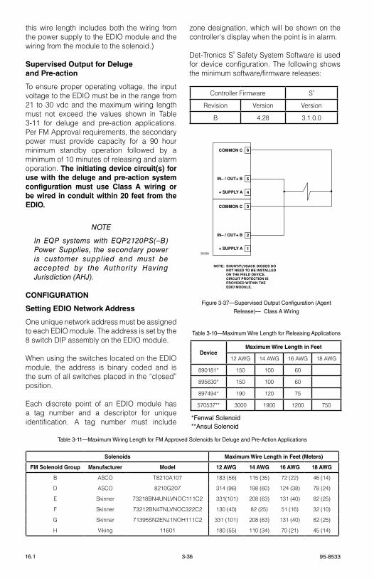
95-85333-3616.1
this wire length includes both the wiring from the power supply to the eDIO module and the wiring from the module to the solenoid.)
Supervised Output for Deluge and Pre-action
to ensure proper operating voltage, the input voltage to the eDIO must be in the range from 21 to 30 vdc and the maximum wiring length must not exceed the values shown in table 3-11 for deluge and pre-action applications. Per FM Approval requirements, the secondary power must provide capacity for a 90 hour minimum standby operation followed by a minimum of 10 minutes of releasing and alarm operation. The initiating device circuit(s) for use with the deluge and pre-action system configuration must use Class A wiring or be wired in conduit within 20 feet from the EDIO.
noTe
In eQP systems with eQP2120PS(–B) Power Supplies, the secondary power is customer supplied and must be accepted by the Authority Having Jurisdiction (AHJ).
CONFIGURATION
Setting EDIO Network Address
One unique network address must be assigned to each eDIO module. the address is set by the 8 switch DIP assembly on the eDIO module.
When using the switches located on the eDIO module, the address is binary coded and is the sum of all switches placed in the “closed” position.
each discrete point of an eDIO module has a tag number and a descriptor for unique identification. A tag number must include
zone designation, which will be shown on the controller's display when the point is in alarm.
Det-tronics s³ safety system software is used for device configuration. the following shows the minimum software/firmware releases:
Controller Firmware s³
revision version version
B 4.28 3.1.0.0
+ SUPPLY A
IN– / OUT+ B
COMMON C
1
2
3
+ SUPPLY A
IN– / OUT+ B
COMMON C
4
5
6
NOTE: SHUNT/FLYBACK DIODES DO NOT NEED TO BE INSTALLED ON THE FIELD DEVICE. CIRCUIT PROTECTION IS PROVIDED WITHIN THE EDIO MODULE.
B2286
Figure 3-37—Supervised Output Configuration (Agent
Release)— Class A Wiring
Table 3-10—Maximum Wire Length for Releasing Applications
*Fenwal Solenoid**Ansul Solenoid
DeviceMaximum Wire Length in Feet
12 AWg 14 AWg 16 AWg 18 AWg
890181* 150 100 60
895630* 150 100 60
897494* 190 120 75
570537** 3000 1900 1200 750
Table 3-11—Maximum Wiring Length for FM Approved Solenoids for Deluge and Pre-Action Applications
Solenoids Maximum Wire Length in Feet (Meters)
FM Solenoid Group Manufacturer Model 12 AWG 14 AWG 16 AWG 18 AWG
B AsCO t8210A107 183 (56) 115 (35) 72 (22) 46 (14)
D AsCO 8210g207 314 (96) 198 (60) 124 (38) 78 (24)
e skinner 73218BN4UNlvNOC111C2 331(101) 208 (63) 131 (40) 82 (25)
F skinner 73212BN4tNlvNOC322C2 130 (40) 82 (25) 51 (16) 32 (10)
g skinner 71395sN2eNJ1NOH111C2 331 (101) 208 (63) 131 (40) 82 (25)
H viking 11601 180 (55) 110 (34) 70 (21) 45 (14)
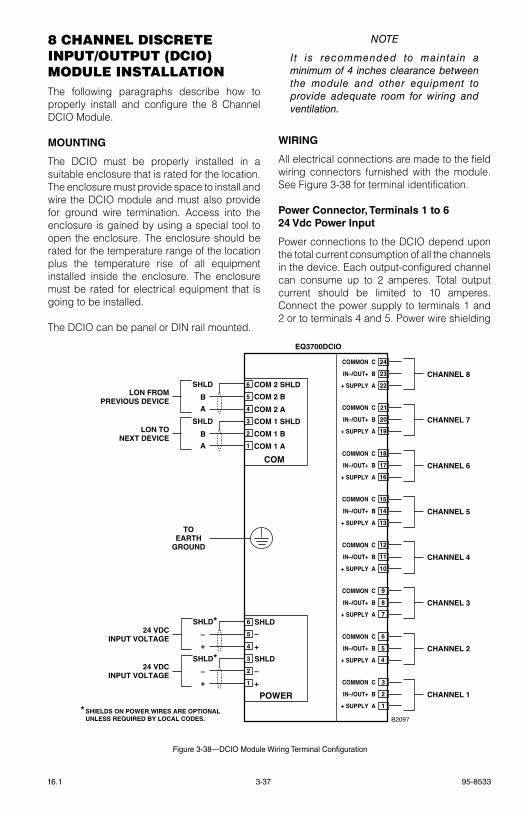
3-37 95-853316.1
8 cHAnnel DIScrete InpUt/oUtpUt (DcIo) MoDUle InStAllAtIonthe following paragraphs describe how to properly install and configure the 8 Channel DCIO Module.
MOUNTING
the DCIO must be properly installed in a suitable enclosure that is rated for the location. the enclosure must provide space to install and wire the DCIO module and must also provide for ground wire termination. Access into the enclosure is gained by using a special tool to open the enclosure. the enclosure should be rated for the temperature range of the location plus the temperature rise of all equipment installed inside the enclosure. the enclosure must be rated for electrical equipment that is going to be installed.
the DCIO can be panel or DIN rail mounted.
noTe
It is recommended to maintain a minimum of 4 inches clearance between the module and other equipment to provide adequate room for wiring and ventilation.
WIRING
All electrical connections are made to the field wiring connectors furnished with the module. see Figure 3-38 for terminal identification.
Power Connector, Terminals 1 to 6 24 Vdc Power Input
Power connections to the DCIO depend upon the total current consumption of all the channels in the device. each output-configured channel can consume up to 2 amperes. total output current should be limited to 10 amperes. Connect the power supply to terminals 1 and 2 or to terminals 4 and 5. Power wire shielding
CHANNEL 8
CHANNEL 7
CHANNEL 6
CHANNEL 5
CHANNEL 4
CHANNEL 3
CHANNEL 2
CHANNEL 1
COM
6
5
4
3
2
1
COM 2 SHLD
COM 2 B
COM 2 A
COM 1 SHLD
COM 1 B
COM 1 A
SHLD
B
A
SHLD
B
A
LON FROMPREVIOUS DEVICE
LON TONEXT DEVICE
POWER
6
5
4
3
2
1
SHLD
–
+
SHLD
–
+
SHLD*–
+
SHLD*–
+
24 VDCINPUT VOLTAGE
24 VDCINPUT VOLTAGE
EQ3700DCIO
TOEARTH
GROUND
B2097
+ SUPPLY A
IN–/OUT+ B
COMMON C
+ SUPPLY A
IN–/OUT+ B
COMMON C
+ SUPPLY A
IN–/OUT+ B
COMMON C
+ SUPPLY A
IN–/OUT+ B
COMMON C
+ SUPPLY A
IN–/OUT+ B
COMMON C
+ SUPPLY A
IN–/OUT+ B
COMMON C
+ SUPPLY A
IN–/OUT+ B
COMMON C
+ SUPPLY A
IN–/OUT+ B
COMMON C
1
2
3
4
5
6
7
8
9
10
11
12
13
14
15
16
17
18
19
20
21
22
23
24
* SHIELDS ON POWER WIRES ARE OPTIONAL UNLESS REQUIRED BY LOCAL CODES.
Figure 3-38—DCIO Module Wiring Terminal Configuration
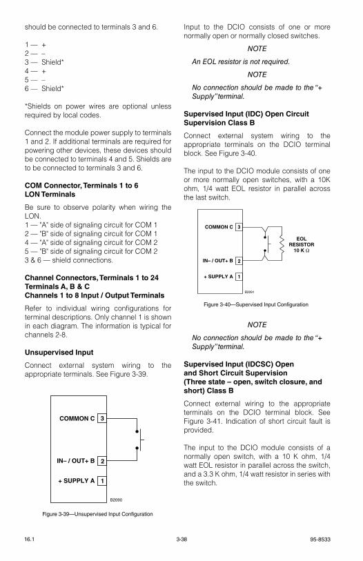
95-85333-3816.1
should be connected to terminals 3 and 6.
1 — +2 — –3 — shield*4 — +5 — –6 — shield*
*shields on power wires are optional unless required by local codes.
Connect the module power supply to terminals 1 and 2. If additional terminals are required for powering other devices, these devices should be connected to terminals 4 and 5. shields are to be connected to terminals 3 and 6.
COM Connector, Terminals 1 to 6 LON Terminals
Be sure to observe polarity when wiring the lON.1 — "A" side of signaling circuit for COM 12 — "B" side of signaling circuit for COM 14 — "A" side of signaling circuit for COM 25 — "B" side of signaling circuit for COM 23 & 6 — shield connections.
Channel Connectors, Terminals 1 to 24 Terminals A, B & C Channels 1 to 8 Input / Output Terminals
refer to individual wiring configurations for terminal descriptions. Only channel 1 is shown in each diagram. the information is typical for channels 2-8.
Unsupervised Input
Connect external system wiring to the appropriate terminals. see Figure 3-39.
Input to the DCIO consists of one or more normally open or normally closed switches.
noTe
An eoL resistor is not required.
noTe
no connection should be made to the “+ Supply” terminal.
Supervised Input (IDC) Open Circuit Supervision Class B
Connect external system wiring to the appropriate terminals on the DCIO terminal block. see Figure 3-40.
the input to the DCIO module consists of one or more normally open switches, with a 10k ohm, 1/4 watt eOl resistor in parallel across the last switch.
noTe
no connection should be made to the “+ Supply” terminal.
Supervised Input (IDCSC) Open and Short Circuit Supervision (Three state – open, switch closure, and short) Class B
Connect external wiring to the appropriate terminals on the DCIO terminal block. see Figure 3-41. Indication of short circuit fault is provided.
the input to the DCIO module consists of a normally open switch, with a 10 k ohm, 1/4 watt eOl resistor in parallel across the switch, and a 3.3 k ohm, 1/4 watt resistor in series with the switch.+ SUPPLY A
IN– / OUT+ B
COMMON C
1
2
3
B2090
Figure 3-39—Unsupervised Input Configuration
+ SUPPLY A
IN– / OUT+ B
COMMON C
1
2
3
EOLRESISTOR
10 K Ω
B2091
Figure 3-40—Supervised Input Configuration
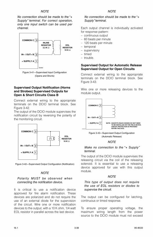
3-39 95-853316.1
noTe
no connection should be made to the “+ Supply” terminal. For correct operation, only one input switch can be used per channel.
Supervised Output Notification (Horns and Strobes) Supervised Outputs for Open & Short Circuits Class B
Connect external wiring to the appropriate terminals on the DCIO terminal block. see Figure 3-42.the output of the DCIO module supervises the notification circuit by reversing the polarity of the monitoring circuit.
noTe
Polarity MUST be observed when connecting the notification device.
It is critical to use a notification device approved for fire alarm notification. these devices are polarized and do not require the use of an external diode for the supervision of the circuit. Wire one or more notification devices to the output, with a 10 k ohm, 1/4 watt eOl resistor in parallel across the last device.
noTe
no connection should be made to the “+ Supply” terminal.
each output channel is individually activated for response pattern:– continuous output– 60 beats per minute– 120 beats per minute– temporal– supervisory– timed– trouble.
Supervised Output for Automatic Release Supervised Output for Open Circuits
Connect external wiring to the appropriate terminals on the DCIO terminal block. see Figure 3-43.
Wire one or more releasing devices to the module output.
noTe
Make no connection to the “+ Supply” terminal.
the output of the DCIO module supervises the releasing circuit via the coil of the releasing solenoid. It is essential to use a releasing device approved for use with this output module.
noTe
This type of output does not require the use of eoL resistors or diodes to supervise the circuit.
the output can be configured for latching, continuous or timed response.
to ensure proper operating voltage, the maximum wiring length from the power source to the DCIO module must not exceed
+ SUPPLY A
IN– / OUT+ B
COMMON C
1
2
3
EOLRESISTOR
10 K Ω
Figure 3-42—Supervised Output Configuration (Notification)
+ SUPPLY A
IN– / OUT+ B
COMMON C
1
2
3
EOLRESISTOR
10 K Ω
INLINERESISTOR
3.3 K Ω
B2092
Figure 3-41—Supervised Input Configuration
(Opens and Shorts)
+ SUPPLY A
IN– / OUT+ B
COMMON C
1
2
3
NOTE: SHUNT/FLYBACK DIODES DO NOT NEED TO BE INSTALLED ON THE FIELD DEVICE. CIRCUIT PROTECTION IS PROVIDED WITHIN THE DCIO. A2323
Figure 3-43—Supervised Output Configuration
(Automatic Release)
95-85333-4016.1
the values shown in table 3-12 for automatic release applications.
noTe
For solenoids, this wire length includes both the wiring from the power supply to the DCIo module and the wiring from the module to the solenoid.
Supervised Output for Deluge and Pre-action
Connect external wiring to the appropriate terminals on the DCIO terminal block. see Figure 3-43. the output of the DCIO module supervises the releasing circuit via the coil of the releasing solenoid. It is essential to use a releasing device approved for use with this output module.
noTe
This type of output does not require the use of eoL resistors or diodes to supervise the circuit.
noTe
For new or retrofit installations, any manufacturer’s non-water based agent release valves can be wired into the outputs of the ARM or DCIo modules as long as the devices utilize 24 vdc and do not exceed 2 amperes current draw.
noTe
For FM system approval listing, pre-action and deluge applications require that only FM approved deluge valves can be wired into the ARM or DCIo modules. Table 3-13 lists the supported solenoid groups. Remember that the valves must utilize 24 vdc and must not exceed 2 amperes current draw.
the output can be configured for latching, continuous or timed response.
to ensure proper operating voltage, the input voltage to the DCIO must be in the range from 21 to 30 vdc and the maximum wiring length must not exceed the values shown in table 3-13 for deluge and pre-action applications. Per FM Approval requirements, the secondary power must provide capacity for a 90 hour minimum standby operation followed by a minimum of 10 minutes of releasing and alarm operation. For initiating device circuit(s) for use with the deluge and pre-action system configuration, an Enhanced Discrete Input/Output Module (EDIO) must be used.
Solenoids Maximum Wire Length in Feet (Meters)
FM Solenoid Group Manufacturer Model 12 AWG 14 AWG 16 AWG 18 AWG
B AsCO t8210A107 183 (56) 115 (35) 72 (22) 46 (14)
D AsCO 8210g207 314 (96) 198 (60) 124 (38) 78 (24)
e skinner 73218BN4UNlvNOC111C2 331(101) 208 (63) 131 (40) 82 (25)
F skinner 73212BN4tNlvNOC322C2 130 (40) 82 (25) 51 (16) 32 (10)
g skinner 71395sN2eNJ1NOH111C2 331 (101) 208 (63) 131 (40) 82 (25)
H viking 11601 180 (55) 110 (34) 70 (21) 45 (14)
Table 3-13—Maximum Wire Length for FM Approved Solenoids for Deluge and Pre-Action Applications
Table 3-12—Maximum Wire Length for Automatic
Releasing Applications
*Fenwal Solenoid**Ansul Solenoid
DeviceMaximum Wire Length in Feet
12 AWG 14 AWG 16 AWG 18 AWG
890181* 150 100 60
895630* 150 100 60
897494* 190 120 75
570537** 3000 1900 1200 750
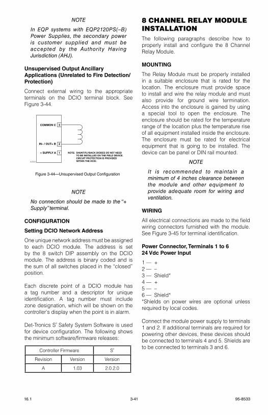
3-41 95-853316.1
noTe
In eQP systems with eQP2120PS(–B) Power Supplies, the secondary power is customer supplied and must be accepted by the Authority Having Jurisdiction (AHJ).
Unsupervised Output Ancillary Applications (Unrelated to Fire Detection/Protection)
Connect external wiring to the appropriate terminals on the DCIO terminal block. see Figure 3-44.
noTe
no connection should be made to the “+ Supply” terminal.
CONFIGURATION
Setting DCIO Network Address
One unique network address must be assigned to each DCIO module. the address is set by the 8 switch DIP assembly on the DCIO module. the address is binary coded and is the sum of all switches placed in the “closed” position.
each discrete point of a DCIO module has a tag number and a descriptor for unique identification. A tag number must include zone designation, which will be shown on the controller's display when the point is in alarm.
Det-tronics s³ safety system software is used for device configuration. the following shows the minimum software/firmware releases:
8 cHAnnel relAy MoDUle InStAllAtIonthe following paragraphs describe how to properly install and configure the 8 Channel relay Module.
MOUNTING
the relay Module must be properly installed in a suitable enclosure that is rated for the location. the enclosure must provide space to install and wire the relay module and must also provide for ground wire termination. Access into the enclosure is gained by using a special tool to open the enclosure. the enclosure should be rated for the temperature range of the location plus the temperature rise of all equipment installed inside the enclosure. the enclosure must be rated for electrical equipment that is going to be installed. the device can be panel or DIN rail mounted.
noTe
It is recommended to maintain a minimum of 4 inches clearance between the module and other equipment to provide adequate room for wiring and ventilation.
WIRING
All electrical connections are made to the field wiring connectors furnished with the module. see Figure 3-45 for terminal identification.
Power Connector, Terminals 1 to 6 24 Vdc Power Input
1 — +2 — –3 — shield*4 — +5 — –6 — shield**shields on power wires are optional unless required by local codes.
Connect the module power supply to terminals 1 and 2. If additional terminals are required for powering other devices, these devices should be connected to terminals 4 and 5. shields are to be connected to terminals 3 and 6.
Figure 3-44—Unsupervised Output Configuration
+ SUPPLY A
IN– / OUT+ B
COMMON C
1
2
3
NOTE: SHUNT/FLYBACK DIODES DO NOT NEED TO BE INSTALLED ON THE FIELD DEVICE. CIRCUIT PROTECTION IS PROVIDED WITHIN THE DCIO. A2323
Controller Firmware s³
revision version version
A 1.03 2.0.2.0
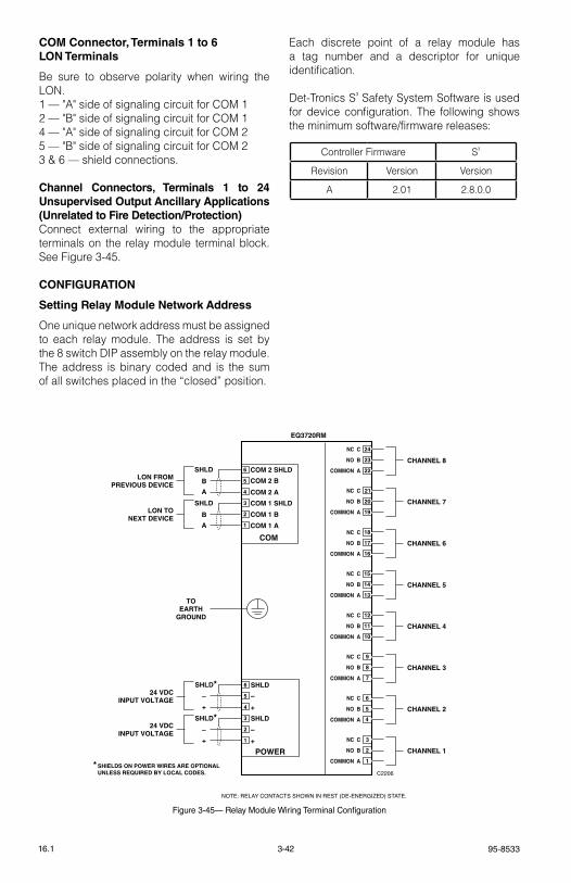
95-85333-4216.1
COM Connector, Terminals 1 to 6 LON Terminals
Be sure to observe polarity when wiring the lON.1 — "A" side of signaling circuit for COM 12 — "B" side of signaling circuit for COM 14 — "A" side of signaling circuit for COM 25 — "B" side of signaling circuit for COM 23 & 6 — shield connections.
Channel Connectors, Terminals 1 to 24 Unsupervised Output Ancillary Applications (Unrelated to Fire Detection/Protection)Connect external wiring to the appropriate terminals on the relay module terminal block. see Figure 3-45.
CONFIGURATION
Setting Relay Module Network Address
One unique network address must be assigned to each relay module. the address is set by the 8 switch DIP assembly on the relay module. the address is binary coded and is the sum of all switches placed in the “closed” position.
each discrete point of a relay module has a tag number and a descriptor for unique identification.
Det-tronics s³ safety system software is used for device configuration. the following shows the minimum software/firmware releases:
CHANNEL 8
CHANNEL 7
CHANNEL 6
CHANNEL 5
CHANNEL 4
CHANNEL 3
CHANNEL 2
CHANNEL 1
COM
6
5
4
3
2
1
COM 2 SHLD
COM 2 B
COM 2 A
COM 1 SHLD
COM 1 B
COM 1 A
SHLD
B
A
SHLD
B
A
LON FROMPREVIOUS DEVICE
LON TONEXT DEVICE
POWER
6
5
4
3
2
1
SHLD
–
+
SHLD
–
+
SHLD*–
+
SHLD*–
+
24 VDCINPUT VOLTAGE
24 VDCINPUT VOLTAGE
EQ3720RM
TOEARTH
GROUND
C2206
COMMON A
NO B
NC C
COMMON A
NO B
NC C
COMMON A
NO B
NC C
COMMON A
NO B
NC C
COMMON A
NO B
NC C
COMMON A
NO B
NC C
COMMON A
NO B
NC C
COMMON A
NO B
NC C
1
2
3
4
5
6
7
8
9
10
11
12
13
14
15
16
17
18
19
20
21
22
23
24
* SHIELDS ON POWER WIRES ARE OPTIONAL UNLESS REQUIRED BY LOCAL CODES.
NOTE: RELAY CONTACTS SHOWN IN REST (DE-ENERGIZED) STATE.
Figure 3-45— Relay Module Wiring Terminal Configuration
Controller Firmware s³
revision version version
A 2.01 2.8.0.0
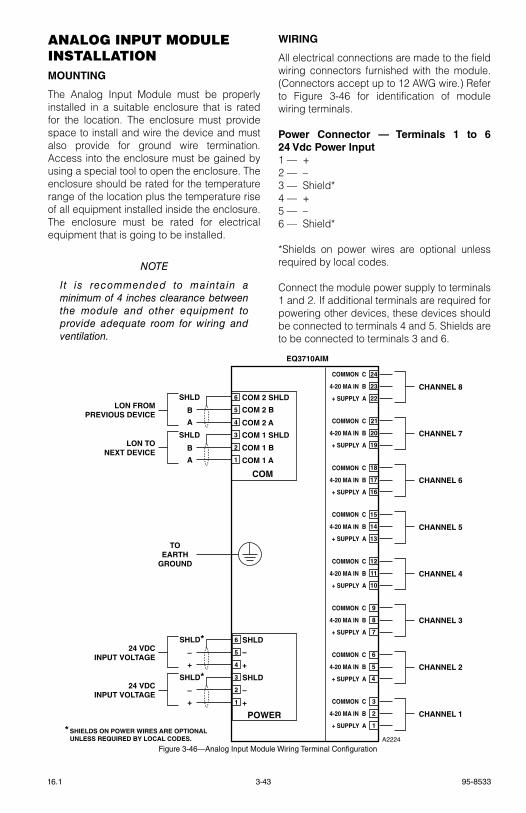
3-43 95-853316.1
AnAlog InpUt MoDUle InStAllAtIonMOUNTING
the Analog Input Module must be properly installed in a suitable enclosure that is rated for the location. the enclosure must provide space to install and wire the device and must also provide for ground wire termination. Access into the enclosure must be gained by using a special tool to open the enclosure. the enclosure should be rated for the temperature range of the location plus the temperature rise of all equipment installed inside the enclosure. the enclosure must be rated for electrical equipment that is going to be installed.
noTe
It is recommended to maintain a minimum of 4 inches clearance between the module and other equipment to provide adequate room for wiring and ventilation.
WIRING
All electrical connections are made to the field wiring connectors furnished with the module. (Connectors accept up to 12 AWg wire.) refer to Figure 3-46 for identification of module wiring terminals.
Power Connector — Terminals 1 to 6 24 Vdc Power Input1 — +2 — –3 — shield*4 — +5 — –6 — shield*
*shields on power wires are optional unless required by local codes.
Connect the module power supply to terminals 1 and 2. If additional terminals are required for powering other devices, these devices should be connected to terminals 4 and 5. shields are to be connected to terminals 3 and 6.
CHANNEL 8
CHANNEL 7
CHANNEL 6
CHANNEL 5
CHANNEL 4
CHANNEL 3
CHANNEL 2
CHANNEL 1
COM
6
5
4
3
2
1
COM 2 SHLD
COM 2 B
COM 2 A
COM 1 SHLD
COM 1 B
COM 1 A
SHLD
B
A
SHLD
B
A
LON FROMPREVIOUS DEVICE
LON TONEXT DEVICE
POWER
6
5
4
3
2
1
SHLD
–
+
SHLD
–
+
SHLD*–
+
SHLD*–
+
24 VDCINPUT VOLTAGE
24 VDCINPUT VOLTAGE
EQ3710AIM
TOEARTH
GROUND
A2224
+ SUPPLY A
4-20 MA IN B
COMMON C
+ SUPPLY A
4-20 MA IN B
COMMON C
+ SUPPLY A
4-20 MA IN B
COMMON C
+ SUPPLY A
4-20 MA IN B
COMMON C
+ SUPPLY A
4-20 MA IN B
COMMON C
+ SUPPLY A
4-20 MA IN B
COMMON C
+ SUPPLY A
4-20 MA IN B
COMMON C
+ SUPPLY A
4-20 MA IN B
COMMON C
1
2
3
4
5
6
7
8
9
10
11
12
13
14
15
16
17
18
19
20
21
22
23
24
* SHIELDS ON POWER WIRES ARE OPTIONAL UNLESS REQUIRED BY LOCAL CODES.
Figure 3-46—Analog Input Module Wiring Terminal Configuration
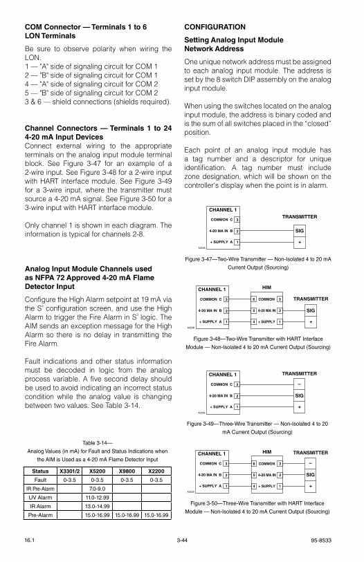
95-85333-4416.1
COM Connector — Terminals 1 to 6 LON Terminals
Be sure to observe polarity when wiring the lON.1 — "A" side of signaling circuit for COM 12 — "B" side of signaling circuit for COM 14 — "A" side of signaling circuit for COM 25 — "B" side of signaling circuit for COM 23 & 6 — shield connections (shields required).
Channel Connectors — Terminals 1 to 24 4-20 mA Input DevicesConnect external wiring to the appropriate terminals on the analog input module terminal block. see Figure 3-47 for an example of a 2-wire input. see Figure 3-48 for a 2-wire input with HArt interface module. see Figure 3-49 for a 3-wire input, where the transmitter must source a 4-20 mA signal. see Figure 3-50 for a 3-wire input with HArt interface module.
Only channel 1 is shown in each diagram. the information is typical for channels 2-8.
Analog Input Module Channels used as NFPA 72 Approved 4-20 mA Flame Detector Input
Configure the High Alarm setpoint at 19 mA via the s³ configuration screen, and use the High Alarm to trigger the Fire Alarm in s³ logic. the AIM sends an exception message for the High Alarm so there is no delay in transmitting the Fire Alarm.
Fault indications and other status information must be decoded in logic from the analog process variable. A five second delay should be used to avoid indicating an incorrect status condition while the analog value is changing between two values. see table 3-14.
CONFIGURATION
Setting Analog Input Module Network Address
One unique network address must be assigned to each analog input module. the address is set by the 8 switch DIP assembly on the analog input module.
When using the switches located on the analog input module, the address is binary coded and is the sum of all switches placed in the “closed” position.
each point of an analog input module has a tag number and a descriptor for unique identification. A tag number must include zone designation, which will be shown on the controller's display when the point is in alarm.
+ SUPPLY A
4-20 MA IN B
COMMON C
CHANNEL 1
1
2
3
A2235
+
SIG
TRANSMITTER
Figure 3-47—Two-Wire Transmitter — Non-Isolated 4 to 20 mA
Current Output (Sourcing)
+ SUPPLY A
4-20 MA IN B
COMMON C
CHANNEL 1
1
2
3
A2236
+
–
SIG
TRANSMITTER
Figure 3-49—Three-Wire Transmitter — Non-Isolated 4 to 20
mA Current Output (Sourcing)
+ SUPPLY A
4-20 MA IN B
COMMON C
CHANNEL 1
1
2
3
+ SUPPLY
4-20 MA IN
COMMON
HIM
14
25
36
A2238
+
SIG
TRANSMITTER
Figure 3-48—Two-Wire Transmitter with HART Interface
Module — Non-Isolated 4 to 20 mA Current Output (Sourcing)
+ SUPPLY A
4-20 MA IN B
COMMON C
CHANNEL 1
1
2
3
A2239
+
–
SIG
TRANSMITTER
+ SUPPLY
4-20 MA IN
COMMON
HIM
14
25
36
Figure 3-50—Three-Wire Transmitter with HART Interface
Module — Non-Isolated 4 to 20 mA Current Output (Sourcing)
Table 3-14—
Analog Values (in mA) for Fault and Status Indications when
the AIM is Used as a 4-20 mA Flame Detector Input
Status X3301/2 X5200 X9800 X2200
Fault 0-3.5 0-3.5 0-3.5 0-3.5
IR Pre-Alarm 7.0-9.0
UV Alarm 11.0-12.99
IR Alarm 13.0-14.99
Pre-Alarm 15.0-16.99 15.0-16.99 15.0-16.99

3-45 95-853316.1
Det-tronics s³ safety system software is used for device configuration. the following tables show the minimum software/firmware releases:
gAS Detector locAtIon AnD InStAllAtIongas detection devices must be properly located to provide maximum protection. Determining the proper number of devices and placement varies depending on the specific requirements of the area of protection.
the following should be considered when locating a gas detection device:
1. gas type. If it is lighter than air (acetylene, hydrogen, methane, etc.), place the sensor above the potential source. Place the sensor close to the floor for gases that are heavier than air (benzene, butane, butylene, propane, hexane, pentane, etc.) or for vapors resulting from flammable liquid spills.
noTe
Air currents can cause a gas that is heavier than air to rise. Also, if the gas is hotter than ambient air, it could also rise.
2. How rapidly will the gas diffuse into the air? select a location for the sensor as close as possible to the anticipated source of a gas leak.
3. ventilation characteristics. Air movement will cause gas to accumulate more heavily in one area than another. the devices should be placed in areas where the most concentrated accumulation of gas is anticipated.
4. Devices should be pointed down to prevent the buildup of moisture or contaminants on the filter.
5. Devices must be accessible for testing and calibration.
*for part number 007606-002
For Gas Applications
Controller Firmware* AIM s³
rev. version rev. version version
B 3.06 B 1.02 2.9.1.1
*for part number 008983-001
For Flame Applications
Controller Firmware* AIM s³
rev. version rev. version version
C 5.52 D 1.07 4.0.0.0

95-85333-4616.1
noTe
The use of the Sensor Separation Kit will be required in some installations.
ENVIRONMENTS AND SUBSTANCES THAT AFFECT GAS DETECTOR PERFORMANCE
Catalytic sensors should be located where they are safe from potential sources of contamination that can cause a decrease in the sensitivity of the device including:
A. substances that can clog the pores of the flame arrestor and reduce the gas diffusion rate to the sensor including:
Dirt and oil, corrosive substances such as Cl2 (Chlorine) or HCl, paint overspray, or residue from cleaning solutions that can clog the flame arrestor.
noTe
A dust cover should be installed to protect the flame arrester whenever these conditions exist.
B. substances that cover or tie up the active sites on the catalytic surface of the active sensing element such as volatile metal organics, gases, or vapors of hydrides, and volatile compounds containing phosphorous, boron, silicone, etc.
Examples:
rtv silicone sealants silicone oils and greases tetraethyl lead Phosphine Diborane silane trimethyl chlorsilane Hydrogen fluoride Boron trifluoride Phosphate esters
C. Materials that remove the catalytic metals from the active element of the sensor. some substances react with the catalytic metal forming a volatile compound that can erode the metal from the surface of the sensor’s active element.
Halogens and compounds containing halogen are materials of this nature and others include:
Examples:
Chlorine Bromine Iodine Hydrogen Chloride, Bromide or Iodide Organic halides: trichloroethylene Dichlorobenzene vinyl chloride Freons Halon 1301 (Bromotrifluoromethane).
noTe
Brief exposure to these materials can temporarily increase sensor sensitivity due to the surface of the active element being etched. Prolonged exposure continues this process until the sensitivity of the sensor is degraded, resulting in shortened sensor life.
D. exposure to high concentrations of combustible gases for extended periods of time can stress the sensing element and seriously affect its performance.
the degree of damage to the sensor is determined by a combination of contaminant type, contaminant concentration in the atmosphere, and the length of time the sensor is exposed.
noTe
If a sensor has been exposed to a contaminant or a high level of combustible gas, it should be calibrated at the time of exposure. An additional calibration a few days later should be performed to determine whether a significant shift in sensitivity has occurred. If necessary, sensor should be replaced.
noTe
A combination of accessories such as rain shields and dust covers is not recommended and can result in slow response to a gas leak.
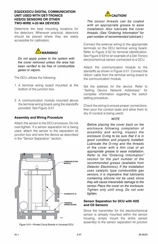
3-47 95-853316.1
EQ22XXDCU DIGITAL COMMUNICATION UNIT USED WITH DET-TRONICS H2S/O2 SENSORS OR OTHER TWO-WIRE 4-20 MA DEVICES
Determine the best mounting locations for the detectors. Whenever practical, detectors should be placed where they are easily accessible for calibration.
WARNING!
Do not apply power to the system with the cover removed unless the area has been verified to be free of combustible gases or vapors.
the DCU utilizes the following:
1. A terminal wiring board mounted at the bottom of the junction box.
2. A communication module mounted above the terminal wiring board using the standoffs provided. see Figure 3-51.
Assembly and Wiring Procedure
Attach the sensor to the DCU enclosure. Do not over-tighten. If a sensor separation kit is being used, attach the sensor to the separation kit junction box and wire the device as described in the “sensor separation” section.
CAUTION!
The sensor threads can be coated with an appropriate grease to ease installation. Also lubricate the cover threads. (See “ordering Information” for part number of recommended lubricant.)
Connect the external wiring to the appropriate terminals on the DCU terminal wiring board. refer to Figure 3-52 for terminal identification. see Figure 3-53 for an example of a Det-tronics electrochemical sensor connected to a DCU.
Attach the communication module to the standoffs as shown in Figure 3-51. Connect the ribbon cable from the terminal wiring board to the communication module.
set the address for the device. refer to “setting Device Network Addresses” for complete information regarding the switch setting procedure.
Check the wiring to ensure proper connections, then pour the conduit seals and allow them to dry (if conduit is being used).
noTe
Before placing the cover back on the enclosure fol lowing completion of assembly and wiring, inspect the enclosure o-ring to be sure that it is in good condition and properly installed. Lubricate the o-ring and the threads of the cover with a thin coat of an appropriate grease to ease installation. Refer to the “ordering Information” section for the part number of the recommended grease (available from Detector electronics). If the installation uses catalytic type combustible gas sensors, it is imperative that lubricants containing silicone not be used, since they will cause irreversible damage to the sensor. Place the cover on the enclosure. Tighten only until snug. Do not over tighten.
Sensor Separation for DCU with H2S and O2 Sensors
since the transmitter for the electrochemical sensor is already mounted within the sensor housing, simply mount the entire sensor assembly to the sensor separation kit junction
A1571
COMMUNICATIONMODULE
STANDOFFS (4)
TERMINAL WIRING BOARD
Figure 3-51—Printed Circuit Boards in Universal DCU
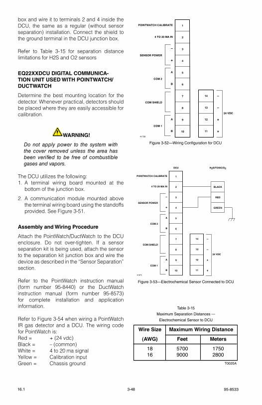
95-85333-4816.1
box and wire it to terminals 2 and 4 inside the DCU, the same as a regular (without sensor separation) installation. Connect the shield to the ground terminal in the DCU junction box.
refer to table 3-15 for separation distance limitations for H2s and O2 sensors
EQ22XXDCU DIGITAL COMMUNICA-TION UNIT USED WITH POINTWATCH/DUCTWATCH
Determine the best mounting location for the detector. Whenever practical, detectors should be placed where they are easily accessible for calibration.
WARNING!
Do not apply power to the system with the cover removed unless the area has been verified to be free of combustible gases and vapors.
the DCU utilizes the following:1. A terminal wiring board mounted at the
bottom of the junction box.
2. A communication module mounted above the terminal wiring board using the standoffs provided. see Figure 3-51.
Assembly and Wiring Procedure
Attach the PointWatch/DuctWatch to the DCU enclosure. Do not over-tighten. If a sensor separation kit is being used, attach the sensor to the separation kit junction box and wire the device as described in the “sensor separation” section.
refer to the PointWatch instruction manual (form number 95-8440) or the DuctWatch instruction manual (form number 95-8573) for complete installation and application information.
refer to Figure 3-54 when wiring a PointWatch Ir gas detector and a DCU. the wiring code for PointWatch is:red = + (24 vdc)Black = – (common)White = 4 to 20 ma signalYellow = Calibration inputgreen = Chassis ground
1
2
3
4
5
6
7
8
9
10
14
13
12
11
–
–
+
+
24 VDC
POINTWATCH CALIBRATE
4 TO 20 MA IN
–
+
A
B
A
B
SENSOR POWER
COM 2
COM SHIELD
COM 1
A1726
Figure 3-52—Wiring Configuration for DCU
1
2
3
4
5
6
7
8
9
10
BLACK
RED
GREEN
DCU H2S/TOXIC/O2
14
13
12
11
–
–
+
+
24 VDC
POINTWATCH CALIBRATE
4 TO 20 MA IN
–
+
A
B
A
B
SENSOR POWER
COM 2
COM SHIELD
COM 1
A1875
Figure 3-53—Electrochemical Sensor Connected to DCU
T0020A
Wire Size Maximum Wiring Distance
(AWG) Feet Meters
18 5700 175016 9000 2800
Table 3-15
Maximum Separation Distances —
Electrochemical Sensor to DCU
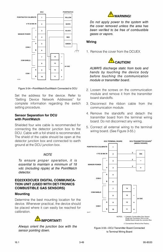
3-49 95-853316.1
set the address for the device. refer to “setting Device Network Addresses” for complete information regarding the switch setting procedure.
Sensor Separation for DCU with PointWatch
shielded four wire cable is recommended for connecting the detector junction box to the DCU. Cable with a foil shield is recommended. the shield of the cable should be open at the detector junction box and connected to earth ground at the DCU junction box.
noTe
To ensure proper operat ion, i t is essential to maintain a minimum of 18 vdc (including ripple) at the PointWatch detector.
EQ22XXDCUEX DIGITAL COMMUNICA-TION UNIT (USED WITH DET-TRONICS COMBUSTIBLE GAS SENSORS)
Mounting
Determine the best mounting location for the device. Whenever practical, the device should be placed where it can easily be reached for calibration.
IMPORTANT!
Always orient the junction box with the sensor pointing down.
WARNING!
Do not apply power to the system with the cover removed unless the area has been verified to be free of combustible gases or vapors.
Wiring
1. remove the cover from the DCUeX.
CAUTION!
ALWAYS discharge static from tools and hands by touching the device body before touching the communication module or transmitter board.
2. loosen the screws on the communication module and remove it from the transmitter board standoffs.
3. Disconnect the ribbon cable from the communication module.
4. remove the standoffs and detach the transmitter board from the terminal wiring board. Do not disconnect any wiring.
5. Connect all external wiring to the terminal wiring board. (see Figure 3-55.)
1
2
3
4
5
6
7
8
9
10
YELLOW
WHITE
BLACK
RED
GREEN
DCU POINTWATCH
14
13
12
11
–
–
+
+
24 VDC
POINTWATCH CALIBRATE
4 TO 20 MA IN
–
+
A
B
A
B
SENSOR POWER
COM 2
COM SHIELD
COM 1
A1876
Figure 3-54—PointWatch/DuctWatch Connected to DCU
1
2
3
4
5
6
7
8
9
10
SIG
–
+
DCU TERMINAL BOARD DCU TRANSMITTER BOARD1(MIDDLE BOARD)
14
13
12
11
–
–
+
+
24 VDC
POINTWATCH CALIBRATE
4 TO 20 MA IN
–
+
A
B
A
B
SENSOR POWER
COM 2
COM SHIELD
COM 1
B1877
NOTES: 1 Catalytic Combustible Gas Sensor Plugs into Connector Pins on the Middle Board inside the Junction Box.
2 Connections Wired at the Factory.
2
2
2
Figure 3-55—DCU Transmitter Board Connected
to Terminal Wiring Board
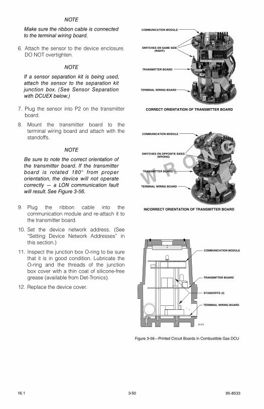
95-85333-5016.1
noTe
Make sure the ribbon cable is connected to the terminal wiring board.
6. Attach the sensor to the device enclosure. DO NOt overtighten.
noTe
If a sensor separation kit is being used, attach the sensor to the separation kit junction box. (See Sensor Separation with DCUeX below.)
7. Plug the sensor into P2 on the transmitter board.
8. Mount the transmitter board to the terminal wiring board and attach with the standoffs.
noTe
Be sure to note the correct orientation of the transmitter board. If the transmitter board is rotated 180° from proper orientation, the device will not operate correctly — a Lon communication fault will result. See Figure 3-56.
9. Plug the ribbon cable into the communication module and re-attach it to the transmitter board.
10. set the device network address. (see “setting Device Network Addresses” in this section.)
11. Inspect the junction box O-ring to be sure that it is in good condition. lubricate the O-ring and the threads of the junction box cover with a thin coat of silicone-free grease (available from Det-tronics).
12. replace the device cover.
W R O N G
COMMUNICATION MODULE
TRANSMITTER BOARD
STANDOFFS (4)
TERMINAL WIRING BOARD
COMMUNICATION MODULE
SWITCHES ON SAME SIDE(RIGHT)
TRANSMITTER BOARD
TERMINAL WIRING BOARD
CORRECT ORIENTATION OF TRANSMITTER BOARD
COMMUNICATION MODULE
SWITCHES ON OPPOSITE SIDES(WRONG)
TRANSMITTER BOARD
TERMINAL WIRING BOARD
INCORRECT ORIENTATION OF TRANSMITTER BOARD
B1570
Figure 3-56—Printed Circuit Boards in Combustible Gas DCU
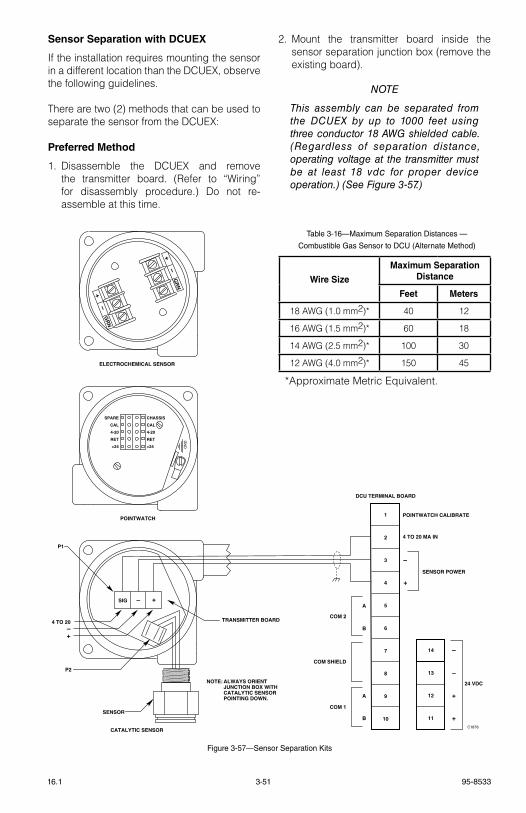
3-51 95-853316.1
Sensor Separation with DCUEX
If the installation requires mounting the sensor in a different location than the DCUeX, observe the following guidelines.
there are two (2) methods that can be used to separate the sensor from the DCUeX:
Preferred Method
1. Disassemble the DCUeX and remove the transmitter board. (refer to “Wiring” for disassembly procedure.) Do not re-assemble at this time.
2. Mount the transmitter board inside the sensor separation junction box (remove the existing board).
noTe
This assembly can be separated from the DCUeX by up to 1000 feet using three conductor 18 AWG shielded cable. (Regardless of separation distance, operating voltage at the transmitter must be at least 18 vdc for proper device operation.) (See Figure 3-57.)
Figure 3-57—Sensor Separation Kits
SENSOR
CATALYTIC SENSOR
ELECTROCHEMICAL SENSOR
TRANSMITTER BOARD
P1
P2
4 TO 20–+
C1878
POINTWATCH
GN
D
SPARE
CAL
4-20
RET
+24
CHASSIS
CAL
4-20
RET
+24
+
GR
N–
+
GR
N–
NOTE: ALWAYS ORIENT JUNCTION BOX WITH CATALYTIC SENSOR POINTING DOWN.
1
2
3
4
5
6
7
8
9
10
DCU TERMINAL BOARD
14
13
12
11
–
–
+
+
24 VDC
COM 2
COM SHIELD
COM 1
POINTWATCH CALIBRATE
4 TO 20 MA IN
–
+
SENSOR POWER
A
B
B
A
SIG – +
Wire Size
Maximum Separation Distance
Feet Meters
18 AWg (1.0 mm2)* 40 12
16 AWg (1.5 mm2)* 60 18
14 AWg (2.5 mm2)* 100 30
12 AWg (4.0 mm2)* 150 45
*Approximate Metric equivalent.
Table 3-16—Maximum Separation Distances —
Combustible Gas Sensor to DCU (Alternate Method)
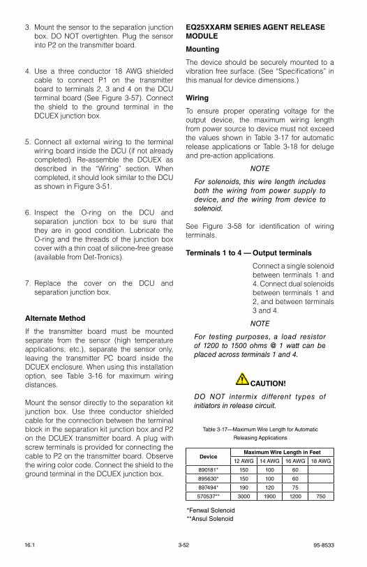
95-85333-5216.1
3. Mount the sensor to the separation junction box. DO NOt overtighten. Plug the sensor into P2 on the transmitter board.
4. Use a three conductor 18 AWg shielded cable to connect P1 on the transmitter board to terminals 2, 3 and 4 on the DCU terminal board (see Figure 3-57). Connect the shield to the ground terminal in the DCUeX junction box.
5. Connect all external wiring to the terminal wiring board inside the DCU (if not already completed). re-assemble the DCUeX as described in the “Wiring” section. When completed, it should look similar to the DCU as shown in Figure 3-51.
6. Inspect the O-ring on the DCU and separation junction box to be sure that they are in good condition. lubricate the O-ring and the threads of the junction box cover with a thin coat of silicone-free grease (available from Det-tronics).
7. replace the cover on the DCU and separation junction box.
Alternate Method
If the transmitter board must be mounted separate from the sensor (high temperature applications, etc.), separate the sensor only, leaving the transmitter PC board inside the DCUeX enclosure. When using this installation option, see table 3-16 for maximum wiring distances.
Mount the sensor directly to the separation kit junction box. Use three conductor shielded cable for the connection between the terminal block in the separation kit junction box and P2 on the DCUeX transmitter board. A plug with screw terminals is provided for connecting the cable to P2 on the transmitter board. Observe the wiring color code. Connect the shield to the ground terminal in the DCUeX junction box.
EQ25XXARM SERIES AGENT RELEASE MODULE
Mounting
the device should be securely mounted to a vibration free surface. (see “specifications” in this manual for device dimensions.)
Wiring
to ensure proper operating voltage for the output device, the maximum wiring length from power source to device must not exceed the values shown in table 3-17 for automatic release applications or table 3-18 for deluge and pre-action applications.
noTe
For solenoids, this wire length includes both the wiring from power supply to device, and the wiring from device to solenoid.
see Figure 3-58 for identification of wiring terminals.
Terminals 1 to 4 — Output terminals
Connect a single solenoid between terminals 1 and 4. Connect dual solenoids between terminals 1 and 2, and between terminals 3 and 4.
noTe
For testing purposes, a load resistor of 1200 to 1500 ohms @ 1 watt can be placed across terminals 1 and 4.
CAUTION!
Do noT intermix different types of initiators in release circuit.
Table 3-17—Maximum Wire Length for Automatic
Releasing Applications
*Fenwal Solenoid**Ansul Solenoid
DeviceMaximum Wire Length in Feet
12 AWG 14 AWG 16 AWG 18 AWG
890181* 150 100 60
895630* 150 100 60
897494* 190 120 75
570537** 3000 1900 1200 750
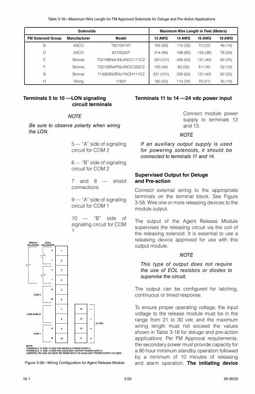
3-53 95-853316.1
Terminals 5 to 10 —LON signaling circuit terminals
noTe
Be sure to observe polarity when wiring the Lon.
5 — “A” side of signaling circuit for COM 2
6 — “B” side of signaling circuit for COM 2
7 and 8 — shield connections
9 — “A” side of signaling circuit for COM 1
10 — “B” side of signaling circuit for COM 1
Terminals 11 to 14 —24 vdc power input
Connect module power supply to terminals 12 and 13.
noTe
If an auxiliary output supply is used for powering solenoids, it should be connected to terminals 11 and 14.
Supervised Output for Deluge and Pre-action
Connect external wiring to the appropriate terminals on the terminal block. see Figure 3-58. Wire one or more releasing devices to the module output.
the output of the Agent release Module supervises the releasing circuit via the coil of the releasing solenoid. It is essential to use a releasing device approved for use with this output module.
noTe
This type of output does not require the use of eoL resistors or diodes to supervise the circuit.
the output can be configured for latching, continuous or timed response.
to ensure proper operating voltage, the input voltage to the release module must be in the range from 21 to 30 vdc and the maximum wiring length must not exceed the values shown in table 3-18 for deluge and pre-action applications. Per FM Approval requirements, the secondary power must provide capacity for a 90 hour minimum standby operation followed by a minimum of 10 minutes of releasing and alarm operation. The initiating device
Solenoids Maximum Wire Length in Feet (Meters)
FM Solenoid Group Manufacturer Model 12 AWG 14 AWG 16 AWG 18 AWG
B AsCO t8210A107 183 (56) 115 (35) 72 (22) 46 (14)
D AsCO 8210g207 314 (96) 198 (60) 124 (38) 78 (24)
e skinner 73218BN4UNlvNOC111C2 331(101) 208 (63) 131 (40) 82 (25)
F skinner 73212BN4tNlvNOC322C2 130 (40) 82 (25) 51 (16) 32 (10)
g skinner 71395sN2eNJ1NOH111C2 331 (101) 208 (63) 131 (40) 82 (25)
H viking 11601 180 (55) 110 (34) 70 (21) 45 (14)
Table 3-18—Maximum Wire Length for FM Approved Solenoids for Deluge and Pre-Action Applications
1
2
3
4
5
6
7
8
9
10
1
2
3
4
EXPLOSIVE INITIATOR OPTION
DUALSOLENOIDS
14
13
12
11
–
–
+
+
24 VDC
+
–
+
–
A
B
A
B
SINGLESOLENOID
COM 2
COM SHIELD
COM 1
NOTE:TERMINALS 12 AND 13 ARE FOR MODULE POWER SUPPLY.TERMINALS 11 AND 14 ARE FOR AUXILIARY OUTPUT POWER SUPPLY.JUMPERS JP2 AND JP3 MUST BE REMOVED IF AN AUXILIARY POWER SUPPLY IS USED.
NOTES:1. JUMPER JP1 MUST BE REMOVED IF EXPLOSIVE INITIATOR IS USED.
2. RESISTOR IS USED TO COMPENSATE FOR 10 OHMS CIRCUIT RESISTANCE. RESISTOR MUST BE RATED 1 WATT MINIMUM (WIRE-WOUND RESISTOR PREFERRED). WHEN MEASURING THE TOTAL RELEASE CIRCUIT RESISTANCE, USE AN OHM METER WITH A CURRENT OUTPUT OF 10 MA MAXIMUM.
3. MAXIMUM NUMBER OF EXPLOSIVE INITIATORS PER CIRCUIT IS 12. EACH CIRCUIT MUST NOT EXCEED 10 OHMS INCLUDING CABLE RESISTANCE. B1900
SEE NOTE 2.
Figure 3-58—Wiring Configuration for Agent Release Module
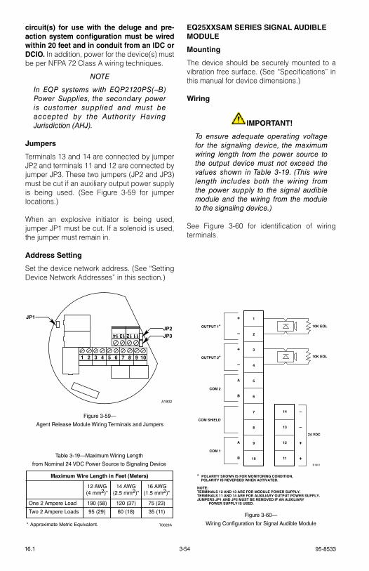
95-85333-5416.1
circuit(s) for use with the deluge and pre-action system configuration must be wired within 20 feet and in conduit from an IDC or DCIO. In addition, power for the device(s) must be per NFPA 72 Class A wiring techniques.
noTe
In eQP systems with eQP2120PS(–B) Power Supplies, the secondary power is customer supplied and must be accepted by the Authority Having Jurisdiction (AHJ).
Jumpers
terminals 13 and 14 are connected by jumper JP2 and terminals 11 and 12 are connected by jumper JP3. these two jumpers (JP2 and JP3) must be cut if an auxiliary output power supply is being used. (see Figure 3-59 for jumper locations.)
When an explosive initiator is being used, jumper JP1 must be cut. If a solenoid is used, the jumper must remain in.
Address Setting
set the device network address. (see “setting Device Network Addresses” in this section.)
EQ25XXSAM SERIES SIGNAL AUDIBLE MODULE
Mounting
the device should be securely mounted to a vibration free surface. (see “specifications” in this manual for device dimensions.)
Wiring
IMPORTANT!
To ensure adequate operating voltage for the signaling device, the maximum wiring length from the power source to the output device must not exceed the values shown in Table 3-19. (This wire length includes both the wiring from the power supply to the signal audible module and the wiring from the module to the signaling device.)
see Figure 3-60 for identification of wiring terminals.
9 107 85 63 41 2
1314 1112
JP1
JP2JP3
A1902
Figure 3-59—
Agent Release Module Wiring Terminals and Jumpers
Maximum Wire Length in Feet (Meters)
12 AWG 14 AWG 16 AWG(4 mm2)* (2.5 mm2)* (1.5 mm2)*
One 2 Ampere Load 190 (58) 120 (37) 75 (23)Two 2 Ampere Loads 95 (29) 60 (18) 35 (11)
T0029A* Approximate Metric Equivalent.
Table 3-19—Maximum Wiring Length
from Nominal 24 VDC Power Source to Signaling Device
1
2
3
4
5
6
7
8
9
10
14
13
12
11
–
–
+
+
24 VDC
+
–
+
–
A
B
A
B
OUTPUT 1*
OUTPUT 2*
COM 2
COM SHIELD
COM 1
* POLARITY SHOWN IS FOR MONITORING CONDITION, POLARITY IS REVERSED WHEN ACTIVATED.
NOTE:TERMINALS 12 AND 13 ARE FOR MODULE POWER SUPPLY.TERMINALS 11 AND 14 ARE FOR AUXILIARY OUTPUT POWER SUPPLY.JUMPERS JP1 AND JP2 MUST BE REMOVED IF AN AUXILIARY POWER SUPPLY IS USED.
B1901
10K EOL
10K EOL
Figure 3-60—
Wiring Configuration for Signal Audible Module
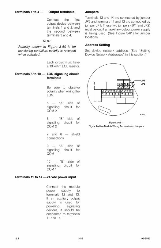
3-55 95-853316.1
Terminals 1 to 4 — Output terminals
Connect the first output device between terminals 1 and 2, and the second between terminals 3 and 4.
noTe
Polarity shown in Figure 3-60 is for monitoring condition; polarity is reversed when activated.
each circuit must have a 10 kohm eOl resistor.
Terminals 5 to 10 — LON signaling circuit terminals
Be sure to observe polarity when wiring the lON.
5 — “A” side of signaling circuit for COM 2
6 — “B” side of signaling circuit for COM 2
7 and 8 — shield connections
9 — “A” side of signaling circuit for COM 1
10 — “B” side of signaling circuit for COM 1
Terminals 11 to 14 — 24 vdc power input
Connect the module power supply to terminals 12 and 13. If an auxiliary output supply is used for powering signaling devices, it should be connected to terminals 11 and 14.
Jumpers
terminals 13 and 14 are connected by jumper JP2 and terminals 11 and 12 are connected by jumper JP1. these two jumpers (JP1 and JP2) must be cut if an auxiliary output power supply is being used. (see Figure 3-61) for jumper locations.
Address Setting
set device network address. (see “setting Device Network Addresses” in this section.)
9 107 85 63 41 2
1314 1112
JP1JP2
B1903
Figure 3-61—
Signal Audible Module Wiring Terminals and Jumpers
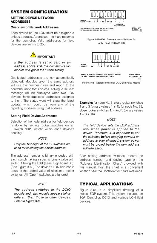
95-85333-5616.1
SySteM conFIgUrAtIon SETTING DEVICE NETWORK ADDRESSES
Overview of Network Addresses
each device on the lON must be assigned a unique address. Addresses 1 to 4 are reserved for the controller. valid addresses for field devices are from 5 to 250.
IMPORTANT
If the address is set to zero or an address above 250, the communication module will ignore the switch setting.
Duplicated addresses are not automatically detected. Modules given the same address will use the number given and report to the controller using that address. A "rogue Device" message will be displayed when two lON devices have duplicate addresses assigned to them. the status word will show the latest update, which could be from any of the reporting modules using that address.
Setting Field Device Addresses
selection of the node address for field devices is done by setting rocker switches on an 8 switch “DIP switch” within each device’s housing.
noTe
only the first eight of the 12 switches are used for selecting the device address.
the address number is binary encoded with each switch having a specific binary value with switch 1 being the lsB (least significant Bit). (see Figure 3-62) the device’s lON address is equal to the added value of all closed rocker switches. All “Open” switches are ignored.
noTe
The address switches in the DCIo module and relay module appear slightly different than those in other devices. Refer to Figure 3-63.
Example: for node No. 5, close rocker switches 1 and 3 (binary values 1 + 4); for node No. 25, close rocker switches 1, 4 and 5 (binary values 1 + 8 + 16).
noTe
The field device sets the Lon address only when power is applied to the device. Therefore, it is important to set the switches before applying power. If an address is ever changed, system power must be cycled before the new address will take effect.
After setting address switches, record the address number and device type on the “Address Identification Chart” provided with this manual. Post the chart in a convenient location near the Controller for future reference.
typIcAl ApplIcAtIonSFigure 3-64 is a simplified drawing of a typical eQP system. this system includes an eQP Controller, DCIO and various lON field devices.
1 2 3 4 5 6 7 8
1 2 4 8 16 32 64 128
ON
NODE ADDRESS EQUALS THE ADDED VALUEOF ALL CLOSED ROCKER SWITCHES
A2190
BINARYVALUE
CLOSED = ONOPEN = OFF
Figure 3-63—Address Switch for DCIO and Relay Module
1 2 3 4 5 6 7 8 1 2 3 4
1 2 4 8 16 32 64 128
OPEN OPEN
LEAVE INOPEN POSITION
NODE ADDRESS EQUALS THE ADDED VALUEOF ALL CLOSED ROCKER SWITCHES
A1557
BINARYVALUE
CLOSED = ONOPEN = OFF
Figure 3-62—Field Device Address Switches for
ARM, SAM, DCU and IDC
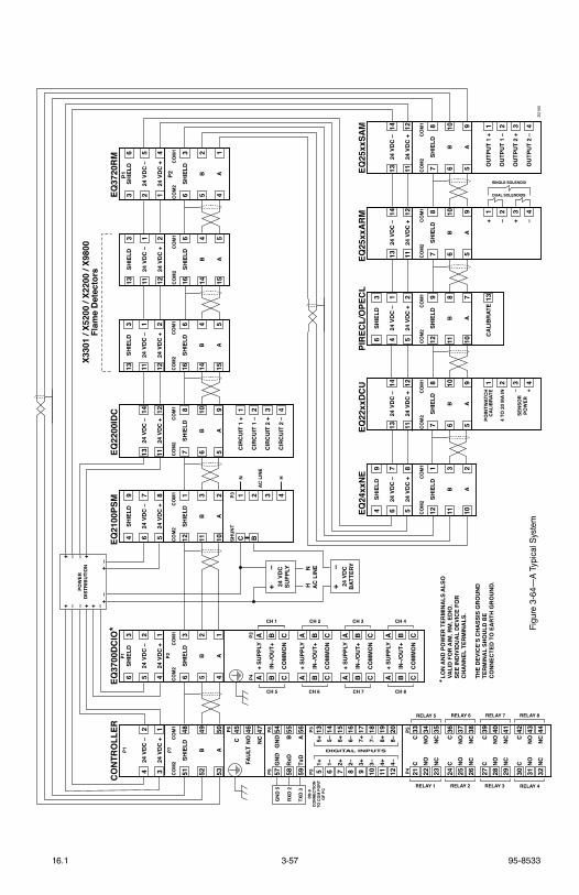
3-57 95-853316.1
EQ25
xxA
RM
24 V
DC
–13
14
24 V
DC
+11
12
B6
10
A5
9
–2
+3
–4
+1
SHIE
LD7
8C
OM
2C
OM
1
PIR
ECL/
OPE
CL
SHIE
LD6
3
24 V
DC
–4
1
24 V
DC
+5
2
B11
8
A10
7
CA
LIB
RAT
E13
SHIE
LD12
9C
OM
2C
OM
1
EQ22
xxD
CU
24 V
DC
–13
14
24 V
DC
+11
12
B6
10
A5
9
4 TO
20
MA
IN2
–3
+4
POIN
TWAT
CH
CA
LIB
RAT
E1
SHIE
LD7
8C
OM
2C
OM
1
EQ24
xxN
ESH
IELD
49
24 V
DC
–6
7
24 V
DC
+5
8
B11
3
A10
2
SHIE
LD12
1C
OM
2C
OM
1
EQ25
xxSA
M
24 V
DC
–13
14
24 V
DC
+11
12
B6
10
A5
9
OU
TPU
T 1
–2
OU
TPU
T 2
+3
OU
TPU
T 2
–4
OU
TPU
T 1
+1
SHIE
LD7
8C
OM
2C
OM
1
EQ22
00ID
CEQ
3720
RM
24 V
DC
–13
14
24 V
DC
+11
12
B6
10
A5
9
CIR
CU
IT 1
–2
CIR
CU
IT 2
+3
CIR
CU
IT 2
–4
CIR
CU
IT 1
+1
SHIE
LD7
8C
OM
2C
OM
1
EQ21
00PS
MSH
IELD
49
24 V
DC
–6
7
24 V
DC
+5
8
B11
3
A10
2
B2 3 4
C1
SHIE
LD12
1C
OM
2C
OM
1
SHU
NT
P3
AC
LIN
E
N H
SHIE
LD13
3
24 V
DC
–11
1
24 V
DC
+12
2
B14
4
A15
5
SHIE
LD16
6C
OM
2C
OM
1
SHIE
LD13
3
24 V
DC
–11
1
24 V
DC
+12
2
B14
4
A15
5
SHIE
LD16
6C
OM
2C
OM
1
X330
1 / X
5200
/ X2
200
/ X98
00Fl
ame
Det
ecto
rs
SHIE
LD3
6
24 V
DC
–2
5
24 V
DC
+1
4
B5
2
A4
1
SHIE
LD6
3C
OM
2C
OM
1
SINGLE SOLENOID
DUAL SOLENOIDS
EQ37
00D
CIO
*SH
IELD
63
24 V
DC
–5
2
24 V
DC
+4
1
B5
2
A4
1
SHIE
LD6
3C
OM
2C
OM
1
P1 P2
P3P4
IN–/
OU
T+B
B
CO
MM
ON
CC
+ SU
PPLY
AA
CH 1
CH 5
IN–/
OU
T+B
B
CO
MM
ON
CC
+ SU
PPLY
AA
CH 2
CH 6
IN–/
OU
T+B
B
CO
MM
ON
CC
+ SU
PPLY
AA
CH 3
CH 7
IN–/
OU
T+B
B
CO
MM
ON
CC
+ SU
PPLY
AA
CH 4
CH 8
CO
NTR
OLL
ER
24 V
DC
–4
2
24 V
DC
+3
1
B52
49
A53
50
TxD
A59
56
RxD
B58
55
GN
DG
ND
5754
SHIE
LD51
48C
OM
2C
OM
1
P1 P7
P9P8
P4P5
1+5+
513
1–5–
614
2+6+
715
2–6–
816
3+7+
917
3–7–
1018
4+8+
1119
4–8–
1220
P2P3
C45
NO
46N
C47P6
FAU
LT
GN
D 5
RXD
2
TXD
3D
B-9
CO
NN
ECTI
ON
TO C
OM
PO
RT
OF
PC
DIGITAL INPUTS
CC
2133
NO
NO
2234
NC
NC
2335
RELAY 5
RELAY 1
CC
2436
NO
NO
2537
NC
NC
2638
RELAY 6
RELAY 2
CC
2739
NO
NO
2840
NC
NC
2941
RELAY 7
RELAY 3
CC
3042
NO
NO
3143
NC
NC
3244
RELAY 8
RELAY 4
SEN
SOR
POW
ER
24 V
DC
SUPP
LY
+–
24 V
DC
BAT
TERY
+–
HN
AC
LIN
E
POW
ERD
ISTR
IBU
TIO
N+ +
++
+++ – –
––
–––
D21
00
P2P1
* LO
N A
ND
PO
WER
TER
MIN
ALS
ALS
O
VA
LID
FO
R A
IM, R
M, E
DIO
. S
EE IN
DIV
IDU
AL
DEV
ICE
FOR
CH
AN
NEL
TER
MIN
ALS
.
TH
E D
EVIC
E’S
CH
ASS
IS G
RO
UN
D T
ERM
INA
L SH
OU
LD B
E C
ON
NEC
TED
TO
EA
RTH
GR
OU
ND
.
Figu
re 3
-64—
A T
ypic
al S
yste
m
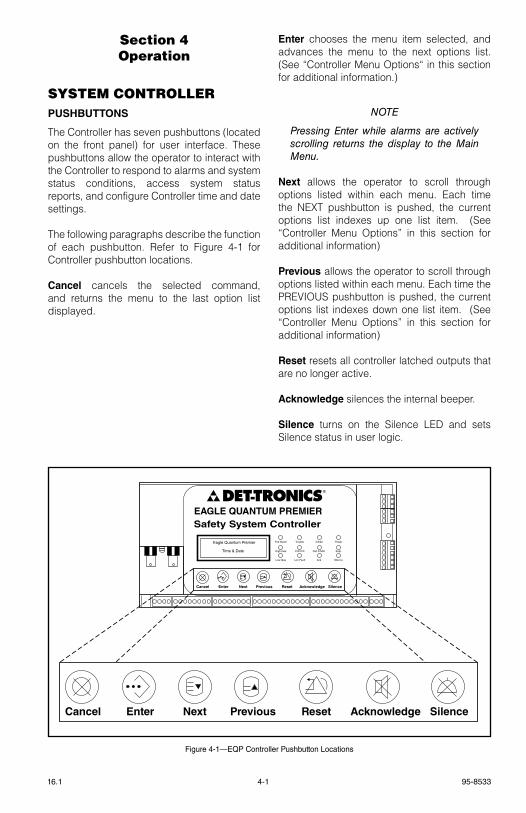
4-1 95-853316.1
Section 4operation
SySteM controllerPUSHBUTTONS
the Controller has seven pushbuttons (located on the front panel) for user interface. these pushbuttons allow the operator to interact with the Controller to respond to alarms and system status conditions, access system status reports, and configure Controller time and date settings.
the following paragraphs describe the function of each pushbutton. refer to Figure 4-1 for Controller pushbutton locations.
Cancel cancels the selected command, and returns the menu to the last option list displayed.
Enter chooses the menu item selected, and advances the menu to the next options list. (see “Controller Menu Options“ in this section for additional information.)
noTe
Pressing enter while alarms are actively scrolling returns the display to the Main Menu.
Next allows the operator to scroll through options listed within each menu. each time the NeXt pushbutton is pushed, the current options list indexes up one list item. (see “Controller Menu Options” in this section for additional information)
Previous allows the operator to scroll through options listed within each menu. each time the PrevIOUs pushbutton is pushed, the current options list indexes down one list item. (see “Controller Menu Options” in this section for additional information)
Reset resets all controller latched outputs that are no longer active.
Acknowledge silences the internal beeper.
Silence turns on the silence leD and sets silence status in user logic.
Cancel Enter Next Previous Reset Acknowledge Silence
EAGLE QUANTUM PREMIERSafety System Controller
Fire Alarm Inhibit Power
SuprHigh Gas
Trouble
Cntrl Flt
Lon FaultLow Gas Ack Silence
Out Inhibit
Eagle Quantum Premier
Time & Date
Cancel Enter Next Previous Reset Acknowledge Silence
DET-TRONICS®
Figure 4-1—EQP Controller Pushbutton Locations
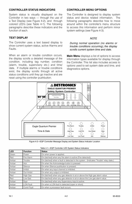
95-85334-216.1
CONTROLLER STATUS INDICATORS
system status is visually displayed on the Controller in two ways — through the use of a text Display (see Figure 4-2), and through colored leD’s (see table 4-1). the following paragraphs describe these indicators and the function of each.
TEXT DISPLAY
the Controller uses a text based display to show current system status, active Alarms and Faults.
When an alarm or trouble condition occurs, the display scrolls a detailed message of the condition, including tag number, condition (alarm, trouble, supervisory etc.) and time/date. If multiple alarms or trouble conditions exist, the display scrolls through all active status conditions until they go inactive and are reset using the controller pushbutton.
CONTROLLER MENU OPTIONS
the Controller is designed to display system status and device related information. the following paragraphs describe how to move around within the controller’s menu structure to access this information and perform minor system settings (see Figure 4-3).
noTe
During normal operation (no alarms or trouble conditions occurring), the display scrolls current system time and date.
Main Menu displays a list of options to access information types available for display through the Controller. this list also includes access to options used to set system date and time, and diagnostics options.
Fire Alarm Inhibit Power
SuprHigh Gas
Trouble
Cntrl Flt
Lon FaultLow Gas Ack Silence
Out Inhibit
Eagle Quantum Premier
Time & Date
EAGLE QUANTUM PREMIERSafety System Controller
Fire Alarm Inhibit Power
SuprHigh Gas
Trouble
Cntrl Flt
Lon FaultLow Gas Ack Silence
Out Inhibit
Eagle Quantum Premier
Time & Date
Cancel Enter Next Previous Reset Acknowledge Silence
DET-TRONICS®
Figure 4-2—EQP Controller Message Display and System Status Indicator Location
Table 4-1—EQP Controller LED System Status Indicators
LED Function Status
green Power On when power is applied.red Fire Alarm On (latched) when any fire alarm is active (Fire detected).Amber trouble On (latched) when a fault is detected in the system. (Indicates "trouble" relay state.)Amber Ack On when the Acknowledge button is pressed.Amber silence On when silence pushbutton is pressed.Amber Inhibit On when any input channel is inhibited.Amber Out Inhibit On when any output is inhibited.red High gas On (latched) when any gas detector is at or above the High gas alarm value.red low gas On (latched) when any gas detector is at or above the low gas alarm value.Amber supr On (latched) when any supervisory input is active.Amber lON Fault On when a lON fault is detected (open or short).Amber Contrl Fault On when a processor fault occurs.
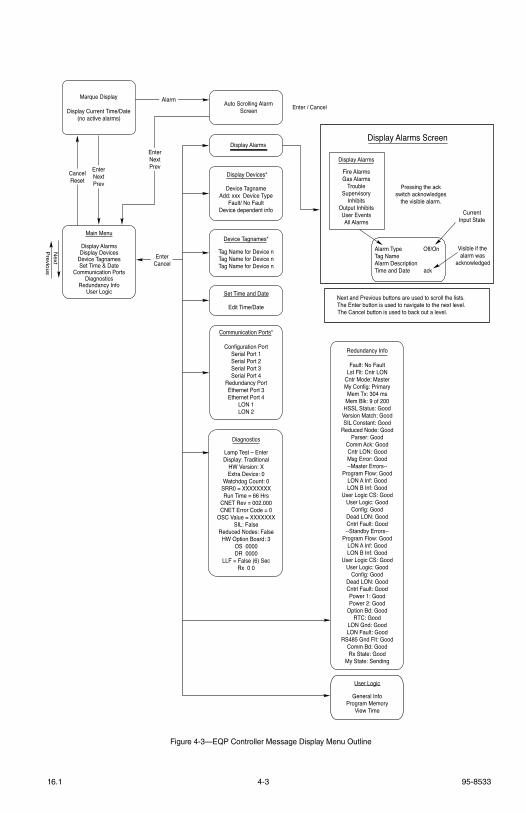
4-3 95-853316.1
Next and Previous buttons are used to scroll the lists.The Enter button is used to navigate to the next level.The Cancel button is used to back out a level.
Alarm Type Off/OnTag NameAlarm DescriptionTime and Date ack
Visible if thealarm was
acknowledged
Display Alarms Screen
CurrentInput State
Pressing the ackswitch acknowledges
the visible alarm.
Display Alarms
Enter / CancelAuto Scrolling AlarmScreen
Marque Display
Display Current Time/Date (no active alarms)
Communication Ports*
Configuration PortSerial Port 1Serial Port 2Serial Port 3Serial Port 4
Redundancy PortEthernet Port 3Ethernet Port 4
LON 1LON 2
Redundancy Info
Fault: No FaultLst Flt: Cntr LON
Cntr Mode: MasterMy Config: PrimaryMem Tx: 304 ms
Mem Blk: 9 of 200HSSL Status: Good
Version Match: GoodSIL Constant: Good
Reduced Node: GoodParser: Good
Comm Ack: GoodCntr LON: GoodMsg Error: Good--Master Errors--
Program Flow: GoodLON A Inf: GoodLON B Inf: Good
User Logic CS: GoodUser Logic: Good
Config: GoodDead LON: GoodCntrl Fault: Good--Standby Errors--
Program Flow: GoodLON A Inf: GoodLON B Inf: Good
User Logic CS: GoodUser Logic: Good
Config: GoodDead LON: GoodCntrl Fault: GoodPower 1: GoodPower 2: Good
Option Bd: GoodRTC: Good
LON Gnd: GoodLON Fault: Good
RS485 Gnd Flt: GoodComm Bd: GoodRx State: Good
My State: Sending
Main Menu
Display AlarmsDisplay Devices
Device TagnamesSet Time & Date
Communication PortsDiagnostics
Redundancy InfoUser Logic
Device TagnameAdd: xxx Device Type
Fault/ No FaultDevice dependent info
Display Devices*
Device Tagnames*
Tag Name for Device nTag Name for Device nTag Name for Device n
Set Time and Date
Edit Time/Date
Previous
Next
EnterNextPrev
CancelReset
EnterNextPrev
Alarm
EnterCancel
Diagnostics
Lamp Test – EnterDisplay: Traditional
HW Version: XExtra Device: 0
Watchdog Count: 0SRR0 = XXXXXXXXRun Time = 66 Hrs
CNET Rev = 002.000CNET Error Code = 0
OSC Value = XXXXXXXSIL: False
Reduced Nodes: FalseHW Option Board: 3
OS 0000DR 0000
LLF = False (6) SecRx 0 0
User Logic
General InfoProgram Memory
View Time
Display Alarms
Fire AlarmsGas Alarms
TroubleSupervisory
InhibitsOutput InhibitsUser EventsAll Alarms
Figure 4-3—EQP Controller Message Display Menu Outline
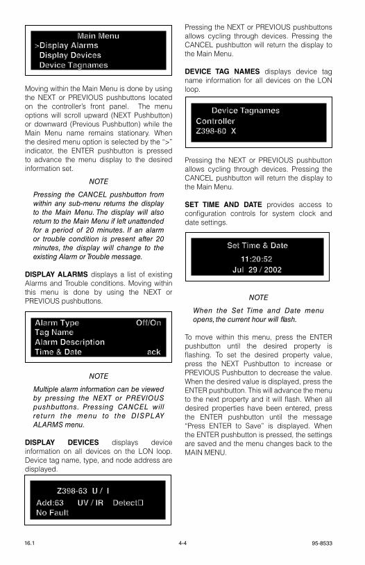
95-85334-416.1
Moving within the Main Menu is done by using the NeXt or PrevIOUs pushbuttons located on the controller’s front panel. the menu options will scroll upward (NeXt Pushbutton) or downward (Previous Pushbutton) while the Main Menu name remains stationary. When the desired menu option is selected by the “>” indicator, the eNter pushbutton is pressed to advance the menu display to the desired information set.
noTe
Pressing the CAnCeL pushbutton from within any sub-menu returns the display to the Main Menu. The display will also return to the Main Menu if left unattended for a period of 20 minutes. If an alarm or trouble condition is present after 20 minutes, the display will change to the existing Alarm or Trouble message.
DISPLAY ALARMS displays a list of existing Alarms and trouble conditions. Moving within this menu is done by using the NeXt or PrevIOUs pushbuttons.
noTe
Multiple alarm information can be viewed by pressing the neXT or PReVIoUS pushbuttons. Pressing CAnCeL will return the menu to the DISPLAY ALARMS menu.
DISPLAY DEVICES displays device information on all devices on the lON loop. Device tag name, type, and node address are displayed.
Pressing the NeXt or PrevIOUs pushbuttons allows cycling through devices. Pressing the CANCel pushbutton will return the display to the Main Menu.
DEVICE TAG NAMES displays device tag name information for all devices on the lON loop.
Pressing the NeXt or PrevIOUs pushbutton allows cycling through devices. Pressing the CANCel pushbutton will return the display to the Main Menu.
SET TIME AND DATE provides access to configuration controls for system clock and date settings.
noTe
When the Set Time and Date menu opens, the current hour will flash.
to move within this menu, press the eNter pushbutton until the desired property is flashing. to set the desired property value, press the NeXt Pushbutton to increase or PrevIOUs Pushbutton to decrease the value. When the desired value is displayed, press the eNter pushbutton. this will advance the menu to the next property and it will flash. When all desired properties have been entered, press the eNter pushbutton until the message “Press eNter to save” is displayed. When the eNter pushbutton is pressed, the settings are saved and the menu changes back to the MAIN MeNU.
>Display Alarms Display Devices Device Tagnames
Main Menu
Tag NameAlarm DescriptionTime & Date ack
Alarm Type Off/On
Add:63 UV / IR DetectNo Fault
Z398-63 U / I
11:20:52Set Time & Date
Jul 29 / 2002
ControllerZ398-80 X
Device Tagnames
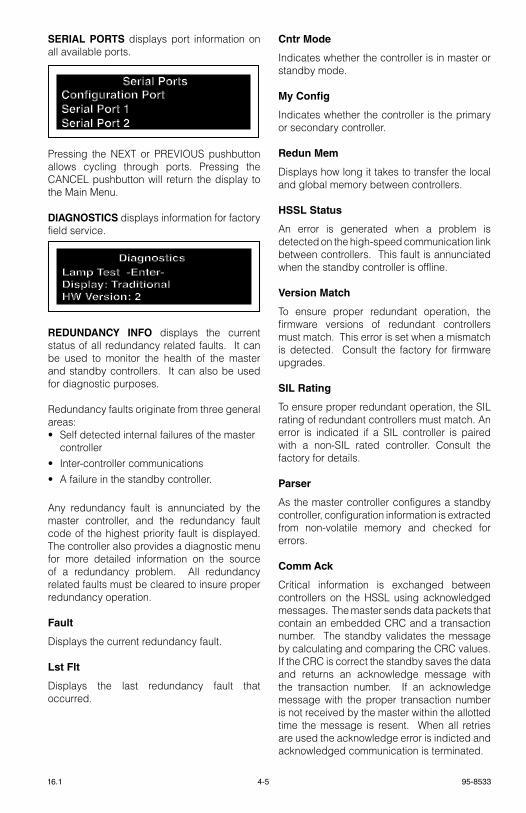
4-5 95-853316.1
SERIAL PORTS displays port information on all available ports.
Pressing the NeXt or PrevIOUs pushbutton allows cycling through ports. Pressing the CANCel pushbutton will return the display to the Main Menu.
DIAGNOSTICS displays information for factory field service.
REDUNDANCY INFO displays the current status of all redundancy related faults. It can be used to monitor the health of the master and standby controllers. It can also be used for diagnostic purposes.
redundancy faults originate from three general areas:• self detected internal failures of the master
controller• Inter-controller communications• A failure in the standby controller.
Any redundancy fault is annunciated by the master controller, and the redundancy fault code of the highest priority fault is displayed. the controller also provides a diagnostic menu for more detailed information on the source of a redundancy problem. All redundancy related faults must be cleared to insure proper redundancy operation.
Fault
Displays the current redundancy fault.
Lst Flt
Displays the last redundancy fault that occurred.
Cntr Mode
Indicates whether the controller is in master or standby mode.
My Config
Indicates whether the controller is the primary or secondary controller.
Redun Mem
Displays how long it takes to transfer the local and global memory between controllers.
HSSL Status
An error is generated when a problem is detected on the high-speed communication link between controllers. this fault is annunciated when the standby controller is offline.
Version Match
to ensure proper redundant operation, the firmware versions of redundant controllers must match. this error is set when a mismatch is detected. Consult the factory for firmware upgrades.
SIL Rating
to ensure proper redundant operation, the sIl rating of redundant controllers must match. An error is indicated if a sIl controller is paired with a non-sIl rated controller. Consult the factory for details.
Parser
As the master controller configures a standby controller, configuration information is extracted from non-volatile memory and checked for errors.
Comm Ack
Critical information is exchanged between controllers on the Hssl using acknowledged messages. the master sends data packets that contain an embedded CrC and a transaction number. the standby validates the message by calculating and comparing the CrC values. If the CrC is correct the standby saves the data and returns an acknowledge message with the transaction number. If an acknowledge message with the proper transaction number is not received by the master within the allotted time the message is resent. When all retries are used the acknowledge error is indicted and acknowledged communication is terminated.
Lamp Test -Enter-Display: TraditionalHW Version: 2
Diagnostics
Configuration PortSerial Port 1Serial Port 2
Serial Ports
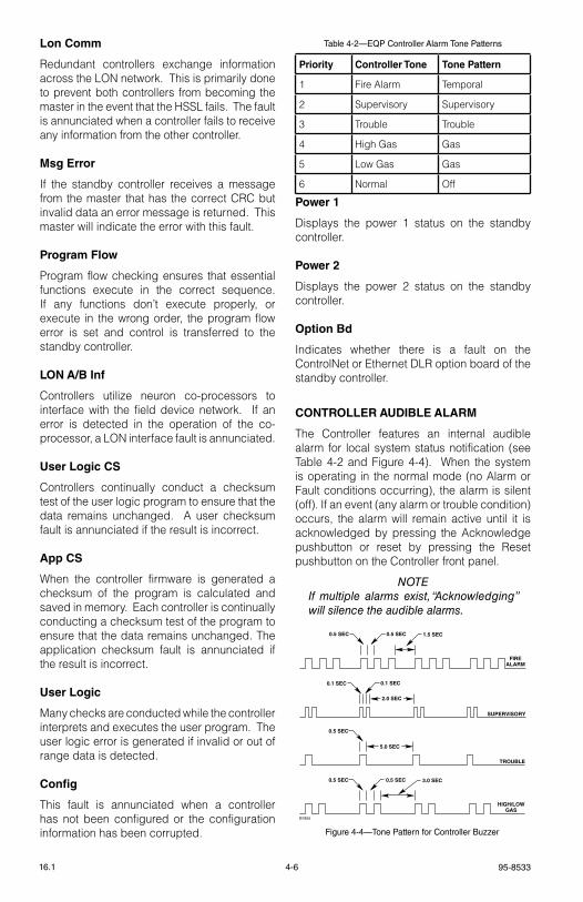
95-85334-616.1
Lon Comm
redundant controllers exchange information across the lON network. this is primarily done to prevent both controllers from becoming the master in the event that the Hssl fails. the fault is annunciated when a controller fails to receive any information from the other controller.
Msg Error
If the standby controller receives a message from the master that has the correct CrC but invalid data an error message is returned. this master will indicate the error with this fault.
Program Flow
Program flow checking ensures that essential functions execute in the correct sequence. If any functions don’t execute properly, or execute in the wrong order, the program flow error is set and control is transferred to the standby controller.
LON A/B Inf
Controllers utilize neuron co-processors to interface with the field device network. If an error is detected in the operation of the co-processor, a lON interface fault is annunciated.
User Logic CS
Controllers continually conduct a checksum test of the user logic program to ensure that the data remains unchanged. A user checksum fault is annunciated if the result is incorrect.
App CS
When the controller firmware is generated a checksum of the program is calculated and saved in memory. each controller is continually conducting a checksum test of the program to ensure that the data remains unchanged. the application checksum fault is annunciated if the result is incorrect.
User Logic
Many checks are conducted while the controller interprets and executes the user program. the user logic error is generated if invalid or out of range data is detected.
Config
this fault is annunciated when a controller has not been configured or the configuration information has been corrupted.
Power 1
Displays the power 1 status on the standby controller.
Power 2
Displays the power 2 status on the standby controller.
Option Bd
Indicates whether there is a fault on the ControlNet or ethernet Dlr option board of the standby controller.
CONTROLLER AUDIBLE ALARM
the Controller features an internal audible alarm for local system status notification (see table 4-2 and Figure 4-4). When the system is operating in the normal mode (no Alarm or Fault conditions occurring), the alarm is silent (off). If an event (any alarm or trouble condition) occurs, the alarm will remain active until it is acknowledged by pressing the Acknowledge pushbutton or reset by pressing the reset pushbutton on the Controller front panel.
noTeIf multiple alarms exist, “Acknowledging” will silence the audible alarms.
Table 4-2—EQP Controller Alarm Tone Patterns
Priority Controller Tone Tone Pattern
1 Fire Alarm temporal
2 supervisory supervisory
3 trouble trouble
4 High gas gas
5 low gas gas
6 Normal Off
0.5 SEC 0.5 SEC 1.5 SEC
FIREALARM
0.5 SEC 0.5 SEC 3.0 SEC
HIGH/LOWGAS
0.5 SEC
5.0 SEC
TROUBLE
0.1 SEC0.1 SEC
2.0 SEC
SUPERVISORY
B1855
Figure 4-4—Tone Pattern for Controller Buzzer
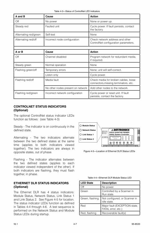
4-7 95-853316.1
CONTROLNET STATUS INDICATORS (Optional)
the optional ControlNet status indicator leDs function as follows: (see table 4-3)
steady - the indicator is on continuously in the defined state.
Alternating - the two indicators alternate between the two defined states at the same time (applies to both indicators viewed together). the two indicators are always in opposite states, out of phase.
Flashing - the indicator alternates between the two defined states (applies to each indicator viewed independent of the other). If both indicators are flashing, they must flash together, in phase.
ETHERNET DLR STATUS INDICATORS(Optional)
the ethernet Dlr has 4 status indicators: Module status, Network status, link status 1 and link status 2. see Figure 4-5 for location. the status indicator leDs function as defined in tables 4-4 through 4-6. A test sequence is performed on the Network status and Module status leDs during startup.
Table 4-3—Status of ControlNet LED Indicators
A and B Cause Action
Off No power None or power up.
steady red Faulted unit Cycle power. If fault persists, contact the factory.
Alternating red/green self-test None
Alternating red/off Incorrect node configuration Check network address and other ControlNet configuration parameters.
A or B Cause Action
Off Channel disabled Program network for redundant media, if required.
steady green Normal operation None
Flashing green/off temporary errors None; unit will self-correct.
listen only Cycle power.
Flashing red/off Media fault Check media for broken cables, loose connectors,missing terminators, etc.
No other nodes present on network Add other nodes to the network.
Flashing red/green Incorrect network configuration Cycle power or reset unit. If fault persists, contact the factory.
Figure 4-5—Location of Ethernet DLR Status LEDs
EAGLE QUANTUM PREMIERSafety System Controller
Fire Alarm Inhibit Power
SuprHigh Gas
Trouble
Cntrl Flt
Lon FaultLow Gas Ack Silence
Out Inhibit
Eagle Quantum Premier
Time & Date
Cancel Enter Next Previous Reset Acknowledge Silence
DET-TRONICS®
1 2
Module StatusNetwork StatusLink Status 1Link Status 2
Module Status
Network Status
Link Status 1
Link Status 2
LED State Description
Off No power.
green Controlled by a scanner in run state.
green, flashing Not configured, or scanner in idle state.
red Major fault (eXCePtION state, FAtAl error, etc.)
red, flashing recoverable fault(s)
Table 4-4—Ethernet DLR Module Status LED
95-85334-816.1
SEQUENCE OF EVENTS DURING A CONFIGURATION DATA DOWNLOADDuring a configuration download, the controller receives configuration data that is stored into flash memory. During the download process, the controller halts normal operation and resets a number of controller functions. Items affected and displayed during a configuration data download are listed in the following steps:
1. Halt the static logic and user logic programs.
2. Ignore field device lON communications. However, the controller continues to generate the lON heartbeat.
3. silence the Controller’s audible annunciator.
4. Initiate a trouble condition that is signaled by the amber trouble leD and relay.
5. Clear all Alarm and Fault events.
6. De-energize all 8 Controller relays.
7. Ignore Modbus communication.
8. ControlNet communication continues. ethernet Dlr communication goes through reset and configuration. Dlr communication remains offline during this sequence (approximately 30 seconds).
9. text display’s first line indicates "*** Program Mode ***"
10. text display’s third line displays download status.
a) "Config Download" indicates the serial transfer into memory from the PC to the Controller.
b) "erasing Flash" indicates that the controller is electronically erasing the contents of the Flash memory.
c) "Writing to Flash" indicates that configuration data stored in memory is being written down into Flash memory.
d) "Flash lock" indicates that the controller is locking the configuration data into the Flash memory.
CAUTION
The controller’s configuration data will be corrupted if power is removed during a download. Contact the factory if this occurs.
11. Initialize the rs-485 and configuration serial ports with new parameters.
12. Initialize the ControlNet or ethernet Dlr option board with new parameters.
13. enable static logic and user logic programs to operate. the first scan program is run first.
14. Accept field device lON communications.
15. Poll the device type variable from lON field devices.
16. Configure lON field devices.
17. Clear the trouble condition.
18. text display shows a normal operation marquee message.
a) text display’s first line indicates "Det-tronics eagle Quantum Premier".
b) text display’s third line displays time (24 hour format) and date (month/day/year).
noTe
Depending on the condition of the Lon devices, faults may persist for a number of minutes.
LED State Description
Off No link, no activity.
green link (100 Mbit/s) established.
green, flickering Activity (100 Mbit/s)
Yellow link (10 Mbit/s) established.
Yellow, flickering Activity (10 Mbit/s)
Table 4-6—Ethernet DLR Link Status 1 and Link Status 2 LEDs
LED State Description
Off No power or no IP address.
green Online, one or more connections established (CIP Class 1 or 3).
green, flashing Online, no connections established.
red Duplicate IP address, FAtAl error.
red, flashing One or More connections timed out (CIP Class 1 or 3).
Table 4-5—Ethernet DLR Network Status LED
4-9 95-853316.1
CONTROLLER REDUNDANCY
Pushbuttons
the pushbuttons are active on the master controller and inactive on the standby controller.
Controller Status Indicators
the status indicators are active on the master controller. All leDs except the power leD are off and the trouble relay is in the no trouble state.
Controller Relay Operation
the controller relays are fully functional on the master controller and the standby controller.
Text Display
the text display on the master controller is fully functional as explained in the previous section. the text display on the standby controller reads **standby Mode**, ready.
Controller Menu Options
the menu options are active on the master controller and inactive on the standby controller.
ControlNet or Ethernet DLR Status Indicators
the ControlNet or ethernet Dlr status indicators are active on the master and standby controller. see table 4-3 for status of ControlNet leD indicators and tables 4-4 through 4-6 for ethernet Dlr leD indicators.
Power-up Sequence
the power-up sequence for a redundant controller pair is as follows:
1. Make sure the lON and Hssl are connected correctly.
2. Apply power to both controllers.
3. Controllers go through their boot-up routine.
4. the controller that is connected with the primary end of the Hssl is identified as the primary controller and is assigned address 1.
5. the controller that is connected with the secondary end of the Hssl is assigned address 2.
6. If there are no faults present, the primary controller defaults to the master controller and the secondary controller defaults to the standby controller.
7. the master controller executes user logic and communicates with the connected lON devices.
8. the standby controller indicates that it is in standby mode and monitors the master controller.
9. the master and standby controller go through a synchronization process.
10. the power-up sequence is complete.
Synchronization
When a master controller detects a standby controller on the Hssl, it performs the following synchronization process:
1. Compare controller firmware versions and sIl rating. If they are not an exact match, the process stops and a fault is generated. Consult the factory for details.
2. standby controller indicates the synchronization steps.
3. Compare the user application programs. If there is a mis-match, the master will configure the standby controller via the Hssl.
4. Initiate the data synchronization process.
5. transfer the status of device inhibits and device removes.
6. transfer the complete alarm list, including alarm history.
7. transfer the real time clock (rtC) value.
8. Copy the local and global memory to the standby controller.
9. synchronization is complete and the standby controller indicates “ready”.
95-85334-1016.1
Sequence of Events During a Configuration Download
WARNING
The system is inactive and not executing logic/alarm functions during a program download (in both single and redundant controller configurations).
When downloading a new configuration to the master controller, the following sequence is executed:
1. the s³ software must be connected to the master controller.
2. Alter the configuration and execute the download command from s³.
3. the master controller goes into ‘Program’ mode and passes mastership to the standby controller.
4. the updated configuration file is loaded into the controller.
5. the controllers are automatically forced to switch over.
6. the master controller puts the standby controller into ‘Program’ mode and downloads the configuration.
7. the controller indicates “Device Download Active” until the lON devices have been successfully updated.
8. the configuration download is now complete.
Manual Switchover
the user can request a manual switchover from an externally wired switch. the request executes the following sequence:
1. verify that Hssl communication is good and there are no internal faults in the standby controller.
2. verify that the synchronization process is complete.
3. the master requests the standby to take control.
4. the standby takes control and becomes the master.
5. the controller indicates “Device Download Active” until the lON devices have been successfully updated.
Automatic Switchover
An automatic transfer will be initiated if the master controller goes into an error (self detected internal controller failure, program flow error in the controller, user logic checksum error or application checksum error). An automatic switchover executes the following sequence:
1. Check that the standby controller is online by verifying that Hssl communication is good and there are no internal faults in the standby controller.
2. verify that the synchronization process is complete.
3. the master requests the standby to take control.
4. the standby takes control and becomes the master.
Replacing a Faulty Controller
If the master controller fails and the standby controller is healthy, an automatic switchover will occur. to replace the failed controller, perform the following steps:
1. remove power. Disconnect plugs and remove the failed controller.
2. Mount the new controller.
3. Connect the lON to the new controller.
4. Connect the Hssl.
5. Connect any other I/O used.
6. Apply power to the controller.
7. A controller synchronization occurs and the new controller is configured and indicates “ready” as the standby controller.
8. If preferred, perform a manual switchover to return the primary controller to the master status.
4-11 95-853316.1
enHAnceD DIScrete I/o MoDUlethe eDIO Module (see Figure 4-6) has 18 leD status indicators, two for the device and two for each channel, located on the front panel. refer to tables 4-7 and 4-8 for a description of the leD indicators.
POWER-UP SEQUENCE
set the module address switch prior to applying power.
eDIO module power-up sequence illuminates the leDs for the device and all of its channels. First the power and fault leDs are illuminated, indicating that the device is in a power-up mode. Next the leDs are illuminated in the following sequences:
• sequentially each channel active red leD is illuminated, starting with channel 1 and continuing through channel 8.
• When the red leD for channel 8 is illuminated, sequentially each channel active red leD is turned off, starting with channel 1 and continuing through channel 8.
• Next, the channel fault amber leDs are tested in the same manner as the channel active red leDs.
When all the leDs have been illuminated, the eDIO module displays the device’s lON address by illuminating the channel active red leD. lON dip switches 1 though 8 will be displayed on channels 1 through 8. When a dip switch is set to the ON position, the channel active red leD will be illuminated. the address is displayed for two seconds.
Once the address has been displayed, the device’s fault leD will turn off.
After the power-up sequence, the device will either display an unconfigured state or normal operation state. In the unconfigured state, the channel fault amber leDs flash ON and OFF at the same rate for all channels.
STATUS INDICATOR LEDs
Figure 4-6—EDIO Module Status Indicator Location
Table 4-7—EDIO Module - Device Status Indicators
Table 4-8—EDIO Module - Channel Status Indicators
LED Device Status
green On when power is present.
Amber When On steady indicates device is disabled or must be replaced. Possible Watchdog timer problem.
noTeBlinks one time at power-up.
LED Channel Status
red When On steady indicates the input circuit is closed or the output circuit is active
Amber When Blinking indicates a low power condition is present or channel is not properly configured. steady indicates a channel fault.
95-85334-1216.1
8 cHAnnel DcIo MoDUlethe DCIO Module (see Figure 4-7) has 18 leD status indicators, two for the device and two for each channel, located on the front panel. refer to tables 4-9 and 4-10 for a description of the leD indicators.
POWER-UP SEQUENCE
set the module address switch prior to applying power.
DCIO module power-up sequence illuminates the leDs for the device and all of its channels. First the power and fault leDs are illuminated, indicating that the device is in a power-up mode. Next the leDs are illuminated in the following sequences:
• sequentially each channel active red leD is illuminated, starting with channel 1 and continuing through channel 8.
• When the red leD for channel 8 is illuminated, sequentially each channel active red leD is turned off, starting with channel 1 and continuing through channel 8.
• Next, the channel fault amber leDs are tested in the same manner as the channel active red leDs.
When all the leDs have been illuminated, the DCIO module displays the device’s lON address by illuminating the channel active red leD. lON dip switches 1 though 8 will be displayed on channels 1 through 8. When a dip switch is set to the ON position, the channel active red leD will be illuminated. the address is displayed for two seconds.
Once the address has been displayed, the device’s fault leD will turn off.
After the power-up sequence, the device will either display an unconfigured state or normal operation state. In the unconfigured state, the channel fault amber leDs flash ON and OFF at the same rate for all channels.
Table 4-9—DCIO Module - Device Status Indicators
Table 4-10—DCIO Module - Channel Status Indicators
STATUS INDICATOR LEDs
LED Device Status
green On when power is present.
Amber When On steady indicates device is disabled or must be replaced. Possible Watchdog timer problem.
noTeBlinks one time at power-up.
LED Channel Status
red When On steady indicates the input circuit is closed or the output circuit is active
Amber When Blinking indicates a low power condition is present or channel is not properly configured. steady indicates a channel fault.
Figure 4-7—DCIO Module Status Indicator Location
4-13 95-853316.1
8 cHAnnel relAy MoDUlethe relay Module (see Figure 4-8) has 18 leD status indicators, two for the device and two for each channel, located on the front panel. refer to tables 4-11 and 4-12 for a description of the leD indicators.
POWER-UP SEQUENCE
set the module address switch prior to applying power.
relay module power-up sequence illuminates the leDs for the device and all of its channels. First the power and fault leDs are illuminated, indicating that the device is in a power-up mode. Next the leDs are illuminated in the following sequences:
• sequentially each channel active red leD is illuminated, starting with channel 1 and continuing through channel 8.
• When the red leD for channel 8 is illuminated, sequentially each channel active red leD is turned off, starting with channel 1 and continuing through channel 8.
• Next, the channel fault amber leDs are tested in the same manner as the channel active red leDs.
When all the leDs have been illuminated, the relay module displays the device’s lON address by illuminating the channel active red leD. lON dip switches 1 through 8 will be displayed on channels 1 through 8. When a dip switch is set to the ON position, the channel active red leD will be illuminated. the address is displayed for two seconds.
Once the address has been displayed, the device’s fault leD will turn off.
After the power-up sequence, the device will either display an unconfigured state or normal operation state. In the unconfigured state, the channel fault amber leDs flash ON and OFF at the same rate for all channels.
Table 4-11—Relay Module - Device Status Indicators
Table 4-12—Relay Module - Channel Status Indicators
LED Device Status
green On when power is present.
Amber When On steady indicates device is disabled or must be replaced. Possible Watchdog timer problem.
noTeBlinks one time at power-up.
LED Channel Status
red When On steady indicates the input circuit is active
Amber When Blinking indicates a low power condition is present or channel is not properly configured.
Figure 4-8—Relay Module Status Indicator Location
STATUS INDICATOR LEDs
95-85334-1416.1
AnAlog InpUt MoDUlethe Analog Input Module (see Figure 4-9) has 18 leD status indicators, two for the device and two for each channel, located on the front panel. refer to tables 4-13 and 4-14 for a description of the leD indicators.
POWER-UP SEQUENCE
set the module address switch prior to applying power.
the Analog Input Module power-up sequence illuminates the leDs for the device and all of its channels. First the power and fault leDs are illuminated, indicating that the device is in a power-up mode. Next the leDs are illuminated in the following sequences:
• sequentially each channel active red leD is illuminated, starting with channel 1 and continuing through channel 8.
• When the red leD for channel 8 is illuminated, sequentially each channel active red leD is turned off, starting with channel 1 and continuing through channel 8.
• Next, the channel fault amber leDs are tested in the same manner as the channel active red leDs.
When all the leDs have been illuminated, the analog input module displays the device’s lON address by illuminating the channel active red leD. lON dip switches 1 through 8 will be displayed on channels 1 through 8. When a dip switch is set to the ON position, the channel active red leD will be illuminated. the address is displayed for two seconds.
Once the address has been displayed, the device’s fault leD will turn off.
After the power-up sequence, the device will either display an unconfigured state or normal operation state. In the unconfigured state, the channel fault amber leDs flash ON and OFF at the same rate for all channels.
Table 4-13—Analog Input Module - Device Status Indicators
Table 4-14— Analog Input Module - Channel Status Indicators
LED Device Status
green On when power is present.
Amber When On steady indicates device is disabled or must be replaced. Possible Watchdog timer problem.
noTeBlinks one time at power-up.
LED Channel Status
red When Blinking indicates a low alarm. When On steady indicates a high alarm.
Amber When Blinking indicates a low power condition is present or channel is not properly configured. On steady indicates out of range condition
Figure 4-9—Analog Input Module Status Indicator Location
STATUS INDICATOR LEDs

4-15 95-853316.1
eQ21XXpSM poWer SUpply MonItorthe power supply monitor (see Figure 4-10) has three leDs used to provide a visual indication of device status:
eQ2220gFM groUnD FAUlt MonItorthe ground fault monitor (see Figure 4-11) has three leDs used to provide a visual indication of device status:
noTe
The Ground Fault Monitor LeD will respond immediately to a ground fault condition. The relay contact requires the condition to exist for 10 seconds before it activates.
LED Device Status
green When On indicates power is supplied to device
red When Flashing indicates an alarm or fault condition is present.
Amber When On indicates device is disabled. Module must be replaced.
LED Device Status
+ gND Flt leD Indicates Amber in the presence of a "+" ground fault.
- gND Flt leD Indicates Amber in the presence of a "-" ground fault.
POWer leD Indicates green when the unit is powered.
+ +
+
++
+
+
+
+
+
+
+
+
+
++
AMBER LED
RED LEDGREEN LED
1
1
1
1
Figure 4-10—EQ21xxPSM Status Indicator Location
Table 4-15—Power Supply Monitor Status Indicators
Table 4-16—Ground Fault Monitor Status Indicators
+ GND FLT LED
– GND FLT LED
PWR LED
A2243
Figure 4-11—Ground Fault Monitor Status Indicator Location
95-85334-1616.1
eQ22XXIDc SerIeS InItIAtIng DeVIce cIrcUIt (IDc)the IDC has three leDs (located at the center of the IDC communication module circuit board) to provide a visual indication of device status.
noTe
The Initiating Device Circuit Ground Fault Monitor responds to the presence of a ground fault within the power circuitry. It provides a supervised dry contact input and ground fault monitoring circuitry for indicating a power supply trouble condition.
noTe
A blinking red LeD on an IDCSC indicates trouble such as a wiring fault (open or short circuit) or not configured.
eQ22XXDcU AnD eQ22XXDcUeX DIgItAl coMMUnIcAtIon UnItSthe DCUs have three leDs to provide a visual indication of device status. they are visible through the window on the enclosure cover.
noTe
If the communication module has not been configured, the red LeD blinks at a 4 Hz rate.
noTe
The amber LeD is provided for factory diagnostic purposes and is not used in the system. Illumination of the amber LeD normally indicates a failure in the communication chip. Replacement of the communication module circuit board is required.
Table 4-17—Initiating Device Circuit Status Indicators Table 4-18—DCU Status Indicators
LED Device Status
green When On indicates device has power
red When On indicates an Alarm or Fault condition is present.On steady = One of the inputs is
active.Blinking = Fault condition
such as an open input circuit or not configured.
Amber When On indicates a device is disabled. Module must be replaced.
Device Status
LED Status
Power-up Pulsed at a rate of 0.5 Hz
Calibration Pulsed at a rate of 1 HZ or on steady
Fault Pulsed at a rate of 4 Hz
Alarm On steady
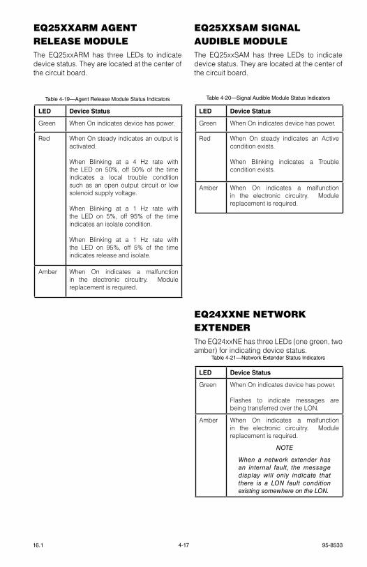
4-17 95-853316.1
eQ25XXArM Agent releASe MoDUlethe eQ25xxArM has three leDs to indicate device status. they are located at the center of the circuit board.
eQ25XXSAM SIgnAl AUDIBle MoDUlethe eQ25xxsAM has three leDs to indicate device status. they are located at the center of the circuit board.
eQ24XXne netWorK eXtenDerthe eQ24xxNe has three leDs (one green, two amber) for indicating device status.
LED Device Status
green When On indicates device has power.
red When On steady indicates an output is activated.
When Blinking at a 4 Hz rate with the leD on 50%, off 50% of the time indicates a local trouble condition such as an open output circuit or low solenoid supply voltage.
When Blinking at a 1 Hz rate with the leD on 5%, off 95% of the time indicates an isolate condition.
When Blinking at a 1 Hz rate with the leD on 95%, off 5% of the time indicates release and isolate.
Amber When On indicates a malfunction in the electronic circuitry. Module replacement is required.
LED Device Status
green When On indicates device has power.
red When On steady indicates an Active condition exists.
When Blinking indicates a trouble condition exists.
Amber When On indicates a malfunction in the electronic circuitry. Module replacement is required.
LED Device Status
green When On indicates device has power.
Flashes to indicate messages are being transferred over the lON.
Amber When On indicates a malfunction in the electronic circuitry. Module replacement is required.
noTe
When a network extender has an internal fault, the message display will only indicate that there is a Lon fault condition existing somewhere on the Lon.
Table 4-19—Agent Release Module Status Indicators
Table 4-21—Network Extender Status Indicators
Table 4-20—Signal Audible Module Status Indicators
95-85334-1816.1
SySteM StArtUpPRE-OPERATION CHECKS
General
Insulate all shields to prevent shorts to device housing or to any other conductor.
Place alarm/release output in “Bypass/Isolate” when servicing devices.
Maintain a log book containing the type and serial numbers of devices as well as the location and date of installation.
Maintain a log of maintenance activities.
Observe normal precautions for handling electrostatic sensitive devices.
LON
rocker switches for each lON device must be set to the desired address prior to power-up.
test the loop with no power applied. DC resistance should be equal on A and B.
Check polarity on A and B (no rolls). COM 1 connects to COM 2; COM 2 connects to COM 1. A connects to A and B to B.
Measure voltage. A to chassis ground measures approximately +7.5 vdc. B to ground measures approximately –7.5 vdc.
Measure signal (400 mv P-P min.). (Use oscilloscope if possible).
Check fault tolerance by introducing a short.
Controller
the I/O and lON wiring is correctly installed, observing polarity. All cable shields are properly terminated and insulated.
Power wiring is installed and power source is operational.
Chassis ground stud must be connected to earth ground.
Redundant Controller
the I/O and lON wiring is correctly installed, observing polarity. All cable shields are properly terminated and insulated.
Power wiring is installed and power source is operational.
Chassis ground stud must be connected to earth ground.
the Hssl cable is connected between the two controllers.
EDIO/DCIO Module
verify correct address setting.
Check signal circuits for correct polarity.
Check for correct installation of eOl resistors.
Relay Module
verify correct address setting.
Check for correct output connections.
Analog Input Module
verify correct address setting.
Check for correct input connections.
Check each channel with a loop current input.
Power Supplies and Power Monitors
verify all earth ground connections as specified in the wiring instructions.
verify correct ac power to supply.
Check power distribution to ensure that all devices are receiving power.
Check power trouble indicator by introducing an open to the battery.
4-19 95-853316.1
Ground Fault Monitor
verify earth ground connections as specified in the wiring instructions.
Check power distribution to ensure that all devices are receiving power.
DCUs
verify correct address setting.
Check modules for correct orientation.
Check for the presence of contaminants or poisoning agents.
Device should be oriented with the sensor pointing down.
IDCs
verify correct address setting.
Check for correct installation of eOl resistors.
ARMs
verify correct address setting.
Check jumpers.
SAMs
verify correct address setting.
Check signal circuits for correct polarity.
Check for correct installation of eOl resistors.
Check jumpers.
GENERAL START-UP PROCEDURES
1. Output loads that are controlled by the system should be secured (remove power from all output devices) to prevent actuation.
2. Check all system wiring for proper connection.
3. Inspect all devices to verify that they have not been physically damaged in shipment.
4. Apply power to the system.
noTe
To prevent the network modules from going into a fault isolation condition, apply power to the eQP Controller prior to applying power to the network devices.
5. Program the system for the desired operation using Det-tronics safety system software (s³). Download configuration data to all devices.
noTe
After system configuration has been completed, the entire system should be tested for proper operation to ensure that configuration was performed properly.
6. Calibrate the sensors.
7. ensure that all trouble and alarm conditions have been cleared and the eQP Controller is reset, then remove mechanical blocking devices (if used) and restore power to the output loads.

95-85334-2016.1
START-UP PROCEDURE FOR CONTROLLER
the Controller is powered-up when the Power supply is turned on. When the Power supply has been powered-up, verify power at the Controller by verifying that the green leD indicator is on. this indicator is located on the front of the Controller.
to verify that the Controller is powered-up and operating properly, ensure that:
1. When power is first applied, all leDs are on. the ACk leD flashes while the memory test is running. When initialization is complete, only the green power leD remains lit.
2. the ethernet/serial communication indicators continuously flash (if active).
noTe
For the ethernet Interface Board, the blue LeDs associated with ports 3 and 4 will remain on when the ports are ready for communication. Flashing green and amber LeDs indicate active transmit and receive. The amber indicator on the front of the RJ45 connector indicates a 10 Mb/s link is established. The green indicator on the front of the RJ45 connector indicates a 100 Mb/s link is established.
3. the text display runs an initialization routine. When initialization is complete and if all alarms and trouble conditions are cleared, the text display shows the current time and date. If the controller has been unpowered for more than 12 hours, the time and date may have to be set. If an alarm or trouble condition exists, it will be displayed until the condition is corrected and the reset button is pressed. If the controller has not been software configured, unconfigured devices will be displayed. Configuration must be done using s³ safety system software before proceeding.
4. the leDs on the front panel provide an indication of the system status.
5. ensure configuration was performed properly.
6. After any modifications have been made either to the installation or to configuration software, always check the entire system for proper operation in order to ensure that the changes were performed properly.
STARTUP PROCEDURE FOR EDIO MODULE
Configuration
the eDIO Module is an eight-channel device. each channel is capable of being configured as an input or output, independent of any other channel.
noTe
The module is configured using Det-Tronics Safety System Software.
Activation Time
timers are made available for output circuits only. timers are used primarily to set the timing of output release in a suppression system. timers provide a pulse timed output for the time period specified in the configuration of the channel. the channel output goes active when commanded by the system logic and remains on until the timer expires.
Static Logic Mode
each input channel can be configured as a Fire Alarm, trouble, low gas Alarm, High gas Alarm, supervisory, or Other type of channel, independent of any other channel configuration. the type selected determines the logic the system uses to configure Indicators, Alarms and Messages.
For example: When an input is selected as Fire type, the Fire leD on the Controller and Audible alarm will automatically actuate when that input channel is active.
4-21 95-853316.1
EDIO Startup
1. the Power-on leD should be illuminated. the Fault leD should blink once on power up, then remain off.
2. the input circuits should indicate the proper state of the input device (channel active leD illuminates when the circuit is closed). Check the input power supply and associated wiring. verify proper voltage per the troubleshooting matrix.
3. the output circuits should indicate the proper state for the programmed device (channel active leD illuminates when the circuit is active). Check the power supply and associated wiring. verify proper voltage per the troubleshooting matrix.
4. the circuits should not indicate a fault condition (channel fault leD illuminates when the circuit is in fault). Check the end-of-line devices and associated wiring. verify proper voltage per the troubleshooting matrix.
5. test the entire system for proper operation to ensure that the configuration was performed properly.
STARTUP PROCEDURE FOR DCIO MODULE
Configuration
the DCIO Module is an eight-channel device. each channel is capable of being configured as an input or output, independent of any other channel.
noTe
The module is configured using Det-Tronics Safety System Software.
Activation Time
timers are made available for output circuits only. timers are used primarily to set the timing of output release in a suppression system. timers provide a pulse timed output for the time period specified in the configuration of the channel. the channel output goes active when commanded by the system logic and remains on until the timer expires.
Static Logic Mode
each input channel can be configured as a Fire Alarm, trouble, low gas Alarm, High gas Alarm, supervisory, or Other type of channel, independent of any other channel configuration. the type selected determines the logic the system uses to configure Indicators, Alarms and Messages.
For example: When an input is selected as Fire type, the Fire leD on the Controller and Audible alarm will automatically actuate when that input channel is active.
95-85334-2216.1
DCIO Startup
1. the Power-on leD should be illuminated. the Fault leD should blink once on power up, then remain off.
2. the input circuits should indicate the proper state of the input device (channel active leD illuminates when the circuit is closed). Check the input power supply and associated wiring. verify proper voltage per the troubleshooting matrix.
3. the output circuits should indicate the proper state for the programmed device (channel active leD illuminates when the circuit is active). Check the power supply and associated wiring. verify proper voltage per the troubleshooting matrix.
4. the circuits should not indicate a fault condition (channel fault leD illuminates when the circuit is in fault). Check the end-of-line devices and associated wiring. verify proper voltage per the troubleshooting matrix.
5. test the entire system for proper operation to ensure that the configuration was performed properly.
Relay Module Startup
1. the Power-on leD should be illuminated. the Fault leD should blink once on power up, then remain off.
2. the output circuits should indicate the proper state for the programmed device (channel active leD illuminates when the circuit is active).
3. test the entire system for proper operation to ensure that the configuration was performed properly.
Analog Input Module Startup
1. the Power-on leD should be illuminated. the Fault leD should blink once on power up, then remain off.
2. the input circuits should indicate the proper state for the programmed device (channel active leD illuminates when the circuit is active).
3. the circuits should not indicate a fault condition (channel fault leD illuminates when the circuit is in fault).
4. test the entire system for proper operation to ensure that the configuration was performed properly.

5-1 95-853316.1
Section 5Maintenance
noTe
Refer to the eagle Quantum Premier Sys tem Safe t y Manua l (number 95-8599) for specific requirements and recommendations applicable to the proper installation, operation, and maintenance of all SIL-Certified eQP systems.
roUtIne MAIntenAnceto ensure reliable protection, it is important to check and calibrate the system on a regularly scheduled basis. the frequency of checks is determined by the requirements of the particular installation.
BATTERIES
Batteries must be replaced every 48 months, or sooner if required by local codes.
IMPORTANT!
only sealed batteries are to be used.
MANUAL CHECK OF OUTPUT DEVICES
It is important that response devices be checked initially when the system is installed, as well as periodically during an on-going maintenance program.
CAUTION!
Be sure to secure all output devices that are actuated by the system to prevent unwanted activation of equipment, and remember to place these output devices back into service when the checkout is complete.
O-RING MAINTENANCE
WARNING!
Th e h a z a rd o u s a re a m u s t b e de-classified prior to removing a junction box cover with power applied.
A rubber O-ring is used to ensure that the junction box cover will seal tightly and provide protection against water entry. the enclosure
should be opened periodically, and the O-ring inspected for breaks, cracks and dryness.
to test O-ring: remove it from the enclosure and stretch it slightly. If cracks are visible, replace it. If it feels dry, a thin coating of lubricant should be applied. When re-installing the O-ring, be sure that it is properly seated in the housing groove. It is imperative that this O-ring be properly installed and in good condition. Failure to properly maintain it can allow water to enter the enclosure and cause premature failure. A coating of lubricant should also be applied to the threads on the cover before re-assembling the enclosure. this will both lubricate the cover threads and help prevent moisture from entering the enclosure.
CAUTION!
The o-rings should be lubricated with a silicone free grease. The use of other lubricants is not recommended, since they can adversely affect the performance of some sensors. Under no circumstances should a lubricant or compound containing silicone be used on systems using catalytic type combustible gas sensors.
gAS SenSor MAIntenAnceAll gas sensors must be calibrated on a regular basis. Calibration should typically be performed every 90 days for catalytic and electrochemical sensors.
Catalytic sensors have a finite lifespan. If a successful calibration cannot be performed, replace the sensor and recalibrate following the procedure described in the “Calibration” section below. Always compare part numbers to be sure that the correct replacement sensor is being used.
CAUTION!
exposure of the sensor to h igh concentrations of combustible gases for extended periods of t ime can introduce stress to the sensing element and seriously affect its performance. After exposure, recalibration should immediately be performed, and the sensor should be replaced if necessary.
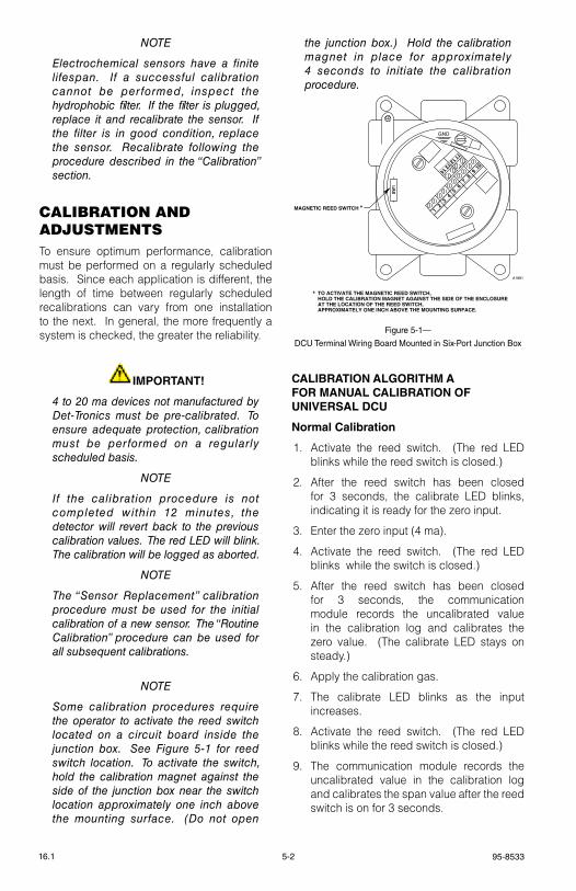
95-85335-216.1
noTe
electrochemical sensors have a finite lifespan. If a successful calibration cannot be performed, inspect the hydrophobic filter. If the filter is plugged, replace it and recalibrate the sensor. If the filter is in good condition, replace the sensor. Recalibrate following the procedure described in the “Calibration” section.
cAlIBrAtIon AnD ADJUStMentSto ensure optimum performance, calibration must be performed on a regularly scheduled basis. since each application is different, the length of time between regularly scheduled recalibrations can vary from one installation to the next. In general, the more frequently a system is checked, the greater the reliability.
IMPORTANT!
4 to 20 ma devices not manufactured by Det-Tronics must be pre-calibrated. To ensure adequate protection, calibration must be performed on a regularly scheduled basis.
noTe
If the calibration procedure is not completed within 12 minutes, the detector will revert back to the previous calibration values. The red LeD will blink. The calibration will be logged as aborted.
noTe
The “Sensor Replacement” calibration procedure must be used for the initial calibration of a new sensor. The “Routine Calibration” procedure can be used for all subsequent calibrations.
noTe
Some calibration procedures require the operator to activate the reed switch located on a circuit board inside the junction box. See Figure 5-1 for reed switch location. To activate the switch, hold the calibration magnet against the side of the junction box near the switch location approximately one inch above the mounting surface. (Do not open
the junction box.) Hold the calibration magnet in place for approximately 4 seconds to initiate the calibration procedure.
CALIBRATION ALGORITHM A FOR MANUAL CALIBRATION OF UNIVERSAL DCU
Normal Calibration
1. Activate the reed switch. (the red leD blinks while the reed switch is closed.)
2. After the reed switch has been closed for 3 seconds, the calibrate leD blinks, indicating it is ready for the zero input.
3. enter the zero input (4 ma).
4. Activate the reed switch. (the red leD blinks while the switch is closed.)
5. After the reed switch has been closed for 3 seconds, the communication module records the uncalibrated value in the calibration log and calibrates the zero value. (the calibrate leD stays on steady.)
6. Apply the calibration gas.
7. the calibrate leD blinks as the input increases.
8. Activate the reed switch. (the red leD blinks while the reed switch is closed.)
9. the communication module records the uncalibrated value in the calibration log and calibrates the span value after the reed switch is on for 3 seconds.
GND
910
78
56
34
12
1314
1112
A1881
MAGNETIC REED SWITCH *
* TO ACTIVATE THE MAGNETIC REED SWITCH,HOLD THE CALIBRATION MAGNET AGAINST THE SIDE OF THE ENCLOSUREAT THE LOCATION OF THE REED SWITCH,APPROXIMATELY ONE INCH ABOVE THE MOUNTING SURFACE.
SW1
Figure 5-1—
DCU Terminal Wiring Board Mounted in Six-Port Junction Box
5-3 95-853316.1
10. the calibrate leD stays on steady.
11. remove the span gas, and return the analog input to normal.
12. Activate the reed switch. (the red leD blinks for 3 seconds while the reed switch is closed)
13. the calibration is complete. the calibrate leD turns off.
noTe
If the calibration is not completed within 12 minutes, the previous calibration values are restored and the calibration is logged as aborted. The calibrate LeD will flash.
Sensor Replacement
WARNING!
Th e h a z a rd o u s a re a m u s t b e de-classified prior to removing a junction box cover with power applied.
1. Open the junction box cover and press the sensor replacement switch.
2. the calibrate leD on the communication module will flash, indicating it is ready for the zero input.
3. replace the sensor and apply the zero input (4 ma).
4. Activate the reed switch. (the red leD flashes for 3 seconds while the switch is closed.)
5. the communication module records the uncalibrated value in position one of the calibration log and calibrates the zero value. (the calibrate leD stays on steady.)
6. Apply the calibration gas.
7. the calibrate leD flashes when the input increases.
8. Activate the reed switch. (the red leD flashes for 3 seconds while the reed switch is closed.)
9. the communication module records the uncalibrated value in the first register of the calibration log and calibrates the span value.
10. the calibrate leD stays on steady.
11. remove the span gas and return the analog input to normal.
12. Activate the reed switch. (the red leD flashes for 3 seconds while the switch is closed.)
13. the calibration is complete. (the calibrate leD turns off.)
noTe
Pressing the Sensor Replacement Switch aborts calibration and starts over.
noTe
Resetting the communication module will abort the sensor replacement.
CALIBRATION ALGORITHM C FOR COMBUSTIBLE GAS DCUS AND AUTOMATIC CALIBRATION OF UNIVERSAL DCUs
CAUTION!
After exposing the H2S sensor to high concentrations of gas, it should be exposed to fresh air for at least 30 minutes, and re-calibrated.
Routine Calibration
1. Apply the zero gas.
2. Activate the reed switch for at least 4 seconds. (the red leD flashes for 3 seconds while the switch is activated.)
3. the calibrate leD on the communication module flashes, indicating it is ready for the zero input.
4. Wait until the calibrate leD stays on steady (approximately 4 seconds).
noTe
The communication module records the uncalibrated value in the calibration log and calibrates the zero value during this time.
5. Apply the calibration gas. (the calibrate leD flashes when the sensor detects gas.)
6. When the sensor input has been stable for 30 seconds, the communication module records the uncalibrated value in the calibration log, and calibrates the span value.

95-85335-416.1
7. the calibrate leD stays on steady.
8. remove the calibration gas.
9. the communication module waits until the sensor input drops below 4% full scale.
10. the calibration is complete. (the calibrate leD turns off.)
noTe
If the calibration procedure is not completed within 12 minutes, calibration will be aborted and the detector will revert back to the previous calibration values. The red LeD will flash and the calibration will be logged as aborted.
Initial Installation and Sensor Replacement — Combustible Gas (CGS Sensor)
noTe
When replacing a sensor, compare part numbers to be sure that the correct replacement sensor is used.
WARNING!
Th e h a z a rd o u s a re a m u s t b e de-classified prior to removing a junction box cover with power applied.
1. remove the cover from the DCUeX enclosure.
2. Press the sensor replacement switch on the communication module for approxImately 1 second. (the calibrate leD on the communication module flashes, indicating that it is ready for the zero input.)
noTe
Pressing the sensor replacement switch prevents the communication module from generating a fault signal when the input drops to zero due to sensor removal. The calibration will not be aborted if the calibration procedure is not completed within 12 minutes.
3. Move the Calibration switch to the “calibrate” position.
4. replace the sensor.
5. Connect a volt meter to the test points on the transmitter board. Connect the “+” lead to tP1 (red). Connect the “–” lead to tP2 (black).
6. Wait at least 5 minutes for the sensor output to stabilize, then adjust r2 for a reading of 0.40 vdc (4 ma) on the meter.
noTe
Do not make adjustments to R1 when calibrating the sensor.
7. Move the Calibrate switch to the “normal” position.
8. Activate the reed switch for 4 seconds. (the red leD flashes for 3 seconds while the switch is activated.) the communication module records the uncalibrated value in position one of the calibration log and calibrates the zero value. the calibrate leD goes on steady.
9. Move the Calibration switch to the “calibrate” position.
10. Apply the calibration gas and wait for the output to stabilize.
11. With 50% lFl calibration gas applied to sensor, adjust r3 for a reading of 1.2 vdc (12 ma) on the volt meter.
12. Move the Calibrate switch to the “normal” position. (the red leD flashes.)
13. Activate the reed switch. the red leD flashes for 3 seconds while the switch is activated.
14. the communication module records the uncalibrated value in the first register of the calibration log and calibrates the span value. the calibrate leD stays on steady.
15. remove the calibration gas and replace the DCU enclosure cover.
16. the communication module waits until the analog value drops below 4% full scale. the calibration is complete. (the calibrate leD turns off.)
noTe
Pressing the Sensor Replacement Switch aborts the current calibration.
5-5 95-853316.1
Sensor Replacement — Toxic Gas
noTe
When replacing a sensor, compare part numbers to be sure the correct replacement sensor is being used.
WARNING!
Th e h a z a rd o u s a re a m u s t b e de-classified prior to removing a junction box cover with power applied.
1. remove the cover from the DCU enclosure.
2. Press the sensor replacement switch on the communication module for approximately 1 second. (the calibrate leD flashes, indicating it is ready for the zero input.)
noTe
Pressing the Sensor Replacement Switch prevents the communication module from generating a fault signal when the input drops to zero due to sensor removal. The calibration will not be aborted if the calibration procedure is not completed within 12 minutes.
3. replace the sensor.
4. Wait at least 5 minutes for the sensor output to stabilize.
5. Activate the reed switch. (the red leD flashes for 3 seconds while the switch is activated.) the communication module records the uncalibrated value in position one of the calibration log and calibrates the zero value. (the calibrate leD stays on steady.)
6. Apply the calibration gas. (the calibrate leD flashes when the input increases.)
7. Activate the reed switch. (the red leD flashes for 3 seconds while the switch is activated.)
8. the communication module records the uncalibrated value in the first register of the calibration log and calibrates the span value. (the calibrate leD stays on steady.)
9. remove the calibration gas and replace the DCU enclosure cover.
10. the communication module waits until the analog value drops below 4% full scale. the calibration is complete. (the calibrate leD turns off.)
noTe
Pressing the Sensor Replacement Switch aborts the calibration and starts over.
CALIBRATION ALGORITHM D FOR UNIVERSAL DCUs WITH O2 SENSOR
Normal Calibration
1. Apply clean air (20.9% oxygen).
2. Activate the reed switch for at least 4 seconds. (the red leD flashes for 3 seconds while the switch is closed.)
3. the calibrate leD flashes, indicating calibration has begun.
4. the communication module waits 3 seconds.
5. the communication module records the uncalibrated value in the calibration log and calibrates the span value.
6. the calibrate leD stays on steady.
7. the communication module waits 3 seconds.
8. Calibration is complete. (the calibrate leD turns off.)
Sensor Replacement
WARNING!
Th e h a z a rd o u s a re a m u s t b e de-classified prior to removing a junction box cover with power applied.
1. Open the junction box cover and press the sensor replacement switch.
2. the calibrate leD on the communication module flashes, indicating it is ready for the zero input.
3. replace the sensor and set the sensor switch (located on the sensor cell) to zero.

95-85335-616.1
4. Activate the reed switch. (the red leD flashes for 3 seconds while the switch is closed.)
5. the communication module records the uncalibrated value in position one of the calibration log and calibrates the zero value. the calibrate leD stays on steady.
6. set the Zero switch on the sensor to the “normal” position. Apply clean air (20.9% oxygen) to set the sensor analog span value.
7. the calibrate leD flashes when the input goes high.
8. Activate the reed switch. (the red leD flashes for 3 seconds while the switch is closed.)
9. the communication module records the uncalibrated value in the first register of the calibration log and calibrates the span value.
10. the calibration is complete. the calibrate leD turns off.
noTe
Pressing the sensor replacement switch aborts the calibration.
CALIBRATION ALGORITHM G FOR DCUs WITH POINTWATCH OR DUCTWATCH
Routine Calibration
1. Apply the zero gas.
2. Activate the reed switch for at least 4 seconds. (the red leD flashes for 3 seconds while the switch is activated.)
3. the calibrate leD flashes, indicating it is ready for the zero input.
4. When a steady zero reading is obtained, the communication module records the uncalibrated value in the calibration log and calibrates the zero value during this time. the leD stays on steady.
5. Apply calibration gas. (the calibrate leD flashes when the sensor detects gas.)
6. When the sensor input has been stable for 30 seconds, the communication module records the uncalibrated value in the calibration log and calibrates the span value.
7. the calibrate leD stays on steady.
8. remove the calibration gas.
9. the communication module waits until the sensor input drops below 4% full scale.
10. the calibration is complete. (the calibrate leD turns off.)
noTe
Calibration is aborted if not complete within 12 minutes. If not completed, the detector will revert back to the previous calibration values. The red LeD will flash and the calibration will be logged as aborted.
Sensor Replacement
WARNING!
Th e h a z a rd o u s a re a m u s t b e de-classified prior to removing a junction box cover with power applied.
1. remove power from the DCU and PointWatch/DuctWatch unit. replace the PointWatch unit. Apply power. Press the sensor replacement switch on the communication module for approximately 1 second.
noTe
Allow at least 10 minutes for the sensor to warm up.
noTe
Pressing the Sensor Replacement Switch prevents the communication module from generating a fault signal when the input drops to zero.
noTe
The calibration will not be aborted if the calibration procedure is not completed within 12 minutes.
2. Apply zero gas.
3. the calibrate leD flashes, indicating that it is ready for the zero input.
4. Continue from step 4 of the PointWatch/DuctWatch routine calibration procedure described above.
5-7 95-853316.1
DeVIce cAlIBrAtIon logS AnD recorDSthe DCU keeps a calibration log in non-volatile memory that can be used by the operator to evaluate the remaining life of some sensors. this log includes the zero, span, date and time for each successful calibration. An aborted calibration is indicated by zeros in the zero and span values. the calibration log is cleared when the sensor replacement switch is pressed and the calibration is successfully completed.
the initial calibration is logged in position one, where it remains for the life of the sensor. If more than 8 calibrations are performed without the sensor replacement switch being pressed, the newest calibration data will replace the second oldest so that the initial calibration data can be saved. the old calibration data will be lost. this feature enables sensor sensitivity trending to aid in maintenance or troubleshooting.
the analog value for the sensor is represented in raw analog-to-digital counts 0 to 4095, where 0 represents 0 ma and 4095 represents 24 ma.
troUBleSHootIngtables 5-1 and 5-2 are provided to assist in locating the source of a system problem.
replAceMent pArtSeagle Quantum Premier devices are not designed to be repaired in the field. If a problem should develop, first carefully check for proper wiring, programming and calibration.
If it is determined that the problem is caused by an electronic defect, the device must be returned to the factory for repair.
noTe
When replacing a device, be sure that all rocker switches on the replacement are set the same as the original device. Consult the sett ings documented during system installation and setup to determine proper settings for the new device. Remove power before removing a device or plugging in a replacement unit. When a device is replaced, configuration is done automatically.
DeVIce repAIr AnD retUrnPrior to returning devices or components, contact the nearest local Detector electronics office so that a service Order number can be assigned. A written statement describing the malfunction must accompany the returned device or component to expedite finding the cause of the failure.
Pack the unit or component properly. Use sufficient packing material in addition to an antistatic bag or aluminum-backed cardboard as protection from electrostatic discharge.
return all equipment transportation prepaid to the factory in Minneapolis.
Table 5-1—Troubleshooting Guide - DCIO Module
I/O TypeNormal
(Off)Normal
(On)Open (Off)
Open (On)
Short (Off)
Short (On)
Unsupervised Input –15.4 0 –15.4 –15.4 0 0
supervised Input (eOl resistor) –14.4 0 –15.4 –15.4 0 0
supervised Input (eOl/Inline resistors) –15.4 –15 –15.4 –15.4 0 0
Unsupervised Output –15.4 23.9 –15.4 23.9 0 0
supervised Output (Agent release) 0 to 2.1 Note 2 23.9 –15.4 23.9 0 0
supervised Output (Notification) –14.4 23.9 –15.4 23.9 0 0
Notes:1. All measurements are in volts and are measured in reference to the common terminal and 24.0 vdc is the module’s input.2. value is dependent on the resistance of the solenoid attached.
95-85335-816.1
Symptom Possible Cause Corrective Action
Controller Power leD/ text Display OFF
No Power to Input. – Measure input voltage (18 to 30 vDC). – Check that P1 is fully inserted.
If voltage is present and P1 is fully inserted, replace controller.
lON Fault – leD lit.
lON wiring is shorted or open. – Check that P7 is fully inserted. – Using the eQ safety system software,
determine the location of open or short via lON Diagnostics screen.
– Use a multimeter to determine wiring fault.
trouble relay is Active.
Any monitored device in the system including ground fault in fault condition.
– Using the front panel display/controls, view all points in alarm/fault and identify faulted device.
– repair or replace faulted device as necessary.
Digital inputs are notresponding.
– Bad input switch. – Faulty input channel. – Faulty wiring. – Configuration error.
– Check that P2 and P3 are fully inserted. – Using a voltmeter, measure input terminals
with contact closed to the input (measures 0 vdc when input contact is closed, measures approximately 23 vdc with circuit open and 24 vdc input at the controller).
– If input does not respond to a contact closure, replace module (verify response with eQ safety system software/textual display).
– verify configuration.
relay Outputs are not respond to an output command
– Bad relay channel. – Faulty output wiring. – User logic.
– Check that P4 and P5 are fully inserted. – When output should be energized, measure
contact resistance using an ohm meter. – verify that wiring from output is not open. – Using eQ safety system software, verify that
logic is trying to operate the channel.
serial links are not responding.
– Faulty wiring. – Incorrect serial link
configuration. – text display shows "Invalid
Configuration"
– Check that P8 and P9 are fully inserted. – verify that communication leDs are
flashing. – verify that serial link configuration matches the
host device. – verify that wiring is not open or shorted.
ethernet link are not responding
– Faulty wiring. – Incorrect ethernet link
configuration. – text display shows "Invalid
Configuration"
– Check that P3 and P4 are fully inserted. – verify that communication leDs are
flashing. – verify that ethernet link configuration is
correct. – verify that wiring is not open or shorted.
Front panel pushbuttons are not working
– Power OFF. – Controller is faulted.
– verify that power is present and P1 is fully inserted.
– Cycle power to controller.
text dispaly indicates a rtC Fault
Power loss for more than 12 hours
– Using the safety system software, execute “set rtC”, which downloads the current time into the Controller’s real time clock. Alternatively, use the “set time and Date” menu in the Controller.
Table 5-2—System Controller Troubleshooting Guide

5-9 95-853316.1
orDerIng InForMAtIonWhen ordering, please specify:
Refer to the appropriate model matrix in Appendix G for the following devices:
eQ3XXX eQP ControllereQ3700DCIO Discrete Input/Output Module eQ3710AIM Analog Input ModuleeQ3720rM relay ModuleeQ3730eDIO enhanced Discrete Input/Output Module
POWER SUPPLIES
Part Number Description
006979-001 eQ21xxPsM Power supply Monitor
000604-013 eQ2110Ps Power supply (10 A / 60 Hz)
000604-014 eQ2130Ps Power supply (30 A / 60 Hz)
000604-015 eQ2175Ps Power supply (75 A / 60 Hz)
000604-034 eQ2111Ps Power supply (10 A / 50 Hz)
000604-035 eQ2131Ps Power supply (30 A / 50 Hz)
000604-036 eQ2176Ps Power supply (75 A / 50 Hz)
007941-001 eQ2220gFM ground Fault Monitor
010988-001 eQP2120Ps–B Power supply, 20A/50-60 Hz, Panel Mount
010988-002 eQP2120Ps Power supply, 20A/50-60 Hz, DIN rail Mount
010985-001 eQ2110Ps–P Power supply, 10A/50-60 Hz, Panel Mount
010985-002 eQ2110Ps Power supply, 10A/50-60 Hz, DIN rail Mount
010892-001 eQ2410Ps–P Converter, 10A/24 vdc, Panel Mount
010892-002 eQ2410Ps Converter, 10A/24 vdc, DIN rail Mount
009934-001 Diode redundancy Module, with Mounting Bracket
009934-002 Diode redundancy Module, DIN rail Mount
LON DEVICES
Part Number Description
006608-xxx eQ22xxIDC Initiating Device Circuit
006943-xxx eQ22xxIDCgF ground Fault Monitor
007257-xxx eQ22xxIDCsC Initiating Device Circuit short Circuit
006607-xxx eQ22xxDCU Digital Communication Unit (specify gas)
006733-xxx eQ25xxArM Agent release Module
006738-xxx eQ25xxsAM signal Audible Module
006941-xxx eQ24xxNe Network extender008056-001 HArt Interface Module008982-001 eQ3ltM lON termination
Module
REDUNDANCY
Part Number Description
008981-001 Controller to Controller High-speed serial link Cable (4 ft)
008982-001 eQ3ltM lON termination
Module
CONTROLLER COMMUNICATION CABLES
Part Number Description
007633-001 Controller rs-232 Cable, DB9 Female PC Connection,15 ft. (4.57 m)
007633-002 Controller rs-232 Cable, DB9 Female PC Connection, 30 ft. (9.14 m)
007633-003 Controller rs-232 Cable, DB9 Female PC Connection, 50 ft. (15.24 m)
For additional information or for assistance in ordering, please contact:Detector electronics Corporation6901 West 110th streetMinneapolis, Minnesota 55438 UsAOperator: (952) 941-5665 or (800) 765-FIreCustomer service: (952) 946-6491Fax: (952) 829-8750Web site: www.det-tronics.come-mail: [email protected]
95-85336-116.1
Section 6Specifications
noTe
Fo r U S C G A p p r o v e d Sy s t e m specifications, refer to Appendix D.
eQ3XXX controllerINPUT VOLTAGE—24 vdc nominal, 18 to 30 vdc. 10% overvoltage will not cause damage to the equipment.
INPUT POWER— 9 watts nominal, 12 watts maximum.
LON COMMUNICATION—Digital communication, transformer isolated (78.5 kbps).
RS-485 COMMUNICATION—MODBUs Master/slave capability.Digital communication, transformer isolated (up to 115 kbps).
RS-232 COMMUNICATION—s³ configuration only.Digital communication, optically isolated.
CONTROLNET—Digital communication, transformer isolated (5 Mbps).
ETHERNET DLR—10/100 Mbps ethernet Dlr capability.
ETHERNET INTERFACE BOARD—
RS-485 Communication: MODBUs master/slave capability, ground fault monitored.Digital communication, transformer isolated (up to 230 kbps).
10/100 Mbps BASE-T Ethernet Communication: MODBUs tCP master/slave or s³ configuration capability.
10/100 Mbps BASE-T Ethernet Communication: MODBUs tCP master/slave capability.
High Speed Serial Link (HSSL): Port used only for redundant controller to controller communication.
SERIAL INTERFACE BOARD—
RS-485 Communication: MODBUs master/slave capability, ground fault monitored.Digital communication, transformer isolated (up to 230 kbps).
RS-232 Communication: MODBUs master/slave or s³ configuration capability.Digital communication, non-isolated (up to 230 kbps).
RS-232 Communication: MODBUs master/slave capability.Digital communication, non-isolated (up to 230 kbps).
High Speed Serial Link (HSSL): Port used only for redundant controller to controller communication.
UNSUPERVISED OUTPUTS—Dry Contact rating: 1 ampere at 30 vdc maximum. sPDt normally open/normally closed contact, Configurable for normally energized or de-energized (de-energized is the default mode).
UNSUPERVISED INPUTS—two state input (on/off). User selectable normally open or normally closed contact (N.O. is the default).
TROUBLE OUTPUT—sPDt normally open/normally closed contact,Non-Configurable, normally energized only.
TEMPERATURE RANGE—Operating (Certified rating):see Certification section below.storage: –40°F to +185°F (–40°C to +85°C).excluding communication port optional modules.
HUMIDITY RANGE—5 to 95% rH, non-condensing.
VIBRATION—FM 3260, FM 6310/6320.
DIMENSIONS—see Figure 6-1.
SHIPPING WEIGHT—5 pounds (2.3 kilograms).
6-2 95-853316.1
CERTIFICATION—FM / CsA: Class I, Div. 2, groups A, B, C, D (t4). Class I, Zone 2, group IIC (t4). tamb = –40°C to +80°C. Performance verified.refer to Appendix A for FM Approval details, including Protected Premises Fire Alarm systems and eQP supervising systems.refer to Appendix B for CsA Certification details.refer to Appendix D for UsCg Approval details.Ce: AteX/eMC Directive Compliant.
AteX: FMAPPROVED
® II 3 g. ex nAc nCc IIC t4. eN 60079-29-1 & eN 60079-29-4. DeMkO 02 AteX 133867X. tamb* = –40°C to +80°C. tamb = –40°C to +70°C.
IeCex: IeCex UlD 10.0004X. ex nAc nCc IIC t4. tamb* = –40°C to +80°C. tamb = –40°C to +70°C.
Note: refer to Appendix C for AteX and IeCex approval details and special Conditions for safe Use.*Applicable only if relays 1-7 (terminals 21-41) are configured such that the relay contacts are normally open and de-energized (refer to Figures 3-8 and 3-9 for relay wiring information).
FMAPPROVED
®
FMAPPROVED
®
10.75(27.3)
5.5(14.0)
5.95(15.1)
PANEL MOUNTING DIMENSIONS
7.0(17.78)
2.45(6.22)
10.75(27.3)
2.70(6.86)
5.5(14.0)
DIN RAIL MOUNTING DIMENSIONS
EAGLE QUANTUM PREMIERSafety System Controller
Fire Alarm Inhibit Power
SuprHigh Gas
Trouble
Cntrl Flt
Lon FaultLow Gas Ack Silence
Out Inhibit
Eagle Quantum Premier
Time & Date
Cancel Enter Next Previous Reset Acknowledge Silence
DET-TRONICS®
EAGLE QUANTUM PREMIERSafety System Controller
Fire Alarm Inhibit Power
SuprHigh Gas
Trouble
Cntrl Flt
Lon FaultLow Gas Ack Silence
Out Inhibit
Eagle Quantum Premier
Time & Date
Cancel Enter Next Previous Reset Acknowledge Silence
DET-TRONICS®
K2103
10.75(27.3)
8.2(20.8)
6.7(17.0)
5.95(15.1)
DIMENSIONS OF PANEL MOUNT CONTROLLERWITH ETHERNET OR SERIAL INTERFACE BOARD
2.1(5.3)
0.35(0.89)
7.0(17.78)
EAGLE QUANTUM PREMIERSafety System Controller
Fire Alarm Inhibit Power
SuprHigh Gas
Trouble
Cntrl Flt
Lon FaultLow Gas Ack Silence
Out Inhibit
Eagle Quantum Premier
Time & Date
Cancel Enter Next Previous Reset Acknowledge Silence
DET-TRONICS®
10.75(27.3)
5.5(14.0)
2.70(6.86)
DIMENSIONS OF DIN RAIL MOUNT CONTROLLERWITH ETHERNET OR SERIAL INTERFACE BOARD
EAGLE QUANTUM PREMIERSafety System Controller
Fire Alarm Inhibit Power
SuprHigh Gas
Trouble
Cntrl Flt
Lon FaultLow Gas Ack Silence
Out Inhibit
Eagle Quantum Premier
Time & Date
Cancel Enter Next Previous Reset Acknowledge Silence
DET-TRONICS®
6.7(17.0)
Figure 6-1—Dimensions of EQP Controller in Inches
(Centimeters)
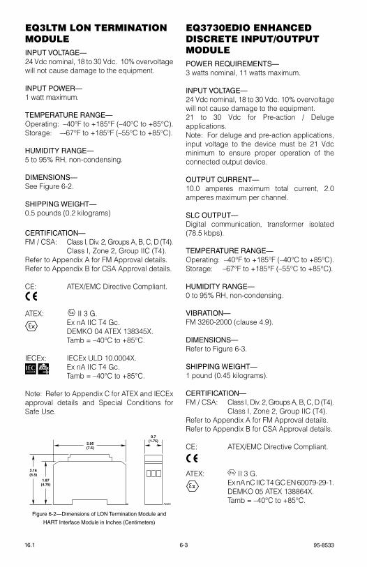
95-85336-316.1
eQ3ltM lon terMInAtIon MoDUleINPUT VOLTAGE—24 vdc nominal, 18 to 30 vdc. 10% overvoltage will not cause damage to the equipment.
INPUT POWER—1 watt maximum.
TEMPERATURE RANGE—Operating: –40°F to +185°F (–40°C to +85°C).storage: –-67°F to +185°F (–55°C to +85°C).
HUMIDITY RANGE—5 to 95% rH, non-condensing.
DIMENSIONS—see Figure 6-2.
SHIPPING WEIGHT—0.5 pounds (0.2 kilograms)
CERTIFICATION—FM / CsA: Class I, Div. 2, groups A, B, C, D (t4). Class I, Zone 2, group IIC (t4 ).refer to Appendix A for FM Approval details.refer to Appendix B for CsA Approval details.
Ce: AteX/eMC Directive Compliant.
AteX: FMAPPROVED
® II 3 g. ex nA IIC t4 gc. DeMkO 04 AteX 138345X. tamb = –40°C to +85°C.
IeCex: IeCex UlD 10.0004X. ex nA IIC t4 gc. tamb = –40°C to +85°C.
Note: refer to Appendix C for AteX and IeCex approval details and special Conditions for safe Use.
eQ3730eDIo enHAnceD DIScrete InpUt/oUtpUt MoDUlePOWER REQUIREMENTS—3 watts nominal, 11 watts maximum.
INPUT VOLTAGE—24 vdc nominal, 18 to 30 vdc. 10% overvoltage will not cause damage to the equipment.21 to 30 vdc for Pre-action / Deluge applications.Note: For deluge and pre-action applications, input voltage to the device must be 21 vdc minimum to ensure proper operation of the connected output device.
OUTPUT CURRENT—10.0 amperes maximum total current, 2.0 amperes maximum per channel.
SLC OUTPUT—Digital communication, transformer isolated (78.5 kbps).
TEMPERATURE RANGE—Operating: –40°F to +185°F (–40°C to +85°C).storage: –67°F to +185°F (–55°C to +85°C).
HUMIDITY RANGE—0 to 95% rH, non-condensing.
VIBRATION—FM 3260-2000 (clause 4.9).
DIMENSIONS—refer to Figure 6-3.
SHIPPING WEIGHT—1 pound (0.45 kilograms).
CERTIFICATION—FM / CsA: Class I, Div. 2, groups A, B, C, D (t4). Class I, Zone 2, group IIC (t4).refer to Appendix A for FM Approval details.refer to Appendix B for CsA Approval details.
Ce: AteX/eMC Directive Compliant.
AteX: FMAPPROVED II 3 g.
ex nA nC IIC t4 gC eN 60079-29-1. DeMkO 05 AteX 138864X. tamb = –40°C to +85°C.
0.7(1.75)
2.95(7.5)
1.87(4.75)
2.16(5.5)
A2253
Figure 6-2—Dimensions of LON Termination Module and
HART Interface Module in Inches (Centimeters)
FMAPPROVED
®
FMAPPROVED
®
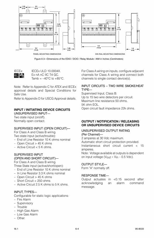
6-4 95-853316.1
IeCex: IeCex UlD 10.0004X. ex nA nC IIC t4 gC. tamb = –40°C to +85°C.
Note: refer to Appendix C for AteX and IeCex approval details and special Conditions for safe Use.refer to Appendix D for UsCg Approval details.
INPUT / INITIATING DEVICE CIRCUITSUNSUPERVISED INPUT—two state input (on/off).Normally open contact.
SUPERVISED INPUT (OPEN CIRCUIT)—For Class A and Class B wiring.two state input (active/trouble):– end of line resistor 10 k ohms nominal– Open Circuit > 45 k ohms– Active Circuit < 5 k ohms.
SUPERVISED INPUT (OPEN AND SHORT CIRCUIT)—For Class A and Class B wiring.three state input (active/short/open):– end of line resistor 10 k ohms nominal– In line resistor 3.3 k ohms nominal– Open Circuit > 45 k ohms– short Circuit < 250 ohms– Active Circuit 2.5 k ohms to 5 k ohms.
INPUT, TYPES—Configurable for static logic applications:– Fire Alarm– supervisory– trouble– High gas Alarm– low gas Alarm– Other.
For Class A wiring on inputs, configure adjacent channels for Class A wiring and connect both channels to single contact device(s).
INPUT CIRCUITS – TWO WIRE SMOKE/HEAT TYPE—supervised Input, Class B:Up to 15 two wire detectors per circuit.Maximum line resistance 50 ohms.5k ohm eOl.Open circuit fault impedance 22k ohms.
OUTPUT / NOTIFICATION / RELEASING OR UNSUPERVISED DEVICE CIRCUITS
UNSUPERVISED OUTPUT RATING (Per Channel)—2 amperes at 30 vdc maximum.Automatic short circuit protection provided.Instantaneous short circuit current < 15 amperes.Note: voltage available at outputs is dependent on input voltage (vout ≈ vin – 0.5 vdc).
OUTPUT STYLE—Form "A" normally off.
RESPONSE TIME—Output actuates in <0.15 second after acknowledging an alarm command message.
A B C A B C A B C A B C A B C A B C A B C A B C
1 6 1 6
1 2 3 4 5 6 7 8
A B C A B C A B C A B C A B C A B C A B C A B C
1 6 1 6
1 2 3 4 5 6 7 8
4.5(11.3)
5.02(12.7)
2.5(6.4)
1.35(3.4)
5.2(13.2)
1.66(4.2)
5.2(13.2) 1.9
(4.8)
4.5(11.3)
A2449
PANEL MOUNTING DIMENSIONS DIN RAIL MOUNTING DIMENSIONS
Figure 6-3—Dimensions of the EDIO / DCIO / Relay Module / AIM in Inches (Centimeters)
95-85336-516.1
SUPERVISED OUTPUT RATING-SIGNAL-ING CIRCUIT
MAXIMUM OUTPUT CURRENT (Per Channel)—2 amperes at 30 vdc maximum.Automatic short circuit protection provided.Instantaneous short circuit current < 15 amperes.
SUPERVISORY CURRENT (Per Channel)—reverse current monitored at 1.5 mA, ± 0.5 mA.
RESPONSE TIME—Output actuates in <0.15 second after acknowledging an alarm command message.
EOL RESISTORS—10 k ohms ±2 k ohms. each circuit must have an eOl resistor.
SIGNALING OUTPUT, TYPES—Configurable for device applications:– Continuous– 60 beats per minute– 120 beats per minute– temporal Pattern.Note: All eight channels are synchronized when programmed as a signaling output.
SUPERVISED OUTPUT RATING- RELEASING CIRCUIT
MAXIMUM OUTPUT CURRENT (Per Channel)—2 amperes at 30 vdc maximum.Automatic short circuit protection provided.Instantaneous short circuit current < 15 amperes.
SUPERVISORY CURRENT (Per Channel)—Monitored at 1.3 mA ±0.2 mA.
RESPONSE TIME—Output actuates in <0.15 second after acknowledging an alarm command message.
RELEASING OUTPUT, TYPES—Configurable for device applications:– Continuous– timed.
For Class A wiring on outputs, configure adjacent channels for Class A wiring and connect both channels to single output device(s).
noTe
eDIo SIL has the capability of monitoring solenoid circuits for shorts. The minimum solenoid inductance for correct operation is 100 mH. See Table 3-11 for a list of recommended solenoids.
eQ3700 DIScrete Io (DcIo) MoDUlePOWER REQUIREMENTS— 3 watts nominal, 11 watts maximum.
INPUT VOLTAGE—24 vdc nominal, 18 to 30 vdc. 10% overvoltage will not cause damage to the equipment.21 to 30 vdc for Pre-action / Deluge application.NOte: For deluge and pre-action applications, input voltage to the device must be 21 vdc minimum to ensure proper operation of the connected output device.
OUTPUT VOLTAGE—(Input voltage – 0.5 vdc) @ 2 amperes.
OUTPUT CURRENT—10.0 amperes maximum total current, 2.0 amperes maximum per channel.
LON COMMUNICATION—Digital communication, transformer isolated (78.5 kbps).
TEMPERATURE RANGE— Operating: –40°F to +185°F (–40°C to +85°C).storage: –67°F to +185°F (–55°C to +85°C).
HUMIDITY RANGE—5 to 95% rH, non-condensing.
DIMENSIONS— refer to Figure 6-3.
SHIPPING WEIGHT—1 pound (0.45 kilograms).
CERTIFICATION—FM / CsA: Class I, Div. 2, groups A, B, C, D (t4). Class I, Zone 2, group IIC (t4).
refer to Appendix A for FM Approval details.
refer to Appendix B for CsA Approval details.
FMAPPROVED
®
6-6 95-853316.1
Ce: AteX/eMC Directive Compliant.
AteX: FMAPPROVED
® II 3 g. ex nA nC IIC t4 gc. DeMkO 02 AteX 133864X. tamb = –40°C to +85°C.
IeCex: IeCex UlD 10.0004X. ex nA nC IIC t4 gc. tamb = –40°C to +85°C.
Note: refer to Appendix C for AteX and IeCex approval details and special Conditions for safe Use.
INPUT / INITIATING DEVICE CIRCUITS
UNSUPERVISED INPUT—two state input (on/off).Normally open contact.
SUPERVISED INPUT, CLASS B—two state input (active/trouble):– end of line resistor 10 k ohms nominal– Open Circuit > 45 k ohms– Active Circuit < 5 k ohms.
SUPERVISED INPUT, CLASS B—three state input (active/short/open):– end of line resistor 10 k ohms nominal– In line resistor 3.3 k ohms nominal– Open Circuit > 45 k ohms– short Circuit < 1.4 k ohms– Active Circuit 2.5 k ohms to 5 k ohms.
INPUT, TYPES—Configurable for fixed logic applications:– Fire Alarm– supervisory– trouble– High gas Alarm– low gas Alarm– Other.
OUTPUT / NOTIFICATION / RELEASING CIRCUITSUNSUPERVISED OUTPUT RATING—short circuit protected: 2 amperes at 30 vdc maximum.
SUPERVISED OUTPUT RATING—SIGNALING CIRCUIT
MAXIMUM OUTPUT CURRENT—2 amperes maximum, 15 Amp inrush.Automatic short circuit protection provided.
SUPERVISORY CURRENT—reverse current monitored at 3.0 mA, ± 2.0mA.
RESPONSE TIME—Output actuates in <0.15 second after acknowledging an alarm command message.
EOL RESISTORS—10 k ohms ±2 k ohms.
SIGNALING OUTPUT, TYPES—Configurable for device applications:– Continuous– 60 beats per second– 120 beats per second– temporal Pattern.
noTe
All eight channels are synchronized when programmed as a signaling output.
SUPERVISED OUTPUT RATING—RELEASING CIRCUIT
MAXIMUM OUTPUT CURRENT (Per Channel)—2 amperes maximum, 15 Amp inrush.Automatic short circuit protection provided.
SUPERVISORY CURRENT—Monitored at 3.0 mA ±2.0 mA.
RESPONSE TIME—Output actuates in <0.15 second after acknowledging an alarm command message.
RELEASING OUTPUT, TYPES—Configurable for device applications:– Continuous– timed.
FMAPPROVED
®
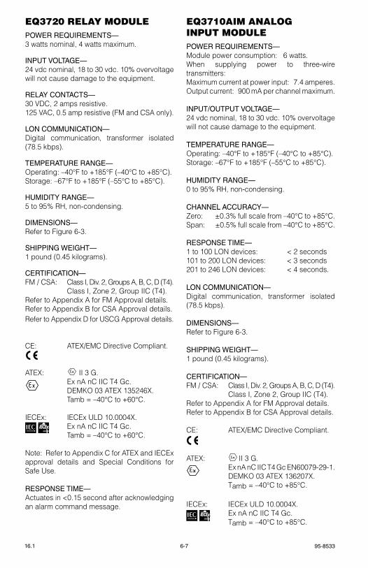
95-85336-716.1
eQ3720 relAy MoDUlePOWER REQUIREMENTS— 3 watts nominal, 4 watts maximum.
INPUT VOLTAGE—24 vdc nominal, 18 to 30 vdc. 10% overvoltage will not cause damage to the equipment.
RELAY CONTACTS—30 vDC, 2 amps resistive.125 vAC, 0.5 amp resistive (FM and CsA only).
LON COMMUNICATION—Digital communication, transformer isolated (78.5 kbps).
TEMPERATURE RANGE— Operating: –40°F to +185°F (–40°C to +85°C).storage: –67°F to +185°F (–55°C to +85°C).
HUMIDITY RANGE—5 to 95% rH, non-condensing.
DIMENSIONS— refer to Figure 6-3.
SHIPPING WEIGHT—1 pound (0.45 kilograms).
CERTIFICATION—FM / CsA: Class I, Div. 2, groups A, B, C, D (t4). Class I, Zone 2, group IIC (t4).refer to Appendix A for FM Approval details.refer to Appendix B for CsA Approval details.refer to Appendix D for UsCg Approval details.
Ce: AteX/eMC Directive Compliant.
AteX: FMAPPROVED II 3 g.
ex nA nC IIC t4 gc. DeMkO 03 AteX 135246X. tamb = –40°C to +60°C.
IeCex: IeCex UlD 10.0004X. ex nA nC IIC t4 gc. tamb = –40°C to +60°C.
Note: refer to Appendix C for AteX and IeCex approval details and special Conditions for safe Use.
RESPONSE TIME—Actuates in <0.15 second after acknowledging an alarm command message.
eQ3710AIM AnAlog InpUt MoDUlePOWER REQUIREMENTS— Module power consumption: 6 watts.When supplying power to three-wire transmitters:Maximum current at power input: 7.4 amperes.Output current: 900 mA per channel maximum.
INPUT/OUTPUT VOLTAGE—24 vdc nominal, 18 to 30 vdc. 10% overvoltage will not cause damage to the equipment.
TEMPERATURE RANGE— Operating: –40°F to +185°F (–40°C to +85°C).storage: –67°F to +185°F (–55°C to +85°C).
HUMIDITY RANGE—0 to 95% rH, non-condensing.
CHANNEL ACCURACY—Zero: ±0.3% full scale from –40°C to +85°C.span: ±0.5% full scale from –40°C to +85°C.
RESPONSE TIME—1 to 100 lON devices: < 2 seconds101 to 200 lON devices: < 3 seconds201 to 246 lON devices: < 4 seconds.
LON COMMUNICATION—Digital communication, transformer isolated (78.5 kbps).
DIMENSIONS— refer to Figure 6-3.
SHIPPING WEIGHT—1 pound (0.45 kilograms).
CERTIFICATION—FM / CsA: Class I, Div. 2, groups A, B, C, D (t4). Class I, Zone 2, group IIC (t4).refer to Appendix A for FM Approval details.refer to Appendix B for CsA Approval details.
Ce: AteX/eMC Directive Compliant.
AteX: FMAPPROVED II 3 g.
ex nA nC IIC t4 gc eN60079-29-1. DeMkO 03 AteX 136207X. tamb = –40°C to +85°C.
IeCex: IeCex UlD 10.0004X. ex nA nC IIC t4 gc. tamb = –40°C to +85°C.
FMAPPROVED
®
FMAPPROVED
®

6-8 95-853316.1
Note: refer to Appendix C for AteX and IeCex approval details and special Conditions for safe Use.
refer to Appendix D for UsCg Approval details.
HArt InterFAce MoDUle (HIM)INPUT VOLTAGE—24 vdc nominal, 18 to 30 vdc. 10% overvoltage will not cause damage to the equipment.
INPUT POWER—1.0 watt maximum.
INPUT/OUTPUT CURRENT—Operating: 4 -20 mA.Maximum: 0-30 mA.
TEMPERATURE RANGE—Operating: –40°F to +185°F (–40°C to +85°C).storage: –-67°F to +185°F (–55°C to +85°C).
HUMIDITY RANGE—5 to 95% rH, non-condensing.
DIMENSIONS—see Figure 6-2.
SHIPPING WEIGHT—0.5 pounds (0.2 kilograms)
CERTIFICATION—FM / CsA: Class I, Div. 2, groups A, B, C, D (t4). Class I, Zone 2, group IIC (t4 ).
Ce: AteX/eMC Directive Compliant.
AteX FMAPPROVED
® II 3 g. ex nA IIC t4 gc. DeMkO 04 AteX 136507X. tamb = –40°C to +85°C.
IeCex: IeCex UlD 10.0004X. ex nA IIC t4 gc. tamb = –40°C to +85°C.
Note: refer to Appendix C for AteX and IeCex approval details and special Conditions for safe Use.
eQ21XXpS poWer SUpplIeSINPUT VOLTAGE—selectable for 120, 208 or 240 vac input power, ±10%.
INPUT CURRENT—60 Hz Models:eQ2110Ps: 4 amps at 120 vACeQ2130Ps: 11 / 6 / 6 amps at 120 / 208 / 240 vACeQ2175Ps: 24 / 15 / 12 amps at 120 / 208 / 240 vAC.
50 Hz Models:eQ2111Ps: 4 amps at 120 vACeQ2131Ps: 6 amps at 240 vACeQ2176Ps: 12 amps at 240 vAC.
OUTPUT CURRENT—eQ2110Ps / eQ2111Ps: 10 amperes at 24 vDCeQ2130Ps / eQ2131Ps: 30 amperes at 24 vDCeQ2175Ps / eQ2176Ps: 75 amperes at 24 vDC.
POWER CONSUMPTION—eQ2110Ps / eQ2111Ps: 46 WattseQ2130Ps / eQ2131Ps: 140 WattseQ2175Ps / eQ2176Ps: 349 Watts.
TEMPERATURE RANGE—Operating: +32°F to +122°F (0°C to +50°C)storage: -40°F to +185°F (-40°C to +85°C).
HUMIDITY RANGE—5 to 95% rH, non-condensing.
DIMENSIONS—in Inches (Centimeters) Width Height DeptheQ211xPs: 19 (48.3) 7 (17.8) 15 (38.1)eQ213xPs: 19 (48.3) 14 (35.6) 15 (38.1)eQ217xPs: 19 (48.3) 14 (35.6) 15 (38.1)
noTe
Power supplies are designed for mounting in a standard 19 inch rack. optional mounting hardware is available for floor or wall mount applications.
CERTIFICATION—FM / CsA: Ordinary locations.
FMAPPROVED
®
FMAPPROVED
®
95-85336-916.1
eQp2XX0pS(–X) poWer SUpplIeSINPUT VOLTAGE—eQP2110Ps(-P), eQP2120Ps(-B): Auto selectable for 120/220 vac, –15%, +10%; 60/50 Hz, single phase;eQP2410Ps(-P) Converter: 24 vdc, –15%, +10%.
INPUT CURRENT—eQP2110Ps(-P): 3.2 A max @ 120 vac 1.7 A max @ 220 vaceQP2120Ps(-B): 6.6 A max @ 120 vac 3.6 A max @ 220 vaceQP2410Ps(-P): 15.7 A @ max @ 24 vdc
OUTPUT VOLTAGE—24.5 vdc nominal, 24.5 to 28.0 vdc.
OUTPUT CURRENT—eQP2110Ps(-P): 10 AeQP2120Ps(-B): 20 AeQP2410Ps(-P): 10 A
TEMPERATURE RANGE (ALL MODELS)—Operating: –13°F to +131°F (–25°C to +55°C)(All Applications)storage: –40°F to +185°F (–40°C to +85°C)
HUMIDITY RANGE—5 to 95% rH at 25°C, non-condensing.
DIMENSIONS—In Inches (Centimeters) Width Height DeptheQP2110Ps(-P): 3.35(8.5) 5.2(13.0) 5.0(12.5)eQP2120Ps(-B): 3.54(9) 5.2(13.0) 5.0(12.5)eQP2410Ps(-P): 3.2(8.0) 5.2(13.0) 5.0(12.5)
noTe
Power supplies are designed for DIn rail or panel mounting (–B or –P suffix).
CERTIFICATION—FM / CsA: Ordinary locations.UsCg: refer to Appendix D for details.
reDUnDAncy MoDUle QUInt–DIoDe/40TEMPERATURE RANGE—Operating: –13°F to +131°F (–25°C to +55°C)(All Applications)storage: –40°F to +185°F (–40°C to +85°C).
HUMIDITY RANGE—
5 to 95% rH, non-condensing.
DIMENSIONS—
in Inches (Centimeters) Width Height Depth 2.4 (6.2) 4 (10.2) 3.3 (8.4)

6-10 95-853316.1
eQ21XXpSM poWer SUpply MonItorINPUT VOLTAGE—
24 vdc nominal, 18 to 30 vdc.
POWER CONSUMPTION—
2.0 watts maximum.
MEASUREMENT RANGE—
AC voltage: 240 vac maximum.DC Battery Charging Current: 75 amperes maximum.
OUTPUT—Digital communication, transformer isolated (78.5 k bps).
TEMPERATURE RANGE—Operating: +32°F to +122°F (0°C to +50°C)storage: –67°F to +185°F (–55°C to +85°C).
HUMIDITY RANGE—
5 to 95% rH, non-condensing.
DIMENSIONS—
see Figure 6-4.
CERTIFICATION—
FM / CsA: Ordinary locations.
eQ22xxIDc/IDcgF InItIAtIng DeVIce cIrcUItINPUT VOLTAGE—24 vdc nominal, 18 to 30 vdc. 10% overvoltage will not cause damage to the equipment.
INPUT POWER—4.0 watts maximum.
INPUTS—two supervised non-incendive digital inputs (sealed or unsealed switch or relay contacts). 10 kohm eOl resistors are required.
OUTPUTS—Digital communication, transformer isolated (78.5 kbps).
TEMPERATURE RANGE—Operating: –40°F to +167°F (–40°C to +75°C).storage: –67°F to +185°F (–55°C to +85°C).
HUMIDITY RANGE—
5 to 95% rH, non-condensing.
VIBRATION—
FM 3260.
DIMENSIONS—
see Figure 6-5.
B C
J1 J3
4(10.2)
8.5(21.6)
9(22.9)
2.5(6.4)
2.25(5.7)
A2038
Figure 6-4—Dimensions of Power Supply Monitor in Inches
(CM)
3.46(8.8)
4.7(11.9)
2.7(6.9)
5.2(13.2)
5.86(14.9)
6.57(16.7)
1.28(3.3)
A2523
Figure 6-5—Dimensions of Tall Cover Junction Box in Inches
(Centimeters)

95-85336-1116.1
CERTIFICATION—FM / CsA: Class I, Div. 1, groups B, C, D. Class I, Zone 1, group IIC. Class II/III, Div. 1, groups e, F, g. Class I, Div. 2, groups A, B, C, D (t4). Class I, Zone 2, group IIC (t4 ). Class II/III, Div. 2, groups F & g (t4). NeMA/type 4X.refer to Appendix A for FM Approval details.refer to Appendix B for CsA Approval details.
Ce: AteX/eMC Directive Compliant.
refer to Appendix C for AteX Approval details.
AteX: 0539 FMAPPROVED
® II 2 g ex db IIC t4-t6 DeMkO 02 AteX 131321X t6 (tamb = –55°C to +50°C) t5 (tamb = –55°C to +65°C) t4 (tamb = –55°C to +75°C) IP66
IeC: IeCex UlD 10.0010 ex d IIC t4-t6 gb t6 (tamb = –55°C to +50°C) t5 (tamb = –55°C to +65°C) t4 (tamb = –55°C to +75°C)
refer to Appendix e for Ce Mark details.
eQ2220gFM groUnD FAUlt MonItor
INPUT VOLTAGE—24 vdc nominal, 18 to 30 vdc. 10% overvoltage will not cause damage to the equipment.
INPUT POWER—1.0 watt maximum.
OUTPUT—Form C NO/NC relay contact rated 1 ampere (resistive) at 30 vdc maximum.
TEMPERATURE RANGE—Operating: –40°F to +185°F (–40°C to +85°C).storage: –-67°F to +185°F (–55°C to +85°C).
HUMIDITY RANGE—5 to 95% rH, non-condensing.
DIMENSIONS—see Figure 6-6.
SHIPPING WEIGHT—0.5 pounds (0.2 kilograms)
CERTIFICATION—FM / CsA: Class I, Div. 2, groups A, B, C, D (t4). Class I, Zone 2, group IIC (t4 ).
refer to Appendix A for FM Approval details.refer to Appendix B for CsA Approval details.
Ce: AteX/eMC Directive Compliant.
AteX: FMAPPROVED
® II 3 g ex nC IIC t4 gc DeMkO 03 AteX 136222X tamb = –40°C to +85°C
IeCex: IeCex UlD 10.0004X ex nC IIC t4 gc tamb = –40°C to +85°C
Note: refer to Appendix C for AteX Approval and Appendix e for Ce Mark details and special Conditions for safe Use.
refer to Appendix D for UsCg Approval details.
FMAPPROVED
®
FMAPPROVED
®
FMAPPROVED
®
FMAPPROVED
®
1.2(3.0)
2.9(7.4)
1.75(4.4)
2.1(5.3)
A2237
Figure 6-6—Dimensions of Ground Fault Monitor
in Inches (Centimeters)

6-12 95-853316.1
eQ22XXDcU AnD eQ22XXDcUeX DIgItAl coMMUnIcAtIon UnItINPUT VOLTAGE—24 vdc nominal, 18 to 30 vdc. 10% overvoltage will not cause damage to the equipment.
POWER CONSUMPTION—DCU with toxic gas sensor/transmitter: 95 ma max.
DCU with transmitter and combustible gas sensor: 180 ma maximum during normal operation, 500 ma during startup.
INPUTS—4 - 20 mA analog signal, non-intrusive calibration.
OUTPUTS—Digital communication, transformer isolated (78.5 kbps).
TEMPERATURE RANGE—Operating: –40°F to +167°F (–40°C to +75°C).storage: –67°F to +185°F (–55°C to +85°C).
HUMIDITY RANGE—5 to 95% rH, non-condensing.
VIBRATION—FM 6310/6320.
DIMENSIONS— see Figure 6-5.
CERTIFICATION—FM / CsA: Class I, Div. 1, groups B, C, D. Class I, Zone 1, group IIC. Class I, Div. 2, groups A, B, C, D (t4). Class I, Zone 2, group IIC (t4 ). Class II/III, Div. 1 & 2 (for use with Model stB). NeMA/type 4X (for use with Model stB).refer to Appendix A for FM Approval details.refer to Appendix B for CsA Approval details.
Ce: AteX/eMC Directive Compliant.
AteX: 0539 FMAPPROVED
® II 2 g ex db IIC t4-t6 eN 60079-29-1 DeMkO 02 AteX 131321X t6 (tamb = –55°C to +50°C) t5 (tamb = –55°C to +65°C) t4 (tamb = –55°C to +75°C) IP66refer to Appendix C for AteX Approval details.
Special Conditions for Safe Use (X):the device has an ambient temperature rating for performance of –40°C to +75°C.IeC: IeCex UlD 10.0010 ex d IIC t4-t6 gb t6 (tamb = –55°C to +50°C) t5 (tamb = –55°C to +65°C) t4 (tamb = –55°C to +75°C)refer to Appendix D for UsCg Approval details. refer to Appendix e for Ce Mark details.
FMAPPROVED
®
FMAPPROVED
®
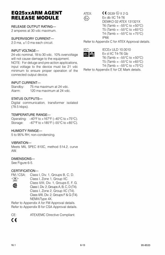
95-85336-1316.1
eQ25xxArM Agent releASe MoDUle
RELEASE OUTPUT RATING—2 amperes at 30 vdc maximum.
SUPERVISORY CURRENT—2.0 ma, ±1.0 ma each circuit.
INPUT VOLTAGE—24 vdc nominal, 18 to 30 vdc. 10% overvoltage will not cause damage to the equipment.NOte: For deluge and pre-action applications, input voltage to the device must be 21 vdc minimum to ensure proper operation of the connected output device.
INPUT CURRENT—standby: 75 ma maximum at 24 vdc.Alarm: 120 ma maximum at 24 vdc.
STATUS OUTPUTS—Digital communication, transformer isolated (78.5 kbps).
TEMPERATURE RANGE—Operating: –40°F to +167°F (–40°C to +75°C).storage: –67°F to +185°F (–55°C to +85°C).
HUMIDITY RANGE—5 to 95% rH, non-condensing.
VIBRATION—Meets MIl sPeC 810C, method 514.2, curve AW.
DIMENSIONS— see Figure 6-5.
CERTIFICATION—FM / CsA: Class I, Div. 1, groups B, C, D. Class I, Zone 1, group IIC. Class II/III, Div. 1, groups e, F, g. Class I, Div. 2, groups A, B, C, D (t4). Class I, Zone 2, group IIC (t4 ). Class II/III, Div. 2, groups F & g (t4). NeMA/type 4X.refer to Appendix A for FM Approval details.refer to Appendix B for CsA Approval details.
Ce: AteX/eMC Directive Compliant.
AteX: 0539 FMAPPROVED
® II 2 g ex db IIC t4-t6 DeMkO 02 AteX 131321X t6 (tamb = –55°C to +50°C) t5 (tamb = –55°C to +65°C) t4 (tamb = –55°C to +75°C) IP66refer to Appendix C for AteX Approval details.
IeC: IeCex UlD 10.0010 ex d IIC t4-t6 gb t6 (tamb = –55°C to +50°C) t5 (tamb = –55°C to +65°C) t4 (tamb = –55°C to +75°C)refer to Appendix e for Ce Mark details.
FMAPPROVED
®
FMAPPROVED
®
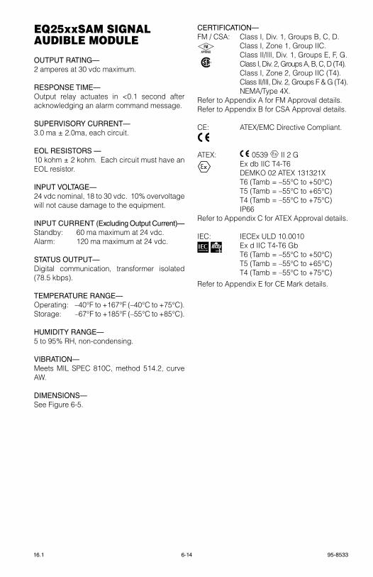
6-14 95-853316.1
eQ25xxSAM SIgnAl AUDIBle MoDUle
OUTPUT RATING—2 amperes at 30 vdc maximum.
RESPONSE TIME—Output relay actuates in <0.1 second after acknowledging an alarm command message.
SUPERVISORY CURRENT—3.0 ma ± 2.0ma, each circuit.
EOL RESISTORS —10 kohm ± 2 kohm. each circuit must have an eOl resistor.
INPUT VOLTAGE—24 vdc nominal, 18 to 30 vdc. 10% overvoltage will not cause damage to the equipment.
INPUT CURRENT (Excluding Output Current)—standby: 60 ma maximum at 24 vdc.Alarm: 120 ma maximum at 24 vdc.
STATUS OUTPUT—Digital communication, transformer isolated (78.5 kbps).
TEMPERATURE RANGE—Operating: –40°F to +167°F (–40°C to +75°C).storage: –67°F to +185°F (–55°C to +85°C).
HUMIDITY RANGE—5 to 95% rH, non-condensing.
VIBRATION—Meets MIl sPeC 810C, method 514.2, curve AW.
DIMENSIONS— see Figure 6-5.
CERTIFICATION—FM / CsA: Class I, Div. 1, groups B, C, D. Class I, Zone 1, group IIC. Class II/III, Div. 1, groups e, F, g. Class I, Div. 2, groups A, B, C, D (t4). Class I, Zone 2, group IIC (t4 ). Class II/III, Div. 2, groups F & g (t4). NeMA/type 4X.refer to Appendix A for FM Approval details.refer to Appendix B for CsA Approval details.
Ce: AteX/eMC Directive Compliant.
AteX: 0539 FMAPPROVED
® II 2 g ex db IIC t4-t6 DeMkO 02 AteX 131321X t6 (tamb = –55°C to +50°C) t5 (tamb = –55°C to +65°C) t4 (tamb = –55°C to +75°C) IP66refer to Appendix C for AteX Approval details.
IeC: IeCex UlD 10.0010 ex d IIC t4-t6 gb t6 (tamb = –55°C to +50°C) t5 (tamb = –55°C to +65°C) t4 (tamb = –55°C to +75°C)refer to Appendix e for Ce Mark details.
FMAPPROVED
®
FMAPPROVED
®
95-85336-1516.1
eQ24xxne netWorK eXtenDer
INPUT VOLTAGE—24 vdc nominal, 18 to 30 vdc. 10% overvoltage will not cause damage to the equipment.
POWER CONSUMPTION—2.2 watts nominal at 24 vdc, 2.7 watts maximum.
INPUTS/OUTPUTS—Digital, transformer isolated (78.5k Baud).
TEMPERATURE RANGE—Operating: –40°F to +167°F (–40°C to +75°C)storage: –67°F to +185°F (–55°C to +85°C).
HUMIDITY—5 to 95% rH at 70°C.
DIMENSIONS—see Figure 6-7.
CERTIFICATION—FM / CsA: Class I, Div. 1, groups B, C, D. Class I, Zone 1, group IIC. Class II/III, Div. 1, groups e, F, g. Class I, Div. 2, groups A, B, C, D (t4). Class I, Zone 2, group IIC (t4 ). Class II/III, Div. 2, groups F & g (t4). NeMA/type 4X. refer to Appendix A for FM Approval details.refer to Appendix B for CsA Approval details.
Ce: AteX/eMC Directive Compliant.
AteX: 0539 FMAPPROVED II 2 g.
ex db IIC t4-t6 DeMkO 02 AteX 131321X t6 (tamb = –55°C to +50°C) t5 (tamb = –55°C to +65°C) t4 (tamb = –55°C to +75°C) IP66refer to Appendix C for AteX Approval details.
IeC: IeCex UlD 10.0010 ex d IIC t4-t6 gb t6 (tamb = –55°C to +50°C) t5 (tamb = –55°C to +65°C) t4 (tamb = –55°C to +75°C)
refer to Appendix D for UsCg Approval details. refer to Appendix e for Ce Mark details.
FMAPPROVED
®
FMAPPROVED
®
3.46(8.8)
4.7(11.9)
2.7(6.9)
5.2(13.2)
5.86(14.9)
A2531
3.77(9.6)
1.28(3.3)
Figure 6-7—Dimensions of Short Cover Junction Box
in Inches (Centimeters)

6-16 95-853316.1
eQ3750ASH ADDreSSABle SMoKe & HeAt MoDUleFor complete information regarding the AsH Module, refer to instruction manual number 95-8654.
coMBUStIBle gAS SenSorrefer to the Combustible gas sensor specification Data sheet, form 90-1041, for specifications.
electrocHeMIcAl SenSorSrefer to the electrochemical gas sensor specification Data sheet, form 90-1079, for specifications. electrochemical sensors available from Det-tronics include Hydrogen sulfide, Oxygen, Carbon Monoxide, Chlorine, sulfur Dioxide, and Nitrogen Dioxide.
eQ21XXpS poWer SUpplythe eQ21xxPs rectifier / Power supply has many inherent advantages such as voltage regulation, high efficiency, high power factor and short circuit protection.
these chargers provide separate adjustable voltages for floating or equalizing lead or nickel-cadmium cells. An equalize switch is located on the front panel of thecharger for manual activation or a multi-mode electronic timer can be used for automatic activation.
steady state output voltage remains within +/- 1/2% of the setting from no load to full load and for AC input voltages within +/- 10% of the nominal input voltage. the power supply is internally filtered to be no greater than 32dBrn (“C” message weighting) and 30 millivolts rMs for all conditions on input voltage and output load with or without batteries connected. this allows the A36D to be used as a battery eliminator.

95-8533A-116.1
AppenDIX A FM APPROVAL DESCRIPTION
HAzARDOUS LOCATIONS
• refer to Figures A-1 and A-2 for system Classification details.• eQxxxxeM versions rated nonincendive for Class I, Div. 2, groups A, B, C, D (t4A).
FIRE DETECTION & RELEASING
• National Fire Alarm Code performance verified per ANsI/NFPA 72-2010. refer to table A-1 for supervision characteristics.
• refer to the Model X3301, X5200, X2200 and X9800 manuals (see table 2-4) for further FM flame performance details. Additional 2 second response time applied for system communication.
• Models eQ3700 series and eQ22xxArM series are Approved as agent releasing circuits and are Approved for use with the following automatic deluge and pre-action solenoids:
GAS DETECTION
• Combustible gas Performance verified for 0 to 100% lFl methane-in-air atmospheres per FM 6310/6320. Accuracy: ±3% lFl from 0 to 50% lFl, ±5% lFl from 51% to 100% lFl. For the Model PIreCl, refer to the PIreCl manual (form number 95-8526) for further FM gas performance details.
noTe: Detector electronics combustible gas detection K factors are not FM verified.
• H2s toxic gas Performance verified 0 to 20, 50 or 100 ppm per FM requirements. Accuracy: ±2 ppm from 0 to 20 ppm, ±10% of concentration from 21 to 100 ppm. Models C7064e4012 and C7064e5012 Hydrogen sulfide (H2s) sensors explosion-proof for Class I, Div. 1, groups C and D Hazardous (Classified) locations per FM 3615. Model C7064e5014 Hydrogen sulfide (H2s) sensors explosion-proof for Class I, Div. 1, groups B, C and D Hazardous (Classified) locations per FM 3615. Operating temperature limits are –40°C to +40°C.
noTe: Sensor cross sensitivity has not been verified by FM.
• Calibration of the above listed sensors has been FM verified using the respective eQ22xxDCU, eQ22xxDCUeX, and PIreCl with the Det-tronics 225130-001 (50% lFl methane) and/or 227115-001 H2s Calibration kits.
• the eQ22xxDCU series can be used with any FM Approved 4-20 ma device.
Solenoids
FM Solenoid Group Manufacturer Model
B AsCO t8210A107
D AsCO 8210g207
e skinner 73218BN4UNlvNOC111C2
F skinner 73212BN4tNlvNOC322C2
g skinner 71395sN2eNJ1NOH111C2
H viking 11601

A-2 95-853316.1
noTe
FM Approval of the 4-20 ma input does not include or imply approval of the gas detection apparatus such as sensors, transmitters, or devices connected to the system. In order to maintain FM Approval of the system, all 4-20 ma gas detection instruments connected to the input must also be FM Approved.
noTe
FM Approval allows the presence and operation of serial/ethernet communications software in the Controller (MoDBUS TCP/IP, Allen Bradley protocols, etc.); however, the communications functions are not included in the Approval.
EQPSS SUPERVISING SYSTEM
• National Fire Alarm Code performance verified per ANsI/NFPA 72-2002. refer to Figures A-2 and B-2 for eQPss supervising system architecture.
• Det-tronics only to integrate proprietary eQPss supervising system per Det-tronics Procedures 5072 and 5073.
EQP SYSTEM MODEL 000523-009 & 000523-010
• the system consists of: 1 x eQP2120Ps-B Power supply, primary; 2 x eQP2410Ps-P Converter, secondary; 2 x QUINt–DIODe/40 redundancy module; 1 x eQ2220gFM ground Fault Monitor
1 x eQ3XXX Controller (000523-009) 0 x eQ3XXX Controller (000523-010) 0 x eQ3710AIM Module & 1 x eQ3730eDIO Module (000523-009) 2 x eQ3710AIM Modules & 2 x eQ3730eDIO Modules (000523-010)
• the system is mounted within 60H x 36W x 16D stainless steel (type 316), Nrtl labeled NeMA 4X rated enclosure. the enclosure shall be lockable by key lock or padlock.
• eQP system models 000523-009 & 000523-010 are suitable for Cl I, Div. 2, grPs A, B, C & D (t4); Cl I, Zone 2, grP IIC (t4) Hazardous (Classified) locations; tamb = –20°C to +49°C.
• Modifications to enclosure (such as conduit entry holes, windows etc.) are permitted when implemented by the manufacturer of the enclosure.
95-8533A-316.1
Table A-1—Circuit Classifications
Signaling Path NFPA 72: 2010 Supervision
local Operating Network (lON) signaling line Circuit (slC): Class X
Power Distribution Module, Input Power
supervised. loss of power per ANsI/NFPA 72, Cl. 10.17.3.
Power Distribution Module, Controller Power Output
supervised. loss of power per ANsI/NFPA 72, Cl. 10.17.3.
Power Distribution Module, Field Device Power Output
supervised. single open or ground-fault per ANsI/NFPA 72, Cl. 10.17.1.
Power Distribution Module, local Field Device Power Output
Unsupervised per ANsI/NFPA 72, Cl. 10.17.1, exception #10.17.1.8 & #10.17.1.9.
Power supply Monitor, Input Power supervised. loss of power per ANsI/NFPA 72, Cl. 10.17.3.
Power supply Monitor, Output Power
supervised (via Controller for opens). single open or ground-fault per ANsI/NFPA 72, Cl. 10.17.1.
Power supply Monitor, Charger supervised. loss of charger per NFPA Cl. 10.5.9.6.
Power supply Monitor, Battery supervised. loss of battery per NFPA Cl. 10.17.3.
Controller, Digital Input Unsupervised per ANsI/NFPA 72, Cl. 10.17.1, exception #10.17.1.8 & #10.17.1.9.
Controller, relay Output Unsupervised per ANsI/NFPA 72, Cl. 10.17.1, exception #10.17.1.8 & #10.17.1.9.
Controller, trouble relay Output Unsupervised per ANsI/NFPA 72, Cl. 10.17.1, exception #10.17.1.8 & #10.17.1.9.
Controller, 232 expansion Output (sIl or Non-sIl)
Unsupervised per ANsI/NFPA 72, Cl. 10.17.1, exception #10.17.1.8 & #10.17.1.9.
Controller, ethernet expansion Output (sIl or Non-sIl)
Unsupervised per ANsI/NFPA 72, Cl. 10.17.1, exception #10.17.1.8 & #10.17.1.9.
Controller, slC485 expansion Output, including optional fiber optic equipment (sIl or Non-sIl)
Class B (single Channel single-Mode Fiber)Class X (Multi-Mode Fiber or Dual Channel single-Mode Fiberor Dual Channel Wire)
redundant Controller Connector, rs-232 (sIl or Non-sIl)
Unsupervised per ANsI/NFPA 72, Cl. 10.17.1, exception #10.17.1.8 & #10.17.1.9.
relay Module, Output Unsupervised, for connection with ancillary equipment only.
enhanced Discrete I/O, Input (software configurable, sIl or Non-sIl)
Unsupervised per ANsI/NFPA 72, Cl. 10.17.1, exception #10.17.1.8 & #10.17.1.9.
Initiating Device Circuit (IDC): Class A or Class B
enhanced Discrete I/O, Output (software configurable, sIl or Non-sIl)
Unsupervised per ANsI/NFPA 72, Cl. 10.17.1, exception #10.17.1.8 & #10.17.1.9.
Notification Appliance Circuit (NAC): Class A or Class B
supervised solenoids (Class A or Class B):single open or ground-fault per ANsI/NFPA 72, Cl. 10.17.1.group B: AsCO t8210A107 group D: AsCO 8210g207 group e: skinner 73218BN4UNlvNOC111C2 group F: skinner 73212BN4tNlvNOC322C2 group g: skinner 71395sN2eNJ1NOH111C2 group H: viking 11601
A-4 95-853316.1
Table A-1—Circuit Classifications-Continued
signaling Path NFPA 72: 2010 supervision
Discrete I/O, Input (software configurable)
Unsupervised per ANsI/NFPA 72, Cl. 10.17.1, exception #10.17.1.8 & #10.17.1.9.
Initiating Device Circuit (IDC): Class B
Discrete I/O, Output (software configurable)
Unsupervised per ANsI/NFPA 72, Cl. 10.17.1, exception #10.17.1.8 & #10.17.1.9.
Notification Appliance Circuit (NAC): Class B
supervised solenoids: single open or ground-fault per ANsI/NFPA 72, Cl. 10.17.1.group B: AsCO t8210A107 group D: AsCO 8210g207 group e: skinner 73218BN4UNlvNOC111C2 group F: skinner 73212BN4tNlvNOC322C2 group g: skinner 71395sN2eNJ1NOH111C2 group H: viking 11601
Analog Input Module (sIl or Non-sIl) Initiating Device Circuit (IDC): Class B
IDC Input Initiating Device Circuit (IDC): Class B
IDCgF Input (Channel 2 only) Unsupervised per ANsI/NFPA 72, Cl. 10.17.1, exception #10.17.1.8 & #10.17.1.9.
sAM Output
ArM Output
Notification Appliance Circuit (NAC): Class B
supervised solenoids: single open or ground-fault per ANsI/NFPA 72, Cl. 10.17.1group B: AsCO t8210A107 group D: AsCO 8210g207 group e: skinner 73218BN4UNlvNOC111C2 group F: skinner 73212BN4tNlvNOC322C2 group g: skinner 71395sN2eNJ1NOH111C2 group H: viking 11601
AsH loop (smoke & Heat loop) signaling line Circuit (slC): Class A or Class B (single spur)
AsH loop (smoke & Heat loop) with Isolators signaling line Circuit (slC): Class X
AsH loop (smoke & Heat loop) with Isolators signaling line Circuit (slC): Class B (single spur)
AsH - Addressable smoke and Heat Module Input (software configurable)
Unsupervised per ANsI/NFPA 72, Cl. 10.17.1,exception #10.17.1.8 & #10.17.1.9.
Initiating Device Circuit (IDC): Class A
AsH - Addressable smoke and Heat Module Input - smoke detector inputs
Initiating Device Circuit (IDC): Class A (Apollo)
AsH - Addressable smoke and Heat Module Output (software configurable)
Unsupervised per ANsI/NFPA 72, Cl. 10.17.1,exception #10.17.1.8 & #10.17.1.9.
Notification Appliance Circuit (Apollo): Class A
A-5 95-853316.1
Figure A-1 (System Drawing 007545-001T)
A-6 95-853316.1
Figure A-2 (System Drawing 007545-001)

B-1 95-853316.1
AppenDIX B CSA INTERNATIONAL CERTIFICATION DESCRIPTION
HAzARDOUS LOCATIONS
• refer to Figures B-1 and B-2 for system Classification details.• eQxxxxeM versions rated Class I, Div. 2, groups A, B, C, D (t4A).
GAS DETECTION
• Combustible gas Performance verified for 0 to 100% lFl methane-in-air atmospheres per CsA C22.2 No. 152. Accuracy: ±3% lFl from 0 to 50% lFl, ±5% lFl from 51% to 100% lFl. For the Model PIreCl, refer to the PIreCl manual (form number 95-8526) for further CsA gas performance details.
noTe: Detector electronics combustible gas detection K factors are not CSA verified.
• Calibration of the devices has been CsA verified using the respective eQ22xxDCU, eQ22xxDCUeX and PIreCl series with the Det-tronics 225130-001 (50% lFl methane) and 227115-001 H2s Calibration kits.
• the eQ22xxDCU series can be used with any CsA Certified 4-20 ma device.

95-8533B-216.1
noTe
CSA Certification of the 4-20 ma input does not include or imply approval of the gas detection apparatus such as sensors, transmitters, or devices connected to the system. In order to maintain CSA Certification of the system, all 4-20 ma gas detection instruments connected to the input must also be CSA Certified.
noTe
CSA Certification allows the presence and operation of serial/ethernet communications software in the Controller (MoDBUS TCP/IP, Allen Bradley protocols, etc.); however, the communications functions are not included in the Certification.
B-3 95-853316.1
Figure B-1 (Drawing 007546-001P)
B-4 95-853316.1
Figure B-2 (Drawing 007546-001)

C-1 95-853316.1
AppenDIX cATEX AND IECEX CERTIFICATION
ATEX AND IECEX CERTIFICATION DETAILS
the eagle Quantum Premier Fire and gas Detection / releasing system was tested and certified to hazardous location and combustible gas performance standards. refer to Figure C-1 for system classification details.
the AteX/IeCex certified eagle Quantum Premier system field devices eQ22..., eQ24... and eQ25... are in compliance with the following standards:– IeC 60079-0: 2011– eN 60079-0: 2012– IeC/eN 60079-1: 2010– eN 60079-29-1: 2007– eN 60079-29-4: 2010 (eQ3XXX Only)
the AteX/IeCex certified ex n modules of the eQP system are in compliance with the following standards:– IeC 60079-0: 2011– eN 60079-0: 2012– IeC/eN 60079-15: 2010– eN 60079-29-1: 2007– eN 60079-29-4: 2010 (eQ3XXX Only)
For all ATEX/IECEx certified Ex n modules in the EQP system, the following Special Conditions for Safe Use apply:the ambient temperature range is limited for eQ3XXX:– From –40°C to +70°C if any of the output relays 1-7 (terminals 21-41) is used (energized).– From –40°C to +80°C if all output relays 1-7 (terminals 21-41) remain open-contacted and de-energized.
For compliance to eN 60079-29-1/-4, the relevant ex n module must be used with gas detection apparatus that are certified for compliance to eN60079-29-1/-4 and that provide a suitable linear 4-20 mA output, relay contact output or lON communication output relative to the %lFl of the available gas in the area of the gas detection apparatus. see the Manual for details on the required connection parameters.
the eQP ex n modules shall be used in an area of no more than pollution degree 2 conforming to IeC 60664-1, and in an enclosure with a tool removable cover that complies with all relevant requirements of IeC/eN 60079-15, rated at least IP54, and shall be connected to supply circuits where the rated voltage cannot be exceeded by 40% caused by transient disturbances.

95-8533C-216.1
PERFORMANCE TESTING TO EN 60079-29-1: 2007 AND EN 60079-29-4: 2010
the measuring function of the eQ3XXX Controller, according to Annex II paragraph 1.5.5, 1.5.6 and 1.5.7 of the Directive 94/9/eC, was covered in this type examination Certificate in the following configurations: 1. Controller Model eQ3XXX with eQ3710AIM or eQ3700DCIO or eQ3730eDIO or eQ22XXDCU
(tested as a stand-alone control unit with a calibrated linear 4-20mA simulator input signal or relay contacts (as applicable).
2. Controller Model eQ3XXX with eQ22xxDCUeX and stB and Cgs (tested as a gas detection system with methane applied to the Cgs).
3. Controller Model eQ3XXX with CtB and PIreCl (tested as a gas detection system with methane applied to the PIreCl).
4. Controller Model eQ3XXX with UD10/DCU emulator and Cgs Conditioning Board, in combination with the Det-tronics gas sensor Model Cgs (tested as a gas detection system with methane applied to the Cgs).
5. Controller Model eQ3XXX with OPeCl.
For the ATEX certified Eagle Quantum Premier System field devices EQ22XXDCU and EQ22XXDCUEX, the following Special Condition for Safe Use applies:the field devices eQ22XXDCU and eQ22XXDCUeX have an ambient temperature rating for performance of –40°C to +75°C.
IMPoRTAnT noTe
All applied gas detectors must be ATeX certified to en60079-29-1/-4 and the configuration must comply with the gas performance parameters stated in the Installation Manual.
C-3 95-853316.1
Figure C-1 (Drawing 007547-001)

D-1 95-853316.1
AppenDIX D EAGLE QUANTUM PREMIER SYSTEM
MARINE APPLICATIONSU.S. COAST GUARD APPROVAL NUMBER 161.002/49/0
Approved System Descriptionrefer to table D-1 for a complete list of UsCg approved equipment.
Equip. No.
Manufacturer Equipment type Series/Model Description
1 Det-tronics eQ3XXX Controller
eQ3XXXP N(C) N(s) W(t)-C, panel mount only; installed inside rittal cabinet or equivalent NeMA 12
enclosure in controlled environments; NeMA 4X enclosure for open area installations.
2 Det-tronicseQ3ltM
lON termination Module
Optional module used in the Controller redundancy configuration, installed inside rittal cabinet or equivalent
NeMA 12 enclosure in controlled environments; NeMA 4X enclosure for open area installations.
3 Det-tronicseQ3710AIM Analog Input
Module
eQ3710D(P) W, installed inside rittal cabinet or equivalent NeMA 12 enclosure in controlled environments;
NeMA 4X enclosure for open area installations.
4 Det-tronics eQ3720rM relay Module
eQ3720D(P) W, installed inside rittal cabinet or equivalent NeMA 12 enclosure in controlled environments;
NeMA 4X enclosure for open area installations.
5 Det-tronics
eQ3730eDIO enhanced Discrete
Input/Output Module
eQ3730D(P) W(t); installed inside rittal cabinet or equivalent NeMA 12 enclosure in controlled environments;
NeMA 4X enclosure for open area installations.
6 Det-tronics
eQ3750AsH Addressable
smoke & Heat Module
eQ3750AsHP W; panel mount only, installed inside rittal cabinet or equivalent NeMA 12 enclosure in controlled
environments; NeMA 4X enclosure for open area installations.
7 Det-tronics eQ24xxNe Network extender Module
eQ245(6) 3Ne; enclosure material: 5 – Aluminum, 6 –ss.
8 Det-tronics
eQ22xxDCUeX Digital
Communication Unit, Combustible
eQ225(6)3DCUeX; enclosure material: 5 – Aluminum, 6 –ss.
(Uses Cgs gas sensor)
9 Det-tronics Cgs Combustible gas sensor
Cgss1A6C2r1X (Used with the eQ22xxDCUeX)
10 Det-tronics
PIreClAx4 PointWatch
Hydrocarbon gas Detector
PIreClA (1) 4 A (B) 1 (2) W (t) 1 (2)
11 Det-tronics
PIreClAx4 PointWatch
Hydrocarbon gas Detector “Duct
Mount”
PIreClA (1) 4 A (B) 1 (2) W (t) 1 (2); with DeC Q900C1001 Duct Mount kit
12 Det-tronics gt3000toxic gas Detector
Model gtXs N (M) W 4 (5) transmitterwith Model gtsH2s 20P (50P,100P) sensor
orModel gtsO2 25v sensor
orModel gtsCO 100P (500P) sensor
Table D-1— List of Approved Equipment
95-8533D-216.1
Equip. No.
Manufacturer Equipment type Series/Model Description
13 Det-tronics UD10 Universal Display UD10A (s) 5N (5M) 25 (28) W 2
14 Det-tronicsX3301
Multispectrum Flame Detector
X3301A (s) 4N (4M) 11 (13, 14, 23) W (t) 1 (2) ; with Q9033A Al (Q9033B ss) swivel
15 Det-tronicsX3302
Multispectrum Flame Detector
X3302A (s) 4N (4M) 11 (13, 14, 23) W 1 (2);with Q9033A Al (Q9033B ss) swivel
16 Det-tronics stB sensor termination Box
stB4 (5) A (s) 2N (2U, 3N, 5N, 6N) W (Used with the Fenwal DAF vertical Heat Detector)
17 Det-tronicseQ2220gFM ground Fault
Monitor
eQ2220gFM is installed in the same enclosure with eQ3XXX Controller
18Phoenix Contact
(germany)
eQP2120Ps-B Power supply(Discontinued)
Model Quint Ps-100-240vAC/24vDC/20; panel mount only, installed in the same enclosure
with eQ3XXX Controller
19Phoenix Contact
(germany)
eQP2120Ps-B Power supply(replacement)
Model QUINt Ps-1AC/24 DC/20panel mount only, installed in the same enclosure
with eQ3XXX Controller
20Phoenix Contact
(germany)
eQP2110Ps-P Power supply
Model QUINt Ps-100-240 AC/24 DC/10eXpanel mount only, installed in the same enclosure
with eQ3XXX Controller
21Phoenix Contact
(germany)
eQP2410Ps-P Converter
Model QUINt Ps-24 DC/24 DC/10panel mount only, installed in the same enclosure
with eQ3XXX Controller
22Phoenix Contact
(germany)
QUINt-DIODe/40Diode
redundancy Module
Model QUINt-DIODe/40; panel mount only; installed in the same enclosure with eQ3XXX Controller
and Approved Phoenix Power supplies
23 kidde-Fenwal(Fenwal)
DAF vertical Heat
Detector
Model 12-e27121-020-xx rated 140°F (60°C) 160°F (71°C), 190°F (88°C), 225°F (107°C);
used with stB sensor termination Box, item 15
24 Fenwal tHD-7052 Heat Detector Uses 2-wire base 2Wrlt.
25 FenwalCPD-7054
Ionization type smoke Detector
Uses 2-wire base 2Wrlt.
26 Fenwal
PsD-7157 and PsD-7157D
Photoelectric type smoke Detectors
Uses 2-wire base 2Wrlt.
27 Fenwal Mt-12/24-r Horn 24 v dc model; installed in Fenwal IOB-r box.
28 Fenwal MtWP-2475W – Fr Horn/strobe
Multitone Weatherproof Horn-strobe; installed in Fenwal IOB-r box.
29 FenwalManual Call
stations series 3300
Model 84-330001-002 pull station; uses Fenwal sgB-32s interior surface mount backbox
(compatible mounting with B-11).
30 Fenwal rA-911 remote Indicator
remote indicator for use with Fenwal Heat or smoke detectors.
31 MeDC (Uk) Manual Fire Alarm Call Point PB range Model PB-Ul-4C-6C-4-DC-D-7-r call point
Table D-1— List of Approved Equipment (Continued)

D-3 95-853316.1
* Horn item 32 is for use in gas applications only.** The device type depends on the priority switch setting on the device.NA = North American Approvals
Equip. No.
Manufacturer Equipment type Series/Model Description
32* Cooper Crouse Hinds
CCH etH 2416 Horn
Uses CCH eAJC26 conduit outlet box with cover, 3/4 NPt hub size.
33
Applied strobe
technology (Canada)
Ast-4-1030 strobe Ast-4-10-30-DC-Cl-CM-75-UlC; with clear lenses
34Air Products
& Controls
sl-2000-P Duct smoke
Detector
sl-2000-P; installed in Hoffman lWC204015ss6 NeMA 4X enclosure; uses Apollo 55000-328A
photoelectric head w/ rW-268A base.
35Apollo Fire Detectors
ltd.
Discovery Ionization smoke
Detector
Apollo P/N 58000-550NA(with 4" Base Model P/N 45681-210)
36Apollo Fire Detectors
ltd.
Discovery Optical smoke Detector
Apollo P/N 58000-650NA(with 4" Base Model P/N 45681-210)
37Apollo Fire Detectors
ltd.
Discovery Multisensor
Detector
Apollo P/N 58000-750NA(with 4" Base Model P/N 45681-210)
38Apollo Fire Detectors
ltd.
Discovery Heat Detector
Apollo P/N 58000-450NA(with 4" Base Model P/N 45681-210)
39Apollo Fire Detectors
ltd.
XP95A sounder Control Module Apollo P/N 55000-825NA
40Apollo Fire Detectors
ltd.Mini switch Monitor Apollo P/N 55000-765NA**
41Apollo Fire Detectors
ltd.
Priority Mini switch Monitor Apollo P/N 55000-765NA**
Table D-1— List of Approved Equipment (Continued)

95-8533D-416.1
IMPORTANT
the eQP2120Ps-B and eQP2110Ps-P Power supplies provide eQP system devices with power from input supply 120 to 220 vac. the eQP2120Ps-B and eQP2110Ps-P Power supplies are used in pairs where primary source of input supply is connected to one and the secondary source is connected to the other. Use of these power supplies may provide the source of the secondary supply. the eQP2410Ps-P Converter provides the eQP system with power from input supply 24 vdc and provides the source if secondary supply only.
noTe
The customer may provide other sources of the secondary supply such as secondary source batteries, their supervision or charging, or UPS. Per nFPA 72-2010 requirements, such power supply related requirements must be separately provided for and be accepted by the local Authority Having Jurisdiction (AHJ).
HAzARDOUS LOCATIONS
refer to Figure D-1 (Drawing 007545-001) for system Classification details.
SYSTEM SPECIFICATION
EQP2120PS-B POWER SUPPLY (DISCONTINUED)— Number of units: 16 (8 pairs) max Input voltage: 120 – 220 vac, -15%, +10%, 60/50 Hz single phase Output voltage: Nominal– 24.5 vdc ± 1% vdc range– 24.5….28.0 vdc Input current: vout = 24.5 vdc: 4.9 Amps @ 120 vac 2.9 Amps @ 220 vac. vout = 28.0 vdc: 5.6 Amps @ 120 vac 3.2 Amps @ 220 vac. Output current, each: 20 A
EQP2120PS-B POWER SUPPLY (REPLACEMENT)— Number of units: 16 (8 pairs) max Input voltage: 120 – 220 vac, -15%, +10%, 60/50 Hz single phase Output voltage: Nominal– 24.5 vdc ± 1% vdc range– 24.5….28.0 vdc Input current: 6.6 A max @120 vac 3.6 A max @220 vac. Output current, each: 20 A
EQP2110PS-P POWER SUPPLY— Number of units: 16 (8 pairs) max Input voltage: 120 – 220 vac, -15% +10%, 60/50 Hz single phase Output voltage: Nominal– 24.5 vdc ± 1% vdc range– 24.5….28.0 vdc Input current: 3.2 A max @120 vac 1.7 A max @220 vac Output current, each: 10 A
EQP2410PS-P CONVERTER— Number of units: 16 (8 pairs) max Input voltage: 24 vdc, -15%, +10% Output voltage: Nominal– 24.5 vdc ± 1% vdc range– 24.5….28.0 vdc Input current: 15.7 A max @ 24 vdc. Output current, each: 10 A

D-5 95-853316.1
QUINT-DIODE/40 REDUNDANCY MODULE Number of units: 8 (2 Power supplies can be connected to each module) max Input voltage: 24.5….28.0 vdc
IMPORTANT
The output voltage is adjustable. An even current distribution must be ensured by precisely setting all power supply units that are operated in parallel to the same output voltage ±10 mV.
IMPORTANT
To ensure symmetrical current distribution it is recommended that all cable connections from all power supply units/diode redundancy modules to the power distribution bus are the same length and have the same cross section.
POWER REQUIREMENT—refer to section 6 of this manual and individual device manuals for details.
noTe
The Power Supplies, Converter, and Diode Redundancy Module electrical specifications for eQP marine applications represent a reduction in the rating range with respect to that specified by the manufacturer. The manufacturer’s published electrical specifications may be viewed as reference only.
TEMPERATURE AND HUMIDITY RANGE—see table D-2 for details.
noTe
The operating temperature and relative humidity specification of eQP System components including Power Supplies, Converter, and Diode Redundancy Module in eQP marine applications represent a reduction in the rating range for some components and an increase in the rating range for other components with respect to that specified by their manufacturers. The manufacturer’s published operating temperature and relative humidity specifications may be viewed as reference only.
INSTALLATION—the eQP2120Ps-B Power supply, eQP2110Ps-P Power supply, eQP2410Ps-P Converter, and Diode redundancy Module are Panel mounted and intended to be installed within the same cabinet as the eQ3XXX Controller of the eQP system. Note: Ensure sufficient convection. refer to Phoenix Contact manuals as listed below for additional installation and mounting details. For other eQP system components installation, operation and maintenance refer to appropriate sections of this manual and to individual device manuals.

95-8533D-616.1
noTe
SHCS # 10-24 SST screws are recommended for the Power Supply and Diode Redundancy Module panel mounting.
noTe
Terminal end Brackets DeC P/n 000133-517 are recommended for use with eQ371(2)(3)0D (DIn rail mount) and eQ2220GFM Modules.
POWER SUPPLY SUPERVISION—the eQP2120Ps-B and eQP2110-P Power supplies, and eQP2410Ps-P Converter shall be monitored for trouble. the power supply provides an internal relay contact DC Ok signal output, floating. All power supply unit relay contacts shall be connected in series and connected to the eQ3730eDIO input. A trouble signal will be initiated in case of a power supply failure. the trouble signal will not identify the specific power supply unit that failed. see Figure D-2 for connecting diagram.
EQP SYSTEM MODEL 000523-009 & 000523-010• the system consists of: 1 x eQP2120Ps-B Power supply, primary 2 x eQP2410Ps-P Converter, secondary 2 x QUINt–DIODe/40 redundancy module 1 x eQ2220gFM ground Fault Monitor 1 x eQ3XXX Controller (000523-009) 0 x eQ3XXX Controller (000523-010) 0 x eQ3710AIM Module & 1 x eQ3730eDIO Module (000523-009) 2 x eQ3710AIM Modules & 2 x eQ3730eDIO Modules (000523-010)
• the system is mounted within 60H x 36W x 16D stainless steel (type 316), Nrtl labeled NeMA 4X rated enclosure. the enclosure shall be lockable by key lock or padlock.
• eQP system models 000523-009 & 000523-010 are suitable for Cl I, Div. 2, grPs A, B, C & D (t4); Cl I, Zone 2, grP IIC (t4) Hazardous (Classified) locations; tamb = –20°C to +49°C.
• Modifications to enclosure (such as conduit entry holes, windows etc.) are permitted when implemented by the manufacturer of the enclosure.
D-7 95-853316.1
orDerIng InForMAtIon
POWER SUPPLY, DIODE, CONTROLLER, DUCT MOUNT KIT
DEC Part Number Model Description
009929-001 eQP2120Ps-B(Discontinued)
Phoenix Contact QUINt–Ps-100-240AC/24DC/20 Panel Mount
010988-001 eQP2120Ps-B(replacement)
Phoenix Contact QUINt–Ps-1AC/24DC/20
Panel Mount
010985-001 eQP2110Ps-P Phoenix Contact QUINt–Ps-100-240AC/24DC/10eX Panel Mount
010892-001 eQP2410Ps-PPhoenix Contact
QUINt–Ps-24DC/24DC/10 Panel Mount
009934-001 Diode redundancy ModulePhoenix Contact
QUINt–DIODe/40 Panel Mount
007609-269 eQ3XXXPCsW-C eQP system Controller, panel mount
009931-001 Q900C1001 Duct Mount kit
000523-009 000523-009 see description on page D-6
000523-010 000523-010 see description on page D-6
For other UsCg Approved eQP system components, refer to table D-1 or contact Det-tronics Customer service.
refer to section 3 of this manual for determining power requirements.
95-8533D-816.1
Table D-2—Temperature and Humidity Ranges
Equip. No.
Product
Temperature & RH Non-Condensing
Installation Category
Controlled environment
Installation in consoles,
housings, etc.; Non-weather
protected or cold locations
Weather exposed areas (Salt mist)
1*eQ3XXX Controller
with or without eQ3ltM Module
0°C to +55°C 5-95%rH
-25°C to +70°C 5-95%rH
-25°C to +70°C 5-95%rH
2* eQ3710AIM Analog Input Module
0°C to +55°C 5-95%rH
-25°C to +70°C 5-95%rH
-25°C to +70°C 5-95%rH
3* eQ3720rM relay Module
0°C to +55°C 5-95%rH
-25°C to +70°C 5-95%rH
-25°C to +70°C 5-95%rH
4*
eQ3730eDIO enhanced
DiscreteInput/Output Module
0°C to +55°C 5-95%rH
-25°C to +70°C 5-95%rH
-25°C to +70°C 5-95%rH
5 eQ3750AsH 0°C to +55°C 5-95%rH
-25°C to +70°C 5-95%rH
-25°C to +70°C 5-95%rH
6eQ24xxNe
Network extender Module
0°C to +55°C 5-95%rH
-25°C to +70°C 5-95%rH
-25°C to +70°C 5-95%rH
7eQ22xxDCUeX Digital Communication Unit,
Combustible
0°C to +55°C 5-95%rH
-25°C to +70°C 5-95%rH
-25°C to +70°C 5-95%rH
8 Cgs Combustible gas sensor
0°C to +55°C 5-95%rH
-25°C to +70°C 5-95%rH
-25°C to +70°C 5-95%rH
9
PIreClAx4 PointWatch
Hydrocarbon gas Detector
0°C to +55°C 5-95%rH
-25°C to +70°C 5-95%rH
-25°C to +70°C 5-95%rH
10
PIreClAx4 PointWatch
Hydrocarbon gas Detector “Duct Mount”
0°C to +55°C 5-95%rH
-25°C to +70°C 5-95%rH
-25°C to +70°C 5-95%rH
11 gt3000toxic gas Detector
0°C to +50°C 5-95%rH
-20°C to +50°C 5-95%rH
-20°C to +50°C 5-95%rH
12 UD10 Universal Display 0°C to +55°C 5-95%rH
-25°C to +70°C 5-95%rH
-25°C to +70°C 5-95%rH
13X3301
Multispectrum Flame Detector
0°C to +55°C 5-95%rH
-25°C to +70°C 5-95%rH
-25°C to +70°C 5-95%rH
14X3302
Multispectrum Flame Detector
0°C to +55°C 5-95%rH
-25°C to +70°C 5-95%rH
-25°C to +70°C 5-95%rH
15 stB sensor termination Box
0°C to +55vC 5-95%rH
-25°C to +70°C 5-95%rH
-25°C to +70°C 5-95%rH
D-9 95-853316.1
Table D-2—Temperature and Humidity Ranges (Continued)
Equip. No.
Product
Temperature & RH Non-Condensing
Installation Category
Controlled environment
Installation in consoles,
housings, etc.; Non-weather
protected or cold locations
Weather exposed areas (Salt mist)
16* eQ2220gFM ground Fault Monitor
0°C to +55°C 5-95%rH
-25°C to +70°C 5-95%rH
-25°C to +70°C 5-95%rH
17* eQP2120Ps-B Power supply
0°C to +55°C 5-95%rH
-25°C to +55°C 5-95%rH
-25°C to +55°C 5-95%rH
18* eQP2110Ps-P Power supply
0°C to +55°C 5-95%rH
-25°C to +55°C 5-95%rH
-25°C to +55°C 5-95%rH
19* eQP2410Ps-P Converter
0°C to +55°C 5-95%rH
-25°C to +55°C 5-95%rH
-25°C to +55°C 5-95%rH
20*QUINt-DIODe/40Diode
redundancy module
0°C to +55°C 5-95%rH
-25°C to +70°C 5-95%rH
-25°C to +55°C 5-95%rH
21 DAF vertical Heat Detector
0°C to +55°C 5-95%rH
-25°C to +70°C 5-95%rH
-25°C to +70°C 5-95%rH
22 tHD-7052 Heat Detector
0°C to +55°C 5-95%rH N/A N/A
23CPD-7054
Ionization type smoke Detector
0°C to +55°C 5-95%rH N/A N/A
24
PsD-7157 and PsD-7157D
Photoelectric type smoke Detectors
0°C to +55°C 5-95%rH N/A N/A
25 Mt-12/24-r Horn 0°C to +55°C 5-95%rH
-25°C to +70°C 5-95%rH N/A
26 MtWP-2475W – Fr Horn/strobe
0°C to +55°C 5-95%rH
-25°C to +55°C 5-95%rH N/A
27Manual Call
stations series 3300
0°C to +55°C 5-95%rH
-25°C to +70°C 5-95%rH N/A
28 rA-911 remote Indicator
0°C to +55°C 5-95%rH
-25°C to +70°C 5-95%rH N/A
29Manual Fire
Alarm Call Point PB range
0°C to +55°C 5-95%rH
-25°C to +70°C 5-95%rH
-25°C to +70°C 5-95%rH
30 CCH etH 2416 Horn 0°C to +55°C 5-95%rH
-25°C to +70°C 5-95%rH
-25°C to +70°C 5-95%rH
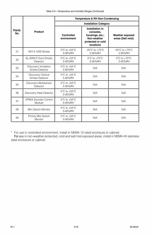
95-8533D-1016.1
Table D-2—Temperature and Humidity Ranges (Continued)
* For use in controlled environment, install in NeMA 12 rated enclosure or cabinet. For use in non-weather protected, cold and salt mist exposed areas, install in NeMA 4X stainless steel enclosure or cabinet.
Equip. No.
Product
Temperature & RH Non-Condensing
Installation Category
Controlled environment
Installation in consoles,
housings, etc.; Non-weather
protected or cold locations
Weather exposed areas (Salt mist)
31 Ast-4-1030 strobe 0°C to +55°C 5-95%rH
-25°C to +70°C 5-95%rH
-25°C to +70°C 5-95%rH
32 sl-2000-P Duct smoke Detector
0°C to +55°C 5-95%rH
0°C to +70°C 5-95%rH
0°C to +70°C 5-95%rH
33 Discovery Ionization smoke Detector
5°C to +55°C 5-95%rH N/A N/A
34 Discovery Optical smoke Detector
5°C to +55°C 5-95%rH N/A N/A
35 Discovery Multisensor Detector
5°C to +55°C 5-95%rH N/A N/A
36 Discovery Heat Detector 5°C to +55°C 5-95%rH N/A N/A
37 XP95A sounder Control Module
5°C to +55°C 5-95%rH N/A N/A
38 Mini switch Monitor 5°C to +55°C 5-95%rH N/A N/A
39 Priority Mini switch Monitor
5°C to +55°C 5-95%rH N/A N/A
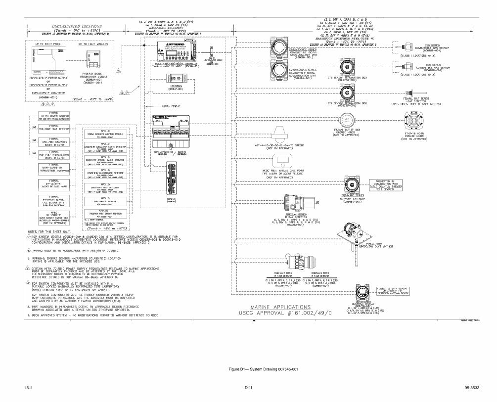
D-11 95-853316.1
Figure D1— System Drawing 007545-001
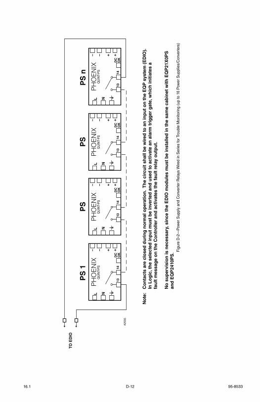
D-12 95-853316.1
TO E
DIO
L N
– – ++
DC
OK
1314
PS
nPH
OEN
IXQ
UIN
T-P
SL N
– – ++
DC
OK
1314
PS
1
PHO
ENIX
QU
INT-
PS
L N
– – ++
DC
OK
1314
PS
PHO
ENIX
QU
INT-
PS
L N
– – ++
DC
OK
1314
PS
PHO
ENIX
QU
INT-
PS
A25
55
No
te:
Co
nta
cts
are
clo
sed
du
rin
g n
orm
al o
per
atio
n.
Th
e ci
rcu
it s
hal
l be
wir
ed to
an
inp
ut
on
th
e E
QP
sys
tem
(E
DIO
).
In
Lo
gic
, th
e se
lect
ed in
pu
t m
ust
be
inve
rted
an
d u
sed
to a
ctiv
ate
an a
larm
tri
gg
er g
ate,
wh
ich
init
iate
s a
fa
ult
mes
sag
e o
n t
he
Co
ntr
olle
r an
d a
ctiv
ates
th
e fa
ult
rel
ay o
utp
ut.
N
o s
up
ervi
sio
n is
nec
essa
ry, s
ince
th
e E
DIO
mo
du
les
mu
st b
e in
stal
led
in t
he
sam
e ca
bin
et w
ith
EQ
P21
X0P
S
and
EQ
P24
10P
S. Fi
gure
D-2
—P
ower
Sup
ply
and
Con
vert
er R
elay
s W
ired
in S
erie
s fo
r Tro
uble
Mon
itorin
g (u
p to
16
Pow
er S
uppl
ies/
Con
vert
ers)

95-8533E-116.1
AppenDIX e CE MARK
EMC DIRECTIVE 2004/108/EC DETAILS
the eagle Quantum Premier Fire and gas Detection/releasing system was tested and found to be compliant with eN61000-6-2, eN61000-6-4, eN50130-4, and eN50270. the following considerations must be given for installation of the eagle Quantum Premier system.• For shielded cable installed in conduit, attach the wire shields to the “shield” connections on
the terminal blocks, or to the earth ground on the case.• For installations without conduit, use double shielded cable. terminate the outer shield to
the earth ground on the case. terminate the inner shield to the “shield” connection on the terminal blocks.
ADDITIONAL DIRECTIVES
• AteX Directive: 94/9/eC refer to Appendix C for details.• low voltage Directive: 2006/95/eC• Weee Directive: 2002/96/eC

F-1 95-853316.1
AppenDIX FROCKER SWITCH TABLE
Node Rocker Switch Address 1 2 3 4 5 6 7 8
1 X O O O O O O O 2 O X O O O O O O 3 X X O O O O O O 4 O O X O O O O O 5 X O X O O O O O 6 O X X O O O O O 7 X X X O O O O O 8 O O O X O O O O 9 X O O X O O O O 10 O X O X O O O O
11 X X O X O O O O 12 O O X X O O O O 13 X O X X O O O O 14 O X X X O O O O 15 X X X X O O O O 16 O O O O X O O O 17 X O O O X O O O 18 O X O O X O O O 19 X X O O X O O O 20 O O X O X O O O
21 X O X O X O O O 22 O X X O X O O O 23 X X X O X O O O 24 O O O X X O O O 25 X O O X X O O O 26 O X O X X O O O 27 X X O X X O O O 28 O O X X X O O O 29 X O X X X O O O 30 O X X X X O O O
31 X X X X X O O O 32 O O O O O X O O 33 X O O O O X O O 34 O X O O O X O O 35 X X O O O X O O 36 O O X O O X O O 37 X O X O O X O O 38 O X X O O X O O 39 X X X O O X O O 40 O O O X O X O O
41 X O O X O X O O 42 O X O X O X O O 43 X X O X O X O O 44 O O X X O X O O 45 X O X X O X O O 46 O X X X O X O O 47 X X X X O X O O 48 O O O O X X O O 49 X O O O X X O O 50 O X O O X X O O
51 X X O O X X O O 52 O O X O X X O O 53 X O X O X X O O 54 O X X O X X O O 55 X X X O X X O O 56 O O O X X X O O 57 X O O X X X O O 58 O X O X X X O O 59 X X O X X X O O 60 O O X X X X O O
Node Rocker Switch Address 1 2 3 4 5 6 7 8
61 X O X X X X O O 62 O X X X X X O O 63 X X X X X X O O 64 O O O O O O X O 65 X O O O O O X O 66 O X O O O O X O 67 X X O O O O X O 68 O O X O O O X O 69 X O X O O O X O 70 O X X O O O X O
71 X X X O O O X O 72 O O O X O O X O 73 X O O X O O X O 74 O X O X O O X O 75 X X O X O O X O 76 O O X X O O X O 77 X O X X O O X O 78 O X X X O O X O 79 X X X X O O X O 80 O O O O X O X O
81 X O O O X O X O 82 O X O O X O X O 83 X X O O X O X O 84 O O X O X O X O 85 X O X O X O X O 86 O X X O X O X O 87 X X X O X O X O 88 O O O X X O X O 89 X O O X X O X O 90 O X O X X O X O
91 X X O X X O X O 92 O O X X X O X O 93 X O X X X O X O 94 O X X X X O X O 95 X X X X X O X O 96 O O O O O X X O 97 X O O O O X X O 98 O X O O O X X O 99 X X O O O X X O 100 O O X O O X X O
101 X O X O O X X O 102 O X X O O X X O 103 X X X O O X X O 104 O O O X O X X O 105 X O O X O X X O 106 O X O X O X X O 107 X X O X O X X O 108 O O X X O X X O 109 X O X X O X X O 110 O X X X O X X O
111 X X X X O X X O 112 O O O O X X X O 113 X O O O X X X O 114 O X O O X X X O 115 X X O O X X X O 116 O O X O X X X O 117 X O X O X X X O 118 O X X O X X X O 119 X X X O X X X O 120 O O O X X X X O

95-8533F-216.1
Rocker Switch Table
Node Rocker Switch Address 1 2 3 4 5 6 7 8
121 X O O X X X X O 122 O X O X X X X O 123 X X O X X X X O 124 O O X X X X X O 125 X O X X X X X O 126 O X X X X X X O 127 X X X X X X X O 128 O O O O O O O X 129 X O O O O O O X 130 O X O O O O O X
131 X X O O O O O X 132 O O X O O O O X 133 X O X O O O O X 134 O X X O O O O X 135 X X X O O O O X 136 O O O X O O O X 137 X O O X O O O X 138 O X O X O O O X 139 X X O X O O O X 140 O O X X O O O X
141 X O X X O O O X 142 O X X X O O O X 143 X X X X O O O X 144 O O O O X O O X 145 X O O O X O O X 146 O X O O X O O X 147 X X O O X O O X 148 O O X O X O O X 149 X O X O X O O X 150 O X X O X O O X
151 X X X O X O O X 152 O O O X X O O X 153 X O O X X O O X 154 O X O X X O O X 155 X X O X X O O X 156 O O X X X O O X 157 X O X X X O O X 158 O X X X X O O X 159 X X X X X O O X 160 O O O O O X O X 161 X O O O O X O X 162 O X O O O X O X 163 X X O O O X O X 164 O O X O O X O X 165 X O X O O X O X 166 O X X O O X O X 167 X X X O O X O X 168 O O O X O X O X 169 X O O X O X O X 170 O X O X O X O X
171 X X O X O X O X 172 O O X X O X O X 173 X O X X O X O X 174 O X X X O X O X 175 X X X X O X O X 176 O O O O X X O X 177 X O O O X X O X 178 O X O O X X O X 179 X X O O X X O X 180 O O X O X X O X
181 X O X O X X O X 182 O X X O X X O X 183 X X X O X X O X 184 O O O X X X O X 185 X O O X X X O X 186 O X O X X X O X 187 X X O X X X O X 188 O O X X X X O X 189 X O X X X X O X 190 O X X X X X O X
Node Rocker Switch Address 1 2 3 4 5 6 7 8
191 X X X X X X O X 192 O O O O O O X X 193 X O O O O O X X 194 O X O O O O X X 195 X X O O O O X X 196 O O X O O O X X 197 X O X O O O X X 198 O X X O O O X X 199 X X X O O O X X 200 O O O X O O X X
201 X O O X O O X X 202 O X O X O O X X 203 X X O X O O X X 204 O O X X O O X X 205 X O X X O O X X 206 O X X X O O X X 207 X X X X O O X X 208 O O O O X O X X 209 X O O O X O X X 210 O X O O X O X X
211 X X O O X O X X 212 O O X O X O X X 213 X O X O X O X X 214 O X X O X O X X 215 X X X O X O X X 216 O O O X X O X X 217 X O O X X O X X 218 O X O X X O X X 219 X X O X X O X X 220 O O X X X O X X
221 X O X X X O X X 222 O X X X X O X X 223 X X X X X O X X 224 O O O O O X X X 225 X O O O O X X X 226 O X O O O X X X 227 X X O O O X X X 228 O O X O O X X X 229 X O X O O X X X 230 O X X O O X X X
231 X X X O O X X X 232 O O O X O X X X 233 X O O X O X X X 234 O X O X O X X X 235 X X O X O X X X 236 O O X X O X X X 237 X O X X O X X X 238 O X X X O X X X 239 X X X X O X X X 240 O O O O X X X X
241 X O O O X X X X 242 O X O O X X X X 243 X X O O X X X X 244 O O X O X X X X 245 X O X O X X X X 246 O X X O X X X X 247 X X X O X X X X 248 O O O X X X X X 249 X O O X X X X X 250 O X O X X X X X
O = OPeN / OFF
X = ClOseD / ON
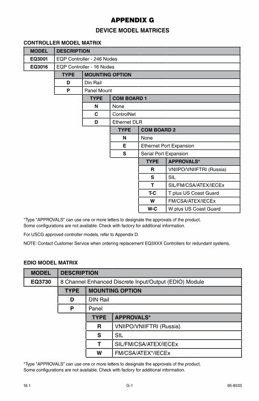
G-1 95-853316.1
AppenDIX g DEVICE MODEL MATRICES
MODEL DESCRIPTION
EQ3001 EQP Controller - 246 Nodes
EQ3016 EQP Controller - 16 Nodes
TYPE MOUNTING OPTION
D Din Rail
P Panel Mount
TYPE COM BOARD 1
N None
C ControlNet
D Ethernet DLR
TYPE COM BOARD 2
N None
E Ethernet Port Expansion
S Serial Port Expansion
TYPE APPROVALS*
R VNIIPO/VNIIFTRI (Russia)
S SIL
T SIL/FM/CSA/ATEX/IECEx
T-C T plus US Coast Guard
W FM/CSA/ATEX/IECEx
W-C W plus US Coast Guard
*Type "APPROVALS" can use one or more letters to designate the approvals of the product.Some configurations are not available. Check with factory for additional information.
For USCG approved controller models, refer to Appendix D.
NOTE: Contact Customer Service when ordering replacement EQ3XXX Controllers for redundant systems.
CONTROLLER MODEL MATRIX
MODEL DESCRIPTION
EQ3730 8 Channel Enhanced Discrete Input/Output (EDIO) Module
TYPE MOUNTING OPTION
D DIN Rail
P Panel
TYPE APPROVALS*
R VNIIPO/VNIIFTRI (Russia)
S SIL
T SIL/FM/CSA/ATEX/IECEx
W FM/CSA/ATEX*/IECEx
*Type "APPROVALS" can use one or more letters to designate the approvals of the product.Some configurations are not available. Check with factory for additional information.
EDIO MODEL MATRIX
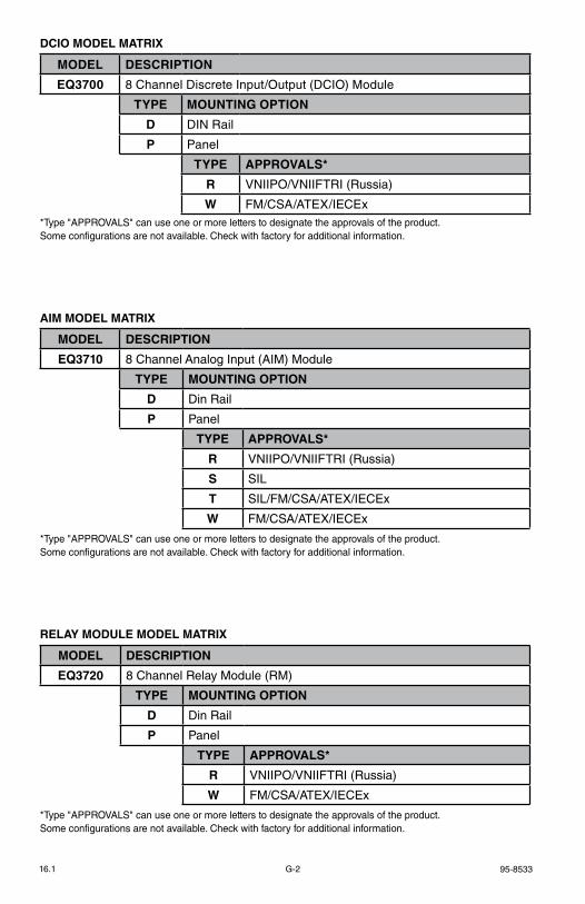
95-8533G-216.1
MODEL DESCRIPTION
EQ3700 8 Channel Discrete Input/Output (DCIO) Module
TYPE MOUNTING OPTION
D DIN Rail
P Panel
TYPE APPROVALS*
R VNIIPO/VNIIFTRI (Russia)
W FM/CSA/ATEX/IECEx*Type "APPROVALS" can use one or more letters to designate the approvals of the product.Some configurations are not available. Check with factory for additional information.
DCIO MODEL MATRIX
MODEL DESCRIPTION
EQ3710 8 Channel Analog Input (AIM) Module
TYPE MOUNTING OPTION
D Din Rail
P Panel
TYPE APPROVALS*
R VNIIPO/VNIIFTRI (Russia)
S SIL
T SIL/FM/CSA/ATEX/IECEx
W FM/CSA/ATEX/IECEx
*Type "APPROVALS" can use one or more letters to designate the approvals of the product.Some configurations are not available. Check with factory for additional information.
AIM MODEL MATRIX
MODEL DESCRIPTION
EQ3720 8 Channel Relay Module (RM)
TYPE MOUNTING OPTION
D Din Rail
P Panel
TYPE APPROVALS*
R VNIIPO/VNIIFTRI (Russia)
W FM/CSA/ATEX/IECEx
*Type "APPROVALS" can use one or more letters to designate the approvals of the product.Some configurations are not available. Check with factory for additional information.
RELAY MODULE MODEL MATRIX

95-8533
X3301 MultispectrumIR Flame Detector
PointWatch Eclipse® IR Combustible Gas Detector
FlexVu® Universal Display with GT3000 Toxic Gas Detector
Eagle Quantum Premier®
Safety SystemFlexSonic® Acoustic
Leak Detector
Corporate Office6901 West 110th StreetMinneapolis, MN 55438 USA
www.det-tronics.com
All trademarks are the property of their respective owners. © 2014 Detector Electronics Corporation. All rights reserved.
Det-Tronics manufacturing system is certified to ISO 9001— the world’s most recognized quality management standard.
Phone: 952.946.6491 Toll-free: 800.765.3473Fax: [email protected]