Embed Size (px)
Citation preview
Document No: D72539-L20-1
I N S T R U C T I O N S F O R C O N TI N U E D A I R W O R T H I N E S S
FOR
Royal Air, Inc.
IS&S AIR DATA SYSTEM 9K-04590-5
&
ROSEMOUNT 856NA1&2 PITOT/STATIC PROBES
WHEN INSTALLED IN: LEARJET
MODELS: 24 Series / 25 Series / 28 / 35/35A & 36/36A
REGISTRATION NO. ______________ SERIAL NO._____________________
This document must be attached to the Airplane Maintenance Manuals when the aircraft is modified in accordance with STC No. ST01904CH by the installation of an IS&S Air Data System and Rosemount Pitot/Static Probes in accordance with Royal Air Top Drawing No: RACB72539 Rev.11 or later. This document is further required to maintain RVSM Compliance in accordance with STC ST02016CH . In addition, an aircraft logbook entry referring to this document must be made to insure that maintenance personnel have reference to this inspection requirement. The information in this document supplements the basic airplane maintenance manual only where covered in the items contained herein. For Limitations and Procedures not contained in this supplement, consult the basic Airplane Maintenance Manuals.
Doc. No. D72539-L20-1 Rev. 7 12/15/08 Cover
Royal Air, Inc Instructions for Continued Airworthiness 2141 Airport Rd Learjet Models 24/25/28/35/35A/36/36A Waterford, MI 48327 Revised Pitot-Statics and Altimetry
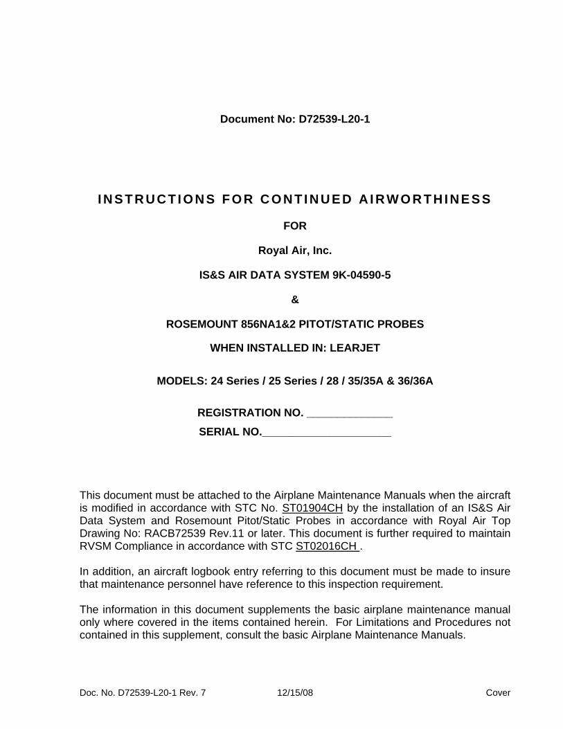
LOG OF REVISIONS
Revision
Date Affected Pages
Description of Revision
IR 09/24/03 All Initial Release
1 12/05/03 All Reformat + References & Ground Test Procedures added
2 07/15/04 All Added procedures and equipment description for RVSM compliance.
3 12/28/04 All Added references to Models 35/36 on all pages. Added reference to FC-200 Autopilot on Page 1
4 04/15/05 All Added reference to Model 28 on all pages.
5 08/10/05 All Added references to Models 35/36 in the header on all pages
6 04/17/06 All Added reference to optional 9D-80170-3 ADDU Installation
7 12/15/08 All Added reference to additional Configuration Module Part Numbers & Installation Configurations & changed Flight Test altitudes in appendix A
Doc. No. D72539-L20-1 Rev. 7 12/15/08 LOR Page 1
Royal Air, Inc Instructions for Continued Airworthiness 2141 Airport Rd Learjet Models 24/25/28/35/35A/36/36A Waterford, MI 48327 Revised Pitot-Statics and Altimetry
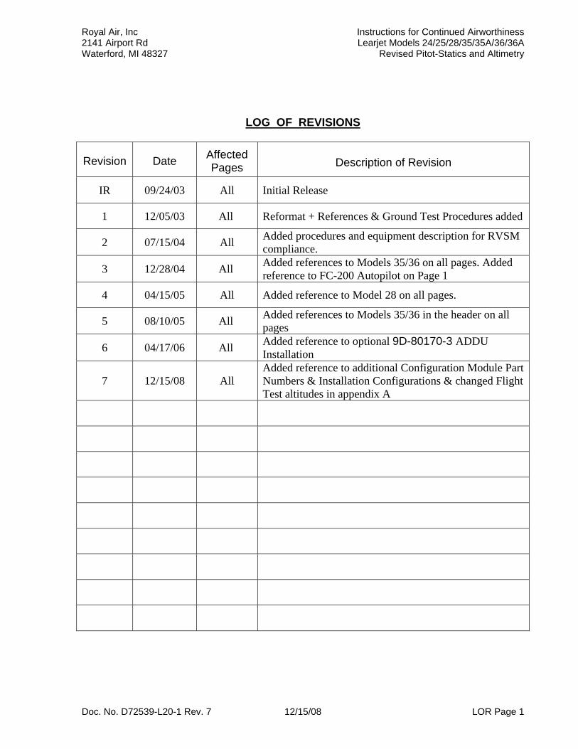
LIST OF EFFECTIVE PAGES
Page RevisionCover 7 LOR 1 7 LEP 1 7 TOC 1 7
1 7 2 7 3 7 4 7 5 7 6 7 7 7 8 7 9 7 10 7 11 7 12 7 13 7 14 7 15 7 16 7 17 7
Doc. No. D72539-L20-1 Rev. 7 12/15/08 LEP Page 1
Royal Air, Inc Instructions for Continued Airworthiness 2141 Airport Rd Learjet Models 24/25/28/35/35A/36/36A Waterford, MI 48327 Revised Pitot-Statics and Altimetry
TABLE OF CONTENTS Log of Revisions .......................................................................................................LOR 1 List of Effective Pages............................................................................................... LEP 1 Table of Contents .................................................................................................... TOC 1 SECTION 1: INTRODUCTION .........................................................................................1 A. Description of the System .........................................................................................1 B. List of Applicable Publications ..................................................................................2 C. Purpose ....................................................................................................................2 D. Revision Distribution Procedures ..............................................................................2 SECTION 2: INSPECTION REQUIREMENTS AND OVERHAUL SCHEDULE ...............3 A. Scheduled Maintenance Interval................................................................................3 SECTION 3: AIRWORTHINESS LIMITATION INFORMATION .......................................4 A. Required Inspections ................................................................................................4 SECTION 4: INSPECTION AND MAINTENANCE PROCEDURES ...............................4 A. Equipment Location ..................................................................................................4 B. 9B-81040-30 IS&S Analog Interface Unit (AIU) Removal and Installation.................4 C. 9D-80130-15 IS&S or 9D-80170-3 (ADDU) Removal and Installation ....................5 D. RACB72539-6 Accessory / CB (ACB) Panel Removal and Installation ....................5 E. Standby Altimeter Removal and Installation ..............................................................5 F. Rosemount Pitot / Static Probe Removal and Installation .........................................6 G. Pitot Heat Power Consumption Test .........................................................................6 H. Pitot & Static System Leakage Test ..........................................................................6 I. Pitot Tube Pressure Leakage Test..............................................................................7 J. Autopilot Altitude Hold Test .......................................................................................7 K. AIU FAIL Warning Light Test ....................................................................................7 L. Pitot / Static Probe Drain Hole Inspection ..................................................................7 M. Pitot / Static Probe and Area Surrounding Probe Inspection ....................................8 N. Ground Test Procedure ADDU ................................................................................ 9 O. Ground Test Procedure ACB Panel ........................................................................10 P. Wiring Harness Inspection .......................................................................................10 Q. In Flight Autopilot Altitude Hold Check ....................................................................10 Figure 1 – Inspection Criteria for Static Ports ...............................................................11 Figure 2 – Pitot / Static Probe Lip Flatness ..................................................................11 Figure 3 – Pitot / Static Probe Lip Outward Flare ...................................................... 12 Figure 4 – Indentation of Pitot / Static Probe Opening ................................................ 12 Figure 5 – Nicks in Pitot / Static Probe Tip ................................................................. 13 SECTION 5: TROUBLESHOOTING ..............................................................................14 A. Difference Betweem Pilot’s and Copilot’s Altimeters ..............................................14 B. Non Responsive altitude Information in Flight ........................................................14 C. Non Responsive Airspeed Information in Flight ......................................................14 D. Autopilot Altitude Hold Inoperative ..........................................................................14 E. “AIU FAIL” Warning Light Inoperative .....................................................................14 Pitot / Static System Block Diagram ............................................................................15 IS&S Air Data System Block Diagram .........................................................................16 Appendix A: Flight Test Procedure for Autopilot Altitude Hold Test ....................17
Doc. No. D72539-L20-1 Rev. 7 12/15/08 TOC Page 1
Royal Air, Inc Instructions for Continued Airworthiness 2141 Airport Rd Learjet Models 24/25/28/35/35A/36/36A Waterford, MI 48327 Revised Pitot-Statics and Altimetry
SECTION 1: INTRODUCTION A. Description of the System 1. The system described herein is the installation of new Rosemount Pitot / Static
Probes along with the IS&S Air Data System which is comprised of the following components:.
• 9B-81040-30 IS&S Analog Interface Unit (Not required with all configurations)* • 9D-80130-15 or 9D-80170-3 IS&S Air Data Display Unit (ADDU) (2 ea.)* • 9B-03508-114 Configuration Module for 9D-80130-15 (RVSM Compliant) (2 ea.) • 9B-06017-12 or 41 Config. Module for 9D-80170-3 (RVSM Compliant) (2 ea.) * • RACB72539-6 Accessory / CB Panel • Pressure type (non electric) Standby Altimeter • 856NA1 Rosemount Pitot/Static Probe, Left • 856NA2 Rosemount Pitot/static Probe, Right
2. These components are interfaced with aircraft’s:
• 28VDC power • FC-110 or FC-200 Autopilot • 115VAC 400hz Inverter (26VAC via transformer in autopilot system) • Pitot / Static System
3. The system is comprised of 7 major components.
a. 9B-81040-30 IS&S Analog Interface Unit (AIU) (may not be in all installations) b. Pilot’s 9D-80130-15 IS&S Air Data Display Unit (ADDU) with 9B-03508-114
Configuration Module * c. Copilot’s 9D-80130-15 IS&S Air Data Display Unit (ADDU) with 9B-03508-114
Configuration Module * d. RACB72539-6 Accessory / CB Panel e. Pressure type (non electric) Standby Altimeter f. 856NA1 Rosemount Pitot/Static Probe, Left g. 856NA2 Rosemount Pitot/static Probe, Right * Pilot's and Copilot's Air Data Display Units may optionally be 9D-80170-3 with 9B-
06017-12 or 9B-06017-41 Configuration Modules depending on Installation Configuration. See Approved Flight manual Supplement for Installation Configuration information.
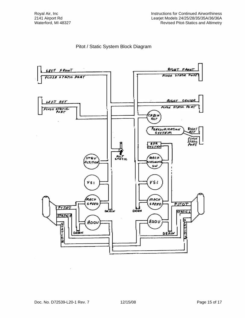
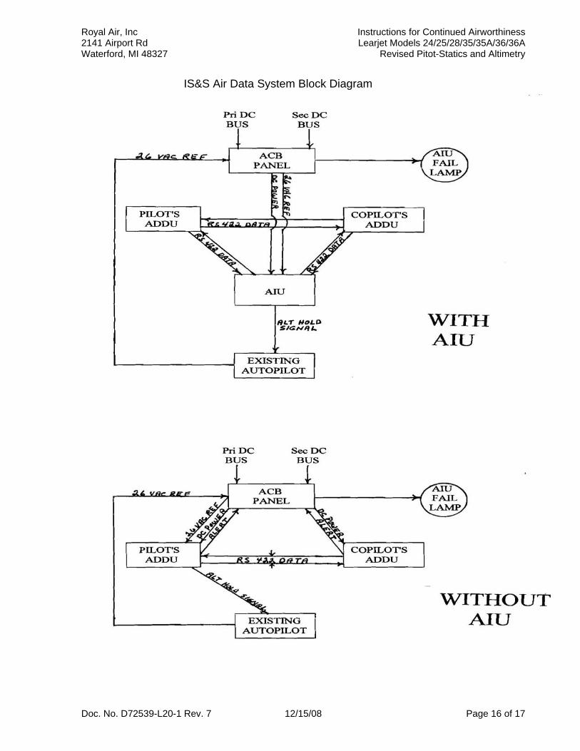
Refer to pages 15 and 16 for block diagrams of the RACB72539 system as it is installed per this STC.
Doc. No. D72539-L20-1 Rev. 7 12/15/08 Page 1 of 17
Royal Air, Inc Instructions for Continued Airworthiness 2141 Airport Rd Learjet Models 24/25/28/35/35A/36/36A Waterford, MI 48327 Revised Pitot-Statics and Altimetry
B. List of Applicable Publications: The following documents provide operation and servicing information: 1. FAA Approved Airplane Flight Manual Supplement. 2. Top Drawing: RACB72539 Rev. 11 or later
-1 Pitot/Static Probe Installation -2 Fillers and Doublers -3 AIU Mounting Tray Installation -4 Wiring Harness -5 Harness Routing -6 Accessory / CB Panel -7 standby Altimeter Installation
3. Royal Air Procedural Specifications: RAPS-L20
-1 Pitot/Static Probe Install -2 Copilot’s ADDU Installation -3 AIU Mounting Tray Installation -4 Rosemount / IS&S System Installation
C. Purpose: 1. This document will provide Instructions for Continued Airworthiness required by
14 Code of Federal Regulations (CFR) Section 25.1529 (Appendix H).
D. Revision Distribution Procedures: 1. Royal Air, Inc. will maintain a file containing the model and serial number, date of
modification, and the owners names and addresses of all aircraft modified under this STC.
2. If, for any reason, this document is revised Royal Air, Inc. will promptly mail (using
the U.S. Postal Service first class mail) a copy of the revised Instructions for Continued Airworthiness (ICA).
3. Royal Air, Inc. will maintain a Revision Distribution File which will contain the
following: a. Aircraft model & serial number b. Date of modification c. Aircraft owners name and address d. ICA Revision Number e. Date revised ICA mailed to aircraft owner f. Name of Royal Air employee sending the revision
Doc. No. D72539-L20-1 Rev. 7 12/15/08 Page 2 of 17
Royal Air, Inc Instructions for Continued Airworthiness 2141 Airport Rd Learjet Models 24/25/28/35/35A/36/36A Waterford, MI 48327 Revised Pitot-Statics and Altimetry
SECTION 2: INSPECTION REQUIREMENTS AND OVERHAUL SCHEDULE
A. Scheduled Maintenance Interval
1. To coincide with the Nose Inspection during the 300 hr. Inspection, or Phase A2 inspection, or currently FAA approved Operator’s Maintenance program, Perform the Pitot / Static Probe Drain hole inspection – Follow Inspection procedures in Section 4L of this document. 2. To coincide with the Nose Inspection during the 600 hr. Inspection, or phase B2 Inspection, or currently FAA approved Operator’s Maintenance program, Inspect the Fuselage area surrounding the (Rosemount Pitot/Static) probes. – Follow the inspection procedures in Section 4M1 of this document. 3. To coincide with the Nose Inspection during the 600 hr. Inspection, or phase B2 Inspection, or currently FAA approved Operator’s Maintenance program, Inspect the Rosemount Pitot / Static Probes. – Follow the inspection procedures in Section 4M2 of this document. 4. To coincide with the Cockpit Inspection during the 600 hr. Inspection, or phase B2 Inspection, or currently FAA approved Operator’s Maintenance program, test the Air data display units. – Follow the test procedures in Section 4N of this document. 5. To coincide with the Cockpit Inspection during the 1200 Hr. Inspection, C2 Inspection, or FAA approved Operator’s Maintenance program, The wiring harness associated with the Air Data System must be visually inspected in accordance with Section 4P herein
6. Every 24 months an In Flight Autopilot Altitude Hold Check shall be accomplished. Follow the procedure in Section 4Q herein. 7. Every 24 Months The IS&S Air Data System and Rosemount Pitot / Static Probes are subject to the Altimeter and Static System Test and Inspections of 14 CFR Part 43, Appendix E as required by 14 CFR 91.411.
Doc. No. D72539-L20-1 Rev. 7 12/15/08 Page 3 of 17
Royal Air, Inc Instructions for Continued Airworthiness 2141 Airport Rd Learjet Models 24/25/28/35/35A/36/36A Waterford, MI 48327 Revised Pitot-Statics and Altimetry
SECTION 3: AIRWORTHINESS LIMITATIONS This document must be attached to the Airplane Maintenance Manuals. The information contained herein supplements the basic Maintenance Manuals only in those areas listed, when the aircraft is modified in accordance with Royal Air Top Drawing RACB72539 as described by the STC. For limitations and procedures not contained in this supplement, consult the basic Maintenance Manuals. The Airworthiness Limitations Section is FAA approved and specifies inspections and other maintenance required and under §§ 43.16 and 91.403 of the Federal Aviation Regulations (FAR) unless an alternative program has been FAA approved. A. REQUIRED INSPECTIONS There are no airworthiness limitations associated with this type design change. SECTION 4 INSPECTION & MAINTENANCE PROCEDURES
A. Equipment Location 1. For location of items not listed below refer to system wiring diagrams, Aircraft Weight and Balance / Equipment list for locations of equipment installed by this STC.
B. 9B-81040-30 IS&S Analog Interface Unit (AIU) Removal and Installation 1. Location – Under Copilot’s seat (if installed). 2. Removal:
a. Remove power to the system. b. Remove connectors P5003 and P5004. c. Loosen the securing screw on the mounting tray and remove the unit.
3. Installation:
a. Place the AIU in the mounting tray and hand tighten the securing screw. b. Install connectors P5003 and P5004. c. Power up the system and verify that the AIU Fail lamp is NOT illuminated then,
Referring to the Altitude Hold test procedures in Section 4 Paragraph J, check for proper operation.
Doc. No. D72539-L20-1 Rev. 7 12/15/08 Page 4 of 17
Royal Air, Inc Instructions for Continued Airworthiness 2141 Airport Rd Learjet Models 24/25/28/35/35A/36/36A Waterford, MI 48327 Revised Pitot-Statics and Altimetry
C. 9D-80130-15 or 9D-80170-3 Air Data Display Unit (ADDU) Removal and Installation
1. Location – Instrument Panel (Pilot’s or Copilot’s) 2. Removal:
a. Remove power to the system. b. Disconnect the Pitot and Static lines, cap lines to prevent contamination. c. Disconnect the connector and remove the mounting screws and remove ADDU.
3. Installation:
a. Verify that a 9B-03508-114 Configuration module is plugged into J2 on the back of the 9D80130-15 or a 9B-06017-12 is plugged into the 9D-80170-3. b. Mount ADDU and secure with mounting screws. c. Connect the primary connector and the Pitot Static lines. d. Perform Pitot & Static System Leakage Test per Section 4 Paragraph H. e. Referring to the ADDU ground test procedures in Section 4 Paragraph N, power up system and check for proper operation.
D. RACB72539-6 Accessory / CB (ACB) Panel Removal and Installation 1. Location – Center Pedestal 2. Removal:
a. Remove power from the system. b. Loosen the 4 Dzus fasteners and lift out the ACB Panel. c. Disconnect the 2 connectors and remove the unit.
3. Installation:
a. Connect the 2 connectors. b. Place unit in position and secure the 4 dzus fasteners. c. Referring to the ACB Panel ground test procedures in Section 4 Paragraph O, power up the system and check for proper operation.
E. Standby Altimeter Removal and installation 1. Location – Instrument panel near emergency gyro. 2. Removal:
a. Remove standby altimeter mounting panel by loosening the 4 dzus fasteners. b. Remove static line from altimeter and cap to prevent contamination. c. Disconnect and remove post light (if installed) from upper right corner of the altimeter. d. Remove mounting screws and remove altimeter from panel.
3. Installation:
a. Install standby altimeter in panel with mounting screws. b. Install and connect post light in upper right corner if altimeter c. Remove cap and connect static line. d. Perform Leak check of Flush Mounted Static Ports per FAR Part 43 Appendix E.
Doc. No. D72539-L20-1 Rev. 7 12/15/08 Page 5 of 17
Royal Air, Inc Instructions for Continued Airworthiness 2141 Airport Rd Learjet Models 24/25/28/35/35A/36/36A Waterford, MI 48327 Revised Pitot-Statics and Altimetry
F. Rosemount Pitot / Static Probe Removal and Installation 1. Location – one probe on each side of aircraft between frames 4 and 5. 2. Removal:
a. Remove nose compartment access doors and remove equipment as required to gain access to the pitot-static tube. b. Disconnect electrical connector from pitot-static tube. c. Loosen and disconnect pitot and static lines from pitot-static tube – cap lines. d. Remove attaching parts and pitot-static tube from aircraft. Clean old fay sealant from base mount. e. Verify that the eccentric nut is safety wired. If not refer to Royal Air Procedural Specification for probe alignment and eccentric nut safety wire procedures.
3. Installation:
a. Apply fay seal to surface of base mount. Position pitot-static tube on base mount assuring that probe pin is fully engaged in eccentric nut and install attaching parts. Torque nuts 30 to 40 inch pounds. b. Remove caps from pitot and static lines and connect lines to pitot-static tube. c. Connect electrical connector to pitot-static tube. d. Perform Pitot & Static System leakage check per Section 4 Paragraph H. e. Check pitot-static tube for proper heating as follows:
1. Set applicable pitot heat switch on. 2. Check that pitot-static probe starts to warm up. 3. Set applicable pitot heat switch off
f. Install previously removed equipment. g. Install nose compartment access doors.
G. Pitot heat power consumption Test
1. If pitot heat does not heat properly check power consumption in still, room temperature air. After 5 minutes of operation, check amperage. The amperage shall be 6.3 to 7.0 amperes.
H. Pitot & Static System leakage Test 1. Connect a Barsfield DPS-450 (or equivalent) Air Data Test Set to the
Rosemount Pitot / Static Probes using PSS61587-3-4-4 Probe Adapters. 2. At field elevation increase airspeed to 300 knots. (do not exceed 20 kts/sec)
Verify that leakage rate is less than 5 knots in 5 seconds. Return airspeed to zero knots.
3. Increase altitude to 30,000 feet. (do not exceed 6,000 feet per minute) Verify that leakage does not exceed 100 feet in one minute. Note: 100 feet is the maximum allowable leakage – experience has shown that less than 35 feet leakage is the average.
4. Repair any leakages noted – check all fittings, tubing, hoses, and drains in the pitot / static system. If a pitot system leakage can not be found perform the Pitot Tube pressure leakage test outlined in paragraph I below.
Doc. No. D72539-L20-1 Rev. 7 12/15/08 Page 6 of 17
Royal Air, Inc Instructions for Continued Airworthiness 2141 Airport Rd Learjet Models 24/25/28/35/35A/36/36A Waterford, MI 48327 Revised Pitot-Statics and Altimetry
I. Pitot Tube Pressure Leakage Test 1. If excessive leakage is noted during a pitot system leakage check, check pitot tube pressure leakage. Remove pitot tube. Seal all pressure openings and drain holes in pitot tube. Apply 80 in. Hg (39.2 psi) and seal off pressure source. Internal pressure drop shall not excede 0.40 in Hg (0.2 psi) in one minute.
J. Autopilot Altitude Hold Test 1. Connect a Barsfield DPS-450 (or equivalent) Air Data Test Set to the
Rosemount Pitot / Static Probes using PSS61587-3-4-4 Probe Adapters. 2. Connect a power cart to the aircraft then turn on battery switch and the primary and secondary inverter switches. 3. Increase test set altitude to 3000 feet. 4. Turn on and engage autopilot. 5. Select 3000 feet on either Pilot’s or Copilot’s ADDU & BARO set to 29.92”. 6. Engage autopilot altitude hold. 7. Increase test set altitude to 3020 feet. Verify that the control yoke moves forward. 8. decrease test set altitude to 2980 feet. Verify that the control yoke moves aft.
K. “AIU FAIL” Warning Light Test
1. Connect a power cart to the aircraft then turn on battery switch and the primary and secondary inverter switches. 2. Turn on the Avionics and/or Autopilot Master switches (if any). a. Verify that the AIU FAIL lamp is NOT illuminated. 2. Activate the test switch on the ACB Panel in the center console. a. Verify that the AIU FAIL lamp illuminates. 3. Pull the 26VAC AIU circuit breaker on the ACB Panel. a. Verify that the AIU FAIL lamp illuminates. b. Re-set the 26VAC AIU circuit breaker. 4. Pull both AIU circuit breakers on the ACB Panel. a. Verify that the AIU FAIL lamp illuminates. b. Re-set both AIU circuit breakers c. Verify that the AIU FAIL lamp is NOT illuminated.
L. Pitot / Static Probe Drain Hole Inspection
1. Locate pitot drain hole on left pitot-static probe. The drain hole is located approximately 1.5 in. aft from front of head on lower surface.
2. Ensure drain hole is not clogged by shining a high intensity light through the hole while looking through the pitot head.
a. A 0.020 in. diameter brass or copper wire may be inserted into the drain hole to check for and / or dislodge any contamination. If contamination exists, disconnect pitot pressure line from head and back flush contaminate out head’s pitot opening using dry nitrogen.
3. Repeat steps 1 and 2 for the right pitot-static probe.
Doc. No. D72539-L20-1 Rev. 7 12/15/08 Page 7 of 17
Royal Air, Inc Instructions for Continued Airworthiness 2141 Airport Rd Learjet Models 24/25/28/35/35A/36/36A Waterford, MI 48327 Revised Pitot-Statics and Altimetry
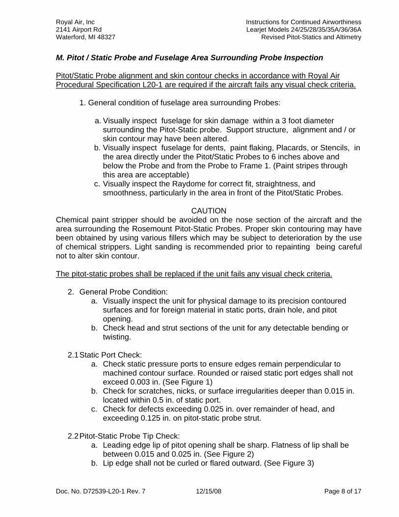
M. Pitot / Static Probe and Fuselage Area Surrounding Probe Inspection Pitot/Static Probe alignment and skin contour checks in accordance with Royal Air Procedural Specification L20-1 are required if the aircraft fails any visual check criteria.
1. General condition of fuselage area surrounding Probes: a. Visually inspect fuselage for skin damage within a 3 foot diameter
surrounding the Pitot-Static probe. Support structure, alignment and / or skin contour may have been altered.
b. Visually inspect fuselage for dents, paint flaking, Placards, or Stencils, in the area directly under the Pitot/Static Probes to 6 inches above and below the Probe and from the Probe to Frame 1. (Paint stripes through this area are acceptable)
c. Visually inspect the Raydome for correct fit, straightness, and smoothness, particularly in the area in front of the Pitot/Static Probes.
CAUTION
Chemical paint stripper should be avoided on the nose section of the aircraft and the area surrounding the Rosemount Pitot-Static Probes. Proper skin contouring may have been obtained by using various fillers which may be subject to deterioration by the use of chemical strippers. Light sanding is recommended prior to repainting being careful not to alter skin contour. The pitot-static probes shall be replaced if the unit fails any visual check criteria.
2. General Probe Condition: a. Visually inspect the unit for physical damage to its precision contoured
surfaces and for foreign material in static ports, drain hole, and pitot opening.
b. Check head and strut sections of the unit for any detectable bending or twisting.
2.1 Static Port Check:
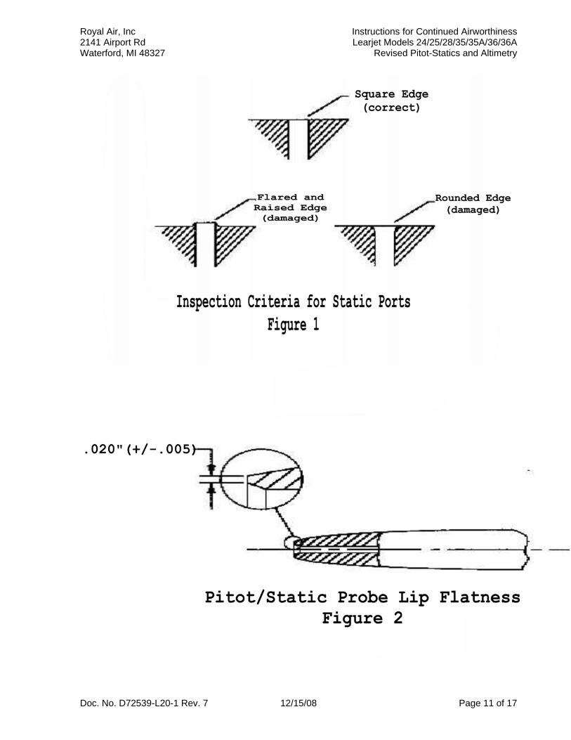
a. Check static pressure ports to ensure edges remain perpendicular to machined contour surface. Rounded or raised static port edges shall not exceed 0.003 in. (See Figure 1)
b. Check for scratches, nicks, or surface irregularities deeper than 0.015 in. located within 0.5 in. of static port.
c. Check for defects exceeding 0.025 in. over remainder of head, and exceeding 0.125 in. on pitot-static probe strut.
2.2 Pitot-Static Probe Tip Check:
a. Leading edge lip of pitot opening shall be sharp. Flatness of lip shall be between 0.015 and 0.025 in. (See Figure 2)
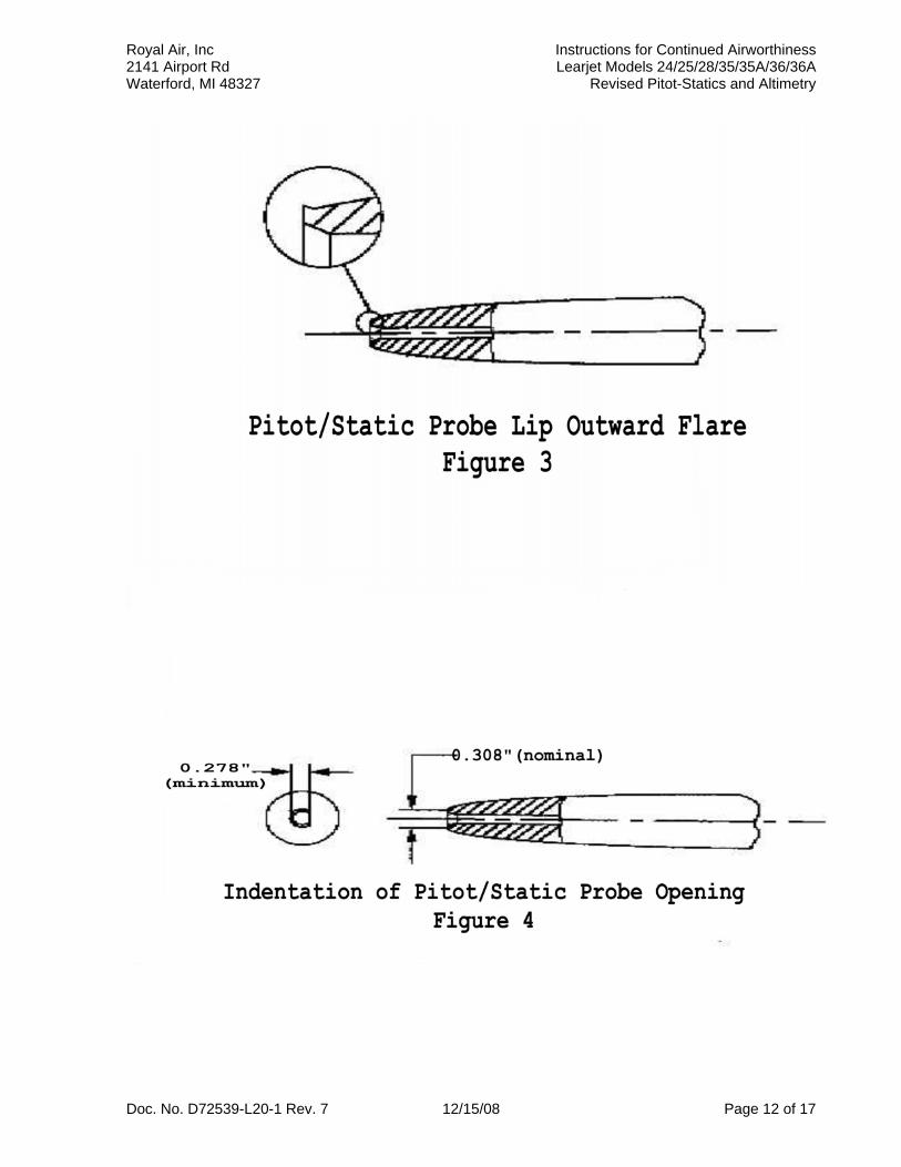
b. Lip edge shall not be curled or flared outward. (See Figure 3)
Doc. No. D72539-L20-1 Rev. 7 12/15/08 Page 8 of 17
Royal Air, Inc Instructions for Continued Airworthiness 2141 Airport Rd Learjet Models 24/25/28/35/35A/36/36A Waterford, MI 48327 Revised Pitot-Statics and Altimetry
Note: This condition can be detected by sliding a fingernail along the outer surface at tip of pitot-static barrel.
d. Indentations on lip shall not deviate more than 0.030 in. from normal tip
diameter. A dent at any location around opening shall not affect more than 20% of circumference. (See Figure 4)
Damage of this type may be repairable. Return units to Rosemount, Inc. for possible repair. Note: Small inward dents on lip which do not affect roundness of pitot opening are acceptable.
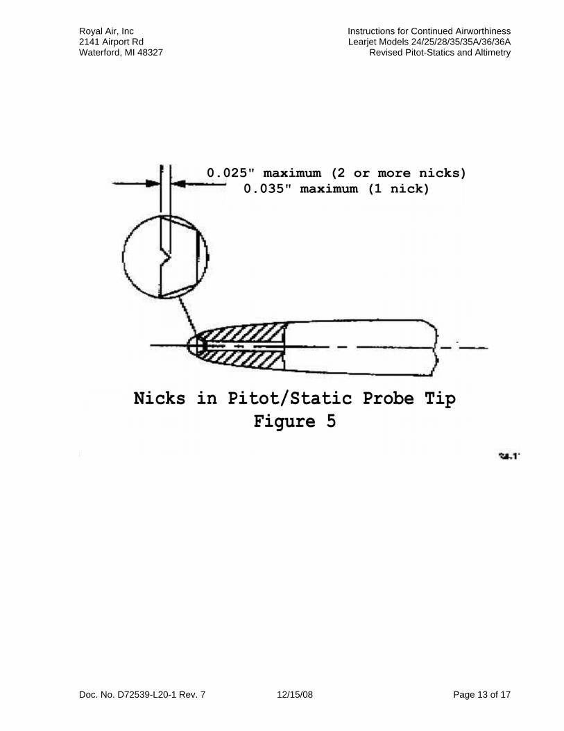
e. Leading edge lip can have small nicks or chips. (See Figure 5) There shall
not be more than one nick between 0.025 and 0.035 in. deep or any nick more than 0.035 in. deep.
f. Verify that the Correct Probes Installed. Rosemount Part number 856NA1
on the left side and 856NA2 on the right. N. Ground Test Procedure 9D-80130-15 or 9D-80170-3 Air Data Display Unit (ADDU) 1. Apply auxiliary power and turn on master switch. a. Monitor startup test sequence & verify that: 1. No error codes are present 2. Center Display shows “24.25”. 3. Lower left displays “A 105” ("A 105" not displayed on 9D-80170-3) 4. Lower right displays “1 yes” on the pilot’s side and “2 yes” on the copilot’s side. 5. All display (LCD) segments illuminate. Note: Test sequence may be repeated using the test switch on the ACB Panel. 2. On the copilot’s circuit breaker panel, pull the PRI ALT circuit breaker.
a. Verify that “PWR” flag illuminates on pilots ADDU but pilot’s and Copilot’s ADDUs still function normally. – Reset Circuit Breaker.
3. On the copilot’s circuit breaker panel, pull the SEC ALT circuit breaker.
a. Verify that “PWR” flag illuminates on copilots ADDU but pilot’s and Copilot’s ADDUs still function normally. – Reset Circuit Breaker.
4. Referring to the Flight Manual Supplement – Section II Normal Procedures: a. Verify proper operation of the BARO knob. b. Verify proper operation of the ALT SEL (altitude alerter) knob.
Doc. No. D72539-L20-1 Rev. 7 12/15/08 Page 9 of 17
Royal Air, Inc Instructions for Continued Airworthiness 2141 Airport Rd Learjet Models 24/25/28/35/35A/36/36A Waterford, MI 48327 Revised Pitot-Statics and Altimetry
O. Ground Test Procedure 72539-6 Accessory Circuit Breaker (ACB) Panel 1. Apply auxiliary power, turn on inverters, radio and autopilot masters. a. Verify that AIU Fail lamp is NOT illuminated. b. Pull the 26 vac AIU Circuit Breaker. Verify that the AIU fail lamp
illuminates – reset circuit breaker. c. Pull both PRI and SEC AIU circuit breakers. Verify that the AIU Fail
lamp illuminates. – Reset the circuit breakers. d. Actuate the test switch. Verify that the AIU Fail lamp and the two alert lamps (on the ADDUs) illuminate. The startup ADDU test sequence is also repeated.
e. Pull the PRI #1 ADDU and SEC #2 ADDU circuit breakers. Verify that the “PWR” flags illuminate on both ADDUs but still function normally. Reset the circuit breakers. f. Pull the PRI #2 ADDU and SEC #1 ADDU circuit breakers. Verify that both ADDUs still function normally. Reset the circuit breakers.
P. Wiring Harness Inspection
1. Inspect wiring harness Part Number RACB72539-4 associated with the Air Data System for cracks, damage, chaffing or other non-conformities throughout its length. Part of the harness is covered by an abrasion protective sleeving. Inspect for chafing of the sleeving. Sleeving removal for further inspection is required if any chafing is noted.
a. If the 9B80140-30 AIU is installed under the copilot's seat, the wiring harness will run through a Teflon conduit installed in the right side panel. There is an abrasion protective sleeving covering the harness as it passes through the Teflon conduit. Inspect the sleeving at each end of the conduit for chaffing. Removal of the harness from the conduit for further inspection is only required if chafing is noted at these points or if damage to the conduit is noted.
Q. In Flight Autopilot Altitude Hold Check. 1. When required, the maintenance department will make an entry in the aircraft flight log requiring the flight crew to perform an in flight autopilot altitude hold check. The maintenance department will supply the flight crew with a copy of the flight test procedure and report form contained in Appendix A herein. 2. The flight test may be conducted by the crew during the course of a normal flight conducted under part 91 or part 135. 3. After the flight test is completed, the flight crew will give the completed and signed flight test report form (from Appendix A herein) to the maintenance department. 4. The maintenance department will maintain the completed and signed flight test report form as part of the aircraft records,
Doc. No. D72539-L20-1 Rev. 7 12/15/08 Page 10 of 17
Royal Air, Inc Instructions for Continued Airworthiness 2141 Airport Rd Learjet Models 24/25/28/35/35A/36/36A Waterford, MI 48327 Revised Pitot-Statics and Altimetry
Doc. No. D72539-L20-1 Rev. 7 12/15/08 Page 11 of 17
Royal Air, Inc Instructions for Continued Airworthiness 2141 Airport Rd Learjet Models 24/25/28/35/35A/36/36A Waterford, MI 48327 Revised Pitot-Statics and Altimetry
Doc. No. D72539-L20-1 Rev. 7 12/15/08 Page 12 of 17
Royal Air, Inc Instructions for Continued Airworthiness 2141 Airport Rd Learjet Models 24/25/28/35/35A/36/36A Waterford, MI 48327 Revised Pitot-Statics and Altimetry
Doc. No. D72539-L20-1 Rev. 7 12/15/08 Page 13 of 17
Royal Air, Inc Instructions for Continued Airworthiness 2141 Airport Rd Learjet Models 24/25/28/35/35A/36/36A Waterford, MI 48327 Revised Pitot-Statics and Altimetry
SECTION 5 TROUBLESHOOTING A. Difference noted between pilot’s and copilot’s altimeters (ADDUs) a. Activate test switch on ACB Panel. Verify that there are no fault codes or fault
history indicated on either ADDU. Replace affected ADDU if fault codes or fault history is indicated. b. Perform Pitot and Static system leak tests in accordance with Section 4 Paragraph H of this document. Repair any pitot / static system leaks or blockages that may be indicated.
c. Visually inspect Pitot / Static Probes and surrounding skin in accordance with Section 4 paragraph M. of this document. Repair any noted defects in accordance with Section 4 Paragraph M of this document. d. The pitot/static probes may be misaligned. Return to authorized installation facility for probe alignment.
B. Non responsive altitude information in flight a. Verify proper heating of Pitot / Static Probe in accordance with Section 4
Paragraph G of this document. b. Perform Pitot and Static system leak tests in accordance with section 4 Paragraph H of this document. Repair any pitot / static system leaks or blockages that may be indicated.
C. Non responsive airspeed information in flight
a. Verify proper heating of Pitot / Static Probe in accordance with Section 4 Paragraph G of this document.
b. Perform Pitot and Static system leak tests in accordance with Section 4 Paragraph H of this document. Repair any pitot / static system leaks or blockages that may be indicated.
D. Autopilot altitude hold inoperative.
a. Substitute Analog Interface Unit (AIU) (if installed) located under copilot’s seat. If no AIU is installed then substitute the Pilot's 9D-80170-3 ADDU. Test in accordance with Section 4 Paragraph J of this document.
b. Substitute Autopilot computer/amplifier & test in accordance with Section 4 Paragraph J of this document. c. Substitute Autopilot Controller & test in accordance with Section 4 Paragraph J of this document.
E. “AIU Fail” warning light inoperative.
a. Replace bulb. Test in accordance with Section 4 Paragraph K of this document.
b. Substitute 72539-6 ACB Panel. Test in accordance with Section 4 Paragraph K of this document.
Doc. No. D72539-L20-1 Rev. 7 12/15/08 Page 14 of 17
Royal Air, Inc Instructions for Continued Airworthiness 2141 Airport Rd Learjet Models 24/25/28/35/35A/36/36A Waterford, MI 48327 Revised Pitot-Statics and Altimetry
Pitot / Static System Block Diagram
Doc. No. D72539-L20-1 Rev. 7 12/15/08 Page 15 of 17
Royal Air, Inc Instructions for Continued Airworthiness 2141 Airport Rd Learjet Models 24/25/28/35/35A/36/36A Waterford, MI 48327 Revised Pitot-Statics and Altimetry
IS&S Air Data System Block Diagram
Doc. No. D72539-L20-1 Rev. 7 12/15/08 Page 16 of 17
Royal Air, Inc Instructions for Continued Airworthiness 2141 Airport Rd Learjet Models 24/25/28/35/35A/36/36A Waterford, MI 48327 Revised Pitot-Statics and Altimetry
APPENDIX A
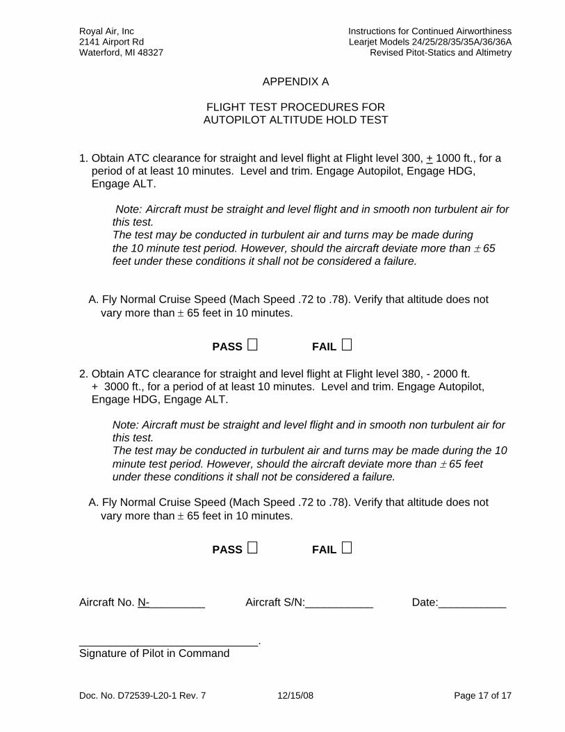
FLIGHT TEST PROCEDURES FOR AUTOPILOT ALTITUDE HOLD TEST
1. Obtain ATC clearance for straight and level flight at Flight level 300, + 1000 ft., for a period of at least 10 minutes. Level and trim. Engage Autopilot, Engage HDG, Engage ALT. Note: Aircraft must be straight and level flight and in smooth non turbulent air for
this test. The test may be conducted in turbulent air and turns may be made during the 10 minute test period. However, should the aircraft deviate more than ± 65 feet under these conditions it shall not be considered a failure.
A. Fly Normal Cruise Speed (Mach Speed .72 to .78). Verify that altitude does not vary more than ± 65 feet in 10 minutes.
PASS FAIL 2. Obtain ATC clearance for straight and level flight at Flight level 380, - 2000 ft. + 3000 ft., for a period of at least 10 minutes. Level and trim. Engage Autopilot, Engage HDG, Engage ALT. Note: Aircraft must be straight and level flight and in smooth non turbulent air for
this test. The test may be conducted in turbulent air and turns may be made during the 10 minute test period. However, should the aircraft deviate more than ± 65 feet under these conditions it shall not be considered a failure.
A. Fly Normal Cruise Speed (Mach Speed .72 to .78). Verify that altitude does not vary more than ± 65 feet in 10 minutes.
PASS FAIL Aircraft No. N-_________ Aircraft S/N:___________ Date:___________ _____________________________. Signature of Pilot in Command
Doc. No. D72539-L20-1 Rev. 7 12/15/08 Page 17 of 17