Embed Size (px)
Citation preview

©Copyright Task Force Tips, Inc. 2012 LIN-060 October 29, 2012 Rev00
MANUAL: FLIP TIPTM NOZZLEPATENTS PENDING
INSTRUCTIONS FOR INSTALLATION, SAFE OPERATION AND MAINTENANCE
WARNINGUnderstand manual before use. Operation of this device without understanding the manual and receiving proper training is a misuse of this equipment. Obtain safety information at www.tft.com/serial-number
WARNINGThis instruction manual is intended to familiarize fi refi ghters and maintenance personnel with the operation, servicing and safety procedures associated with the Flip Tip fi re fi ghting nozzles.
WARNINGThis manual should be kept available to all operating and maintenance personnel.
TASK FORCE TIPS, INC.MADE IN USA • www.tft.com
3701 Innovation Way, Valparaiso, IN 46383-9327 USA800-348-2686 • 219- 462-6161 • Fax 219-464-7155
Flip Tip OnlyNo Shutoff
Flip TipValve Shutoff
Flip TipValve Shutoff w/Pistol Grip
G-Force Flip TipValve Shutoff w/Pistol Grip
G-Force Flip TipValve Shutoff
DANGERPERSONAL RESPONSIBILITY CODE
The member companies of FEMSA that provide emergency response equipment and services want responders to know and understand the following:1. Firefi ghting and Emergency Response are inherently dangerous activities
requiring proper training in their hazards and the use of extreme caution at all times.
2. It is your responsibility to read and understand any user’s instructions, including purpose and limitations, provided with any piece of equipment you may be called upon to use.
3. It is your responsibility to know that you have been properly trained in Firefi ghting and /or Emergency Response and in the use, precautions, and care of any equipment you may be called upon to use.
4. It is your responsibility to be in proper physical condition and to maintain the personal skill level required to operate any equipment you may be called upon to use.
5. It is your responsibility to know that your equipment is in operable condition and has been maintained in accordance with the manufacturer’s instructions.
6. Failure to follow these guidelines may result in death, burns or other severe injury.
FEMSA Fire and Emergency Manufacturers and Service AssociationP.O. Box 147, Lynnfi eld, MA 01940 • www.FEMSA.org

©Copyright Task Force Tips, Inc. 2012 LIN-060 October 29, 2012 Rev002
Table Of Contents
1.0 MEANING OF SAFETY SIGNAL WORDS2.0 GENERAL INFORMATION 2.1 VARIOUS MODELS AND TERMS 2.2 NOZZLE COUPLINGS 2.3 COLOR CODED VALVE HANDLE AND PISTOL GRIP 2.4 REMOVABLE STREAM STRAIGHTENER 2.5 FLIP TIP LOCK 2.6 REAR SMOOTHBORE INSERTS 2.7 FRONT SMOOTHBORE NOZZLE 2.8 FRONT G-FORCE FOG NOZZLE 2.9 MECHANICAL SPECIFICATIONS3.0 FLOW CHARACTERISTICS and CHARTS4.0 FIRE GROUND USE OF FLIP TIP NOZZLES 4.1 USE WITH SALT WATER5.0 FIELD INSPECTION6.0 INSPECTION CHECKLIST7.0 ANSWERS TO YOUR QUESTIONS8.0 CLEANING OF PIVOTING JOINT9.0 EXPLODED VIEW AND PARTS LIST 9.1 TIP ONLY FLIP TIP 9.2 FLIP TIP WITH INTEGRATED VALVE 10.0 WARRANTY

©Copyright Task Force Tips, Inc. 2012 LIN-060 October 29, 2012 Rev003
1.0 MEANING OF SAFETY SIGNAL WORDSA safety related message is identifi ed by a safety alert symbol and a signal word to indicate the level of risk involved with a particular hazard. Per ANSI standard Z535.6-2006, the defi nitions of the four signal words are as follows:
DANGERDANGER indicates a hazardous situation which, if not avoided, will result in death or serious injury.
WARNINGWARNING indicates a hazardous situation which, if not avoided, could result in death or serious injury.
CAUTIONCAUTION indicates a potentially hazardous situation which, if not avoided, may result in minor or moderate injury.
NOTICENOTICE is used to address practices not related to personal injury.
2.0 GENERAL INFORMATIONThe Task Force Tips Flip Tip nozzles are designed to provide excellent performance under most fi re fi ghting conditions. Their rugged construction is compatible with the use of fresh water as well as fi re fi ghting foam solutions. Other important operating features include:
• Changeable smooth bore tips• Stream straightener removable through back coupling• TFT’s fi ve-year warranty and unsurpassed customer service
WARNINGThis equipment is intended for use by trained personnel for fi refi ghting. Their use for other purposes may involve hazards not addressed by this manual. Seek appropriate guidance and training to reduce risk of injury.
WARNINGNozzle reaction will vary as supply conditions change: such as opening or closing other nozzles, hose line kinks, changes in pump settings, etc. Changes in spray pattern or fl ushing will also affect nozzle reaction. The nozzle operator must always be prepared in the event of those changes. Failure to restrain nozzle reaction can cause fi refi ghter injury from loss of footing and/or stream protection.
WARNINGIf nozzle gets out of control or away from the operator, retreat from nozzle immediately. Do not attempt to regain control of nozzle while fl owing water. Injury from whipping can occur.
WARNINGWater is a conductor of electricity. Application of water solutions on high voltage equipment can cause injury or death by electrocution. The amount of current that may be carried back to the nozzle will depend on the following factors: Voltage of the line or equipment; Distance from the nozzle to the line or equipment; Size of the stream; Weather the stream is solid or broken; Purity of the water.1
CAUTIONFire streams are capable of injury and damage. Do not direct water stream to cause injury or damage to persons or property.
[Footnote 1: The Fire Fighter and Electrical Equipment, The University of Michigan Extension Service, Fourth Printing 1983, Page 47.]

©Copyright Task Force Tips, Inc. 2012 LIN-060 October 29, 2012 Rev004
2.1 VARIOUS MODELS AND TERMSThe TFT Flip Tip nozzle is available in several different confi gurations. The Flip Tip nozzle can be ordered with or without a pistol grip. Figure 2.1 shows the various models.
Flip Tip OnlyNo Shutoff
Ball Valve with Smoothbore Rearand Smoothbore Front
Ball Valve With Smoothbore Rearand G-Force Fog Nozzle Front
Locking Ring
Coupling
Pistol Grip
G-Force Fog NozzleSee LIG-010 for more informationOFFON
Flow Control
RemoveableStream Straightener
Available Rear Smoothbores:7/8”, 15/16”, 1.0”, 1-1/8”, or 1-3/8”
Available Front Smoothbores:1/2”, 5/8”, 15/16”, or 1.0”
Serial Number(on top of valve just ahead of coupling)
Serial Number(on top of valve just ahead of coupling)
Figure 2.1 Common Models and Terms

©Copyright Task Force Tips, Inc. 2012 LIN-060 October 29, 2012 Rev005
2.2 NOZZLE COUPLINGSNH (National Hose Threads per NFPA #1963) threads are standard on all nozzles. Other threads such as NPSH (National Pipe Straight Hose threads per ANSI/ASME #B1.20.7) can be specifi ed at time of order.
CAUTIONNozzle must be properly connected. Mismatched or damaged threads may cause nozzle to leak or uncouple under pressure and could cause injury.
CAUTIONDissimilar metals coupled together can cause galvanic corrosion that can result in the inability to unscrew the threads or complete loss of thread engagement over time. Per NFPA 1962 (2008 edition), if dissimilar metals are left coupled together an anti-corrosive lubricant should be applied to the threads. Also, the coupling should be disconnected and inspected at least quarterly.
2.3 COLOR CODED VALVE HANDLE AND PISTOL GRIPThe TFT Flip Tip is supplied with black valve handle covers and black pistol grip. Handle covers are available from TFT in various colors for those departments wishing to color code the nozzle to the discharge controls. A colored handle cover set will be sent upon receipt of the warranty card and color selection form by TFT. Your department’s name can also be engraved on the covers (see color selection form for more information).Handle covers are replaceable by removing the four screws that hold the handle covers in place. Use a 3/32” allen wrench when replacing screws. Pistol grip is replaceable by following TFT instruction sheet LTT-108.For standardization NFPA 1901-2009 (A.16.9.1) recommends the following color code scheme:
Preconnect #1 or Front Bumper Jump LinePreconnect #2 Preconnect #3 or discharge #1 Preconnect #4 or discharge #2 Discharge #3 Discharge #4 Discharge #5Foam LinesBooster Reels
OrangeRedYellowWhiteBlueBlackGreenRed w/ White border (Red/White)Gray
Other Colors Available:
• Pink• Tan• Purple
2.4 REMOVABLE STREAM STRAIGHTENERStream quality is generally improved with use of an integral stream straightener at the Flip Tip Inlet. The Flip Tip may be used without the straightener if so desired.
Stream Straightener
Groove goes in first
O-Ring (In groove in body used to retain stream straightener.If the straightener is removed, be sure to also removethe O-Ring)
Flip Tip with smooth bore frontflipped down
To remove the straightener, flipthe smooth bore front down,open valve fully, insert a woodendowel or similar tool to push the straightener out the rear of the coupling.
Figure 2.4 Removable Stream Straightener

©Copyright Task Force Tips, Inc. 2012 LIN-060 October 29, 2012 Rev006
2.5 FLIP TIP LOCKThe front nozzle is locked in both positions. To change positions follow the steps in fi gure 2.5.
Unlock
Flip Down
1
2
Unlock Flip Up1
2
Figure 2.5 Using the Flip Tip Lock
WARNINGWhen the front nozzle is in the down position the sealing surfaces are exposed. Avoid actions which can damage the sealing surface to prevent possible leakage and repairs.
CAUTIONThe Flip Tip pivoting joint is not sealed between the fully up and fully down positions. Shut off water fl ow before changing the front nozzle position to avoid spraying in unintended directions.
2.6 REAR SMOOTH BORE INSERTSThe rear smooth bore inserts may be removed by removing the retaining ring and pulling the insert out the front of the nozzle.
1-3/8” diameter if no insert is installed
Smooth bore insert
O-Ring
Retaining ring(use a pick or similar toolto remove)Insert removes in this direction
Figure 2.6 Rear Smooth Bore Inserts
2.7 FRONT SMOOTH BORE NOZZLE
Male Hose Thread for attaching a hose or other nozzle of the proper thread
Smooth bore nozzle
Figure 2.7 Front Smooth Bore Nozzles

©Copyright Task Force Tips, Inc. 2012 LIN-060 October 29, 2012 Rev007
2.8 FRONT G-FORCE FOG NOZZLEThe Flip Tip with G-Force fog nozzle allows selection between a smooth bore and a fog nozzle. The G-Force fog nozzle is available in fi xed opening, selectable, or automatic versions. See the G-Force owners manual LIG-010 for details.
G-Force Fog Nozzle
Rear Smooth bore insert
Figure 2.8 Front G-Force Fog Nozzle
CAUTIONThe lock for the front nozzle is not designed to withstand the full force of the nozzle reaction. Do not use the front nozzle in the down position as a handle to restrain the nozzle reaction. Injury from inadvertent unlocking may result.
2.9 MECHANICAL SPECIFICATIONSMaximum nozzle inlet pressure with valve shutoff* 300 psi 20 bar
Operating temperature range of fl uid 33 to 120º F 1 to 50º CStorage temperature range -40 to 150º F -40 to 65º CMaterials used Aluminum 6000 series hard anodized MIL8625 class 3 type 2,
stainless steel 300 series, nylon 6-6, nitrile rubber*Consult Factory for higher pressure applications
3.0 FLOW CHARACTERISTICS AND CHARTSThe Flip Tip nozzle has fi xed orifi ce sizes. Relationship of fl ow and nozzle pressure at each orifi ce size is shown below. If the nozzle is connected behind a different nozzle, use the fl ow charts for the outlet nozzle.
0 500 1000 1500 2000
0
1.4
2.7
4
5.5
7
0
10
20
30
40
50
60
70
80
90
100
0 100 200 300 400 500 600
FLOW (LPM)PR
ESSU
RE (B
AR)
PRES
SURE
(PSI
)
FLOW (GPM)
1 3/8 "
15/16"
1 1/8 "
1.0 "
1/2 "
7/8 "
5/8 "
Figure 3.0 Flip Tip Flow Chart

©Copyright Task Force Tips, Inc. 2012 LIN-060 October 29, 2012 Rev008
Flows at specifi c pressures for each orifi ce size are as follows:
1/2” TIPPRESSURE FLOW REACTION
PSI GPM LBS40 47 1550 53 1960 58 2370 62 2680 66 30
5/8” TIPPRESSURE FLOW REACTION
PSI GPM LBS40 73 2350 82 2960 90 3570 97 4180 104 47
7/8” TIPPRESSURE FLOW REACTION
PSI GPM LBS40 144 4650 161 5760 176 6970 190 8080 203 92
15/16” TIP
PRESSURE FLOW REACTION
PSI GPM LBS40 165 5350 185 6660 202 7970 218 9280 234 106
1” TIP
PRESSURE FLOW REACTION
PSI GPM LBS40 188 6050 210 7560 230 9070 249 10580 266 120
1-1/8” TIP
PRESSURE FLOW REACTION
PSI GPM LBS40 238 7650 266 9560 291 11470 315 13380 336 152
1-3/8” TIP
PRESSURE FLOW REACTION
PSI GPM LBS40 355 11350 397 14260 435 17070 470 19980 502 227
DANGERAn inadequate supply of nozzle pressure and/or fl ow will cause an ineffective stream and can result in injury, death or loss of property. See fl ow chart in Figure 3.1 or call 800-348-2686 for assistance.
4.0 FIREGROUND USE OF FLIP TIP NOZZLESIT IS THE RESPONSIBILITY OF THE INDIVIDUAL FIRE DEPARTMENT OR AGENCY TO DETERMINE PHYSICAL CAPABILITIES AND SUITABILITY FOR AN INDIVIDUAL’S USE OF THIS EQUIPMENT.Many factors contribute to the extinguishment of a fi re. Among the most important is delivering water at a fl ow rate suffi cient to absorb heat faster than it is being generated. The fl ow rate depends largely on the pump discharge pressure and hose friction loss. The pump discharge pressure can be calculated using a hydraulic equation such as:
PDP = NP + FL + DL + ELPDP = Pump discharge pressure in PSI
NP = Nozzle pressure in PSIFL = Hose friction loss in PSIDL = Device loss in PSIEL = Elevation loss in PSI
For additional information on calculating specifi c hose layouts, consult an appropriate fi re service training manual such at IFSTA, A Guide to Automatic Nozzles, or call TFT’s “Hydraulics Hotline” at 800-348-2686.
CAUTIONThe nozzle may become damaged if allowed to freeze while containing water. Always drainafter use to avoid damage and possible loss of use.
4.1 USE WITH SALT WATER
Use with salt water is permissible provided the nozzle is thoroughly cleaned with fresh water after each use. The service life of the nozzle may be shortened due to the effects of corrosion and is not covered under warranty.

©Copyright Task Force Tips, Inc. 2012 LIN-060 October 29, 2012 Rev009
5.0 FIELD INSPECTIONTFT’S Flip Tip is designed and manufactured to be damage resistant and require minimal maintenance. However, as the primary fi re fi ghting tool upon which your life depends, it should be treated accordingly.
WARNINGNozzle must be inspected for proper operation and function according to the inspection checklist in Section 6.0 before each use. Any nozzle that fails inspection is dangerous to use and must be repaired before using.
Performance tests shall be conducted on the Flip Tip nozzle after a repair, or anytime a problem is reported to verify operation in accordance with TFT test procedures. Consult factory for the procedure that corresponds to the model and serial number of the nozzle. Any equipment which fails the related test criteria should be removed from service immediately. Troubleshooting guides are available with each test procedure, or equipment can be returned to the factory for service and testing.
Factory service is available with repair time seldom exceeding one day in our facility. Factory serviced nozzles are repaired by experienced technicians to original specifi cations, fully tested and promptly returned. Any returns should include a note as to the nature of the problem, who to reach in case of questions and if a repair estimate is required.
Repair parts and service procedures are available for those wishing to perform their own repairs. Task Force Tips assumes no liability for damage to equipment or injury to personnel that is a result of user service.
CAUTIONAny alteration to the nozzle and its markings could diminish safety and constitutes a misuse of this product.
All Task Force Tips nozzles are factory lubricated with high quality silicone grease. This lubricant has excellent washout resistance and long term performance. If your department has unusually hard or sandy water, the moving parts may be affected. Foam agents and water additives contain soaps and chemicals that may break down the factory lubrication.
The moving parts of the nozzle should be checked on a regular basis for smooth and free operation, and signs of damage. IF THE NOZZLE IS OPERATING CORRECTLY, THEN NO ADDITIONAL LUBRICATION IS NEEDED. Any nozzle that is not operating correctly should be immediately removed from service and the problem corrected.
6.0 INSPECTION CHECKLISTNozzle must be inspected for proper operation and function according to the checklist before each use. Check that:
1) There is no obvious damage such as missing parts, broken or loose parts, damaged labels, etc.2) Coupling is tight and leak free3) Valve handle moves freely through full range, and shuts off fl ow.4) “OFF” position does fully shut off and fl ow is stopped.5) Nozzle fl ow is adequate as indicated by the pump pressure and nozzle reaction.6) Front end is tight and leak free7) Locking ring operates smoothly.
WARNINGAny Flip Tip nozzle failing any part of the inspection checklist is unsafe and must have the problem corrected before use. Operating a nozzle that fails any of the above inspections is a misuse of this equipment.
7.0 ANSWERS TO YOUR QUESTIONSWe appreciate the opportunity of serving you and making your job easier. If you have any problems or questions, our toll-free “Hydraulics Hotline”, 800-348-2686 or 1-219-462-6161 is normally available to you 24 hours a day, 7 days a week.

©Copyright Task Force Tips, Inc. 2012 LIN-060 October 29, 2012 Rev0010
8.2 FLIP TIP WITH INTEGRATED VALVE
G-FORCEFRONT
END
SEE LIG-010FOR G-FORCEPARTS LIST & EXPLODED VIEW
5325
5246
455143
5049
146
454443
29
28
27
26
25
11
9
10765
41
8
2
3
12
13
14151617 19
20
18
21 2221 23
24
31
2
30
3187
4140
3937 38
36
3533 34
32
25
42 47
48
42
25
25
47
48
©Copyright Task Force Tips, Inc. 2012 LIN-060 October 29, 2012 Rev0011
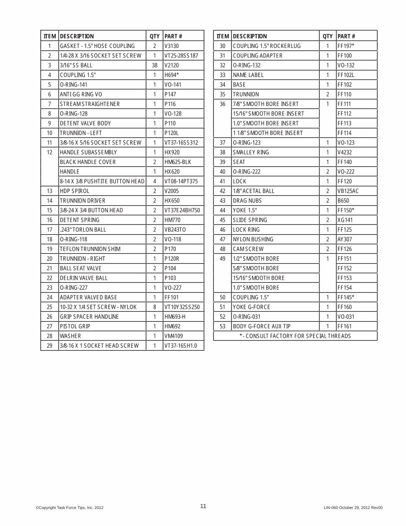
ITEM DESCRIPTION QTY PART #1 GASKET - 1.5" HOSE COUPLING 2 V31302 1/4-28 X 3/16 SOCKET SET SCREW 1 VT25-28SS1873 3/16" SS BALL 38 V21204 COUPLING 1.5" 1 H694*5 O-RING-141 1 VO-1416 ANTI GG RING VO 1 P1477 STREAM STRAIGHTENER 1 P1168 O-RING-128 1 VO-1289 DETENT VALVE BODY 1 P110
10 TRUNNION - LEFT 1 P120L11 3/8-16 X 5/16 SOCKET SET SCREW 1 VT37-16SS31212 HANDLE SUBASSEMBLY 1 HX920
BLACK HANDLE COVER 2 HM625-BLKHANDLE 1 HX6208-14 X 3/8 PUSHTITE BUTTON HEAD 4 VT08-14PT375
13 HDP SPIROL 2 V200514 TRUNNION DRIVER 2 HX65015 3/8-24 X 3/4 BUTTON HEAD 2 VT37E24BH75016 DETENT SPRING 2 HM77017 .243" TORLON BALL 2 VB243TO18 O-RING-118 2 VO-11819 TEFLON TRUNNION SHIM 2 P17020 TRUNNION - RIGHT 1 P120R21 BALL SEAT VALVE 2 P10422 DELRIN VALVE BALL 1 P10323 O-RING-227 1 VO-22724 ADAPTER VALVED BASE 1 FF10125 10-32 X 1/4 SET SCREW - NYLOK 8 VT10Y32SS25026 GRIP SPACER HANDLINE 1 HM693-H27 PISTOL GRIP 1 HM69228 WASHER 1 VM410929 3/8-16 X 1 SOCKET HEAD SCREW 1 VT37-16SH1.0
ITEM DESCRIPTION QTY PART #30 COUPLING 1.5" ROCKERLUG 1 FF197*31 COUPLING ADAPTER 1 FF10032 O-RING-132 1 VO-13233 NAME LABEL 1 FF102L34 BASE 1 FF10235 TRUNNION 2 FF11036 7/8" SMOOTH BORE INSERT 1 FF111
15/16" SMOOTH BORE INSERT FF1121.0" SMOOTH BORE INSERT FF1131 1/8" SMOOTH BORE INSERT FF114
37 O-RING-123 1 VO-12338 SMALLEY RING 1 V423239 SEAT 1 FF14040 O-RING-222 2 VO-22241 LOCK 1 FF12042 1/8" ACETAL BALL 2 VB125AC43 DRAG NUBS 2 B65044 YOKE 1.5" 1 FF150*45 SLIDE SPRING 2 XG14146 LOCK RING 1 FF12547 NYLON BUSHING 2 AY30748 CAM SCREW 2 FF12649 1/2" SMOOTH BORE 1 FF151
5/8" SMOOTH BORE FF15215/16" SMOOTH BORE FF1531.0" SMOOTH BORE FF154
50 COUPLING 1.5" 1 FF145*51 YOKE G-FORCE 1 FF16052 O-RING-031 1 VO-03153 BODY G-FORCE AUX TIP 1 FF161
* - CONSULT FACTORY FOR SPECIAL THREADS

©Copyright Task Force Tips, Inc. 2012 LIN-060 October 29, 2012 Rev00
TASK FORCE TIPS, INC.MADE IN USA • www.tft.com
3701 Innovation Way, Valparaiso, IN 46383-9327 USA800-348-2686 • 219- 462-6161 • Fax 219-464-7155
9.0 WARRANTYTask Force Tips, Inc., 3701 Innovation Way, Valparaiso, Indiana 46383-9327 USA (“TFT”) warrants to the original purchaser of its Flip Tip series nozzles (“equipment”), and to anyone to whom it is transferred, that the equipment shall be free from defects in material and workmanship during the fi ve (5) year period from the date of purchase.TFT’s obligation under this warranty is specifi cally limited to replacing or repairing the equipment (or its parts) which are shown by TFT’s examination to be in a defective condition attributable to TFT. To qualify for this limited warranty, the claimant must return the equipment to TFT, at 3701 Innovation Way, Valparaiso, Indiana 46383-9327 USA, within a reasonable time after discovery of the defect. TFT will examine the equipment. If TFT determines that there is a defect attributable to it, TFT will correct the problem within a reasonable time. If the equipment is covered by this limited warranty, TFT will assume the expenses of repair.If any defect attributable to TFT under this limited warranty cannot be reasonably cured by repair or replacement, TFT may elect to refund the purchase price of the equipment, less reasonable depreciation, in complete discharge of its obligations under this limited warranty. If TFT makes this election, claimant shall return the equipment to TFT free and clear of any liens and encumbrances.This is a limited warranty. The original purchaser of the equipment, any person to whom it is transferred, and any person who is an intended or unintended benefi ciary of the equipment, shall not be entitled to recover from TFT any consequential or incidental damages for injury to person and/or property resulting from any defective equipment manufactured or assembled by TFT. It is agreed and understood that the price stated for the equipment is in part consideration for limiting TFT’s liability. Some states do not allow the exclusion or limitation of incidental or consequential damages, so the above may not apply to you.TFT shall have no obligation under this limited warranty if the equipment is, or has been, misused or neglected (including failure to provide reasonable maintenance) or if there have been accidents to the equipment or if it has been repaired or altered by someone else.THIS IS A LIMITED EXPRESS WARRANTY ONLY. TFT EXPRESSLY DISCLAIMS WITH RESPECT TO THE EQUIPMENT ALL IMPLIED WARRANTIES OF MERCHANTABILITY AND ALL IMPLIED WARRANTIES OF FITNESS FOR A PARTICULAR PURPOSE. THERE IS NO WARRANTY OF ANY NATURE MADE BY TFT BEYOND THAT STATED IN THIS DOCUMENT.This limited warranty gives you specifi c legal rights, and you may also have other rights which vary from state to state.