Embed Size (px)
Citation preview

NR
121
3_EN
/FR
_Ind
.A
Art
: 51
0014
3
instructions for start-upWEatHErproof actuators
sq & st intElli+(Also suitable for MA, MB, MAS, MBS INTELLI+)
ManuEl dE MisE En sErvicEpour sErvoMotEurs EtancHEs
ModèlEs sq & st intElli+(Aussi applicable pour MA, MB, MAS, MBS INTELLI+)
SQST
GammeRange

3
1 Safety information Page 32 Product overview Page 33 Storage Page 44 Manual override operation and declutching Page 45 Actuator on valve assembly Page 56 Setting of mechanical stops (SQ range) Page 57 Electrical connection Page 68 Actuator on valve setting introduction Page 69 Remote control Page 710 Local control using buttons and display Page 811 Navigating in the menus Page 912 Selecting the display language Page 1013 Password Page 1114 Check menu flowchart Page 1215 Set up and change menu flowchart Page 1316 Adjusting an actuactor on a valve Page 1417 Position signal and positioner Page 1518 Commands Page 1619 Local PC communication Page 2020 Setting and viewing torque values Page 2121 Customizing status and control indications Page 2322 Customizing fault relay Page 2523 Timing movement travel Page 2624 Viewing actuator history Page 2725 Accessing data sheet Page 2826 Creating or changing password Page 2927 Using analogue position signal (depending on model) Page 2928 Use as a positioner with an analogue control signal (depending on model) Page 3029 Using fieldbus control (depending on model) Page 3130 Using in case of power supply lost (with battery depending on model) Page 3231 Changing the direction of the display Page 3232 Fuse protection Page 3333 Using in separated box Page 3334 Maintenance Page 3335 Troubleshooting Page 3436 Diagram with options (Internal wiring different on SQ6 / SQ15) Page 36
CONTENTS 1 SAFETY INFORMATION
This device complies to current applicable safety standards. Installation, maintenance and use of this apparatus by skilled and trained staff only.
Please read carefully the whole document prior to mounting and starting-up.
2 PRODUCT OVERVIEW
Blue selectorOpen/Close &
Up-Down Scroll
display
Infrared port
Open & closed valve indication
LEDs
Red selectorLocal/Distance/Stop & validation (OK)
Quarter-turn +FPi box Multiturn + FPi box
ST175 & ST220 Multiturn Combi quarter-turn +FPi box

4 5
SQ20 to SQ80 models:In order to ease the manual override, some of these actuators are equipped with declutchable intermediate gears. By moving the clutch lever, the motor is physically disengaged from the gears. Once the manual handwheel operation has been completed, do not forget to clutch the motor back. Otherwise, once started-up, it would run and heat up until the motor thermal protection switch closes. If repeated, these conditions can generate a motor breakdown .
SQ100 to SQ1000 and ST6 models:These actuators are provided with an automatic declutching handwheel, with motor drive priority. In order to operate manually the actuator, turn the arrow of the handwheel clutch button in front of the triangular sign on the housing (it might be necessary to turn the handwheel by a few degrees to release the claws). When the motor starts, it returns automatically into declutched position.
All ST models except ST6Except ST6, all ST range actuators are provided with an automatical declutchling handwheel, with motor drive priority. Operating direction is normally indicate on the handwheel.
5 ACTUATOR ON VALVE ASSEMbLY
Actuator should be secured directly to the valve (or the gearbox) using proper bolts or via a proper interface. After assembly, the actuator can operate in any position. However, cable glands should not be oriented upwards (loss of water tightness) and the motor will preferably not be positioned at the bottom (potential internal condensation trap)
Note 1: do not handle the actuator by handwheel, it could damage the gears.Note 2: see details on storage precaution prior to starting-up.Note 3: Greasing of A form drive bush has to be done prior to mounting actuator on valve (in the
case of a rising stem valve).
6 SETTING OF MEChANICAL STOPS (SQ ONLY)
Mechanical stops description and function (1/4 Turn only):These items avoid any over-travelling during operations. The stops can be positioned either on the actuator itself or on the 1/4 Turn worm gearbox if any.
Actuators and gears are supplied and tested for a 90° operation. Fine adjustment of the stop screws position is possible within a limit of ± 2° maximum.
WARNINGOn quarter-turn actuators, mechanical end stops, located either on the actuator or the
gearbox, mechanically limit the actuator travel during manual operation. It is mandatory that the motor stops, in both directions, on the travel limit switch and not on the mechanical end stop (check available extra travel to the stop with the handwheel).
3 STORAGE
IntroductionAn actuator consists of electrical components plus mechanical parts which have life-long lubrication. Although the assembly is contained in a waterproof housing, the actuators may suffer from oxidation, become clogged or seize during commissioning if it has not been stored correctly.
StorageActuators must be stored under cover in a clean, dry place which is protected against variations in temperature.Avoid storing directly on the ground. If stored in areas subject to damp, apply power to the actuator to dry it out electrically. Check to ensure that the cable entries are sealed.Ensure electrical component covers and compartments are properly sealed.In case of a valve with an important stem lift, check that the stem protection cover is mounted on the actuator. If not, assemble it with a weak sealing paste.
Inspection following storage
1. If stored for less than one year: •Visualinspectionofelectricalparts. • Operate buttons, selectors, etc. manually to ensure that they can be used without difficulty. •Performafewmovementsmanually. •Checkconsistencyofgrease. •Commissiontheactuator.
2. If stored for more than one year: • Long-term storage causes the consistency of the grease to change. To avoid any
grease-drying problem, do some rotations of the actuator several times a year by using motor or manual override.
•Visualinspectionofelectricalparts. • Operate buttons, selectors, etc. manually to ensure that they can be used without difficulty. • For the actuators equipped with battery option. During the storage period, the circuit
is in low comsumption mode which allows to get a long lifetime of the battery. Beyond a storage time of 3 years it is better to replace the batteries at the commissioning. You can check the battery status at any time on the display.
4 MANUAL OVERRIDE OPERATION AND DECLUTChING
The handwheel does not turn during electrical operation.
SQ6 and SQ15 models:These actuators are equipped with a manually declutchable handwheel.To operate manually the actuator, turn while pulling the handwheel in order to mechanically engage it.To declutch the handwheel, just push it back towards the actuator body.

6 7
7 ELECTRICAL CONNECTION
The power supply voltage and frequency are indica-ted on the identification tag and (or) on the electric wiring diagram. Only the cover of the connection box/compart-ment requires to be open for electrical connection. The other covers should not be removed at the risk of introducing mois-ture into the electronic controls. A wiring diagram is normally supplied with the actuator. If this is not the case, please ask our customer service. Operating procedure :
a) Check the power supply characteristics with respect to the rating nameplate.
In 3 phase, the phases order is not important as the INTEL-LI+ system corrects the direction of rotation automatically.b) Open the terminal box (fig. 2), connect the power and
control circuits (ring tongue not supplied). The screw diameters is 3mm for the control and 4mm for the power
c) Check the wiring and the cover seal position.d) Close the compartment and make sure that the cover
screws and cable glands are properly tighten.
Wiring specifications on SQ6 & SQ15On SQ6 & SQ15 actuators, it’s necessary to use shielded cables. The cable gland must propose an earth connection and the cable shield must be connected to the earth as follow :
a) Strip the cableb) Insert the cable through cable glandc) Fold the shield of the cable to bring it into contact with
the inside of cable gland.A quick-fuse must be installed on primary phase of the actuator. The fuse, not supplied by Bernard Controls, can be placed inside or outside the junction box. Size of quick-fuse :
1x230VAC50Hz:.........................................6,3x32mm1A1x115VAC60Hz:...........................................6,3x32mm1.8A3x400/460VAC50Hz:...........................6,3x32mm0,5A1x24VAC50-60Hz:...................................6,3x32mm10A
8 ACTUATOR ON VALVE SETTING INTRODUCTION
Each INTELLI+ actuator is set and checked at the factory.If the actuator is delivered mounted on top of a valve, the open and closed positions as well as the maximum torque values should have been adjusted by the valve supplier.If an actuator on valve setting has to be performed or optimised, it can be done by simply connec-ting the power supply. All settings and configurations can then be performed in a non-intrusive way using the blue and red rotating knobs together with the graphical display.The following chapters of this document include all the information necessary to perform actuator on valve settings:
§11.NAVIGATINGINTHEMENUS§12. SELECTING THE DISPLAY LANGUAGE§20.SETTINGANDVIEWINGTORQUEVALUES(incaseofclosingontorque)
§20.1 Closing type§20.2 Setting torque
§16.ADJUSTINGANACTUACTORONAVALVE
9 REMOTE CONTROL
The INTELLI+ actuator’s remote control system can be operated using an external or an integral voltage supply. The input circuits are fully opto-isolated. The self-hold pulse command system re-quires four connecting wires on the client terminal strip: Common, stop, open and close. If the stop push-button is not used, do not connect the STOP wire, open (or close) contact must be maintained to operate the actuator.
9.1 DRY CONTACT CONTROL
In case of dry contact control, a jumper must be fitted across customer terminal 5-6.
9.2 VOLTAGE CONTROL
Remote control can use either in AC or DC voltage.Usecommonterminal5forlowvoltagesfrom10to55V.Usecommonterminal4forvoltagesfrom55to250V.
Caution: never connect voltage sources above 55Von common terminal 5.
24V
1,2W
-
+
4
5
6
7
8
9
10
STOP
CLOSE
OPEN
Pulse remote command(self-holding)
24V
1,2W
-
+
4
5
6
7
8
9
10
CLOSE
OPEN
Remote commandwithout self-holding
4
5
6
7
8
9
10
STOP
CLOSE
OPEN
10 - 55V ~ 4
5
6
7
8
9
10
55 - 250V ~
STOP
CLOSE
OPEN

8 9
10 LOCAL CONTROL USING bUTTONS AND DISPLAY
The local control facility provides a means of operating the actuator electrically without using an external control circuit. There is a red knob for selecting remote control, local control or disabled (off). This knob can be locked in the 3 positions using a 6 mm padlock.The local open/close blue knob is used to operate the actuator in the direction required. Movement can be halted locally by turning the local/ remote selector switch briefly to the STOP position.
The display shows the position of the valve as a percentage of opening when it is partially open. The display shows “Closed” when the valve is closed. The display shows “Open” when the valve is open.The display is factory set to show the instantaneous torque as a percentage of the maximum actuator torque value < 10% indicates the minimum torque value.
Symbols that may appear on the display:
Aremotecommandinhibitsthelocalcontrols(see§18.2)Theactuatorreceivesanemergencyshutdowncommand(see§18.2)An infrared link is detected (see § 19.1)A bluetooth link is detected (Option: alternative solution to infrared link : see § 19.2)indicates the presence of an alarm. (see §24.2 for the types of alarm)In case of a battery option, the icon blinks if the battery voltage is low.This icon indicates that the control is proportional (4-20 mA i.e) and the value of the input signal (setpoint) is indicated in %.The BUS marker indicates there is a bus communication card. The marker is followed by a square that shows you the communication status (see specific documentation of the installed bus).1 and 2 indicate the presence of a redundant communication card (2 communication channels). The number is followed by a square indicating the status of each communi-cations channel (see the specific doc. of the installed bus).
ESDIR
1 2
0%
BUS
ESDIR
1 2
0%
BUS
ESDIR
1 2
0%
BUS
ESDIR
1 2
0%
BUS
ESDIR
1 2
0%
BUS
ESD
0%
BUS
1 2
ESD
0%
BUS
1 2
ESDIR
1 2
0%
BUS
20% Open
Closed
Open
Torque 60%
11 NAVIGATING IN ThE MENUS
The selector switches used for operating the actuator’s electrical motor drive is also used to navi-gate into the INTELLI+ menus and thus to have access to the settings.
11.1 SELECTORS
Blue selector (on the right)- choice selection
Red selector (on the left)- selector on OK: choice validation- selector on OFF: exit the menu at any time
11.2 MAIN MENU
- Set the selector on local- Keep the red selector on local stop and at the same time move the blue selector upwards and
then downwards. The display shows:
- Release the selector, it goes to “local” position.
To read the menu, turn the blue selector up or down to scroll through the menu options on the bottom line of the display.
11.3 SELECT A MENU OR AN OPTION
Select Confirm Select then confirm (blue selector) (red selector) (red selector then blue selector)
When the option you want is displayed, turn the red selector from local stop to OK. The option is then displayed in upper-case characters on the first line and sub-menu items can be viewed on the second line.
MENUexit setup
MENUexit set uplanguagechecksetupchangeexit set up
LANGUAGEfrenchenglishdeutschspanishPortuguesItalianRussianchinese
MENUlanguagechecksetupchangeexit set up

10 11
11.4 SAVING ThE ChANGES
To save changes made in the CHANGE menu, you have to exit each menu in turn by selecting return until the display shows: (change ok?)
Select Confirm Select then confirm
11.5 ExITING ThE MENU AT ANY TIMES
To exit the menu at any time, turn the red selector to the “OFF” position.
11.6 MAIN MENU DESCRIPTION
Language: to choose the displayed language.Check: to view all actuator settings and configuration data. No changes can be made and this option can be accessed without a password.Setup: to adjust the actuator on the valve. A password is needed to access this option if a password has been registered.Change: to change the actuator configuration. A password is needed to access this option if a password has been registered.
Refer to §14 to get details about the Check, Setup and Change menus.
12 SELECTING ThE DISPLAY LANGUAGE
SelectlanguageintheMENUandturntoOKtoconfirm.Select the language you want and turn to OK to confirm.
TORQUEreturntorque settingmeasured torquetorque curveclosing typereturn
CHANGE(change ok?)no change
CHANGEreturnactivitycommandstorquedata sheet
MENUexit set uplanguagechecksetupchangeexit set up
LANGUAGEfrenchenglishdeutschspanishPortuguesItalianRussianchinese
13 PASSWORD
Users wishing to access the change or set up menus are prompted to enter a password.The default setting is no password and the change or set up menus can be accessed by selecting OK.
It’s highly recommended to add a password to restrict access to changes
Create passwordRefer to section §26 “How to create or change a password”
Enter passwordTo enter password at the prompt CODE ? Enter 1st digit with the blue selector and then turn to OK to confirm.Enter 2nd digit with the blue selector and then turn to OK to confirm.Enter 3rd digit with the blue selector and then turn to OK to confirm.The user can continue if the access code is correct.Select OK to confirm.
user codeOK
ok
CODE?0
user codeOK
ok

12 13
EXITSETUP
LANGUAGE
CHECK
SET UP
CHANGE
EXIT SETUP
MENU RETURN
ACTIVITY
ALARMS
COMMANDS
no alarm
return
aux. command 1
aux. command 2
local command
local stop
remote stop
priority
fault tolerance
partial stroke
return
number of starts
running time
starts last 12h
handwheel action
TORQUE return
torque setting
measured torque
torque curve
closing mode
sensor model
DATA SHEET return
valve tag number
actuator number
entry code
operating class
manufacture date
characteristics
software version
POSITION return
close direction
opt position signal
sensor model
POSITIONER return
signal range
dead band %
loss of signal
proport pulseSIGNALING
return
opposite display
torque display
lights
LOCALINDICATION
return
relay 1
relay 7
dafault relay
REMOTEINDICATION
TIMER return
operating time
timer open time
timer closed time
temporised zone
FIELDBUS return
according to bus interface
14 ChECK MENU FLOWChART
EXIT SET UP
LANGUAGE
CHECK
SET UP
CHANGE
EXITSET UP
MENU RETURN
ACTIVITY
COMMANDS
return
aux. command 1
aux. command 2
local command
local stop
remote stop
priority
fault tolerance ESD
partial stroke
return
number of starts
running time
starts last 12h
handwheel action
TORQUE return
torque setting
measured torque
closing mode
DATASHEET return
valve tag number
entry code
characteristics
POSITION return
close direction
opt position signalPOSITIONER return
signal range
dead band %
lost signal
proportional pulseSIGNALING
return
opposite display
torque displayed
lights
LOCALINDICATION
return
relay 1
relay 7
default relay
REMOTEINDICATION
TIMER return
operating time
timer open time
timer close time
temporised zone
FIELDBUS returnaccording tointerface bus
CLOSING MODE
CLOSEDIRECTION
POSITIONSETTING
on (position)
on (torque)
on (torque) O/C
(CW)
(CCW)
return
valve closed?
valve open?
automatic
RETURN
(change ok?)
(no change)usercode
BLUETOOTH return
PIN code
On/Off
15 SET UP AND ChANGE MENU FLOWChART
14 15
16 ADJUSTING AN ACTUACTOR ON A VALVE
The SET UP menu is used to set the open and closed positions when the actuator has been installed on the valve. Settings can be made manually by choosing the open and closed positions, or automatically. In automatic mode, the actuator rotates and halts at the end positions in response to the torque limiter. INTELLI+ then determines the stoppositions. Set up manually if you want to avoid having theactuator stop in response to the torque limiter or if you wantto choose the stop positions yourself.
16.1 MANUAL SET UP
Select set upintheMENUandturntoOK to confirm.Select closing mode in the SET UP menu and turn to OK to confirm.Select whether valve to close on basis of torque or position(both open and close actions can also be set on torque). Select OK to confirm.Select close direction and turn to oK to confirm.Indicate normal close direction (generally clockwise).Select OK to confirm.
Select position setting and turn to OK to confirm.Select valve closed ? to make closure setting Turn to OK to confirm. When (no) is displayed, turn to OK to confirm. The display shows:
Set the valve in the closed position either with the handwheel or using the motor control. Use the same closing mode as previously, i.e. close to the torque limiter for torque-type closure and without torque limiter activation for position-type closureWhen the valve is in the correct position perform local stop to return to the menu.When (yes) is displayed, turn to OK to confirm.If in doubt about the setting, select (no) and start againPosition ok is displayed. Turn to OK to continue.Now set the valve open position.When valve open ? is displayed turn to OK to confirm.When (no) is displayed turn to OK to confirm. The display shows:
Set the valve in the closed position either with the handwheel or using the motor control. Ensure that there is no possibility that the actuator will reach the mechanical stop.When the valve is in the correct position, perform local stop to return to the menu.When (yes) is displayed turn to OK to confirm. If in doubt about the setting, select (no) and start again Position ok is displayed. Turn to OK to continue. The display shows the stroke travel distance at the end of the set up process. Turn to OK to confirm and return to control mode.
SET UPreturnclosing modeclosing directionposition settingreturn
POSITION SETTINGreturnvalve closed?valve open?automaticreturn
close by buttonreturn = local stop
position ok
ok
Note: At this stage of the set up operation, the selectors used to navigate
through the menu become active for performing actuator control functions
again. The knob has to be held until the required position is obtained. The self-hold
capability is not active during set up.
open by buttonreturn = local stop
measured stroke89°
measured stroke38turns
16.2 AUTOMATIC SET UP
Select set upintheMENUandturntoOK to confirm.Select closing mode in the SET UP menu and turn to OK to confirm. Select whether valve to close on basis of torque or position both open and close actions can be set on torque). Turn to OK to confirm. When close direction is displayed turn to OK to confirm. Indicate normal close direction (generally clockwise). Turn to OK to confirm.When position setting is displayed turn to OK to confirm.Select automatic on POSITION SETTING menu
The automatic setting cycle begins when the user turns to OK.The actuator detects the end positions by means of the torque limiter and then positions itself at mid-stroke to test its inertia in both directions of travel.INTELLI+ determines stop positions at 0 and 100% on the basis of the closing mode setting and the actuator inertia.The display shows the stroke travel distance at the end of the set up processTurn to OK to confirm and return to control mode.
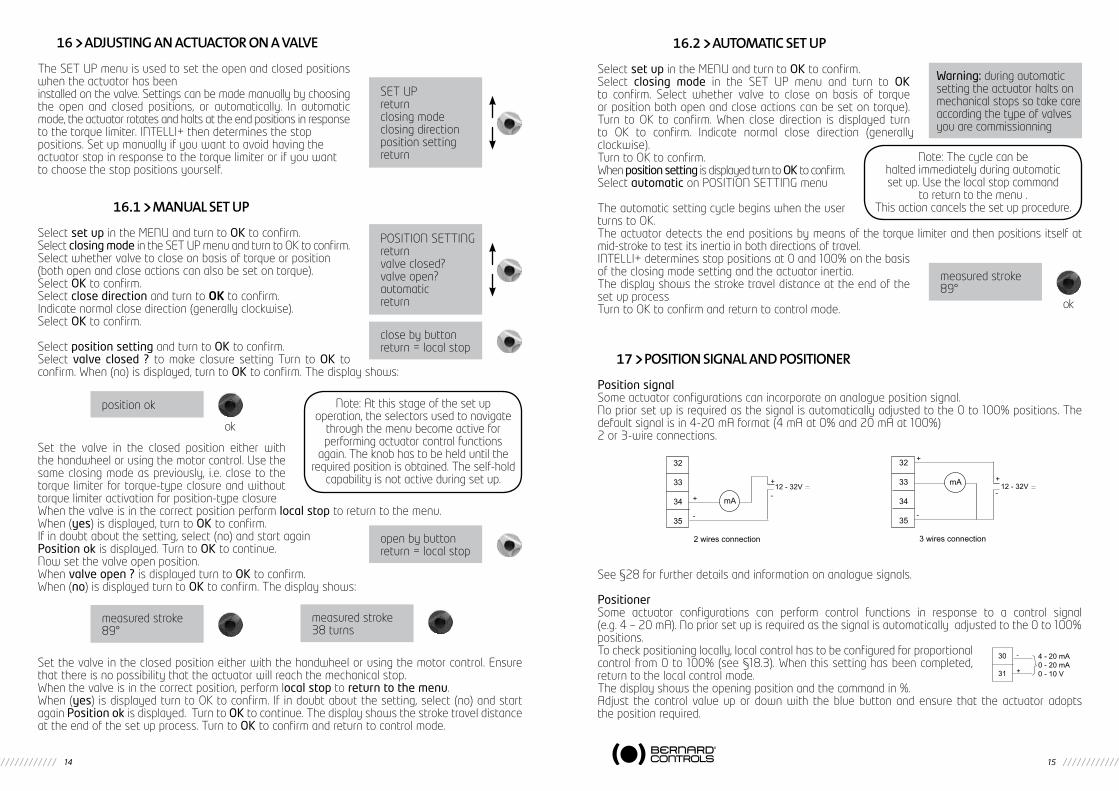
17 POSITION SIGNAL AND POSITIONER
Position signalSome actuator configurations can incorporate an analogue position signal.No prior set up is required as the signal is automatically adjusted to the 0 to 100% positions. The default signal is in 4-20 mA format (4 mA at 0% and 20 mA at 100%)2 or 3-wire connections.
See§28forfurtherdetailsandinformationonanaloguesignals.
PositionerSome actuator configurations can perform control functions in response to a control signal (e.g. 4 – 20 mA). No prior set up is required as the signal is automatically adjusted to the 0 to 100% positions.To check positioning locally, local control has to be configured for proportional controlfrom0to100%(see§18.3).Whenthissettinghasbeencompleted,return to the local control mode. The display shows the opening position and the command in %.Adjust the control value up or down with the blue button and ensure that the actuator adopts the position required.
Warning: during automatic setting the actuator halts on mechanical stops so take care according the type of valves you are commissionning
Note: The cycle can be halted immediately during automatic set up. Use the local stop command
to return to the menu .This action cancels the set up procedure.
measured stroke89°
ok
32
33
34
35
2 wires connection
12 - 32V
mA+
-
+
-
32
33
34
35
3 wires connection
12 - 32VmA
+
-
+
-
30
31
-
+
4 - 20 mA0 - 20 mA0 - 10 V

16 17
OneoftheauxiliarycommandshastobesettoAUTO/ON-OFFtooperateremotely(see§18.2).The actuator is on positioner control when this setting has been completed. The auxiliary command must be switched for On-Off commands. This auxiliary command is used for selecting positioner or on-off control remotely. See§28forfurtherdetails,particularlyregardingdeadbandsettings.
18 COMMANDS
Standard remote command modes are described in §9 above. This section covers additional control methods.
18.1 REMOTE CONTROL VIA SINGLE CONTACT
The actuator can be controlled via a single external contact.- Contact closed: valve opens- Contact open: valve closes
Theactuatorhastobeconfiguredforprioritytoopen(see§18.6)The command can be made the other way round:
- Contact closed: valve closes- Contact open: valve opens
Inthiscase,theactuatorhastobeconfiguredforprioritytoclose(see§18.6)
15.2 AUxILIARY REMOTE CONTROLS
Two further remote commands are available and can be configured for the installation.
These commands can be assigned to specific functions.
4
5
6
7
8
9
10
OPEN
Opening by singlecontact closing
4
5
6
7
8
9
10
CLOSE
Closing by singlecontact closing
Configuration: priority to open Configuration: priority to close
CLOSE
OPEN
Aux. command 1
Aux. command 2
STOP
4
5
6
7
8
9
10
11
12
CLOSE
OPEN
Aux. command 1
Aux. command 2
STOP
4
5
6
7
8
9
10
11
12
55 - 250V
10 - 55V
SelectchangeintheMENUandturntoOKtoconfirm.Select commands in the CHANGE menu and turn to OK to confirm.Select aux. command 1 or aux. command 2 in theCOMMANDSmenuand turn toOK to confirm. Select acommand with the blue selector.By default, aux. command 1 is assigned to local command inhibit and aux. command 2 to ESD close.If aux. command 1 and aux. command 2 are set to emergency functions, aux. command 2 has priority.
Description of the commands:- local/remote replaces local/remote switch on the actuator for
enabling remote control or local control from a remote location.Turn to OK to confirm and then select contact status for performing this command: Turn to OK to confirm.
- local + remote/remote: same as above, but this command allows local and remote modes to be enabled at the same time.
- local command inhibit: local command inhibit is a remote command. This command overrides any open or close commands made locally and enables remote commands, even if the local/re-mote selector on the actuator is on local.
Turn to OK to confirm and then choose whether or not to maintain local stop capability. The standard setting is for local stop and general shutdown to remain possible on the actuator. Select local off (no) to inhibit local stop as well.Turn to OK to confirm and then select contact status for performing this command (as described above).Turn to OK to confirm.
- open / close inhibit: this command is used to prevent the actuator from opening or closing.
For example, a main valve has a by-pass valve and should not open unless the by-pass valve is already open. In this case, a limit switch on the by-pass valve could be used to prevent the main valve from opening unless the limit switch has been activated.
Turn to OK to confirm and then select contact status for perfor-ming this command (as described above). Turn to OK to confirm.
AUX.COMMAND1(no assigned)(local/remote)(local+remote/remote)(local command inhibit)(open inhibit)(close inhibit)(auto / on-off)ESD closeESD openESD stoppartial stroke
LOCAL/REMOTEcontact (c) = remotecontact (o) = remote
Aux. command 1 Selector local/remote
Actuator terminal
11
1rst choice: closed contact = remote commands.2nd choice: open contact = remote commands
If you just want to check settings without making changes, select check instead
of change in the main menu.
LOCCMDINHIBITlocal off (yes)local off (no)
OPEN INHIBITcontact (c) = inhibitcontact (o) = inhibit
LOCCMDINHIBITcontact (c) = inhibitcontact (o) = inhibit

18 19
- auto/on off: actuators used to control equipment with the positioner function can be a DC signal driven (e.g. 4-20 mA) or via open/close/stop commands. The auto/ on-off command provides a means of switching over from one command mode to the other.
Turn to OK to confirm and then select contact status for performing this command (as described above).Turn to OK to confirm.
- ESD close / open: ESD (Emergency Shut Down) commands are emergency commands and have priority over all other commands. The emergency command may be to open or close the valve or to cause an immediate stop, depending on the use of the valve.
Turn to OK to confirm and then select contact status for performing this command (as described above). Turn to OK to confirm
Note: the emergency command cannot be executed when the local / remote selector is on the OFF position.Degradedmodesee§18.7
- partial stroke:partialstrokeisacommandforperformingperiodicfunctiontests(see§18.8).
18.3 LOCAL COMMANDS
Local commands are self-held in the standard configuration (The control only needs to be pressed once to perform an open or close command).Proceed as follows to override this feature and require open or close commands to be held down throughout the action:Select changefromtheMENUandturntoOK to confirm.Select commands in the CHANGE menu and turn to OK to confirm.Select localcommandintheCOMMANDSmenuandturntoOK to confirm.Select (maintained) and turn to OK to confirm.For a local command with increments from 0 to 100%, select (0 – 100%).The command then takes the value of the current position and is displayed under the position. The right-hand selector can then be used to change the command value in increments of 1%.
18.4 LOCAL STOP
The actuator can be stopped locally in the standard configuration, even if it is set on remote control. To disable the local stop action when the selector is on remote, select local stopintheCOMMANDSmenu and then select (no).
18.5 REMOTE STOP
In the standard configuration, remote stops are performed by opening a contact (whereas the open or close command is made by closing a contact). To control the remote stop in the same way as open or close actions, select remote stopintheCOMMANDSmenuandthenselectcontact (c)=stopNote: The open and close commands have priority over stop.
AUTO / ON - OFFcontact (c) = autocontact (o) = auto
ESD CLOSEcontact (c) = commandcontact (o) = command
18.6 OPEN OR CLOSE PRIORITY
There are no priorities on open or close in the standard configuration. Priorities are used to reverse the direction of travel when an action is in progress without having to give a stop command. In this case, priority must be given to open and close actions.
Assign priority to one direction of rotation: if the opening action is assigned priority and the actuator receives an open and a close command simultaneously, the actuator will open.See§18.1formaking single contact commands.Select changeintheMENUandturntoOK to confirm.Select commands in the CHANGE menu and turn to OK to confirm.Select priorityintheCOMMANDSmenuandturntoOK to confirm.Select (open), (close) or (open and close) and turn to OK to confirm.
18.7 ESD IN DEGRADED MODE
Protection devices are active in the standard configuration and therefore halt the operation of the actuator if a fault occurs.It is possible to allow the actuator to deliver up to 100% of its nominal torque to ensure fault-tole-rant operation if an emergency command is given (see descrip-tion of auxiliary commands 1 or 2). It’s also possible to by-pass the motor thermal protector (Risk of motor damage).Select changeintheMENUandturntoOK to confirm.Select commands in the CHANGE menu and turn to OK to confirm.SelectfaulttoleranceESDintheCOMMANDSmenuandturntoOK to confirm.When an option is selected, the brackets are removed and an asterisk is displayed in front of the selected item. Turn to OK to cancel selection.
18.8 PARTIAL STROKE
It may be useful to operate motorised valves which are rarely used from time to time to ensure that they remain available for service. INTELLI+ has the ability to test actuator functions when requested by the user. This test consists of rotating the valve a certain distance (e.g. 10% of full tra-vel) and then returning it to the original position. The time taken to travel the distance is monitored and an alarm is activated if the specified time is exceeded. The user gives this command using an auxiliary input on the actuator (see configuration information). The test runs automatically. Signals - partial stroke in progress and partial stroke fault, need to be configured on two relays.
FAULT TOLERAN. ESDreturn(no thermal overload)(100% torque)return
4
5
6
7
8
9
10
STOP
CLOSE
OPEN
10 - 55V ~ 4
5
6
7
8
9
10
55 - 250V ~
STOP
CLOSE
OPEN
20 21
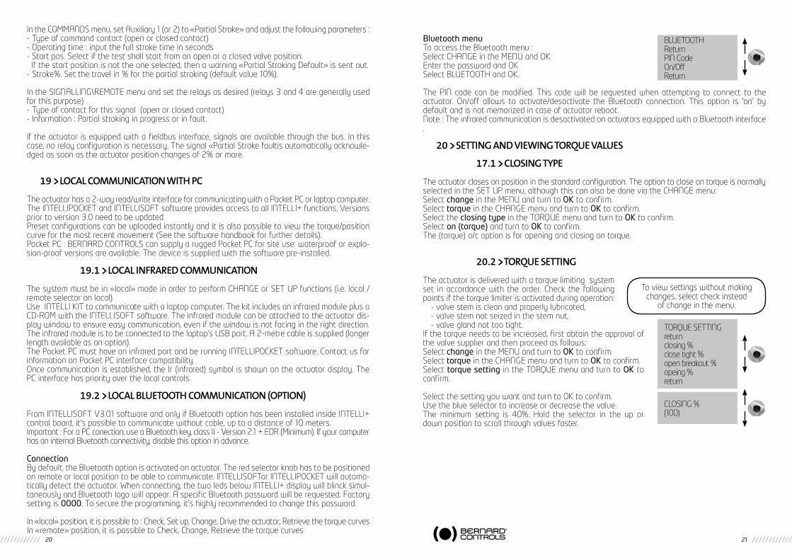
IntheCOMMANDSmenu,setAuxiliary1(or2)to«PartialStroke»andadjustthefollowingparameters:- Type of command contact (open or closed contact)- Operating time : input the full stroke time in seconds- Start pos. Select if the test shall start from an open or a closed valve position.Ifthestartpositionisnottheoneselected,thenawarning«PartialStrokingDefault»issentout.- Stroke%. Set the travel in % for the partial stroking (default value 10%).
IntheSIGNALLING\REMOTEmenuandsettherelaysasdesired(relays3and4aregenerallyusedfor this purpose)- Type of contact for this signal (open or closed contact)- Information : Partial stroking in progress or in fault.
If the actuator is equipped with a fieldbus interface, signals are available through the bus. In this case,norelayconfigurationisnecessary.Thesignal«PartialStrokefaultisautomaticallyacknowle-dged as soon as the actuator position changes of 2% or more.
19 LOCAL COMMUNICATION WITh PC
The actuator has a 2-way read/write interface for communicating with a Pocket PC or laptop computer. TheINTELLIPOCKETandINTELLISOFTsoftwareprovidesaccesstoallINTELLI+functions.Versionsprior to version 3.0 need to be updated.Preset configurations can be uploaded instantly and it is also possible to view the torque/position curve for the most recent movement (See the software handbook for further details).Pocket PC : BERNARD CONTROLS can supply a rugged Pocket PC for site use: waterproof or explo-sion-proof versions are available. The device is supplied with the software pre-installed.
19.1 LOCAL INFRARED COMMUNICATION
Thesystemmustbein«local»modeinordertoperformCHANGEorSETUPfunctions(i.e.local/remote selector on local). Use INTELLI KIT to communicate with a laptop computer. The kit includes an infrared module plus a CD-ROMwiththeINTELLISOFTsoftware.Theinfraredmodulecanbeattachedtotheactuatordis-play window to ensure easy communication, even if the window is not facing in the right direction. The infrared module is to be connected to the laptop’s USB port. A 2-metre cable is supplied (longer length available as an option).The Pocket PC must have an infrared port and be running INTELLIPOCKET software. Contact us for information on Pocket PC interface compatibility. Once communication is established, the Ir (infrared) symbol is shown on the actuator display. The PC interface has priority over the local controls.
19.2 LOCAL bLUETOOTh COMMUNICATION (OPTION)
FromINTELLISOFTV3.01softwareandonlyifBluetoothoptionhasbeeninstalledinsideINTELLI+control board, it’s possible to communicate without cable, up to a distance of 10 meters. Important:ForaPCconection,useaBluetoothkey,classII-Version2.1+EDR(Minimum).Ifyourcomputerhas an internal Bluetooth connectivity, disable this option in advance.
ConnectionBy default, the Bluetooth option is activated on actuator. The red selector knob has to be positioned on remote or local position to be able to communicate. INTELLISOFTor INTELLIPOCKET will automa-tically detect the actuator. When connecting, the two leds below INTELLI+ display will blinck simul-taneously and Bluetooth logo will appear. A specific Bluetooth password will be requested. Factory setting is 0000. To secure the programming, it’s highly recommended to change this password.
In«local»position,itispossibleto:Check,Setup,Change,Drivetheactuator,RetrievethetorquecurvesIn«remote»position,itispossibletoCheck,Change,Retrievethetorquecurves
Bluetooth menuTo access the Bluetooth menu :SelectCHANGEintheMENUandOKEnter the password and OKSelect BLUETOOTH and OK.
The PIN code can be modified. This code will be requested when attempting to connect to the actuator. On/off allows to activate/desactivate the Bluetooth connection. This option is ‘on’ by default and is not memorized in case of actuator reboot.Note : The infrared communication is desactivated on actuators equipped with a Bluetooth interface.
20 SETTING AND VIEWING TORQUE VALUES
17.1 CLOSING TYPE
The actuator closes on position in the standard configuration. The option to close on torque is normally selected in the SET UP menu, although this can also be done via the CHANGE menu:Select changeintheMENUandturntoOK to confirm.Select torque in the CHANGE menu and turn to OK to confirm.Select the closing type in the TORQUE menu and turn to OK to confirm.Select on (torque) and turn to OK to confirm.The (torque) o/c option is for opening and closing on torque.
20.2 TORQUE SETTING
The actuator is delivered with a torque limiting system set in accordance with the order. Check the following points if the torque limiter is activated during operation:
- valve stem is clean and properly lubricated,- valve stem not seized in the stem nut,- valve gland not too tight.
If the torque needs to be increased, first obtain the approval of the valve supplier and then proceed as follows:Select changeintheMENUandturntoOK to confirm.Select torque in the CHANGE menu and turn to OK to confirm.Select torque setting in the TORQUE menu and turn to OK to confirm.
Select the setting you want and turn to OK to confirm.Use the blue selector to increase or decrease the value. The minimum setting is 40%. Hold the selector in the up or down position to scroll through values faster.
BLUETOOTHReturnPIN CodeOn/OffReturn
To view settings without making changes, select check instead
of change in the menu.
TORQUE SETTINGreturnclosing %close tight %open breakout %opeing %return
CLOSING %(100)

22 23
Description of torque limit system:All torque values are expressed as percentages. 100% corresponds to the maximum setting for the actuator. This value is shown in Nm on the actuator nameplate.
- closing % : limits torque during closing- close tight %: this option is only displayed if closing is on torque limit. In this case, the torque applied on the valve seat may be not be the same as the torque limit during the closing movement.- open breakout %: this option is only displayed if closing is on torque. In this case, the torque limit to unseat the valve may be different from - generally higher than - the torque limit during the opening movement.
If the setting is above 100% the display shows no limitation (equivalent to override on the torque limiter at the start of the opening movement).
- opening %: limits torque during opening movement.
20.3 TORQUE READINGS AND COMPARISON WITh ORIGINAL TORQUE VALUES
Maximumresistive torquevaluesaremeasured forallmotorised movements and can be viewed later.Operating torque values for a movement can be stored in memory to allow comparison against torque values for the most recent motorised movement.Select changeintheMENUandturntoOK to confirm.Select torque in the CHANGE menu and turn to OK to confirm.Select measured torque in TORQUE menu, turn to OK to confirm.Select the torque value required and turn to OK to confirm.The display shows the maximum torque value measured during the most recent motorised movement. (note: movements are not measured when settings are being made)
If the torque values for a previous motorised movement have been stored in memory, these values can be viewed in the next line for reference.Example: in this example, the torque reading on the initial movement was12%andthetorqueonthemostrecentmovementis18%.The two values can be compared to determine whether any preventive maintenance is required.
Storing motorised movement torque valuesTosavetorquevaluesforamotorisedmovement,selectSAVEinthemenuandthenselect:torque => ref (yes).Reference torque readings take the torque values for the most recent motorised movement. If an error occurs, select: torque => ref (no) to restore the existing reference torque values.Values are only stored in memory when the user exits the CHANGE menu confirms (change ok?)
Displaying the position / torque curve for the most recent motorised movementSelect torque curve in the torque menu and turn to OK to confirm.Select open or close movement and then turn to OK to confirm.The curve is shown on the display screen with position from 0 to 100% and torque from 0 to 100% (100% is the maximum torque value on the actuator nameplate)
Note: Actuator settings must be made again after making changes to the tight torque setting (valves closing on torque)
Reminder: to save changes, exit menus by selecting return until the (change ok?) message is displayed
To view settings without making changes, select check instead
of change in the menu.
CLOSING%18ref.12
MEASUREDTORQUEreturnclosing %closing tight %open breakout %opening %savetorque displayreturn
SAVEtorque => ref (no)torque => ref (yes)
21 CUSTOMIZING STATUS AND CONTROL INDICATIONS
18.1 LOCAL INDICATION
The local display can be configured as follows:
Invert display: the display can be inverted (rotated 180 degrees). Select Change in the menu, then signaling, then local then invert display (yes).
Display torque: select this option to have the real-time torque value displayed on the actuator display at the same time as the position.Select Change in the menu, then signaling, then local then display torque (yes).
Red & Green LEDs: in the standard configuration, the red light indicates that the valve is closed and the green light means it is open. The assigned colours can be changes so that the red light indicates that the valve is open and the green one means it is closed.Select change in the menu, then signaling, then local then lights: Red=(open)To keep the valve open and valve closed labels in the correct position on the indicator, you must also open the cover with the window and turn round the display indicator plate.
21.2 REMOTE INDICATIONS
Signals giving actuator status data are transmitted via bistable relays. Each relay can be configured applying a list of available options.INTELLI+ has four bistable relays in the standard configuration. A further three bistable relays can be added as an option (the contact is open when there is no power).The equipment is configured at the factory in accordance with the order.
Changes can be made as follows:Select changeintheMENUandturnto OK to confirm.Select signaling in the CHANGE menu and turn to OK to confirm. Select remote in the SIGNALING menu and turn to OK to confirm.Select the relay in the SIGNALING menu and turn to OK to confirm.Choose contact type (i.e. activated contact status) and turn to OK to confirm.
Choose function or functions required:Several options can be selected for a single relay.When an option is selected, the brackets are removed and an asterisk * is displayed in front of the selected item. Turn to OK again to cancel selection.
LOC INDICATIONreturnopposite displaytorque displaylightsreturn
Torque 60%
RELAY 1(closed contact)(open contact)
RELAY 1return*valve open(closed valve)(torque limit open)(...)
REMOTEINDICATIONreturnrelay 1relay 2relay ...

24 25
Some of the selections have further options, see next page;
(1) (from x% to y%)Specify contact action range after turning to OK to confirm:Select x% and turn to OK to confirm.Use the blue selector to increase or decrease the value.Select y% and turn to OK to confirm.Use the blue selector to increase or decrease the value. Turn to OK to confirm.
(2) (running) (opening) (closing)
Turn to OK to confirm and then specify whether status to be steady or flashing indication. Turn to OK to confirm.
(3) (bus command)This function is only applicable if the fieldbus option is active. In this case, this relay can be used to control a device located outside the actuator, with commands transmitted from the control room via the fieldbus and then forwarded via the actuator (refer to documentation relating to bus).
FROMX%ANDY%returnx%y%return
X%(0)
Y%(100)
RUNNINGhold signalblinked
22 CUSTOMIZING FAULT RELAY
Fault signals are sent via a changeover relay which is normally energised and returns to the break position if power is lost or if the actuator is unavailable.This relay can be configured applying a list of options. The equipment is configured at the factory in accordance with the order. Changes can be made as follows:Select changeintheMENUandturntoOK to confirm Select signaling in the CHANGE menu and turn to OK to confirm.Select remote in the SIGNALING menu and turn to OK to confirm.Select fault relay in the SIGNALING menu and turn to OK to confirm.
Including additional faultsIncluded faults which cannot be altered are shown without brackets. Options are in brackets and selec-tions are shown with an asterisk *.Turn to OK again to cancel selection.
DEFAULT RELAYreturnpower offfusethermal overload...
List Detailspower offfusethermal overloadlost phasemotor blocked(jammed valve)* selector on local* selector on off(emergency command)(command override)(overtravel)(lost signal)
Detailsloss of power on control circuitblown fusethermal relay trippedphase missing on 3-phase supplymotor immobilisedmovement could not be completed due to excessive torquelocal / remote selector on locallocal / remote selector on offactuator has received an emergency commandactuator has received command overrideposition overshoot >5% after motor cut off.4-20 mA signal lost (if positioner option active)
Liste*valve open(valve closed)(torque limiter on opening)(torque limiter on closing)
(from x% to y%) (1)(selector on local)(selector on remote)(selector on off)(running) (2)(opening) (2)(closing) (2)(emergency command)(stop mid-travel)(power on)(thermal overload)(jammed valve)(lost phase)(lost signal)(handwheel action)(bus command)
(battery low)(p.t. in progress)(p.t. fault)
Detailsconfirms valve openconfirms valve closedtorque limiter active on opening torque limiter active on closing (indicates torque limiter action even if the valve is normally closed on torque limiter)intermediate travel indicationselector statusselector statusselector statusactuator in runningactuator performing opening actionactuator performing closing actionactuator has received an emergency commandactuator is halted (neither open nor closed)actuator powered normallymotor thermal relay trippedmovement could not be completed due to excessive torquephase missing on 3-phase supply4-20 mA signal lost (if positioner option active) handwheel has been used since last motorised movementif fieldbus option installed, this relay is assigned to an external command.If battery option used, the battery needs to be changedA “partial stroke” test is in progress.A partial stroke operating error has occurred following start of partial travel test, or it has not been possible to perform test as the valve was not in the expected position.

26 27
23 TIMING MOVEMENT TRAVEL
INTELLI+ includes a timing module for reducing the actuator’s operating speed (for example to protect a line against pressure surges).The timing system applies a series of on / off commands to the motor when an open or close command is transmitted. The time spent operating the valve can be very long. Times can be adjusted in situ.Settings for the opening and closing directions are separate.It is also possible to apply timing to just a section of the stroke, with the remainder being completed at normal speed.The user just has to specify the total time required for the movement and INTELLI+ calculates on and off times.
Select changeintheMENUandturntoOKtoconfirm.Select timer in the CHANGE menu and turn to OK to confirm.Select operating time and turn to OK to confirm.
Indicate time to perform movement at normal actuator speed. Use the blue selector to increase or decrease the value. Hold the selector in the up or down position to scroll through values faster. Turn to OK to confirm.
Select timer open time and turn to OK to confirm.Indicate the total time in which you want to open the valve and turn to OK to confirm.Select timer close time and turn to OK to confirm.Indicate the total time in which you want to close the valve and turn to OK to confirm.
To cancel the time function: check to ensure timer opening and closure times are not greater than travel time.
To apply timing to one part of travel only:select temporised zone and turn to OK to confirm.
To start opening timer from a specific position,select open: start % and turn to OK to confirm.Use the blue selector to increase or decrease the value until you obtain the required position between 0 and 100% and then turn to OK to confirm.Do the same for the other values to establish a timer-controlled opening zone and a timer-controlled closing zone.
Check default values when applying timer to entire stroke:open: start % (0) close: start % (100)open: end % (100) close: end % (0)
TIMERreturnoperating timetimer open timetimer close timetemporized zonereturn
OPERATINGTIME(0)
TIMEROPENTIME(0)
TEMPORIZEDZONEreturnopen : start %open : end %close : start %close : end %return
OPEN : START %(0)
24 VIEWING ACTUATOR hISTORY
21.1 ACTIVITY
Select changeintheMENUandturntoOK to confirm.Select activity in the CHANGE menu and turn to OK to confirm.Select number of starts or running time to view total figures since the actuator was manufactured. The system also includes a separate counter which can be reset by the user.Select total to view total number of starts.
To reset the partial counter, select reset partial and then choose yes or no (this option is only displayed when the user is in the change menu).
starts / 12 hour: this data relates to the number of times the actuator has started during the previous 12 hours and tells the user about recent service. This is particularly useful when trying to establish whether the actuator has been subjected to excessive use when performing modulating actions.
handwheel action: indicates whether the handwheel has been used since the last time a motorised movement was made. (changes are only registered if they exceed 10% of travel).
24.2 ALARMS
Alarms are used to pinpoint the source of malfunctions. They are not permanent and are deactivated when the fault is cleared. A blinking black square is shownon the screen to indicate that an alarm has been activated. To read alarms: Select checkintheMENUandturntoOKtoconfirm.Select alarms in the menu CHECK menu and turn to OK to confirm.Use the right-hand selector to scroll through any active alarms.
To check settings without makingchanges, select check instead
of change in the menu.
ACTIVITYreturnnumber of startsrunning timestarts last 12hhandwheel actionreturn
NUMBEROFSTARTStotalpartialreset partial
List Detailslocked motor openlocked motor closetorque sensorposition sensordirec of rot opendirec of rot closeovertravel config. memoryactivity memorybase memoryexcess starts
lost phaselost signalthermal overloadpumping24Vauxiliarybattery lowno alarm
DetailsMotorimmobilisedinopendirectionMotorimmobilisedinclosedirectionTorque sensor faultPosition sensor faultOpening direction of rotation anomalyClosing direction of rotation anomalyPosition overshoot >5% after motor cut off Stored configuration data errorStored activity data faultBase memory faultStart-up rate exceeds average for class of actuator.See criteria for class in §21This alarms never causes the actuator to stop operating.Phase missing on 3-phase supply4-20 mA signal lost (if positioner option active)MotorthermalswitchtrippedActuator hunting action detectedAuxiliary power supply fault for external circuits (terminals 6-7)If battery option used, the battery needs to be changed

28 29
25 ACCESSING DATA ShEET
Select changeintheMENUandturntoOK to confirm. Select data sheet in the CHANGE menu and turn to OK to confirm.
valve tag numberSelect valve tag number to read or write valve ID.Use the blue selector to change the first character and turn to OK to confirm.Change remaining characters using the same method.Turn to OK when all of the characters have been entered and continue until the menu is displayed again.
actuator number: this is the actuator’s serial number. This information is entered at the factory and is only shown in the CHECK menu.
entry code: for entering or changing a password, see below: “Creating or changing passwords”.characteristics: parameter settings for correct operation of the actuator (see details next page).
The following data is only shown in the CHECK menu.
operating class: indicates whether the actuator is designed for on/off operation, class III control or class II control functions. This item can be used to activate an alarm if the number of starts is excessive (excess. starts alarm).The number is the counted over the previous 12-hour period. Limits are as follows:On / Off: 360 starts in previous 12 hoursClass III: 1,200 starts in previous 12 hoursClass II: 21,600 starts in previous 12 hoursThis alarms never causes the actuator to stop operating.manufacture date: gives date product shipped from factory software version: installed software release
Characteristics menu details
motor : this data indicates whether the motor has a 3-phase, single phase or DCpower supply (data from manufacturer)protection: waterproof or explosion-proof version. The explosion-proof version prevents overriding the thermal relay in the degraded mode/commands menu.locked motor/s: Indicates the time the motor left energised when immobilised before power cut off. Default: 10 seconds (manufacturer’s data)reverse delay/ms: Indicates time actuator halted following change in direction of rotation. Default: 200 ms (manufacturer’s data).ratio position system: indication of gear stepdown ratio between output shaft and position sensor for displaying stroke in number of revolutions (or in degrees for fractions of a revolution) (manufactu-rer’s data).
To check settings without makingchanges, select check instead
of change in the menu.
DATA SHEETreturnvalve tag numberactuator numberentry codeoperating classmanufacture datecharacteriticssoftware versionreturn
VALVETAGNUMBERMOV55VV
CHARACTERITICSreturnmotorlocked motor/sreverse delay/msratio position systemext gear ratio 1/thread mmstrokereturn
external gear ratio 1/: indication of gear stepdown ratio for an additional gear. For example, for a quarter-turn gear with a ratio of 1:120, enter 120.Travel will then be indicated in degrees.thread in mm: Indication of pitch of a linear system to allow travel to be displayed in mm, rather than in number of revolutionsstroke: Indication of stroke value measured when adjusting valve.
26 CREATING OR ChANGING PASSWORD
Select changeintheMENUturntoOK to confirm.Select data sheet in the CHANGE menu and turn to OK to confirm.Select entry code in the DATA SHEET menu and turn to OK to confirm.Enter 1st digit with the blue button, then turn to OK to confirm.Enter 2nd digit with the blue button, then turn to OK to confirm.Enter 3rd digit with the blue button, then turn to OK to confirm.
The new code will not be taken into account until the user exits the change menu and confirms the change (change ok?)Makesureyoucanrememberthiscodetoaccessthechangemenuagain.
If you forget your codeSwitch off power to the system unit and open the control unity to access theINTELLI+board(supportingthedisplay).Movethejumperontheboardfrom position A to position B, then turn the power back on. The password has now been reset to zero. Place the jumper back in its original position (A).If you leave the jumper in position B, you will still be able to enter a new password, but it will be reset to zero the next time you switch the unit on.
27 USING ANALOGUE POSITION SIGNAL (DEPENDING ON MODEL)
On some models, the actuator can use an analogue signal to transmit its percentage position (0 - 100%) to a remote device.The output signals are automatically calibrated on the actuator’s stroke (0 - 100%) and so the trans-mitted position signal does not need any adjustment.
The transmitted signals are totally isolated from the INTELLI+ circuits.Usea rectified, filteredor stabilised 12 -32VDCpower supply for this position signal. It is also possible tousetheinternal24Vpowersupplyonterminals6(-)and7(+).Max.permissibleloadingisshownonthetable.
The following signals can be used:4-20 mA, 0-20 mA, 4-12 mA or 12-20 mA.4-20 mA, 4-12 mA or 12-20 mA outputs can connected with two wires, with the external power supply in series with the signal reading. (see actuator circuit diagram)The0-20mAoutputcanbeusedtoobtaina0-10Vsignal using an external 500 ohm (or 499 ohm 1%) resistor.Thepowersupplyvoltagewillbe15to32V.
ENTRY CODE(000)
CAV
BA
jumper
Power supply (volts)
Max. permissible load (ohms)
12 150
34 750
30 1050
32
33
34
35
0-10V position remote signal
15 - 32V
+
-
+
-0-10V500
Ohm

30 31
To select the signals’ direction of variation and typeSelect changeintheMENUandturntoOK to confirm.Select position in the CHANGE menu and turn to OK to confirm.Select opt. posit. signal in the POSITION menu and turn to OK to confirm.Choose signal’s direction of variation and turn to OK to confirm.Select signal type and turn to OK to confirm.
28 USE AS A POSITIONER WITh AN ANALOGUE CONTROL SIGNAL (DEPENDING ON MODEL)
28.1 INPUT SIGNAL
On some models, the actuator can operate as a positioner using a proportional command, such as a 4-20 mA analogue signal.The input signal is automatically calibrated on the actuator’s stroke (0 - 100%) and so there is no need to adjust the actuator’s operating range. The input signal is isolated from the on/off commands and from the remote position signal.The actuator can still be operated in on/off mode with the open, close and stopcommands or using proportional control. One of the auxiliary commands must be used to select between these two control modes.In the standard configuration, auxiliary command is set for AUTO / ON-OFF to allow the control mode to be selected remotely: AUTO = proportional control (analogue) or ONOFF= on/off control. See section 15.2 for configuration details and informa-tion on using this command.
Control signal4-20mA,0-20mA,4-12mA,12-20mAor0-10VTo select the signals’ direction of variation and type:Select changeintheMENUandturntoOK to confirm.Select positioner in the CHANGE menu and turn to OK to confirm.Select signal type in the POSITIONER menu and turn to OK to confirm.Choose signal’s direction of variation and turn to OK to confirm.Choose signal type and turn to OK to confirm.
With 0-10 V signals, two contacts are also switched to OFF. The contacts are located on the INTELLI+ board (supporting the display) inside the control unit.
OPT POSIT SIGNALsignal ( ) openingsignal ( ) opening
SIGNAL ( ) OPENING(4-20 mA)(0-20mA)/(0-10V)(4-12 mA)(12-20 mA)
Signal Input impedance (Ohms)
4-20 mA 160
0-20mA 160
4-12mA 160
12-20mA 160
0-10V 11000
30
31
-
+
4 - 20 mA0 - 20 mA0 - 10 V
SIGNAL RANGELsignal ( ) openingsignal ( ) opening
SIGNAL ( ) OPENING(4-20 mA)(0-20mA)/(0-10V)(4-12 mA)(12-20 mA)
A
B
ON mA
Volt
51
28.2 SETTING OF DEADbAND VALUE
The deadband value is the maximum allowable difference between the signal and the actuator position when no action occurs.This setting is made at the factory, but it is possible to adjust it.If the deadband is too narrow, the actuator could start hunting, i.e opening and closing around the expected position without being able to stabilise. If the deadband is too wide, positioning actions are less precise.The default deadband setting is 1%.Select dead band % in the POSITIONER menu and turn to OK to confirm.Use the blue selector to increase or decrease the value. Turn to OK to confirm.
28.3 FAIL-SAFE POSITION
When a 4-20 mA input signal is used, it is possible to set up a fail-safe position for use if the control signal is lost. Caution: this function cannot be used with 0-20 mA signals, as the system cannot distinguish between a lost signal and a 0 mA value.This function is active in the standard configuration, and the actuator remains in position if the signal is lost.The user can also choose open or close. Select lost signal in the POSITIONER menu and turn to OK to confirm. Select the action required and turn to OK to confirm.
28.4 PROPORTIONAL PULSE MODE
INTELLI+ incorporates a positioning mode which takes account of the actuator’s inertia. If the move-ment time is too short or if the motor has excessive inertia, positioning can be improved by selecting proportional pulse mode. INTELLI+ calculates and corrects the motor’s stopping point to reach the expected position and then applies pulses proportional to any deviation if necessary.This mode is used for relatively stable control actions where partial compensation can be made the actuator’s inertia. The actuator is cycled more often than with a standard command.Select proportional pulse in the POSITIONER menu and turn to OK to confirm. Select (no) or (yes) and turn to OK to confirm.
29 USING FIELDbUS CONTROL (DEPENDING ON MODEL)
The fieldbus interface is used for sending commands and data over a single line. Specific docu-mentation details methods for addressing individual actuator and provides a list of addresses for accessing all commands or data sources.The type of interface is shown in the menu.Lost communication can be used to configure the fail-safe po-sition. This function is active in the standard configuration, and the actuator remains in position if communication is lost.The user can also choose open or close.Select changeintheMENUandturntoOKtoconfirmSelect bus in the CHANGE menu and turn to OK to confirm.Select lost communication in the BUS menu and turn to OK to confirm.Select the action required and turn to OK to confirm.
LOST SIGNAL(closing(stayput)(opening)
PROFIBUSreturnlost communicationCmd by flieldbusslave numberreturn
LOSTCOMMUNIC(closing)(stayput)(opening)
32 33
Bus control: Bus control is normally selected. For equipment which also uses a standard hard-wired system, this configuration allows the user to chose the command mode: either via bus or hard-wired (see §6.1 and §6.2)
Slave no. Actuator address. All actuators have to have different addresses.The default address is 2.Refer to specific documentation for further details on fieldbus interfaces commissionning.
30 USING IN CASE OF POWER SUPPLY LOST (WITh bATTERY DEPENDING ON MODEL)
Depending on the actuator model, the battery option allows to display the position when the power supply is off. When the power supply is off, the actuator goes into standby mode with very low power consumption.
Regular tests allow to check the valve position, if the position changed the relays are updated.
- In case of actuator with position feedback the position is updated.
- In case of fieldbus communication, the fieldbus board is supplied (5s) to allow the PLC bus controller to read the new position.
When the power supply is off the display can be read but it cannot possible to navigate into the menu.To wake up the system and illuminate the display, you must act on the command button blue as to give an order to close. The “low battery” information can be read at any time on the display or by remote signalling. The display will be shut down after 30 secondes without activity.
- Battery estimated life time in the actuators: 1/3 of time in storage or without power supply (Includes display of 20 s / day during this period) 2/3 of time with power supply- Temperature: 40°C (For different temperatures (above or below) the life expectancy may be reduced)- Battery life time: 10 years.
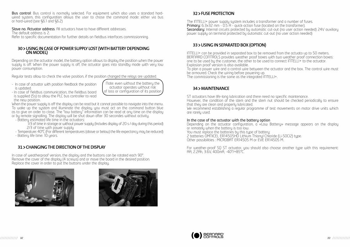
31 ChANGING ThE DIRECTION OF ThE DISPLAY
In case of weatherproof version, the display and the buttons can be rotated each 90°.Remove the cover of the display (4 screws) and or move the board in the desired position.Replace the cover in order to put the buttons under the display.
Note: even without the battery theactuator operates without risk
of loss or configuration of its position
32 FUSE PROTECTION
The INTELLI+ power supply system includes a transformer and a number of fuses.Primary: 6.3x32 mm - 0.5 A - quick-action fuse (located on the transformer).Secondary:Internalcircuitsprotectedbyautomaticcut-out(nouseractionneeded)24Vauxiliarypower supply on terminal protected by automatic cut-out (no user action needed)
33 USING IN SEPARATED bOx (OPTION)
INTELLI+ can be provided in separated box to be removed from the actuato up to 50 meters. BERNARD CONTROLS provides weather proof boxes with two weather proof connection boxes: one to be used by the customer, the other to be used to connect INTELLI+ to the actuator.Explosion proof version is also available.To plan a power wire and a control wire between the actuator and the box. The control wire must be armoured. Check the wiring before powering up.The commissioning is the same as the integrated INTELLI+.
34 MAINTENANCE
ST actuators have life-long lubrication and there need no specific maintenance.However, the condition of the stem and the stem nut should be checked periodically to ensure that they are clean and properly lubricated.We recommend establishing a regular programme of test movements on motor drive units which are rarely used.
In the case of the actuator with the battery optionDepending on the actuator configuration, a «Low Battery» message appears on the display or remotely when the battery is too low.You must replace the batteries by this type of battery:2batteriesOMNICELER14505HDLithiumThionylChloride(Li-SOCl2)type.Otherpossibilities:MICROBATER14505MorEVEER14505M.
For weather-proof SQ ST actuator, you should also choose another type with this requirement: AA,2.2Ah,3.6V,400mA,-40°/+85°C.

34 35
PRO
BLE
MCA
USE
REM
EDY
The
actu
ator
rota
tes
in t
he w
rong
di
rect
ion
Inco
rrect
con
figur
atio
nCh
eck
clos
ing
dire
ctio
n in
the
posi
tion
sub-
men
u un
der c
hang
e to
det
erm
ine
whe
ther
clo
sing
act
ion
cloc
kwis
e or
ant
i-clo
ckw
ise.
.
Mot
orw
iring
cha
nged
and
mot
or
rota
tes
in re
vers
e di
rect
ion
(whe
n m
otor
repl
aced
)
Com
ply
with
wiri
ng t
ags
whe
n ch
angi
ng t
he m
otor
. If i
n do
ubt,
chec
k m
otor
rota
tes
the
right
w
ay. T
he m
otor
’s d
irect
ion
of ro
tatio
n ca
n be
reve
rsed
by
chan
ging
ove
r wire
s 2
and
3 on
the
m
otor
term
inal
str
ip in
side
the
con
trol
box
.
Men
use
ttings
can
notbe
cha
nged
Chan
ges
cann
ot b
e m
ade
in th
e ch
eck
men
uGo
to
the
chan
ge m
enu.
So
me
sett
ings
are
vie
w-o
nly.
The
actu
ator
ope
rate
s in
loca
l m
ode,
but
not
in re
mot
e.Lo
cal /
rem
ote
sele
ctor
on
rem
ote
or o
ff (s
top)
Switc
h th
e lo
cal /
rem
ote
sele
ctor
to
the
loca
l pos
ition
.
Dry
con
tact
con
trol
: no
volta
ge
betw
een
term
inals6
and
7En
sure
ther
e is
a ju
mpe
r bet
wee
n te
rmin
als
5 an
d 6
on th
e cl
ient
term
inal
str
ip.
Chec
kwhe
ther
a“2
4Vaux
iliary
”alarm
ispre
sent
Volta
gecon
trol:v
olta
gen
ot
adap
ted
to in
put
Chec
k vo
ltage
con
trol
con
nect
ions
: 10
- 5
5 vo
lts: t
erm
inal
5
55 t
o 25
0 vo
lts: t
erm
inal
4
Chan
ges
mad
e no
t ap
plie
d.N
o m
odifi
catio
ns m
ade
durin
g ch
ange
pro
cess
.Ch
ange
s ha
ve t
o be
con
firm
ed
befo
re t
hey
are
save
d
Aft
er m
akin
g ch
ange
s, ru
n ba
ck t
hrou
gh t
he m
enus
usi
ng re
turn
and
OK
until
the
dis
play
sho
ws:
(c
hang
e ok
?)Tu
rn to
OK
to c
onfir
m a
nd s
ave
the
chan
ges
mad
e
Act
uato
r jer
ky o
pera
tion
durin
g m
ovem
ent
Tim
ing
func
tion
sett
ings
mad
eTh
e us
er s
ets
this
opt
ion
in t
he t
imer
men
u to
incr
ease
the
act
uato
r’s m
ovem
ent
time.
Han
dwhe
el a
ctio
n no
t de
tect
edH
andw
heel
act
ion
dete
cted
sin
ce
last
mot
oriz
ed m
ovem
ent p
rovi
ded
actu
ator
rem
ains
sw
itche
d on
. The
sy
stem
onl
y re
port
s m
ovem
ents
ex
ceed
ing
10%
of t
rave
Repe
at d
etec
tion
unde
r cor
rect
con
ditio
ns.
Exce
ss s
tart
s al
arm
disp
laye
dIN
TELL
I+ m
onito
rs th
e nu
mbe
r of
sta
rts p
erfo
rmed
dur
ing
the
prev
ious
12
hour
s an
d ch
ecks
thi
s nu
mbe
r aga
inst
the
act
uato
r’s
oper
atin
g cl
ass.
This
ala
rm d
oes
not
rest
rict
oper
atio
n of
the
act
uato
r. It
just
indi
cate
s th
at t
he a
ctua
tor i
s be
ing
used
inte
nsiv
ely.
The
ala
rm w
ill c
lear
ed w
hen
the
num
ber o
f sta
rts
retu
rns
to t
he in
tend
ed
freq
uenc
y fo
r the
sys
tem
con
cern
ed.
PRO
BLE
MCA
USE
REM
EDY
The
disp
lay
is o
ffA
ctua
tor p
ower
sup
ply
Chec
k po
wer
sup
ply
volta
ge (t
erm
inal
s L1
, L2
and
L3 fo
r 3-p
hase
sup
ply)
.Th
e vo
ltage
val
ue is
sho
wn
on th
e na
mep
late
.
Blow
n fu
seCh
eck
fuse
and
repl
ace
if re
quire
d (th
e fu
se is
fitt
ed o
n th
e tra
nsfo
rmer
).
No
resp
onse
Dis
play
in m
enu
mod
eSe
t loc
al /
rem
ote
sele
ctor
to o
ff an
d th
en o
n lo
cal t
o ch
ange
to c
omm
and
mod
e (d
ispl
ay: %
posi
tion)
IR li
nk a
ctiv
eCo
mm
ands
can
not b
e m
ade
usin
g th
e se
lect
ors
if an
IR li
nk is
act
ive
(IR
sym
bol o
n th
e di
spla
y). T
urn
off t
he in
frare
d lin
k.
Mot
orth
ermalswitc
htrip
A b
lack
squ
are
is s
how
n at
the
bott
om c
entre
of t
he d
ispl
ay to
indi
cate
that
an
ala
rm h
as b
een
activ
ated
. Go
to m
enu
/ che
ck /
alar
ms
to s
ee w
heth
er a
m
otor
ove
rhea
ting
alar
m is
pre
sent
.Th
e ac
tuat
or w
ill be
ava
ilabl
e ag
ain
whe
n th
e m
otor
has
coo
led
dow
n
No
resp
onse
and
the
key
or E
SD
sym
bol i
s di
spla
yed
Loca
l com
man
d ov
errid
e or
ESD
co
mm
and
activ
eCh
eck
Aux
. com
man
d 1
or 2
opt
ions
in th
e co
mm
and
men
u to
see
whe
ther
a
com
man
d ov
errid
e or
em
erge
ncy
com
man
d ha
s be
en s
et u
p an
d ch
eck
the
stat
us (o
pen/
clos
ed) o
f the
con
tact
use
d to
per
form
this
rem
ote
com
man
d.Th
en c
heck
the
conn
ectio
n on
the
clie
nt te
rmin
al to
see
whe
ther
it c
orre
s-po
nds
to a
com
man
d ov
errid
e or
em
erge
ncy
com
man
d.Fo
r exa
mpl
e, if
the
confi
gura
tion
sett
ing
is o
n au
x. c
omm
and
1, lo
c cm
d
inhi
bit a
nd c
onta
ct (o
)= in
hibi
t, a
rem
ote
cont
act w
ill ha
ve to
be
esta
blis
hed
on te
rmin
al 1
1 to
can
cel t
he o
verri
de.
The
actu
ator
ope
rate
s in
rem
ote
mod
e, b
ut n
ot in
loca
lLo
cal /
rem
ote
sele
ctor
on
rem
ote
or o
ff (s
top)
Switc
h th
e lo
cal /
rem
ote
sele
ctor
to th
e lo
cal p
ositi
on.
Loca
l com
man
d ov
errid
e ac
tive
(key
sy
mbo
l dis
play
ed) o
r loc
al /r
emot
e se
lect
ion
perfo
rmed
rem
otel
y
Chec
k A
ux. c
omm
and
1 or
2 o
ptio
ns in
the
com
man
d m
enu
to s
ee w
heth
er
a co
mm
and
over
ride
has
been
set
up
and
chec
k th
e st
atus
(ope
n/cl
osed
) of
the
cont
act u
sed
to p
erfo
rm th
is re
mot
e co
mm
and.
Th
en c
heck
the
conn
ectio
n on
the
clie
nt te
rmin
al to
see
whe
ther
it c
orre
s-po
nds
to a
com
man
d ov
errid
e.
For e
xam
ple,
if th
e co
nfigu
ratio
n se
ttin
g is
on
aux.
com
man
d 1,
loc
cmd
inhi
bit
and
cont
act (
o)=
inhi
bit,
a re
mot
e co
ntac
t will
have
to b
e es
tabl
ishe
d on
te
rmin
al 1
1 to
can
cel t
he o
verri
de.
Men
uca
nnot
be
acce
ssed
Sele
ctor
on
rem
ote
or o
ff, o
r loc
al
com
man
d ov
errid
e ac
tive
The
men
u ca
n on
ly b
e ac
cess
ed v
ia t
he s
elec
tors
in lo
cal m
ode,
i.e.
with
th
e se
lect
or o
n lo
cal a
nd n
o ov
errid
e on
loca
l con
trol
. Set
the
sel
ecto
r on
loca
l and
car
ry o
ut c
heck
s on
aux
. com
man
ds 1
& 2
indi
cate
d ab
ove.
35 TROUbLEShOOTING
If there is any doubt about the operation of the system, first set the local / remote selector in the local position and then operate the open and close controls.

36 37
All SQ/ST intelli+ models can be connected following this diagram. Internal structure is different on SQ6/SQ15 (see diagram S640040/00). Tous les actionneurs SQ/ST utilisent les mêmes repères. L’organisation interne des actionneurs SQ6/SQ15 est différente (Voir schéma S640040/00).MA, MB, MAS & MBS are using solid state relays / sont équipés de relais statiques

38 39
1 SéCURITé
Cet appareil répond aux normes de sécurité en vigueur. Toutefois, seule une installation, une maintenance et une utilisation effectuées par un personnel qualifié et formé permettront d’assurer un niveau de sécurité adéquat.
Lors des montage et démarrage, suivre attentivement les instructions de cette notice.
2 PRéSENTATION
Bouton bleu ouverture, fermeture et flèches pourse déplacer dans le menu
affichage
Liaison infrarouge
Voyantsvanneouverte et fermée
Bouton rouge local/distance/stop
et validation OK du menu
Quart de tour+ Boitier FPi Multitour + Boitier FPi
ST175 & ST220 MultitourCombi quart de tour+ Boitier FPi
1 Sécurité Page 392 Présentation Page 393 Stockage Page 404 Commande manuelle et débrayage Page 405 Montage Page 416 Réglage des butées mécaniques (Gamme SQ) Page 417 Raccordement electrique Page 428 Principe du réglage sur vanne Page 429 Commande a distance Page 4310 Commande locale par boutons Page 4411 Comment naviguer dans les menus Page 4412 Sélectionner la langue d’affichage Page 4613 Mot de passe Page 4614 Organigramme du menu consulter Page 4715 Organigramme du menu régler et modifier Page 4816 Comment régler un servomoteur sur une vanne Page 4917 Recopie et positionneur Page 5018 Commandes Page 5119 Communication locale par PC Page 5520 Comment régler et lire les couples Page 5621 Comment personnaliser les signalisations Page 5822 Comment personnaliser le relais defaut Page 6023 Comment temporiser en cours de manoeuvre Page 6124 Comment voir l’activité du servomoteur Page 6225 Comment accéder a la fiche technique Page 6326 Comment créer ou modifier le mot de passe Page 6427 Utilisation du signal analogique de recopie de position (suivant équipement) Page 6428 Utilisation en positionneur a partir d’un signal de commande analogique (suivant équipement) Page 6529 Utilisation du controle par bus de terrain (suivant équipement) Page 6630 Utilisation hors tension (avec pile suivant équipement) Page 6731 Comment changer l’orientation de l’afficheur Page 6832 Protection fusibles Page 6833 Utilisation en coffret séparé Page 6834 Entretien Page 6835 Anomalie de fonctionnement Page 6936 Schéma multi-options (Câblage interne différent sur SQ6 / SQ15) Page 36
SOMMAIRE

40 41
3 STOCKAGE
IntroductionUn servomoteur est composé d’éléments électriques et d’une partie mécanique lubrifiée à la graisse. Malgré l’étanchéitéde l’enveloppedecetensemble, les risquesd’oxydation,degommageetdegrippage peuvent apparaître lors de la mise en service du servomoteur si son stockage n’a pas été correctement réalisé.
StockageLes servomoteurs doivent être stockés sous abri dans un endroit propre et sec et protégé des chan-gements successifs de température.Eviter le stockage à même le sol. Dans le cas de présence d’humidité alimenter le servomoteur pourpermettrel’actiondelarésistancedechauffage.Vérifierquelesentréesdecâblesontbienétanches. En cas de présence d’humidité, remplacer ceux-ci par des bouchons filetés métalliques.S’assurer de la bonne étanchéité des couvercles, des boîtiers renfermant les éléments électriques.Dans le cas de vanne dont la levée de tige est importante, vérifier que le capot de protection estbienmontésurleservomoteur.Sinon,montercelui-ciavecunepâteàjoint.
Contrôle après stockage
1. Durée du stockage inférieure à 1 an • Contrôle visuel de l’équipement électrique. • Procéder à quelques manoeuvres manuelles. • Vérifierlabonneconsistancedelagraisse. • Procéder à la mise en service du servomoteur.
2. Durée du stockage supérieure à 1 an • Le stockage à long terme entraîne un changement dans la consistance de la graisse.
En faible épaisseur sur les axes ou tourillons elle se dessèche. Il est donc nécessaire de procéder à quelques rotations plusieurs fois par an (par démarrage moteur ou à l’aide du volant) pour prévenir tout problème.
• Contrôle visuel de l’équipement électrique. • Pour les actionneurs équipés de l’option batterie. Durant le stockage, le circuit est en
fonctionnement basse consommation et permet un longue durée de conservation de la batterie. Néanmoins, au délà de 3 ans de stokage, il est préférable de remplacer la batterie lors de la mise en service. A tout moment, il est possible de vérifier l’état de la batterie sur l’afficheur.
4 COMMANDE MANUELLE ET DEbRAYAGE
Les servomoteurs équipés de l’INTELLI+ sont tous équipés d’une commande manuelle. Le sens de manoeuvre est normalement indiqué sur le volant.
Modèles SQ6 et SQ15 :Ils sont équipés d’une commande manuelle débrayable manuellement.Pour passer en mode manuel, il faut tourner le volant tout en tirant dessus afin de l’engager mécaniquement (Fig. 1).Le débrayage du volant s’effectue en le repoussant en butée vers le carter.
(fig 1)
Modèles SQ20 à SQ80 :Afin de faciliter la manoeuvre manuelle, certains de ces modèles sont équipés d’un levier de débrayage du moteur monté sur un étage de réduction intermédiaire. En fin de manoeuvre ma-nuelle, ne pas oublier de réembrayer le moteur. Sinon, celui-ci tournera à vide jusqu’à l’activation de la protection thermique. Si cet incident se répète, un risque de détérioration du moteur existe.
Modèles SQ100 à SQ100, et ST6 :Les servomoteurs SQ100 à SQ1000 et ST6 possèdent une poignée d’embrayage du volant. Pour passer en mode manuel, aligner la flèche de la poignée d’embrayage avec le repère triangulaire (Fig. 2) situé sur le carter (il peut être nécessaire de tourner le volant de quelques degrés pour dégager les crabots). Le passage en mode électrique s’effectue automatiquement au démarrage du moteur, ou bien manuellement si on le désire.
Tous modèles ST (sauf ST6)Tous les actionneurs de la gamme ST (sauf ST6) sont équipés d’un système d’embrayage auto-matique du volant par différentiel donnant toujours priorité au moteur. Le sens de manoeurvre est généralement indiqué sur le volant.
5 MONTAGE
Le servomoteur doit être boulonné sur l’appareil à motoriser.Les servomoteurs BERNARD CONTROLS sont graissés à vie et peuvent fonctionner dans n’importe quelle position. Cependant, les presse-étoupes ne devraient idéalement pas être orientés vers le haut (étanchéité) et le moteur pas placé en position basse (condensation d’eau interne potentielle).
Note 1: ne pas transporter les servomoteurs par le volant sous peine d’endommager le couple roue et vis.Note 2: voir les précautions de stockage avant mise en route.Note 3: En cas de montage sur vanne à tige montante, vérifier le graissage de l’écrou en bronze
de la forme A avant montage sur vanne.
6 RéGLAGE DES bUTéES MECANIQUES (GAMME SQ)
Description et fonction des butées mécaniques (SQ uniquement) Ce dispositif limite mécaniquement la course lors de la manoeuvre de la vanne et de ce fait évite tout déréglage. Suivant les cas, les butées sont localisées sur le servomoteur ou sur le réducteur 1/4 Tour.Les servomoteurs sont réglés en usine pour une rotation de 90°. Un réglageestpossiblegrâceauxvisd’arrêtdanslalimitede2°àchaqueextrémité.
(fig 2)
(fig 3)
ATTENTIONDans le cas de servomoteurs quart de tour, des butées, localisées sur le servomoteur
ou sur le réducteur, limitent mécaniquement la course lors de la commande manuelle de la vanne. Il faudra impérativement veiller à ce que le servomoteur, lors des manoeuvres électriques d’ouverture ou de fermeture s’arrête avant d’atteindre ces butées mécaniques

42 43
7 RACCORDEMENT ELECTRIQUE
Seul le capot de la boite de raccordement sera ouvert le temps du raccordement électrique. Les autres capots ne doivent pas être ôtés au risque d’introduire de l’humidité dans les systèmes decontrôle.Unschémadecâblageestfourniavecl’actionneur.Si ce n’est pas le cas, le demander à notre service client.
Mode opératoirea) Vérifierlanatureetlatensionducourantparrapportàla
plaque signalétique. Le sens des phases en triphasé n’est pas important, L’INTELLI+ corrige automatiquement le sens.
b) Ouvrir la boite de raccordement (fig. 4), raccorder puis-sance et contrôle (cosses à oeillet non fournies). Le dia-mètre des vis fournies est de 3mm pour le contrôle et 4 mm pour la puissance
c) Vérifier le câblage et le bon positionnement du jointd’étanchéité du couvercle.
d) Vérifier que les vis du couvercle ainsi que les presse-étoupeontbienétéresserrésaprèscâblage.
Spécifications de raccordement pour SQ6 & SQ15Sur les appareils SQ6 et SQ15 Intelli+, il est nécessaire de faire un blindage à l’aide de presse-étoupe à raccordement de masse.Poursefaire,ilfaututiliseruncâbleblindéetréaliserlemontage suivant pour la partie commande :
a) Dénuderlecâbleb)Passezlecâbledanslepresseétoupec) Repliez le blindage pour le mettre en contact avec
l’intérieur du presse-étoupeUn fusible rapide doit être installé sur l’alimentation du servo-moteur. Le fusible, non fourni par Bernard Controls, peut être placé à l’intérieur ou l’extérieur de la boîte de raccordement.
1x230VAC50Hz......................................... :6,3x32mm1A1x115VAC60Hz............................................:6,3x32mm1.8A3x400/460VAC50Hz............................. :6,3x32mm0,5A1x24VAC50-60Hz.................................... :6,3x32mm10A
8 PRINCIPE DU RéGLAGE SUR VANNE
Chaque servomoteur équipé de l’INTELLI+ est configuré et contrôlé en usine avant expédition.Si le servomoteur est livré déjà monté sur une vanne, les positions ouvertes et fermées ainsi que les valeurs de couple maximum ont, en principe, été réglées par le robinetier en usine.Si un réglage sur vanne doit être effectué ou retouché, celui-ci peut être effectué avec la seule alimen-tation de puissance électrique raccordée. Tous les réglages et configurations se font ensuite, de l’exté-rieur, de manière non-intrusive, à l’aide des boutons rotatifs bleu et rouge et de l’afficheur graphique.
La lecture des chapitres suivants permet d’acquérir les connaissances nécessaires au réglage du servomoteur sur vanne :
§11.COMMENTNAVIGUERDANSLESMENUS§12. SELECTIONNER LA LANGUE D’AFFICHAGE§20.COMMENTREGLERETLIRELESCOUPLES(encasdefermeturesurcouple)
§20.1 Type de fermeture§20.2 Réglage du couple
§16.COMMENTREGLERUNSERVOMOTEURSURUNEVANNE
9 COMMANDE A DISTANCE
La commande à distance des servomoteurs INTELLI+ peut être réalisée à partir d’une alimentation externe, ou d’une alimentation intégrée.Le circuit d’entrée est totalement isolé par des optocoupleurs. La commande impulsionnelle (avec automaintien) nécessite 4 fils de liaison sur le bornier client : commun, stop, ouverture et fermeture. Si le bouton poussoir arrêt n’est pas utilisé, ne pas raccorder la liaison STOP, le contact ouverture (ou fermeture) doit être maintenu pour actionner le servomoteur.
9.1 COMMANDE PAR CONTACT
En commande par contact, il est nécessaire de faire un shunt aux bornes client 5-6.
9.2 COMMANDE PAR TENSION
La commande à distance peut s’effectuer indifféremment en courant continu ou en courant alternatif.Pourlestensionsbassesde10à55V,utiliserlecommunborne5.Pourlestensionshautesde55à250V,utiliserlecommunborne4.
Attention : ne jamais raccorder une source de tensionsupérieure à 55V sur le commun borne 5
24V
1,2W
-
+
4
5
6
7
8
9
10
STOP
FERM
OUV
Commande à distanceimpulsionnelle (auto maintien)
24V
1,2W
-
+
4
5
6
7
8
9
10
FERM
OUV
Commande à distancesans auto maintien
4
5
6
7
8
9
10
FERM
OUV
Pour supprimer l'automaintien,ne pas raccorder la borne 8.
10 - 55V ~ 4
5
6
7
8
9
10
FERM
OUV
55 - 250V ~
STOPSTOP

44 45
10 COMMANDE LOCALE PAR bOUTONS
Une commande locale par boutons est disponible sur le servomoteur. Le bouton rouge permet de choisir la commande distance (remote), local, ou condamné (off). Le bouton rouge peut être verrouillé avec un cadenas de diamètre 6mm dans les 3 positions.Le bouton de commande locale (bleu) ouverture et fermeture permet de manoeuvrer le servomoteur dans le sens désiré.Le stop local s’effectue par une rotation momentanée du bouton rouge local/ distance.
En position intermédiaire l’affichage indique la position de la vanne en % d’ouverture.Vanne fermée l’afficheur indique «fermé»Vanne ouverte l’afficheur indique «ouvert»Suivant la configuration, l’afficheur peut indiquer le couple de manoeuvre instantané en % du couple maxi du servomoteur.En dessous de 10%, l’affichage indique < 10%.
Symboles pouvant apparaitre sur l’afficheur :
Leservomoteurreçoituneinterdictiondecommandelocale(voir§18.2)Leservomoteurreçoitunecommanded’urgence(voir§18.2)Une liaison infrarouge est détectée (voir §19)UneliaisonBluetoothestdétectée(OptionalternativeàlaliaisonIR.Voir§19)Ce sigle indique la présence d’une alarme. (voir §24.2 pour lire le type d’alarme)Dans le cas d’une option pile, l’icône clignote si la tension de la pile est faible.0% Cette icône indique que la commande est proportionnelle et la valeur du signal d’entrée est indiquée en %.Le sigle BUS indique la présence d’une carte de communication par bus. Le sigle est suivi d’un carré permettant de connaitre l’état de la communication (voir doc. spécifique du bus installé).1 et 2 indiquent la présence d’une carte de communication par bus redondant (2 voies de communication). Le chiffre est suivi d’un carré permettant de connaitre l’état de chaque voie de communication (voir doc. spécifique du bus installé).
11 COMMENT NAVIGUER DANS LES MENUS
La commande par boutons utilisée pour la manoeuvre électrique du servomoteur est aussi le moyen pour naviguer dans les menus et accéder aux fonctions de l’INTELLI+.
11.1 PRéSENTATION DES bOUTONS
Bouton bleu (à droite)- sélection de choix
Bouton rouge (à gauche)- position sur OK : confirmation de choix- position sur OFF : sortir du menu à tout moment
20% Ouvert
Fermé
Ouvert
Couple 60%
ESDIR
1 2
0%
BUS
ESDIR
1 2
0%
BUS
ESDIR
1 2
0%
BUS
ESDIR
1 2
0%
BUS
ESDIR
1 2
0%
BUS
ESD
0%
BUS
1 2
ESD
0%
BUS
1 2
ESDIR
1 2
0%
BUS
11.2 ACCéDER AU MENU PRINCIPAL
- Mettreleboutonrougesurlocal- Tourner et maintenir le bouton rouge sur stop local et en même temps tourner le bouton bleu
vers le haut puis vers le bas. Le menu principal s’affiche :
- Relâcherleboutonrouge,ilseplacedevant“local”.
Pour lire les rubriques du menu tourner le bouton bleu vers le haut ou vers le bas.
11.3 SéLECTIONNER UN MENU OU UNE RUbRIQUE
Sélectionner Confirmer Sélectionner puis confirmer (bouton bleu) (bouton rouge) (bouton bleu puis rouge)
Une fois la rubrique affichée avec le bouton bleu, tourner le bouton rouge vers le bas : la rubrique s’affiche alors en majuscule sur la 1ère ligne et la liste du sous menu s’affiche sur la deuxième ligne.
11.4 ENREGISTRER LES MODIFICATIONS
Une modification ne sera prise en compte qu’après accord. Sortir des menus en sélectionnant retour jusqu’au message : (modification ok?)
Sélectionner Confirmer Sélectionner puis confirmer
MENUretour commande
MENUretour commandelanguageconsulterréglermodifierretour commande
LANGUAGEfrançaisenglishdeutschEspagnolPortuguesItalianoRusseChinois
MENUlanguageconsulterréglermodifierretour commande
COUPLEretourréglage couplecouple mesuréscourbe de coupletype fermetureretour
MODIFIER(modification ok?)(ne pas modifier)
MODIFIERretouractivitécommandescouplesfiche technique

46 47
11.5 QUITTER LE MENU à TOUT MOMENT
Il est possible de quitter le menu à tout moment en plaçant le bouton rouge sur la position OFF.
11.6 DESCRIPTION DU MENU PRINCIPAL
langage : permet de choisir la langue d’affichage.consulter : permet de lire tous les paramètres et la configurationdu servomoteur.régler : pour régler le servomoteur sur la vanne. Si un mot de passe a été enregistré l’accès nécessite ce mot de passe.modifier : permet la modification de la configuration du servomoteur. Si un mot de passe a été enregistré l’accès néces-site ce mot de passe.
Voirparagraphe14pourlaprésentationdesmenusConsulter,RégleretModifier.
12 SELECTIONNER LA LANGUE D’AFFIChAGE
SélectionnerlanguagedansleMENUetconfirmerparok.
Sélectionner la langue voulue et confirmer par ok.
13 MOT DE PASSE
Pour accéder aux menus “modifier” ou “régler”, un mot de passe est demandé pour continuer.Par défaut il n’y a pas de mot de passe et la confirmation par OK permet l’accès aux menus “modifier” ou “régler”.Il est fortement recommandé de créer un mot de passe pour protéger l’accès aux modifications.
Créer un mot de passeSe reporter à la section “Comment créer ou modifier le mot de passe” (§26)
Entrer le mot de passePour entrer le mot de passe à la demande CODE ?Entrer le 1er chiffre avec le bouton bleu puis confirmer par OK.Entrer le 2ème chiffre avec le bouton bleu puis confirmer.Entrer le 3ème chiffre avec le bouton bleu puis confirmer.Si le code est correct l’accès est autorisé.Confirmer par le bouton rouge sur la position ok
MENUretour commandelanguageconsulterréglermodifierretour commande
LANGUAGEfrançaisenglishdeutschEspagnolPortuguesItalianoRusseChinois
CODE utilisateurOK
ok
CODE?0
CODE utilisateurOK
ok
RETOUR COMMANDE
LANGAGE
CONSULTER
REGLER
MODIFIER
RETOUR COMMANDE
MENU RETOUR
ACTIVITE
ALARME
COMMANDES
pas d'alarme
retour
commande aux.1
commande aux.2
commande locale
stop local
stop distance
priorité
mode dégradé ESD
course partielle
retour
nbre démarrages
temps de marche
démarrages/12h
action volant
COUPLE retour
réglage couple
couples mesurés
courbe de couple
type de fermeture
type de capteur
FICHE TECHNIQUE retour
repère vanne
n° servomoteur
code d'entrée
classe de fonct.
date de fabrication
caractéristiques
version du logiciel
POSITION retour
sens pour fermeture
option recopie
type de capteur
POSITIONNEUR retour
type de signal
bande morte %
perte signal
impuls. proport.SIGNALISATION
retour
affichage inverse
affichage du couple
voyants
SIGNALISATION LOCALE
retour
relais 1
relais 7
relais défaut
SIGNALISATION DISTANCE
TEMPORISER retour
temps course sec
ouv tempo sec
ferm tempo sec
zone temporisée
BUS retour
selon interface bus
14 ORGANIGRAMME DU MENU CONSULTER

48 49
RETOUR COMMANDE
LANGAGE
CONSULTER
REGLER
MODIFIER
RETOUR COMMANDE
MENU RETOUR
ACTIVITE
COMMANDES
retour
commande aux.1
commande aux.2
commande locale
stop local
stop distance
priorité
mode dégradé ESD
course partielle
retour
nbre démarrages
temps de marche
démarrages/12h
action volant
COUPLE retour
réglage couple
couples mesurés
type de fermeture
FICHE TECHNIQUE retour
repère vanne
code d'entrée
caractéristiques
POSITION retour
sens pour ferm
option recopiePOSITIONNEUR retour
type de signal
bande morte %
perte signal
impuls. proport.SIGNALISATION
retour
affichage inverse
affichage du couple
voyants
SIGNALISATION LOCALE
retour
relais 1
relais 7
relais défaut
SIGNALISATION DISTANCE
TEMPORISER retour
temps course sec
ouv tempo sec
ferm tempo sec
zone temporisée
BUS retour
selon interface bus
TYPE DE FERM
SENS POUR FERM
REGLAGEPOSITION
sur (position)sur (couple)
sur (couple) ouv/ferm
(horaire)
(antihoraire)
retour
vanne fermée?
vanne ouverte?
réglage automatiqueRETOUR
(modification ok?)
(ne pas modifier)code
utilisateur
BLUETOOTH retour
Code PIN
On/Off
15 ORGANIGRAMME DU MENU REGLER ET MODIFIER 16 COMMENT REGLER UN SERVOMOTEUR SUR UNE VANNE
Le menu REGLER permet de régler les positions ouverte et fermée une fois le servomoteur installé sur la vanne. Le réglage peut être fait manuellement en choisissant les positions ouverte et fermée ou automatiquement. Dans le mode automatique le servomoteur fonctionne et s’arrête sur limiteur d’effort aux positions extrêmes. L’INTELLI+ détermine ensuite lui-même les positions d’arrêt. Si l’on veut éviter un arrêt sur limiteur d’effort ou si l’on veut choisir les positions d’arrêt, effectuer un réglage manuel.
16.1 RéGLAGE MANUEL
Sélectionner régler dans leMENUet confirmer par le boutonrouge.Sélectionner type de fermeture dans le menu REGLER et confirmer par ok.Choisir de fermer la vanne sur couple ou sur position (éventuellement sur couple en fermeture et ouverture) et confirmer.Sélectionner sens pour fermeture et confirmer.Choisir le sens normal de fermeture (en général sens horaire) et confirmer par ok.
Sélectionner réglage de position et confirmer. Sélectionner vanne fermée ? pour effectuer le réglage en fermeture et confirmer par ok.L’affichage est le suivant :
Amener la vanne en position fermeture soit au volant soit avec la commande électrique.Respecter le type de fermeture choisi précédemment, c’est à dire fermer jusqu’au limiteur d’effort pour une fermeture sur couple et sans déclenchement limiteur d’effort pour une fermeture sur position. Lorsque la position est atteinte, faire un stop local pour revenir au menu. A l’affichage (oui) confirmer.En cas de doute sélectionner (non) et recommencer.Position réglée s’affiche. Continuer en confirmant par ok.L’étape suivante est le réglage de la position ouverte. A l’affichage vanne ouverte ? confirmer par ok. A l’affichage (non) confirmer par ok. L’affichage est le suivant :
Amener la vanne en position ouverture soit au volant soit avec la commande électrique.Vérifierqueleservomoteurnerisquepasd’atteindrelabutéemécanique.Lorsque la position est atteinte faire un stop local pour revenir au menu.A l’affichage (oui) confirmer. En cas de doute sélectionner (non) et recommencer.position réglée s’affiche. Continuer en confirmant. Le réglage se termine par l’affichage de la course. Retour en mode commande après confirmation par ok.
REGLERretourtype fermeturesens pour fermetureréglage positionretour
REGLAGE POSITIONretourvanne fermée?vanne ouverte?automatiqueretour
fermeture par boutonretour = stop local
position ok
ok
Remarque : à cette étape du réglage, les boutons qui servaient à naviguer dans le menu redeviennent actif pour la commande du servomoteur. Il faut
maintenir le bouton jusqu’à la position désirée. Il n’y a pas d’auto maintien
pendant le réglage.
ouverture par boutonretour = stop local
ok
course mesurée89°
ok
course mesurée42 tours

50 51
16.2 RéGLAGE AUTOMATIQUE
Sélectionner réglerdansleMENUetconfirmer.Sélectionner type de fermeture dans le menu REGLER et confirmer.Choisir de fermer la vanne sur couple ou sur position (éventuellement sur couple en fermeture et ouverture)et confirmer par ok.A l’affichage sens pour fermeture confirmer par ok.Choisir le sens normal de fermeture (en général sens horaire) et confirmer par ok.A l’affichage réglage de position confirmer par ok.Sélectionner automatique dans le menu REGLAGE DE POSITION.Dès la confirmation par le bouton rouge le cycle de réglage automatique démarre.Le servomoteur détecte les positions extrêmes par arrêt sur limiteur d’effort puis se positionne à mi-course pour tester son inertie dans les 2 sens de rotation.L’INTELLI+ détermine les positions d’arrêt 0 et 100% en tenant compte du type de fermeture configuré et de l’inertie du servo-moteur. Le réglage se termine par l’affichage de la courseRetour en mode commande après confirmation par bouton rouge.
17 RECOPIE ET POSITIONNEUR
SIganl de positionSuivant l’équipement du servomoteur il est possible de disposer d’un signal de recopie de position en courant. Aucun réglage n’est à faire, le signal étant automatiquement ajusté sur le réglage de position 0 à 100 %.Par défaut le signal de sortie est en 4-20mA (4mA à 0% et 20mA à 100%).
Connexion2ou3fils.Pourplusdedétailssurlessignauxanalogiques,voir§28.
PositionneurSuivant l’équipement du servomoteur il est possible de le faire fonctionner en régulation à partir d’un signal de commande (par ex: 4 – 20 mA). Aucun réglage n’est à faire, le signal étant automati-quement ajusté sur le réglage de position 0 à 100 %.Pour vérifier en local le positionnement, il faut configurer la commande locale encommandeproportionnellede0à100%(voir§18.3).Unefoislaconfigura-tion faite et le retour en mode commande locale l’affichage indique la position d’ouverture et la commande en %. Avec le bouton bleu modifier la commande en plus ou en moins et vérifiez que le servomoteur suit bien la position demandée.
Attention au réglage automa-tique suivant le type de vanne : pendant le réglage automatique le servomoteur s’arrête sur les butées mécaniques.
Remarque : en cours de réglage auto-matique il est toujours possible d’arrêter
immédiatement le cycle et retourner au menu par la commande stop local.
La procédure de réglage est alors annulée
course mesurée89°
ok
32
33
34
35
Raccordement 2 fils
12 - 32V
mA+
-
+
-
32
33
34
35
Raccordement 3 fils
12 - 32VmA
+
-
+
-
30
31
-
+
4 - 20 mA0 - 20 mA0 - 10 V
Pour commander à distance, il faut configurer une des commandes auxiliaires en AUTO / ON OFF (voir §18.2). Une fois cette configuration faite le servomoteur est en commande positionneur. Pour faire une commande Tout Ou Rien il faut établir le contact de la commande auxiliaire. Cette commande auxiliaire permet de sélectionner à distance la commande positionneur ou Tout Ou Rien.Pourplusdedétailsenparticulierpourunéventuelréglagedelabandemortevoir§28.
18 COMMANDES
Voirplushautladescriptiondescommandesàdistanceclassiques(§9).Ci-après sont décrits des moyens de commandes supplémentaires.
18.1 COMMANDES à DISTANCE PAR CONTACT UNIQUE
Il est possible de commander le servomoteur à l’aide d’un contact extérieur unique.- Contact fermé : ouverture de la vanne- Contact ouvert : fermeture de la vanne
Ilestnécessairedeconfigurerleservomoteuravecprioritéàl’ouverture(voir§18.6).La commande inverse est possible :
- Contact fermé : fermeture de la vanne- Contact ouvert : ouverture de la vanne
Ilestnécessairedeconfigurerleservomoteuravecprioritéàlafermeture(voir§18.6)
18.2 COMMANDES à DISTANCE AUxILIAIRES
Deux commandes à distance supplémentaires sont disponibles et configurables.Il est possible d’affecter ces commandes à des fonctions particulières.
4
5
6
7
8
9
10
OUV
Ouverture de la vannepar fermeture du contact
4
5
6
7
8
9
10
FERM
Fermeture de la vannepar fermeture du contact
Configurer priorité ouverture Configurer priorité fermeture
FERM
OUV
Commande aux.1
Commande aux.2
STOP
4
5
6
7
8
9
10
11
12
FERM
OUV
Commande aux.1
Commande aux.2
STOP
4
5
6
7
8
9
10
11
12
55 - 250V
10 - 55V

52 53
SélectionnermodifierdansleMENUetconfirmerparok.SélectionnercommandesdanslemenuMODIFIERetconfirmerpar ok.Sélectionner commande aux.1 ou commande aux. 2 dans le menuCOMMANDESetconfirmerparok.Sélectionner une commande avec le bouton bleu.Par défaut la commande aux.1 est configurée eninterdiction de commande locale et la commande aux.2 en fermeture d’urgence.Si la commande aux.1 et la commande aux.2 sont configurées en commandes d’urgence, c’est la commande aux.2 qui est prioritaire.
Description des commandes: local/distance remplace le sélecteur local/ distance du servomoteur et permet à distance d’auto-riser soit la commande à distance soit la commande locale.
Après confirmation par OK il faut choisir l’état du contact pour effectuer cette commande :Confirmer par OK (bouton rouge)
- local + distance/distance : même définition que ci-dessus mais possibilité d’autoriser la commande locale et distance en même temps.
- interdiction de commande locale : l’interdiction de commande locale est une commande à distance. Cette commande condamne les ordres ouverture, fermeture effectués en local, et autorise les ordres distances, même si le sélecteur local/ distance du servomoteur est sur local.
Après confirmation il faut choisir si l’on veut conserver ou non l’arrêt local.En standard le stop local et l’arrêt général restent possibles au niveau du servomoteur. Pour interdire aussi le stop local et l’arrêt général sélectionner arrêt local (non).Après confirmation il faut choisir l’état du contact pour effec-tuer cette commande (comme décrit plus haut).Confirmer par ok (bouton rouge).
- Interdiction d’ouverture, de fermeture.Cette commande permet d’interdire l’ouverture ou la fermeture du servomoteur.
Par exemple une vanne principale équipée d’une vanne de by-pass ne doit s’ouvrir que si la vanne de by-pass est déjà ouverte. Un contact fin de course ouverture de la vanne de by-pass peut alors interdire toute ouverture de la vanne principale tant que le fin de course n’est pas actionné.Après confirmation par OK il faut choisir l’état du contact pour effectuer cette commande (comme décrit plus haut). Confirmer par OK.
COMMANDEAUX.1(non affectée)(local/distance)(local+distance / distance)(interdiction de cde localeinterdiction d’ouverture(interdiction de fermeture)(auto / on-off)fermeture d’urgenceouverture d’urgencearrêt d’urgencecourse partielle
LOCAL / DISTANCEcontact (f) = distancecontact (o) = distance
Commande aux.1 Sélection local/distance
Bornier servomoteur
11
1er choix : contact fermé = commandes distance2ème choix : contact ouvert = commandes distance
Pour consulter sans modification sélectionner dans le menu principal
consulter au lieu de modifier.
INTERD CDE LOCarrêt local (oui)arrêt local (non)
INTERD CDE LOCALEcontact (f) = interdictioncontact (o) = interdiction
INTERDIC.OUVcontact (f) = interdictioncontact (o) = interdiction
- auto/on off : Pour un servomoteur utilisé en régulation avec la fonction positionneur, il est possible de faire des commandes à distance par un signal continu (ex : 4- 20 mA) ou par des commandes ouverture/ fermeture/stop. La commande auto/ on off permet de basculer d’un type de commande à l’autre.
Après confirmation par OK il faut choisir l’état du contact pour effectuer cette commande (comme décrit plus haut). Confirmer par OK.
- fermeture, ouverture, arrêt d’urgence (ESD) : l’ESD (Emergency Shut Down) est une commande d’urgence à distance, prioritaire sur tout autre commande. Suivant l’utilisation de la vanne, l’ordre d’urgence sera une ouverture, fermeture ou arrêt immédiat.
Après confirmation par OK il faut choisir l’état du contact pour effectuer cette commande (comme décrit plus haut). Confirmer par OK.
Note : la commande d’urgence n’est pas possible quand le sélecteur local / distance est sur la position “OFF”.Modedégradé:voir§18.7
- course partielle : course partielle est une commande pour effectuer des tests périodiques defonctionnement(voir§18.8)
18.3 COMMANDE LOCALE
En standard la commande locale est automaintenue (une impulsion suffit pour effectuer une commande ouverture ou fermeture).Pour supprimer l’automaintien (la commande ouverture ou fermeture doit être maintenue pendant la manoeuvre).Sélectionner modifierdansleMENUetconfirmerparOK.Sélectionner commandesdanslemenuMODIFIERetconfirmerparOK.Sélectionner commande localedanslemenuCOMMANDESetconfirmerparOK.Choisir (maintenue) et confirmer par OK.Pour une commande locale par incréments de 0 à 100 % choisir (0 – 100%).Dans ce cas la commande prend la valeur de la position actuelle et s’affichera sous la position. Le bouton de droite permettra alors de modifier la valeur de commande par incréments de 1 %.
18.4 STOP LOCAL
En standard il est possible de faire un stop local du servomoteur, même si celui-ci est en commande à distance. Pour interdire un stop local alors que le sélecteur est sur distance, sélectionner stop localdanslemenuCOMMANDESpuischoisir(non).
AUTO / ON - OFFcontact (f) = autocontact (o) = auto
FERMD’URGENCEcontact (f) = commandecontact (o) = commande

54 55
18.5 STOP DISTANCE
En standard le stop distance se fait par ouverture d’un contact (alors que la commande ouverture ou fermeture se fait par fermeture d’un contact). Pour commander le stop distance comme l’ouverture ou la fermeture, sélectionner stop distance dans le menu COMMANDES puis choisir contact (f)=stop.
Remarque : Les commandes ouv. et ferm. sont prioritaires sur le stop.
18.6 PRIORITé à L’OUVERTURE OU à LA FERMETURE
En standard il n’y a pas de priorité à l’ouverture ou à la fermeture. Les priorités servent :- à inverser le sens de marche en cours de manoeuvre sans passer par une commande stop.
Il faut dans ce cas une priorité à l’ouverture et à la fermeture.- à donner la priorité à un sens de rotation : si le servomoteur reçoit 2 ordres ouverture et fermeture
simultanés et qu’une priorité ouverture a été choisie, alors le servomoteur va en ouverture.- àfairedescommandesparcontactunique(voir§18.1).
Sélectionner modifierdansleMENUetconfirmerparOK.Sélectionner commandesdanslemenuMODIFIERetconfirmerparOK.Sélectionner prioritédanslemenuCOMMANDESetconfirmerparOK.Choisir (ouverture), (fermeture) ou (ouv et ferm) et confirmer par OK.
18.7 MODE DéGRADé ESD
En standard les protections sont actives et donc stoppent le fonctionnement du servomoteur en cas d’anomalie.Dans le cas d’une commande d’urgence (voir description commandes auxiliaires 1 ou 2), il est possible de tolérer que le servomoteur puisse délivrer 100% du couple pour assurer la manoeuvre même en présence d’anomalies. Il est aussi possible de shunter le protecteur thermique lors de la manoeuvre ESD (Risque de dégradation du moteur).Sélectionner modifier dans le MENU et confirmer par OK (bouton rouge).Sélectionner commandesdanslemenuMODIFIERetconfirmerpar OK.Sélectionner mode dégradé esddanslemenuCOMMANDESetconfirmerparOK.A chaque sélection faite, les parenthèses disparaissent et une étoile apparaît devant la sélection. Pour annuler la sélection confirmer par OK.
4
5
6
7
8
9
10
STOP
FERM
OUV
10 - 55V ~ 4
5
6
7
8
9
10
55 - 250V ~
STOP
FERM
OUV
MODEDEGRADEESDretour(sans thermique)(100% couple)retour
18.8 COURSE PARTIELLE
Pour des vannes motorisées peu sollicitées il peut être intéressant de les faire fonctionner pério-diquement pour s’assurer de leur disponibilité. INTELLI+ possède une fonction qui permet, à la demande, de tester la fonctionnalité du servomoteur. Ce test consiste à effectuer une course par-tielle de la vanne (par exemple 10% de la course) puis de revenir à la position de départ. Le temps mis pour effectuer la course est surveillé et déclenche une alarme en cas de dépassement du temps prévu. La commande est émise par l’utilisateur en utilisant une entrée commande auxiliaire du ser-vomoteur. Le déroulement du test est automatique. Les signalisations, course partielle en cours et course partielle défaut, sont à configurer sur 2 relais de sortie.
Configuration de la course partielle :DansleMENUCOMMANDEconfigurer«commandeauxiliaire1(ou2)»etconfigurer«coursepartielle»
1. Configurer une des commandes auxiliaires. Dans le menu sélectionner : modifier > commande > commande auxiliaire 1 (ou 2) > course partielle puis choisir le type de contact de la commande (à fermeture ou ouverture du contact)2. Configurer les paramètres de la course partielle. Dans le menu sélectionner : modifier > commande > course partielle > temps course sec. Indiquer le temps de manoeuvre en secondes pour la course totale, par exemple temps d’ouverture de la vanne. Toujours dans course partielle sélectionner > pos de départ Choisir si le test doit commencer vanne ouverte ou vanne fermée. Silapositiondedépartn’estpascelleattenduealorsl’information«coursepartielledéfautestsignalée. Et enfin sélectionner > course%. Indiquer le % de course à effectuer pour le test. (par défaut 10%).3. Configurer les relais de signalisation.Danslemenusélectionner:Modifier>signalisation>signal.distance > relais .. > Sélectionner le type de contact pour cette signalisation : contact fermé ou ouvert. Choisir l’information à transmettre C.P. en cours pour indiquer que le test de course partielle est en cours. C.P. défaut pour indiquer que le test à échoué et que le servomoteur n’est pas opérationnel. On utilisera en général les relais 3 et 4 pour transmettre ces 2 informations.Quand le servomoteur est équipé d’une communication par bus de terrain les signalisations sont disponiblessurlebus.Iln’yadoncpasdeconfigurationderelaisàfaire.L’information«coursepartielledéfaut»estsuppriméedèsquelapositionduservomoteurachangédeplusde2%.
19 COMMUNICATION LOCALE PAR PC
Le servomoteur est équipé d’une liaison bidirectionnelle (lecture et écriture) permettant de communiquer avec un Pocket PC ou un ordinateur portable. Il offre la possibilité de charger instan-tanément des configurations pré-établies et de réaliser l’acquisition de la courbe couple/position de la dernière manoeuvre électrique (Pour plus de détails, se reporter à la notice du logiciel). Pocket PC : Nous consulter pour connaître la compatibilité de communication en fonction du modèle. BERNARD CONTROLS peut aussi fournir un Pocket PC robuste pour utilisation sur site en version étanche ou antidéflagrante. Ce Pocket PC est livré avec le logiciel installé.
19.1 COMMUNICATION PAR INFRA-ROUGES
PourpouvoirMODIFIERouREGLERilfautêtreenmode«local»(C’est-à-diresélecteurlocal/distancesur local). Pour communiquer avec un ordinateur portable, utiliser INTELLIKIT qui comprend un module infrarougeainsiqueleCDROMaveclelogicielINTELLISOFT.Lemoduleinfrarougepeutêtreclipsésurle hublot du servomoteur permettant une communication aisée. Ce module infrarouge sera connecté surleportUSBduPC.Lalongueurducâbleestde2m(rallongesurdemande).Les logiciels INTELLIPOCKET et INTELLISOFT donnent accès à l’écran à toutes les fonctions d’INTELLI+. Le Pocket PC doit être équipé d’un port infrarouge et chargé du logiciel INTELLIPOCKET.Mettreàjoursinécessairedesversionsantérieuresàlaversion3.0.Dès que la communication est établie le sigle Ir (infrarouge) apparaît sur l’afficheur du servomoteur. La liaison infrarouge est prioritaire sur la commande à boutons.

56 57
19.2 COMMUNICATION PAR bLUETOOTh (SUIVANT EQUIPEMENT)
A partir de la version 3.01 d’INTELLISOFT / INTELLIPOCKET et seulement si l’option Bluetooth a été installée surlecontrôleINTELLI+,ilestpossibledecommuniquersanscâbleetjusqu’àunedistancede10mètres.Remarques:PouruneconnexionavecunPC,utiliseruneclefBluetooth,classeII-Version2.1+EDR(Mini-mum). Si votre ordinateur possède une connexion Bluetooth interne, désactiver cette option au préalable.
ConnexionPar défaut, l’option Bluetooth est activée sur le servomoteur. Le bouton de sélection rouge doit être positionnésur«remote»ou«local»pourcommuniquer.INTELLISOFT ou INTELLIPOCKET permettent de détecter le servomoteur. Lors de la connexion, les deux leds sous l’afficheur clignotent simulta-nément puis le symbole Bluetooth apparait sur l’écran.Lors de la connexion , le mot de passe spécifique Bluetooth sera par défaut 0000. Afin de sécuriser la programmation, il est vivement recommandé de modifier ce mot de passe.-En«local»,ilestpossiblede:Consulter,Régler,Modifier,Manoeuvrer,Récupérerlescourbesdecouple-Sur«remote»,ilestpossiblede:Consulter,Modifier,Récupérerlescourbesdecouple
Menu de paramètrage due la fonction BluetoothSélectionner modifier dans le menu et confirmer par OK.Sélectionner bluetoothdanslemenuMODIFIER,confirmerparOK.
Le code PIN peut être modifié. Il sera demandé à chaque tentative de connexion avec le servomoteur.L’option On/Off permet d’activer/désactiver la connexion Bluetooth. Cette option n’est pas mémorisée en cas de redémarrage du servomoteur, elle est activée ‘on’ par défaut.Attention : Si la fonction Bluetooth est installée, la communication infra-rouge est alors inactive.
20 COMMENT REGLER ET LIRE LES COUPLES
20.1 TYPE DE FERMETURE
En standard le servomoteur se ferme sur position. Le choix de fermer sur couple se fait normalement danslemenuREGLER,cependantilestpossibledelefairedanslemenuMODIFIER.Sélectionner modifierdansleMENUetconfirmerparOK.Sélectionner coupledanslemenuMODIFIERetconfirmerparOK.Sélectionner type fermeture dans le menu COUPLE et confirmer par OK.Choisir sur (couple) et confirmer par OK.L’option sur (couple) O/F est sélectionnée pour fermer et ouvrir sur couple.
20.2 RéGLAGE DU COUPLE
Le servomoteur est livré avec un système de limitation de couple réglé conformément à la commande. Si le limiteur de couple est actionné en cours de manoeuvre vérifier que :
- la tige de vanne est propre et bien graissée,- la tige de vanne ne grippe pas dans l’écrou de manoeuvre,- le presse étoupe de la vanne n’est pas trop serré.
Si une augmentation de couple est nécessaire et après accord du fournisseur de la vanne procéder comme ci-dessous.Sélectionner modifierdansleMENUetconfirmerparOK.Sélectionner coupledanslemenuMODIFIERetconfirmerparOK. Sélectionner réglage couple dans le menu COUPLE et confirmer par OK.
BLUETOOTHRetourCode PinOn/OffRetour
Pour lire sans modification, sélectionner le menu consulter
au lieu de modifier
Sélectionner le réglage voulu et confirmer par OK.Incrémentez ou décrémenter la valeur avec le bouton bleu. Le réglage mini est de 40%.En maintenant le bouton, le défilement des chiffres s’accélère.
Description des limitations de couple Tous les couples sont donnés en pourcentage.100% correspond au maxi de réglage du servomoteur.La valeur correspondante en Nm est indiquée sur la plaque signalétique du servomoteur.
- fermeture % : limite le couple en cours de fermeture- étanchéité fermeture % : ce choix n’apparaît que si la fermeture doit se faire sur limitation
de couple. Dans ce cas le couple d’étanchéité appliqué sur le siège de la vanne peut être différent de la limitation de couple en cours de fermeture.
- décollage ouverture % : ce choix n’apparaît que si la fermeture doit se faire sur couple. Dans ce cas la limitation de couple au moment du décollage du siège de la vanne peut être différente (en général supérieure) à la limitation de couple en cours d’ouverture.
Si le réglage est supérieur à 100% l’affichage indique sans limitation ce qui revient à un shunt du limiteur d’effort en début d’ouverture.
- ouverture % : limite le couple en cours d’ouverture.
20.3 LIRE LES COUPLES MESURéS ET LES COMPARER AUx COUPLES D’ORIGINE
A chaque manoeuvre électrique les couples maxi résistants sont mesurés et peuvent être consultés.Il est possible de garder en mémoire les couples d’une manoeuvre pour pouvoir, par la suite, les comparer aux couples de la dernière manoeuvre électrique.SélectionnermodifierdansleMENUetconfirmerparOK.SélectionnercoupledanslemenuMODIFIERetconfirmerparOK. Sélectionner couples mesurés dans le menu COUPLE, confirmer par OK.Sélectionner le couple voulu et confirmer par OK.L’afficheur donne le couple maxi mesuré lors de la dernière manoeuvre électrique.(nota : les manoeuvres en cours de réglage ne sont pas enregistrées) Si les couples d’une manoeuvre électrique précédente ont été mémorisés, ils peuvent être lus sur la ligne suivante en référence.Exemple : dans le cas ci-dessus le couple enregistré lors d’une manoeuvre initiale était de 12% et le couple de la dernière manoeuvreestde18%.Ces 2 valeurs peuvent être comparées pour prendre éventuellement des dispositions de maintenance préventives
Mémoriser les couples d’une manoeuvre électriquePour mémoriser les couples d’une manoeuvre électrique sélectionner dans le menu mémoriser puis choisir : couple => ref (oui). Les couples notés réf. prennent alors la valeur des couples de la dernièremanoeuvre électrique.En cas d’erreur sélectionner de nouveau couple => ref (non) et les valeurs des couples de référence seront rétablies. La mémorisation ne sera effective qu’après sortie du menu MODIFIERetvalidationde(modifok?).
FERMETURE%(100)
Remarque : après une modification du réglage du couple d’étanchéité (vannes fermant sur couple) il faut régler de nouveau le servomoteur
Rappel : pour enregistrer les modifi-cations il faut sortir des menus en sélectionnant retour jusqu’au
message: (modif. Ok ?).
Pour consulter sans modification sélectionner dans le menu consulter
au lieu de modifier
COUPLESMESURESretourfermeture %étanchéité fermeture %décollage ouverture %ouverture %mémoriseraffichage coupleretour
FERMETURE%18réf.12
MEMORISERcouple => réf (non)couple => réf (oui)
REGLAGE COUPLEretourfermeture %étanchéité fermeture %décollage ouverture %ouverture %retour

58 59
Afficher la courbe couple position de la dernière manoeuvre électrique Dans le menu couple sélectionner courbe de couple et confirmer par OK.Choisir la manoeuvre ouverture ou fermeture puis confirmer par OK.La courbe est affichée sur l’écran graphique avec la position de 0 à 100% et le couple de 0 à 100% (100% est le couple maxi plaqué sur le servomoteur).
21 COMMENT PERSONNALISER LES SIGNALISATIONS
21.1 SIGNALISATION LOCALE
L’affichage local peut être configuré
Affichage inverse : possibilité d’inverser l’affichage (rotation d’un demi tour).SélectionnerdansMenu:modifierpuissignalisationpuissignalis.locale puis affichage inverse (oui)
Affichage couple : sélectionner cette option pour lire en permanence sur l’afficheur du servomoteur le couple instantané en même temps que la position.SélectionnerdansMenumodifier puis signalisation puis signalis.locale et affichage couple (oui).
Couleur des voyants:enstandardlevoyantrougeestaffectéà«vannefermée»etlevoyantvertà«vanneouverte”.L’affectationpeutêtrechangéepouravoir levoyantrougeaffectéà«vanneouverte»etlevoyantvertà«vannefermée”.Sélectionner dans Menu modifier puis signalisation puis signalis.locale puis voyants Rouge=(ouvert)Pour conserver les sigles vanne ouverte et vanne fermée à la bonne position sur l’indicateur, il faut aussi ouvrir le capot avec le hublot et retourner la plaque indicatrice de l’afficheur.
SIGNALIS. LOCALEretouraffichage inverseaffichage couplevoyantsretour
Couple 60%
21.2 SIGNALISATION DISTANCE
Les signalisations sont transmises par des relais bistables permettant de connaître l’état du servomoteur. Chaque relais est configurable en fonction d’une liste d’options disponibles.En standard l’INTELLI+ est équipé de 4 relais bistables. Sur demande 3 autres relais monostables (le contact est ouvert hors tension) peuvent être ajoutés.La configuration est faite en usine en fonction de la commande. Pour la modifier opérer comme ci-dessous.
Sélectionner modifierdansleMENUetconfirmerparOK.Sélectionner signalisationdanslemenuMODIFIERetconfirmerpar OK.Sélectionner signalisation distance dans le menu SIGNALISATION et confirmer par OK.Sélectionner le relais dans le menu SIGNALISATION et confirmer par OK.Choisir le type de contact c’est à dire l’état du contact actionné et confirmer par OK.
Choisir la ou les fonctions désiréesPlusieurs sélections peuvent être faites pour un même relais. A chaque sélection faite, les parenthèses disparaissent et une étoile * apparaît devant la sélection. Pour annuler la sélection confirmer de nouveau par OK.
RELAIS 1(contact fermé)contact ouvert
RELAIS 1retour*vanne ouverte(vanne fermée)(limiteur de couple ouv)(...
SIGNALISA. DISTANCEretourrelais 1relais 2relais ...
Liste*vanne ouverte(vanne fermée)(limiteur de couple ouverture)(limiteur de couple fermeture)
(entre x% et y%) (1)(sélecteur sur local)(sélecteur sur distance)(sélecteur sur off)(en marche) (2)(en ouverture) (2)(en fermeture) (2)(commande d’urgence)(arrêt intermédiaire)(sous tension)(thermique)(vanne bloquée)(perte phase)(perte signal)(action volant)
(commande bus)
(pile faible)
(c.p. en cours)(c.p. defaut)
Detailsconfirmation vanne ouverteconfirmation vanne ferméeaction du limiteur de couple en ouvertureaction du limiteur de couple en fermeture(indique une action limiteur d’effort y compris si la vanne se ferme normalement sur limiteur d’effortfin de course intermédiaireétat du sélecteurétat du sélecteurétat du sélecteurle servomoteur est actionnéle servomoteur est actionné en ouverturele servomoteur est actionné en fermeturele servomoteur reçoit une commande d’urgencele servomoteur est à l’arrêt ni ouvert ni fermée servomoteur est normalement alimentéla protection thermique moteur a déclenchéla manoeuvre n’a pu aboutir par excès de coupleen triphasé une phase est manquanteperte signal 4-20 mA (si option positionneur)le volant à été actionné depuis la dernière manoeuvre électriquesi option bus de terrain ce relais est affecté à une commande externe.Dans le cas d’une option avec pile, prévoir le changement de la pileUntest«coursepartielle»estencours.Suite à une demande de test course partielle, une anomalie de fonctionnement est apparue ou le test n’a pu être effec-tué car la vanne n’était pas dans la position attendue.

60 61
Certaines sélections ont des choix complémentaires:
(1) (entre x% et y%)Après confirmation par OK choisir la zone d’action du contact:Sélectionner x% et confirmer par OK.Incrémentez ou décrémenter la valeur avec le bouton bleu.Sélectionner y% et confirmer par OK.Incrémentez ou décrémenter la valeur avec le bouton bleu.Confirmer par OK.
(2) (en marche) (en ouverture) (en fermeture)
Après confirmation par OK choisir si le contact doit être fixe ou clignotant : confirmer par OK.
(3) (commande bus)Cette fonction n’est applicable qu’avec l’option communication par bus de terrain. Dans ce cas un relais peut être utilisé pour commander un appareil externe au servomoteur, les commandes étant transmises de la salle de contrôle par le bus de terrain et relayées par le servomoteur (se reporter à la documentation spécifique du bus).
22 COMMENT PERSONNALISER LE RELAIS DEFAUT
La signalisation défaut est transmise par un relais inverseur normalement sous tension et qui retombe au repos en cas de perte alimentation ou indisponibilité du servomoteur.Ce relais est configurable en fonction d’une liste d’options.La configuration est faite en usine en fonction de la commande.
Pour la modifier opérer comme ci-dessous:Sélectionner modifierdansleMENUetconfirmerparOK.Sélectionner signalisationdanslemenuMODIFIERetconfirmerparOK. Sélectionner signalisation distance dans le menu SIGNALISATION et confirmer par OK.Sélectionner relais défaut dans le menu SIGNALISATION et confirmer par OK.
Inclure des défauts supplémentairesLes défauts inclus non modifiables apparaissent sans parenthèses, les options sont entre parenthèses et les choix effectués apparaissent avec une étoile *. Pour annuler la sélection confirmer de nouveau par OK.
ENTRE X% et Y%retourx%y%retour
X%(0)
Y%(100)
ENMARCHEsignal fixeclignotant
RELAIS DEFAUTretourpas d’alimentationfusiblethermique...
Liste Detailspas d’alimfusiblethermiqueperte phaseblocage moteur(vanne bloquée)* sélecteur sur local* sélecteur sur off(commande d’urgence)(interdiction de commande)(surcourse)(perte signal)
Detailsperte alimentation du circuit de contrôlefusible fondula protection thermique a déclenchéen triphasé une phase est manquantele moteur est bloquéla manoeuvre n’a pu aboutir par excès de couplesélecteur local / distance sur localsélecteur local / distance sur arrêtle servomoteur reçoit une commande d’urgencele servomoteur reçoit une interdiction de commandedépassement de position > 5% après coupure moteurperte signal 4 - 20 mA (si option positionneur)
23 COMMENT TEMPORISER EN COURS DE MANOEUVRE
L’INTELLI+ contient un module temporisateur qui permet de réduire la vitesse de fonctionnement du servomoteur, par exemple pour protéger une canalisation contre les coups de bélier.Quand une commande ouverture ou fermeture est envoyée, une temporisation effectue une commande cadencée marche / arrêt du moteur. Le temps de manoeuvre de la vanne peut ainsi atteindre des temps très longs et de plus, être ajustables sur site.Les réglages dans le sens ouverture et dans le sens fermeture sont indépendants. Il est aussi possible de ne temporiser que sur une partie de la course, le reste de la course étant parcouru à vitesse normale.Le réglage consiste uniquement à indiquer le temps total voulu, l’INTELLI+ calculant lui même les temps de marche et les temps d’arrêt.
Sélectionner modifierdansleMENUetconfirmerparOK.Sélectionner temporiserdans lemenuMODIFIERetconfirmerpar OKSélectionner temps course sec et confirmer par OK.
Indiquer le temps de manoeuvre à la vitesse normale du servo-moteur.Incrémentez ou décrémenter la valeur avec le bouton bleu. En maintenant le bouton le défilement des chiffres s’accélère. Confirmer par OK.Sélectionner ouv tempo sec et confirmer par OK.Indiquer le temps total voulu pour l’ouverture de la vanne et confirmer par OK.Sélectionner ferm tempo sec et confirmer par OK.Indiquer le temps total voulu pour la fermeture de la vanne et confirmer par OK.Pour annuler la fonction temporiser: vérifier que les temps ouverture tempo et fermeture tempo ne sont pas supérieurs au temps de la course.
Pour ne temporiser que sur une partie de la course, sélectionner zone temporisée et confirmer par OK.
Pour ne débuter la temporisation ouverture qu’à partir d’une certaine position sélectionner ouv: début % et confirmer par OK. Incrémentez ou décrémenter la valeur avec le bouton bleu jusqu’a obtenir la position désirée entre 0 et 100% et confirmer par OK. Faire de même avec les autres valeurs ce qui permet de déterminer une zone temporisée en ouverture et un zone temporisée en fermeture.
Pour temporiser sur toute la course vérifier les valeurs par défautouv : début % (0) ferm : début % (100)ouv : fin % (100) ferm : fin % (0)
TEMPORISERretourtemps course sec.ouv tempo secferm tempo seczone temporiséeretour
ZONETEMPORISEEretourouv : début %ouv : fin %ferm : début %ferm : fin %retour
TEMPSCOURSESEC(0)
OUV:DEBUT%(0)
OUVTEMPOSEC(0)

62 63
24 COMMENT VOIR L’ACTIVITE DU SERVOMOTEUR
24.1 ACTIVITé
Sélectionner modifierdansleMENUetconfirmerparOKSélectionner activité dans le menu MODIFIER et confirmer par OK.
Sélectionner nombre de démarrages ou temps de marche pour connaître le cumul depuis la sortie de fabrication du servomo-teur. Un compteur partiel est disponible et peut être remis à zéro par l’utilisateur. Sélectionner total pour connaître le nombre total de démarrages.
Pour faire la remise à zéro du compteur partiel sélectionner Raz partiel (n’apparaît que si l’on est dans le menu modifier), puis choisir oui ou non.démarrages / 12 heures : cette donnée correspond au nombre de démarrages du servomoteur durant les douze dernières heures et permet de connaître l’activité récente du servomoteur. Particulièrement utile pour savoir si le servomoteur n’est pas trop sollicité, par exemple s’il fait de la régulation.
action volant : indique si le volant de commande manuelle a été actionné depuis la dernière manoeuvre électrique. (Seul un écart de plus de 10% de la course est enregistré).
24.2 ALARMES
Les alarmes permettent de localiser un défaut de fonctionnement. Elles ne sont pas permanentes et disparaissent quand le défaut disparaît. Un carré noir clignotant apparaît dans le coin droit de l’afficheur pour signaler la présence d’une alarme.Pour lire les alarmes: Sélectionner consulterdansleMENUetconfirmerparOK.Sélectionner alarmes dans le menu CONSULTER et confirmer par OK.A l’aide du bouton droit faire défiler les alarmes éventuellement présentes.
Pour consulter sans modification, sélectionner dans le menu consulter
au lieu de modifier.
ACTIVITEretournombre de démarragestemps de marchedémarrages / 12 heuresaction volantretour
NBREDEDEMARRAGEStotalpartielRAZpartiel
Liste Detailsblocage ouvblocage fermcapteur couplecapteur positionsens de rot ouvsens de rot fersurcoursemémoire configmémoire activitémémoire baseexcès démarrages
perte phaseperte signalthermique moteurpompage24VauxiliairePile faiblePas d’alarme
DetailsBlocage moteur dans le sens ouvertureBlocage moteur dans le sens fermetureDéfaut capteur coupleDéfaut capteur positionSens de rotation ouverture non conformeSens de rotation fermeture non conformeDépassement de position >5% après coupure moteurDéfaut de la mémoire des données de configurationDéfaut de la mémoire des données d’activitéDéfaut de la mémoire de baseCadence de démarrage dépassant la moyenne de la classe du ser-vomoteur.Voirlescritères§21 classe de fonctionnement. En aucun cas cette alarme interdit le fonctionnement du servomoteur.En triphasé une phase est manquantePerte signal 4 - 20 mA (si option positionneur)La protection thermique moteur a déclenchéDétection de pompage du servomoteurDéfautalimentationauxiliairepourcircuitsexternes(bornes6-7)Cas de l’option pile. Prévoir le remplacement de la pile.
25 COMMENT ACCEDER A LA FIChE TEChNIQUE
Sélectionner modifierdansleMENUetconfirmerparOK.Sélectionner fiche technique dans lemenuMODIFIER et confirmer par OK.
repère vanneSélectionner repère vanne pour lire ou écrire le repère de la vanneUtiliser le bouton bleu pour modifier le 1er caractère et confirmer par OK.Puis modifier chaque caractère de la même façon.Quand tous les caractères sont rentrés confirmer par OK jusqu’à obtenir le retour au menu.
n° servomoteur : c’est le numéro de série du servomoteur. Cette donnée est rentrée en usine et n’apparaît que dans le menu CONSULTER.
code d’entrée : permet de créer ou modifier le mot de passe, voirci-après«Commentcréeroumodifierlemotdepasse».caractéristiques : paramètres permettant le bon fonctionne-ment du servomoteur (voir détail ci-dessous).
Les données qui suivent n’apparaissent que dans le menu CONSULTER.
classe de fonctionnement : indique si le servomoteur est prévu en fonctionnement Tout Ou Rien, en régulation classe III ou en régulation classe II. Cette sélection permet de don-ner une alarme quand le nombre de démarrages est ex-cessif (alarme excès de démarrages). Le comptage se fait sur les 12 dernières heures et les limites sont les suivantes:Tout ou Rien : 360 démarrages / 12 dernières heuresClasse III : 1200 démarrages / 12 dernières heuresClasse II : 21600 démarrages / 12 dernières heuresEn aucun cas cette alarme interdit le fonctionnement du servomoteur.date de fabrication : donne le date de fabrication sortie usine version logiciel : révision du logiciel installé.
Détails du menu caractéristiquesmoteur : cette donnée précise si le moteur est triphasé, mono ou courant continu, (donnée constructeur). protection : version étanche ou antidéflagrante. La sélection antidéflagrante interdit de shunter la protection thermique dans le menu commandes/mode dégradé.blocage moteur en secondes : indication du temps moteur bloqué sous tension avant coupure de l’alimentation. Par défaut 10 s (donnée constructeur).temporisation d’inversion en ms : indication de la temporisation d’arrêt suite à une inversion de sens de rotation. Par défaut 200ms (donnée constructeur).réduction fin de course : indication de la réduction entre arbre de sortie et capteur de position permettant d’afficher la course en nombre de tours (ou degrés pour les fractions de tours) (donnée constructeur).
Pour consulter sans modification, sélectionner dans le menu consulter
au lieu de modifier.
REPEREVANNEMOV55VV
FICHE TECHNIQUEretourrepère vannen° servomoteurcode d’entréeclasse de fonctionnementdate de fabricationcaractéristiquesversion logicielretour
CARACTERISTIQUESretourmoteurblocage moteur en sectempo d’inversion en msréduction fin de courseréducteur 1/pas en mmcourseretour

64 65
réducteur 1/ : indication de la réduction d’un réducteur supplémentaire. Exemple pour un réducteur quart de tour 1/120 frapper 120. La course sera alors indiquée en degrés.pas en mm : indication du pas d’un système linéaire permettant d’afficher la course en mm plutôt qu’en nombre de tours. course : indication de la course mesurée lors du réglage sur la vanne.
26 COMMENT CREER OU MODIFIER LE MOT DE PASSE
Sélectionner modifierdansleMENUetconfirmerparOK.Sélectionner fiche techniquedanslemenuMODIFIERetconfirmerparOK.Sélectionner code d’entrée dans le menu FICHE TECHNIQUE et confirmer par OK.Entrer le 1er chiffre avec le bouton bleu. Puis confirmer par OK. Entrer le 2eme chiffre avec le bouton bleu. Puis confirmer par OK. Entrer le 3eme chiffre avec le bouton bleu. Puis confirmer par OK.Le nouveau code ne sera pris en compte qu’après être sorti du menu modifier et avoir confirmé la demande (modif ok ?).Bien mémoriser ce code pour pouvoir de nouveau avoir accès au menu modifier.
Dans le cas où le code est impossible à retrouverIl faut, après mise hors tension, ouvrir le boîtier de contrôle pour accéder à la carte de l’INTELLI+ (c’est la carte qui supporte l’afficheur) Déplacer le cavalier sur la carte électronique de la position A à la position B puis remettre l’alimentation. Cette opération remet le mot de passe à zéro. Replacer le cavalier dans la position d’origine A.Si le cavalier reste en position B alors il est possible de rentrer un nouveau mot de passe mais à la prochaine mise sous tension ce mot de passe sera réinitialisé à zéro.
27 UTILISATION DU SIGNAL ANALOGIQUE DE RECOPIE DE POSITION (SUIVANT EQUIPEMENT)
Suivant l’équipement le servomoteur peut retransmettre sa position 0-100% à distance par un signal analogique. Les signaux de sortie sont automatiquement calés sur la course 0 – 100 % du servomoteur ce qui fait qu’il n’y a pas de réglage du signal de recopie.
Les signaux de recopie sont totalement isolés des circuits de l’INTELLI+.L’alimentation à prévoir pour cette recopie de posi-tonestde12à32Vcourantcontinu,redressée,fil-trée ou stabilisée. Il est aussi possible d’utiliser l’ali-mentationinterne24V(bornes6(-),7(+)).Lachargemaxi admissible est précisée dans le tableau.
Les signaux disponibles sont :4 - 20 mA, 0 - 20 mA, 4 - 12mA ou 12 - 20 mA.Les sorties 4 - 20 mA, 4 - 12mA ou 12 - 20 mA peuvent être raccordées en 2 fils, l’alimentation externe étant en série avec la lecture du signal. (voir le schéma électrique du servomoteur)
Il est possible d’utiliser la sortie 0 - 20 mA pour obtenirunsignal0–10Venajoutantunerésistanceexterne de 500 Ohms (ou 499 ohms 1%). La tension d’alimentationserade15à32V.
CODE D’ENTREE(000)
CAV
BA
cavalier
Alimentation(volts)
Charge maxi admissible (ohms)
12 150
34 750
30 1050
32
33
34
35
Signal de recopie 0-10V
15 - 32V
+
-
+
-0-10V500
Ohm
Pour choisir le sens de variation du signal et le typeSélectionnermodifierdansleMENUetconfirmerparOK.SélectionnerpositiondanslemenuMODIFIERetconfirmerparOK. Sélectionner option recopie dans le menu POSITION et confirmer par OK.Choisir le sens de variation du signal et confirmer par OK.Choisir le type de signal et confirmer par OK.
28 UTILISATION EN POSITIONNEUR A PARTIR D’UN SIGNAL DE COMMANDE ANALOGIQUE (SUIVANT EQUIPEMENT)
28.1 SIGNAL D’ENTRéE
Suivant l’équipement le servomoteur peut fonctionner en positionneur à partir d’une commande proportionnelle (signal analogique par exemple 4 - 20 mA).Le signal d’entrée est automatiquement calé sur la course 0 – 100 % du servomoteur ce qui fait qu’il n’y a pas de réglage de la plage de fonctionnement du servomoteur. Le signal d’entrée est isolé des commandes tout ou rien et du signal de recopie de position.Le servomoteur peut toujours être commandé en Tout Ou Rien avec les commandes Ouverture, Fermeture, Arrêt ou en régulation avec la commande proportionnelle. Pour choisir entre ces 2 types de commandes il faut utiliser une des commandes auxiliaires.En standard la commande auxiliaire 1 est configurée en AUTO / ON-OFF ce qui permet de sélectionner à distance le type de commande : AUTO = commande proportionnelle (analogique) ou ON-OFF = commande Tout Ou Rien.
Signal de commande4-20mA,0-20mA,4-12mA,12-20mAou0-10VPour choisir le sens de variation du signal et le type :Sélectionner modifierdansleMENUetconfirmerparOK.Sélectionner positionneurdanslemenuMODIFIERetconfirmerpar OK.Sélectionner type de signal dans le menu POSITIONNEUR et confirmer par OK.Choisir le sens de variation du signal et confirmer par OK.Choisir le type de signal et confirmer par OK.
Deplus,danslecasdusignal0-10V,2contactssontcommutéssur OFF. Ces contacts sont situés sur la carte INTELLI+ (celle qui supporte l’afficheur) située dans le boîtier de contrôle.
OPTION RECOPIEsignal ( ) en ouverturesignal ( ) en ouverture
SIGNAL()ENOUV(4-20 mA)(0-20mA)/(0-10V)(4-12 mA)(12-20 mA)
30
31
-
+
4 - 20 mA0 - 20 mA0 - 10 V
Signal Impédanced’entrée (Ohms)
4-20 mA 160
0-20mA 160
4-12mA 160
12-20mA 160
0-10V 11000
TYPE DE SIGNALsignal ( ) en ouverturesignal ( ) en ouverture
SIGNAL()ENOUV(4-20 mA)(0-20mA)/(0-10V)(4-12 mA)(12-20 mA)
A
B
ON mA
Volt
51
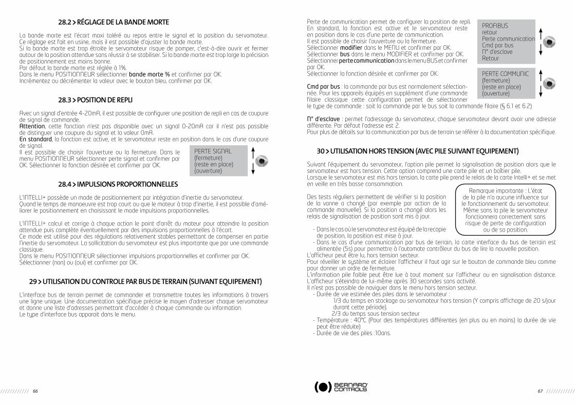
66 67
28.2 RéGLAGE DE LA bANDE MORTE
La bande morte est l’écart maxi toléré au repos entre le signal et la position du servomoteur. Ce réglage est fait en usine, mais il est possible d’ajuster la bande morte.Si la bande morte est trop étroite le servomoteur risque de pomper, c’est-à-dire ouvrir et fermer autour de la position attendue sans réussir à se stabiliser. Si la bande morte est trop large la précision de positionnement est moins bonne.Par défaut la bande morte est réglée à 1%.Dans le menu POSITIONNEUR sélectionner bande morte % et confirmer par OK.Incrémentez ou décrémenter la valeur avec le bouton bleu, confirmer par OK.
28.3 POSITION DE REPLI
Avec un signal d’entrée 4-20mA, il est possible de configurer une position de repli en cas de coupure de signal de commande.Attention, cette fonction n’est pas disponible avec un signal 0-20mA car il n’est pas possible de distinguer une coupure du signal et la valeur 0mA.En standard, la fonction est active, et le servomoteur reste en position dans le cas d’une coupure de signal.Il est possible de choisir l’ouverture ou la fermeture. Dans le menu POSITIONNEUR sélectionner perte signal et confirmer par OK. Sélectionner la fonction désirée et confirmer par OK.
28.4 IMPULSIONS PROPORTIONNELLES
L’INTELLI+ possède un mode de positionnement par intégration d’inertie du servomoteur.Quand le temps de manoeuvre est trop court ou que le moteur à trop d’inertie, il est possible d’amé-liorer le positionnement en choisissant le mode impulsions proportionnelles.
L’INTELLI+ calcul et corrige à chaque action le point d’arrêt du moteur pour atteindre la position attendue puis complète éventuellement par des impulsions proportionnelles à l’écart.Ce mode est utilisé pour des régulations relativement stables permettant de compenser en partie l’inertie du servomoteur. La sollicitation du servomoteur est plus importante que par une commande classique.Dans le menu POSITIONNEUR sélectionner impulsions proportionnelles et confirmer par OK. Sélectionner (non) ou (oui) et confirmer par OK.
29 UTILISATION DU CONTROLE PAR bUS DE TERRAIN (SUIVANT EQUIPEMENT)
L’interface bus de terrain permet de commander et transmettre toutes les informations à travers une ligne unique. Une documentation spécifique précise le moyen d’adresser chaque servomoteur et donne une liste d’adresses permettant d’accéder à chaque commande ou information.Le type d’interface bus apparait dans le menu.
PERTE SIGNAL(fermeture)(reste en place)(ouverture)
Perte de communication permet de configurer la position de repli.En standard, la fonction est active et le servomoteur reste en position dans le cas d’une perte de communication.Il est possible de choisir l’ouverture ou la fermeture.Sélectionner modifierdansleMENUetconfirmerparOK.Sélectionner busdanslemenuMODIFIERetconfirmerparOK.Sélectionner perte communication dans le menu BUS et confirmer par OK.Sélectionner la fonction désirée et confirmer par OK.
Cmd par bus : la commande par bus est normalement sélection-née. Pour les appareils équipés en supplément d’une commande filaire classique cette configuration permet de sélectionner le type de commande : soit la commande par le bus soit la commande filaire (§ 6.1 et 6.2)
N° d’esclave : permet l’adressage du servomoteur, chaque servomoteur devant avoir une adresse différente. Par défaut l’adresse est 2.Pour plus de détails sur la communication par bus de terrain se référer à la documentation spécifique.
30 UTILISATION hORS TENSION (AVEC PILE SUIVANT EQUIPEMENT)
Suivant l’équipement du servomoteur, l’option pile permet la signalisation de position alors que le servomoteur est hors tension. Cette option comprend une carte pile et un boîtier pile.Lorsque le servomoteur est mis hors tension, la carte pile prend le relais de la carte Intelli+ et se met en veille en très basse consommation.
Des tests réguliers permettent de vérifier si la position de la vanne a changé (par exemple par action de la commande manuelle). Si la position a changé alors les relais de signalisation de position sont mis à jour.
- Dans le cas où le servomoteur est équipé de la recopie de position, la position est mise à jour.
- Dans le cas d’une communication par bus de terrain, la carte interface du bus de terrain est alimentée (5s) pour permettre à l’automate contrôleur du bus de lire la nouvelle position.
L’afficheur peut être lu, hors tension secteur.Pour réveiller le système et éclairer l’afficheur il faut agir sur le bouton de commande bleu comme pour donner un ordre de fermeture.L’information pile faible peut être lue à tout moment sur l’afficheur ou en signalisation distance. L’afficheur s’éteindra de lui-même après 30 secondes sans activité.Il n’est pas possible de naviguer dans le menu hors tension secteur.
- Durée de vie estimée des piles dans le servomoteur : 1/3 du temps en stockage ou servomoteur hors tension (Y compris affichage de 20 s/jour
durant cette période). 2/3 du temps sous tension secteur- Température : 40°C (Pour des températures différentes (en plus ou en moins) la durée de vie
peut être réduite)- Durée de vie des piles :10ans.
PROFIBUSretourPerte communicationCmd par busN° d’esclaveRetour
PERTECOMMUNIC(fermeture)(reste en place)(ouverture)
Remarque importante : L’état de la pile n’a aucune influence sur le fonctionnement du servomoteur. Mêmesanslapileleservomoteurfonctionnera correctement sans risque de perte de configuration
ou de sa position.

68 69
31 COMMENT ChANGER L’ORIENTATION DE L’AFFIChEUR
Dans le cas d’une version étanche, il est possible d’orienter l’afficheur et les boutons de commande tous les 90°. Déposer le capot de l’afficheur (4 vis) et orienter la carte dans la position voulue.Reposer le capot en l’orientant pour placer les boutons sous l’afficheur.
32 PROTECTION FUSIbLES
L’alimentation de l’INTELLI+ comprend un transformateur et des fusibles.Primaire : fusible 6,3 x 32mm - 0,5A - rapide (situé sur le transformateur).Secondaire : circuits internes, protection par fusible automatique (sans intervention)Alimentationauxiliaire24Vdisponibleaubornier,protectionparfusibleautomatique(sansintervention).
33 UTILISATION AVEC bOITIER FPI SEPARE (OPTION)
L’INTELLI+ peut être fourni en boitier séparé pour être éloigné du servomoteur jusqu’à 50 mètres. BERNARD CONTROLS fournit des boitiers étanches similaires au boitier monté sur le servomoteur mais avec 2 boites de raccordement étanches. Une boite de raccordement est utilisée par le client, l’autre boite est utilisée pour le raccordement au servomoteur. Entre le servomoteur et le coffret, prévoir un câblepuissanceetuncâblecontrôle.Lecâblecontrôleseraprotégéélectriquementparunblindage.Vérifierlecâblageavantmisesoustension.Lamiseenserviceestidentiqueàcelledel’INTELLI+intégré.
34 ENTRETIEN
Les servomoteurs sont graissés à vie et ne requièrent en conséquence aucun entretien particulier. Il convient toutefois de vérifier périodiquement l’état de la tige de vanne et son écrou, ceux-ci devant être propres et bien lubrifiés.Si les motorisations sont rarement sollicitées il est recommandé d’établir un programme périodique de manoeuvres d’entretien.
Dans le cas d’un servomoteur équipé de l’option pileQuand l’autonomiede la pile est trop faibleun indicateur«pile faible»apparait sur l’afficheur ou est transmis à distance, suivant la configuration de l’appareil.Il est impératif de remplacer les piles par ce modèle : 2pilesOMNICELModèleER14505HDLithiumThionylChloride(Li-SOCl2)Autrespossibilités:MICROBATER14505MetEVEER14505M
Sur lesversionétanchesSTetSQ,unmodèleéquivalent restepossible (TailleAA,2.2Ah,3.6V,400mA,-40°/+85°C).
PRO
BLE
ME
CAU
SER
EMED
YE
L'af
fiche
ur e
st é
tein
tA
limen
tatio
n du
serv
omot
eur
Vérifi
erla
tens
ion
d’alim
enta
tion
(bor
nesL1
,L2,L3
entrip
hasé
).La
te
nsio
n es
t in
diqu
ée s
ur la
pla
que
sign
alét
ique
.
Fusi
ble
coup
éVé
rifier
l’ét
atd
ufu
sible
etle
remplac
ersin
éces
saire
(le
fusible
estac
colé
au t
rans
form
ateu
r).
Auc
un fo
nctio
nnem
ent
L’af
fiche
ur e
st e
n m
ode
men
uMet
tre
lesélec
teur
loca
l/d
ista
nce
suro
ffp
uissu
rloc
alp
ourp
asse
ren
mod
e co
mm
ande
(affi
chag
e : %
pos
ition
)
Une
liai
son
infr
arou
ge e
st é
tabl
ieSi
une
liai
son
infr
arou
ge e
st é
tabl
ie (s
igle
IR s
ur l’
affic
heur
en
haut
à
droi
te) i
l n’e
st p
as p
ossi
ble
de fa
ire u
ne c
omm
ande
par
les
bout
ons.
Re
tirer
la li
aiso
n in
frar
ouge
.
Déc
lenc
hem
ent
prot
ectio
n
ther
miq
ue m
oteu
rU
n ca
rré n
oir a
ppar
aît
sur l
’affi
cheu
r en
bas
au m
ilieu
pou
r sig
nale
r la
prés
ence
d’u
ne a
larm
e.
Alle
r dan
s m
enu
/ con
sulte
r / a
larm
es p
our v
érifi
er la
pré
senc
e d’
une
alar
me
ther
miq
ue m
oteu
r. Le
ser
vom
oteu
r ser
a de
nou
veau
dis
poni
ble
aprè
s re
froi
diss
emen
t du
mot
eur.
Auc
un fo
nctio
nnem
ent
et le
sy
mbo
le d
’une
clé
ou
le s
igle
ESD
es
t af
fiché
Un
ordr
e d’
inte
rdic
tion
de
com
man
de lo
cale
ou
d’un
e co
mm
ande
d’u
rgen
ce e
st p
rése
nt
Vérifi
erd
anslem
enu
comman
des/c
omman
dea
ux.1
ou2
siu
nein
ter-
dict
ion
(ou
com
man
de d
’urg
ence
) n’e
st p
as c
onfig
urée
ain
si q
ue l’
état
du
cont
act
(ouv
ert
ou fe
rmé)
pou
r eff
ectu
er c
ette
com
man
de à
dis
tanc
e.
Vérifi
ere
nsuite
que
lera
ccor
demen
tef
fect
uésur
leb
ornier
clie
ntn
eco
r-re
spon
d pa
s à
une
inte
rdic
tion
de c
omm
ande
(ou
com
man
de d
’urg
ence
). Ex
: si l
a co
nfigu
ratio
n es
t su
r com
man
de a
ux.1,
inte
rd c
de lo
c et
con
tact
(o
)= in
ter i
l est
alo
rs n
éces
saire
d’é
tabl
ir un
con
tact
à d
ista
nce
sur l
a bo
rne
11 p
our s
uppr
imer
l’in
terd
ictio
n.
Le s
ervo
mot
eur f
onct
ione
en
loca
l m
ais
pas
en d
ista
nce
Séle
cteu
r loc
al /
dist
ance
sur
loca
l ou
off
(arrê
t)Ba
scul
er le
sél
ecte
ur lo
cal /
dis
tanc
e su
r la
posi
tion
dist
ance
Com
man
de p
ar c
onta
ct :
pas
de
tens
ion
entre
lesbo
rnes
6e
t7
Vérifi
erq
u’ilex
iste
un
shun
tau
bor
nier
clie
nte
ntre
lesbo
rnes
5e
t6.
Vérifi
erla
pré
senc
ed’un
ealar
me
«24V
aux
iliaire
»
Com
man
de p
ar te
nsio
n : t
ensi
on
non
adpa
tée
à l’e
ntré
eVé
rifier
lera
ccor
demen
ten
com
man
dep
arte
nsion:
Tens
ion
de10
à55
Volt:
born
e5
Tens
ion
de 5
5 à
250
volt:
bor
ne 4
35 ANOMALIE DE FONCTIONNEMENT
Si le fonctionnement de l’appareil semble douteux, placer en premier lieu le sélecteur local / distance sur la position locale, et agir sur les commandes ouverture et fermeture..

70 71
PRO
BLE
ME
CAU
SER
EMED
E
Le s
erm
oteu
r fon
ctio
nne
en d
ista
nce
mai
s pa
s en
loca
lSé
lect
eur l
ocal
/dis
tanc
e su
r dis
tanc
e ou
off
(arrê
t)Ba
scul
er le
sél
ecte
ur lo
cal /
dis
tanc
e su
r la
posi
tion
loca
le
Un
ordr
e d’
inte
rdic
tion
de c
omm
ande
lo
cale
est
pré
sent
(le
sym
bole
d’u
ne
clé
est
affic
hé) o
u la
sél
ectio
n lo
cal/
dist
ance
se
fait
à di
stan
ce
Vérifi
erd
anslem
enu
comman
des/c
omman
dea
ux.1
ou2
siu
nein
terd
ictio
nn’es
tpa
sco
nfigu
rée
ains
i que
l’ét
at d
u co
ntac
t (o
uver
t ou
ferm
é) p
our e
ffec
tuer
cet
te c
omm
ande
à
dist
ance
.Vér
ifier
ens
uite
que
lera
ccor
demen
tef
fect
uésur
leb
ornier
clie
ntn
eco
rresp
ond
pas
à un
e in
terd
ictio
n de
com
man
de.
Ex: s
i la
confi
gura
tion
est
sur c
omm
ande
aux
.1, in
terd
cde
loc
et c
onta
ct (o
)= in
ter
il es
t al
ors
néce
ssai
re d
’éta
blir
un c
onta
ct à
dis
tanc
e su
r la
born
e 11
pou
r sup
prim
er
l’inte
rdic
tion.
Le s
ervo
mot
eur n
e to
urne
pas
dan
s le
bon
sen
s de
rota
tion
Confi
gura
tion
mal
ada
ptée
Vérifi
erdan
slem
enumod
ifier/
posit
ion/s
enspo
urfe
rmet
ure:F
ermet
urese
nshoraireou
antih
orai
re.
Lem
oteu
raé
téd
écâb
lée
tto
urne
en
sen
s in
vers
e (c
hang
emen
t de
m
oteu
r)
Lors
d’u
n ch
ange
men
t de
mot
eur i
l fau
t res
pect
er le
s re
père
s de
s fil
s. En
cas
de
dout
e vé
rifier
la
conf
orm
ité d
u se
ns d
e ro
tatio
n.
L’in
vers
ion
de s
ens
de ro
tatio
n du
mot
eur s
e fa
it en
per
mut
ant l
es fi
ls 2
et 3
du
born
ier m
oteu
r sit
ué d
ans
le b
oîtie
r de
cont
rôle
.
Impo
ssib
le d
e re
ntre
r dan
s le
men
uSé
lect
eur s
ur d
ista
nce
ou o
ff o
u pr
ésen
ce d
’une
inte
rdic
tion
loca
leL’
accè
s au
men
u pa
r les
bou
tons
n’e
st p
ossi
ble
qu’e
n m
ode
loca
l c’e
st à
dire
sél
ecte
ur s
ur
loca
leta
bsen
ced’une
inte
rdictio
nde
com
man
delo
cale.M
ettre
lesélec
teur
su
r loc
al e
t voi
r plu
s ha
ut le
s vé
rifica
tions
à fa
ire s
ur le
s co
mm
ande
s au
x.1
et 2
.
Les
para
mèt
res
dans
le m
enu
ne
peuv
ent
pas
être
mod
ifiés
Une
mod
ifica
tion
dans
le m
enu
ne
peut
pas
êtr
e fa
ite d
ans
le m
enu
cons
ulte
r
Alle
r dan
s le
men
u m
odifi
er. C
erta
in p
aram
ètre
s pe
uven
t un
ique
men
t êt
re c
onsu
ltés.
Les
mod
ifica
tions
faite
s n’
ont
pas
été
pris
es e
n co
mpt
eEn
cou
rs d
e m
odifi
catio
n au
cun
chan
gem
ent
n’es
t ef
fect
ué
réel
lem
ent.
Il fa
ut v
alid
er la
mod
ifi-
catr
ion
pour
êtr
e en
regi
stré
e
Une
fois
les
mod
ifica
tions
faite
s re
mon
ter l
es m
enus
en
séle
ctio
nnan
t re
tour
pui
s O
K ju
squ’
à lir
e : (
mod
if ok
?) c
onfir
mer
par
OK
pour
enr
egis
trer
les
mod
ifica
tions
L’ac
tion
vola
nt n
’a p
as é
té d
étec
tée
L’act
ion
vola
nt e
st d
étec
tée
depu
is
la d
erni
ère
man
oeuv
re é
lect
rique
et
à co
nditi
on q
ue le
ser
vom
oteu
r res
te
norm
alem
ent s
ous
tens
ion.
La d
étec
tion
ne
sig
nale
auc
un d
épla
cem
ent d
épas
-sa
nt 10
% d
e la
cour
se.
Refa
ire la
dét
ectio
n da
ns le
s bo
nnes
con
ditio
ns.
L’al
arm
e ex
cès
de d
émar
rage
ap
para
îtL’
INTE
LLI+
sur
veill
e le
nom
bre
de
dém
arra
ges
effe
ctué
s pe
ndan
t le
s 12
der
nièr
es h
eure
s et
le c
ompa
re à
ce
lui d
e la
cla
sse
de fo
nctio
nnem
ent
du s
ervo
mot
eur
Cett
e al
arm
e ne
lim
ite p
as le
fonc
tionn
emen
t du
serv
omot
eur m
ais
indi
que
un
fonc
tionn
emen
t in
tens
if du
ser
vom
oteu
r. Si
le ry
thm
e de
dém
arra
ges
rede
vien
t co
nfor
me
à la
des
tinat
ion
de l’
appa
reil,
l’ala
rme
disp
araî
tra.
Le s
ervo
mot
eur f
onct
ionn
e de
m
aniè
re c
aden
cée
en c
ours
de
man
oeuv
re
La fo
nctio
n te
mpo
riser
a é
té
confi
guré
eCe
tte
fonc
tion
confi
guré
e da
ns le
men
u te
mpo
riser
per
met
, à la
dem
ande
de
l’util
isat
eur,
d’au
gmen
ter l
e te
mps
de
man
oeuv
re d
u se
rvom
oteu
r.
NOTES

BERNARD CONTROLS4rued’Arsonval-BP70091-95505GonesseCedex-FranceTel:+33.1.34.07.71.00-Fax:+33.1.34.07.71.01E-mail: [email protected]: http://www.bernardcontrols.com
SUBSIDIARIES
BELGIUMBERNARD CONTROLS BENELUXBRUXELLES
[email protected] +32 (0)2 343 41 22
CHINABERNARD CONTROLS CHINAPEKIN
[email protected] +86 (0) 10 6789 2861
GERMANYBERNARD CONTROLS DEUFRATROISDORF
[email protected] +49 22 41 98 340
ITALIABERNARD CONTROLS ITALIAMILAN
[email protected] +39 02 931 85 233
KOREA (REPUBLIC OF)BERNARD CONTROLS KOREASEOUL
[email protected] +82 02-2270-3880
SINGAPOREBERNARD CONTROLS SINGA-PORESINGAPORE
[email protected] +65 65654227
BERNARD CONTROLS SPAINMADRID
[email protected] +34 91 30 41 139
UNITED STATESBERNARD CONTROLS IncHOUSTON
[email protected] +1 281 578 66 66
OFFICES
BANGKOKBERNARD CONTROLSSOUTH-EAST [email protected] +66 2 640 82 64
DUBAÏ BERNARD [email protected] +971 4 344 2010
MOSCOWBERNARD [email protected] +(7 499) 251 06 54 or +(7 916) 911 28 42
AGENTS AND DISTRIBUTORS
AMERICAS
Information on our networkwww. bernardcontrols.com orBack OfficeBERNARD CONTROLS [email protected] +1 281 578 66 66
BRAZILJCNSAO [email protected] +55 11 39 02 26 00
ASIA
Information on our networkwww. bernardcontrols.com
orTo contact our distributorsBack OfficeBERNARD CONTROLS [email protected] +86 10 6789 2861
EUROPE - MIDDLE EAST - AFRICA
Information on our networkwww.bernardcontrols.com orBack Office BERNARD CONTROLS [email protected] +33 (0)1 34 07 71 00
orContact directly agents/distributors
AUSTRIAIPU ING PAUL [email protected] +43 1 602 41 49
CZECH REPUBLICFLUIDTECHNIK BOHEMIA [email protected] +420 548 213 233-5
DENMARKARMATEC A/[email protected] + 45 46 96 00 00
[email protected] +203 582 76 47
FINLANDTALLBERG TECH OY [email protected] +358 0 207 420 740
GREECEPI&MS Entreprises [email protected] +30 210 608 61 52
HUNGARYAPAGYI TRADEIMPEX [email protected] +36 1 223 1958
MOROCCOAQUATEL [email protected] +212 22 66 55 71
POLANDARNAP Sp Z [email protected] +48 33 81 84004
[email protected] +48 22 864 55 43
SOUTH AFRICAA-Q-RATE AUTOMATION [email protected] +27 11 432 58 31
SWITZERLANDMATOKEM [email protected] +41 61 483 15 40
[email protected] +90 216 326 39 39
UNITED KINGDOMZOEDALE [email protected] +44 12 34 83 28 28
Exhaustive list of agents and distributors on www.bernardcontrols.com