Embed Size (px)
Citation preview
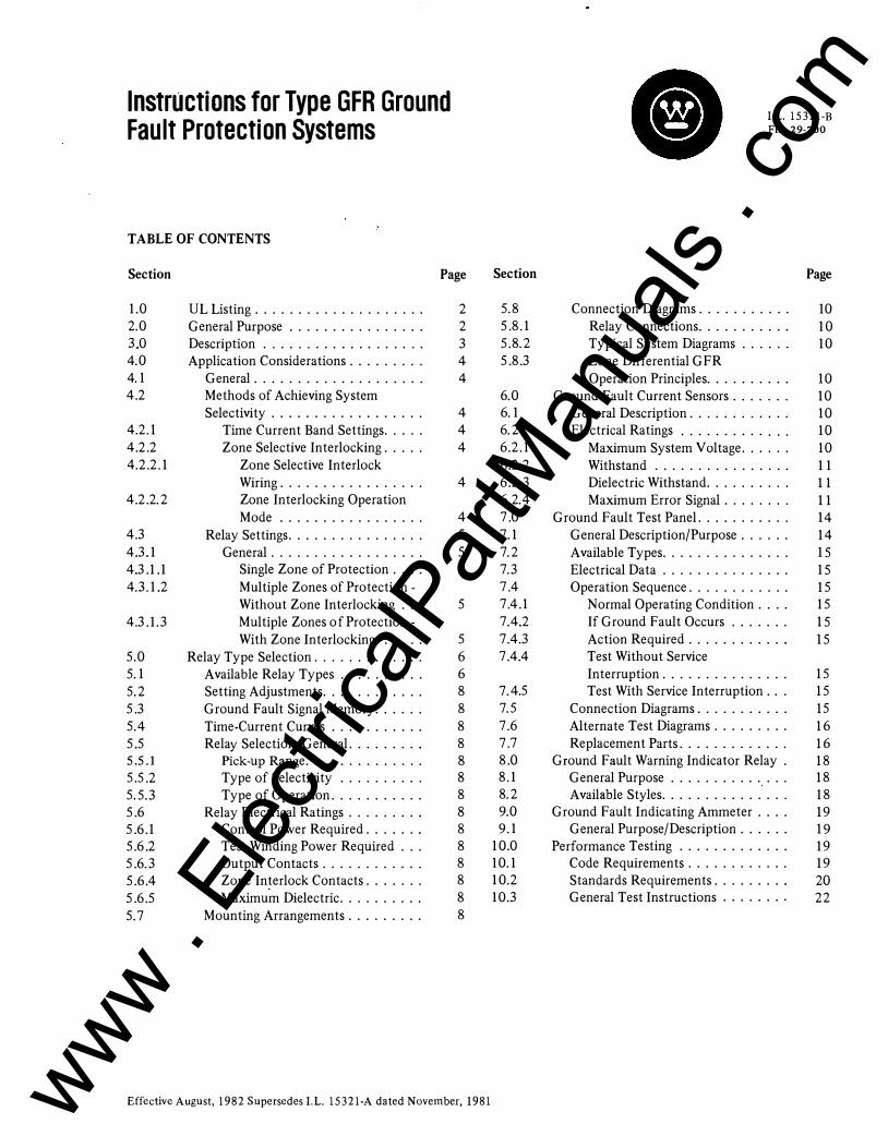
Instructions for Type GFR Ground Fault Protection Systems
TABLE OF CONTENTS
Section Page
1.0 2.0 3.0 4.0 4.1 4.2
4.2.1 4.2.2 4.2.2.1
4.2.2.2
4.3 4.3.1 4.3.1.1 4.3.1.2
4.3.1.3
5.0 5.1 5.2 5.3 5.4 5.5 5.5.1 5.5.2 5.5.3 5.6 5.6.1 5.6.2 5.6.3 5.6.4 5.6.5 5.7
UL Listing ................... . General Purpose ............... . Description . . . . . . . . . . . . . . . . . . . Application Considerations ........ .
General . . . . . . . ............ . Methods of Achieving System Selectivity ................. .
Time Current Band Settings . . . . . Zone Selective Interlocking .... .
Zone Selective Interlock Wiring ................ . Zone Interlocking Operation Mode ................ .
Relay Settings ............... . General ................. .
Single Zone of Protection . . . . Multiple Zones of Protection -Without Zone Interlocking ... Multiple Zones of Protection -With Zone Interlocking . . . . . .
Relay Type Selection ............ . Available Relay Types ......... . Setting Adjustments ........... . Ground Fault Signal Memory ..... . Time-Current Curves .......... . Relay Selection, General. ....... .
Pick-up Range ............. . Type of Selectivity ......... . Type of Operation .......... .
Relay Electrical Ratings ........ . Control Power Required ...... . Test Winding Power Required . . . Output Contacts ........... . Zone Interlock Contacts ...... . Maximum Dielectric ......... .
Mounting Arrangements ........ .
2 2 3 4 4
4 4 4
4
4 5 5 5
5
5 6 6 8 8 8 8 8 8 8 8 8 8 8 8 8 8
Effective August, 1982 Supersedes I.L. 15321-A dated November, 1981
Section
5.8 5.8.1 5.8.2 5.8.3
6.0 6.1 6.2 6.2.1 6.2.2 6.2.3 6.2.4 7.0 7.1 7.2 7.3 7.4 7.4.1 7.4.2 7.4.3 7.4.4
7.4.5 7.5 7.6 7.7 8.0 8.1 8.2 9.0 9.1
10.0 10.1 10.2 10.3
I.L. 15321-B File 29-700
Connection Diagrams .......... . Relay Connections .......... . Typical System Diagrams ..... . Zone Differential GFR Operation Principles ......... .
Ground Fault Current Sensors ...... . General Description . . . . . . . . ... . Electrical Ratings ........... . .
Maximum System Voltage ..... . Withstand ............... . Dielectric Withstand ......... . Maximum Error Signal ....... .
Ground Fault Test Panel. ......... . General Description/Purpose . . . . . . Available Types .............. . Electrical Data .............. . Operation Sequence ........... .
Normal Operating Condition . . . . If Ground Fault Occurs ...... . Action Required ........... . Test Without Service Interruption .............. . Test With Service Interruption .. .
Connection Diagrams .......... . Alternate Test Diagrams ........ . Replacement Parts ............ .
Ground Fault Warning Indicator Relay . General Purpose .............. . Available Styles .............. .
Ground Fault Indicating Ammeter ... . General Purpose/Description . . . . . .
Performance Testing ............ . Code Requirements ........... . Standards Requirements ........ . General Test Instructions ....... .
Page
10 10 10
10 10 10 10 10 11 11 11 14 14 15 15 15 15 15 15
15 15 15 16 16 18 18 18 19 19 19 19 20 22
www . El
ectric
alPar
tMan
uals
. com
2
......__..,... __ Adjusting Switches
Turn Screw to lock Settings
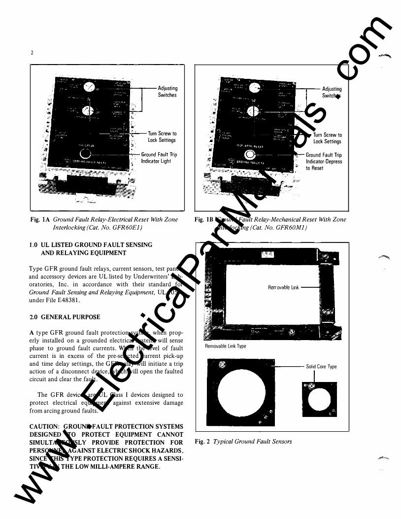
Fig. lA Ground Fault Relay-Electrical Reset With Zone
Interlocking (Cat. No. GFR60El)
1.0 UL LISTED GROUND FAULT SENSING AND RELAYING EQUIPMENT
Type GFR ground fault relays, current sensors, test panels and accessory devices are UL listed by Underwriters' Laboratories, Inc. in accordance with their standard for Ground Fault Sensing and Relaying Equipment, UL 1053, under File £48381.
2.0 GENERAL PURPOSE
A type GFR ground fault protection system, when properly installed on a grounded electrical system, will sense phase to ground fault currents. When the level of fault current is in excess of the pre-selected current pick-up and time delay settings, the GFR relay will initiate a trip action of a disconnect device, which will open the faulted circuit and clear the fault.
The GFR devices are UL Class I devices designed to protect electrical equipment against extensive damage from arcing ground faults.
CAUTION: GROUND FAULT PROTECTION SYSTEMS DESIGNED TO PROTECT EQUIPMENT CANNOT SIMULTANEOUSLY PROVIDE PROTECTION FOR PERSONNEL AGAINST ELECTRIC SHOCK HAZARDS, SINCE THIS TYPE PROTECTION REQUIRES A SENSITIVITY IN THE LOW MILLI-AMPERE RANGE.
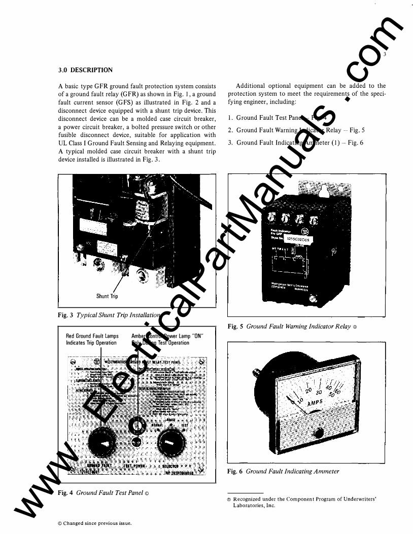
,_........,......_ Adjusting Switches
Turn Screw to lock Settings
Ground Fault Trip Indicator-Depress to Reset
Fig. lB Ground Fault Relay-Mechanical Reset With Zone
Interlocking (Cat. No. GFR60Ml)
Removable Link Type
---- Solid Core Type
Fig. 2 Typical Ground Fault Sensors
www . El
ectric
alPar
tMan
uals
. com
3.0 DESCRIPTION
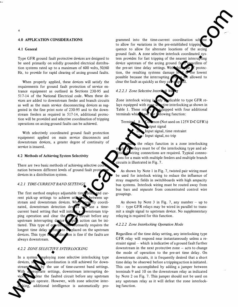
A basic type GFR ground fault protection system consists of a ground fault relay (GFR) as shown in Fig. 1, a ground fault current sensor (GFS) as illustrated in Fig. 2 and a disconnect device equipped with a shunt trip device. This disconnect device can be a molded case circuit breaker, a power circuit breaker, a bolted pressure switch or other fusible disconnect device, suitable for application with UL Class I Ground Fault Sensing and Relaying equipment. A typical molded case circuit breaker with a shunt trip device installed is illustrated in Fig. 3 .
Shunt Trip
Fig. 3 Typical Shunt Trip Installation
Red Ground Fault lamps Indicates Trip Operation
Amber Control Power lamp "ON" Only During Test Operation
Fig. 4 Ground Fault Test Panel ©
© Changed since previous issue.
3
Additional optional equipment can be added to the protection system to meet the requirements of the specifying engineer, including:
1. Ground Fault Test Panel � Fig. 4
2. Ground Fault Warning Indicator Relay� Fig. 5
3. Ground Fault Indicating Ammeter (1) � Fig. 6
Fig. 5 Ground Fault Warning Indicator Relay <D
Fig. 6 Ground Fault Indicating Ammeter
<!l Recognized under the Component Program of Underwriters'
Laboratories, Inc. www . El
ectric
alPar
tMan
uals
. com
4
4.0 APPLICATION CONSIDERATIONS
4.1 General
Type GFR ground fault protective devices are designed to be used primarily on solidly grounded electrical distribution systems rated up to a maximum of 600 volts, 50/60
Hz, to provide for rapid clearing of arcing ground faults.
When properly applied, these devices will satisfy the requirements for ground fault protection of service entrance equipment as outlined in Sections 2 3 0-95 and 517-14 of the National Electrical code. When these devices are added to downstream feeder and branch circuits as well as the main service disconnecting devices as suggested in the fine print note of 2 3 0-95 and to the downstream feeders as required in 517-14, additional protection will be provided and selective coordination of tripping operations on arcing ground faults can be achieved.
With selectively coordinated ground fault protection equipment applied on main service disconnects and downstream devices, a greater degree of continuity of service is insured.
4.2 Methods of Achieving System Selectivity
There are two basic methods of achieving selective coordination between different levels of ground fault protective devices in a distribution system.
4.2.I TIME-CURRENT BAND SETTINGS
The first method employs adjustable time delay and current pick-up settings to achieve selectivity between upstream and downstream devices. When properly coordinated, downstream detection devices will use a timecurrent band setting that will initiate a downstream tripping operation and clear the faulted circuit before any upstream interrupting device tripping action can be initiated. This type of coordination necessarily requires the longest time delay settings to be placed on the upstream devices. This type of coordination is fine if the faults are always downstream.
4.2.2 ZONE SELECTIVE INTERLOCKING
In a system employing zone selective interlocking type devices, selective coordination is still achieved for downstream faults by the use of time-current band settings. With appropriate settings, downstream interrupting devices will clear the faulted circuit before any upstream device can operate. However, with zone selective interlocking, additional intelligence is automatically pro-
grammed into the time-current coordination scheme to allow for variations in the pre-established tripping sequence to allow for alternate locations of the arcing ground fault. A zone selective interlock coordinated system provides for fast tripping of the nearest interrupting device upstream of the arcing ground fault regardless of the pre-set time delay settings. With this type of protection, the resulting systems damage level is the lowest possible because the interrupting devices are allowed to clear the fault as quickly as they can respond.
4.2.2.I Zone Selective Interlock Wiring
Zone interlock wiring is only applicable to type GFR relays equipped with zone selective interlocking as shown in Table I. These relays are equipped with four additional terminals which have the following function:
Terminal 8 - Common (Not used on 1 25V D-C GFR's) 9 - Output signal
10 - Input signal, time restraint 11 - Input signal, no trip
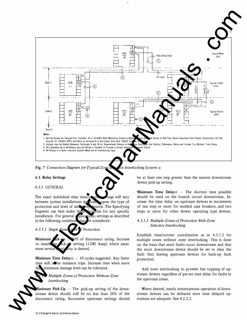
To make the relays function in a zone interlocking mode, all relays must be of the interlocking type and additional wiring connections are required. Typical connections for a main with multiple feeders and multiple branch circuits is illustrated in Fig. 7.
As shown by Note I in Fig. 7, twisted pair wiring must be used for interlock wiring to reduce the influence of stray magnetic fields in switchboards with high ampacity bus systems. Interlock wiring must be routed away from bus bars and separate from concentrated control wire groupings.
As shown by Note 3 in Fig. 7, any number - up to 50 - type GFR relays may be wired in parallel to transmit a single signal to upstream device. No supplementary relaying is required for this function.
4.2.2.2 Zone Interlocking Operation Mode
Regardless of the time delay setting, any interlocking type GFR relay will respond near instantaneously unless a restraint signal - which is indicative of a ground fault further downstream in the next protective zone - acts to change the mode of operation to the pre-set time delay. On downstream circuits, it is frequently desired that a short time delay be observed before a tripping action is initiated. This can be accomplished by adding a jumper between terminals 9 and 10 on the downstream relay as indicated by Note 2 on Fig. 7. This jumper should not be used on any upstream relay as it will defeat the zone interlocking function. www .
Elec
tricalP
artM
anua
ls . c
om
Trme Delay Input
Zone 1
Zone 3 Notes:
TypiCal Marn
GFR
TypiCal Feeder GFR's
TypiCal Branch GFR's
5
1. Wiring Should be Twisted Parr, Number 14 or 16 AWG With Maxrmum Distance Between Frrst and Last Zones of 250 Feet Route Separate from Power Conductors. Do Not
Ground. On 125VDC GFR's the Wire to Terminal 8 is Not Used. Only One 125VDC Source rs Allowed.
2. Jumper may be Added Between Terminals 9 and 10 on Downstream Relays to Add Trme Delay per Dial Setting. Otherwise, Relay wrll lnrtrate Tnp Wrthout Trme Delay.
3. Any Quantity-Up to 50-Relays may be Wired in Parallel to Provide a Srngle Upstream Restrarnt Srgnal.
4. All Relays in a Zone Interlock System Must be of Interlocking Type.
Fig. 7 Connection Diagram for Typical Zone Selective Interlocking System ©
4.3 Relay Settings
4.3.1 GENERAL
The exact individual relay time/current settings will vary between system installations depending upon the type of protection and level of selectivity desired. The Specifying Engineer can best make these decisions for any specific installation. For general applications, settings as described in the following conditions may be considered.
4.3.1.1 Single Zone Level of Protection
Minimum Pick-up - 20% of disconnect rating. Increase to maximum pick-up setting (1200 Amp) where maximum service continuity is desired.
Minimum Time Delay© - 10 cycles suggested. Any faster time will invite nuisance trips. Increase time when more than minimum damage level can be tolerated.
4.3.1.2 Multiple Zones of Protection Without Zone
Interlocking
Minimum Pick-Up - The pick-up setting of the downstream device should still be no less than 20% of the disconnect rating. Successive upstream settings should
© Changed since previous issue.
be at least one step greater than the nearest downstream device pick-up setting.
Minimum Time Delay© - The shortest time possible should be used on the branch circuit downstream. Increase the time delay on upstream devices in increments of one step or more for molded case breakers, and two steps or more for other slower operating type devices.
4.3.1.3 Multiple Zones of Protection With Zone
Selective Interlocking
Establish time/current coordination as in 4. 3.1.2 for multiple zones without zone interlocking. This is done on the basis that most faults occur downstream and that the most downstream device should be set to clear the fault first leaving upstream devices for back-up fault protection.
Add zone interlocking to provide fast tripping of upstream devices regardless of pre-set time delay for faults in the upstream zones.
Where desired, nearly instantaneous operation of downstream devices can be defeated were time delayed operations are adequate. See 4.2.2.2. www .
Elec
tricalP
artM
anua
ls . c
om
6
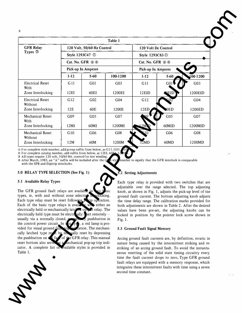
Table 1
GFR Relay 120 Volt, 50/60 H z Control 120 Volt De Control Types t!>
Style 1293C4 7 (!) Style 1293C83 <D Cat. No. GFR ® ® Cat. No. GFR ® ®
Pick-up In Amperes Pick-up In Amperes
1-12 5-60 100-1200 1-12 5-60 100-1200
Electrical Reset Gil G Ol G0 3 Gil G Ol G0 3 With Zone Interlocking 12EI 60EI 1200EI 12EID 60EID 1200EID
Electrical Reset G12 G02 G04 G12 G02 G04 Without Zone Interlocking 12E 60E 1200E 12ED 60ED 1200ED
Mechanical Reset G0 9 GOS G07 G0 9 G OS G07 With Zone Interlocking 12MI 60MI 1200MI 12MID 60MID 1200MID
Mechanical Reset Gl O G06 G08 G l O G06 G08 Without Zone Interlocking 12M 60M !200M 12MD 60MD 1200MD
(l) For complete style number, add group suffix from below, as Gll, G01, G03. @ For complete catalog number, add suffix from below, as 12EI, 60EI, 1200EI. l2l All types require 120 volt, 50/60Hz. control for test winding. ® After March, 1983, an "A" suffix will be included after the GFR style number to signify that the GFR interlock is comparable
with the SPB and Digitrip interlocks.
5.0 RELAY TYPE SELECTION (See Fig. 1)
5.1 Available Relay Types
The GFR ground fault relays are available in two basic types, ie, with and without zone selective interlocking. Each type relay must be reset following a trip operation. Each of the basic type relays is available with either an electrically held or mechanically latched output relay. The electrically held type must be electrically reset remotely -usually via a normally closed, momentary pushbutton in the control power circuit. In this type, a red lamp is provided for visual ground fault trip indication. The mechanically latched type must be manually reset by depressing the pushbutton on the face of the GFR relay. This manual reset bottom also serves as a mechanical pop-up trip indicator. A complete list of available styles is provided in Table 1.
5.2 Setting Adjustments
Each type relay is provided with two switches that are adjustable over the range selected. The top adjusting knob, as shown in Fig. 1, adjusts the pick-up level of the ground fault current. The bottom adjusting knob adjusts the time delay range. The calibration marks provided for both adjustments are shown in Table 2. After the desired values have been pre-set, the adjusting knobs can be locked in position by the pointer lock screw shown in Fig. 1.
5.3 Ground Fault Signal Memory
Arcing ground fault currents are, by definition, erratic in nature being caused by the intermittent striking and restriking of an arcing ground fault. To avoid the instantaneous resetting of the solid state timing circuitry every time the fault current drops to zero, Type GFR ground fault relays are equipped with a memory response, which integrates these intermittent faults with time using a seven second time constant.
www . El
ectric
alPar
tMan
uals
. com

7
MINIMUM PICK· UP SETIINGS. AMPERES
Fig. 8 GFR Relay Time-Current Curve ©
© Changed since previous issue. www . El
ectric
alPar
tMan
uals
. com
8
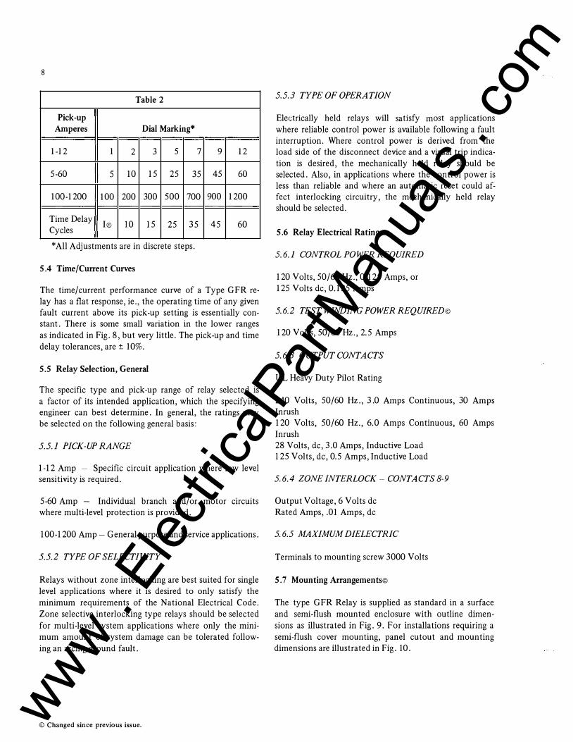
Table 2
Pick-up Amperes Dial Marking*
1-12 1 2 3 5 7 9 12
5-60 5 10 15 25 35 45 60
100-1200 100 200 300 500 700 900 1200
Time Delay I© 10 15 25 35 45 60
Cycles
*All Adjustments are in discrete steps.
5.4 Time/Current Curves
The time/current performance curve of a Type GFR relay has a flat response, ie., the operating time of any given fault current above its pick-up setting is essentially constant. There is some small variation in the lower ranges as indicated in Fig. 8, but very little. The pick-up and time delay tolerances, are ± 10%.
5.5 Relay Selection, General
The specific type and pick-up range of relay selected is a factor of its intended application, which the specifying engineer can best determine. In general, the ratings may be selected on the following general basis:
5.5.1 PICK-UP RANGE
1-12 Amp - Specific circuit application where low level sensitivity is required.
5-60 Amp - Individual branch and/or motor circuits where multi-level protection is provided.
100-1200 Amp- General purpose and service applications.
5.5.2 TYPE OF SELECTIVITY
Relays without zone interlocking are best suited for single level applications where it is desired to only satisfy the minimum requirements of the National Electrical Code. Zone selective interlocking type relays should be selected for multi-level system applications where only the minimum amount of system damage can be tolerated following an arcing ground fault.
© Changed since previous issue.
5.5.3 TYPE OF OPERATION
Eledrically held relays will satisfy most applications where reliable control power is available following a fault interruption. Where control power is derived from the load side of the disconnect device and a visual trip indication is desired, the mechanically held relay should be selected. Also, in applications where the control power is less than reliable and where an automatic reset could affect interlocking circuitry, the mechanically held relay should be selected.
5.6 Relay Electrical Ratings
5.6.1 CONTROL PO WER REQUIRED
120 Volts, 50/60Hz., 0.125 Amps, or 125 Volts de, 0.125 Amps
5.6.2 TEST WINDING POWER REQUIRED©
120 Volts, 50/60Hz., 2.5 Amps
5.6.3 OUTPUT CONTACTS
UL Heavy Duty Pilot Rating
240 Volts, 50/60 Hz., 3.0 Amps Continuous, 30 Amps Inrush 120 Volts, 50/60 Hz., 6.0 Amps Continuous, 60 Amps Inrush 28 Volts, de, 3.0 Amps, Inductive Load 125 Volts, de, 0.5 Amps, Inductive Load
5.6.4 ZONE INTERLOCK- CONTACTS 8-9
Output Voltage, 6 Volts de Rated Amps, .01 Amps, de
5. 6.5 MAXIMUM DIELECTRIC
Terminals to mounting screw 3000 Volts
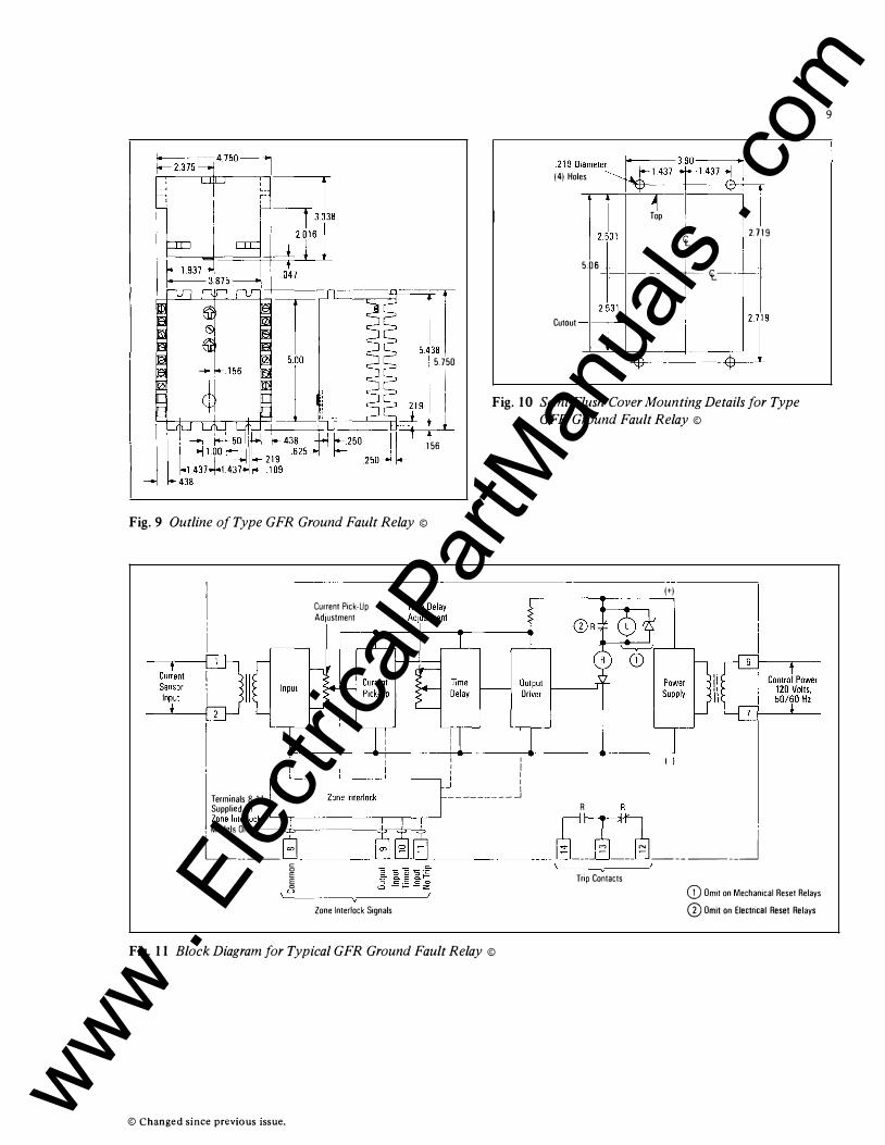
5. 7 Mounting Arrangements©
The type GFR Relay is supplied as standard in a surface and semi-flush mounted enclosure with outline dimensions as illustrated in Fig. 9. For installations requiring a semi-flush cover mounting, panel cutout and mounting dimensions are illustrated in Fig. 10.
www . El
ectric
alPar
tMan
uals
. com
"'] 5.750
m m•m•"�m ''"� 141 Holes 1437 _.j+-- 1437
- -r- -
Tl �
Top , � 2.719
5.06 -t-ct._-- I-
Cutout 2 �3�
I iT -$--I I Fig. 10 Semi-Flush Cover Mounting Details for Type
GFR Ground Fault Relay ©
.156
Fig. 9 Outline of Type GFR Ground Fault Relay ©
Current Pick-Up Adjustment
I I I I I I
1+1
��rp�:re
a�s0�-11 Ll_,--__ z_
o
_
ne_l_nt
-
er
-
lo-ck --,-,----,---'��------- -J R
Zone Interlock 1 1 1 1 � D , c�-n-
ly
�----8-�_§ __ ____ @] ____ � --- � ______ j c
E §
'-'
Zone Interlock Signals
Fig. 11 Block Diagram for Typical GFR Ground Fault Relay ©
© Changed since previous issue.
Trip Contacts (i) Omit on Mechanical Reset Relays CD Omit on Electrical Reset Relays
9
www . El
ectric
alPar
tMan
uals
. com
10
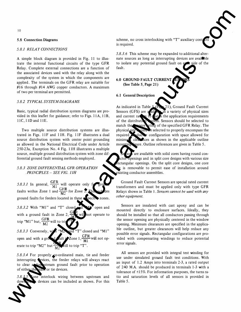
5.8 Connection Diagrams
5. 8.1 RELAY CONNECTIONS
A simple block diagram is provided in Fig. 11 to illustrate the internal functional circuits of the type GFR Relay. Complete external connections are a function of the associated devices used with the relay along with the complexity of the system in which the components are applied. The terminals on the GFR relay are suitable for #16 through #14 AWG copper conductors. A maximum of two per terminal are permitted.
5.8.2 TYPICAL SYSTEM DIAGRAMS
Basic, typical radial distribution system diagrams are provided in this leaflet for guidance; refer to Figs. llA, l iB, ll C, l iD and liE.
Two multiple source distribution systems are illustrated in Figs. 11F and l lH. Fig. l l F illustrates a dual source distribution system with center point grounding as allowed in the National Electrical Code under Article 250-23a, Exception No. 4 Fig. 11 H illustrates a multiple source, multiple ground distribution system with zone differential ground fault sensing methods employed.
5.8.3 ZONE DIFFERENTIAL GFR OPERATION
.PRINCIPLES- SEE FIG. llH
5.8.3.1 In general, G:� will operate only for ground
faults within Zone 1 and �� for Zone 2. This includes
ground faults for feeders located in these respective zones.
5.8.3.2 With " M l " and "T" closed and "M2" open and
with a ground fault in Zone 2, G:� will not operate to
trip "M 1" but, �2R
will to trip "T".
5.8.3.3 Conversely, with "M2" and "T" closed and " M1"
open and with a ground fault in Zone 1, ��will not op
erate to trip "M2" but G�� will to trip "T".
5.8.3.4 For properly co-ordinated main, tie and feeder interrupting devices, the feeder relays will always react to clear a downstream ground fault prior to operation of either the main or tie devices.
5.8.3.5 Zone interlock wiring between upstream and downstream devices can be included as shown. For this
scheme, no cross interlocking with "T" auxiliary contacts is required.
5.8.3.6 This scheme may be expanded to additional alternate sources as long as interrupting devices are available to isolate any potential ground fault on each side of the fault.
6.0 GROUND FAULT CURRENT SENSORS (See Table 5, Page 21)
6.1 General Description
As indicated in Table 5 (Page 21), Ground Fault Current Sensors (GFS) are available in a variety of physical sizes and current ratings to match the application requirements of the distribution system. Sensors should be selected to match the ampere rating of the specified GFR Relay. The physical size should be selected to properly encompass the required conductor configuration with space allowed for minimum clearances as shown in the applicable outline mounting figure. Outline references are given in Table 5.
Sensors are available with solid cores having round conductor openings and in split core designs with various size rectangular openings. On the split core designs, one core leg is removable to permit ease of installation around existing conductor assemblies.
Ground Fault Current Sensors are special rated current transformers and must be applied only with type GFR Relays shown in Table 1 . Sensors cannot be used with any
other equipment.
Sensors are insulated with cast apoxy and can be mounted directly to enclosure surfaces. Ideally, they should be installed so that all conductors passing through the sensor opening are physically centered in the window opening. Minimum clearances are specified in the applicable outline, but greater clearances will help reduce any possible error signals. Rectangular configurations are provided with compensating windings to reduce potential error signals.
All sensors are provided with integral test winding for use under simulated ground fault test conditions. With an input of 1.2 Amps into terminals 2-3, a rated output of 240 M.A. should be produced in terminals 1-3 with a tolerance of ±15%. For information purposes, the turns ratio and saturation levels of all sensors is provided in Table 5.
www . El
ectric
alPar
tMan
uals
. com
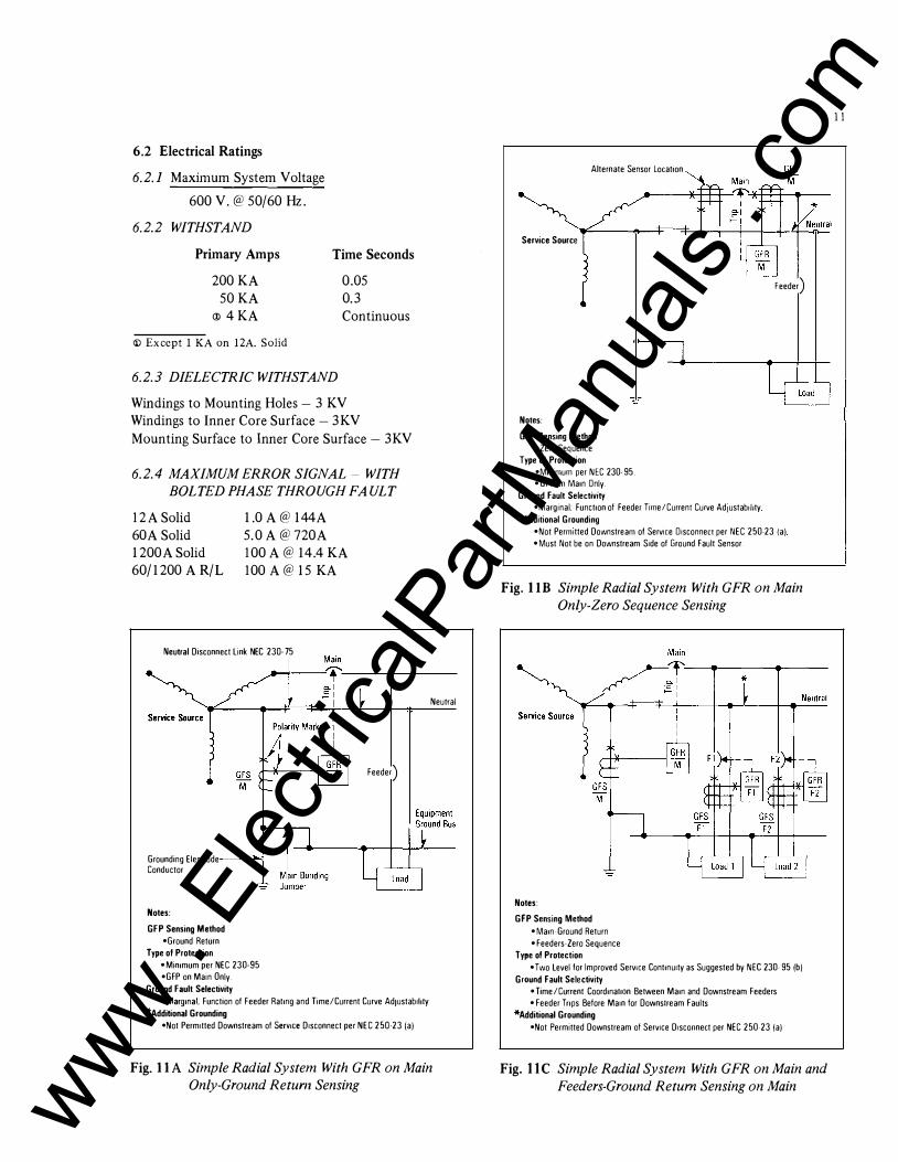
6.2 Electrical Ratings
6.2.1 Maximum System Voltage
600 V. @ 50/60 Hz.
6.2.2 WITHSTAND
Primary Amps Time Seconds
0.05 200KA 50KA
<!l 4KA 0.3 Continuous
<D Except 1 KA on 12A. Solid
6.2.3 DIELECTRIC WITHSTAND
Windings to Mounting Holes - 3 KV Windings to Inner Core Surface - 3KV Mounting Surface to Inner Core Surface - 3KV
6.2.4 MAXIMUM ERROR SIGNAL- WITH
BOLTED PHASE THROUGH FAULT
12A Solid 60A Solid 1200A Solid 60/ 1200 A R/L
1.0 A@ 144A 5.0 A@ 720A 100 A@ 14.4 KA 100 A@ 15 KA
Neutral Disconnect link NEC 230· 75
Grounding Electrode Conductor
Notes:
GFP Sensing Method •Ground Return
Type of Protection • Mimmum per NEC 230-95 •GFP on Main Only.
Ground Fault Selectivity
*
Feeder)
• Margmal; Function of Feeder Ratmg and Time/Current Curve Ad1ustab1hty *Additional Grounding
•Not Perm1tted Downstream of ServiCe D1sconnect per NEC 250-23(a)
Neutral
Fig. llA Simple Radial System With GFR on Main
Only-Ground Return Sensing
Alternate Sensor Location
Service Source
Notes:
GFP Sensing Method • Zero Sequence
Type of Protection •MmmJUm per NEC 230-95 • GFP on Mam Only
Ground Fault Selectivity •Marg1nal; Function of Feeder T1me/Current Curve AdJustabil1ty
*Additional Grounding
Feeder)
•Not Perm1tted Downstream of ServiCe 01sconnect per NEC 250-23 (a) • Must Not be on Downstream S1de of Ground Fault Sensor
Fig. liB Simple Radial System With GFR on Main
Only-Zero Sequence Sensing
Notes:
GFP Sensing Method • Mam-Ground Return • Feeders-Zero Sequence
Type of Protection •Two level for Improved ServiCe ContmUity as Suggested by NEC 230-95(b)
Ground Fault Selectivity • Time /Current Coordmat10n Between Mam and Downstream Feeders • Feeder Tnps Before Ma1n for Downstream Faults
*Additional Grounding •Not Permitted Downstream of ServiCe D1sconnect per NEC 250-23(a)
Fig. IIC Simple Radial System With GFR on Main and
Feeders-Ground Return Sensing on Main
11
www . El
ectric
alPar
tMan
uals
. com
12
GFS
T---'-"'1•�: �����-:-a-in�
zo_n_e � e-1 ..=,
I
Service Source
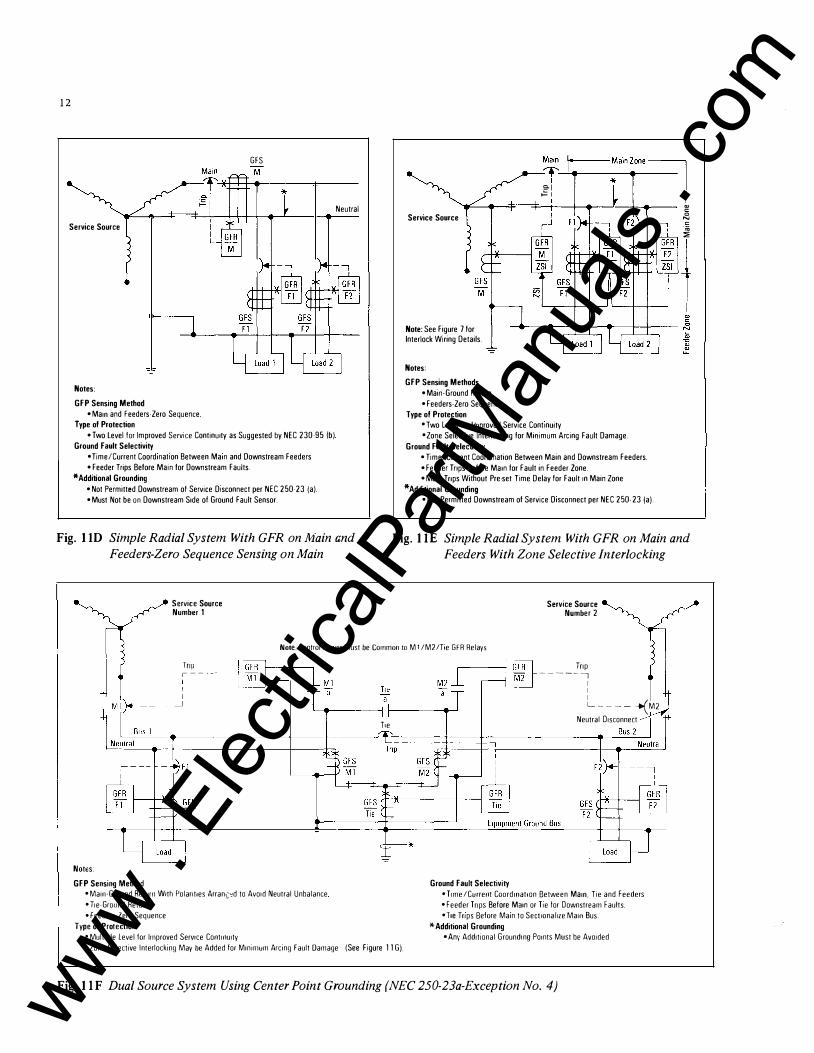
Notes:
GFP Sensing Method •Mam and Feeders-Zero Sequence
Type of Protection •Two level for Improved Serv1ce Continuity as Suggested by NEC 230-951b)
Ground Fault Selectivity • Time/Current Coordmat1on Between Mam and Downstream Feeders • Feeder Trips Before Main for Downstream Faults.
*Additional Grounding •Not Permitted Downstream of Service Disconnect per NEC 250-23ia) • Must Not be on Downstream S1de of Ground Fault Sensor.
Neutral Service Source
Note: See Figure 7 lor Interlock Wiring Details.
Notes:
GFP Sensing Methods •Mam-Ground Return. • Feeders-Zero Sequence
Type of Protection • Two level lor Improved Service Cont1nuity • Zone Selective Interlocking lor Minimum Arcing Fault Damage.
Ground Fault Selectivity •Time/Current Coordmation Between Main and Downstream Feeders. • Feeder Tnps Before Mam lor Fault in Feeder Zone •Mam Tnps Without Pre-set Time Delay lor Fault 1n Main Zone
*Additional Grounding •Not Permitted Downstream of Service DISconnect per NEC 250-23ia).
� " 0
N "
�
1
Fig. liD Simple Radial System With GFR on Main and
Feeders-Zero Sequence Sensing on Main
Fig. liE Simple Radial System With GFR on Main and
Feeders With Zone Selective Interlocking
Service Source Number 1
Service Source Number 2
Note: Control Power Must be Cornman toM 1 /M2/Tte GFR Relays
Tnp ,--- Tnp -----, I I I L---- �M2
T1e
'----�.---------+---+----�-------Neutral Disconnect
Notes: GFP Sensing Method
• Ma1n-Ground Return With Polar1t1es Arran:::�d to Avo1d Neutral Unbalance
• Tie-Ground Return
• Feeders-Zero Sequence
Type of Protection • Multiple level for Improved Serv1ce Cont1nu1ty
•Zone Select1ve lnterlock1ng May be Added for MmmlUm Arcmg Fault Damage !See F1gure llG).
Ground Fault Selectivity •T1me/Current Coardmatlon Between Mam. T1e and Feeders •Feeder Tnps Before Mam or T1e lor Downstream Faults • T1e Tnps Before Mam to Sect1onal1ze Ma111 Bus.
*Additional Grounding • An1· Additional Grounding Pomts Must be Avo1ded
Fig. llF Dual Source System Using Center Point Grounding (NEC 250-23a-Exception No. 4) www . El
ectric
alPar
tMan
uals
. com
GFR iiii1 8 I 9 110 111 I I
I
CD
cp � v
�� r------< I
CDI �# Tie.-� cs b ;r
I Typical Bus 1 Feeder I
L __ -; GFR
F1
�1 a -
n
GFR -Tie
8j9 L10j11
ll Tie
-:ra
n0 1M2 -,a 1-----, CD: �� Tie
__
b7 Tie +
-"CS I I
1-----_j
GFR -M2
8 I 9 110 111 I I
- CD Typical Bus 2 Feeder
GFR F2
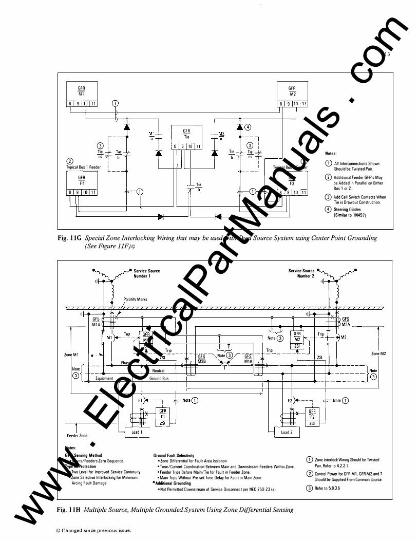
Notes:
(j) All Interconnections Shown Should be Twisted Pair.
CD Additional Feeder GFR's May be Added in Parallel on Either Bus 1 or 2.
13
8 I 9 110 111 <T I I �� 8 I 9llOJ11
_jl @ Add Cell Switch Contacts When
Tie is Drawout Construction. I v 0 Steering D iodes
lo...l l..oll II"'"" I � (Similar to 1N457)
Fig. l lG Special Zone Interlocking Wiring that may be used with Dual Source System using Center Point Grounding
(See Figure llF)©
lj�
" GF� M1A
I Zone M1 *__)o,
---
Service Source Number 1
;clarity Marks
/ >-tft-' .,r-c�I� I r ZSI
Trip L_ ---zSI ____
Phase Neutral
-
�--�-rr Notef CD - Equipment Ground Bus ,__,
FeeJr Zone
Notes:
GFP Sensing Method Ground Fault Selectivity
l w
Gi's�,NoteG)r-Gi's M2s �:;.- MlB
T
• Mams/Feeders-Zero Sequence. • Zone Differential for Fault Area IsolatiOn.
-
-1-iT '--"--
Service Source Number 2 1Jj-<
L _
(fhlGFR Tnp
-� ���� Note@ M2 -r---t -/M2
ZSI I �P _____ _ j ZoneM
ZSI
F2 )4---i <F-Note (j)
��!: m load 2 I
Type of Protection • T1me/Cunent Coordmat1on Between Main and Downstream Feeders W1thm Zone. (j) Zone Interlock Wiring Should be Twisted
Pa1r. Refer to 4.2.2.1. •Two level for Improved Service ContinUity • Zone Select1ve Interlocking for Minimum
Arcing Fault Damage
• Feeder Tnps Before Main/Tie for Fault in Feeder Zone. •Main Trips Without Pre-set Time Delay for Fault 1n Main Zone
*Additional Grounding • Not Permitted Downstream of Service Disconnect per NEC 250-23(a)
Fig. l lH Multiple Source, Multiple Grounded System Using Zone Differential Sensing
© Changed since previous issue.
CD Control Power for GFR M 1, GFR M2 and T Should be Supplied From Common Source.
@ Refer to 5.8.3.6
www . El
ectric
alPar
tMan
uals
. com
14
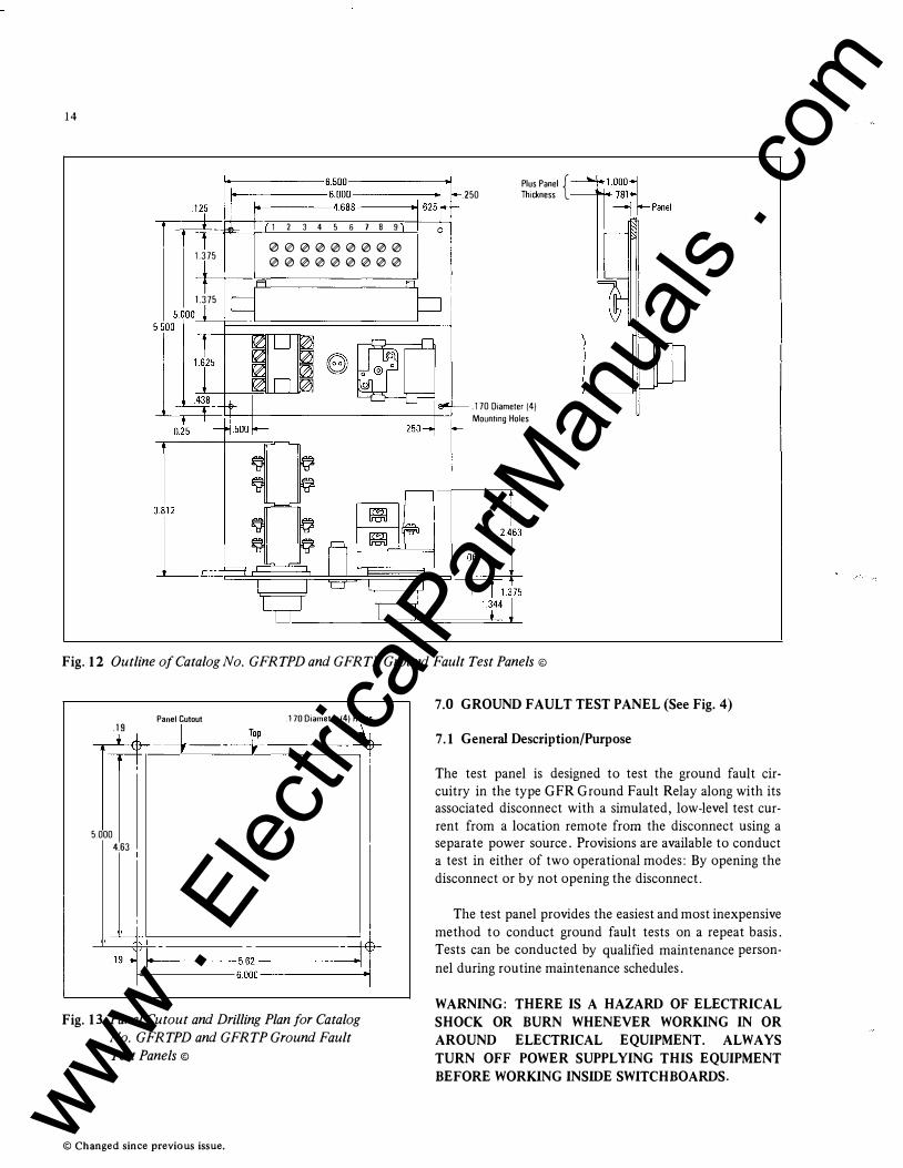
f------6.500---------..1 t-------6.000---------.j
1+-----4.688----..1 .250
Plus Panel { Thickness
1.375
1.375
1 2 3 4 5 6 7 8 9
t2Hb0000000 000000000
.170 Diameter (4) Mounting Holes
Fig. 12 Outline of Catalog No. GFRTPD and GFRTP Ground Fault Test Panels©
Panel Cutout .1s I "
-.-.L-.EJ•A-:r---t ------i-�r� .170 Diameter (4) �
5.000 4.63
I f------:��0------jf Fig. 13 Panel Cutout and Drilling Plan for Catalog
No. GFRTPD and GFRTP Ground Fault
Test Panels ©
© Changed since previous issue.
7.0 GROUND FAULT TEST PANEL (See Fig. 4)
7.1 General Description/Purpose
The test panel is designed to test the ground fault circuitry in the type GFR Ground Fault Relay along with its associated disconnect with a simulated, low-level test current from a location remote from the disconnect using a separate power source. Provisions are available to conduct a test in either of two operational modes: By opening the disconnect or by not opening the disconnect.
The test panel provides the easiest and most inexpensive method to conduct ground fault tests on a repeat basis. Tests can be conducted by qualified maintenance personnel during routine maintenance schedules.
WARNING: THERE IS A HAZARD OF ELECTRICAL SHOCK OR BURN WHENEVER WORKING IN OR AROUND ELECTRICAL EQUIPMENT. ALWAYS TURN OFF POWER SUPPLYING THIS EQUIPMENT BEFORE WORKING INSIDE SWITCHBOARDS.
www . El
ectric
alPar
tMan
uals
. com
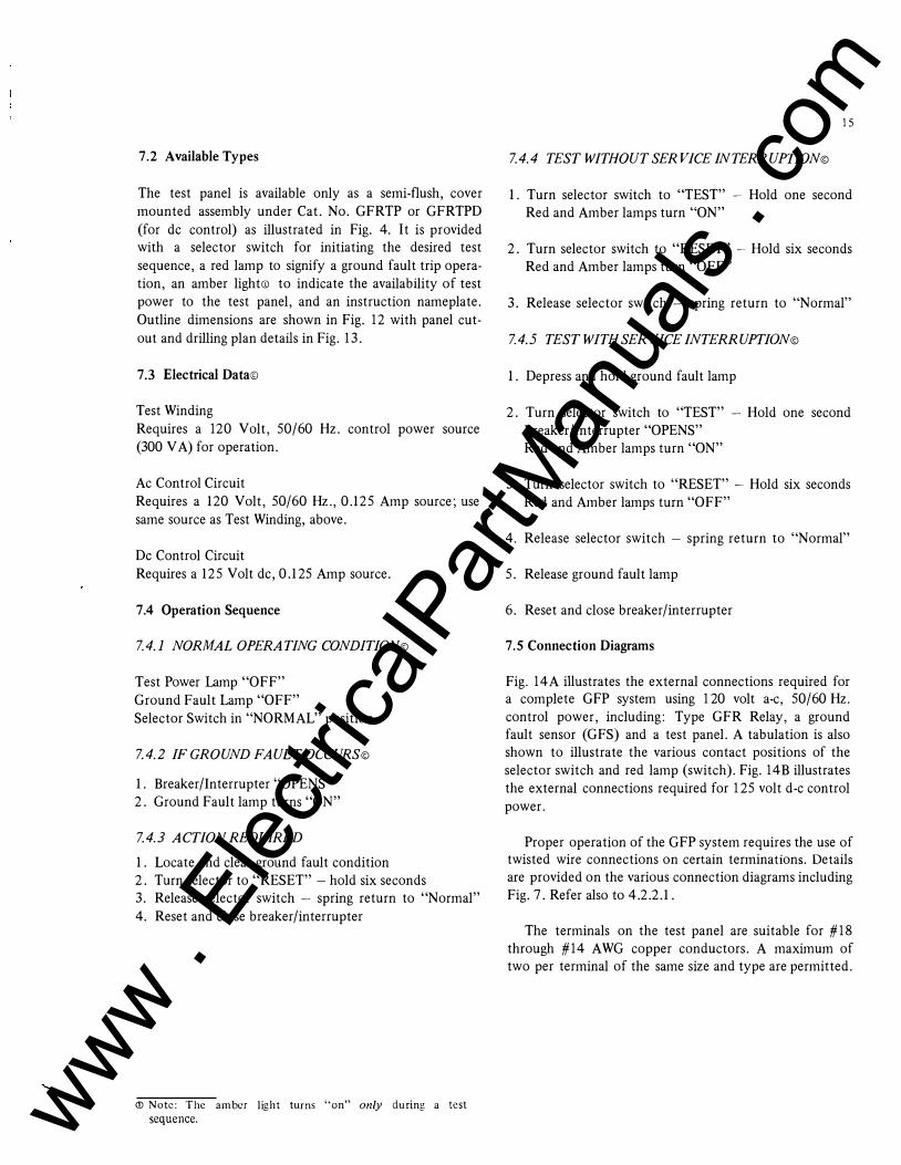
7.2 Available Types
The test panel is available only as a semi-flush, cover mounted assembly under Cat. No. GFRTP or GFRTPD (for de control) as illustrated in Fig. 4. It is provided with a selector switch for initiating the desired test sequence, a red lamp to signify a ground fault trip operation, an amber lighteD to indicate the availability of test power to the test panel, and an instruction nameplate. Outline dimensions are shown in Fig. 12 with panel cutout and drilling plan details in Fig. 13.
7.3 Electrical Data©
Test Winding Requires a 120 Volt, 50/60 Hz. control power source (300 VA) for operation.
Ac Control Circuit Requires a 120 Volt, 50/60 Hz., 0.125 Amp source; use same source as Test Winding, above.
De Control Circuit Requires a 125 Volt de, 0.125 Amp source.
7.4 Operation Sequence
7.4.1 NORMAL OPERATING CONDITION©
Test Power Lamp "OFF" Ground Fault Lamp "OFF" Selector Switch in "NOR MAL" position
7.4.2 IF GROUND FAULT OCCURS©
1. Breaker/Interrupter "OPENS" 2. Ground Fault lamp turns "ON"
7.4.3 ACTION REQUIRED
1. Locate and clear ground fault condition 2. Turn selector to "RESET" - hold six seconds 3. Release selector switch - spring return to "Normal" 4. Reset and close breaker/interrupter
<D Note: The amber light turns "on" only during a test
sequence.
1 5
7.4.4 TEST WITHOUT SERVICE I N T ERR UPTION©
1. Turn selector switch to "TEST" - Hold one second Red and Amber lamps turn "ON"
2. Turn selector switch to "RESET" - Hold six seconds Red and Amber lamps turn "OFF"
3. Release selector switch - spring return to "Normal"
7.4.5 TEST WITH SERVICE INTERRUPTION©
1. Depress and hold ground fault lamp
2. Turn selector switch to "TEST" - Hold one second Breaker/Interrupter "OPENS" Red and Amber lamps turn "ON"
3. Turn selector switch to "RESET" - Hold six seconds Red and Amber lamps turn "OFF"
4. Release selector switch - spring return to "Normal"
5. Release ground fault lamp
6. Reset and close breaker/interrupter
7.5 Connection Diagrams
Fig. 14A illustrates the external connections required for a complete GFP system using 1 20 volt a-c, 50/60Hz. control power, including: Type GFR Relay, a ground fault sensor (GFS) and a test panel. A tabulation is also shown to illustrate the various contact positions of the selector switch and red lamp (switch). Fig. 14B illustrates the external connections required for 1 25 volt d-e control power.
Proper operation of the GFP system requires the use of twisted wire connections on certain terminations. Details are provided on the various connection diagrams including Fig. 7. Refer also to 4.2.2.1.
The terminals on the test panel are suitable for #18 through #14 AWG copper conductors. A maximum of two per terminal of the same size and type are permitted.
www . El
ectric
alPar
tMan
uals
. com
28
Westinghouse El . rom"�'"- - ecfrlc Corporation
c� r�- ).oJ� ()8 ,. ,{"o
;'lft , () . D . o ..
)-t-1 Jf�J.4..
�CI.i A.,
www . El
ectric
alPar
tMan
uals
. com