Embed Size (px)
Citation preview
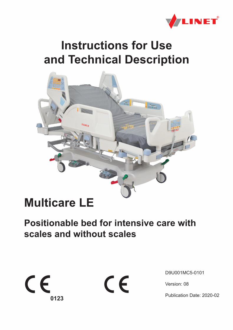
Multicare LEPositionable bed for intensive care with scales and without scales
D9U001MC5-0101
Version: 08
Publication Date: 2020-02
Instructions for Use and Technical Description
D9U001MC5-0101_082
Manufacturer:
LINET spol. s r.o.Želevčice 5274 01 Slaný
Tel.: +420 312 576 111Fax: +420 312 522 668
E-mail: [email protected]://www.linet.comService department: [email protected]
Multicare LEPositionable bed for intensive care with scales and without scales
Author: LINET, s.r.o.Related links: www.linet.com
D9U001MC5-0101Version: 08Publication date: 2020-02
Copyright © LINET, s.r.o., 2020Translation © LINET, 2020All rights reserved.
All trademarks and brands are the property of the appropriate owners. The manufacturer reserves the right to changes in thecontents of the instructions for use that relate to the product´s technical regulations. It is for this reason that the contents of the in-structions for use may indicate differences from the current manufacture of the product. Reproduction, also excerpts, only with prior permission of the publisher. Subject to changes due to technical developments. All technical data are rated data and are subject to construction and manufacturing tolerances.
D9U001MC5-0101_08
3
1 Symbols and Definitions .............................................41.1 Warning Notices ..........................................................41.1.1 Types of Warning Notices ........................................41.1.2 Structure of Warning Notices ...................................41.2 Instructions ..................................................................41.3 Lists .............................................................................41.4 Symbols on the Package ............................................51.5 Symbols and Labels on the Bed .................................61.6 Serial Label with UDI ..................................................91.7 Acoustic signalisation .................................................101.8 Visual signalisation......................................................111.8.1 Mains Power LED (Multiboard, Attendant Control Panel) ..........................................................................................111.8.2 Accumulator Indicator (Multiboard, Attendant Control Pa-nel)....................................................................................111.8.3 Lock LED (Attendant Control Panel) ........................111.9 Definitions ...................................................................121.10 Abbreviations ............................................................132 Safety Instructions .......................................................143 Intended use .................................................................183.1 User population ...........................................................183.2 Contraindications ........................................................183.3 Operator ......................................................................184 Product Description .....................................................195 Technical Specification ...............................................205.1 Identification of Applied Parts (Type B) .......................205.2 Scales (only version with scales) ................................205.3 Mechanical Specifications (Multicare LE) ...................205.4 Environment Conditions ..............................................215.5 Electrical Specifications (Multicare LE) .......................215.6 Electromagnetic compatibility .....................................225.6.1 Manufacturer instructions – electromagnetic emissions ...........................................................................................225.6.2 Manufacturer instructions – electromagnetic susceptibility ..........................................................................................236 Use and Storage Conditions .......................................247 Scope of Delivery and Bed Variants ...........................257.1 Delivery ......................................................................257.2 Scope of Delivery ........................................................257.3 Multicare LE Variants ..................................................258 Putting into Service .....................................................268.1 Accumulator Activation ................................................278.1.1 Placement of Control Section ..................................278.1.2 Removing the Isolating Foil ......................................278.2 Head Board and Foot Board .......................................288.3 Potential Equalisation .................................................298.4 Before Use .................................................................308.5 Transport .....................................................................308.6 Firmware .....................................................................309 Power Supply Cord (Mains Power Cable) ..................3110 Accumulator ...............................................................3110.1 Accumulator Operation .............................................3110.2 Replacing the accumulator .......................................3210.3 Removing the Bed from Use .....................................3310.4 Deactivating the Accumulator ...................................3311 Manipulation ...............................................................3411.1 Siderails .....................................................................3411.2 Castor Control and Bed Transport.............................3511.2.1 Central Castor Control ............................................3511.2.2 Bed transport ..........................................................3511.3 CPR Backrest Release ..............................................3611.4 Control Elements .......................................................3711.4.1 Multiboard in Both Head Siderails ..........................3711.5 Attendant Control Panel ............................................4011.5.1 Handset ..................................................................4211.5.2 Patient Control Panels............................................4211.5.3 Bed Height Foot Control .........................................43
11.5.4 Lateral Tilt Foot Control ..........................................4311.5.5 Quick-Action Panels ...............................................4312 Scales (WS 17) ...........................................................4412.1 Scales Control Panel ................................................4412.1.1 Preparation ...........................................................4412.1.2 Taring .....................................................................4512.1.3 Displaying ..............................................................4512.1.4 Hold Mode ..............................................................4512.1.5 Setting Mode ..........................................................4512.1.6 Bed Exit Alarm .......................................................4612.1.7 Bed Overload .........................................................4612.1.8 Bed Underload .......................................................4612.1.9 Weighing in tilt ........................................................4612.1.10 Zeroing Scales .....................................................4613 Equipment ..................................................................4713.1 Accessory rails ..........................................................4713.2 i-Brake® (optional) ....................................................4713.3 Retractable 5th wheel i-Drive® (optional) .................4713.4 Mobi-Lift® ..................................................................4813.4.1 Using the Support Handles ....................................4813.5 Safety Night Light ......................................................4813.6 i-Drive Power (optional) ............................................4913.6.1 i-Drive Power System - Basic Description .............4913.6.2 Safety instruction for i-Drive Power ........................4913.6.3 Specifications of Use .............................................4913.6.4 Manipulation ...........................................................5013.6.5 Powered Drive .......................................................5113.6.6 Braking ...................................................................5113.6.7 i-Drive Power Activation/Deactivation ....................5213.6.8 Free Drive ..............................................................5213.6.9 Accumulator ...........................................................5213.6.10 Fault Signalization ................................................5313.6.11 Light Indicators .....................................................5313.6.12 Technical Specifications .......................................5313.6.13 Electrical specification ..........................................5313.6.14 I-Drive Power Maintenance ..................................5413.7 X-Ray Lung Examination ..........................................5413.7.1 Necessary Steps before the Examination ..............5413.7.2 Examination with C-arm .........................................5414 Mattress ......................................................................5514.1 Passive Mattress .......................................................5514.1.1 Straps with side release buckles ............................5514.2 Active Mattress (not integrated) ................................5614.3 Symbioso (integrated mattress) ................................5614.3.1 Mattress Control Panel ..........................................5715 Accessories ................................................................5815.1 Lifting Pole ................................................................5815.2 Infusion Stands .........................................................5915.3 Stabilising Pads ........................................................5915.4 Ventilation Circuit Holder ...........................................6015.5 Monitor Tray .............................................................6015.6 Oxygen Bottle Holders ..............................................6115.7 Protector ...................................................................6216 Cleaning/Disinfection ................................................6316.1 Cleaning (Multicare LE) ............................................6416.1.1 Daily Cleaning ........................................................6416.1.2 Cleaning before Changing Patients .......................6516.1.3 Complete Cleaning and Disinfection ......................6517 Troubleshooting .........................................................6618 Maintenance ...............................................................6718.1 Regular maintenance ................................................6718.2 Spare Parts ...............................................................6718.3 Safety Technical Checks ...........................................6719 Disposal ......................................................................6819.1 Environment Protection .............................................6819.2 Disposal ....................................................................6819.2.1 Within Europe ........................................................6819.2.2 Outside Europe ......................................................6820 Warranty ......................................................................69
Table of Contents
D9U001MC5-0101_084
1 Symbols and Definitions1.1 Warning Notices
1.1.1 Types of Warning NoticesWarning notices are differentiated by the type of danger using the following key words:
► CAUTION warns about the risk of material damage.► WARNING warns about the risk of physical injury.► DANGER warns about the risk of fatal injury.
1.1.2 Structure of Warning NoticesSIGNAL WORDS!Type and source of danger!► Measures to avoid the danger.
1.2 InstructionsStructure of instructions:
► Perform this step.Results, if necessary.
1.3 ListsStructure of bulleted lists:
■ List level 1 □ List level 2 ● List level 3
21 Standards and Regulations ......................................69
D9U001MC5-0101_08
5
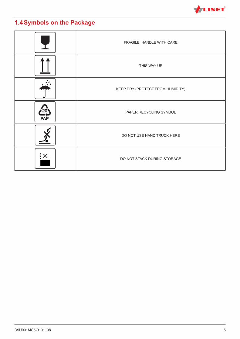
1.4 Symbols on the Package
FRAGILE, HANDLE WITH CARE
THIS WAY UP
KEEP DRY (PROTECT FROM HUMIDITY)
PAPER RECYCLING SYMBOL
DO NOT USE HAND TRUCK HERE
DO NOT STACK DURING STORAGE
D9U001MC5-0101_086
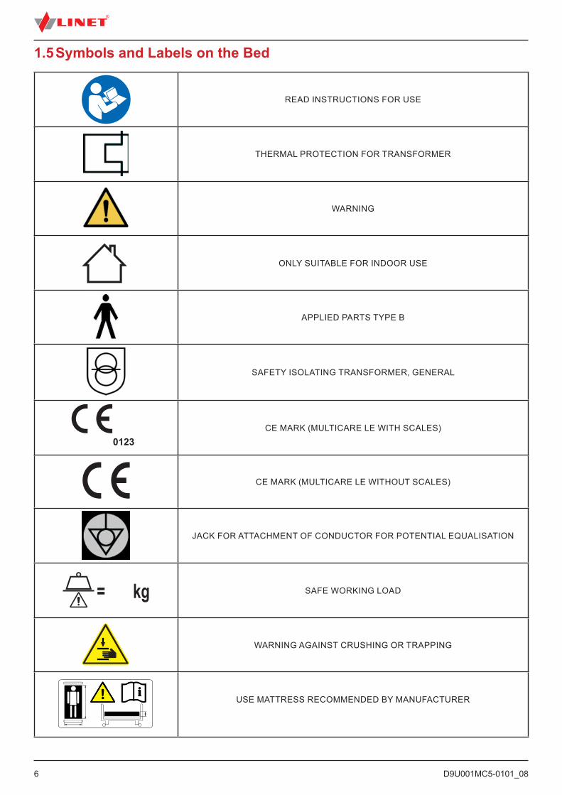
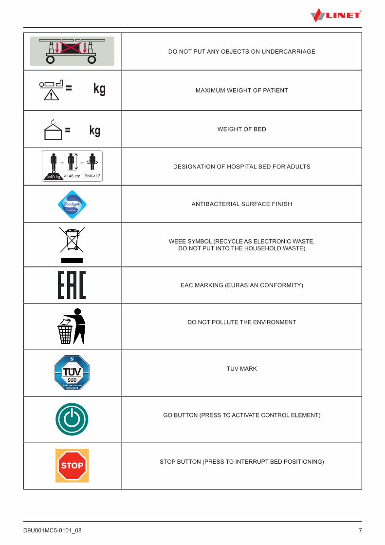
1.5 Symbols and Labels on the Bed
READ INSTRUCTIONS FOR USE
THERMAL PROTECTION FOR TRANSFORMER
WARNING
ONLY SUITABLE FOR INDOOR USE
APPLIED PARTS TYPE B
SAFETY ISOLATING TRANSFORMER, GENERAL
CE MARK (MULTICARE LE WITH SCALES)
CE MARK (MULTICARE LE WITHOUT SCALES)
JACK FOR ATTACHMENT OF CONDUCTOR FOR POTENTIAL EQUALISATION
SAFE WORKING LOAD
WARNING AGAINST CRUSHING OR TRAPPING
USE MATTRESS RECOMMENDED BY MANUFACTURER
D9U001MC5-0101_08
7
DO NOT PUT ANY OBJECTS ON UNDERCARRIAGE
MAXIMUM WEIGHT OF PATIENT
WEIGHT OF BED
DESIGNATION OF HOSPITAL BED FOR ADULTS
ANTIBACTERIAL SURFACE FINISH
WEEE SYMBOL (RECYCLE AS ELECTRONIC WASTE, DO NOT PUT INTO THE HOUSEHOLD WASTE)
EAC MARKING (EURASIAN CONFORMITY)
DO NOT POLLUTE THE ENVIRONMENT
TÜV MARK
GO BUTTON (PRESS TO ACTIVATE CONTROL ELEMENT)
STOP BUTTON (PRESS TO INTERRUPT BED POSITIONING)
D9U001MC5-0101_088
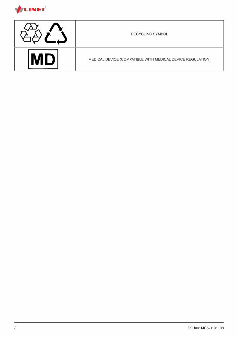
RECYCLING SYMBOL
MEDICAL DEVICE (COMPATIBLE WITH MEDICAL DEVICE REGULATION)
D9U001MC5-0101_08
9
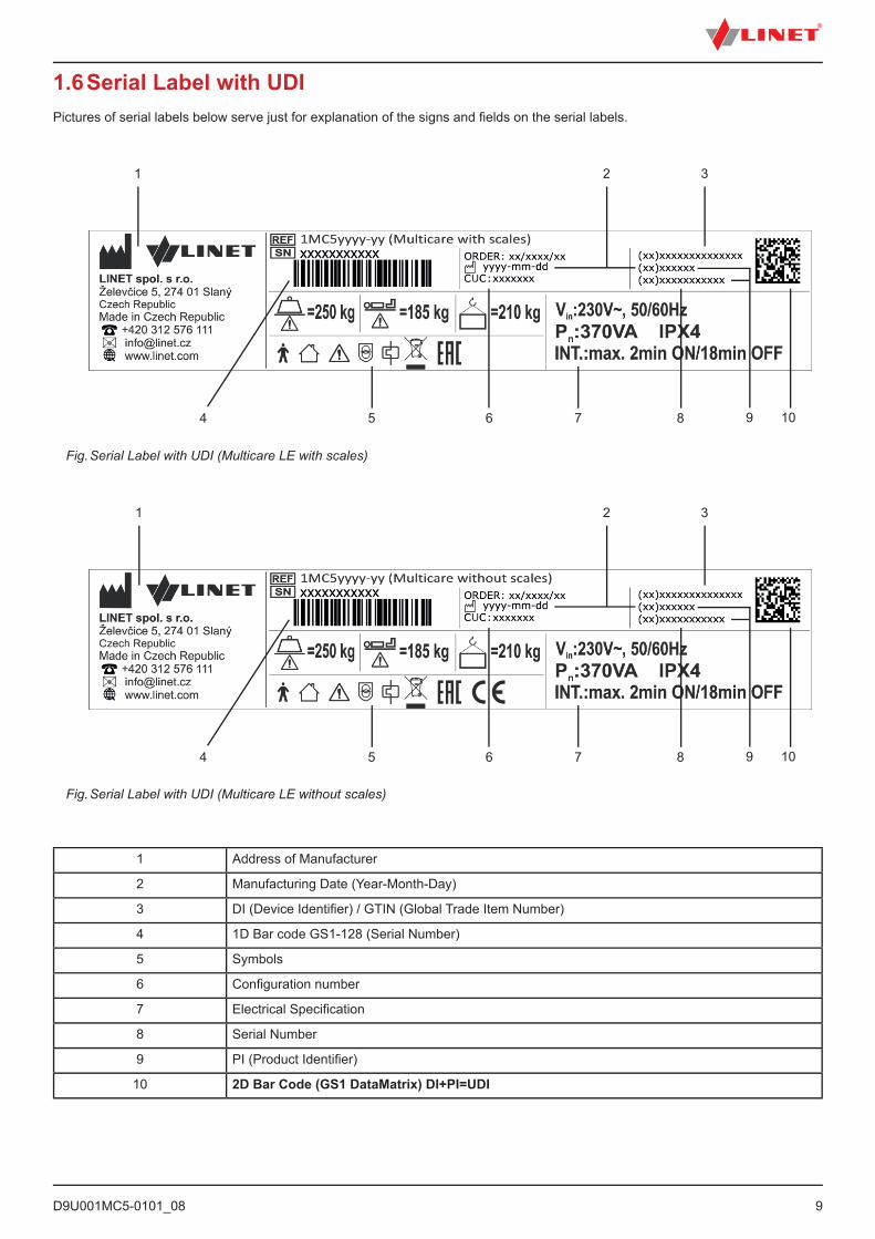
1.6 Serial Label with UDIPictures of serial labels below serve just for explanation of the signs and fi elds on the serial labels.
1 Address of Manufacturer
2 Manufacturing Date (Year-Month-Day)
3 DI (Device Identifi er) / GTIN (Global Trade Item Number)
4 1D Bar code GS1-128 (Serial Number)
5 Symbols
6 Confi guration number
7 Electrical Specifi cation
8 Serial Number
9 PI (Product Identifi er)
10 2D Bar Code (GS1 DataMatrix) DI+PI=UDI
Fig. Serial Label with UDI (Multicare LE with scales)
1
5 6 7 8 9 104
2 3
1
5 6 7 8 9 104
2 3
Fig. Serial Label with UDI (Multicare LE without scales)
D9U001MC5-0101_0810
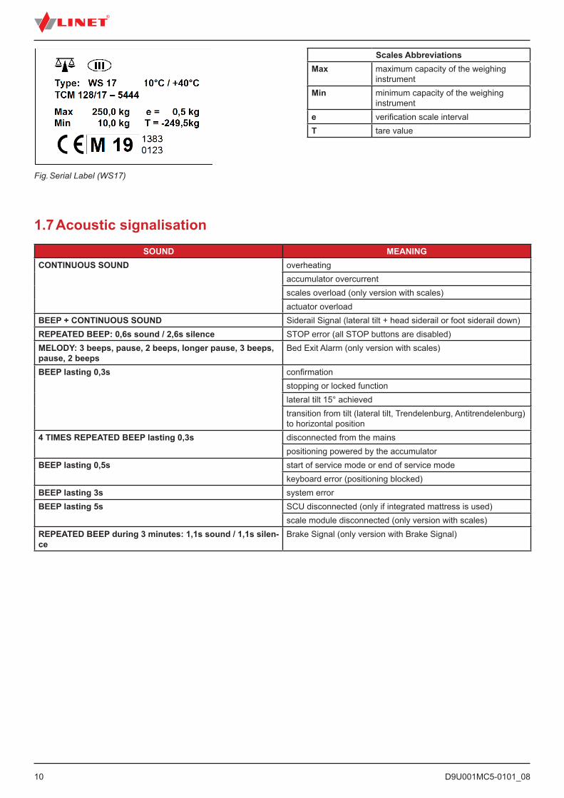
Fig. Serial Label (WS17)
Scales AbbreviationsMax maximum capacity of the weighing
instrumentMin minimum capacity of the weighing
instrumente verification scale intervalT tare value
1.7 Acoustic signalisation SOUND MEANING
CONTINUOUS SOUND overheatingaccumulator overcurrentscales overload (only version with scales)actuator overload
BEEP + CONTINUOUS SOUND Siderail Signal (lateral tilt + head siderail or foot siderail down)REPEATED BEEP: 0,6s sound / 2,6s silence STOP error (all STOP buttons are disabled)MELODY: 3 beeps, pause, 2 beeps, longer pause, 3 beeps, pause, 2 beeps
Bed Exit Alarm (only version with scales)
BEEP lasting 0,3s confirmationstopping or locked functionlateral tilt 15° achievedtransition from tilt (lateral tilt, Trendelenburg, Antitrendelenburg) to horizontal position
4 TIMES REPEATED BEEP lasting 0,3s disconnected from the mainspositioning powered by the accumulator
BEEP lasting 0,5s start of service mode or end of service modekeyboard error (positioning blocked)
BEEP lasting 3s system errorBEEP lasting 5s SCU disconnected (only if integrated mattress is used)
scale module disconnected (only version with scales)REPEATED BEEP during 3 minutes: 1,1s sound / 1,1s silen-ce
Brake Signal (only version with Brake Signal)
D9U001MC5-0101_08
11
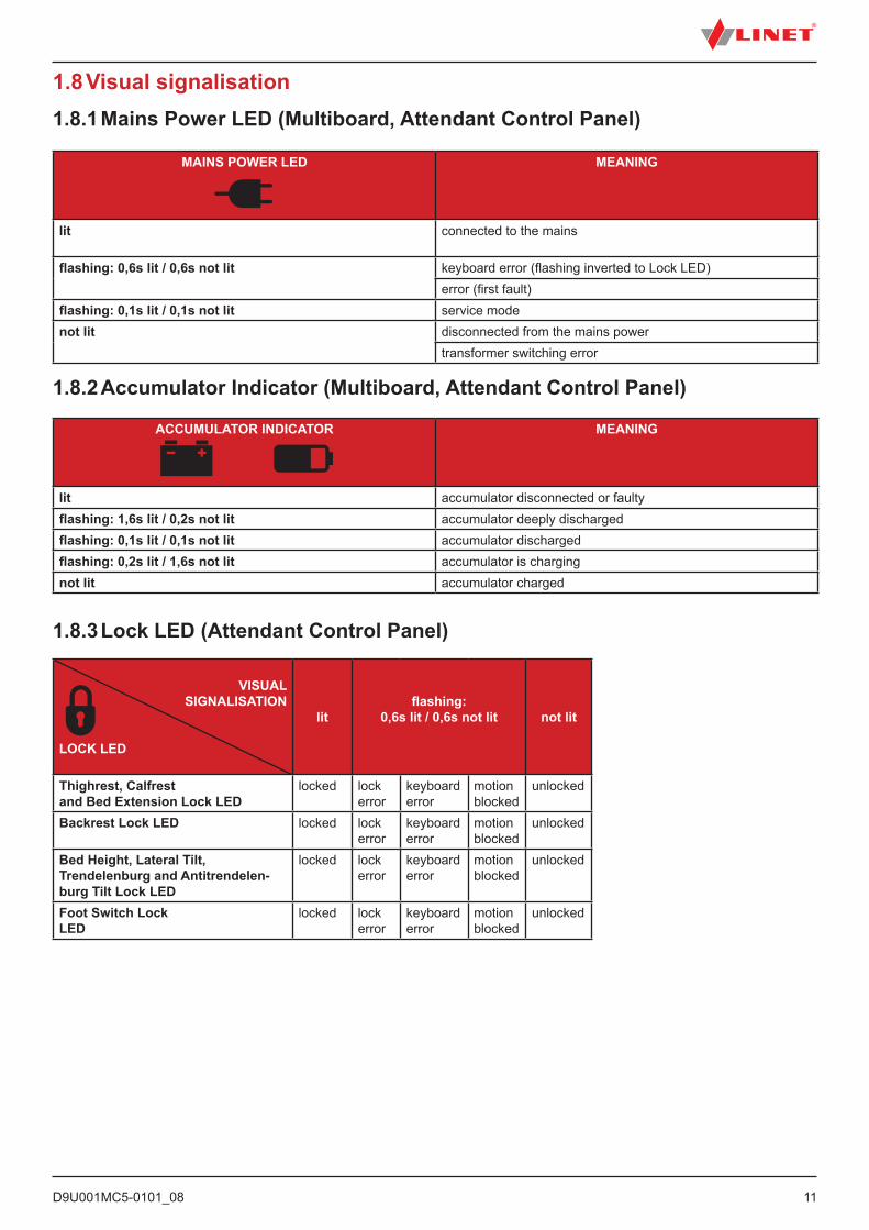
MAINS POWER LED MEANING
lit connected to the mains
flashing: 0,6s lit / 0,6s not lit keyboard error (flashing inverted to Lock LED)error (first fault)
flashing: 0,1s lit / 0,1s not lit service modenot lit disconnected from the mains power
transformer switching error
1.8 Visual signalisation
ACCUMULATOR INDICATOR MEANING
lit accumulator disconnected or faultyflashing: 1,6s lit / 0,2s not lit accumulator deeply dischargedflashing: 0,1s lit / 0,1s not lit accumulator dischargedflashing: 0,2s lit / 1,6s not lit accumulator is chargingnot lit accumulator charged
1.8.1 Mains Power LED (Multiboard, Attendant Control Panel)
1.8.2 Accumulator Indicator (Multiboard, Attendant Control Panel)
VISUAL SIGNALISATION
LOCK LED
litflashing:
0,6s lit / 0,6s not lit not lit
Thighrest, Calfrestand Bed Extension Lock LED
locked lock error
keyboard error
motion blocked
unlocked
Backrest Lock LED locked lock error
keyboard error
motion blocked
unlocked
Bed Height, Lateral Tilt, Trendelenburg and Antitrendelen-burg Tilt Lock LED
locked lock error
keyboard error
motion blocked
unlocked
Foot Switch Lock LED
locked lock error
keyboard error
motion blocked
unlocked
1.8.3 Lock LED (Attendant Control Panel)
D9U001MC5-0101_0812
1.9 DefinitionsBasic Bed Configuration the pricelist model configuration, not including a mattressBed Weight The value depends on the product configuration, accessories or customer
adjustments.Clearance of Undercarriage the height from the floor to the lowest point of the undercarriage between
the castors, for the manipulation of accessories under a braked bed in the standard position
Duty Cycle cycle of operation of the motor: time of activity/time of rest
Ergoframe Ergoframe is the kinematic system of Mattress support platform Adjustment whose effect is the elimination of pressure on the patient´s abdomen and pel-vic area and frictional forces on the patient‘s back and legs.
Maximum Patient Weight Maximum Patient Weight depends on the application environment according to IEC 60601-2-52. For application environment 1 (intensive/critical care) and 2 (acute care) reduce Safe working Load by 65 kg. For application environ-ment 3 (long-term care) and 5 (ambulatory care) reduce Safe working Load by 35 kg.
Safe Working Load the highest allowable load on the bed (patient, mattress, accessories and the load supported by those accessories)
Siderail Height the height of the upper crossbar or the edges of the siderails (not the highest point of the siderail controls) from the patient surface
Standard Bed Position ■ The height of the patient surface with regard to the floor is 400 mm ■ The mattress support platform, including the individual parts, has to be in a horizontal (level - 0°) position. ■ The siderails are always locked in the upper position. ■ The basic position of the integrated extension.
Adult Patient having a physical size equal to or more than 146 cm, a mass equal to or more than 40 kg and a body mass index (BMI) equal to or more than 17 (according to IEC 60601-2-52).
D9U001MC5-0101_08
13
AC ( ~ ) Alternating CurrentCE European ConformityCPR Cardiopulmonary ResuscitationdB Sound Intensity UnitCUC Control Unit Configuration NumberDC ( ) Direct CurrentEAC Euroasian ConformityEMC Electromagnetic CompatibilityFET Field-effect transistorHF High FrequencyHPL High Pressure LaminateICU Intensive Care UnitINT. Duty CycleIP Ingress ProtectionIV IntravenousLED Light Emitting DiodesME Medical Electrical (Equipment)OFF DeactivatedON Activatedppm parts per million, millionth (1000 ppm = 0,1%) REF Reference Number (product type depending on configuration)SCU System Control UnitSN Serial NumberSWL Safe Working LoadUDI Unique Device Identification (for medical devices)USB Universal Serial BusWEEE Waste Electrical and Electronic Equipment
1.10 Abbreviations
D9U001MC5-0101_0814
2 Safety InstructionsWARNING!Multicare LE bed should be left in its lowest position when the patient is unattended in order to reduce risk of injury due to falls!
WARNING!Siderails of Multicare LE should be located in the „up“ position to reduce the risk of the patient accidentally slipping or rolling off the mattress!
WARNING!Incompatible siderails and mattresses can cause an entrapment hazard!
WARNING!Inappropriate handling of the power supply cord, e. g. by kinking, shearing or other mechanical damages is hazardous!
WARNING!When routing cables from other equipment in the Multicare LE bed avoid squeezing those between parts of the Multicare LE bed!
WARNING!Multicare LE bed should not be used with bed hoists and bed lifts!
WARNING!To avoid risk of electric shock, this equipment must only be connected to a supply mains with protective earth.
WARNING!No modification of this equipment is allowed.
WARNING!The bed is intended for adults.► Follow chapter Specifications of Use.
WARNING!Incompatible mattresses can create hazards.
WARNING!To avoid the risk of electric shock, this equipment must only be connected to a supply mains with protective earth.
WARNING!Do not modify this equipment without authorization of the manufacturer.
D9U001MC5-0101_08
15
WARNING!If this equipment is modified, appropriate inspection and testing must be conducted to ensure continued safe use of the equipment.
WARNING!An additional multiple socket-outlet or extension cord shall not be connected to the medical electrical system.
WARNING!During specific investigations or treatments the significant risks of reciprocal interference posed by ME equip-ment may occur.
WARNING!Staff expert assessment is needed to consider all individual cases of contraindications!
WARNING!Certain bed positions are not suitable for specific diagnosis/medical conditions. Fowler position is not suitable for spinal cord injuries! Trendelenburg position is not suitable for patients with higher intracranial pressure!
WARNING!Length adjustment of the bed must be proportional to the height of patient! Risk of trapping or squeezing because of patient´s body constitution disproportionate to the size of mattress support platform!
WARNING!Any serious incident that has occurred in relation to the device should be reported to the manufacturer and the competent authority of the Member State in which the user and/or patient is established!
WARNING!Only authorised and trained person using the tool is allowed to change fuses and power supplies!
WARNING!This medical device is not intended for oxygen enriched environment!
WARNING!This medical device is not intended for use with flammable substances!
WARNING!This medical device is not portable medical electrical equipment!
WARNING!Make sure the duty cycle (2 min ON/18 min OFF) is not exceeded during bed positioning!
WARNING!Patient is allowed to use selected control elements only if hospital personnel had assessed that the patient´s physical and psychological state is in accordance with use of them and only if the hospital personnel had trained the patient in accordance with the instructions for use!
D9U001MC5-0101_0816
WARNING! Hospital personnel is allowed to use the weighing system (scales) for weighing patients only if they had been trained according to the instructions for use!
WARNING!Risk of injury due to incorrect use!Do not use CLP mode for patients undergoing cervical traction.Before placing a patient on a Symbioso, always have a qualified person perform a risk assessment to ensure that the support provided is appropriate and fulfils the applicable local stipulations.
► Follow the instructions carefully.► Only use the bed if it is in perfect working order. If necessary, check the bed functions daily or at each shift change.► Use the bed only with the correct mains supply.► Ensure that the bed is operated exclusively by qualified personnel who have been trained according to the instructions for use.► Ensure that the patient (health permitting) has been informed about the operation of the bed and all applicable safety instructions.► Move the bed only on even, hard-surfaced floors.► Replace any damaged parts immediately with original spare parts.► Ensure that maintenance and installation are performed only by qualified personnel trained by the manufacturer.► Do not apply excess weight or loads to the bed according to SWL (safe working load).► During peak loads or unavoidable excess loads (CPR), place mattress platform in the lowest position.► Ensure that only one adult patient uses the bed at any time.► Take care to avoid injuries or squeezing when operating moving parts.► When using lifting poles or infusion stands, ensure that nothing will be damaged when you move or adjust the bed.► Ensure that the castors are locked when the bed is occupied.► Keep the mattress platform in the lowest position at any time when the healthcare personnel are not treating the patient in order to prevent the patient from falling or injuries.► Ensure that siderails are operated only by healthcare personnel.► Never use the bed in areas where there is a hazard of explosion.► Enable or disable functions on patient controls using the Attendant Control Panel as appropriate for the patient’s physical and mental state. Verify that the function is actually disabled.► Never handle the mains plug with wet hands.► Unplug the mains cable only by pulling on the plug.► Position the mains cable so that there are no loops or bends in the cable; protect the cable from mechanical wear and tear. Improper handling of mains cable can cause an electric shock hazard, other serious injuries or damage to the mattress replacement system.► Improper handling of mains cable can cause an electric shock hazard, other serious injuries or damage the bed.► Ensure that the stipulated duty cycle (on-time) is not exceeded.► Ensure that the moving parts of the bed are not blocked.► To prevent failures, use the manufacturer’s original accessories and mattresses only.► If the patient‘s condition could lead to an entrapment, leave the mattress support platform in the flat position while the patient is unattended.► Adjust bed height to approx. 20 cm below maximum height when transporting the bed in order to facilitate overcoming possible obstacles.► Do not exceed maximum load of 80 kg for mattress platform extension.► Ensure that the bed and its components are only modified with the manufacturer´s approval.► Use the mattress system only as specified in the instructions for use and in perfect working order.► Use the mattress system only with the correct mains supply (see Electrical Specifications (Symbioso)).► Use the mattress system only in its original state and do not modify it in any way.► Have the mattress system used only by or under supervision of trained and qualified nursing personnel.► Have the mattress system serviced and installed only by qualified personnel trained and authorised by the manufacturer.► Do not exceed the maximum patient weight limit (see Mechanical Specifications (Symbioso)).► Do not use the SCU near flammable gases. This does not apply to oxygen cylinders.► Never use the mattress replacement system near radiators or other heat sources.
D9U001MC5-0101_08
17
► Never cover the SCU while in use.► Select a suitable location for the placement of bed accessories and other objects to prevent involuntary activation of buttons or controls which may result in the adjustment of bed positioning.► Do not use the bed in the event parts have been removed (e.g. parts of mattress platform) unless these parts are de signed to be removed (e.g. head and/ or foot end of the bed).► Never place any accessories or handset on the siderails in the area where the integrated siderail controller is located.► After each emergency situation always check if any of the controllers (in siderails, hand set or ACP) is not involuntarily pressed by the bed accessories or by the mattress.► The weighing system must be tested at regular intervals and in accordance with the metrological regulations of the relevant country. All testing and certification must be carried out by qualified personnel. The healthcare provider is responsible for ensuring the required testing frequency and testing procedure of the weighing system is carried out.► To avoid injury or crushing, take extra caution when operating any moving parts of the bed.► To avoid unintended activation of moving parts during any use of the bed always check that none of the control elements of the bed is not involuntary pressed by persons, mattress or other objects.
D9U001MC5-0101_0818
3 Intended useThe intended use is the hospitalization of the patient in the intensive and acute care units, which includes above all the following aspects:► Adjustment of the specific positions needed for the preventive reasons, routine nursing, treatments, mobilization, physiotherapy, examinations, sleeping, and relaxation. These positions are further specified and described in the clinical evaluation of this device, together with their potential clinical outcomes and benefits.► Providing the safe environment for the patient during all relevant procedures. The particular requirements on patient safety are the subject of the clinical evaluation, including evaluation of the risk/benefit ratio. The relevant safety issues are the part of the risk management file.► Patient in-bed indoor transport out of the patient room.► Providing the suitable working conditions for the caregivers to perform the routine and specific tasks during the patient hospitalization.► Indicative measurement of the patient weight, used as supportive feature without direct diagnostic effect. It helps staff to assess the general patient status and apply the nutrition and medicaments (valid for the version of the beds with in-bed scales).
3.1 User population► Adult patients (weight >= 40 kg, height >= 146 cm, BMI >= 17) in the intensive and acute care units (Application Environment 1 and 2 as in IEC 60601-2-52) ► Caregivers (nurses, doctors, technical personnel, transport personnel, cleaning personnel)
3.2 Contraindications► The medical device is not intended for the pediatric patients use.► Certain positions are not suitable for specific diagnoses/medical conditions (e.g. spinal cord injuries vs. Fowler position, higher ICP patients vs. Trendelenburg). Staff expert assessment / nursing consideration is needed in all individual case of contraindication.
3.3 Operator► Caregiver► Patient (based on individual patient status assessment by caregiver the patient can utilize dedicated device functions)
D9U001MC5-0101_08
19
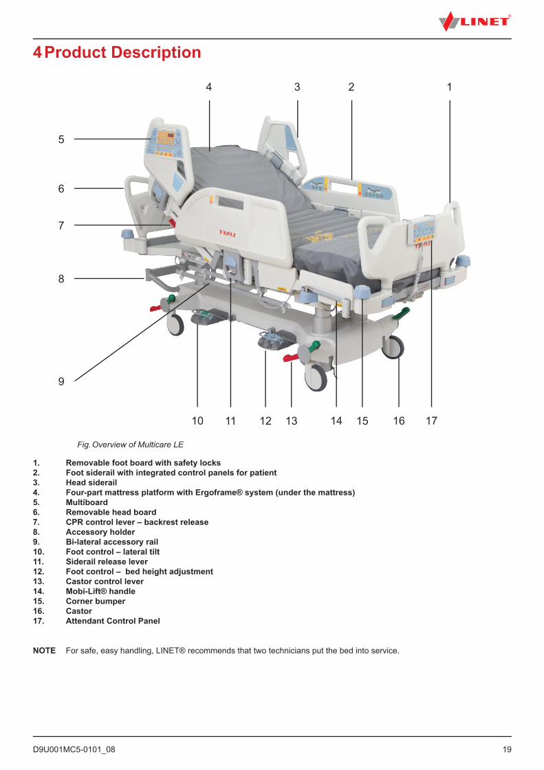
4 Product Description
1. Removable foot board with safety locks2. Foot siderail with integrated control panels for patient 3. Head siderail4. Four-part mattress platform with Ergoframe® system (under the mattress)5. Multiboard6. Removable head board7. CPR control lever – backrest release8. Accessory holder9. Bi-lateral accessory rail10. Foot control – lateral tilt11. Siderail release lever12. Foot control – bed height adjustment13. Castor control lever 14. Mobi-Lift® handle15. Corner bumper16. Castor17. Attendant Control Panel
NOTE For safe, easy handling, LINET® recommends that two technicians put the bed into service.
Fig. Overview of Multicare LE
1234
5
6
7
8
10 11
9
12 13 14 15 16 17
D9U001MC5-0101_0820
5 Technical SpecificationAll technical data are rated data and are subject to construction and manufacturing tolerances.
WARNING!If Multicare LE bed is used with Symbioso integrated mattress replacement system, respect values of mecha-nical and electrical specifications which can harm none of them!
5.1 Identification of Applied Parts (Type B)All part of the bed (and accessories) the patient can reach are type B Applied Parts.
■ Mattress support platform frame, Covers and all Movable Parts■ Head Board and Foot Board■ Siderails■ Mobi-Lift Handles■ Handset
5.2 Scales (only version with scales)Accuracy of displayed weight values:■ 0,5 kg (1,1 lbs)■ Scales Class III
5.3 Mechanical Specifications (Multicare LE)Parameter Value
Dimensions (With Folded-up Siderail) 215 cm x 105 cm Bed Extension 0 cm - 22 cm Recommended Mattress Dimensions 208 cm x 86 cm Maximum Mattress Height 23 cm Bed Height 44 cm - 82 cm Siderail lengthHead sectionCentral section
54 cm 100,7 cm
Castor (Diameter) 15 cmMaximum Backrest Angle 70°Maximum Thighrest Angle 30°Maximum Calfrest Angle 38°Maximum Lateral Tilt Angle 30°Trendelenburg 13°Anti-Trendelenburg Position 16°Siderail Height (above Mattress Platform) 45 cm Bed Weight (Basic Equipment) 224 kg Safe Working Load 250 kg Maximum Lifting Pole Load 75 kg Maximum Patient WeightApplication environment 1, 2Application environment 3, 5
185 kg215 kg
D9U001MC5-0101_08
21
ERGOFRAME
Ergoframe® is the kinematic system of Backrest and Thighrest Adjustment resulting in extension of the Mattress support platform in the seat section. Ergoframe® enlarges the space for pelvic area during Auto-contour. Because of increasement of the space the force applied results in decrease of the pressure that can cause pressure injuries in the pelvic area.
Ergoframe maintains a stable ergonomic position of the body and spine of the patient, thus limiting unwanted movement of the pa-tient by moving down or up in beds. Unified movement eliminates the patient‘s shift over the mattress and thus maintains a uniform position of the patient‘s body that is not bound to the position of the bed parts.
5.4 Environment Conditions
Use ConditionsAmbient Temperature 10°C – 40°CRelative Humidity 30% – 75 %Atmospheric Pressure 795 hPa – 1060 hPa
Storage and Transport ConditionsAmbient Temperature -20°C – 50°CRelative Humidity 20% – 90 %Atmospheric Pressure 795 hPa – 1060 hPa
5.5 Electrical Specifications (Multicare LE)Parameter Value
Input VoltageVersion 1Version 2Version 3 Version 4Version 5Version 6
230 V AC, 50/60 Hz100 V AC, 50/60 Hz110 V AC, 50/60 Hz120 V AC, 50/60 Hz127 V AC, 50/60 Hz110-127 V AC, 50/60 Hz or 230 V AC, 50/60 Hz
Maximum Power Input max. 370 VAIngress Protection IPX4Safety Class Class I (with type B applied parts)Electrical Motor Duty Cycle max. 2 min ON / 18 min OFFAccumulator
FuseVersion 1Version 2
Pb ACCU 2 x 12 V / 1,2 Ah / Fuse 15A
2x T2.0A L 250 V for 230 V version2x T4.0A L 250 V for 100-127 V version
D9U001MC5-0101_0822
5.6 Electromagnetic compatibilityBed is intended for hospitals except for near active HF surgical equipment and the RF shielded room of a medical system for mag-netic resonance imaging, where the intensity of EM disturbances is high.
Bed has defined no essential performance.
WARNING!It is recommended to avoid the use of this device next to or in block with other device, because it could lead to improper operation. If such use is needed, this device and the other equipment should be under surveillance to verify proper operation.
List of used cables:1. Mains cable, maximum length 6 m2. ACP Supervisor control panel, maximum length 3m3. Handset, maximum length 3m
WARNING!Use of the accessories, converters and other cables, than specified and provided by manufacturer of this bed could lead to increase of electromagnetic emission or lower the electromagnetic immunity of this bed and lead to improper operation.
WARNING!Mobile RF communication device (including end use devices like antenna cables and external antenna) should not be used closer than 30 cm (12 inches) from any part of this bed Multicare LE, including cables specified by manufacturer. Otherwise this could lead to deterioration of functionality of this bed.
WARNING!Do not overload the bed (SWL), respect the duty cycle (INT.) and consider chapter 18 Maintenance in order to maintain the basic safety with regard to electromagnetic disturbances for the expected service life.
5.6.1 Manufacturer instructions – electromagnetic emissions
Emission test ComplianceRF emissionsCISPR 11
Group 1
RF emissionsCISPR 11
Class B
Harmonic emissionsIEC 61000-3-2
Class A
Voltage fluctuations / flicker emissionsIEC 61000-3-3
Complies
D9U001MC5-0101_08
23
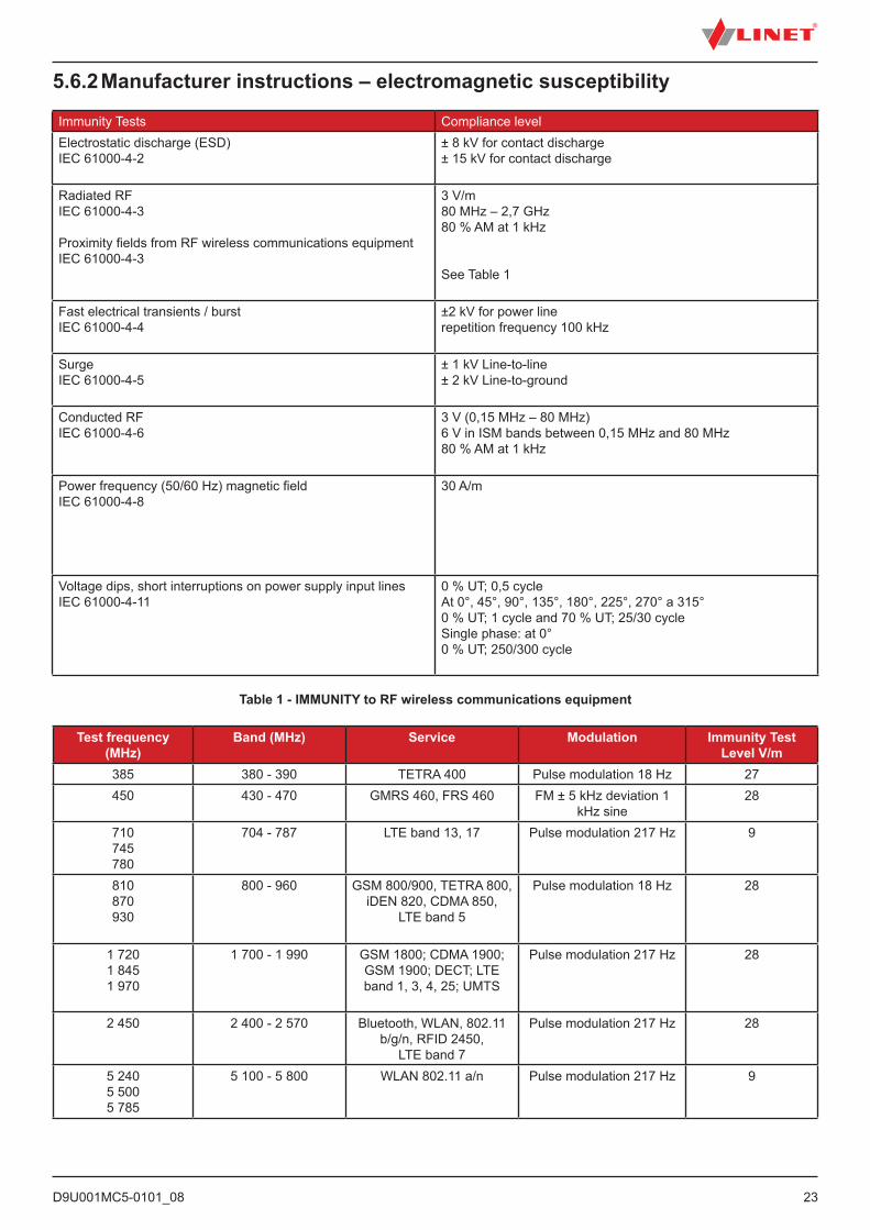
5.6.2 Manufacturer instructions – electromagnetic susceptibility
Immunity Tests Compliance levelElectrostatic discharge (ESD) IEC 61000-4-2
± 8 kV for contact discharge± 15 kV for contact discharge
Radiated RFIEC 61000-4-3
Proximity fields from RF wireless communications equipmentIEC 61000-4-3
3 V/m 80 MHz – 2,7 GHz80 % AM at 1 kHz
See Table 1
Fast electrical transients / burstIEC 61000-4-4
±2 kV for power line repetition frequency 100 kHz
Surge IEC 61000-4-5
± 1 kV Line-to-line± 2 kV Line-to-ground
Conducted RFIEC 61000-4-6
3 V (0,15 MHz – 80 MHz)6 V in ISM bands between 0,15 MHz and 80 MHz80 % AM at 1 kHz
Power frequency (50/60 Hz) magnetic fieldIEC 61000-4-8
30 A/m
Voltage dips, short interruptions on power supply input linesIEC 61000-4-11
0 % UT; 0,5 cycleAt 0°, 45°, 90°, 135°, 180°, 225°, 270° a 315°0 % UT; 1 cycle and 70 % UT; 25/30 cycleSingle phase: at 0°0 % UT; 250/300 cycle
Table 1 - IMMUNITY to RF wireless communications equipment
Test frequency (MHz)
Band (MHz) Service Modulation Immunity Test Level V/m
385 380 - 390 TETRA 400 Pulse modulation 18 Hz 27450 430 - 470 GMRS 460, FRS 460 FM ± 5 kHz deviation 1
kHz sine28
710745780
704 - 787 LTE band 13, 17 Pulse modulation 217 Hz 9
810870930
800 - 960 GSM 800/900, TETRA 800, iDEN 820, CDMA 850,
LTE band 5
Pulse modulation 18 Hz 28
1 7201 8451 970
1 700 - 1 990 GSM 1800; CDMA 1900; GSM 1900; DECT; LTE band 1, 3, 4, 25; UMTS
Pulse modulation 217 Hz 28
2 450 2 400 - 2 570 Bluetooth, WLAN, 802.11 b/g/n, RFID 2450,
LTE band 7
Pulse modulation 217 Hz 28
5 2405 5005 785
5 100 - 5 800 WLAN 802.11 a/n Pulse modulation 217 Hz 9
D9U001MC5-0101_0824
6 Use and Storage ConditionsDANGER!Danger to life due to electric shock!To ensure the bed’s class I protection against electric shocks:► Ground the mains.► Use exclusively Hospital Grade or Hospital Only receptacles for grounding.
CAUTION!Minimal clearance underneath the bed (standard version with 15 cm castors) is 4,4 cm!► Observe the path for any obstacles and avoid collisions and possible damages of any bed´s part on the underca-rriage.► Do not use bed lifts and hoists for lifting the bed (bed hoists for patients are permitted; clearance for the patient
hoists is 15 cm).
Multicare LE with Symbioso are designed for use in rooms for medical purposes. Electrical installations must therefore meet local norms laying down the necessary conditions for electrical installations.► Disconnect the bed from the mains in exceptional cases (i.e. lightning or earthquake).
Multicare LE and Symbioso are not suitable for indoor environments:► containing flammable gases (except oxygen cylinders).
NOTE There are applied no deviations to requirements of IEC 60601-1-2 ed. 4
NOTE There are no known other measures for keeping the basic safety based on EMC phenomena.
NOTE Beds equipped with integration module meet standard for IEEE 802.11 b/g/n (2400,0 MHz – 2483,5 MHz, modulation DSSS (IEEE 802.11 b ), OFDM (IEEE 802.11 g/n) 20MHz bandwidth, EIRP = 0,34 W).
D9U001MC5-0101_08
25
7 Scope of Delivery and Bed Variants7.1 Delivery► Upon receipt, check that the shipment is complete as specified on the delivery note.► Notify the carrier and supplier of any deficiencies or damages immediately as well as in writing or make a note on the delivery note.
7.2 Scope of Delivery■ Multicare LE medical bed■ Mattress with cover - Applied part type B■ SCU (System Control Unit) - Applied part type B■ Instructions for use
7.3 Multicare LE Variantss = standarto = optional
Optional bed features:■ Symbioso □ with Symbioso □ without Symbioso■ Undercarriage of the bed □ Standard undercarriage – under bed clearance under foot columns 44mm (s) □ Higher undercarriage – under bed clearance under foot columns 69mm (o)■ Scales □ with scales (with bed exit alarm)■ Castors □ Tente Integral 150 mm double castors (s) □ Tente Integral 150 mm single castors (o) □ retractable fifth castor (o)■ Control Elements □ Multiboard in both head sections of siderails (s) □ Attendant Control Panel (o) □ handset with adapter for easy connection (Plug and Play) (o) □ handset with illuminated buttons and adapter for easy connection (Plug and Play) (o) □ foot controls – height adjustment (o) □ foot controls – lateral tilt (o) □ patient control elements integrated in both middle sections of the siderails (s) □ variant with no patient controls in siderails (o) □ illuminated patient keyboards (0)■ 1 pair of Mobi-Lift® handles (o)■ i-Brake® (o)■ X-ray cassette holder (o)■ Additional adapter for lifting pole (o)■ Wi-fi/LAN module (o)■ EMR ready bed (o)■ Nurse Call■ i-Drive Power® (o)
D9U001MC5-0101_0826
8 Putting into ServiceWARNING!Risk of injury when working on the bed!► Ensure that the bed is disconnected from the mains connection prior to putting into service, putting out of service
and maintenance.► Ensure that the castors are locked prior to putting into service, putting out of service and maintenance.
CAUTION!Material damage due to incorrect putting into service!► Ensure that putting into service is performed exclusively by manufacturer´s customer service or trained hospital
personnel.
Set up the bed as follows:► Unpack the bed.► Check the delivery (see Scope of Delivery and Bed Variants).► Remove isolating foil from mains control box (see Accumulator Activation).► Install equipment and accessories.► In case of delivery with dismounted head board and foot board, mount the head board and foot board (see Head Board and Foot Board).► Set-up the bed only on a suitable floor surface (see Transport).► Ensure the mains cable does not collide or get stretched when adjusting the bed. Check the plug is inserted correctly.► Do not leave any extension cords or power strips loose on the floor.► Ensure all the required mechanical and electrical prevention mechanisms are available on site.► There is no mains switch on the bed, i.e. the mains cable is the only means to isolate the bed from the mains.► Ensure the mains cable is always accessible.► The plug on the mains cable should only be changed and maintained by qualified and trained service technicians authorised by the manufacturer.
D9U001MC5-0101_08
27
Fig. Control section placement
Fig. Isolating foil
8.1 Accumulator Activation
8.1.1 Placement of Control Section
To remove isolating foil:► Remove isolating foil from mains control box 1 by pulling strap 2.► Check if isolating foil is complete and undamaged.► If isolating foil is damaged, contact the manufacturer’s service department immediately.
NOTE: It is recommended to wear gloves when removing the isolating foil.
8.1.2 Removing the Isolating Foil
D9U001MC5-0101_0828
8.2 Head Board and Foot Board
Dismount the foot board as follows:► Unlock sleeve fittings.► Pull foot board from sleeve fittings.► Lock sleeve fittings.
Install the foot board as follows:► Unlock sleeve fittings.► Slide foot board into sleeve fittings.► Lock sleeve fittings.
Dismount the head board as follows:► Pull head board from sleeve fittings.
Install the head board as follows:► Slide head board into sleeve fittings.
Fig. Foot Board Locks
Fig. Installed Head Board
D9U001MC5-0101_08
29
8.3 Potential EqualisationThe bed is equipped with a standard protective connector. This connector is used for potential equalisation between the bed and any intravascular or intracardiac device connected to the patient to protect the patient from static electric shocks.
Fig. Potential equalisation connector – male
Fig. Potential equalisation connector - female
Use equalisation connector if:■ the patient is connected to any intravascular or intracardiac device.
Before connecting the patient to an intravascular/intracardiac device:► Connect the ground wire of the device to the potential equalisation connector (male) on the bed on which the patient in question is lying.► Use a standard hospital connector (female).► Make sure that the connectors match.► Make sure that there is no possibility for inadvertent disconnection.
Before moving the bed:► Disconnect the patient from the intravascular or intracardiac device.► Disconnect the potential equalisation connector.
D9U001MC5-0101_0830
8.4 Before UsePrepare the bed for service as follows:► Connect the bed to the mains.► Charge the accumulator.► Raise and tilt the mattress platform to the highest position.► Lower and tilt the mattress platform to the lowest position.► Check that the castors as well as main brake work correctly.► Check that the bed extension works correctly.► Check that it is possible to remove the head and foot boards.► Check all of the functions on the control elements (Multiboard etc.).► Check that the siderails function properly.► Dispose of all packaging (see Disposal).
8.5 TransportFor a safe transport, observe the following:► Ensure that no cables are run over when moving a bed.► Ensure that the mains cable is attached with a hook (at the head board).► Ensure that the castors are unlocked before moving the bed during the loading/unloading process (see Castor Control and Bed Transport).► Move the bed exclusively on suitable floor surfaces.
Suitable surfaces:■ Tile■ Hard linoleum■ Poured flooring
Unsuitable surfaces:■ Too soft, unsealed or defective flooring■ Soft wooden flooring■ Soft and porous stone floors■ Carpeted floors with underlay■ Soft linoleum ► For longer distances, ensure that the castor steering function (main control) is activated. ► Ensure that the brakes are released while moving the bed.
8.6 FirmwareThe bed includes firmware that can be updated only by an authorised service technician.This firmware is protected against unauthorised access by mechanical housing (tool is needed to access), by seal (com-ponents with processor are sealed), by exclusive compatibility with an authorised software tool and by check of compati-bility of the new firmware with the bed.
D9U001MC5-0101_08
31
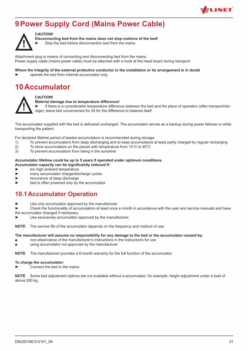
9 Power Supply Cord (Mains Power Cable)CAUTION!Disconnecting bed from the mains does not stop motions of the bed!► Stop the bed before disconnection bed from the mains.
Attachment plug is means of connecting and disconnecting bed from the mains.Power supply cable (mains power cable) must be attached with a hook at the head board during transport.
Where the integrity of the external protective conductor in the installation or its arrangement is in doubt► operate the bed from internal accumulator only.
10 AccumulatorCAUTION!Material damage due to temperature difference!► If there is a considerable temperature difference between the bed and the place of operation (after transport/sto-rage), leave bed unconnected for 24 for the difference to balance itself.
The accumulator supplied with the bed is delivered uncharged. The accumulator serves as a backup during power failures or while transporting the patient.
For declared lifetime period of leaded accumulators is recommended during storage:1) To prevent accumulators from deep discharging and to keep accumulators at least partly charged by regular recharging2) To store accumulators on the places with temperature from 10°C to 40°C3) To prevent accumulators from being in the sunshine
Accumulator lifetime could be up to 5 years if operated under optimum conditions.Accumulator capacity can be significantly reduced if:► too high ambient temperature► many accumulator charge/discharge cycles► recurrence of deep discharge► bed is often powered only by the accumulator
10.1 Accumulator Operation► Use only accumulator approved by the manufacturer.► Check the functionality of accumulators at least once a month in accordance with the user and service manuals and have the accumulator changed if necessary.► Use exclusively accumulator approved by the manufacturer.
NOTE The service life of the accumulator depends on the frequency and method of use.
The manufacturer will assume no responsibility for any damage to the bed or the accumulator caused by:■ non-observance of the manufacturer’s instructions in the instructions for use■ using accumulator not approved by the manufacturer
NOTE The manufacturer provides a 6-month warranty for the full function of the accumulator.
To charge the accumulator:► Connect the bed to the mains.
NOTE Some bed adjustment options are not available without a accumulator, for example, height adjustment under a load of above 200 kg.
D9U001MC5-0101_0832
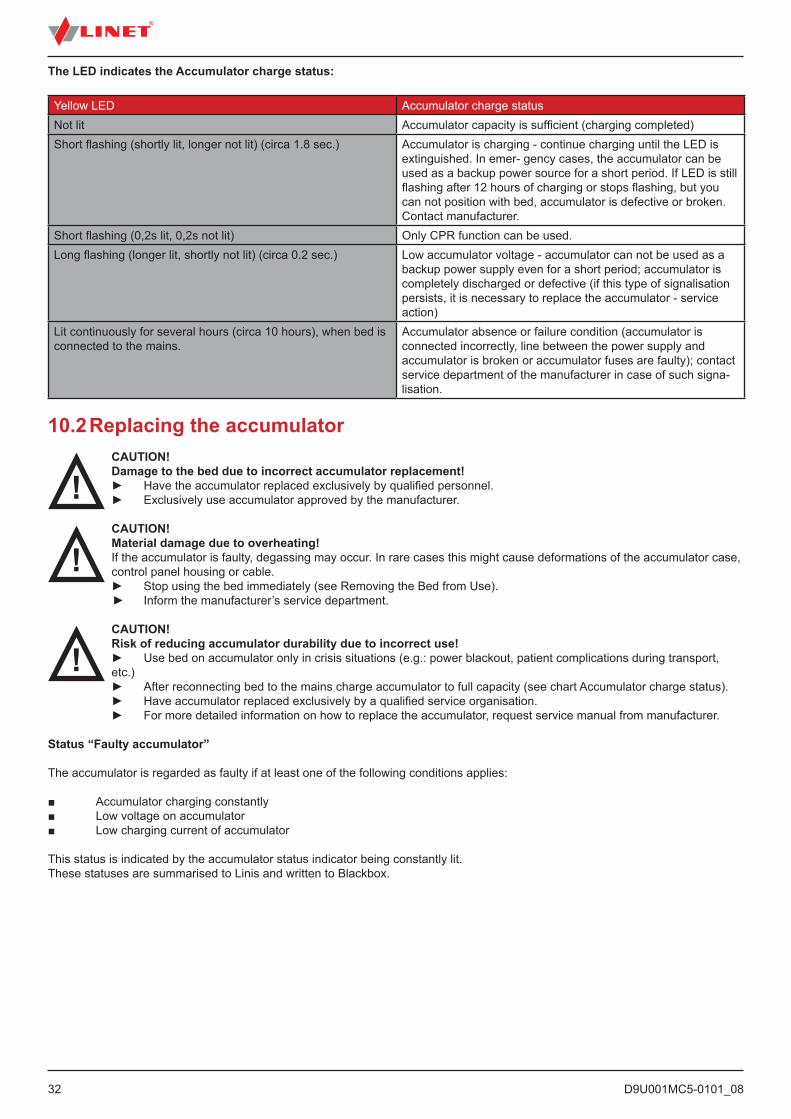
The LED indicates the Accumulator charge status:
Yellow LED Accumulator charge statusNot lit Accumulator capacity is sufficient (charging completed)Short flashing (shortly lit, longer not lit) (circa 1.8 sec.) Accumulator is charging - continue charging until the LED is
extinguished. In emer- gency cases, the accumulator can be used as a backup power source for a short period. If LED is still flashing after 12 hours of charging or stops flashing, but you can not position with bed, accumulator is defective or broken. Contact manufacturer.
Short flashing (0,2s lit, 0,2s not lit) Only CPR function can be used.Long flashing (longer lit, shortly not lit) (circa 0.2 sec.) Low accumulator voltage - accumulator can not be used as a
backup power supply even for a short period; accumulator is completely discharged or defective (if this type of signalisation persists, it is necessary to replace the accumulator - service action)
Lit continuously for several hours (circa 10 hours), when bed is connected to the mains.
Accumulator absence or failure condition (accumulator is connected incorrectly, line between the power supply and accumulator is broken or accumulator fuses are faulty); contact service department of the manufacturer in case of such signa-lisation.
10.2 Replacing the accumulatorCAUTION!Damage to the bed due to incorrect accumulator replacement!► Have the accumulator replaced exclusively by qualified personnel.► Exclusively use accumulator approved by the manufacturer.
CAUTION!Material damage due to overheating!If the accumulator is faulty, degassing may occur. In rare cases this might cause deformations of the accumulator case, control panel housing or cable.► Stop using the bed immediately (see Removing the Bed from Use).
► Inform the manufacturer’s service department.
CAUTION!Risk of reducing accumulator durability due to incorrect use!► Use bed on accumulator only in crisis situations (e.g.: power blackout, patient complications during transport, etc.)► After reconnecting bed to the mains charge accumulator to full capacity (see chart Accumulator charge status).► Have accumulator replaced exclusively by a qualified service organisation.► For more detailed information on how to replace the accumulator, request service manual from manufacturer.
Status “Faulty accumulator”
The accumulator is regarded as faulty if at least one of the following conditions applies:
■ Accumulator charging constantly■ Low voltage on accumulator■ Low charging current of accumulator
This status is indicated by the accumulator status indicator being constantly lit.These statuses are summarised to Linis and written to Blackbox.
D9U001MC5-0101_08
33
To cancel this status:► Press STOP button.
Status “Discharged accumulator”
The accumulator is regarded as discharged if the following condition is met:
■ Defined decrease of voltage depending on discharging current
■ This status is indicated by the accumulator status indicator flashing quickly.■ The electric CPR position is the only possible position.■ This status will be cancelled automatically when the bed switches to sleep mode.
To cancel this status:► Press STOP button.
10.3 Removing the Bed from UseRemove the bed from service as follows:► Disconnect the bed from the mains.► Disconnect the ground wire.► Deactivate the accumulator.► Remove accessories.
To prevent damage during storage:► Pack or cover the bed and accessories.► Ensure that storage conditions are the same as the operating conditions.
10.4 Deactivating the AccumulatorTo avoid damaging the bed and the environment during storage:► Deactivate the accumulator on the Attendant Control Panel.
To deactivate the accumulator on the supervisor:► Disconnect the bed from the mains.► Disconnect the ground wire.► Activate the keypad by pressing the GO button on the supervisor.► Press the Thighrest Up + Thighrest Down + Trendelenburg Position buttons at the same time and hold them for three seconds.
The accumulator is deactivated.
To activate the accumulator again:► Connect Power Cable to the mains.
D9U001MC5-0101_0834
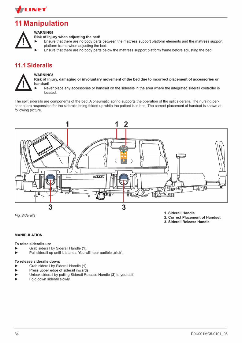
11 Manipulation
11.1 SiderailsWARNING!Risk of injury, damaging or involuntary movement of the bed due to incorrect placement of accessories or handset!► Never place any accessories or handset on the siderails in the area where the integrated siderail controller is
located.
The split siderails are components of the bed. A pneumatic spring supports the operation of the split siderails. The nursing per-sonnel are responsible for the siderails being folded up while the patient is in bed. The correct placement of handset is shown at following picture.
WARNING!Risk of injury when adjusting the bed!► Ensure that there are no body parts between the mattress support platform elements and the mattress support
platform frame when adjusting the bed.► Ensure that there are no body parts below the mattress support platform frame before adjusting the bed.
Fig. Siderails
11
33
2
MANIPULATION
To raise siderails up:► Grab siderail by Siderail Handle (1).► Pull siderail up until it latches. You will hear audible „click“.
To release siderails down:► Grab siderail by Siderail Handle (1).► Press upper edge of siderail inwards.► Unlock siderail by pulling Siderail Release Handle (3) to yourself.► Fold down siderail slowly.
1. Siderail Handle2. Correct Placement of Handset3. Siderail Release Handle
D9U001MC5-0101_08
35
11.2 Castor Control and Bed TransportCAUTION!Material damage due to incorrect transport and involuntary movement!► Prior to transport, ensure that the bed is disconnected from the mains.► Prior to transport, ensure that the auxiliary outlet plug (if available) is disconnected from the mains.► Ensure that the castors are locked prior to assembly, disassembly and maintenance.
► Ensure that the castors are locked when the bed is occupied. ► Hang the mains cable on the appropriate hook on the bed during transport. ► Have the bed transported exclusively by nursing personnel and by at least 2 persons.
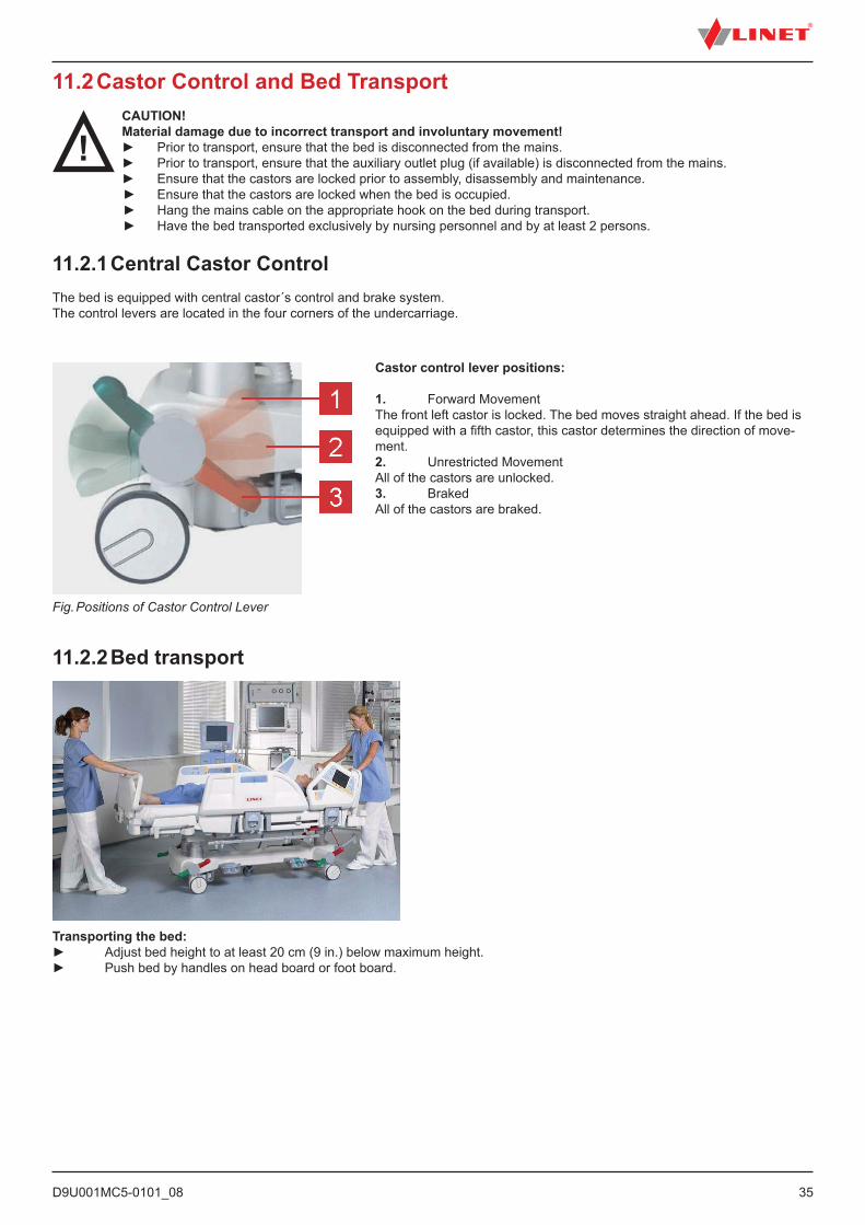
11.2.1 Central Castor ControlThe bed is equipped with central castor´s control and brake system.The control levers are located in the four corners of the undercarriage.
11.2.2 Bed transport
Transporting the bed:► Adjust bed height to at least 20 cm (9 in.) below maximum height.► Push bed by handles on head board or foot board.
Castor control lever positions:
1. Forward MovementThe front left castor is locked. The bed moves straight ahead. If the bed is equipped with a fifth castor, this castor determines the direction of move-ment.2. Unrestricted MovementAll of the castors are unlocked.3. BrakedAll of the castors are braked.
Fig. Positions of Castor Control Lever
D9U001MC5-0101_0836
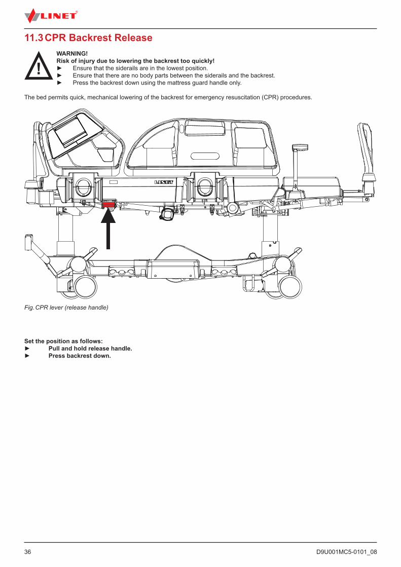
11.3 CPR Backrest ReleaseWARNING!Risk of injury due to lowering the backrest too quickly!► Ensure that the siderails are in the lowest position.► Ensure that there are no body parts between the siderails and the backrest.► Press the backrest down using the mattress guard handle only.
The bed permits quick, mechanical lowering of the backrest for emergency resuscitation (CPR) procedures.
Fig. CPR lever (release handle)
Set the position as follows:► Pull and hold release handle.► Press backrest down.
D9U001MC5-0101_08
37
11.4 Control ElementsThe bed is operated by different control elements.
Control elements depending on the model:■ Multiboard with LCD touchscreen in both head siderails■ Quick-Action panel in both head siderails■ Attendant Control Panel■ Handset■ Handset with adapter for easy connection (Plug and Play)■ Handset with illuminated buttons■ Foot control for lateral tilt■ Foot control for height adjustment■ Patient control elements integrated in both foot siderails
Disabling individual functions on the Multiboard will affect all control elements.
If the bed does not react to individual position settings:► Check whether the function is disabled on the Attendant Control Panel.
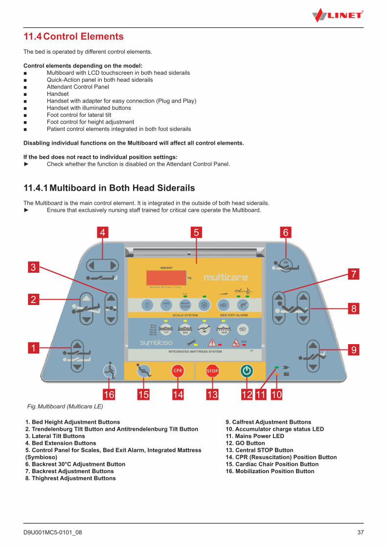
11.4.1 Multiboard in Both Head SiderailsThe Multiboard is the main control element. It is integrated in the outside of both head siderails.► Ensure that exclusively nursing staff trained for critical care operate the Multiboard.
1
2
3
4 5 6
8
7
9
11 101213141516Fig. Multiboard (Multicare LE)
1. Bed Height Adjustment Buttons 2. Trendelenburg Tilt Button and Antitrendelenburg Tilt Button 3. Lateral Tilt Buttons 4. Bed Extension Buttons5. Control Panel for Scales, Bed Exit Alarm, Integrated Mattress (Symbioso) 6. Backrest 30°C Adjustment Button7. Backrest Adjustment Buttons8. Thighrest Adjustment Buttons
9. Calfrest Adjustment Buttons 10. Accumulator charge status LED 11. Mains Power LED12. GO Button13. Central STOP Button 14. CPR (Resuscitation) Position Button15. Cardiac Chair Position Button16. Mobilization Position Button
D9U001MC5-0101_0838
Central STOP Button
The central STOP button immediately interrupts all bed movements in case of unauthorized bed positioning or an electronic failure.Pressing the central STOP button for at least 0.3 seconds immediately stops all electronic bed movements.
Activating GO Button
The GO button activates the keypad or the touchscreens of all control elements.A GO button is included on a number of different control elements. The function of the GO button is identical on all control ele-ments. Pressing a function button will keep the keypad active for another 3 minutes.
During this time the following is possible:■ Adjusting individual mattress platform elements by pressing the corresponding function buttons.■ Disabling individual functions with the lock buttons.
Each time a function button is pressed, the keypad will remain active for another 3 minutes.
Function Buttons
The positioning function buttons 1, 2, 3, 4, 6, 7, 8, 9 and 16 adjust the position of the backrest, thighrest and calfrest as well as the tilting and extending of the mattress platform. The buttons 14 and 15 allow adjusting the Cardiac Chair and CPR positions.
Button CPR (Resuscitation) Position
If the bed is equipped with Symbioso mattress, pressing button 14 will also deflate the mattress.
NOTE Bed positioning which depends on columns is continuous.
NOTE During continuous positioning Backrest stops automatically in 30 and 45 degrees. To continue in positioning press corresponding button once more.
NOTE Pressing two function buttons at the same time will be recognized as an error by the controller. The controller will interrupt immediately all bed movements immediately.
Set the position as follows:► Activate the keypad by pressing the GO button.► Press and hold function button until desired position is reached.
Mains power LED
Status Meaning lit LED connected to the mainsunlit LED disconnected from the mains flashing LED system error
D9U001MC5-0101_08
39
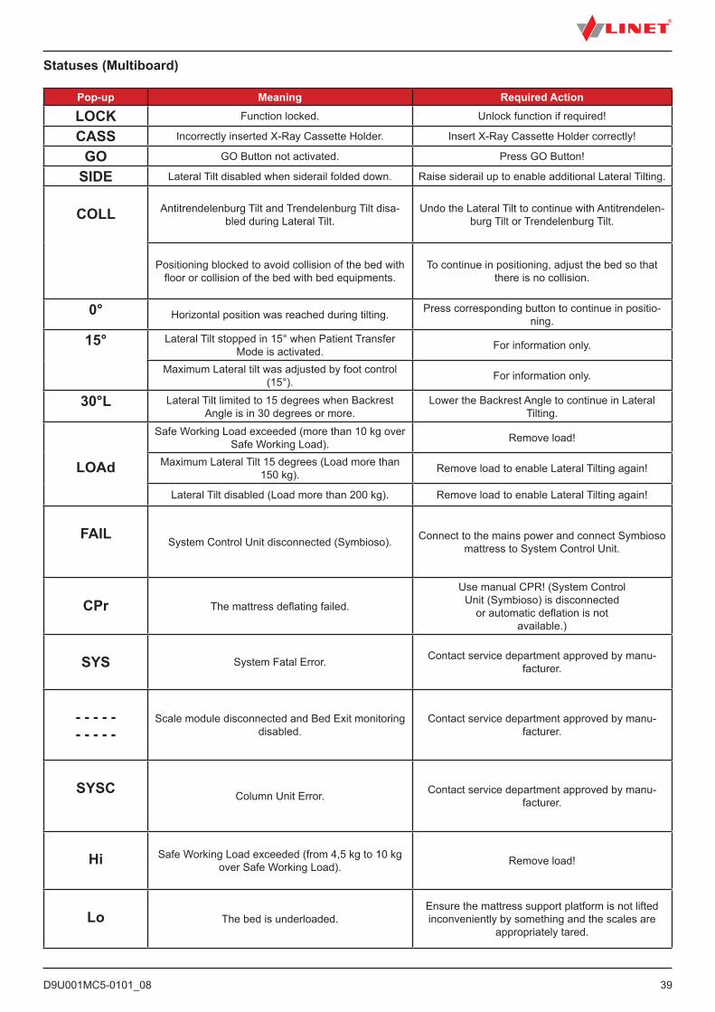
Statuses (Multiboard)
Pop-up Meaning Required Action
LOCK Function locked. Unlock function if required!
CASS Incorrectly inserted X-Ray Cassette Holder. Insert X-Ray Cassette Holder correctly!
GO GO Button not activated. Press GO Button!
SIDE Lateral Tilt disabled when siderail folded down. Raise siderail up to enable additional Lateral Tilting.
COLL Antitrendelenburg Tilt and Trendelenburg Tilt disa-bled during Lateral Tilt.
Undo the Lateral Tilt to continue with Antitrendelen-burg Tilt or Trendelenburg Tilt.
Positioning blocked to avoid collision of the bed with floor or collision of the bed with bed equipments.
To continue in positioning, adjust the bed so that there is no collision.
0° Horizontal position was reached during tilting. Press corresponding button to continue in positio-ning.
15° Lateral Tilt stopped in 15° when Patient Transfer Mode is activated. For information only.
Maximum Lateral tilt was adjusted by foot control (15°). For information only.
30°L Lateral Tilt limited to 15 degrees when Backrest Angle is in 30 degrees or more.
Lower the Backrest Angle to continue in Lateral Tilting.
LOAd
Safe Working Load exceeded (more than 10 kg over Safe Working Load). Remove load!
Maximum Lateral Tilt 15 degrees (Load more than 150 kg). Remove load to enable Lateral Tilting again!
Lateral Tilt disabled (Load more than 200 kg). Remove load to enable Lateral Tilting again!
FAIL System Control Unit disconnected (Symbioso). Connect to the mains power and connect Symbioso
mattress to System Control Unit.
CPr The mattress deflating failed.
Use manual CPR! (System ControlUnit (Symbioso) is disconnected
or automatic deflation is notavailable.)
SYS System Fatal Error. Contact service department approved by manu-facturer.
- - - - - - - - - -
Scale module disconnected and Bed Exit monitoring disabled.
Contact service department approved by manu-facturer.
SYSC Column Unit Error. Contact service department approved by manu-facturer.
Hi Safe Working Load exceeded (from 4,5 kg to 10 kg over Safe Working Load). Remove load!
Lo The bed is underloaded.Ensure the mattress support platform is not lifted inconveniently by something and the scales are
appropriately tared.
D9U001MC5-0101_0840
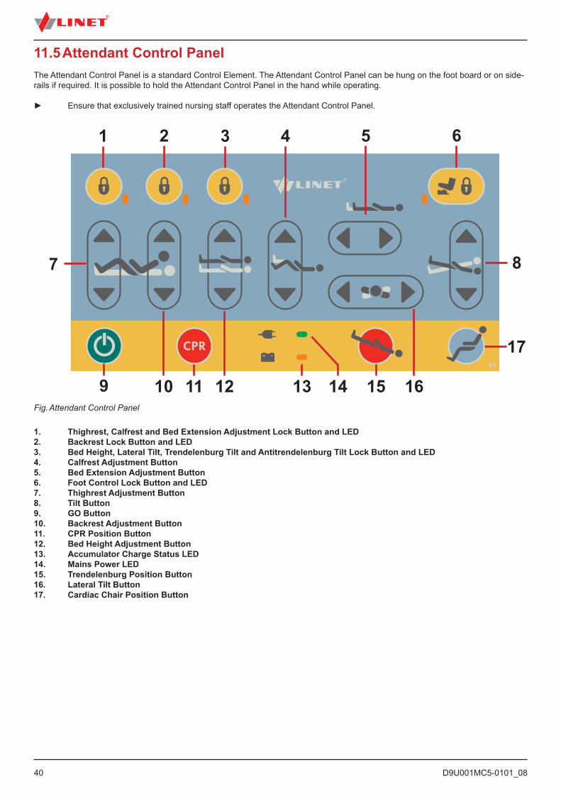
Fig. Attendant Control Panel
1 2 3 4 5 6
8
17
161511 13 1410 129
7
11.5 Attendant Control PanelThe Attendant Control Panel is a standard Control Element. The Attendant Control Panel can be hung on the foot board or on side-rails if required. It is possible to hold the Attendant Control Panel in the hand while operating.
► Ensure that exclusively trained nursing staff operates the Attendant Control Panel.
1. Thighrest, Calfrest and Bed Extension Adjustment Lock Button and LED2. Backrest Lock Button and LED 3. Bed Height, Lateral Tilt, Trendelenburg Tilt and Antitrendelenburg Tilt Lock Button and LED 4. Calfrest Adjustment Button5. Bed Extension Adjustment Button6. Foot Control Lock Button and LED7. Thighrest Adjustment Button8. Tilt Button9. GO Button10. Backrest Adjustment Button 11. CPR Position Button12. Bed Height Adjustment Button13. Accumulator Charge Status LED14. Mains Power LED15. Trendelenburg Position Button16. Lateral Tilt Button17. Cardiac Chair Position Button
D9U001MC5-0101_08
41
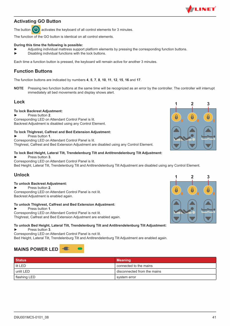
Activating GO ButtonThe button activates the keyboard of all control elements for 3 minutes.
The function of the GO button is identical on all control elements. During this time the following is possible:► Adjusting individual mattress support platform elements by pressing the corresponding function buttons.► Disabling individual functions with the lock buttons.
Each time a function button is pressed, the keyboard will remain active for another 3 minutes.
Function Buttons
The function buttons are indicated by numbers 4, 5, 7, 8, 10, 11, 12, 15, 16 and 17.
NOTE Pressing two function buttons at the same time will be recognized as an error by the controller. The controller will interrupt immediately all bed movements and display shows alert.
Lock
To lock Backrest Adjustment:► Press button 2.Corresponding LED on Attendant Control Panel is lit.Backrest Adjustment is disabled using any Control Element.
To lock Thighrest, Calfrest and Bed Extension Adjustment:► Press button 1.Corresponding LED on Attendant Control Panel is lit.Thighrest, Calfrest and Bed Extension Adjustment are disabled using any Control Element.
To lock Bed Height, Lateral Tilt, Trendelenburg Tilt and Antitrendelenburg Tilt Adjustment:► Press button 3.Corresponding LED on Attendant Control Panel is lit.Bed Height, Lateral Tilt, Trendelenburg Tilt and Antitrendelenburg Tilt Adjustment are disabled using any Control Element.
Unlock
To unlock Backrest Adjustment:► Press button 2.Corresponding LED on Attendant Control Panel is not lit.Backrest Adjustment is enabled again.
To unlock Thighrest, Calfrest and Bed Extension Adjustment:► Press button 1.Corresponding LED on Attendant Control Panel is not lit.Thighrest, Calfrest and Bed Extension Adjustment are enabled again.
To unlock Bed Height, Lateral Tilt, Trendelenburg Tilt and Antitrendelenburg Tilt Adjustment:► Press button 3.Corresponding LED on Attendant Control Panel is not lit.Bed Height, Lateral Tilt, Trendelenburg Tilt and Antitrendelenburg Tilt Adjustment are enabled again.
MAINS POWER LED
Status Meaninglit LED connected to the mainsunlit LED disconnected from the mainsflashing LED system error
1 2 3
1 2 3
D9U001MC5-0101_0842
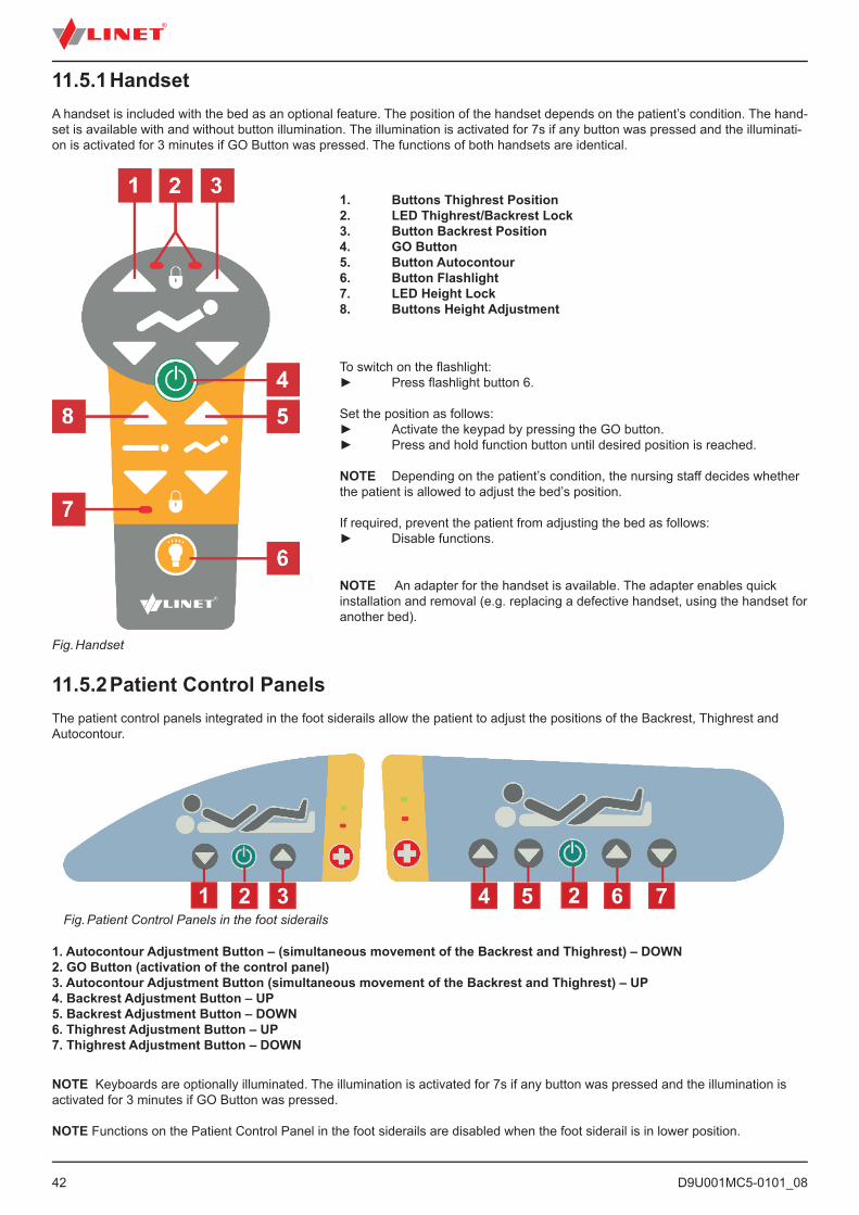
11.5.1 HandsetA handset is included with the bed as an optional feature. The position of the handset depends on the patient’s condition. The hand-set is available with and without button illumination. The illumination is activated for 7s if any button was pressed and the illuminati-on is activated for 3 minutes if GO Button was pressed. The functions of both handsets are identical.
1. Buttons Thighrest Position2. LED Thighrest/Backrest Lock3. Button Backrest Position4. GO Button5. Button Autocontour6. Button Flashlight7. LED Height Lock8. Buttons Height Adjustment
To switch on the fl ashlight:► Press fl ashlight button 6.
Set the position as follows:► Activate the keypad by pressing the GO button.► Press and hold function button until desired position is reached.
NOTE Depending on the patient’s condition, the nursing staff decides whether the patient is allowed to adjust the bed’s position.
If required, prevent the patient from adjusting the bed as follows:► Disable functions.
NOTE An adapter for the handset is available. The adapter enables quick installation and removal (e.g. replacing a defective handset, using the handset for another bed).
11.5.2 Patient Control PanelsThe patient control panels integrated in the foot siderails allow the patient to adjust the positions of the Backrest, Thighrest and Autocontour.
Fig. Patient Control Panels in the foot siderails
1. Autocontour Adjustment Button – (simultaneous movement of the Backrest and Thighrest) – DOWN2. GO Button (activation of the control panel)3. Autocontour Adjustment Button (simultaneous movement of the Backrest and Thighrest) – UP4. Backrest Adjustment Button – UP5. Backrest Adjustment Button – DOWN6. Thighrest Adjustment Button – UP7. Thighrest Adjustment Button – DOWN
1 2 3 4 5 2 6 7
Fig. Handset
NOTE Keyboards are optionally illuminated. The illumination is activated for 7s if any button was pressed and the illumination is activated for 3 minutes if GO Button was pressed.
NOTE Functions on the Patient Control Panel in the foot siderails are disabled when the foot siderail is in lower position.
D9U001MC5-0101_08
43
11.5.3 Bed Height Foot ControlThe foot control is optional and allows setting the height of the bed with one’s feet.
1. Protection Frame against Unwanted Activation2. Foot Switch Raise Mattress Platform3. Foot Switch Examination Position4. Foot Switch Lower Mattress Platform
Set the position as follows:► Press foot switch 2, 3 or 4 to activate foot control.► Press and hold foot switch until desired position is reached.
NOTE: It is possible to activate foot control by pressing GO button on the control elements of the bed then it is not needed to activate the foot control by buttons 2, 3 or 4.
Fig. Foot Control Bed Height
11.5.4 Lateral Tilt Foot ControlThe foot control is optional and allows setting the lateral tilt of the bed with the feet.
1. Protection Frame against Unwanted Activation2. Foot Switch Tilt Right3. Foot Switch GO4. Foot Switch Tilt Left
Set the position as follows:► Activate the keypad by pressing the GO button.► Press and hold foot switch until desired position is reached.
Fig. Foot Switch Lateral Tilt
11.5.5 Quick-Action PanelsThe Quick-Action panels integrated in the head sections of the siderails allow the nursing personnel and the patient to adjust the bed height.
1. Buttons Bed Height Adjustment2. GO Button
Set position as follows:► Activate the keypad by pressing the GO button.► Press and hold function button until desired position is reached.
Fig. Quick-Action Panel
D9U001MC5-0101_0844
12 Scales (WS 17)12.1 Scales Control PanelMulticare LE is equipped with a weighing system that allows weighing the patient in bed. The control panel for this system is part of the Multiboard.
1. Indicated Value Switch Button 2. ZERO/T Button 3. Display4. Weight balance indicator5. WEIGHT/CLEAR Button – cancelling the activated function6. HOLD Button7. Bed Exit Alarm volume Button8. Inner Zone Indicator9. Outer Zone Indicator10. Bed Exit Alarm Button
Fig. Control Panel Scales and Symbioso
12.1.1 Preparation ► Install mattress and accessories to prepare bed before patient admission and using the scales.
CAUTION!Incorrect use of scales due to incomplete preparation!► Before each patient admission tare the scales.
D9U001MC5-0101_08
45
12.1.2 TaringThe taring is done in the range from 5kg to 249,5kg. The taring is used to set “0” on the display before placing the patient on the bed. It is used to show actual weight of the patient.The taring must be done on the unloaded bed without patient. It is recommended to position mattress platform about 20 cm above the lowest position and the mattress platform in the horizontal position.
To tare weight:► Ensure that nothing touches the bed except you.► Press icon 2 (Zero/T) for 0,5 s until the display starts to flash. ► Press icon 2 to confirm taring. The „0“ is shown on the display.Place the patient on the bed.
To cancel taring:► Press icon 5 while taring.
12.1.3 DisplayingVerification Scale Interval is 0.5 kg. ► Press button 1 to display value with actual scale interval 0,1 kg for 5 s. Display shows normally actual weight if other functions are not activated.
12.1.4 Hold ModeHold Mode must be used only when the scales are stabilized.It allows adding or removing bed accessories and other items without changing the weight value.
To activate Hold Mode:► Wait 5 s until the scales are stabilized. The LED 4 will be illuminated when the scales are stabilized.► Press button 6 for 2 s.► The display shows „HoLd“, indicator of activated Hold Mode is illuminated.► Add or remove required accessories.
To deactivate Hold Mode:► After adding or removing accessories wait 5 s, until the scales are stabilized on the display. The LED 4 will be illuminated when the scales are stabilized.► Press button 6 for 2 s.► The display shows the original weight value and the indicator of Hold Mode is not illuminated.
To deactivate Hold Mode without fixing the weight value:► Press button 5.
12.1.5 Setting ModeTo set date, date format, time and unit of weight:► Press button 2 and button 6 simultaneously for 3 s. The value to be changed flashes on the display.
To navigate in list:► Press button 7 to shift to the next parameter:1. minutes2. hours3. date format (month-day/day-month)4. year5. month6. day7. unit of weight
To set the corresponding value:► Press button 2 or button 6 to increase or reduce the value.
To leave setting mode:► Press button 5.Setting Mode is left without saving the last setting.
D9U001MC5-0101_0846
12.1.6 Bed Exit AlarmAny weight drop of more than 20 kg will activate the Bed Exit Alarm.
To deactivate Bed Exit Alarm:► Press Bed Exit Button 10 for 2 s.
To activate Bed Exit Alarm:► Press Bed Exit Button 10 for 2 s.
To switch between Bed Exit Alarm zones: ► Press Bed Exit Button 10 shortly to change zone of the Bed Exit Alarm.
To set up the alarm volume:► Press button 7 until the desired volume is reached.
NOTE: If the alarm is set to minimum volume the mute mode is on.
Inner Zone monitoring (indicator 8)► Alarm starts when patient moves from the limited area.
Outer Zone monitoring (indicator 9)► Alarm starts when patient leaves bed.
NOTE Inner zone alarm is the default mode when the Bed Exit Alarm is activated.
12.1.7 Bed OverloadIf the bed load is over 254,5kg:► Overloading is signalized by long acoustic signal.► The „Hi“ icon is displayed on the display.
NOTE: If the bed is overloaded then it is impossible to position or manipulate with the bed until the overloading is removed.NOTE: The bed overloading has always higher priority than Hold Mode and Taring functions.
12.1.8 Bed UnderloadIn case the bed is underloaded (factory zero – 5kg):► The display shows icon „Lo“.
12.1.9 Weighing in tiltThe bed can weight in tilt. The guarantee of accuracy is secured by spirit level which is located at the head/foot end of the bed. If the bubble is in the highlighted circle then the weighting is accurate.
12.1.10 Zeroing ScalesThe zeroing can be done only in the range ±5kg from the factory zero. The zeroing is used to reset weight on the display and also to set up user zero, which sets the maximum weight range of the weighting system. The zeroing must be done on the empty, unloaded bed without mattress and accessories. The zeroing is done after installation, weight verification or servicing.
To zero scales:► Remove all accessories and mattress from the bed. Position the bed about 20 cm above the lowest position and the mattress platform to the horizontal position. Ensure that nothing touches the bed except you.► Press button 2 (Zero/T) for 0,5s until weight value starts to flash.► Press button 2 to confirm zeroing.„0“ is shown at the display and acoustic signal confirms zeroing.
To cancel zeroing: ► Press button 5 while zeroing.
D9U001MC5-0101_08
47
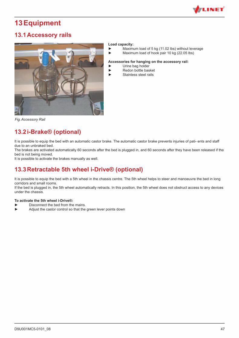
13 Equipment13.1 Accessory rails
Load capacity:► Maximum load of 5 kg (11.02 lbs) without leverage► Maximum load of hook pair 10 kg (22.05 lbs)
Accessories for hanging on the accessory rail:► Urine bag holder► Redon bottle basket► Stainless steel rails
Fig. Accessory Rail
13.2 i-Brake® (optional)It is possible to equip the bed with an automatic castor brake. The automatic castor brake prevents injuries of pati- ents and staff due to an unbraked bed.The brakes are activated automatically 60 seconds after the bed is plugged in, and 60 seconds after they have been released if the bed is not being moved.It is possible to activate the brakes manually as well.
13.3 Retractable 5th wheel i-Drive® (optional)It is possible to equip the bed with a 5th wheel in the chassis centre. The 5th wheel helps to steer and manoeuvre the bed in long corridors and small rooms.If the bed is plugged in, the 5th wheel automatically retracts. In this position, the 5th wheel does not obstruct access to any devices under the chassis.
To activate the 5th wheel i-Drive®:► Disconnect the bed from the mains.► Adjust the castor control so that the green lever points down
D9U001MC5-0101_0848
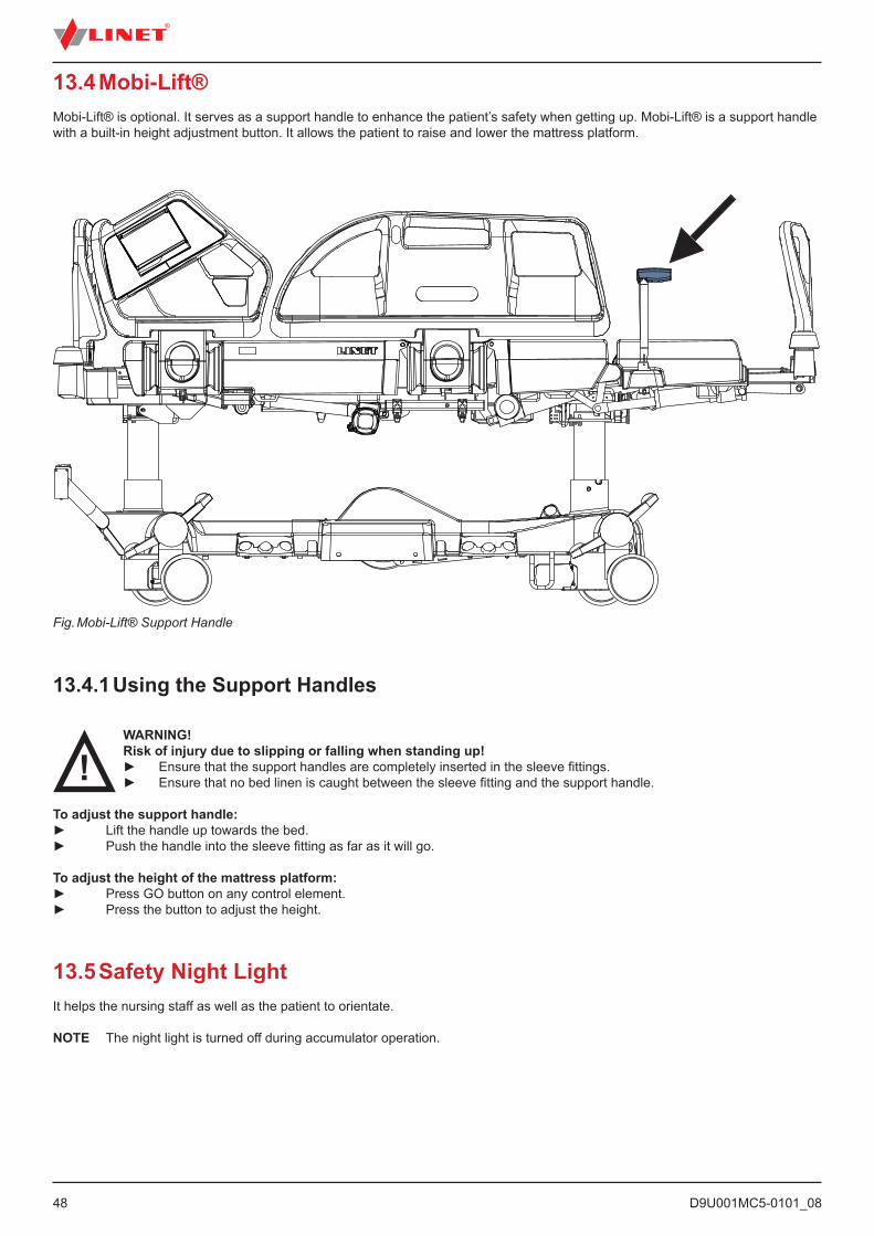
Fig. Mobi-Lift® Support Handle
13.4 Mobi-Lift®Mobi-Lift® is optional. It serves as a support handle to enhance the patient’s safety when getting up. Mobi-Lift® is a support handle with a built-in height adjustment button. It allows the patient to raise and lower the mattress platform.
13.4.1 Using the Support Handles
WARNING!Risk of injury due to slipping or falling when standing up!► Ensure that the support handles are completely inserted in the sleeve fittings.► Ensure that no bed linen is caught between the sleeve fitting and the support handle.
To adjust the support handle:► Lift the handle up towards the bed.► Push the handle into the sleeve fitting as far as it will go.
To adjust the height of the mattress platform:► Press GO button on any control element.► Press the button to adjust the height.
13.5 Safety Night LightIt helps the nursing staff as well as the patient to orientate.
NOTE The night light is turned off during accumulator operation.
D9U001MC5-0101_08
49
13.6 i-Drive Power (optional)
13.6.1 i-Drive Power System - Basic DescriptionIt is possible to equip the bed with the i-Drive Power wheel. The i-Drive Power helps hospital staff to drive the bed during patient transport with minimal manpower.The i-Drive wheel is located in the center of the bed under the undercarriage. i-Drive Power is equipped with its own accumulator and charger and it is not dependent on the bed functions so, if discharged you can still use the bed functions. The bed is equipped with one i-Drive controller. i-Drive is oriented in straight direction of the bed.
13.6.2 Safety instruction for i-Drive Power► Follow the instructions carefully.► Ensure that the bed is operated exclusively by qualified staff.► Make sure the siderails are pulled up during the transport.► Never use bed positioning buttons during transport.► Never use Fast forward button when descending. The Fast forward button is recommended for use when ascending as it is more efficient.► Special precaution need to be considered when reversing. Always keep distance from the bed and never use reverse button when descending or ascending.► Do not use Free Drive to transport on a slope greater than 1 degree unless adequate personnel are available to manage safe bed transport.► Never use the i-Drive Power to drive the bed up or down the slope that exceeds 6 degrees.► Never leave the bed with an activated i-Drive Power system without supervision of the trained staff.► Always use the regular mechanical brake system to brake and stabilize the bed.► Pay increased attention when driving the bed using i-Drive Power. Be aware of people and objects in close proximity and avoid collision with them by careful driving, especially by appropriate speed control.► Make sure the bed is unplugged and bed brakes are released before using i-Drive Power.► Push the emergency stop drive button if immediate movement interruption is needed (e.g. to avoid collision with other persons or objects).► Retract the i-Drive Power wheel to the undercarriage when parking. This will prevent misuse when unbraking and braking the bed.► The i-Drive Power electromagnetic brake is designed just for temporary bed stop and not for the permanent parking.► Switch off the i-Drive Power accumulator prior to long-term storage or transport.► Push the emergency retraction button under the chassis cover to retract the i-Drive Power wheel► in case an of i- Drive Power system failure. This will enable moving the bed to a safe area manually without using i-Drive Power.► Retract the i-Drive Power wheel to the undercarriage every time you intend to move the bed sideways.► Pay attention to the LED accumulator status indicator and plan your drive using the i-Drive Power accordingly. Insufficient accumulator capacity can cause unexpected complications and risks during the drive.► Always plug the bed in when you finish your drive in order to recharge the accumulator and keep your bed ready to go using the i-Drive Power.► The i-Drive Power accumulator must be replaced every 2 years to maintain proper functions of the i-Drive Power.
13.6.3 Specifications of UseWARNING!Risk of injury due to careless driving!► Always drive safely and carefully.► Observe the path for any obstacles and avoid collisions.► Ensure there are no people in your way.
► Manipulate with the bed carefully not to drive over any staff or patients.
CAUTION!Maximal clearance underneath the bed (with 15 cm castors) is 14 cm!► Observe the path for any obstacles and avoid collisions.
Intended use:► bed transport (with or without patient)
Unintended use:► riding the bed► other usage than described in instructions for use
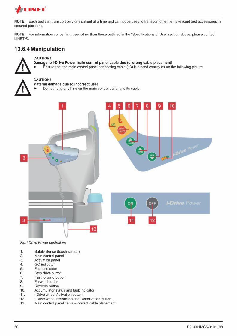
D9U001MC5-0101_0850
NOTE Each bed can transport only one patient at a time and cannot be used to transport other items (except bed accessories in secured position).
NOTE For information concerning uses other than those outlined in the “Specifications of Use” section above, please contact LINET ®.
13.6.4 ManipulationCAUTION!Damage to i-Drive Power main control panel cable due to wrong cable placement!► Ensure that the main control panel connecting cable (13) is placed exactly as on the following picture.
CAUTION!Material damage due to incorrect use!► Do not hang anything on the main control panel and its cable!
Fig. i-Drive Power controllers
1. Safety Sense (touch sensor)2. Main control panel3. Activation panel4. GO indicator5. Fault indicator6. Stop drive button7. Fast forward button8. Forward button9. Reverse button10. Accumulator status and fault indicator11. i-Drive wheel Activation button12. i-Drive wheel Retraction and Deactivation button13. Main control panel cable – correct cable placement
D9U001MC5-0101_08
51
NOTE The i-Drive Power controller cannot control the bed functions. Control the bed using the bed control elements.
NOTE The main control panel is enhanced with a touch sensor (1); your hand must always be in contact with the i-Drive Power control panel to use the functions. If released, the i-Drive Power will stop.NOTE Raising and lowering of the i-Drive wheel is electrically controlled by the i-Drive activation panel.
13.6.5 Powered DriveCAUTION!Damage to property due to incorrect transport and involuntary movement!► Prior to transport, ensure that the bed is disconnected from the mains.► Prior to transport, ensure that the auxiliary outlet plug (if available) is disconnected from the mains.► Ensure that the castors are locked prior to assembly, disassembly and maintenance (e.g.: i-Drive Power
maintenance). ► Ensure that the castors are locked when the bed is occupied. ► Hang the mains cable on the appropriate hook on the bed during transport.
1. Check, if the mains switch of i-Drive Power is activated.2. Press the ON (11) button on the Activation panel. The i-Drive wheel will lower and the GO indicator (4) will flash.3. Place your hand on the Safety Sense touch sensor (1) and push the buttons 7 or 8 for forward motion, or 9 for reverse motion. Your hand must be placed on the Safety Sense sensor to use the i- Drive Power, if released, the i-Drive Power will stop.4. The i-Drive motor is immediately stopped and the electric brake is activated after pressing the red stop drive button (6) when braking or in emergency.5. i-Drive Power control system is automatically deactivated and the electric brake is activated if no i-Drive function is used for 3 minutes. This is signalized by the green indicator (4) which is extinguished after 3 minutes.
NOTE Your hand must be placed on the Safety Sense panel to use the i-Drive Power.
NOTE i-Drive Power is not designed for ascending or descending a slope greater than 6° or longer than 65 ft. (20 m), especially when loaded. The support of personnel is needed when ascending or descending with a full SWL.
NOTE The i-Drive wheel has an electromagnetic brake for emergency or normal stopping of the bed. When parking it is always necessary, for safety reasons, to use the bed brakes (see chapter: Castor control and bed transport) which will brake all four bed castors.
NOTE When i-Drive wheel is lowered, it is not possible to move the bed to the sideways. Press the OFF button to retract the wheel, release the castors to the neutral position and then move the bed to any direction required.
13.6.6 Braking1. Press and hold the stop drive button (6) to brake immediately. -or-2. Press and hold the reverse button (9) to brake slowly (Press the Forward button to brake when reversing) -or-3. Release your hand f rom the touch sensor area (1) and i-Drive Power will brake automatically.
NOTE Always brake the bed when not transporting by using the castor control lever. The i-Drive brake is not designed to permanently brake the bed.
NOTE In a crisis situation (e.g. acceleration when driving down a steep slope) i-Drive dual braking prevents acceleration and slows down bed movement. However, it is not guaranteed the bed will stop by itself without personnel support (using stop drive button and castor control lever).
NOTE When descending, it is possible to actively brake using the opposite direction button to slow.
D9U001MC5-0101_0852
13.6.7 i-Drive Power Activation/Deactivation
Fig. i-Drive mains switch
To activate the i-Drive Power:1. Check, if the mains switch of i-Drive Power is activated (1).2. Press the Activation button ON located on the activation panel. The i-Drive wheel will lower and the green indicator will flash.
To deactivate the i-Drive Power:1. Retract the i-Drive wheel using the Retraction button located on the activation panel.2. Deactivate the i-Drive using the mains switch (1).
Emergency i-Drive Power wheel retraction:1. Press any GO button on the bed.2. Deactivate the i-Drive using the mains switch (1).3. Press the emergency retraction button (2).
NOTE Use emergency retraction in case of accumulator discharge or drive malfunction to move the bed to a safe area manually without using i-Drive Power.
13.6.8 Free DriveThe i-Drive motor is equipped with free drive, which is active after pressing the forwards (7 or 8) or backwards (9) buttons (until user holds the touch sensor area).Free Drive is deactivated and the brake is activated when the direction of motion is changed. This is feature for lowering the risks when going to a slope.
13.6.9 Accumulator
Accumulator charge status:1. While this indicator is flashing, the accumulator is critically dis-charged.2. 50%3. 75%4. 100% - the accumulator is charged
Fig. Accumulator indicator levels
To charge the accumulator:► Connect the bed main cable to mains power.► i-Drive will be charged (with the accumulator discharged, the charging may take up to 9 hours).
NOTE Accumulator charge values are just informational. Accumulator life is reduced when the accumulator is allowed to dis-charge completely.
D9U001MC5-0101_08
53
13.6.10 Fault SignalizationThe system is protected against failure states, by stopping and braking the drive system, and respective signalization. The fault indicator flashing briefly and the accumulator indicator shows the fault state. Some defects are cleared automatically (e.g.: drive overheating).
Error LED1 LED2 LED3 LED4Drive overheated* Off Off Off OnElectronics overheated* Off Off On OffBrake error Off Off On OnRetraction not completed Off On Off Off5V off limits Off On Off On
FETclosingpenetrated Off On On OffControl circuit overheated Off On On OnControlcircuiterror On Off Off OffActivation button stuck On Off Off OnRetraction button stuck On Off On OffActivebuttonafterstart On Off On On* An acoustic signal occurs before the drive is blocked (short acoustic signalization)NOTE LED indicators are numbered from the left.
13.6.11 Light Indicators
Indicator MeaningGo Indicator► Constantly lit► Flashing
Hand is on touch sensor; drive wheel is ready for use.Hand is not on touch sensor; i-Drive is not ready for use.
Fault Indicator► Constantly lit
► Flashing
i-Drive cannot be activated (i-Drive wheel is not lowered, castor control lever is braked, bed is connected to the mains).
System is faulty (indicated on accumulator status indicator, see service manual)-or-i-Drive control box heat protection is activated
13.6.12 Technical Specifications
Specification Valuei-Drive wheel diameter 8,27 in.Max. fast forward speed (flat ground, loaded) 4,43 Km/h (±15%)Max. forward speed (flat ground, loaded) 2,16 Km/h (±15%)Max. reverse speed (flat ground, loaded) 2,16 Km/h (±15%)Max. angle of ascent 6°Noise level (when retracting the drive wheel) 65 dB
13.6.13 Electrical specification
Specification ValueAccumulator Voltage 36 V DC, Capacity: 12 AhMaximum Power Input 300 WFuse Accumulator fuse pipe fuse T 3.15 A
MDP 030 (30 A)
D9U001MC5-0101_0854
13.6.14 I-Drive Power MaintenancePeriodical maintenance of the i-Drive Power must be done by qualified service technician or authorized service organization at least once a year.
Service technician must check the following:► accumulator status and eventual replacement of accumulator (after maximum of three years of duty)► gas spring – replace if necessary (after maximum of three years of duty)► i-Drive Power wheel – replace if necessary► lifting mechanism – grease if necessary► cables, control elements – replace if necessary► i-Drive Power function
NOTE To continue maintenance please see chapter Maintenance.
13.7 X-Ray Lung Examination
The backrest of the bed consists of HPL and is x-ray translucent. The bed is equipped with an x-ray cassette hol- der with 2 U-profiles under the backrest. This design allows taking x-ray images of the patient’s lungs without moving the patient manually.
13.7.1 Necessary Steps before the ExaminationNOTE This procedure is suitable for patients who cannot be moved due to critical conditions (e. g. internal bleeding).
► Make sure that patient is in centre of bed.► Make sure that backrest is in lowest position and siderails are folded up.► Pull out x-ray cassette holder.► Insert x-ray cassette (format 43×35 cm (16.93 in. x 13.78 in.)).► Push back x-ray cassette holder with x-ray cassette so that the cassette centre indicator is exactly under the edge of the mattress platform.► Correct position of x-ray cassette holder using the tooth mechanism so that the upper edge of the x-ray cassette is exactly under the patient’s shoulder line.► Adjust parameters of the x-ray device.
13.7.2 Examination with C-armBackrest and seat of the bed are x-ray translucent. The bed is equipped with a column construction. This design allows C-arm--assisted operations (mainly cardiological operations such as temporary external cardiostimulation) without moving the patient. The x-ray tube of the C-arm is located between the undercarriage and the mattress platform.
Necessary Steps before the Operation
► Make sure that backrest is in highest position and siderails are folded up.► Position upper part of C-arm (sensor and indicator) above the patient’s chest.
Fig. X-Ray Lung Examination
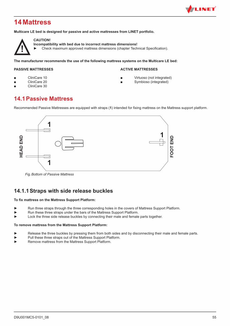
D9U001MC5-0101_08
55
14 MattressMulticare LE bed is designed for passive and active mattresses from LINET portfolio.
CAUTION!Incompatibility with bed due to incorrect mattress dimensions!► Check maximum approved mattress dimensions (chapter Technical Specification).
The manufacturer recommends the use of the following mattress systems on the Multicare LE bed:
PASSIVE MATTRESSES
■ CliniCare 10 ■ CliniCare 20■ CliniCare 30
ACTIVE MATTRESSES
■ Virtuoso (not integrated)■ Symbioso (integrated)
14.1 Passive MattressRecommended Passive Mattresses are equipped with straps (1) intended for fixing mattress on the Mattress support platform.
Fig. Bottom of Passive Mattress
11
HEA
D E
ND
FOO
T EN
D
1
14.1.1 Straps with side release bucklesTo fix mattress on the Mattress Support Platform:
► Run three straps through the three corresponding holes in the covers of Mattress Support Platform.► Run these three straps under the bars of the Mattress Support Platform.► Lock the three side release buckles by connecting their male and female parts together.
To remove mattress from the Mattress Support Platform:
► Release the three buckles by pressing them from both sides and by disconnecting their male and female parts.► Pull these three straps out of the Mattress Support Platform.► Remove mattress from the Mattress Support Platform.
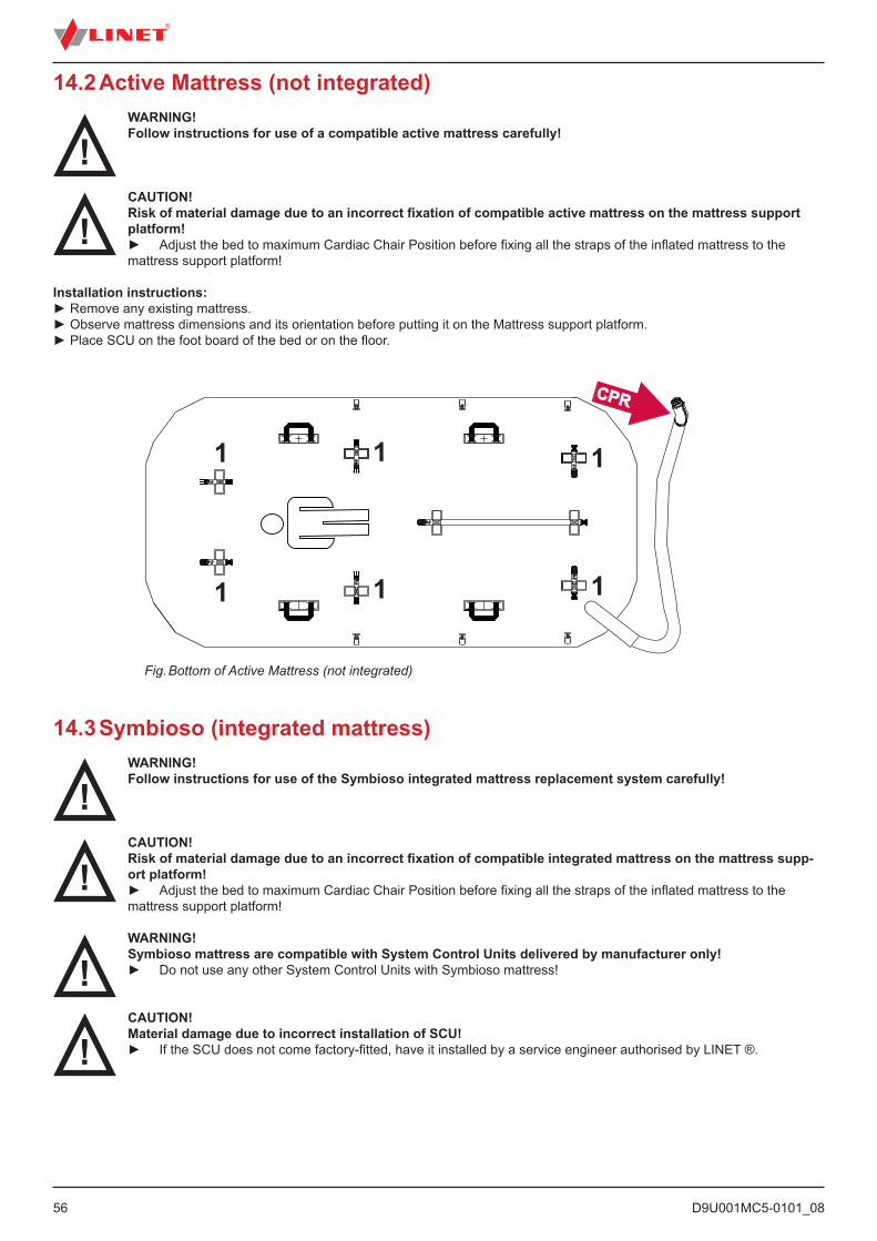
D9U001MC5-0101_0856
14.3 Symbioso (integrated mattress)WARNING!Follow instructions for use of the Symbioso integrated mattress replacement system carefully!
CAUTION!Risk of material damage due to an incorrect fixation of compatible integrated mattress on the mattress supp-ort platform!► Adjust the bed to maximum Cardiac Chair Position before fixing all the straps of the inflated mattress to the mattress support platform!
WARNING!Symbioso mattress are compatible with System Control Units delivered by manufacturer only!► Do not use any other System Control Units with Symbioso mattress!
CAUTION!Material damage due to incorrect installation of SCU!► If the SCU does not come factory-fitted, have it installed by a service engineer authorised by LINET ®.
Fig. Bottom of Active Mattress (not integrated)
1
1
1
1
1
1
14.2 Active Mattress (not integrated)WARNING!Follow instructions for use of a compatible active mattress carefully!
CAUTION!Risk of material damage due to an incorrect fixation of compatible active mattress on the mattress support platform!► Adjust the bed to maximum Cardiac Chair Position before fixing all the straps of the inflated mattress to the mattress support platform!
Installation instructions:► Remove any existing mattress.► Observe mattress dimensions and its orientation before putting it on the Mattress support platform.► Place SCU on the foot board of the bed or on the floor.
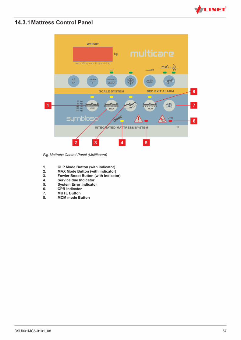
D9U001MC5-0101_08
57
Fig. Mattress Control Panel (Multiboard)
14.3.1 Mattress Control Panel
1. CLP Mode Button (with indicator)2. MAX Mode Button (with indicator) 3. Fowler Boost Button (with indicator)4. Service due Indicator5. System Error Indicator6. CPR indicator7. MUTE Button8. MCM mode Button
D9U001MC5-0101_0858
15 AccessoriesWARNING!Risk of injury due to incompatible accessories!► Use exclusively original accessories from the manufacturer.The manufacturer is not responsible for the use of unapproved accessories.
WARNING!Risk of injury due to damaged accessories!► Use exclusively accessories in perfect condition.
15.1 Lifting PoleTo ensure safe use of the lifting pole:► Never exceed the maximum load of 75 kg (165.35 lbs).► Never use the lifting pole for rehabilitation exercises.► To prevent the bed from tipping over, ensure that the lifting pole does not project out from the bed.► Replace plastic handle every 4 years.
To install the lifting pole:► Insert lifting pole in corresponding sleeve fitting on lifting pole adapter at head end.► Ensure that safety pin locks into place.
A plastic grab handle with an adjustable strap shall be attached to the lifting pole.
NOTE The lifting pole adapter is optional. It is necessary to specify this feature in the order.
NOTE The date of manufacture is marked on the grab handle. LINET® recommends replacing the plastic grab handle every four years.
D9U001MC5-0101_08
59
15.2 Infusion StandsWARNING!Risk of injury due to use of incorrect accessories or because of incorrect use!Infusion Stands must only be used for their intended use. Always read the instructions for use!► Only mount an infusion pump to the lower (wider) telescopic section of an infusion stand above the head board/
foot board. ► Never mount an infusion pump to the upper (thiner) telescopic section of an infusion stand. ► Ensure the infusion pump will not collide with any movable parts of the bed (especially backrest part) or with the patient. This must be verified during installation. ► Do not over tighten the infusion pump clamps during fitment. Over tightening may damage the infusion stand. ► Infusion pump can be only used if the infusion stand is fitted in the accessory holder socket in the head end on the undercarriage of the bed. ► Do not use the infusion stand as driving/pushing device during the bed transport.
Infusion stands can be fitted to the head and foot board by either fitting into the IV/Infusion sockets mounted on the bed or using alternative accesory holder socket in the head end on the undercarriage of the bed.
Fig. Infusion Stand Fig. Infusion Pump – Correct Fitment
► Use exclusively infusion stands with 4 hooks for hanging IV bags or baskets for intravenous solutions.► Ensure the infusion stand individual hook 2kg maxi-mum Safe Working Load is not exceeded.► Ensure the infusion stand 20kg maximum Safe Working Load is not exceeded.► The total maximum loading of the IV/Infusion poles must not exceed 20 Kg (44.1lbs).
15.3 Stabilising PadsThe stabilising pads ensure a stable position of the patient during lateral tilt in order to prevent extubation or disconnection of IV lines or other equip-ment.
Stabilising pad set:► 2 lateral arm pads► 2 lateral leg pads► 2 head pads► 1 internal leg pad
Applying pads:► Position the patient in the middle of the bed.► Place lateral pads between patient and siderails.► Attach head pads to arm pads with Velcro.► Place internal pad between the patient’s legs.► Tilt mattress platform left and right by 30° to check if the patient’s position is stable.► The position is stable if the patient does neither shift nor turn over.
Fig. Stabilising Pads
D9U001MC5-0101_0860
15.4 Ventilation Circuit HolderThe ventilation circuit holder prevents an extubation.► Always use a LINET® ventilation circuit holder to prevent extubation when the bed is tilted laterally.
Applying ventilation circuit holder:► Put ventilation circuit holder in hole on right or left of head end.► Fasten ventilation circuit holder with wing screw provided.► Put intubation tube through plastic head of ventilation circuit holder.► Tilt mattress platform left and right by 30° to check if intubation tube is fastened securely. The fastening is secure if no parts of the ventilation circuit are disconnected.
Fig. Ventilation Circuit Holder
15.5 Monitor TrayThe monitor tray is suitable for transporting monitors with a weight of up to 15 kg (33.07 lbs).
Installing the monitor tray:► Insert two vertical monitor tray tubes into corner sleeves on foot end.► Fixate monitor with safety belts in order to avoid any damage during transport.
Fig. Monitor Tray
D9U001MC5-0101_08
61
15.6 Oxygen Bottle HoldersWARNING!Risk of injury with oxygen bottle holder due to incorrect use or due to careless driving!► Ensure the oxygen bottle holder is correctly fi tted in correct position.► It is necessary to place oxygen bottle holder (with or without O2 bottle) before transport to secure transport position.
► Be aware of people or objects in close proximity when driving or manipulating the bed equipped with oxygen bottle holder. ► Secure the oxygen bottles against falling or involuntary movement with rubber strap. ► Place the oxygen bottle holder on the bed by instructions in the following text. ► Ensure the oxygen bottle valve will not get damaged by careless or incorrect manipulation or placement.
The oxygen bottle holders are suitable for transporting oxygen bottles with a weight of up to 15 kg (33.07 lbs) and a volume of 5 litres.
Version A► Put oxygen bottle holder on transversal profi le behind head end.
NOTE Using oxygen bottle holder 4MAR2010PC004 is not possible if the bed is equipped with an additional adapter for a lifting pole.
Version B► Put holder on sleeve fi ttings in multifunctional accessory adapter on chassis.► Ensure the locking pin of oxygen bottle holder B is locked in sleeve fi tting.
Fig. Oxygen Bottle Holder B – correct fi tment
Fig. Oxygen Bottle Holder B – incorrect fi tment
Version C► Put oxygen bottle holder on all 4 accessory adapters on chassis.
Fig. Oxygen Bottle Holder C
Fig. Oxygen Bottle Holder A
D9U001MC5-0101_0862
15.7 ProtectorWARNING!Risk of injury due to the patient falling off the bed!► Ensure that the Protector is installed securely.► Always check that the siderails are properly locked.
The Protector is an optional accessory for the Multicare LE bed. The main purpose of the Protector is to reduce the risk of patients falling off the bed.
Fig. Multicare LE bed with Protector
1. Inserting the Protector into the casing in the protective ring on the corner2. The Protector inserted in the casing3. The fixing element attached to the telescopic profile of the bed extension4. The Protector attached to the Multicare LE bed (The Protector can also be used on expanded beds.)
Attach the Protector to the bed as follows:► Insert the Protector pin into the casing in the protective ring at the corner of the foot end of the bed (1).► Ensure that the fixing element is secured to the telescopic profile of the bed extension (3).
Remove the Protector from the bed as follows:► Grasp the upper end of the Protector.► Remove the Protector from the casing.
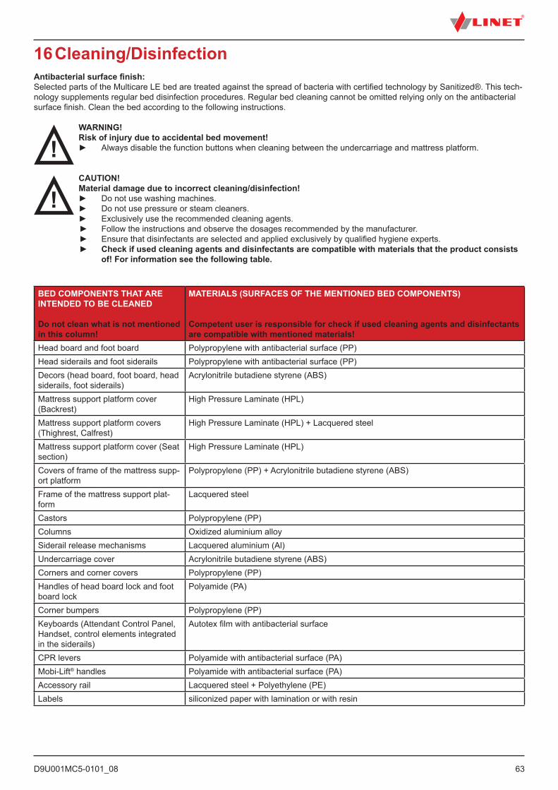
D9U001MC5-0101_08
63
16 Cleaning/DisinfectionAntibacterial surface finish: Selected parts of the Multicare LE bed are treated against the spread of bacteria with certified technology by Sanitized®. This tech-nology supplements regular bed disinfection procedures. Regular bed cleaning cannot be omitted relying only on the antibacterial surface finish. Clean the bed according to the following instructions.
WARNING!Risk of injury due to accidental bed movement!► Always disable the function buttons when cleaning between the undercarriage and mattress platform.
CAUTION!Material damage due to incorrect cleaning/disinfection!► Do not use washing machines.► Do not use pressure or steam cleaners.► Exclusively use the recommended cleaning agents.
► Follow the instructions and observe the dosages recommended by the manufacturer. ► Ensure that disinfectants are selected and applied exclusively by qualified hygiene experts. ► Check if used cleaning agents and disinfectants are compatible with materials that the product consists of! For information see the following table.
BED COMPONENTS THAT ARE INTENDED TO BE CLEANED
Do not clean what is not mentioned in this column!
MATERIALS (SURFACES OF THE MENTIONED BED COMPONENTS)
Competent user is responsible for check if used cleaning agents and disinfectants are compatible with mentioned materials!
Head board and foot board Polypropylene with antibacterial surface (PP)Head siderails and foot siderails Polypropylene with antibacterial surface (PP)Decors (head board, foot board, head siderails, foot siderails)
Acrylonitrile butadiene styrene (ABS)
Mattress support platform cover (Backrest)
High Pressure Laminate (HPL)
Mattress support platform covers (Thighrest, Calfrest)
High Pressure Laminate (HPL) + Lacquered steel
Mattress support platform cover (Seat section)
High Pressure Laminate (HPL)
Covers of frame of the mattress supp-ort platform
Polypropylene (PP) + Acrylonitrile butadiene styrene (ABS)
Frame of the mattress support plat-form
Lacquered steel
Castors Polypropylene (PP)Columns Oxidized aluminium alloySiderail release mechanisms Lacquered aluminium (Al)Undercarriage cover Acrylonitrile butadiene styrene (ABS)Corners and corner covers Polypropylene (PP)Handles of head board lock and foot board lock
Polyamide (PA)
Corner bumpers Polypropylene (PP)Keyboards (Attendant Control Panel, Handset, control elements integrated in the siderails)
Autotex film with antibacterial surface
CPR levers Polyamide with antibacterial surface (PA)Mobi-Lift® handles Polyamide with antibacterial surface (PA)Accessory rail Lacquered steel + Polyethylene (PE)Labels siliconized paper with lamination or with resin
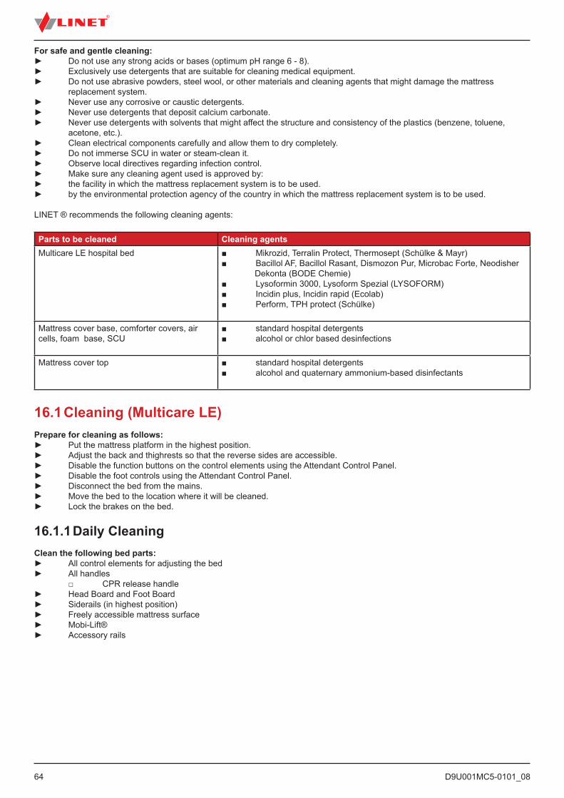
D9U001MC5-0101_0864
16.1 Cleaning (Multicare LE)Prepare for cleaning as follows:► Put the mattress platform in the highest position.► Adjust the back and thighrests so that the reverse sides are accessible.► Disable the function buttons on the control elements using the Attendant Control Panel.► Disable the foot controls using the Attendant Control Panel.► Disconnect the bed from the mains.► Move the bed to the location where it will be cleaned.► Lock the brakes on the bed.
16.1.1 Daily CleaningClean the following bed parts:► All control elements for adjusting the bed► All handles □ CPR release handle► Head Board and Foot Board► Siderails (in highest position)► Freely accessible mattress surface► Mobi-Lift®► Accessory rails
For safe and gentle cleaning:► Do not use any strong acids or bases (optimum pH range 6 - 8).► Exclusively use detergents that are suitable for cleaning medical equipment.► Do not use abrasive powders, steel wool, or other materials and cleaning agents that might damage the mattress replacement system.► Never use any corrosive or caustic detergents.► Never use detergents that deposit calcium carbonate.► Never use detergents with solvents that might affect the structure and consistency of the plastics (benzene, toluene, acetone, etc.).► Clean electrical components carefully and allow them to dry completely.► Do not immerse SCU in water or steam-clean it.► Observe local directives regarding infection control.► Make sure any cleaning agent used is approved by:► the facility in which the mattress replacement system is to be used.► by the environmental protection agency of the country in which the mattress replacement system is to be used.
LINET ® recommends the following cleaning agents:
Parts to be cleaned Cleaning agentsMulticare LE hospital bed ■ Mikrozid, Terralin Protect, Thermosept (Schülke & Mayr)
■ Bacillol AF, Bacillol Rasant, Dismozon Pur, Microbac Forte, Neodisher Dekonta (BODE Chemie)■ Lysoformin 3000, Lysoform Spezial (LYSOFORM)■ Incidin plus, Incidin rapid (Ecolab)■ Perform, TPH protect (Schülke)
Mattress cover base, comforter covers, air cells, foam base, SCU
■ standard hospital detergents■ alcohol or chlor based desinfections
Mattress cover top ■ standard hospital detergents■ alcohol and quaternary ammonium-based disinfectants
D9U001MC5-0101_08
65
16.1.2 Cleaning before Changing PatientsClean the following bed parts:► All control elements for adjusting the bed► All handles □ CPR release handle► Head Board and Foot Board► Siderails (in highest position)► Freely accessible mattress surface► Mobi-Lift®► Accessory rails► All plastic mattress platform covers► Plastic undercarriage covers► Telescopic columns► Mattress on all sides► Freely accessible metal parts of mattress platform► Cable ducts► Lifting pole sleeve fitting► Infusion stand sleeve fitting► Bumpers► Castors► Brakes
16.1.3 Complete Cleaning and DisinfectionClean the following bed parts:► All control elements for adjusting the bed► All handles □ CPR release handle► Head Board and Foot Board► Siderails (in highest position)► Freely accessible mattress surface► Mobi-Lift®► Accessory rails► All plastic mattress platform covers► Plastic undercarriage covers► Telescopic columns► Mattress on all sides► Freely accessible metal parts of mattress platform► Cable ducts► Lifting pole sleeve fitting► Infusion stand sleeve fitting► Bumpers► Castors► Brakes► Interior parts► (accessible after removing mattress platform covers)
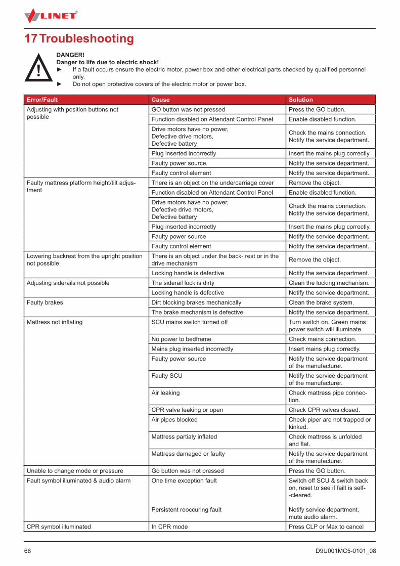
D9U001MC5-0101_0866
Error/Fault Cause SolutionAdjusting with position buttons not possible
GO button was not pressed Press the GO button.Function disabled on Attendant Control Panel Enable disabled function.Drive motors have no power, Defective drive motors,Defective battery
Check the mains connection. Notify the service department.
Plug inserted incorrectly Insert the mains plug correctly.Faulty power source. Notify the service department.Faulty control element Notify the service department.
Faulty mattress platform height/tilt adjus-tment
There is an object on the undercarriage cover Remove the object.Function disabled on Attendant Control Panel Enable disabled function.Drive motors have no power, Defective drive motors,Defective battery
Check the mains connection. Notify the service department.
Plug inserted incorrectly Insert the mains plug correctly.Faulty power source Notify the service department.Faulty control element Notify the service department.
Lowering backrest from the upright position not possible
There is an object under the back- rest or in the drive mechanism Remove the object.
Locking handle is defective Notify the service department.Adjusting siderails not possible The siderail lock is dirty Clean the locking mechanism.
Locking handle is defective Notify the service department.Faulty brakes Dirt blocking brakes mechanically Clean the brake system.
The brake mechanism is defective Notify the service department.Mattress not inflating SCU mains switch turned off Turn switch on. Green mains
power switch will illuminate.No power to bedframe Check mains connection. Mains plug inserted incorrectly Insert mains plug correctly. Faulty power source Notify the service department
of the manufacturer. Faulty SCU Notify the service department
of the manufacturer. Air leaking Check mattress pipe connec-
tion. CPR valve leaking or open Check CPR valves closed.Air pipes blocked Check piper are not trapped or
kinked.Mattress partialy inflated Check mattress is unfolded
and flat. Mattress damaged or faulty Notify the service department
of the manufacturer. Unable to change mode or pressure Go button was not pressed Press the GO button.Fault symbol illuminated & audio alarm One time exception fault
Persistent reoccuring fault
Switch off SCU & switch back on, reset to see if failt is self--cleared.
Notify service department, mute audio alarm.
CPR symbol illuminated In CPR mode Press CLP or Max to cancel
17 TroubleshootingDANGER!Danger to life due to electric shock!► If a fault occurs ensure the electric motor, power box and other electrical parts checked by qualified personnel
only. ► Do not open protective covers of the electric motor or power box.
D9U001MC5-0101_08
67
18 MaintenanceWARNING!Risk of injury when working on the bed!► Ensure that the bed is disconnected from the mains power prior to installation, putting into service, maintenance
and deinstallation.► Ensure that the castors are locked prior to installation, putting into service, maintenance and deinstallation.
WARNING!Risk of injury due to defective bed!► Have a defective bed repaired immediately.► If the defect cannot be repaired, do not use the bed.
CAUTION!Material damage due to incorrect maintenance!► Ensure that maintenance is performed exclusively by manufacturer´s customer service or by authorised service
personnel certified by the manufacturer.► If the defect cannot be repaired, do not use the bed.
LINET ® recommends attaching the maintenance plaque to the bed.
18.1 Regular maintenance► Check regularly movable parts for wear.► Perform regularly visual check of the product (with delivery note if necessary).► Ask service department of the manufacturer for addition of the original spare parts if some product parts are missing.► Ask service department of the manufacturer for replacement of any damaged product parts by the original spare parts.► Check that the accumulator is working properly. Disconnect the bed from the mains power to check signalisation of accumulator indicator according to the instructions for use.► Have the accumulator replaced if it is not working properly.► Check regularly that all accessories are working properly.► Replace damaged accessories immediately.
18.2 Spare PartsThe serial label is located on the frame of the mattress support platform. The serial label contains information for claims and orde-ring replacement parts.
Information about spare parts is available from:■ Manufacturer´s customer service■ Sales department
18.3 Safety Technical ChecksWARNING!Risk of injury due to incorrect safety technical checks!► Ensure that safety technical checks are performed exclusively by manufacturer´s customer service or by authori-sed service personnel certified by the manufacturer.► Ensure that the safety technical checks are recorded in the service and maintenance log.
Safety technical check of the medical bed must be performed at least once every 12 months.
The procedure for performing the safety technical check is stipulated in EN 62353:2014.
NOTE On request, the manufacturer will provide service documentation (e.g. circuit diagrams, component part lists, descriptions, calibration instructions etc.) for service personnel for the repair of ME equipment designated by the manufacturer as repairable by service personnel.
D9U001MC5-0101_0868
19 Disposal19.1 Environment ProtectionThe company LINET® is aware of the importance of environmental protection for future generations. Within this company the environmental management system is applied in accordance with the internationally agreed standard ISO 14001. The compliance with this standard is annually tested by the external audit executed by an authorised company. Based on the Directive No. 2002/96/EC (Directive WEEE - Waste, Electric and Electronic Equipments) the company LINET, s. r. o. is registered in the List of Electric and Electronic Equipment Producers (Seznam výrobců elektrozařízení) on the Ministry of the Environment of the Czech Republic (Ministerstvo životního prostředí).
Materials used in this product are not environmentally hazardous. LINET® products meet valid requirements of national and Euro-pean legislation in the areas of RoHS and REACH, so they do not contain any prohibited substances in excess quantities. None of the wooden parts is made of tropical wood (such as mahogany, rosewood, ebony, teak etc.) or made of timber from the Amazon region or from similar rainforests. Product noise (sound pressure level) meets requirements of the regulations for the pro-tection of public health against undesirable effects of noise and vibration in protected interior spaces of buildings (according to stan-dard IEC 60601-2-52). Used packaging materials are in accordance with requirements of the Packaging Act (Zákon o obalech). For disposal of packaging materials after installation of products contact your sales representative or manufacturer´s customer service about the possibility of a free take-back of packaging through an authorized company (more details on www.LINET.cz).
19.2 DisposalThe main objective of the obligations arising from the European Directive No. 2012/19/EU on Waste, Electric and Electronic Equip-ments (nationally regulated in Act No. 185/2001 Coll. as amended. On Waste and in Decree of the Ministry of the Environment No. 352/2005 Coll. as amended), is to increase the re-use, material recovery and recovery of electric and electronic equipment at the required level, thereby avoiding the production of waste and thereby avoiding the possible harmful effects of hazardous substances contained in electric and electronic equipment on human health and the environment. LINET® electric and electronic equipments that have a built-in accumulator or accumulator are designed so that the used accumulator or accumulators can be safely removed by LINET® qualified service technicians. There is an information about its type on the built-in accumulator or accumulator.
19.2.1 Within EuropeTo dispose of the electric and electronic equipment:
► The electric and electronic equipment must not be disposed of as household waste.► Dispose of this equipment at designated collection points or take-back points.
To dispose of the other equipment:
► The equipment must not be disposed of as household waste.► Dispose of this equipment at designated collection points or take-back points.
LINET® participates in a collective system with take-back company REMA System (see www.remasystem.cz/sberna-mista/). By bringing electric and electronic equipment to a take-back point, you participate in recycling and you save primary raw material resources while protecting your environment from effects of unprofessional disposal.
19.2.2 Outside Europe► Dispose of the product or its components in accordance with local laws and regulations!► Hire an approved waste disposal company for disposal!
D9U001MC5-0101_08
69
20 WarrantyLINET ® will only be held responsible for the safety and reliability of products that are regularly serviced, maintained and used in accordance with the safety guidelines.
Should a serious defect arise that cannot be repaired during maintenance:► Do not continue to use the bed.
This product is covered by a 24-month warranty from the date of purchase. The warranty covers all material and manufacturing-re-lated failures and errors. Failures and errors caused by incorrect use and external effects are not covered. Justified complaints will be fixed free of charge during the warranty period. Proof of purchase, with the date of purchase, is required for all warranty service. Our standard terms and conditions apply.
21 Standards and RegulationsApllied norms are stated on Declaration of Conformity.
The manufacturer adheres to a certified quality management system in compliance with the following standards:
■ ISO 9001■ ISO 14001■ ISO 13485■ MDSAP (Medical Device Single Audit Program)