Embed Size (px)
Citation preview

Precision since 1968
INSTRUCTIONS FOR USE
DURAPLANT
Surgery II implant recovery standard technique
Surgery II implant recovery rolled flap technique
Temporary treatment following implant recovery
Crowns and bridges on Tiversa rigid straight
Crowns and bridges on Tiversa customisable
Full denture on Tiversa ball
Full denture on Steco magnets
Full denture on bar attachment
Recall
ZL Duraplant implant system instructions for use
Temporary treatment following implant placement
Surgery 1 using a bone spider
CONTENTS
Surgical planning for a partially edentulous jaw
Surgical planning for an edentulous jaw
Surgery 1 without bone repositioning
Principles
Copyright © 2007 byZL-MICRODENT-ATTACHMENT GMBH & CO.KGD-58335 Breckerfeld
Printed in GermanyISBN 3-00-011443-2 All rights reserved. No part of this publication may be reproduced, stored in a retrieval system or transmitted in any form or by any means, electronic, mechanical, photocopying, recording or translated into another language.
32
Page 3
Page 8
Page 6
Page 4
Page 12
Page 14
Page 15
Page 17
Page 19
Page 20
Page 27
Page 30
Page 34
Page 36
Page 46
Page 47
Clinical photographsProf. Dr. Hans-Ludwig Graf,Annett SparfeldDepartment of Oral and Maxillofacial Surgery, University of Leipzig, Germany
Technical photographsWillibert MöllerfeldZL-Microdent
PRINCIPLESDURAPLANT
Note:Our medical and technical safety advisors constantly check information on our products and their application.The user should, however, check our product information and recommen-dations to ensure that the product is suitable for the intended use. If we make any modifications to products or their application in the course of technical or medical development, we reserve the right to supply the modified product. We offer expert advice as a free customer service without liability. Claims for compensation are restricted to claims made under guarantee and to our general terms of sale and delivery as stipulated in the contract.
PRINCIPLESDental implant treatment is a modern form of dentistry based on biomaterial research. It encompasses all sub-disciplines in dentistry and incorporates their basic principles.
Though implant treatment is always indicated from the prosthetic point of view, the other branches of dentistry, general medicine and psychiatry may present contraindications.
A compromise always has to be made between the prosthetic ideal, technical limitations and practical options for oral surgery when planning the implant sites as well as when actually placing the implants during surgery. Normally this compromise has to be made intraoperatively. The long-term success of any implant is based on accurately establishing the indication, selecting a suitable implant system for the planned treatment, precise preimplant planning and oral surgery, integrating the prosthetic superstructure in the overall concept for rehabilitating the orofacial system and strict adherence to recall appointments for periodontal examination.
GENERAL PRINCIPLES FOR IMPLANT INDICATION
The long-term function of any type of implant basically depends on a stable balance between the effects of the implant on the organism and the potential of that organism to compensate for these effects.Any therapeutic effect is always accompanied by side effects. Anyone involved in developing implants, as well as any dentist placing implants, is confronted by this fundamental problem.
The aim of our research was to increase the therapeutic scope and effectiveness of the system while reducing side effects to a minimum. Even with an optimised implant system, the procedure used must still follow the principles of dental implantology.Basically it should be taken into consideration thatan implant is a synthetic product and an implant-borne restorationrequires surgery.
Being a synthetic product, an implant is not an active component in an evolved feedback control system. Consequently, it is in a much more unstable state of equilibrium than a tooth. When planning an implant-borne restoration, the dentist must include adequate safety precautions and therefore has to monitor an implant much more closely than a tooth. Otherwise, even minor noxae could affect the unstable equilibrium of the implant. An indication for implant treatment should be carefully considered and strictly defined.
SYSTEM PARAMETERS
1.Vertical space required for crowns:> 5.50 mm
2. Vertical space required bar restorations:> 7.00 mm
3.Max. angle between the implant axis and su-perstructure axis:- 20°- + 20°
4. Implant lengths: 9 mm12 mm15 mm(special lengths on request; maintain a safe gap)
5. Implant diameters: Ø 2.90 mm Ø 3.20 mm Ø 3.50 mm Ø 3.80 mm Ø 4.10 mm(maintain bone wall thickness)
6. Distance between implants with partial den-tures(splinted crowns)(special abutment for lower anteriors)> 4.2 mm
7. Distance between implants with bar resto-rations> 9 mm< 20 mm
CONTRAINDICATIONSIf it is known beforehand that the patient has a general or specific medical condition or even psychosocial problems that would have a nega-tive effect, i.e. compensation mechanisms are clearly limited or noxae will be excessive, implant treatment cannot be carried out without accepting considerable risks. Based on these principles, there are a number of conditions or illnesses that contraindicate implantation.
Implantation is contraindicated in the following instances:
1. Surgery involves too many risks.
2. The patient has a condition or illness that does not guarantee normal wound healing.
3. The patient has a condition or illness that affects normal functioning of the immune system.
4. The patient has a condition or illness that pre-cludes normal bone reactivity.
5. The patient has a condition or illness that nega-tively affects the relation between the load transfer-ring implant surface and applied stresses.
6. The patient has a condition or illness that increases bacterial or mechanical loading of the abutment emergence profile beyond its potential for compensation.
7. The patient has a condition or illness that makes the patient unwilling or unable to recognise the advantages and special hygiene requirements of an implant-borne restoration.
More detailed information is included in the text.
We reserve the right to make technical changes. No part of this publication may be reproduced without the prior permission of the publisher in writing.
Copyright © 2007 byZL-MICRODENT-ATTACHMENT GMBH & CO. KGD-58335 Breckerfeld
Registered Trade Marks of ZL Microdent:Bone-spider®,Bone-up®, DURAPLANT®,DUROBOND®, MICRODENT® ,Tectu-Sil®,TICER®, TILABOR®, TIMEDUR®,TIVERSA®,Unor®, ZL MICRODENT®.
32
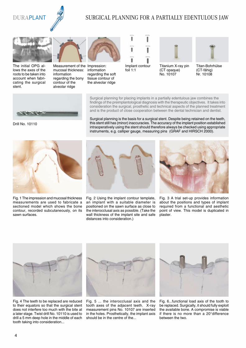
The initial OPG al-lows the axes of the roots to be taken into account when fabri-cating the surgical stent.
Fig. 4 The teeth to be replaced are reduced to their equators so that the surgical stent does not interfere too much with the bite at a later stage. Twist drill No. 10110 is used to drill a 5 mm deep hole in the middle of each tooth taking into consideration...
Surgical planning for placing implants in a partially edentulous jaw combines the findings of the preimplantological diagnosis with the therapeutic objectives. It takes into consideration the surgical, prosthetic and technical aspects of the planned treatment and is the product of close cooperation between the dental technician and dentist.
Surgical planning is the basis for a surgical stent. Despite being retained on the teeth, this stent still has (minor) inaccuracies. The accuracy of the implant position established intraoperatively using the stent should therefore always be checked using appropriate instruments, e.g. calliper gauge, measuring pins (GRAF and HIRSCH 2000).
Drill No. 10110
Fig. 1 The impression and mucosal thickness measurements are used to fabricate a sectioned model which shows the bone contour, recorded subcutaneously, on its sawn surfaces.
Fig. 3 A trial set-up provides informationabout the positions and types of implant required from a functional and aestheticpoint of view. This model is duplicated in plaster.
Fig. 5 ... the interocclusal axis and the tooth axes of the adjacent teeth. X-ray measurement pins No. 10107 are inserted in the holes. Prosthetically, the implant axis should be in the centre of the...
Fig. 6...functional load axis of the tooth to be replaced. Surgically, it should fully exploit the available bone. A compromise is viable if there is no more than a 20°difference between the two.
Fig. 2 Using the implant contour template, an implant with a suitable diameter is positioned on the sawn surface as close to the interocclusal axis as possible. (Take the wall thickness of the implant site and safe distances into consideration.)
Measurement of the mucosal thickness: information regarding the bonycontour of thealveolar ridge
Impression: information regarding the soft tissue contour of the alveolar ridge
Implant contourfoil 1:1
Titanium X-ray pin (CT opaque)No. 10107
Titan-Bohrhülse(CT-fähig)Nr. 10108
SURGICAL PLANNING FOR A PARTIALLY EDENTULOUS JAWDURAPLANT
54
SURGICAL PLANNING FOR A PARTIALLY EDENTULOUS JAW
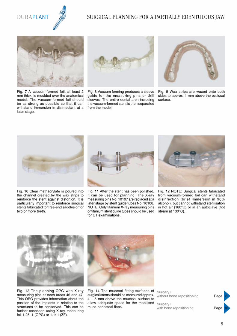
Fig. 7 A vacuum-formed foil, at least 2 mm thick, is moulded over the anatomical model. The vacuum-formed foil should be as strong as possible so that it can withstand immersion in disinfectant at a later stage.
Fig. 8 Vacuum forming produces a sleeve guide for the measuring pins or drill sleeves. The entire dental arch including the vacuum-formed stent is then separated from the model.
Fig. 9 Wax strips are waxed onto both sides to approx. 1 mm above the occlusal surface.
Fig. 10 Clear methacrylate is poured into the channel created by the wax strips to reinforce the stent against distortion. It is particularly important to reinforce surgical stents fabricated for free-end saddles or for two or more teeth.
Fig. 11 After the stent has been polished, it can be used for planning. The X-ray measuring pins No. 10107 are replaced at a later stage by stent guide tubes No. 10108. NOTE: Only titanium X-ray measuring pins or titanium stent guide tubes should be used for CT examinations.
Fig. 14 The mucosal fitting surfaces of surgical stents should be contoured approx. 4 – 5 mm above the mucosal surface to allow adequate space for the mobilised muco-periosteal flaps.
Fig. 13 The planning OPG with X-ray measuring pins at tooth areas 46 and 47. This OPG provides information about the position of the implants in relation to the structures to be conserved. This can be further assessed using X-ray measuring foil 1.25: 1 (OPG) or 1.1: 1 (ZF).
Fig. 12 NOTE: Surgical stents fabricated from vacuum-formed foil can withstand disinfection (brief immersion in 90% alcohol), but cannot withstand sterilisation in hot air (180°C) or in an autoclave (hot steam at 130°C).
Surgery Iwithout bone repositioning Page 8
Surgery Iwith bone repositioning Page 12
DURAPLANT
54
SURGICAL PLANNING FOR AN EDENTULOUS JAW
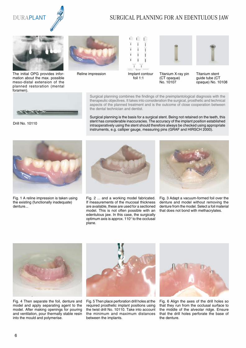
The initial OPG provides infor-mation about the max. possible meso-distal extension of the planned restoration (mental foramen).
Fig. 4 Then separate the foil, denture and model and apply separating agent to the model. After making openings for pouring and ventilation, pour thermally stable resin into the mould and polymerise.
Drill No. 10110
Fig. 1 A reline impression is taken using the existing (functionally inadequate) denture...
Fig. 3 Adapt a vacuum-formed foil over the denture and model without removing the denture from the model. Select a foil material that does not bond with methacrylates.
Fig. 5 Then place perforation drill holes at the required prosthetic implant positions using the twist drill No. 10110. Take into account the minimum and maximum distances between the implants.
Fig. 6 Align the axes of the drill holes so that they run from the occlusal surface to the middle of the alveolar ridge. Ensure that the drill holes perforate the base of the denture.
Fig. 2 ... and a working model fabricated. If measurements of the mucosal thickness are available, these are used for a sectioned model. This is not often possible with an edentulous jaw. In this case, the surgically optimum axis is approx. 110° to the occlusal plane.
Reline impression Implant contour foil 1:1
Titanium X-ray pin (CT opaque) No. 10107
Titanium stent guide tube (CT opaque) No. 10108
Surgical planning combines the findings of the preimplantological diagnosis with the therapeutic objectives. It takes into consideration the surgical, prosthetic and technical aspects of the planned treatment and is the outcome of close cooperation between the dental technician and dentist.
Surgical planning is the basis for a surgical stent. Being not retained on the teeth, this stent has considerable inaccuracies. The accuracy of the implant position established intraoperatively using the stent should therefore always be checked using appropriate instruments, e.g. calliper gauge, measuring pins (GRAF and HIRSCH 2000).
DURAPLANT
76
SURGICAL PLANNING FOR AN EDENTULOUS JAW
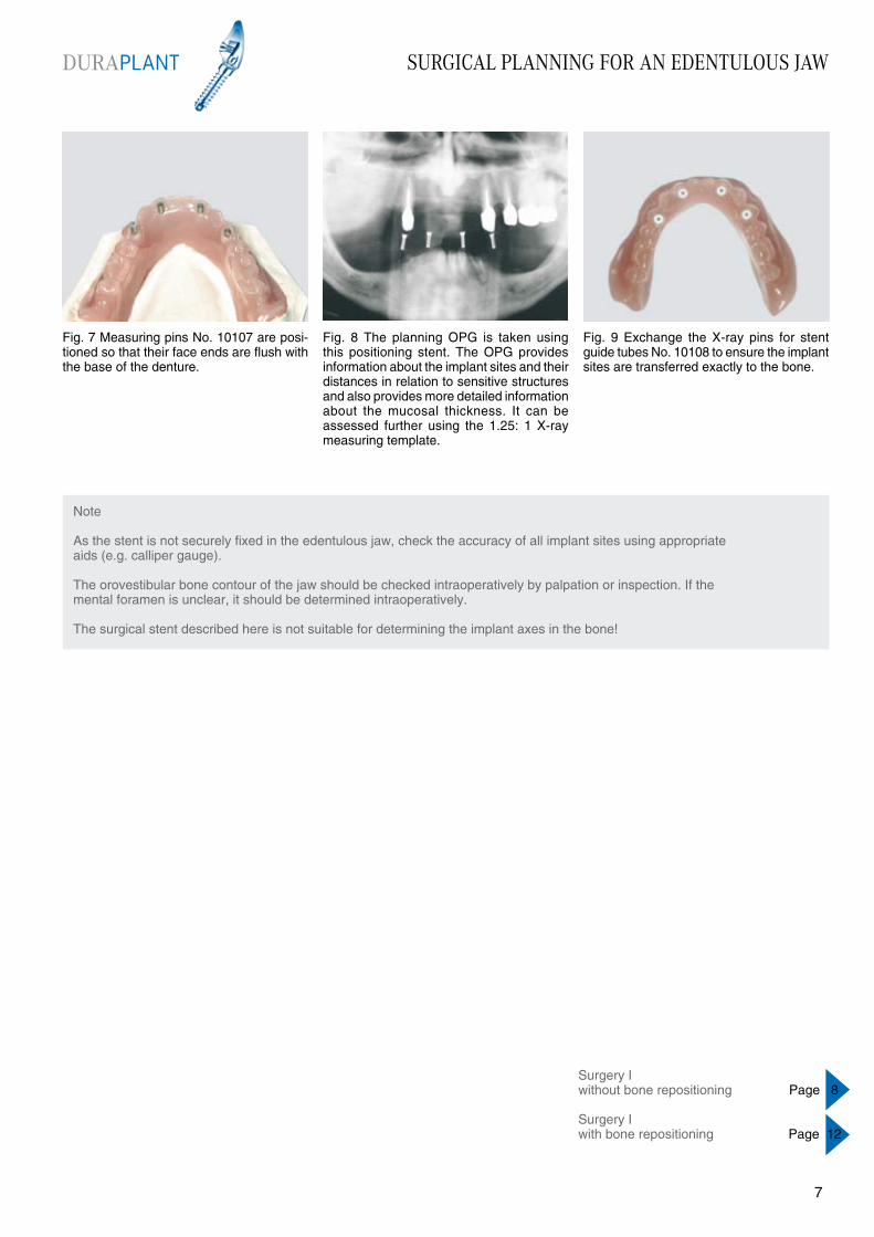
Fig. 7 Measuring pins No. 10107 are posi-tioned so that their face ends are flush with the base of the denture.
Fig. 8 The planning OPG is taken using this positioning stent. The OPG provides information about the implant sites and their distances in relation to sensitive structures and also provides more detailed information about the mucosal thickness. It can be assessed further using the 1.25: 1 X-ray measuring template.
Fig. 9 Exchange the X-ray pins for stent guide tubes No. 10108 to ensure the implant sites are transferred exactly to the bone.
Note
As the stent is not securely fixed in the edentulous jaw, check the accuracy of all implant sites using appropriate aids (e.g. calliper gauge).
The orovestibular bone contour of the jaw should be checked intraoperatively by palpation or inspection. If the mental foramen is unclear, it should be determined intraoperatively.
The surgical stent described here is not suitable for determining the implant axes in the bone!
DURAPLANT
76
Surgery Iwithout bone repositioning Page 8
Surgery Iwith bone repositioning Page 12

SURGERY I WITHOUT BONE REPOSITIONING
Fig. 4 Centre the surgical stent with guide tubes using the opposing bite/denture and then mark the intended positions of the implant sites on the surface with an externally cooled pilot drill (approx. 800 rpm).
Fig. 1 Incise along the alveolar ridge from tooth 35 to 45. Make an incision towards the lingual at the uppermost mental foramen. If necessary, the mental nerve is exposed taking the usual precautionary measures.
Fig. 3 If necessary, smooth the crest of the alveolar bone with a pear-shaped bone cutter to create a plateau at least 4.9 mm wide. Always collect the bone chips in a bone filter for possible augmentation at a later stage.
Fig. 5 As a surgical stent cannot be positioned accurately enough in an edentulous jaw, each implant site should be checked for accuracy, e.g. with a calliper gauge (distance between implants, symmetrical distribution to the median line: position at tooth areas 44, 42, 32 and 34).
Fig. 6 This procedure is used to position all the pilot drill holes. The axes of the holes should be aligned to make full use of the maximum available vertical bone. The holes are then drilled to the required depth with an externally cooled ...
Fig. 2 Raise the mucosa and periosteum from the bone. Since perforation of the crestal cortical bone is often associated with granular tissue, it is advisable to prepare a tunnel on the intact vestibular cortical bone.
A local infiltration anaesthetic is used when placing implants. Any residual sensitivity does not, however, safeguard against encroaching too closely on the inferior alveolar nerve or the mental foramen. When placing implants in the mandible base (interforamen region) additional, deep (extraorally perceptible) anaesthetic depots should be placed intraorally at the base of the mandible. When placing implants close to the nasal floor, it is advisable to spray a few times with an anaesthetic spray into the lower nasal aperture. Maintain a safe distance of 2 mm above the mandibular canal (TETSCH 1984,GRAF and KNÖFLER 1986). The walls of the implant site should be 1 mm thick (TETSCH 1984). The distal edge of an implant site should not be any closer than 5 mm to the mental foramen visible on the X-ray if the mental foramen has not been determined intraoperatively and probed with a blunt instrument (Note:3 - 5 mm “mental foramen knee”; ULM et al. 1990, TATUM and LEBOWITZ 1991).
Planning OPG with exposed X-ray/surgical stent
X-ray/surgical stent; X-ray markers have been replaced with stent guide tubes
Tray 1 No. 11050 complete with a standard osteotome set
Tray 2 No. 11020 or Tray 4 No.11040, depending on the implant diameter selected
Implants comply with planning and safety requirements
DURAPLANT
98
SURGERY I WITHOUT BONE REPOSITIONING
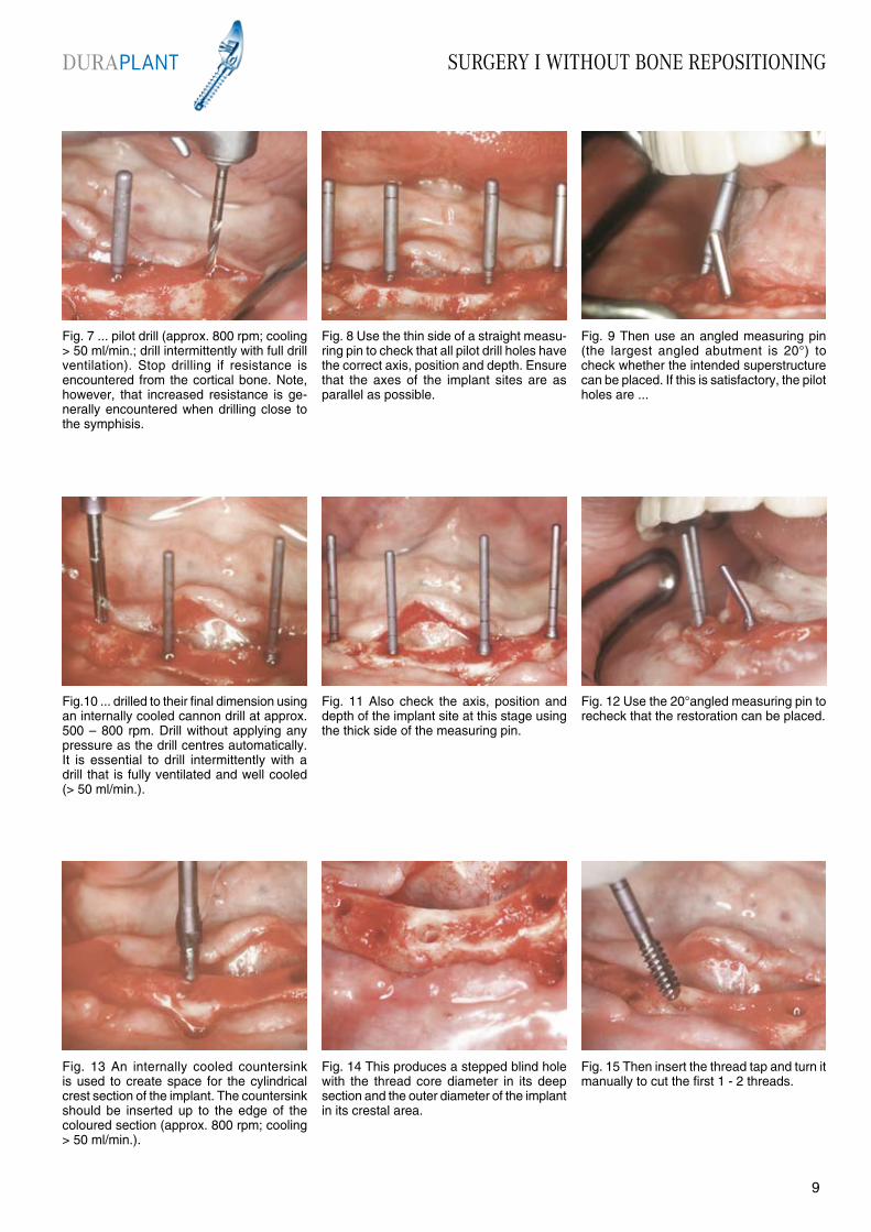
Fig. 7 ... pilot drill (approx. 800 rpm; cooling > 50 ml/min.; drill intermittently with full drill ventilation). Stop drilling if resistance is encountered from the cortical bone. Note, however, that increased resistance is ge-nerally encountered when drilling close to the symphisis.
Fig. 8 Use the thin side of a straight measu-ring pin to check that all pilot drill holes have the correct axis, position and depth. Ensure that the axes of the implant sites are as parallel as possible.
Fig. 9 Then use an angled measuring pin (the largest angled abutment is 20°) to check whether the intended superstructure can be placed. If this is satisfactory, the pilot holes are ...
Fig.10 ... drilled to their final dimension using an internally cooled cannon drill at approx. 500 – 800 rpm. Drill without applying any pressure as the drill centres automatically. It is essential to drill intermittently with a drill that is fully ventilated and well cooled (> 50 ml/min.).
Fig. 11 Also check the axis, position and depth of the implant site at this stage using the thick side of the measuring pin.
Fig. 14 This produces a stepped blind hole with the thread core diameter in its deep section and the outer diameter of the implant in its crestal area.
Fig. 13 An internally cooled countersink is used to create space for the cylindrical crest section of the implant. The countersink should be inserted up to the edge of the coloured section (approx. 800 rpm; cooling > 50 ml/min.).
Fig. 12 Use the 20°angled measuring pin to recheck that the restoration can be placed.
Fig. 15 Then insert the thread tap and turn it manually to cut the first 1 - 2 threads.
DURAPLANT
98

SURGERY I WITHOUT BONE REPOSITIONING
Fig. 22 This stage can also be completed using a handpiece with a specially designed adaptor, but always make fine adjustments to the insertion height with a ratchet, as this is more precise and involves less risk.(NOTE: risk of the threads being stripped!)
Fig. 19 Use the cap to wind the implant in a few threads without setting the implant down or touching it beforehand. Once it is securely fitted, ...
Fig. 21 The ratchet and centring head of the ring spanner are used to wind the implant in fully. Remember that the ratchet can exert great force, so take extreme care when winding in the implant to prevent stripping the threads.
Fig. 23 The implants have been inserted correctly when the ring marking on the placement aid is level with the bone. Deeper insertion can have aesthetic advantages, but there is the risk of bone growing over the healing cap.
Fig. 24 Grip the placement aid with the ring spanner and remove the placement aid retention screw using an S1 manual screwdriver. The placement aid can then be removed.
Fig. 20 ...bend and remove the silicone cap. The ring marking on the placement aid indicates the standard insertion depth.
Fig. 16 If a manual thread tapping technique is preferred, attach the ratchet and ring spanner (centring head) to the thread tap. The implant site should be cut slowly and, if necessary, rinsed intermittently to avoid overheating the bone wall.
Fig. 17 The thread can also be cut using a handpiece with a specially designed adaptor. This is recommended only for experienced operators, only in soft bone and only with a high-torque motor.
Fig. 18 After rinsing the implant site thoroughly and allowing it to fill with blood, remove the implant from the sterile packaging, ensuring that it does not become contaminated.
DURAPLANT
1110

SURGERY I WITHOUT BONE REPOSITIONING
Fig. 25 The placement aid can also be removed mechanically using an S1M screwdriver. The ring spanner is again used to grip the placement aid.
Fig. 26 After removing the placement aid, the upper edges of the implant hexagons are approximately level with the bone.
Fig. 27 Place the healing cap on the healing cap holder in tray 2 or 3 and pick it up with an S2 manual screwdriver.
Fig. 28 The easiest method of winding on the healing cap is to turn it slightly anti-clockwise. A light click indicates when the thread is engaged. No force should be required to wind on the healing cap!
Fig. 29 Healing caps should never be wound on using an S2 handpiece instrument. A contra-angle handpiece does not ensure the required sensitivity and the inner thread of the implant might be destroyed!
Fig. 32 Section of the final check X-ray (OPG).
Fig. 31 The wound is closed using atraumatic sutures (e.g. Prolene 5-0), which should be removed after 7 – 10 days (depending on the location). During this period the patient must not wear a denture. For the remaining healing period the denture should be relieved as much as possible.
Fig. 30 The implants have been inserted to the correct height and the healing caps are in situ. It is essential to insert healing caps, as this is the only means of preventing bone growing over the horizontal surface of the implant. The wound is then thoroughly cleansed.
It has been proved that after 30 days implants with a Ticer“ surface have more than twice the bone contact than that achieved by titanium.We recommend that this increased bone healing rate is used to provide greater reliability for the patient rather than to shorten the healing period. Adhere to a healing period of 180 days for the upper jaw and 90 days for the lower jaw. The healing period can always be reduced, but this increases the risks.
Temporary treatment following implantation Page 14
DURAPLANT
1110
SURGERY I USING A BONE SPIDER
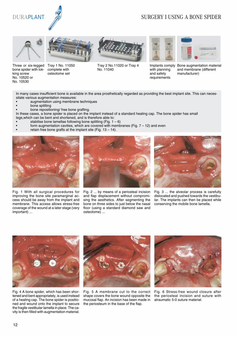
Fig. 4 A bone spider, which has been shor-tened and bent appropriately, is used instead of a healing cap. The bone spider is positio-ned and wound onto the implant to secure the fragile vestibular lamella in place. The ca-vity is then filled with augmentation material.
Fig. 1 With all surgical procedures for improving the bone site paramarginal ac-cess should be away from the implant and membrane. This access allows stress-free coverage of the wound at a later stage (very important) ...
Fig. 3 ... the alveolar process is carefully dislocated and pushed towards the vestibu-lar. The implants can then be placed while conserving the mobile bone lamella.
Fig. 5 A membrane cut to the correct shape covers the bone wound opposite the mucosal flap. An incision has been made in the periosteum in the base of the flap.
Fig. 6 Stress-free wound closure after the periosteal incision and suture with atraumatic 5-0 suture material.
Fig. 2 ... by means of a periosteal incision and flap displacement without compromi-sing the aesthetics. After segmenting the bone on three sides to just below the nasal floor (using a standard diamond saw and osteotome) ...
In many cases insufficient bone is available in the area prosthetically regarded as providing the best implant site. This can neces-sitate various augmentation measures:• augmentation using membrane techniques• bone splitting• bone repositioning/ free bone grafting.In these cases, a bone spider is placed on the implant instead of a standard healing cap. The bone spider has small legs,which can be bent and shortened, and is therefore able to:• stabilise bone lamellae following bone splitting (Fig. 1 – 6)• form augmentation cavities, which are covered with membranes (Fig. 7 – 12) and even• retain free bone grafts at the implant site (Fig. 13 – 14).
Three or six-legged bone spider with lok-king screw No. 10520 or No. 10530
Tray 2 No.11020 or Tray 4 No. 11040
Implants comply with planning and safety requirements
Bone augmentation material and membrane (different manufacturer)
Tray 1 No. 11050 complete with osteotome set
DURAPLANT
1312
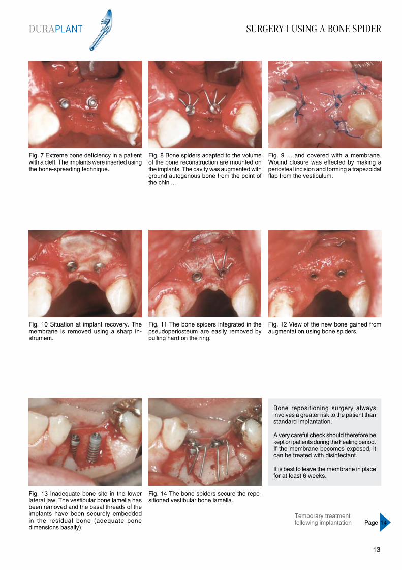
Fig. 7 Extreme bone deficiency in a patient with a cleft. The implants were inserted using the bone-spreading technique.
Fig. 8 Bone spiders adapted to the volume of the bone reconstruction are mounted on the implants. The cavity was augmented with ground autogenous bone from the point of the chin ...
Fig. 9 ... and covered with a membrane. Wound closure was effected by making a periosteal incision and forming a trapezoidal flap from the vestibulum.
Fig. 10 Situation at implant recovery. The membrane is removed using a sharp in-strument.
Fig. 11 The bone spiders integrated in the pseudoperiosteum are easily removed by pulling hard on the ring.
Fig. 14 The bone spiders secure the repo-sitioned vestibular bone lamella.
Fig. 13 Inadequate bone site in the lower lateral jaw. The vestibular bone lamella has been removed and the basal threads of the implants have been securely embedded in the residual bone (adequate bone dimensions basally).
Fig. 12 View of the new bone gained from augmentation using bone spiders.
Bone repositioning surgery always involves a greater risk to the patient than standard implantation.
A very careful check should therefore be kept on patients during the healing period. If the membrane becomes exposed, it can be treated with disinfectant.
It is best to leave the membrane in place for at least 6 weeks.
SURGERY I USING A BONE SPIDERDURAPLANT
1312
Temporary treatment following implantation Page 14
TEMPORARY TREATMENT FOLLOWING IMPLANT PLACEMENT
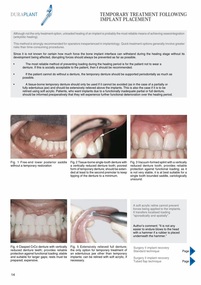
Fig. 4 Clasped CrCo denture with vertically reduced denture teeth; provides reliable protection against functional loading; stable and suitable for larger gaps; rests must be prepared; expensive.
Fig. 1 Free-end lower posterior saddle without a temporary restoration
Fig. 3 Vacuum-formed splint with a vertically reduced denture tooth; provides reliable protection against functional loading; as it is not very stable, it is at best suitable for a single tooth bounded saddle, cariologically unsound.
Fig. 5 Extensively relieved full denture; the only option for temporary treatment of an edentulous jaw other than temporary implants; can be relined with soft acrylic, if necessary.
A soft acrylic reline cannot prevent forces being applied to the implants. It transfers localised loading “sporadically and spatially”.
Author’s comment: “It is not any easier to endure blows to the head with a hammer if a rubber is placed underneath the hammer.”
Fig. 2 Tissue-borne single-tooth denture with a vertically reduced denture tooth; poorest form of temporary denture; should be exten-ded at least to the second premolar to keep tipping of the denture to a minimum.
Although not the only treatment option, unloaded healing of an implant is probably the most reliable means of achieving osseointegration (ankylotic healing).
This method is strongly recommended for operators inexperienced in implantology. Quick treatment options generally involve greater risks than time-consuming procedures.
Since it is not known for certain how much force the bone implant interface can withstand during the healing stage without its development being affected, disrupting forces should always be prevented as far as possible.
• The most reliable method of preventing loading during the healing period is for the patient not to wear a denture. If this is socially acceptable to the patient, then it should be recommended.
• If the patient cannot do without a denture, the temporary denture should be supported periodontally as much as possible.
• A tissue-borne temporary denture should only be used if it cannot be avoided (as in the case of a partially or fully edentulous jaw) and should be extensively relieved above the implants. This is also the case if it is to be relined using soft acrylic. Patients, who want implants due to a functionally inadequate partial or full denture, should be informed preoperatively that they will experience further functional deterioration over the healing period.
Surgery II implant recoveryStandard technique Page 15
Surgery II implant recoveryTubed flap technique Page 17
DURAPLANT
1514
SURGERY II IMPLANT RECOVERY STANDARD TECHNIQUE
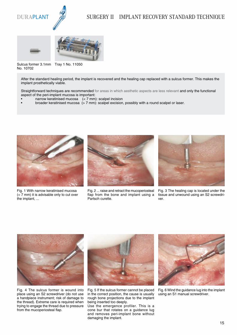
Fig. 4 The sulcus former is wound into place using an S2 screwdriver (do not use a handpiece instrument; risk of damage to the thread). Extreme care is required when trying to engage the thread due to pressure from the mucoperiosteal flap.
Fig. 1 With narrow keratinised mucosa(< 7 mm) it is advisable only to cut over the implant, ...
Fig. 3 The healing cap is located under the tissue and unwound using an S2 screwdri-ver.
Fig. 5 If the sulcus former cannot be placed in the correct position, the cause is usually rough bone projections due to the implant being inserted too deeply. Use the emergence profiler. This is a cone bur that rotates on a guidance lug and removes peri-implant bone without damaging the implant.
Fig. 6 Wind the guidance lug into the implant using an S1 manual screwdriver.
Fig. 2 ... raise and retract the mucoperiosteal flap from the bone and implant using a Partsch curette.
After the standard healing period, the implant is recovered and the healing cap replaced with a sulcus former. This makes the implant prosthetically viable.
Straightforward techniques are recommended for areas in which aesthetic aspects are less relevant and only the functional aspect of the peri-implant mucosa is important:• narrow keratinised mucosa (< 7 mm): scalpel incision• broader keratinised mucosa (> 7 mm): scalpel excision, possibly with a round scalpel or laser.
Sulcus former 3.1mm No. 10702
Tray 1 No. 11050
DURAPLANT
1514
SURGERY II IMPLANT RECOVERY STANDARD TECHNIQUE
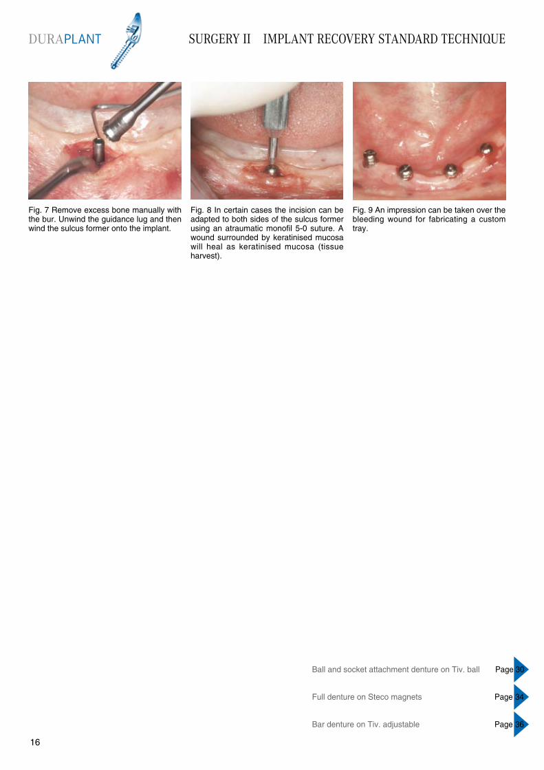
Fig. 7 Remove excess bone manually with the bur. Unwind the guidance lug and then wind the sulcus former onto the implant.
Fig. 8 In certain cases the incision can be adapted to both sides of the sulcus former using an atraumatic monofil 5-0 suture. A wound surrounded by keratinised mucosa will heal as keratinised mucosa (tissue harvest).
Fig. 9 An impression can be taken over the bleeding wound for fabricating a custom tray.
Ball and socket attachment denture on Tiv. ball Page 30
Full denture on Steco magnets Page 34
Bar denture on Tiv. adjustable Page 36
DURAPLANT
1716
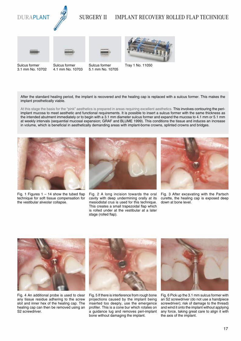
Fig. 4 An additional probe is used to clear any tissue residue adhering to the screw slot and inner hex of the healing cap. The healing cap can then be removed using an S2 screwdriver.
After the standard healing period, the implant is recovered and the healing cap is replaced with a sulcus former. This makes the implant prosthetically viable.
At this stage the basis for the “pink” aesthetics is prepared in areas requiring excellent aesthetics. This involves contouring the peri-implant mucosa to meet aesthetic and functional requirements. It is possible to insert a sulcus former with the same thickness as the intended abutment immediately or to begin with a 3.1 mm diameter sulcus former and expand the mucosa to 4.1 mm or 5.1 mm at weekly intervals (sequential mucosal expansion; GRAF and BLUME 1999). This conditions the tissue and induces an increase in volume, which is beneficial in aesthetically demanding areas with implant-borne crowns, splinted crowns and bridges.
Fig. 1 Figures 1 – 14 show the tubed flap technique for soft tissue compensation for the vestibular alveolar collapse.
Fig. 3 After excavating with the Partsch curette, the healing cap is exposed deep down at bone level.
Fig. 5 If there is interference from rough bone projections caused by the implant being inserted too deeply, use the emergence profiler. This is a cone bur which rotates on a guidance lug and removes peri-implant bone without damaging the implant.
Fig. 6 Pick up the 3.1 mm sulcus former with an S2 screwdriver (do not use a handpiece screwdriver); risk of damage to the thread) and wind it onto the implant without applying any force, taking great care to align it with the axis of the implant.
Fig. 2 A long incision towards the oral cavity with deep undermining orally at its mesiodistal crus is used for this technique. This creates a small trapezoidal flap which is rolled under at the vestibular at a later stage (rolled flap).
Sulcus former 3.1 mm No. 10702
Sulcus former 4.1 mm No. 10703
Sulcus former 5.1 mm No. 10705
Tray 1 No. 11050
DURAPLANT SURGERY II IMPLANT RECOVERY ROLLED FLAP TECHNIQUE
1716
SURGERY II IMPLANT RECOVERY ROLLED FLAP TECHNIQUE
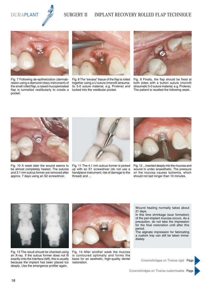
Fig. 7 Following de-epithelization (dermab- rasion using a diamond rotary instrument) of the small rolled flap, a raised mucoperiosteal flap is tunnelled vestibularly to create a pocket.
Fig. 8 The “excess” tissue of the flap is rolled together using a U suture (monofil atrauma-tic 5-0 suture material, e.g. Prolene) and tucked into the vestibular pocket.
Fig. 9 Finally, the flap should be fixed at both sides with a button suture (monofil atraumatic 5-0 suture material, e.g. Prolene). The patient is recalled the following week.
Fig. 10 A week later the wound seems to be almost completely healed. The sutures and 3.1 mm sulcus former are removed after approx. 7 days using an S2 screwdriver.
Fig. 11 The 4.1 mm sulcus former is picked up with an S1 screwdriver (do not use a handpiece instrument; risk of damage to the thread) and ...
Fig. 14 After another week the mucosa is contoured optimally and forms the basis for an aesthetic, high-quality dental restoration.
Fig. 13 The result should be checked using an X-ray. If the sulcus former does not fit exactly onto the interface (left), this is usually because the implant has been placed too deeply. Use the emergence profiler again.
Fig. 12 ...inserted deeply into the mucosa and wound in under anaesthetic. The pressure on the mucosa causes ischemia, which should not last longer than 10 minutes.
Wound healing normally takes about 21 days.In this time shrinkage (scar formation) of the peri-implant mucosa occurs. As a precaution, do not take the impression for the final restoration until after this period. The alginate impression for fabricating a custom tray can still be taken imme-diately.
Crowns/bridges on Tiversa rigid Page 20
Crowns/bridges on Tiversa customisable Page 25
DURAPLANT
1918
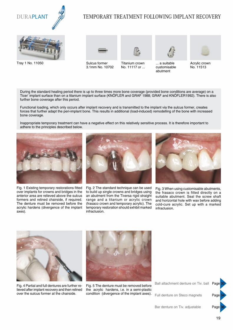
TEMPORARY TREATMENT FOLLOWING IMPLANT RECOVERY
During the standard healing period there is up to three times more bone coverage (provided bone conditions are average) on a Ticer“ implant surface than on a titanium implant surface (KNÖFLER and GRAF 1988; GRAF and KNÖFLER1992). There is also further bone coverage after this period.
Functional loading, which only occurs after implant recovery and is transmitted to the implant via the sulcus former, creates forces that further adapt the peri-implant bone. This results in additional (load-induced) remodelling of the bone with increased bone coverage.
Inappropriate temporary treatment can have a negative effect on this relatively sensitive process. It is therefore important to adhere to the principles described below.
Fig. 1 Existing temporary restorations fitted over implants for crowns and bridges in the anterior area are relieved above the sulcus formers and relined chairside, if required. The denture must be removed before the acrylic hardens (divergence of the implant axes).
Fig. 2 The standard technique can be used to build up single crowns and bridges using an abutment from the Tiversa rigid straight range and a titanium or acrylic crown (frasaco crown and temporary acrylic). The temporary restoration should exhibit marked infraclusion.
Fig. 5 The denture must be removed before the acrylic hardens, i.e. in a semi-plastic condition (divergence of the implant axes).
Fig. 4 Partial and full dentures are further re-lieved after implant recovery and then relined over the sulcus former at the chairside.
Fig. 3 When using customisable abutments, the frasaco crown is fitted directly on a suitable abutment. Seal the screw shaft and horizontal hole with wax before adding cold-cure acrylic. Set up with a marked infraclusion.
Tray 1 No. 11050 Titanium crown No. 11117 or ...
... a suitable customisable abutment
Sulcus former 3.1mm No. 10702
Acrylic crown No. 11513
DURAPLANT
1918
Ball attachment denture on Tiv. ball Page 30
Full denture on Steco magnets Page 34
Bar denture on Tiv. adjustable Page 36
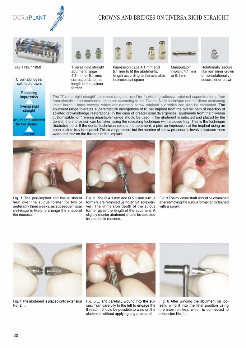
CROWNS AND BRIDGES ON TIVERSA RIGID STRAIGHT
Fig. 1 The peri-implant soft tissue should heal over the sulcus former for two or preferably three weeks, as subsequent scar shrinkage is likely to change the shape of the mucosa.
Fig. 2 The Ø 4.1 mm and Ø 5.1 mm sulcus formers are removed using an S1 screwdri-ver. The immersion depth of the sulcus former gives the length of the abutment. A slightly shorter abutment should be selected for aesthetic reasons.
Fig. 5 ... and carefully wound into the sul-cus. Turn carefully to the left to engage the thread. It should be possible to wind on the abutment without applying any pressure!
Fig. 4 The abutment is placed onto extension No. 2 ...
Fig. 3 The mucosal shaft should be examined after removing the sulcus former and cleaned with a spray.
The “Tiversa rigid straight” abutment range is used for fabricating adhesive-retained superstructures free from electrical and mechanical stresses according to the Tiversa-Nefis technique and for direct contouring using burnout inner crowns, which are normally screw-retained but which can also be cemented. The abutment range tolerates superstructure divergences of 6° per implant from the overall path of insertion of splinted crowns/bridge restorations. In the case of greater axial divergences, abutments from the “Tiversa customisable” or “Tiversa adjustable” range should be used. If the abutment is selected and placed by the dentist, the impression can be taken using the reseating technique with a closed tray. This is the technique illustrated here. If the dental technician selects the abutment, a pick-up impression at the implant using an open custom tray is required. This is very precise, but the number of screw procedures involved causes more wear and tear on the threads of the implant.
Fig. 6 After winding the abutment on loo-sely, wind it into the final position using the insertion key, which is connected to extension No. 1.
Crowns/bridges/ splinted crowns
Implant
Reseating impression
Tiversa rigid straight
Abutments selected by the dentist
Tray 1 No. 11050 Tiversa rigid straight abutment range 4.1 mm or 5.1 mm; corresponds to the length of the sulcus former
Impression caps 4.1 mm and 5.1 mm to fit the abutments; length according to the available interocclusal space
Manipulator implant 4.1 mmor 5.1 mm
Rotationally secure titanium inner crown or nonrotationally secure inner crown
DURAPLANT
2120

Fig. 13 An arbitrary registration should be taken for all implant prosthetic restorations.
Fig. 14 An appropriate titanium inner crown or acrylic crown and a frasaco crown are used ...
Fig. 15 ... to fabricate a temporary restoration.
CROWNS AND BRIDGES ON TIVERSA RIGID STRAIGHT
Fig. 10 If the X-ray check shows the abutment is in the correct position, tighten it securely using the socket spanner and 20 Ncm torque wrench. The torque wrench should click twice.
NOTE: Torque wrenches do not have a reverse function and must be turned over.
Fig. 11 Impression cap No. 10140 or 10143 for the reseating impression. If possible, the long cap should be used (provided there is adequate interocclusal space) with its taper facing lingually or orally.
Fig. 12 Take a one-step putty-wash impres-sion. The impression caps should be marked according to their position when taking an impression for splinted crowns or bridges, as this is more precise.
Fig. 7 The outer hexagon of the socket spanner grips the abutment base and is used to turn it. The inner tube grips the abutment screw and is used to tighten the abutment.
Fig. 9 The result is checked with an X-ray. If the abutment and implant do not fit as well as shown on the right of the illustration, turn carefully again and tighten further to attain the correct position.
Fig. 8 Turn the handle carefully to rotate the abutment base so that it slides onto the implant hex. The central screw should be carefully tightened at the same time using the right hand (extension No. 1).
Tray 1 No. 11050 Tiversa rigid straight abutment range 4.1 mm or 5.1 mm; corresponds to the length of the sulcus former
Impression caps 4.1 mm and 5.1 mm to fit the abutments; length according to the available interocclusal space
Manipulator implant 4.1 mmor 5.1 mm
Rotationally secure titanium inner crown or nonrotationally secure inner crown
DURAPLANT
2120
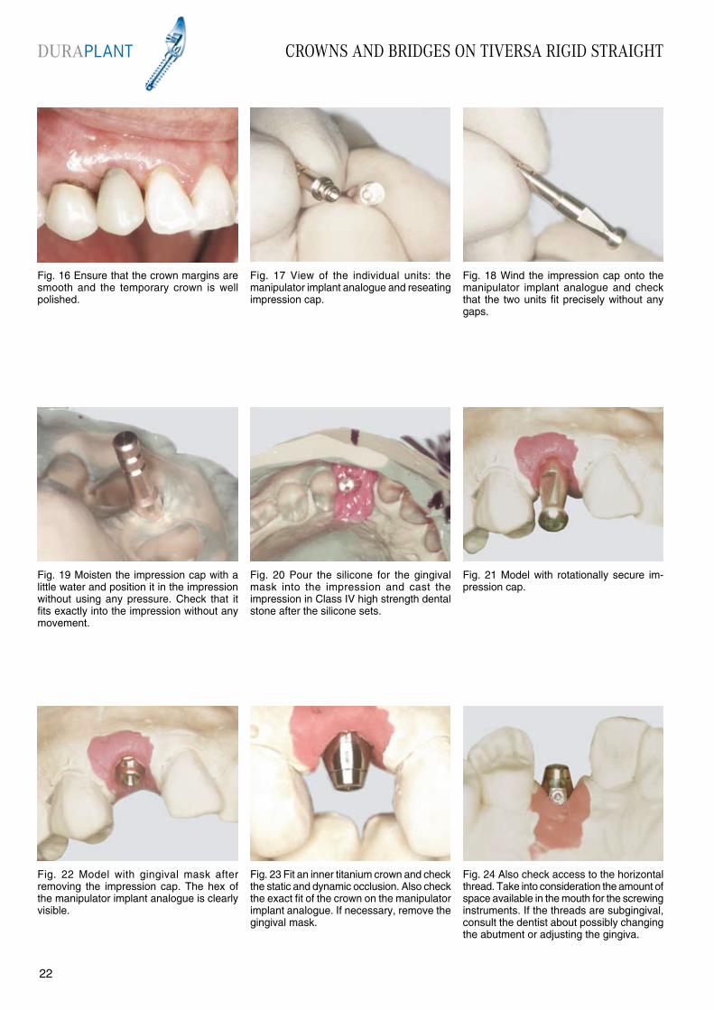
CROWNS AND BRIDGES ON TIVERSA RIGID STRAIGHT
Fig. 16 Ensure that the crown margins are smooth and the temporary crown is well polished.
Fig. 17 View of the individual units: the manipulator implant analogue and reseating impression cap.
Fig. 20 Pour the silicone for the gingival mask into the impression and cast the impression in Class IV high strength dental stone after the silicone sets.
Fig. 19 Moisten the impression cap with a little water and position it in the impression without using any pressure. Check that it fits exactly into the impression without any movement.
Fig. 18 Wind the impression cap onto the manipulator implant analogue and check that the two units fit precisely without any gaps.
Fig. 21 Model with rotationally secure im-pression cap.
Fig. 22 Model with gingival mask after removing the impression cap. The hex of the manipulator implant analogue is clearly visible.
Fig. 24 Also check access to the horizontal thread. Take into consideration the amount of space available in the mouth for the screwing instruments. If the threads are subgingival, consult the dentist about possibly changing the abutment or adjusting the gingiva.
Fig. 23 Fit an inner titanium crown and check the static and dynamic occlusion. Also check the exact fit of the crown on the manipulator implant analogue. If necessary, remove the gingival mask.
DURAPLANT
2322
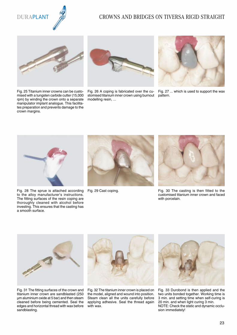
Fig. 31 The fitting surfaces of the crown and titanium inner crown are sandblasted (250 µm aluminium oxide at 5 bar) and then steam cleaned before being cemented. Seal the edges and horizontal thread with wax before sandblasting.
Fig. 32 The titanium inner crown is placed on the model, aligned and wound into position. Steam clean all the units carefully before applying adhesive. Seal the thread again with wax.
Fig. 33 Durobond is then applied and the two units bonded together. Working time is 3 min. and setting time when self-curing is 20 min. and when light curing 3 min.NOTE: Check the static and dynamic occlu-sion immediately!
CROWNS AND BRIDGES ON TIVERSA RIGID STRAIGHT
Fig. 28 The sprue is attached according to the alloy manufacturer’s instructions. The fitting surfaces of the resin coping are thoroughly cleaned with alcohol before investing. This ensures that the casting has a smooth surface.
Fig. 25 Titanium inner crowns can be custo-mised with a tungsten carbide cutter (15,000 rpm) by winding the crown onto a separate manipulator implant analogue. This facilita-tes preparation and prevents damage to the crown margins.
Fig. 27 ... which is used to support the wax pattern.
Fig. 29 Cast coping. Fig. 30 The casting is then fitted to the customised titanium inner crown and faced with porcelain.
Fig. 26 A coping is fabricated over the cu-stomised titanium inner crown using burnout modelling resin, ...
DURAPLANT
2322
CROWNS AND BRIDGES ON TIVERSA RIGID STRAIGHT
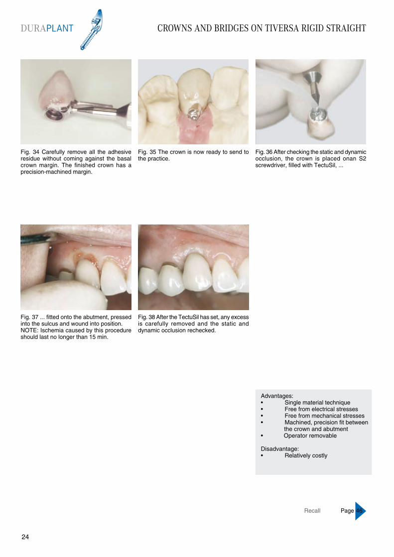
Fig. 34 Carefully remove all the adhesive residue without coming against the basal crown margin. The finished crown has a precision-machined margin.
Fig. 35 The crown is now ready to send to the practice.
Fig. 38 After the TectuSil has set, any excess is carefully removed and the static and dynamic occlusion rechecked.
Fig. 37 ... fitted onto the abutment, pressed into the sulcus and wound into position.NOTE: Ischemia caused by this procedure should last no longer than 15 min.
Fig. 36 After checking the static and dynamic occlusion, the crown is placed onan S2 screwdriver, filled with TectuSil, ...
Advantages:• Single material technique• Free from electrical stresses• Free from mechanical stresses• Machined, precision fit between the crown and abutment• Operator removable
Disadvantage:• Relatively costly
Recall Page 46
DURAPLANT
2524
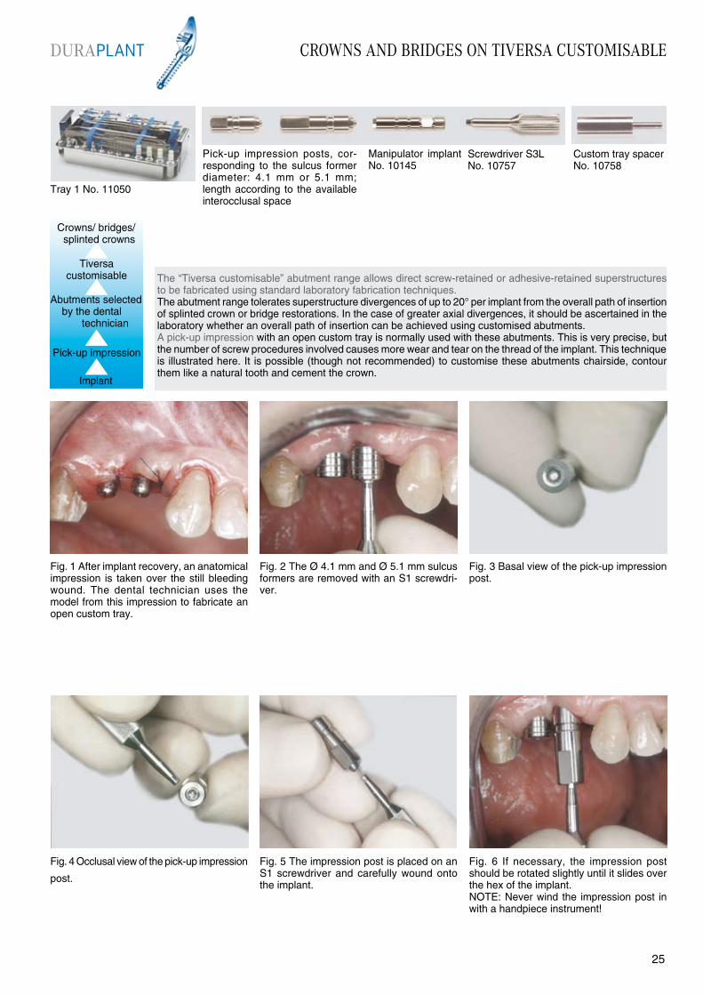
Fig. 4 Occlusal view of the pick-up impression
post.
The “Tiversa customisable” abutment range allows direct screw-retained or adhesive-retained superstructures to be fabricated using standard laboratory fabrication techniques.The abutment range tolerates superstructure divergences of up to 20° per implant from the overall path of insertion of splinted crown or bridge restorations. In the case of greater axial divergences, it should be ascertained in the laboratory whether an overall path of insertion can be achieved using customised abutments. A pick-up impression with an open custom tray is normally used with these abutments. This is very precise, but the number of screw procedures involved causes more wear and tear on the thread of the implant. This technique is illustrated here. It is possible (though not recommended) to customise these abutments chairside, contour them like a natural tooth and cement the crown.
Fig. 1 After implant recovery, an anatomical impression is taken over the still bleeding wound. The dental technician uses the model from this impression to fabricate an open custom tray.
Fig. 3 Basal view of the pick-up impression post.
Fig. 5 The impression post is placed on an S1 screwdriver and carefully wound onto the implant.
Fig. 6 If necessary, the impression post should be rotated slightly until it slides over the hex of the implant.NOTE: Never wind the impression post in with a handpiece instrument!
Fig. 2 The Ø 4.1 mm and Ø 5.1 mm sulcus formers are removed with an S1 screwdri-ver.
Tray 1 No. 11050
Pick-up impression posts, cor-responding to the sulcus former diameter: 4.1 mm or 5.1 mm; length according to the available interocclusal space
Manipulator implant No. 10145
Custom tray spacerNo. 10758
Screwdriver S3L No. 10757
Implant
Pick-up impression
Abutments selected by the dental
technician
DURAPLANT CROWNS AND BRIDGES ON TIVERSA CUSTOMISABLE
2524
Crowns/ bridges/ splinted crowns
Tiversa customisable
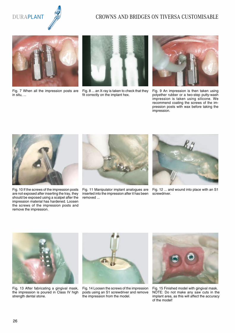
Fig. 15 Finished model with gingival mask.NOTE: Do not make any saw cuts in the implant area, as this will affect the accuracy of the model!
Fig. 7 When all the impression posts are in situ, ...
Fig. 8 ... an X-ray is taken to check that they fit correctly on the implant hex.
Fig. 9 An impression is then taken using polyether rubber or a two-step putty-wash impression is taken using silicone. We recommend coating the screws of the im-pression posts with wax before taking the impression.
Fig. 10 If the screws of the impression posts are not exposed after inserting the tray, they should be exposed using a scalpel after the impression material has hardened. Loosen the screws of the impression posts and remove the impression.
Fig. 11 Manipulator implant analogues are inserted into the impression after it has been removed ...
Fig. 14 Loosen the screws of the impression posts using an S1 screwdriver and remove the impression from the model.
Fig. 13 After fabricating a gingival mask, the impression is poured in Class IV high strength dental stone.
Fig. 12 ... and wound into place with an S1 screwdriver.
DURAPLANT CROWNS AND BRIDGES ON TIVERSA CUSTOMISABLE
2726
CROWNS AND BRIDGES ON TIVERSA CUSTOMISABLE
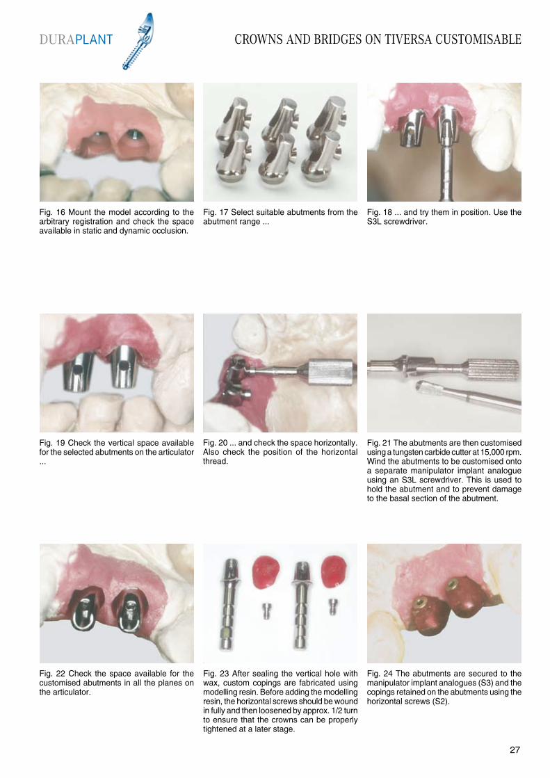
Fig. 22 Check the space available for the customised abutments in all the planes on the articulator.
Fig. 19 Check the vertical space available for the selected abutments on the articulator ...
Fig. 21 The abutments are then customised using a tungsten carbide cutter at 15,000 rpm. Wind the abutments to be customised onto a separate manipulator implant analogue using an S3L screwdriver. This is used to hold the abutment and to prevent damage to the basal section of the abutment.
Fig. 23 After sealing the vertical hole with wax, custom copings are fabricated using modelling resin. Before adding the modelling resin, the horizontal screws should be wound in fully and then loosened by approx. 1/2 turn to ensure that the crowns can be properly tightened at a later stage.
Fig. 24 The abutments are secured to the manipulator implant analogues (S3) and the copings retained on the abutments using the horizontal screws (S2).
Fig. 20 ... and check the space horizontally. Also check the position of the horizontal thread.
Fig. 16 Mount the model according to the arbitrary registration and check the space available in static and dynamic occlusion.
Fig. 18 ... and try them in position. Use the S3L screwdriver.
Fig. 17 Select suitable abutments from the abutment range ...
DURAPLANT
2726

CROWNS AND BRIDGES ON TIVERSA CUSTOMISABLE
Fig. 25 Connect the copings with resin to prevent distortion of the framework. Complete the wax-up according to the type of facing selected.
Fig. 26 Attach the sprues according to the alloy manufacturer’s instructions.
Fig. 27 After the crowns have been cast and prepared, they are tried on the model and the horizontal screws tightened (S2). The screws must operate smoothly.
Fig. 28 Apply porcelain to the framework in the usual manner. The abutments of a screw-retained restoration are polished: if the restoration is to be cemented, the surfaces that have contact with the cement are sandblasted with aluminium oxide (250µm, 2 bar). The basal sections of the abutment should be coated with wax before sandblasting.
Fig. 29 Palatal view of the finished restoration. If the screws do not operate smoothly enough, the abutment thread should be re-cut with the thread tap No. 476.
Fig. 32 ... and wound on using an S3L screwdriver.
Fig. 31 After the sulcus formers are removed, the abutments, which are secured in a placement device with horizontal screws, are fitted in the practice ...
Fig 30 Buccal view of the finished restoration. The untreated molar is not worth conserving and will be extracted after the restoration has been fitted.
Fig. 33 If necessary, an X-ray of the abut-ments should be taken to check that they fit correctly before finally tightening the screws.
DURAPLANT
2928

CROWNS AND BRIDGES ON TIVERSA CUSTOMISABLE
Fig. 40 Use a rubber polisher to ensure that the screws are flush.Note: Do not use a burnisher! This would burnish the material of the screws and could make it impossible to loosen them!
Fig. 37 ... and fitted. Fig. 39 Place the horizontal screws onto an S2 screwdriver, insert the screws and tighten them. NOTE: In awkward areas it may be necessary to use a handpiece instrument to tighten the screws. It is essential to ensure the correct thread axis is engaged.
Fig. 41 Finished restoration in the mouth. The periapically adjusted tooth 16 was no longer required and was extracted.
Fig. 38 It may be necessary to apply strong thumb pressure or use an adaptor to achieve the final position, as TectuSil is relatively highly viscous.
Fig. 34 After replacing the placement device, the central screws of the abutments are tightened using the S3L screwdriver and 20 Ncm torque wrench.Note: Torque wrenches do not have a reverse function and must be turned over!
Fig. 35 The splinted crowns are then tried in. Check the marginal seal, static and dynamic occlusion as well as ease of insertion and smooth operation of the horizontal screws.
Fig. 36 If the try-in is satisfactory, the crowns are filled with TectuSil ...
Advantages:• Compact• Customisable• Can be fabricated using standard laboratory techniques• Operator removable• Cementable• Cost-effectiveDisadvantages:• Numerous screw procedures• Technique involves more than one material
DURAPLANT
2928
Recall Page 46

FULL DENTURE ON TIVERSA BALL
Fig. 4 A No. 2 extension is added to the Tiversa ball abutment.
The “Tiversa ball” abutment range provides the most cost-effective option for retaining a denture. The abutment enables smooth positioning and allows the withdrawal force to be adjusted at any time.The use of two implants creates a functionally resilient restoration with secondary connectors. This involves relatively heavy loading of the bone particularly in the centre of masticatory loading (second premolar/ first molar region), resulting in the need for frequent relining.The use of more than two implants prevents rotational movement and creates a restoration with attachment kinematics and secondary connectors.The abutment range tolerates divergences of 20° per implant from the overall path of insertion. The impression for these abutments is normally taken statically (without impression caps) with the existing denture being used as a custom tray. This technique is illustrated here.
Fig. 1 Normally implants for this type of restoration are placed in the tooth areas 33 and 43. The arch of the lower jaw does not have to be taken into consideration, as the tongue space is not restricted by the use of a bar.
Fig. 3 Following examination of the sulcus, the mucosal shaft should be thoroughly rinsed to remove any residual tissue/necroses.
Fig. 5 This instrument is used to wind the abutment carefully in position. We recommend turning the abutment slightly to the left to engage the thread. The abutment should be wound in without any noticeable resistance (Note: fine thread).
Fig. 6 Try the matrix on the ball attachment and check whether the margins of the matrix touch the mucosa when tipped fully. Should this be the case, select the next length of abutment.
Fig. 2 The immersion depth of the sulcus former (ring marking) denotes the length of the Tiversa ball abutment to be used. The sulcus former is removed using an S2 screwdriver.
Tiversa ballretained denture
Implant
Abutments placed by the dentist
Reline impression
Tray 1 No. 11050 Activator for Tiversa ball matrix No. 10767
Tiversa ball abutments, corresponding to the mucosal height
2 Flexible spacer rings No. 142
Manipulator implant No. 10751 for Tiversa ball abutments
DURAPLANT
3130
FULL DENTURE ON TIVERSA BALL
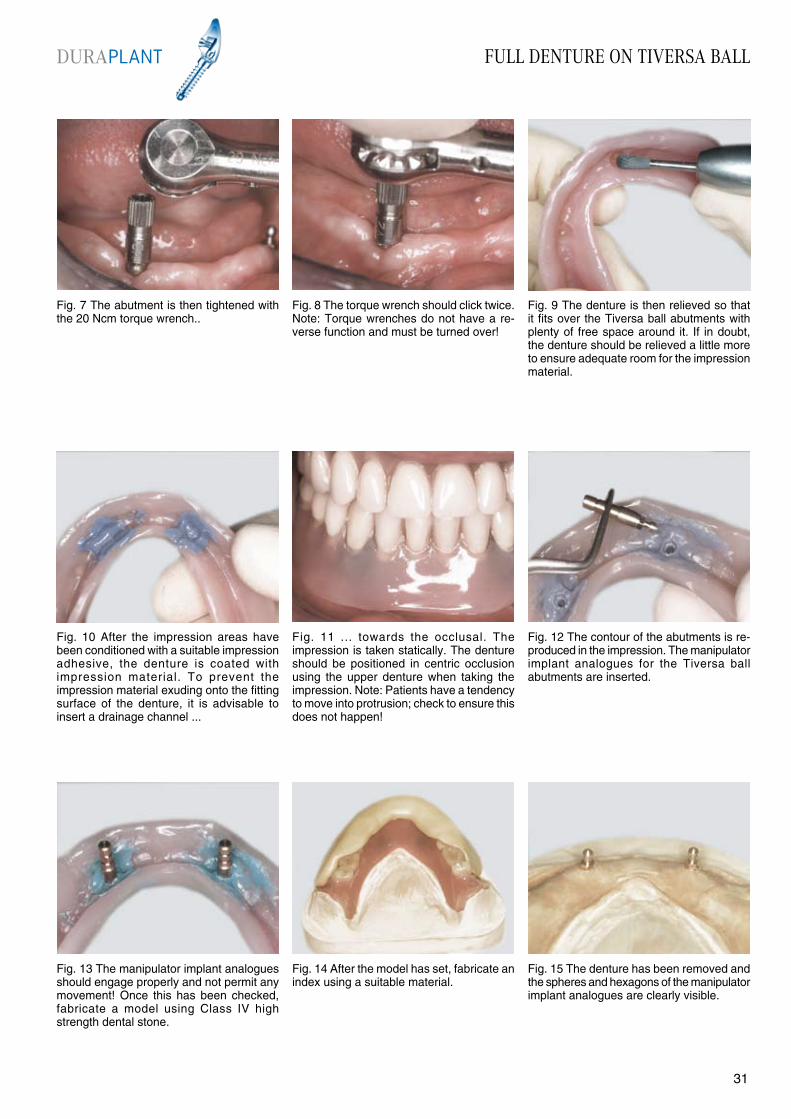
Fig. 7 The abutment is then tightened with the 20 Ncm torque wrench..
Fig. 8 The torque wrench should click twice.Note: Torque wrenches do not have a re-verse function and must be turned over!
Fig. 9 The denture is then relieved so that it fits over the Tiversa ball abutments with plenty of free space around it. If in doubt, the denture should be relieved a little more to ensure adequate room for the impression material.
Fig. 10 After the impression areas have been conditioned with a suitable impression adhesive, the denture is coated with impression material. To prevent the impression material exuding onto the fitting surface of the denture, it is advisable to insert a drainage channel ...
Fig. 11 ... towards the occlusal. The impression is taken statically. The denture should be positioned in centric occlusion using the upper denture when taking the impression. Note: Patients have a tendency to move into protrusion; check to ensure this does not happen!
Fig. 14 After the model has set, fabricate an index using a suitable material.
Fig. 13 The manipulator implant analogues should engage properly and not permit any movement! Once this has been checked, fabricate a model using Class IV high strength dental stone.
Fig. 12 The contour of the abutments is re- produced in the impression. The manipulator implant analogues for the Tiversa ball abutments are inserted.
Fig. 15 The denture has been removed and the spheres and hexagons of the manipulator implant analogues are clearly visible.
DURAPLANT
3130

FULL DENTURE ON TIVERSA BALL
Fig. 22 After finishing, secure the activation screw with TectuSil to prevent any inadvertent manipulation.
Fig. 19 Depending on the polymerisation method used (hot or cold), block out any undercut areas between the matrices and model with plaster or wax.
Fig. 21 Lift the denture from the model, remove the activation screw and plastic spacers and clean the whole matrix.
Fig. 23 Finished denture in situ.
Fig. 20 Before adding the acrylic, check to ensure there are no high spots that would prevent accurate positioning. Then add the acrylic in the usual manner.
Fig. 16 Place the deactivated matrices on the manipulator implant analogues and check their excursion options.
Fig. 17 Relieve the denture liberally in the area of the abutments. Ensure that the matrices have a free space of 0.5 mm.
Fig. 18 Place two flexible space maintainers on each manipulator implant analogue. Slightly activate the matrices and fill the inside of the matrices with silicone (e.g. Optosil light body) before placing them on the manipulator implant analogues. This prevents acrylic flowing into the matrices.
Advantages:• Cost-effective restoration• Relatively easy to clean, even for patients with poor dexterity• Does not restrict the tongue spaceDisadvantages:• Loads the distal ridge areaduring “resilient bar movements”• When implants are placed in tooth areas 33 and 43, there is a tendency for the denture to tip in protrusion. This should be counteracted by fabricating accurate functional margins
DURAPLANT
3332
Recall Page 46
FULL DENTURE ON TIVERSA BALL
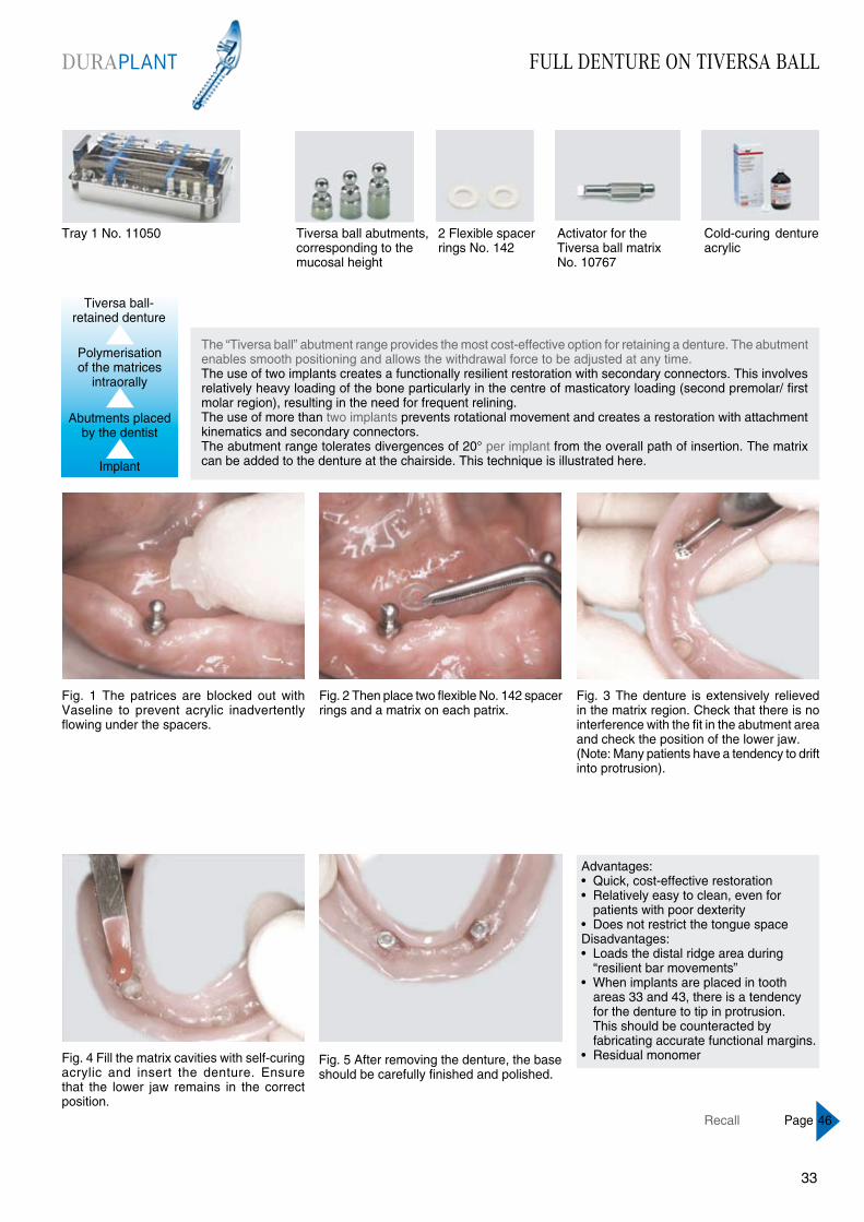
Fig. 1 The patrices are blocked out with Vaseline to prevent acrylic inadvertently flowing under the spacers.
Fig. 2 Then place two flexible No. 142 spacer rings and a matrix on each patrix.
Fig. 5 After removing the denture, the base should be carefully finished and polished.
Fig. 4 Fill the matrix cavities with self-curing acrylic and insert the denture. Ensure that the lower jaw remains in the correct position.
Fig. 3 The denture is extensively relieved in the matrix region. Check that there is no interference with the fit in the abutment area and check the position of the lower jaw.(Note: Many patients have a tendency to drift into protrusion).
The “Tiversa ball” abutment range provides the most cost-effective option for retaining a denture. The abutment enables smooth positioning and allows the withdrawal force to be adjusted at any time.The use of two implants creates a functionally resilient restoration with secondary connectors. This involves relatively heavy loading of the bone particularly in the centre of masticatory loading (second premolar/ first molar region), resulting in the need for frequent relining.The use of more than two implants prevents rotational movement and creates a restoration with attachment kinematics and secondary connectors.The abutment range tolerates divergences of 20° per implant from the overall path of insertion. The matrix can be added to the denture at the chairside. This technique is illustrated here.
Advantages:• Quick, cost-effective restoration• Relatively easy to clean, even for patients with poor dexterity• Does not restrict the tongue spaceDisadvantages:• Loads the distal ridge area during “resilient bar movements”• When implants are placed in tooth areas 33 and 43, there is a tendency for the denture to tip in protrusion. This should be counteracted by fabricating accurate functional margins.• Residual monomer
Tiversa ball-retained denture
Tray 1 No. 11050
Implant
Abutments placed by the dentist
Polymerisation of the matrices
intraorally
Activator for the Tiversa ball matrix No. 10767
Cold-curing denture acrylic
2 Flexible spacer rings No. 142
Tiversa ball abutments, corresponding to the mucosal height
DURAPLANT
3332
Recall Page 46
FULL DENTURE ON STECO MAGNETS
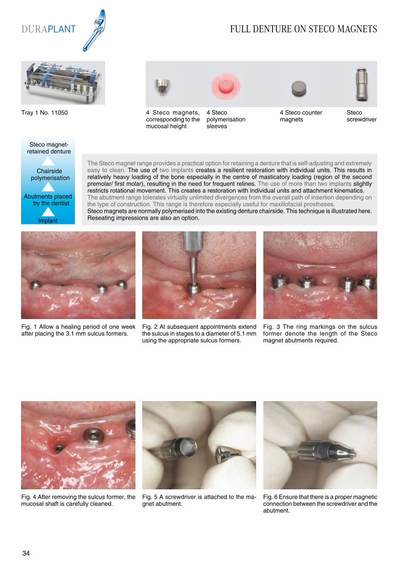
Fig. 4 After removing the sulcus former, the mucosal shaft is carefully cleaned.
The Steco magnet range provides a practical option for retaining a denture that is self-adjusting and extremely easy to clean. The use of two implants creates a resilient restoration with individual units. This results in relatively heavy loading of the bone especially in the centre of masticatory loading (region of the second premolar/ first molar), resulting in the need for frequent relines. The use of more than two implants slightly restricts rotational movement. This creates a restoration with individual units and attachment kinematics. The abutment range tolerates virtually unlimited divergences from the overall path of insertion depending on the type of construction. This range is therefore especially useful for maxillofacial prostheses.Steco magnets are normally polymerised into the existing denture chairside. This technique is illustrated here. Reseating impressions are also an option.
Fig. 1 Allow a healing period of one week after placing the 3.1 mm sulcus formers.
Fig. 3 The ring markings on the sulcus former denote the length of the Steco magnet abutments required.
Fig. 5 A screwdriver is attached to the ma-gnet abutment.
Fig. 6 Ensure that there is a proper magnetic connection between the screwdriver and the abutment.
Fig. 2 At subsequent appointments extend the sulcus in stages to a diameter of 5.1 mm using the appropriate sulcus formers.
Steco magnet- retained denture
Implant
Abutments placed by the dentist
Chairside polymerisation
Tray 1 No. 11050 4 Steco magnets, corresponding to the mucosal height
4 Steco polymerisationsleeves
Stecoscrewdriver
4 Steco counter magnets
DURAPLANT
3534
FULL DENTURE ON STECO MAGNETS
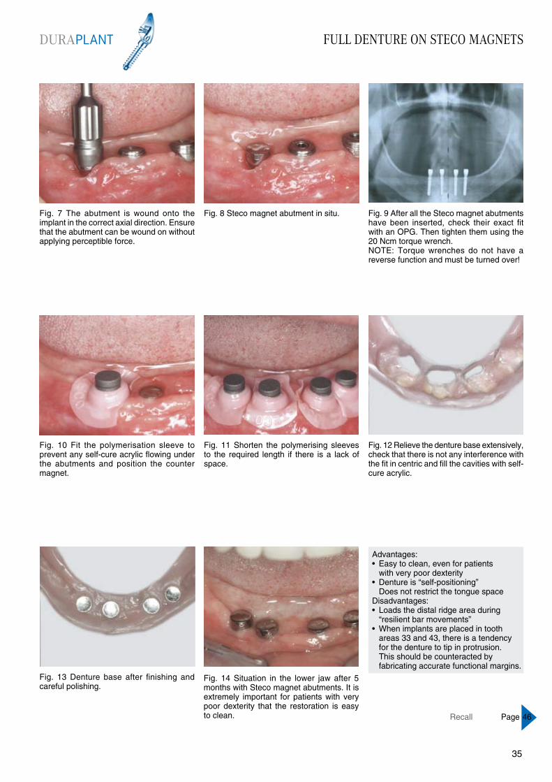
Fig. 7 The abutment is wound onto the implant in the correct axial direction. Ensure that the abutment can be wound on without applying perceptible force.
Fig. 8 Steco magnet abutment in situ. Fig. 9 After all the Steco magnet abutments have been inserted, check their exact fit with an OPG. Then tighten them using the 20 Ncm torque wrench.NOTE: Torque wrenches do not have a reverse function and must be turned over!
Fig. 10 Fit the polymerisation sleeve to prevent any self-cure acrylic flowing under the abutments and position the counter magnet.
Fig. 11 Shorten the polymerising sleeves to the required length if there is a lack of space.
Fig. 14 Situation in the lower jaw after 5 months with Steco magnet abutments. It is extremely important for patients with very poor dexterity that the restoration is easy to clean.
Fig. 13 Denture base after finishing and careful polishing.
Fig. 12 Relieve the denture base extensively, check that there is not any interference with the fit in centric and fill the cavities with self-cure acrylic.
Advantages:• Easy to clean, even for patients with very poor dexterity• Denture is “self-positioning” Does not restrict the tongue space Disadvantages:• Loads the distal ridge area during “resilient bar movements”• When implants are placed in tooth areas 33 and 43, there is a tendency for the denture to tip in protrusion. This should be counteracted by fabricating accurate functional margins.
DURAPLANT
3534
Recall Page 46

FULL DENTURE ON BAR ATTACHMENT
Fig. 4 Drill a hole in the middle of the sulcus formers on the model as shown with drill No. 10110 using a milling unit. Incline the drill hole towards the vestibular at an angle of approx. 10° - 15°.
The “Tiversa adjustable” abutment range is the ideal choice for compensating for axial divergences of up to 52° between two adjacent implants. This variability is provided by the 6° angle on each sleeve curve and a swivel range of ± 20°.The abutment is retained on the implant by friction and must be used with other implants in superstructures with primary connectors. It is intended for use with relatively thick mucosal tissue and large interocclusal spaces.It is suitable as an abutment for splinted crowns, bridges and bar restorations.
A reseating impression should be taken for this abutment.A bar attachment on four Tiversa adjustable abutments is shown below.
Fig. 1 Implants for bar attachments are normally placed in the tooth areas 34, 32, 42, and 44. The immersion depth of the sulcus former (ring marking) denotes the length of the Tiversa adjustable abutments required.
Fig. 3 Fabricate a working model. The sulcus formers on the model are used as reference points for the spacer holes.
Fig. 5 Spacer for the custom tray. This pro-vides the space required for a long Tiversa adjustable abutment, the impression cap and surrounding impression material.
Fig. 6 Drill the other drill holes as described above. Ensure that the spacers are aligned parallel to one another. Block out in the usual manner for fabricating a custom tray.
Fig. 2 After placing the Ø 3.1 mm sulcus formers, take an impression (over the bleeding wound, if necessary).
Tray 1 No. 11050; plus 60Ncm torque wrench No. 10790
Abutments placed by the dentist
Implant
bar-retained denture
Reseating impression
Tiversa adjustable abutments, corresponding tothe mucosal
Impression capsNo. 10750 orNo. 10749
Drill No. 10110 and spacer No. 10753
Gold copings No. 11735, gold bars No. 11737, activating bar sleeve No. 10740, non-activating bar sleeve No.10741
Manipulator implants No. 10752
DURAPLANT
3736
FULL DENTURE ON BAR ATTACHMENT
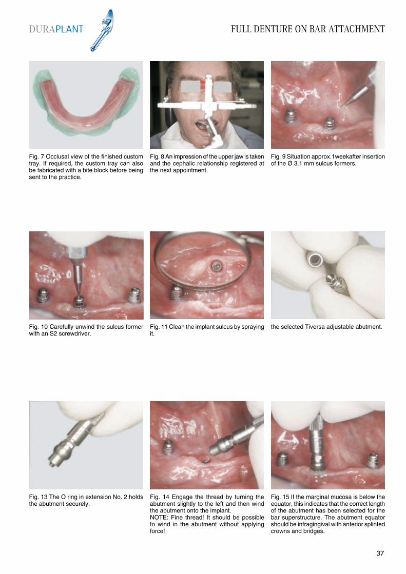
Fig. 7 Occlusal view of the finished custom tray. If required, the custom tray can also be fabricated with a bite block before being sent to the practice.
Fig. 8 An impression of the upper jaw is taken and the cephalic relationship registered at the next appointment.
Fig. 9 Situation approx.1weekafter insertion of the Ø 3.1 mm sulcus formers.
Fig. 10 Carefully unwind the sulcus former with an S2 screwdriver.
Fig. 11 Clean the implant sulcus by spraying it.
Fig. 14 Engage the thread by turning the abutment slightly to the left and then wind the abutment onto the implant.NOTE: Fine thread! It should be possible to wind in the abutment without applying force!
Fig. 13 The O ring in extension No. 2 holds the abutment securely.
the selected Tiversa adjustable abutment.
Fig. 15 If the marginal mucosa is below the equator, this indicates that the correct length of the abutment has been selected for the bar superstructure. The abutment equator should be infragingival with anterior splinted crowns and bridges.
DURAPLANT
3736
FULL DENTURE ON BAR ATTACHMENT
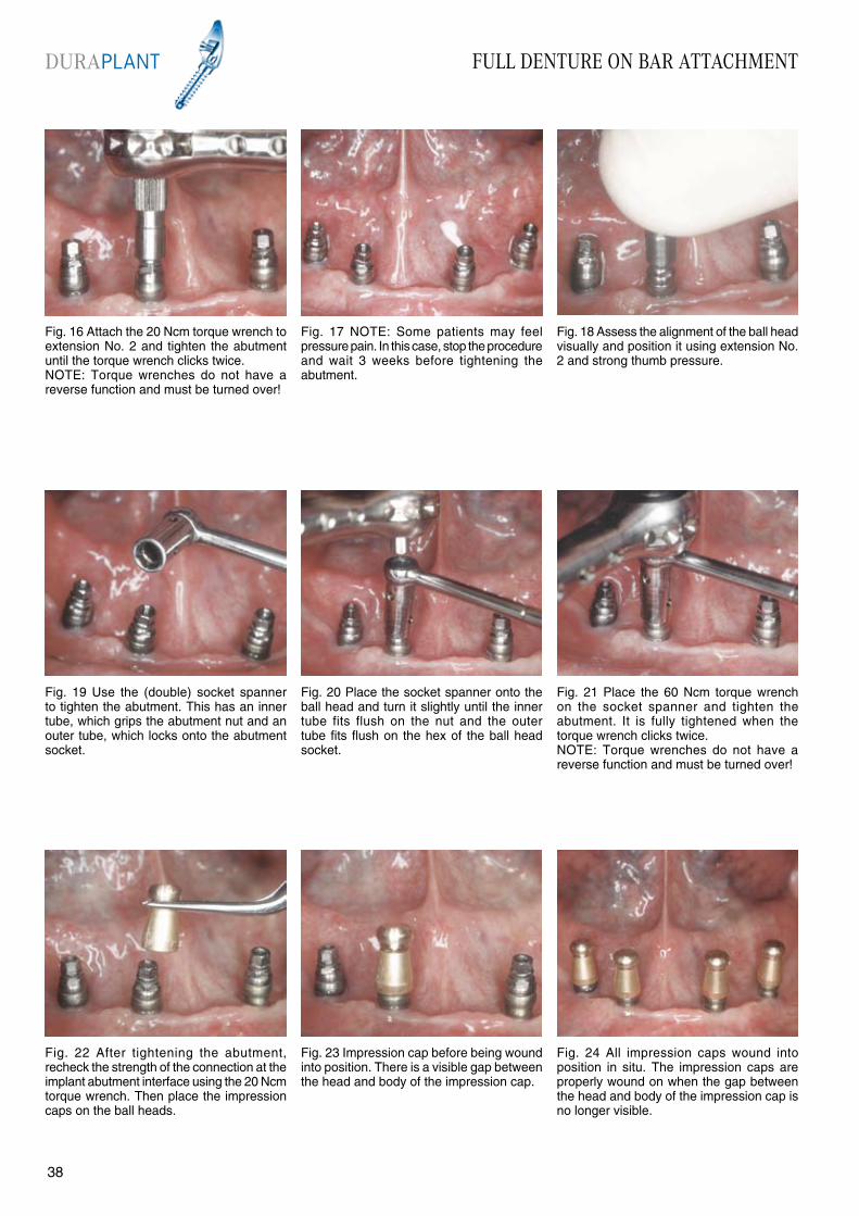
Fig. 22 After tightening the abutment, recheck the strength of the connection at the implant abutment interface using the 20 Ncm torque wrench. Then place the impression caps on the ball heads.
Fig. 19 Use the (double) socket spanner to tighten the abutment. This has an inner tube, which grips the abutment nut and an outer tube, which locks onto the abutment socket.
Fig. 21 Place the 60 Ncm torque wrench on the socket spanner and tighten the abutment. It is fully tightened when the torque wrench clicks twice. NOTE: Torque wrenches do not have a reverse function and must be turned over!
Fig. 23 Impression cap before being wound into position. There is a visible gap between the head and body of the impression cap.
Fig. 24 All impression caps wound into position in situ. The impression caps are properly wound on when the gap between the head and body of the impression cap is no longer visible.
Fig. 20 Place the socket spanner onto the ball head and turn it slightly until the inner tube fits flush on the nut and the outer tube fits flush on the hex of the ball head socket.
Fig. 16 Attach the 20 Ncm torque wrench to extension No. 2 and tighten the abutment until the torque wrench clicks twice.NOTE: Torque wrenches do not have a reverse function and must be turned over!
Fig. 18 Assess the alignment of the ball head visually and position it using extension No. 2 and strong thumb pressure.
Fig. 17 NOTE: Some patients may feel pressure pain. In this case, stop the procedure and wait 3 weeks before tightening the abutment.
DURAPLANT
3938

FULL DENTURE ON BAR ATTACHMENT
Fig. 25 Adjust the margins of the custom tray in the usual manner. Also check that the recesses for the impression caps in the custom tray fit loosely round the implants and relieve them if required.
Fig. 26 Condition the custom tray with adhesive at the saddle and functional margins, but not in the recesses. Load the conditioned areas with impression material ...
Fig. 27 ... and take a functional impression in the usual way.
Fig. 28 Then cut away the impression material in the recesses and condition these areas with adhesive.
Fig. 29 Then fill the recesses with impression material and take a second impression (static).
Fig. 32 The denture is used as a temporary restoration by extensively relieving it so that it fits over the abutments, which have been fitted with acrylic crowns No. 11511 or titanium crowns No. 11730.NOTE: The crowns must not be wound into position!
Fig. 31 We strongly recommend marking the position of the impression caps. The caps can then be replaced in exactly the same position when fabricating the model. This provides a more precise model.
Fig. 30 The impression provides information about two aspects:• the functional extension of the denture saddle• the exact (static) position of the abutments.
Fig. 33 The crowns are polymerised into the denture intraorally with self-curing resin.
DURAPLANT
3938

FULL DENTURE ON BAR ATTACHMENT
Fig. 40 Manipulator implant analogues in situ. Fabricate the models using Class IV high strength dental stone.
Fig. 37 Impression cap with a manipulator implant analogue
Fig. 39 Moisten the impression cap with a little water and position it in the impression without applying any pressure.
Fig. 41 Mount the models on the articulator and carefully remove the impression tray.
Fig. 42 Then remove the impression caps from the manipulator implant analogues.
Fig. 38 Assembled impression cap and manipulator implant analogue
Fig. 34 Block out any undercut areas with wax before polymerising the crowns into the denture. Remove the denture before the acrylic has fully polymerised.
Fig. 36 This temporary denture functions like a telescopic restoration, so carefully check the static and dynamic occlusion.
Fig. 35 Finish the base.
DURAPLANT
4140

FULL DENTURE ON BAR ATTACHMENT
Fig. 43 Bar system comprising No. 11735 gold copings, No. 11737 telescopic gold bars, No. 10740 activating bar sleeves and No. 10741 non-activating bar sleeves; No. 10729 gold bar sleeves.
Fig. 44 Place the gold copings on the mani-pulator implant analogues and tighten them using an S2 screwdriver.
Fig. 45 Measure the bar length and shorten the assembled bar to the correct length.
Fig. 46 After applying antiflux to protect the connection points of the bar matrix and patrix, place the bar between the gold copings using a paralleling mandrel ...
Fig. 47 ... and fix it in place with a suitable wax.
Fig. 50 Unwind the retention screws and remove the bar superstructure from the manipulator implant analogues.
Fig. 49 Connect the bars and gold copings together using a suitable modelling resin.
Fig. 48 Use the same procedure for all bar units.
Fig. 51 Fabricate a soldering model. The solder model should be dried in the same way as a standard casting ring. This ensures an optimal fit.
DURAPLANT
4140
FULL DENTURE ON BAR ATTACHMENT
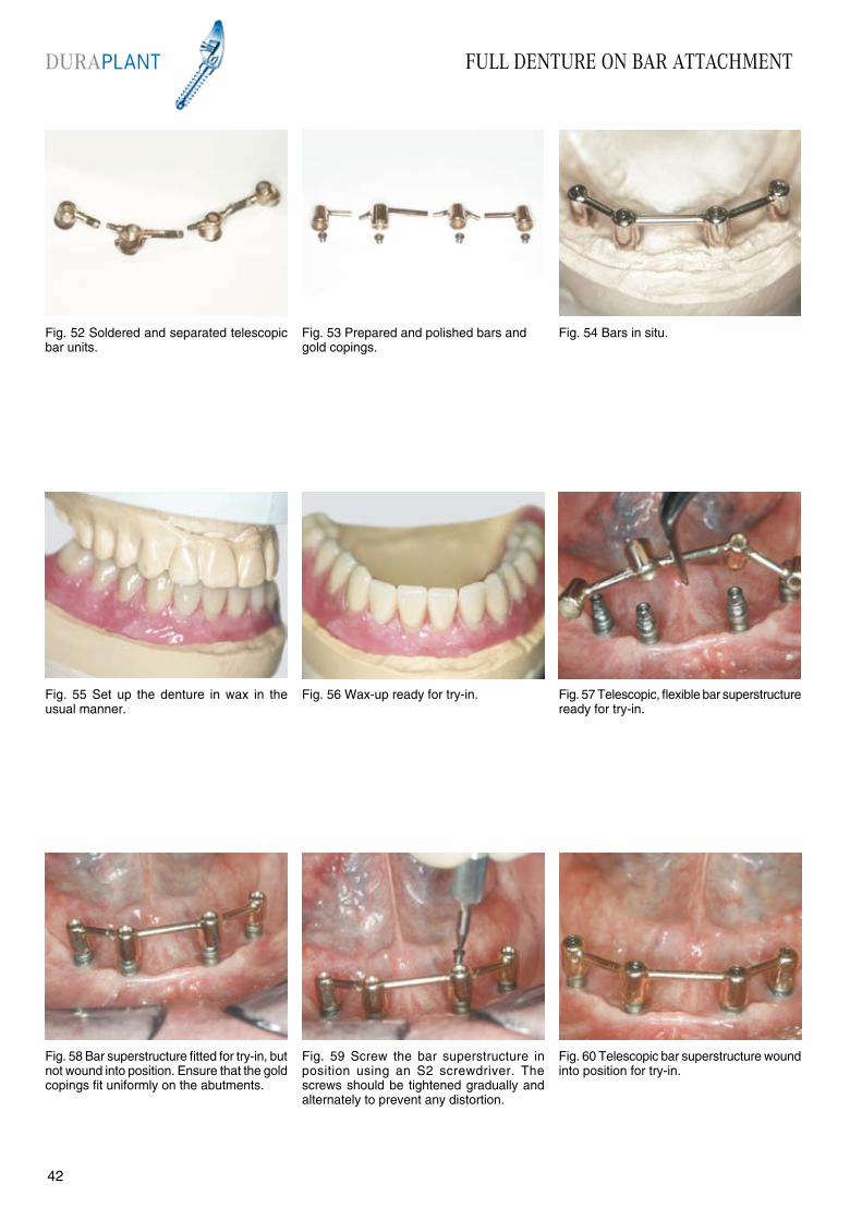
Fig. 58 Bar superstructure fitted for try-in, but not wound into position. Ensure that the gold copings fit uniformly on the abutments.
Fig. 55 Set up the denture in wax in the usual manner.
Fig. 57 Telescopic, flexible bar superstructure ready for try-in.
Fig. 59 Screw the bar superstructure in position using an S2 screwdriver. The screws should be tightened gradually and alternately to prevent any distortion.
Fig. 60 Telescopic bar superstructure wound into position for try-in.
Fig. 56 Wax-up ready for try-in.
Fig. 52 Soldered and separated telescopic bar units.
Fig. 54 Bars in situ.Fig. 53 Prepared and polished bars and gold copings.
DURAPLANT
4342
FULL DENTURE ON BAR ATTACHMENT
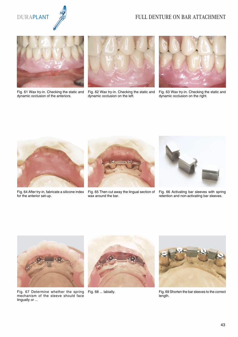
Fig. 61 Wax try-in. Checking the static and dynamic occlusion of the anteriors.
Fig. 62 Wax try-in. Checking the static and dynamic occlusion on the left.
Fig. 63 Wax try-in. Checking the static and dynamic occlusion on the right.
Fig. 64 After try-in, fabricate a silicone index for the anterior set-up.
Fig. 65 Then cut away the lingual section of wax around the bar.
Fig. 68 ... labially.Fig. 67 Determine whether the spring mechanism of the sleeve should face lingually or ...
Fig. 66 Activating bar sleeves with spring retention and non-activating bar sleeves.
Fig. 69 Shorten the bar sleeves to the correct length.
DURAPLANT
4342

FULL DENTURE ON BAR ATTACHMENT
Fig. 76 ... and the bar superstructure is fitted onto the abutments.
Fig. 73 Remove the lower denture carefully from the model. The resilience spacers must be removed from the bar sleeves..
Fig. 75 After finishing, the lumens of the bar superstructure are filled with No. 10550 TectuSil before the final fitting ...
Fig. 77 Tighten the screws gradually and alternately using an S2 screwdriver. The available working time (TectuSil) is 6 minutes.
Fig. 78 After the TectuSil has set, the superstructure should be very carefully cleaned to remove any residual luting material. Also probe the implant sulcus!
Fig. 74 Finished denture and bars.
Fig. 70 Sandblast the outer surfaces of the bar sleeves (250 µm) to provide additional retention in the acrylic. The inner surfaces should be coated in wax to protect them when sandblasting.
Fig. 72 Seal the lingual sections of the wax set-up and finish the denture in the usual manner.
Fig. 71 Block out the gold copings using plaster or silicone. Ensure that acrylic cannot flow into the screw of the activating sleeve.
DURAPLANT
4544

FULL DENTURE ON BAR ATTACHMENT
Fig. 79 Bar superstructure wound into position. Fig. 80 Check the denture base again before fitting.
Fig. 81 Denture in situ.
Fig. 82 Denture in occlusion.
Advantages:• Tried and tested restoration• Minimum resorption of the jaw distally due to “resilient bar movements”• Does not restrict the tongue space
Disadvantages:• Relatively difficult to clean for patients with poor dexterity
DURAPLANT
4544
Recall Page 46
RECALLDURAPLANT
4746
During the standard healing period there is up to three times more bone coverage (provided bone conditions are average) on a Ticer“ implant surface than on a titanium implant surface (KNÖFLER and GRAF 1988). There is also further bone coverage after this period.
Functional loading, which only occurs after implant recovery and is transmitted to the implant via the sulcus former, creates forces that further adapt the peri-implant bone. This results in additional (load-induced) remodelling of the bone with increased bone coverage.
In the first three months after fitting a superstructure with greater functional loading, this load-induced bone remodelling process intensifies and should therefore be monitored.
When monitoring this, also recheck the static and dynamic occlusion for any possible problems.
Repeated loosening of the screws at this stage clearly indicates stresses between the superstructure and implants. According to WEBER, BENZING and GEISS-GERSTORFER (1998) loading on the implant/bone interface resulting from loose-fitting superstructures is perhaps much greater than masticatory loading, even with superstructures which were clinically satisfactory at try-in.
Early signs of changes in the peri-implant conditions become apparent at a later stage.
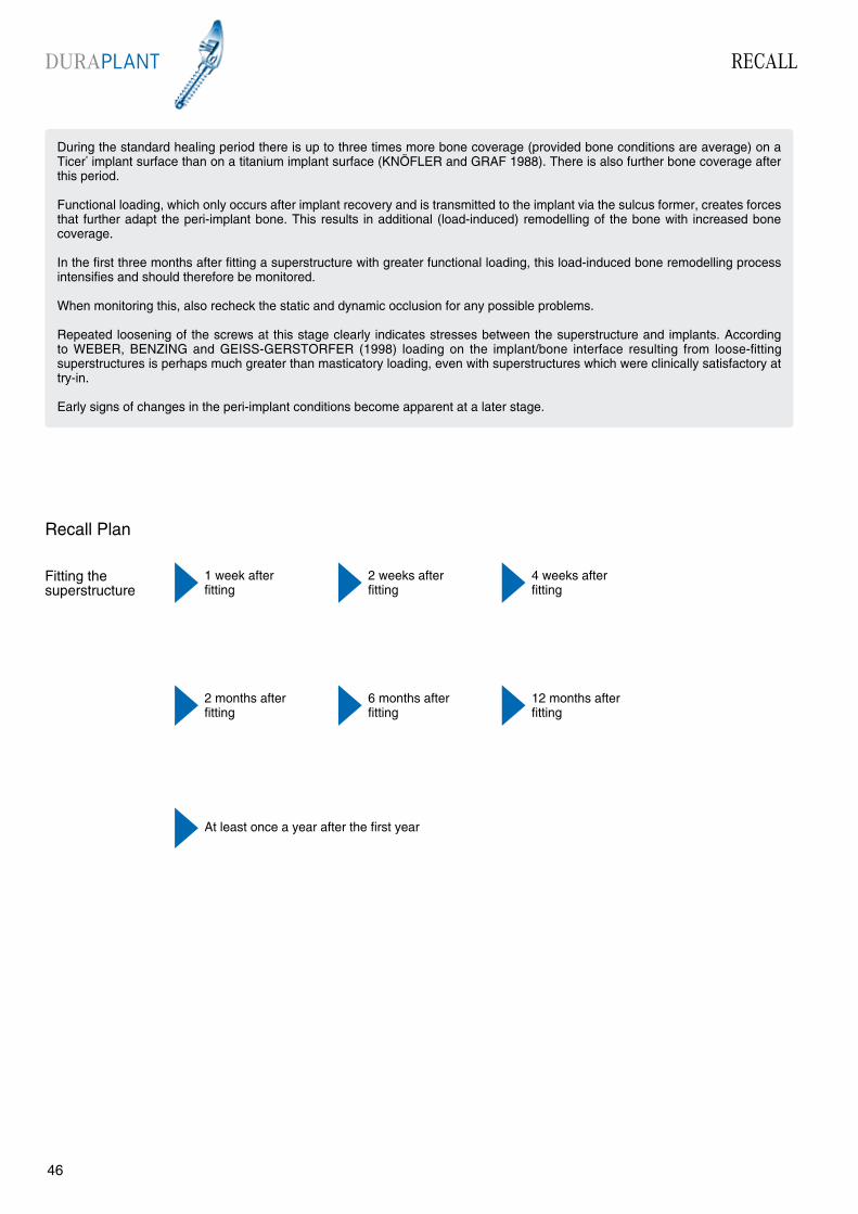
Fitting the superstructure
Recall Plan
2 weeks after fitting
4 weeks after fitting
1 week afterfitting
6 months after fitting
2 months after fitting
12 months after fitting
At least once a year after the first year

IMPLANT SYSTEM INSTRUCTIONS FOR USEDURAPLANT
4746
Manufacturer: ZL-MICRODENT-ATTACHMENT GMBH & Co. KGSchützenstraße 6-8, 58339 BreckerfeldTel.: 02338-8010 Fax: 02338-80140
1. General InformationDURAPLANT implants should only be used by appropriately qualified dentists and doctors and superstructures should only be fabricated by trained dentists and dental technicians. The following instructions for use are not sufficiently comprehensive to allow immediate use of the implant system. We strongly recommend that an experienced colleague provides instruction and supervision on the use of the implant system.
2. Description of DURAPLANT implants Screw implants fabricated from TIMEDUR® cold-hardened pure titanium with a TICER® surface in diameters of 2.9, 3.2, 3.5, 3.8 and 4.1 mm and in lengths of 9, 12 and 15 mm. As DURAPLANT implants form part of a whole concept, only original components and instruments should be used in accordance with the instructions and recommen-dations of the manufacturer. The manufacturer accepts no responsibility if components from other manufacturers are used.
2.1 Materials Implants: TIMEDUR® pure titanium TICER® surface Healing caps and secondary units: TIMEDUR® pure titanium Instrumentarium: TIMEDUR® pure titanium, stainless steel, all components can be sterilized in an autoclave Prosthetic primary units: TIMEDUR® pure titanium
Prosthetic secondary units: TIMEDUR® pure titanium, Au-Pt alloy or POM (plastic)
3. IndicationsDURAPLANT implants cover all indications for endosteal implants in the upper and lower jaw with the exception of immediate loading implants. The implants can therefore be used in the rehabilitation of an edentulous jaw or a partially edentulous jaw. Crowns, bridges and dentures can be used as prosthetic restorations.
3.1. ContraindicationsConditions or illnesses that make surgery seem unjustifiable affect normal wound healing
cause problems with normal functioning of the immune system preclude normal reactivity of the bone.
NOTE: Periodontal disease should be controlled by hygiene and/or surgical measures before implant treatment. Poor oral hygiene and lack of cooperation by the patient are further contra-indications.
The implants must not be contaminated in any way and should be kept in the sterile pack until immediately before insertion. If handling the implant is unavoidable, the titanium tweezers supplied should always be used.
NOTE: The ratchet should be dismantled immedi-ately after use and the individual units thoroughly cleaned and disinfected.
8. Packaging and sterilityThe DURAPLANT implant packaging compri-ses: non-sterile storage packaging with instruc- tions for use and separate adhesive labels for the patient ID card and patient file
secondary packaging as a germ barrier (glass bottle with screw seal) sterile primary packaging (glass bottle with silicone seal and placement aid for the sterile implant)
A DURAPLANT implant that has been used, is non-sterile or contaminated, should never be implanted. Important: If the original packaging is damaged, the implant cannot be returned to the manufacturer.
9. SterilizationDURAPLANT implants are sterilized by gamma radiation.
10. ResterilizationDURAPLANT implants should never be re-sterilized. The manufacturer accepts no re-sponsibility if the implant has been resterilized.
11. StorageDURAPLANT implants should be stored in their original packaging in a dry place at normal room temperature. The implants should not be used after the sterilization expiry date.
12. Traceability and documentation Implants can be traced using the order and batch numbers. It is possible to trace the implants from the patient to the manufacturer by means of the adhesive labels on the patient ID card and patient file. For forensic reasons the manufacturer recom-mends full clinical, radiological, photographic and statistical documentation.
13. Sale of DURAPLANT implantsDURAPLANT implants are for sale exclusively to doctors and dentists. We strongly recommend attending a manufacturer’s training course.
4. Side effects and interactionsExtreme physical loading should be avoided postoperatively. Titanium implants have no known side effects.Possible complications: damage to anatomical structures (permanent anaesthesia caused by damage to the inferior alveolar nerve, perforation of the nasal cavity or maxillary sinus) chronic pain related to the implant
fractures: bone fracture, implant or instrument fracture, fracture of the restoration periimplant inflammation
NOTE: If unexpected pain or complications occur, the doctor or dentist responsible for treatment should be consulted immediately. It is a known fact that implants sometimes do not heal and fail without any apparent cause.
5. Preoperative planningGeneral medical examination; full clinical and radiological dental examination; informing the patient about indications, contraindications and success rates; informing the patient about the need for regular checkups, including setting up an oral hygiene regime, involving sanitation by periodontal surgery if necessary; establishing an overall preoperative and prosthetic plan in consultation with the dental technician.
6. Surgical techniqueDURAPLANT training covers instruction in the surgical technique used with the system. A skilful operating technique in the hard and soft tissue is essential to create optimum conditions for implant healing.
NOTE: The drill should be 1 mm longer than the insertion depth of the implants.
The following measures are necessary to pre-vent any thermal preparation trauma: low motor speed of 500 to 800 rpm use of sharp drills use of DURAPLANT drills in ascending order of diameter size internal and/or external cooling of the drills with sterilized sodium chloride solution implants with a diameter of 3.8 mm or 4.1 mm should never be used as self-tapping implants
The standard healing period is 3 months in the lower jaw and 6 months in the upper jaw. Implants should not be loaded prosthetically until after these healing periods.
7. General handlingAll instruments should be thoroughly cleaned, disinfected and sterilized before use. General rules of hygiene for surgical operations should be followed before each operation to reduce germs to an absolute minimum.
ZL MICRODENTAttachment GmbH & Co. KGSchützenstraße 6 - 8D 58339 Breckerfeld
Tel. +49 2338 801-0Fax. +49 2338 [email protected]
Dr.N
r.: V
A. D
URA
. EN
. 01
. 07
Precision since 1968
Instructions for use No. 5 ANCHOR-SYSTEM
Precision since 1968
Instructions for use No. 5
ANCHOR-SYSTEM
Instructions for use No. 4 ROBOLOCK
Precision since 1968
Instructions for use No. 4
ROBOLOCK
Precision since 1968
Instructions for use No. 3
CENTRALOCK II
Instructions for use No. 3 CENTRALOCK
Instructions for use No. 2VENTRALOCK
Precision since 1968
Instructions for use No. 2
VENTRALOCKPRODUCT OVERVIEW
ATTACHMENTS
Product Overview ATTACHMENTS
Precision since 1968
Instructions for use No. 1
Instructions for use No. 1 DUOLOCK / LOGA®
DUOLOCK
LOGA®


![INDEX [microdentsystem.com] · INTRODUCTION REMOVABLE AND IMMEDIATE . PROSTHESIS MULTIPLE PROSTHESIS. CEMENTED PROSTHESIS. Microdent Genius conical (straight) abutment or Microdent](https://img.pdfslide.net/doc/110x75/5facd9ef77a5ed547a36b19e/index-introduction-removable-and-immediate-prosthesis-multiple-prosthesis.jpg)