Embed Size (px)
Citation preview

Vacuum gaugeDVR 2pro
Instructions for useOriginal instructions_EN N°: 20901502
Technology for Vacuum Systems

Imprint
2 20901502_EN_DVR 2pro_V1.4_060420
Original instructionsKeep for further use!This manual is only to be used and distributed in its complete and original form. It is strictly the users’ responsibility to check carefully the validity of this manual with respect to his product.
Manufacturer:VACUUBRAND GMBH + CO KGAlfred‑Zippe‑Str. 497877 WertheimGERMANY
Phone: � Head office +49 9342 808‑0 � Sales +49 9342 808‑5550 � Service +49 9342 808‑5660
Fax: +49 9342 808‑5555E‑Mail: [email protected]: www.vacuubrand.com
Thank you for purchasing this product from VACUUBRAND GMBH + CO KG . You have chosen a modern and technically high quality product.

Content
320901502_EN_DVR 2pro_V1.4_060420
TABLE OF CONTENT
What’s in the box 4
1 Introduction 51.1 User information . . . . . . . . . . . . . . . . . . . . . . . . . . . . . . . . . 51.2 About this document. . . . . . . . . . . . . . . . . . . . . . . . . . . . . . 6
1.2.1 Display conventions . . . . . . . . . . . . . . . . . . . . . . . . . . 61.2.2 Symbols and icons . . . . . . . . . . . . . . . . . . . . . . . . . . . 71.2.3 Handling instructions (action steps). . . . . . . . . . . . . . . 81.2.4 Abbreviations . . . . . . . . . . . . . . . . . . . . . . . . . . . . . . . 91.2.5 Term definition . . . . . . . . . . . . . . . . . . . . . . . . . . . . . . 9
2 Safety instructions 102.1 Usage . . . . . . . . . . . . . . . . . . . . . . . . . . . . . . . . . . . . . . . . 10
2.1.1 Intended use . . . . . . . . . . . . . . . . . . . . . . . . . . . . . . . 102.1.2 Improper use. . . . . . . . . . . . . . . . . . . . . . . . . . . . . . . 102.1.3 Foreseeable misuse . . . . . . . . . . . . . . . . . . . . . . . . . 11
2.2 General safety instructions. . . . . . . . . . . . . . . . . . . . . . . . 122.2.1 Safety precautions . . . . . . . . . . . . . . . . . . . . . . . . . . 122.2.2 Personnel . . . . . . . . . . . . . . . . . . . . . . . . . . . . . . . . . 12
2.3 Correct battery handling . . . . . . . . . . . . . . . . . . . . . . . . . . 132.4 Proper disposal . . . . . . . . . . . . . . . . . . . . . . . . . . . . . . . . 13
3 Product description 143.1 Vacuum gauge DVR 2pro. . . . . . . . . . . . . . . . . . . . . . . . . 15
3.1.1 Various views . . . . . . . . . . . . . . . . . . . . . . . . . . . . . . 153.1.2 Support rod. . . . . . . . . . . . . . . . . . . . . . . . . . . . . . . . 17
3.2 Application example . . . . . . . . . . . . . . . . . . . . . . . . . . . . . 18
4 Assembly and connection 194.1 Installation conditions . . . . . . . . . . . . . . . . . . . . . . . . . . . . 194.2 Insert (replace) battery . . . . . . . . . . . . . . . . . . . . . . . . . . . 204.3 Install adjustable support . . . . . . . . . . . . . . . . . . . . . . . . . 214.4 Vacuum connection . . . . . . . . . . . . . . . . . . . . . . . . . . . . . 22
5 Operation 255.1 Operating and display elements . . . . . . . . . . . . . . . . . . . . 25
5.1.1 Operating elements . . . . . . . . . . . . . . . . . . . . . . . . . 255.1.2 Key combinations . . . . . . . . . . . . . . . . . . . . . . . . . . . 265.1.3 Automatic jump‑back times. . . . . . . . . . . . . . . . . . . . 265.1.4 Display elements. . . . . . . . . . . . . . . . . . . . . . . . . . . . 275.1.5 Display icons. . . . . . . . . . . . . . . . . . . . . . . . . . . . . . . 28

Content
4 20901502_EN_DVR 2pro_V1.4_060420
5.2 DVR 2pro handling . . . . . . . . . . . . . . . . . . . . . . . . . . . . . . 295.2.1 Select pressure unit . . . . . . . . . . . . . . . . . . . . . . . . . 295.2.2 Adjust switch on time and measuring cycle . . . . . . . 305.2.3 Pressure measurement. . . . . . . . . . . . . . . . . . . . . . . 32
6 Cleaning and adjustment 336.1 Cleaning . . . . . . . . . . . . . . . . . . . . . . . . . . . . . . . . . . . . . . 33
6.1.1 Housing surface . . . . . . . . . . . . . . . . . . . . . . . . . . . . 336.1.2 Sensor . . . . . . . . . . . . . . . . . . . . . . . . . . . . . . . . . . . 33
6.2 Sensor adjustment, in general . . . . . . . . . . . . . . . . . . . . . 346.2.1 Adjustment at atmospheric pressure. . . . . . . . . . . . . 346.2.2 Adjustment to reference pressure . . . . . . . . . . . . . . . 366.2.3 Adjustment under vacuum . . . . . . . . . . . . . . . . . . . . 38
7 Resolving problems 407.1 Error display . . . . . . . . . . . . . . . . . . . . . . . . . . . . . . . . . . . 407.2 Fault – Cause – Remedy . . . . . . . . . . . . . . . . . . . . . . . . . 41
8 Appendix 428.1 Technical information . . . . . . . . . . . . . . . . . . . . . . . . . . . . 42
8.1.1 Technical data. . . . . . . . . . . . . . . . . . . . . . . . . . . . . . 428.1.2 Wetted materials . . . . . . . . . . . . . . . . . . . . . . . . . . . . 438.1.3 Device data. . . . . . . . . . . . . . . . . . . . . . . . . . . . . . . . 44
8.2 Ordering information. . . . . . . . . . . . . . . . . . . . . . . . . . . . . 458.3 Service . . . . . . . . . . . . . . . . . . . . . . . . . . . . . . . . . . . . . . . 468.4 Index. . . . . . . . . . . . . . . . . . . . . . . . . . . . . . . . . . . . . . . . . 478.5 EC Declaration of Conformity . . . . . . . . . . . . . . . . . . . . . . 488.6 Declaration of Conformity – China RoHS 2 . . . . . . . . . . . 50
What’s in the boxWhat’s in the box
520901502_EN_DVR 2pro_V1.4_060420
Introduction
1 1 IntroductionIntroduction
This manual is part of your product.
1.1 1.1 User informationUser informationSafety
� Read this manual thoroughly and completely before using the produkt.
� Keep this manual in an easily accessible location. � Proper use of the product is essential for safe operation. Comply with all safety instructions provided!
� In addition to this manual, adhere to any relevant local accident prevention regulations and comply with industrial safety regula‑tions.
General
� Instead of the term DVR 2proDVR 2pro mostly the term Gauge Gauge or Vacuum Vacuum gaugegauge is used in this manual, in order to make the text more readable.
� The illustrations in this manual are provided as examples in order for a better understanding.
� They are intended to aid in your understanding of the proper use of the product.
Contact
� Please ask for replacement in case of an incomplete manual or download the manual on our website: www.vacuubrand.com
� Contact us regarding any questions about this product, if you need further information, or to provide us with feedback.
� When contacting our Customer Service Department, please be sure to have the correct type and serial number of your product at call device data on the product, see chapter 8.1.3 Device data on page 448.1.3 Device data on page 44
General information
Instructions for use and safety
Contact us

6 20901502_EN_DVR 2pro_V1.4_060420
Introduction
CopyrightThe content of this manual is protected by copyright. Only copies for internal use are allowed, e. g., for professional training.© VACUUBRAND GMBH + CO KG
1.2 1.2 About this documentAbout this document1.2.1 1.2.1 Display conventionsDisplay conventions
Warning levels
WARNINGIndicates a potentially hazardous situation.
Disregarding the situation could result in serious, even fatal injury or massive damage to property.> Take appropriate action to avoid dangerous situation!
CAUTIONIndicates a potentially hazardous situation.
Disregarding the situation could result in slight or minor injury or damage to property.> Take appropriate action to avoid dangerous situation!
NOTICENOTICENotice for a potentially harmful situation.Disregarding the notice could lead to material damage.
Additional notes
> Information or specific use recommendation, which must be observed. > Important information for proper operation.
> Helpful tips and tricks> Additional information
IMPORTANT!
Copyright ©
Warning levels

720901502_EN_DVR 2pro_V1.4_060420
Introduction
1.2.2 1.2.2 Symbols and Symbols and iconsicons
This manual includes symbols and icons. Safety symbols indicate special danger in handling the product. Icons shall help to identify the danger directly and easier.
Safety symbols
General warning symbol. danger: electricity
General prohibition symbol.
General mandatory sign.
Additional icons
positive example – Do!result – o. k.
negative example – Do not!
Refers to content in this manual.
Refers to content of other supplementary doc‑uments.
Electric/electronic devices and batteries must not be disposed of in the domestic waste at the end of their service life.
Press key. Push and hold key
Continous signal Flashing cycle
> For further detailed information about icons and signals in the display see chapter Display icons on page 28Display icons on page 28.
Notes
Handling or action
Signals

8 20901502_EN_DVR 2pro_V1.4_060420
Introduction
1.2.3 1.2.3 Handling instructions (action steps)Handling instructions (action steps)
Action step (single step) > Do the described step.
5 Result of action
Handling instructions (multiple steps)
1. first step2. next step
5 Result of action
Follow steps in the described order.
Presentation convention operating
steps

920901502_EN_DVR 2pro_V1.4_060420
Introduction
1.2.4 1.2.4 AbbreviationsAbbreviations
abs. absoluteATM Atmospheric pressuredi (di) Interior diameterDAkkS accreditation institute:
Deutsche Akkreditierungsstelle GmbHDN Nominal diameterGF Glass fiber reinforcedGK Glass pelletsGr. SizehPa Pressure unit, Hectopascal (1 hPa = 1 mbar =
0.75 Torr)KF Small flangemax Maximum valuembar Pressure unit, millibar (1 mbar = 1 hPa = 0.75 Torr)min Minimum valuePA PolyamidePBT Polybutylene terephthalatePP PolypropylenePPS Polyphenylene sulphidePTFE PolytetrafluorethyleneRMA‑N° Return Merchandise Authorization numberSec. Second(s)Torr Pressure unit (1 Torr = 1.33 mbar = 1.33 hPa)
1.2.5 1.2.5 Term definitionTerm definition
DVR 2pro Fully electronic vacuum gauge for measurement within the measuring range of atmospheric pres‑sure and 1 mbar, with digital and analogue pres‑sure reading.
DVR 3pro Functions like DVR 2pro, including ATEX approvalRough vacuum Pressure measuring range in vacuum technology,
from: atmospheric pressure–1 mbar (atmospheric pressure–0.75 Torr)
Used Abbreviations
Product specific terms

10 20901502_EN_DVR 2pro_V1.4_060420
Safety instructions
2 2 Safety instructionsSafety instructions
The complete information of this chapter must be observed by all persons working with the herein described product. The safety instructions are valid for the complete life cycle of the product.
2.1 2.1 UsageUsageUse the product only when it is in proper working condition.
2.1.1 2.1.1 Intended useIntended use
A vacuum gauge DVR 2pro is a laboratory instrument for the measurement of absolute pressure in the range of rough vacuum and intended for connection to a vacuum apparatus. The gauge may only be installed and used in non‑explosive areas. The gauge is intended for continuous operation.Any other use is considered to be improper use.
Intended use also includes the following:
� observing safety information of document Safety Information for Vacuum Equipment.
� observing the safety information inside this manual
2.1.2 2.1.2 Improper useImproper use
Incorrect use or any application which does not correspond to the technical data may result in injury or damage to the property.
Improper use includes: � Using the product contrary to its intended use. � Operation despite obvious malfunctions or damages.
Intended use
Improper use

1120901502_EN_DVR 2pro_V1.4_060420
Safety instructions
� Operation at inadmissible operating conditions. � inadmissible modifications or repairs by customer.
The penetration of foreign objects, hot gases and flames from the application, must be excluded.
2.1.3 2.1.3 Foreseeable misuseForeseeable misuse
� The measuring of media which are liquid, hot, instable or explo‑sive.
� Installation and operation in explosive environments, � to switch the gauge on/off with tools, � to use a tool for battery replacement, which could cause a short circuit,
� to expose the gauge completely to vacuum, � to operate the controller with sharp stylus or objects. � to immerse the gauge into liquid or to clean it with steam.
Foreseeable misuse
Improper use
IMPORTANT!

12 20901502_EN_DVR 2pro_V1.4_060420
Safety instructions
IMPORTANT!
2.2 2.2 General safety instructionsGeneral safety instructions2.2.1 2.2.1 Safety precautionsSafety precautions
> Use the gauge only if you have understood its function and this manual. > Please note that adhering process media can pose danger to humans and the environment. > When handling with contaminated parts, follow the relevant regulations and safety precautions. > Repairs are only allowed by the Service Department or your local supplier.
For all service works hazardous substances need to be excluded.
> Fill in the form Health and Safety Clearance thoroughly and completely and confirm with your signature.
2.2.2 2.2.2 PersonnelPersonnel
It is the owner's responsibility to observe the proper use of the device.
> Always be conscious of safety, and work in a safe manner. > Observe the owners‘ directives at work, the national accident prevention regulations and occupational safety provisions.
IMPORTANT!
Safety precautions

1320901502_EN_DVR 2pro_V1.4_060420
Safety instructions
2.3 2.3 Correct battery handlingCorrect battery handling
CAUTIONRisk of personal injury or damage to property if batteries are used improperly.> Do not short‑circuit the battery or touch both poles at the same time.> Never charge the battery (= non‑rechargeable).> Never use damaged batteries.> Do not expose the battery to high temperatures.> If the battery leaks and you come into contact with the leaked fluids, rinse thoroughly with water and seek medical attention immediately!
2.4 2.4 Proper disposalProper disposal
NOTENOTEElectronic components and batteries must not be disposed of in the domestic waste at the end of their service life.Used electronic devices and batteries contain harmful subs‑tances that can cause damage to the environment or human health. Disused electrical devices also contain valuable raw materials, which can be recovered for reuse if the device is dis‑posed of correctly within the recycling process.End users are legally obliged to take used electric and elect‑ronic devices to a licensed collection point and to return spent batteries.> It is your responsibility to save and delete any data before disposing of your electronic device.> If the device contains batteries: Remove spent batteries before disposal.Correctly dispose of all electronic scrap and electric components at the end of their service life.> Observe the national regulations regarding disposal and environmental protection.
Correct battery handling

14 20901502_EN_DVR 2pro_V1.4_060420
Product description
3 3 Product descriptionProduct description
Goods arrivalCheck the shipment for transport damage and completeness.
> Report any transit damage immediately to the supplier.
NOTICENOTICECondensate could damage the gauge.A large difference in temperature between storage location and installation location can cause condensation.> Let the product acclimatise for 3‑4 hours before using it.
Included materials
GaugeDVR 2pro 20682906Support rod 20682839Knurled nut M14x1 (union nut) 20637657Hose nozzle DN 6/10 20636635Locking ring for knurled nut 20637658Small flange KF 16 PPProtective cap DN 10/16O‑ring
20635110
9 V Block‑type battery, enclosed 20612891Instructions for use 20901502Safety Information for Vacuum Equipment 20999254Original packaging ‑‑‑‑‑‑
Goods arrival
Included materials
1520901502_EN_DVR 2pro_V1.4_060420
Product description
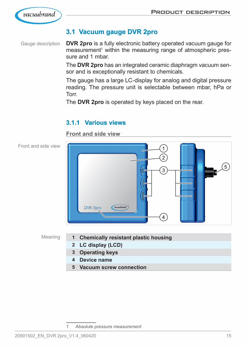
3.1 3.1 Vacuum gauge DVR 2proVacuum gauge DVR 2proDVR 2pro is a fully electronic battery operated vacuum gauge for measurement1 within the measuring range of atmospheric pres‑sure and 1 mbar.The DVR 2pro has an integrated ceramic diaphragm vacuum sen‑sor and is exceptionally resistant to chemicals.The gauge has a large LC‑display for analog and digital pressure reading. The pressure unit is selectable between mbar, hPa or Torr.The DVR 2pro is operated by keys placed on the rear.
3.1.1 3.1.1 Various viewsVarious views
Front and side view
5
1
2
3
4
1 Chemically resistant plastic housing2 LC display (LCD)3 Operating keys4 Device name5 Vacuum screw connection
1 Absolute pressure measurement
Gauge description
Front and side view
Meaning

16 20901502_EN_DVR 2pro_V1.4_060420
Product description
Rear view
Rear side
9
8
5
7
6
3
3 Operating keys5 Vacuum screw connection, support for
` Hose nozzle with locking ring and knurled nut or
` Hose directly connected with locking ring and knurled nut or
` Small flange KF 166 Serial number + CE symbol7 Blind hole with thread M8 for support rod8 Manufacturer + address (rating plate)9 Battery compartment lid with screw (captive screw)
` Block‑type battery 9 V
Meaning
1720901502_EN_DVR 2pro_V1.4_060420
Product description
Side view
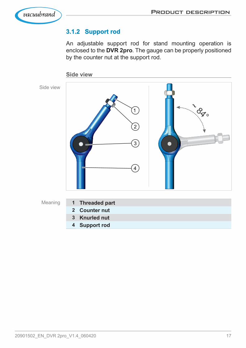
3.1.2 3.1.2 Support rodSupport rod
An adjustable support rod for stand mounting operation is enclosed to the DVR 2pro. The gauge can be properly positioned by the counter nut at the support rod.
Side view
4
2
1
3
1 Threaded part2 Counter nut3 Knurled nut4 Support rod
Meaning

18 20901502_EN_DVR 2pro_V1.4_060420
Product description
3.2 3.2 Application exampleApplication example
2
4
1
3
6
5
1 DVR 2pro with support rod2 Support rod3 Applications4 Diaphragm pump, vacuum pump5 Vacuum hose6 Vacuum splitter, e. g., VACUU·LAN®
Please observe the following points to get an optimal measuring result:> Connect the gauge as close as possible to the apparatus, not to the vacuum pump.> If possible use the small flange for connection.> Connect the vacuum line as short as possible with a cross‑section as wide as possible.
ExampleDVR 2pro and
filtration
Meaning

1920901502_EN_DVR 2pro_V1.4_060420
Assembly and connection
4 4 Assembly and connectionAssembly and connection
The gauge is provided to be used directly at the application.
> Observe all specifications for installation, connection and operation according to technical data, see chapter Technical information on page 42Technical information on page 42. > Also observe rating plate data. > Compare the permitted limits which are described in this manual, with your actual application regarding operating media, pressures, forces, moments, temperatures and volt‑age.
NOTICENOTICEPermanent vibrations which are transmitted from the apparatus to the gauge could loosen screw connections.> Mount the gauge to a vibration‑free apparatus.> Please use buffers, if constant vibration is unavoidable.
4.1 4.1 Installation conditionsInstallation conditions
Consider installation conditions
� The gauge has acclimatized.
� Ambient conditions are observed and are within the limitation of use.
Limitation of use (US)Ambient temperature 10–40 °C 50–104 °FAltitude, max. 3000 m
über NHN9840 ftabove sea level
Relative humidity 30–85 %, non condensingProtection type IP 40Avoid condensation or contamination by dust or liquids.
Limitation of use

20 20901502_EN_DVR 2pro_V1.4_060420
Assembly and connection
4.2 4.2 Insert (Insert (replace) batteryreplace) batteryThe battery is enclosed to the delivery and must be inserted into the gauge before installation.
Insert (replace)1 batteryRequired tool Phillips screwdriver size 1.
1. Use a Phillips screwdriver to unscrew the screw of the battery compartment lid.
2. Remove battery compartment lid with captive screw. If changing the battery, please remove the discharged battery.IMPORTANT! Tools for battery replacement must not cause
a short‑circuit.
3. Put in the new battery in correct position (compare to figure inside the housing).
4. Put the battery compartment lid in correct position onto the gauge and fix it stress‑free by the captive screw. When tight‑ening, observe the maximum torque of 0.4 Nm.
1 approved batteries see chapter: 8.2 Ordering information on page 458.2 Ordering information on page 45
Insert battery
2120901502_EN_DVR 2pro_V1.4_060420
Assembly and connection
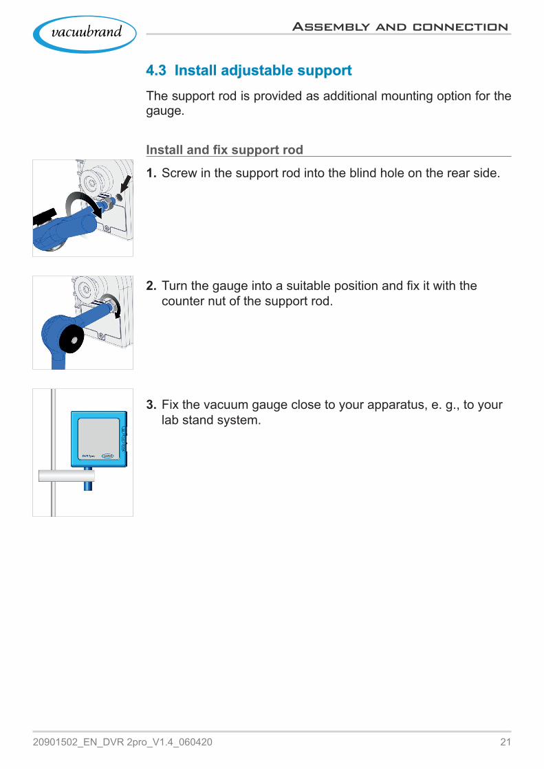
4.3 4.3 Install adjustable supportInstall adjustable supportThe support rod is provided as additional mounting option for the gauge.
Install and fix support rod
1. Screw in the support rod into the blind hole on the rear side.
2. Turn the gauge into a suitable position and fix it with the counter nut of the support rod.
3. Fix the vacuum gauge close to your apparatus, e. g., to your lab stand system.

22 20901502_EN_DVR 2pro_V1.4_060420
Assembly and connection
4.4 4.4 Vacuum connectionVacuum connection
WARNINGRisk of bursting> Prevent uncontrolled overpressure, e. g., when connecting to a locked or blocked tubing system.
> Maximum admissable pressure at vacuum sensor: 1,5 bar/1126 Torr (abs.). > Pollution and damages, especially at the flange, could affect the measurement.
Connection options
Connection via PTFE hose DN 8/10or
Connection via hose nozzle DN 6/10or
Connection via small flange KF DN16
Connection via hose nozzleRequired connection material: Hose nozzle DN 6/10 mm, kurled nut M14x1, locking ring; optionally: Vacuum hose and compatible hose clamp (tool: fork wrench size 17).
1. If installed, unscrew the small flange from the vacuum con‑nection of the gauge.
2. Connect hose nozzle (a), kurled nut (b) and locking ring (c) as shown in the figure.
(c)(a) (b)
IMPORTANT!

2320901502_EN_DVR 2pro_V1.4_060420
Assembly and connection
(e)(d)
3. Push the PTFE‑hose into the vacuum connection connection of the gauge and fasten it with the kurled nut.
4. Push the vacuum hose (d) of the apparatus onto the hose nozzle and fasten the hose, e. g., with a hose clamp (e).
5. Fix the vacuum gauge close to your apparatus, e. g., by using the support rod.
Connection via PTFE hoseRequired connection material: Kurled nut M14x1, locking ring; optionally: PTFE Hose DN 8/10.
1. If installed, unscrew the small flange from the vacuum con‑nection of the gauge.
2. Connect locking ring (b), kurled nut (c) and PTFE hose (f) as shown in the figure.
3. Push the PTFE‑hose into the vacuum connection connection of the gauge and fasten it with the kurled nut.
5 PTFE Hose fixed.
> Use a stable vacuum hose that is suitable for the required vacuum range. > Connect hose tubes as short as possible.
IMPORTANT!
(c)(f) (b)

24 20901502_EN_DVR 2pro_V1.4_060420
Assembly and connection
Connection via small flangeRequired connection material: Clamping ring with centering or centering ring for KF DN16 (tool: fork wrenche size 17).
1. Place the small flange KF DN16 on top of vacuum connection of the gauge.
2. Screw in the small flange KF DN16 hand tight.
3. Remove the protection cap (g) from the small flange KF DN16 (h).
4. Put the gauge with the centering onto the connection of the apparatus small flange KF DN16.
5. Fix the vacuum gauge with a clamping ring (i).
i
(g)HH
2520901502_EN_DVR 2pro_V1.4_060420
Operation
5 5 OperationOperation
5.1 5.1 Operating and display elementsOperating and display elements5.1.1 5.1.1 Operating elementsOperating elements
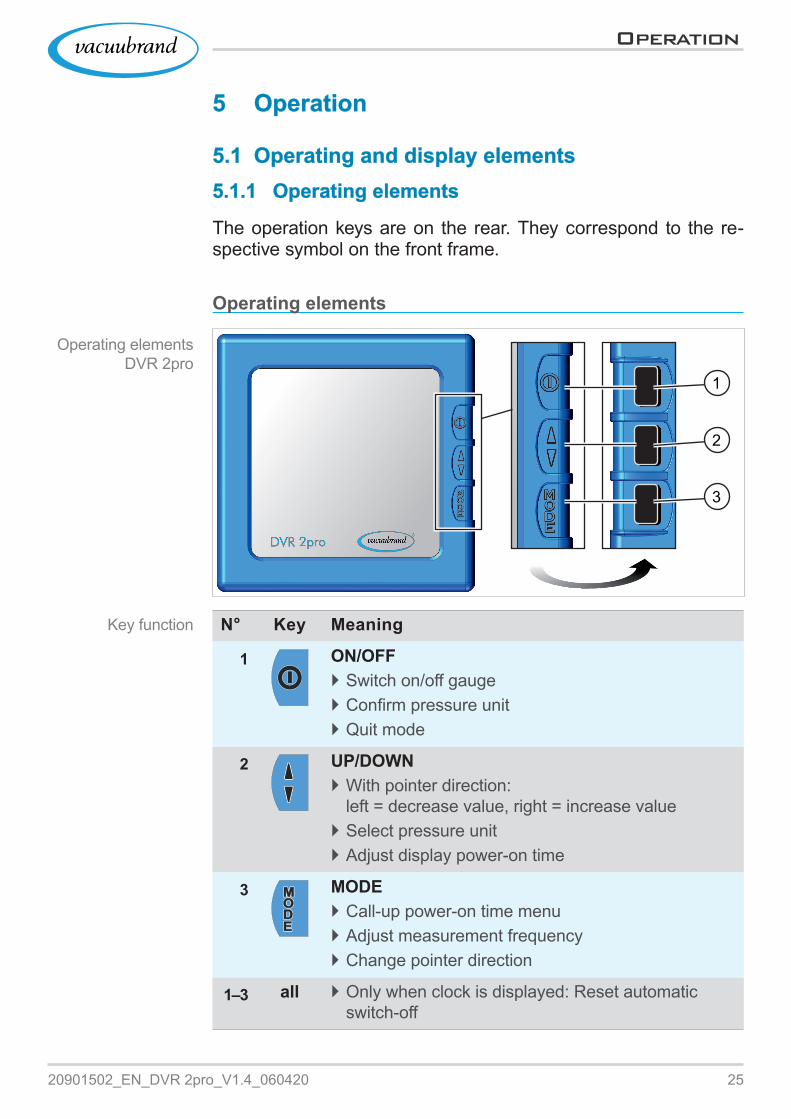
The operation keys are on the rear. They correspond to the re‑spective symbol on the front frame.
Operating elements
1
2
3
N° Key Meaning
1 ON/OFF ` Switch on/off gauge ` Confirm pressure unit ` Quit mode
2 UP/DOWN ` With pointer direction: left = decrease value, right = increase value
` Select pressure unit ` Adjust display power‑on time
3 MODE ` Call‑up power‑on time menu ` Adjust measurement frequency ` Change pointer direction
1–3 all ` Only when clock is displayed: Reset automatic switch‑off
Operating elements DVR 2pro
Key function
26 20901502_EN_DVR 2pro_V1.4_060420
Operation
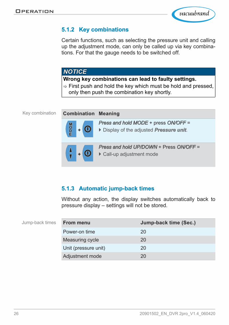
5.1.2 5.1.2 Key combinationsKey combinations
Certain functions, such as selecting the pressure unit and calling up the adjustment mode, can only be called up via key combina‑tions. For that the gauge needs to be switched off.
NOTICENOTICEWrong key combinations can lead to faulty settings.> First push and hold the key which must be hold and pressed, only then push the combination key shortly.
Combination Meaning
+ Press and hold MODEPress and hold MODE + press ON/OFFON/OFF = ` Display of the adjusted Pressure unitPressure unit.
+ Press and hold UP/DOWNPress and hold UP/DOWN + Press ON/OFFON/OFF = ` Call‑up adjustment mode
5.1.3 5.1.3 Automatic jump‑back timesAutomatic jump‑back times
Without any action, the display switches automatically back to pressure display – settings will not be stored.
From menu Jump‑back time (Sec.)
Power‑on time 20Measuring cycle 20Unit (pressure unit) 20Adjustment mode 20
Key combination
Jump‑back times

2720901502_EN_DVR 2pro_V1.4_060420
Operation
5.1.4 5.1.4 Display elementsDisplay elements
Directly after switching on the pressure reading will be displayed.
Display with pressure reading and icons
5
4
1
3
2
1 Display icons2 Pointer (clock‑hand)3 Analog pressure reading, display scale with current pressure4 Digital pressure reading, current pressure as numeral value5 Pressure unit referring to pre‑setting (mbar, Torr, hPa)
Display elements DVR 2pro

28 20901502_EN_DVR 2pro_V1.4_060420
Operation
5.1.5 5.1.5 Display iconsDisplay icons
With switched‑on gauge additional symbols appear on the display, depending on state.
Meaning of display icons
Icon Meaning
Warning triangle ` Warning ` Adjustment mode active
Clock ` Automatic switch‑off activated ` The display of the gauge swichtes off after approx. 30 Seconds > to stop switch‑off press any key shortly
Battery ` Battery low ` Battery replacement required
Pointer ` Display measurement value ` Display pointer direction (left/right)
` C A C A = automatic adaption of the measuring cycle; more frequent readings for large pressure vari‑ation
Pointer – Adjust measuring cycle
` C 1 C 1 = 1x measuring per 3 Seconds = blinking cycle 3 Sec.
` C 2 C 2 = 1x measuring per 1 Second = blinking cycle 1 Sec.
` C 3 C 3 = 3x measuring per 1 Second = blinking cycle 0.3 Sec.
Display icons DVR 2pro

2920901502_EN_DVR 2pro_V1.4_060420
Operation
5.2 5.2 DVR 2pro handlingDVR 2pro handling5.2.1 5.2.1 Select pressure unitSelect pressure unit
Set pressure unit
+1. Press and hold the MODEMODE key at the switched‑off gauge and
then press ON/OFFON/OFF key.
5 Displays the selected pressure unit, e. g., hPa.
2. Press key UP/DOWNUP/DOWN as often as the required pressure unit is displayed.
� Switchable: mbar, Torr, hPa
5 Displays the selected pressure unit, e. g., mbar.
3. Press key ON/OFFON/OFF to confirm the selection.
5 Switch to pressure reading. 5 Pressure unit adjusted on mbar .

30 20901502_EN_DVR 2pro_V1.4_060420
Operation
5.2.2 5.2.2 Adjust switch on time and measuring cycleAdjust switch on time and measuring cycle
Adjust power‑on time
1. Switch on the gauge and press MODEMODE key.
5 On the display: Adjust power‑on time. 5 Display of the new pre‑set power‑on time, e. g., 5 Minutes (= delivery state).
2. Press the UP/DOWNUP/DOWN key repeatedly or hold it until the required power‑on time is displayed, e. g., 20 Minutes.� Power‑on time min. 1 – 600 Minutes; OnOn = permanent ON� Changing pointer direction with MODE key MODE key
= decrease value / = increase value
5 Display of the new pre‑set power‑on time. 5 This setting switches off the gauge automatically after 20 minutes.
3. Press key ON/OFFON/OFF to confirm the adjustment.
5 On the display: Pre‑select measuring cycle.

3120901502_EN_DVR 2pro_V1.4_060420
Operation
Adjust measuring cycle
4. Press UP/DOWNUP/DOWN key repeatedly until the required measur‑ing cycle is displayed, e. g., C 3C 3.
� Selection C 1C 1 – C 3C 3; C AC A (( A( A = delivery state)
5 Display of the new pre‑set measuring cycle. 5 3x measuring per 1 Second = arrow with blinking cycle 0.3 Sec.
5. Press key ON/OFFON/OFF to confirm the adjustment.
5 Switch to pressure reading.

32 20901502_EN_DVR 2pro_V1.4_060420
Operation
5.2.3 5.2.3 Pressure measurementPressure measurement
Switch‑on vacuum measurement
1. Press ON/OFFON/OFF key at the switched‑off gauge.
5 Display of actual pressure.
Switch‑off vacuum measurement
1. Press and hold ON/OFFON/OFF key shortly (approx. 1–2 Sec.) to switch off the gauge.
5 Briefly displayed battery‘s discharge status. Amount of pointers displays battery state,
5 and indicates system data for our service department.
5 Display switched off,

3320901502_EN_DVR 2pro_V1.4_060420
Cleaning and adjustment
6 6 Cleaning and adjustmentCleaning and adjustment
6.1 6.1 CleaningCleaningClean the sensor to remove malfunctions that are caused by a polluted sensor. We recommend to clean the sensor before ad‑justment.
This chapter does not contain descriptions for the decontam‑ination of the product. This chapter describes only simple cleaning and care measures.
6.1.1 6.1.1 Housing surfaceHousing surface
Clean surface > Clean polluted surface with a clean, slightly wetted cloth. To moisten the cloth we recommend water or mild soap.
6.1.2 6.1.2 SensorSensor
Clean sensor
1. Fill a small amount of solvent via flange into the gauge, e. g., cleaning solvent.
2. Let the solvent react for a few minutes.3. Pour the solvent.
5 Dissolved substances or discolorations in the solvent are possible.
4. Repeat this procedure until no more pollutants are in the sol‑vent.
5. Air the gauge until the internal chamber has dried.6. Re‑adjust the sensor.
IMPORTANT!
Clean surface
Clean sensor

34 20901502_EN_DVR 2pro_V1.4_060420
Operation
6.2 6.2 Sensor adjustment, in generalSensor adjustment, in generalThe gauge is intended for continuous operation.Adjustment is not part of the everyday operation. Perform adjust‑ment only when the measured values differ from reference normal or when irregularities in pressure reading emerge.Mostly the adjustment under vacuum will do see 6.2.3 Adjust-6.2.3 Adjust-ment under vacuum on page 38ment under vacuum on page 38
6.2.1 6.2.1 Adjustment at atmospheric pressureAdjustment at atmospheric pressure
For correct adjustment the exact atmospheric pressure at your location is important. Exact data are provided, for example, by the weather service or an airport in your area. A precise counter barometer if available also displays the current atmospheric pres‑sure.
Sensor adjustment at atmospheric pressure
1. Remove gauge from vacuum port and make sure that atmo‑spheric pressure is present.
+2. Press and hold the UP/DOWNUP/DOWN key at the switched‑off gauge
and then press ON/OFFON/OFF.
5 Display adjustment mode ‑ only active for approx. 20 seconds, as long as no further key is pressed.

3520901502_EN_DVR 2pro_V1.4_060420
Operation
3. Press the UP/DOWNUP/DOWN key repeatedly or hold it until the cur‑rent atmospheric pressure is displayed, e. g., 1005 mbar.
� Adjustment range 700–1060 mbar (525–795 Torr)� Changing pointer direction with MODE key MODE key
= decrease value / = increase value
5 Value corresponds to current atmospheric pressure.
4. Press key ON/OFFON/OFF to confirm the value.
5 Switch to pressure reading. 5 Display atmospheric pressure. 5 Sensor adjusted to atmospheric pressure.

36 20901502_EN_DVR 2pro_V1.4_060420
Operation
6.2.2 6.2.2 Adjustment to reference pressureAdjustment to reference pressure
For adjustment, the vacuum gauge must be evacuated to a pre‑cisely known reference pressure.
> Check the accuracy of the ultimate vacuum with a calibrated reference vacuum gauge. > A faulty reference pressure measurement is transmitted directly to the gauge.
Sensor adjustment at reference pressure
IMPORTANT!
1. Connect the gauge to a vacuum pump which pumps to a precise vacuum, e. g., down to 2 mbar.
+2. Press and hold the UP/DOWNUP/DOWN key at the switched‑off gauge
and then press ON/OFFON/OFF.
5 Display adjustment mode ‑ only active for approx. 20 seconds. Display only at vacuum less than < 20 mbar (15 Torr).
3. Press key UP/DOWNUP/DOWN as often as the required pressure unit is displayed, e. g., 2 mbar.
� Adjustment range 0–20 mbar (0–15 Torr)� Changing pointer direction with MODE key MODE key
= decrease value / = increase value
5 Value corresponds to current reference pressure.

3720901502_EN_DVR 2pro_V1.4_060420
Operation
4. Press key ON/OFFON/OFF to confirm the value.
5 Switch to pressure reading. 5 Display of current pressure. 5 Sensor adjusted to reference pressure.
The adjustment to a reference pressure is an alternative method, if present vacuum pumps are not capable of providing an adequate vacuum (<1 mbar).

38 20901502_EN_DVR 2pro_V1.4_060420
Operation
6.2.3 6.2.3 Adjustment under vacuumAdjustment under vacuum
NOTICENOTICEThe adjustment at vacuum always occurs to the final measured value with 0 mbar.> Pump down to an ultimate vacuum as low as possible.> Check the accuracy of the ultimate vacuum with a calibrated reference vacuum gauge.
Adjustment under vacuum
1. Connect the gauge to a vacuum pump which pumps to a pre‑cise vacuum, e. g., a rotary vane pump down to < 0,5 mbar.
+2. Press and hold the UP/DOWNUP/DOWN key at the switched‑off gauge
and then press ON/OFFON/OFF.
5 Display adjustment mode ‑ only active for approx. 20 seconds. Display only at vacuum less than < 20 mbar (15 Torr).
3. Press key UP/DOWNUP/DOWN repeatedly until 0 mbar is displayed.
� Changing pointer direction with MODE key MODE key = decrease value / = increase value
5 Value for vacuum < 0,5 mbar.
3920901502_EN_DVR 2pro_V1.4_060420
Operation
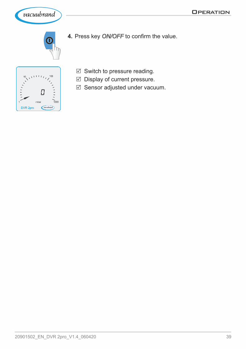
4. Press key ON/OFFON/OFF to confirm the value.
5 Switch to pressure reading. 5 Display of current pressure. 5 Sensor adjusted under vacuum.

40 20901502_EN_DVR 2pro_V1.4_060420
Resolving problems
7 7 Resolving problemsResolving problems
CAUTIONMalfunction because of incorrect repair by the customer.The gauge is not intended for the repair by customer.> Open the vacuum gauge only for battery replacement.> If the gauge is defective, please send it to our Service Department or your local supplier.
Technical support > To identify errors and potential remedies, please refer to the troubleshooting table: Fault – Cause – RemedyFault – Cause – Remedy
For technical help or in case of errors, please contact our Service1 department.
7.1 7.1 Error displayError displayIn case of malfunction a warning triangle appears on the display.
Example error display
2
1
1 Warning triangle blinks2 Measure display blinks
` here: over pressure
1 -> Phone: +49 9342 808-5660, Fax: +49 9342 808-5555, [email protected]
ExampleError display
Technical support

4120901502_EN_DVR 2pro_V1.4_060420
Resolving problems
7.2 7.2 Fault – Cause – RemedyFault – Cause – Remedy
FaultFault ` Possible cause 3Remedy over pressure
Blinking cycle pressure reading and warning tri-angle
` Pressure too high.` Measuring range exceeded.
WARNING!Risk of bursting.
>Discharge the system imme‑diately by Venting.
3 Vent the system or appara‑tus.3 Reduce pressure.3 Perform sensor adjustment.
Under range
Blinking cycle pressure reading and warning tri-angle
` Measuring range fallen below.
3 Pressure reading until 0 mbar (0 Torr).3 Perform sensor adjustment.
Front glass broken ` Wrong cleaning agent used.` Mechanically damaged.
3 Send in gauge.
Wrong pressure read‑ings displayed
` Sensor measures incor‑rectly.` Vacuum sensor polluted.` Defective sensor.
3 Clean sensor3 Perform sensor adjustment.3 Send in gauge.
Battery icon and/or dis‑play blinks
` Battery low. 3 Replace battery.
No display ` Device switched off` Power‑on time elapsed.` No voltage, battery empty or defective or wrong poled.
3 Switch on device3 Extend power‑on time.3 Check battery fastening.3 Replace battery.
Adjustment mode can‑not be called‑up
Blinking warning triangle, pressure reading = - - -
` A for sensor adjustment inadmissible pressure is reached (no adjustment possible in between pressure range 21 – 699 mbar).
3 Perform adjustment at min. > 700 mbar atmo‑spheric pressure or vacuum < 20 mbar.3 For adjustment connect a vacuum pump with pre‑cise vacuum and then move pump down to the possible pressure range.
Display of all LCD icons orno display despite of battery replacment.
` Defective sensor.` Defecitve measuring equip‑ment
3 Send in gauge.
42 20901502_EN_DVR 2pro_V1.4_060420
Appendix
8 8 AppendixAppendix
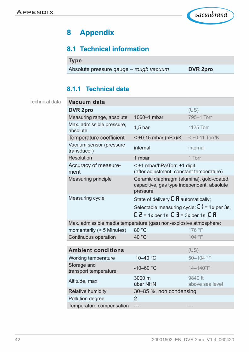
8.1 8.1 Technical informationTechnical informationTypeAbsolute pressure gauge – rough vacuum DVR 2pro
8.1.1 8.1.1 Technical dataTechnical data
Vacuum dataDVR 2pro (US)Measuring range, absolute 1060–1 mbar 795–1 TorrMax. admissible pressure, absolute 1,5 bar 1125 Torr
Temperature coefficient < ±0.15 mbar (hPa)/K < ±0.11 Torr/KVacuum sensor (pressure transducer) internal internal
Resolution 1 mbar 1 TorrAccuracy of measure‑ment
< ±1 mbar/hPa/Torr, ±1 digit (after adjustment, constant temperature)
Measuring principle Ceramic diaphragm (alumina), gold‑coated, capacitive, gas type independent, absolute pressure
Measuring cycle State of delivery C AC A automatically;Selectable measuring cycle: C 1C 1 = 1x per 3s, C 2C 2 = 1x per 1s, C 3C 3 = 3x per 1s, C AC A
Max. admissible media temperature (gas) non‑explosive atmosphere:momentarily (< 5 Minutes) 80 °C 176 °FContinuous operation 40 °C 104 °F
Ambient conditions (US)Working temperature 10–40 °C 50–104 °FStorage and transport temperature ‑10–60 °C 14–140°F
Altitude, max. 3000 müber NHN
9840 ftabove sea level
Relative humidity 30–85 %, non condensingPollution degree 2Temperature compensation ‑‑‑ ‑‑‑
Technical data

4320901502_EN_DVR 2pro_V1.4_060420
Appendix
ConnectionsVacuum connection Small flange KF DN 16
Hose nozzle DN 6/10
Electrical data vacuum gaugePower supplyAlkaline battery 9 VDC
Battery lifetime at Measuring cycle C2C2, approx.
4000 h
Protection type / Impact energy IP 40 / 5 J
DisplayType LC display (LCD)Pressure reading switchable: mbar, Torr, hPaAutomatic switch‑off State of delivery 5 minutes
Power‑on time selectable 1–600 Minutes orOnOn = Continuous operation
Weight and dimensions (US)Weight, approx. 400 g 0.88 lbDimension with small flange KF
115 mm x 115 mm x 56 mm5 in. x 5 in. x 2.2 in.
Measurement chamber inner volume (without hose nozzle)
4,23 cm3 0.26 in3
8.1.2 8.1.2 Wetted materialsWetted materials
Component Wetted materialsVacuum sensor Aluminium oxide ceramics, gold‑coatedSensor housing PBT GK 30Sealings chemically resistant fluorelastomerConnection flange KF PP GF 30Hose nozzle PP
Technical data
Wetted materials

44 20901502_EN_DVR 2pro_V1.4_060420
Appendix
8.1.3 8.1.3 Device dataDevice data
> In case of malfunction, please note type and serial number on the rating plate.> When contacting our service department, name us product type and serial number. With this information we can offer selective support and advice for your product.
Device data on rear side of the gauge
Manufacturer + address
Serial number
Voltage supply
Rating plate data

4520901502_EN_DVR 2pro_V1.4_060420
Appendix
Ordering information accessories
8.2 8.2 Ordering informationOrdering information
Vacuum gauge Order N°DVR 2pro 20682906
Accessories Order N°PTFE hose KF DN 16 (l = 1000 mm) 20686031Vacuum rubber hose DN 6 mm 20686000Clamping ring KF DN 16 20660000Centering ring KF DN 16 20660124DAkkS calibration with first delivery 20900214DAkkS recalibration 20900215
Spare parts Order N°Support rod 20682839Small flange KF 16 PPProtective cap DN 10/16O‑ring
20635110
Knurled nut M14x1 (union nut) 20637657Hose nozzle DN 6/10 20636635Locking ring for knurled nut 206376589 V Block‑type battery, enclosedrecommended types: alkali-manganese or lithium-ion
20612891
Instructions for use 20901502Safety Information for Vacuum Equipment 20999254
Source of supplyPurchase original accessories and spare parts from your special‑ized distributor or through international sales offices of VACU‑UBRAND GMBH + CO KG.
> Information about the complete product range are available in the current product catalog.> For orders, questions about vacuum control and optimal accessories, please contact your specialized distributor or an international sales office of VACUUBRAND GMBH + CO KG.
Ordering information spare parts
International sales offices and specialized trade

46 20901502_EN_DVR 2pro_V1.4_060420
Appendix
8.3 8.3 ServiceServiceTake advantage of the comprehensive service range of VACUUBRAND GMBH + CO KG.
Service in detail � product guidance and practical solutions, � fast delivery of spare parts and accessories, � professional maintenance, � immediate repairs processing, � Service on the spot (on request), � Calibration (DAkkS accredited), � return, disposal.
>Visit our website for further information: www.vacuubrand.com.
Servicing handling
1. Contact your local supplier or our Service Department.2. Request a RMA number for your order.3. Remove the battery, clean the product thoroughly and if neces‑
sary decontaminate it professionally.4. Please fill in this form Health and Safety Clearance completely.5. Return your product including:
� RMA‑N°, � Repair‑ or service order, � Form Health and Safety Clearance, � short error description.
> Reduce downtime, speed up the service process. Please keep the required data and documents ready when contacting our Service Department.` Your order can be quickly and easily processed.` Hazards can be excluded.` A short description or photos may help for error location.
Service offer and service range
Meet the terms of service
Return (reshipment)
4720901502_EN_DVR 2pro_V1.4_060420
Appendix
8.4 8.4 IndexIndex
AAccessories . . . . . . . . . . . . . . . . . . 45Action step . . . . . . . . . . . . . . . . . . . . . 8Atmospheric pressure . . . . . . . . . . . 35
BBlock‑type battery (battery list) . . . . 45
Ccaptive screw . . . . . . . . . . . . . . . . . . 16Cleaning . . . . . . . . . . . . . . . . . . . . . 33Clean sensor . . . . . . . . . . . . . . . . . . 33Clean surface . . . . . . . . . . . . . . . . . 33Connection options . . . . . . . . . . . . . 22Contact . . . . . . . . . . . . . . . . . . . . . . . 5Copyright © . . . . . . . . . . . . . . . . . . . . 6Correct battery handling . . . . . . . . . 13
DDelivery state automatic switch‑off . 30Device data . . . . . . . . . . . . . . . . . . . 44Device name . . . . . . . . . . . . . . . . . . 15Display battery discharge state . . . . 32Display elements DVR 2pro . . . . . . 27Display icons DVR 2pro . . . . . . . . . . 28
EEC Declaration of Conformity . . . . . 48Entsorgung . . . . . . . . . . . . . . . . . . . 13Error display . . . . . . . . . . . . . . . . . . 40Examples of use: . . . . . . . . . . . . . . . 18
FFault – Cause – Remedy . . . . . . . . . 41Foreseeable misuse . . . . . . . . . . . . 11Front and rear side . . . . . . . . . . . . . 15
GGauge description . . . . . . . . . . . . . . 15Goods arrival . . . . . . . . . . . . . . . . . . 14
HHandling instruction . . . . . . . . . . . . . . 8Health and Safety Clearance . . . . . . 46
IIcons . . . . . . . . . . . . . . . . . . . . . . . . . 7Improper use . . . . . . . . . . . . . . 10, 11Included materials . . . . . . . . . . . . . . 14Insert battery . . . . . . . . . . . . . . . . . . 20Installation . . . . . . . . . . . . . . . . . . . . 19Installation conditions . . . . . . . . . . . 19Intended use . . . . . . . . . . . . . . . . . . 10
JJump‑back times . . . . . . . . . . . . . . . 26
KKey combination . . . . . . . . . . . . . . . 26Key function . . . . . . . . . . . . . . . . . . . 25
LLimitation of use . . . . . . . . . . . . . . . 19
MMandatory sign . . . . . . . . . . . . . . . . . 7Measuring cycle . . . . . . . . . . . . 28, 31
OOperating elements . . . . . . . . . . . . . 25Operating elements DVR 2pro . . . . 25Ordering information . . . . . . . . . . . . 45
PPersonnel (staff) . . . . . . . . . . . . . . . 12Presentation convention operating steps . . . . . . . . . . . . . . . . . . . . . . . . . 8Prohibition symbol . . . . . . . . . . . . . . . 7Proper disposal . . . . . . . . . . . . . . . . 13
RRating plate . . . . . . . . . . . . . . . . . . . 44Rating plate data . . . . . . . . . . . . . . . 44Rear view . . . . . . . . . . . . . . . . . . . . . 16Replace battery . . . . . . . . . . . . . . . . 20Resolving problems . . . . . . . . . . . . . 40Return (reshipment) . . . . . . . . . . . . . 46
SSafety . . . . . . . . . . . . . . . . . . . . . . . . 5Safety Information for Vacuum Equip‑ment . . . . . . . . . . . . . . . . . . . . . . . . . 10Safety instructions . . . . . . . . . . . . . . 10Safety precautions . . . . . . . . . . . . . . 12Sales offices . . . . . . . . . . . . . . . . . . 45Sensor . . . . . . . . . . . . . . . . . . . . . . . 42Service range . . . . . . . . . . . . . . . . . 46Servicing handling . . . . . . . . . . . . . . 46Side view . . . . . . . . . . . . . . . . . . . . . 15Signals . . . . . . . . . . . . . . . . . . . . . . . . 7Source of supply . . . . . . . . . . . . . . . 45Spare parts . . . . . . . . . . . . . . . . . . . 45Symbols . . . . . . . . . . . . . . . . . . . . . . . 7
TTechnical data . . . . . . . . . . . . . 42, 43Technical information . . . . . . . . . . . . 42Technical support . . . . . . . . . . . . . . . 40
UUser information . . . . . . . . . . . . . . . . 5
VVacuum connection . . . . . . . . . . . . . 22Vacuum sensor . . . . . . . . . . . . . . . . 42
WWarning levels . . . . . . . . . . . . . . . . . . 6Warning symbol . . . . . . . . . . . . . . . . . 7Wetted materials . . . . . . . . . . . . . . . 43
Index

48 20901502_EN_DVR 2pro_V1.4_060420
Appendix
8.5 8.5 EC Declaration of ConformityEC Declaration of Conformity
EU‑KonformitätserklärungEC Declaration of ConformityDéclaration CE de conformité
Hersteller / Manufacturer / Fabricant:
VACUUBRAND GMBH + CO KG · Alfred‑Zippe‑Str. 4 · 97877 Wertheim · Germany
Hiermit erklärt der Hersteller, dass das Gerät konform ist mit den Bestimmungen der Richtlinien:
Hereby the manufacturer declares that the device is in conformity with the directives:
Par la présente, le fabricant déclare, que le dispositif est conforme aux directives:
2014/30/EU (EMV‑RL), 2011/65/EU, 2015/863 (RoHS‑RL)
Vakuummessgerät / Vacuum gauge / Vacuomètre
Typ / Type / Type: DVR 2pro
Artikelnummer / Order number / Numéro d‘article: 2068290620682906
Seriennummer / Serial number / Numéro de série: Siehe Typenschild / See rating plate / Voir plaque signalétique
Angewandte harmonisierte Normen / Harmonized standards applied / Nor‑mes harmonisées utilisées: DIN EN 12100:2011; DIN EN 61326‑1:2013; DIN EN 61010‑1:2011, IEC 61010‑1:2010 (Ed. 3); DIN EN IEC 63000:2019
Bevollmächtigter für die Zusammenstellung der technischen Unterlagen / Person authorised to compile the technical file / Personne autorisée à constituer le dos‑sier technique: Dr. F. Gitmans · VACUUBRAND GMBH + CO KG · Germany
Ort, Datum / place, date / lieu, date: Wertheim, 13.01.2020
i. A.
(Dr. F. Gitmans) (Dr. A. Wollschläger)Geschäftsführer / Managing Director / Gérant
Regulatory Affairs Manager / Directrice des affaires réglementaires
VACUUBRAND GMBH + CO KGVACUUBRAND GMBH + CO KG
Alfred‑Zippe‑Str. 4 97877 Wertheim
Tel.: +49 9342 808‑0 Fax: +49 9342 808‑5555 E‑Mail: [email protected] Web: www.vacuubrand.com
50 20901502_EN_DVR 2pro_V1.4_060420
Appendix
8.6 8.6 Declaration of Conformity – China RoHS 2Declaration of Conformity – China RoHS 2
Declaration of Conformity – China RoHS 2 V4_April 2020 Copyright 2020
DECLARATION OF CONFORMITY – China RoHS 2
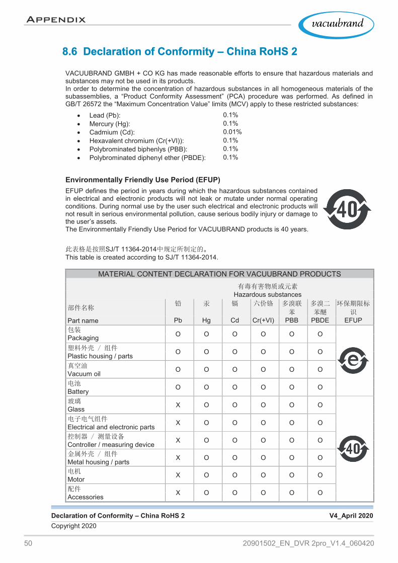
VACUUBRAND GMBH + CO KG has made reasonable efforts to ensure that hazardous materials and
substances may not be used in its products. In order to determine the concentration of hazardous substances in all homogeneous materials of the subassemblies, a “Product Conformity Assessment” (PCA) procedure was performed. As defined in GB/T 26572 the “Maximum Concentration Value” limits (MCV) apply to these restricted substances:
Lead (Pb): 0.1% Mercury (Hg): 0.1% Cadmium (Cd): 0.01% Hexavalent chromium (Cr(+VI)): 0.1% Polybrominated biphenlys (PBB): 0.1% Polybrominated diphenyl ether (PBDE): 0.1%
Environmentally Friendly Use Period (EFUP)
EFUP defines the period in years during which the hazardous substances contained in electrical and electronic products will not leak or mutate under normal operating conditions. During normal use by the user such electrical and electronic products will not result in serious environmental pollution, cause serious bodily injury or damage to the user’s assets. The Environmentally Friendly Use Period for VACUUBRAND products is 40 years.
此表格是按照SJ/T 11364‑2014中规定所制定的。 This table is created according to SJ/T 11364‑2014.
MATERIAL CONTENT DECLARATION FOR VACUUBRAND PRODUCTS 有毒有害物质或元素
Hazardous substances
部件名称 铅 汞 镉 六价铬 多溴联
苯
多溴二
苯醚
环保期限标
识
Part name Pb Hg Cd Cr(+VI) PBB PBDE EFUP 包装
Packaging O O O O O O
塑料外壳 / 组件 Plastic housing / parts O O O O O O
真空油 Vacuum oil O O O O O O
电池 Battery O O O O O O
玻璃 Glass X O O O O O
电子电气组件
Electrical and electronic parts X O O O O O 控制器 / 测量设备
Controller / measuring device X O O O O O 金属外壳 / 组件
Metal housing / parts X O O O O O 电机
Motor X O O O O O 配件
Accessories X O O O O O

5120901502_EN_DVR 2pro_V1.4_060420
Appendix
Declaration of Conformity – China RoHS 2 V4_April 2020Copyright 2020
注注释释:: 此表格适用于所有产品。以上列出的元件或组件不一定都属于所附产品的组成。 Note: Table applies to all products. Some of the components or parts listed above may not be part of
the enclosed product.
O: 表示该有毒有害物质在该部件所有均质材料中的含量均在GB/T 26572规定的限量要求以下。 O: Indicates that the above mentioned hazardous substance contained in all homogeneous mate‑
rials of the part is below the required limit as defined in GB/T 26572.
X: 表示该有毒有害物质至少在该部件某一均质材料中的含量超出GB/T 26572规定的限量要求。 X: Indicates that the above mentioned hazardous substance contained in at least one of the ho‑
mogeneous materials of this part is above the required limit as defined in GB/T 26572.
除上表所示信息外,还需声明的是,这些部件并非是有意用铅(Pb)、 汞 (Hg)、铬(Cd)、六价铬
(Cr(+VI))、多溴联苯(PBB)或多溴二苯醚(PBDE)来制造的。Apart from the disclosures in the above table, the subassemblies are not intentionally manufactured or formulated with lead (Pb), mercury (Hg), cadmium (Cd), hexavalent chromium (Cr+VI), polybrominated biphenyls (PBB), and polybrominated diphenyl ethers (PBDE).
Products manufactured by VACUUBRAND may enter into further devices (e.g., rotary evaporator) or can be used together with other appliances (e.g., usage as booster pumps).With these products and appliances in particular, please note the EFUP labeled on these products.VACUUBRAND will not take responsibility for the EFUP of those products and appliances.
Place, date: Wertheim, 06/04/2020
i.A.(Dr. F. Gitmans) (Dr. A. Wollschläger)Managing Director Regulatory Affairs Manager
VACUUBRAND GMBH + CO KG Tel.: +49 9342 808‑0Alfred‑Zippe‑Str. 4 Fax: +49 9342 808‑555597877 Wertheim E‑Mail: [email protected] Web: www.vacuubrand.com

Manufacturer:VACUUBRAND GMBH + CO KGAlfred‑Zippe‑Str. 497877 WertheimGERMANY
Phone: � Head office +49 9342 808‑0 � Sales +49 9342 808‑5550 � Service +49 9342 808‑5660
Fax: +49 9342 808‑5555E‑Mail: [email protected]: www.vacuubrand.com
Technology for Vacuum Systems
Vers
ión:
209
0150
2_E
N_D
VR
2pr
o_V
1.4_
0604
20
TDD
2 ©
VA
CU
UB
RA
ND
GM
BH
+ C
O K
G –
202
0