Embed Size (px)
Citation preview
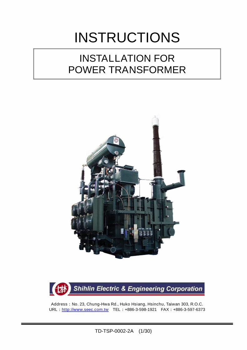
TD-TSP-0002-2A (1/30)
INSTRUCTIONS
INSTALLATION FORPOWER TRANSFORMER
Address:No. 23, Chung-Hwa Rd., Huko Hsiang, Hsinchu, Taiwan 303, R.O.C.
URL:http://www.seec.com.tw TEL:+886-3-598-1921 FAX:+886-3-597-6373
TD-TSP-0002-2A (2/30)
〇 General Caution For Installation
1. PREPARATION
(1) Construct the foundation correctly in accordance with the foundation drawing or the outline drawing before the
arrival of the main body.
(2) Prepare necessary equipment, tools and parts before starting the installation work.
(3) After arrival the main body and accessories at site, check the packages with the packing list and also investigate
damages of the components.
(4) As the main body is transported filled with the insulating oil, be sure that the oil leakage is nothing and the
internal pressure is positive value by reading of the pressure gauge mounted on the main body.
(5) It is preferable to store the accessories inside a building. However where they are outdoors, cover them with a
suitable sheets. Don’t expose them to the weather.
2. INSTALLATION
(1) General
(a) Don’t give excessive forces or heavy shock to main body and accessories.
(b) Avoid installation under rain. (for outdoor installation)
(c) Exercise care so that dust, dirt and moisture will not enter inside of the main body and accessories.
(d) Cover the open places with vinyl sheets till just before installation in order to prevent entrance of dust.
(e) Handle gaskets with care so as not to injure.
(f) Don’t remove the cover plates of main body and piping till just before installation.
(g) Fasten bolts with adequate fastening torque. (Refer to following item “Application and torque of tightening bolts”.)
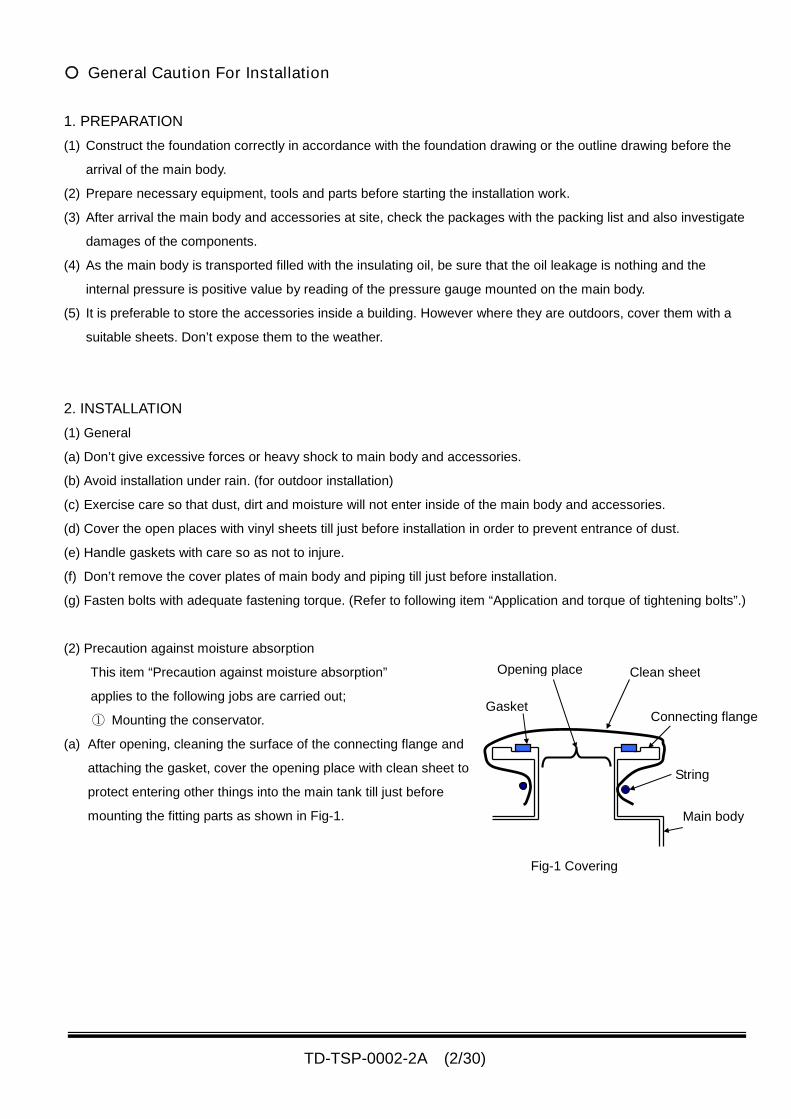
(2) Precaution against moisture absorption
This item “Precaution against moisture absorption”
applies to the following jobs are carried out;
① Mounting the conservator.
(a) After opening, cleaning the surface of the connecting flange and
attaching the gasket, cover the opening place with clean sheet to
protect entering other things into the main tank till just before
mounting the fitting parts as shown in Fig-1.
Fig-1 Covering
String
Main body
Connecting flangeGasket
Clean sheetOpening place
TD-TSP-0002-2A (3/30)
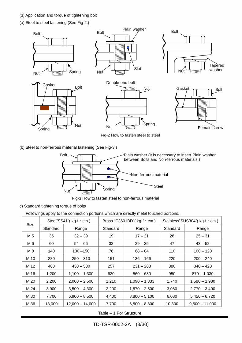
(3) Application and torque of tightening bolt
(a) Steel to steel fastening (See Fig-2.)
(b) Steel to non-ferrous material fastening (See Fig-3.)
c) Standard tightening torque of bolts
Followings apply to the connection portions which are directly metal touched portions.
Steel”SS41”( kg-f・cm ) Brass “C3601BD”( kg-f・cm ) Stainless”SUS304”( kg-f・cm )Size
Standard Range Standard Range Standard Range
M 5 35 32 – 39 19 17 – 21 28 25 – 31
M 6 60 54 – 66 32 29 – 35 47 43 – 52
M 8 140 130 –150 76 68 – 84 110 100 – 120
M 10 280 250 – 310 151 136 – 166 220 200 – 240
M 12 480 430 – 530 257 231 – 283 380 340 – 420
M 16 1,200 1,100 – 1,300 620 560 – 680 950 870 – 1,030
M 20 2,200 2,000 – 2,500 1,210 1,090 – 1,333 1,740 1,580 – 1,980
M 24 3,900 3,500 – 4,300 2,200 1,870 – 2,500 3,080 2,770 – 3,400
M 30 7,700 6,900 – 8,500 4,400 3,800 – 5,100 6,080 5,450 – 6,720
M 36 13,000 12,000 – 14,000 7,700 6,500 – 8,800 10,300 9,500 – 11,000
Table – 1 For Structure
Fig-3 How to fasten steel to non-ferrous material
Bolt
Nut
Plain washer (It is necessary to insert Plain washerbetween Bolts and Non-ferrous materials.)
Non-ferrous material
Steel
Bolt
Nut
Bolt
Nut
Plain washer
Slot
Bolt
Nut
Taperedwasher
Bolt
Nut
GasketDouble-end bolt
Nut
Nut Bolt
Female screw
Gasket
Fig-2 How to fasten steel to steel
Spring
SpringSpring
Spring
TD-TSP-0002-2A (4/30)
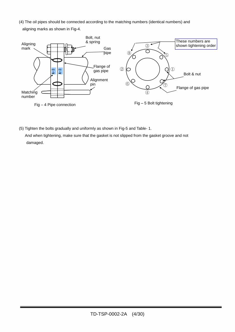
(4) The oil pipes should be connected according to the matching numbers (identical numbers) and
aligning marks as shown in Fig-4.
(5) Tighten the bolts gradually and uniformly as shown in Fig-5 and Table- 1.
And when tightening, make sure that the gasket is not slipped from the gasket groove and not
damaged.
Fig – 5 Bolt tightening
①
⑤
③
⑧
②
⑥
④
⑦
These numbers areshown tightening order
Flange of gas pipe
Bolt & nutA-3
A-3
Aligningmark
Matchingnumber
Bolt, nut& spring
Gaspipe
Alignmentpin
Flange ofgas pipe
Fig – 4 Pipe connection
TD-TSP-0002-2A (5/30)
1. PREPARATION FOR INSTALLTION.
1. Determining location for installation of transformer.
The location in which the transformer is to be installed must be accurately determined and preparations for
which such as the concrete foundation, base, anchor etc. should be completed prior to the arrival of the
transformer.
(1) The foundation must be laid as to maintain a correct horizontal level. Less than 3 mm is required for flatter level.
(2) It is necessary to secure the storage space of the parts and the installation equipment.
2. Equipment, tools and parts needed for installation
The followings are required to satisfy the specification described below.
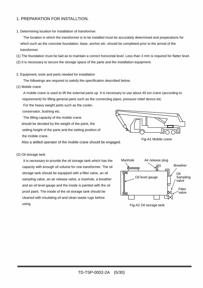
(1) Mobile crane
A mobile crane is used to lift the external parts up. It is necessary to use about 45 ton crane (according to
requirement) for lifting general parts such as the connecting pipes, pressure relief device etc.
For the heavy weight parts such as the cooler,
conservator, bushing etc.
The lifting capacity of the mobile crane
should be decided by the weight of the parts, the
setting height of the parts and the setting position of
the mobile crane.
Also a skilled operator of the mobile crane should be engaged.
(2) Oil storage tank
It is necessary to provide the oil storage tank which has the
capacity with enough oil volume for one transformer. The oil
storage tank should be equipped with a filter valve, an oil
sampling valve, an air release valve, a manhole, a breather
and an oil level gauge and the inside is painted with the oil
proof paint. The inside of the oil storage tank should be
cleaned with insulating oil and clean waste rugs before
using. Fig-A2 Oil storage tank
Manhole Air release plug
Oil level gauge
Breather
OilSamplingvalve
Filtervalve
Fig-A1 Mobile crane
TD-TSP-0002-2A (6/30)
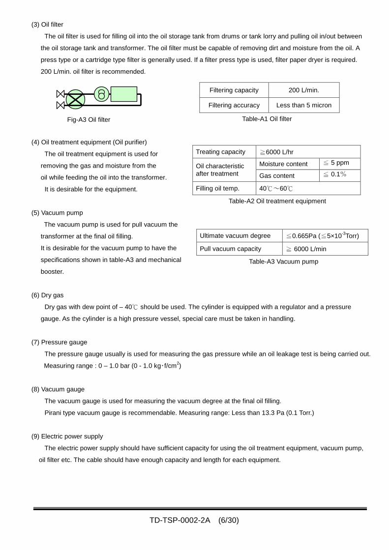
(3) Oil filter
The oil filter is used for filling oil into the oil storage tank from drums or tank lorry and pulling oil in/out between
the oil storage tank and transformer. The oil filter must be capable of removing dirt and moisture from the oil. A
press type or a cartridge type filter is generally used. If a filter press type is used, filter paper dryer is required.
200 L/min. oil filter is recommended.
(4) Oil treatment equipment (Oil purifier)
The oil treatment equipment is used for
removing the gas and moisture from the
oil while feeding the oil into the transformer.
It is desirable for the equipment.
(5) Vacuum pump
The vacuum pump is used for pull vacuum the
transformer at the final oil filling.
It is desirable for the vacuum pump to have the
specifications shown in table-A3 and mechanical
booster.
(6) Dry gas
Dry gas with dew point of – 40℃ should be used. The cylinder is equipped with a regulator and a pressure
gauge. As the cylinder is a high pressure vessel, special care must be taken in handling.
(7) Pressure gauge
The pressure gauge usually is used for measuring the gas pressure while an oil leakage test is being carried out.
Measuring range : 0 – 1.0 bar (0 - 1.0 kg・f/cm2)
(8) Vacuum gauge
The vacuum gauge is used for measuring the vacuum degree at the final oil filling.
Pirani type vacuum gauge is recommendable. Measuring range: Less than 13.3 Pa (0.1 Torr.)
(9) Electric power supply
The electric power supply should have sufficient capacity for using the oil treatment equipment, vacuum pump,
oil filter etc. The cable should have enough capacity and length for each equipment.
Fig-A3 Oil filter
Filtering capacity 200 L/min.
Filtering accuracy Less than 5 micron
Table-A1 Oil filter
Treating capacity ≧6000 L/hr
Moisture content ≦ 5 ppmOil characteristicafter treatment Gas content ≦ 0.1%
Filling oil temp. 40℃~60℃
Table-A2 Oil treatment equipment
Ultimate vacuum degree ≦0.665Pa (≦5×10⁻³
Torr)
Pull vacuum capacity ≧ 6000 L/min
Table-A3 Vacuum pump
TD-TSP-0002-2A (7/30)
(10) Oil tester
The oil tester should be prepared at site during installation because the oil tester is used to measure the
breakdown voltage(dielectric strength) of the insulating oil when oil receiving, oil filling to main tank, before final oil
filling to main tank etc.. 0 – 80 kV/2.5mm・Gap oil tester is recommendable.
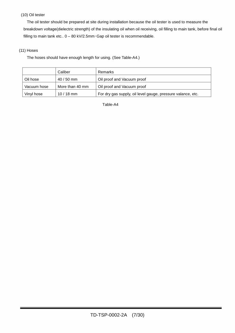
(11) Hoses
The hoses should have enough length for using. (See Table-A4.)
Caliber Remarks
Oil hose 40 / 50 mm Oil proof and Vacuum proof
Vacuum hose More than 40 mm Oil proof and Vacuum proof
Vinyl hose 10 / 18 mm For dry gas supply, oil level gauge, pressure valance, etc.
Table-A4
TD-TSP-0002-2A (8/30)
2. RECEIVING INSPECTION
1. Inspection
(1). Main body
When the transformer has arrived at site,
inspect the appearance of the main body, and
also check the dry (or nitrogen) gas pressure in the
transformer by the pressure gauge mounted on the
main body.
If there are any damages and rust on the main body,
you should eliminate or repair them as soon as
possible.
In case that the damage is serious and the
effective treatment can not be made by you,
please inform the detailed damage condition to
Shihlin Electric immediately.
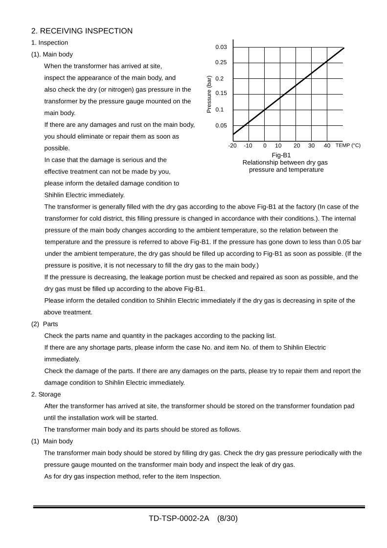
The transformer is generally filled with the dry gas according to the above Fig-B1 at the factory (In case of the
transformer for cold district, this filling pressure is changed in accordance with their conditions.). The internal
pressure of the main body changes according to the ambient temperature, so the relation between the
temperature and the pressure is referred to above Fig-B1. If the pressure has gone down to less than 0.05 bar
under the ambient temperature, the dry gas should be filled up according to Fig-B1 as soon as possible. (If the
pressure is positive, it is not necessary to fill the dry gas to the main body.)
If the pressure is decreasing, the leakage portion must be checked and repaired as soon as possible, and the
dry gas must be filled up according to the above Fig-B1.
Please inform the detailed condition to Shihlin Electric immediately if the dry gas is decreasing in spite of the
above treatment.
(2) Parts
Check the parts name and quantity in the packages according to the packing list.
If there are any shortage parts, please inform the case No. and item No. of them to Shihlin Electric
immediately.
Check the damage of the parts. If there are any damages on the parts, please try to repair them and report the
damage condition to Shihlin Electric immediately.
2. Storage
After the transformer has arrived at site, the transformer should be stored on the transformer foundation pad
until the installation work will be started.
The transformer main body and its parts should be stored as follows.
(1) Main body
The transformer main body should be stored by filling dry gas. Check the dry gas pressure periodically with the
pressure gauge mounted on the transformer main body and inspect the leak of dry gas.
As for dry gas inspection method, refer to the item Inspection.
-20 -10 0 10 20 30 40 TEMP (°C)
0.05
0.1
0.25
0.15
0.2
0.03
Pre
ssu
re(b
ar)
Fig-B1Relationship between dry gas
pressure and temperature
TD-TSP-0002-2A (9/30)
(2) Parts
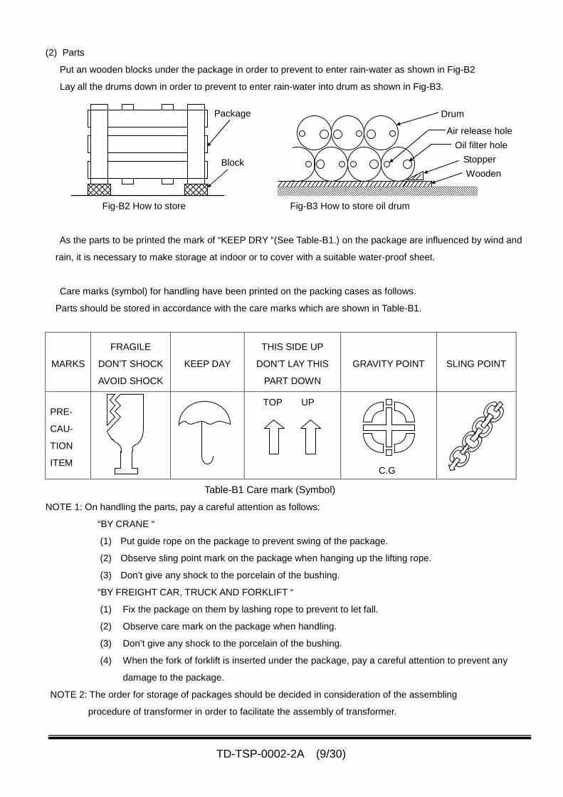
Put an wooden blocks under the package in order to prevent to enter rain-water as shown in Fig-B2
Lay all the drums down in order to prevent to enter rain-water into drum as shown in Fig-B3.
Fig-B2 How to store Fig-B3 How to store oil drum
As the parts to be printed the mark of “KEEP DRY “(See Table-B1.) on the package are influenced by wind and
rain, it is necessary to make storage at indoor or to cover with a suitable water-proof sheet.
Care marks (symbol) for handling have been printed on the packing cases as follows.
Parts should be stored in accordance with the care marks which are shown in Table-B1.
MARKS
FRAGILE
DON’T SHOCK
AVOID SHOCK
KEEP DAY
THIS SIDE UP
DON’T LAY THIS
PART DOWN
GRAVITY POINT SLING POINT
PRE-
CAU-
TION
ITEM
TOP UP
C.G
Table-B1 Care mark (Symbol)
NOTE 1: On handling the parts, pay a careful attention as follows:
“BY CRANE “
(1) Put guide rope on the package to prevent swing of the package.
(2) Observe sling point mark on the package when hanging up the lifting rope.
(3) Don’t give any shock to the porcelain of the bushing.
“BY FREIGHT CAR, TRUCK AND FORKLIFT “
(1) Fix the package on them by lashing rope to prevent to let fall.
(2) Observe care mark on the package when handling.
(3) Don’t give any shock to the porcelain of the bushing.
(4) When the fork of forklift is inserted under the package, pay a careful attention to prevent any
damage to the package.
NOTE 2: The order for storage of packages should be decided in consideration of the assembling
procedure of transformer in order to facilitate the assembly of transformer.
Package
Block
Drum
Wooden
Oil filter hole
Air release hole
Stopper
TD-TSP-0002-2A (10/30)
3. MAIN BODY ON FOUNDATION
1. When the main body has been arrived site, check the appearance for any damage caused during transit.
(1) Checking of foundation
Before arrival of the main body, followings should be done;
(2) Check the level of the foundation. The horizontal level of the foundation should be within 3 mm.
(3) Clean the floor of the foundation and draw base lines on the foundation in accordance with the
“FOUNDATION DRAWING” supplied by Shihlin Electric.
2. Positioning
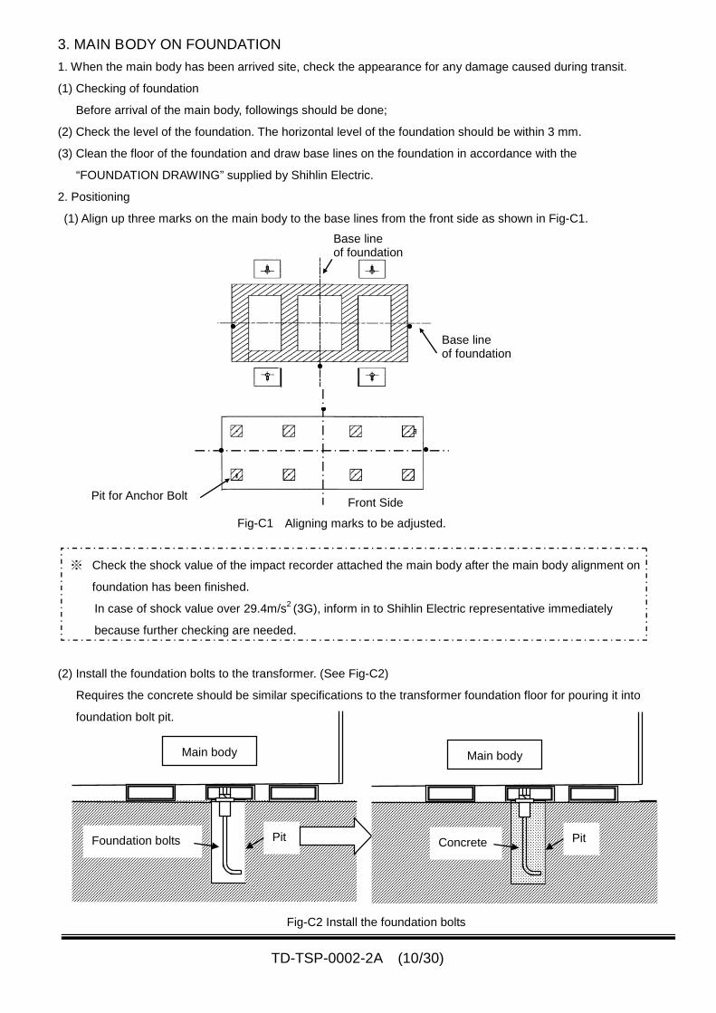
(1) Align up three marks on the main body to the base lines from the front side as shown in Fig-C1.
※ Check the shock value of the impact recorder attached the main body after the main body alignment on
foundation has been finished.
In case of shock value over 29.4m/s2(3G), inform in to Shihlin Electric representative immediately
because further checking are needed.
(2) Install the foundation bolts to the transformer. (See Fig-C2)
Requires the concrete should be similar specifications to the transformer foundation floor for pouring it into
foundation bolt pit.
Front Side
Base lineof foundation
Aligning marks to be adjusted.Fig-C1
Base lineof foundation
Pit for Anchor Bolt
Fig-C2 Install the foundation bolts
Foundation bolts Pit Concrete Pit
Main body Main body
TD-TSP-0002-2A (11/30)
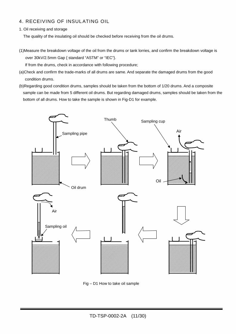
4. RECEIVING OF INSULATING OIL
1. Oil receiving and storage
The quality of the insulating oil should be checked before receiving from the oil drums.
(1)Measure the breakdown voltage of the oil from the drums or tank lorries, and confirm the breakdown voltage is
over 30kV/2.5mm Gap { standard “ASTM” or “IEC”}.
If from the drums, check in accordance with following procedure;
(a)Check and confirm the trade-marks of all drums are same. And separate the damaged drums from the good
condition drums.
(b)Regarding good condition drums, samples should be taken from the bottom of 1/20 drums. And a composite
sample can be made from 5 different oil drums. But regarding damaged drums, samples should be taken from the
bottom of all drums. How to take the sample is shown in Fig-D1 for example.
Fig – D1 How to take oil sample
Air
Sampling oil
Sampling pipe
Sampling cupThumb
Air
Oil
Oil drum
TD-TSP-0002-2A (12/30)
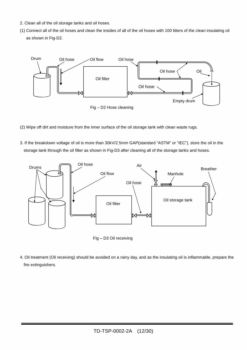
2. Clean all of the oil storage tanks and oil hoses.
(1) Connect all of the oil hoses and clean the insides of all of the oil hoses with 100 litters of the clean insulating oil
as shown in Fig-D2.
(2) Wipe off dirt and moisture from the inner surface of the oil storage tank with clean waste rugs.
3. If the breakdown voltage of oil is more than 30kV/2.5mm GAP(standard “ASTM” or “IEC”), store the oil in the
storage tank through the oil filter as shown in Fig-D3 after cleaning all of the storage tanks and hoses.
4. Oil treatment (Oil receiving) should be avoided on a rainy day, and as the insulating oil is inflammable, prepare the
fire extinguishers.
Fig – D2 Hose cleaning
Drum
Oil filter
Oil flow
Oil
Oil hose
Oil hose
Oil hose
Empty drum
Oil hose
Fig – D3 Oil receiving
Oil filter
Drums
Oil flow
Oil hose
Oil hose
Oil storage tank
Manhole
AirBreather
TD-TSP-0002-2A (13/30)
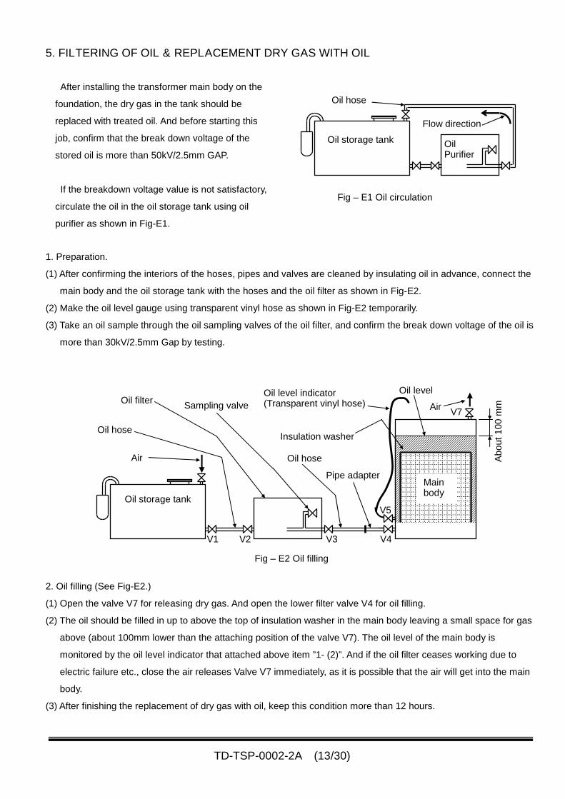
5. FILTERING OF OIL & REPLACEMENT DRY GAS WITH OIL
After installing the transformer main body on the
foundation, the dry gas in the tank should be
replaced with treated oil. And before starting this
job, confirm that the break down voltage of the
stored oil is more than 50kV/2.5mm GAP.
If the breakdown voltage value is not satisfactory,
circulate the oil in the oil storage tank using oil
purifier as shown in Fig-E1.
1. Preparation.
(1) After confirming the interiors of the hoses, pipes and valves are cleaned by insulating oil in advance, connect the
main body and the oil storage tank with the hoses and the oil filter as shown in Fig-E2.
(2) Make the oil level gauge using transparent vinyl hose as shown in Fig-E2 temporarily.
(3) Take an oil sample through the oil sampling valves of the oil filter, and confirm the break down voltage of the oil is
more than 30kV/2.5mm Gap by testing.
2. Oil filling (See Fig-E2.)
(1) Open the valve V7 for releasing dry gas. And open the lower filter valve V4 for oil filling.
(2) The oil should be filled in up to above the top of insulation washer in the main body leaving a small space for gas
above (about 100mm lower than the attaching position of the valve V7). The oil level of the main body is
monitored by the oil level indicator that attached above item ”1- (2)”. And if the oil filter ceases working due to
electric failure etc., close the air releases Valve V7 immediately, as it is possible that the air will get into the main
body.
(3) After finishing the replacement of dry gas with oil, keep this condition more than 12 hours.
Oil filter
Oil hose
Oil level
Air Abo
ut1
00
mm
Mainbody
Oil level indicator(Transparent vinyl hose)
Insulation washer
Sampling valve
Pipe adapter
Oil storage tank
Oil hose
V1 V2 V3 V4
V5
AirV7
Fig – E2 Oil filling
Oil hose
Oil storage tank OilPurifier
Flow direction
Fig – E1 Oil circulation
TD-TSP-0002-2A (14/30)
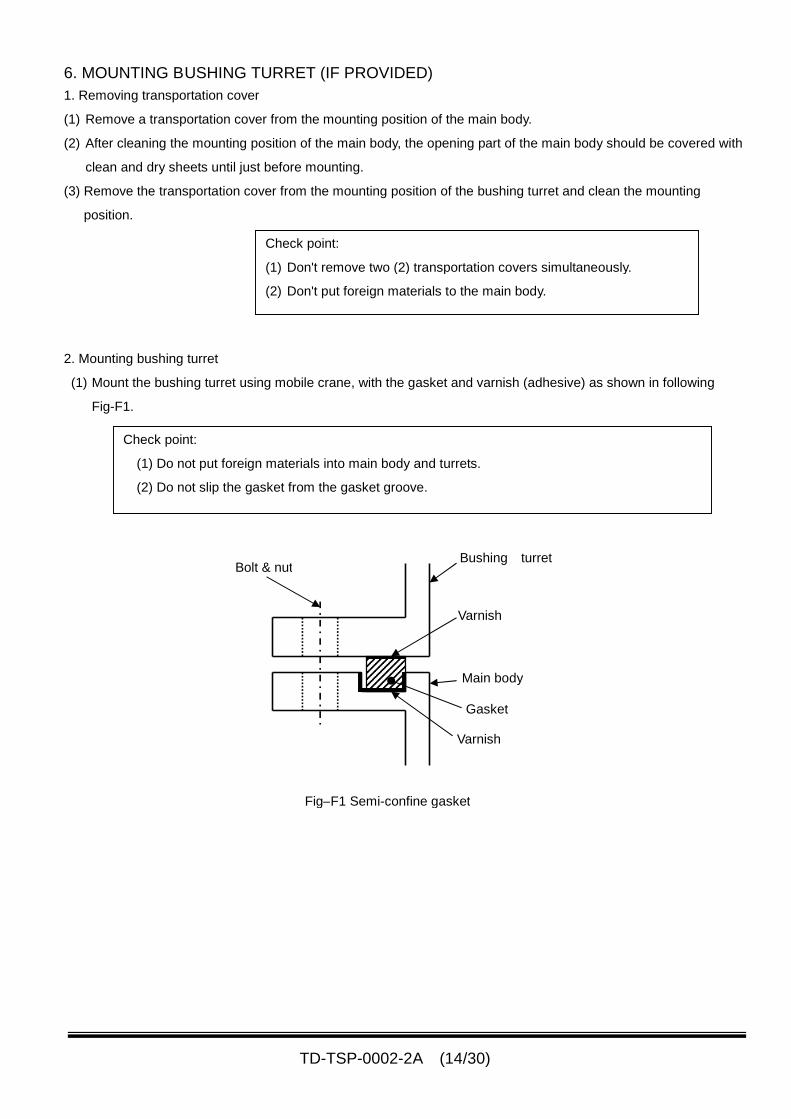
6. MOUNTING BUSHING TURRET (IF PROVIDED)
1. Removing transportation cover
(1) Remove a transportation cover from the mounting position of the main body.
(2) After cleaning the mounting position of the main body, the opening part of the main body should be covered with
clean and dry sheets until just before mounting.
(3) Remove the transportation cover from the mounting position of the bushing turret and clean the mounting
position.
2. Mounting bushing turret
(1) Mount the bushing turret using mobile crane, with the gasket and varnish (adhesive) as shown in following
Fig-F1.
Check point:
(1) Don't remove two (2) transportation covers simultaneously.
(2) Don't put foreign materials to the main body.
Fig–F1 Semi-confine gasket
Bushing turretBolt & nut
Varnish
Varnish
Main body
Gasket
Check point:
(1) Do not put foreign materials into main body and turrets.
(2) Do not slip the gasket from the gasket groove.
TD-TSP-0002-2A (15/30)
7. MOUNTING COOLING EQUIPMENT
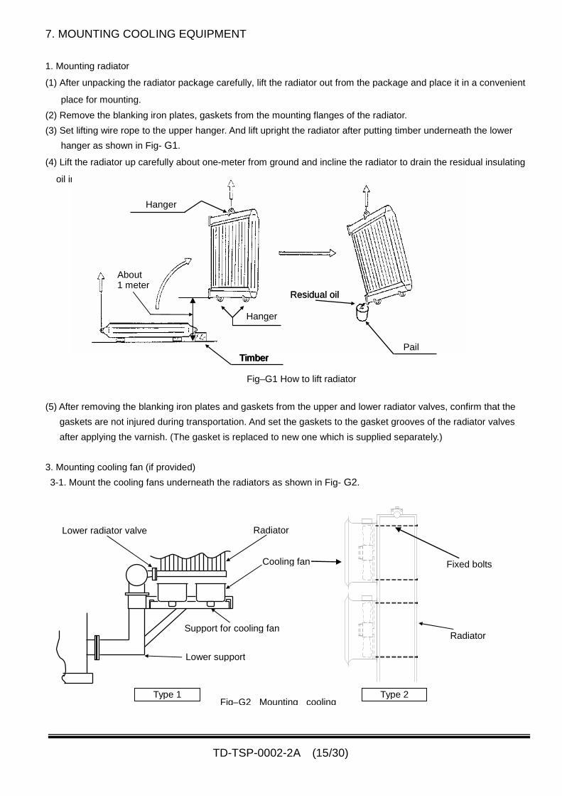
1. Mounting radiator
(1) After unpacking the radiator package carefully, lift the radiator out from the package and place it in a convenient
place for mounting.
(2) Remove the blanking iron plates, gaskets from the mounting flanges of the radiator.
(3) Set lifting wire rope to the upper hanger. And lift upright the radiator after putting timber underneath the lower
hanger as shown in Fig- G1.
(4) Lift the radiator up carefully about one-meter from ground and incline the radiator to drain the residual insulating
oil in the radiator as shown in Fig- G1.
(5) After removing the blanking iron plates and gaskets from the upper and lower radiator valves, confirm that the
gaskets are not injured during transportation. And set the gaskets to the gasket grooves of the radiator valves
after applying the varnish. (The gasket is replaced to new one which is supplied separately.)
3. Mounting cooling fan (if provided)
3-1. Mount the cooling fans underneath the radiators as shown in Fig- G2.
Hanger
Hanger
Timber
Residual oil
Pail
About1 meter
Fig–G1 How to lift radiator
Lower support
Fig–G2 Mounting cooling
Radiator
Cooling fan
Lower radiator valve
Support for cooling fanRadiator
Fixed bolts
Type 1 Type 2
Timber
Residual oil
Timber
TD-TSP-0002-2A (16/30)
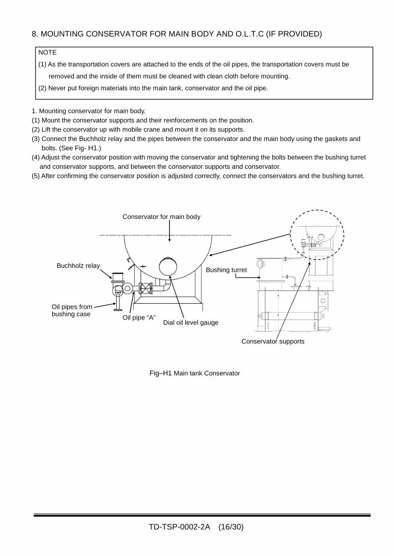
8. MOUNTING CONSERVATOR FOR MAIN BODY AND O.L.T.C (IF PROVIDED)
NOTE
(1) As the transportation covers are attached to the ends of the oil pipes, the transportation covers must be
removed and the inside of them must be cleaned with clean cloth before mounting.
(2) Never put foreign materials into the main tank, conservator and the oil pipe.
1. Mounting conservator for main body.
(1) Mount the conservator supports and their reinforcements on the position.
(2) Lift the conservator up with mobile crane and mount it on its supports.
(3) Connect the Buchholz relay and the pipes between the conservator and the main body using the gaskets and
bolts. (See Fig- H1.)
(4) Adjust the conservator position with moving the conservator and tightening the bolts between the bushing turret
and conservator supports, and between the conservator supports and conservator.
(5) After confirming the conservator position is adjusted correctly, connect the conservators and the bushing turret.
Fig–H1 Main tank Conservator
Oil pipe “A”
Conservator for main body
Buchholz relay
Oil pipes frombushing case
Dial oil level gauge
Conservator supports
Bushing turret
TD-TSP-0002-2A (17/30)
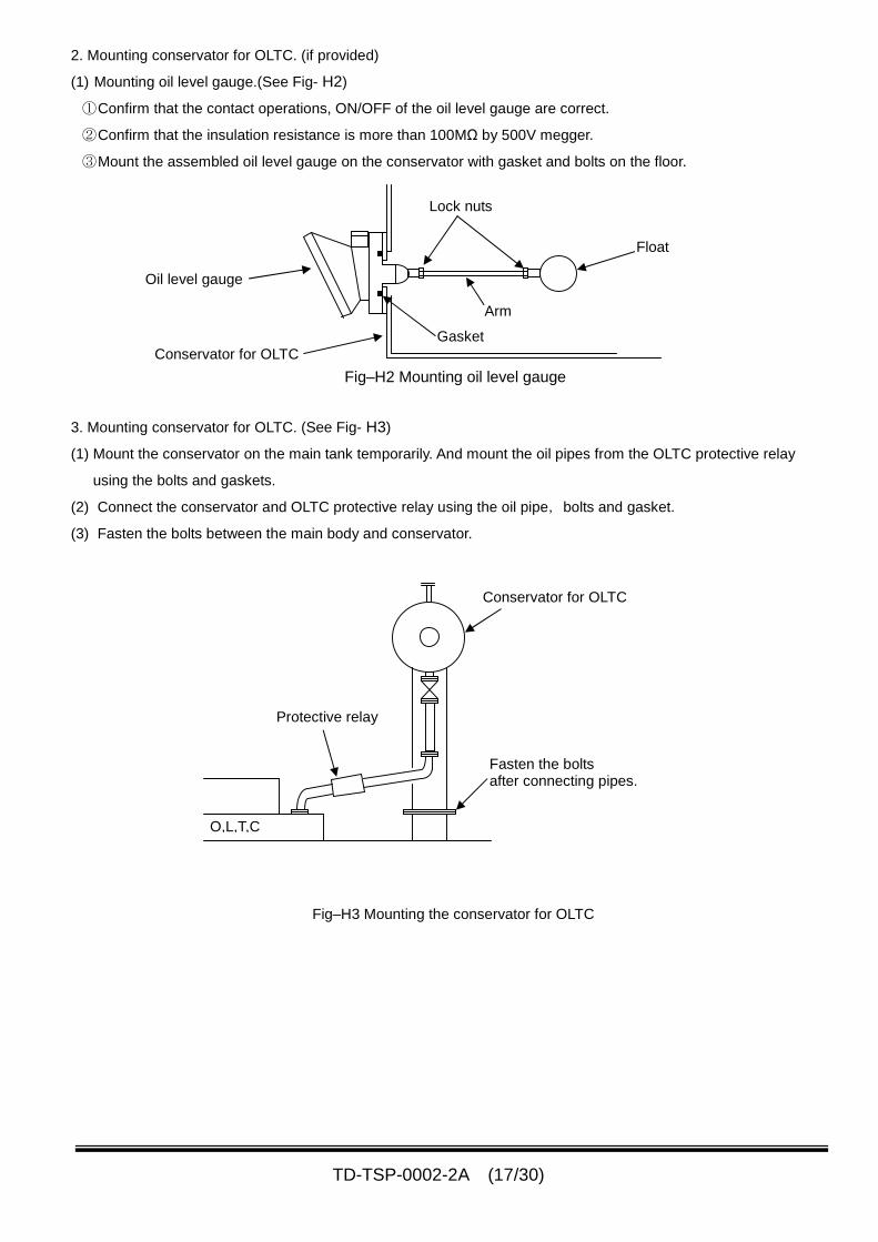
2. Mounting conservator for OLTC. (if provided)
(1) Mounting oil level gauge.(See Fig- H2)
①Confirm that the contact operations, ON/OFF of the oil level gauge are correct.
②Confirm that the insulation resistance is more than 100MΩ by 500V megger.
③Mount the assembled oil level gauge on the conservator with gasket and bolts on the floor.
3. Mounting conservator for OLTC. (See Fig- H3)
(1) Mount the conservator on the main tank temporarily. And mount the oil pipes from the OLTC protective relay
using the bolts and gaskets.
(2) Connect the conservator and OLTC protective relay using the oil pipe,bolts and gasket.
(3) Fasten the bolts between the main body and conservator.
Float
Lock nuts
Arm
Gasket
Oil level gauge
Conservator for OLTC
Fig–H2 Mounting oil level gauge
Protective relay
O,L,T,C
Fasten the boltsafter connecting pipes.
Conservator for OLTC
Fig–H3 Mounting the conservator for OLTC
TD-TSP-0002-2A (18/30)
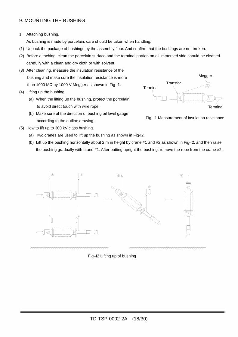
9. MOUNTING THE BUSHING
1. Attaching bushing.
As bushing is made by porcelain, care should be taken when handling.
(1) Unpack the package of bushings by the assembly floor. And confirm that the bushings are not broken.
(2) Before attaching, clean the porcelain surface and the terminal portion on oil immersed side should be cleaned
carefully with a clean and dry cloth or with solvent.
(3) After cleaning, measure the insulation resistance of the
bushing and make sure the insulation resistance is more
than 1000 MΩ by 1000 V Megger as shown in Fig-I1.
(4) Lifting up the bushing.
(a) When the lifting up the bushing, protect the porcelain
to avoid direct touch with wire rope.
(b) Make sure of the direction of bushing oil level gauge
according to the outline drawing.
(5) How to lift up to 300 kV class bushing.
(a) Two cranes are used to lift up the bushing as shown in Fig-I2.
(b) Lift up the bushing horizontally about 2 m in height by crane #1 and #2 as shown in Fig-I2, and then raise
the bushing gradually with crane #1. After putting upright the bushing, remove the rope from the crane #2.
Fig–I2 Lifting up of bushing
TransforTerminal
Terminal
Megger
Fig–I1 Measurement of insulation resistance
TD-TSP-0002-2A (19/30)
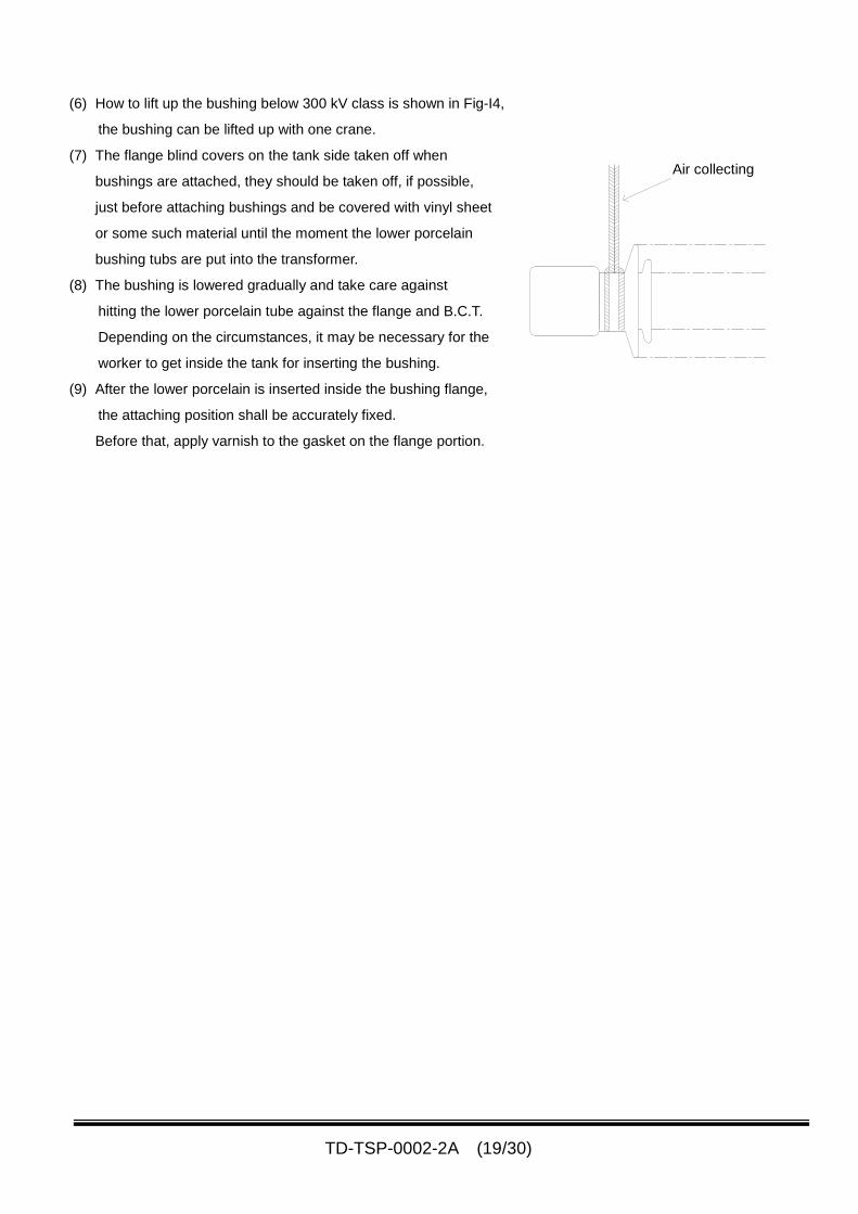
(6) How to lift up the bushing below 300 kV class is shown in Fig-I4,
the bushing can be lifted up with one crane.
(7) The flange blind covers on the tank side taken off when
bushings are attached, they should be taken off, if possible,
just before attaching bushings and be covered with vinyl sheet
or some such material until the moment the lower porcelain
bushing tubs are put into the transformer.
(8) The bushing is lowered gradually and take care against
hitting the lower porcelain tube against the flange and B.C.T.
Depending on the circumstances, it may be necessary for the
worker to get inside the tank for inserting the bushing.
(9) After the lower porcelain is inserted inside the bushing flange,
the attaching position shall be accurately fixed.
Before that, apply varnish to the gasket on the flange portion.
Air collecting
TD-TSP-0002-2A (20/30)
10. INTERNAL LEAD CONNECTION
1 Preparation and precautions for internal leads connection
(1)During internal job the insulation materials are exposed to open air. Therefore it is essential to do this work on
NON-rainy day.
(2) Oil level is lowered till bottom of the main body.
(3) Clean around the hand hole before opening the hand hole, and before starting the internal job.
(4) Never allow anyone to do the internal job before measuring the oxygen density of the main tank. The internal job
should be carried out after confirming that the oxygen density is shown more than 18%.
(5) Only nominated workers from the Shihlin Electric supervisor can work the internal job. And they should carry out
the internal job under supervision of the Shihlin Electric supervisor.
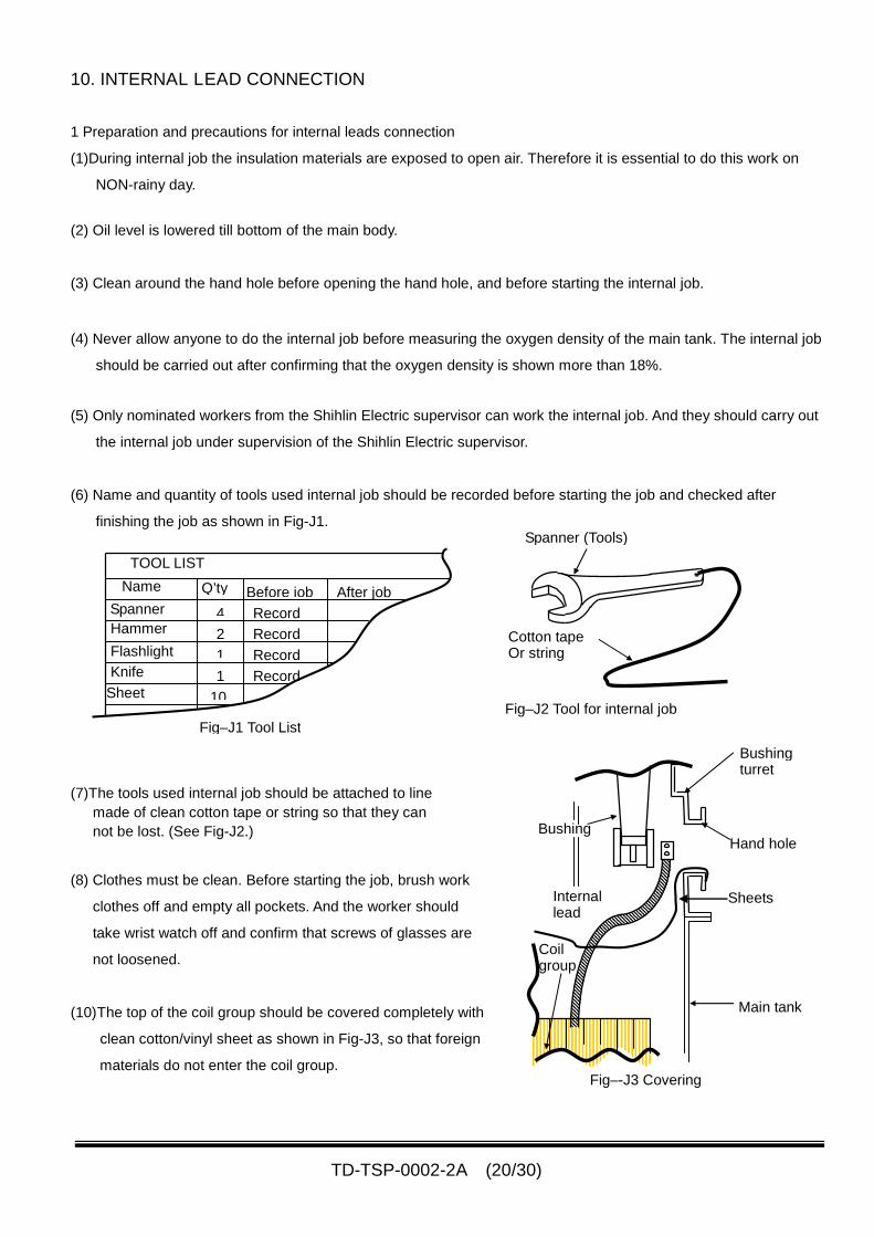
(6) Name and quantity of tools used internal job should be recorded before starting the job and checked after
finishing the job as shown in Fig-J1.
(7)The tools used internal job should be attached to line
made of clean cotton tape or string so that they can
not be lost. (See Fig-J2.)
(8) Clothes must be clean. Before starting the job, brush work
clothes off and empty all pockets. And the worker should
take wrist watch off and confirm that screws of glasses are
not loosened.
(10)The top of the coil group should be covered completely with
clean cotton/vinyl sheet as shown in Fig-J3, so that foreign
materials do not enter the coil group.
Fig–J1 Tool List
TOOL LIST
Name
Spanner
Hammer
Flashlight
Q’ty
4
2
1
1Knife
10
Before job After job
Record
Record
Record
RecordSheet
Fig–J2 Tool for internal job
Cotton tapeOr string
Spanner (Tools)
Fig–-J3 Covering
Internallead
Main tank
Coilgroup
Bushing
Bushingturret
Hand hole
Sheets
TD-TSP-0002-2A (21/30)
2. Connect all of the internal leads and the bushings according to the instructions of the Shihlin Electric supervisor.
(1)Connect the internal lead and the lower terminal of the bushing with the bolts and nuts.
(2)After finishing all of the internal lead connections, confirm that all of the fastening points are tightened correctly.
(3) Wrap the internal lead and the connection point according to the instruction of the Shihlin Electric supervisor.
(4)Bring all of the tools out and take all of the sheets out from the main body. And inspect following items;
① Insulation distances between the internal lead and the other internal lead, the internal lead and the main body
and the internal lead and core are maintained.
② Damaged point and dirty point is nothing.
(5)Close the hand hole and fill the main body with oil up to the level that the coil group is immersed.
TD-TSP-0002-2A (22/30)
11. FINAL OIL TREATMENT.
1. Carry out the oil leakage test in accordance with following procedure; (See Fig-K1.)
(1) Fill the main body with the oil up to level “2” of the conservator of the main body after opening V4.
(2) Remove the filter breather from the filter breather pipe for main body. And attach the valveV17、22, 23 and V24.
(V17, 22, 23 and V24 is used for installation work only.)
(3) Arrange the nitrogen gas cylinder, pressure regulator, compound gauge and the hoses.
(4) Apply pressure to the main body at 0.1-0.2kg/cm2
with the nitrogen gas and release the air from the conservator
through the V4 up to the oil is discharged from the V4.
〇Valve situations : Opened valve →V2,V4, V17, V22, V23 and V24.
Closed valve →V5,V6.
NOTE: Attend watchmen by the compound gauge and the V4 because the injection speed
of the nitrogen gas should be controlled by the pressure of the compound gauge.
And the V4 should be closed immediately when the oil is discharged.
(5)After removing the hose from the nitrogen gas cylinder and opening the V24, fill again the main body with the oil
up to the oil level is “6”.
(6) Apply pressure to the main body at 0.5kg/cm2
with the nitrogen gas and after closing the V24, jot down the
pressure and the oil temperature. And sit the main body this condition for 24Hours.
(7) Check the transformer for air leaks with soapy water and oil leaks
after 24hours from the time when the pressure was applied.
And then put all of the oil out from the main body.
NOTE: Don’t put the foreign materials into the main body.
Main body
Fig–K2
Pressure reliefdevice
Gasket
Fig–K1
Filter breatherpipe for main body
Conservatorfor main body
V6 V4
(Rubber bag)
V2 V5
Pressureregulator
Nitrogengas cylinder
V17
Oil level
Compoundgauge
Bypass Hose(Transparent vinyl hose)
Filter breatherpipe for OLTC
Conservatorfor OLTC
V22
V23
V24
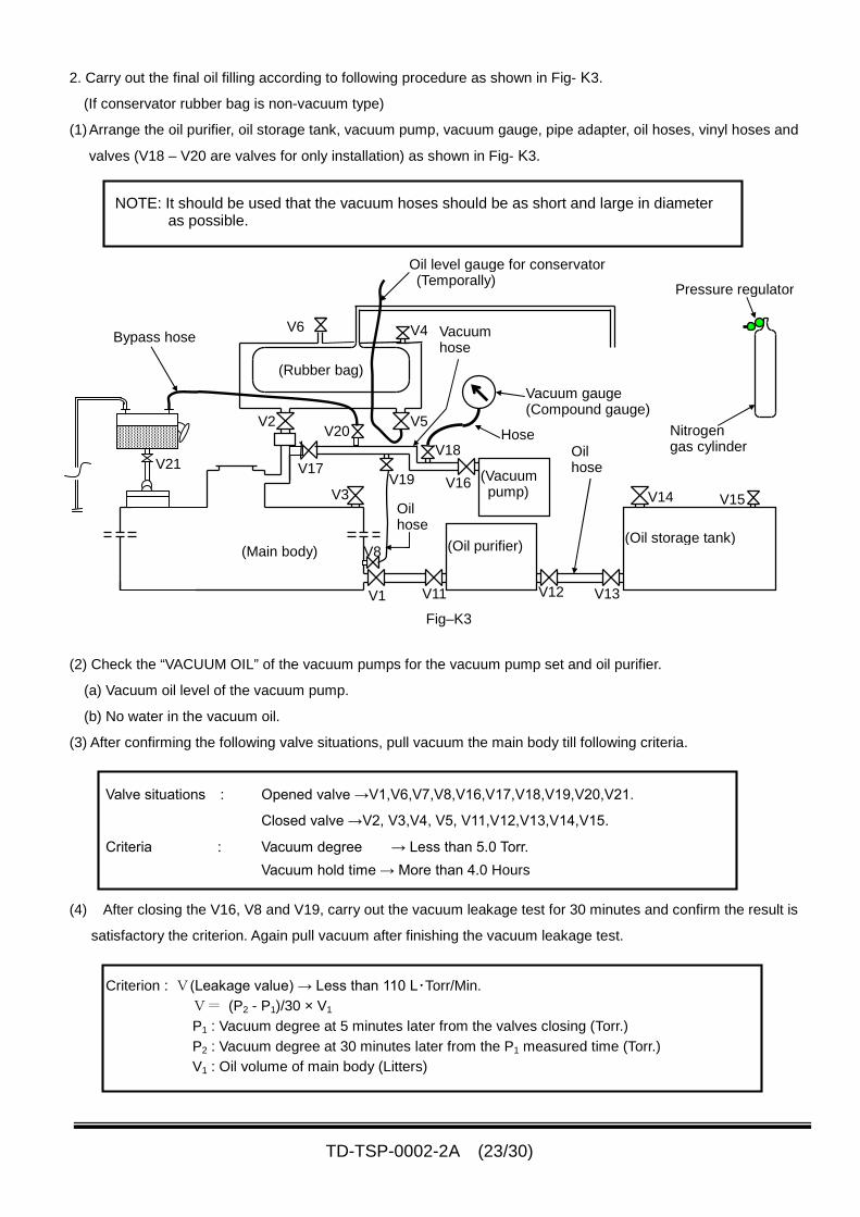
TD-TSP-0002-2A (23/30)
2. Carry out the final oil filling according to following procedure as shown in Fig- K3.
(If conservator rubber bag is non-vacuum type)
(1)Arrange the oil purifier, oil storage tank, vacuum pump, vacuum gauge, pipe adapter, oil hoses, vinyl hoses and
valves (V18 – V20 are valves for only installation) as shown in Fig- K3.
NOTE: It should be used that the vacuum hoses should be as short and large in diameteras possible.
(2) Check the “VACUUM OIL” of the vacuum pumps for the vacuum pump set and oil purifier.
(a) Vacuum oil level of the vacuum pump.
(b) No water in the vacuum oil.
(3) After confirming the following valve situations, pull vacuum the main body till following criteria.
Valve situations : Opened valve →V1,V6,V7,V8,V16,V17,V18,V19,V20,V21.
Closed valve →V2, V3,V4, V5, V11,V12,V13,V14,V15.
Criteria : Vacuum degree → Less than 5.0 Torr.
Vacuum hold time → More than 4.0 Hours
(4) After closing the V16, V8 and V19, carry out the vacuum leakage test for 30 minutes and confirm the result is
satisfactory the criterion. Again pull vacuum after finishing the vacuum leakage test.
Criterion : V(Leakage value) → Less than 110 L・Torr/Min.
V= (P2 - P1)/30 × V1
P1 : Vacuum degree at 5 minutes later from the valves closing (Torr.)
P2 : Vacuum degree at 30 minutes later from the P1 measured time (Torr.)
V1 : Oil volume of main body (Litters)
Fig–K3
Pressure regulator
Vacuumhose
Vacuum gauge(Compound gauge)
V4
(Rubber bag)
(Main body)
V2
V19
V1
V5Hose
Oilhose
Oilhose
Nitrogengas cylinder
(Vacuumpump)
(Oil storage tank)(Oil purifier)
V18
V16V14 V15
V13
V8
Bypass hose
V20
V21
V12
V3
V17
V11
V6
Oil level gauge for conservator(Temporally)
TD-TSP-0002-2A (24/30)
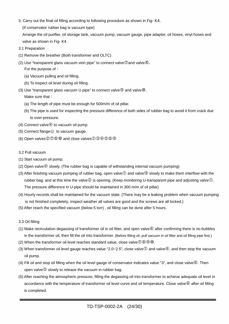
3. Carry out the final oil filling according to following procedure as shown in Fig- K4.
(If conservator rubber bag is vacuum type)
Arrange the oil purifier, oil storage tank, vacuum pump, vacuum gauge, pipe adapter, oil hoses, vinyl hoses and
valve as shown in Fig- K4.
3.1 Preparation
(1) Remove the breather (Both transformer and OLTC)
(2) Use “transparent glass vacuum vein pipe” to connect valveand valve.For the purpose of:
(a) Vacuum pulling and oil filling.
(b) To inspect oil level during oil filling.
(3) Use “transparent glass vacuum U pipe” to connect valve and valve.
Make sure that:
(a) The length of pipe must be enough for 500m/m of oil pillar.
(b) The pipe is used for inspecting the pressure difference of both sides of rubber bag to avoid it from crack due
to over-pressure.
(4) Connect valve to vacuum oil pump.
(5) Connect flange○12 to vacuum gauge.
(6) Open valves and close valves
3.2 Pull vacuum
(1) Start vacuum oil pump.
(2) Open valve slowly. (The rubber bag is capable of withstanding internal vacuum pumping)
(3) After finishing vacuum pumping of rubber bag, open valve and valve slowly to make them interflow with the
rubber bag, and at this time the valve is opening. (Keep monitoring U-transparent pipe and adjusting valve.
The pressure difference in U-pipe should be maintained in 300 m/m of oil pillar)
(4) Hourly records shall be maintained for the vacuum state. (There may be a leaking problem when vacuum pumping
is not finished completely, inspect weather all valves are good and the screws are all locked.)
(5) After reach the specified vacuum (below 5 torr) , oil filling can be done after 5 hours.
3.3 Oil filling
(1) Make recirculation degassing of transformer oil in oil fitter, and open valve after confirming there is no bubbles
in the transformer oil, then fill the oil into transformer. (Before filling oil, pull vacuum in oil filter and oil filling pipe first.)
(2) When the transformer oil level reaches standard value, close valve.
(3) When transformer oil level gauge reaches value “2.0~2.5”, close valve and valve, and then stop the vacuum
oil pump.
(4) Fill oil and stop oil filling when the oil level gauge of conservator indicates value “3”, and close valve. Then
open valve slowly to release the vacuum in rubber bag.
(5) After reaching the atmospheric pressure, filling the degassing oil into transformer to achieve adequate oil level in
accordance with the temperature of transformer oil level curve and oil temperature. Close valve after oil filling
is completed.
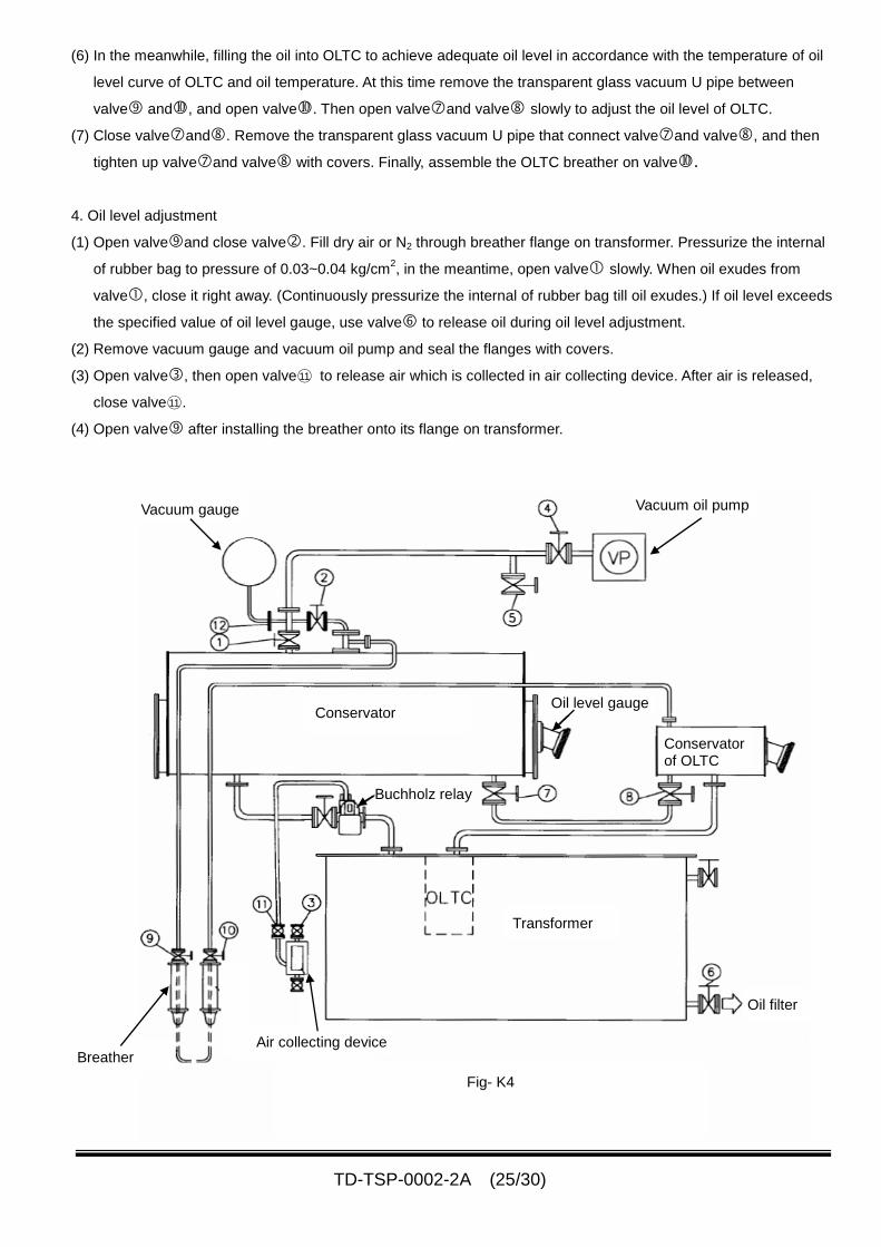
TD-TSP-0002-2A (25/30)
Fig- K4
Breather
Oil filter
Transformer
Conservatorof OLTC
Vacuum gauge Vacuum oil pump
ConservatorOil level gauge
Buchholz relay
Air collecting device
(6) In the meanwhile, filling the oil into OLTC to achieve adequate oil level in accordance with the temperature of oil
level curve of OLTC and oil temperature. At this time remove the transparent glass vacuum U pipe between
valve and, and open valve. Then open valveand valve slowly to adjust the oil level of OLTC.
(7) Close valveand. Remove the transparent glass vacuum U pipe that connect valveand valve, and then
tighten up valveand valve with covers. Finally, assemble the OLTC breather on valve.
4. Oil level adjustment
(1) Open valveand close valve. Fill dry air or N2 through breather flange on transformer. Pressurize the internal
of rubber bag to pressure of 0.03~0.04 kg/cm2, in the meantime, open valve slowly. When oil exudes from
valve, close it right away. (Continuously pressurize the internal of rubber bag till oil exudes.) If oil level exceeds
the specified value of oil level gauge, use valve to release oil during oil level adjustment.
(2) Remove vacuum gauge and vacuum oil pump and seal the flanges with covers.
(3) Open valve, then open valve○11 to release air which is collected in air collecting device. After air is released,
close valve○11 .
(4) Open valve after installing the breather onto its flange on transformer.
TD-TSP-0002-2A (26/30)
12. INSPECTION.
1. Electrical test
A number of tests can be used to determine the condition of the transformer.
The most typical tests are as follows.
1-1. Insulation resistance
The insulation resistance of winding to ground measured by more than 1000V megger.
As the insulation resistance changes according to the temperature and humidity, it is necessary to measure
and record the oil temperature at that time.
1-2. Checking protective circuit
(1) Measure the insulation resistance of the protective circuits and their devices. And be sure that the insulation
resistance is more than 10 MΩ.
(2) Check the protective devices operations are correct in accordance with the sequence diagram.
2. General inspection. Check following items ;
À Oil and gas leakage.
Á Bolt connection.
 Discoloration.
à Abnormal noise and vibration of fan.
Ä Direction of rotary of fans.
Å Reading and setting value of protective relays
Æ All valves situations. (Opened or closed.).
TD-TSP-0002-2A (27/30)
13. TOUCH-UP PAINTING.
This item applies to the external surface painting of the main tank or the parts which are damaged or welded
during transportation and erection.
1 Treatment for under coating
(1)Damaged portion
(a)Wash away the oil, grease, dirt and dust using the organic solvent for removing fat and wipe out by the waste
rags, then dry it up.
(b)Polish the surface to be painted using emery cloth #200 - #320, and then clean the surface again.
(c)After cleaning, mix and stir the wash primer base and additives (Weight ratio 8 VS 2), add the thinner of 10-20%
(Weight percent) for arrangement of the viscosity of necessary.
(d)Paint the materials by the brush uniformly.
(e)Drying time ; Summer season (20℃ or more) : Natural drying more than 2-3 hours.
Winter season (Less than 20℃) : Natural drying more than 4-5 hours.
(2) Welding portion
(a)Remove the paint film burned by the welding using the wire brush and steel chisel.
(b)Remove the scale and rust on the welded portion using the wire brush and steel chisel.
(c)Wash away the oil, grease, dirt and dust using the organic solvent for removing fat and wipe out by the waste
rags, then dry it up.
(d)Polish the surface to be painted using emery cloth #200 - #320, and then clean the surface again.
(e)After cleaning, mix and stir the wash primer base and additives (Weight ratio 8 VS 2), add the thinner of 10-20%
(Weight percent) for arrangement of the viscosity of necessary.
(f)Paint the materials by the brush uniformly.
(g)Drying time: Summer season (20℃ or more) : Natural drying more than 2-3 hours.
Winter season (Less than 20℃) : Natural drying more than 4-5 hours.
2 Finish painting (General, acidity and oceanic environment.)
(1) Pain the material with the brush using the phthalic acid resin enamel which is arranged the viscosity.
(2) Drying time;
Summer season (20℃ or more) : Natural drying more than 3-4 hours.
Winter season (Less than 20℃) : Natural drying more than 6-8 hours.
3 Inspections
Check the painted condition of the surface.
(1) Lack of uniformity of paint
(2) Beauty of paint surface
(3) Paint drops
(4) Unpainted parts and section
TD-TSP-0002-2A (28/30)
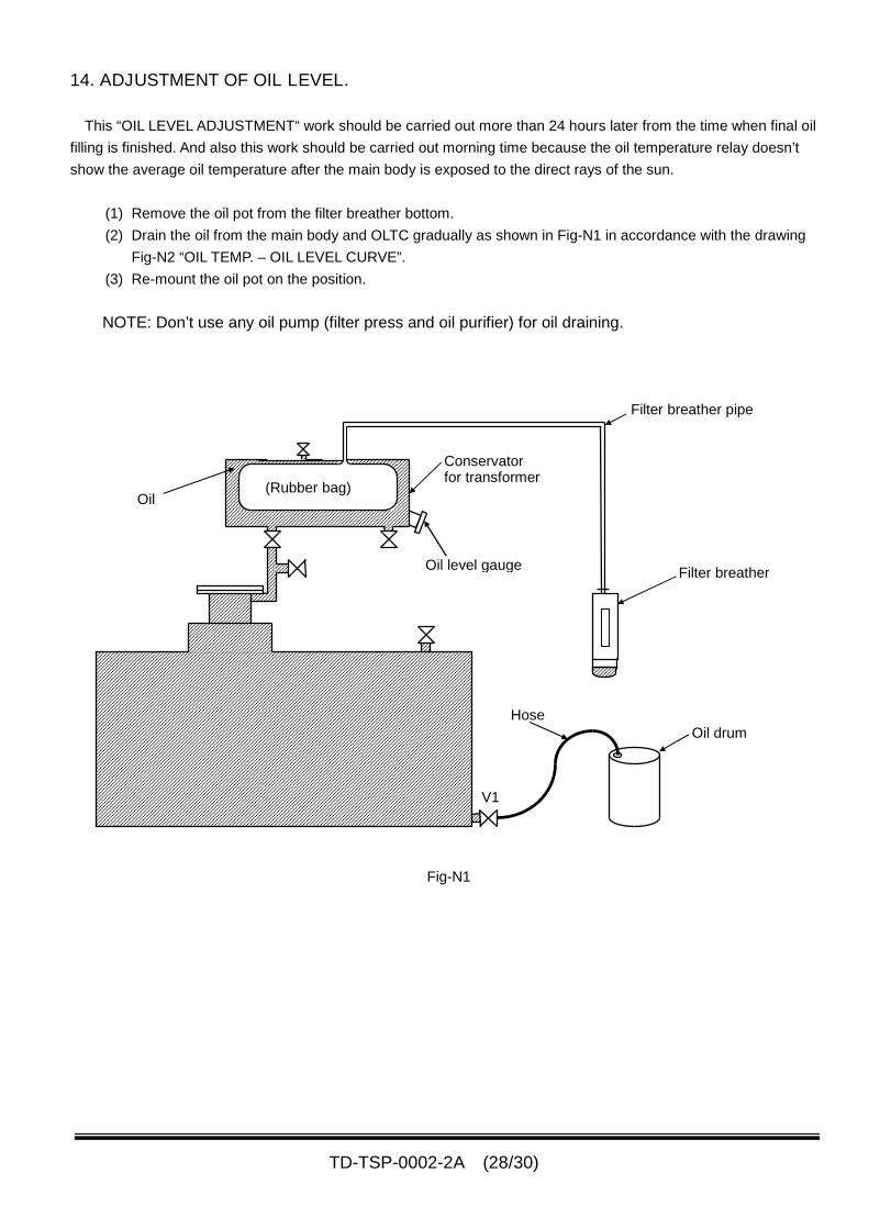
14. ADJUSTMENT OF OIL LEVEL.
This “OIL LEVEL ADJUSTMENT“ work should be carried out more than 24 hours later from the time when final oil
filling is finished. And also this work should be carried out morning time because the oil temperature relay doesn’t
show the average oil temperature after the main body is exposed to the direct rays of the sun.
(1) Remove the oil pot from the filter breather bottom.
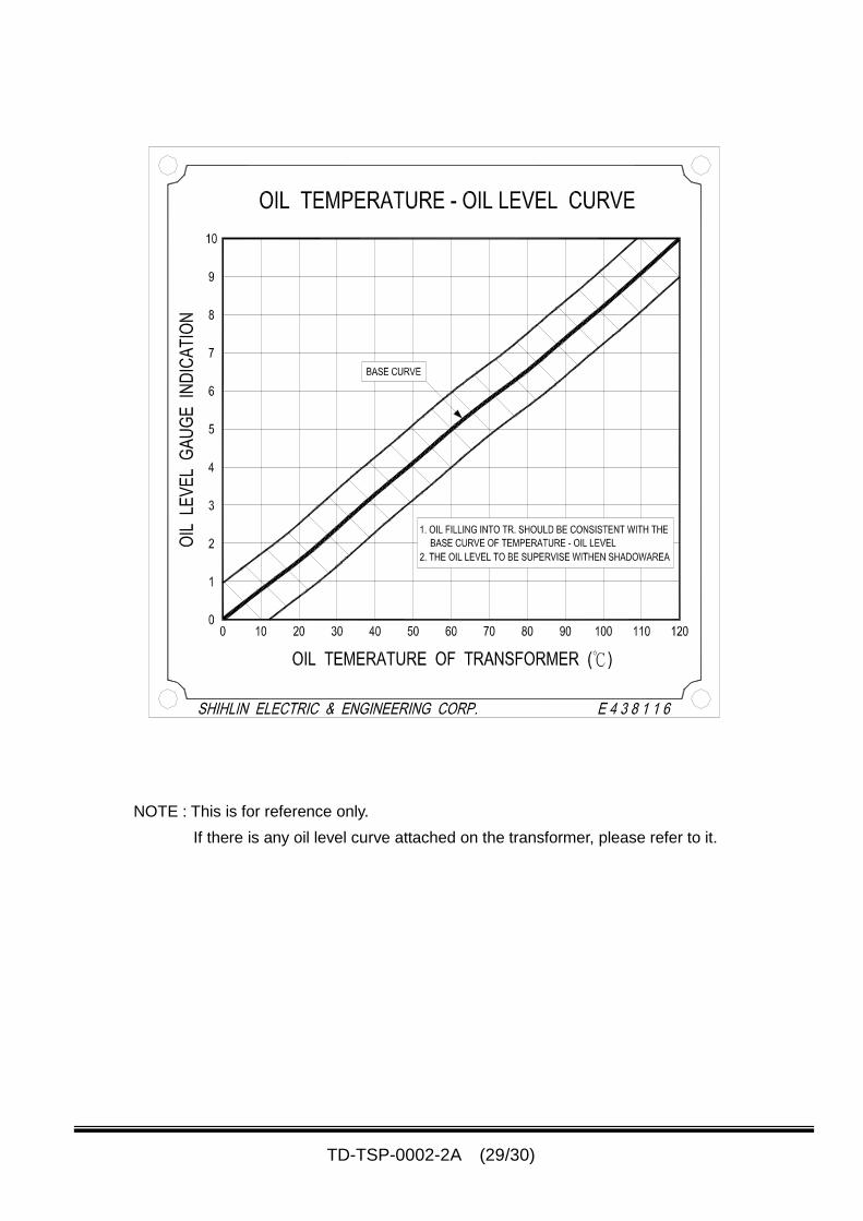
(2) Drain the oil from the main body and OLTC gradually as shown in Fig-N1 in accordance with the drawing
Fig-N2 “OIL TEMP. – OIL LEVEL CURVE”.
(3) Re-mount the oil pot on the position.
NOTE: Don’t use any oil pump (filter press and oil purifier) for oil draining.
Filter breather pipe
Filter breather
Conservatorfor transformer
(Rubber bag)
V1
Hose
Oil level gauge
Oil drum
Oil
Fig-N1
TD-TSP-0002-2A (29/30)
NOTE : This is for reference only.
If there is any oil level curve attached on the transformer, please refer to it.
TD-TSP-0002-2A (30/30)
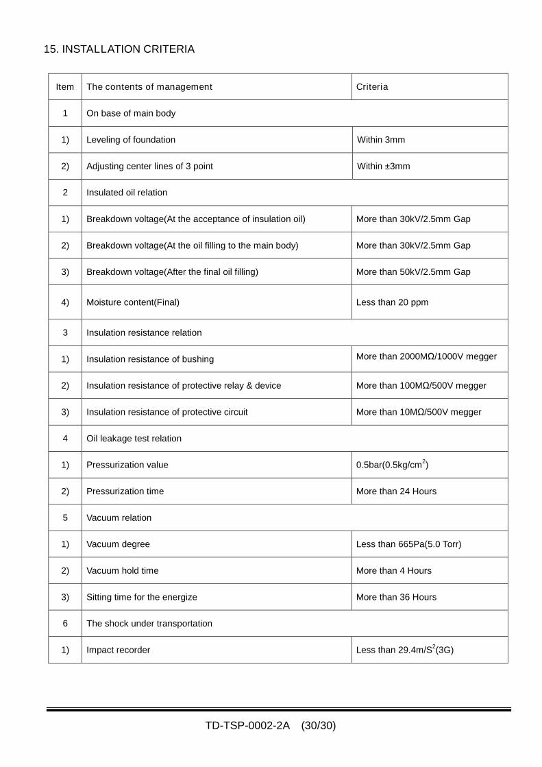
15. INSTALLATION CRITERIA
Item The contents of management Criteria
1 On base of main body
1) Leveling of foundation Within 3mm
2) Adjusting center lines of 3 point Within ±3mm
2 Insulated oil relation
1) Breakdown voltage(At the acceptance of insulation oil) More than 30kV/2.5mm Gap
2) Breakdown voltage(At the oil filling to the main body) More than 30kV/2.5mm Gap
3) Breakdown voltage(After the final oil filling) More than 50kV/2.5mm Gap
4) Moisture content(Final) Less than 20 ppm
3 Insulation resistance relation
1) Insulation resistance of bushing More than 2000MΩ/1000V megger
2) Insulation resistance of protective relay & device More than 100MΩ/500V megger
3) Insulation resistance of protective circuit More than 10MΩ/500V megger
4 Oil leakage test relation
1) Pressurization value 0.5bar(0.5kg/cm2)
2) Pressurization time More than 24 Hours
5 Vacuum relation
1) Vacuum degree Less than 665Pa(5.0 Torr)
2) Vacuum hold time More than 4 Hours
3) Sitting time for the energize More than 36 Hours
6 The shock under transportation
1) Impact recorder Less than 29.4m/S2(3G)