Embed Size (px)
Citation preview

atib.com I-D02-01-29 - Rev.2
INSTRUCTIONS MANUAL FOR USE DOUBLE FORK POSITIONER TYPE 917 TRIPLE FORK POSITIONER TYPE 918

Pag. 1 di 37
INDEX DOUBLE FORK POSITIONER TYPE 917 TRIPLE FORK POSITIONER TYPE 918
1 SAFETY RULES ............................................................................................................................... 3
2 INTRODUCTION ............................................................................................................................... 4
2.1 Use and upkeep of this manual ......................................................................................... 4
2.2 Description of equipment ................................................................................................... 5
3 INSTALLATION ................................................................................................................................ 9
3.1 Installation ......................................................................................................................... 10
3.1.1 Attachment Installation - TYPE 917.T2/T4 and 918.T ................................................10
3.1.2 Attachment Installation – TYPE 917.2/4 e 918 ...........................................................15
3.2 Fork Installation ................................................................................................................ 18
4 HYDRAULIC SYSTEM .................................................................................................................... 19
4.1 HYDRAULIC SYSTEM – TYPE 917.T2/T4 and 918.T ....................................................... 19
4.2 Hydraulic System – TYPE 917.2/4 and 918 ...................................................................... 20
5 USE RULES .................................................................................................................................... 21
6 PERIODIC MAINTENANCE ............................................................................................................ 24
6.1 Maintenance Every 100 Hours ......................................................................................... 24
6.2 Maintenance Every 300 Hours ......................................................................................... 24
6.3 Maintenance Every 1000 Hours ....................................................................................... 25
6.4 Maintenance Every 2000 Hours ....................................................................................... 25
WARNING
READ THIS MANUAL VERY CAREFULLY BEFORE STARTING-UP THE MACHINE

Pag. 2 di 37
7 DISASSEMBLY PROCEDURE ....................................................................................................... 26
7.1 Disassembly attachments from forklift ........................................................................... 26
7.2 Forks disassembly ............................................................................................................ 27
7.3 Fork cylinders removal from attachments ...................................................................... 28
7.3.1 Disassembly and reassembly of the fork cylinders ..................................................29
7.4 Gas spring removal from attachment .............................................................................. 30
7.4.1 Disassembly and reassembly of the gas spring .......................................................32
7.5 SLS cylinder removal from attachment ........................................................................... 33
7.5.1 Disassembly and reassembly SLS cylinder ..............................................................34
8 BREAKDOWNS AND SOLUTIONS ................................................................................................ 35
8.1 Breakdowns and solution................................................................................................. 35
8.2 Lubrication ........................................................................................................................ 36

1 SAFETY RULES
Pag. 3 di 37
1 SAFETY RULES
Don’t carry passengers Don’t cross the mast
Don’t pass under the load
MARCH

2 INTRODUCTION
Pag. 4 di 37
2 INTRODUCTION
2.1 Use and upkeep of this manual
This “User Manual” (hereinafter referred to as Manual) is supplied together with the A.T.I.B. –
DOUBLE FORK POSITIONER TYPE 917 - TRIPLE FORK POSITIONER TYPE 918 pursuant the
CE DIRECTIVE 2006/42/CE date 17/05/2006 and amendments.
The information contained here are imperative for the correct use of the attachment and must
be known by the personnel who install, use, maintain and repair it.
This manual must be considered integral part of the attachment and must be kept as long as the
attachment is in use on any machine in an accessible place, protected, dry and available for
immediate consultation.
Should this manual be lost, the operator can apply for the supply of further copies from the
manufacturer.
The manufacturer is not liable in cases of:
- improper use of the attachment;
- use by untrained personnel;
- use contrary to current national and international laws;
- lack of recommended maintenance;
- non authorised modifications and repairs;
- use of non original spare parts or parts for other models;
- failure to adhere, either totally or partially, to these instructions;
- exceptional circumstances.
The manufacturer reserves the right to modify this Manual without notice and without the obligation to update the copies previously distributed.
The Nominal Capacity of the forklift / Equipment combination is established by the original manufacturer of the forklift and may be lower than that indicated on the identification plate. Consult the plate of the forklift (Directive 2006/42 / EC).

2 INTRODUCTION
Pag. 5 di 37
2.2 Description of equipment
TYPE 917.T2 TYPE 917.T4
TYPE 917.2 TYPE 917.4

2 INTRODUCTION
Pag. 6 di 37
TYPE 918.T
TYPE 918
2 INTRODUCTION
Pag. 7 di 37
All the A.T.I.B. – DOUBLE FORK POSITIONER TYPE 917 - TRIPLE FORK POSITIONER TYPE
918 equipment is identified by means of a sticky identification label (Tab. 1) position of
identification label on equipment (Picture 1; for all types, the position of the identification plate
is the same as shown in the figure), always refer to the serial number.
1. TYPE 8. NOMINAL CAPACITY kg/mm 11. MAX. TORQUE daN m
2. CODE 9. CLAMPING CAPACITY kg/mm
3. SERIAL N°
4. YEAR OF MANUFACTURE 10. MAX. OPERATING PRESSURE
bar A.T.I.B. S.r.l. Via Quinzanese snc, 25020 Dello (BS) - ITALIA +39 030/9771711 [email protected] - atib.com
5. WEIGHT
6. THICKNESS WARNING: RESPECT THE RATED CAPACITY OF TRUCK AND ATTACHMENT COMBINED 7. CENTER OF GRAVITY
Tab. 1
Picture 1
POSITION OF IDENTIFICATION LABEL

2 INTRODUCTION
Pag. 8 di 37
1. TYPE
It identifies the model of the equipment as shown in the catalogue.
2. CODE
It identifies the equipment order code.
3. SERIAL N°
It progressively identifies the individual equipment.
The series number has been stamped should the tag go missing or be damaged. Always refer
to the series number for any kind of information.
4. YEAR OF CONSTRUCTION
It indicates the year of construction.
5. WEIGHT
It indicates the Q weight of the equipment in kg.
6. THICKNESS
It indicates the thickness of the equipment in mm.
7. CENTER OF GRAVITY
It indicates the distance in mm of the equipment CG center of gravity from the fork holding
plate table.
8. NOMINAL CAPACITY
It indicates the maximum P load applicable to the hoisting equipment and the maximum CC
barycentric distance of the load itself.
9. CLAMPING CAPACITY
Not applicable to this equipment.
10. MAX OPERATING PRESSURE
It indicates the maximum pressure applicable to the equipment.
11. MAX COUPLE
Not applicable to this equipment.
The A.T.I.B. – DOUBLE FORK POSITIONER TYPE 917 - TRIPLE FORK POSITIONER TYPE 918
were planned and built to allow the transportation and, if requested, the side shifting, of 1, 2 or
3 pallets with the possibility to modify the opening range of the internal and external Forks of
the Attachment itself.
T = Sideshift semi-integrated
917.2/.T2 = To transport of 1 o 2 pallets.
917.4/.T4 = To transport of 1-2-4 pallets (longer forks)
This attachment is designed to be applied to the fork carriage of forklift trucks and connected
with hydraulic circuit via to the hydraulic distributor.
Safety components are manufactured to ISO Standard 2328.

3 INSTALLATION
Pag. 9 di 37
3 INSTALLATION
Verify the nominal capacity of equipment
To check the nominal capacity of equipment, consult the identification label (Tab. 1 pag.7).
Check operation pressure and flow rate of oil
A.T.I.B. advises to respect the hydraulic flow rates and operating pressures shown in Tab. 2, in
order to optimize the operation of the equipment and avoid problems during the work or
commissioning phases. The values are indicative and may vary depending on the equipment.
TYPE and ISO PORTATA (l/mm) Max. operating
pressure (Bar) Min. Max. recommended 917.T2 ALL [II & III] 30/10 50/20 45/15 200
917.T4 ISO III 30/10 50/20 45/15 200
917.T4 ISO IV 30/15 50/25 45/20 200
917.2 ALL [II & III] 30 50 45 200
917.4 ISO III 30 50 45 200
917.4 ISO IV 30 50 45 200
918.T ALL [III] 30/15 50/25 45/20 200
918 ALL [III] 30 50 45 200 Tab. 2
values in bold refer to sideshift.
The forklift manufacturer is responsible for calculating the residual capacity of the forklift /equipment assembly.
WARNING!!
RESPECT THE MAXIMUM WORKING PRESSURES INDICATED
WARNING
Make sure that the operator of the forklift is aware of the maximum capacity of the attachments, so as NOT to pose a danger to himself and to the people who work in his vicinity.

3 INSTALLATION
Pag. 10 di 37
3.1 Installation
3.1.1 Attachment Installation - TYPE 917.T2/T4 and 918.T
1. Before installation, verify the condition of the fork carriage,
ensuring that it is not deformed.
2. Also make sure that the profiles of the fork holding plate are not deformed, in order to allow
a good coupling with the equipment.
3. Check the condition of the pipes, replacing those that are in a bad condition.
NOTE: although in the following figures only the 917.T2 type is represented, the installation
method is the same also for 917.T4 and 918.T.
4. Remove the two pins, with the relative snap rings, which lock the semi-integral sideshift
cylinder (Picture 2).
TYPE 917.T2/T4 E 918.T
Picture 2

3 INSTALLATION
Pag. 11 di 37
5. After the shifting cylinder has been removed, manually take the double hook A, and place it
on the upper profile of the fork carriage, placing the centring tooth C into the central notch
(Picture 3).
Picture 3
3 INSTALLATION
Pag. 12 di 37
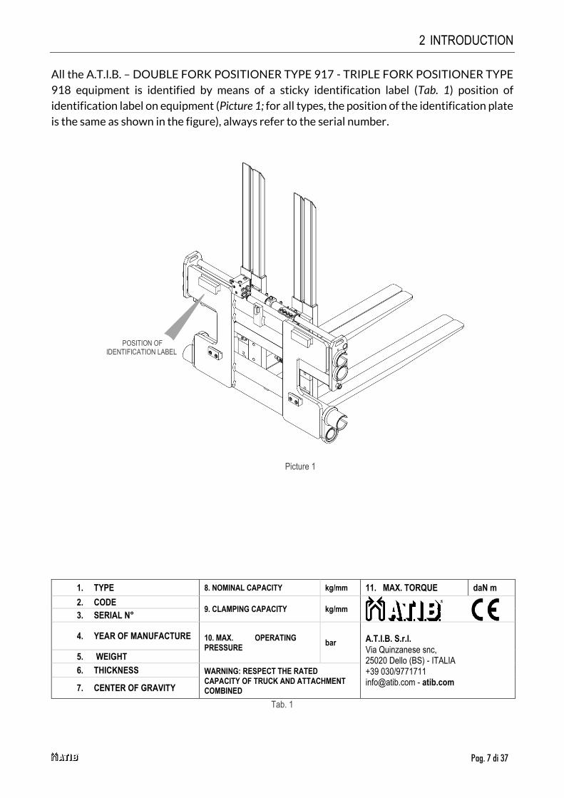
6. Unscrew the lower hooks of equipment and lubricate the slide (Picture 4).
7. For handling, use belts or chains appropriately sized for the weight of the equipment,
indicated on the identification plate (Picture 1 and Tab. 1 pag.7).
8. with an overhead crane or with a hoist of sufficient capacity hook the attachment on the
double hook, taking care to position the equipment correctly (Picture 5).
Picture 4
Picture 5
3 INSTALLATION
Pag. 13 di 37
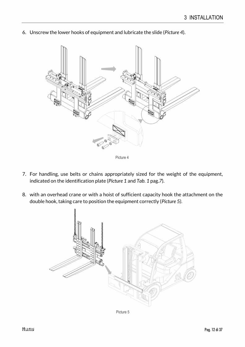
9. Reposition the SLS cylinder using the previously removed pins and elastic rings (Picture 6).
Picture 6

3 INSTALLATION
Pag. 14 di 37
10. Screw the two bottom hooks G with bolts so that the attachment is safely mounted on the
fork carriage P (with a tolerance max. 1,5mm, Picture 7), reaching to the following torques
Tab. 3.
11. Lubricate the contact parts.
12. Connect the hydraulic circuit; making sure that the operating pressure of the pipes is higher
than or equal to that indicated on the identification label (Picture 1 and Tab. 1 pag.7).
ISO 2328 THREAD TORQUE
ISO II M12 90 Nm
ISO III M14 140 Nm
ISO IV M16 220 Nm Tab. 3
Picture 7
3 INSTALLATION
Pag. 15 di 37
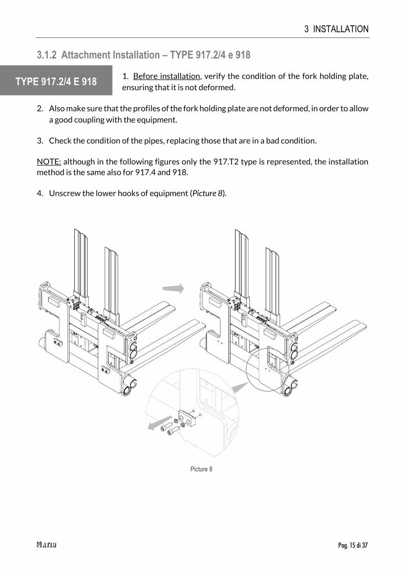
3.1.2 Attachment Installation – TYPE 917.2/4 e 918
1. Before installation, verify the condition of the fork holding plate,
ensuring that it is not deformed.
2. Also make sure that the profiles of the fork holding plate are not deformed, in order to allow
a good coupling with the equipment.
3. Check the condition of the pipes, replacing those that are in a bad condition.
NOTE: although in the following figures only the 917.T2 type is represented, the installation
method is the same also for 917.4 and 918.
4. Unscrew the lower hooks of equipment (Picture 8).
TYPE 917.2/4 E 918
Picture 8

3 INSTALLATION
Pag. 16 di 37
5. For handling, use belts or chains appropriately sized for the weight of the equipment,
indicated on the identification plate (Picture 1 and Tab. 1 pag.7).
6. with an overhead crane or with a hoist of sufficient capacity hook the attachment to the
fork carriage, placing the centring tooth C into the central notch (Picture 9).
Picture 9

3 INSTALLATION
Pag. 17 di 37
7. Screw the two bottom hooks G with bolts so that the attachment is safely mounted on the
fork carriage P (with a tolerance max. 1,5mm, Picture 10), reaching to the following torques
Tab. 4.
8. Lubricate the contact parts.
9. Connect the hydraulic circuit; making sure that the operating pressure of the pipes is higher
than or equal to that indicated on the identification label (Picture 1 and Tab. 1 pag.7).
ISO 2328 THREAD TORQUE
ISO II M12 90 Nm
ISO III M14 140 Nm
ISO IV M16 220 Nm
Tab. 4
Picture 10

3 INSTALLATION
Pag. 18 di 37
3.2 Fork Installation
NOTE: the forks are the same for all type of attachments, therefore the installation procedure
is the same.
1. Apply the forks on fork holder, screw the relative screws (Picture 11).
2. Check that the forks are locked correctly (Picture 12).
NOTE: the torque of screws (M16) of fork is 170Nm.
Picture 12
Picture 11
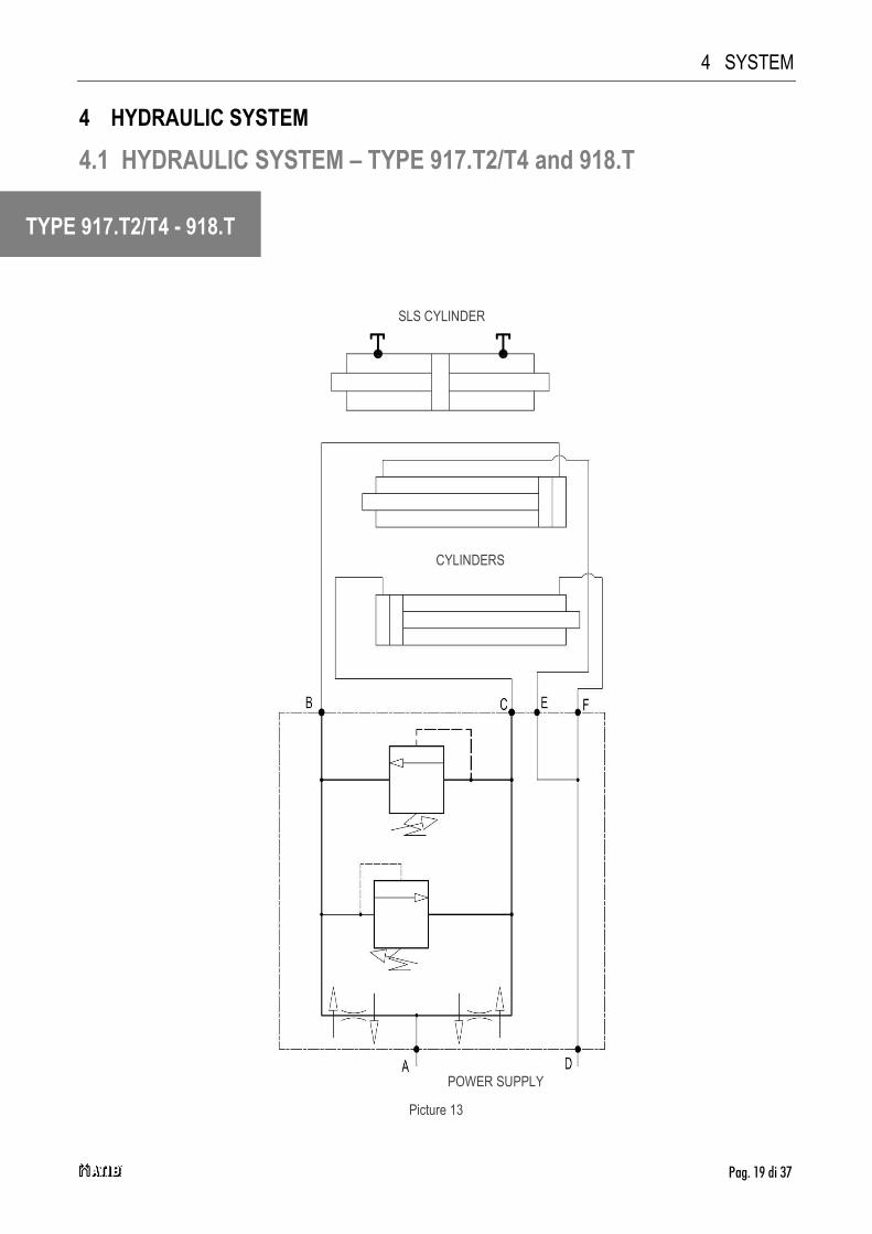
4 SYSTEM
Pag. 19 di 37
4 HYDRAULIC SYSTEM
4.1 HYDRAULIC SYSTEM – TYPE 917.T2/T4 and 918.T
TYPE 917.T2/T4 - 918.T
Picture 13
CYLINDERS
POWER SUPPLY
SLS CYLINDER

4 SYSTEM
Pag. 20 di 37
4.2 Hydraulic System – TYPE 917.2/4 and 918
TYPE 917.2/4 - 918
CYLINDERS
POWER SUPPLY
Picture 14
5 RULES
Pag. 21 di 37
5 USE RULES
Before using the equipment, check the tightness of the pipes and the correctness of assembly and
connection by performing about ten preliminary operations.
When using the equipment, it is necessary to follow the instructions listed below:
1. Observe the capacity limits of the equipment.
2. Do not use the equipment when people or animals are within the range of action of the
forklift.
3. Do not try to lift loads by clamping them between the two forks.
4. Do not try to move loads sideways by sliding them on the ground.
5. Do not exceed the maximum pressure value indicated on the identification plate.
6. Operate the equipment from the driver's seat of the forklift by a single operator.
7. Act gently on the translation control lever, avoiding water hammer as much as possible.
8. Any operation relating to installation, use and maintenance must be performed by
specialized personnel equipped with appropriate equipment for the type of intervention
to be carried out.
9. Carry out maintenance and / or repair operations with the forklift stopped and with the
hydraulic circuit not active, using suitable protective equipment (gloves, safety shoes,
etc).
10. Operate the piston rods only when they are correctly mounted on the equipment;
Otherwise, the piston rods could be violently ejected by the oil pressure.
The considered acoustic pressure level is lower than 70 dB (A).
Should the equipment be subject to slight errors in the movement synchronism between the
two forks, these movement differences, which will add up in time, will have to be annulled by
an operator.
It will be sufficient for the operator to keep one of the two forks at the opening or closing end
stroke, for the necessary time it will take for the other fork to recuperate the difference in
movement accumulated.

5 RULES
Pag. 22 di 37
Every ATIB attachments are projected and constructed according to a load positioned (as
regards its centre of gravity) at a certain distance from vertical part of the fork.
If you need to increase the distance of the center of gravity as regards vertical part of the
fork you have to reduce the weight of the load.
In this occasion, we suggest to control the chart (Picture 15) where, according to the
increase of the centre of gravity (x-axis) there is a load reduction multiplying factor (y-axis).
The multiplying factor, obtained based on desired load centre position, will be multiplied with
nominal capacity of the equipment. The result of this multiplication will be actual capacity of
the attachment.
Continuous line is for equipment with load center at 500 mm.
Dotted line is for equipment with load center at 600 mm.
NOTE - This calculation is valid only for “stable” load, in case of movement of liquid material please contact the
producer.
Picture 15
Residual capacity (pair of forks)
Fat
tore
Mol
tiplic
ativ
o
Center of gravity (mm)
5 RULES
Pag. 23 di 37
The affordable stroke can compromise the stability of the forklift.
To check the nominal capacity of the combination forklift – attachment ask the
producer of the forklift.
The condition of the soil, the quickness of the movement of the load and the lifting
height can affect the hold of the load and must be taken into consideration as
regards specific occasions.
Side shifting movement is forbidden in movement.
Side shifting movement in condition of lifted mast is permitted only to bring back
the load at the center of the mast.
Nominal capacity of the combination forklift – attachment is established by the producer of the
forklift and can be lower than the one indicated on the identification label of the attachment.
Check label of the forklift (Directive 2006/42/CE).

6 PERIODIC MAINTENANCE
Pag. 24 di 37
6 PERIODIC MAINTENANCE
Failure to adhere to the norms and established times for maintenance operations, will be
detrimental to the good functioning of the equipment and will annul the guarantee conditions.
All maintenance operations must be carried out with the forklift motionless and the hydraulic
circuit not activated, perimeter the entire maintenance area, using the necessary protective devices
and, if it is necessary to disassemble the cylinders, always using a tray or container to recover the
oil still present in the cylinder itself.
To avoid problems regarding the use of the equipment, A.T.I.B recommends changing the
hydraulic oil and its filters regularly and trying to keep the system as clean as possible during
maintenance operations.
6.1 Maintenance Every 100 Hours
1. Check the conditions of the hydraulic connections (pipes and fittings), replacing, if
necessary, the worn parts.
2. Check the tightening torque of the bolts of the lower sealing hooks of the equipment,
verifying that it is as indicated in Tab. 3 (pag. 14) and Tab. 4 (pag. 17), if necessary, intervene
on the tightening of the screws that support them.
3. Check the clearance between the lower part of the fork holder plate and the lower hooks
of the equipment, verifying that it is as indicated in Picture 7 (pag. 14) and Picture 10 (pag.
17), if necessary, intervene on the tightening of the screws that support them.
4. Check the correct tightening of the locking screws of the fork stops. If necessary, intervene
on the tightening.
5. Clean and lubricate all sliding parts (Picture 25 and Picture 26 a pag. 36).
6.2 Maintenance Every 300 Hours
1. Check the condition of upper and lower sliding devices if an excessively worn component is
found, it is recommended to replace the entire assembly of the component in question.
2. Also carry out the operations listed in the previous point (Point 6.1).
WARNING!!!
The hydraulic parts can be very hot. Use adequate protections.
Beware of any leaks. Oil under high pressure can damage the eyes and skin. Always wear
protective goggles on the sides as well.
Never remove valves, hoses or other potentially pressurized parts when it is active.

6 PERIODIC MAINTENANCE
Pag. 25 di 37
6.3 Maintenance Every 1000 Hours
1. Check the condition of upper and lower sliding devices if an excessively worn component is
found, it is recommended to replace the entire assembly of the component in question.
2. Check the state of the sliding axis, making sure it is not scratched or deformed in any way.
3. Also carry out the operations listed in the previous points (Point 6.1 e 6.2 pag. 24).
6.4 Maintenance Every 2000 Hours
1. Proceed with a thorough inspection of the equipment; this, possibly, must be performed by
qualified personnel, able to identify any problems that could compromise the safety and
efficiency of use of the equipment. The defects that can be found can be many:
- Check the condition of all equipment components (cylinders, hooks, gaskets, fittings,
grease nipples, etc.), verifying that their conditions are optimal and, if there are worn
components, proceed with their replacement / repair.
- Check the condition of the sliding and working surfaces and proceed with their
replacement / repair if they are damaged.
For further possible problems (and relative solutions) refer also to Tab. 5 pag.35.
2. Disassemble the cylinders and check the condition of the rods and seals, if there is a
damaged or excessively worn seal, it is always recommended to replace the entire assembly
seals.
3. Replace the seals even in the event of oil leaks and the rods if scratched (the cylinders must
always be tested inserted in the equipment in order to avoid the sudden expulsion of the
rods).
4. Also carry out the operations listed in the previous points (Point 6.1, and Points 6.2, 6.3 at
pag. 24).
Please Note: Intensify interventions in case of use in particularly severe conditions.

7 DISASSEMBLY PROCEDURE
Pag. 26 di 37
7 DISASSEMBLY PROCEDURE
7.1 Disassembly attachments from forklift
1. Relieve the pressure of the hydraulic system.
2. Remove the forks, following the operations indicated in the fork’s installation phase and
attachment installation in reverse.
3. Unscrew the lower hooks of equipment (Picture 4 and Picture 8 pag. 12, 15).
4. For handling, use belts or chains appropriately sized for the weight of the equipment,
indicated on the plate.
5. with an overhead crane or with a hoist of sufficient capacity hook the attachment and taking
care to position the equipment correctly (Picture 5 and Picture 9 pag. 12, 16).

7 DISASSEMBLY PROCEDURE
Pag. 27 di 37
7.2 Forks disassembly
NOTE: Le forche sono uguali per ogni tipologia, e quindi anche la modalità di smontaggio.
Per la movimentazione devono essere utilizzate cinghie o catene opportunamente
dimensionate al peso delle forche, le quali andranno “avvolte” attorno a due punti delle estremità inferiori delle forche stesse, assicurandosi la stabilità della forca.
1. Scaricare la pressione dell’impianto idraulico e scollegare i tubi.
2. Rimuovere tutte le viti che bloccano le forche (vedi Picture 16).
3. Rimuovere le forche, una per volta.
N.B Le forcelle delle forche esterne sono definite da due parti, inferiori e superiori, prestare
quindi attenzione una volta rimossa la forca ad eventuali movimenti/oscillazioni pericolose
della forcella inferiore.
Picture 16

7 DISASSEMBLY PROCEDURE
Pag. 28 di 37
7.3 Fork cylinders removal from attachments
NOTE: the forks are the same for all type of attachments, therefore the disassembly procedure
is the same.
1. Relieve the pressure of the hydraulic system and disconnect the pipes.
2. To facilitate removal, it is recommended that the cylinders be completely closed, in the
image the equipment is shown with the cylinders open but only for better visibility.
3. Remove the cylinders from their seats, after having unscrewed the relative nuts D, taking
care not to hit the other components of the equipment.
4. Refer to Picture 17.
Picture 17

7 DISASSEMBLY PROCEDURE
Pag. 29 di 37
7.3.1 Disassembly and reassembly of the fork cylinders
If it is necessary to replace the entire cylinder, reassemble everything following the
instructions listed in the previous point in reverse, if you also need to replace some cylinder
component, proceed as indicated below:
1. Clamp the cylinder in a vice with soft jaws (taking care not to deform the cylinder housing).
2. Unscrew cap T with a sector wrench.
3. If you find it difficult to unscrew the cap, it is necessary to slightly heat the area of the thread
concerned to facilitate unscrewing.
4. Unscrew the stem C.
5. Disassemble / separate the rest of the components and seal kit from each other (at this
point it will be easy and intuitive)
6. Replacing the worn components, follow the previous steps in backwards, re-lock the cap
applying a medium strength thread locker.
7. If there is a damaged seal, it is advisable to replace the entire kit.
8. Refer to Picture 18.
Picture 18
T
C

7 DISASSEMBLY PROCEDURE
Pag. 30 di 37
7.4 Gas spring removal from attachment
NOTE: The gas spring are the same for all type of attachments, therefore the disassembly
procedure is the same.
1. Discharge the pressure of the hydraulic system and disconnect the pipes after having
completely opened the fork cylinders.
2. To carry out the operation safely and avoid unpleasant inconveniences such as the sudden
opening of the spring, it is necessary to carry out the operation with the spring itself already
fully open.
3. Remove the fork concerned, after removing the relative screws (Picture 19).
Picture 19
7 DISASSEMBLY PROCEDURE
Pag. 31 di 37
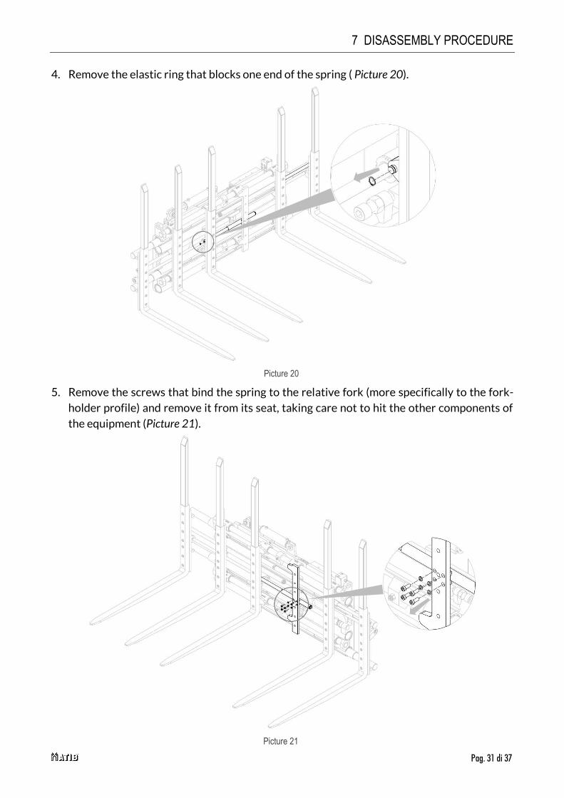
4. Remove the elastic ring that blocks one end of the spring ( Picture 20).
5. Remove the screws that bind the spring to the relative fork (more specifically to the fork-
holder profile) and remove it from its seat, taking care not to hit the other components of
the equipment (Picture 21).
Picture 20
Picture 21

7 DISASSEMBLY PROCEDURE
Pag. 32 di 37
7.4.1 Disassembly and reassembly of the gas spring
If it is necessary to replace the entire gas spring, reassemble everything following the
instructions listed in the previous point in reverse, if you also need to replace some component,
proceed as indicated below:
1. Clamp the saucer in a vice (being careful to not deform it).
2. Unscrew the cap, it is screwed inside the spring body.
3. Unscrew the pins screwed to the ends of the spring.
4. Separate the components from each other and replace the necessary parts.
5. Reassemble everything following the steps listed above in reverse.
6. Refer toPicture 22.
Picture 22
Cap
Housing
Spring
Pin

7 DISASSEMBLY PROCEDURE
Pag. 33 di 37
7.5 SLS cylinder removal from attachment
NOTE: The SLS cylinders are the same for all type of attachments, therefore the disassembly
procedure is the same.
1. Relieve the pressure of the hydraulic system.
2. Remove the two pins, with the relative elastic rings, which block the SLS cylinder.
3. Remove the cylinder.
4. Remove the stems and relative seal kit from their seat, one at a time.
5. Replace the worn parts, and reassemble everything, following the steps listed above in
reverse.
6. 7. If there is a damaged seal, it is advisable to replace the entire kit.
7. Refer to Picture 23.
Picture 23

7 DISASSEMBLY PROCEDURE
Pag. 34 di 37
7.5.1 Disassembly and reassembly SLS cylinder
If it is necessary to replace the entire SLS cylinder (use new one), reassemble everything
following the instructions listed in the previous point in reverse, if you also need to replace
some component, proceed as indicated below (Picture 24):
1. Place the cylinder on a horizontal plane.
2. Loosen the lock nut that locks the fork.
3. Unscrew the fork.
4. Unscrew the cylinder head.
5. Remove the cap.
6. The threads of ATIB cylinders are usually blocked with the aid of a thread locking solution.
If you find it difficult to unscrew the cap, it is necessary to slightly heat the area of the thread
concerned to facilitate unscrewing.
7. Separate the components from each other and replace the necessary parts.
8. If there is a damaged seal, it is advisable to replace the entire kit.
9. Reassemble everything, following the steps listed above in reverse.
Housing
Cap
Rod + Cylinder
Picture 24

8 BREAKDOWNS AND SOLUTIONS
Pag. 35 di 37
8 BREAKDOWNS AND SOLUTIONS
8.1 Breakdowns and solution
Should there be other problems, please contact A.T.I.B. S.r.l.
FAILURE CAUSE SOLUTION
Insufficient strength
Too low setting of the maximum pressure valve
Increase the pressure without exceeding the maximum limit
Insufficient pressure Contact the forklift manufacturer
Worn Pump Replace
worn cylinder seals Replace
Lack of oil in the tank Top up
Loss of pressure
leakage of oil from the pipes and joints Tighten the joints or replace them
leakage of oil from the cylinders Replace seal kits or, if it is necessary, the
cylinders
Loss load while sideshifting Lower the side shift pressure
Loss load Verify the blades cambering’s
Slow opening and closing
Low oil flow Check the tank level and the pump
Bottlenecks in the system: search and delete them
Insufficient pressure Set the maximum pressure valve
Mechanical deformations of some parts Repair or replace
Worn cylinder seals Replace
Lack of oil in the tank Top up
Irregular side shift
Presence of air in the hydraulic system Bleed the hydraulic system
Sliding parts usurated Replace
Excessive friction between the sliding parts
Clean and lubricate the sliding parts
Worn cylinder seals Replace
Lack of oil in the tank Top up Tab. 5

8 BREAKDOWNS AND SOLUTIONS
Pag. 36 di 37
8.2 Lubrication
1. Lubricate the sliding parts using the special grease nipples.
2. Lubricate the slide and relative scroll bar using the special grease nipples.
3. Lubricate the double hook using the special grease nipples (only for version with SLS).
Picture 25
Picture 26

atib.com I-D02-01-29 - Rev.2
A.T.I.B. S.r.l.
Via Quinzanese snc
25050 Dello (BS)
ITALIA
Tel: +39 030 9771711
follow us