Embed Size (px)
Citation preview

Installation and serviceinstructionsfor contractors
VIESMANN
Vitodens 200-WType B2HA, 125 and 150 kWWall mounted gas condensing boilerNatural gas and LPG version
For applicability, see the last page
VITODENS 200-W
5623 520 GB 6/2012 Please keep safe.

2
Please follow these safety instructions closely to prevent accidents and mate-rial losses.
Safety instructions explained
DangerThis symbol warns against therisk of injury.
! Please noteThis symbol warns against therisk of material losses and envi-ronmental pollution.
NoteDetails identified by the word "Note" con-tain additional information.
Target group
These instructions are exclusivelydesigned for qualified personnel.■ Work on gas equipment must only be
carried out by a qualified gas fitter.■ Work on electrical equipment must
only be carried out by a qualified elec-trician.
■ The system must be commissioned bythe system installer or a qualified per-son authorised by the installer.
Regulations
Observe the following when working onthis system■ all legal instructions regarding the pre-
vention of accidents,■ all legal instructions regarding envi-
ronmental protection,■ the Code of Practice of relevant trade
associations,
■ all current safety regulations asdefined by DIN, EN, DVGW, TRGI,TRF, VDE and all locally applicablestandards,
■ Gas Safety (Installation & Use) Regu-lations– the appropriate Building Regulation
either the Building regulations, theBuilding Regulation (Scotland),Building Regulations (Northern Ire-land),
– the Water Fittings Regulation orWater Bylaws in Scotland,
– the current I.E.E. Wiring Regula-tions.
If you smell gas
DangerEscaping gas can lead to explo-sions which may result in seriousinjury.■ Never smoke. Prevent naked
flames and sparks. Neverswitch lights or electrical appli-ances ON or OFF.
■ Close the gas shut-off valve.■ Open windows and doors.■ Remove all people from the
danger zone.■ Notify your gas or electricity
supplier from outside the build-ing.
■ Shut off the electricity supply tothe building from a safe place(outside the building).
Safety instructions
Safety instructions
5623
520
GB

3
If you smell flue gas
DangerFlue gas can lead to life-threat-ening poisoning.■ Shut down the heating system.■ Ventilate the boiler room.■ Close all doors leading to the
living space.
Working on the system
■ When using gas as fuel, also close themain gas shut-off valve and safeguardagainst unauthorised reopening.
■ Isolate the system from the power sup-ply and check that it is no longer 'live',e.g. by removing a separate fuse or bymeans of a main isolator.
■ Safeguard the system against unau-thorised reconnection.
! Please noteElectronic modules can be dam-aged by electro-static dis-charges.Touch earthed objects, such asheating or water pipes, to dis-charge static loads.
Repair work
! Please noteRepairing components which ful-fil a safety function can compro-mise the safe operation of yourheating system.Replace faulty components onlywith original Viessmann spareparts.
Ancillary components, spare andwearing parts
! Please noteSpare and wearing parts whichhave not been tested togetherwith the heating system can com-promise its function. Installingnon-authorised components andnon-approved modifications/con-version can compromise safetyand may invalidate our warranty.For replacements, use only orig-inal spare parts from Viessmannor those which are approved byViessmann.
Safety instructions
Safety instructions (cont.)
5623
520
GB

4
Installation instructionsPreparing for installationProduct information.............................................................................................. 6Preparing for installation....................................................................................... 7
Installation sequenceFitting the boiler and making connections............................................................ 9Heating water side connection............................................................................. 13Flue gas connection............................................................................................. 13Condensate connection........................................................................................ 14Gas connection.................................................................................................... 15Opening the control unit casing............................................................................ 15Electrical connections........................................................................................... 17Closing the control unit casing and inserting the programming unit..................... 27
Service instructionsCommissioning, inspection, maintenanceSteps - commissioning, inspection and maintenance.......................................... 28Further details regarding the individual steps....................................................... 30
Code 1Calling up coding level 1...................................................................................... 66General/group "1"................................................................................................. 67Boiler/group "2".................................................................................................... 70DHW/group "3"..................................................................................................... 70Solar/group "4"..................................................................................................... 71Heating circuit 1, heating circuit 2, heating circuit 3/group "5"............................. 73
Code 2Calling up coding level 2...................................................................................... 80General/group "1"................................................................................................. 81Boiler/group "2".................................................................................................... 90DHW/group "3"..................................................................................................... 92Solar/group "4"..................................................................................................... 94Heating circuit 1, heating circuit 2, heating circuit 3/group "5"............................. 98
Diagnosis and service scansCalling up the service level................................................................................... 107Diagnosis.............................................................................................................. 108Checking outputs (relay test)................................................................................ 114
Index
Index
5623
520
GB
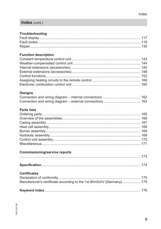
5
TroubleshootingFault display......................................................................................................... 117Fault codes........................................................................................................... 119Repair................................................................................................................... 135
Function descriptionConstant temperature control unit........................................................................ 143Weather-compensated control unit...................................................................... 144Internal extensions (accessories)......................................................................... 145External extensions (accessories)........................................................................ 148Control functions.................................................................................................. 152Assigning heating circuits to the remote control................................................... 160Electronic combustion control unit........................................................................ 160
DesignsConnection and wiring diagram – internal connections ....................................... 162Connection and wiring diagram – external connections....................................... 163
Parts listsOrdering parts...................................................................................................... 165Overview of the assemblies................................................................................. 166Casing assembly.................................................................................................. 167Heat cell assembly............................................................................................... 168Burner assembly.................................................................................................. 169Hydraulic assembly.............................................................................................. 169Control unit assembly........................................................................................... 170Miscellaneous....................................................................................................... 171
Commissioning/service reports............................................................................................................................. 173
Specification....................................................................................................... 174
CertificatesDeclaration of conformity...................................................................................... 175Manufacturer's certificate according to the 1st BImSchV [Germany]................... 175
Keyword index.................................................................................................... 176
Index
Index (cont.)
5623
520
GB

6
Vitodens 200-W, B2HA
Preset for operation with natural gas E and LL.For conversion to LPG P (without conversion kit), see page 37.
Conversion for other countriesThe Vitodens 200-W should generally only be delivered to those countries specifiedon the type plate. For deliveries to alternative countries, an approved contractor, onhis own initiative, must arrange individual approval in accordance with the law of theland.
Multi boiler systemIn connection with the installation of a multi boiler system observe the installationinstructions of the multi boiler system accessories.
Preparing for installation
Product information
5623
520
GB

7
Dimensions and connections
! Please noteTo prevent equipment damage,
install all pipework free of loadand torque stresses.
165.5165.5
923
1440
95
689
278
905
600
P
40
200
855
1975
1950
E
LM
O
K
H
N
A
B
C
GD F
70 70195
A Safety valveB Expansion vessel connection G1C Boiler flow 7 54 mm
D Cylinder flow 7 42 mmE Gas connection R 1F Cylinder return 7 42 mm
Preparing for installation
Preparing for installation56
23 5
20 G
B
Inst
alla
tion

8
G Boiler return 7 54 mmH Connection sets (accessories,
shown without the thermal insula-tion supplied)
K Cable entry area at the backL Without connection set (accesso-
ries)M With connection set (accessories)
N Recommended dimension (singleboiler system without mountingframe)
O Recommended dimension (multiboiler system and single boiler sys-tem with mounting frame)
P Condensate drain
Preparing for the boiler installation
NoteThis boiler (protection IP X4 D) isapproved for installation in wet roomsinside safety zone 1 according toDIN VDE 0100 [Germany], if hosedwater can be prevented.Observe DIN VDE 0100 [or local regula-tions].
1. Prepare the water connections. Thor-oughly flush the heating system.
2. Prepare gas connection to TRGI [orlocal regulations].
3. Prepare the electrical connections.■ Power cable: NYM-J 3 x 1.5 mm2,
max. fuse 16 A, 230 V~.■ Accessory cables: NYM with the
required number of conductors forthe external connections.
■ Allow all cables in area "K" to pro-trude 1400 mm from the wall.
Preparing for installation
Preparing for installation (cont.)
5623
520
GB

9
Removing boiler from packaging and levelling
2x
3.
1.
2..
4.
1. Remove packing cushions and keepthem safe.They are used as a support duringlevelling.
2. Undo two screws on the underside.
3. Remove front panel.
4. Push packing cushions onto theunderside of the boiler.
Installation sequence
Fitting the boiler and making connections56
23 5
20 G
B
Inst
alla
tion

10
A
5.
A 7 9 mm drilled holes for attachinglifting gear
5. ! Please noteTo prevent damage,do not level boiler withoutpacking cushions.
Level boiler with pallet.
Installation sequence
Fitting the boiler and making connections (cont.)
5623
520
GB

11
Fitting the wall mounting bracket
NoteThe enclosed screws and rawl plugs areonly suitable for concrete. For other con-struction materials, use fixings that aresuitable for 145 kg loads.
1975
Ø 12
B C
D
A
2.
1.
A Reference point: boiler top edgeB Installation template (included with
the boiler)
C Top edge finished floorD Recommendation
Installation sequence
Fitting the boiler and making connections (cont.)
5623
520
GB
Inst
alla
tion

12
Hooking the boiler into the wall mounting bracket and levellingit
1.
3.
2x
3.
2.
Installation sequence
Fitting the boiler and making connections (cont.)
5623
520
GB

13
A
B C D E
A Expansion vessel connectionB Boiler flow C Cylinder flow
D Cylinder return E Boiler return
NoteResidual water may escape when undo-ing the locking caps.
Flue gas connection
NoteThe labels "System certificate" and "Sko-berne GmbH flue system" enclosed withthe technical documentation may only beused in conjunction with the Viessmannflue system made by Skoberne.
Installation sequence
Heating water side connection56
23 5
20 G
B
Inst
alla
tion

14
A1. Only for open flue operation:
Remove outer gasket A (ventilationair).
2. Connect flue pipe or flue ventilationair pipe.
Flue system installation instruc-tions.
Condensate connection
Connect the condensate hose with aconstant fall and a pipe vent to the publicsewage system or to a neutralising sys-tem.
Installation sequence
Flue gas connection (cont.)
5623
520
GB

15
A
Information on operation with LPGWe recommend the installation of anexternal safety solenoid valve wheninstalling the boiler in rooms belowground level.
1. Seal in gas shut-off valve A into thegas supply pipe.
2. Carry out a tightness test.
NoteOnly use suitable and approved leakdetecting agents (EN 14291) anddevices for the tightness test. Leakdetection agents with unsuitable con-stituents (e.g. nitrites, sulphides) cancause material damage.Remove residues of the leak detec-tion agent after testing.
! Please noteExcessive test pressure maydamage the boiler and the gasvalve. Max. test pressure 150 mbar.Where higher pressure isrequired for tightness tests,disconnect the boiler and thegas valves from the gas sup-ply pipe (undo the fitting).
3. Vent the gas line.
Conversion to other gas types: Service instructions
Opening the control unit casing
! Please noteElectronic assemblies can bedamaged by electrostatic dis-charge.Before beginning work, touchearthed objects, such as heatingor water pipes, to discharge staticloads.
Installation sequence
Gas connection56
23 5
20 G
B
Inst
alla
tion

16
3. 2. 2x
1.
4.4x
5.
Installation sequence
Opening the control unit casing (cont.)
5623
520
GB
17
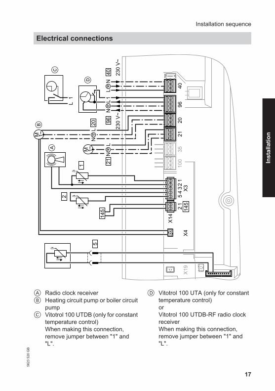
LN
230
V~23
0 V~
5
9640
4096
2035
100
1LN
X42
1
2
1
321
54 X3
LN
21
M 1~
X19
X14
A
B
21
20
L1
C
D
145 14
5
LN
M 1~
A Radio clock receiverB Heating circuit pump or boiler circuit
pumpC Vitotrol 100 UTDB (only for constant
temperature control)When making this connection,remove jumper between "1" and"L".
D Vitotrol 100 UTA (only for constanttemperature control)orVitotrol 100 UTDB-RF radio clockreceiverWhen making this connection,remove jumper between "1" and"L".
Installation sequence
Electrical connections56
23 5
20 G
B
Inst
alla
tion

18
Connections at plug 230 V~sÖ Boiler circuit pump or heating circuit
pump, variable speed with 0 - 10 Vconnection
sA Circulation pump, optional connec-tion:■ DHW circulation pump■ External heating circuit pump■ Circulation pump for cylinder
heatingfÖ Power supplylH ■ Power supply for accessories
■ External demand/blocking■ Vitotrol 100 UTA■ Vitotrol 100 UTDB■ Vitotrol 100 UTDB-RF
Connections at LV plug! Outside temperature sensor? Flow temperature sensor for low
loss header (accessories)
% Cylinder temperature sensor (partof the DHW cylinder connectionset)
aVG KM BUS subscriber (accessory)■ Vitotrol 200A or 300A remote
control■ Vitocom 100■ Extension kit for one heating cir-
cuit with mixer■ Solar control module, type SM1■ Vitosolic■ Extension AM1■ Extension EA1■ Wireless base station
Information on connectingaccessoriesWhen connecting accessoriesobserve the separate installationinstructions provided with them.
Circulation pump at plug sÖ:
A 1~M
sÖL N? x4
B
A Circulation pumpB Only with variable speed heating cir-
cuit pump:Plug in 0 - 10 V connection at X4.
Rated current 2(1) A~Rated voltage 230 V~
Installation sequence
Electrical connections (cont.)
5623
520
GB

19
Circulation pump at plug sA:
A1~M
sAL N?
A Circulation pump
Rated current 2(1) A~Rated voltage 230 V~
Set function of connected componentin coding address "39"Function CodeDHW circulation pump 39:0Heating circuit pump forheating circuit without mixerA1
39:1
Circulation pump for cylinderheating (delivered condi-tion)
39:2
External demand via switching contact
Connection options:■ Extension EA1 (accessory, see sepa-
rate installation instructions).■ Plug lH.
Connection
! Please note'Live' contacts lead to short cir-cuits or phase failure.The external connection must befloating.
Installation sequence
Electrical connections (cont.)
5623
520
GB
Inst
alla
tion

20
Plug lH Extension EA1
A
lHN?1 L
A Floating contactWhen making this connec-tion, remove jumper be-tween 1 and L.
B[{SDE [{DDE[{ADE
A
A Floating contactB Extension EA1
Burner operation is load-dependent if the contact is closed. The boiler water is heat-ed to the value set in coding address "9b" in group "General"/"1". The boiler watertemperature is limited by this set value and the electronic maximum limit (codingaddress "06" in group "Boiler"/"2").
Codes
Plug lH Extension EA1"4b:1" in group "General"/"1" Set "3A" (DE1), "3b" (DE2) or "3C" (DE3) in
group "General"/"1" to 2.■ Select effect of the function on the relevant heating circuit pump in coding address
"d7" in group "Heating circuit"/"5".■ Select effect of the function on the circulation pump for cylinder heating in coding
address "5F" in group "DHW"/"3".
External demand via 0 – 10 V input
Connection at 0 – 10 V input to exten-sion EA1.Ensure DC separation between the earthconductor and the negative pole of theon-site voltage source.
Installation sequence
Electrical connections (cont.)
5623
520
GB

21
L?N L?N
fÖ
S P
aBJ
230 V~
Ö
[{{]0-10V f-]A
= 0-10 V
+
1 2
0 – 1 V ≙ no default set boiler watertemperature
1 V ≙ Set value 10 °C10 V ≙ Set value 100 °C
External blocking via switching contact
Connection options:■ Plug lH.■ Extension EA1 (accessory, see sepa-
rate installation instructions).
! Please note'Live' contacts lead to short cir-cuits or phase failure.The external connection must befloating.
Installation sequence
Electrical connections (cont.)
5623
520
GB
Inst
alla
tion

22
Plug lH Extension EA1
A
lHN?1 L
A Floating contactWhen making this connection, re-move jumper between 1 and L.
B[{SDE [{DDE[{ADE
A
A Floating contactB Extension EA1
The burner is switched off if this contact is closed. The heating circuit pump andcirculation pump for cylinder heating are switched according to the set code (see thefollowing table "Codes").
! Please noteWhen blocked, there is no frostprotection for the heating system.
Codes
Plug lH Extension EA1"4b:2" in group "General"/"1" Set "3A" (DE1), "3b" (DE2) or "3C" (DE3) in
group "General"/"1" to 3 or 4.■ Select effect of the function on the heating circuit pump in coding address "d6" in
group "Heating circuit"/"5".■ Select effect of the function on the circulation pump for cylinder heating in coding
address "5E" in group "DHW"/"3".
Outside temperature sensor !
Fitting outside temperature sensor RF(wireless accessory):
Wireless base station
Installation sequence
Electrical connections (cont.)
5623
520
GB

23
Fitting location for outside tempera-ture sensor
■ North or north-westerly wall, 2 to2.5 m above ground level; in multistorey buildings, in the top half of thesecond floor
■ Not above windows, doors or vents
■ Not immediately below balconies orgutters
■ Never render over
Outside temperature sensor connec-tion
2-core lead, length up to 35 m with across-section of 1.5 mm2
Power supply for accessories at plug lH
230 V~Where the boiler is installed in a wetarea, the connection of accessories tothe power supply must not be carried outat the control unit. The power supplyconnection for accessories can be madeimmediately at the control unit, if theboiler is installed outside wet areas. Thisconnection is switched directly with theON/OFF switch of the control unit.
If the total system current exceeds 6 A,connect one or more extensions via anON/OFF switch directly to the mains sup-ply (see next chapter).
Installation sequence
Electrical connections (cont.)
5623
520
GB
Inst
alla
tion

24
Connection of accessories
Power supply of all accessories via the boiler control unit
145
145
40 A
40 145
145
40 A
40
B C
145
40 96
A
145
145
40 A
40
D
E
Some accessories with direct power supply
145
145
40 A
40 145
145
40 A
40
B C
145
40 96
A14
514
5
40 A
40
D
E
A Boiler control unitB Extension kit for heating circuit with
mixer M2C Extension kit for heating circuit with
mixer M3
D Extension AM1, EA1 and/or solarcontrol module, type SM1
E ON/OFF switch
If the current flowing to the connectedworking parts (e.g. circulation pumps) ishigher than the safety level of the acces-sory, the output concerned should onlybe used to control an on-site relay.
Accessories Internal fuseprotection
Extension kit for heat-ing circuit with mixer
2 A
Extension AM1 4 AExtension EA1 2 ASolar control module,type SM1
2 A
Installation sequence
Electrical connections (cont.)
5623
520
GB

25
Power supply fÖ
DangerIncorrect core allocation canresult in serious injury and dam-age to the appliance.Take care not to interchangewires "L1" and "N".
■ Install an isolator in the power cablewhich simultaneously separates allnon-earthed conductors from themains with contact separation of atleast 3 mm.Furthermore, we recommend instal-ling an AC/DC-sensitive RCD (RCDclass B ) for DC (fault) currentsthat can occur with energy efficientequipment.
■ Max. fuse rating 16 A.
Installation sequence
Electrical connections (cont.)
5623
520
GB
Inst
alla
tion

26
Routing the connecting cables
! Please noteIf connecting cables touch hot components they will be damaged. When routing and securing connecting cables on site, ensure that the maxi-mum permissible temperatures for these cables are not exceeded.
5
A Low voltage connectionsB 230 V connectionsC Internal extensionD Main PCBE Communication module
F Cable grommet for power cable% Plugs for connecting the cylinder
temperature sensor to the cable har-ness
Remove the existing cable grommetwhen using larger cross-sections (up to7 14 mm). Secure the cable with thecable grommet plugged into the lowercasing section F (black).
Installation sequence
Electrical connections (cont.)
5623
520
GB

27
1.
3. 2x2.
4.
4.
6.
Insert programming unit (packed sepa-rately) into the control unit support.
NoteThe programming unit can also behoused in a wall mounting base (acces-sory) near the boiler.
Wall mounting base installationinstructions
Installation sequence
Closing the control unit casing and inserting the programming unit
5623
520
GB
Inst
alla
tion
28
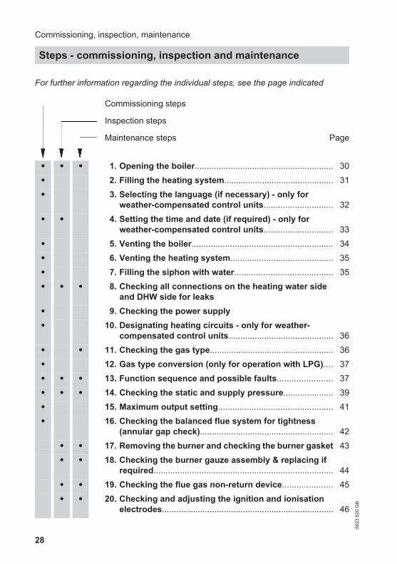
For further information regarding the individual steps, see the page indicated
Commissioning steps
Inspection steps
Maintenance steps Page
• • • 1. Opening the boiler.......................................................... 30
• 2. Filling the heating system.............................................. 31
• 3. Selecting the language (if necessary) - only forweather-compensated control units............................. 32
• • 4. Setting the time and date (if required) - only forweather-compensated control units............................. 33
• 5. Venting the boiler........................................................... 34
• 6. Venting the heating system........................................... 35
• 7. Filling the siphon with water......................................... 35
• • • 8. Checking all connections on the heating water sideand DHW side for leaks
• 9. Checking the power supply
• 10. Designating heating circuits - only for weather-compensated control units............................................ 36
• • 11. Checking the gas type.................................................... 36
• 12. Gas type conversion (only for operation with LPG).... 37
• • • 13. Function sequence and possible faults....................... 37
• • • 14. Checking the static and supply pressure..................... 39
• 15. Maximum output setting................................................ 41
• 16. Checking the balanced flue system for tightness(annular gap check)........................................................ 42
• • 17. Removing the burner and checking the burner gasket 43
• • 18. Checking the burner gauze assembly & replacing ifrequired........................................................................... 44
• • 19. Checking the flue gas non-return device..................... 45
• • 20. Checking and adjusting the ignition and ionisationelectrodes........................................................................ 46
Commissioning, inspection, maintenance
Steps - commissioning, inspection and maintenance
5623
520
GB

29
Commissioning steps
Inspection steps
Maintenance steps Page
• • 21. Cleaning the combustion chamber/heat exchangerand installing the burner................................................ 47
• • 22. Checking the condensate drain and cleaning thesiphon.............................................................................. 48
• • 23. Checking the neutralising system (if installed)
• • 24. Checking the diaphragm expansion vessel andsystem pressure............................................................. 48
• • • 25. Checking the function of safety valves
• • • 26. Checking firm seating of electrical connections
• • • 27. Checking all gas equipment for tightness at operatingpressure .......................................................................... 49
• • • 28. Checking combustion quality........................................ 49
• • • 29. Checking the flue system for unrestricted flow andtightness
• • • 30. Checking the external LPG safety valve (if installed)
• 31. Matching the control unit to the heating system ........ 51
• 32. Adjusting the heating curves (only for weather-compensated control units)........................................... 58
• 33. Connecting the control unit to the LON....................... 61
• 34. Calling up and resetting the "Service" display............ 62
• • • 35. Fitting the front panel..................................................... 64
• 36. Instructing the system user........................................... 65
Commissioning, inspection, maintenance
Steps - commissioning, inspection and… (cont.)
5623
520
GB
Serv
ice

30
Opening the boiler
2x
2.
1.
4.
3.
Commissioning, inspection, maintenance
Further details regarding the individual steps
5623
520
GB
31
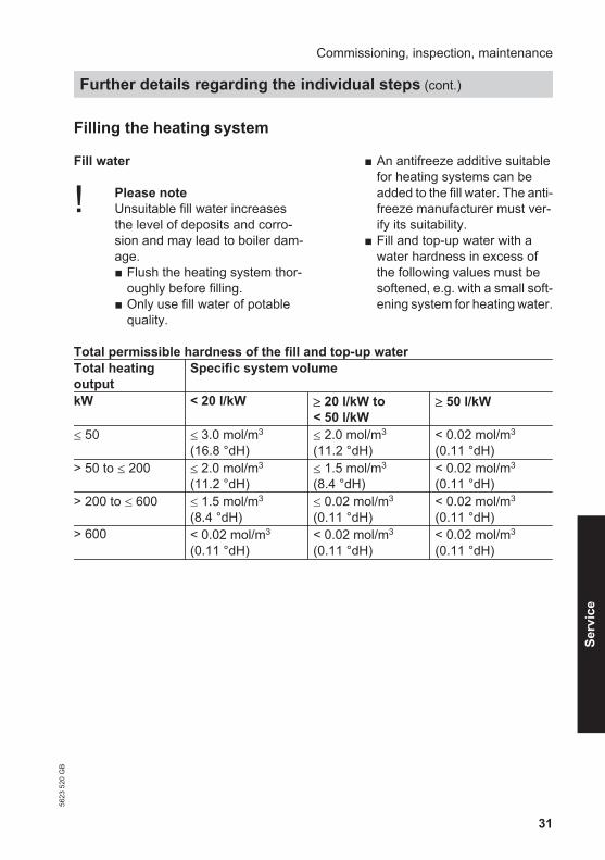
Filling the heating system
Fill water
! Please noteUnsuitable fill water increasesthe level of deposits and corro-sion and may lead to boiler dam-age.■ Flush the heating system thor-
oughly before filling.■ Only use fill water of potable
quality.
■ An antifreeze additive suitablefor heating systems can beadded to the fill water. The anti-freeze manufacturer must ver-ify its suitability.
■ Fill and top-up water with awater hardness in excess ofthe following values must besoftened, e.g. with a small soft-ening system for heating water.
Total permissible hardness of the fill and top-up waterTotal heatingoutput
Specific system volume
kW < 20 l/kW ≥ 20 l/kW to< 50 l/kW
≥ 50 l/kW
≤ 50 ≤ 3.0 mol/m3
(16.8 °dH)≤ 2.0 mol/m3
(11.2 °dH)< 0.02 mol/m3
(0.11 °dH)> 50 to ≤ 200 ≤ 2.0 mol/m3
(11.2 °dH)≤ 1.5 mol/m3
(8.4 °dH)< 0.02 mol/m3
(0.11 °dH)> 200 to ≤ 600 ≤ 1.5 mol/m3
(8.4 °dH)≤ 0.02 mol/m3
(0.11 °dH)< 0.02 mol/m3
(0.11 °dH)> 600 < 0.02 mol/m3
(0.11 °dH)< 0.02 mol/m3
(0.11 °dH)< 0.02 mol/m3
(0.11 °dH)
Commissioning, inspection, maintenance
Further details regarding the individual steps (cont.)
5623
520
GB
Serv
ice

32
A
1. Check the pre-charge pressure of thediaphragm expansion vessel.
2. Close the gas shut-off valve.
3. Connect the supply hose to boilerdrain & fill valve A.
4. Fill the heating system via boiler drain& fill valve A. (minimum systempressure > 1.0 bar).Permiss. operating pressure: 6 bar.
5. Close boiler drain & fill valve A.
Selecting the language (if necessary) - only for weather-com-pensated control units
At the commissioning stage, the displayis in German (factory setting).
Extended menu:
1. å
2. "Settings"
3. "Language"
Sprache
Cesky CZDeutsch DE
DanskEnglish
DKGB
Wählen mit Ø
ç
4. Set the required language with / .
Commissioning, inspection, maintenance
Further details regarding the individual steps (cont.)
5623
520
GB

33
Setting the time and date (if required) - only for weather-com-pensated control units
During commissioning, or after pro-longed time out of use, the time and dateneed to be reset.
Extended menu:
1. å
2. "Settings"
3. "Time / Date"
4. Set current time and date.
NoteWhen time and date have been set, thecontrol unit automatically checks thefunction of the flue gas temperature sen-sor. The display shows: "Test flue gastemp sensor" and "Active".For further details regarding the flue gastemperature sensor test, seepage 139.
Commissioning, inspection, maintenance
Further details regarding the individual steps (cont.)
5623
520
GB
Serv
ice

34
Venting the boiler
B
A
1. Close the shut-off valves on the heat-ing water side.
2. Connect the supply hose to boilerdrain & fill valve A.
3. Plug the drain hose onto top tap Band connect to a drain.
4. Open taps A and B and vent atmains pressure (purge) until nosound of escaping air can be heardand no more air bubbles are visible.
5. Close taps A and B, open the shut-off valves on the heating water side.
6. Remove hoses again.
Commissioning, inspection, maintenance
Further details regarding the individual steps (cont.)
5623
520
GB

35
Venting the heating system
1. Close the gas shut-off valve andswitch the control unit ON.
2. Activate venting program (see nextsteps).
NoteFor function and sequence of theventing program, see page 154.
3. Check the system pressure.
Activating the venting function
Weather-compensated control unit Constant temperature control unitService menu1. Press OK and å simultaneously for
approx. 4 s.2. "Service functions"3. "Venting"
Venting function is enabled.4. Ending venting function:
Press OK or ä.
Service menu1. Press OK and å simultaneously for
approx. 4 s.2. Select "5" with Ú and confirm with
OK."ON" flashes.
3. Activate the venting function with OK."EL on" is shown constantly.
4. Ending venting function:Press ä.
Filling the siphon with water
E
F
C
D
A
B
1. Pull off cap A downwards.
2. Undo hose B.
3. Undo union nut C and pull off siphonD downwards.
4. Fill siphon D with water and refit it.
5. Refit hose B.
6. Push on cap A from below.
Commissioning, inspection, maintenance
Further details regarding the individual steps (cont.)
5623
520
GB
Serv
ice
36
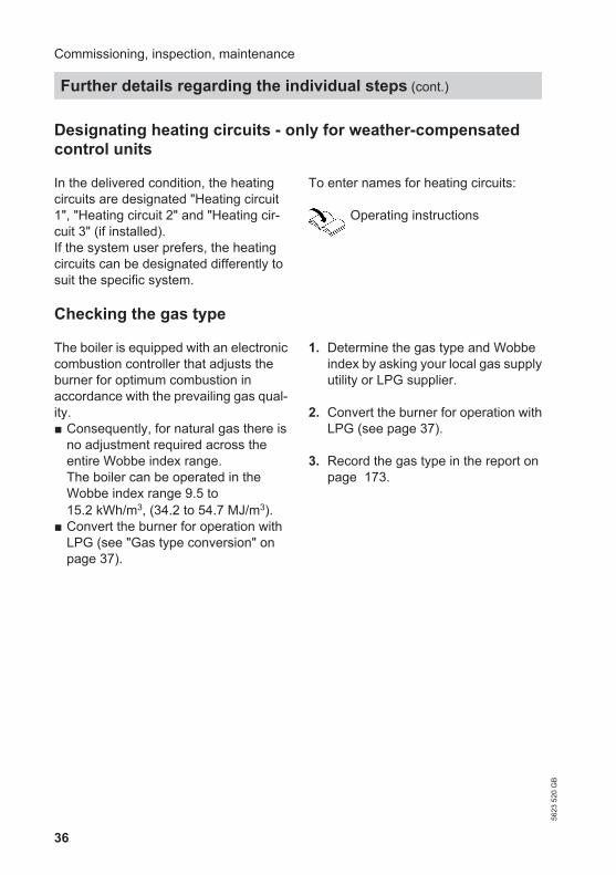
Designating heating circuits - only for weather-compensatedcontrol units
In the delivered condition, the heatingcircuits are designated "Heating circuit1", "Heating circuit 2" and "Heating cir-cuit 3" (if installed).If the system user prefers, the heatingcircuits can be designated differently tosuit the specific system.
To enter names for heating circuits:
Operating instructions
Checking the gas type
The boiler is equipped with an electroniccombustion controller that adjusts theburner for optimum combustion inaccordance with the prevailing gas qual-ity.■ Consequently, for natural gas there is
no adjustment required across theentire Wobbe index range.The boiler can be operated in theWobbe index range 9.5 to15.2 kWh/m3, (34.2 to 54.7 MJ/m3).
■ Convert the burner for operation withLPG (see "Gas type conversion" onpage 37).
1. Determine the gas type and Wobbeindex by asking your local gas supplyutility or LPG supplier.
2. Convert the burner for operation withLPG (see page 37).
3. Record the gas type in the report onpage 173.
Commissioning, inspection, maintenance
Further details regarding the individual steps (cont.)
5623
520
GB

37
Gas type conversion (only for operation with LPG)
1
2
A
1. Set adjusting screw A on the gastrain to "2".
2. Switch ON/OFF switch "8" on.
3. Select the gas type in coding address"82":■ Call up code 2■ Call up "General" (weather-com-
pensated control unit)orGroup "1" (constant temperaturecontrol unit)
■ In coding address "11", selectvalue "9"
■ In coding address "82", selectvalue "1" (LPG operation)
■ In code "11", select value ≠ "9".■ End service functions.
4. Open the gas shut-off valve.
5. Affix label "G 31" (included with thetechnical documentation) in a clearlyvisible position, near the gas train onthe cover panel.
Function sequence and possible faults
Display Measures Control unit is-
sues a heat de-mand
no Increase set valueand ensure heat isdrawn off
yes
Fan starts no After approx. 51 sfault F9
Check the fan, fanconnecting cables,power at the fanand fan control
Commissioning, inspection, maintenance
Further details regarding the individual steps (cont.)
5623
520
GB
Serv
ice

38
yes
Ignition no Fault EE Check the ignitionmodule (controlvoltage 230 Vacross plugs"X2.1" and "X2.2")
yes
Gas train opens no Fault EE Check the gas train(control voltage230 V); check thegas supply pres-sure
yes
Ionisation currentbuilds Symbol A
no Fault EE Check the ionisa-tion electrode ad-justment and thegas line for air-locks
yes
Burner in opera-tion
no Stops below theset boiler watertemperature andrestarts immedi-ately
Check the flue gassystem for tight-ness (flue gas re-circulation), checkthe gas flow pres-sure
Commissioning, inspection, maintenance
Further details regarding the individual steps (cont.)
5623
520
GB

39
yes
Automatic calibra-tion of the com-bustion controller
no
Fault E3 Ensure adequateheat transfer.Press reset buttonR.
Fault Eb Check gap be-tween ionisationelectrode andburner gauze as-sembly.Check allocation ofgas type (codingaddress 82, gastrain setting).Check flue sys-tem; remedy fluegas recirculation ifrequired.Press reset buttonR.
For further details regarding faults, seepage 117.
Checking the static and supply pressure
DangerCO build-up as a result of incor-rect burner adjustment can haveserious health implications.Carry out a CO test before andafter work on gas appliances.
Operation with LPGFlush the LPG tank twice during com-missioning or replacement. Vent the tankand gas supply line thoroughly afterflushing.
Commissioning, inspection, maintenance
Further details regarding the individual steps (cont.)
5623
520
GB
Serv
ice

40
A
1. Close the gas shut-off valve.
2. Undo screw A inside test nipple"PE" on the gas train, but do notremove it, and connect the pressuregauge.
3. Open the gas shut-off valve.
4. Check the static pressure and recordthe value in the report on page 173.
Set value: max. 57.5 mbar.
5. Start the boiler.
NoteDuring commissioning, the boiler canenter a fault state because of airlocksin the gas line. After approx. 5 s,press R to reset the burner.
6. Check the supply (flow) pressure. Setvalues:■ Natural gas 20 mbar■ LPG 50 mbar
NoteUse a suitable measuring device witha resolution of at least 0.1 mbar tomeasure the supply pressure.
7. Record the actual value in the servicereport.Take the action shown in the follow-ing table.
8. Shut down the boiler, close the gasshut-off valve, remove the pressuregauge and close test nipple A withthe screw.
Commissioning, inspection, maintenance
Further details regarding the individual steps (cont.)
5623
520
GB

41
9. DangerGas escaping from the testnipple leads to a risk of explo-sion.Check for gas tightness.
Open the gas shut-off valve, start theboiler and check for tightness at testnipple A.
Supply (flow) pres-sure for naturalgas
Supply (flow)pressure for LPG
Action
below 15 mbar below 42.5 mbar Do not start the boiler. Notify your gassupply utility or LPG supplier.
15 to 25 mbar 42.5 to 57.5 mbar Start the boiler.above 25 mbar above 57.5 mbar Install a separate gas pressure governor
upstream of the system and regulate thepre-charge pressure to 20 mbar for natu-ral gas or 50 mbar for LPG. Notify yourgas supply utility or LPG supplier.
Maximum output setting
The maximum output for heating oper-ation can be limited. The limit is set viathe modulation range. The max. adjust-able output is limited upwards by theboiler coding card.
Weather-compensated control unit:
1. Press OK and å simultaneouslyfor approx. 4 s.
2. "Service functions"
3. "Max. output"
4. "Change?" Select "Yes".A value appears on the display (e.g."85"). In the delivered condition, thisvalue represents 100 % of rated heat-ing output.
5. Set the required value.
Constant temperature control unit:
1. Press OK and å simultaneouslyfor approx. 4 s.
Commissioning, inspection, maintenance
Further details regarding the individual steps (cont.)
5623
520
GB
Serv
ice

42
2. Select "3" with Ú and confirm withOK.A value flashes on the display (e.g."85") and "A" appears. In the deliv-ered condition, this value represents100 % of rated heating output.
3. Select required value and confirmwith OK.
Checking the balanced flue system for tightness (annular gapcheck)
A
A Combustion air aperture
For balanced flue systems testedtogether with the wall mounted gas firedboiler, the requirement for a tightnesstest during commissioning by the fluegas inspector is not applicable.
We recommend that your heating engi-neer carries out a simple leak/tightnesstest during the commissioning of yoursystem. For this, it would be sufficient tocheck the CO2 or O2 concentration in thecombustion air at the annular gap of thebalanced flue pipe.The flue pipe is deemed to be gas-tightif the CO2 concentration in the combus-tion air is no higher than 0.2 % or theO2 concentration is at least 20.6 %.If actual CO2 values are higher or O2 val-ues are lower, then pressure test the fluepipe with a static pressure of 200 Pa.
Commissioning, inspection, maintenance
Further details regarding the individual steps (cont.)
5623
520
GB

43
Removing the burner and checking the burner gasket
A
B
C
D
E
F
G
H
K
1. Switch OFF the main power supplyand the ON/OFF switch at the controlunit.
2. Close the gas shut-off valve and safe-guard against reopening.
3. Unlock control unit A and pivot for-wards.
4. Remove cover panel B.
5. Pull cables from fan motor C, gastrain D, ignition unit E and ionisa-tion electrode F.
6. Undo gas supply pipe fitting G.
7. Undo six screws H and remove theburner.
! Please noteTo prevent damage,never touch the mesh of theburner gauze assembly.
Commissioning, inspection, maintenance
Further details regarding the individual steps (cont.)
5623
520
GB
Serv
ice

44
8. Check burner gasket K for damage.Replace gasket if required.
Checking the burner gauze assembly & replacing if required
C B6xEF D4x
A
1. Remove electrodes A.
2. Undo six retaining clips B on ther-mal insulation ring C and thenremove thermal insulation ring C.
3. Undo four Torx screws D andremove burner gauze assembly Ewith burner gauze assembly gasketF.
Commissioning, inspection, maintenance
Further details regarding the individual steps (cont.)
5623
520
GB

45
4. Insert new burner gauze assemblyE with new gasket F and securewith four Torx screws.Torque: 4.0 Nm
5. Refit thermal insulation ring C andelectrodes A.
Checking the flue gas non-return device
B
A
1. Undo three screws and remove fanA.
2. Remove flue gas non-return deviceB.
Commissioning, inspection, maintenance
Further details regarding the individual steps (cont.)
5623
520
GB
Serv
ice

46
3. Check the damper and gasket for dirtand damage. Replace as neces-sary.
4. Refit flue gas non-return device B.
5. Refit fan A and secure with threescrews.Torque: 3.0 Nm.
Checking and adjusting the ignition and ionisation electrodes
14±16+20 4+0
,5 0
A A B
A Ignition electrodes B Ionisation electrode
1. Check the electrodes for wear andcontamination.
2. Clean the electrodes with a smallbrush (not with a wire brush) or sand-paper.
! Please noteDo not damage the mesh oftheburner gauze assembly.
3. Check the electrode gaps. If the gapsare not as specified or the electrodesare damaged, replace the electrodestogether with new gaskets and adjustthem as required. Tighten the elec-trode fixing screws with 3 Nm.
Commissioning, inspection, maintenance
Further details regarding the individual steps (cont.)
5623
520
GB

47
Cleaning the combustion chamber/heat exchanger and installingthe burner
A
1. ! Please noteScratches on parts that are incontact with flue gas can leadto corrosion.Never use brushes to cleanthe heating surface.
Use a vacuum cleaner to remove res-idues from heat exchanger A in thecombustion chamber.
2. If necessary, spray slightly acidic,chloride-free cleaning agents basedon phosphoric acid onto heatexchanger A and let the solutionsoak in for at least 20 min.
3. Thoroughly flush heat exchanger Awith water.
4. Install the burner and torque thescrews diagonally with 8.5 Nm.
5. Fit the gas supply pipe with a newgasket. Torque fittings with 15 Nm.
Commissioning, inspection, maintenance
Further details regarding the individual steps (cont.)
5623
520
GB
Serv
ice

48
6. Check the gas connections for tight-ness.
DangerEscaping gas leads to a risk ofexplosion.Check all fittings for gas tight-ness.
7. Connect the electrical cables/leads tothe corresponding components.
Checking the condensate drain and cleaning the siphon
NoteIf condensate escapes at vent apertureA or B, clean or (if necessary) replacethe following drain line.
E
F
C
D
A
B
1. Pull off cap C downwards.
2. Undo hose D.
3. Undo union nut E and pull siphonF downwards.
4. Clean siphon F.
5. Check that the condensate can drainfreely to the public sewage system.
6. Fill siphon F with water and reas-semble.
7. Refit hose D.
8. Push on cap C from below.
Checking the diaphragm expansion vessel and system pressure
NoteCarry out this test on a cold system.
1. Drain the system or close the capvalve on the diaphragm expansionvessel and reduce the pressure untilthe pressure gauge indicates "0".
Commissioning, inspection, maintenance
Further details regarding the individual steps (cont.)
5623
520
GB

49
2. If the pre-charge pressure of the dia-phragm expansion vessel is lowerthan the static system pressure, topup with nitrogen until the pre-chargepressure is raised by 0.1 to 0.2 bar.
3. Top up with water until the chargepressure of the cooled system is 0.1to 0.2 bar higher than the pre-chargepressure of the diaphragm expansionvessel. Permiss. operating pressure: 6 bar.
Checking all gas equipment for tightness at operating pressure
DangerEscaping gas leads to a risk ofexplosion.Check gas equipment for tight-ness.
NoteOnly use suitable and approved leakdetecting agents (EN 14291) and devi-ces for the tightness test. Leak detectionagents with unsuitable constituents (e.g.nitrites, sulphides) can cause materialdamage.Remove residues of the leak detectionagent after testing.
Checking combustion quality
The electronic combustion controllerautomatically ensures optimum combus-tion quality. During commissioning/maintenance, only the combustion val-ues need to be checked. For this, meas-ure the CO content plus the CO2 or O2
content. For a description of the elec-tronic combustion controller functions,see page 160.
NoteOperate the appliance with uncontami-nated combustion air to prevent operat-ing faults and damage.
CO content■ The CO content must be < 1000 ppm
for all gas types.
CO2 or O2 content■ The CO2 content must be within the
following limits (upper and lower out-put):– 7.5 to 9.6 % for natural gas E and LL– 9.0 to 11.3 % for LPG P
■ For all gas types, the O2 content mustbe between 3.8 and 7.3 %.
If the actual CO2 or O2 values lie outsidetheir respective ranges, check the bal-anced flue system for tightness, seepage 42.
NoteDuring commissioning, the combustioncontroller carries out an automatic cali-bration. Only test the emissions approx.30 s after the burner has started.
Commissioning, inspection, maintenance
Further details regarding the individual steps (cont.)
5623
520
GB
Serv
ice

50
A
1. Connect a flue gas analyser at fluegas port A on the boiler flue con-nection.
2. Open the gas shut-off valve, start theboiler and create a heat demand.
3. Set the lower heating output (seepage 50).
4. Check the CO2 content. Should theactual value deviate from the afore-mentioned ranges by more than 1 %,implement steps from page 49.
5. Enter actual values into the report.
6. Select the upper output (seepage 50).
7. Check the CO2 content. Should theactual value deviate from the afore-mentioned ranges by more than 1 %,implement steps from page 49.
8. After testing, press OK.
9. Enter actual values into the report.
Select higher/lower heating output
Weather-compensated control unit Constant temperature control unitService menu1. Press OK and å simultaneously for
approx. 4 s.2. "Actuator test"3. Select the lower heating output:
Select "Base load OFF". Then "Baseload ON" appears and the burner op-erates at its lower heating output.
4. Select the upper heating output:Select "Full load OFF". Then "Fullload ON" appears and the burner op-erates at its upper heating output.
5. Ending output selection:Press ä.
Service menu1. Press OK and å simultaneously for
approx. 4 s.2. Select " " with Ú and confirm with
OK.The display shows "I" and "ON" flash-es.
3. Select the lower heating output:Press OK, "ON" will be displayed con-stantly.
4. Select the upper heating output:Press ä.
5. Select "2" with Ú, "ON" flashes.6. Press OK, "ON" will be displayed con-
stantly.7. Ending output selection:
Press ä.
Commissioning, inspection, maintenance
Further details regarding the individual steps (cont.)
5623
520
GB

51
Matching the control unit to the heating system
The control unit must be matched to theequipment level of the system. Varioussystem components are recognisedautomatically by the control unit and therelevant codes are adjusted automati-cally.
■ For the selection of an appropriatescheme, see the following diagrams.
■ For coding steps, see page 66.
System version 1
One heating circuit without mixer A1, with/without DHW heating, with low lossheader
1
2
34
6
5
9
qP
8
7
ID: 4605139_1103_02
1 Vitodens 200-W2 Outside temperature sensor (only
for weather-compensated controlunits)orVitotrol 100 (only for constant tem-perature control units)
3 Boiler circuit pump
4 Circulation pump for cylinder heat-ing
5 DHW cylinder6 Cylinder temperature sensor7 Heating circuit without mixer A1
(heating circuit 1)8 Heating circuit pump A19 Low loss header
Commissioning, inspection, maintenance
Further details regarding the individual steps (cont.)
5623
520
GB
Serv
ice

52
qP Flow temperature sensor, low lossheader
Function/system components CodeAdjust Group
Operation with LPG 82:1 "General"/1System with low loss header and without DHW circu-lation pump:
Heating circuit pump A1 connection at internal exten-sion H1 or H2
53:2 "General"/1
System with low loss header and with DHW circula-tion pump:
Heating circuit pump A1 connection at extensionAM1, terminal A1
— "General"/1
DHW circulation pump connection at internal exten-sion H1 or H2
— "General"/1
System with low loss header 04:0 "Boiler"/1
Commissioning, inspection, maintenance
Further details regarding the individual steps (cont.)
5623
520
GB

53
System version 2
One heating circuit with mixer M2, with/without DHW heating, with low lossheader
1
2
4qW
qE
3
M
7
8
qP
9
6
5
ID: 4605140_1103_02
1 Vitodens 200-W2 Outside temperature sensor3 Boiler circuit pump4 Circulation pump for cylinder heat-
ing5 DHW cylinder6 Cylinder temperature sensor7 Heating circuit with mixer M2 (heat-
ing circuit 2)8 Temperature limiter to restrict the
maximum temperature of underfloorheating systems
9 Flow temperature sensor M2qP Heating circuit pump M2qQ Extension kit for one heating circuit
with mixer M2qW Low loss headerqE Flow temperature sensor, low loss
header
Commissioning, inspection, maintenance
Further details regarding the individual steps (cont.)
5623
520
GB
Serv
ice

54
Function/system components CodeAdjust Group
Operation with LPG 82:1 "General"System only with one heating circuit with mixer withextension kit for mixer (without unregulated heatingcircuit)
■ with DHW cylinder 00:4 "General"■ without DHW cylinder 00:3 "General"System with DHW circulation pump DHW circulation pump connection at internal exten-sion H1 or H2
— "General"
System with low loss header 04:0 "Boiler"
System version 3
One heating circuit with mixer M2, with system separation, with/without DHWheating
1
6
5
2
4
M
7
8
qP
qP
qW
9
3
ID: 4605141_1103_02
1 Vitodens 200-W2 Outside temperature sensor3 Boiler circuit pump
4 Circulation pump for cylinder heat-ing
5 DHW cylinder6 Cylinder temperature sensor
Commissioning, inspection, maintenance
Further details regarding the individual steps (cont.)
5623
520
GB

55
7 Heating circuit with mixer M2 (heat-ing circuit 2)
8 Temperature limiter to restrict themaximum temperature of underfloorheating systems
9 Flow temperature sensor M2
qP Heating circuit pump M2qQ Heat exchanger for system separa-
tionqW Extension kit for one heating circuit
with mixer M2
Function/system components CodeAdjust Group
Operation with LPG 82:1 "General"System only with one heating circuit with mixer withextension kit for mixer (without unregulated heatingcircuit)
■ with DHW cylinder 00:4 "General"■ without DHW cylinder 00:3 "General"System with DHW circulation pump DHW circulation pump connection at internal exten-sion H1 or H2
— "General"
Commissioning, inspection, maintenance
Further details regarding the individual steps (cont.)
5623
520
GB
Serv
ice

56
System version 4
One heating circuit without mixer, one heating circuit with mixer M2 (withextension kit), one heating circuit with mixer M3 (with extension kit) and lowloss header (with/without DHW heating)
1
6
5
M
qI
qO
8
7qE
qZ
qU
2
34
qT
MqW
qP
9qR
ID: 4605142_1103_02
1 Vitodens 200-W2 Outside temperature sensor3 Boiler circuit pump4 Circulation pump for cylinder heat-
ing5 DHW cylinder6 Cylinder temperature sensor7 Heating circuit without mixer A1
(heating circuit 1)8 Heating circuit pump A19 Heating circuit with mixer M2 (heat-
ing circuit 2)qP Flow temperature sensor M2qQ Heating circuit pump M2
qW Extension kit for one heating circuitwith mixer M2
qE Heating circuit with mixer M3 (heat-ing circuit 3)
qR Temperature limiter to restrict themaximum temperature of underfloorheating systems
qT Flow temperature sensor M3qZ Heating circuit pump M3qU Extension kit for one heating circuit
with mixer M3qI Low loss headerqO Flow temperature sensor, low loss
header
Commissioning, inspection, maintenance
Further details regarding the individual steps (cont.)
5623
520
GB

57
Function/system components CodeAdjust Group
Operation with LPG 82:1 "General"System only with two heating circuits with mixer, withextension kit for heating circuit with mixer (withoutunregulated heating circuit)
■ with DHW cylinder 00:8 "General"■ without DHW cylinder 00:7 "General"System without DHW circulation pump Heating circuit pump A1 connection at internal exten-sion H1 or H2
53:2 "General"
System with DHW circulation pump Heating circuit pump A1 connection at extensionAM1, terminal A1
— "General"
DHW circulation pump connection at extension AM1,terminal A2
— "General"
System with low loss header 04:0 "Boiler"
System version 5
Multi boiler system with several heating circuits with mixer and low loss header(with/without DHW heating)
1
4
6
5
M M
1
4
7qU
qI
qP
9
832 qW
qEqR
qT
qZ
ID: 4605016_1103_04
Commissioning, inspection, maintenance
Further details regarding the individual steps (cont.)
5623
520
GB
Serv
ice

58
1 Vitodens 200-W2 Vitotronic 300-K3 Outside temperature sensor4 Boiler circuit pump5 DHW cylinder6 Cylinder temperature sensor7 Circulation pump for cylinder heat-
ing8 Heating circuit with mixer M2 (heat-
ing circuit 2)9 Flow temperature sensor M2qP Heating circuit pump M2qQ Extension kit for one heating circuit
with mixer M2
qW Heating circuit with mixer M3 (heat-ing circuit 3)
qE Temperature limiter to restrict themaximum temperature of underfloorheating systems
qR Flow temperature sensor M3qT Heating circuit pump M3qZ Extension kit for one heating circuit
with mixer M3qU Low loss headerqI Flow temperature sensor, low loss
header
Required codes AddressMulti boiler system with Vitotronic 300-K 01:2
NoteCodes for multi boiler system, seeVitotronic 300-K installation and serviceinstructions
Adjusting the heating curves (only for weather-compensatedcontrol units)
The heating curves illustrate the relation-ship between the outside temperatureand the boiler water or flow tempera-ture.To put it simply: The lower the outsidetemperature, the higher the boiler wateror flow temperature.The room temperature, in turn, dependson the boiler water or flow temperature.
Settings in the delivered condition:■ Slope = 1.4■ Level = 0
NoteIf the heating system includes heatingcircuits with mixers, then the flow tem-perature of the heating circuit withoutmixer is higher by a selected differential(8 K in the delivered condition) than theflow temperature of the heating circuitswith mixers.The differential temperature is adjusta-ble via coding address "9F" in the "Gen-eral" group.
Commissioning, inspection, maintenance
Further details regarding the individual steps (cont.)
5623
520
GB

59
0.2
Outside temperature in °C
Boile
r wat
er o
rFl
ow te
mpe
ratu
re in
°C
Slope
2.4
2.6
2.8
3.0
3.2
3.4
90
80
70
60
50
40
30
0 -5 -10 -15 -205102.
0
2.2
Set room temperature in °C
3530
2520
1510
5
0.4
0.6
0.8
1.0
1.2
1.4
-30-25
1.8
1.6
Slope setting ranges:■ Underfloor heating systems: 0.2 to 0.8■ Low temperature heating systems: 0.8
to 1.6
Selecting the set room temperature
Individually adjustable for each heatingcircuit.The heating curve is offset along the axisof the set room temperature. When theheating circuit pump logic function hasbeen enabled, the curve modifies thestarting and stopping characteristics ofthe heating circuit pump.
Standard set room temperature
90
-2026 + 20
A
C
D E
B
Example 1: Change in the standard setroom temperature from 20 to 26 °C
A Boiler water temperature or flowtemperature in °C
B Outside temperature in °CC Set room temperature in °C
Commissioning, inspection, maintenance
Further details regarding the individual steps (cont.)
5623
520
GB
Serv
ice

60
D Heating circuit pump "OFF" E Heating circuit pump "ON"
Changing the standard set room temper-ature
Operating instructions
Reduced set room temperature
+20 14 5
90
-20
D E
A
C
B
Example 2: Change in the reduced setroom temperature from 5 °C to 14 °C
A Boiler water temperature or flowtemperature in °C
B Outside temperature in °CC Set room temperature in °CD Heating circuit pump "OFF" E Heating circuit pump "ON"
Changing the reduced set room temper-ature
Operating instructions
Changing the slope and level
Individually adjustable for each heatingcircuit.
A
BBo
iler w
ater
or
flow
tem
pera
ture
in °
C
90
+20 -20Outside temperature in °C
3.5
1.4
0.2
A Changing the slopeB Changing the level (vertical parallel
offset of the heating curve)
Extended menu:
1. å
2. "Heating"
3. Select heating circuit.
4. "Heating curve"
5. "Slope" or "Level"
6. Select heating curve according to thesystem requirements.
Commissioning, inspection, maintenance
Further details regarding the individual steps (cont.)
5623
520
GB

61
Connecting the control unit to the LON
The LON communication module mustbe plugged in.
NoteThe data transfer via the LON can takeseveral minutes.
Single boiler system withVitotronic 200-H and Vitocom 300(example)
Set the LON subscriber numbers andfurther functions via code 2 in group"General" (see following table).
NoteIn the LON system, the same subscribernumber cannot be allocated twice.Only one Vitotronic may be program-med as fault manager.
Boiler control unit Vitotronic 200-H Vitotronic 200-H Vitocom
LON LON LON
Subscriber no. 1Code "77:1"
Subscriber no. 10Code "77:10"
Subscriber no. 11Set code "77:11"
Subscriber no.99
Control unit is faultmanagerCode "79:1"
Control unit is notfault managerCode "79:0"
Control unit is notfault managerCode "79:0"
Device is faultmanager
Control unit transmitsthe timeCode "7b:1"
The control unit re-ceives the timeSet code "81:3"
The control unit re-ceives the timeSet code "81:3"
Device re-ceives thetime
Control unit transmitsoutside temperatureSet code "97:2"
Control unit receivesoutside temperatureSet code "97:1"
Control unit receivesoutside temperatureSet code "97:1"
—
LON subscriber faultmonitoringCode "9C:20"
LON subscriber faultmonitoringCode "9C:20"
LON subscriber faultmonitoringCode "9C:20"
—
Commissioning, inspection, maintenance
Further details regarding the individual steps (cont.)
5623
520
GB
Serv
ice

62
Carrying out a LON subscriber check
The subscriber check is used to testcommunication with the system devicesconnected to the fault manager.
Preconditions:■ The control unit must be programmed
as fault manager (code "79:1")■ The LON subscriber number must be
programmed in all control units (seepage 61)
■ The LON subscriber list in the faultmanager must be up to date (seepage 61)
Carry out subscriber check:
1. Press OK and å simultaneouslyfor approx. 4 s.
2. "Service functions"
3. "Subscriber check"
4. Select subscriber (e.g. subscriber10).The subscriber check for the selectedsubscriber is initiated.■ Successfully tested subscribers
are designated with "OK".■ Unsuccessfully tested subscribers
are designated with "Not OK".
NoteTo carry out a new subscriber check,create a new subscriber list withmenu item "Delete list?"
NoteIf the subscriber check is carried outby another control unit, the sub-scriber number and "Wink" appearon the display for approx. 1 min.
Calling up and resetting the "Service" display
The red fault indicator flashes when thelimits set in coding address "21" and"23" in group "Boiler" have beenreached.
The following appears on the program-ming unit display:■ On a constant temperature control
unit:The specified hours run or the speci-fied interval with calendar symbol"ý" (subject to setting) and "¸"
■ On a weather-compensated controlunit:"Service" and "¸"
Acknowledging and resetting service
Press OK to acknowledge a servicemessage.
NoteAn acknowledged service message thatwas not reset reappears:■ On a weather-compensated control
unit, on the following Monday.■ On a constant temperature control
unit, after seven days.
Commissioning, inspection, maintenance
Further details regarding the individual steps (cont.)
5623
520
GB

63
After a service has been carried out(resetting service)
Weather-compensated control unit
1. Press OK and å simultaneouslyfor approx. 4 s.
2. "Service functions"
3. "Service reset"
NoteThe selected service parameters forhours run and interval restart at 0.
Constant temperature control unit
Reset code 24:1 in group "2" to 24:0.
NoteThe selected service parameters forhours run and interval restart at 0.
Commissioning, inspection, maintenance
Further details regarding the individual steps (cont.)
5623
520
GB
Serv
ice

64
Fitting the front panel
2x
1.
2.
NoteEnsure the locking screws are fittedbefore operating.
Commissioning, inspection, maintenance
Further details regarding the individual steps (cont.)
5623
520
GB

65
Instructing the system user
The system installer should hand theoperating instructions to the system userand instruct the user in operating thesystem.
Commissioning, inspection, maintenance
Further details regarding the individual steps (cont.)
5623
520
GB
Serv
ice

66
Calling up coding level 1
Note■ On weather-compensated control
units, codes are displayed as plaintext.
■ Codes that have not been assigneddue to the heating system equipmentlevel or the setting of other codes arenot displayed.
■ Heating systems with one heating cir-cuit without mixer and one or two heat-ing circuits with mixer:The heating circuit without mixer isdesignated "Heating circuit 1" andthe heating circuits with mixer as"Heating circuit 2" or "Heating cir-cuit 3".If the heating circuits were given indi-vidual designations, the selected des-ignation and "HC1", "HC2" or "HC3"appear instead.
Weather-compensated control unit:
1. Press OK and å simultaneouslyfor approx. 4 s.
2. "Coding level 1"
3. Select group of required codingaddress:■ "General"■ "Boiler"■ "DHW"■ "Solar"■ "Heating circuit 1/2/3"■ "All codes std device"
In this group, all coding addressesfrom coding level 1 (except the cod-ing addresses from the "Solar"group) are displayed in ascendingorder.
4. Select coding address.
5. Select value according to the follow-ing tables and confirm with OK.
6. If you want to reset all codes totheir delivered condition:Select "Standard setting" in "Cod-ing level 1".
NoteThis also resets codes at coding level2.
Constant temperature control unit:
1. Press OK and å simultaneouslyfor approx. 4 s.
2. Select "1" with Ú for coding level 1and confirm with OK."I" flashes on the display for the cod-ing addresses in group 1.
3. Select the group for the required cod-ing address with V/v:1: "General"2: "Boiler"3: "DHW"4: "Solar"5: "Heating circuit 1"6: "All codes std device"
In this group, all coding addressesare displayed in ascending order.
Confirm selected category with OK.
4. Select coding address with V/v.
Code 1
Calling up coding level 1
5623
520
GB

67
5. Set value according to the followingtables with V/v and confirm withOK.
6. If you want to reset all codes totheir delivered condition:Select "7" with Ú and confirm withOK.When " " flashes, confirm with OK.
NoteThis also resets codes at coding level2.
General/group "1"
Select "General" for weather-compensated control units (see page 66).Select "1" for constant temperature control units (see page 66).
Coding
Coding in the delivered condition Possible changeSystem design00:1 System version 1:
One heating circuit with-out mixer A1 (heating cir-cuit 1), without DHWheating
00:2to00:10
For system schemes, seethe following table:
Valueaddress00: ...
Systemversion
Description
2 1 One heating circuit without mixer A1 (heating circuit 1), withDHW heating (code is adjusted automatically)
3 2.3 One heating circuit with mixer M2 (heating circuit 2), withoutDHW heating
4 2.3 One heating circuit with mixer (heating circuit 2), with DHWheating
5 4 One heating circuit without mixer A1 (heating circuit 1) andone heating circuit with mixer M2 (heating circuit 2), withoutDHW heating (code is adjusted automatically)
6 4 One heating circuit without mixer A1 (heating circuit 1) andone heating circuit with mixer M2 (heating circuit 2), with DHWheating (code is adjusted automatically)
Code 1
Calling up coding level 1 (cont.)
5623
520
GB
Serv
ice

68
Valueaddress00: ...
Systemversion
Description
7 4 One heating circuit with mixer M2 (heating circuit 2) and oneheating circuit with mixer M3 (heating circuit 3), without DHWheating
8 4 One heating circuit with mixer M2 (heating circuit 2) and oneheating circuit with mixer M3 (heating circuit 3), with DHWheating
9 4 One heating circuit without mixer A1 (heating circuit 1), oneheating circuit with mixer M2 (heating circuit 2) and one heat-ing circuit with mixer M3 (heating circuit 3), without DHWheating (code is adjusted automatically)
10 4 One heating circuit without mixer A1 (heating circuit 1), oneheating circuit with mixer M2 (heating circuit 2) and one heat-ing circuit with mixer M3 (heating circuit 3), with DHW heating(code is adjusted automatically)
Coding in the delivered condition Possible changeInternal circulation pump function51:0 System with low loss
header: Internal circulation pumpalways starts when thereis a heat demand
51:1 System with low loss head-er: When there is a heat de-mand, the internal circula-tion pump is only started ifthe burner is operational.Circulation pump is switch-ed off when run-on time ex-pires.
51:2 System with heating waterbuffer cylinder: When there is a heat de-mand, the internal circula-tion pump is only started ifthe burner is operational.Circulation pump is switch-ed off when run-on time ex-pires.
Code 1
General/group "1" (cont.)
5623
520
GB

69
Coding in the delivered condition Possible changeSubscriber no.77:1 LON subscriber number
(only for weather-com-pensated control units)
77:2to77:99
LON subscriber number,adjustable from 1 to 99:1 - 4 = Boiler5 = Cascade10 - 97 = Vitotronic 200-H98 = Vitogate99 = Vitocom
NoteAllocate each number onlyonce.
Detached house/apartment building7F:1 Detached house (only for
weather-compensatedcontrol units)
7F:0 Apartment buildingSeparate adjustment ofholiday program and timeprogram for DHW heatingpossible.
Lock out controls8F:0 Operation in the standard
menu and extendedmenu enabled.
NoteThe respective code isonly activated when youexit the service menu.
8F:1 Operation in standardmenu and extended menublocked.Emissions test mode canbe enabled.
8F:2 Operation enabled in thestandard menu andblocked in the extendedmenu.Emissions test mode canbe enabled.
Set flow temperature for external demand9b:70 Set flow temperature for
external demand 70 °C9b:0to9b:127
Set flow temperature forexternal demand adjusta-ble from 0 to 127 °C (limitedby boiler-specific parame-ters)
Code 1
General/group "1" (cont.)
5623
520
GB
Serv
ice

70
Select "Boiler" for weather-compensated control units (see page 66).Select "2" for constant temperature control units (see page 66).
Coding
Coding in the delivered condition Possible changeSingle/multi boiler system01:1 Single boiler system (only
for constant temperaturecontrol units)
01:2 Multi boiler system withVitotronic 300-K
Boiler number07:1 Boiler number in multi
boiler systems (only forconstant temperaturecontrol units)
07:2to07:8
Boiler number 2 to 8 in mul-ti boiler systems
Burner service in 100 hours21:0 No service interval (hours
run) selected21:1to21:100
Number of hours run be-fore the burner should beserviced is adjustable from100 to 10,000 hOne adjusting step ≙100 h
Service interval in months23:0 No time interval for burn-
er service23:1to23:24
Interval adjustable from 1to 24 months
Service status24:0 No "Service" display 24:1 "Service" display (the ad-
dress is automatically setand must be manually re-set after a service has beencarried out)
Filling/Venting2F:0 Venting program/fill pro-
gram disabled2F:1 Venting program enabled2F:2 Fill program enabled
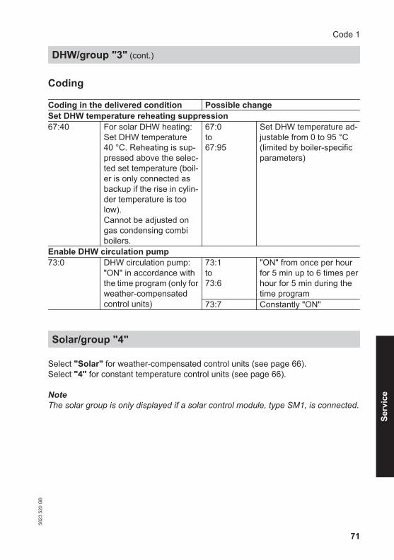
DHW/group "3"
Select "DHW" for weather-compensated control units (see page 66).Select "3" for constant temperature control units (see page 66).
Code 1
Boiler/group "2"
5623
520
GB
71
Coding
Coding in the delivered condition Possible changeSet DHW temperature reheating suppression67:40 For solar DHW heating:
Set DHW temperature40 °C. Reheating is sup-pressed above the selec-ted set temperature (boil-er is only connected asbackup if the rise in cylin-der temperature is toolow).Cannot be adjusted ongas condensing combiboilers.
67:0to67:95
Set DHW temperature ad-justable from 0 to 95 °C(limited by boiler-specificparameters)
Enable DHW circulation pump73:0 DHW circulation pump:
"ON" in accordance withthe time program (only forweather-compensatedcontrol units)
73:1to73:6
"ON" from once per hourfor 5 min up to 6 times perhour for 5 min during thetime program
73:7 Constantly "ON"
Solar/group "4"
Select "Solar" for weather-compensated control units (see page 66).Select "4" for constant temperature control units (see page 66).
NoteThe solar group is only displayed if a solar control module, type SM1, is connected.
Code 1
DHW/group "3" (cont.)
5623
520
GB
Serv
ice

72
Coding
Coding in the delivered condition Possible changeSpeed control solar circuit pump02:0 Solar circuit pump is not
speed-controlled.02:1 Solar circuit pump is
speed-controlled withwave packet control.
02:2 Solar circuit pump isspeed-controlled withPWM control.
Cylinder maximum temperature08:60 Set DHW temperature
(maximum cylinder tem-perature) 60 °C.
08:10to08:90
Set DHW temperature ad-justable from 10 to 90 °C.
Stagnation time reduction0A:5 Temperature differential
for stagnation time reduc-tion (reduction in thespeed of the solar circuitpump to protect systemcomponents and heattransfer medium) 5 K.
0A:0 Stagnation time reductiondisabled.
0A:1to0A:40
Temperature differentialadjustable from 1 to 40 K.
Flow rate solar circuit0F:70 Solar circuit flow rate at
the maximum pumpspeed 7 l/min.
0F:1to0F:255
Flow rate adjustable from0.1 to 25.5 l/min;1 step ≙ 0.1 l/min.
Code 1
Solar/group "4" (cont.)
5623
520
GB

73
Coding in the delivered condition Possible changeExtended solar control functions20:0 No extended control func-
tion enabled.20:1 Additional function for
DHW heating.20:2 Differential temperature
control 2.20:3 Differential temperature
control 2 and auxiliary func-tion.
20:4 Differential temperaturecontrol 2 for central heatingbackup.
20:5 Thermostat function.20:6 Thermostat function and
auxiliary function.20:7 Solar heating via external
heat exchanger without ad-ditional temperature sen-sor.
20:8 Solar heating via externalheat exchanger with addi-tional temperature sensor.
20:9 Solar heating of two DHWcylinders.
Heating circuit 1, heating circuit 2, heating circuit 3/group "5"
Select "Heating circuit ..." for weather-compensated control units (see page 66).Select "5" for constant temperature control units (see page 66).
Code 1
Solar/group "4" (cont.)
5623
520
GB
Serv
ice
74
Coding
Coding in the delivered condition Possible changePriority DHW heatingA2:2 Cylinder priority applica-
ble to heating circuitpump and mixer
A2:0 Without cylinder priority ap-plied to heating circuitpump and mixer
A2:1 Cylinder priority only appli-cable to mixer
A2:3toA2:15
Reduced priority applied tomixer (the heating circuitreceives a reduced amountof energy)
Economy function outside temperatureA5:5 With heating circuit pump
logic function (economymode): Heating circuitpump "OFF" when theoutside temperature (AT)is 1 K higher than the setroom temperature (RTset)AT > RTset + 1 K (only forweather-compensatedcontrol units)
A5:0 Without heating circuitpump logic function
A5:1toA5:15
With heating circuit pumplogic function: Heating cir-cuit pump "OFF"; see fol-lowing table
Parameter addressA5:...
With heating circuit pump logic function: Heating cir-cuit pump "OFF"
1 AT > RTset + 5 K2 AT > RTset + 4 K3 AT > RTset + 3 K4 AT > RTset + 2 K5 AT > RTset + 1 K6 AT > RTset
7to
AT > RTset - 1 K
15 AT > RTset - 9 K
Code 1
Heating circuit 1, heating circuit 2, heating… (cont.)
5623
520
GB

75
Coding in the delivered condition Possible changeExtended economy function adjusted outside temperatureA6:36 Extended economy func-
tion disabled (only forweather-compensatedcontrol units)
A6:5toA6:35
Extended economy func-tion enabled, i.e. the burnerand heating circuit pumpwill stop and the mixerclose at a variable value,adjustable between 5 and35 °C plus 1 °C. The basevalue is the adjusted out-side temperature. This val-ue is based on the actualoutside temperature and atime constant, which takesthe cooling down of anaverage building into con-sideration.
Extended economy function mixerA7:0 Without mixer economy
function (only for a weath-er-compensated controlunit and heating circuitwith mixer)
A7:1 With mixer economy func-tion (extended heating cir-cuit pump logic): Heating circuit pump also"OFF":■ If the mixer has been at-
tempting to close for lon-ger than 20 min.
Heating circuit pump"ON":■ If the mixer changes to
control function■ If there is a risk of frost
Pump idle time, transition reduced mode A9:7 With pump idle time:
Heating circuit pump"OFF" if the set value isaltered through a changein operating mode orthrough a change in theset room temperature(only for weather-com-pensated control units)
A9:0 Without pump idle timeA9:1toA9:15
With pump idle time, ad-justable from 1 to 15. Thehigher the value, the longerthe pump idle time.
Code 1
Heating circuit 1, heating circuit 2, heating… (cont.)
5623
520
GB
Serv
ice

76
Coding in the delivered condition Possible changeWeather-compensated/room temperature hook-upb0:0 With remote control:
Heating mode/reducedmode: weather-compen-sated (only for weather-compensated controlunits; only change thecode for the heating cir-cuit with mixer)
b0:1 Heating mode: weather-compensatedReduced mode: with roomtemperature hook-up
b0:2 Heating mode: with roomtemperature hook-upReduced mode: weather-compensated
b0:3 Heating mode/reducedmode: with room tempera-ture hook-up
Economy function room temperatureb5:0 With remote control: No
room temperature-de-pendent heating circuitpump logic function (onlyfor weather-compensa-ted control units; onlychange the code for theheating circuit with mix-er)
b5:1tob5:8
Heating circuit pump logicfunction, see the followingtable:
Parameter ad-dress b5:...
With heating circuit pump logic function:Heating circuit pump "OFF" Heating circuit pump "ON"
1 RTactual > RTset + 5 K RTactual < RTset + 4 K2 RTactual > RTset + 4 K RTactual < RTset + 3 K3 RTactual > RTset + 3 K RTactual < RTset + 2 K4 RTactual > RTset + 2 K RTactual < RTset + 1 K5 RTactual > RTset + 1 K RTactual < RTset
6 RTactual > RTset RTactual < RTset - 1 K7 RTactual > RTset - 1 K RTactual < RTset - 2 K8 RTactual > RTset - 2 K RTactual < RTset - 3 K
Coding in the delivered condition Possible changeMin. flow temperature heating circuitC5:20 Electronic minimum flow
temperature limit 20 °C(only for weather-com-pensated control units)
C5:1toC5:127
Minimum limit adjustablefrom 1 to 127 °C (limited byboiler-specific parameters)
Code 1
Heating circuit 1, heating circuit 2, heating… (cont.)
5623
520
GB

77
Coding in the delivered condition Possible changeMax. flow temperature heating circuitC6:74 Electronic maximum flow
temperature limit 74 °C(only for weather-com-pensated control units)
C6:10toC6:127
Maximum limit adjustablefrom 10 to 127 °C (limitedby boiler-specific parame-ters)
Heating program - changeoverd5:0 The external heating pro-
gram changeoverchanges the heating pro-gram to "Constant opera-tion with reduced roomtemperature" or "Standbymode" (only for weather-compensated controlunits)
d5:1 The external heating pro-gram changeover changesto "Constant operation withstandard room tempera-ture" (subject to coding ad-dress 3A, 3b and 3C)
Ext. heating program changeover to heating circuitd8:0 No heating program
changeover via extensionEA1
d8:1 Heating program change-over via input DE1 at ex-tension EA1
d8:2 Heating program change-over via input DE2 at ex-tension EA1
d8:3 Heating program change-over via input DE3 at ex-tension EA1
Screed dryingF1:0 Screed drying function
disabled (only for weath-er-compensated controlunits).
F1:1toF1:6
Screed drying adjustable inaccordance with 6 selecta-ble temperature/time pro-files (see page 154)
F1:15 Constant flow temperature20 °C
Party mode time limitF2:8 Time limit for party mode
or external heating pro-gram changeover viapushbutton: 8 h (only forweather-compensatedcontrol units)*1
F2:0 No time limit for partymode*1
F2:1toF2:12
Time limit adjustable from 1to 12 h*1
*1 Party mode ends automatically in the "Heating and DHW" program, when thesystem changes over to operation with standard room temperature.
Code 1
Heating circuit 1, heating circuit 2, heating… (cont.)
5623
520
GB
Serv
ice

78
Coding in the delivered condition Possible changePump control in only DHW modeF6:25 In the "Only DHW" oper-
ating mode, the circula-tion pump in the heatingcircuit connection set ispermanently on (only forconstant temperaturecontrol units)
F6:0 In the "Only DHW" operat-ing mode, the circulationpump in the heating circuitconnection set is perma-nently off
F6:1toF6:24
In the "Only DHW" operat-ing mode, the circulationpump in the heating circuitconnection set will be star-ted 1 to 24 times per day for10 min each time.
Pump control in standby modeF7:25 In the "Standby" operat-
ing mode, the circulationpump in the heating cir-cuit connection set is per-manently on (only forconstant temperaturecontrol units)
F7:0 In the "Standby" operatingmode, the circulation pumpin the heating circuit con-nection set is permanentlyoff
F7:1toF7:24
In the "Standby" operatingmode, the circulation pumpin the heating circuit con-nection set will be started 1to 24 times per day for10 min each time.
Start temperature raisingF8:-5 Temperature limit for ter-
minating the reducedmode -5 ºC; see exampleon page 157.Observe the setting ofcoding address "A3". (on-ly for weather-compensa-ted control units)
F8:+10toF8:-60
Temperature limit adjusta-ble from +10 to -60 °C
F8:-61 Function disabled
End temperature raisingF9:-14 Temperature limit for rais-
ing the reduced set roomtemperature -14 ºC; seeexample on page 157.(only for weather-com-pensated control units)
F9:+10toF9:-60
Temperature limit for rais-ing the set room tempera-ture to the value selectedfor standard mode adjusta-ble from+10 to -60 °C
Code 1
Heating circuit 1, heating circuit 2, heating… (cont.)
5623
520
GB

79
Coding in the delivered condition Possible changeSet flow temperature increaseFA:20 Raising the set boiler wa-
ter temperature or the setflow temperature whenchanging from operationwith reduced room tem-perature to operation withstandard room tempera-ture, by 20 %. See exam-ple on page 158 (only forweather-compensatedcontrol units).
FA:0toFA:50
Temperature rise adjusta-ble from 0 to 50 %
Duration set flow temperature increaseFb:30 Duration for raising the
set boiler water tempera-ture or the set flow tem-perature (see coding ad-dress "FA") 60 min. Seeexample on page 158(only for weather-com-pensated control units).
Fb:0toFb:150
Duration adjustable from 0to 300 min;1 step ≙ 2 min
Code 1
Heating circuit 1, heating circuit 2, heating… (cont.)
5623
520
GB
Serv
ice

80
Calling up coding level 2
Note■ At coding level 2, all codes are acces-
sible, including the codes at codinglevel 1.
■ Codes that have not been assigneddue to the heating system equipmentlevel or the setting of other codes arenot displayed.
■ Heating systems with one heating cir-cuit without mixer and one or two heat-ing circuits with mixer:The heating circuit without mixer isdesignated "Heating circuit 1" andthe heating circuits with mixer as"Heating circuit 2" or "Heating cir-cuit 3".If the heating circuits were given indi-vidual designations, the selected des-ignation and "HC1", "HC2" or "HC3"appear instead.
Weather-compensated control unit:
1. Press OK and å simultaneouslyfor approx. 4 s.
2. Press OK and ä simultaneously forapprox. 4 s.
3. "Coding level 2"
4. Select group of required codingaddress:■ "General"■ "Boiler"■ "DHW"■ "Solar"■ "Heating circuit 1/2/3"■ "All codes std device"
In this group, all coding addresses(except the coding addresses fromthe "Solar" group) are displayed inascending order.
5. Select coding address.
6. Select value according to the follow-ing tables and confirm with "OK".
7. If you want to reset all codes totheir delivered condition:Select "Standard setting" in "Cod-ing level 2".
NoteThis also resets codes at coding level1.
Constant temperature control unit:
1. Press OK and å simultaneouslyfor approx. 4 s.
2. Press OK and ä simultaneously forapprox. 4 s.
3. Select "2" with Ú for coding level 2and confirm with OK."I" flashes on the display for the cod-ing addresses in category 1.
Code 2
Calling up coding level 2
5623
520
GB

81
4. Select the group for the required cod-ing address with V/v:1: "General"2: "Boiler"3: "DHW"4: "Solar"5: "Heating circuit 1"6: "All codes std device"
In this group, all coding addressesare displayed in ascending order.
Confirm selected category with OK.
5. Select coding address with V/v.
6. Set value according to the followingtables with V/v and confirm withOK.
7. If you want to reset all codes totheir delivered condition:Select "7" with Ú and confirm withOK.When " " flashes, confirm with OK.
NoteThis also resets codes at coding level1.
General/group "1"
Select "General" for weather-compensated control units (see page 80).Select "1" for constant temperature control units (see page 80).
Coding
Coding in the delivered condition Possible change00:1 System version 1:
One heating circuit with-out mixer A1 (heating cir-cuit 1), without DHWheating
00:2to00:10
For system schemes, seethe following table:
Valueaddress00: ...
Systemversion
Description
2 1 One heating circuit without mixer A1 (heating circuit 1), withDHW heating (code is adjusted automatically)
3 2.3 One heating circuit with mixer M2 (heating circuit 2), withoutDHW heating
4 2.3 One heating circuit with mixer (heating circuit 2), with DHWheating
5 4 One heating circuit without mixer A1 (heating circuit 1) andone heating circuit with mixer M2 (heating circuit 2), withoutDHW heating (code is adjusted automatically)
Code 2
Calling up coding level 2 (cont.)
5623
520
GB
Serv
ice

82
Valueaddress00: ...
Systemversion
Description
6 4 One heating circuit without mixer A1 (heating circuit 1) andone heating circuit with mixer M2 (heating circuit 2), with DHWheating (code is adjusted automatically)
7 4 One heating circuit with mixer M2 (heating circuit 2) and oneheating circuit with mixer M3 (heating circuit 3), without DHWheating
8 4 One heating circuit with mixer M2 (heating circuit 2) and oneheating circuit with mixer M3 (heating circuit 3), with DHWheating
9 4 One heating circuit without mixer A1 (heating circuit 1), oneheating circuit with mixer M2 (heating circuit 2) and one heat-ing circuit with mixer M3 (heating circuit 3), without DHWheating (code is adjusted automatically)
10 4 One heating circuit without mixer A1 (heating circuit 1), oneheating circuit with mixer M2 (heating circuit 2) and one heat-ing circuit with mixer M3 (heating circuit 3), with DHW heating(code is adjusted automatically)
Coding in the delivered condition Possible change11:≠9 No access to the coding
addresses for the com-bustion controller param-eters
11:9 Access open to the codingaddresses for the combus-tion controller parameters
25:0 Without outside tempera-ture sensor (for constanttemperature controlunits)
25:1 With outside temperaturesensor (automatic recogni-tion)
2A:0 Without wireless outsidetemperature sensor
2A:1 With wireless outside tem-perature sensor (automaticrecognition)
2A:2 Wireless outside tempera-ture sensor not used
2d:1 With flow sensors (do notadjust)
32:0 Without extension AM1 32:1 With extension AM1 (auto-matic recognition)
33:1 Function output A1 at ex-tension AM1: Heating cir-cuit pump
33:0 Function output A1: DHWcirculation pump
Code 2
General/group "1" (cont.)
5623
520
GB

83
Coding in the delivered condition Possible change33:2 Function output A1: Circu-
lation pump for cylinderheating
34:0 Function output A2 at ex-tension AM1: DHW circu-lation pump
34:1 Function output A2: Heat-ing circuit pump
34:2 Function output A2: Circu-lation pump for cylinderheating
35:0 Without extension EA1 35:1 With extension EA1 (auto-matic recognition)
36:0 Function, output aBJ atextension EA1: Faultmessage
36:1 Function output aBJ: Feedpump
36:2 Function output aBJ: DHWcirculation pump
39:2 Function output sA: Cir-culation pump for cylinderheating
39:0 Function output sA: DHWcirculation pump
39:1 Function output sA: Heat-ing circuit pump
3A:0 Function input DE1 at ex-tension EA1: Not as-signed
3A:1 Function input DE1: Heat-ing program - changeover
3A:2 Function input DE1: Exter-nal demand with set flowtemperature.Flow temperature setting:Coding address 9b.Internal circulation pumpfunction: Coding address3F
3A:3 Function input DE1: Exter-nal blocking.Internal circulation pumpfunction: Coding address3E
3A:4 Function input DE1: Exter-nal blocking with fault mes-sage inputInternal circulation pumpfunction: Coding address3E
3A:5 Function input DE1: Faultmessage input
Code 2
General/group "1" (cont.)
5623
520
GB
Serv
ice

84
Coding in the delivered condition Possible change3A:6 Function input DE1: Brief
operation, DHW circulationpump (pushbutton func-tion).DHW circulation pump run-time adjustment: Codingaddress 3d
3b:0 Function input DE2 at ex-tension EA1: Not as-signed
3b:1 Function input DE2: Heat-ing program - changeover
3b:2 Function input DE2: Exter-nal demand with set flowtemperature.Flow temperature setting:Coding address 9b.Internal circulation pumpfunction: Coding address3F
3b:3 Function input DE2: Exter-nal blocking.Internal circulation pumpfunction: Coding address3E
3b:4 Function input DE2: Exter-nal blocking with fault mes-sage inputInternal circulation pumpfunction: Coding address3E
3b:5 Function input DE2: Faultmessage input
3b:6 Function input DE2: Briefoperation, DHW circulationpump (pushbutton func-tion).DHW circulation pump run-time adjustment: Codingaddress 3d
3C:0 Function input DE3 at ex-tension EA1: Not as-signed
3C:1 Function input DE3: Heat-ing program - changeover
Code 2
General/group "1" (cont.)
5623
520
GB

85
Coding in the delivered condition Possible change3C:2 Function input DE3: Exter-
nal demand with set flowtemperature.Flow temperature setting:Coding address 9b.Internal circulation pumpfunction: Coding address3F
3C:3 Function input DE3: Exter-nal blocking.Internal circulation pumpfunction: Coding address3E
3C:4 Function input DE3: Exter-nal blocking with fault mes-sage inputInternal circulation pumpfunction: Coding address3E
3C:5 Function input DE3: Faultmessage input
3C:6 Function input DE3: Briefoperation, DHW circulationpump (pushbutton func-tion).DHW circulation pump run-time adjustment: Codingaddress 3d
3d:5 DHW circulation pumpruntime for brief opera-tion: 5 min
3d:1to3d:60
DHW circulation pump run-time adjustable from 1 to60 min
3E:0 Boiler circuit pump staysin control mode on "Ex-ternal blocking" signal
3E:1 Boiler circuit pump is stop-ped on "External blocking"signal
3E:2 Boiler circuit pump is star-ted on "External blocking"signal
3F:0 Boiler circuit pump staysin control mode on "Ex-ternal demand" signal
3F:1 Boiler circuit pump is stop-ped on "External demand"signal
Code 2
General/group "1" (cont.)
5623
520
GB
Serv
ice

86
Coding in the delivered condition Possible change3F:2 Boiler circuit pump is star-
ted on "External demand"signal
4b:0 Function input lH: Roomthermostat (Vitotrol 100)for constant temperaturecontrol
4b:1 External demand4b:2 External blocking
51:0 System with low lossheader: Boiler circuit pump is al-ways started when thereis a heat demand
51:1 System with low loss head-er: When there is heat de-mand, the boiler circuitpump will only be started ifthe burner is running.Circulation pump is switch-ed off when run-on time ex-pires.
51:2 System with heating waterbuffer cylinder: When there is heat de-mand, the boiler circuitpump will only be started ifthe burner is running.Circulation pump is switch-ed off when run-on time ex-pires.
52:0 Without flow temperaturesensor for low loss head-er
52:1 With flow temperature sen-sor for low loss header (au-tomatic recognition)
53:1 Function connection sKof the internal extension:DHW circulation pump
53:0 Function connection sK:Central fault message
53:2 Function connection sK:External heating circuitpump (heating circuit 1)
53:3 Function connection sK:External circulation pumpfor cylinder heating
54:0 Without solar thermalsystem
54:1 With Vitosolic 100 (auto-matic recognition)
54:2 With Vitosolic 200 (auto-matic recognition)
Code 2
General/group "1" (cont.)
5623
520
GB

87
Coding in the delivered condition Possible change54:3 With solar control module
SM1 without auxiliary func-tion (automatic recogni-tion)
54:4 With solar control moduleSM1 with auxiliary function,e.g. central heating backup(automatic recognition)
6E:50 No correction of meas-ured outside tempera-ture
6E:0to6E:100
Outside temperature cor-rection in 0.1 K steps0 to 49 = -5 K to -0.1 K51 to 100 = 0.1 K to 5 K
76:0 Without communicationmodule
76:1 With LON communicationmodule (recognised auto-matically; only for weather-compensated controlunits)
76:2 With cascade communica-tion module (recognisedautomatically; only for con-stant temperature controlunits)
77:1 LON subscriber number(only for weather-com-pensated control units)
77:2to77:99
LON subscriber number,adjustable from 1 to 99:1 - 4 = Boiler5 = Cascade10 - 97 = Vitotronic 200-H98 = Vitogate99 = Vitocom
NoteAllocate each number onlyonce.
79:1 With LON communicationmodule: Control unit isfault manager (only forweather-compensatedcontrol units)
79:0 Control unit is not faultmanager
Code 2
General/group "1" (cont.)
5623
520
GB
Serv
ice

88
Coding in the delivered condition Possible change7b:1 With LON communication
module: Control unittransmits the time (onlyfor weather-compensa-ted control units)
7b:0 Does not transmit time
7F:1 Detached house (only forweather-compensatedcontrol units)
7F:0 Apartment buildingSeparate adjustment ofholiday program and timeprogram for DHW heatingpossible.
80:6 If a fault occurs for at least30 s, a fault message isdisplayed
80:0 Immediate fault message80:2to80:199
Minimum fault duration un-til fault message occurs,adjustable from 10 s to995 s; 1 step ≙ 5 s
81:1 Automatic summer/win-tertime changeover
81:0 Manual summer/winter-time changeover
81:2 Use of the radio clock re-ceiver (automatic recogni-tion)
81:3 With LON communicationmodule: The control unit re-ceives the time
82:0 Operation with naturalgas
82:1 Operation with LPG (onlyadjustable if coding ad-dress 11:9 has been set)
88:0 Temperature display in°C (Celsius)
88:1 Temperature display in °F(Fahrenheit)
8A:175 Do not adjust. 8F:0 Operation in the standard
menu and extendedmenu enabled.
NoteThe respective code isonly activated when youexit the service menu.
8F:1 Operation in the standardmenu and extended menublocked.Emissions test mode canbe enabled.
8F:2 Operation enabled in thestandard menu; blocked inthe extended menu.Emissions test mode canbe enabled.
Code 2
General/group "1" (cont.)
5623
520
GB

89
Coding in the delivered condition Possible change90:128 Time constant for calcu-
lating the adjusted out-side temperature 21.3 h
90:1to90:199
Fast (low values) or slow(high values) matching ofthe flow temperature, sub-ject to the set value whenthe outside temperaturechanges;1 step ≙ 10 min
94:0 Without Open Therm ex-tension
94:1 With Open Therm exten-sion (automatic recogni-tion)
95:0 Without Vitocom 100communication interface
95:1 With Vitocom 100 commu-nication interface (auto-matic recognition)
97:0 With LON communicationmodule: The outside tem-perature of the sensorconnected to the controlunit is utilised internally(only for weather-com-pensated control units)
97:1 Control unit receives out-side temperature
97:2 Control unit transmits theoutside temperature to theVitotronic 200-H
98:1 Viessmann system num-ber (in conjunction withmonitoring several sys-tems via Vitocom 300)
98:1to98:5
System number adjustablefrom 1 to 5
99:0 Do not adjust 9A:0 Do not adjust 9b:70 Set flow temperature for
external demand 70 °C9b:0to9b:127
Set flow temperature forexternal demand adjusta-ble from 0 to 127 °C (limitedby boiler-specific parame-ters)
9C:20 Monitoring LON subscrib-ers.
9C:0 No monitoring9C:5to
Time adjustable from 5 to60 min
Code 2
General/group "1" (cont.)
5623
520
GB
Serv
ice

90
Coding in the delivered condition Possible changeIf a subscriber fails to re-spond, the values speci-fied inside the control unitwill be used after 20 min.Only then will a fault mes-sage be issued. (only forweather-compensatedcontrol units)
9C:60
9F:8 Differential temperature8 K; only in conjunctionwith mixer circuit (only forweather-compensatedcontrol units)
9F:0to9F:40
Differential temperatureadjustable from 0 to 40 K
Boiler/group "2"
Select "Boiler" for weather-compensated control units (see page 80).Select "2" for constant temperature control units (see page 80).
Coding
Coding in the delivered condition Possible change01:1 Single boiler system (only
for constant temperaturecontrol units)
01:2 Multi boiler system withVitotronic 300-K
04:1 Minimum burner pausesubject to the boiler load(specified by boiler cod-ing card)
04:0 Minimum burner pause setpermanently (specified byboiler coding card)
06:... Maximum limit of the boil-er water temperature,specified in °C by the boil-er coding card
06:20to06:127
Maximum limit of the boilerwater temperature withinthe ranges specified by theboiler
07:1 Boiler number in multiboiler systems (only forconstant temperaturecontrol units)
07:2to07:8
Boiler number 2 to 8 in mul-ti boiler systems
Code 2
General/group "1" (cont.)
5623
520
GB

91
Coding in the delivered condition Possible change08:... Maximum burner heating
output in kW in the caseof a multi boiler system
08:0to08:199
Maximum burner heatingoutput adjustable from 0 to199 kW (limited by boiler-specific parameters) insteps of 1 kW
0d:0 Do not adjust 0E:0 Do not adjust 13:1 Do not adjust 14:1 Do not adjust 15:1 Do not adjust 21:0 No service interval (hours
run) selected21:1to21:100
Number of hours run be-fore the burner should beserviced is adjustable from100 to 10,000 hOne adjusting step ≙100 h
23:0 No time interval for burn-er service
23:1to23:24
Interval adjustable from 1to 24 months
24:0 No "Service" display 24:1 "Service" display (the ad-dress is automatically setand must be manually re-set after a service has beencarried out)
28:0 No burner interval igni-tion
28:1to28:24
Interval adjustable from 1 hto 24 h. The burner is force-started once every 30 s(only when operating withLPG).
2E:0 Do not adjust 2F:0 Venting program/fill pro-
gram disabled2F:1 Venting program enabled2F:2 Fill program enabled
30:3 Boiler circuit pump speedcontrolled via 0-10 V in-terface (do not adjust)
38:0 Status burner control unit:Operational (no fault)
38:≠0 Status burner control unit:Faults
Code 2
Boiler/group "2" (cont.)
5623
520
GB
Serv
ice

92
Select "DHW" for weather-compensated control units (see page 80).Select "3" for constant temperature control units (see page 80).
Coding
Coding in the delivered condition Possible change56:0 Set DHW temperature
adjustable from 10 to60 °C
56:1 Set DHW temperature ad-justable from 10 to over60 °C
NoteMaximum value subject toboiler coding card.Observe the max. permis-sible DHW temperature.
58:0 Without auxiliary functionfor DHW heating
58:10to58:60
Input of a second set DHWtemperature, adjustablefrom 10 to 60 °C (observecoding addresses "56" and"63")
59:0 Cylinder heating:Starting point -2.5 KStopping point +2.5 K
59:1to59:10
Starting point adjustablefrom 1 to 10 K below the setvalue
5b:0 DHW cylinder directlyconnected to the boiler
5b:1 DHW cylinder connecteddownstream of the low lossheader
5E:0 Circulation pump for cyl-inder heating stays incontrol mode at signal"External blocking"
5E:1 Circulation pump for cylin-der heating stops at signal"External blocking"
5E:2 Circulation pump for cylin-der heating starts at signal"External blocking"
5F:0 Circulation pump for cyl-inder heating stays incontrol mode at signal"External demand"
5F:1 Circulation pump for cylin-der heating stops at signal"External demand"
5F:2 Circulation pump for cylin-der heating starts at signal"External demand"
Code 2
DHW/group "3"
5623
520
GB

93
Coding in the delivered condition Possible change60:20 During DHW heating, the
boiler water temperatureis max. 20 K higher thanthe set DHW tempera-ture
60:5to60:25
The differential betweenthe boiler water tempera-ture and the set DHW tem-perature is adjustable from5 to 25 K
62:2 Circulation pump with2 min run-on time aftercylinder heating
62:0 Circulation pump withoutrun-on
62:1to62:15
Run-on time adjustablefrom 1 to 15 min
63:0 Without auxiliary functionfor DHW heating (only forconstant temperaturecontrol units)
63:1 Auxiliary function: 1 x daily63:2to63:14
Every 2 days to every 14days
63:15 2 x daily65:0 Do not adjust. 67:40 For solar DHW heating:
Set DHW temperature40 °C. Reheating is sup-pressed above the selec-ted set temperature (boil-er is only connected asbackup if the rise in cylin-der temperature is toolow).
67:0to67:95
Set DHW temperature ad-justable from 0 to 95 °C(limited by boiler-specificparameters)
6F:... Maximum output forDHW heating in %, speci-fied by the boiler codingcard
6F:0to6F:100
Max. output for DHW heat-ing adjustable from min.output to 100 %
71:0 DHW circulation pump:"ON" in accordance withthe time program (only forweather-compensatedcontrol units)
71:1 "OFF" during DHW heatingto set value 1
71:2 "ON" during DHW heatingto set value 1
72:0 DHW circulation pump:"ON" in accordance withthe time program (only forweather-compensatedcontrol units)
72:1 "OFF" during DHW heatingto set value 2
72:2 "ON" during DHW heatingto set value 2
Code 2
DHW/group "3" (cont.)
5623
520
GB
Serv
ice

94
Coding in the delivered condition Possible change73:0 DHW circulation pump:
"ON" in accordance withthe time program (only forweather-compensatedcontrol units)
73:1to73:6
"ON" from once per hourfor 5 min up to 6 times perhour for 5 min during thetime program
73:7 Constantly "ON"
Solar/group "4"
Select "Solar" for weather-compensated control units (see page 80).Select "4" for constant temperature control units (see page 80).
NoteThe solar group is only displayed if a solar control module, type SM1, is connected.
Coding
Coding in the delivered condition Possible change00:8 Start temperature differ-
ential for solar circuitpump 8 K .
00:2to00:30
Start temperature differen-tial adjustable from 2 to30 K.
01:4 Stop temperature differ-ential for solar circuitpump 4 K.
01:1to01:29
Stop temperature differen-tial adjustable from 1 to29 K.
02:0 Solar circuit pump is notspeed-controlled.
02:1 Solar circuit pump isspeed-controlled withwave packet control.
02:2 Solar circuit pump isspeed-controlled withPWM control.
03:10 Temperature differentialfor the start of the speedcontrol 10 K.
03:5to03:20
Temperature differentialadjustable from 5 to 20 K.
04:4 Controller amplification ofthe speed control 4 %/K.
04:1to04:10
Controller amplification ad-justable from 1 to 10 %/K.
05:10 Minimum speed of the so-lar circuit pump 10 % ofthe maximum speed.
05:2to05:100
Minimum speed of the so-lar circuit pump is adjusta-ble from 2 to 100 %.
Code 2
DHW/group "3" (cont.)
5623
520
GB

95
Coding in the delivered condition Possible change06:75 Maximum speed of the
solar circuit pump 75 % ofthe maximum possiblespeed.
06:1to06:100
Maximum speed of the so-lar circuit pump is adjusta-ble from 1 to 100 %.
07:0 Interval function of the so-lar circuit pump switchedoff.
07:1 Interval function of the so-lar circuit pump switchedon.To capture the collectortemperature more accu-rately, the solar circuitpump starts for short cy-cles.
08:60 Set DHW temperature(maximum cylinder tem-perature) 60 °C.
08:10to08:90
Set DHW temperature ad-justable from 10 to 90 °C.
09:130 Maximum collector tem-perature (to protect thesystem components)130 °C.
09:20to09:200
Temperature adjustablefrom 20 to 200 °C.
0A:5 Temperature differentialfor stagnation time reduc-tion (reduction in thespeed of the solar circuitpump to protect systemcomponents and heattransfer medium) 5 K.
0A:0 Stagnation time reductionis disabled.
0A:1to0A:40
Temperature differentialadjustable from 1 to 40 K.
0b:0 Frost protection functionfor solar circuit switchedoff.
0b:1 Frost protection functionfor solar circuit switched on(not required withViessmann heat transfermedium).
0C:1 Delta T monitoringswitched on.No flow rate captured inthe solar circuit, or flowrate too low.
0C:0 Delta T monitoring switch-ed off.
0d:1 Night circulation monitor-ing switched on.Unintentional flow rate iscaptured in the solar cir-cuit (e.g. at night).
0d:0 Night circulation monitor-ing switched off.
Code 2
Solar/group "4" (cont.)
5623
520
GB
Serv
ice

96
Coding in the delivered condition Possible change0E:1 Heat statement in con-
junction with Viessmannheat transfer medium.
0E:2 Never adjust.0E:0 No heat statement.
0F:70 Solar circuit flow rate atthe maximum pumpspeed 7 l/min.
0F:1to0F:255
Flow rate adjustable from0.1 to 25.5 l/min.1 step ≙ 0.1 l/min
10:0 Target temperature con-trol switched off (see cod-ing address "11").
10:1 Target temperature controlswitched on.
11:50 Set solar DHW tempera-ture 50 °C.■ Target temperature
control switched on(code "10:1"):Temperature at whichthe solar heated waterin the DHW cylinder isto be stratified.
■ Code "20:9" (heating oftwo DHW cylinders) isselected:When one DHW cylin-der reaches its setDHW temperature, thesecond DHW cylinderis heated.
11:10to11:90
The set solar DHW temper-ature is adjustable from 10to 90 °C.
12:20 Minimum collector tem-perature (minimum starttemperature for the solarcircuit pump) 20 °C.
12:0 No minimum limit enabled.12:1to12:90
Minimum collector temper-ature adjustable from 1 to90 °C.
20:0 No extended control func-tions enabled.
20:1 Additional function forDHW heating.
20:2 Differential temperaturecontrol 2.
20:3 Differential temperaturecontrol 2 and auxiliary func-tion.
20:4 Differential temperaturecontrol 2 for central heatingbackup.
20:5 Thermostat function.
Code 2
Solar/group "4" (cont.)
5623
520
GB

97
Coding in the delivered condition Possible change20:6 Thermostat function and
auxiliary function.20:7 Solar heating via external
heat exchanger without ad-ditional temperature sen-sor.
20:8 Solar heating via externalheat exchanger with addi-tional temperature sensor.
20:9 Solar heating of two DHWcylinders.
22:8 Start temperature differ-ential with central heatingbackup (code "20:4" mustbe selected) 8 K.
22:2to22:30
Start temperature differen-tial adjustable from 2 to30 K.
23:4 Shutdown temperaturedifferential with centralheating backup (code"20:4" must be selected)4 K.
23:2to23:30
Shutdown temperature dif-ferential adjustable from 1to 29 K.
24:40 Start temperature forthermostat function (code"20:5" or "20:6" must beselected) 40 °C.
24:0to24:100
Start temperature for ther-mostat function adjustablefrom 0 to 100 K.
25:50 Shutdown temperaturefor thermostat function(code "20:5" or "20:6"must be selected) 50 °C.
25:0to25:100
Shutdown temperature forthermostat function adjust-able from 0 to 100 K.
26:1 Priority for DHW cylinder1 with alternate heating.(Code "20:9" must be se-lected).
26:0 Priority for DHW cylinder 1without alternate heating.
26:2 Priority for DHW cylinder 2without alternate heating.
26:3 Priority for DHW cylinder 2with alternate heating.
26:4 Alternate heating withoutpriority for either DHW cyl-inder.
27:15 Alternate heating time15 min.
27:5to27:60
The alternate heating timeis adjustable from 5 to60 min.
Code 2
Solar/group "4" (cont.)
5623
520
GB
Serv
ice

98
Coding in the delivered condition Possible changeThe DHW cylinder with-out priority is heated atmost for the duration ofthe set alternate heatingtime if the DHW cylinderwith priority is heated up.
28:3 Alternate pause time3 min.After the selected alter-nate heating time for theDHW cylinder without pri-ority has expired, the risein collector temperature iscaptured during the alter-nate pause time.
28:1to28:60
The alternate pause time isadjustable from 1 to60 min.
Heating circuit 1, heating circuit 2, heating circuit 3/group "5"
Select "Heating circuit ..." for weather-compensated control units (see page 80).Select "5" for constant temperature control units (see page 80).
Coding
Coding in the delivered condition Possible changeA0:0 Without remote control A0:1 With Vitotrol 200A/200RF
(automatic recognition)A0:2 With Vitotrol 300A/300RF
or Vitohome 300 (automat-ic recognition)
A1:0 All possible settings atthe remote control can beaccessed
A1:1 Only party mode can be setat the remote control (onlyfor Vitotrol 200 and200 RF)
A2:2 Cylinder priority applica-ble to heating circuitpump and mixer
A2:0 Without cylinder priority ap-plied to heating circuitpump and mixer
A2:1 Cylinder priority only appli-cable to mixer
Code 2
Solar/group "4" (cont.)
5623
520
GB

99
Coding in the delivered condition Possible changeA2:3toA2:15
Reduced priority applied tomixer (the heating circuitreceives a reduced amountof energy)
A3:2 Outside temperature be-low 1 °C: Heating circuitpump "ON"Outside temperatureabove 3 °C: Heating cir-cuit pump "OFF"
A3:-9toA3:15
Heating circuit pump "ON/OFF" (see following table)
! Please noteWhen selecting a value below 1 °C, there is a risk of pipes outside the thermalenvelope of the building freezing up.The standby mode in particular should be taken into consideration, e.g. duringholidays.
Parameter Heating circuit pump address A3:... "On" "Off"-9 -10 °C -8 °C-8 -9 °C -7 °C-7 -8 °C -6 °C-6 -7 °C -5 °C-5 -6 °C -4 °C-4 -5 °C -3 °C-3 -4 °C -2 °C-2 -3 °C -1 °C-1 -2 °C 0 °C0 -1 °C 1 °C1 0 °C 2 °C2to
1 °Cto
3 °Cto
15 14 °C 16 °C
Coding in the delivered condition Possible changeA4:0 With frost protection (only
for weather-compensa-ted control units).
A4:1 No frost protection; this set-ting is only possible if code"A3:-9" has been selected.
Code 2
Heating circuit 1, heating circuit 2, heating… (cont.)
5623
520
GB
Serv
ice

100
Coding in the delivered condition Possible changeNote"Important" observe forcode "A3".
A5:5 With heating circuit pumplogic function (economymode): Heating circuitpump "OFF" when theoutside temperature (AT)is 1 K higher than the setroom temperature (RTset)AT > RTset + 1 K (only forweather-compensatedcontrol units)
A5:0 Without heating circuitpump logic function
A5:1toA5:15
With heating circuit pumplogic function: Heating cir-cuit pump "OFF"; see fol-lowing table
Parameter addressA5:...
With heating circuit pump logic function: Heating cir-cuit pump "OFF"
1 AT > RTset + 5 K2 AT > RTset + 4 K3 AT > RTset + 3 K4 AT > RTset + 2 K5 AT > RTset + 1 K6 AT > RTset
7to
AT > RTset - 1 K
15 AT > RTset - 9 K
Code 2
Heating circuit 1, heating circuit 2, heating… (cont.)
5623
520
GB

101
Coding in the delivered condition Possible changeA6:36 Extended economy func-
tion disabled (only forweather-compensatedcontrol units)
A6:5toA6:35
Extended economy func-tion enabled, i.e. the burnerand heating circuit pumpwill stop and the mixerclose at a variable value,adjustable between 5 and35 °C plus 1 °C. The basevalue is the adjusted out-side temperature. This val-ue is based on the actualoutside temperature and atime constant, which takesthe cooling down of anaverage building into con-sideration.
A7:0 Without mixer economyfunction (only for a weath-er-compensated controlunit and heating circuitwith mixer)
A7:1 With mixer economy func-tion (extended heating cir-cuit pump logic): Heating circuit pump also"OFF":■ If the mixer has been at-
tempting to close for lon-ger than 20 min.
Heating circuit pump"ON":■ If the mixer changes to
control function■ If there is a risk of frost
A8:1 Heating circuit with mixercreates a demand for theboiler circuit pump (onlyfor weather-compensa-ted control units)
A8:0 Heating circuit with mixercreates no demand for theboiler circuit pump
A9:7 With pump idle time:Heating circuit pump"OFF" if the set value isaltered through a changein operating mode orthrough a change in theset room temperature(only for weather-com-pensated control units)
A9:0 Without pump idle timeA9:1toA9:15
With pump idle time, ad-justable from 1 to 15. Thehigher the value, the longerthe pump idle time.
Code 2
Heating circuit 1, heating circuit 2, heating… (cont.)
5623
520
GB
Serv
ice

102
Coding in the delivered condition Possible changeb0:0 With remote control:
Heating mode/reducedmode: weather-compen-sated (only for weather-compensated controlunits; only change thecode for the heating cir-cuit with mixer)
b0:1 Heating mode: weather-compensatedReduced mode: with roomtemperature hook-up
b0:2 Heating mode: with roomtemperature hook-upReduced mode: weather-compensated
b0:3 Heating mode/reducedmode: with room tempera-ture hook-up
b2:8 With remote control unitand for the heating circuit,operation with room tem-perature hook-up must beprogrammed: Room influ-ence factor 8 (only forweather-compensatedcontrol units; change thecode only for the heatingcircuit with mixer)
b2:0 Without room influenceb2:1tob2:64
Room influence factor ad-justable from 1 to 64. Thehigher the value, the great-er the room influence.
b5:0 With remote control: Noroom temperature-de-pendent heating circuitpump logic function (onlyfor weather-compensa-ted control units; onlychange the code for theheating circuit with mix-er)
b5:1tob5:8
Heating circuit pump logicfunction, see the followingtable:
Parameter ad-dress b5:...
With heating circuit pump logic function:Heating circuit pump "OFF" Heating circuit pump "ON"
1 RTactual > RTset + 5 K RTactual < RTset + 4 K2 RTactual > RTset + 4 K RTactual < RTset + 3 K3 RTactual > RTset + 3 K RTactual < RTset + 2 K4 RTactual > RTset + 2 K RTactual < RTset + 1 K5 RTactual > RTset + 1 K RTactual < RTset
6 RTactual > RTset RTactual < RTset - 1 K
Code 2
Heating circuit 1, heating circuit 2, heating… (cont.)
5623
520
GB

103
Parameter ad-dress b5:...
With heating circuit pump logic function:Heating circuit pump "OFF" Heating circuit pump "ON"
7 RTactual > RTset - 1 K RTactual < RTset - 2 K8 RTactual > RTset - 2 K RTactual < RTset - 3 K
Coding in the delivered condition Possible changeC5:20 Electronic minimum flow
temperature limit 20 °C(only for weather-com-pensated control units)
C5:1toC5:127
Minimum limit adjustablefrom 1 to 127 °C (limited byboiler-specific parameters)
C6:74 Electronic maximum flowtemperature limit 74 °C(only for weather-com-pensated control units)
C6:10toC6:127
Maximum limit adjustablefrom 10 to 127 °C (limitedby boiler-specific parame-ters)
d3:14 Heating curve slope =1.4
d3:2tod3:35
Heating curve slope adjust-able from 0.2 to 3.5 (seepage 58)
d4:0 Heating curve level = 0 d4:–13tod4:40
Heating curve level adjust-able from –13 to 40 (seepage 58)
d5:0 The external heating pro-gram changeoverchanges the heating pro-gram to "Constant opera-tion with reduced roomtemperature" or "Standbymode" (only for weather-compensated controlunits)
d5:1 The external heating pro-gram changeover changesto "Constant operation withstandard room tempera-ture" (subject to coding ad-dress 3A, 3b and 3C)
d6:0 Heating circuit pumpstays in control mode atsignal "External block-ing"
d6:1 Heating circuit pump stopsat signal "External block-ing" (subject to coding ad-dresses 3A, 3b and 3C)
d6:2 Heating circuit pump startsat signal "External block-ing" (subject to coding ad-dresses 3A, 3b and 3C)
d7:0 Heating circuit pumpstays in control mode atsignal "External de-mand"
d7:1 Heating circuit pump stopsat signal "External de-mand" (subject to codingaddresses 3A, 3b and 3C)
Code 2
Heating circuit 1, heating circuit 2, heating… (cont.)
5623
520
GB
Serv
ice

104
Coding in the delivered condition Possible changed7:2 Heating circuit pump starts
at signal "External de-mand" (subject to codingaddresses 3A, 3b and 3C)
d8:0 No heating programchangeover via extensionEA1
d8:1 Heating program change-over via input DE1 at ex-tension EA1
d8:2 Heating program change-over via input DE2 at ex-tension EA1
d8:3 Heating program change-over via input DE3 at ex-tension EA1
E1:1 Do not adjust E2:50 With remote control: No
display correction for theactual room temperature(only for weather-com-pensated control units)
E2:0toE2:49
Display correction –5 KtoDisplay correction –01 K
E2:51toE2:99
Display correction +0.1 KtoDisplay correction +4.9 K
E5:0 Do not adjust F1:0 Screed drying function
disabled (only for weath-er-compensated controlunits).
F1:1toF1:6
Screed drying adjustable inaccordance with 6 selecta-ble temperature/time pro-files (see page 154)
F1:15 Constant flow temperature20 °C
F2:8 Time limit for party modeor external heating pro-gram changeover viapushbutton: 8 h (only forweather-compensatedcontrol units)*1
F2:0 No time limit for partymode*1
F2:1toF2:12
Time limit adjustable from 1to 12 h*1
F5:12 Run-on time of the boilercircuit pump in heatingmode: 12 min (only forconstant temperaturecontrol units)
F5:0 No boiler circuit pump run-on time
F5:1toF5:20
Run-on time of the boilercircuit pump adjustablefrom 1 to 20 min
*1 Party mode ends automatically in the "Heating and DHW" program, when thesystem changes over to operation with standard room temperature.
Code 2
Heating circuit 1, heating circuit 2, heating… (cont.)
5623
520
GB

105
Coding in the delivered condition Possible changeF6:25 In "Only DHW" operating
mode, the boiler circuitpump is permanently on(only for constant temper-ature control units)
F6:0 In "Only DHW" operatingmode, the boiler circuitpump is permanently off
F6:1toF6:24
In "Only DHW" operatingmode, the boiler circuitpump is started 1 to 24times per day for 10 mineach time.
F7:25 In "Standby mode", theboiler circuit pump is per-manently on (only forconstant temperaturecontrol units)
F7:0 In "Standby mode", theboiler circuit pump is per-manently off
F7:1toF7:24
In "Standby mode", theboiler circuit pump is star-ted 1 to 24 times per day for10 min each time.
F8:-5 Temperature limit for ter-minating the reducedmode -5 ºC; see exampleon page 157.Observe the setting ofcoding address "A3". (on-ly for weather-compensa-ted control units)
F8:+10toF8:-60
Temperature limit adjusta-ble from +10 to -60 °C
F8:-61 Function disabled
F9:-14 Temperature limit for rais-ing the reduced set roomtemperature -14 ºC; seeexample on page 157(only for weather-com-pensated control units).
F9:+10toF9:-60
Temperature limit for rais-ing the set room tempera-ture to the value selectedfor standard mode adjusta-ble from+10 to -60 °C
FA:20 Raising the set boiler wa-ter temperature or the setflow temperature whenchanging from operationwith reduced room tem-perature to operation withstandard room tempera-ture, by 20 %. See exam-ple on page 158 (only forweather-compensatedcontrol units).
FA:0to
Temperature rise adjusta-ble from 0 to 50 %
Code 2
Heating circuit 1, heating circuit 2, heating… (cont.)
5623
520
GB
Serv
ice

106
Coding in the delivered condition Possible changeFA:50
Fb:30 Duration for raising theset boiler water tempera-ture or the set flow tem-perature (see coding ad-dress "FA") 60 min. Seeexample on page 158(only for weather-com-pensated control units).
Fb:0toFb:150
Duration adjustable from 0to 300 min;1 step ≙ 2 min)
Code 2
Heating circuit 1, heating circuit 2, heating… (cont.)
5623
520
GB

107
Weather-compensated control unit
Press OK and å simultaneously forapprox. 4 s.
Service menu overview
Service
Diagnosis
Actuator test
Coding level 1
Brief scan
GeneralHeating circuit 1 HC1Heating circuit 2 HC2
DHWSolar
Enter Vitocom PIN code
Subscriber checkService PIN
Heating circuit 3 HC3
Coding level 2
Fault history
Service functions
Terminate service?
Reset data
FillingVentingMax. output
Service reset
Multi-boiler system
NoteDo not adjust menu item "Multi-boilersystem".The menu item turns a weather-compen-sated control unit into a constant tem-perature control unit.
Exiting the service level
1. Select "Terminate service?".
2. Select "Yes".
3. Confirm with OK.
NoteThe service level is automatically exi-ted after 30 min.
Constant temperature control unit
1. Press OK and å simultaneouslyfor approx. 4 s."Ü" flashes on the display.
2. Select required function. See the fol-lowing pages.
Diagnosis and service scans
Calling up the service level56
23 5
20 G
B
Serv
ice

108
Exiting the service level
1. Select "Serv" 7 with Ú.
2. Confirm with OK."OFF" flashes.
3. Confirm with OK.
NoteThe service level is automatically exi-ted after 30 min.
Diagnosis
Calling up operating data
■ Weather-compensated control unit:Operating data can be called up in sixareas. See "Diagnosis" in the servicemenu overview.Operating data on heating circuits withmixers and solar can only be called upif the components are installed in thesystem.For further information on operatingdata, see chapter "Brief scan".
■ Constant temperature control unit:Operating data can be called up in the"i" menu.
Operating instructions
For further information on operatingdata, see chapter "Brief scan".
Calling up operating data
Note"- - -" appears on the display if a sensorthat has been scanned is faulty.
Weather-compensated control unit
1. Press OK and å simultaneouslyfor approx. 4 s.
2. "Diagnosis"
3. Select required group, e.g. "Gen-eral".
Diagnosis and service scans
Calling up the service level (cont.)
5623
520
GB

109
Constant temperature control unit
Operating instructions, chapter"Calling up information"
Resetting operating data
Saved operating data (e.g. hours run)can be reset to 0. The value "Adjusted outside temp" isreset to the actual value.
Weather-compensated control unit
1. Press OK and å simultaneouslyfor approx. 4 s.
2. "Diagnosis"
3. "Reset data"
4. Select required value (e.g. "Burnerstarts") or "All details".
Constant temperature control unit
Operating instructions, chapter"Calling up information"
Brief scan
In the brief scan, you can call up tem-peratures, software versions and con-nected components, for example.
Weather-compensated control unit
1. Press OK and å simultaneouslyfor approx. 4 s.
2. "Diagnosis"
3. "Brief scan".
4. Press OK. The display shows 9 lines with 6 fieldseach.
Diagnosis Brief scan
2:1:
3:4:
Select with Ø
0001 F
000 0
000 A
000 0
001 2
000
Diagnosis and service scans
Diagnosis (cont.)
5623
520
GB
Serv
ice

110
For an explanation of the relevant values in the individual lines and fields, seethe following table:Line (briefscan)
Field
1 2 3 4 5 61: System scheme 01
to 10Software versionControl unit
Software versionProgramming unit
2: 0 0 Appliance version Device identificationZE-ID
3: 0 Number of KM BUSsubscribers
Software version, solarcontrol module SM1
4: Software versionBurner control unit
TypeBurner control unit
Burner control unit ver-sion
5: Internal details for calibration 0 Softwareversion,exten-sion AM1
Softwareversion, ex-tensionEA1
6: 0 0 0 Flow ratesensorswitchingstate1: Flowrate toolow or novolumet-ric flow
0 0
7: LONSubnet address/sys-tem number
LONNode address
0
8: LONSBVTconfigu-ration
LONSoftwareversioncommu-nicationco-pro-cessor
LONNeuron chip softwareversion
Number of LON sub-scribers
Diagnosis and service scans
Diagnosis (cont.)
5623
520
GB

111
Line (briefscan)
Field
1 2 3 4 5 69: Heating circuit A1
(without mixer)Heating circuit M2(with mixer)
Heating circuit M3(with mixer)
Remotecontrol0: without1: Vitotrol200/200A/200 RF2: Vitotrol300/300A/300 RForVitohome
SoftwareversionRemotecontrol
Remotecontrol0: with-out1: Vitotrol200/200A/200 RF2: Vitotrol300/300A/300 RForVitohome
SoftwareversionRemotecontrol
Remotecontrol0: with-out1: Vitotrol200/200A/200 RF2: Vitotrol300/300A/300 RForVitohome
Softwareversion Re-mote con-trol
10:(only forKM BUScirculationpumps)
Internal circulationpump
Heating circuitpump, heating cir-cuit M2
Heating circuit pump,heating circuit M3
Variablespeedpump0: With-out1: Wilo2: Grund-fos
Softwareversion,variablespeedpump0: No var-iablespeedpump
Variablespeedpump0: With-out1: Wilo2: Grund-fos
SoftwareversionVariablespeedpump0: No var-iablespeedpump
Variablespeedpump0: With-out1: Wilo2: Grund-fos
SoftwareversionVariablespeedpump0: No varia-ble speedpump
11: 0 0 SoftwareversionMixer ex-tensionheatingcircuitM20: Nomixer ex-tension
0 SoftwareversionMixer ex-tensionheatingcircuitM30: Nomixer ex-tension
0
Diagnosis and service scans
Diagnosis (cont.)
5623
520
GB
Serv
ice

112
Constant temperature control unit
1. Press OK and å simultaneouslyfor approx. 4 s."Ü" flashes on the display.
2. Confirm with OK.
3. Select the required scan with V/v.For example, "b" for "Max. output"(see following table):
4. Confirm selected scan with OK.
For explanations of individual scans, see the following table:Brief scan Display
0 Systemscheme 1to 2
Software versionControl unit
SoftwareversionProgram-ming unit
1 Adjusted outside temperature3 Set boiler water temperature4 Common demand temperature5 Set cylinder temperature6 Number of KM BUS sub-
scribersNumber of LON subscrib-ers
7 SNVT con-figuration0: Auto1: Tool
Software versionCommunications co-pro-cessor
Software versionLON module
8 Subnet address/systemnumber
Node address
9 Burner control unit type Appliance typeA Diverter
valve sta-tus0: Notavailable1: Heating2: Centralposition3: DHWheating
Flow rate1: Flow ratetoo low or novolumetricflow
Max. heating output in %
b Boiler coding card (hexadecimal)c Flow rate (specified in l/h)
Diagnosis and service scans
Diagnosis (cont.)
5623
520
GB

113
Brief scan Display
C VersionAppliance
VersionBurner control unit
d 0 0E1
SoftwareversionSolar con-trol mod-ule, typeSM1
Software versionBurner control unit
SoftwareversionCascademodule
F1
Code 53setting
Internal details for calibration
Extension AM1F2
Softwareversion
Output A1configura-tion(value corre-sponds tocode 33 set-ting)
Output A1switchingstate0: OFF1: ON
Output A2configura-tion(value cor-responds tocode 34 set-ting)
Output A2switchingstate0: OFF1: ON
Extension EA1F3
Output 157configura-tion(value cor-respondsto setting ofcoding ad-dress 36 ingroup 1"General")
Output 157switchingstate0: OFF1: ON
Input DE1switchingstate0: Open1: Closed
Input DE2switchingstate0: Open1: Closed
Input DE3switchingstate0: Open1: Closed
F4
Softwareversion
External hook-up 0 - 10 VDisplay in %
Solar control module SM1F5
Stagnation time of the solar thermal system in h
F6
Night circulation, solar thermal system (number)
F7
Differential temperature monitoring
Diagnosis and service scans
Diagnosis (cont.)
5623
520
GB
Serv
ice

114
Brief scan Display
F8
Solar cen-tral heatingbackup0: Disabled1: Enabled
Output 22switchingstate0: OFF1: ON
Open Therm extension (if installed)F9
Softwareversion
DHW heat-ing status
External hook-up 0 - 10 VDisplay in %
Checking outputs (relay test)
Weather-compensated control unit
1. Press OK and å simultaneouslyfor approx. 4 s.
2. "Actuator test"
The following relay outputs can be controlled subject to system design:Display ExplanationAll actuators Off All actuators are offBase load On Burner operated at minimum output; circulation
pump is startedFull load On Burner operated at maximum output; circulation
pump is startedOutput, internal On Output sÖ active (boiler circuit pump)Output 21/28 On Output sA active (circulation pump for cylinder heat-
ing)Htg circ pumpHC2
On Heating circuit pump output enabled (extension toheating circuit with mixer)
Mixer HC2 Open "Mixer open" output enabled (extension to heatingcircuit with mixer)
Mixer HC2 Close "Mixer close" output enabled (extension to heatingcircuit with mixer)
Htg circ pumpHC3
On Heating circuit pump output enabled (extension toheating circuit with mixer)
Diagnosis and service scans
Diagnosis (cont.)
5623
520
GB

115
Display ExplanationMixer HC3 Open "Mixer open" output enabled (extension to heating
circuit with mixer)Mixer HC3 Close "Mixer close" output enabled (extension to heating
circuit with mixer)Outp. int. exten.H1
On Output at internal extension enabled
AM1 output 1 On Output A1 at extension AM1 enabledAM1 output 2 On Output A2 at extension AM1 enabledEA1 output 1 On Contact P - S at plug aBJ of extension EA1 closedSolar circuitpump
On Solar circuit pump output sF on solar control moduleSM1 active
Solar circ pmpmin
On Solar circuit pump output on solar control moduleSM1 switched to minimum speed
Solar circ pmpmax
On Solar circuit pump output on solar control moduleSM1 switched to maximum speed
SM1 output 22 On Output sS on solar control module SM1 active
Constant temperature control unit
1. Press OK and å simultaneouslyfor approx. 4 s."Ü" flashes on the display.
2. Select " " with Ú and confirm withOK.
3. Select required actuator (output) withV/v (see following table):
4. Confirm selected actuator with OK.The display shows the number for theactivated actuator and "ON".
The following actuators (relay outputs) can be controlled subject to systemdesign:Display Explanation0 All actuators are off1 Burner operated at minimum output; circulation pump is started2 Burner operated at maximum output; circulation pump is star-
ted3 Output sÖ active (boiler circuit pump)10 Internal extension output enabled15 Solar circuit pump output sF on solar control module SM1 ac-
tive
Diagnosis and service scans
Checking outputs (relay test) (cont.)
5623
520
GB
Serv
ice

116
Display Explanation16 Solar circuit pump output on solar control module SM1 switched
to minimum speed17 Solar circuit pump output on solar control module SM1 switched
to maximum speed18 Output sS on solar control module SM1 active19 Contact P - S at plug aBJ of extension EA1 closed20 Output A1 at extension AM1 enabled21 Output A2 at extension AM1 enabled22 Output sA active (circulation pump for cylinder heating)
Diagnosis and service scans
Checking outputs (relay test) (cont.)
5623
520
GB

117
Weather-compensated control unit
In the event of a fault, red fault indicatorA flashes. " " flashes on the displayand "Fault" is shown.
R
bar
A
The fault code is displayed with OK. Foran explanation of the fault code, see thefollowing pages.For some faults, the type of fault is alsodisplayed in plain text.
Acknowledging a fault
Follow the instructions on the display.
NoteThe fault message is transferred to thestandard menu.A fault message facility, if connected, willbe switched OFF.If an acknowledged fault is not remedied,the fault message will be re-displayedthe following day and the fault messagefacility restarted.
Calling up acknowledged faults
Select "Fault" in the standard menu.The current faults will be displayed in alist.
Calling up fault codes from the faultmemory (fault history)
The 10 most recent faults (includingresolved ones) are saved and can becalled up.Faults are sorted by date.
1. Press OK and å simultaneouslyfor approx. 4 s.
2. "Fault history"
3. "Display?"
Troubleshooting
Fault display56
23 5
20 G
B
Serv
ice

118
Constant temperature control unit
In the event of a fault, red fault indicatorA flashes. The two-digit fault code and(subject to the type of fault) " " or " "flash on the programming unit display.
R
bar
A
Other current faults can be displayedwith / . For an explanation of the faultcodes, see the following pages.
1 5 0
ã
Example: Fault code "50"
Acknowledge a fault
Press OK; the standard display is shownagain.
A fault message facility, if connected, willbe switched OFF.If an acknowledged fault is not remedied,the fault message will be re-displayedthe following day and the fault messagefacility restarted.
Calling up acknowledged faults
Press OK for approx. 4 s. The 10 most recent faults (includingresolved ones) are saved and can becalled up.
Calling up fault codes from the faultmemory (fault history)
The 10 most recent faults (includingthose remedied) are saved and can becalled up.Faults are sorted by date.
1. Press OK and å simultaneouslyfor approx. 4 s.
2. Select "ã" and activate fault historywith OK.
3. Select fault messages with / .
Deleting fault history
While the list is displayed, press OK until flashes. Confirm with OK.
Troubleshooting
Fault display (cont.)
5623
520
GB
119
Dis-playedfaultcode
Const. Weath.-comp.
System char-acteristics
Cause Measures
10 X X Regulates as ifthe outsidetemperaturewere 0 °C
Short circuit,outside tem-perature sen-sor
Check outside tem-perature sensor(see page 135).
18 X X Regulates as ifthe outsidetemperaturewere 0 °C
Lead break,outside tem-perature sen-sor
Check outside tem-perature sensor(see page 135).
19 X X Regulates as ifthe outsidetemperaturewere 0 °C
Communica-tion interrup-tion, outsidetemperaturesensor RF(outside tem-perature sen-sor RF, KMBUS to wire-less base sta-tion, wirelessbase stationor wireless re-peater faultyor defective).
Check wirelessconnection (placeoutside tempera-ture sensor RF andwireless repeaterclose to the boil-er).Check KM BUS towireless base sta-tion.Log off outsidetemperature sen-sor and wirelessrepeater, then logthem on again.
Wirelessbase sta-tion
Replace outsidetemperature sen-sor RF.Replace wirelessrepeater.Replace wirelessbase station.
1 A X X Burner blocked Flow sensor 1faulty
Replace sensor(see page 138).
Troubleshooting
Fault codes56
23 5
20 G
B
Serv
ice

120
Dis-playedfaultcode
Const. Weath.-comp.
System char-acteristics
Cause Measures
1b X X Burner blocked Flow sensor 2faulty
Replace sensor(see page 138).
1F X X Burner blocked Differentialflow rate toolarge
Clean heat ex-changer by flush-ing.
20 X X Regulates with-out flow tem-perature sen-sor (low lossheader)
Short circuit,system flowtemperaturesensor
Check low lossheader sensor (seepage 136).
28 X X Regulates with-out flow tem-perature sen-sor (low lossheader)
Lead break,system flowtemperaturesensor
Check low lossheader sensor (seepage 136).If no low loss head-er sensor is con-nected, set code52:0.
30 X X Burner blocked Short circuit,boiler watertemperaturesensor
Check boiler watertemperature sen-sors (seepage 136).
38 X X Burner blocked Lead break,boiler watertemperaturesensor
Check boiler watertemperature sen-sors (seepage 136).
40 X Mixer closes Short circuit,flow tempera-ture sensor,heating circuit2 (with mixer)
Check flow temper-ature sensor (seepage 142).
44 X Mixer closes Short circuit,flow tempera-ture sensor,heating circuit3 (with mixer)
Check flow temper-ature sensor (seepage 142).
Troubleshooting
Fault codes (cont.)
5623
520
GB

121
Dis-playedfaultcode
Const. Weath.-comp.
System char-acteristics
Cause Measures
48 X Mixer closes Lead break,flow tempera-ture sensor,heating circuit2 (with mixer)
Check flow temper-ature sensor (seepage 142).
4C X Mixer closes Lead break,flow tempera-ture sensor,heating circuit3 (with mixer)
Check flow temper-ature sensor (seepage 142).
50 X X No DHW heat-ing by the boil-er
Short circuit,cylinder tem-perature sen-sor
Check the cylindertemperature sen-sor (seepage 136).
58 X X No DHW heat-ing
No DHWheating by theboiler
Check the cylindertemperature sen-sor (seepage 136).
90 X X Control mode Short circuit,temperaturesensor /
Check sensor /on solar controlmodule.
91 X X Control mode Short circuit,temperaturesensor aÖ
Check sensor aÖon solar controlmodule.
92 X X No solar DHWheating
Short circuit,collector tem-perature sen-sor
Check temperaturesensor & on solarcontrol module orsensor on theVitosolic.
93 X X Control mode Short circuit,cylinder tem-perature sen-sor
Check temperaturesensor at connec-tion S3 to theVitosolic.
94 X X No solar DHWheating
Short circuit,cylinder tem-perature sen-sor
Check temperaturesensor % on solarcontrol module orsensor on theVitosolic.
Troubleshooting
Fault codes (cont.)
5623
520
GB
Serv
ice

122
Dis-playedfaultcode
Const. Weath.-comp.
System char-acteristics
Cause Measures
98 X X Control mode Lead break,temperaturesensor /
Check sensor /on solar controlmodule.
99 X X Control mode Lead break,temperaturesensor aÖ
Check sensor aÖon solar controlmodule.
9 A X X No solar DHWheating
Lead break,collector tem-perature sen-sor
Check temperaturesensor & on solarcontrol module orsensor on theVitosolic.
9b X X Control mode Lead break,cylinder tem-perature sen-sor
Check temperaturesensor at connec-tion S3 to theVitosolic.
9C X X No solar DHWheating
Lead break,cylinder tem-perature sen-sor
Check temperaturesensor % on solarcontrol module orsensor on theVitosolic.
9E X X Control mode No flow ratein solar circuitor flow ratetoo low, ortemperaturelimiter has re-sponded
Check solar circuitpump and solar cir-cuit. Acknowledgefault message.
9F X X Control mode Solar controlmodule orVitosolic faul-ty
Replace solar con-trol module orVitosolic.
A3 X Burner blocked Flue gas tem-perature sen-sor not posi-tioned cor-rectly.
Install flue gas tem-perature sensorcorrectly (seepage 139).
Troubleshooting
Fault codes (cont.)
5623
520
GB

123
Dis-playedfaultcode
Const. Weath.-comp.
System char-acteristics
Cause Measures
A4 X Control mode Max. systempressure ex-ceeded
Check systempressure (max.system pressure6 bar).Check the functionand sizing of the di-aphragm expan-sion vessel.Vent the heatingsystem.
A7 X Control modeas per deliv-ered condition
Programmingunit faulty
Replace program-ming unit.
b0 X X Burner blocked Short circuit,flue gas tem-perature sen-sor
Check flue gastemperature sen-sor.
b1 X X Control modeas per deliv-ered condition
Communica-tion fault, pro-grammingunit
Check connectionsand replace pro-gramming unit if re-quired.
b5 X X Control modeas per deliv-ered condition
Internal fault Replace the controlunit.
b7 X X Burner blocked Boiler codingcard faulty
Plug in boiler cod-ing card or replaceif faulty.
b8 X X Burner blocked Lead break,flue gas tem-perature sen-sor
Check flue gastemperature sen-sor.
bA X Mixer regulatesto 20°C flowtemperature
Communica-tion error, ex-tension kit forheating circuit2 (with mixer)
Check extensionkit connections andcode.
Troubleshooting
Fault codes (cont.)
5623
520
GB
Serv
ice

124
Dis-playedfaultcode
Const. Weath.-comp.
System char-acteristics
Cause Measures
bb X Mixer regulatesto 20°C flowtemperature
Communica-tion error, ex-tension kit forheating circuit3 (with mixer)
Check extensionkit connections andcode.
bC X Control modewithout remotecontrol
Communica-tion error, re-mote controlVitotrol heat-ing circuit 1(without mix-er)
Check connec-tions, cable, codingaddress "A0" in"Heating circuit"group and remotecontrol DIPswitches. For wireless re-mote control units:Check radio pathconnections, placeremote control unitand wireless re-peater close to theboiler. Check KMBUS connection towireless base sta-tion. Replace wire-less components.
Troubleshooting
Fault codes (cont.)
5623
520
GB

125
Dis-playedfaultcode
Const. Weath.-comp.
System char-acteristics
Cause Measures
bd X Control modewithout remotecontrol
Communica-tion error, re-mote controlVitotrol heat-ing circuit 2(with mixer)
Check connec-tions, cable, codingaddress "A0" in"Heating circuit"group and remotecontrol unit setting.For wireless re-mote control units:Check radio pathconnections, placeremote control unitand wireless re-peater close to theboiler. Check KMBUS connection towireless base sta-tion. Replace wire-less components.
bE X Control modewithout remotecontrol
Communica-tion error, re-mote controlVitotrol heat-ing circuit 3(with mixer)
Check connec-tions, cable, codingaddress "A0" in"Heating circuit"group and remotecontrol unit setting.For wireless re-mote control units:Check radio pathconnections, placeremote control unitand wireless re-peater close to theboiler. Check KMBUS connection towireless base sta-tion. Replace wire-less components.
Troubleshooting
Fault codes (cont.)
5623
520
GB
Serv
ice

126
Dis-playedfaultcode
Const. Weath.-comp.
System char-acteristics
Cause Measures
bF X Control mode IncorrectLON commu-nication mod-ule
Replace LON com-munication mod-ule.
C1 X X Control mode Communica-tion fault, ex-tension EA1
Check connec-tions.
C2 X X Control mode Communica-tion error, so-lar controlmodule orVitosolic
Check solar controlmodule orVitosolic.
C3 X X Control mode Communica-tion fault, ex-tension AM1
Check connec-tions
C4 X X Control mode Communica-tion error,Open Thermextension
Check OpenTherm extension.
Cd X X Control mode Communica-tion error,Vitocom 100(KM BUS)
Check connec-tions, Vitocom 100and coding ad-dress "95" in group"General"/1.
CF X Control mode Communica-tion error,LON commu-nication mod-ule
Replace LON com-munication module
d6 X X Control mode Input DE1 re-ports a fault atextensionEA1
Remove fault atappliance con-cerned
d7 X X Control mode Input DE2 re-ports a fault atextensionEA1
Remove fault atappliance con-cerned.
Troubleshooting
Fault codes (cont.)
5623
520
GB
127
Dis-playedfaultcode
Const. Weath.-comp.
System char-acteristics
Cause Measures
d8 X X Control mode Input DE3 re-ports a fault atextensionEA1
Remove fault atappliance con-cerned.
dA X Control modewithout roominfluence
Short circuit,room temper-ature sensor,heating circuit1 (withoutmixer)
Check room tem-perature sensor,heating circuit 1.
db X Control modewithout roominfluence
Short circuit,room temper-ature sensor,heating circuit2 (with mixer)
Check room tem-perature sensor,heating circuit 2.
dC X Control modewithout roominfluence
Short circuit,room temper-ature sensor,heating circuit3 (with mixer)
Check room tem-perature sensor,heating circuit 3.
dd X Control modewithout roominfluence
Lead break,room temper-ature sensor,heating circuit1 (withoutmixer)
Check room tem-perature sensor forheating circuit 1and remote controlsettings.
dE X Control modewithout roominfluence
Lead break,room temper-ature sensor,heating circuit2 (with mixer)
Check room tem-perature sensor forheating circuit 2and remote controlsettings.
dF X Control modewithout roominfluence
Lead break,room temper-ature sensor,heating circuit3 (with mixer)
Check room tem-perature sensor forheating circuit 3and remote controlsettings.
Troubleshooting
Fault codes (cont.)
5623
520
GB
Serv
ice

128
Dis-playedfaultcode
Const. Weath.-comp.
System char-acteristics
Cause Measures
E0 X Control mode Fault externalLON sub-scriber
Check connectionsand LON subscrib-ers.
E1 X X Burner in a faultstate
Ionisationcurrent toohigh duringcalibration
Check gap be-tween ionisationelectrode andburner gauze as-sembly (seepage 46).In open flue mode,prevent very dustyconditions for thecombustion air.Press reset buttonR.
E2 X X Burner in a faultstate
Heating waterflow rate toolow duringcalibration.Flow limitercaused shut-down.
Ensure adequatecirculation volume.Check flow limiter. Remove scaling,blockage.Press reset buttonR.
E3 X X Burner in a faultstate
Heat transfertoo low duringcalibration.Temperaturelimiter causedshutdown.
Ensure adequateheat transfer.Press reset buttonR.
E4 X X Burner blocked Fault, supplyvoltage 24 V
Replace controlunit.
E5 X X Burner blocked Fault, flameamplifier
Replace controlunit.
Troubleshooting
Fault codes (cont.)
5623
520
GB

129
Dis-playedfaultcode
Const. Weath.-comp.
System char-acteristics
Cause Measures
E7 X X Burner in a faultstate
Ionisationcurrent toolow duringcalibration
Check ionisationelectrode:■ Distance to burn-
er gauze assem-bly (see page 46)
■ Contamination ofelectrode
■ Connecting leadand plug-in con-nections
Check flue system;remedy flue gas re-circulation if re-quired.Press reset buttonR.
E8 X X Burner in a faultstate
The ionisa-tion currentlies outsidethe permissi-ble range
Check gas supply(gas pressure andgas flow limiter),gas train and con-necting lead.Check allocation ofgas type (seepage 37).
Check ionisationelectrode:■ Distance to burn-
er gauze assem-bly (see page 46)
■ Contamination ofelectrode
Press reset buttonR.
Troubleshooting
Fault codes (cont.)
5623
520
GB
Serv
ice
130
Dis-playedfaultcode
Const. Weath.-comp.
System char-acteristics
Cause Measures
EA X X Burner in a faultstate
Ionisationcurrent out-side permissi-ble range dur-ing calibration(deviationfrom previouslevel toogreat)
Check flue system;remedy flue gas re-circulation if re-quired.In open flue mode,prevent very dustyconditions for thecombustion air.Press reset buttonR.Following severalunsuccessful resetattempts, replaceboiler coding cardand press resetbutton R.
Eb X X Burner in a faultstate
Repeatedflame lossduring cali-bration
Check gap be-tween ionisationelectrode andburner gauze as-sembly (seepage 46).Check allocation ofgas type (seepage 37).Check flue system;remedy flue gas re-circulation if re-quired.Press reset buttonR.
EC X X Burner in a faultstate
Parameterfault duringcalibration
Press reset buttonRor Replace boiler cod-ing card and pressreset button R.
Ed X X Burner in a faultstate
Internal fault Replace controlunit.
Troubleshooting
Fault codes (cont.)
5623
520
GB
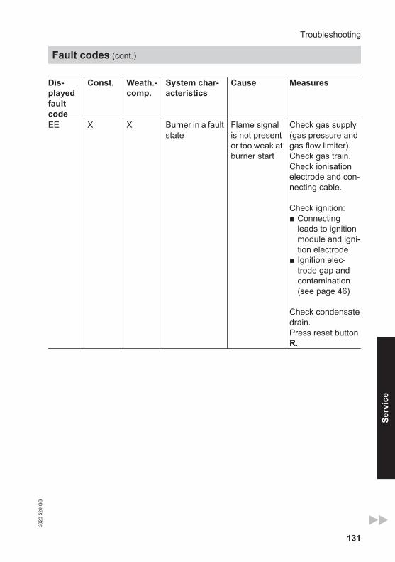
131
Dis-playedfaultcode
Const. Weath.-comp.
System char-acteristics
Cause Measures
EE X X Burner in a faultstate
Flame signalis not presentor too weak atburner start
Check gas supply(gas pressure andgas flow limiter). Check gas train.Check ionisationelectrode and con-necting cable.
Check ignition:■ Connecting
leads to ignitionmodule and igni-tion electrode
■ Ignition elec-trode gap andcontamination(see page 46)
Check condensatedrain.Press reset buttonR.
Troubleshooting
Fault codes (cont.)
5623
520
GB
Serv
ice

132
Dis-playedfaultcode
Const. Weath.-comp.
System char-acteristics
Cause Measures
EF X X Burner in a faultstate
Flame is lostimmediatelyafter it hasbuilt (duringthe safetytime)
Check gas supply(gas pressure andgas flow limiter).Check flue gas/ventilation air sys-tem for flue gas re-circulation.
Check ionisationelectrode (replaceif required):■ Distance to burn-
er gauze assem-bly (see page 46)
■ Contamination ofelectrode
Press reset buttonR.
F0 X X Burner blocked Internal fault Replace controlunit.
F1 X X Burner in a faultstate
Flue gas tem-perature hasexceededlimit
Check heating sys-tem fill level. Ventthe system. Press reset buttonR after flue systemhas cooled down.
F2 X X Burner in a faultstate
Boiler watertemperaturesensor hasresponded
Check heating sys-tem fill level. Checkcirculation pump.Vent the system.Check boiler watertemperature sen-sor and connectingcables. Press reset buttonR.
Troubleshooting
Fault codes (cont.)
5623
520
GB

133
Dis-playedfaultcode
Const. Weath.-comp.
System char-acteristics
Cause Measures
F3 X X Burner in a faultstate
Flame signalis alreadypresent atburner start
Check ionisationelectrode and con-necting cable. Press reset buttonR.
F6 X X Burner in a faultstate
Boiler watertemperaturesensor tem-perature val-ues vary toowidely fromone another
Replace boiler wa-ter temperaturesensors.
F8 X X Burner in a faultstate
Fuel valvecloses toolate
Check gas train.Check both controlpaths.Press reset buttonR.
F9 X X Burner in a faultstate
Fan speedtoo low duringburner start
Check fan, fan con-necting cables andpower supply;check fan control.Press reset buttonR.
FA X X Burner in a faultstate
Fan not atstandstill
Check fan, fan con-necting cables andfan control.Press reset buttonR.
FC X X Burner in a faultstate
Gas train faul-ty, faulty mod-ulation valvecontrol or fluegas pathblocked
Check gas train.Check flue sys-tem.Press reset buttonR.
Troubleshooting
Fault codes (cont.)
5623
520
GB
Serv
ice

134
Dis-playedfaultcode
Const. Weath.-comp.
System char-acteristics
Cause Measures
Fd X X Burner in a faultstate and addi-tional fault b7 isdisplayed
Boiler codingcard is miss-ing
Insert the boilercoding card.Press reset buttonR.Replace controlunit if fault per-sists.
Fd X X Burner in a faultstate
Fault, burnercontrol unit
Check ignitionelectrodes andconnecting cables.Check whether astrong interference(EMC) field existsnear the appliance.
Press reset buttonR.Replace controlunit if fault per-sists.
FE X X Burner blockedor in a faultstate
Boiler codingcard or mainPCB faulty, orincorrect boil-er codingcard
Press reset buttonR. If the fault per-sists, check theboiler coding cardor replace it or thecontrol unit.
FF X X Burner blockedor in a faultstate
Internal faultor reset but-ton Rblocked
Start the applianceagain. Replace thecontrol unit if theappliance will notrestart.
Troubleshooting
Fault codes (cont.)
5623
520
GB
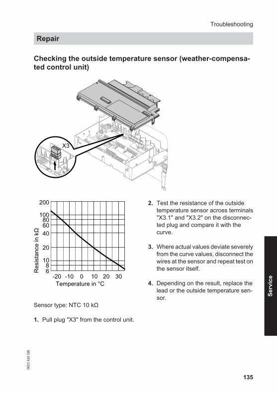
135
Checking the outside temperature sensor (weather-compensa-ted control unit)
X3
100
10
-20 -10 0 10 20 30Temperature in °C
68
20
406080
200
Res
ista
nce
in k
Ω
Sensor type: NTC 10 kΩ
1. Pull plug "X3" from the control unit.
2. Test the resistance of the outsidetemperature sensor across terminals"X3.1" and "X3.2" on the disconnec-ted plug and compare it with thecurve.
3. Where actual values deviate severelyfrom the curve values, disconnect thewires at the sensor and repeat test onthe sensor itself.
4. Depending on the result, replace thelead or the outside temperature sen-sor.
Troubleshooting
Repair56
23 5
20 G
B
Serv
ice

136
Checking the boiler water temperature sensors, cylinder tem-perature sensor or flow temperature sensor for the low lossheader
5
X3
§d{]A
Troubleshooting
Repair (cont.)
5623
520
GB

137
1. ■ Boiler water temperature sen-sorsRemove lead to boiler water tem-perature sensor § or §A andcheck the resistance.
■ Cylinder temperature sensorPull plug % from the cable har-ness at the control unit and checkthe resistance.
■ Flow temperature sensorPull plug "X3" from the control unitand check the resistance acrossterminals "X3.4" and "X3.5".
10
1
10 30 50 70 90 110Temperature in °C
0.40.60.8
2
468
20
Res
ista
nce
in k
Ω
Sensor type: NTC 10 kΩ
2. Check the sensor resistance andcompare the actual values with thecurve.
3. Replace the sensor in the case ofsevere deviation.
DangerThe boiler water temperaturesensors are immersed in theheating water (risk of scald-ing).Drain the boiler before replac-ing the sensor.
Troubleshooting
Repair (cont.)
5623
520
GB
Serv
ice

138
Replacing the flow rate sensor
A
NoteIn the event of a fault, both sensors needto be replaced.
1. Drain the boiler on the heating waterside.
2. Pull leads from flow rate sensor A.
3. Undo screws and remove faulty flowrate sensor A.
4. Install new flow rate sensor A andsecure with the screws.
Troubleshooting
Repair (cont.)
5623
520
GB

139
Checking the flue gas temperature sensor
The flue gas temperature sensor locks out the boiler when the permissible flue gastemperature is exceeded. Reset the interlock after the flue system has cooled downby pressing reset button R.
A 1. Pull leads from flue gas temperaturesensor A.
10
1
10 30 50 70 90 110Temperature in °C
0.40.60.8
2
468
20
Res
ista
nce
in k
Ω
Sensor type: NTC 10 kΩ
2. Check the sensor resistance andcompare it with the curve.
3. Replace the sensor in the case ofsevere deviation.
Fault during commissioning (fault A3)
During commissioning, the control unit checks correct placement of the flue gas tem-perature sensor. If commissioning is terminated and fault message A3 is displayed:
Troubleshooting
Repair (cont.)
5623
520
GB
Serv
ice

140
1. Check whether the flue gas temper-ature sensor is correctly inserted.See previous diagram.
2. If necessary, correct the position ofthe flue gas temperature sensor orreplace faulty flue gas temperaturesensor.
3. Press reset button R and repeat com-missioning.The check is repeated until it is com-pleted successfully.
Checking the fuse
F1A
1. Switch off the power.
2. Release the side closures and pivotthe control unit down.
3. Remove cover A.
4. Check fuse F1 (see connection andwiring diagram).
Troubleshooting
Repair (cont.)
5623
520
GB

141
Extension kit for heating circuit with mixer
Checking the setting of rotary selec-tor S1
The rotary selector on the PCB of theextension kit defines the assignment tothe relevant heating circuit.
Heating circuit Rotary se-lector S1 set-ting
Heating circuit with mix-er M2 (heating circuit2)
2 2 3 45
6
109 87
Heating circuit with mix-er M3 (heating circuit3)
4 42 3
56
109 87
Checking the rotational direction ofthe mixer motor
After being switched on, the boiler imple-ments a self-test. During this, the mixeris opened and closed again.
Note the rotational direction of the mixermotor during its self-test.Then set the mixer manually to "Open".
NoteThe flow temperature sensor must nowcapture a higher temperature. If the tem-perature drops, either the motor is turn-ing in the wrong direction or the mixer setis incorrectly fitted.
Mixer installation instructions
Changing the rotational direction of the mixer motor (if required)
gS
BU|
~
1. Remove the upper casing cover ofthe extension kit.
DangerAn electric shock can be life-threatening.Before opening the boiler, dis-connect from the mains volt-age, for example at the fuse orthe mains isolator.
2. At plug gS, swap the cores at termi-nals "|" and "~".
Troubleshooting
Repair (cont.)
5623
520
GB
Serv
ice

142
3. Refit the casing cover.
Check flow temperature sensor
Pressure drop curve
10
1
10 30 50 70 90 110Temperature in °C
0.40.60.8
2
468
20
Res
ista
nce
in k
Ω
Sensor type: NTC 10 kΩ
1. Pull plug ? (flow temperature sen-sor).
2. Check the sensor resistance andcompare it with the curve.Replace the sensor in the case ofsevere deviation.
Checking the Vitotronic 200-H (accessories)
The Vitotronic 200-H is connected to thecontrol unit via the LON. To test the con-nection, carry out a subscriber check atthe boiler control unit (see page 62).
Troubleshooting
Repair (cont.)
5623
520
GB
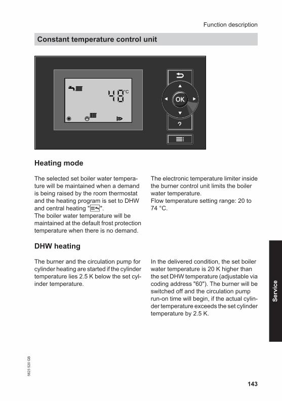
143
48°C
s A
Heating mode
The selected set boiler water tempera-ture will be maintained when a demandis being raised by the room thermostatand the heating program is set to DHWand central heating "G". The boiler water temperature will bemaintained at the default frost protectiontemperature when there is no demand.
The electronic temperature limiter insidethe burner control unit limits the boilerwater temperature.Flow temperature setting range: 20 to74 °C.
DHW heating
The burner and the circulation pump forcylinder heating are started if the cylindertemperature lies 2.5 K below the set cyl-inder temperature.
In the delivered condition, the set boilerwater temperature is 20 K higher thanthe set DHW temperature (adjustable viacoding address "60"). The burner will beswitched off and the circulation pumprun-on time will begin, if the actual cylin-der temperature exceeds the set cylindertemperature by 2.5 K.
Function description
Constant temperature control unit56
23 5
20 G
B
Serv
ice

144
48 °CBoiler temperature
HC1
14°C 21°C
Heating mode
The control unit determines a set boilerwater temperature subject to outsidetemperature or room temperature (if aroom temperature-dependent remotecontrol is connected) and to the slope/level of the heating curve. The determined set boiler water temper-ature is transferred to the burner controlunit. From the set and actual boiler watertemperatures, the burner control unit cal-culates the modulation level and regu-lates the burner accordingly.
The electronic temperature limiter insidethe burner control unit limits the boilerwater temperature.
DHW heating
The burner and the circulation pump forcylinder heating are started if the cylindertemperature lies 2.5 K below the set cyl-inder temperature.
In the delivered condition, the set boilerwater temperature is 20 K higher thanthe set DHW temperature (adjustable viacoding address "60" in group "DHW"/3).The burner will be switched off and thecirculation pump run-on time will begin,if the actual cylinder temperatureexceeds the set cylinder temperature by2.5 K.
Function description
Weather-compensated control unit
5623
520
GB

145
Boosting DHW heating
This function is activated by specifying asecond set DHW temperature via codingaddress 58 in group "DHW" and activat-ing the fourth DHW phase for DHW heat-ing.
Heating is boosted during the periodsselected in this time phase.
Internal extensions (accessories)
Internal extension H1
Function description
Weather-compensated control unit (cont.)
5623
520
GB
Serv
ice

146
The internal extension is integrated intothe control unit casing. The followingalternative functions can be connectedto relay output sK. The function isassigned via coding address "53" ingroup "General":■ Central fault message (code "53:0")■ DHW circulation pump (code "53:1")
(only for weather-compensated oper-ation)
■ Heating circuit pump for heating circuitwithout mixer (code "53:2")
■ Circulation pump for cylinder heating(code "53:3")
An external safety valve can be connec-ted to connection gD.
Internal extension H2
Function description
Internal extensions (accessories) (cont.)
5623
520
GB

147
The internal extension is integrated intothe control unit casing. The followingalternative functions can be connectedto relay output sK. The function isassigned via coding address "53" ingroup "General":■ Central fault message (code "53:0")■ DHW circulation pump (code "53:1")
(only for weather-compensated oper-ation)
■ Heating circuit pump for heating circuitwithout mixer (code "53:2")
■ Circulation pump for cylinder heating(code 53:3)
An extractor fan can be switched off viaconnection aBJ when the burner starts.
Function description
Internal extensions (accessories) (cont.)
5623
520
GB
Serv
ice
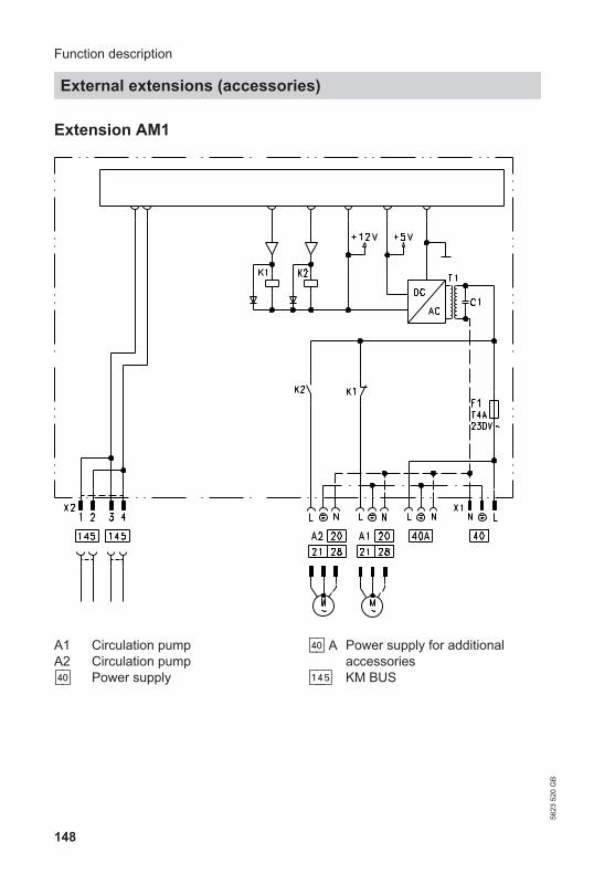
148
Extension AM1
A1 Circulation pumpA2 Circulation pumpfÖ Power supply
fÖ A Power supply for additionalaccessories
aVG KM BUS
Function description
External extensions (accessories)
5623
520
GB

149
Functions
One of the following circulation pumpscan be connected to each of the connec-tions A1 and A2:■ Heating circuit pump for the heating
circuit without mixer■ Circulation pump for cylinder heating■ DHW circulation pump
Select the output functions by means ofthe codes on the boiler control unit.
Function assignmentFunction Code ("General" group) Output A1 Output A2DHW circulation pump sK 33:0 34:0 (delivered
cond.)Heating circuit pump sÖ 33:1 (delivered
cond.)34:1
Circulation pump for cylinder heatingsA
33:2 34:2
Function description
External extensions (accessories) (cont.)
5623
520
GB
Serv
ice

150
Extension EA1
A1 PCBF1 FuseDE1 Digital input 1DE2 Digital input 2DE3 Digital input 30 – 10 V 0 - 10 V inputfÖ Power supply
fÖ A Power supply for additionalaccessories
aBJ Central fault message/feedpump/DHW circulation pump(potential-free)
aVG KM BUS
Function description
External extensions (accessories) (cont.)
5623
520
GB

151
Digital data inputs DE1 to DE3
The following functions can be connec-ted alternatively:■ External heating program changeover
for each heating circuit■ External blocking■ External blocking with fault message
input■ External demand with minimum boiler
water temperature■ Fault message input■ Brief operation of the DHW circulation
pump
External contacts must be floating.When connecting external contacts,observe the requirements of safety cat-egory II, i.e. 8.0 mm air and creep pathor 2.0 mm insulation thickness to 'live'parts.
Input function assignment
Select the input functions by means ofcodes in the "General" group at theboiler control unit:■ DE1: Coding address 3A■ DE2: Coding address 3b■ DE3: Coding address 3C
Assigning the heating programchangeover function to the heatingcircuits
Select the heating program changeoverfunction for the respective heating circuitvia coding address d8 in the "Heatingcircuit" group at the boiler control unit:■ Changeover via input DE1: Code d8:1■ Changeover via input DE2: Code d8:2■ Changeover via input DE3: Code d8:3
The effect of the heating programchangeover is selected via codingaddress d5 in the "Heating circuit"group. The duration of the changeover is set viacoding address F2 in the "Heating cir-cuit" group.
Effect of the external blocking func-tion on the pumps
The effect on the internal circulationpump is selected in coding address 3Ein the "General" group.The effect on the respective heating cir-cuit pump is selected in coding addressd6 in the "Heating circuit" group.The effect on a circulation pump for cyl-inder heating is selected in codingaddress 5E in the "DHW" group.
Effect of the external demand func-tion on the pumps
The effect on the internal circulationpump is selected in coding address 3F inthe "General" group.The effect on the respective heating cir-cuit pump is selected in coding addressd7 in the "Heating circuit" group.The effect on a circulation pump for cyl-inder heating is selected in codingaddress 5F in the "DHW" group.
DHW circulation pump runtime forbrief operation
The DHW circulation pump is started byclosing the contact at DE1, DE2 or DE3by means of a pushbutton. The runtimeis adjusted via coding address "3d" in the"General" group.
Function description
External extensions (accessories) (cont.)
5623
520
GB
Serv
ice

152
Analogue input 0 - 10 V
The 0 - 10 V hook-up provides an addi-tional set boiler water temperature:0 - 1 V taken as "no default for set boiler
water temperature"1 V ≙ set value 10 °C10 V ≙ set value 100 °CEnsure DC separation between the earthconductor and the negative pole of theon-site voltage source.
Output aBJ
The following functions can be connec-ted to output aBJ:■ Feed pump to substation
or■ DHW circulation pump
or■ Fault message facility
Function assignment
Select the function of output aBJ via cod-ing address "36" in the "General" groupat the boiler control unit.
Control functions
External heating program changeover
The "External heating program change-over" function is connected via extensionEA1. There are 3 inputs available atextension EA1 (DE1 to DE3).
The function is selected via the followingcoding addresses in the "General"group:
Heating program - changeover CodeInput DE1 3A:1Input DE2 3b:1Input DE3 3C:1
Select the heating program changeoverfunction for the respective heating circuitvia coding address "d8" in the "Heatingcircuit" group at the boiler control unit:
Heating program - changeover CodeChangeover via input DE1 d8:1Changeover via input DE2 d8:2Changeover via input DE3 d8:3
Function description
External extensions (accessories) (cont.)
5623
520
GB

153
You can select which direction the heat-ing program changeover takes in codingaddress "d5" in the "Heating circuit"group:
Heating program - changeover CodeChangeover towards "Permanently reduced" or "Permanentstandby" mode (subject to the selected set value)
d5:0
Changeover towards "Constant heating mode" d5:1
The duration of the heating programchangeover is set via coding address"F2" in the "Heating circuit" group:
Heating program - changeover CodeNo operating program changeover F2:0Duration of the operating program changeover 1 to 12 hours F2:1 to
F2:12
The operating program changeoverstays enabled for as long as the contactremains closed, but at least as long asthe duration selected in coding address"F2".
External blocking
The "External blocking" and "Externalblocking and fault message input" func-tions are connected via extension EA1.There are 3 inputs available at extensionEA1 (DE1 to DE3).
The function is selected via the followingcoding addresses in the "General"group:
External blocking CodeInput DE1 3A:3Input DE2 3b:3Input DE3 3C:3
Function description
Control functions (cont.)
5623
520
GB
Serv
ice

154
External blocking and fault message input CodeInput DE1 3A:4Input DE2 3b:4Input DE3 3C:4
The effect on the internal circulationpump is selected in coding address"3E" in the "General" group.
The effect on the respective heating cir-cuit pump is selected in coding address"d6" in the "Heating circuit" group.
External demand
The "External demand" function is con-nected via extension EA1. There are 3inputs available at extension EA1 (DE1to DE3).
The function is selected via the followingcoding addresses in the "General"group:
External demand CodeInput DE1 3A:2Input DE2 3b:2Input DE3 3C:2
The effect on the internal circulationpump is selected in coding address"3F" in the "General" group.The effect on the respective heating cir-cuit pump is selected in coding address"d7" in the "Heating circuit" group.
The minimum set boiler water tempera-ture in case of external demand is selec-ted in coding address "9b" in the "Gen-eral" group.
Venting program
During the venting program, the circula-tion pump will be alternately switched onand off for 30 s respectively over a periodof 20 min.
The burner is switched off during theventing program.Activate venting program: See "Ventingthe heating system".
Screed drying
When activating screed drying, observethe information provided by the screedmanufacturer.
Function description
Control functions (cont.)
5623
520
GB

155
When screed drying is activated, theheating circuit pump of the mixer circuitis switched on and the flow temperatureis held in accordance with the selectedprofile. After completion (30 days), themixer circuit will again be regulated auto-matically via the set parameters.Observe EN 1264. The report to be pro-vided by the heating contractor mustcontain the following heat-up details:■ Heat-up data with respective flow tem-
peratures■ Max. flow temperature achieved■ Operating conditions and outside tem-
perature during handover
The various temperature profiles can beset via coding address "F1" in the "Heat-ing circuit" group.The function continues after power fail-ure or after the control unit has beenswitched off. "Heating and DHW" is star-ted when screed drying is finished or ifcode "F1:0" is set manually.
Temperature profile 1: (EN 1264-4) code "F1:1"
Flow
tem
pera
ture
°C
1 5 10 15 20 25 30Days
5040302010
Temperature profile 2: (ZV parquet and flooring technology) code "F1:2"
Flow
tem
pera
ture
°C
Days
5040302010
1 5 10 15 20 25 30
Function description
Control functions (cont.)
5623
520
GB
Serv
ice

156
Temperature profile 3: Code "F1:3"
Flow
tem
pera
ture
°C
Days
5040302010
1 5 10 15 20 25 30
Temperature profile 4: Code "F1:4"
Flow
tem
pera
ture
°C
Days
5040302010
1 5 10 15 20 25 30
Temperature profile 5: Code "F1:5"
Flow
tem
pera
ture
°C
1 5 10 15 20 25 30Days
5040302010
Function description
Control functions (cont.)
5623
520
GB

157
Temperature profile 6: Code "F1:6"
Flow
tem
pera
ture
°C
1 5 10 15 20 25 30Days
5040302010
60
Temperature profile 7: Code "F1:15"
Flow
tem
pera
ture
°C
1 5 10 15 20 25 30Days
5040302010
Raising the reduced room temperature
During operation with reduced roomtemperature, the reduced set room tem-perature can be automatically raisedsubject to the outside temperature. Thetemperature is raised in accordance withthe selected heating curve, but no higherthan the set standard room tempera-ture.
The outside temperature limits for thestart and end of temperature raising canbe set in coding addresses "F8" and"F9" in the "Heating circuit" group.
Function description
Control functions (cont.)
5623
520
GB
Serv
ice

158
Example using the settings in the delivered condition
A
B
-20Outside temp. in °C
Boile
r wat
er o
rFl
ow te
mpe
ratu
re in
°C 80
70
60
50
40
30
0 -5 -10 -15510
Set room temperature in °C
3530
2520
1510
50
90
A Heating curve for operation withstandard room temperature
B Heating curve for operation withreduced room temperature
Reducing the heat-up time
During the transition from operation withreduced room temperature to operationwith standard room temperature, theboiler water or flow temperature will beraised in accordance with the selectedheating curve. The boiler water or flowtemperature can be automaticallyincreased.
The value and duration of the additionalincrease in the set boiler water or flowtemperature can be set in codingaddresses "FA" and "Fb" in the "Heatingcircuit" group.
Function description
Control functions (cont.)
5623
520
GB

159
Example using the settings in the delivered condition
10
0
20
3030
40
50
60
600 700 800 900
Set b
oile
r wat
er o
r flo
wte
mpe
ratu
re in
°C
Time in h
A
B
C
D
A Start of operation with standardroom temperature
B Set boiler water or flow temperaturein accordance with the selectedheating curve
C Set boiler water or flow temperaturein accordance with coding address"FA":50 °C + 20 % = 60 °C
D Duration of operation with raised setboiler water or flow temperature inaccordance with coding address"Fb":60 min
Function description
Control functions (cont.)
5623
520
GB
Serv
ice
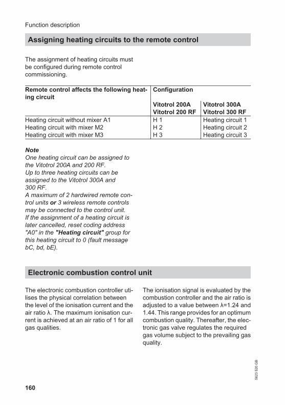
160
The assignment of heating circuits mustbe configured during remote controlcommissioning.
Remote control affects the following heat-ing circuit
Configuration
Vitotrol 200A Vitotrol 300A Vitotrol 200 RF Vitotrol 300 RFHeating circuit without mixer A1 H 1 Heating circuit 1Heating circuit with mixer M2 H 2 Heating circuit 2Heating circuit with mixer M3 H 3 Heating circuit 3
NoteOne heating circuit can be assigned tothe Vitotrol 200A and 200 RF.Up to three heating circuits can beassigned to the Vitotrol 300A and300 RF.A maximum of 2 hardwired remote con-trol units or 3 wireless remote controlsmay be connected to the control unit.If the assignment of a heating circuit islater cancelled, reset coding address"A0" in the "Heating circuit" group forthis heating circuit to 0 (fault messagebC, bd, bE).
Electronic combustion control unit
The electronic combustion controller uti-lises the physical correlation betweenthe level of the ionisation current and theair ratio λ. The maximum ionisation cur-rent is achieved at an air ratio of 1 for allgas qualities.
The ionisation signal is evaluated by thecombustion controller and the air ratio isadjusted to a value between λ=1.24 and1.44. This range provides for an optimumcombustion quality. Thereafter, the elec-tronic gas valve regulates the requiredgas volume subject to the prevailing gasquality.
Function description
Assigning heating circuits to the remote control
5623
520
GB

161
To check the combustion quality, theCO2 content or the O2 content of the fluegas is measured. The prevailing air ratiois determined with the measured values.The relationship between the CO2 or O2
content and air ratio λ is illustrated in thefollowing table.
Air ratio λ– CO2/O2 contentAir ratioλ
O2 content(%)
CO2 content (%)for natural gas
E
CO2 content (%)for natural gas
LL
CO2 content(%) for LPG P
1.20 3.8 9.6 9.2 11.31.24 4.4 9.2 9.1 10.91.27 4.9 9.0 8.9 10.61.30 5.3 8.7 8.6 10.31.34 5.7 8.5 8.4 10.01.37 6.1 8.3 8.2 9.81.40 6.5 8.1 8.0 9.61.44 6.9 7.8 7.7 9.31.48 7.3 7.6 7.5 9.0
To achieve an optimum combustion con-trol, the system regularly carries out anautomatic self-calibration; also after apower failure (shutdown). For this, thecombustion is briefly regulated to max.ionisation current (corresponding to airratio λ=1). Automatic calibration is car-ried out shortly after the burner start andlasts approx. 5 s. During calibration,higher than normal CO emissions mayoccur briefly.
Function description
Electronic combustion control unit (cont.)
5623
520
GB
Serv
ice

162
AA
X... Electrical interfaces§ (A/B) Boiler water temperature sen-
soraA Ionisation electrodeaG Flue gas temperature sensor
gF Ignition unita-Ö Fan motora-Ö A Fan motor controla:Ö Modulation coilA Flow rate sensor
Designs
Connection and wiring diagram – internal connections
5623
520
GB

163
A1 Main PCBA2 Power supply unitA3 Optolink
A4 Burner control unitA5 Programming unitA6 Coding card
Designs
Connection and wiring diagram – external connections56
23 5
20 G
B
Serv
ice

164
A7 Connection adaptorA8 LON communication module or
cascade communication moduleA9 Internal extension (accessories)S1 ON/OFF switchS2 Reset buttonX... Electrical interfaces! Outside temperature sensor? Flow temperature sensor, low loss
header% Cylinder temperature sensor
(plug on the cable harness)
sÖ Heating circuit pump or boiler cir-cuit pump
sA Circulation pump for cylinder heat-ing
sK DHW circulation pumpdG Gas solenoid valvefÖ Power supplylH Power supply for accessories and
Vitotrol 100a-Ö Fan motoraYA Gas pressure switchaVG KM BUS
Designs
Connection and wiring diagram – external… (cont.)
5623
520
GB

165
The following information is required:■ Serial no. (see type plate A)■ Assembly (from this parts list)■ Position number of the individual part
within the assembly (from this partslist)
Standard parts are available from yourlocal supplier.
Parts lists
Ordering parts56
23 5
20 G
B
Serv
ice

166
D
B C
E
F
A
A Type plateB Casing assembly
C Heat cell assemblywith burner
D Control unit assembly
Parts lists
Overview of the assemblies
5623
520
GB

167
E Hydraulic assembly F Miscellaneous
Casing assembly
0001 Fixing clip (2 pce)0002 Viessmann logo0003 Safety guard0004 Control unit support
0005 Siphon grommet0006 Wall mounting bracket0007 Cover panel0008 Front panel
00010002
0004
0006
0001
0002 0008 0003
0005
0007
Parts lists
Overview of the assemblies (cont.)
5623
520
GB
Serv
ice

168
0001 Diaphragm grommet Ø 1100002 Lip seal Ø 1500003 Lip seal Ø 1100004 Boiler flue connection plug0005 Flue gas temperature sensor0006 Condensate hose0007 Siphon0008 Boiler flue connection
0009 Gas supply pipe0010 Connection pipe0011 Gasket G1 (5 pce)0012 Condensate drain set0013 Gasket G1¼ and G1½0014 Heat exchanger with hydraulics0015 Thermal insulation block0016 Burner
0006
0014
001500130012001100080007000600050004000300020001
0013
0011
00020003
0015
0005
0013
0011
0009
0010
00160012
0007
00040008
0001
0002
0003
Parts lists
Heat cell assembly
5623
520
GB

169
0001 Ignition electrode gasket (5 pce)0002 Gasket, ionisation electrode
(5 pce)0003 Radial fan0004 Gas train0005 Burner gasket0006 Burner door0007 Thermal insulation ring
0008 Flue gas non-return device0009 Ionisation electrode0010 Cylinder burner gauze assembly0011 Adapter flange0012 Ignition unit0013 Ignition electrode block0014 Burner gauze assembly gasket0015 Door screws (set)
0001
0006
0015
0012
0008
0005
0007
0010
0014
0002
0015
0015
00150014
0014
0001
00020009
0013
00030004
0011
0015
0015
Hydraulic assembly
0001 Clip Ø 8 (5 pce)0002 Temperature sensor (2 pce)
0003 Pressure gauge0004 Flow sensor
Parts lists
Burner assembly56
23 5
20 G
B
Serv
ice

170
0004 000400030001
00010002
0001
0001
0001
Control unit assembly
0001 Control unit0002 Control unit casing rear panel0003 Coding card0004 Fuse 6.3 A slow (10 pce)0005 Locking handle0006 Programming unit for weather-
compensated mode0007 Programming unit for constant
temperature mode0008 LON module
0009 Adaptor PCB0010 Cable harness X8/X9/ionisation0011 Cable harness 100/35/54/earth0013 Mating plug0014 Cable fixing0015 Locking bolts, left and right0017 Outside temperature sensor RF0018 Outside temperature sensor NTC0020 Internal extension H1
Parts lists
Hydraulic assembly (cont.)
5623
520
GB

171
0007
0006
00110010 0013
0009
001500050004
0015
0001
0017
0018
0014
0015
0004
0005
0020
0003
0008
0009
0002
Miscellaneous
0001 Operating instructions forweather-compensated mode
0002 Operating instructions for con-stant temperature mode
0003 Installation and service instruc-tions
0004 Spray paint, Vitowhite0005 Touch-up paint stick, Vitowhite
Parts lists
Control unit assembly (cont.)
5623
520
GB
Serv
ice

172
00020001
0003
0005
0004
Parts lists
Miscellaneous (cont.)
5623
520
GB

173
Setting and actual values Set value Commis-sioning
Mainte-nance/Service
Date Signature Static pressure mbar ≤ 57.5 Supply pressure (flow pres-sure)
= for natural gas E mbar 17.4-25 = for natural gas LL mbar 17.4-25 = for LPG mbar 42.5-57.5 Tick gas type Carbon dioxide contentCO2
for natural gas
■ At lower heating output % by vol. 7.5-9.6 ■ At upper heating output % by vol. 7.5-9.6 For LPG ■ At lower heating output % by vol. 9.0-11.3 ■ At upper heating output % by vol. 9.0-11.3 Oxygen content O2 ■ At lower heating output % by vol. 3.8-7.3 ■ At upper heating output % by vol. 3.8-7.3 Carbon monoxide contentCO
■ At lower heating output ppm < 1000 ■ At upper heating output ppm < 1000
Commissioning/service reports56
23 5
20 G
B
Serv
ice

174
Rated voltage: 230 V~Rated frequency: 50 HzRated current: 6.0 ASafety category: I
IP rating:IP X 4 D toEN 60529
Permissible ambient temperature ■ during operation: 0 to +40 °C■ during storage and
transport: -20 to +65 °C
Electronic tempera-ture limiter setting: 82 °C (fixed)Backup fuse (powersupply): max. 16 A
Gas boiler, category II 2N3P
Rated heating output range TV/TR 50/30 °C
kW 32 - 125 32 - 150
Rated heat input range kW 30 - 118 30 - 142Power consumption in the deliveredcondition
W 146 222
Connection values relative to the max. load
With Natural gas E m3/h 12.49 15.03Natural gas LL m3/h 14.51 17.47LPG kg/h 9.23 11.10Product ID _-0085CN0050
NoteThe connection values are only for documentation purposes (e.g. in the gas contractapplication) or to estimate a supplementary volumetric settings check. Due to thefactory settings, the gas pressure must not be altered from these values. Reference:15°C, 1013 mbar.
Specification
Specification
5623
520
GB

175
Declaration of Conformity for the Vitodens 200-W
We, Viessmann Werke GmbH & Co KG, D-35107 Allendorf, confirm as sole respon-sible body that the product Vitodens 200-W complies with the following standards:
EN 15417 EN 60 335-2-102EN 15420 EN 61 000-3-2EN 806 EN 61 000-3-3EN 55 014 EN 62 233EN 60 335-1
In accordance with the following Directives, this product is designated with_-0085:
92/42/EEC 2006/95/EC2004/108/EC 2009/142/EC
This product meets the requirements of the Efficiency Directive (92/42/EEC) for con-densing boilers.
Allendorf, 01 June 2012 Viessmann Werke GmbH&Co KG
Authorised signatory Manfred Sommer
Manufacturer's certificate according to the 1st BImSchV [Ger-many]
We, Viessmann Werke GmbH & Co KG, D-35107 Allendorf, confirm that the productVitodens 200-W complies with the NOx limits specified by the 1st BImSchV para-graph 6 [Germany].
Allendorf, 01 June 2012 Viessmann Werke GmbH&Co KG
Authorised signatory Manfred Sommer
Certificates
Declaration of conformity56
23 5
20 G
B
Serv
ice

176
AAcknowledging a fault display..........117
BBoiler, opening...................................30Boiler water temperature sensor .....136Boosting DHW heating.....................145Brief scans.......................................109Burner gauze assembly...............44, 45Burner installation..............................47Burner removal..................................43
CCalling up fault messages........117, 118Code 1■ Calling up........................................66Code 2■ Calling up........................................80Codes, resetting...........................66, 80Codes for commissioning...................51Combustion chamber cleaning..........47Combustion controller......................160Commissioning..................................31Condensate drain...............................48Cylinder temperature sensor ...........136
DDate, setting.......................................33Diaphragm expansion vessel.............48
EElectronic combustion controller......160Extension■ AM1..............................................148■ EA1...............................................150■ Internal H1....................................145■ Internal H2....................................146Extension kit for heating circuit withmixer ...............................................141External blocking..............................153External demand..............................154
FFault codes......................................119Fault history.....................................117Fault manager....................................61Fault memory...........................117, 118Faults...............................................117Filling the system...............................31Fill water.............................................31Flue gas temperature sensor...........139Function descriptions.......................143Function testing................................114Fuse.................................................140
GGas supply pressure..........................40Gas train ...........................................40Gas type.............................................36Gas type conversion..........................37
HHeat exchanger cleaning...................47Heating circuit assignment...............160Heating curve.....................................58Heating curve level............................60Heating curve slope...........................60Heating program changeover..........152Heat-up time....................................158
IIgnition...............................................46Ignition electrodes..............................46Ionisation electrode............................46
LLanguage selection............................32LON....................................................61■ Fault monitoring..............................61■ Setting subscriber numbers............61LON communication module..............61LON subscriber check........................62
MManufacturer's certificate ................175
Keyword index
Keyword index
5623
520
GB

177
OOperating conditions, calling up.......108Operating data, calling up................108Output, setting....................................41Outside temperature sensor............135
RReduced room temperature raising. 157Reduced set room temperature.........60Reducing the heat-up output............157Reducing the heat-up time...............158Relay test.........................................114Remote control.................................160Removing a fault display..................117Report..............................................173Rotational direction of mixer motor■ Changing......................................141■ Checking.......................................141
SScreed drying...................................154Screed drying function.....................154Service level, calling up...................107Service menu, calling up..................107
Set room temperature selection.........59Siphon..........................................35, 48Specification ....................................174Standard set room temperature.........59Static pressure...................................40Supply pressure.................................39System pressure................................31System schemes..........................51, 66
TTightness test, balanced flue system.42Time, setting......................................33
VVenting...............................................34Venting program..............................154Vitocom 300.......................................61Vitotronic 200-H.................................61Vitotronic 200-H..............................142
WWiring diagram.................................162
Keyword index
Keyword index (cont.)
5623
520
GB

178
5623
520
GB

179
5623
520
GB

180
Applicability
These service instructions apply for appliances with the following serial num-bers (see type plate):7506550 7506551
Viessmann LimitedHortonwood 30, TelfordShropshire, TF1 7YP, GBTelephone: +44 1952 675000Fax: +44 1952 675040E-mail: [email protected]
Viessmann Werke GmbH&Co KGD-35107 AllendorfTelephone: +49 6452 70-0Fax: +49 6452 70-2780www.viessmann.com
5623
520
GB
Sub
ject
to te
chni
cal m
odifi
catio
ns.


![#CiveItUp LPG (LPG a) IOCL Cl / BPCL D / HPCL C] LPG àà àa … · · 2018-02-28iocl cl / bpcl d / hpcl c] lpg àà àa-r/àkft lpg àž lpg t:- lpg dgcc (poi) lpg 17 lpg id"](https://img.pdfslide.net/doc/110x75/5ae5ebd07f8b9acc268cac07/civeitup-lpg-lpg-a-iocl-cl-bpcl-d-hpcl-c-lpg-a-cl-bpcl-d-hpcl-c.jpg)