Embed Size (px)
Citation preview
ENG
LISH
Ver. 1.0

ENG
LISH
� Please read this manual thoroughly before installation. � Visit our website and watch the HD135 installation video first to assist
you in the installation process.
E-mail: [email protected]
www.zalman.co.kr www.zalmanusa.com
HD135
English
HD135
2 The specifications of any product may change without prior notice to improve performance.
� IntroductionCongratulations on your purchase of Zalman's HD135 Home Theatre PCEnclosure! You are now about to experience Zalman's world of silent computing.The HD135 is designed for ultra quiet home theatre PC operation, utilizing opti-mized ventilation and anti-vibration reinforcements, making it ideal for environ-ments that require silence such as living rooms, bedrooms, educational facilities,and offices.
� Contents
1. Safety Notices . . . . . . . . . . . . . . . . . . . . . . . . . . . . . . . . . . . . . . . . . . . . . . . 32. Design . . . . . . . . . . . . . . . . . . . . . . . . . . . . . . . . . . . . . . . . . . . . . . . . . . . . . 33. Components . . . . . . . . . . . . . . . . . . . . . . . . . . . . . . . . . . . . . . . . . . . . . . . . . 44. Features . . . . . . . . . . . . . . . . . . . . . . . . . . . . . . . . . . . . . . . . . . . . . . . . . . . . 55. Specifications . . . . . . . . . . . . . . . . . . . . . . . . . . . . . . . . . . . . . . . . . . . . . . . . 76. Installation Guide . . . . . . . . . . . . . . . . . . . . . . . . . . . . . . . . . . . . . . . . . . . . . 87. Recommended Use . . . . . . . . . . . . . . . . . . . . . . . . . . . . . . . . . . . . . . . . . . .168. Technical Information . . . . . . . . . . . . . . . . . . . . . . . . . . . . . . . . . . . . . . . . . .189. Zalman Enclosures . . . . . . . . . . . . . . . . . . . . . . . . . . . . . . . . . . . . . . . . . . .1910. Trademarks and Copyright Notice . . . . . . . . . . . . . . . . . . . . . . . . . . . . . . .19
ENG
LISH
1. Safety Notices1) Avoid inserting finger or any objects into the system while the power is ON. It
may harm the user or cause product damage. 2) Make sure to check the manual when connecting the cable. Improper connec-
tion can cause fire resulting from short circuit. 3) Always shut down the operating system and switch the power to OFF before
disassembling. 4) The air vents on four sides of the unit must not be blocked. 5) Use in a flat, stable, and well-ventilated area. 6) Keep this unit away from heat sources and direct sunlight. 7) If this unit is to be transported a long distance, then place it in the original
packaging box or a custom made hard case. 8) Do not drop or expose this unit to shock while it is in transit. 9) Check the condition of the unit and its components before installation. If there
is a problem with the unit and/or its components, please contact the retailer fora replacement.
� DisclaimerZalman Tech Co., Ltd. is not responsible for any damages due to externalcauses, including but not limited to, improper use, problems with electricalpower, accident, neglect, alteration, repair, improper installation, or improp-er testing.
2. DesignKorean Design Application No. 06-0020894 International design applications pending in the EU, USA, Japan, and 30+ othercountries.
The specifications of any product may change without prior notice to improve performance.
HD135
3
HD135
4 The specifications of any product may change without prior notice to improve performance.
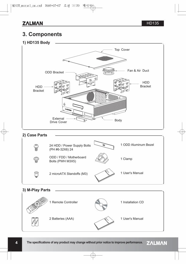
3. Components
Top Cover
ODD Bracket
BodyExternalDrive Cover
HDDBracket
HDDBracket
Fan & Air Duct
1) HD135 Body
2) Case Parts
3) M-Play Parts
24 HDD / Power Supply Bolts(PH #6-32X6) 24
ODD / FDD / MotherboardBolts (PWH M3X5)
2 microATX Standoffs (M3)
1 ODD Aluminum Bezel
1 Clamp
1 User's Manual
1 Remote Controller
2 Batteries (AAA)
1 Installation CD
1 User's Manual
ENG
LISH
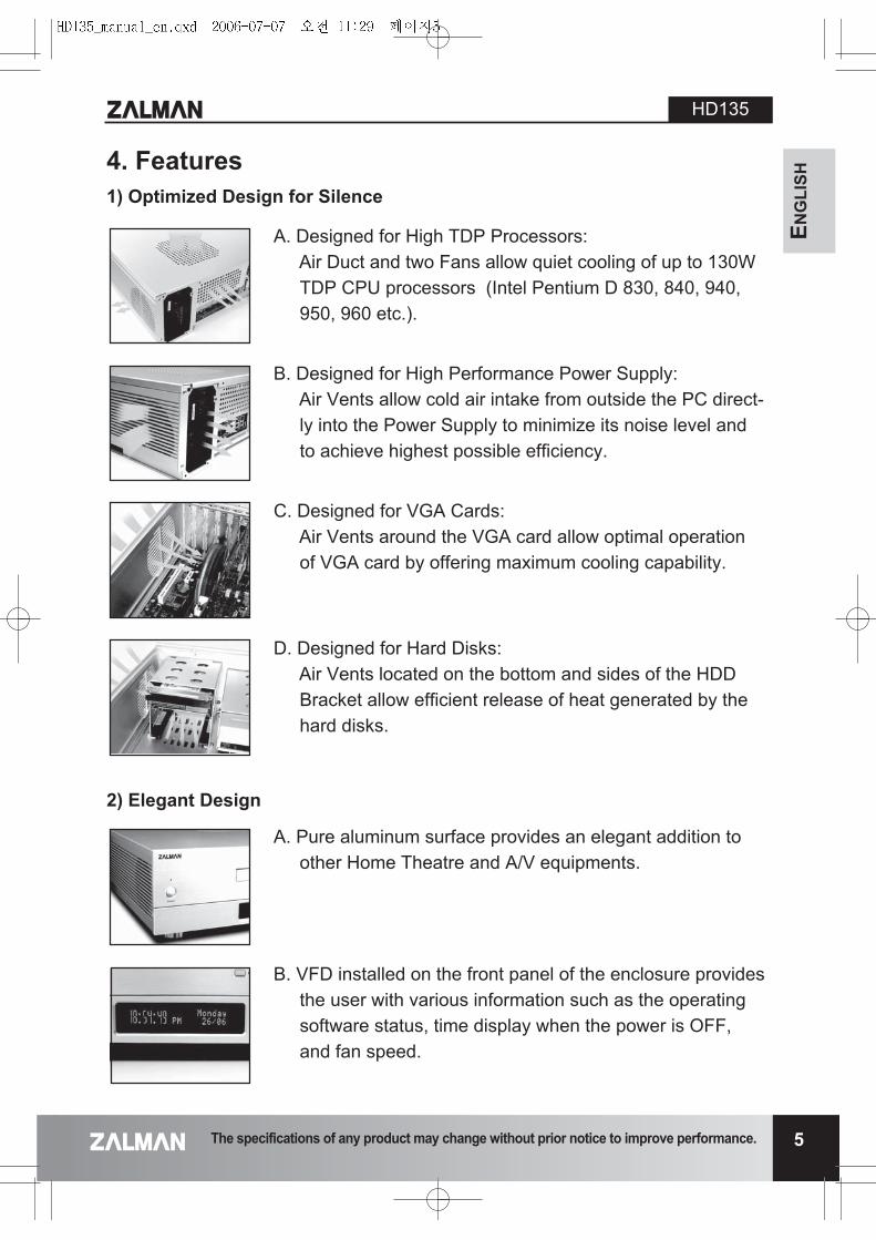
1) Optimized Design for Silence
A. Designed for High TDP Processors:Air Duct and two Fans allow quiet cooling of up to 130WTDP CPU processors (Intel Pentium D 830, 840, 940,950, 960 etc.).
B. Designed for High Performance Power Supply:Air Vents allow cold air intake from outside the PC direct-ly into the Power Supply to minimize its noise level andto achieve highest possible efficiency.
C. Designed for VGA Cards:Air Vents around the VGA card allow optimal operationof VGA card by offering maximum cooling capability.
D. Designed for Hard Disks:Air Vents located on the bottom and sides of the HDDBracket allow efficient release of heat generated by thehard disks.
A. Pure aluminum surface provides an elegant addition toother Home Theatre and A/V equipments.
B. VFD installed on the front panel of the enclosure providesthe user with various information such as the operatingsoftware status, time display when the power is OFF,and fan speed.
2) Elegant Design
4. Features
The specifications of any product may change without prior notice to improve performance.
HD135
5
HD135
6 The specifications of any product may change without prior notice to improve performance.
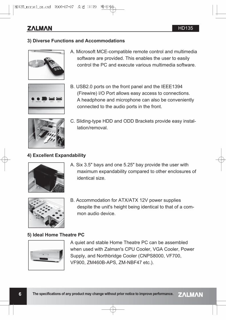
3) Diverse Functions and Accommodations
A. Microsoft MCE-compatible remote control and multimediasoftware are provided. This enables the user to easilycontrol the PC and execute various multimedia software.
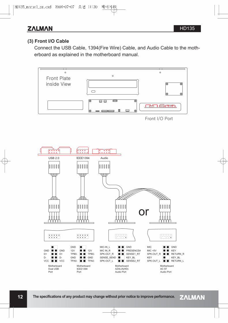
B. USB2.0 ports on the front panel and the IEEE1394(Firewire) I/O Port allows easy access to connections.A headphone and microphone can also be convenientlyconnected to the audio ports in the front.
C. Sliding-type HDD and ODD Brackets provide easy instal-lation/removal.
4) Excellent Expandability
A. Six 3.5" bays and one 5.25" bay provide the user withmaximum expandability compared to other enclosures ofidentical size.
B. Accommodation for ATX/ATX 12V power suppliesdespite the unit's height being identical to that of a com-mon audio device.
5) Ideal Home Theatre PCA quiet and stable Home Theatre PC can be assembledwhen used with Zalman's CPU Cooler, VGA Cooler, PowerSupply, and Northbridge Cooler (CNPS8000, VF700,VF900, ZM460B-APS, ZM-NBF47 etc.).
ENG
LISH
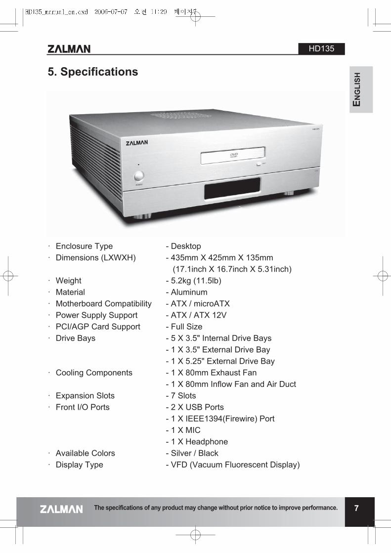
� Enclosure Type - Desktop� Dimensions (LXWXH) - 435mm X 425mm X 135mm
(17.1inch X 16.7inch X 5.31inch)� Weight - 5.2kg (11.5lb)� Material - Aluminum� Motherboard Compatibility - ATX / microATX� Power Supply Support - ATX / ATX 12V� PCI/AGP Card Support - Full Size� Drive Bays - 5 X 3.5" Internal Drive Bays
- 1 X 3.5" External Drive Bay- 1 X 5.25" External Drive Bay
� Cooling Components - 1 X 80mm Exhaust Fan- 1 X 80mm Inflow Fan and Air Duct
� Expansion Slots - 7 Slots � Front I/O Ports - 2 X USB Ports
- 1 X IEEE1394(Firewire) Port- 1 X MIC- 1 X Headphone
� Available Colors - Silver / Black� Display Type - VFD (Vacuum Fluorescent Display)
5. Specifications
The specifications of any product may change without prior notice to improve performance.
HD135
7
HD135
8 The specifications of any product may change without prior notice to improve performance.
6. Installation Guide
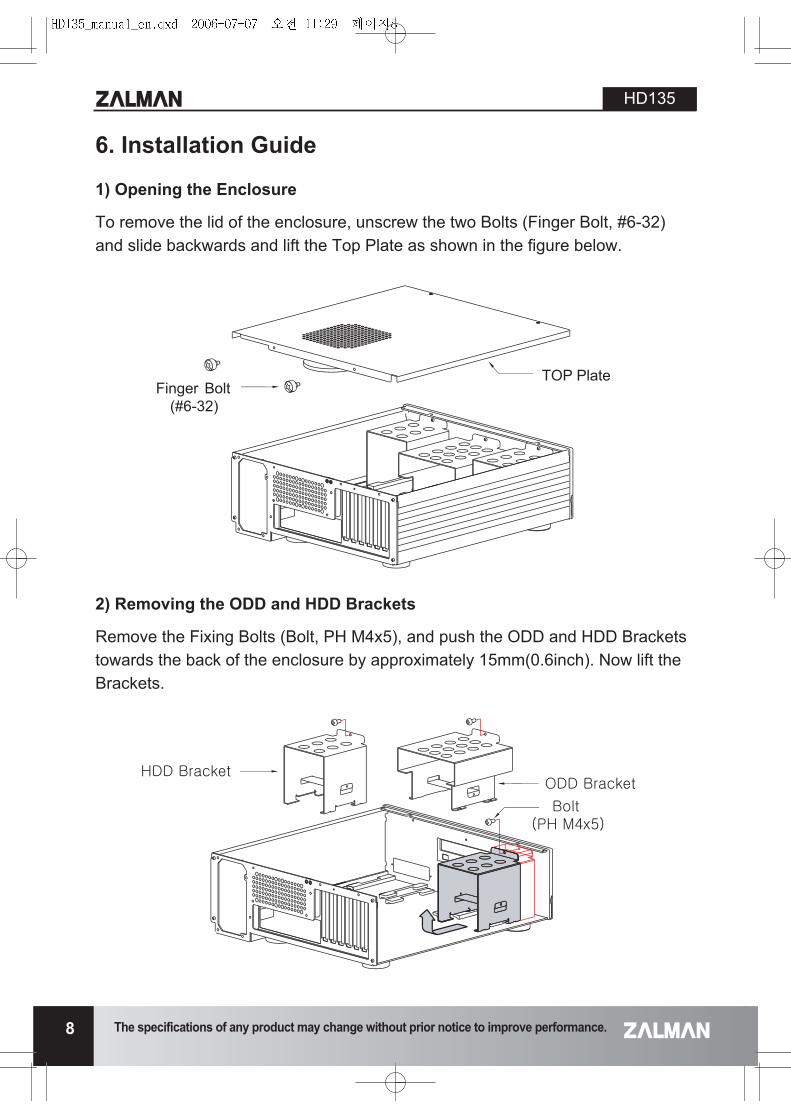
1) Opening the Enclosure
To remove the lid of the enclosure, unscrew the two Bolts (Finger Bolt, #6-32)and slide backwards and lift the Top Plate as shown in the figure below.
2) Removing the ODD and HDD Brackets
Remove the Fixing Bolts (Bolt, PH M4x5), and push the ODD and HDD Bracketstowards the back of the enclosure by approximately 15mm(0.6inch). Now lift theBrackets.
Finger Bolt(#6-32)
TOP Plate
ENG
LISH
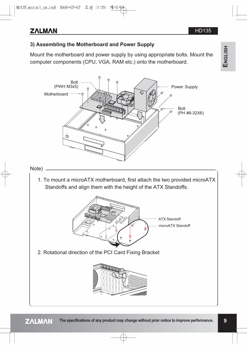
3) Assembling the Motherboard and Power Supply
Mount the motherboard and power supply by using appropriate bolts. Mount thecomputer components (CPU, VGA, RAM etc.) onto the motherboard.
The specifications of any product may change without prior notice to improve performance.
HD135
9
Bolt(PH #6-32X6)
Power SupplyBolt
(PWH M3x5)
Motherboard
1. To mount a microATX motherboard, first attach the two provided microATXStandoffs and align them with the height of the ATX Standoffs.
2. Rotational direction of the PCI Card Fixing Bracket
ATX Standoff
microATX Standoff
Note)
HD135
10 The specifications of any product may change without prior notice to improve performance.
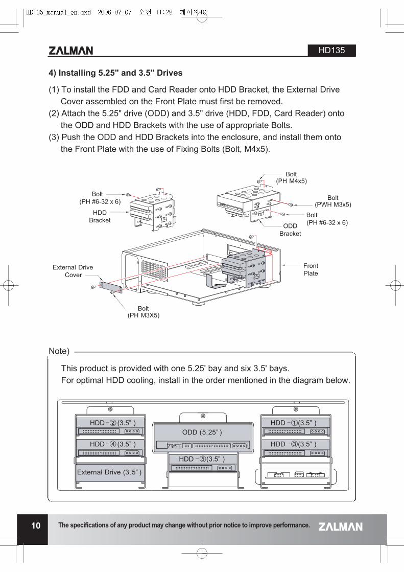
4) Installing 5.25" and 3.5" Drives
(1) To install the FDD and Card Reader onto HDD Bracket, the External DriveCover assembled on the Front Plate must first be removed.
(2) Attach the 5.25" drive (ODD) and 3.5" drive (HDD, FDD, Card Reader) ontothe ODD and HDD Brackets with the use of appropriate Bolts.
(3) Push the ODD and HDD Brackets into the enclosure, and install them ontothe Front Plate with the use of Fixing Bolts (Bolt, M4x5).
Bolt(PH #6-32 x 6)
HDDBracket
External DriveCover
Bolt(PH M3X5)
FrontPlate
ODDBracket
Bolt(PH #6-32 x 6)
Bolt(PWH M3x5)
Bolt(PH M4x5)
This product is provided with one 5.25' bay and six 3.5' bays. For optimal HDD cooling, install in the order mentioned in the diagram below.
HDD (3.5” )
HDD (3.5” )
External Drive (3.5” )
ODD (5.25” )
HDD (3.5” )
HDD (3.5” )
HDD (3.5” )
Note)
ENG
LISH
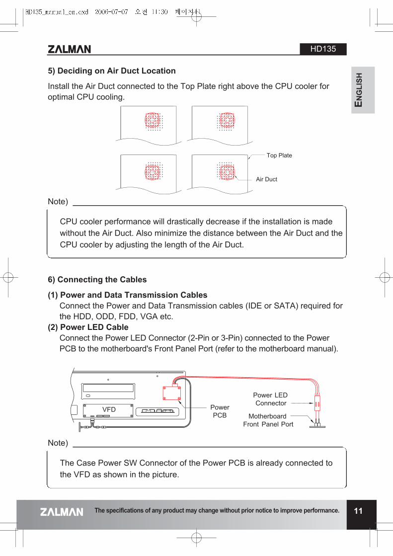
5) Deciding on Air Duct Location
Install the Air Duct connected to the Top Plate right above the CPU cooler foroptimal CPU cooling.
The specifications of any product may change without prior notice to improve performance.
HD135
11
Top Plate
Air Duct
PowerPCB
Power LEDConnector
MotherboardFront Panel Port
VFD
CPU cooler performance will drastically decrease if the installation is madewithout the Air Duct. Also minimize the distance between the Air Duct and theCPU cooler by adjusting the length of the Air Duct.
Note)
The Case Power SW Connector of the Power PCB is already connected tothe VFD as shown in the picture.
Note)
6) Connecting the Cables
(1) Power and Data Transmission CablesConnect the Power and Data Transmission cables (IDE or SATA) required forthe HDD, ODD, FDD, VGA etc.
(2) Power LED Cable Connect the Power LED Connector (2-Pin or 3-Pin) connected to the PowerPCB to the motherboard's Front Panel Port (refer to the motherboard manual).
HD135
12 The specifications of any product may change without prior notice to improve performance.
(3) Front I/O CableConnect the USB Cable, 1394(Fire Wire) Cable, and Audio Cable to the moth-erboard as explained in the motherboard manual.

ENG
LISH
(4) VFD Multi-Cable� Connect the VFD Power Connector to the Power Supply Connector. � Connect the VFD USB Connector to the motherboard's USB Port.
1. Must refer to the motherboard manual for the USB Port Pin arrangementwhen connecting the VFD USB cable. Incorrect connection can causedamage to the VFD resulting from a short circuit.
2. VFD USB Cable Colors GND : Black, +DATA : Green, -DATA : Blue, USB +5V : Red
The specifications of any product may change without prior notice to improve performance.
HD135
13
Front Plateinside View
VFD
VFD PowerConnector
Power SupplyConnector
VFD
VFD USB ConnectorMotherboard USB Port
Note)
HD135
14 The specifications of any product may change without prior notice to improve performance.
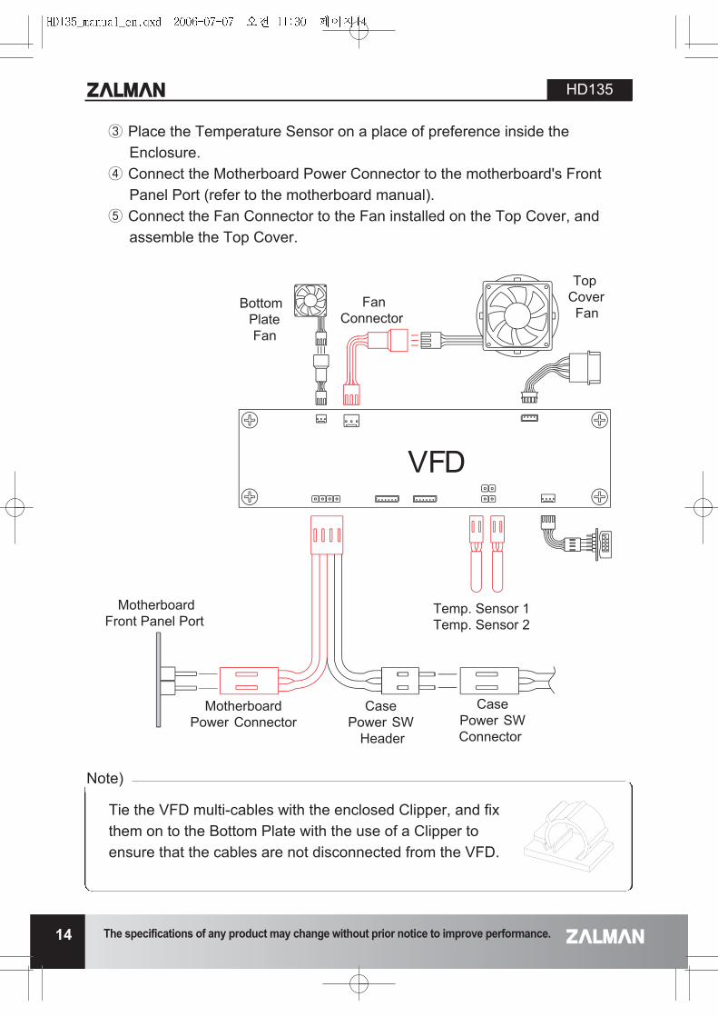
� Place the Temperature Sensor on a place of preference inside theEnclosure.
� Connect the Motherboard Power Connector to the motherboard's FrontPanel Port (refer to the motherboard manual).
Connect the Fan Connector to the Fan installed on the Top Cover, andassemble the Top Cover.
Tie the VFD multi-cables with the enclosed Clipper, and fixthem on to the Bottom Plate with the use of a Clipper toensure that the cables are not disconnected from the VFD.
TopCoverFan
BottomPlateFan
FanConnector
VFD
CasePower SW Connector
MotherboardPower Connector
CasePower SW
Header
Temp. Sensor 1Temp. Sensor 2
MotherboardFront Panel Port
Note)
ENG
LISH
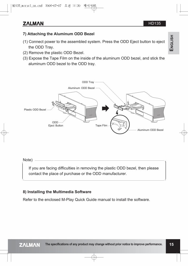
7) Attaching the Aluminum ODD Bezel
(1) Connect power to the assembled system. Press the ODD Eject button to ejectthe ODD Tray.
(2) Remove the plastic ODD Bezel. (3) Expose the Tape Film on the inside of the aluminum ODD bezel, and stick the
aluminum ODD bezel to the ODD tray.
The specifications of any product may change without prior notice to improve performance.
HD135
15
ODD Tray
Tape Film
Aluminum ODD Bezel
Plastic ODD Bezel
Aluminum ODD Bezel
ODDEject Button
8) Installing the Multimedia Software
Refer to the enclosed M-Play Quick Guide manual to install the software.
If you are facing difficulties in removing the plastic ODD bezel, then pleasecontact the place of purchase or the ODD manufacturer.
Note)
HD135
16 The specifications of any product may change without prior notice to improve performance.
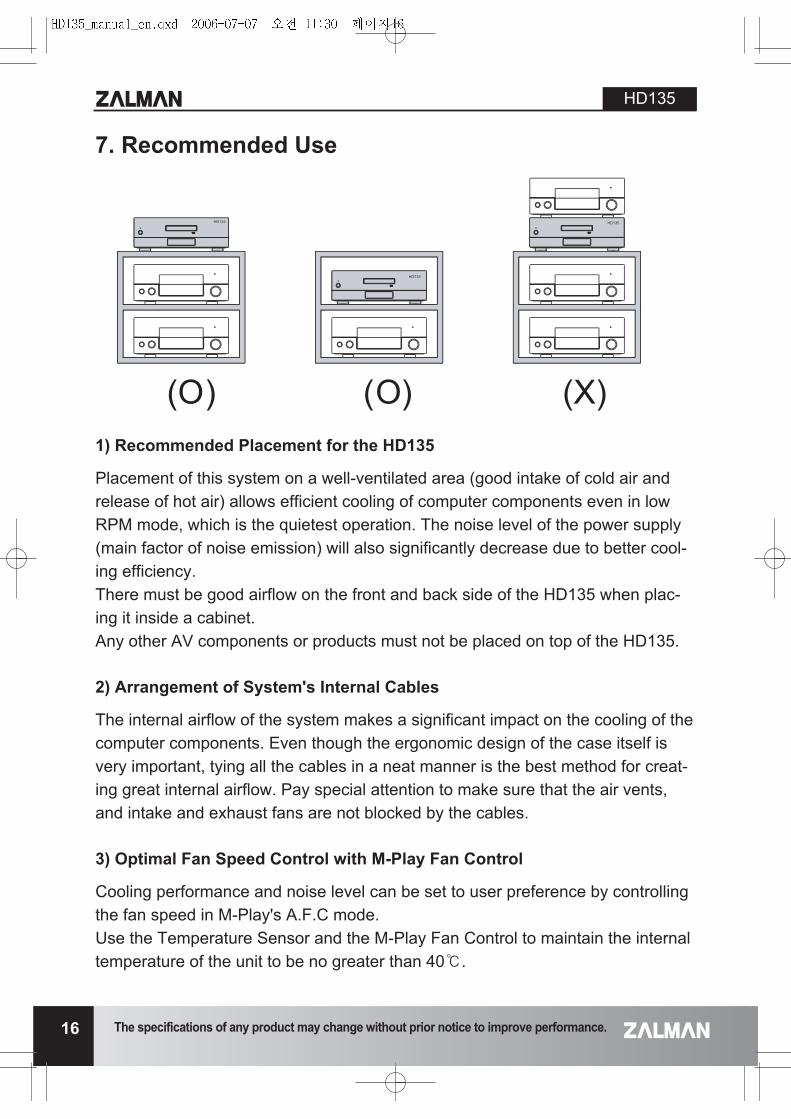
7. Recommended Use
1) Recommended Placement for the HD135
Placement of this system on a well-ventilated area (good intake of cold air andrelease of hot air) allows efficient cooling of computer components even in lowRPM mode, which is the quietest operation. The noise level of the power supply(main factor of noise emission) will also significantly decrease due to better cool-ing efficiency. There must be good airflow on the front and back side of the HD135 when plac-ing it inside a cabinet. Any other AV components or products must not be placed on top of the HD135.
2) Arrangement of System's Internal Cables
The internal airflow of the system makes a significant impact on the cooling of thecomputer components. Even though the ergonomic design of the case itself isvery important, tying all the cables in a neat manner is the best method for creat-ing great internal airflow. Pay special attention to make sure that the air vents,and intake and exhaust fans are not blocked by the cables.
3) Optimal Fan Speed Control with M-Play Fan Control
Cooling performance and noise level can be set to user preference by controllingthe fan speed in M-Play's A.F.C mode. Use the Temperature Sensor and the M-Play Fan Control to maintain the internaltemperature of the unit to be no greater than 40.
(O) (O) (X)
ENG
LISH
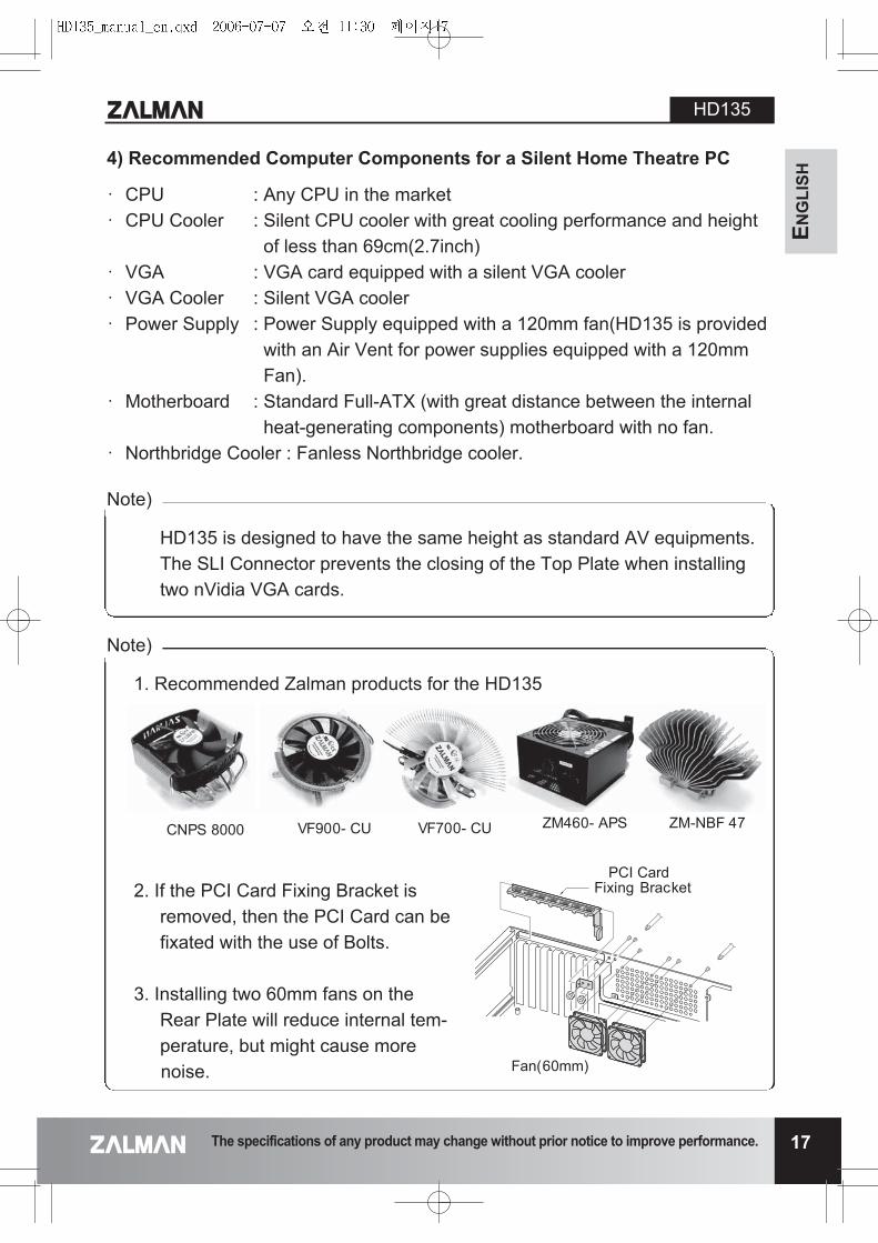
4) Recommended Computer Components for a Silent Home Theatre PC
� CPU : Any CPU in the market� CPU Cooler : Silent CPU cooler with great cooling performance and height
of less than 69cm(2.7inch)� VGA : VGA card equipped with a silent VGA cooler� VGA Cooler : Silent VGA cooler� Power Supply : Power Supply equipped with a 120mm fan(HD135 is provided
with an Air Vent for power supplies equipped with a 120mmFan).
� Motherboard : Standard Full-ATX (with great distance between the internalheat-generating components) motherboard with no fan.
� Northbridge Cooler : Fanless Northbridge cooler.
The specifications of any product may change without prior notice to improve performance.
HD135
17
HD135 is designed to have the same height as standard AV equipments.The SLI Connector prevents the closing of the Top Plate when installingtwo nVidia VGA cards.
Note)
1. Recommended Zalman products for the HD135
2. If the PCI Card Fixing Bracket isremoved, then the PCI Card can befixated with the use of Bolts.
3. Installing two 60mm fans on theRear Plate will reduce internal tem-perature, but might cause morenoise.
Note)
VF700- CUCNPS 8000 VF900- CU ZM460- APS ZM-NBF 47
PCI Card Fixing Bracket
Fan(60mm)
HD135
18 The specifications of any product may change without prior notice to improve performance.
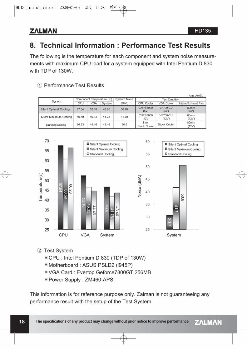
8. Technical Information : Performance Test ResultsThe following is the temperature for each component and system noise measure-ments with maximum CPU load for a system equipped with Intel Pentium D 830with TDP of 130W.
� Performance Test Results
� Test System�CPU : Intel Pentium D 830 (TDP of 130W)�Motherboard : ASUS PSLD2 (i945P)�VGA Card : Evertop Geforce7800GT 256MB�Power Supply : ZM460-APS
This information is for reference purpose only. Zalman is not guaranteeing anyperformance result with the setup of the Test System.
CPU VGA System CPU Cooler VGA Cooler Intake/Exhaust Fan
Silent Optimal Cooling 67.54 52.18 46.60 30.70 CNPS8000(5V)
VF700-CU(5V)
80mm(5V)
Silent Maximum Cooling 60.59 46.33 41.78 41.70 CNPS8000(12V)
VF700-CU(12V)
80mm(12V)
Standard Cooling 66.23 44.46 43.46 50.6Intel
Stock Cooler Stock Cooler80mm(12V)
SystemTest ConditionComponent Temperature ( ) System Noise
(dBA)
46.6
52.18
67.54
41.78
46.33
60.59
43.46
44.46
66.23
25
30
35
40
45
50
55
60
65
70
1 2 3
Silent Optimal CoolingSilent Maximum CoolingStandard Cooling
30.741.7
50.6
25
30
35
40
45
50
55
60
1
Silent Optimal CoolingSilent Maximum CoolingStandard Cooling
CPU VGA System
Noi
se (d
BA
)
System
The specifications of any product may change without prior notice to improve performance.
HD135
19
ENG
LISH
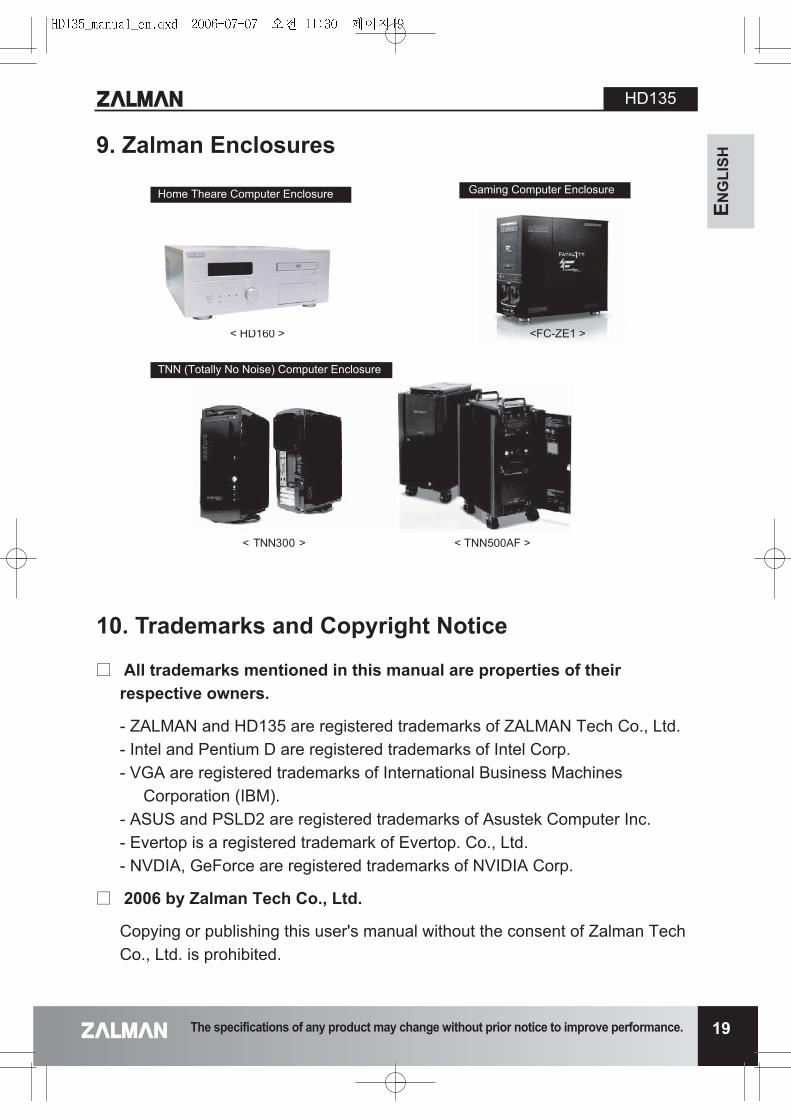
9. Zalman Enclosures
10. Trademarks and Copyright Notice
� All trademarks mentioned in this manual are properties of their respective owners.
- ZALMAN and HD135 are registered trademarks of ZALMAN Tech Co., Ltd. - Intel and Pentium D are registered trademarks of Intel Corp.- VGA are registered trademarks of International Business Machines
Corporation (IBM).- ASUS and PSLD2 are registered trademarks of Asustek Computer Inc.- Evertop is a registered trademark of Evertop. Co., Ltd.- NVDIA, GeForce are registered trademarks of NVIDIA Corp.
� 2006 by Zalman Tech Co., Ltd.
Copying or publishing this user's manual without the consent of Zalman TechCo., Ltd. is prohibited.
< HD160 > <FC-ZE1 >
TNN (Totally No Noise) Computer Enclosure
Home Theare Computer Enclosure Gaming Computer Enclosure
< TNN500AF >> 003NNT <