Embed Size (px)
Citation preview

QLD Office: 17 Oasis CourtClontarf 4019(07) 3883-0200
NSW Office: 34-36 Marigold StreetRevesby 2212(02) 9722 5555
VIC/TAS Office: 147-153 Canterbury RoadKilsyth 3137(03) 9237 7766
B&D DoorsNew Zealand: 70 Allens Road
EastTamakiAuckland, New Zealand(09) 273 8600www.bnd.co.nz
SA Office: 23 Frederick RoadRoyal Park 5014(08) 8447 4747
WA Office: 96 Mulgul RoadMalaga 6090(08) 9247 8777
INSTRUCTIONS
C-Tick approval logo min. size 3mm diam.; letters min. 3mm high N1134
with 433MHz Radio Controls
The Controll-A-Door-P hasbeen tested and complieswith the standards:AS/NZS 3350.2.95:2000(incl. Amdt1) & AS/NZSCISPR 14.1:2003
2
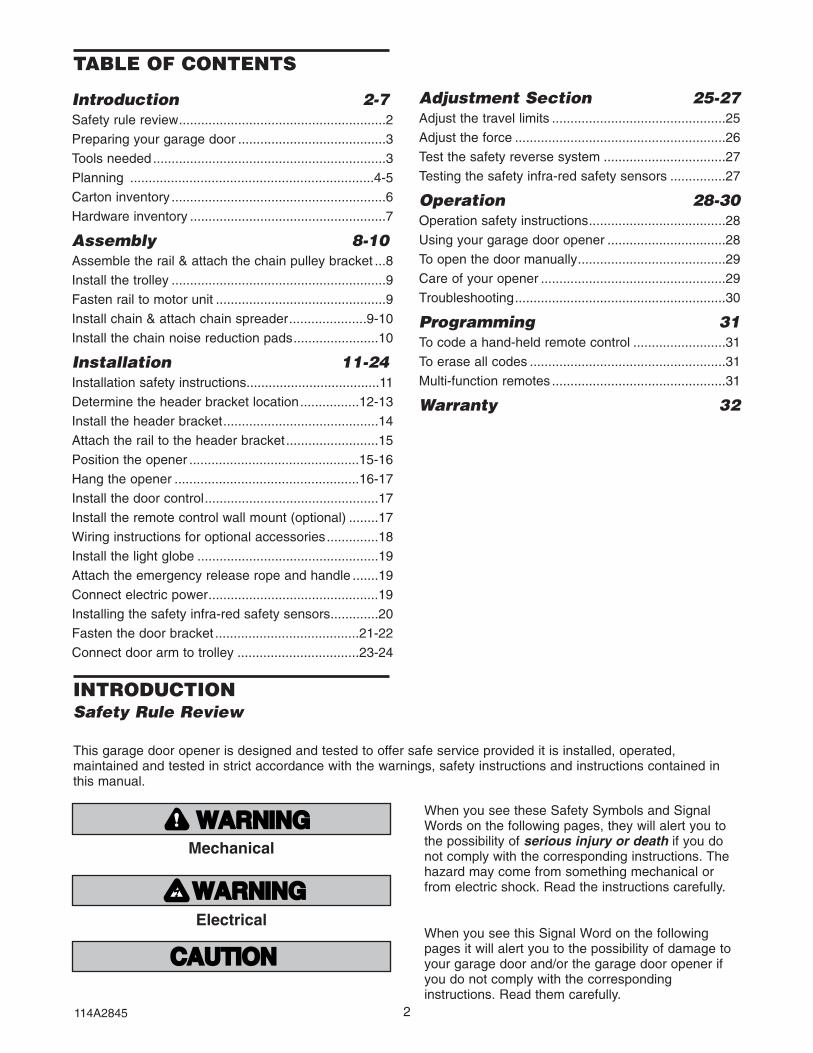
Introduction 2-7Safety rule review........................................................2
Preparing your garage door ........................................3
Tools needed...............................................................3
Planning ..................................................................4-5
Carton inventory ..........................................................6
Hardware inventory .....................................................7
Assembly 8-10Assemble the rail & attach the chain pulley bracket ...8
Install the trolley ..........................................................9
Fasten rail to motor unit ..............................................9
Install chain & attach chain spreader.....................9-10
Install the chain noise reduction pads.......................10
Installation 11-24Installation safety instructions....................................11
Determine the header bracket location................12-13
Install the header bracket..........................................14
Attach the rail to the header bracket.........................15
Position the opener ..............................................15-16
Hang the opener ..................................................16-17
Install the door control...............................................17
Install the remote control wall mount (optional) ........17
Wiring instructions for optional accessories..............18
Install the light globe .................................................19
Attach the emergency release rope and handle .......19
Connect electric power..............................................19
Installing the safety infra-red safety sensors.............20
Fasten the door bracket .......................................21-22
Connect door arm to trolley .................................23-24
Adjustment Section 25-27Adjust the travel limits ...............................................25
Adjust the force .........................................................26
Test the safety reverse system .................................27
Testing the safety infra-red safety sensors ...............27
Operation 28-30Operation safety instructions.....................................28
Using your garage door opener ................................28
To open the door manually........................................29
Care of your opener ..................................................29
Troubleshooting.........................................................30
Programming 31To code a hand-held remote control .........................31
To erase all codes .....................................................31
Multi-function remotes ...............................................31
Warranty 32
TABLE OF CONTENTS
When you see these Safety Symbols and SignalWords on the following pages, they will alert you tothe possibility of serious injury or death if you donot comply with the corresponding instructions. Thehazard may come from something mechanical orfrom electric shock. Read the instructions carefully.
When you see this Signal Word on the followingpages it will alert you to the possibility of damage toyour garage door and/or the garage door opener ifyou do not comply with the correspondinginstructions. Read them carefully.
Mechanical
INTRODUCTIONSafety Rule Review
WWARNARNINGING
CAUTIONCAUTION WWARNARNINGING
WWARNARNINGING
WWARNARNINGING
WWARNARNINGINGWWARNARNINGING
CAUTIONCAUTION WWARNARNINGING
WWARNARNINGINGElectrical
This garage door opener is designed and tested to offer safe service provided it is installed, operated,maintained and tested in strict accordance with the warnings, safety instructions and instructions contained inthis manual.
114A2845

3
Pliers
Wire Cutters
Claw Hammer
Hack Saw
Screwdriver
Adjustable End WrenchLocking pliers13mm, 11mm, and 6mm Sockets and Wrench
Drill
Tape Measure
21
Stepladder
Pencil
8mm, 5mm, and 4mm Drill Bits
Carpenter's Level
To avoid damage to the garage door and opener, disablelocks before installing and operating the opener. Use awood screw or nail to hold locks in the "open"(unlocked) position.Operation at other than 230V/50 Hz will cause openermalfunction and damage.
To prevent possible SERIOUS INJURY OR DEATH:• Always call for professional B&D garage door service if
garage door binds, sticks, or is out of balance. Anunbalanced garage door might not reverse whenrequired.
• NEVER try to loosen, move, or adjust garage door,door springs, cables, pulleys, brackets or theirhardware, all of which are under EXTREME tension.
• Disable ALL locks and remove all ropes connected togarage door before installing and operating garagedoor opener to avoid entanglement.
• This unit should not be installed in a damp or wet space.• The door must not extend over public byway during
operation.• This product is provided with a power supply cord of
special design which, if damaged, must be replaced bya power supply cord of the same type; such a powersupply cord may be obtained from you local B&Ddistributor and must be fitted by a specialist.
• This unit is supplied as a plug-in-device and it isstrongly advised that this unit remain a plug-in device.Any alterations or changes to this will result in theopener warranty being void.
Preparing your garage door
• Disable locks. Insert wood screws or nails to keepthem unlocked.
• Remove any ropes connected to garage door.
TESTING YOUR DOOR
Before you begin, complete the following test tomake sure your door is balanced and is not stickingor binding:
• Lift the door about halfway as shown. Release thedoor. It should stay in place, supported entirely byits springs.
• Raise and lower the door to see if there is anybinding or sticking.
If your door binds, sticks, or is out of balance, call forprofessional garage door service.
Tools needed
During assembly, installation and adjustment of theopener, instructions will call for hand tools asillustrated.
ONE-PIECE DOORSECTIONAL DOOR
PORTE ARTICULÉE PORTE RIGIDE
ONE-PIECE DOORSECTIONAL DOOR
PORTE ARTICULÉE PORTE RIGIDE
Sectional Door
One-Piece Door
WWARNARNINGING
CAUTIONCAUTION
WWARNARNINGING
CAUTIONCAUTION
114A2845

Safety Reversing Sensor
Horizontal and vertical reinforcementis needed for lightweight garage doors(fibreglass, steel, aluminum, door with glass panels, etc.).See page 21 for details.
Support bracket & fastening hardwareis required.See page 17.
— —
— —
— —
— —
Door Centre
Header Wall
SafetyReversingSensor
Gap between floor and bottom of door must not exceed 6mm.
FINISHED CEILING
Extension Spring
Torsion Spring Access Door
OR
HeaderSleeve Bracket
HeaderBracket
Trolley
EmergencyGarage
CLOSED POSITION
Rail Assembly
Motor Unit
10o
Must be attached below Panel Re-enforcement if used.
Centre Stile optimum location for attachment
4
PlanningIdentify the type and height of your garage door.Survey your garage area to see if any of theconditions below apply to your installation. Additionalmaterials may be required. You may find it helpful torefer back to this page and the accompanyingillustrations as you proceed with the installation ofyour opener.Depending on your requirements, there are severalinstallation steps which may call for materials and/orhardware not included in the carton.• Installation Step 1 – Look at the wall or ceiling
above the garage door. The header bracket mustbe securely fastened to structural supports.
• Installation Step 5 – Do you have a finished ceilingin your garage? If so, a support bracket andadditional fastening hardware may be required.
B&D recommends the use of safety infraredreversing sensors on all installations ofautomatic garage door openers.• Installation Step 10:
– Depending upon garage construction, extensionbrackets or wood blocks may be needed toinstall the infrared safety sensors.
– Alternate floor mounting of the infrared safetysensors will require hardware not provided.
• Do you have an access door in addition to thegarage door? If not, Model T7012 EmergencyAccess Device is required.
SECTIONAL DOOR INSTALLATIONS• Do you have a steel, aluminum, fibreglass or glass
panel door? If so, horizontal and vertical reinforce-ment is required (Installation Step 11).
• The opener is normally installed at the centre ofthe door. If there is a torsion spring or centrebearing plate in the way of the header bracket ordoor bracket area, the opener may be installedwithin 300mm to the left or right of the door centre.See Installation Steps 1 and 11.
• Look at the garage door where it meets the floor. Itmust close on the floor all the way across.Otherwise, the safety reverse system may not workproperly. See Adjustment Step 3. Floor or doorshould be repaired.
OPENER ARM MOUNTING LOCATIONMust be mounted on a stile. Add an additional stile ifrequired or offset mount the opener (see below andpage 5). Attach arm 1/3 panel height from top at 10O
as shown.
Sectional Door Installation
114A2845
Excess MUST be removed
Re-enforcement
Pan
el H
eigh
t10o
1/3
Safety Reversing Sensor
Horizontal and vertical reinforcementis needed for lightweight garage doors(fiberglass, steel, aluminum, door with glass panels, etc.).See page 21 for details.
Support bracket & fastening hardwareis required.See page 17.
— —
— —
— —
— —
Door Center
Header Wall
SafetyReversingSensor
Gap between floor and bottom of door must not exceed 6mm.
FINISHED CEILING
Extension Spring
Torsion Spring Access Door
OR
HeaderSleeve Bracket
HeaderBracket
Trolley
StraightDoorArm
EmergencyReleaseRope & Handle
Door BracketGarage
Door
CurvedDoorArm
GarageDoorSpring
HeaderWall
CLOSED POSITION
Rail Assembly
Motor Unit
Excess MUST be removed
Re-enforcement
Pan
el H
eigh
t
10o
1/3

5
AccessDoor
Gap between floor and bottom of door must not exceed 6mm.Safety
Reversing Sensor
The Chamberlain Group, Inc.One-Piece Door with Track Installation (Cable -USA)3/3/93
HeaderBracket
Header Sleeve Bracket
DoorBracket
StraightDoorArm
CurvedDoor Arm
Trolley
EmergencyReleaseRope & Handle
Rail
GarageDoor
HeaderWall
SafetyReversing Sensor
CLOSED POSITION
Safety Reversing Sensor
FINISHED CEILINGSupport bracket & fasteninghardware is required. See page 17.
Safety Reversing Sensor
Gap between floor and bottomof door must not exceed 6mm.
HeaderWall
Access Door
HeaderSleeve Bracket
HeaderBracket
Door Bracket
HeaderWall
GarageDoor
One-Piece Door without Track
Safety Reversing Sensor
FINISHED CEILINGSupport bracket& fasteninghardware is required.See page 17.
Safety Reversing Sensor
Gap between floor and bottomof door must not exceed 6mm.
HeaderWall
Access Door
CLOSED POSITION
HeaderSleeve Bracket
HeaderBracket
Trolley
StraightDoorArm
EmergencyReleaseRope & Handle
Door Bracket
CurvedDoorArmHeader
Wall
Rail
GarageDoor
Chain
One-Piece Door with Track
AccessDoor
Gap between floor and bottom of door must not exceed 6mm.Safety
Reversing Sensor
The Chamberlain Group, Inc.One-Piece Door with Track Installation (Cable -USA)3/3/93
HeaderBracket
Header Sleeve Bracket
DoorBracket
StraightDoorArm
CurvedDoor Arm
Trolley
EmergencyReleaseRope & Handle
Rail
GarageDoor
HeaderWall
SafetyReversing Sensor
CLOSED POSITION
114A2845
OFF CENTRE INSTALLATION OF OPENERIn situations where obstruction prevent mounting theopener centrally, offsetting the opener attachment ispossible within the following range - 1/4 Door widthfrom centre.NOTE: Even though it is acceptable practise to offcentre mount the opener, the further off centre theopener is mounted the more dependent is the dooroperation on a good installation. This relates tocorrect set-up of opener and track, and correct doorbalance.
The installation of the IR Safety Sensor isrecommended for an off centre mount application.
ONE-PIECE DOOR INSTALLATIONS• Generally, a one-piece door does not require
reinforcement. If your door is lightweight, you canrefer to the information relating to sectional doorsin Installation Step 11.
• Depending on your door’s construction, you mayneed additional mounting hardware for the door
bracket (Step 11).• The gap between the bottom of the garage door
and the floor cannot exceed 6mm. Otherwise, thesafety reverse system may not work properly. SeeAdjustment Step 3. The floor or the door should berepaired.
11//44 DDoooorr WWiiddtthh
1/4 DDoooorr WWiiddtthh

6
Your garage door opener is packaged in two cartonswhich contains the motor unit and the parts illustratedbelow. If anything is missing, carefully check thepacking material. Parts may be stuck in the foam.
Hardware for assembly and installation is shown onthe next page. Save the carton and packing materialuntil installation and adjustment is complete.
Carton Inventory
Straight DoorArm Section
Curved DoorArm Section
Safety LabelsandLiterature
Chain
Hanging Brackets
1-Function RemoteControl Transmitter (1)
Remote ControlTransmitter Visor Clip
Light Lens (1)
RailCentreSection
Chain Spreader with Screws and Washers
3-Function Mini RemoteControl Transmitter (1)
TrolleyInner Trolley
4-Piece Rail
1-Piece Rail
Door Bracket
Rail Straps
Header Bracket
Header Sleeve BracketBell Wire
IlluminatedPush Button
Light globe
Remote ControlWall Mount Bracket
Vibration Isolators
Chain Noise Reduction Pads
114A2845

Hardware Inventory
Separate all hardware and group as shown below for the assembly and installation procedures.
7
Spring /Trolley Nut (1) MasterLink (2)
ASSEMBLY
INSTALLATION
NOTICE
Handle
RopeLock Washer8mm (7)
Hex Screw8mm x 20mm (4)
Nut8mm (7)
Carriage Bolt8mm x 65mm (2)
Screw (2)Washered Screw 25mm (4)(mounted in opener)
Anchors8mm x 40mm (6)
InsulatedStaples
Rail Grease
Dry Wall Anchors (2)
Screw6AB x 25mm (2)
Carriage bolt (1)
Stop Bolt (1)
Ring Fastener (4)
Sheet Metal Screw8mm x 13mm (2)
Lag Screw8mm x 45mm (2)
Lag Screw8mm x 40mm (4)
Clevis Pin8mm x 32mm (1)
Clevis Pin8mm x 13mm (2)
Clevis Pin8mm x 25mm (2)
114A2845

8
ASSEMBLY STEP 1Assemble the RailNOTE: If your opener came with a one piece rail,proceed to Assembly step 2, page 9.Grease inside edges of rail brace sections. Place railpieces on flat surface for assembly. All four railsections are interchangeable. Slide rail braces ontorail section. Connect rail by sliding rail brace ontonext rail section. Tap rail assembly on piece of wooduntil rail sections are flush. Repeat with remainingrail sections.
Install the ChainRemove chain from carton and lay chain out on floor(do not allow chain to twist). Push pins of master linkbar through chain link and hole in back end of trolley.Push cap over pins and onto notches. Slide clip-onspring over cap and onto pin notches until both pinsare securely locked in place.
Insert Chain into Rail & AssembleHeader SleeveSlide pulley bracket and inner trolley into back(opener end) of rail assembly, be sure to insert pulleybracket as shown with arrow pointing toward front(header end) of rail. Push bracket toward front(header end) of rail. Insert carriage bolt throughheader sleeve bracket. Loosely thread spring nutonto carriage bolt. Insert carriage bolt of headersleeve assembly into bold cut out in pulley bracket.Slide header sleeve assembly on to front (headerend) of rail.
Spring Trolley Nut
Carriage Bolt
HARDWARE SHOWN ACTUAL SIZE
Rail Piece
Rail Brace
Rail assembly
Piece of Wood
Rail Piece
Grease
PulleyBracket
Carriage BoltHeader Sleeve Bracket
Front (Header End) of Rail
Back(Opener End) of Rail Assembly
Pulley Bracket
Inner Trolley
Arrow
RAIL ASSEMBLY
Spring
Cap
Back End of Trolley
Master Link Bar
Chain Link
INSTALLING THE CHAIN
Spring Nut
Header SleeveBracket
Carriage Bolt
114A2845

9
ASSEMBLY STEP 3Attach Chain Spreader
Attach chain spreader to opener with phillips panhead screws. Chain Spreader
Phillips Pan Head Screws
Opener
To avoid serious damage to opener, ONLY use screwsmounted in top of motor unit.
WWARNARNINGING
CAUTIONCAUTION
ATTENTIONATTENTION
AVERTISSEMENTAVERTISSEMENT
ASSEMBLY STEP 2Attach Trolley to RailSlide outer trolley into rail assembly, be sure arrowon trolley is heading in direction of door is heading indirection of door. Slide outer trolley down rail until itengages with inner trolley.
114A2845
Outer Trolley
Arrow
Arrow
Rail Assembly
Towards Door
ASSEMBLY STEP 4Fasten Rail to Opener & Install ChainRemove four washered bolts from top of opener. Placerail on opener, flush with stops on top of opener. Wrapchain around slot in spreader and over sprocket. Pushidler pulley bracket assembly toward front of the rail toeliminate excess slack in chain. Align bolt holes onbrackets with bolt holes on opener. Secure brackets toopener with previously removed bolts . Tighten boltssecurely. The opener sprocket teeth must engagethe chain. Insert bolt into trolley stop bolt hole securewith lock washer and nut.CAUTION: Use only those bolts mounted in thetop of opener. Use of any other bolts will causeserious damage to opener.
Set Chain TensionThread spring nut on carriage bolt unit finger tight.Insert a screwdriver tip into one of the slots of the nutring and brace it firmly against the header sleeve.Place an open end wrench on the square end of thespring nut, slightly rotate nut about 1/4 turn clockwiseuntil nut ring is released against header sleeve. Thissets spring to optimum chain tension. chain may slipoff sprocket if chain is too loose. If chain does slip re-tighten spring nut by turing nut clockwise 1/2 turn.Do NOT overtighten chain.
To avoid possible SERIOUS INJURY to fingers frommoving garage door opener:• ALWAYS keep hand clear of sprocket while operating
opener.• Securely attach chain spreader before operating.
WWARNARNINGING
CAUTIONCAUTION WWARNARNINGING
WWARNARNINGING

Bolt
Trolley Stop Bolt Hole
LockWasher Nut
Bolt NutLock Washer
Washered Bolt
Sprocket
2
Stops
4
SprocketSpreader
StopsSpreader
Screwdriver Tip
Nut Ring
Wrench
Spring Nut
Header Sleeve
Screwdriver Tip
Nut Ring
Wrench
Spring Nut
Header Sleeve
FASTEN RAIL TO OPENERSET CHAIN TENSION
10114A2845
114mm
114mm
1. Clean and remove grease fromrail in areas where pads will beinstalled.
2. With chain tensioned, lift up thechain and place noise reductionpads under the chain in orientationshown.
3. Install with adhesive side downallowing pad to stick to rail.
ASSEMBLY STEP 5Install Chain Noise Reduction Pads(optional)
HARDWARE SHOWN ACTUAL SIZE
Spring /Trolley Nut
Nut Ring
Trolley
25mmBEFORE
SquareEnd Nut Ring
32mmAFTER RELEASE
TrolleySquareEnd

11
IMPORTANT INSTALLATION INSTRUCTIONS
1. READ AND FOLLOW ALL INSTALLATIONWARNINGS AND INSTRUCTIONS.
2. Install garage door opener only on properlybalanced and lubricated garage door. Animproperly balanced door may not reverse whenrequired and could result in severe injury ordeath.
3. All repairs to cables, spring assemblies and otherhardware MUST be made by a trained doorsystems technician before installing opener.
4. Disable all locks and remove all ropes connectedto garage door before installing opener to avoidentanglement.
5. Install garage door opener 2.1m or more abovefloor.
6. Mount emergency release handle 1.8m feet abovefloor.
7. NEVER connect garage door opener to powersource until instructed to do so.
8. NEVER wear watches, rings or loose clothingwhile installing or servicing opener. They couldbe caught in garage door or openermechanisms.
9. Install wall-mounted garage door control:• within sight of the garage door • out of reach of children at minimum height
of 1.5m• away from all moving parts of the door.
10. Place entrapment warning label on wall next togarage door control.
11. Place manual release/safety reverse test label inplain view on inside of garage door.
12. Upon completion of installation, test safetyreversal system. Door MUST reverse on contactwith a 40mm high object on the floor.
To reduce the risk of severe injury or death:
NNINGING
IONION WWARNARNINGING
WWARNARNINGING
INSTALLATION
114A2845

12
INSTALLATION STEP 1Determine the Header BracketLocation
Installation procedures vary according to garage doortypes. Follow the instructions which apply to yourdoor.
SECTIONAL DOORAND ONE-PIECE DOOR WITH TRACK1. Close the door and mark the inside vertical
centreline of the garage door.
2. Extend the line onto the header wall above thedoor.
NOTE: You can fasten the header bracket within300mm of the left or right of the door center only if atorsion spring or centre bearing plate is in the way; oryou can attach it to the ceiling (see page 14) whenclearance is minimal. (It may be mounted on the wallupside down if necessary, to gain approximately12mm.)
If you need to install the header bracket on a 40mmreinforcement board (on wall or ceiling), use lagscrews (not provided) to securely fasten the 40mmreinforcement board to structural supports as shownhere and on page 13. If installing into masonry, useconcrete anchors.
3. Open your door to the highest point of travel asshown. Draw an intersecting horizontal line on theheader wall 50mm above the high point. Thisheight will provide travel clearance for the top edgeof the door.
Proceed to Step 2, page 14.
One-piecedoor withhorizontal
track
Header Wall
Ceiling
Sectional door with curved track One-piece door with horizontal track
Track
Highest Pointof Travel
Door
Door
Track50mm Header Wall
Highest Pointof Travel
50mm
Sectional doorwith curvedtrack
Header Wall
Ceiling
Sectional door with curved track One-piece door with horizontal track
Track
Highest Pointof Travel
Door
Door
Track
SECTIONAL DOOR AND ONE-PIECE DOOR WITH TRACK
50mm Header Wall
Highest Pointof Travel
50mm
VerticalCentreline
FinishedCeiling
VerticalCentreline
HeaderWall
40mmReinforcement Board Structural
Supports
To prevent possible SERIOUS INJURY or DEATH:• Header bracket MUST be RIGIDLY fastened to
structural support on header wall or ceiling, otherwisegarage door might not reverse when required. DO NOTinstall header bracket over drywall.
• Concrete anchors MUST be used if mounting headerbracket or 40mm reinforcement board into masonry.
• NEVER try to loosen, move or adjust garage door,springs, cables, pulleys, brackets, or their hardware, allof which are under EXTREME tension.
• ALWAYS call a trained door systems technician ifgarage door binds, sticks, or is out of balance. Anunbalanced garage door might not reverse whenrequired.
WWARNARNINGING
CAUTIONCAUTION WWARNARNINGING
WWARNARNINGING
114A2845

13
One Piece Door Without Track1/30/92 - 4/7/92
HeaderWall Vertical
Centreline
VerticalCentrelineof GarageDoor
40mmReinforcementBoard
UnfinishedCeiling
OPTIONALCEILING MOUNT
FOR HEADER BRACKET
StructuralSupports
40mmReinforcementBoard
ONE-PIECE DOOR WITHOUT TRACK1. Close the door and mark the inside vertical
centreline of your garage door. Extend the lineonto the header wall above door, as shown.
If headroom clearance is minimal, you can installthe header bracket on the ceiling. See page 14.
If you need to install the header bracket on a40mm reinforcement board (on wall or ceiling), uselag screws (not provided) to securely fasten the40mm reinforcement board to structural supportsas shown. If installing into masonry, use concreteanchors (not provided).
2. Open your door to the highest point of travel asshown. Measure the distance from the top of thedoor to the floor. Subtract the actual height of thedoor. Add 200mm to the remainder.(See Example).
3. Close the door and draw an intersecting horizontalline on the header wall at the determined height.
If the total number of millimeters exceeds theheight available in your garage, use themaximum height possible, or refer to page 14for ceiling installation.
Door
Highest Pointof Travel
Header Wall
Pivot
Dis
tanc
e
Header Wall
Highest Pointof Travel
Door
Floor Floor
Dis
tanc
e
JambHardware
The Chamberlain Group, Inc.Position Header BracketDoors Without Track1/30/92 - 4/7/92
One-piece door without track: pivot hardware
Door
Highest Pointof Travel
Header Wall
Pivot
Dis
tanc
e
Header Wall
Highest Pointof Travel
Door
Floor
Dis
tanc
e
JambHardware
The Chamberlain Group, Inc.Position Header BracketDoors Without Track1/30/92 - 4/7/92
One-piece door without track: jamb hardware
EXAMPLEDistance from top of door (at highest point of travel) to floor ................ 2300mm
Actual height of door.................................... -2100mm
Remainder.................................................... 200mm
Add............................................................... +200mm
Bracket height on header wall ..................... =400mm
(Measure UP from top of CLOSED door.)
Proceed to Step 2, page 14.
114A2845

14
INSTALLATION STEP 2Install the Header Bracket
WALL HEADER BRACKET INSTALLATION• Centre the bracket on the vertical guideline with the
bottom edge of the bracket on the horizontal line(with the arrow pointing toward the ceiling).
• Mark all of the bracket holes. Drill 4.5mm (3/16")pilot holes and fasten the bracket with woodscrews. For concrete mount, use concrete anchorsprovided.
Lag Screw 8mm x 40mm
Anchors 8mm x 40mm
HARDWARE SHOWN ACTUAL SIZE
Lag Screws8mm x 40mm
Highest Point of Garage Door Travel
VerticalCenter Line
HeaderWall
GarageDoor
UP
CEILING MOUNT ONLY
Wall Mounting Holes
Optional Wall Mounting Holes
The nail hole is for positioning only. You must use lag screws to mount the header bracket.
UPCEILING MOUNT ONLY
Door Spring
HeaderBracket25mm
Board
VerticalCenter Line
Bracket Holes
Bracket Holes
50mm(2")
25mm Board
HeaderWall
VerticalCentre Line
Lag Screws8mm x 40mmHeader
Bracket
Highest Point of Garage Door Travel
VerticalCentre Line
GarageDoor
UP
CEILING MOUNT ONLY
Ceiling Mounting Holes
The nail hole is for positioning only.You must use lag screws to mount the header bracket.
UP
Lag Screws8mm x 40mm
Garage Door
Vertical Centreline
Header Wall
– Finished Ceiling –
HeaderBracket
15cm Maximum
VerticalCentreline
DoorSpring
Bracket Holes
Bracket Holes
150mm
(6")
DoorSpring
Header Wall
Lag Screws8mm x 40mm
HeaderBracket
Vertical Centreline
– Finished Ceiling –
CEILING HEADER BRACKET INSTALLATION• Extend vertical guideline onto the ceiling.
• Centre the bracket on the vertical mark no morethan 150mm (6") from the wall. Make sure thearrow is pointing toward the wall.
• Mark all of the bracket holes (5). Drill 4.5mm (3/16")pilot holes and fasten the bracket with woodscrews. For concrete ceiling mount, use concreteanchors provided.
114A2845

15
Ring fastener (2)
Temporary Support
Garage Door
Header WallHeader Bracket
Header Sleeve
Bracket
Clevis PIn8mm x 13mm (2)
Ring FastenerRing Fastener
Clevis Pin8mm x 13mm
Clevis Pin8mm x 13mm
Header SleeveBracket
Rail
HARDWARE SHOWN ACTUAL SIZE
INSTALLATION STEP 3Attach the Rail to the Header Bracket
• Position opener on garage floor below the header bracket. Use packing material to protect the cover. Raiserail until holes in the header sleeve and holes in the header bracket align. Join with clevis pins. Insert ringfasteners to secure.NOTE: To enable the rail to clear sectional door springs, it may be necessary to lift opener onto a temporarysupport. The opener must either be secured to a support or held firmly in place by another person.
114A2845
INSTALLATION STEP 4Position the Opener
Follow instructions which apply to your door type as illustrated.
SECTIONAL DOOR OR ONE-PIECE DOOR WITH TRACK
A 25 mm board laid flat is convenient for setting an ideal door-to-rail distance.
• Raise the opener onto a stepladder. You will need help at this point if the ladder is not tall enough.
• Open the door all the way and place a 25mm board laid flat on the top section beneath the rail.
• If the top section or panel hits the trolley when you raise the door, pull down on the trolley release armto disconnect inner and outer sections. Slide the outer trolley toward the motor unit. The trolley can remaindisconnected until Installation Step 12 is completed.
To prevent damage to garage door, rest garage dooropener rail on 25mm board or equivalent placed on topsection of door.
WWARNARNINGING
CAUTIONCAUTION
Trolley Release Arm
ENGAGED RELEASED

16
Top of Motor Unit
HeaderBracket
Top of door
Door
ONE-PIECE DOOR WITHOUT TRACK• With the door fully open and parallel to the floor,
measure the distance from the floor to the top ofthe door.
• Using a stepladder as a support, raise the top ofthe opener to this height.
• The top of the door should be level with the top ofthe motor unit. Do not position the opener morethan 50mm above this point.
25mmBoard laid flat
Top of Motor Unit
Rail
Door
HeaderBracket
Top of door
25mm�Board laid flat
Rail
Door
114A2845
INSTALLATION STEP 5Hang the OpenerThe opener must be securely fastened to astructural support of the garage.Two representative installations are shown. Yours maybe different. Hanging brackets should be angled(Figure 1) to provide rigid support. On finished ceilings,(Figure 2) attach a sturdy metal bracket (not supplied)to a structural support before installing the opener. 1. On each side of opener measure the distance from
the opener to the structural support (or ceiling).2. Cut both pieces of the hanging bracket to required
lengths. Flatten one end of each bracket and bendor twist to fit the fastening angles. Do not bend atthe bracket holes. Drill 4.5mm (3/16") pilot holes inthe structural supports (or ceiling). Attach flattenedends of brackets to supports with wood screws.
3. Lift opener and fasten to hanging brackets withscrew, lock washer and nut. Check to make surerail is centered over the door.
4. Remove 25mm (1") board. Operate door manually.If door hits the rail, raise header bracket.
5. Use rail grease and lubricate inside surface of rail.
Hex Screw8mm x 20mm Nut 8mm Lock Washer 8mm
Lag Screw8mm x 45mm
HARDWARE SHOWN ACTUAL SIZE
To avoid possible SERIOUS INJURY from a fallinggarage door opener, fasten it SECURELY to structuralsupports of the garage. Concrete anchors MUST be usedif installing any brackets into masonry.
WWARNARNINGING
CAUTIONCAUTION
MeasureDistance
StructuralSupports
Lock Washer 8mmScrew 8mmNut 8mm
1
Lag Screws�8mm x 45mm
Bracket(Not provided)
FINISHED CEILING
Lock Washer 8mm Screw 8mmNut 8mm
HiddenSupport
Lag Screws8mm x 45mm
Figure 1
MeasureDistance
StructuralSupports
Lock Washer 8mmScrew 8mmNut 8mm
1
Lag Screws�8mm x 45mm
Bracket(Not provided)
FINISHED CEILING
Lock Washer 8mm Screw 8mmNut 8mm
HiddenSupport
Lag Screws8mm x 45mm
Figure 2

17114A2845
INSTALLATION STEP 6Install the door controlLocate the door control within sight of the door at aminimum height of 1.5m where small childrencannot reach, and away from all moving parts ofthe door and door hardware.1. Strip 6mm of insulation from one end of the bell
wire. Connect it to the two screw terminals on theback of the door control by color: white wire to 2and white/red wire to 1.
2. Fasten the Lighted Door Control Button securelywith 6ABx1-1/2” screws. If installing into drywall,drill 4mm holes and use the anchors provided.
3. Run the bell wire up the wall and across theceiling to the opener. Use insulated staples tosecure the wire in several places. Do not piercewire with a staple, creating a short or open circuit.
4. Receiver terminals are located on the back panelof the opener.
5. Strip 11mm of insulation from the end of the bellwire and insert in wire trap: white to 2 andwhite/red to 1.
6. Permanently attach the entrapment warning labelto the wall near the door control, and the manualrelease/safety reverse test in a prominent locationon the inside of the garage door.
Bell Wire
The Chamberlain Group, Inc.Figure 17 - Wall Control4210E3/6/92
WHT-2
RED-1
Lighted DoorControl Button
Terminal Screws
Lighted DoorControl Button
Bell Wire
Screw 6ABx1-1/2”Lighted Door Control Button Drywall Anchors
Insulated Staples
Remote Control Wall Mount (optional)1. Locate wall mount bracket at least 1.5m above the
floor.2. Attach to the wall with 2 x ø 3.5 max flat head
screws (not provided).3. Slide remote control onto wall mount bracket.NOTE: Tightening the wall mount screws will reduceclearance between bracket and wall.
HARDWARE SHOWN ACTUAL SIZE

18
WIRING INSTRUCTIONS FORACCESSORIES
• Place entrapment warning label on the inside ofdoor as a reminder of safe operating procedures.Place the manual release/safety reverse testlabel in plain view on the inside of the garagedoor.
To prevent possible SERIOUS INJURY or DEATH fromelectrocution:• Be sure power is not connected BEFORE installing door
control.To prevent possible SERIOUS INJURY or DEATH from aclosing garage door:• Install door control within sight of garage door, out of
reach of children at a minimum height of 1.5m, andaway from all moving parts of door.
• NEVER permit children to operate or play with doorcontrol push buttons or remote control transmitters.
• Activate door ONLY when it can be seen clearly, isproperly adjusted, and there are no obstructions to doortravel.
• ALWAYS keep garage door in sight until completelyclosed. NEVER permit anyone to cross path of closinggarage door.
WARNING
CAUTION
WWARNARNINGING
WARNINGWARNING
ATTENTION
AVERTISSEMENT AVERTISSEMENTAVERTISSEMENT
AVERTISSEMENTAVERTISSEMENTKEY SWITCH MODEL 059009To opener terminal: white to 2; white/red to 1.
SAFETY INFRARED REVERSING SENSORMODEL 062153To opener terminal screws: white to 2; Black to 3.
DOOR CONTROL PANEL 062159To opener terminal: white to 2; white/red to 1.
INSTALLATION STEP 7Install the Light
• Press the release tabs on both sides of lens.Gently rotate lens back and downward until thelens hinge is in the fully open position. Do notremove the lens. Install a 40 watt maximum (socketsize E27), light globe in the socket as shown.
• The light will turn on and remain lit for 2-1/2minutes when power is connected. After 2-1/2minutes it will turn off.
• Reverse the procedure to close the lens.
Replace burned out globes with rough servicelight globes.
Release tabs of lens
40W MaxLight Globe
Socket
114A2845

19114A2845
Overhand Knot
Emergency Release Handle
Trolley Release Arm
NOTICE
The Chamberlain Group, Inc.Figure 16 - Manual Release4210E - 3/8/93
Rope
Trolley
• To prevent possible SERIOUS INJURY or DEATH froma falling garage door:– If possible, use emergency release handle to
disengage trolley ONLY when garage door isCLOSED. Weak or broken springs or unbalanceddoor could result in an open door falling rapidlyand/or unexpectedly.
– NEVER use emergency release handle unless garagedoorway is clear of persons and obstructions.
• NEVER use handle to pull door open or closed. If ropeknot becomes untied, you could fall.
WWARNARNINGING
CAUTIONCAUTION WARNING
WARNINGINSTALLATION STEP 8Attach the Emergency ReleaseRope and Handle
• Thread one end of the rope through the hole in thetop of the red handle so "NOTICE" reads right sideup as shown. Secure with an overhand knot atleast 25mm from the end of the rope to preventslipping.
• Thread the other end of the rope through the holein the release arm of the outer trolley.
• Adjust rope length so the handle is 1.8m abovethe floor. Secure with an overhand knot.
If it is necessary to cut the rope, heat seal the cutend with a match or lighter to prevent unraveling.
INSTALLATION STEP 9Connect Electric Power
To avoid installation difficulties, do not run the openerat this time.
Connect the operator to a mains which is properlyearthed according to the wiring instruction tagattached to the power supply cord (and as specifiedby local code).
To prevent possible SERIOUS INJURY or DEATH fromelectrocution or fire:• Be sure power is not connected to the opener, and
disconnect power to circuit BEFORE removing cover toestablish permanent wiring connection.
• Garage door installation and wiring MUST be incompliance with all local electrical and building codes.
• NEVER use an extension cord, 2-wire adapter, orchange plug in any way to make it fit outlet. Be surethe opener is earthed.
WWARNARNINGING
CAUTIONCAUTION WWARNARNINGING
WWARNARNINGING

20
Invisible Light Beam Protection Area
The Chamberlain Group, Inc. Safety Sensor Instruction Sheet Page 1 Protector System Disk #1 (Yellow) 11/5/91 - 1/15/92
Wing Nut
Sensor Beam 100-150mm max. above floor
Sensor Beam 100-150mm max. above floor
Facing the door from inside the garage
INSTALLATION STEP 10Install the Safety InfraredReversing Sensors (Optional)It is recommended that safety infrared reversingsensors be connected and aligned correctly tothe garage door opener.
The force, as measured on the closing edge ofthe door, should not exceed 400N (40kg). If theclosing force is adjusted to more than 400N, thissafety system must be installed.
IMPORTANT INFORMATION ABOUT THE SAFETY REVERSING SENSORSWhen properly connected and aligned, the safetyinfrared reversing sensors will detect an obstacle inthe path of its electronic beam. The sending eyetransmits an invisible light beam to the receiving eye.If an obstruction breaks the light beam while the dooris closing, the door will stop and reverse to full openposition, and the opener light will flash 10 times.
The units must be installed inside the garage so thatthe sending and receiving eyes face each otheracross the door, between 100-150mm above thefloor. Either can be installed on the left or right of thedoor as long as the sun never shines directly into thereceiving eye lens.
The brackets must be securely fastened to a solidsurface such as the wall framing. If installing inmasonry construction, add a piece of wood at eachlocation to avoid drilling extra holes in masonry ifrepositioning is necessary.
The invisible light beam path must be unobstructed.No part of the garage door (or door tracks, springs,hinges, rollers or other hardware) may interrupt thebeam while the door is closing.
114A2845
Note: This operator, when used with safety reversingsensor 062153, meets product standardrequirements for a monitored sensor system.
If the operator detects that the safety sensors nolonger function properly, the operator will not closeuntil the sensor continuity has been returned.

21
Carriage Bolt 8mm x 65mm
Nut 8mmLock Washer 8mm
Sheet Metal Screw
HARDWARE SHOWN ACTUAL SIZE
114A2845
Fibreglass, aluminum or lightweight steel garage doorsWILL REQUIRE reinforcement BEFORE installation ofdoor bracket. To prevent damage to garage doorsreinforce inside of door with angle iron both verticallyand horizontally.
WWARNARNINGING
CAUTIONCAUTIONINSTALLATION STEP 11Fasten the Door Bracket
Follow instructions which apply to your door type asillustrated below or on the following page.
A horizontal reinforcement brace should be longenough to be secured to two or three verticalsupports. A vertical reinforcement brace shouldcover the height of the top panel.Figure 1 shows one piece of angle iron as thehorizontal brace. For the vertical brace, two pieces ofangle iron are used to create a U-shaped support.The best solution is to check with your garage doormanufacturer for an opener installation doorreinforcement kit.
NOTE: Many door reinforcement kits provide fordirect attachment of the clevis pin and door arm. Inthis case you will not need the door bracket; proceedto Step 12.
SECTIONAL DOORS1. Centre the door bracket on the previously marked
vertical centreline used for the header bracketinstallation. Note correct UP placement, asstamped inside the bracket.
2. Position the top edge of the bracket 50mm -100mm (2"-4") below the top edge of the door, ORdirectly below any structural support across the topof the door.
3. Mark, drill holes and install as follows, dependingon your door’s construction:
Metal or light weight doors using a vertical angleiron brace between the door panel support andthe door bracket: • Drill 4.5mm (3/16") fastening holes. Secure the
door bracket using the two 8mm x 13mm (1/4"-14x5/8") self-threading screws. (Figure 2A)
• Alternately, use two 8mm (5/16") bolts, lockwashers and nuts. (Figure 2B)
Metal, insulated or light weight factory reinforceddoors: • Drill 4.5mm (3/16") fastening holes. Secure the
door bracket using the self-threading screws.(Figure 3)
Wood Doors:• Use top and bottom or side to side door bracket
holes. Drill 8mm (5/16") holes through the doorand secure bracket with 8mm x 65mm (5/16"x2")carriage bolts, lockwashers and nuts (notprovided). (Figure 4)
NOTE: The 8mm x 13mm(1/4"-14x5/8") self-threadingscrews are not intended foruse on wood doors.
DoorBracket
VerticalCentreline of Garage Door
UP
VerticalReinforcement
DoorBracket
Nut8mm
Bolt8mm x 65mm
Lock Washer8mm
UP
VerticalReinforcement
Self-ThreadingScrew8mm x 13mm
VerticalCentreline of Garage Door
Self-ThreadingScrew8mm x 13mm
Self-Threading Screw1/4"-14x5/8"
DoorBracket
VerticalCentreline of Garage Door
UP
VerticalReinforcement
DoorBracket
Nut8mm
Bolt8mm x 65mm
Lock Washer8mm
UP
VerticalReinforcement
Self-ThreadingScrew8mm x 13mm
VerticalCentreline of Garage Door
UPUP
Inside Edgeof Door orReinforcement Board
Bolt8mm x 65mm
Self-ThreadingScrew8mm x 13mm
VerticalCentreline of Garage Door
VerticalCentreline of Garage Door
UPUP
Inside Edgeof Door orReinforcement Board
Bolt8mm x 65mm
Self-ThreadingScrew8mm x 13mm
VerticalCentreline of Garage Door
VerticalCentreline of Garage Door
Figure 1
Figure 2A
Figure 4
Figure 2B
HARDWARESHOWNACTUAL SIZE
Figure 3

22
Carriage Bolt 8mm x 65mm
Nut 8mmLock Washer 8mm
Sheet Metal Screw
HARDWARE SHOWN ACTUAL SIZE
114A2845
Header Wall
VerticalCentreline ofGarage Door
Finished Ceiling
OptionalPlacementof DoorBracket
HeaderBracket
DoorBracket
2x4 Support
For a door with no exposed framing,or for the optional installation, use lag screws 5/16"x1-1/2" (Not Provided)to fasten door bracket.
METAL DOOR
Top of Door(Inside Garage)
DoorBracket
OptionalPlacement
Top Edgeof Door
Self-Threading Screw 1/4"-14x5/8"
DoorBracket
Top of Door(Inside Garage)
Carriage Bolt5/16"x2"(Not Provided)
OptionalPlacement
Lock Washer5/16"
Nut5/16"-18
Top Edgeof Door
WOOD DOOR
HORIZONTAL AND VERTICAL REINFORCEMENT IS NEEDED FOR LIGHTWEIGHT GARAGE DOORS (FIBREGLASS, ALUMINUM, STEEL, DOORS WITH GLASS PANEL, ETC.). (NOT PROVIDED)
ONE-PIECE DOORS Please read and comply with the warnings andreinforcement instructions on the previous page.They apply to one-piece doors also.
• Centre the door bracket on the top of the door, inline with the header bracket as shown. Mark eitherthe left and right, or the top and bottom holes.
• Metal Doors: Drill 4.5mm (3/16") pilot holes andfasten the bracket with the 8 x 13mm (1/4"-14x5/8") self-threading screws provided.
• Wood Doors: Drill 8mm (5/16") holes and use8mm x 2" (5/16"x2") carriage bolts, lock washersand nuts or 8 x 40mm (5/16"x1-1/2") lag screwsdepending on your installation needs.
NOTE: The door bracket may be installed on the topedge of the door if required for your installation.(Refer to the dotted line optional placement drawing.)

23
INSTALLATION STEP 12Connect Door Arm to Trolley
Follow instructions which apply to your door type asillustrated below and on the following page.
SECTIONAL DOORS ONLY• Make sure garage door is fully closed. Pull the
emergency release handle to disconnect the outertrolley from the inner trolley. Slide the outer trolleyback (away from the door) about 200mm as shownin Figures 1, 2 and 3.
Figure 1:• Fasten straight door arm section to outer trolley
with the 8mm x 25mm clevis pin. Secure theconnection with a ring fastener.
• Fasten curved section to the door bracket in thesame way, using the 8mmx 32mm clevis pin.
Figure 2:• Bring arm sections together. Find two pairs of
holes that line up and join sections. If possible, usethe top and bottom holes on the curved door arm,as shown.
Figure 3, Hole Alignment Alternative:• If holes in curved arm are above holes in straight
arm, disconnect straight arm. Cut about 150mmfrom the solid end. Reconnect to trolley with cutend down as shown.
• Bring arm sections together.
• Find two pairs of holes that line up and join withscrews, lock washers and nuts.
• Pull the emergency release handle toward theopener at a 45° angle so that the trolley releasearm is horizontal. Proceed to Adjustment Step 1,page 25. Trolley will re-engage automatically whenopener is operated.
Ring Fastener
DoorBracket
Clevis Pin8mm x 32mm
CurvedDoor Arm
StraightDoor Arm
Clevis Pin8mm x 25mm
Inner Trolley
Outer Trolley
LockWashers8mm
Nuts8mm
Door Bracket
Hex Screws8mm x 20mm
EmergencyReleaseHandle
LockWashers8mm
Nuts8mm
Hex Screws8mm x 20mm
Cut This End
Figure 1
Figure 2
Figure 3
Lock Washer 8mmNut 8mm Ring Fastener
Hex Screw8mm x 20mm
Clevis Pin8mm x 25mm (Trolley)
Clevis Pin8mm x 32mm (Door Bracket)
HARDWARE SHOWN ACTUAL SIZE
114A2845
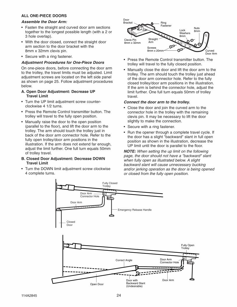
ALL ONE-PIECE DOORS
Assemble the Door Arm:• Fasten the straight and curved door arm sections
together to the longest possible length (with a 2 or3 hole overlap).
• With the door closed, connect the straight doorarm section to the door bracket with the8mm x 32mm clevis pin.
• Secure with a ring fastener.
Adjustment Procedures for One-Piece DoorsOn one-piece doors, before connecting the door armto the trolley, the travel limits must be adjusted. Limitadjustment screws are located on the left side panelas shown on page 25. Follow adjustment proceduresbelow.
A. Open Door Adjustment: Decrease UPTravel Limit
• Turn the UP limit adjustment screw counter-clockwise 4 1/2 turns.
• Press the Remote Control transmitter button. Thetrolley will travel to the fully open position.
• Manually raise the door to the open position(parallel to the floor), and lift the door arm to thetrolley. The arm should touch the trolley just inback of the door arm connector hole. Refer to thefully open trolley/door arm positions in theillustration. If the arm does not extend far enough,adjust the limit further. One full turn equals 50mmof trolley travel.
B. Closed Door Adjustment: Decrease DOWNTravel Limit
• Turn the DOWN limit adjustment screw clockwise4 complete turns.
24
Nuts8mmLock
Washers8mm
RingFastener
StraightArm
Screws8mm x 20mm
DoorBracket
Clevis Pin8mm x 32mm
CurvedDoor Arm
Door Arm
Door ArmConnector Hole
ClosedDoor
Fully ClosedTrolley
Emergency Release Handle
Fully OpenTrolley
Open DoorDoor withBackward Slant(Undesirable)
Door ArmConnector Hole
Door Arm
Correct Angle
Nuts8mmLock
Washers8mm
RingFastener
StraightArm
Screws8mm x 20mm
DoorBracket
Clevis Pin8mm x 25mm
CurvedDoor Arm
Door Arm
Door ArmConnector Hole
ClosedDoor
Fully ClosedTrolley
Emergency Release Handle
Fully OpenTrolley
Open DoorDoor withBackward Slant(Undesirable)
Door ArmConnector Hole
Door Arm
Correct Angle
• Press the Remote Control transmitter button. Thetrolley will travel to the fully closed position.
• Manually close the door and lift the door arm to thetrolley. The arm should touch the trolley just aheadof the door arm connector hole. Refer to the fullyclosed trolley/door arm positions in the illustration.If the arm is behind the connector hole, adjust thelimit further. One full turn equals 50mm of trolleytravel.
Connect the door arm to the trolley.• Close the door and join the curved arm to the
connector hole in the trolley with the remainingclevis pin. It may be necessary to lift the doorslightly to make the connection.
• Secure with a ring fastener.
• Run the opener through a complete travel cycle. Ifthe door has a slight "backward" slant in full openposition as shown in the illustration, decrease theUP limit until the door is parallel to the floor.
NOTE: When setting the up limit on the followingpage, the door should not have a "backward" slantwhen fully open as illustrated below. A slightbackward slant will cause unnecessary buckingand/or jerking operation as the door is being openedor closed from the fully open position.
114A2845
25
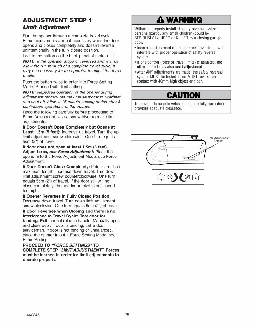
ADJUSTMENT STEP 1Limit Adjustment
Run the opener through a complete travel cycle.Force adjustments are not necessary when the dooropens and closes completely and doesn't reverseunintentionally in the fully closed position.Locate the button on the back panel of motor unit.NOTE: if the operator stops or reverses and will notallow the run through of a complete travel cycle, itmay be necessary for the operator to adjust the forceprofile.
Push the button twice to enter into Force SettingMode. Proceed with limit setting.NOTE: Repeated operation of the opener duringadjustment procedures may cause motor to overheatand shut off. Allow a 15 minute cooling period after 5continuous operations of the opener.Read the following carefully before proceeding toForce Adjustment. Use a screwdriver to make limitadjustments.If Door Doesn't Open Completely but Opens atLeast 1.5m (5 feet): Increase up travel. Turn the uplimit adjustment screw clockwise. One turn equals5cm (2") of travel.If door does not open at least 1.5m (5 feet).Adjust force, see Force Adjustment: Place theopener into the Force Adjustment Mode, see ForceAdjustment.If Door Doesn't Close Completely: If door arm is atmaximum length, increase down travel. Turn downlimit adjustment screw counterclockwise. One turnequals 5cm (2") of travel. If the door still will notclose completely, the header bracket is positionedtoo high.If Opener Reverses in Fully Closed Position:Decrease down travel. Turn down limit adjustmentscrew clockwise. One turn equals 5cm (2") of travel.If Door Reverses when Closing and there is noInterference to Travel Cycle: Test door forbinding. Pull manual release handle. Manually openand close door. If door is binding, call a doorserviceman. If door is not binding or unbalanced,place the opener into the Force Setting Mode, seeForce Settings. PROCEED TO “FORCE SETTINGS” TOCOMPLETE STEP “LIMIT ADJUSTMENT”. Forcesmust be learned in order for limit adjustments tooperate properly.
Limit Adjustment �Screws
Without a properly installed safety reversal system,persons (particularly small children) could beSERIOUSLY INJURED or KILLED by a closing garagedoor.• Incorrect adjustment of garage door travel limits will
interfere with proper operation of safety reversalsystem.
• If one control (force or travel limits) is adjusted, theother control may also need adjustment.
• After ANY adjustments are made, the safety reversalsystem MUST be tested. Door MUST reverse oncontact with 40mm high object on floor.
WWARNARNINGING
CAUTIONCAUTION
To prevent damage to vehicles, be sure fully open doorprovides adequate clearance.
WWARNARNINGING
CAUTIONCAUTION
114A2845

ADJUSTMENT STEP 2Adjust the Force
The force, as measured on the closing edge ofthe door, should not exceed 400N (40kg). If theclosing force is measured to more than 400N, aSafety Infrared Reversing Sensor must beinstalled See step 3 on page 27.The force setting button is located on the back panelof the motor unit. The force setting regulates theamount of power required to open and close thedoor. If the forces are too light, door travel may beinterrupted by nuisance reversals.
Locate the button on the back panel of motor unit.Push the button twice to enter into Force SettingMode. The LED (Indicator Light) will flash. Push thewall control or the programmed remote control thatwas shipped with your opener. The door will travel toeither the OPEN or CLOSE position. Push the buttonagain, the door will travel to the opposite position.Push the button again if the LED is stilling blinking.
The door must travel through a complete cycle UPand DOWN in order for the force to be set properly. Ifthe unit reverses before it reaches the Open or CloseLimit repeat the process. The LED (indicator light) willstop flashing when the force has been learned.
Note: If unable to set limits return to page 25.
26
Adjust Force - SEARS
Button
ButtonPress 2 times
Without a properly installed safety reversal system,persons (particularly small children) could beSERIOUSLY INJURED or KILLED by a closing garagedoor.• Too much force on garage door will interfere with
proper operation of safety reversal system.• NEVER increase force beyond minimum amount
required to close garage door. • NEVER use force adjustments to compensate for a
binding or sticking garage door.• If one control (force or travel limits) is adjusted, the
other control may also need adjustment.• After ANY adjustments are made, the safety reversal
system MUST be tested. Door MUST reverse oncontact with 40mm high object on floor.
• The force, as measured on the closing edge ot thedoor, should not exceed 400N (40kg). If the closingforce is more than 400N, a Safety Infrared ReversingSensor must be installed. Do not use the force settingprocedure to compensate for a binding or stickinggarage door. Excessive force will interfere with theproper operation of the Safety Reverse System ordamage the garage door.
WWARNARNINGING
CAUTIONCAUTION
114A2845

ADJUSTMENT STEP 3Test the Safety Reverse System
TEST• With the door fully open, place a 40mm board on
the floor, centered under the garage door.• Operate the door in the down direction. The door
must reverse on striking the obstruction.
ADJUST• If the door stops on the obstruction, it is not
traveling far enough in the down direction.Increase the DOWN limit by turning the DOWNlimit adjustment screw counterclockwise 1/4 turn.NOTE: On a sectional door, make sure limitadjustments do not force the door arm beyond astraight up and down position. See the illustrationon page 23.
• Repeat the test.• When the door reverses on the 40mm board,
remove the obstruction and run the opener through3 or 4 complete travel cycles to test adjustment.
If the door will not reverse on the board afterrepeated adjustment attempts, call for professionalB&D garage door service.
IMPORTANT SAFETY CHECK:Repeat Adjustment Steps 1, 2 and 4 after:• Each adjustment of door arm length, limits, or
force controls.• Any repair to or adjustment of the garage door
(including springs and hardware).• Any repair to or buckling of the garage floor.• Any repair to or adjustment of the opener.
ADJUSTMENT STEP 4Test the Safety Infrared ReversingSensors (if installed)• Press the remote control push button to open the
door.
• Place the opener carton in the path of the door.
• Press the remote control push button to close thedoor. The door will not move more than 25mm,and the door control will blink 10 times.
The garage door opener will not close from a remoteif the indicator light in either sensor is off (alertingyou to the fact that the sensor is misaligned orobstructed).
If the opener closes the door when the safetyreversing sensor is obstructed (and the sensorsare no more than 150mm above the floor), call forprofessional B&D garage door service.
The Chamberlain Group, Inc. Safety Sensor Instruction Sheet Page 1 Protector System Disk #1 (Yellow) 11/5/91 - 1/15/92
Safety Reversing Sensor Safety Reversing Sensor
Step 3 Test Safety Reverse System SEARS 315-699 (Yellow Disk #2)Models 53315, 53415, 535156, 53625 & 53699
6/20/89 - 6/27/89
GARAGE DOOR
40mm board laid flat
Without a properly installed safety reversal system,persons (particularly small children) could beSERIOUSLY INJURED or KILLED by a closing garagedoor. • Safety reversal system MUST be tested every month.• If one control (force or travel limits) is adjusted, the
other control may also need adjustment.• After ANY adjustments are made, the safety reversal
system MUST be tested. Door MUST reverse oncontact with 40mm high object on the floor.
Without a properly installed safety reversing sensor,persons (particularly small children) could be SERIOUSLYINJURED or KILLED by a closing garage door. The force, as measured on the closing edge ot the door,should not exceed 400N (40kg). If the closing force ismore than 400N, the Safety Infrared Reversing Sensormust be installed. Do not use the force setting procedureto compensate for a binding or sticking garage door.Excessive force will interfere with the proper operation ofthe Safety Reverse System or damage the garage door.
WWARNARNINGING
CAUTIONCAUTION
WWARNARNINGING
CAUTIONCAUTION
27114A2845

28
Using Your Garage Door Opener
Your opener will operate with up to twelve remotecontrol transmitters, one entry keypad, and one dip-switch code transmitter. If you purchase a newremote, or if you wish to deactivate any remote,follow the instructions in the Programming section.
Activate your opener with any of the following:• The hand-held Remote Control: Hold the large
push button down until the door starts to move.• The wall-mounted Door Control: Hold the push
button down until the door starts to move.• The Keyless Entry (Optional): Must be
programmed before use.
When the opener is activated:1. If open, the door will close. If closed, it will open.2. If closing, the door will stop and reverse.3. If opening, the door will stop.
4. If the door has been stopped in a partially openposition, it will close.
5. If obstructed while closing, the door will reverse. Ifthe obstruction interrupts the sensor beam, theopener lights will blink for five seconds.
6. If obstructed while opening, the door will stop.
7. If fully open and the Infrared Safety ReversingSensor is installed, the door will not close whenthe beam is broken. The sensor has no effect inthe opening cycle.
The opener light will turn on under the followingconditions: when the opener is initially plugged in;when power is restored after interruption; when theopener is activated.
It will turn off automatically after 2-1/2 minutes. Globepower is 40 watts maximum.
IMPORTANT SAFETY INSTRUCTIONS
1. READ AND FOLLOW ALL WARNINGS ANDINSTRUCTIONS.
2. ALWAYS keep remote controls out of reach of children.NEVER permit children to operate or play with garagedoor control push buttons or remote controls.
3. ONLY activate garage door when it can be seen clearly, itis properly adjusted, and there are no obstructions todoor travel.
4. ALWAYS keep garage door in sight until completelyclosed. NO ONE SHOULD CROSS THE PATH OF THEMOVING DOOR.
5. If possible, use emergency release handle to disengagetrolley ONLY when garage door is CLOSED. Weak orbroken springs or unbalanced door could result in anopen door falling rapidly and/or unexpectedly.
6. NEVER use emergency release handle unless garagedoorway is clear of persons and obstructions.
7. NEVER use handle to pull garage door open or closed. Ifrope knot becomes untied, you could fall.
8. If one control (force or travel limits) is adjusted, theother control may also need adjustment.
9. After ANY adjustments are made, the safety reversalsystem MUST be tested.
10. Safety reversal system MUST be tested every month.Garage door MUST reverse on contact with 40mm highobject on the floor.
11. ALWAYS KEEP GARAGE DOOR PROPERLY BALANCED(see page 3). An improperly balanced door may notreverse when required and could result in severe injuryor death.
12. All repairs to cables, spring assemblies and otherhardware, all of which are under EXTREME tension,MUST be made by a trained door systems technician.
13. ALWAYS disconnect electric power to garage dooropener before making any repairs or removing covers.
14. The force, as measured on the closing edge ot the door,should not exceed 400N (40kg). If the closing force ismore than 400N, a Safety Infrared Reversing Sensormust be installed. Do not use the force settingprocedure to compensate for a binding or stickinggarage door. Excessive force will interfere with theproper operation of the Safety Reverse System ordamage the garage door.
15. SAVE THESE INSTRUCTIONS.
To reduce the risk of severe injury or death:
NNINGING
IONTION WWARNARNINGING
WWARNARNINGINGOPERATION
114A2845

29
To Open the Door Manually
DISCONNECT THE TROLLEY:The door should be fullyclosed if possible. Pull downon the emergency releasehandle (so that the trolleyrelease arm snaps into avertical position) and lift thedoor manually. The lockoutfeature prevents the trolleyfrom reconnectingautomatically, and the doorcan be raised and loweredmanually as often asnecessary.
TO RE-CONNECT THE TROLLEY: Pull the emergency releasehandle toward the opener ata 45° degree angle so thatthe trolley release arm ishorizontal. The trolley willreconnect on the next UP orDOWN operation, eithermanually or by using thedoor control or remote.
Lockout position(Manual disconnect)
TrolleyRelease ArmEmergency
Release Handle(Pull Down)
NOTICE
TrolleyRelease Arm
EmergencyRelease Handle(Pull Down & BackTowards Opener) NOTICE
NOTICE
NOTICE
TrolleyRelease Arm
EmergencyRelease Handle(Pull Down & BackTowards Opener)
TrolleyRelease ArmEmergency �
Release Handle �(Pull Down)
To reconnect
TrolleyRelease ArmEmergency
Release Handle(Pull Down)
NOTICE
TrolleyRelease Arm
EmergencyRelease Handle(Pull Down & BackTowards Opener) NOTICE
NOTICE
NOTICE
TrolleyRelease Arm
EmergencyRelease Handle(Pull Down & BackTowards Opener)
TrolleyRelease ArmEmergency �
Release Handle �(Pull Down)
Care of Your Opener
LIMIT AND FORCE ADJUSTMENTS:Weather conditions maycause some minor changes indoor operation requiring somere-adjustments, particularlyduring the first year ofoperation.
Pages 25 and 26 refer to thelimit and force adjustments.Repeat the safety reverse test (AdjustmentStep 3, page 27) after any adjustment of limits orforce.
MAINTENANCE SCHEDULE
Once a Month• Manually operate door. If it is unbalanced or
binding, call for professional garage door service.
• Check to be sure door opens & closes fully. Adjustlimits and/or force if necessary. (See pages 25and 26.)
• Repeat the safety reverse test. Make anynecessary adjustments. (See Adjustment Step 3.)
Twice a Year• Check chain tension. Disconnect trolley first. Adjust
if necessary (see page 11).
Once a Year• Oil door rollers, bearings and hinges. The opener
does not require additional lubrication. Do notgrease the door tracks.
• Lubricate the chain.
THE REMOTE CONTROL BATTERYThe lithium battery should produce power for up to5 years. To replace battery, use the visor clip orscrewdriver blade to pry open the case. Insert batterypositive side up.
Dispose of old battery properly.
Adjustment Label(Located on the left side panel)
KG KG
1
3
9
7
5
1
3
9
7
5
Force Controls
Adjustment Label(Located on the back panel)
Limit Controls• To prevent possible SERIOUS INJURY or DEATH from
a falling garage door:– If possible, use emergency release handle to
disengage trolley ONLY when garage door isCLOSED. Weak or broken springs or unbalanceddoor could result in an open door falling rapidlyand/or unexpectedly.
– NEVER use emergency release handle unless garagedoorway is clear of persons and obstructions.
• NEVER use handle to pull door open or closed. If ropeknot becomes untied, you could fall.
WWARNARNINGING
CAUTIONCAUTION WWARNARNINGING
WWARNARNINGING
To prevent possible SERIOUS INJURY or DEATH:• NEVER allow small children near batteries.• If battery is swallowed, immediately notify doctor.
WWARNARNINGING
CAUTIONCAUTION
114A2845

Troubleshooting
1. Opener doesn't operate from either door control orremote:• Does the opener have electric power? Plug lamp into outlet.
If it doesn't light, check the fuse box or the circuit breaker.(Some outlets are controlled by a wall switch.)
• Have you disengaged all door locks? Review installationinstruction warnings on page 1.
• Is there a build-up of ice or snow under door? The door maybe frozen to ground. Remove any obstruction.
• The garage door spring may be broken. Have it replaced.• Repeated operation may have tripped the overload protector
in the motor. Wait 15 minutes. Try again.2. Opener operates from remote but not from doorcontrol:• Is door control button lit? If not, remove the bell wire from
the opener terminals. Short the red and white terminals bytouching both terminals at the same time with a piece ofwire. If the opener runs, check for a faulty wire connection atthe door control, a short under the staples, or a broken wire.
• Are wiring connections correct? Review page 3.3. Door operates from door control but not from remote:• Check battery. Replace battery if necessary.• Is the light at the wall control flashing? Press button with
key-symbol to unlock the opener against remote controls. • Is the receiver LED flashing at the back-side of the opener
when the transmitter is pressed? The opener receiver mustre-learn the remote control code. Follow the instructions onpage 4.
• If you purchased a new remote control then check at cartonof remote control for compatibility or call the Service Hotline.
4. Remote has short range:• Is battery installed? If needed, change the battery.• Change the location of the remote control on the car.• A metal garage door, foil-backed insulation or metal siding
will reduce the transmission range.• Use outside coaxial antenna adapter to move antenna.5. Door reverses for no apparent reason and opener light
doesn't blink:• Is something obstructing the door? Pull manual release
handle. Operate door manually. If it is unbalanced orbinding, call for professional garage door service.
• Clear any ice or snow from garage floor area where garagedoor closes.
• Review Force Settings. Open and close the door in learnmode for several (3-5) consecutive cycles to allow theoperator to adjust to inconsistent doors.
• If door reverses in FULLY CLOSED position, re-learn travellimits.
Repeat safety reverse test after adjustment is complete.The need for occasional adjustment of the force and limitsettings is normal. Weather conditions in particular can affectdoor travel.6. Door reverses for no apparent reason and opener light
blinks for 5 seconds after reversing:Check The Safety Infrared Reversing Sensor (if you haveinstalled this accessory). If the light is blinking, correctalignment.Note: Continuously holding down the door control button willallow the door to close if the protector system is not properlyaligned. The transmitter will not close the door. The openerlights will blink.
7. Opener noise is disturbing in living quarters of home:If operational noise is a problem because of proximity of theopener to the living quarters, Vibration Isolator Kit 062155(included with the operator) can be installed. This kit wasdesigned to reduce the "sounding board effect" and is easy toinstall.8. The garage door opens and closes by itself:• Delete all remote controls and reprogram.• Make sure remote push button is not stuck "on".• Disconnect all push buttons or key switches attached and
wait one day.9. Door stops but doesn't close completely:Review Limit Adjustment section.Repeat safety reverse test after any adjustment of door armlength, close force or down limit.10. Door opens but won't close:• Check The Safety Infrared Reversing Sensor (if you have
installed this accessory). If the light is blinking, correctalignment.
• If opener light does not blink and it is a new installation,check the down force.
Repeat the safety reverse test after the adjustment iscomplete.11. Opener light does not turn on:Replace light bulb (40 Watts maximum). Replace burned outbulbs with rough service light bulbs.12. Opener light does not turn off:There may be a defective earth at the ceiling or wallreceptacle. The unit must be earthed.13. Opener strains or reversed during opening:Door may be unbalanced or springs are broken. Close doorand use manual release rope and handle to disconnect trolley.Open and close door manually. A properly balanced door willstay in any point of travel while being supported entirely by itssprings. If it does not, call for professional garage door serviceto correct the problem. Do not change force settings.14. Opener motor hums briefly, then won't work:• Garage door springs are broken. SEE ABOVE.• If problem occurs on first operation of opener, door is locked.
Disable door lock. If chain was removed and reinstalled, themotor may be out of phase. Remove chain; cycle motor todown position. Observe drive sprocket. When it turns inclockwise direction and stops in down position, re-installchain.
Repeat safety reverse test after adjustment is complete.15. Opener won't activate due to power failure:• Pull manual release rope and handle down and back to
disconnect trolley. Door can be opened and closed manually.When the power is restored, pull the manual release handlestraight down. The next time the opener is activated, thetrolley will reconnect.
• The Outside Quick Release accessory (if fitted) disconnectsthe trolley from outside the garage in case of power failure.
30114A2845

31
To Erase All Codes From OpenerReceiver Memory
To deactivate any unwanted remote,first erase all codes:Press and hold the “Learn” button onopener until the smart indicator lightgoes out (approximately 6 seconds).All previous codes are now erased.Reprogram each remote or keylessentry you wish to use.
Below are instructions for programming your openerto operate with remote control transmitters.
LiftMaster
KG
1
3
9
7
5
KG
1
3
9
7
5
1. Press and hold the button on thehand-held remote* that you wishto operate your garage door.
2. Press and release the “Learn”button on the back panel of theopener.
3. The light bulb will blink when thecode has been accepted. If lightbulb is not installed, two clickswill be heard.
To Code a Hand-held RemoteControl Transmitter
USING THE “SMART” BUTTON
LiftMaster
KG
1
3
9
7
5
KG
1
3
9
7
5
LiftMaster
KG
1
3
9
7
5
KG
1
3
9
7
5
LiftMaster
KG
1
3
9
7
5
KG
1
3
9
7
5PROGRAMMING
*Multi-Function Remotes
If provided with yourgarage door opener,the large button isfactory programmed tooperate it. Additionalbuttons on any multi-function remote ormini-remote can be programmed to operate othergarage door openers.
SPECIFICATIONS
Horsepower ....................1/2Rated Pull Force.............800NStand-by power rating@ 230V...........................5.5W
MotorType................................Permanent split capacitorSpeed .............................1500 rpmVolts ................................230-240 Volts AC-50Hz OnlyCurrent............................2.0 amperes
Drive MechanismGears..............................16:1 worm gear reductionDrive ...............................Chain with one-piece trolley on
steel C-rail.Length of Travel..............Adjustable to 2.29m (7-1/2 feet)Travel Rate .....................127mm (5") per secondLamp...............................On when door starts, off 2-1/2
minutes after stop.Door Linkage ..................Adjustable door arm. Pull cord
trolley release.
SafetyPersonal..........................Push button and stop. Push button
and automatic reversal in downdirection. Push button and automaticstop in up direction.
Electronic ........................Independent up and down force adjustment screws.
Electrical .........................Motor overload protector and lowvoltage push button wiring.
Limit Device ....................Circuit actuated by limit nut.Limit Adjustment .............Screwdriver adjustment on side panel.Start Circuit.....................Low voltage push button circuit.
DimensionsLength (Overall)..............3.1m (122-1/2")Headroom Required .......5cm (2")Hanging Weight ..............14.5 kg (32 lb)
ReceiverOperating Frequency......433.92MHzComputer Codes ............8Code Switch Code..........1Keypad Code..................1
114A2845

114A2845 ©2005, All Rights Reserved Printed in Mexico
WARRANTYControll-A-Door® Automatic Garage Door Opener
1. Definitions‘B&D’ means (a) in Australia - B&D Doors of 17 Oasis Court Clontarf, Queensland
4019(b) in New Zealand - B&D Doors (NZ) Ltd of 70 Allens Road East
Tamaki Auckland, which is a subsidiary of Alesco NZ Ltd.‘Purchaser’ means the purchaser of the Opener.‘Opener’ means the ‘Controll-A-Door Automatic Garage Door Opener’‘Approved Distributor’ means an approved B&D distributor of the Opener.‘Major Components’ means all components of the Opener that make upthe power head (including any track assembly, if any), that is attached toa garage door.‘Ancillary Components’ means all components of the Opener which arenot Major Components.‘Manufacturer’s Written Instruction Manual’ means the instructionmanual provided with the Opener.
2. This warranty applies to every sale of an Opener to a Purchaser by B&Dor its Approved Distributor, and is the only warranty given on behalf of B&D.
3. B&D warrants that it will, at its option, either repair or replace anydefects:(i) in materials or workmanship in the Opener, subject to the following:
(a) for Major Components of the Opener that are installed by B&D oran Approved Distributor the warranty shall be valid for a period ofsixty (60) months;
(b) for Major Components of the Opener that are not installed byB&D or an Approved Distributor the warranty shall be valid for aperiod of twelve (12) months, provided that all costs ofdisconnection, reinstallation and freight shall be borne by thePurchaser.
(c) for Ancillary Components of the Opener the warranty shall bevalid for a period of twelve (12) months. Globes and batteriesexcluded.
(ii) in installation for a period of twelve (12) months from the date ofinstallation where the Opener has been installed by B&D or itsApproved Distributor.
4. The warranties provided in clause 3(i) shall only apply to an Openerwhich is being used under normal use and service in accordance withthe Manufacturer’s Written Instruction Manual and are limited to therepair or replacement, at B&D’s option, of any defective Opener or partsthereof.
5. The warranty provided in clause 3(i) shall apply from:(i) the date of delivery of the Opener by B&D; or(ii) the date of installation of the Opener by B&D or one of its Approved
Installers; or(iii) the date of purchase of the Opener by the Purchaser; whichever is
the later.6. (i) Where the Opener has been sold to the Purchaser by B&D, the
Purchaser shall make all warranty claims hereunder directly with B&D;(ii) Where the Opener has been sold to the Purchaser by an Approved
Distributor, the Purchaser shall make all warranty claims hereunderdirectly with the Approved Distributor.
7. The Purchaser will pay for any service call made by B&D or anApproved Distributor where such a call is made for the purpose ofadjustment (as described in the Manufacturers Written InstructionManual) and not for rectification of a defect pursuant to the warrantyhereunder.
8. (i) The Purchaser shall be responsible for any expense incurred byB&D or an Approved Distributor in ensuring that the Opener isreadily accessible for any repair work carried out under this warranty.
(ii) Where an Opener is installed outside a capital city metropolitan areaand a warranty claim is made pursuant to this warranty, anytravelling expenses and costs of transporting the Opener, incurred byB&D or its Approved Distributor, shall be borne by the Purchaser.
9. Subject to paragraph 12 hereof; (i) the obligations of B&D under this warranty are limited to those
contained herein and such warranties are expressly in lieu of allother warranties, express or implied, including any implied warrantyof merchantability or fitness for a particular purpose andnotwithstanding any course of dealing between the parties or customand usage in the trade to the contrary.
(ii) B&D shall not be subject to nor incur and the Purchaser releases B&Dfrom any claim or liability (including consequential loss or damage andloss or use or profit) by reason of delay, defective or faulty materials orworkmanship, negligence or any act, matter or thing done, admitted oromitted by B&D.
10.Subject to Clause 12 hereof, this warranty does not extend to and B&Dwill be relieved of all obligations, responsibilities and liabilities (direct orconsequential) in the event that defects in manufacture of the Openerare directly or indirectly in the opinion of B&D due to or result from:(i) being fitted to any door or other closing device which is not of the
type or condition defined in the Manufacturers Written InstructionManual as suitable for installation of the Opener.
(ii) Lack of proper maintenance or care of the Door and Opener. Doormust be serviced in accordance to the door’s care andmaintenance instructions. Failure to maintain the door may resultin the opener warranty being voided.
(iii) Incorrect and unreasonable use.(iv) Faulty installation or adjustment of the Opener or door to which
the Opener is connected where such installation or adjustment isnot carried out by B&D or one of its Authorised B&D Distributors.
(v) Failure to observe any instructions or directions provided with theOpener or given to the Purchaser by B&D or an ApprovedDistributor.
(vi) Modifications or repairs made or attempted to be made by anyunauthorised person.
(vii) Faulty electrical wiring of structures to which the Opener is affixed.(viii) Radio (including citizen brand transmissions) or other electronic
interference.(ix) Water damage, including effects from rust and corrosion.(x) Use with doors locked.(xi) Operation of the opener with excessively high opening or closing
force settings.11. The warranty contained in Clause 3 does not cover batteries or globes
and B&D shall not be liable for any defect, malfunction or failure ofsuch items.
12. It is expressly provided that the warranties or any terms and conditionsof them or other statement contained in this document or otherliterature given to the Purchaser shall not be read or applied so as topurport to exclude, restrict or modify or have the effect of excluding,restricting or modifying the application in relation to the supply of theOpener of all or any of the provisions of Divisions 2 and 2A of Part V ofthe Trade Practices Act, 1974, or the Consumer Guarantees Act 1993 ifthe purchase is a ‘consumer’ and purchased the opener in NewZealand, (“The Act”) as amended or the exercise of a right conferred bysuch a provision or any other condition or warranty implied by anyrelevant State Act or Territorial Ordinance or by the general law andwhich by law cannot be excluded, restricted or modified provided thatto the extent that the Act permits B&D to limit its liability for a breach ofcondition or warranty implied by the Act, B&D’s liability for such breachshall be limited to the payment of the cost of replacing the Opener oracquiring an equivalent Opener or repairing the Opener.
13. This warranty shall be governed by and construed in accordance withAustralian law if the opener was purchased in Australia, or NewZealand law if the opener was purchased in New Zealand.
14. Upon making a claim under this warranty the purchaser must produceproof of the date of purchase, together with the warranty certificate setout below:
Purchased from:
Installed by:
Installed on (date):
The Purchaser shall complete this certificate and keep it together witha copy of the receipt of purchase in a safe place – production of suchinformation will assist the handling of a claim made under this warranty.
The B&D Diamond and Controll-A-Door are registered Trademarks ofB&D Australia Pty Ltd., an Alesco company. ABN 25010473971.