Embed Size (px)
Citation preview
Tel: 631-234-5261 or 800-458-5876 Fax: 631-234-7809 or 631-234-4778Email: [email protected] Website: www.dannermfg.com
Distributed by: E G Danner Mfg. Inc. 160 Oval Drive Islandia, NY 11749
WARRANTYDanner pumps are warranted against failure due to defects in materials and/or workmanship for 2 years from date of purchase. This warranty covers defects occurring under normal use. The warranty and remedies set forth herein are conditional upon proper installation, use, maintenance, storage, and conformance with the applicable use. It will be based upon Danner Mfg. discretion as to whether the defects are of manufacturing origin. For warranty repair, return only the part that is defective to our factory. Please include a dated proof of purchase and $5.00 for postage and handling. Any damages due to improper installation are not covered by this warranty. This warranty does not apply to appearance or accessory items. This warranty does not include damage due to handling, transportation, unpacking, setup, installation, repair or replacement of parts supplied by any other than Danner Mfg.; improper maintenance, modification or repairs by the purchaser; abuse, misuse, neglect, accident, fire, flood, or other acts of God. Any oral statements about this product made by the seller, the manufacturer, their representatives or any other parties do not constitute warranties and shall not be relied upon by the user and are not part of this contract. Neither the seller nor the manufacturer shall be liable for any injury, loss or damages, direct, incidental, or consequential, including but not limited to incidental or consequential damage for lost profits, lost sales, injury, and inability to use the product and the user agrees that no other remedy is available. Before using, the user shall determine the suitability of the product for their intended use and the user shall assume all risk liability whatsoever in connection therewith. To validate this warranty, keep your proof of purchase (copy of sales receipt). Warranty covers the repair or prorated replacement of the Danner Mfg. products. Danner Mfg. denies all liability for any other loss including but not limited to loss of equipment, income, livestock, or personal injury.THE FOLLOWING VOIDS WARRANTY: LINE CORD OR PLUG IS ALTERED OR CUT, PRODUCT LABELS ARE DEFACED OR REMOVED. PRODUCT IS IMPROPERLY INSTALLED OR MAINTAINED BY USER OR THEIR AGENT. PRODUCT IS ABUSED, MISUSED, OR DAMAGED BY USER OR THEIR AGENT. PRODUCT IS NOT REMOVED FROM SERVICE AND DRIED DURING FREEZING CONDITIONS.
IF THE PUMP FAILS TO OPERATE, CHECK THE FOLLOWING:
Confirm that the circuit breaker is on and try another outlet to ensure the pump is getting electrical power. Check the pump discharge and tubing for kinks and obstructions. Ensure the inlet is not clogged with debris.Disconnect pump from power source. Remove the pump inlet to access the impeller area. Turn the rotor to ensure it is not broken or jammed. Clean or replace.
Remember: Monthly maintenance will add to your pump’s life.
CARE AND MAINTENANCENOTE: Always disconnect from electrical outlet before handling the pump.To clean the pump, remove the front cover, Impeller Cover and the Impeller.Use a soft brush, soft cloth or stream of water to remove any debris.If scale has built up on Impeller or in the impeller chamber, soak in a solution of 1 part white vinegar to 9 parts water for a few hours to soften scale, then use soft brush.For easier reassembly, moisten O-Ring on Impeller Cover with water before reattaching Impeller Cover to Motor Housing.
Write your pump model and Item number here for reference.
FRONT COVER(STYLE MAY VARY)
IMPELLER COVER
IMPELLER
SMALLER MODELS
LARGER MODELS
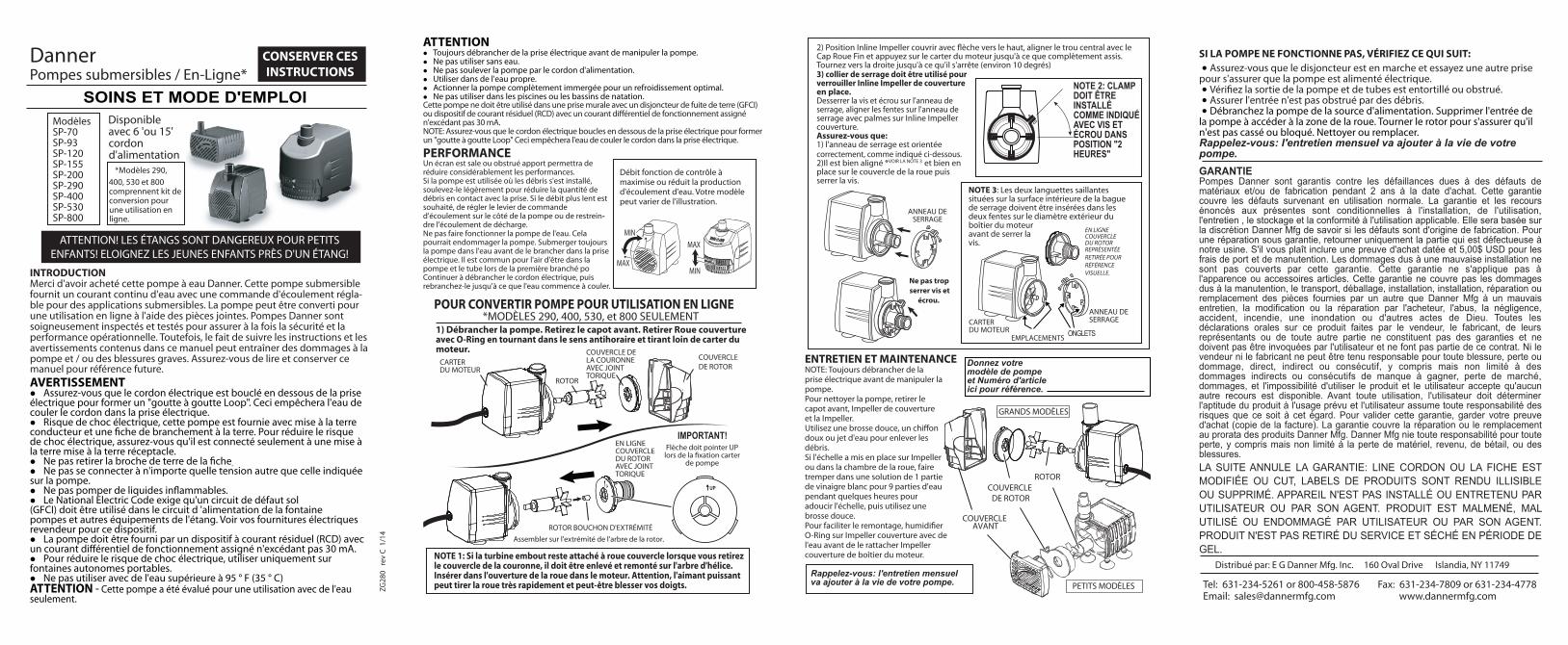
NOTE 3: The two protruding tabs located on the inside surface of the Ring Clamp must be inserted into the two slots on the outside diameter of the Motor Housing before tightening screw.
INLINE IMPELLER COVER SHOWN REMOVED FOR VISUAL REFERENCE.
SLOTS TABS
2) Position Inline Impeller cover with ARROW pointing UP, align the center hole with the Impeller End Cap and press into motor housing until completely seated. Turn clockwise until it stops (about 10 degrees).
NOTE 2: CLAMP MUST BE INSTALLED AS SHOWN WITH SCREW AND NUT IN “2 O’CLOCK” POSITION.
3) Ring clamp must be used to lock Inline Impeller Cover in place.Loosen Screw and Nut on Ring Clamp, align slots on Ring Clamp with Fins on Inline Impeller Cover.
Make certain that:1) Ring Clamp is oriented properly as shown below. 2) It is properly aligned *SEE NOTE 3 and completely seated over the Impeller cover then tighten screw.
Do not overtighten Screw and
Nut.
RING CLAMP
RING CLAMP
MOTOR HOUSING
Remember: Monthly maintenance will add to your pump’s life.
CAUTION Always disconnect from electrical outlet before handling the pump. Don’t operate without water. Do not lift the pump by the power cord. Operate in clean water only. Operate pump completely submerged for optimum cooling. Not for use in swimming pools or swimming ponds.This pump is only to be used in an outlet with a ground fault circuit interrupter (GFCI) or residual current device (RCD) with a rated residual operating current not exceeding 30 mA. NOTE: Ensure that the electrical cord loops below the electrical outlet to form a “Drip Loop” This will prevent water from running down the cord into the electrical outlet.
PERFORMANCEA clogged or dirty intake screen will greatly reduce performance.If the pump is used where debris has settled, raise it slightly to reduce the amount of debris contacting the intake. If slower flow is desired, adjust the flow control lever on the side of the pump or restrict the discharge flow.Do not run the pump out of the water. Doing so may damage the pump. Always submerge the pump in the water before plugging in the electrical outlet. It is common for air to be in the pump and tube when first plugged in. Continue to unplug the electrical cord and then plug it back in until water begins to flow.
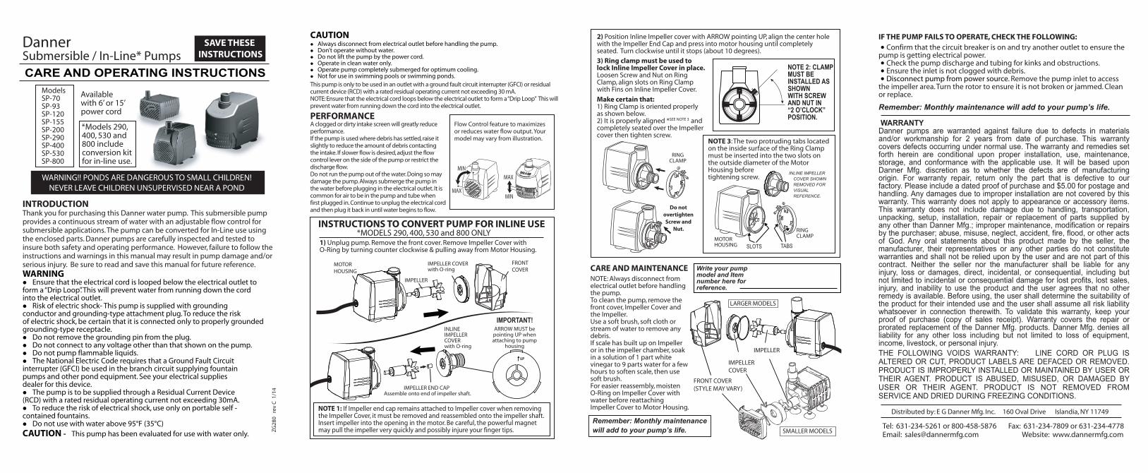
IMPELLER END CAP Assemble onto end of impeller shaft.
INLINE IMPELLER COVER with O-ring
IMPORTANT!ARROW MUST be pointing UP when attaching to pump
housing
1) Unplug pump. Remove the front cover. Remove Impeller Cover with O-Ring by turning counter clockwise & pulling away from Motor Housing.
INSTRUCTIONS TO CONVERT PUMP FOR INLINE USE
FRONTCOVER
IMPELLER
MOTOR HOUSING
IMPELLER COVER with O-ring
UP
NOTE 1: If Impeller end cap remains attached to Impeller cover when removing the Impeller Cover, it must be removed and reassembled onto the impeller shaft. Insert impeller into the opening in the motor. Be careful, the powerful magnet may pull the impeller very quickly and possibly injure your finger tips.
*MODELS 290, 400, 530 and 800 ONLY
Flow Control feature to maximizes or reduces water flow output. Your model may vary from illustration.
MAX
MINMAX
MIN
WARNING!! PONDS ARE DANGEROUS TO SMALL CHILDREN! NEVER LEAVE CHILDREN UNSUPERVISED NEAR A POND
Danner Submersible / In-Line* Pumps
INTRODUCTIONThank you for purchasing this Danner water pump. This submersible pump provides a continuous stream of water with an adjustable flow control for submersible applications. The pump can be converted for In-Line use using the enclosed parts. Danner pumps are carefully inspected and tested to insure both safety and operating performance. However, failure to follow the instructions and warnings in this manual may result in pump damage and/or serious injury. Be sure to read and save this manual for future reference.
SAVE THESE INSTRUCTIONS
CARE AND OPERATING INSTRUCTIONS
ZG28
0 r
ev C
1/1
4
Available with 6’ or 15’ power cord
*Models 290, 400, 530 and 800 include conversion kit for in-line use.
WARNING Ensure that the electrical cord is looped below the electrical outlet toform a “Drip Loop”. This will prevent water from running down the cordinto the electrical outlet. Risk of electric shock- This pump is supplied with groundingconductor and grounding-type attachment plug. To reduce the riskof electric shock, be certain that it is connected only to properly groundedgrounding-type receptacle. Do not remove the grounding pin from the plug. Do not connect to any voltage other than that shown on the pump. Do not pump flammable liquids. The National Electric Code requires that a Ground Fault Circuitinterrupter (GFCI) be used in the branch circuit supplying fountainpumps and other pond equipment. See your electrical suppliesdealer for this device. The pump is to be supplied through a Residual Current Device(RCD) with a rated residual operating current not exceeding 30mA. To reduce the risk of electrical shock, use only on portable self -contained fountains. Do not use with water above 95°F (35°C)CAUTION - This pump has been evaluated for use with water only.
Models SP-70 SP-93 SP-120SP-155 SP-200 SP-290 SP-400 SP-530 SP-800
Tel: 631-234-5261 or 800-458-5876 Fax: 631-234-7809 or 631-234-4778Email: [email protected] www.dannermfg.com
Distribué par: E G Danner Mfg. Inc. 160 Oval Drive Islandia, NY 11749
GARANTIEPompes Danner sont garantis contre les défaillances dues à des défauts de matériaux et/ou de fabrication pendant 2 ans à la date d'achat. Cette garantie couvre les défauts survenant en utilisation normale. La garantie et les recours énoncés aux présentes sont conditionnelles à l'installation, de l'utilisation, l'entretien , le stockage et la conformité à l'utilisation applicable. Elle sera basée sur la discrétion Danner Mfg de savoir si les défauts sont d'origine de fabrication. Pour une réparation sous garantie, retourner uniquement la partie qui est défectueuse à notre usine. S'il vous plaît inclure une preuve d'achat datée et 5,00$ USD pour les frais de port et de manutention. Les dommages dus à une mauvaise installation ne sont pas couverts par cette garantie. Cette garantie ne s'applique pas à l'apparence ou accessoires articles. Cette garantie ne couvre pas les dommages dus à la manutention, le transport, déballage, installation, installation, réparation ou remplacement des pièces fournies par un autre que Danner Mfg à un mauvais entretien, la modification ou la réparation par l'acheteur, l'abus, la négligence, accident, incendie, une inondation ou d'autres actes de Dieu. Toutes les déclarations orales sur ce produit faites par le vendeur, le fabricant, de leurs représentants ou de toute autre partie ne constituent pas des garanties et ne doivent pas être invoquées par l'utilisateur et ne font pas partie de ce contrat. Ni le vendeur ni le fabricant ne peut être tenu responsable pour toute blessure, perte ou dommage, direct, indirect ou consécutif, y compris mais non limité à des dommages indirects ou consécutifs de manque à gagner, perte de marché, dommages, et l'impossibilité d'utiliser le produit et le utilisateur accepte qu'aucun autre recours est disponible. Avant toute utilisation, l'utilisateur doit déterminer l'aptitude du produit à l'usage prévu et l'utilisateur assume toute responsabilité des risques que ce soit à cet égard. Pour valider cette garantie, garder votre preuve d'achat (copie de la facture). La garantie couvre la réparation ou le remplacement au prorata des produits Danner Mfg. Danner Mfg nie toute responsabilité pour toute perte, y compris mais non limité à la perte de matériel, revenu, de bétail, ou des blessures.LA SUITE ANNULE LA GARANTIE: LINE CORDON OU LA FICHE EST MODIFIÉE OU CUT, LABELS DE PRODUITS SONT RENDU ILLISIBLE OU SUPPRIMÉ. APPAREIL N'EST PAS INSTALLÉ OU ENTRETENU PAR UTILISATEUR OU PAR SON AGENT. PRODUIT EST MALMENÉ, MAL UTILISÉ OU ENDOMMAGÉ PAR UTILISATEUR OU PAR SON AGENT. PRODUIT N'EST PAS RETIRÉ DU SERVICE ET SÉCHÉ EN PÉRIODE DE GEL.
SI LA POMPE NE FONCTIONNE PAS, VÉRIFIEZ CE QUI SUIT:
Assurez-vous que le disjoncteur est en marche et essayez une autre prise pour s'assurer que la pompe est alimenté électrique.Assurer l'entrée n'est pas obstrué par des débris.Débranchez la pompe de la source d'alimentation. Supprimer l'entrée de la pompe à accéder à la zone de la roue. Tourner le rotor pour s'assurer qu'il n'est pas cassé ou bloqué. Nettoyer ou remplacer.Rappelez-vous: l'entretien mensuel va ajouter à la vie de votre pompe.
ENTRETIEN ET MAINTENANCENOTE: Toujours débrancher de la prise électrique avant de manipuler la pompe.Pour nettoyer la pompe, retirer le capot avant, Impeller de couverture et la Impeller.
doux ou jet d'eau pour enlever les débris.Si l'échelle a mis en place sur Impeller ou dans la chambre de la roue, faire tremper dans une solution de 1 partie de vinaigre blanc pour 9 parties d'eau pendant quelques heures pour adoucir l'échelle, puis utilisez une brosse douce.
O-Ring sur Impeller couverture avec de l'eau avant de le rattacher Impeller couverture de boîtier du moteur.
Donnez votre modèle de pompe et Numéro d'article ici pour référence.
COUVERCLE AVANT
COUVERCLE DE ROTOR
ROTOR
PETITS MODÈLES
GRANDS MODÈLES
NOTE 3: Les deux languettes saillantes situées sur la surface intérieure de la bague de serrage doivent être insérées dans les deux fentes sur le diamètre extérieur du boîtier du moteur avant de serrer la vis.
EN LIGNECOUVERCLE DU ROTORREPRÉSENTÉE RETIRÉE POUR RÉFÉRENCE VISUELLE.
ONGLETS
Cap Roue Fin et appuyez sur le carter du moteur jusqu'à ce que complètement assis. Tournez vers la droite jusqu'à ce qu'il s'arrête (environ 10 degrés)
NOTE 2: CLAMP DOIT ÊTREINSTALLÉ COMME INDIQUÉAVEC VIS ET ÉCROU DANSPOSITION "2 HEURES"
3) collier de serrage doit être utilisé pour verrouiller Inline Impeller de couverture en place.Desserrer la vis et écrou sur l'anneau de serrage, aligner les fentes sur l'anneau de serrage avec palmes sur Inline Impeller couverture.Assurez-vous que:1) l'anneau de serrage est orientée correctement, comme indiqué ci-dessous. 2)Il est bien aligné *VOIR LA NOTE 3 et bien en place sur le couvercle de la roue puis serrer la vis.
Ne pas trop serrer vis et
écrou.
ANNEAU DE SERRAGE
ANNEAU DE SERRAGECARTER
DU MOTEUR
Rappelez-vous: l'entretien mensuel va ajouter à la vie de votre pompe.
EMPLACEMENTS
ATTENTION Toujours débrancher de la prise électrique avant de manipuler la pompe. Ne pas utiliser sans eau. Ne pas soulever la pompe par le cordon d'alimentation. Utiliser dans de l'eau propre. Actionner la pompe complètement immergée pour un refroidissement optimal. Ne pas utiliser dans les piscines ou les bassins de natation.Cette pompe ne doit être utilisé dans une prise murale avec un disjoncteur de fuite de terre (GFCI)
n'excédant pas 30 mA.NOTE: Assurez-vous que le cordon électrique boucles en dessous de la prise électrique pour former un "goutte à goutte Loop" Ceci empêchera l'eau de couler le cordon dans la prise électrique.
PERFORMANCEUn écran est sale ou obstrué apport permettra de réduire considérablement les performances.Si la pompe est utilisée où les débris s'est installé, soulevez-le légèrement pour réduire la quantité de débris en contact avec la prise. Si le débit plus lent est souhaité, de régler le levier de commande d'écoulement sur le côté de la pompe ou de restrein-dre l'écoulement de décharge.Ne pas faire fonctionner la pompe de l'eau. Cela pourrait endommager la pompe. Submerger toujours la pompe dans l'eau avant de le brancher dans la prise électrique. Il est commun pour l'air d'être dans la pompe et le tube lors de la première branché po Continuer à débrancher le cordon électrique, puis rebranchez-le jusqu'à ce que l'eau commence à couler.
ROTOR BOUCHON D'EXTRÉMITÉ
Assembler sur l'extrémité de l'arbre de la rotor.
EN LIGNECOUVERCLE DU ROTORAVEC JOINT TORIQUE
IMPORTANT!Flèche doit pointer UP
de pompe
1) Débrancher la pompe. Retirez le capot avant. Retirer Roue couverture avec O-Ring en tournant dans le sens antihoraire et tirant loin de carter dumoteur.
POUR CONVERTIR POMPE POUR UTILISATION EN LIGNE
COUVERCLEDE ROTOR
ROTOR
COUVERCLE DE LA COURONNE AVEC JOINT TORIQUE
UP
NOTE 1: Si la turbine embout reste attaché à roue couvercle lorsque vous retirez le couvercle de la couronne, il doit être enlevé et remonté sur l'arbre d'hélice. Insérer dans l'ouverture de la roue dans le moteur. Attention, l'aimant puissant peut tirer la roue très rapidement et peut-être blesser vos doigts.
*MODÈLES 290, 400, 530, et 800 SEULEMENT
Débit fonction de contrôle à maximise ou réduit la production d'écoulement d'eau. Votre modèle peut varier de l'illustration.
MAX
MINMAX
MIN
CARTER DU MOTEUR
ATTENTION! LES ÉTANGS SONT DANGEREUX POUR PETITS ENFANTS! ELOIGNEZ LES JEUNES ENFANTS PRÈS D'UN ÉTANG!
Danner Pompes submersibles / En-Ligne*
INTRODUCTIONMerci d'avoir acheté cette pompe à eau Danner. Cette pompe submersible fournit un courant continu d'eau avec une commande d'écoulement régla-ble pour des applications submersibles. La pompe peut être converti pour une utilisation en ligne à l'aide des pièces jointes. Pompes Danner sont soigneusement inspectés et testés pour assurer à la fois la sécurité et la performance opérationnelle. Toutefois, le fait de suivre les instructions et les avertissements contenus dans ce manuel peut entraîner des dommages à la pompe et / ou des blessures graves. Assurez-vous de lire et conserver ce manuel pour référence future.
CONSERVER CESINSTRUCTIONS
SOINS ET MODE D'EMPLOI
ZG28
0 r
ev C
1/1
4
Disponible avec 6 'ou 15' cordon d'alimentation
*Modèles 290, 400, 530 et 800 comprennent kit de conversion pour une utilisation en ligne.
AVERTISSEMENT Assurez-vous que le cordon électrique est bouclé en dessous de la prise électrique pour former un "goutte à goutte Loop". Ceci empêchera l'eau de couler le cordon dans la prise électrique. Risque de choc électrique, cette pompe est fournie avec mise à la terre
de choc électrique, assurez-vous qu'il est connecté seulement à une mise à la terre mise à la terre réceptacle. Ne pas se connecter à n'importe quelle tension autre que celle indiquée sur la pompe. Le National Electric Code exige qu'un circuit de défaut sol(GFCI) doit être utilisé dans le circuit d 'alimentation de la fontainepompes et autres équipements de l'étang. Voir vos fournitures électriquesrevendeur pour ce dispositif. La pompe doit être fourni par un dispositif à courant résiduel (RCD) avec
Pour réduire le risque de choc électrique, utiliser uniquement sur fontaines autonomes portables. Ne pas utiliser avec de l'eau supérieure à 95 ° F (35 ° C)ATTENTION - Cette pompe a été évalué pour une utilisation avec de l'eau seulement.
Modèles SP-70 SP-93 SP-120SP-155 SP-200 SP-290 SP-400 SP-530 SP-800