Embed Size (px)
Citation preview
TCEQ-0585-Instructions (Rev. 10-01-04)
Instructions to Geologistsfor
Geologic Assessmentson the
Edwards Aquifer Recharge/Transition Zones
CONTENTS
I. Overview and Changes From Previous Versions . . . . . . . . . . . . . . . . . . . . . . . . . . . . . . . . . . . . 1
II. General Instructions . . . . . . . . . . . . . . . . . . . . . . . . . . . . . . . . . . . . . . . . . . . . . . . . . . . . . . . . . . 1A. Procedure For Conducting A Geologic Assessment . . . . . . . . . . . . . . . . . . . . . . . . . . . 2
Research information . . . . . . . . . . . . . . . . . . . . . . . . . . . . . . . . . . . . . . . . . . . . . . . 2Perform a field survey . . . . . . . . . . . . . . . . . . . . . . . . . . . . . . . . . . . . . . . . . . . . . . . 3Evaluate data, make conclusions, and make a report . . . . . . . . . . . . . . . . . . . . . . . 4
B. Attachments . . . . . . . . . . . . . . . . . . . . . . . . . . . . . . . . . . . . . . . . . . . . . . . . . . . . . . . . . . 5Soils . . . . . . . . . . . . . . . . . . . . . . . . . . . . . . . . . . . . . . . . . . . . . . . . . . . . . . . . . . . . 5Site geologic map . . . . . . . . . . . . . . . . . . . . . . . . . . . . . . . . . . . . . . . . . . . . . . . . . . 5Stratigraphic column . . . . . . . . . . . . . . . . . . . . . . . . . . . . . . . . . . . . . . . . . . . . . . . . 5Geologic assessment table . . . . . . . . . . . . . . . . . . . . . . . . . . . . . . . . . . . . . . . . . . . 6Narrative description of site geology . . . . . . . . . . . . . . . . . . . . . . . . . . . . . . . . . . . . 6
III. Detailed Instructions For Elements Requiring Further Clarification . . . . . . . . . . . . . . . . . . . . . . . 7A. Completing the Geologic Assessment Table . . . . . . . . . . . . . . . . . . . . . . . . . . . . . . . . . . 7
1A. Feature ID . . . . . . . . . . . . . . . . . . . . . . . . . . . . . . . . . . . . . . . . . . . . . . . . . . 71B. Latitude and 1C longitude. . . . . . . . . . . . . . . . . . . . . . . . . . . . . . . . . . . . . . 72A. Feature type . . . . . . . . . . . . . . . . . . . . . . . . . . . . . . . . . . . . . . . . . . . . . . . . 82B. Points for feature type . . . . . . . . . . . . . . . . . . . . . . . . . . . . . . . . . . . . . . . . 103. Geologic formation . . . . . . . . . . . . . . . . . . . . . . . . . . . . . . . . . . . . . . . . . . 104. Feature dimensions . . . . . . . . . . . . . . . . . . . . . . . . . . . . . . . . . . . . . . . . . 105. Trend . . . . . . . . . . . . . . . . . . . . . . . . . . . . . . . . . . . . . . . . . . . . . . . . . . . . 106. Density (applicable to SF, Z, and O) . . . . . . . . . . . . . . . . . . . . . . . . . . . . . 117. Aperture (applicable to SF, Z, and O) . . . . . . . . . . . . . . . . . . . . . . . . . . . . 118A. Infilling . . . . . . . . . . . . . . . . . . . . . . . . . . . . . . . . . . . . . . . . . . . . . . . . . . . . 118B. Relative infiltration rate . . . . . . . . . . . . . . . . . . . . . . . . . . . . . . . . . . . . . . . 129. Total feature characteristic points . . . . . . . . . . . . . . . . . . . . . . . . . . . . . . . 1610. Sensitivity . . . . . . . . . . . . . . . . . . . . . . . . . . . . . . . . . . . . . . . . . . . . . . . . . 1611. Catchment area . . . . . . . . . . . . . . . . . . . . . . . . . . . . . . . . . . . . . . . . . . . . 1612. Topography . . . . . . . . . . . . . . . . . . . . . . . . . . . . . . . . . . . . . . . . . . . . . . . 16
B. GPS Requirements . . . . . . . . . . . . . . . . . . . . . . . . . . . . . . . . . . . . . . . . . . . . . . . . . . . . 16C. Instructions For Excavation Using Heavy Equipment . . . . . . . . . . . . . . . . . . . . . . . . . . 17D. Features Encountered During Sewer Construction . . . . . . . . . . . . . . . . . . . . . . . . . . . 18
IV. Glossary . . . . . . . . . . . . . . . . . . . . . . . . . . . . . . . . . . . . . . . . . . . . . . . . . . . . . . . . . . . . . . . . . 18
V. Citations For Sources of Further Information . . . . . . . . . . . . . . . . . . . . . . . . . . . . . . . . . . . . . . 25
TCEQ-0585-Instructions (Rev. 10-01-04)
TABLES
Table 1. Stratigraphic nomenclature and standard abbreviations . . . . . . . . . . . . . . . . . . . . . . . . . . 5Table 2. Feature abbreviations, types, and points assigned . . . . . . . . . . . . . . . . . . . . . . . . . . . . . . 8Table 3. Feature infilling, key to column 8A . . . . . . . . . . . . . . . . . . . . . . . . . . . . . . . . . . . . . . . . . 11Table 4. Classification of features encountered during sewer construction . . . . . . . . . . . . . . . . . 18
FIGURES
Figure 2. Cumulative frequency maximum radius of the cave footprint from the cave entrancemeasured from 236 mapped caves in the Edwards recharge zone in the Texas SpeleologicalSurvey files. . . . . . . . . . . . . . . . . . . . . . . . . . . . . . . . . . . . . . . . . . . . . . . . . . . . . . . . . . . . . . . . . . 20Figure 3. Modeling results showing time in days for ponded water of various initial heads to drainthrough soil under background conditions. . . . . . . . . . . . . . . . . . . . . . . . . . . . . . . . . . . . . . . . . . . 22Figure 4. EAPP - Solution Cavity Form . . . . . . . . . . . . . . . . . . . . . . . . . . . . . . . . . . . . . . . . . . . . . 29
TCEQ-0585-Instructions (Rev. 10-01-04) Page 1 of 34
I. Overview and Changes From Previous Versions
The Edwards Aquifer rules [Title 30 Texas Administrative Code (TAC) Chapter 213] wererevised June 1, 1999. If you have not reviewed a copy of the rules since that date, please obtain acopy of the current rules. Some significant changes in the rules include: The assessment of areageology is now called “geologic assessment.” A downgradient geologic assessment is not requiredfor Edwards Aquifer Protection Plans received on or after June 1, 1999. Some terms have beenredefined and are included in the glossary.
These “Instructions to Geologists” have been revised to improve the effectiveness withoutcompromising the efficiency of the geologic assessment of sensitive features in the EdwardsAquifer recharge zone.
The major changes to the instructions are: (1) To eliminate the category “possibly sensitive”. Geologists doing the assessment are
not asked to express a high degree of certainty about flow characteristics andcommunication to the subsurface to rank features as sensitive, as uncertainty isalready expressed in the language of the Edwards Aquifer rules.
(2) To simplify the assessment to include only three variables: a classification by featuretype, orientation with respect to structure, a field-based assessment of relativeinfiltration rate,
(3) To increase emphasis on matching appropriate engineering responses to sensitivefeatures,
(4) To evaluate features encountered during sewer construction to identify those whereflow should be maintained,
(5) To increase the guidance provided in the instructions, (6) To reduce variability in assessment by better defining the criteria on which to evaluate
relative infiltration rate.
II. General Instructions
This section overviews the expectations for collecting information from the literature anddetailed field observations for the entire geologic assessment. As specified in the rules, theseinstructions are intended to guide geologists in preparing geologic assessments, completingrequired forms, and determining which of the geologic and manmade features are sensitive. Thepurpose of this report is to identify all potential pathways for contaminant movement to theEdwards Aquifer and provide sufficient geologic information so that the appropriate BestManagement Practices (BMPs) can be proposed in the Edwards Aquifer Protection Plan(EAPP).
The Edwards Aquifer rules require that this report is to be prepared by a geologist. Therules specify that the qualifications of the geologist are that he or she “has received abaccalaureate or post-graduate degree in the natural science of geology from an accrediteduniversity and has training and experience in groundwater hydrology and related fields, or hasdemonstrated such qualifications by registration or licensing by state, professional certification,or has completed an accredited university program that enables that individual to make soundprofessional judgments regarding the identification of sensitive features located in the rechargezone or the transition zone.” After September 1, 2003, geologists conducting assessments areexpected to be licensed according to the provisions of Texas Geoscience Practice Act. Inaddition, the geologist should be familiar with standard karst, hydrology, and Edwards rechargezone literature. Citations to some representative source are provided with these instructions.
TCEQ-0585-Instructions (Rev. 10-01-04) Page 2 of 34
More Edwards-specific information about terms in italics is provided in the Glossary providedwith these instructions.
Single-family residential subdivisions constructed on less than 10 acres are exempt fromthis requirement. The assessment must include the path of any proposed sewer line thatextends outside the Water Pollution Abatement Plan (WPAP) assessed area, plus 50 feet oneither side.
Answer all questions. If some items do not apply, provide a brief explanation. Thecomments "Not applicable" or "See Item XX above" are not acceptable. The comment "Seeattached...." is only valid for referencing required plans or maps. The application will be returnedto your client if all items on these instructions are not adequately addressed.
A. Procedure For Conducting A Geologic Assessment
The general procedure for conducting a geologic assessment is to perform the followingsteps: research information, perform a field survey, evaluate data, return to the site if necessary,make conclusions, and make a report with your feature assessments and recommendations. Ageologic map, preliminary data input into the Geologic Assessment Table, notes, photographsand/or sketches should be made while in the field. These data may be used and included in yourfinal report.
Research information
Published reports and maps of area geology should be studied prior to performing thefield survey. A literature or database search should be conducted for the presence ofdocumented caves or other karst features on the property or in proximity to the propertyboundary. Information may be found about known caves, such as mapped extent, depth orelevation or orientation, on the subject property or on adjacent tracts. Some commonly useddata sources for geologic maps and cave location and interpretation are included in the“Citations for Sources of Further information” in these Instructions.
Evaluate former land use practices and modifications. Interview persons knowledgeableabout historical activities such as well drilling, irrigation or water control ditches or trenches, pitor structure construction, episodes of brush clearing and tree pulling, and cave filling orexcavation. In ranches that have been occupied for a long time, manmade features can bedegraded and overgrown and be confused with natural features. Human activities also mayobscure indicators of natural processes that otherwise could be used to determine the sensitivityof a feature.
Aerial photos may be examined for the presence of structural features that should befield checked and plotted on the map.
Perform a field survey
The entire subject site must be walked to survey the ground surface for the presence ofgeologic and manmade features. It is recommended that the site be walked systematically inspaced transects 50 feet apart or smaller, paying close attention to streambeds and structuralfeatures observed on aerial photographs. The transect pattern should be adapted to insure thatthe geologist is able to see features and will vary with topography and vegetation on the site.Streambeds, including dry drainages, are significant because runoff is focused to them. Notonly are features in streambeds likely to receive large volumes of recharge, but they are likely to
TCEQ-0585-Instructions (Rev. 10-01-04) Page 3 of 34
be part of hydrologically integrated flowpaths because past flow has preferentially enlarged andmaintained conduits. Features in streambeds are likely to be obscured by transported soil orgravel (Swallets or swallow hole). Structural features such as faults and fracture zones haveinfluenced karst processes in the Edwards recharge zone, and awareness of these structuresmay be helpful in completing a high-quality assessment. The assessment must include the pathof any proposed sewer line that extends outside of the WPAP assessed area, plus 50 feet oneither side. Any features identified should be marked where possible with flagging or stakes,accurately located, preferably using a GPS (see detailed instructions IIIB below), assigned aunique number, the location accurately plotted on the geologic map, data entered in the GeologicAssessment Table, and supplementary interpretative data recorded in the narrative descriptionof site geology.
The intensity and schedule of investigations should be adapted by the geologist and hisclient to meet the specific requirements of the site. Effort should be focused in order to (1)efficiently and correctly separate sensitive from not sensitive features and (2) provide adequateinformation about the sensitive features to the engineer and site designer so that appropriateBMP’s can be designed. In some sites, it is likely that a return visit to collect additionalinformation about certain features will be needed to accomplish these goals.
Tests such as excavation, cave mapping, infiltrometer tests, geophysical studies, ortracer studies are not required for the geologic assessment of any feature. However, if initialassessment leaves significant uncertainty regarding the characteristics of a feature, thegeologist is required by the rules to err on the side of being overly protective and rank the featureas sensitive where “potential for hydraulic interconnectedness exists and rapid infiltration mayoccur.” Testing is described as a mechanism with potential for reducing the ranking of somefeatures from sensitive to not sensitive that the geologist or his client can choose to perform. Afeature can be described as not sensitive by showing that the feature is not permeable, does nothave potential for interconnectedness between the surface and the Edwards aquifer, and thatrapid infiltration cannot occur. Geologists and clients may choose to schedule a Phase Iassessment that locates and evaluates all the features and a Phase II follow-up on specificfeatures that refines the evaluation. A Phase II assessment is not required to complete ageologic assessment. However, if excavation, cave mapping, infiltrometer tests, tracer studies,geophysical studies, or other follow-up tests are conducted, the results must be presented aspart of the geologic assessment.
Features in areas that are going to be protected, for example, drainageways that willreceive only high-quality water or areas that will be protected with setbacks or karst preserves,require no especially elaborate or Phase II assessments. Characteristics of features in theseareas should be mapped and described, but it is acceptable to use a designation of “zone” tosave labor of assessing numerous associated and genetically similar features if an appropriatelyprotective BMP will be implemented over an area.
Make note of the initial condition of the feature upon your first encounter, particularly thenature of undisturbed surface and sediment filling. Sketches or photographs may beappropriate. Does it appear to be in natural condition or has the area been disrupted by activitiessuch as construction or surveying? These initial observations may be modified and improved asanalysis of the feature continues.
Classify the feature according to type, and collect the data needed to complete theGeologic Assessment Table (see detailed instruction IIIA). In order to define the type and extentof the feature, at least a few minutes of probing (only use a non-conducting probe), hand
TCEQ-0585-Instructions (Rev. 10-01-04) Page 4 of 34
clearing, or hand excavation will probably be required. Removal of loose rocks by hand (nobackhoes or jack hammers) around a natural opening may be appropriate. Special attentionshould be given to the assessment of relative infiltration rate, as this factor is critical indetermining whether a feature is sensitive. In some cases a return visit to use specializedequipment or to complete the investigation may be needed. If geologists and their clients decidethat tracer or infiltration tests would be helpful for site assessments, the tests should bedesigned to use good scientific protocols. Testing may require permitting from TCEQunderground injection control (UIC) for a Class V injection well. Comments in the narrativedescription of site geology are expected for each feature to justify the relative infiltration rateassigned and to support your rating. Excavation with heavy equipment requires prior approval(see detailed instructions IIIC).
While still in the field, assess the feature in its geologic and physiographic context. Thispart of the assessment will provide information to the engineer to design the appropriate BMP. Isthe feature elongated along a fracture? Are other features recognized along this trend? Is it partof an assemblage of karst-related features? In this case it should be classified as part of a zoneand a BMP design applied to the whole area rather than isolated features. Drainage areasshould be estimated in the field and checked against the best available contour maps. Ifadditional information not apparent on the contour map is used to estimate a small drainagearea, for example subtle geomorphic features, plot them on the map, add an additional map at aconvenient scale, or explain in the narrative description. Identify the local topographic setting (forexample, wall, hill top, hillside, drainage, floodplain, streambed), the extent to which waterappears to have been directed toward the feature and the potential that it can be in a channelduring high flow.
If caves are identified during the assessment, a map showing scale or dimensionsshould be made of its extent and relationship to surface features, and/or relationship to utilities orother manmade objects. The projected surface cave footprint should be marked on the sitegeologic map. If a cave is not entered and mapped, reasonable efforts should be made todetermine the area assumed to be underlain by cave passage. This could be based ongeophysical or hydrologic measurements or on the dimensions of typical cave footprints. Explainthe source of data in your comments.
Evaluate data, make conclusions, and make a report
Evaluate your data by completing the Geologic Assessment Table and considering theresults. Note that the Edwards Aquifer rules define sensitive features as those that havepotential for interconnectedness between the surface and the Edwards aquifer and where rapidinfiltration to the subsurface may occur (bold added). Geologists making the assessment arenot asked to express a high degree of certainty that interconnectedness and rapid infiltrationactually occur in order to rank features as sensitive. Observed variations in the topographic,geologic, and hydrologic setting of sensitive features should be provided by the geologist so thatall variables can be considered when BMP’s are designed.
B. Attachments
The geologic assessment form must include the following attachments:Soils descriptionSite geologic mapStratigraphic column
TCEQ-0585-Instructions (Rev. 10-01-04) Page 5 of 34
Geologic assessment table Narrative description of site geology
Soils description
For a soil’s ability to transmit or impede fluid flow into the subsurface, use the hydrologicsoil groups, as defined by SCS soil scientists in Appendix B (Soil Series and Hydrologic SoilGroups) of Urban Hydrology for Small Watersheds, Technical Release No. 55, engineeringDivision, Soil Conservation Service, US Department of Agriculture, January 1975.
Site geologic map
The site geologic map must illustrate the outcrop of surface geologic units and thelocation and extent of all geologic and manmade features. The map should specifically locatenatural and manmade features listed in the Geologic Assessment Table as described below andany other features sensitive to pollution. It should show springs, all intermittent drainages andflowing streams, and the 100-year floodplain, if it has been mapped within the site. The sitegeologic map must be the same scale as the applicant will use for the WPAP site plan.
The site geologic map should be compiled from information gained from fieldobservations. Published maps of the region should only be used as a general reference andshould not be relied upon to be accurate for individual sites. If available, previous mappingshould be cited. Mappable units for the site geologic map should, at minimum, be presented atthe formation (Person, Kainer, etc.) level. USGS hydrogeologic units may be included wherethey have been mapped. Indicators of the dominant structural trend in the area (faults, fracturezones, lineaments, etc.), should be shown. Faults should be marked with a solid line whereexposed, dashed where inferred, and dotted where buried. Core from construction borings maybe helpful in mapping site geology.
Stratigraphic column
The stratigraphic column must show the formations, members, and thickness in the maparea. The symbols and abbreviations used must match those used on the geologic map.
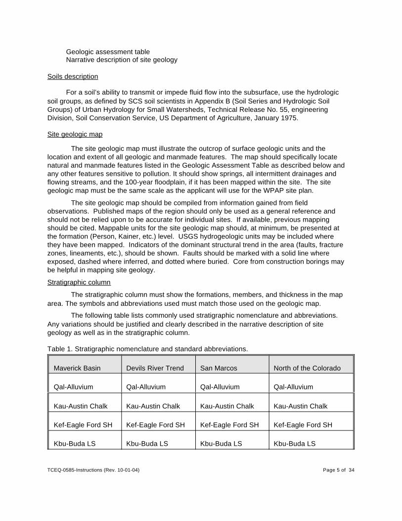
The following table lists commonly used stratigraphic nomenclature and abbreviations.Any variations should be justified and clearly described in the narrative description of sitegeology as well as in the stratigraphic column.
Table 1. Stratigraphic nomenclature and standard abbreviations.
Maverick Basin Devils River Trend San Marcos North of the Colorado
Qal-Alluvium Qal-Alluvium Qal-Alluvium Qal-Alluvium
Kau-Austin Chalk Kau-Austin Chalk Kau-Austin Chalk Kau-Austin Chalk
Kef-Eagle Ford SH Kef-Eagle Ford SH Kef-Eagle Ford SH Kef-Eagle Ford SH
Kbu-Buda LS Kbu-Buda LS Kbu-Buda LS Kbu-Buda LS
TCEQ-0585-Instructions (Rev. 10-01-04) Page 6 of 34
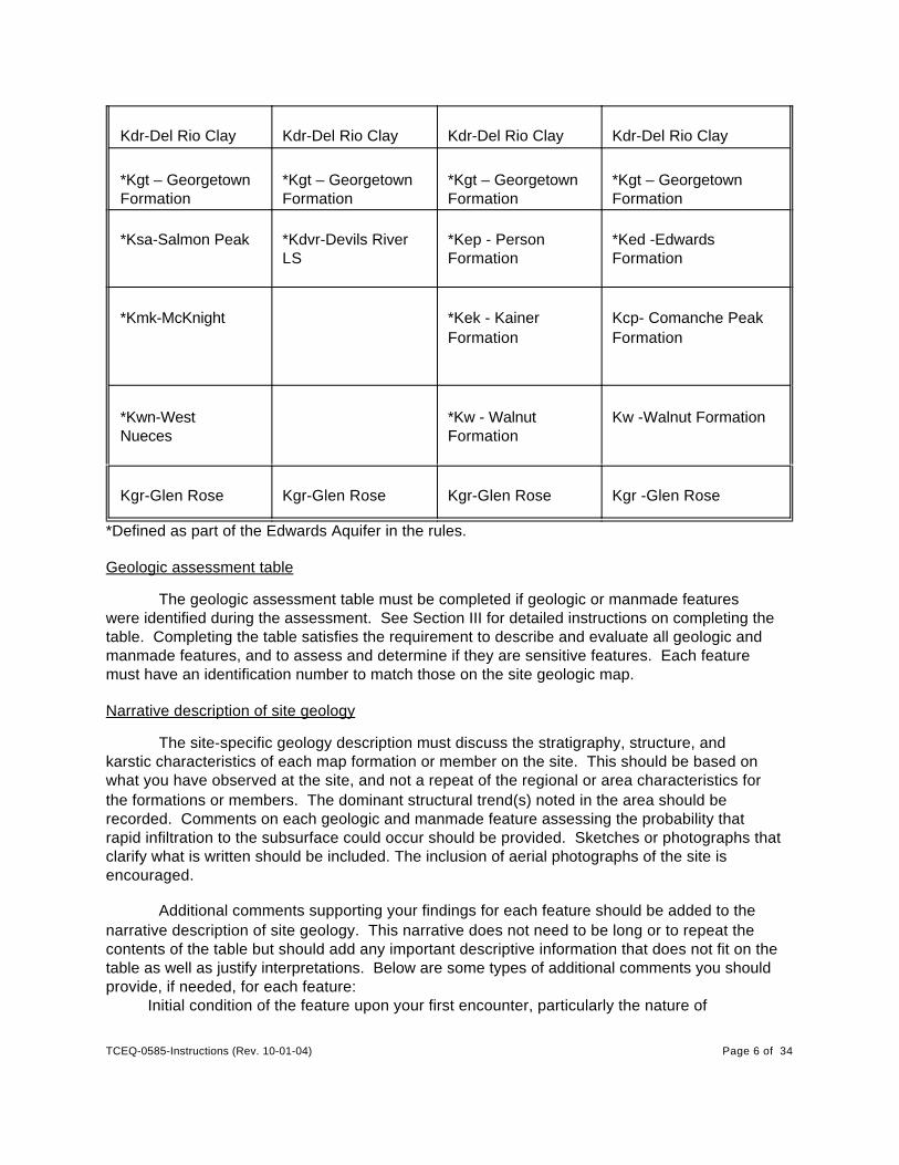
Kdr-Del Rio Clay Kdr-Del Rio Clay Kdr-Del Rio Clay Kdr-Del Rio Clay
*Kgt – GeorgetownFormation
*Kgt – GeorgetownFormation
*Kgt – GeorgetownFormation
*Kgt – GeorgetownFormation
*Ksa-Salmon Peak *Kdvr-Devils RiverLS
*Kep - PersonFormation
*Ked -EdwardsFormation
*Kmk-McKnight *Kek - KainerFormation
Kcp- Comanche PeakFormation
*Kwn-WestNueces
*Kw - WalnutFormation
Kw -Walnut Formation
Kgr-Glen Rose Kgr-Glen Rose Kgr-Glen Rose Kgr -Glen Rose
*Defined as part of the Edwards Aquifer in the rules.
Geologic assessment table
The geologic assessment table must be completed if geologic or manmade featureswere identified during the assessment. See Section III for detailed instructions on completing thetable. Completing the table satisfies the requirement to describe and evaluate all geologic andmanmade features, and to assess and determine if they are sensitive features. Each featuremust have an identification number to match those on the site geologic map.
Narrative description of site geology
The site-specific geology description must discuss the stratigraphy, structure, andkarstic characteristics of each map formation or member on the site. This should be based onwhat you have observed at the site, and not a repeat of the regional or area characteristics forthe formations or members. The dominant structural trend(s) noted in the area should berecorded. Comments on each geologic and manmade feature assessing the probability thatrapid infiltration to the subsurface could occur should be provided. Sketches or photographs thatclarify what is written should be included. The inclusion of aerial photographs of the site isencouraged.
Additional comments supporting your findings for each feature should be added to thenarrative description of site geology. This narrative does not need to be long or to repeat thecontents of the table but should add any important descriptive information that does not fit on thetable as well as justify interpretations. Below are some types of additional comments you shouldprovide, if needed, for each feature:
Initial condition of the feature upon your first encounter, particularly the nature of
TCEQ-0585-Instructions (Rev. 10-01-04) Page 7 of 34
undisturbed surface and feature infilling. Does it appear to be in natural conditionor has the area been disrupted by activities such as construction or surveying?
Caves: Note all evidence regarding extent and/or depth of cave, and source ofinformation.
Fault and fault zones: Note should be made regarding all supporting evidence fordelineating the fault, i.e., field evidence, air photos, and/or published sources.
Manmade features: Describe type and condition of feature and the reason for yourassessment, for example, from an interview or from your authorized excavation.
Relative infiltration rate: Present evidence that justifies assigned the probability of rapidinfiltration at the feature.
Photographs or sketches to clarify and support verbal description.Explanation of your thinking and needed detail to support design of a BMP.
III. Detailed Instructions For Elements Requiring Further Clarification
A. Completing the Geologic Assessment Table
This section clarifies terms and abbreviations and includes instructions for the appropriateusage of the geologic assessment table for describing and assessing geologic and manmadefeatures. The numbered items listed below correspond to the numbered columns on the table.
1A. Feature ID
Assign identification numbers to the features identified in the assessment. On the Tableand the site geologic map, number each geologic and manmade feature consecutively, forexample, S-1, S-2, S-3, S-4.
If a literature search, personal knowledge, visual inspection, or other information sourceidentifies downgradient features in proximity to the property boundary, then they should be notedin the report.
1B. Latitude and 1C longitude.
Provide coordinates in latitude and longitude in degrees, minutes, and decimal seconds foreach feature either by GPS measurement or other appropriate measurement techniques.Provide details of location data collection following detailed instruction IIIB (GPS Requirements)below. For aerially extensive features such as zones or faults, list one point location in the table. Select a point that will uniquely identify the feature, for example center, corner, or a locationwhere the feature is accessible or clearly visible. The extent of the feature should be shown onthe map. Additional location information may be listed in the narrative.
2A. Feature type
Enter the abbreviation that best matches the feature from Table 2 using the definitionsbelow. If more than one type is appropriate, you should hyphenate the feature type. Documentuncertainties in the description of this feature in the narrative description of site geology.Regardless of size or classification, any feature where rapid infiltration to the subsurface isindicated should be mapped. The geologist is expected to be familiar with these features usingthe glossary, karst text books, course work, and field experience.
TCEQ-0585-Instructions (Rev. 10-01-04) Page 8 of 34
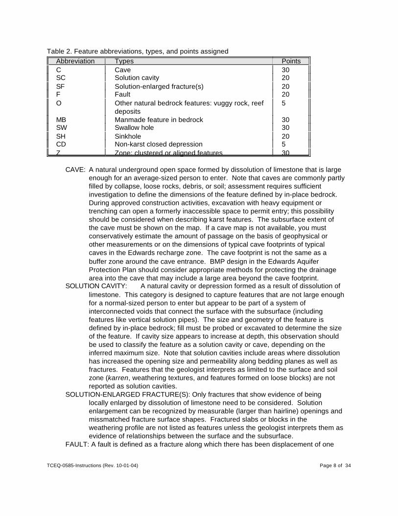
Table 2. Feature abbreviations, types, and points assignedAbbreviation Types PointsC Cave 30SC Solution cavity 20SF Solution-enlarged fracture(s) 20F Fault 20O Other natural bedrock features: vuggy rock, reef
deposits5
MB Manmade feature in bedrock 30SW Swallow hole 30SH Sinkhole 20CD Non-karst closed depression 5Z Zone: clustered or aligned features 30
CAVE: A natural underground open space formed by dissolution of limestone that is largeenough for an average-sized person to enter. Note that caves are commonly partlyfilled by collapse, loose rocks, debris, or soil; assessment requires sufficientinvestigation to define the dimensions of the feature defined by in-place bedrock. During approved construction activities, excavation with heavy equipment ortrenching can open a formerly inaccessible space to permit entry; this possibilityshould be considered when describing karst features. The subsurface extent ofthe cave must be shown on the map. If a cave map is not available, you mustconservatively estimate the amount of passage on the basis of geophysical orother measurements or on the dimensions of typical cave footprints of typicalcaves in the Edwards recharge zone. The cave footprint is not the same as abuffer zone around the cave entrance. BMP design in the Edwards AquiferProtection Plan should consider appropriate methods for protecting the drainagearea into the cave that may include a large area beyond the cave footprint.
SOLUTION CAVITY: A natural cavity or depression formed as a result of dissolution oflimestone. This category is designed to capture features that are not large enoughfor a normal-sized person to enter but appear to be part of a system ofinterconnected voids that connect the surface with the subsurface (includingfeatures like vertical solution pipes). The size and geometry of the feature isdefined by in-place bedrock; fill must be probed or excavated to determine the sizeof the feature. If cavity size appears to increase at depth, this observation shouldbe used to classify the feature as a solution cavity or cave, depending on theinferred maximum size. Note that solution cavities include areas where dissolutionhas increased the opening size and permeability along bedding planes as well asfractures. Features that the geologist interprets as limited to the surface and soilzone (karren, weathering textures, and features formed on loose blocks) are notreported as solution cavities.
SOLUTION-ENLARGED FRACTURE(S): Only fractures that show evidence of beinglocally enlarged by dissolution of limestone need to be considered. Solutionenlargement can be recognized by measurable (larger than hairline) openings andmissmatched fracture surface shapes. Fractured slabs or blocks in theweathering profile are not listed as features unless the geologist interprets them asevidence of relationships between the surface and the subsurface.
FAULT: A fault is defined as a fracture along which there has been displacement of one
TCEQ-0585-Instructions (Rev. 10-01-04) Page 9 of 34
side of the fracture relative to the other side. Outcrops of faults and fault zones arelisted in the Edwards Aquifer rules, and their significance as recharge featuresshould be evaluated on a case-by-case basis.
OTHER NATURAL BEDROCK FEATURES: Vuggy rock and reef deposits may containlarge holes or vugs. These features are listed in the Edwards Aquifer rules, andtheir significance as recharge features should be evaluated on a case-by-casebasis. Surficial weathering textures (karren) should not be reported as features. These features are defined and described in the glossary.
MANMADE FEATURE IN BEDROCK: Water wells, sanitary sewer lines, storm sewerlines, trenches, quarries, and other cultural features that intersect bedrock and canpotentially increase the rate of recharge to the subsurface.
SWALLET OR SWALLOW HOLE: A focused recharge feature in an intermittent drainageor stream in karst terrain. Some swallow holes have a surface expression, forexample, a cave opening or formation of a whirlpool in the stream at high flow. Thegeneral case is that fine soil and sediment as well as gravel are deposited over thebedrock feature during falling stages of flow thereby intermittently or frequentlyobscure it. During the geologic assessment, care must be taken to investigate thepossibility that these highly sensitive features may be present in drainageways.The best method is to field test for infiltration or gauge the stream when it isflowing. Observation of rapid infiltration of pooled water at rates higher thanbackground can help identify buried swallets. Indicators of the presence of karstfeatures, for example, dipping or fractured bedrock indicating collapse can help toidentify these sensitive features when they are obscured by gravel and sediments.
SINKHOLE: A shallow, broad topographic depression formed in response to karstprocesses. Sinkholes are pragmatically defined as features greater than 6 feet indiameter with more than 6 inches of topographic relief. Sinkholes are usuallycircular in map view. In cross section they may be subtle swales or funnel-shapedpits and some have exposed rimrock at the perimeter. It is common for sinkholesto have other karst openings in the floor. The presence of a sinkhole implies thatprocesses including collapse, subsidence, and soil sapping over geologic timehave caused the land surface to sink below the surrounding area. Fracturepatterns and dipping beds in exposed bedrock can help identify sinkholes.Sinkholes can have subtle topographic expressions, so awareness of soil andvegetation characteristics can help the geologist locate them.
NON-KARST CLOSED DEPRESSION: A natural or non-natural topographic depressionthat is not formed by karst processes and is not bedrock floored. Feature largerthan 6 feet in at least one direction and with 6 inches or more of topographic reliefshould be listed in the table. Examples of non-karst closed depressions includescoured pools in drainages, animal wallows, large animal burrows, large pitscreated by clearing tree stumps, dammed tanks, or other agricultural constructionsthat are soil floored and do not modify the topography on top of bedrock. Caremust be taken to determine that the feature was not a karst feature that has beenmodified by human or animal activities or a scour that overlies a swallet. Thereasons for determination that the feature is non-karst should be noted in thenarrative description of site geology.
ZONE: An area in which any type of karst feature occurs along a trend or in a cluster canbe described as a zone. Clustered or aligned features are more likely to be anindicator of an integrated flow system at depth than isolated features. Alignment is
TCEQ-0585-Instructions (Rev. 10-01-04) Page 10 of 34
expected in areas where conduit flow is strongly influenced by structurallycontrolled fractures. Fracture control favors connection between the surface andthe subsurface and integrates subsurface flowpaths to provide rapid flowpaths tothe aquifer and to discharge points. Fracture zones are well developed adjacent tofaults and may be more permeable than the fault plane itself. Zones of alignedfeatures can be indicated by subtle evidence such as vegetation, changes in soilproperties, and subtle topographic changes.
2B. Points for feature type
Insert points from Table 2 into column 2B. In case of combination or hyphenated featuretypes, use the higher point value assigned.
3. Geologic formation
In what geologic formation determined from your field mapping does this geologic ormanmade feature occur? Use the standard abbreviations used the stratigraphic column andshown in Table 1 above or explain any deviation. Published maps for large areas should beused only as a general reference and not relied upon to be accurate at site scale.
4. Feature dimensions
Measure in feet, or decimal or fractions of feet, the maximum horizontal (X), maximumhorizontal perpendicular to X (Y), and maximum vertical (Z) dimensions of the feature. In mostcases the dimensions will be aperture (size of opening). The exceptions will be in outcrops ofsolution-enlarged fractures, other natural bedrock features such as outcrops of faults and faultzones, vuggy rock, reef deposits, and zones of karst features, in which case you will record theX and Y extent of the features in outcrop. Z will give the maximum depth of the features and maybe small. For these exceptions, use density (6) and aperture (7) to describe individual features. Estimate dimensions if direct measurements are not practical. Sketches may be included in thenarrative description of the site geology.
5. Trend
Lineaments and alignment of karst features are widely recognized as indicators of a highprobability of subsurface interconnection along a well-integrated flowpath. The direction ofelongation or alignment of individual features or a series of features should be shown as acompass direction, i.e., N60°E, 120°, NW, SE, etc. Trend is expected for fractures, zones, andfaults and should be applied to other features if present. Subtle features such as topographicand vegetation alignment can also indicate a trend.
If the feature or trend orientation is approximately the same (±15°) as the dominantfracture set for the site or mapped faults in the general area as noted on the geologic map, alsoput 10 points in column 5A. If the orientation is more than 15° from the dominant structuraltrend, enter 0 in column 5A.
6. Density (applicable to SF, Z, and O)
For features characterized by numerous openings such as outcrops of solution-enlargedfractures, zones of solution cavities, and other features such as vugs that cannot be adequately
TCEQ-0585-Instructions (Rev. 10-01-04) Page 11 of 34
described in field 4, show the measured or estimated feature density of openings along atransect in column 6. A transect can extend one or more times across the features in adirection that will adequately sample the observed features. Represent as a fraction in the unitsof number of features/foot.
7. Aperture (applicable to SF, Z, and O)
For features characterized by numerous openings, such as outcrops of solution-enlarged fractures, zones of solution cavities, and other features such as vugs that cannot beadequately described in field 4, show the measured or estimated aperture (maximum size) ofopenings in fractional or decimal feet. Note in the narrative description of site geology how themeasurement represents the features shown on the outcrop.
8A. Infilling
Most features contain some amount of washed-in or remnant material. This materialgives evidence of the dynamics of the feature with respect to surface water and recharge flow. Adescriptive term for the dominant materials observed within the feature is entered in column 8Aand then can be used as justification for the relative infiltration score given in 8B. Materials alongthe flowpath taken by water entering or moving through the feature that can be interpreted toestimate frequency of flow, flow volume, and flow velocity are the focus of this item. You mayuse more than one descriptive term if needed to describe the filling. If other materials aresignificant components of the infill, for example trash, you may designate them with “X” anddescribe them in the narrative comments. Comments in the narrative description of site geologyregarding volume and characteristics of filling may be appropriate to justify the relative infiltrationrate assigned.
Table 3. Feature infilling, key to column 8A. Infillings are further described in the glossary.Code DescriptionN None, exposed bedrockC Coarse - cobbles, breakdown, sand, gravel O Loose or soft mud or soil, sticks, organics, leaves, dark colors
F Fine-grained red or gray compacted clay-rich sediment, soil profile,terra rossa
V Vegetation; give details in narrative descriptionFS Dripstone, flowstone, cements, other cave depositsX Other materials; give details in narrative description
8B. Relative infiltration rate
Using professional judgment, estimate the probability that a feature is able to rapidlytransmit fluids to the subsurface. Infiltration rate is dependent on many variables, such ashydrologic head, hydraulic conductivity, and water saturation. However, the purpose of thegeologic assessment is to hypothesize where the potential for rapid infiltration has the highest

TCEQ-0585-Instructions (Rev. 10-01-04) Page 12 of 34
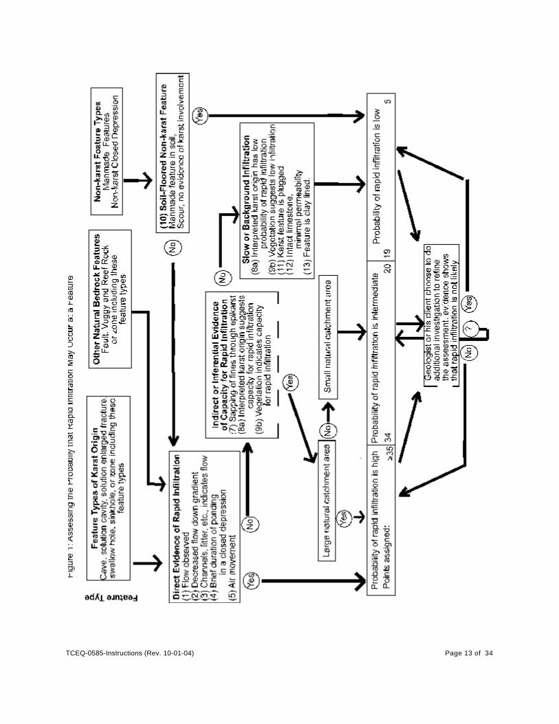
probability of occurring using the information observed at the feature (or zone) and entered in thetable. In the narrative description of each feature (or zone), describe indicators that by theirpresence or absence lead you to interpret that a feature has a rapid infiltration rate. Figure 1provides a flowchart to help the geologist make this assessment using three categories ofprobability of rapid recharge: high ($35 points), intermediate (34–20 points), and low (19–5points). In this part of the assessment, consider what the infiltration rate would be if you broughta large tank of water to the feature and released water into the feature. (This is a mind-experiment only; no physical experiment is expected.)
Soil filling in a sinkhole, solution cavity, solution-enlarged fracture, or cave does notindicate that rapid infiltration cannot occur at the feature. Long-term maintenance of a cavity ordepression is strong evidence that focused flow moves water out the drain in the floor of thedepression with sufficient velocity to move soil. The drain may be in the subsurface beneath soilor limestone rubble and connected to the surface via drainage systems in the epikarst, or it maybe exposed in the floor of the sinkhole. Soil in the floor of the cavity or sinkhole may be intemporary storage between the time it was moved into the feature and the time it will be movedthrough the drain. However, existence of a well-formed soil profile or gray or red colors in fine-grained fills are evidence that the soil has a long residence time and may be used as evidencethat the feature is relict or inactive and has a low infiltration rate.
TCEQ-0585-Instructions (Rev. 10-01-04) Page 13 of 34
TCEQ-0585-Instructions (Rev. 10-01-04) Page 14 of 34
High probability of rapid flow ($35 points) should be assigned where there is directevidence of rapid flow or reason to interpret that rapid flow occurs into the feature. Directevidence includes (1) observation of flow into the feature, (2) decreased flow downgradient fromthe feature, (3) evidence of flow into the feature (litter, elongated grass, etc.), and (4) briefduration of ponding in a closed depression. As an index against which to evaluate brief durationof ponding, unsaturated zone flow model simulations show that a conservative duration ofponding for 8 cm of water on a moderately dry clay loam soil over carbonate bedrock is 24hours. Ponding will be somewhat longer if the soil is wet or finer grained. Shorter duration ofponding indicates relatively rapid flow into the subsurface, most likely related to conduit flow.Other evidence that geologists commonly use to support their judgment that there is a highprobability of rapid recharge includes (5) air movement into or out of a cave, solution cavity, orfracture, indicating that a significant volume of underground passageway is interconnected. (6) Apositive result for karst conduit or preferential flow response from a tracer or infiltration test isalso a reason to assign high probability of rapid flow. Soil, sticks, leaves, and trash commonlyaccumulate in recharge features. Probing or excavation through these materials may be neededto determine the type and extent of the feature.
The absence of direct evidence of rapid infiltration is not sufficient to determine that afeature has a background infiltration rate because features capable of rapid recharge arecommonly intermittently active and become plugged with soil, gravel, and vegetation that may beeasily removed to reactivate the feature. Furthermore, appropriate conditions to cause rapidinfiltration may not occur during the time that the assessment is being conducted. Otherfeatures are relict, and the flowpaths leading to them have been bypassed so that they are notcritical to the current flow system. It is important that the geologist highlight inactive features thatstill retain capacity for rapid infiltration so that as surface-water flow is modified duringdevelopment these features can be adequately protected. The most commonly used indirectindicators that rapid infiltration has occurred in the past and could occur again if water orcontaminate were introduced at the surface are (7) transport of fines out of the feature, (8)interpreted feature origin, and (9) vegetation.
Correct identification of the potential for rapid recharge in partly soil-filled features ischallenging but important. Thin soils typical of the Edwards recharge zone offer limited potentialfor protection of the aquifer, and the modification of the site topography or surface-water flowduring development can further reduce the retardation function of the soil. Over geologic timegeomorphic processes work to level and grade the landscape by filling depressions withmaterials such as weathering products and dust. Maintenance of an opening or depression at acave, solution cavity, swallow hole, sinkhole, or fault is a common indicator in karst terrains thatsoil is being transported through a conduit beneath the feature. The subsurface transport offines is commonly determined by a process of elimination. That is, if the depression is notformed by surface water (scour) or by biologic processes (human, animal, or vegetative), thentransport of soil through a subsurface karst conduit is suspected and the feature should beranked as having a high or intermediate probability of rapid infiltration. In cases where theconfidence level of this process of elimination is inadequate for satisfactory BMP design, thegeologist or his client may choose to do further assessment in order to revise the feature type orprobability of rapid infiltration ranking.
Feature geometry is important in assessing the probability of rapid recharge.
TCEQ-0585-Instructions (Rev. 10-01-04) Page 15 of 34
Assessment of cave genesis (phreatic, vadose, and discharge features, for example) iscommonly used to determine the most likely role of caves in infiltration. Geologists shouldobtain and apply in-depth knowledge of cave and karst feature genesis available from manyresources. Experience with the features of Edwards caves may be of substantive help inassessment.
Vegetation is a very sensitive index of soil moisture. Geologists experienced inconducting geologic assessments carefully check the area under tall and large trees forfeatures, because a feature focusing water flow to the root zone is a common reason for thesuccessful growth and long life of the tree. Some trees can be used as clues to higher thanaverage infiltration rates; for example, persimmon is reported to be common near fractures andkarst features in some areas. Many caves have been discovered by uprooting a large shrub orcactus that was capitalizing on a favorable moisture environment in a solution cavity. Luxuriantgrasses can also be indicators of infiltration and are commonly the first indicator that can bespotted to locate a subtle but significant soil-floored sinkhole. If a depression does not drainrapidly, grasses will be killed after heavy rains and prolonged ponding, so in a closed depressionwith a drainage area, preservation of grass is an indicator of rapid infiltration rates. Othervegetative patterns; however, are indicators that discharge is focused at a seep, and thehydrologic and geologic setting of these areas may document that they have low probability ofrapid infiltration. Wetland vegetation can be used to determine that discharge or long-termponding occurs at a feature. Vegetation generally reduces infiltration to the aquifer because theroots capture water that is then lost from the soil through evapotranspiration. Evapotranspirationcan be used for aquifer protection to reduce recharge of low-quality water. However, vegetationas well as soil characteristics may be changed during development of the site. If the geologistinterprets that evapotranspiration has an important role in water balance or the ecology of afeature, this information should be noted for consideration in BMP design.
The size of the catchment area is a factor that should be considered in assessing theprobability that a feature is capable of rapid infiltration. Features that drain a catchment area$1.6 acres and, therefore, have potential to serve as a significant recharge feature should begiven a high probability ($35 points) of rapid infiltration. This assumption is based on theconcept of feedback within a karst system—that is, when a flow path carries a lot of water, theopenings that comprise that flow path are more likely to become enlarged and better connectedthrough time than the openings on a flow path that has moved smaller volumes of water.
If the geologist considers the probability that rapid infiltration can occur at a featureintermediate between high and low, the feature is given 20 to 34 points. This ranking willcommonly be given to features that have small, poorly defined catchments (<1.6 acres) and donot appear to be very active in current recharge so that their likely response to introducedcontaminant is difficult to estimate. Typically features such as isolated solution cavities,solution-enlarged fractures, and small hydrologically inactive caves on hillsides, hilltops, orplateaus will fall into this category. Intermediate rankings may be suitable for many manmadefeatures in bedrock where fractures and vugs are present, but it is difficult to determine howeffectively they could transmit fluid. The geologist or his client can choose to conduct additionalinvestigations in an attempt to better constrain the probability of rapid infiltration and revise theassessment as a result.
TCEQ-0585-Instructions (Rev. 10-01-04) Page 16 of 34
Several reasons may justify assigning a low or background probability of rapid infiltrationrate to a feature: (10) the feature did not form through karst processes, and does not focus flowinto the subsurface; (11) the karst feature is plugged by calcite cement or by compact terrarossa (red or gray clay), or a soil profile has formed in the sediment (loose humus or transportedsediment or soil indicates recent plugging and does not qualify as a reason to assign a lowprobability of rapid infiltration to a feature); (12) the feature is formed in intact limestone withminimal leakage through hairline fractures, bedding planes, and matrix porosity; (13) the featureis lined with thick, well-indurated moist clay sediment that is protected from degradation. Karstfeatures that were formed by discharge such as active or abandoned spring orifices may havelow infiltration rates because discharge may be focused by a low-permeability rock unit. Prolonged ponding should be evaluated with care, because features like sinkhole ponds areknown to be formed by temporary plugs in the sinkhole drain and may be reactivated duringconstruction activities or by modification of the site hydrology. If the feature has been highlydisturbed so that evidence of its recharge characteristics is not preserved, it cannot be rankedas having a low relative infiltration rate unless it is further investigated.
Features having low probability of rapid infiltration are given 5 to 19 points.
9. Total feature characteristic points
Add the points from Column 2B for the type of feature to the points for applicablecolumns 5A and 8B, and place the total in the column labeled total.
10. Sensitivity
Place the feature characteristic total in the appropriate box in Column 9. Features with<40 points are considered not sensitive, and those with >40 points are ranked as sensitive.
11. Catchment area
The areal extent in acres of the watershed that was directed into or toward the geologicor manmade feature under pre-development conditions. This includes the area on the projectsite as well as areas upgradient of the project site. Outlining the drainage area on a detailedcontour map may complement field evaluation of the catchment area for small areas.
12. Topography
Indicate the topographic location of a geologic or manmade feature with respect toterrain. Mark only one of the following choices:
Cliff – vertical/near-vertical cliff above 100-year floodplainHilltop – low topographic relief at top of hill or ridge crest, low-relief plateauHillside – high slope area Floodplain – on 100-year floodplain, if mapped, or as estimated by the geologist.Streambed – in a drainage, or below the ordinary high-water mark on a larger creek
B. GPS Requirements
Feature positions in latitude and longitude (degrees, minutes, and decimal seconds)should be collected and entered into the geologic assessment table. The Edwards Aquifer
TCEQ-0585-Instructions (Rev. 10-01-04) Page 17 of 34
regulations do not require the use of Global Positioning System (GPS) technology, but it isencouraged. The minimum data elements for feature location information collected by anymethod should include the following, included as an attachment to the table:
The datum in which the positional information is collected (e.g.,WGS84 NAD83, NAD27,etc.)
Method of collection (i.e., GPS [preferred], interpolation from USGS quadrangle map, etc.)Date of data collectionHorizontal accuracy assessment – TCEQ requires at minimum data collected with GPS
equipment should have a Root Mean Square (RMS) horizontal accuracy of 25meters (82 ft) or better.
Name of person(s) who made the measurement.
C. Instructions For Excavation Using Heavy Equipment
An additional step in assessing a feature in the field may be to excavate with heavyequipment. This level of investigation falls within the definition of “regulated activity” and requireswritten approval from the TCEQ prior to any excavation. This type of investigation is not requiredto complete the Geologic Assessment but may be chosen by the client in cases whereadditional assessment would be helpful for site planning, BMP design, or other activities.Excavation is sometimes used to collect enough information so that a feature can be classifiedas not sensitive. The reasons for determining that a feature is not sensitive are that it is notpermeable, does not have potential for interconnectedness between the surface and thesubsurface, and that rapid infiltration cannot occur. Requests for investigation of features usingheavy equipment (jack hammers, backhoes, etc.) must be submitted to the appropriate TCEQregional office for review prior to the anticipated start date of the investigation. Any such requestshould include the following information:
Scope of Work - A description of the manner in which the investigation will be performed.Include extent of excavation, type of equipment to be used for excavating, andmeasures proposed to protect sensitive features and streams.
Site Location - Information and maps of the site location should include a legible road mapthat is sufficient to enable the TCEQ field staff to locate, travel to, and inspect thesite.
Site Plan - Provide a site plan with a minimum scale of 1 inch = 400 feet showing the siteboundaries and existing contours at no greater than 10-foot intervals. The site planshould show the location of the features, area to be excavated, storage sites forspoils, proposed locations for temporary erosion and sedimentation controls, andthe location of nearby surface streams or other geologic features.
Permanent Pollution Abatement - Describe the proposed manner for permanent disposalof spoil material. Describe measures to stabilize the feature and surrounding areasthat will be disturbed during the investigation. Include a plan to secure the openingto the feature, if necessary.
You may be responsible for meeting other regulatory requirements in addition to thoserequired by TCEQ for such activities.
D. Features Encountered During Sewer Construction
It is common for previously unsuspected solution-enlarged fractures, cavities, and cavesto be discovered during construction of deep trenches for storm and sanitary sewer lines.Shallower trenches such as those typically constructed for utilities are more likely to be in the
TCEQ-0585-Instructions (Rev. 10-01-04) Page 18 of 34
soil profile and are less likely to encounter large openings. The Edwards Rule 213.5(b)(4)(C)(IV) extends the requirement for maintaining natural flow to features encountered duringexcavation.
The highest level of concern for the geologist is to support the engineering issuesregarding the structural integrity of the sewer pipe across the void and the structural integrity ofthe land surface. Introduction of potentially large quantities of poor quality water directly into thekarst system over a long period of time through pipe failure is a scenario with high risk of aquiferand spring contamination. The impact of the breach created by the trench in the structural beamof the cave roof should be considered. There is a possibility that the risk of roof collapse couldbe increased and geologists reports should provide enough information about the cave geometryso that appropriate BMPs can be designed.
The same questions of whether a feature is active or relict and whether it meets thecriteria in the rules to be considered sensitive apply to features encountered in trenches as tofeatures exposed at the surface. The following checklist is provided for this assessment. If anyof the features indicate that flow should be maintained, then the engineering solution shouldprovide a mechanism for maintaining flow.
Table 4. Classification of features encountered during sewer constructionCharacteristics that indicate feature flowcharacteristics should be maintained
Characteristics that indicate that thefeature is not a major component of theflow system, fill acceptable
Flowing or ponded water observed Compact red or gray clay completely fillsvoids
Deposits of organic material, leaves, darksoil, twigs, trash
Dry and dusty appearance
Evidence of flow, layered sediment on thecavity floor
Localized cave, opening narrows to smallaperture down gradient
Close to a spring discharge point Injection or tracer test showedbackground values of injectivity or no flowto spring
Active Dripstone or Flowstone
Disturbed soils that backfill pipeline trenches can serve as preferential pathways forcontaminant migration. Trench design should limit the potential for low-quality surface water toaccess the subsurface through the trench backfill.
IV. Glossary
Aperture Size of the opening into a fracture, cave, or solution cavity. Aperture can be measuredwith a tape or ruler for large openings or with a feeler gauge for small spaces.
BMP Best management practices - schedule of activities, prohibitions of practices,maintenance procedures, and other management practices to prevent or reduce thepollution of water in the State. BMPs also include treatment requirements, operatingprocedures, and practices to control site runoff, spillage or leaks, sludge or wastedisposal, or drainage from raw material storage. BMPs are those measures that arereasonable and necessary to protect groundwater and surface water quality, as provided
TCEQ-0585-Instructions (Rev. 10-01-04) Page 19 of 34
in technical guidance prepared by the executive director or other BMPs that aretechnically justified based upon studies and other information that are generally reliedupon by professionals in the environmental protection field and are supported by existingor proposed performance monitoring studies. These include, but are not limited to U.S.Environmental Protection Agency, American Society of Civil Engineers, and WaterEnvironment Research Foundation guidance.
Breakdown Accumulation of angular clasts or blocks generated by cave collapse. Breakdownis usually permeable and flow may occur within breakdown even if the overlying cavefloor is dry.
Catchment area The area that gathers water originating as precipitation and contributes to afeature. Traditionally this includes all the area bounded by a drainage divide ortopographic break in slope between one basin and another. The catchment area ofsome hillside or plateau karst features is diffuse; however, it can be operationally definedby multiplying the width of the area that could plausibly drain to the feature times thedistance to the top of the hill, plus any area in the downslope direction that drains to thefeature. Channels are not required to define the catchment area. Outlining the drainagearea on a 2-foot or other detailed contour map is recommended. Offsite areas must beincluded in the calculation of catchment area.
Cave A natural underground open space formed by dissolution of limestone that is large enoughfor an average-sized person to enter. Note that caves are commonly partly filled bybreakdown, loose rocks, debris, or soil; assessment requires sufficient investigation todefine the dimensions of the feature defined by in-place bedrock. Excavation or trenchingcan open a formerly inaccessible space to permit entry; this possibility should beconsidered when describing karst features.
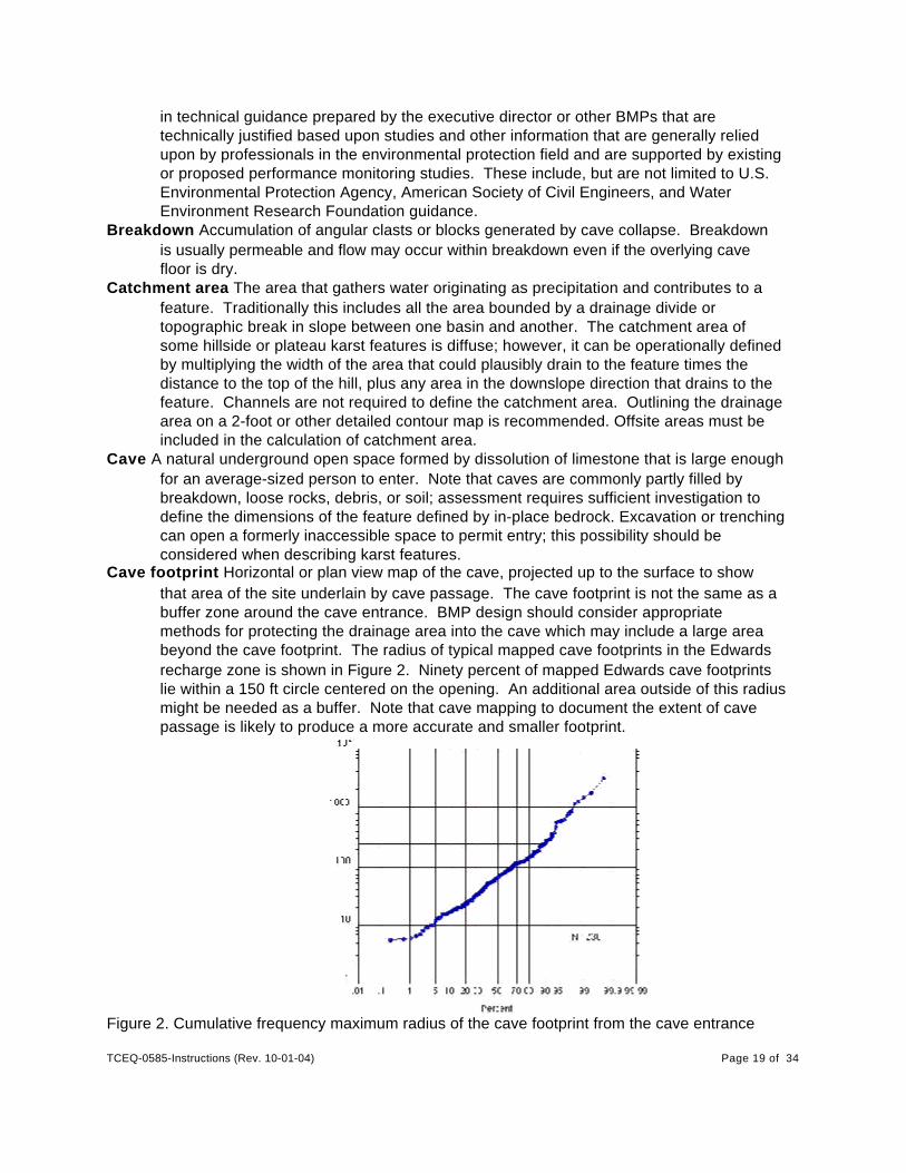
Cave footprint Horizontal or plan view map of the cave, projected up to the surface to showthat area of the site underlain by cave passage. The cave footprint is not the same as abuffer zone around the cave entrance. BMP design should consider appropriatemethods for protecting the drainage area into the cave which may include a large areabeyond the cave footprint. The radius of typical mapped cave footprints in the Edwardsrecharge zone is shown in Figure 2. Ninety percent of mapped Edwards cave footprintslie within a 150 ft circle centered on the opening. An additional area outside of this radiusmight be needed as a buffer. Note that cave mapping to document the extent of cavepassage is likely to produce a more accurate and smaller footprint.
Figure 2. Cumulative frequency maximum radius of the cave footprint from the cave entrance
TCEQ-0585-Instructions (Rev. 10-01-04) Page 20 of 34
measured from 236 mapped caves in the Edwards recharge zone in the TexasSpeleological Survey files.
Discharge feature Spring or seep where water is discharged from a local or regionalgroundwater system that may have an associated system of caves or solution cavities.
Dripstone Calcium carbonate or other minerals that precipitate on cave roofs or wall and cavefloors from dripping water, stalactites, soda straws, etc.
Edwards Aquifer That portion of an arcuate belt of porous, waterbearing, predominantlycarbonate rocks known as the Edwards (Balcones Fault Zone) Aquifer trending fromwest to east to northeast in Kinney, Uvalde, Medina, Bexar, Comal, Hays, Travis, andWilliamson Counties; and composed of the Salmon Peak Limestone, McKnightFormation, West Nueces Formation, Devil's River Limestone, Person Formation, KainerFormation, Edwards Group, and Georgetown Formation. The permeable aquifer unitsgenerally overlie the less-permeable Glen Rose Formation to the south, overlie the less-permeable Comanche Peak and Walnut formations north of the Colorado River, andunderlie the less-permeable Del Rio Clay regionally.
Epikarst Upper part of the bedrock at the surface or beneath the soil that is characterized byincreased fracturing and enhanced limestone dissolution. The epikarst is a zone ofsignificant water storage and transport. Synonym for subcutaneous zone.
Fault Fracture along which there has been displacement of one side of the fracture relative tothe other side. It is common in the Balcones fault zone for the displacement to occuracross a fault zone composed of a number of faults and fractures. Some of the exposedBalcones faults are filled with cement and breccia and pulverized clay and limestone(fault gouge). Other fault zones are poorly exposed and are recognized by juxtapositionof different stratigraphic intervals, by topographic or vegetation patterns that suggest astructure beneath the soil (lineament), and by unusually abundant and strongly orientedfractures or fracture zones in exposed bedrock.
Feature density A measurement on a transect that extends one or more times across thefeature in a direction that will adequately sample the number of observed features.Represent as a feature density as a fraction in the units of number of features/footmeasured.
Features Geologic or manmade features on the recharge zone or transition zone with asuperficial appearance that suggests that a potential for hydraulic interconnectednessbetween the surface and the Edwards Aquifer exists, and rapid infiltration to thesubsurface may occur. These features include but are not limited to closeddepressions, sinkholes, caves, faults, fractures, bedding plane surfaces, interconnectedvugs, reef deposits, wells, borings, and excavations.
Flowstone Calcium carbonate or other minerals that precipitate on cave walls and cave floorsfrom flowing water.
Geologic assessment A report prepared by a geologist describing site-specific geology. Thefocus of the geologic assessment is identification and evaluation of geologic andmanmade features to determine which features are sensitive.
Geologist A person who has received a baccalaureate or post-graduate degree in the naturalscience of geology from an accredited university and has training and experience ingroundwater hydrology and related fields, or has demonstrated such qualifications byregistration or licensing by a state, professional certification, or completion of accrediteduniversity programs that enable that individual to make sound professional judgmentsregarding the identification of sensitive features located in the recharge zone or transition

TCEQ-0585-Instructions (Rev. 10-01-04) Page 21 of 34
zone. After September 1, 2003, geologists conducting assessments are required to belicensed according to the Texas Geoscience Practice Act..
Global Positioning System (GPS) A low- to- moderate-cost portable device that is used todetermine location in latitude and longitude or other coordinate system.
Humus Dark organic material in a soil typically includes humus.Infilling in features Note the conditions when you visit the feature – does it appear to be in
natural condition or has it been disrupted by activities on the site? Washed-in or remnantmaterial in the feature that gives evidence of the dynamics of the feature with respect tosurface water and recharge flow. Some features lack filling and can be described asbedrock floored. Coarse material that has been somewhat rounded by transport isdescribed as cobbles or gravel. Nontransported slabs of rock collapsed into a karstfeature is called breakdown. Typical loose or soft mud or soil infilling can also includeorganics, leaves, sticks, and humus and has gray to dark brown colors. Fine-grainedcompacted clay-rich sediment is distinguished from the loose and soft sediment by redor gray colors or by incipient soil profile development. Reddish clay-rich insoluble residuewithin karst can be described as terra rossa. Vegetation is a common component ofinfilling and may provide evidence of the hydrologic significance of the feature. Dripstoneand flowstone are commonly formed in caves and can be either active or relict. Calcite orother cements can partly or completely fill vugs and fractures. Many other types ofinfillings may be observed and should be briefly described in the narrative.
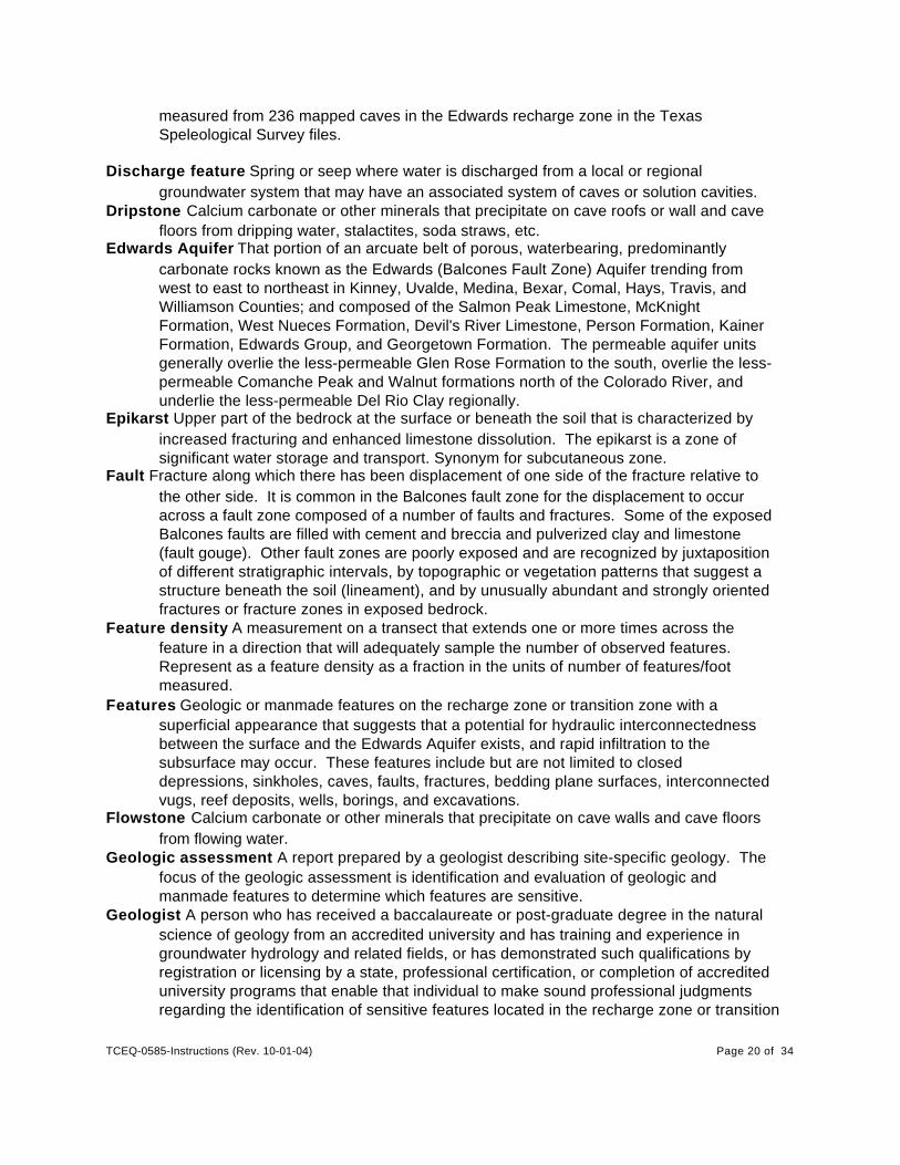
Infiltration Movement of water into the pores and openings in soil and rock. Losses from aponded water body can be by evaporation or by infiltration. The infiltration rate ismeasured in depth of water absorbed into the rock or soil per unit time under specifiedconditions. Modeled infiltration rates shown in Figure 3 for background conditions providecontext for describing rapid infiltration.
TCEQ-0585-Instructions (Rev. 10-01-04) Page 22 of 34
Figure 3. Modeling results showing time in days for ponded water of various initial headsto drain through soil under background conditions. Faster drainage qualifies as rapidrelative to background. Hydrus-ID code (Simunek and others, 1998) on 5 m of clay loam(hydraulic conductivity 6cm/day). Dry conditions used matric potential of -1000 cm andmoist conditions used -100 cm.
Karren Superficial (millimeter to meter depth) sculpture resulting from bedrock solution by directrainfall, sheet wash, channel flow, and percolation under mantle to form channels,furrows, and pits separated by ridges or pinnacles. Karren, because of their superficialorigin, are not sensitive features unless they are hydraulically connected to a feature thatsuggests connection to the subsurface or rapid infiltration.
Karst features Geomorphic, topographic, and hydrologic features formed by solution oflimestone by water. Caves, solution cavities, sinkholes, swallow holes, solution-enlargedfractures are common types of karst features; many more can be found in a textbook orglossary of karst terms.
Manmade feature in bedrock Water wells, sanitary sewer lines, storm sewer lines, trenches,quarries, and other cultural features that intersect bedrock and can potentially increasethe rate of recharge to the subsurface.
Non-karst closed depression A natural or non-natural topographic depression that is notformed by karst processes and is not bedrock floored. Features larger than 6 feet in atleast one direction and with 6 inches or more of topographic relief should be listed in the
TCEQ-0585-Instructions (Rev. 10-01-04) Page 23 of 34
table. Examples of non-karst closed depressions include scoured pools in drainages,animal wallows, large animal burrows, large pits created by clearing tree stumps,dammed tanks, or other agricultural constructions that are soil floored and do not modifythe topography on top of bedrock. Care must be taken to determine that the feature wasnot a karst feature that has been subsequently modified by human or animal activities ora scour that overlies a swallet. The reasons for determination that the feature is non-karst should be noted in the narrative description of site geology.
Ordinary high-water mark On non-tidal rivers the line on the shore established by thefluctuations of water and indicated by physical characteristics such as a clear, naturalline impressed on the bank; shelving; changes in the character of soil; destruction ofterrestrial vegetation; the presence of litter and debris; or other appropriate means thatconsider the characteristics of the surrounding areas.
Phreatic cave Cave initiated and developed by dissolution under conditions where all voids arewater filled, usually below the water table. Progressive abandonment of phreatic cavesusually occurs as erosion lowers valley floors and parts of the flooded system aredrained. Phreatic caves can be recognized by evidence of dissolution not stronglycontrolled by gradient, including “blind” pockets on walls and ceilings. The mostcommon phreatic passage form is a tube; however, modification of this passage shapecommonly occurs by collapse when the void is dewatered and by reworking in thevadose zone.
Recharge zone Generally, that area where the stratigraphic units constituting the EdwardsAquifer crop out, including the outcrops of other geologic formations in proximity to theEdwards Aquifer, where caves, sinkholes, faults, fractures, or other permeable featureswould create a potential for recharge of surface waters into the Edwards Aquifer. Therecharge zone is identified as that area designated as such on official maps located inthe appropriate regional office and groundwater conservation districts.
Reef limestone Accumulations of the shells and shell fragments of rudists are characteristic ofsome parts of the Edwards Group. These rocks may be porous because space ispreserved between coarse shell fragments or because rudist shell material hasdissolved, forming large pores. The large and interconnected pores of reef limestoneprovide higher permeability than tight limestone; however, matrix permeability is probablyan order of magnitude lower than fracture and karst permeability and, therefore, in mostcases would be considered part of the background, non-focused recharge.
Sensitive feature Permeable geologic or manmade feature located on the recharge zone ortransition zone where a potential for hydraulic interconnectedness between the surfaceand the Edwards Aquifer exists, and rapid infiltration to the subsurface may occur.Geologists doing the assessment are not asked to express a high degree of certaintythat these conditions are met in order to rank features as sensitive.
Setback A buffer area widely used for protection of karst features. Setback usually implies thatland use is restricted to activities that are protective of water quality and water quantity,and/or biologic or cultural aspects of the feature. Setback size and extent should bethoughtfully designed to accomplish a specified objective over a stated timeframe.
Significant recharge feature A karst feature with a well-defined surface opening (such as acave) or a sinkhole (without a surface opening) that has a catchment area greater than1.6 acres.
Sinkhole A shallow, broad topographic depression formed in response to karst processes.Sinkholes are pragmatically defined as features greater than 6 feet in diameter havingmore than 6 inches of topographic relief. Smaller karst features can be described as
TCEQ-0585-Instructions (Rev. 10-01-04) Page 24 of 34
solution cavities. Sinkholes are usually circular or funnel shaped and sometimes haveexposed rimrock at the perimeter. It is common for sinkholes to have other karstopenings (caves, solution cavities, or solution-enlarged fractures) in the floor. Sinkholeimplies that processes including collapse, subsidence, and soil sapping over geologictime have caused the land surface to sink below the surrounding area. Sinkholes canhave very subtle topographic expressions, so awareness of soil and vegetationcharacteristics can help the geologist locate them. For well-developed sinkholes, thesinkhole geomorphology should be mapped to provide detail needed to support BMPdesign, including the drainage area, break in slope at the edge of the bowl, bowl volume,drain location(s), drain type and size.
Site The entire area included within the legal boundaries of the property described in theapplication. Regulated activities on a site that is located partially on the recharge zoneand transition zone, where the natural drainage in the transition zone flows back to therecharge zone, will be treated as if the entire site is located on the recharge zone.
Soil profile Sediments that have been retained at the land surface will develop a soil profile thatcan be used to roughly estimate the age of the land surface. Soil profiles in the Edwardsrecharge zone typically have 6 to 18 inches of brownish-red or brownish-gray, granular tofinely blocky soil underlain by redder clayey soil with a distinctly blocky fabric (pedstructure) characteristic of soils. A fill without horizonation or without a well-formedblocky structure probably has not formed a soil profile and may be young.
Solution Cavity A natural cavity or depression formed as a result of dissolution of limestone.This category is designed to capture features that are not large enough for a normal-sized person to enter but appear to be part of a system of interconnected voids thatconnect the surface with the subsurface. The size and geometry of the feature isdefined by in-place bedrock; fill must be probed or excavated to determine the size of thefeature. If cavity size appears to increase at depth, this observation should be used toclassify the feature as a solution cavity or cave, depending on the inferred maximumsize. Note that cavities include areas where dissolution has increased the opening sizeand permeability along bedding planes as well as fractures. Features that the geologistinterprets as limited to the surface and soil zone (karren, weathering textures, andfeatures formed on loose blocks) are not reported as solution cavities.
Solution-enlarged fracture(s) Fractures that show evidence of being locally enlarged bydissolution of limestone. Solution enlargement can be recognized by mismatchedfracture surface shapes on measurable (larger than hairline) openings.
Swallet or swallow hole A focused recharge feature in an intermittent drainage or stream inkarst terrain. Some swallow holes have a surface expression, for example, a caveopening or formation of a whirlpool in the stream at high flow. The general case is thatfine soil and sediment as well as gravel are deposited over the bedrock feature duringfalling stages of flow thereby intermittently or frequently obscure it. During the geologicassessment, care must be taken to investigate the possibility that these highly sensitivefeatures may be present in drainageways. The best method is to field test for infiltrationor gauge the stream when it is flowing. Observation of rapid infiltration of pooled water atrates higher than background can help identify buried swallets. Indicators of the presenceof karst features, for example, dipping or fractured bedrock indicating collapse can helpto identify these sensitive features when they are obscured by gravel and sediments.
Terra rossa Residual red soil of some karst areas. In the Edwards recharge zone it is generallyconsidered to be a relict soil or old insoluble residue.
Transition zone That area where geologic formations crop out in proximity to and south and
TCEQ-0585-Instructions (Rev. 10-01-04) Page 25 of 34
southeast of the recharge zone and where faults, fractures, and other geologic featurespresent a possible avenue for recharge of surface water to the Edwards Aquifer,including portions of the Del Rio Clay, Buda Limestone, Eagle Ford Group, Austin Chalk,Pecan Gap Chalk, and Anacacho Limestone. The transition zone is identified as thatarea designated as such on official maps located in the appropriate regional office andgroundwater conservation districts.
Trend Direction or bearing of the outcrop of structural features such as faults, fractures, oraligned karst features. Subtle features such as topographic and vegetation alignment candefine a lineament and indicate a trend.
Vadose cave A cave that underwent most of its development above the water table. Within thevadose zone, drainage is free-flowing under gravity, and cave passages therefore haveair above water. Characteristics are uneroded ceilings and continuous downhillgradients except for short perched sumps. The main passage forms are canyons withmeanders and potholes, keyholes, and cylindrical shafts. Older higher passages havebeen abandoned by groundwater except in times of extreme aquifer recharge.
Vug Small cavity in limestone, smaller than a solution cavity but larger than normal intergranularpores (<1 foot >1/4 inch). Vugs in Edwards Limestone commonly occur where burrowfillings have preferentially weathered, creating “sponge work.” This effect is bestdeveloped at the near surface; at depth the burrow-filling calcite and dolomite arepreserved, although they may be highly leached and permeable. Vugs rimmed withcalcite crystals (dog-tooth spar) are common indicators that gypsum or anhydritenodules have been dissolved. Large pores of vuggy limestone, if interconnected, providehigher permeability than limestone with smaller pores; however, matrix permeability isprobably an order of magnitude lower than fracture and karst permeability and thereforein most cases would be considered part of the background non-focused recharge.Preservation of outcropping boulders of vuggy limestone may be evidence that flow hasnot been focused through these rocks in the epikarst. The area should be examined forevidence that the vuggy rock has preferentially formed karst features.
Zone Any type of karst feature that occurs along a trend or in a cluster can be described as azone. Aligned or clustered features are more likely to be an indicator of an integrated flowsystem at depth than an isolated feature. Alignment is expected in areas where conduitflow is strongly influenced by structurally controlled fractures. Fracture control favorsconnection between the surface and the subsurface and integrates subsurface flowpathsto provide rapid flowpaths to the aquifer and to discharge points. Fracture zones are welldeveloped adjacent to faults and may be more permeable than the fault plane itself. Zones of clustered or aligned features can be indicated by subtle evidence such asvegetation, changes in soil properties, and subtle topographic changes.
V. Citations For Sources of Further Information
Barrett, M. E., 1999, Complying with the Edwards Aquifer Rules: Technical Guidance on BestManagement Practices: TCEQ, Field Operations Divisions, RG-348.
BMP design guidance for Edwards recharge zone
Center for Cave and Karst Studies, Western Kentucky University, Bowling Green.http://caveandkarst.wku.edu/index.html
TCEQ-0585-Instructions (Rev. 10-01-04) Page 26 of 34
Karst and groundwater related coursework and seminars, links
Clark, A. C., 2000, Vulnerability of groundwater to contamination, Edwards aquifer recharge zone,Bexar County, TX, 1998, USGS Water-Resources Investigations Report 00-4149.
Detailed regional vulnerability mapping using air photo interpretation and consideration ofhydrogeologic unit, faults, sinkholes and caves, and slope and soil characteristics.
Collins, E. W., 2000, Geologic map of the New Braunfels 30" x 60" quadrangle: The University ofTexas at Austin, Bureau of Economic Geology Miscellaneous Map 39, 1:100,000.
Geologic map of Edwards outcrop, western Hays County to Medina Lake.
Eckhardt, G. A., 2000, The Edwards aquifer homepage:
http://www.edwardsaquifer.net/.
Recently updated review of some of the issues and research relevant to understanding the Edwardsaquifer.
Elliott, W. R., Veni, George, 1994, The caves and karst of Texas: a guidebook for the 1994convention of the National Speleological Society with emphasis on the southwesternEdwards Plateau.
Overview of major Texas caves, including Edwards caves
Field, M. S.,1999, A lexicon of cave and karst terminology with special reference to environmentalkarst hydrology: U.S. Environmental Protection Agency National Center for EnvironmentalAssessment Office of Research and Development, EPA/600/R-99/006, 201 p. PDF PortableDocument Format available from http://www.karstwaters.org/files/glossary.pdf.
Extensive and updated (1998) glossary of karst terms.
Ford, D. C., and Williams, P. W., 1989,
Karst geomorphology and hydrology: Unwin Hyman, London, 601 p.
Widely cited textbook containing chapters on karst landforms and karst hydrology with abrief overview of construction and pollution issues related to karst.
Ging, P. B., Judd, L. J., Wynn, K. H., 1997, Water-quality assessment of south-central Texas;occurrence and distribution of volatile organic compounds in surface water and groundwater, 1983-94, and implications for future monitoring: U.S. Geological Survey, Water-Resources Investigations WRI 97-4028, 20 p.
Water quality data, San Antonio segment
Hanson, J. A., and Small, T. A., 1995, Geologic framework and hydrogeologic characteristics ofthe Edwards Aquifer outcrop, Hays County, Texas: U.S. Geological Survey, Water-Resources Investigations WRI 95-4265, p. 10 (1 sheet).
Geologic mapping of hydrogeologic members of the Edwards Group, Hays County.
Jackson, J. A., ed., 1997, Glossary of geology (4th ed.): Alexandria, Va., American GeologicalInstitute.
TCEQ-0585-Instructions (Rev. 10-01-04) Page 27 of 34
General purpose geology glossary
Klimchouk, A. B., Ford, D. C., Palmer, A. N., Dreybrodt, Wolfgang, eds., 2000, Speleogenesis;evolution of karst aquifers: Huntsville, Ala., National Speleological Society, 527 p.
Diverse collection of recent technical papers on karst.
Mahler, B. J., Lynch, L., Bennett, P. C., 1999, Mobile sediment in an urbanizing karst aquifer;implications for contaminant transport, Environmental Geology: v. 39, no. 1, p. 25-38.
Research on mechanisms of contaminant transport, Barton Springs segment
Menard, J. A., 1995, Bibliography of the Edwards Aquifer, Texas, through 1993: U.S. GeologicalSurvey, Open-File Report OF 95-0336, p. 75.
Bibliography compiled as an initial step of the NWQA study, 1022 citations to 1993.
Palmer, A. N., 1991, Origin and morphology of limestone caves: Geological Society of AmericaBulletin, v. 103, no. 1, p. 1-21.
Basic review paper on karst processes
Simunek, J., M. Sejna, and M. T. van Genuchten, 1998, The Hydrus-1D Software Package forSimulating the One-Dimensional Movement of Water, Heat, and Multiple Solutes inVariably-Saturated Media, Users Manual, Version 2.0, U.S. Salinity Laboratory,Agricultural Research Service, 178 p.
Code used for calculation of infiltration rates
Small, T. A., and Hanson, J. A., 1994, Geologic framework and hydrogeologic characteristics ofthe Edwards Aquifer outcrop, Comal County, Texas: U.S. Geological Survey, Water-Resources Investigations WRI 94-4117, p. 10 (1 sheet).
Geologic mapping of hydrogeologic members of the Edwards Group, Comal County.
Small, T. A., and Hanson, J. A., Hauwert, N. M.,1996, Geologic framework and hydrogeologiccharacteristics of the Edwards Aquifer outcrop (Barton Springs segment), northeasternHays and southwestern Travis counties, Texas: U.S. Geological Survey, Water-Resources Investigations WRI 96-4306, p. 15 (1 sheet).
Geologic mapping of hydrogeologic members of the Edwards Group, Travis/HaysCounty.
Small, T. A., and Lambert, R. B., 1998, Geologic framework and hydrogeologic characteristics ofthe outcrops of the Edwards and Trinity aquifers, Medina Lake area, Texas: U.S.Geological Survey, Water-Resources Investigations WRI 97-4290, p. 17 (1 sheet).
Geologic mapping of hydrogeologic members of the Edwards Group, part of MedinaCounty.
Stein, W. G., and Ozuna, George, 1995, Geologic framework and hydrogeologic characteristicsof the Edwards Aquifer recharge zone, Bexar County, Texas: U.S. Geological Survey,Water-Resources Investigations WRI 95-4030, p. 8 (1 sheet).
Geologic mapping of hydrogeologic members of the Edwards Group, Bexar County.
Texas Speleological Survey http://www.utexas.edu/depts/tnhc/.www/tss/
The Texas Speleological Survey is a non-profit corporation with a mission to collect,

TCEQ-0585-Instructions (Rev. 10-01-04) Page 28 of 34
organize, and maintain information on Texas caves and karst.
U.S. Department of Agriculture, Soil Conservation Service, Engineering Division, 1975, Urbanhydrology for small watersheds: Technical Release no. 55, variably paginated.
Methodologies and tables for calculation of impacts of land use on surface waterconcentration, travel time, lag, peak discharge.
U.S. Fish and Wildlife Service, 2000, Karst feature survey protocols, draft: U.S. Fish and WildlifeService field office, Austin, Texas.
USF&WS instructions for cave surveys.
U.S. Fish and Wildlife Service, not dated, Determinations and take guidance: U.S. Fish andWildlife Service field office, Austin, Texas.
Geographic regions of the Edwards recharge zone and USF&WS recommendations fortypes of surveys.
Veni, George, 1988, The caves of Bexar County (2nd ed.),: The University of Texas at Austin,Texas Memorial Museum Speleological Monographs 2, 300 p.
Index and map to caves from the Texas Speleological Survey files at date of publication.
Veni and Associates, 1992, Geologic controls on cave development and the distribution of cavefauna in the Austin, Texas, region. Prepared for the U.S. Fish and Wildlife Service.Austin, Texas.
Veni, George,1994, Geologic controls on cave development and the distribution of endemic cavefauna in the San Antonio, Texas, region: Section 6, report prepared for the Texas Parksand Wildlife Department and the U.S. Fish and Wildlife Service, 99 p.
Veni, George, 1999, A geomorphological strategy for conducting environmental impactassessments in karst areas: Geomorphology, v. 31, Issues 1-4, December 1999, p. 151-180.
Outline of a detailed karst assessment methodology developed at Camp Bullis andelsewhere in the Edwards recharge zone.
White, W.B, 1988, Geomorphology and hydrology of karst terrains: Oxford University Press, 464p.
Karst textbook

TCEQ-0585-Instructions (Rev. 10-01-04) Page 29 of 34
Figure 4. EAPP - Solution Cavity Form on the following pages.

TCEQ-0585-Instructions (Rev. 10-01-04)
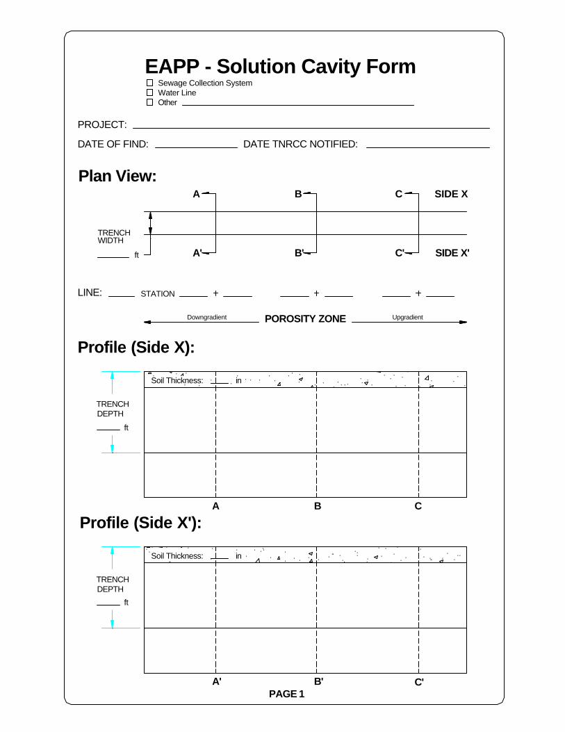
TCEQ-0585-Instructions (Rev. 10-01-04) Page 31 of 34
C
C'
Sewage Collection SystemWater LineOther
BA
Soil Thickness:
Profile (Side X'):
PAGE 1A'
in
B'
Downgradient
EAPP - Solution Cavity Form
Soil Thickness:
Profile (Side X):
TRENCHDEPTH
ft
ft
WIDTHTRENCH
STATIONLINE:
PROJECT:
Plan View:
POROSITY ZONE
in
A' B'
DATE OF FIND:
A B
C
C'
SIDE X'
Upgradient
SIDE X
ft
TRENCHDEPTH
DATE TNRCC NOTIFIED:

TCEQ-0585-Instructions (Rev. 10-01-04)

TCEQ-0585-Instructions (Rev. 10-01-04) Page 33 of 34Signature of Geologist
PAGE 2
Date
Cross-Section View:
Sewage Collection System
TNRCC - EAPPSolution Cavity Form
Notes:
·Include dimensioning·Include illustrative pictures for complex features·Attach additional pages if necessary.·Identify case of feature (EAGD 96.004)
Printed Name of Geologist
SensitivityCaseFeatureStationLine
Section A-A' Section B-B' Section C-C'
Notes:

TCEQ-0585-Instructions (Rev. 10-01-04)