Embed Size (px)
Citation preview

Instrument Docking Station Start-up Guide
for the DS2 Docking Station
Start-up Software Installation
Part Number: 17141623 Release Date: December 20, 2013 Version No.: 7
DS2 Docking Station
ii INDUSTRIAL SCIENTIFIC
DS2 Docking Station is a trademark of Industrial Scientific Corporation. iNet Instrument Network is a trademark of Industrial Scientific Corporation. GasBadge® is a registered trademark of Industrial Scientific Corporation. All other trademarks and registered trademarks are the property of their respective owners.
Industrial Scientific Corporation Phone: 412-788-4353 Headquarters Toll Free: 1-800-DETECTS (338-3287) 1001 Oakdale Road Fax: 412-788-8353 Oakdale, PA 15071-1500 Service: 1-888-788-4353 USA Web: www.indsci.com
Although every effort is made to ensure accuracy, the specifications of this product and the content herein are subject to change without notice.
Industrial Scientific Corporation. Oakdale, PA USA Shanghai, China Arras, France © 2012, 2013 Industrial Scientific Corporation All rights reserved. Published 2013
DS2 Docking Station
INDUSTRIAL SCIENTIFIC iii
Warnings and Cautionary Statements
WARNING: Failure to perform certain procedures or note certain conditions may impair the performance of this product. For maximum safety and optimal performance, please read and follow the procedures and conditions listed below.
Use of this product in areas where it may be subject to large amounts of electromagnetic interference may affect the reliable operation of this device and should be avoided.
Sources of large amounts of interference could be and are not limited to:
o Operation near high radio frequency fields (near 2-way radio transmission antennas where the RF fields may greatly exceed 10 V/M, etc.).
o AC Power Mains that may have excessive power surges / spikes / transients (from large AC motors operating heavy loads which may induce voltage sags and, etc.).
NOTE: This product has been tested to, and passes all EMC requirements to EN 61326:1998 Electrical Equipment for Measurement, Control and Laboratory Use for Type 2 (Industrial) Apparatus, as well as FCC Part 15, Class A emissions levels when installed to the requirements outlined within this manual. Mandatory compliance to these standards help to ensure controlled, reliable operation of this device when exposed to typical levels of electromagnetic interference as well as ensuring that this device is not source of emissions that might interfere with other equipment installed nearby.
NOTE: Per 30 CFR 75.320(b), the DS2 Docking Station tests for oxygen deficiency of MSHA approved oxygen detectors compatible with the DS2 Docking Station that can detect 19.5 percent oxygen with an accuracy of ±0.5 percent.
NOTE: Per 30 CFR 22.7(d)(2)(i), the acceptable limit during calibration and bump testing with 2.5% methane must be 10% for MSHA approved instruments using Industrial Scientific certified calibration gas.
NOTE: The DS2 has an internal pump that controls the flow of gas being delivered to the system. As a result of the internal pump, a demand flow regulator must be used in conjunction with this calibration and bump test station.

DS2 Docking Station Table of Contents
INDUSTRIAL SCIENTIFIC v
Table of Contents ABOUT THIS MANUAL............................................................................................................................................ 1
1.1. DOCUMENT OVERVIEW ............................................................................................................................... 1 1.2. DOCUMENT CONVENTIONS ......................................................................................................................... 2
INTRODUCTION TO THE DS2 DOCKING STATION ........................................................................................ 3
2.1. OVERVIEW .................................................................................................................................................. 3 2.2. FEATURES ................................................................................................................................................... 4 2.3. COMPONENTS OF THE DS2 DOCKING STATION NETWORK .......................................................................... 4
2.3.2. Docking Station Server Admin Console (DSSAC) Overview ................................................................. 5 2.3.3. Instrument Docking Station (IDS) Overview ......................................................................................... 6
2.4. REQUIRED NETWORK CONNECTIONS .......................................................................................................... 7
GETTING STARTED ................................................................................................................................................. 9
3.1. INTRODUCTION ............................................................................................................................................ 9 3.2. REQUIREMENTS FOR SOFTWARE INSTALLATION ....................................................................................... 10
3.2.1. Server Requirements ............................................................................................................................ 10 3.2.2. PC Requirements ................................................................................................................................. 12 3.2.3. Running DSSAC v8.6 and higher on a machine that is to run on FDCC Settings. .............................. 12 3.2.4. Additional Requirements and Warnings .............................................................................................. 13
3.3. INSTALLING MICROSOFT INTERNET INFORMATION SERVICES (IIS) ........................................................... 15 AND MICROSOFT MESSAGE QUEUING (MSMQ) ...................................................................................................... 15
3.3.1. Overview .............................................................................................................................................. 15 3.3.3. Installing IIS and MSMQ on Windows 2000 Professional and Windows XP Professional ................. 15 3.3.4. Installing IIS and MSMQ on Windows 2000 Standard Server and Windows 2003 Server Web Edition 20
3.3.5. INSTALLING IIS AND MSMQ ON WINDOWS VISTA, WINDOWS 7, WINDOWS 8, WINDOWS 2008 SERVER
AND WINDOWS 2012 SERVER .................................................................................................................................. 25 3.3.6. Installing IIS and MSMQ on Windows 2008 ....................................................................................... 29 3.3.7. Installing IIS and MSMQ on Windows 7 ............................................................................................. 34
3.4. INSTALLING THE DOCKING STATION SERVER (DSS) SOFTWARE............................................................... 36 3.5. LOADING THE INSTALLER SOFTWARE ....................................................................................................... 36 3.6. INSTALLATION WIZARD FOR DSS ............................................................................................................. 39 3.7. DATABASE PREPARATION OPTIONS FOR FIRST TIME INSTALLATIONS ....................................................... 42
3.7.1. Overview .............................................................................................................................................. 42 3.7.2a. Install SQL Server 2005 Express Edition and a New DSS Database on This Machine ....................... 45 3.7.2b. Install New DSS Database to an Existing SQL Server/SQL Server 2005 Express Edition on This Machine 45 3.7.2c. Attach to An Existing DSS Database Available on My Network .......................................................... 47
3.8. CONTINUING INSTALLATION (OR INSTALLATION AFTER UNINSTALLING A PREVIOUS VERSION) .............. 48 3.8.1a. Use SQL Server/SQL Server 2005 Express Edition on this Machine and Connect to the Existing DSS Database ............................................................................................................................................................ 50 3.8.1b. Attach to an Existing DSS Database Available on My Network .......................................................... 51
3.9. SELECTING THE DATABASE OPTION .......................................................................................................... 52 3.9.1a. Install SQL Server 2005 Express Edition on This Machine and Use Existing DSS Database ............. 53 3.9.1b. Attach to an Existing DSS Database Available on My Network .......................................................... 54
3.10. INET CONSIDERATIONS ............................................................................................................................. 56 3.11. INSTALLING THE DS2 DOCKING STATION SERVER ADMIN CONSOLE (DSSAC) SOFTWARE ..................... 59 3.12. THE DOCKING STATION CONFIGURATOR .................................................................................................. 60
3.12.1. Installing the Docking Station Configurator Software ........................................................................ 60 3.12.2. Running the Docking Station Configurator Software .......................................................................... 61
3.13. ASSIGNING A STATIC IP ADDRESS TO A SEVER OR PC .............................................................................. 62 3.14. APPLYING STATIC ADDRESSING TO V1.4 OR HIGHER IDS ........................................................................ 64 3.15. DISABLING THE DS2 BROADCASTER ......................................................................................................... 67 3.16. CONFIGURING THE FIREWALL ................................................................................................................... 68
Table of Contents DS2 Docking Station
vi INDUSTRIAL SCIENTIFIC
3.16.1. Windows XP Firewall ............................................................................................................................ 68 3.16.2. Windows Firewall Settings for SQL Server ............................................................................................ 70
CONFIGURING THE DS2 ...................................................................................................................................... 77
4.1. INTRODUCTION .......................................................................................................................................... 77 4.2. INSTRUMENT DOCKING STATION DIAGRAM .............................................................................................. 77 4.3. SETTING UP AN INSTRUMENT DOCKING STATION ..................................................................................... 79 4.4. INSTRUMENT DOCKING STATION STATUS AND PROPERTIES ..................................................................... 80 4.5. REMOVING AN INSTRUMENT DOCKING STATION ....................................................................................... 87 4.6. CONFIGURING GAS CYLINDERS ................................................................................................................. 87 4.7. ADDING GAS FROM INDUSTRIAL SCIENTIFIC ............................................................................................. 91 4.8. ADDING GAS FROM A THIRD PARTY .......................................................................................................... 93 4.9. CHANGING GAS CYLINDERS ...................................................................................................................... 94 4.10. SUPPORTED SENSORS ................................................................................................................................ 96 4.11. USING IGAS ............................................................................................................................................... 97
BASIC OPERATION OF THE DS2 ...................................................................................................................... 100
5.1. INTRODUCTION ........................................................................................................................................ 100 5.2. MENU OPTIONS ....................................................................................................................................... 100 5.3. LED AND ALARM SIGNALS ..................................................................................................................... 102 5.4. FORCED BUMP TESTS .............................................................................................................................. 104 5.5. CALIBRATION .......................................................................................................................................... 105
5.5.1. Forced Calibrations ........................................................................................................................... 105 5.5.2. O2 Sensor Failures During Calibrations ........................................................................................... 106
5.6. DOWNLOAD AND CLEARING DATALOG DATA ......................................................................................... 107 5.6.1. Forced Datalog Download ................................................................................................................ 107 5.6.2. Clearing Datalog Data ...................................................................................................................... 108
5.7. IDS DIAGNOSTICS ................................................................................................................................... 108 5.8. INSTRUMENT DOCKING STATION OPERATING GUIDELINES ..................................................................... 110
5.8.1. General .............................................................................................................................................. 110 5.8.2. Cleaning ............................................................................................................................................. 111 5.8.3 Explanation of Symbols Used on Unit ............................................................................................... 111 5.8.4 Specifications ..................................................................................................................................... 111 5.8.5. Regulatory Notices ............................................................................................................................. 112 5.8.6. Wiring Requirements ......................................................................................................................... 112
USING CLUSTERS ................................................................................................................................................ 113
6.1. INTRODUCTION TO IDS CLUSTERS .......................................................................................................... 113 6.2. INSTRUMENT DOCKING STATION CLUSTERS ........................................................................................... 114
6.2.1. Introduction ....................................................................................................................................... 114 6.2.2. Setting up the Instrument Docking Station Hardware ....................................................................... 114 6.2.3. Configuring the Cluster ..................................................................................................................... 116 6.2.4. Removing a Cluster ............................................................................................................................ 118
EVENT SCHEDULING .......................................................................................................................................... 119
7.1. INTRODUCTION ........................................................................................................................................ 119 7.2. GLOBAL EVENTS ..................................................................................................................................... 120
7.2.1. Global Instrument Docking Station Events ........................................................................................ 120 7.2.2. Global Instrument Events .................................................................................................................. 123
7.3. SPECIAL EVENTS ..................................................................................................................................... 126 7.4. DS2 DEFAULTS FOR SCHEDULED EVENTS (V5.0 AND HIGHER) ................................................................ 129 WARRANTY ........................................................................................................................................................... 130
Limitation of Liability ...................................................................................................................................... 130 CONTACT INFORMATION ....................................................................................................................................... 134
DS2 Docking Station About This Manual
INDUSTRIAL SCIENTIFIC 1
About This Manual
Chapter
1
1.1. Document Overview
This documentation is designed to assist you in the start-up of DS2 Docking Station. For day-to-day operation and detailed information about using the features of DS2 Docking Station, please see the manuals included on the CD provided with the DS2 Docking Station.
This user guide contains the following main sections:
Chapter 2: Introduction to the DS2 Docking Station - Begin with this section to learn about the main components and an overview of the functionality of DS2 Docking Station.
Chapter 3: Getting Started - This section provides an introduction to the Docking Station Server Admin Console, the application that is used to perform administrative tasks in DS2 Docking Station. It also provides minimum server and PC requirements for proper installation and operation of the software. This section provides information on installing required operating system components, the DSS software, and the DS2 DSSAC software. An overview of the the DS2 Broadcaster is also provided, as well as how to enable and disable this feature.
Chapter 4: Configuring the DS2 – This section explains how to setup the Docking Station for operation. It includes explanations of status, properties, setup and removal, gas cylinder configuration, and connections using iGas.
Chapter 5: Basic Operation of the DS2 – This section explains the basic operation of the DS2. It includes topics such as user interface menu options, LED and alarm signals, forced bump tests, forced calibrations, downloading and clearing datalog data, IDS diagnostics, and operating guidelines.
Chapter 6: Using Clusters – This section explains the purpose of using clusters and how to configure IDS clusters.
Chapter 7: Event Scheduling – This section explains how to configure the DS2 to schedule tests, calibrations and other Docking Station events.
For information about installing DS2 Docking Station, please see Administrator’s Guide to DS2 Docking Station.
About This Manual DS2 Docking Station
2 INDUSTRIAL SCIENTIFIC
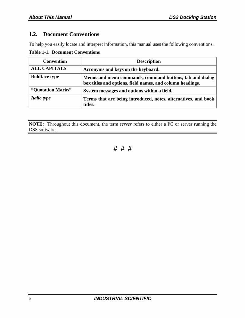
1.2. Document Conventions
To help you easily locate and interpret information, this manual uses the following conventions.
Table 1-1. Document Conventions
Convention Description
ALL CAPITALS Acronyms and keys on the keyboard.
Boldface type Menus and menu commands, command buttons, tab and dialog box titles and options, field names, and column headings.
“Quotation Marks” System messages and options within a field.
Italic type Terms that are being introduced, notes, alternatives, and book titles.
NOTE: Throughout this document, the term server refers to either a PC or server running the DSS software.

DS2 Docking Station Introduction to the DS2 Docking Station
INDUSTRIAL SCIENTIFIC 3
Introduction to the DS2 Docking Station
Chapter
2
2.1. Overview
This chapter provides an overview of DS2 Docking Station – a network-based or PC-based system that allows automatic testing, calibration, and battery charging of the following Industrial Scientific instruments:
Tango TX1 Single-Gas Monitor Ventis LS Multi-Gas Monitor Ventis MX4™ Multi-Gas Monitor MX4 iQuad™ Multi-Gas Monitor (not
pictured)
MX6 iBrid™ Multi-Gas Monitor GasBadge® Plus GasBadge® Pro iTX Multi-Gas Monitor (not pictured).
The DS2 Docking Station is a complete instrument management system that significantly reduces the time associated with routine instrument maintenance, calibration, and record keeping.
DS2 (with MX6 iBrid docked)
MX6 iBrid (diffusion shown)
Ventis MX4 (aspirated shown)
Ventis LS
Tango TX1 GasBadge Plus GasBadge Pro
Figure 2-1. DS2 Docking Station Compatible Instruments
Introduction to the DS2 Docking Station DS2 Docking Station
4 INDUSTRIAL SCIENTIFIC
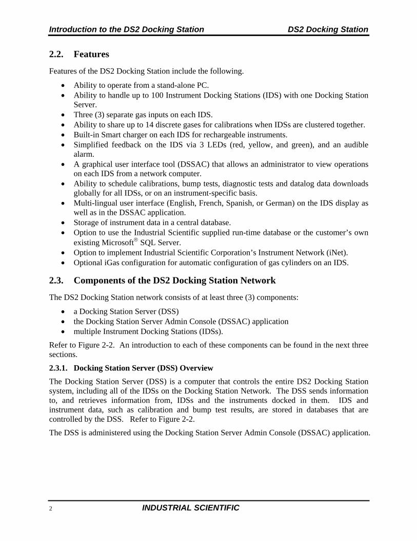
2.2. Features
Features of the DS2 Docking Station include the following.
Ability to operate from a stand-alone PC. Ability to handle up to 100 Instrument Docking Stations (IDS) with one Docking Station
Server. Three (3) separate gas inputs on each IDS. Ability to share up to 14 discrete gases for calibrations when IDSs are clustered together. Built-in Smart charger on each IDS for rechargeable instruments. Simplified feedback on the IDS via 3 LEDs (red, yellow, and green), and an audible
alarm. A graphical user interface tool (DSSAC) that allows an administrator to view operations
on each IDS from a network computer. Ability to schedule calibrations, bump tests, diagnostic tests and datalog data downloads
globally for all IDSs, or on an instrument-specific basis. Multi-lingual user interface (English, French, Spanish, or German) on the IDS display as
well as in the DSSAC application. Storage of instrument data in a central database. Option to use the Industrial Scientific supplied run-time database or the customer’s own
existing Microsoft SQL Server. Option to implement Industrial Scientific Corporation’s Instrument Network (iNet). Optional iGas configuration for automatic configuration of gas cylinders on an IDS.
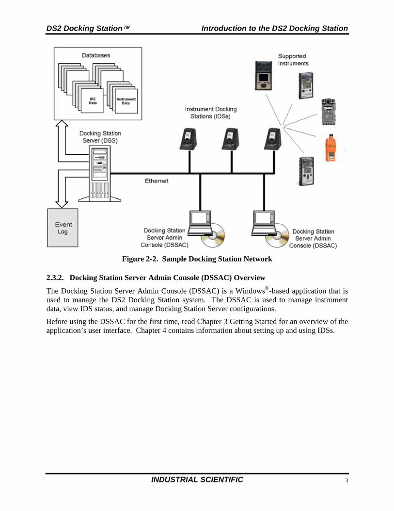
2.3. Components of the DS2 Docking Station Network
The DS2 Docking Station network consists of at least three (3) components:
a Docking Station Server (DSS) the Docking Station Server Admin Console (DSSAC) application multiple Instrument Docking Stations (IDSs).
Refer to Figure 2-2. An introduction to each of these components can be found in the next three sections.
2.3.1. Docking Station Server (DSS) Overview
The Docking Station Server (DSS) is a computer that controls the entire DS2 Docking Station system, including all of the IDSs on the Docking Station Network. The DSS sends information to, and retrieves information from, IDSs and the instruments docked in them. IDS and instrument data, such as calibration and bump test results, are stored in databases that are controlled by the DSS. Refer to Figure 2-2.
The DSS is administered using the Docking Station Server Admin Console (DSSAC) application.
DS2 Docking Station Introduction to the DS2 Docking Station
INDUSTRIAL SCIENTIFIC 5
Figure 2-2. Sample Docking Station Network
2.3.2. Docking Station Server Admin Console (DSSAC) Overview
The Docking Station Server Admin Console (DSSAC) is a Windows-based application that is used to manage the DS2 Docking Station system. The DSSAC is used to manage instrument data, view IDS status, and manage Docking Station Server configurations.
Before using the DSSAC for the first time, read Chapter 3 Getting Started for an overview of the application’s user interface. Chapter 4 contains information about setting up and using IDSs.
Introduction to the DS2 Docking Station DS2 Docking Station
6 INDUSTRIAL SCIENTIFIC
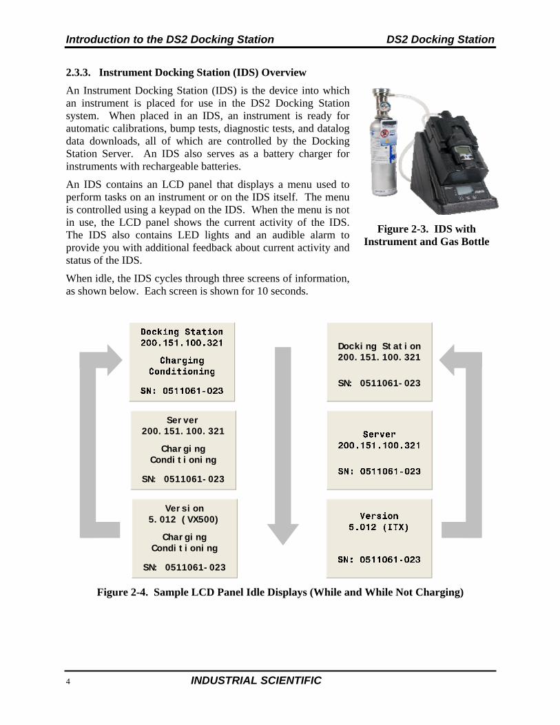
2.3.3. Instrument Docking Station (IDS) Overview
An Instrument Docking Station (IDS) is the device into which an instrument is placed for use in the DS2 Docking Station system. When placed in an IDS, an instrument is ready for automatic calibrations, bump tests, diagnostic tests, and datalog data downloads, all of which are controlled by the Docking Station Server. An IDS also serves as a battery charger for instruments with rechargeable batteries.
An IDS contains an LCD panel that displays a menu used to perform tasks on an instrument or on the IDS itself. The menu is controlled using a keypad on the IDS. When the menu is not in use, the LCD panel shows the current activity of the IDS. The IDS also contains LED lights and an audible alarm to provide you with additional feedback about current activity and status of the IDS.
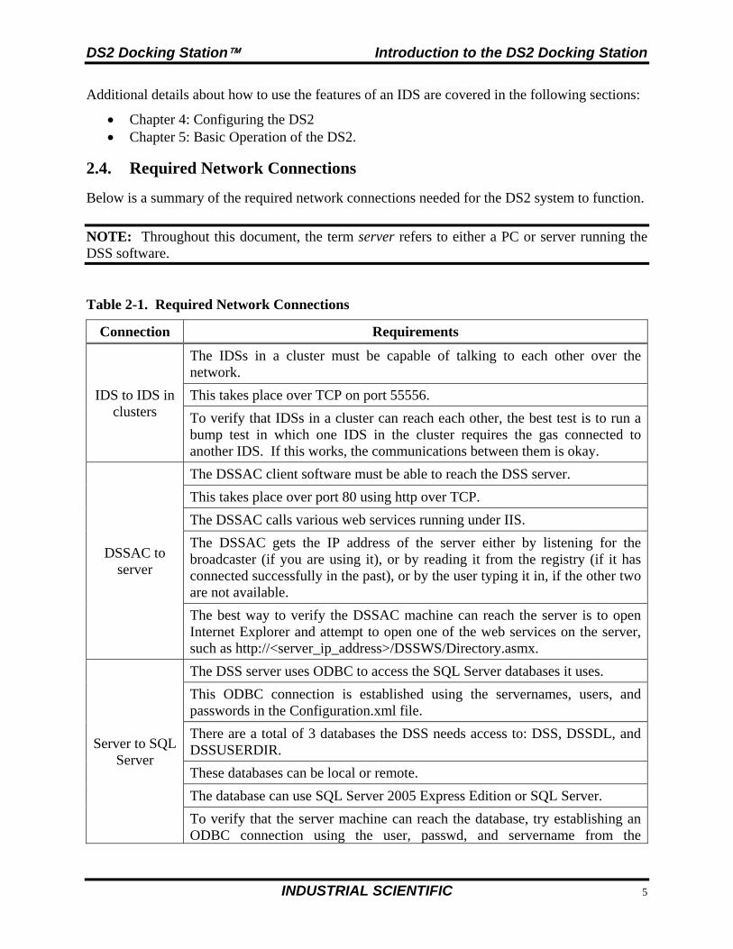
When idle, the IDS cycles through three screens of information, as shown below. Each screen is shown for 10 seconds.
Figure 2-3. IDS with Instrument and Gas Bottle
Docking Station200.151.100.321
SN: 0511061-023
Server200.151.100.321
ChargingConditioning
SN: 0511061-023
Version5.012 (VX500)
ChargingConditioning
SN: 0511061-023
Figure 2-4. Sample LCD Panel Idle Displays (While and While Not Charging)
DS2 Docking Station Introduction to the DS2 Docking Station
INDUSTRIAL SCIENTIFIC 7
Additional details about how to use the features of an IDS are covered in the following sections:
Chapter 4: Configuring the DS2 Chapter 5: Basic Operation of the DS2.
2.4. Required Network Connections
Below is a summary of the required network connections needed for the DS2 system to function.
NOTE: Throughout this document, the term server refers to either a PC or server running the DSS software.
Table 2-1. Required Network Connections
Connection Requirements
IDS to IDS in clusters
The IDSs in a cluster must be capable of talking to each other over the network.
This takes place over TCP on port 55556.
To verify that IDSs in a cluster can reach each other, the best test is to run a bump test in which one IDS in the cluster requires the gas connected to another IDS. If this works, the communications between them is okay.
DSSAC to server
The DSSAC client software must be able to reach the DSS server.
This takes place over port 80 using http over TCP.
The DSSAC calls various web services running under IIS.
The DSSAC gets the IP address of the server either by listening for the broadcaster (if you are using it), or by reading it from the registry (if it has connected successfully in the past), or by the user typing it in, if the other two are not available.
The best way to verify the DSSAC machine can reach the server is to open Internet Explorer and attempt to open one of the web services on the server, such as http://<server_ip_address>/DSSWS/Directory.asmx.
Server to SQL Server
The DSS server uses ODBC to access the SQL Server databases it uses.
This ODBC connection is established using the servernames, users, and passwords in the Configuration.xml file.
There are a total of 3 databases the DSS needs access to: DSS, DSSDL, and DSSUSERDIR.
These databases can be local or remote.
The database can use SQL Server 2005 Express Edition or SQL Server.
To verify that the server machine can reach the database, try establishing an ODBC connection using the user, passwd, and servername from the
Introduction to the DS2 Docking Station DS2 Docking Station
8 INDUSTRIAL SCIENTIFIC
Connection Requirements
Configuration.xml file.
Server to iNet
If you are subscribed to iNet, your DSS server must be able to reach iNet through the internet.
This communications occurs via https over TCP using port 80 and 443.
The iNet account and password must be correct in the Configuration.xml file.
The “DS2 iNet connector” service on your DSS server must be running under a user account that has access to the internet.
To IDS(s)
Each IDS must be able to reach the server, and the server must be able to reach the IDS(s).
This communication is XML over http, using TCP/IP.
This takes place on port 80.
The IDS posts XML to an ASP.NET page running under IIS. The ASP.NET page used by the IDSs is shown below. http://<server_ip_address>/DSSWS/Server.aspx
Each IDS contacts the server once each minute, unless the IDS is in the middle of a long operation, in which case it contacts the server after the operation is over.
The IDS learns the server IP address either by listening for the broadcaster (if you are using it), or by being programmed with the server IP using DS.Config.
The Server learns of the IDS IP when the IDS contacts the server (the server merely replies).
The IDS can have either a dynamic or static IP address.
If a static IP address is used, you must set the address on the IDS using HyperTerminal and a serial cable.
To verify the IDS is reaching the server, turn on the tracelog and look for messages from the IDS in question. If there are any, it is reaching the server.
Broadcaster to Network
The “DS2 Broadcaster“ is a service that runs on the DSS server, broadcasting the IP address of the DSS server, to be received by any IDS and/or DSSAC running on the network.
The broadcasts take place from the server via UDP on port 55555.
DS2 Docking Station Getting Started
INDUSTRIAL SCIENTIFIC 9
Getting Started
Chapter
3
3.1. Introduction
This chapter explains how to install the DSS Software package onto a computer system to be used on either a server-based operating system or a PC-based system. It also explains how to begin using the DSSAC application to administer your DS2 Docking Station system.
This chapter is divided into the following topics: Server requirements for software installation PC requirements for software installation Installing Microsoft Internet Information Services (IIS) Installing Microsoft Message Queuing (MSMQ) Installing the Docking Station Server (DSS) software Loading the installer software Installation wizard for DSS Database preparation options for first time installations Selecting the database option iNet considerations Installing the Docking Station Server Admin Console (DSSAC) software Installing and running the Docking Station Configurator software Assigning a static IP address to a sever or PC Disabling the DS2 Broadcaster Configuring Windows XP firewall Starting the DSSAC application Specifying the DSS IP address
Each of these topics is explained in the sections that follow.
Getting Started DS2 Docking Station
10 INDUSTRIAL SCIENTIFIC
3.2. Requirements for Software Installation
Before installing the software make sure that your PC and Server meet the following minimum requirements.
3.2.1. Server Requirements
Pentium III, 800 MHz (or higher) 256 MB RAM 4 GB free disk space Supported operating systems:
o Windows 2000 Server (DSS Version 8.0 and earlier), Advanced Server or Datacenter Server with SP3 or higher
o Windows 2003 Standard Edition, Web Edition, Enterprise Edition or Datacenter Edition)
o Windows 2000 Professional (DSS Version 8.0 and earlier)or Windows XP (These support 5 Docking Stations or less).
o Windows Vista o Windows 7 (DSS Version 8.0 and higher) o Windows 2008 (DSS Version 7.0 and higher) o Windows 8 (DSS Version 9.1 and higher) o Windows Server 2012 (DSS Version 9.1 and higher)
Supported operating system languages (for installation and running):
o English o French o German o Spanish o Czech o Polish o Russian o Other Western Europe Latin-based languages (i.e., “Latin-1” languages per
Windows) should also work, but have not been specifically tested. These include: Afrikaans, Basque, Catalan, Danish, Dutch, Faeroese, Finnish, Galician (Spain), Icelandic, Indonesian, Italian, Malay, Norwegian, Portuguese, Swahili, and Swedish.
o The SQL Server (or SQL Server 2005 Express Edition) database must be configured to use a Collation type within the Windows Latin codepage of 1252. (NOTE: If the DS2 database has any other collation type, it prevents the DS2 software from functioning properly.) The SQL Server (or SQL Server 2005 Express Edition) will automatically default to “collation type” within the proper codepage of 1252 if installed under the Latin-based languages listed above. Installing SQL Server under a non-Latin-based operating system may result in a non-Latin collation type for the DS2 database. Database administrators also have the ability to change a database’s collation type. Changing the collation type of the DS2 database to anything other than a Latin collation type is not be supported.
DS2 Docking Station Getting Started
INDUSTRIAL SCIENTIFIC 11
Internet Information Services (IIS) must be installed to the operating system if not already present (may require the Operating System CD)
Message Queuing (MSMQ) must be installed to operating system (may require the operating system CD).
NOTE: Server software is supported on English, French, German, Spanish, Czech, Polish, or Russian operating systems. Other Latin-based language operating systems may work, but they have not been fully tested.
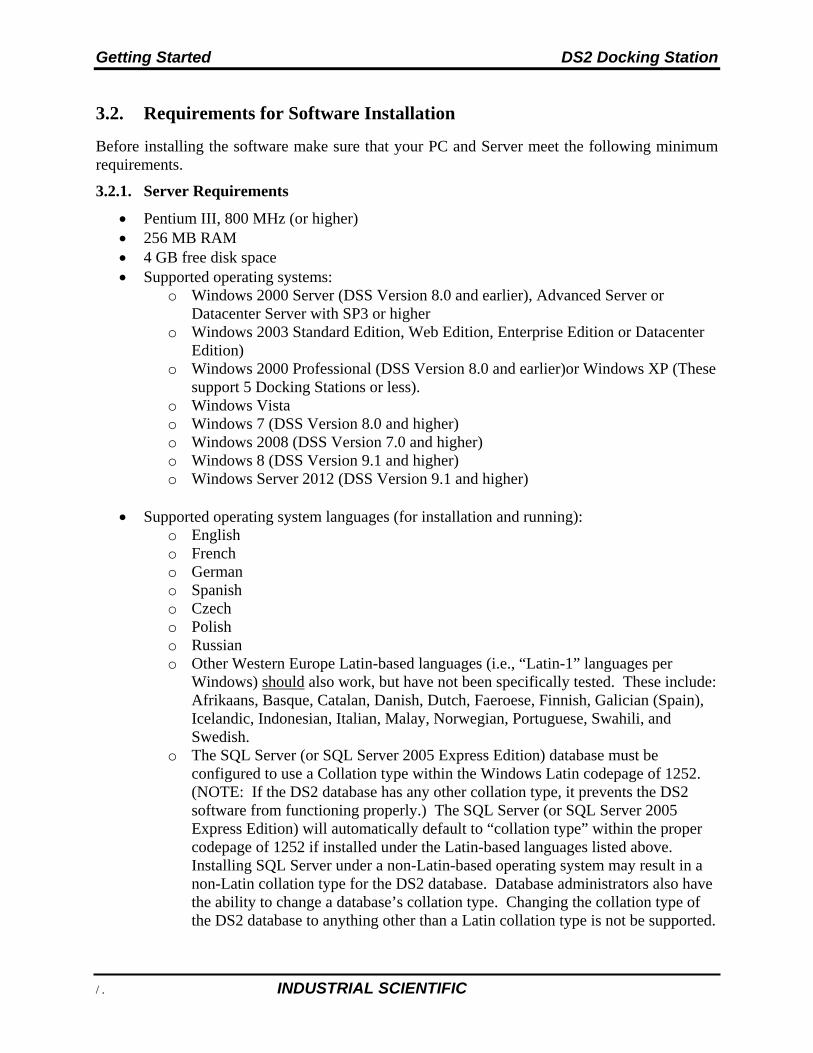
The collation type of the database can be seen using SQL Server Enterprise manager and examining the Properties of a database as in the screenshot below.
Figure 3-1. Determining the Collation Type of a Database
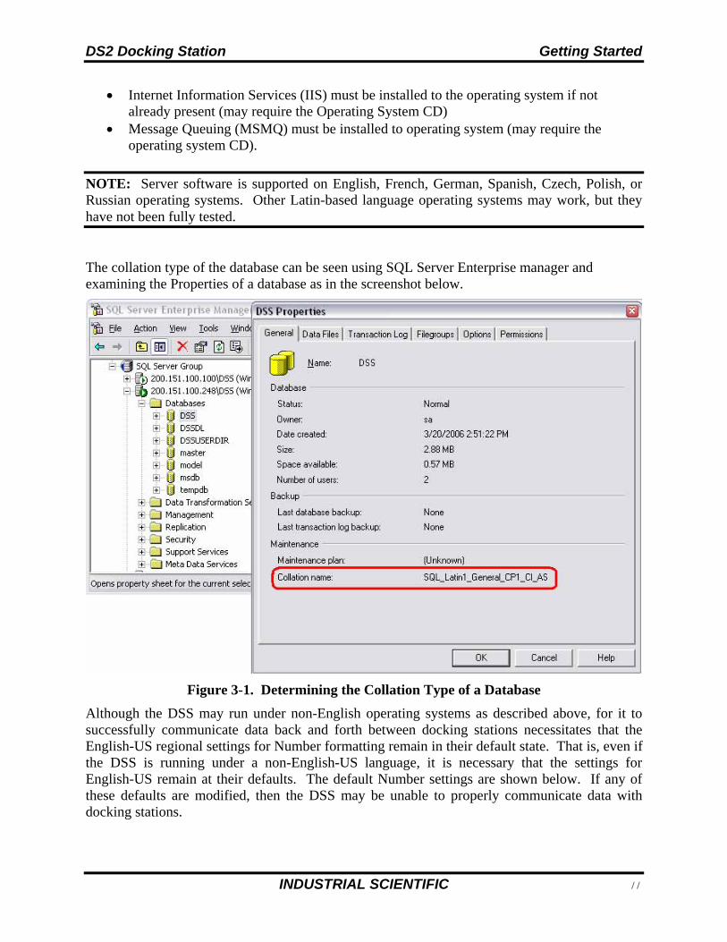
Although the DSS may run under non-English operating systems as described above, for it to successfully communicate data back and forth between docking stations necessitates that the English-US regional settings for Number formatting remain in their default state. That is, even if the DSS is running under a non-English-US language, it is necessary that the settings for English-US remain at their defaults. The default Number settings are shown below. If any of these defaults are modified, then the DSS may be unable to properly communicate data with docking stations.
Getting Started DS2 Docking Station
12 INDUSTRIAL SCIENTIFIC
Figure 3-2. Default English-US Regional Options for “Numbers”
3.2.2. PC Requirements
Pentium III, 800 MHz (or higher) 256 MB RAM 4 GB free disk space Windows XP or Windows Vista or Windows 2003, Windows 7, Windows 8, Windows 2008
or Windows Server 2012. Internet Information Services (IIS) must be installed to the Operating System if not
already present (may require the Operating System CD) Message Queuing (MSMQ) must be installed to Operating System (may require the
Operating System CD)
3.2.3. Running DSSAC v8.6 and higher on a machine that is to run on FDCC Settings.
DSSAC supports Federal Desktop Core Configuration (FDCC) settings starting with v8.6. To apply FDCC settings when using DSSAC v8.6, all DSSAC user passwords must be changed before applying FDCC settings if either of these scenarios is true:
DS2 Docking Station Getting Started
INDUSTRIAL SCIENTIFIC 13
A fresh installation of DSS/DSSAC v8.6 with existing databases (earlier than v8.6) DSS and DSSAC are being upgraded to v8.6 from any prior version
To support the DSS User password reset functionality, DSS/DSSAC v8.6 and above must use DS.Configurator v8.6 or above.
If FDCC settings were applied before changing the passwords, complete the following procedures:
1. Disable the FDCC settings
Go to Start > Control Panel > Administrative Tools > Local Security Policy. The Group Policy dialog appears.
Under the "Local Policies" heading, select "Security Options" and look for the item, "System cryptography: Use FIPS compliant algorithms for encryption, hashing, and signing."
Disable this item. 2. Change all DSSAC user passwords.
3. Enable the FDCC setting that was disabled in step 1.
3.2.4. Additional Requirements and Warnings
WARNING: PCs or laptops having two network adapters will not allow the DSS to properly function. Do not install to a laptop that has both a built in LAN adapter and a built in Wireless adapter. If the laptop has a removable wireless card, remove the wireless card and place laptop on a LAN via Ethernet cable while doing the install.
WARNING: When connecting a single IDS to either a server or PC, an Ethernet cross over cable must be used. If you are connecting multiple IDSs to a network, standard Ethernet cables must be used.
WARNING: If you are installing the DSS software on a stand alone server or PC, any network device must be connected to the PC via an Ethernet Cable, for the software to install. Simply connecting a DS2 or any other network device such as a hub or router to the server or PC will be adequate. If no devices are connected to the computer, the DSS will not install.
NOTE: If installing the software onto a Windows XP operating system, some screen shots may have some inaccuracies; depending on if the PC views are set for Classic/Traditional View, or XP View.
NOTE: Throughout this document, Internet Information Services will be referred to as IIS, and Message Queuing will be referred to as MSMQ.
Getting Started DS2 Docking Station
14 INDUSTRIAL SCIENTIFIC
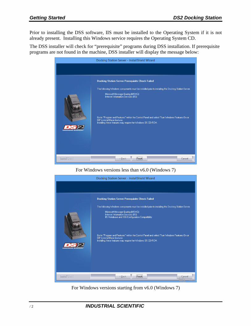
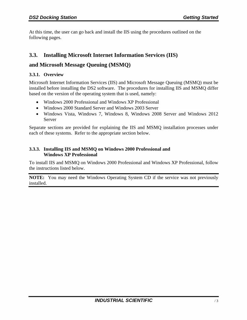
Prior to installing the DSS software, IIS must be installed to the Operating System if it is not already present. Installing this Windows service requires the Operating System CD.
The DSS installer will check for “prerequisite” programs during DSS installation. If prerequisite programs are not found in the machine, DSS installer will display the message below:
For Windows versions less than v6.0 (Windows 7)
For Windows versions starting from v6.0 (Windows 7)
DS2 Docking Station Getting Started
INDUSTRIAL SCIENTIFIC 15
At this time, the user can go back and install the IIS using the procedures outlined on the following pages.
3.3. Installing Microsoft Internet Information Services (IIS)
and Microsoft Message Queuing (MSMQ)
3.3.1. Overview
Microsoft Internet Information Services (IIS) and Microsoft Message Queuing (MSMQ) must be installed before installing the DS2 software. The procedures for installing IIS and MSMQ differ based on the version of the operating system that is used, namely:
Windows 2000 Professional and Windows XP Professional Windows 2000 Standard Server and Windows 2003 Server Windows Vista, Windows 7, Windows 8, Windows 2008 Server and Windows 2012
Server
Separate sections are provided for explaining the IIS and MSMQ installation processes under each of these systems. Refer to the appropriate section below.
3.3.3. Installing IIS and MSMQ on Windows 2000 Professional and Windows XP Professional
To install IIS and MSMQ on Windows 2000 Professional and Windows XP Professional, follow the instructions listed below.
NOTE: You may need the Windows Operating System CD if the service was not previously installed.
Getting Started DS2 Docking Station
16 INDUSTRIAL SCIENTIFIC
Step Instruction
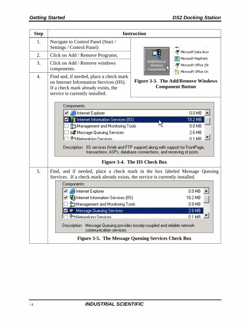
1. Navigate to Control Panel (Start / Settings / Control Panel)
Figure 3-3. The Add/Remove Windows Component Button
2. Click on Add / Remove Programs.
3. Click on Add / Remove windows components.
4. Find and, if needed, place a check mark on Internet Information Services (IIS). If a check mark already exists, the service is currently installed.
Figure 3-4. The IIS Check Box
5. Find, and if needed, place a check mark in the box labeled Message Queuing Services. If a check mark already exists, the service is currently installed.
Figure 3-5. The Message Queuing Services Check Box
DS2 Docking Station Getting Started
INDUSTRIAL SCIENTIFIC 17
Step Instruction
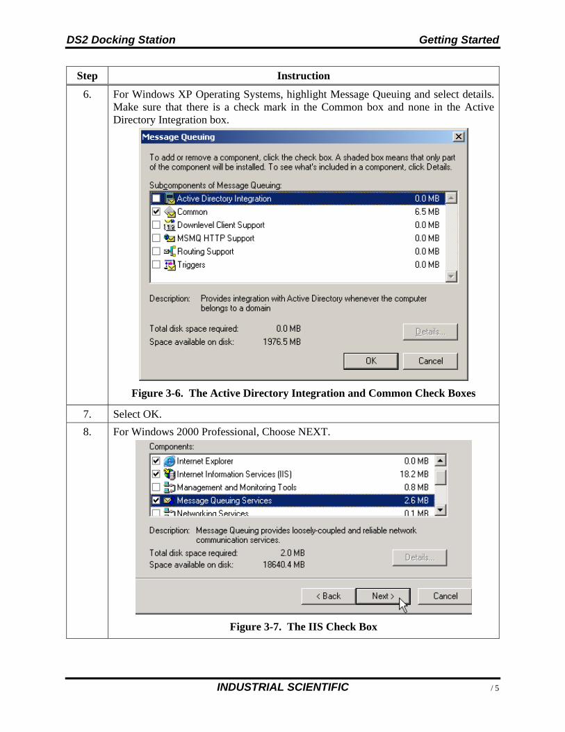
6. For Windows XP Operating Systems, highlight Message Queuing and select details. Make sure that there is a check mark in the Common box and none in the Active Directory Integration box.
Figure 3-6. The Active Directory Integration and Common Check Boxes
7. Select OK.
8. For Windows 2000 Professional, Choose NEXT.
Figure 3-7. The IIS Check Box
Getting Started DS2 Docking Station
18 INDUSTRIAL SCIENTIFIC
Step Instruction
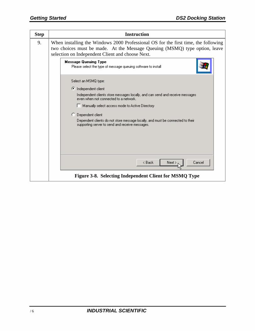
9. When installing the Windows 2000 Professional OS for the first time, the following two choices must be made. At the Message Queuing (MSMQ) type option, leave selection on Independent Client and choose Next.
Figure 3-8. Selecting Independent Client for MSMQ Type
DS2 Docking Station Getting Started
INDUSTRIAL SCIENTIFIC 19
Step Instruction
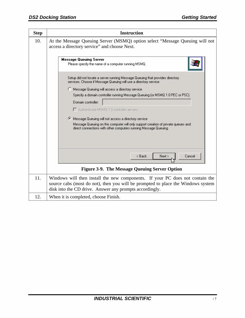
10. At the Message Queuing Server (MSMQ) option select “Message Queuing will not access a directory service” and choose Next.
Figure 3-9. The Message Queuing Server Option
11. Windows will then install the new components. If your PC does not contain the source cabs (most do not), then you will be prompted to place the Windows system disk into the CD drive. Answer any prompts accordingly.
12. When it is completed, choose Finish.
Getting Started DS2 Docking Station
20 INDUSTRIAL SCIENTIFIC
3.3.4. Installing IIS and MSMQ on Windows 2000 Standard Server and Windows 2003 Server Web Edition
To install IIS and MSMQ on Windows 2000 Standard Server and Windows 2003 Server Web Edition, follow the instructions below.
NOTE: You may need the Windows Operating System CD if the services were not previously installed.
Step Instruction
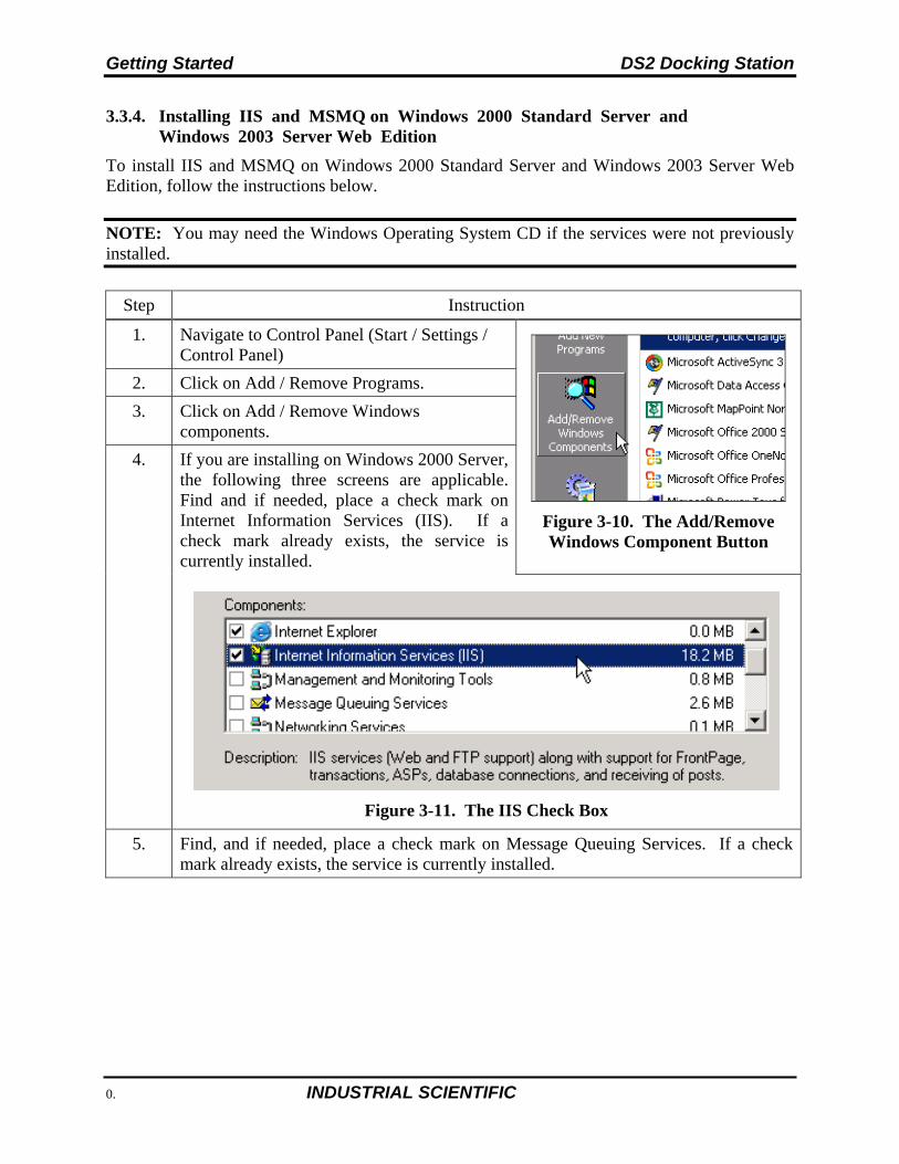
1. Navigate to Control Panel (Start / Settings / Control Panel)
Figure 3-10. The Add/Remove Windows Component Button
2. Click on Add / Remove Programs.
3. Click on Add / Remove Windows components.
4. If you are installing on Windows 2000 Server, the following three screens are applicable. Find and if needed, place a check mark on Internet Information Services (IIS). If a check mark already exists, the service is currently installed.
Figure 3-11. The IIS Check Box
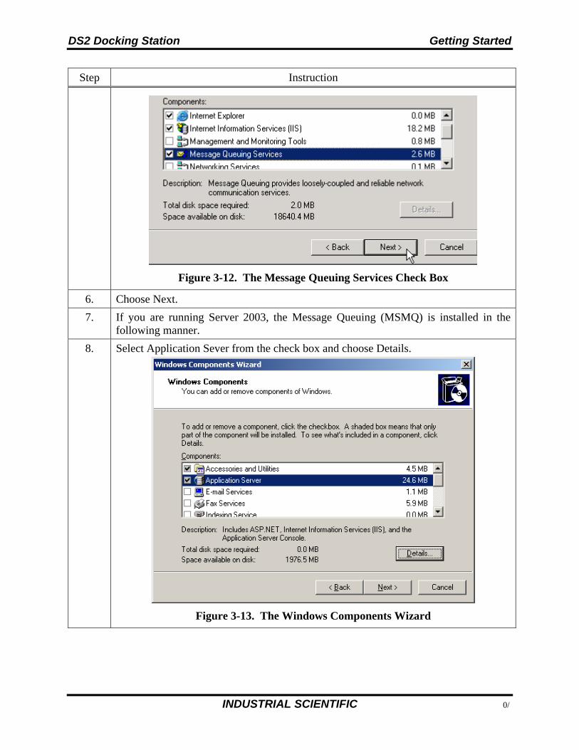
5. Find, and if needed, place a check mark on Message Queuing Services. If a check mark already exists, the service is currently installed.
DS2 Docking Station Getting Started
INDUSTRIAL SCIENTIFIC 21
Step Instruction
Figure 3-12. The Message Queuing Services Check Box
6. Choose Next.
7. If you are running Server 2003, the Message Queuing (MSMQ) is installed in the following manner.
8. Select Application Sever from the check box and choose Details.
Figure 3-13. The Windows Components Wizard
Getting Started DS2 Docking Station
22 INDUSTRIAL SCIENTIFIC
Step Instruction
9. Make sure that ASP.NET, Internet Information Services (IIS), and Message Queuing are checked.
Figure 3-14. The ASP.NET, IIS, and Message Queuing Check Boxes
DS2 Docking Station Getting Started
INDUSTRIAL SCIENTIFIC 23
Step Instruction
10. Highlight Message Queuing and click Details. Make sure that there is a check mark in the box marked Common and no check mark in the Active Directory Integration box, and then click OK.
Figure 3-15. The Message Queuing Dialog Box
Getting Started DS2 Docking Station
24 INDUSTRIAL SCIENTIFIC
Step Instruction
11. When installing the Windows 2000 Server OS for the first time, the following two choices must be made. At the Message Queuing (MSMQ) type option, leave selection on Independent Client and choose Next. At the Message Queuing Type option, leave selection on Independent Client and choose Next.
Figure 3-16. The Message Queuing Type Option
DS2 Docking Station Getting Started
INDUSTRIAL SCIENTIFIC 25
Step Instruction
12. At the Message Queuing Server option select “Message Queuing will not access a directory service” and choose Next.
Figure 3-17. The Message Queuing Server Option
13. Windows will then install the new components. It your PC does not contain the source cabs (most do not), then you will be prompted to place the Windows system disk into the CD drive. Answer any prompts accordingly.
14. When it is completed, choose Finish, and reboot the PC or server.
15. After the IIS is installed, the PC or Server is now ready to install the DSS software.
3.3.5. Installing IIS and MSMQ on Windows Vista, Windows 7, Windows 8, Windows 2008 Server and Windows 2012 Server
To install IIS and MSMQ on these operating systems follow the instructions below.
NOTE: You may need the Windows Operating System CD if the services were not previously installed.
Starting with version 5.1 of the DS2 Software suite, support has been added to allow the software to run on the Windows Vista™ operating system. When installing any of the DS2 software applications on Vista™, the user will need to have “administrative” privileges. This is due to the new User Access Control (UAC) feature within Vista™. The following provides instructions on installing the DS2 Software suite on Vista™ operating system. For more information about Vista’s UAC, see the following link: http://www.microsoft.com/windows/products/windowsvista/features/details/useraccountcontrol.mspx
Getting Started DS2 Docking Station
26 INDUSTRIAL SCIENTIFIC
To install IIS and MSMQ on Windows Vista follow the instructions below.
Step Instruction
1. To avoid any problems with privileges, close the DS2 CD launcher if the autorun feature automatically starts it.
2. Browse to the DS2 CD and right-click on the DS2Launch application. Choose the Run as administrator option; provide an administrative password if required.
3. Install the DS2 applications as needed.
DS2 Docking Station Getting Started
INDUSTRIAL SCIENTIFIC 27
Step Instruction
4. If the current user does not have “administrative” privileges at the time of installation, the User Access Control (UAC) will prompt for an admin password as shown below.
5. Provide an administrative password and then continue with the install as usual.
Getting Started DS2 Docking Station
28 INDUSTRIAL SCIENTIFIC
The following images define which settings should be enabled for MSMQ and IIS Installed Windows Components settings under Vista, Windows 7, Windows 8, and Windows 2012.
MSMQ IIS
DS2 Docking Station Getting Started
INDUSTRIAL SCIENTIFIC 29
3.3.6. Installing IIS and MSMQ on Windows 2008
Step Instruction
1. Navigate to Control Panel (Start / Settings / Control).
2. Click on Programs / Features.
3. Click on Turn Windows Features On and Off; this is located in the window pane to the left.
4. Click on Features, then choose Add Features.
Getting Started DS2 Docking Station
30 INDUSTRIAL SCIENTIFIC
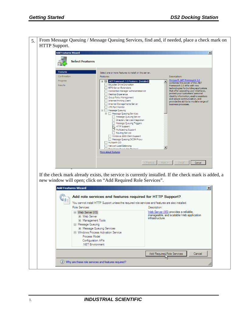
5. From Message Queuing / Message Queuing Services, find and, if needed, place a check mark on HTTP Support.
If the check mark already exists, the service is currently installed. If the check mark is added, a new window will open; click on “Add Required Role Services”.
DS2 Docking Station Getting Started
INDUSTRIAL SCIENTIFIC 31
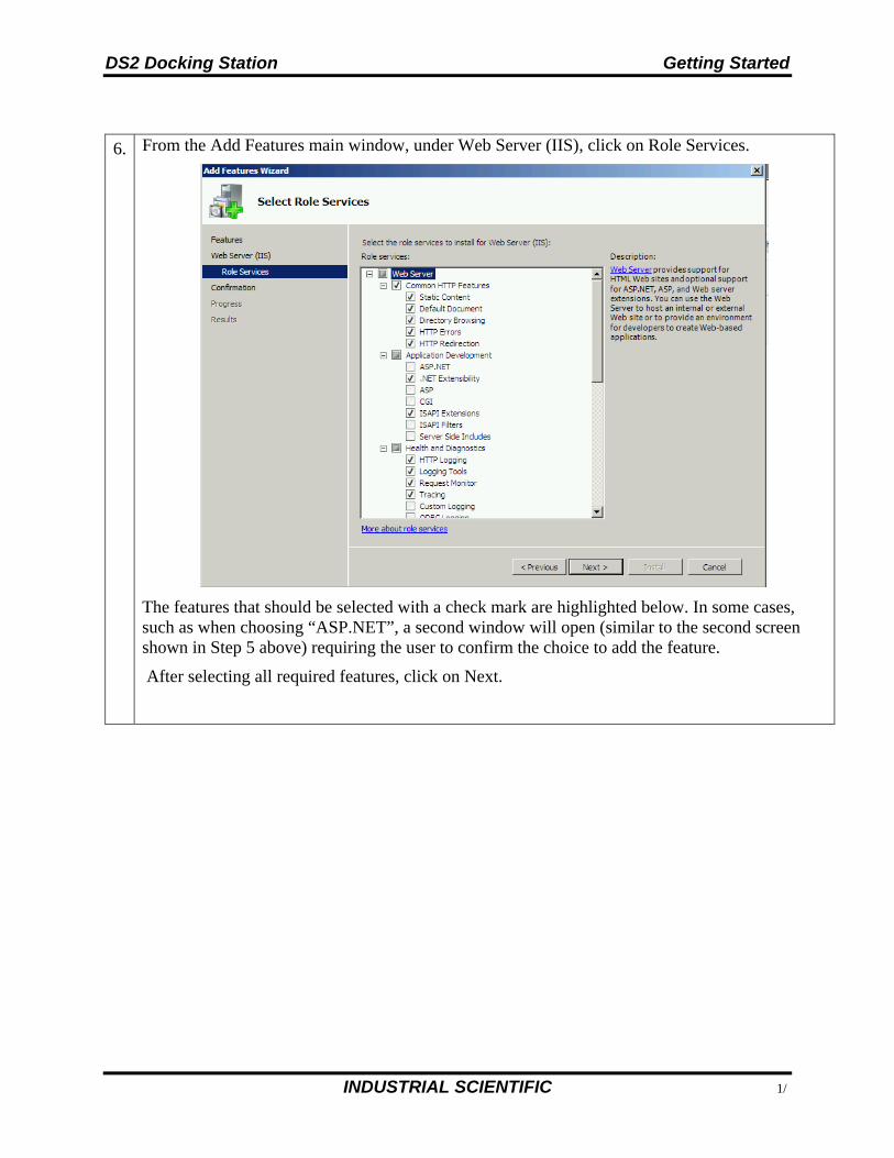
6. From the Add Features main window, under Web Server (IIS), click on Role Services.
The features that should be selected with a check mark are highlighted below. In some cases, such as when choosing “ASP.NET”, a second window will open (similar to the second screen shown in Step 5 above) requiring the user to confirm the choice to add the feature.
After selecting all required features, click on Next.
Getting Started DS2 Docking Station
32 INDUSTRIAL SCIENTIFIC
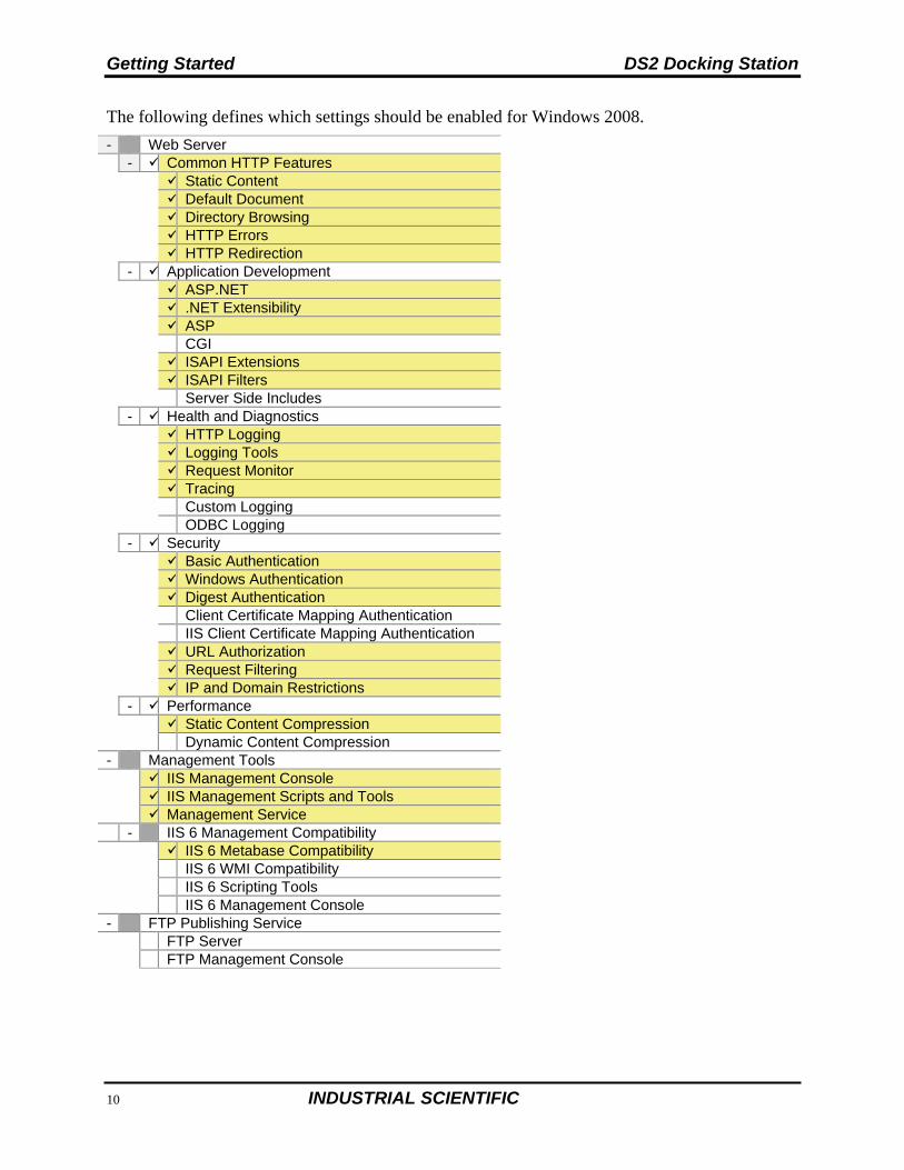
The following defines which settings should be enabled for Windows 2008.
- Web Server - Common HTTP Features
Static Content Default Document Directory Browsing HTTP Errors HTTP Redirection
- Application Development ASP.NET
.NET Extensibility ASP CGI ISAPI Extensions ISAPI Filters Server Side Includes
- Health and Diagnostics HTTP Logging
Logging Tools Request Monitor Tracing Custom Logging ODBC Logging
- Security Basic Authentication
Windows Authentication Digest Authentication Client Certificate Mapping Authentication IIS Client Certificate Mapping Authentication URL Authorization Request Filtering IP and Domain Restrictions
- Performance Static Content Compression
Dynamic Content Compression - Management Tools IIS Management Console
IIS Management Scripts and Tools Management Service
- IIS 6 Management Compatibility IIS 6 Metabase Compatibility
IIS 6 WMI Compatibility IIS 6 Scripting Tools IIS 6 Management Console
- FTP Publishing Service FTP Server
FTP Management Console
DS2 Docking Station Getting Started
INDUSTRIAL SCIENTIFIC 33
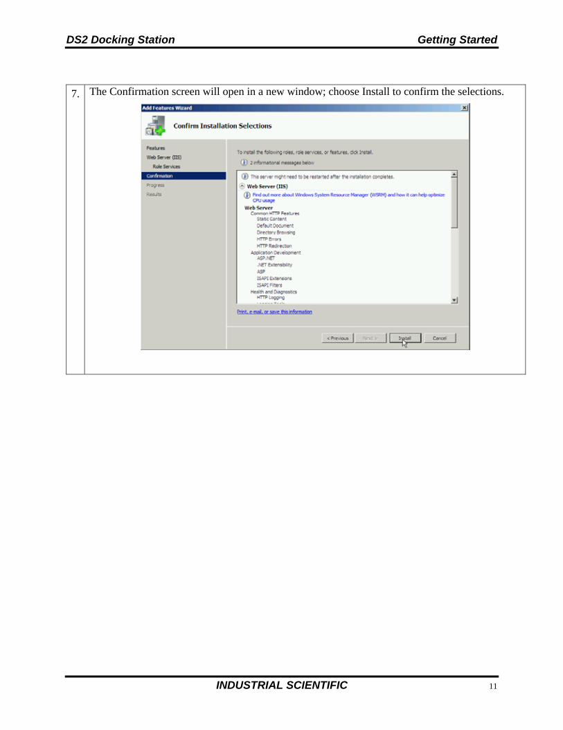
7. The Confirmation screen will open in a new window; choose Install to confirm the selections.
Getting Started DS2 Docking Station
34 INDUSTRIAL SCIENTIFIC
3.3.7. Installing IIS and MSMQ on Windows 7
Step Instruction
1. Navigate to Control Panel (Start / Settings / Control).
2. Click on Programs.
3. Click on Turn Windows features on or off.
DS2 Docking Station Getting Started
INDUSTRIAL SCIENTIFIC 35
Step Instruction
4. From the Microsoft Messaging Queue (MSMQ) Server / Microsoft message Queue (MSMQ) Server Core. Select MSMQ HTTP Support.
5. Select Internet Information Services / Web Management Tools. The features shown below with a check mark should be turned on.
6 In addition to the MSMQ and IIS features noted above in steps 4 and 5, other features are required (e.g., Security). Refer to the full list of Windows 7 features that should be selected as shown on page 25. After all features are selected, click OK.
Getting Started DS2 Docking Station
36 INDUSTRIAL SCIENTIFIC
3.4. Installing the Docking Station Server (DSS) Software
The procedures that follow are intended for the operating systems listed below:
Windows 2000 Standard Server Windows 2003 Server Web Edition Windows 2000 Professional Windows XP Professional (firewall must be configured) Windows Vista Windows 7 Windows 2008 Windows 8 Windows Server 2012.
The DSS software is installed in segments. These segments are outlined in the sections that follow.
3.5. Loading the Installer Software
To load the installer software, follow the instructions below.
Step Instruction
1. Place the DS2 Operating CD into your computer.
2. The CD will automatically run and the following window will appear.
Figure 3-18. The DS2 Installer Software Start-up Window
DS2 Docking Station Getting Started
INDUSTRIAL SCIENTIFIC 37
Step Instruction
The launcher displays seven language options on the screen, one representing each of the four languages supported. Click a language to re-display the Launcher in the chosen language.
3. Click on “Install Docking Station Server.” This will automatically launch the DSS installer. The first window that appears is the License Agreement.
4. This message will not be displayed in newer Windows operating systems, or if .NET Framework has been installed previously. Review the license agreement, choose “I agree,” and then click Install.
Figure 3-19. The License Agreement Window
5. The Installer will automatically install the .NET framework (if it currently is not installed). When this installation is complete, the following window will appear. Choose OK to continue the installation.
Figure 3-20. The .NET Framework Installation Complete Message Box
Getting Started DS2 Docking Station
38 INDUSTRIAL SCIENTIFIC
Step Instruction
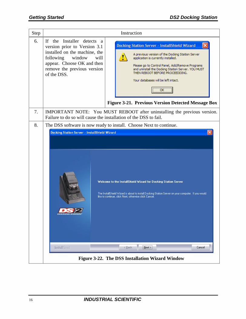
6. If the Installer detects a version prior to Version 3.1 installed on the machine, the following window will appear. Choose OK and then remove the previous version of the DSS.
Figure 3-21. Previous Version Detected Message Box
7. IMPORTANT NOTE: You MUST REBOOT after uninstalling the previous version. Failure to do so will cause the installation of the DSS to fail.
8. The DSS software is now ready to install. Choose Next to continue.
Figure 3-22. The DSS Installation Wizard Window
DS2 Docking Station Getting Started
INDUSTRIAL SCIENTIFIC 39
3.6. Installation Wizard for DSS
Step Instruction
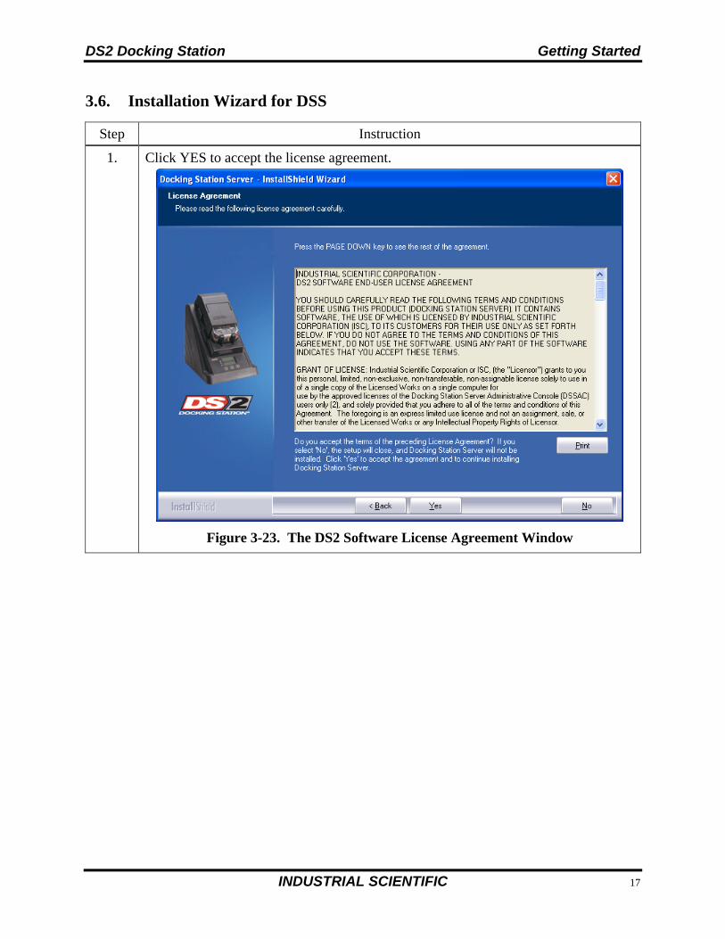
1. Click YES to accept the license agreement.
Figure 3-23. The DS2 Software License Agreement Window
Getting Started DS2 Docking Station
40 INDUSTRIAL SCIENTIFIC
Step Instruction
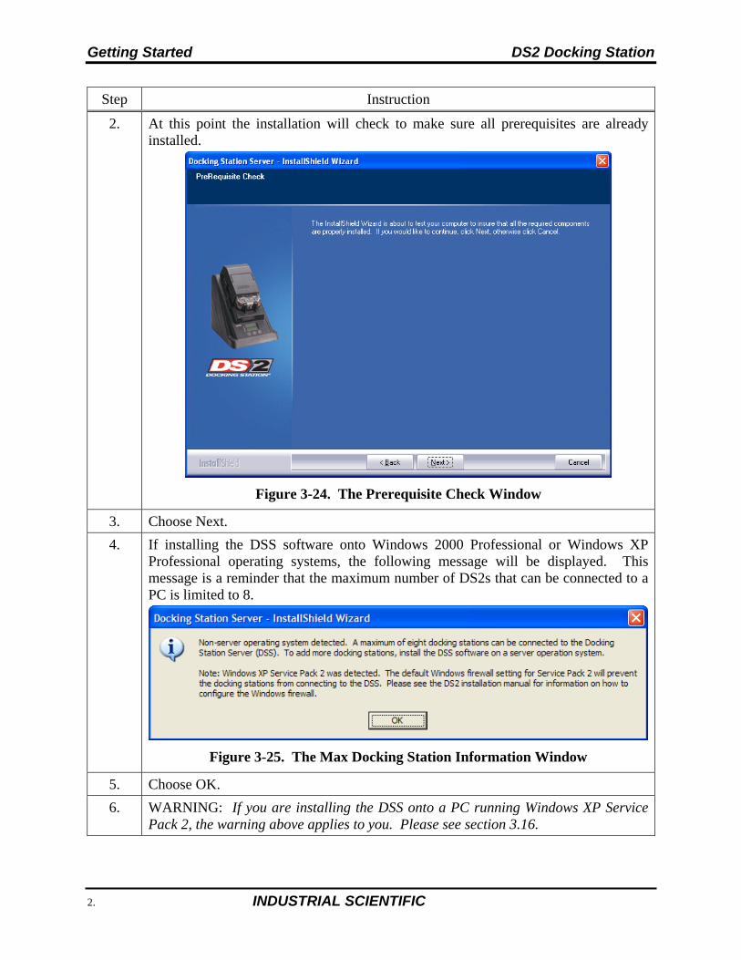
2. At this point the installation will check to make sure all prerequisites are already installed.
Figure 3-24. The Prerequisite Check Window
3. Choose Next.
4. If installing the DSS software onto Windows 2000 Professional or Windows XP Professional operating systems, the following message will be displayed. This message is a reminder that the maximum number of DS2s that can be connected to a PC is limited to 8.
Figure 3-25. The Max Docking Station Information Window
5. Choose OK.
6. WARNING: If you are installing the DSS onto a PC running Windows XP Service Pack 2, the warning above applies to you. Please see section 3.16.
DS2 Docking Station Getting Started
INDUSTRIAL SCIENTIFIC 41
Step Instruction
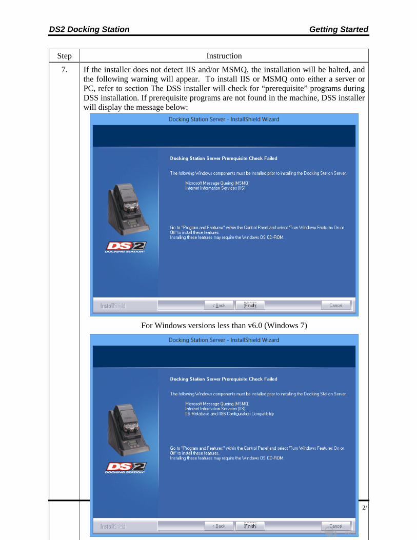
7. If the installer does not detect IIS and/or MSMQ, the installation will be halted, and the following warning will appear. To install IIS or MSMQ onto either a server or PC, refer to section The DSS installer will check for “prerequisite” programs during DSS installation. If prerequisite programs are not found in the machine, DSS installer will display the message below:
For Windows versions less than v6.0 (Windows 7)
Getting Started DS2 Docking Station
42 INDUSTRIAL SCIENTIFIC
3.7. Database Preparation Options for First Time Installations
3.7.1. Overview
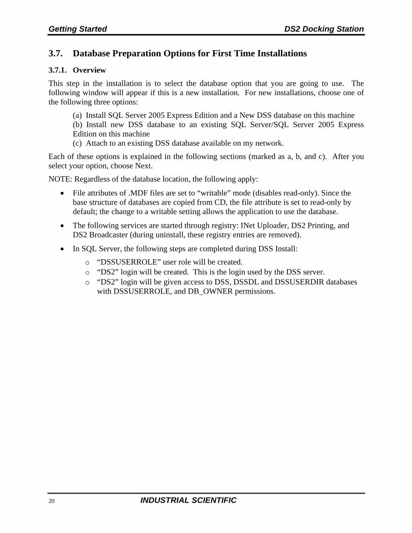
This step in the installation is to select the database option that you are going to use. The following window will appear if this is a new installation. For new installations, choose one of the following three options:
(a) Install SQL Server 2005 Express Edition and a New DSS database on this machine (b) Install new DSS database to an existing SQL Server/SQL Server 2005 Express Edition on this machine (c) Attach to an existing DSS database available on my network.
Each of these options is explained in the following sections (marked as a, b, and c). After you select your option, choose Next.
NOTE: Regardless of the database location, the following apply:
File attributes of .MDF files are set to “writable” mode (disables read-only). Since the base structure of databases are copied from CD, the file attribute is set to read-only by default; the change to a writable setting allows the application to use the database.
The following services are started through registry: INet Uploader, DS2 Printing, and DS2 Broadcaster (during uninstall, these registry entries are removed).
In SQL Server, the following steps are completed during DSS Install:
o “DSSUSERROLE” user role will be created. o “DS2” login will be created. This is the login used by the DSS server. o “DS2” login will be given access to DSS, DSSDL and DSSUSERDIR databases
with DSSUSERROLE, and DB_OWNER permissions.
DS2 Docking Station Getting Started
INDUSTRIAL SCIENTIFIC 43
Figure 3-27. The Setup Type Window
NOTE: When performing a fresh install of DSS that includes SQL Server 2005 Express Edition, newer versions of the installer no longer ask for passwords for the SA, SQL DSSUSER and DSSAC DSSUSER accounts. The default value of DS2user will be used for all three.
Getting Started DS2 Docking Station
44 INDUSTRIAL SCIENTIFIC
WelcomeWelcome
LicenseLicense
SA PasswordSA Password
DS2userEnter Password
Install MSDE/New DSS
Existing SQL/New DSS
(DB Files Present)
Start InstallStart Install
Install
Test for PrerequisitesTest for Prerequisites
Fresh Install
Existing SQL/New DSS
Select DB OptionSelect DB Option
Install MSDE/New DSS Existing SQL/New DSS on local
Select a DSS database option
Existing SQL/Existing DSS elsewhere
Perform Upgrade?Perform Upgrade?
The Docking Station Server installer has detected existing database files. Do you want
to perform an upgrade using those files?
Existing SQL/Existing DSS
Data Files Found
Install MSDE/New DSS
(DB Files Present)
Instance NameInstance Name
DSSInstance Name
SQL Server LocationSQL Server Location
Server Name
Do NotUse Files
AbortAbort
Remove FilesWarning
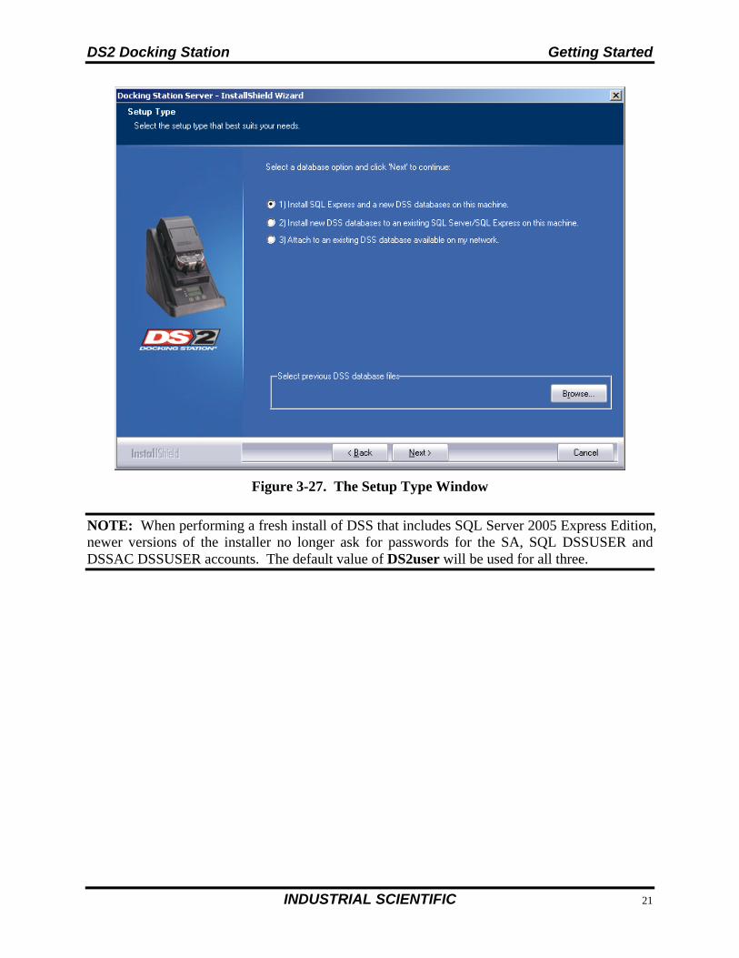
Figure 3-28. Simplified DSS Installation Flowchart
DS2 Docking Station Getting Started
INDUSTRIAL SCIENTIFIC 45
3.7.2a. Install SQL Server 2005 Express Edition and a New DSS Database on This Machine
Step Instruction
1. Start installation.
NOTE: A new SQL Server 2005 Express Edition database installed with a fresh DSS installation will use the following default account information:
Account User Password
SA Password SA DS2user DS2 DB User Login DS2 DS2user DSSAC Default Admin User Login DSSUSER DS2user DSSAC Read-only User Login GUEST guest
3.7.2b. Install New DSS Database to an Existing SQL Server/SQL Server 2005 Express Edition on This Machine
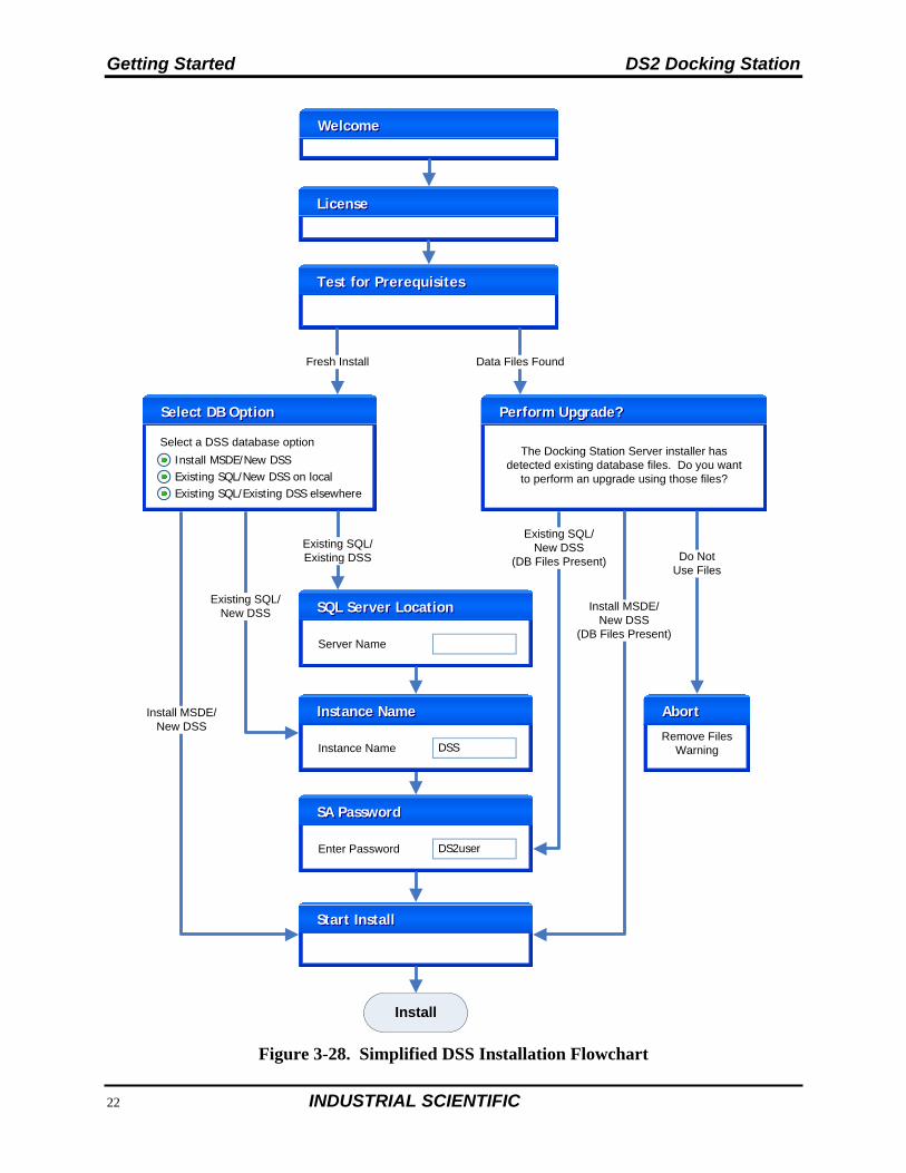
Step Instruction
1. Enter the database Instance name and choose Next.
Figure 3-29. Entering the Database Instance Name
2. Select a System Administrator Password and choose Next.
Getting Started DS2 Docking Station
46 INDUSTRIAL SCIENTIFIC
Step Instruction
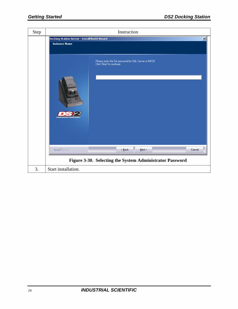
Figure 3-30. Selecting the System Administrator Password
3. Start installation.
DS2 Docking Station Getting Started
INDUSTRIAL SCIENTIFIC 47
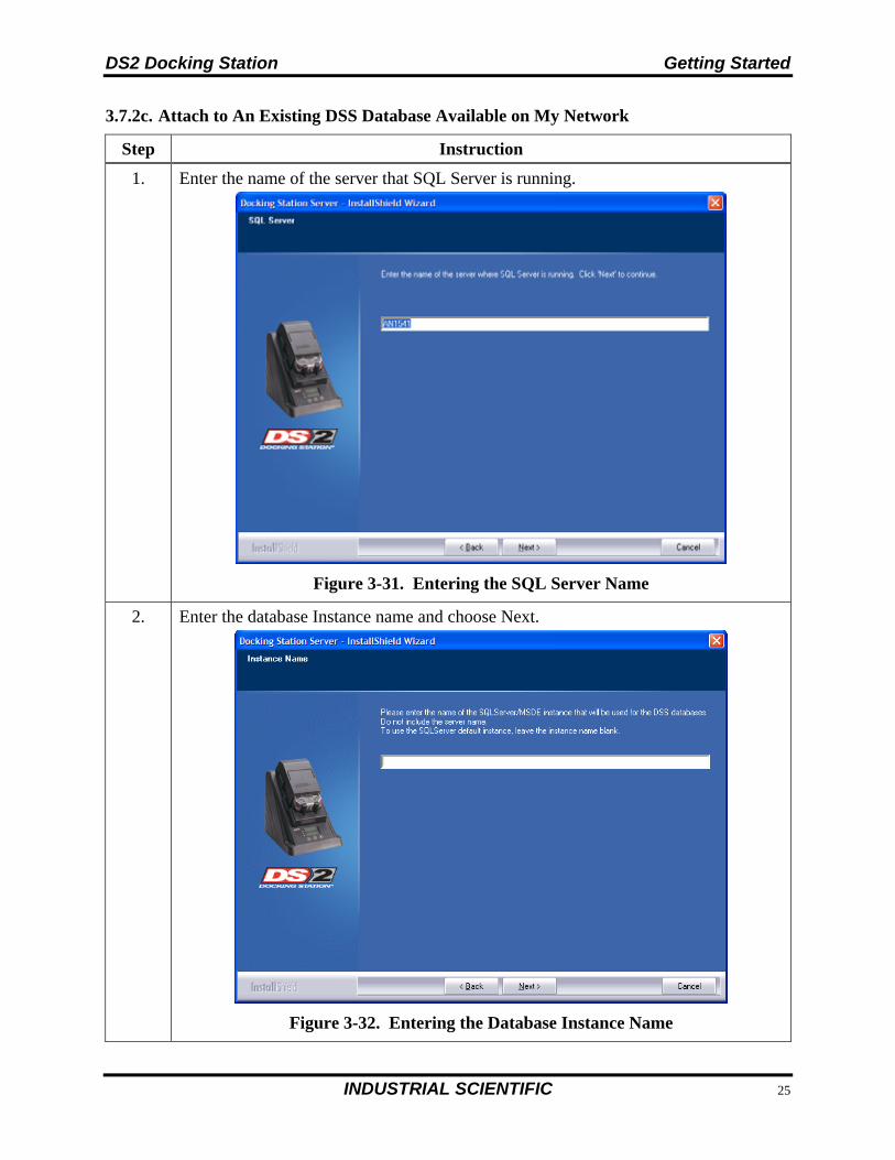
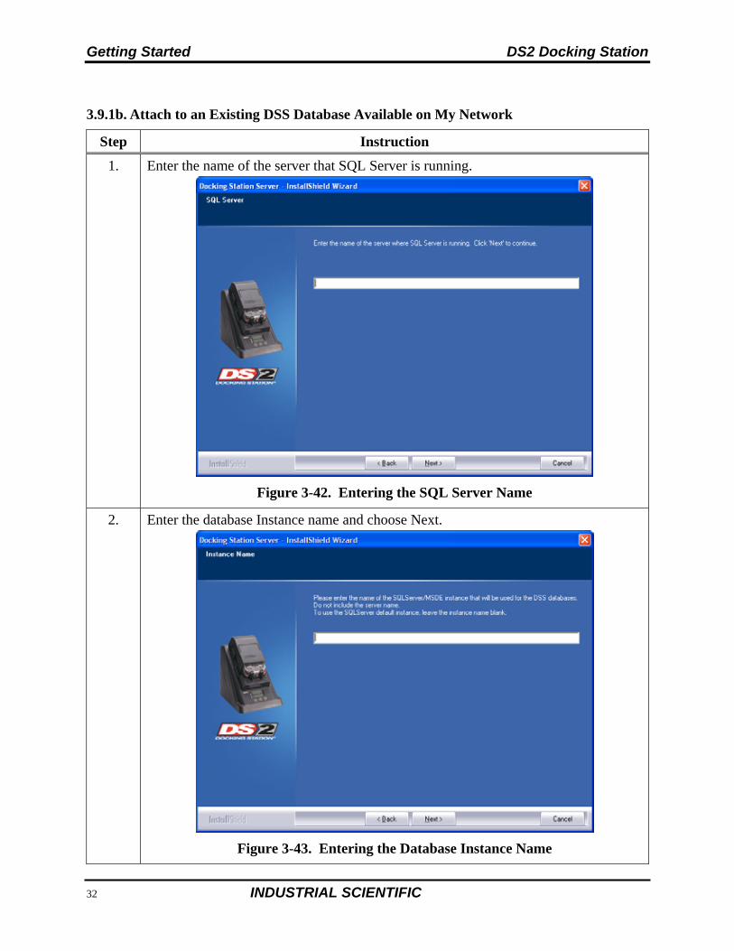
3.7.2c. Attach to An Existing DSS Database Available on My Network
Step Instruction
1. Enter the name of the server that SQL Server is running.
Figure 3-31. Entering the SQL Server Name
2. Enter the database Instance name and choose Next.
Figure 3-32. Entering the Database Instance Name
Getting Started DS2 Docking Station
48 INDUSTRIAL SCIENTIFIC
Step Instruction
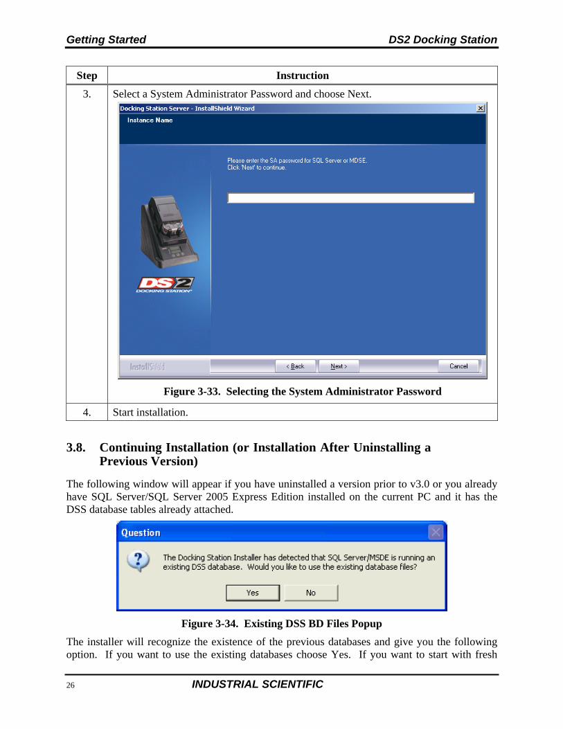
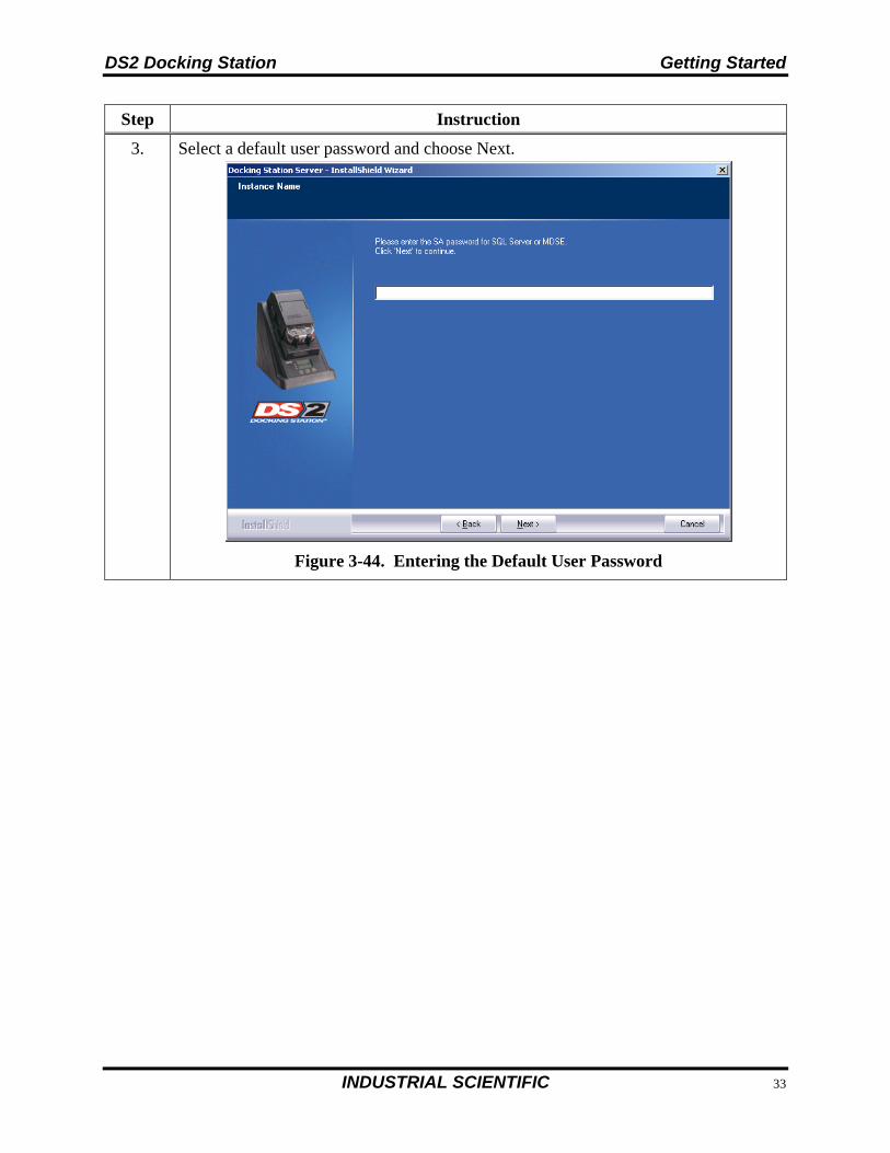
3. Select a System Administrator Password and choose Next.
Figure 3-33. Selecting the System Administrator Password
4. Start installation.
3.8. Continuing Installation (or Installation After Uninstalling a Previous Version)
The following window will appear if you have uninstalled a version prior to v3.0 or you already have SQL Server/SQL Server 2005 Express Edition installed on the current PC and it has the DSS database tables already attached.
Figure 3-34. Existing DSS BD Files Popup
The installer will recognize the existence of the previous databases and give you the following option. If you want to use the existing databases choose Yes. If you want to start with fresh
DS2 Docking Station Getting Started
INDUSTRIAL SCIENTIFIC 49
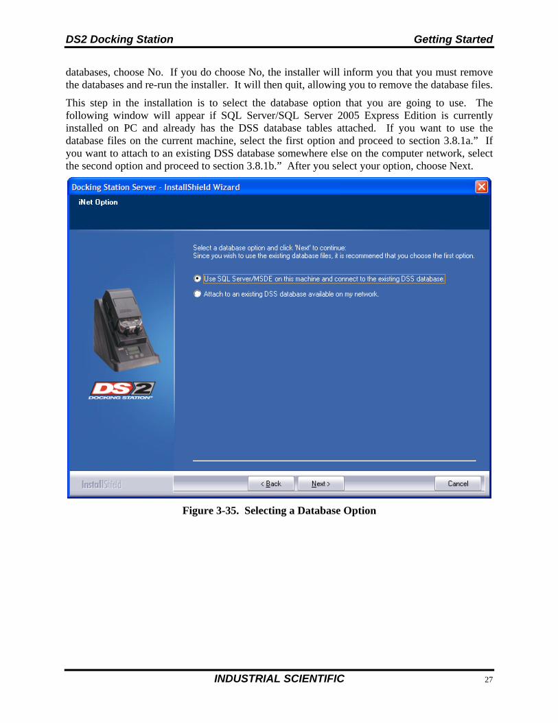
databases, choose No. If you do choose No, the installer will inform you that you must remove the databases and re-run the installer. It will then quit, allowing you to remove the database files.
This step in the installation is to select the database option that you are going to use. The following window will appear if SQL Server/SQL Server 2005 Express Edition is currently installed on PC and already has the DSS database tables attached. If you want to use the database files on the current machine, select the first option and proceed to section 3.8.1a.” If you want to attach to an existing DSS database somewhere else on the computer network, select the second option and proceed to section 3.8.1b.” After you select your option, choose Next.
Figure 3-35. Selecting a Database Option
Getting Started DS2 Docking Station
50 INDUSTRIAL SCIENTIFIC
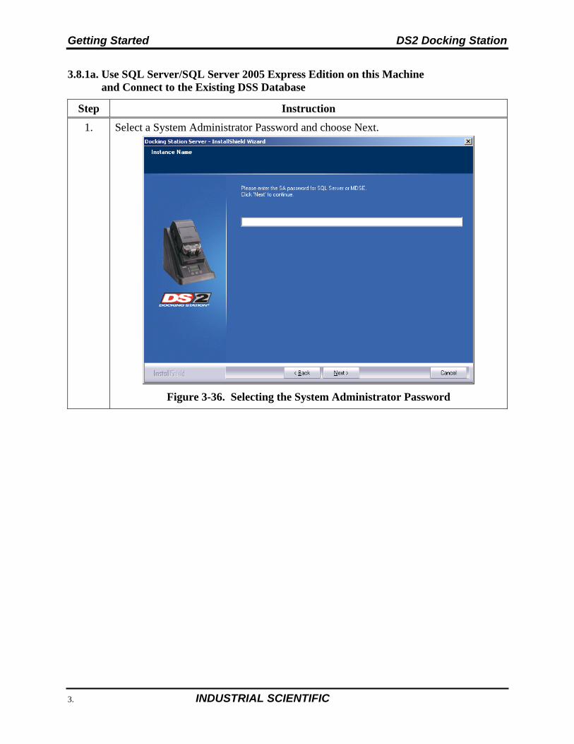
3.8.1a. Use SQL Server/SQL Server 2005 Express Edition on this Machine and Connect to the Existing DSS Database
Step Instruction
1. Select a System Administrator Password and choose Next.
Figure 3-36. Selecting the System Administrator Password
DS2 Docking Station Getting Started
INDUSTRIAL SCIENTIFIC 51
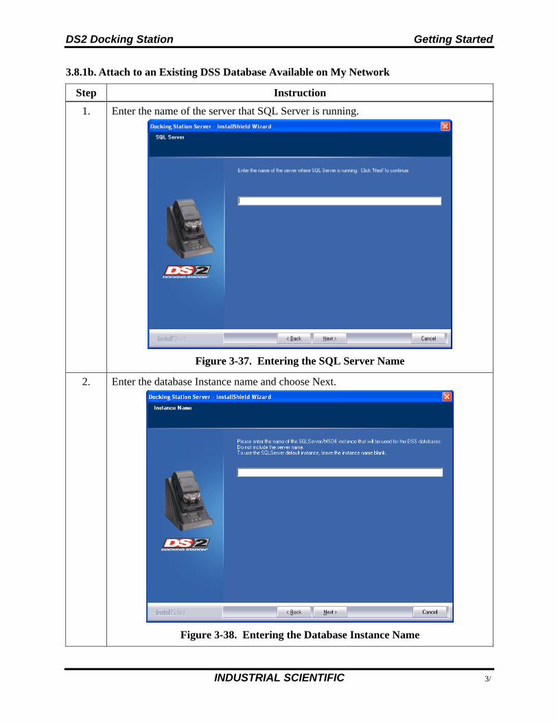
3.8.1b. Attach to an Existing DSS Database Available on My Network
Step Instruction
1. Enter the name of the server that SQL Server is running.
Figure 3-37. Entering the SQL Server Name
2. Enter the database Instance name and choose Next.
Figure 3-38. Entering the Database Instance Name
Getting Started DS2 Docking Station
52 INDUSTRIAL SCIENTIFIC
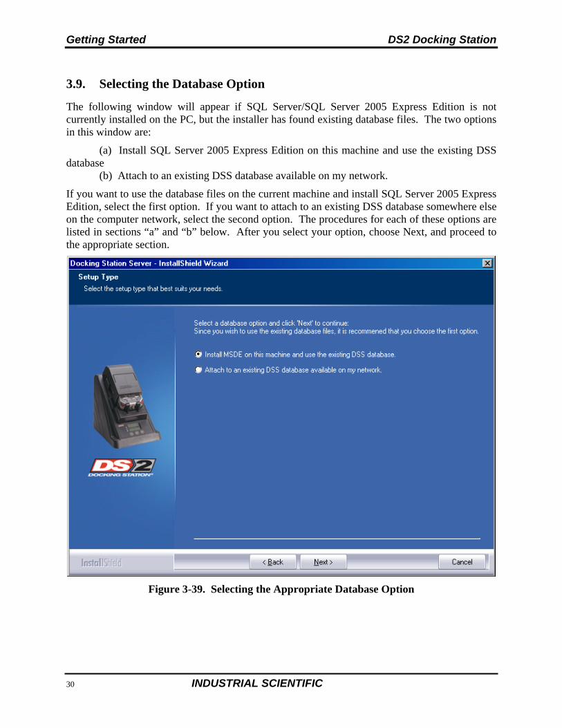
3.9. Selecting the Database Option
The following window will appear if SQL Server/SQL Server 2005 Express Edition is not currently installed on the PC, but the installer has found existing database files. The two options in this window are:
(a) Install SQL Server 2005 Express Edition on this machine and use the existing DSS database
(b) Attach to an existing DSS database available on my network.
If you want to use the database files on the current machine and install SQL Server 2005 Express Edition, select the first option. If you want to attach to an existing DSS database somewhere else on the computer network, select the second option. The procedures for each of these options are listed in sections “a” and “b” below. After you select your option, choose Next, and proceed to the appropriate section.
Figure 3-39. Selecting the Appropriate Database Option
DS2 Docking Station Getting Started
INDUSTRIAL SCIENTIFIC 53
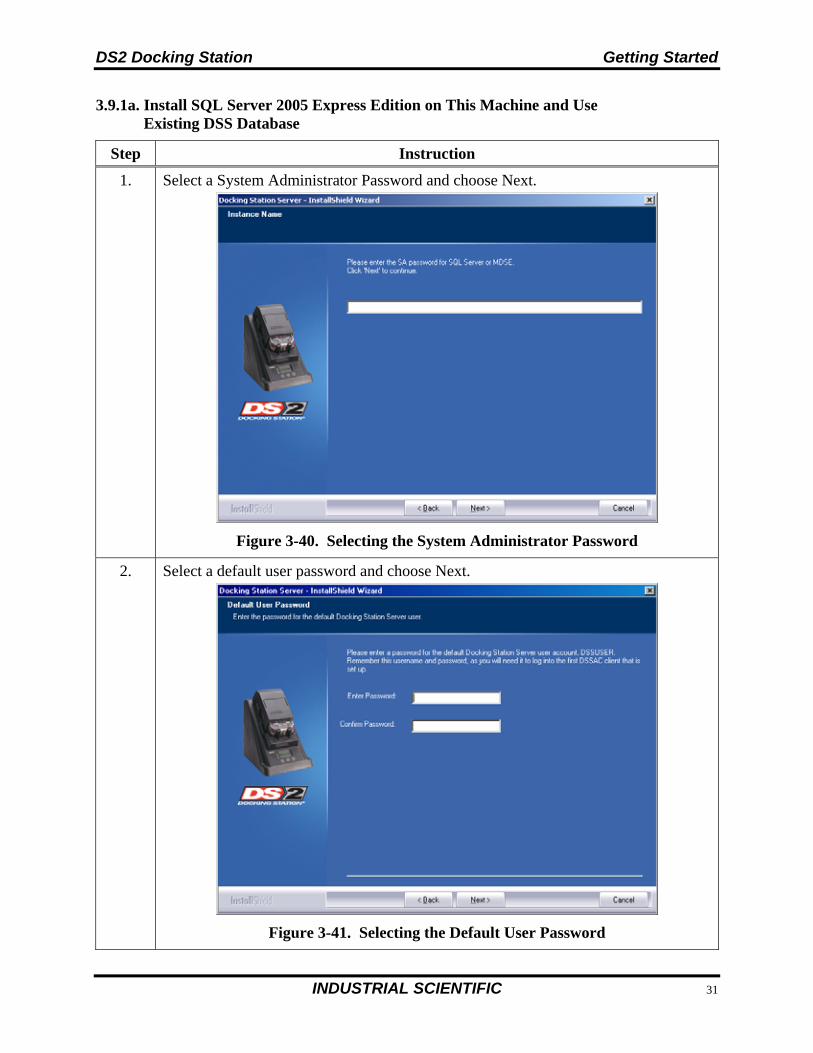
3.9.1a. Install SQL Server 2005 Express Edition on This Machine and Use Existing DSS Database
Step Instruction
1. Select a System Administrator Password and choose Next.
Figure 3-40. Selecting the System Administrator Password
2. Select a default user password and choose Next.
Figure 3-41. Selecting the Default User Password
Getting Started DS2 Docking Station
54 INDUSTRIAL SCIENTIFIC
3.9.1b. Attach to an Existing DSS Database Available on My Network
Step Instruction
1. Enter the name of the server that SQL Server is running.
Figure 3-42. Entering the SQL Server Name
2. Enter the database Instance name and choose Next.
Figure 3-43. Entering the Database Instance Name
DS2 Docking Station Getting Started
INDUSTRIAL SCIENTIFIC 55
Step Instruction
3. Select a default user password and choose Next.
Figure 3-44. Entering the Default User Password
Getting Started DS2 Docking Station
56 INDUSTRIAL SCIENTIFIC
3.10. iNet Considerations
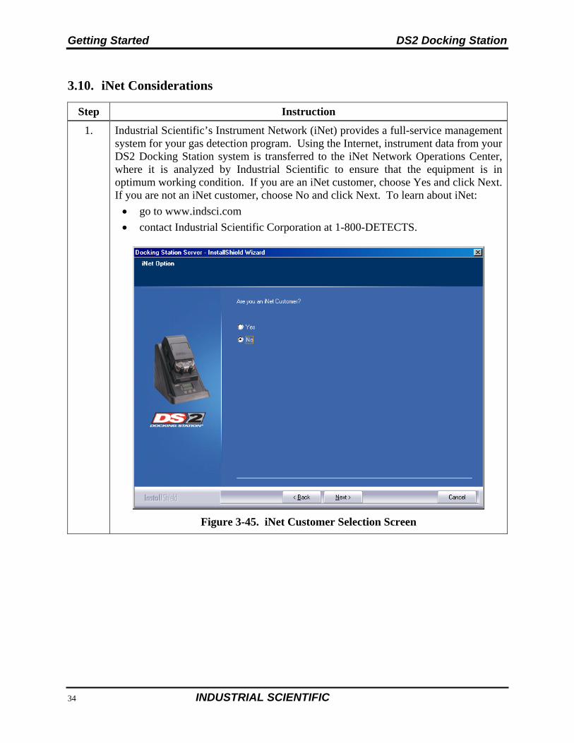
Step Instruction
1. Industrial Scientific’s Instrument Network (iNet) provides a full-service management system for your gas detection program. Using the Internet, instrument data from your DS2 Docking Station system is transferred to the iNet Network Operations Center, where it is analyzed by Industrial Scientific to ensure that the equipment is in optimum working condition. If you are an iNet customer, choose Yes and click Next. If you are not an iNet customer, choose No and click Next. To learn about iNet:
go to www.indsci.com
contact Industrial Scientific Corporation at 1-800-DETECTS.
Figure 3-45. iNet Customer Selection Screen
DS2 Docking Station Getting Started
INDUSTRIAL SCIENTIFIC 57
Step Instruction
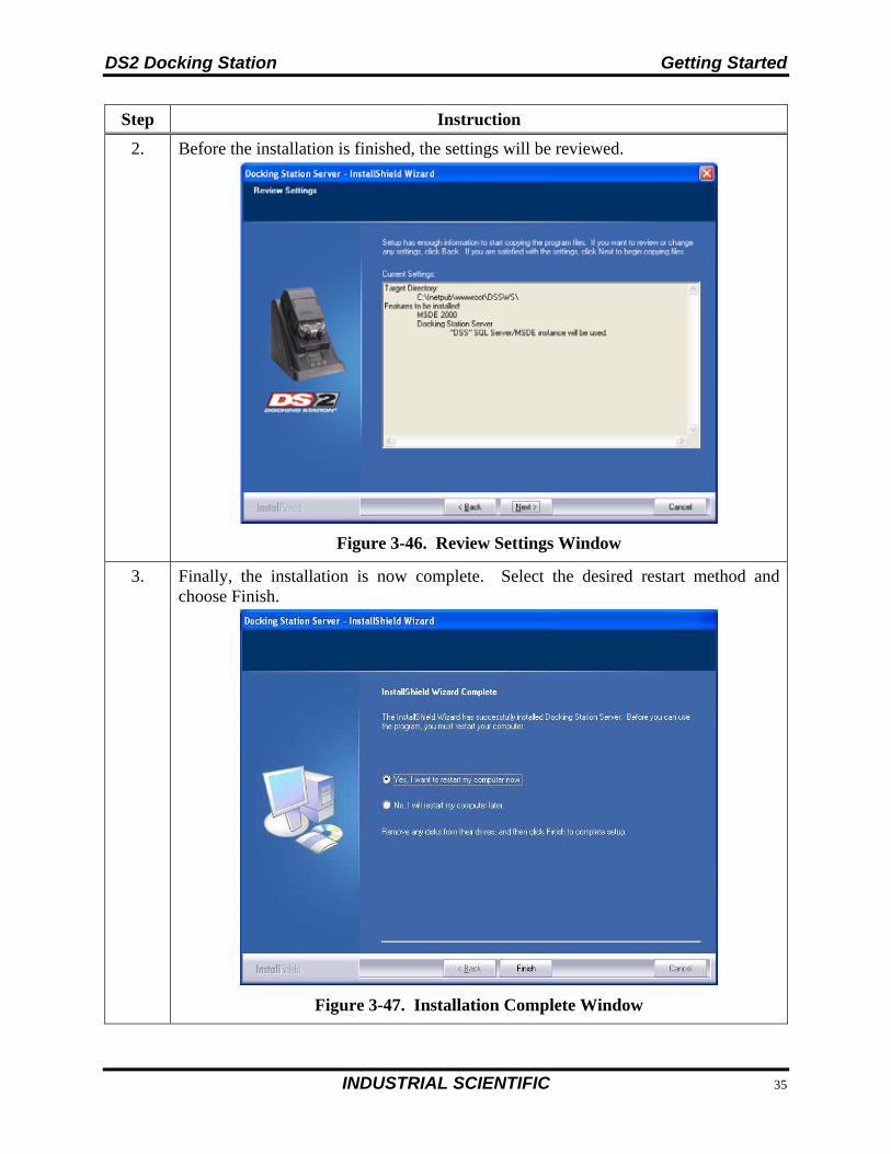
2. Before the installation is finished, the settings will be reviewed.
Figure 3-46. Review Settings Window
3. Finally, the installation is now complete. Select the desired restart method and choose Finish.
Figure 3-47. Installation Complete Window
Getting Started DS2 Docking Station
58 INDUSTRIAL SCIENTIFIC
Step Instruction
4. Installation of the DSS will also install and start the DS2 Broadcaster. The DS2 Broadcaster is a UDP broadcaster that will broadcast out the IP address of the PC or Server running the DSS such that all DS2s on the network will know which computer to communicate with. Industrial Scientific does not recommend turning off your DS2 Broadcaster unless you are running multiple DSSs on your network. It is the policy of some IT professionals not to have the DS2 Broadcaster running on a network. Therefore, the Broadcaster can be turned off.
5. If the DS2 Broadcaster is disabled, the DS2s will need to know the IP address of the server running the DSS. This is accomplished through using the DS2 Configurator Software. See section 3.12 on how to manually send out the IP address of the computer running the DSS.

DS2 Docking Station Getting Started
INDUSTRIAL SCIENTIFIC 59
3.11. Installing the DS2 Docking Station Server Admin Console (DSSAC) Software
NOTE: The following procedure is for the following Operating systems:
Windows 2000 Standard Server Windows 2003 Server Web Edition Windows 2000 Professional Windows XP Professional Windows Vista Windows 2008 Windows 7 Windows 8 Windows Server 2012
To begin the installation of the DSSAC software, follow the instructions below.
Step Instruction
1. Place the DS2 Operating CD into your computer.
2. The CD will automatically run and the following window will appear.
Figure 3-48. DS2 Docking Station Installation Window
3. Click on “Install Docking Station Server Admin Console.” This will automatically launch the DSSAC installer and sets the preferred language through the registry. The DSSAC can be installed on any computer on the network as well as the server or PC running the DSS software.
4. The software will guide you through the installation of the DSSAC.
Getting Started DS2 Docking Station
60 INDUSTRIAL SCIENTIFIC
3.12. The Docking Station Configurator
3.12.1. Installing the Docking Station Configurator Software
The Docking Station Configurator Software is a tool that can be used to send the IP address of the computer or server running the Docking Station Server Software (DSS) to a known DS2 IDS. If the DS2 Broadcaster service is turned off, or if a DS2 IDS is located on a different subnet than the computer or server running the DSS, then this software package must be used.
NOTE: The following procedure is for the following Operating systems:
Windows 2000 Standard Server Windows 2003 Server Web Edition Windows 2000 Professional Windows XP Professional. Windows Vista Windows 2008 Windows 7 Windows 8 Windows Server 2012
Step Instruction
5. Place the DS2 Operating CD into your computer.
6. The CD will automatically run and the following window will appear.
Figure 3-49. DS2 Docking Station Installation Window
7. Click on “Install Docking Station Configurator.” This will automatically launch the DS2 Configurator installer. The configurator software can be installed on any computer on the network as well as the server or PC running the DSS software.
DS2 Docking Station Getting Started
INDUSTRIAL SCIENTIFIC 61
3.12.2. Running the Docking Station Configurator Software
To run the Docking Station Configurator Software, follow the instructions below.
Step Instruction
8. Choose START / PROGRAMS / INDUSTRIAL SCIENTIFIC / DS2 CONFIGURATOR. The Docking Station Configurator screen is displayed.
Figure 3-50. Docking Station Configurator Screen
9. To tell the DS2 IDS what the IP address of the server is, select the Server IP Address tab, and then type in:
the IP address of the server the IP address of the DS2 and choose Send.
Figure 3-51. Server IP Address Tab
10. At this point, the DS2 IDS will automatically reboot.
Getting Started DS2 Docking Station
62 INDUSTRIAL SCIENTIFIC
3.13. Assigning a Static IP Address to a Sever or PC
Before assigning static IP addresses to the server or PC, consult with your Information Technology (IT) Department. If the server or PC on which the DSS software was installed already has a static IP address, then this section is not necessary. If the computer or server does not have a static IP address, then one must be assigned to it. This can be accomplished by using the following procedure.
Step Instruction
11. Any DS2 system should have a static IP address applied to the PC by a qualified IT person. Be sure to consult qualified personnel before proceeding.
12. Note that the following steps are used for reference only. They explain how to assign a static IP address to either a server or PC. Your actual process and data may vary.
13. Determine the current addressing on your PC.
Choose Start Choose Run Enter CMD Choose OK In the Command Prompt (DOS) window, type ipconfig Press ENTER
Figure 3-52. Using the IPCONFIG Command
Write down the three addresses for later use.
Item Address
IP Address . . .
Subnet Mask . . .
Default Gateway . . .
In the Command Prompt (DOS) window now type ipconfig /all.
Press ENTER.
Scroll down through all the text until you find the DNS Server address or addresses and record the DNS address. (There may be one or there may be two as seen here).
DS2 Docking Station Getting Started
INDUSTRIAL SCIENTIFIC 63
Step Instruction
Figure 3-53. DNS Server Results from IPCONFIG Command
DNS Server(s) Address(es)
#1 . . .
#2 (if applicable) . . .
Type exit and press ENTER to close this window.
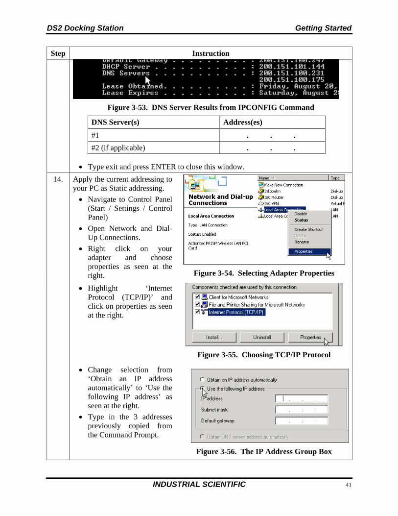
14. Apply the current addressing to your PC as Static addressing.
Navigate to Control Panel (Start / Settings / Control Panel)
Open Network and Dial-Up Connections.
Right click on your adapter and choose properties as seen at the right.
Figure 3-54. Selecting Adapter Properties
Highlight ‘Internet Protocol (TCP/IP)’ and click on properties as seen at the right.
Figure 3-55. Choosing TCP/IP Protocol
Change selection from ‘Obtain an IP address automatically’ to ‘Use the following IP address’ as seen at the right.
Type in the 3 addresses previously copied from the Command Prompt.
Figure 3-56. The IP Address Group Box
Getting Started DS2 Docking Station
64 INDUSTRIAL SCIENTIFIC
Step Instruction
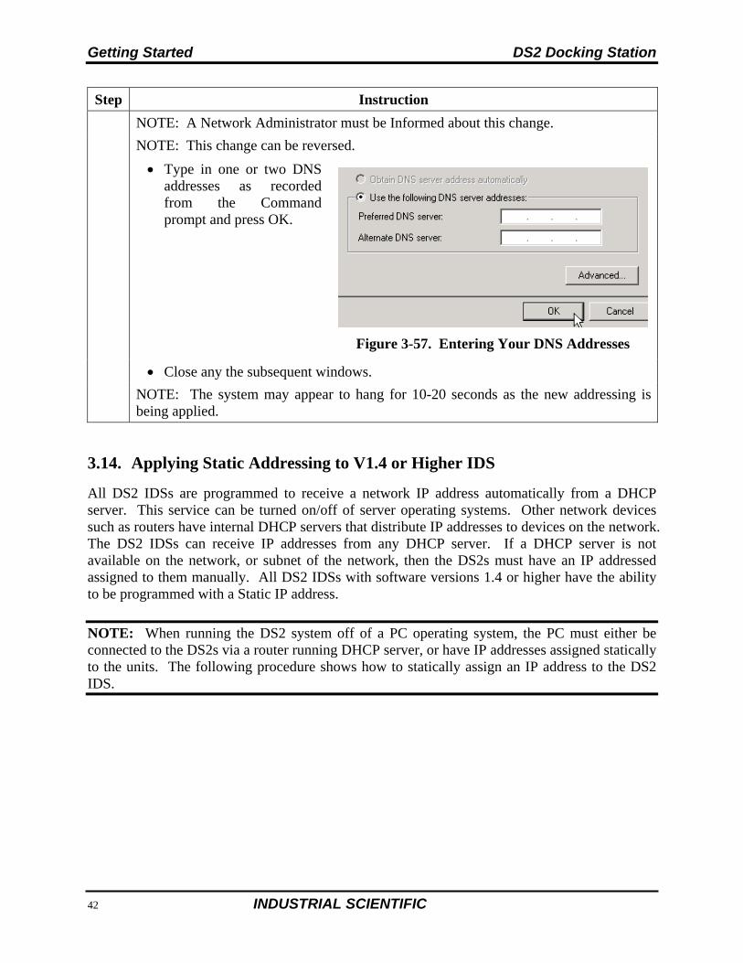
NOTE: A Network Administrator must be Informed about this change.
NOTE: This change can be reversed.
Type in one or two DNS addresses as recorded from the Command prompt and press OK.
Figure 3-57. Entering Your DNS Addresses
Close any the subsequent windows.
NOTE: The system may appear to hang for 10-20 seconds as the new addressing is being applied.
3.14. Applying Static Addressing to V1.4 or Higher IDS
All DS2 IDSs are programmed to receive a network IP address automatically from a DHCP server. This service can be turned on/off of server operating systems. Other network devices such as routers have internal DHCP servers that distribute IP addresses to devices on the network. The DS2 IDSs can receive IP addresses from any DHCP server. If a DHCP server is not available on the network, or subnet of the network, then the DS2s must have an IP addressed assigned to them manually. All DS2 IDSs with software versions 1.4 or higher have the ability to be programmed with a Static IP address.
NOTE: When running the DS2 system off of a PC operating system, the PC must either be connected to the DS2s via a router running DHCP server, or have IP addresses assigned statically to the units. The following procedure shows how to statically assign an IP address to the DS2 IDS.
DS2 Docking Station Getting Started
INDUSTRIAL SCIENTIFIC 65
Step Instruction
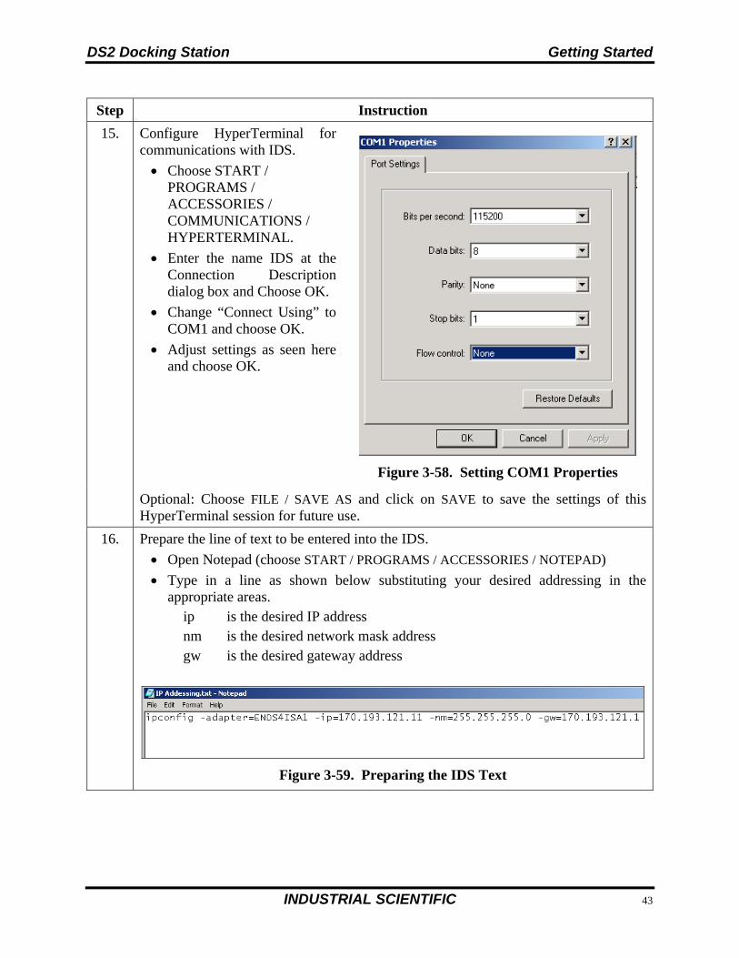
15. Configure HyperTerminal for communications with IDS.
Choose START / PROGRAMS / ACCESSORIES / COMMUNICATIONS / HYPERTERMINAL.
Enter the name IDS at the Connection Description dialog box and Choose OK.
Change “Connect Using” to COM1 and choose OK.
Adjust settings as seen here and choose OK.
Figure 3-58. Setting COM1 Properties
Optional: Choose FILE / SAVE AS and click on SAVE to save the settings of this HyperTerminal session for future use.
16. Prepare the line of text to be entered into the IDS.
Open Notepad (choose START / PROGRAMS / ACCESSORIES / NOTEPAD)
Type in a line as shown below substituting your desired addressing in the appropriate areas.
ip is the desired IP address nm is the desired network mask address gw is the desired gateway address
Figure 3-59. Preparing the IDS Text
Getting Started DS2 Docking Station
66 INDUSTRIAL SCIENTIFIC
Step Instruction
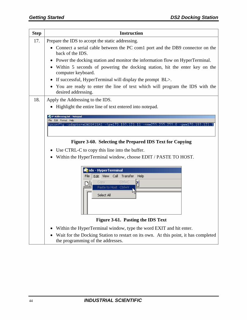
17. Prepare the IDS to accept the static addressing.
Connect a serial cable between the PC com1 port and the DB9 connector on the back of the IDS.
Power the docking station and monitor the information flow on HyperTerminal.
Within 5 seconds of powering the docking station, hit the enter key on the computer keyboard.
If successful, HyperTerminal will display the prompt BL>.
You are ready to enter the line of text which will program the IDS with the desired addressing.
18. Apply the Addressing to the IDS.
Highlight the entire line of text entered into notepad.
Figure 3-60. Selecting the Prepared IDS Text for Copying
Use CTRL-C to copy this line into the buffer.
Within the HyperTerminal window, choose EDIT / PASTE TO HOST.
Figure 3-61. Pasting the IDS Text
Within the HyperTerminal window, type the word EXIT and hit enter.
Wait for the Docking Station to restart on its own. At this point, it has completed the programming of the addresses.
DS2 Docking Station Getting Started
INDUSTRIAL SCIENTIFIC 67
3.15. Disabling the DS2 Broadcaster
NOTE: This portion of the installation process is only to be done if the policy of your Information Technology (IT) Department prohibits the broadcaster to be turned on.
The DS2 Broadcaster needs to be disabled if using the DSS on a LAN with other DSS installs. This step is not necessary for a production install of a DSS. This procedure is to accommodate users wishing to install DSS as a demo tool.
To disable the DS2 Broadcaster, follow the instructions below.
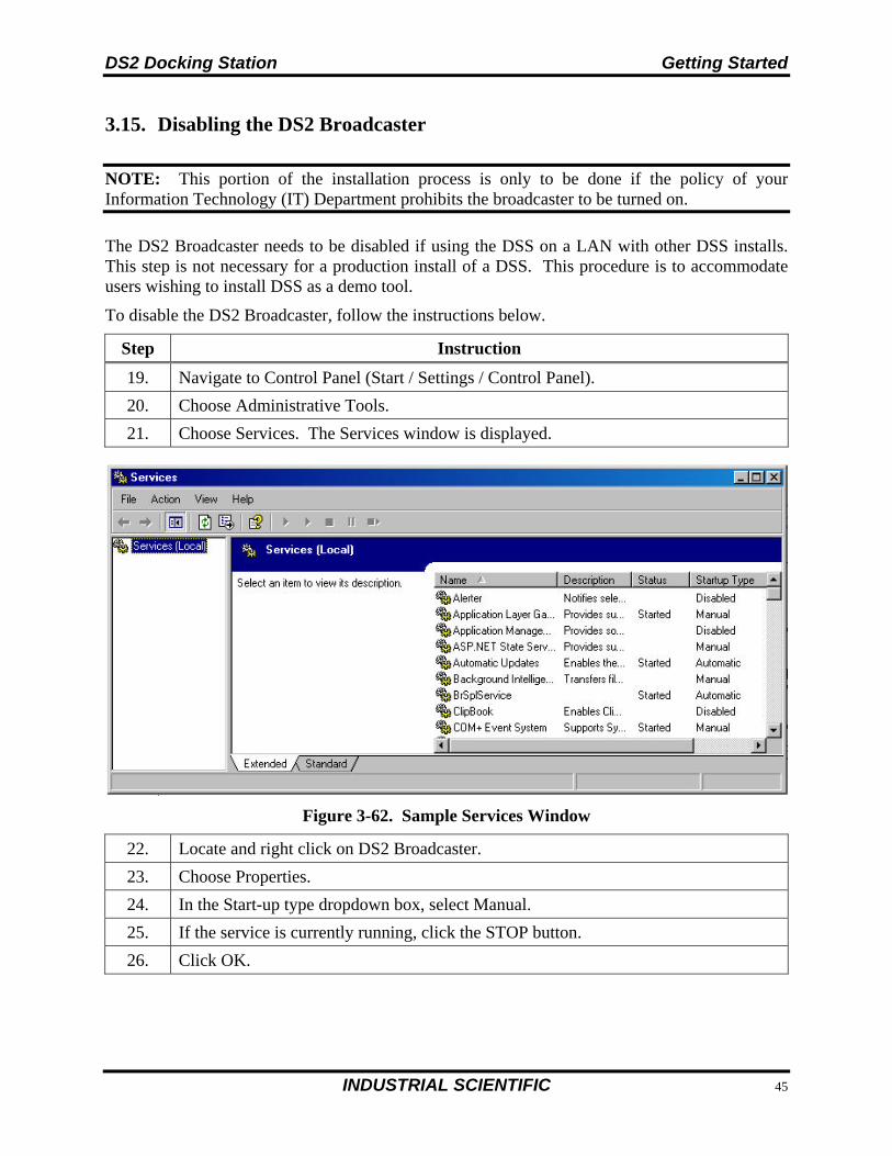
Step Instruction
19. Navigate to Control Panel (Start / Settings / Control Panel).
20. Choose Administrative Tools.
21. Choose Services. The Services window is displayed.
Figure 3-62. Sample Services Window
22. Locate and right click on DS2 Broadcaster.
23. Choose Properties.
24. In the Start-up type dropdown box, select Manual.
25. If the service is currently running, click the STOP button.
26. Click OK.
Getting Started DS2 Docking Station
68 INDUSTRIAL SCIENTIFIC
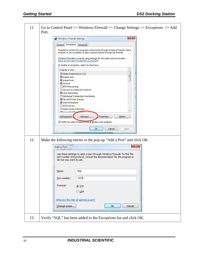
3.16. Configuring the Firewall
3.16.1. Windows XP Firewall
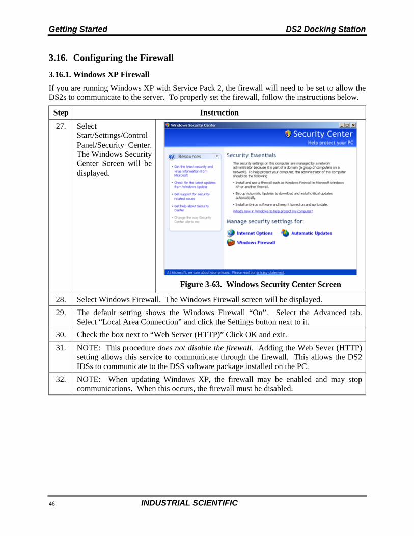
If you are running Windows XP with Service Pack 2, the firewall will need to be set to allow the DS2s to communicate to the server. To properly set the firewall, follow the instructions below.
Step Instruction
27. Select Start/Settings/Control Panel/Security Center. The Windows Security Center Screen will be displayed.
Figure 3-63. Windows Security Center Screen
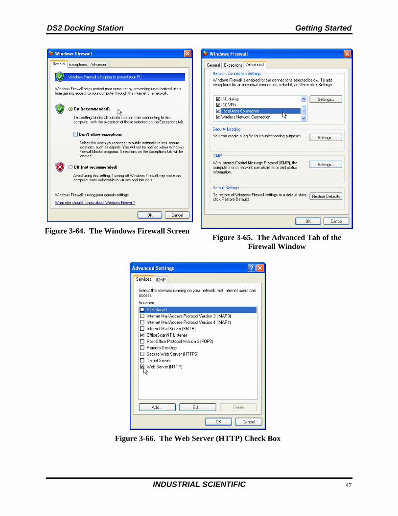
28. Select Windows Firewall. The Windows Firewall screen will be displayed.
29. The default setting shows the Windows Firewall “On”. Select the Advanced tab. Select “Local Area Connection” and click the Settings button next to it.
30. Check the box next to “Web Server (HTTP)” Click OK and exit.
31. NOTE: This procedure does not disable the firewall. Adding the Web Sever (HTTP) setting allows this service to communicate through the firewall. This allows the DS2 IDSs to communicate to the DSS software package installed on the PC.
32. NOTE: When updating Windows XP, the firewall may be enabled and may stop communications. When this occurs, the firewall must be disabled.
DS2 Docking Station Getting Started
INDUSTRIAL SCIENTIFIC 69
Figure 3-64. The Windows Firewall Screen
Figure 3-65. The Advanced Tab of the Firewall Window
Figure 3-66. The Web Server (HTTP) Check Box
Getting Started DS2 Docking Station
70 INDUSTRIAL SCIENTIFIC
3.16.2. Windows Firewall Settings for SQL Server
Step Instruction
NOTE: the user should be logged-on as an Administrator to perform the following tasks.
1. Make sure that “IIS_IUSRS” group has been provided the full access permissions for “C:\Windows\Temp” directory.
Navigate to C:\Windows.
Right-click on “Temp” directory and choose Properties.
In Security tab, make sure that IIS_IUSRS group has been listed. If not listed, click the “Modify” or “Edit” button; click the “Add” button and add “IIS_IUSRS”; and click the Resolve button on the right-hand side. Mark “Full Control” and click Apply and OK. It will give one warning message; click OK.
2. Enable Windows Firewall if it was disabled earlier.
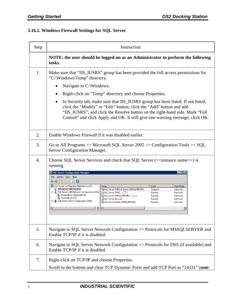
3. Go to All Programs >> Microsoft SQL Server 2005 >> Configuration Tools >> SQL Server Configuration Manager.
4. Choose SQL Server Services and check that SQL Server (<<instance name>>) is running.
5. Navigate to SQL Server Network Configuration >> Protocols for MSSQLSERVER and Enable TCP/IP if it is disabled.
6. Navigate to SQL Server Network Configuration >> Protocols for DSS (if available) and Enable TCP/IP if it is disabled.
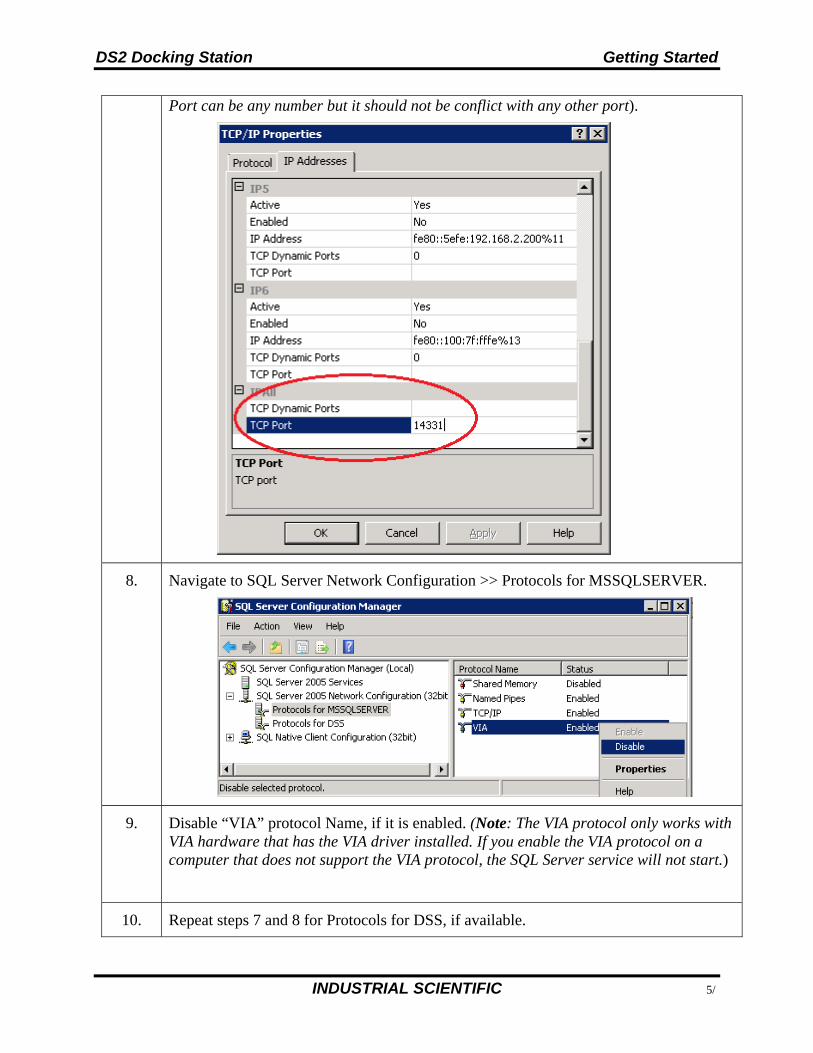
7. Right-click on TCP/IP and choose Properties.
Scroll to the bottom and clear TCP Dynamic Ports and add TCP Port as “14331” (note:
DS2 Docking Station Getting Started
INDUSTRIAL SCIENTIFIC 71
Port can be any number but it should not be conflict with any other port).
8. Navigate to SQL Server Network Configuration >> Protocols for MSSQLSERVER.
9. Disable “VIA” protocol Name, if it is enabled. (Note: The VIA protocol only works with VIA hardware that has the VIA driver installed. If you enable the VIA protocol on a computer that does not support the VIA protocol, the SQL Server service will not start.)
10. Repeat steps 7 and 8 for Protocols for DSS, if available.
Getting Started DS2 Docking Station
72 INDUSTRIAL SCIENTIFIC
11. Go to Control Panel >> Windows Firewall >> Change Settings >> Exceptions >> Add Port.
12. Make the following entries in the pop-up “Add a Port” and click OK.
13. Verify “SQL” has been added to the Exceptions list and click OK.
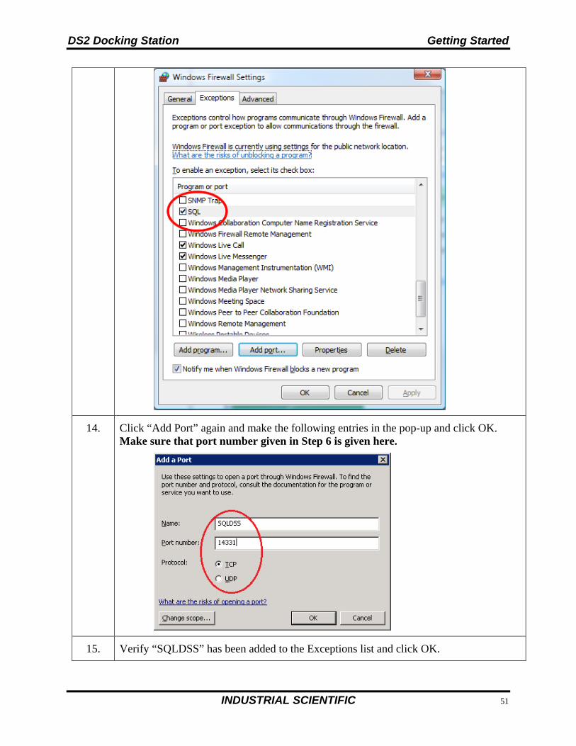
DS2 Docking Station Getting Started
INDUSTRIAL SCIENTIFIC 73
14. Click “Add Port” again and make the following entries in the pop-up and click OK. Make sure that port number given in Step 6 is given here.
15. Verify “SQLDSS” has been added to the Exceptions list and click OK.
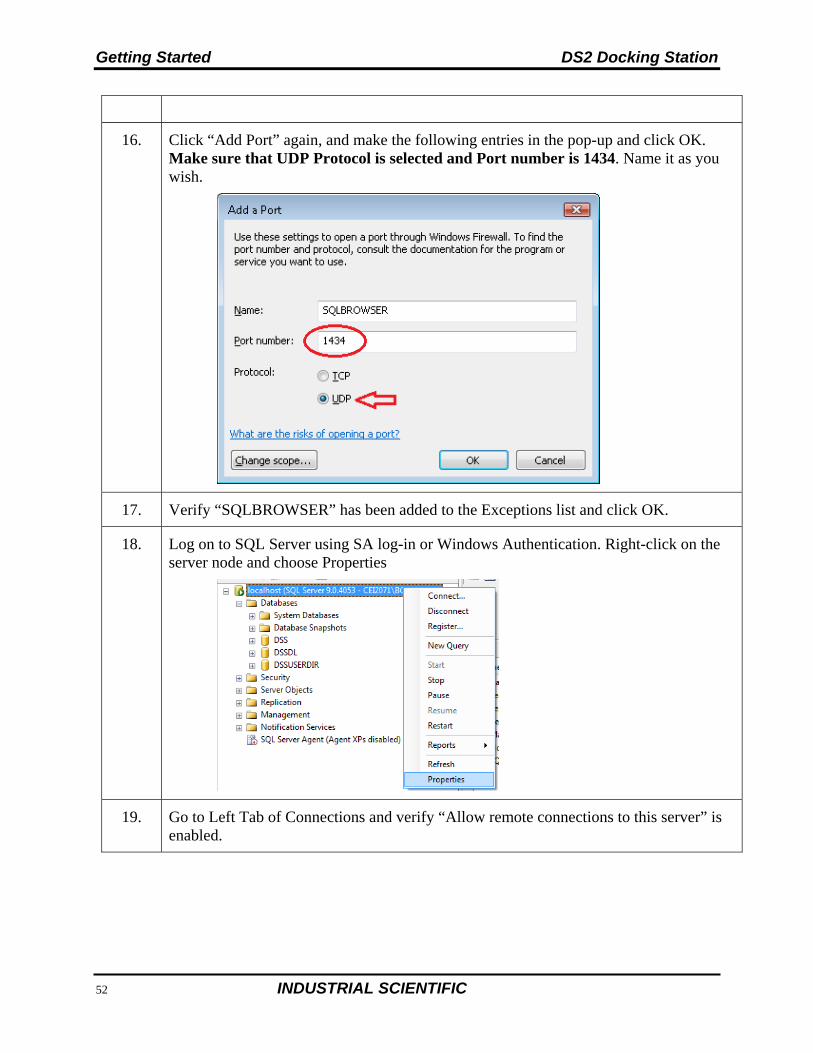
Getting Started DS2 Docking Station
74 INDUSTRIAL SCIENTIFIC
16. Click “Add Port” again, and make the following entries in the pop-up and click OK. Make sure that UDP Protocol is selected and Port number is 1434. Name it as you wish.
17. Verify “SQLBROWSER” has been added to the Exceptions list and click OK.
18. Log on to SQL Server using SA log-in or Windows Authentication. Right-click on the server node and choose Properties
19. Go to Left Tab of Connections and verify “Allow remote connections to this server” is enabled.
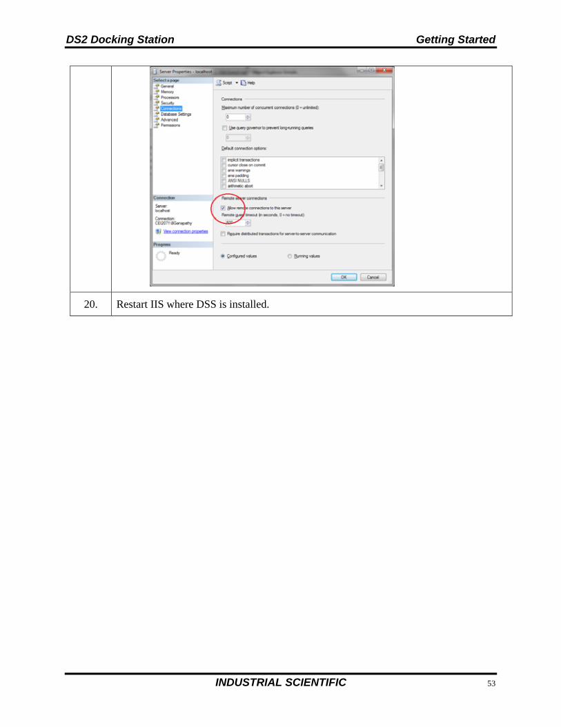
DS2 Docking Station Getting Started
INDUSTRIAL SCIENTIFIC 75
20. Restart IIS where DSS is installed.

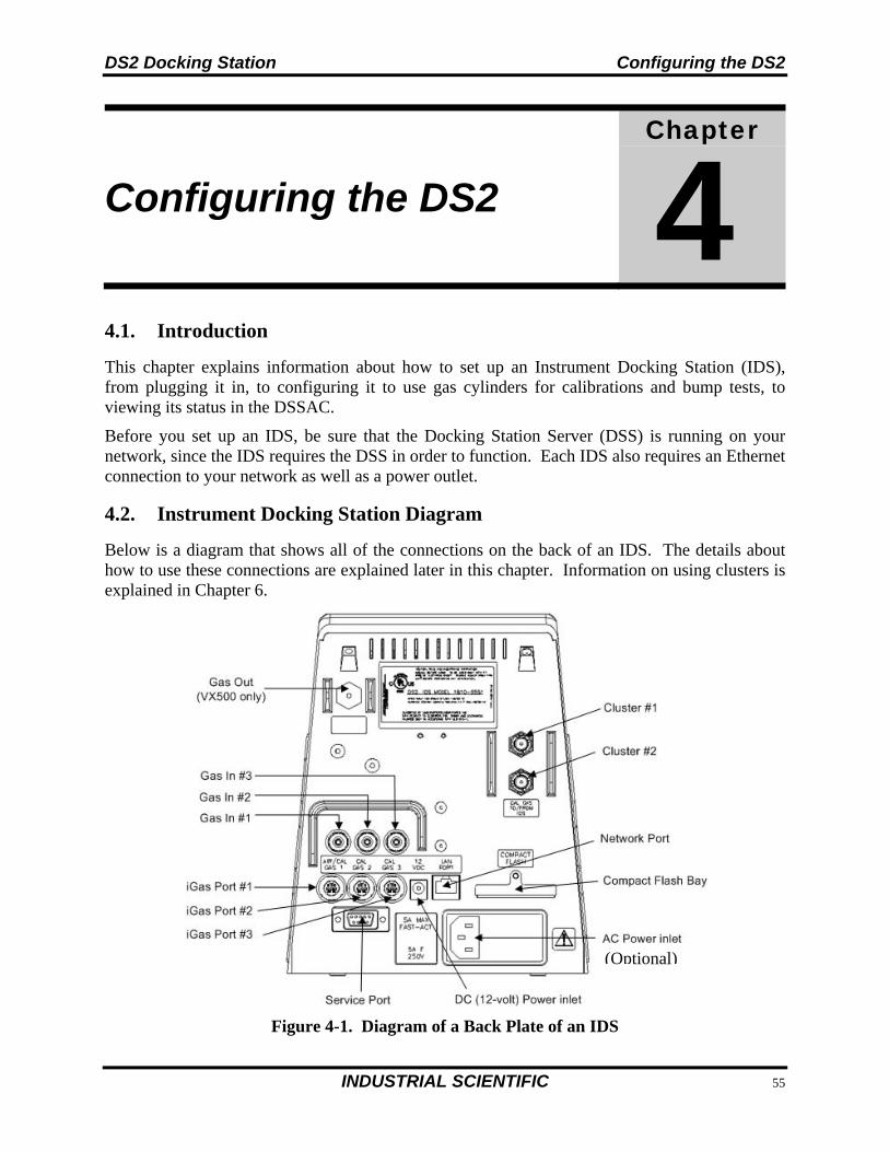
DS2 Docking Station Configuring the DS2
INDUSTRIAL SCIENTIFIC 77
Configuring the DS2
Chapter
4
4.1. Introduction
This chapter explains information about how to set up an Instrument Docking Station (IDS), from plugging it in, to configuring it to use gas cylinders for calibrations and bump tests, to viewing its status in the DSSAC.
Before you set up an IDS, be sure that the Docking Station Server (DSS) is running on your network, since the IDS requires the DSS in order to function. Each IDS also requires an Ethernet connection to your network as well as a power outlet.
4.2. Instrument Docking Station Diagram
Below is a diagram that shows all of the connections on the back of an IDS. The details about how to use these connections are explained later in this chapter. Information on using clusters is explained in Chapter 6.
Figure 4-1. Diagram of a Back Plate of an IDS
(Optional)
Configuring the DS2 DS2 Docking Station
78 INDUSTRIAL SCIENTIFIC
The table below briefly describes the connections on the back of an IDS.
Table 4-1. Connections on the Back of an IDS
Connection Description
Gas In #1, #2 and #3 Connects the IDS to calibration gas cylinders using gas tubing.
iGas Port #1, #2 and #3 If you are using iGas, these ports are used to connect the Smart Card reader to the IDS.
Service Port A serial port that is used by Industrial Scientific technicians to service the IDS.
DC (12-volt) Power Inlet Connects the IDS to a 12-volt power source.
AC Power Inlet Connects the IDS to an AC power source.
Compact Flash Bay A port used to accept Compact Flash cards. Compact Flash cards are used to upload future software updates to the Docking Station.
Network Port A standard Ethernet port to connect the IDS to your network.
Cluster #1 and #2 Gas connections that are used to cluster IDSs.
NOTE: Industrial Scientific recommends that gas tubing should be ester-based polyurethane type 85A.
The front of the IDS contains the cradle into which an instrument is docked. It also contains an LCD screen, a series of LED lights, and a keypad.
The LCD screen contains information about the activity of the IDS. The IDS contains three LED lights: red, yellow, and green. In general, if the red LED is illuminated, there is a problem with the IDS or the instrument that is currently docked. The yellow LED indicates that the IDS is busy performing a task, such as calibrating an instrument or downloading data. The green LED lights when the IDS is ready to receive instructions, either from the Docking Station Server, or from the IDS menu.
NOTE: Do not either dock or undock an instrument on the IDS when the yellow LED is illuminated, except when the instrument battery is charging.
Please refer to the LED and Alarm Signals section for more detail about the meanings of LED indicators, LCD messages, and alarm signals.

DS2 Docking Station Configuring the DS2
INDUSTRIAL SCIENTIFIC 79
Figure 4-2. Diagram of the Front Panel of an IDS
4.3. Setting Up an Instrument Docking Station
To prepare the IDS hardware for operation, follow the instructions listed below.
Step Instruction
1. Be sure that the Docking Station Server is running on your network, and that you have a connection to the network for the IDS.
2. Connect a network cable to the Network Port located on the back of the IDS. Plug the other end of the cable into a network connection on your network.
3. Plug the AC power cord to the AC Power inlet or the output cord from the DC power supply into the DC power inlet located on the back of the IDS. (The DS2 may alternatively be powered using a UL Listed I.T.E. power supply, supplied with the unit.)
4. Plug the power cord into a grounded wall outlet. The IDS automatically turns on when you plug it in.
NOTE: When the IDS is first plugged in, the three LEDs simultaneously flash. There is then a 40-second delay while the IDS boots. During the boot-up phase, the yellow LED is illuminated. When the IDS has completed booting, the backlight on the LCD panel turns on and the IDS emits a short beep.
Step Instruction
5. After the IDS has finished booting, the Docking Station Server automatically detects the IDS on the network. The LCD on the IDS displays “Discovering.” The yellow LED illuminates.
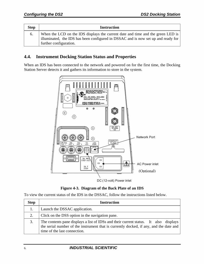
Configuring the DS2 DS2 Docking Station
80 INDUSTRIAL SCIENTIFIC
Step Instruction
6. When the LCD on the IDS displays the current date and time and the green LED is illuminated, the IDS has been configured in DSSAC and is now set up and ready for further configuration.
4.4. Instrument Docking Station Status and Properties
When an IDS has been connected to the network and powered on for the first time, the Docking Station Server detects it and gathers its information to store in the system.
Figure 4-3. Diagram of the Back Plate of an IDS
To view the current status of the IDS in the DSSAC, follow the instructions listed below.
Step Instruction
1. Launch the DSSAC application.
2. Click on the DSS option in the navigation pane.
3. The contents pane displays a list of IDSs and their current status. It also displays the serial number of the instrument that is currently docked, if any, and the date and time of the last connection.
(Optional)
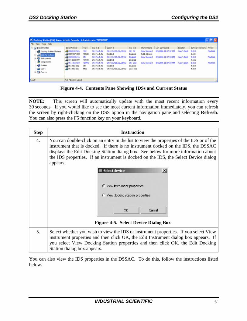
DS2 Docking Station Configuring the DS2
INDUSTRIAL SCIENTIFIC 81
Figure 4-4. Contents Pane Showing IDSs and Current Status
NOTE: This screen will automatically update with the most recent information every 30 seconds. If you would like to see the most current information immediately, you can refresh the screen by right-clicking on the DSS option in the navigation pane and selecting Refresh. You can also press the F5 function key on your keyboard.
Step Instruction
4. You can double-click on an entry in the list to view the properties of the IDS or of the instrument that is docked. If there is no instrument docked on the IDS, the DSSAC displays the Edit Docking Station dialog box. See below for more information about the IDS properties. If an instrument is docked on the IDS, the Select Device dialog appears.
Figure 4-5. Select Device Dialog Box
5. Select whether you wish to view the IDS or instrument properties. If you select View instrument properties and then click OK, the Edit Instrument dialog box appears. If you select View Docking Station properties and then click OK, the Edit Docking Station dialog box appears.
You can also view the IDS properties in the DSSAC. To do this, follow the instructions listed below.
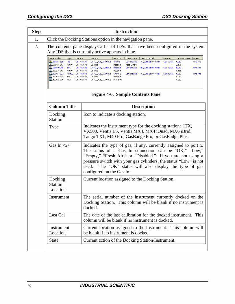
Configuring the DS2 DS2 Docking Station
82 INDUSTRIAL SCIENTIFIC
Step Instruction
1. Click the Docking Stations option in the navigation pane.
2. The contents pane displays a list of IDSs that have been configured in the system. Any IDS that is currently active appears in blue.
Figure 4-6. Sample Contents Pane
Column Title Description
Docking Station
Icon to indicate a docking station.
Type Indicates the instrument type for the docking station: ITX, VX500, Ventis LS, Ventis MX4, MX4 iQuad, MX6 iBrid, Tango TX1, M40 Pro, GasBadge Pro, or GasBadge Plus.
Gas In <x> Indicates the type of gas, if any, currently assigned to port x. The status of a Gas In connection can be “OK,” “Low,” “Empty,” “Fresh Air,” or “Disabled.” If you are not using a pressure switch with your gas cylinders, the status “Low” is not used. The “OK” status will also display the type of gas configured on the Gas In.
Docking Station Location
Current location assigned to the Docking Station.
Instrument The serial number of the instrument currently docked on the Docking Station. This column will be blank if no instrument is docked.
Last Cal The date of the last calibration for the docked instrument. This column will be blank if no instrument is docked.
Instrument Location
Current location assigned to the Instrument. This column will be blank if no instrument is docked.
State Current action of the Docking Station/Instrument.
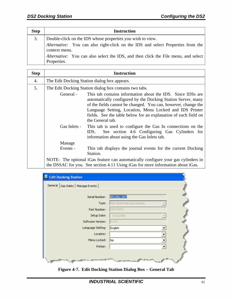
DS2 Docking Station Configuring the DS2
INDUSTRIAL SCIENTIFIC 83
Step Instruction
3. Double-click on the IDS whose properties you wish to view. Alternative: You can also right-click on the IDS and select Properties from the context menu. Alternative: You can also select the IDS, and then click the File menu, and select Properties.
Step Instruction
4. The Edit Docking Station dialog box appears.
5. The Edit Docking Station dialog box contains two tabs. General - This tab contains information about the IDS. Since IDSs are
automatically configured by the Docking Station Server, many of the fields cannot be changed. You can, however, change the Language Setting, Location, Menu Locked and IDS Printer fields. See the table below for an explanation of each field on the General tab.
Gas Inlets - This tab is used to configure the Gas In connections on the IDS. See section 4.6 Configuring Gas Cylinders for information about using the Gas Inlets tab.
Manage Events - This tab displays the journal events for the current Docking
Station. NOTE: The optional iGas feature can automatically configure your gas cylinders in the DSSAC for you. See section 4.11 Using iGas for more information about iGas.
Figure 4-7. Edit Docking Station Dialog Box – General Tab
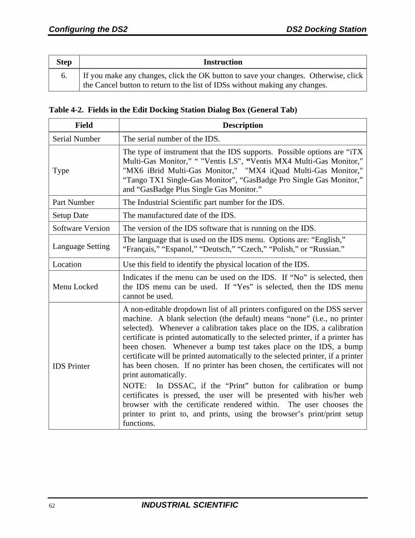
Configuring the DS2 DS2 Docking Station
84 INDUSTRIAL SCIENTIFIC
Step Instruction
6. If you make any changes, click the OK button to save your changes. Otherwise, click the Cancel button to return to the list of IDSs without making any changes.
Table 4-2. Fields in the Edit Docking Station Dialog Box (General Tab)
Field Description
Serial Number The serial number of the IDS.
Type
The type of instrument that the IDS supports. Possible options are “iTX Multi-Gas Monitor,” “ "Ventis LS", “Ventis MX4 Multi-Gas Monitor," "MX6 iBrid Multi-Gas Monitor," "MX4 iQuad Multi-Gas Monitor," “Tango TX1 Single-Gas Monitor”, “GasBadge Pro Single Gas Monitor,” and “GasBadge Plus Single Gas Monitor.”
Part Number The Industrial Scientific part number for the IDS.
Setup Date The manufactured date of the IDS.
Software Version The version of the IDS software that is running on the IDS.
Language Setting The language that is used on the IDS menu. Options are: “English,” “Français,” “Espanol,” “Deutsch,” “Czech,” “Polish,” or “Russian.”
Location Use this field to identify the physical location of the IDS.
Menu Locked Indicates if the menu can be used on the IDS. If “No” is selected, then the IDS menu can be used. If “Yes” is selected, then the IDS menu cannot be used.
IDS Printer
A non-editable dropdown list of all printers configured on the DSS server machine. A blank selection (the default) means “none” (i.e., no printer selected). Whenever a calibration takes place on the IDS, a calibration certificate is printed automatically to the selected printer, if a printer has been chosen. Whenever a bump test takes place on the IDS, a bump certificate will be printed automatically to the selected printer, if a printer has been chosen. If no printer has been chosen, the certificates will not print automatically. NOTE: In DSSAC, if the “Print” button for calibration or bump certificates is pressed, the user will be presented with his/her web browser with the certificate rendered within. The user chooses the printer to print to, and prints, using the browser’s print/print setup functions.
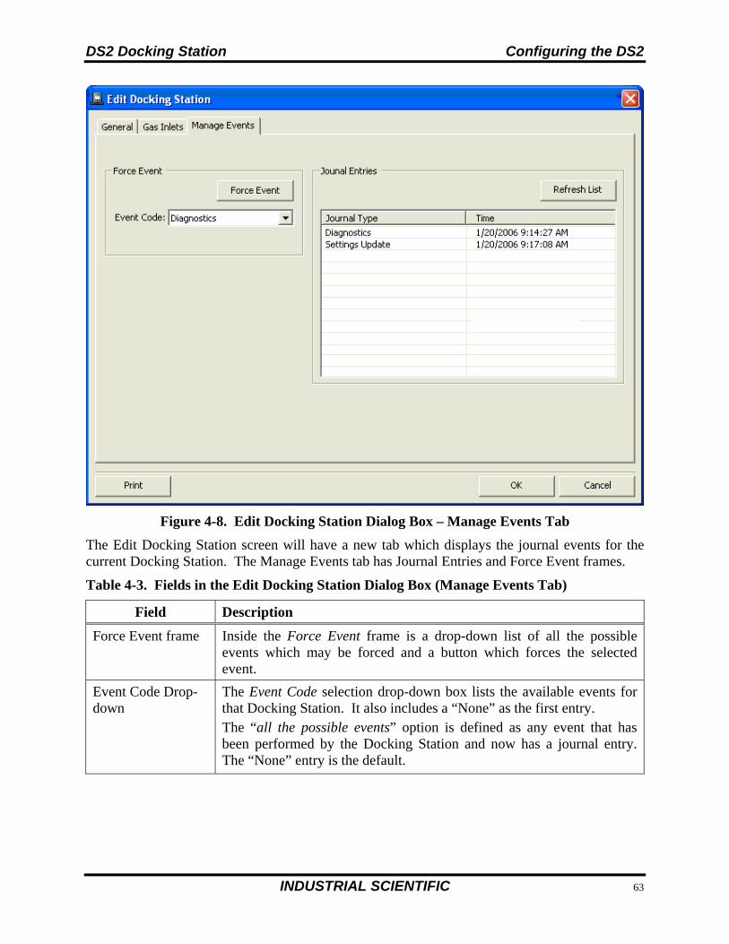
DS2 Docking Station Configuring the DS2
INDUSTRIAL SCIENTIFIC 85
Figure 4-8. Edit Docking Station Dialog Box – Manage Events Tab
The Edit Docking Station screen will have a new tab which displays the journal events for the current Docking Station. The Manage Events tab has Journal Entries and Force Event frames.
Table 4-3. Fields in the Edit Docking Station Dialog Box (Manage Events Tab)
Field Description
Force Event frame Inside the Force Event frame is a drop-down list of all the possible events which may be forced and a button which forces the selected event.
Event Code Drop-down
The Event Code selection drop-down box lists the available events for that Docking Station. It also includes a “None” as the first entry. The “all the possible events” option is defined as any event that has been performed by the Docking Station and now has a journal entry. The “None” entry is the default.
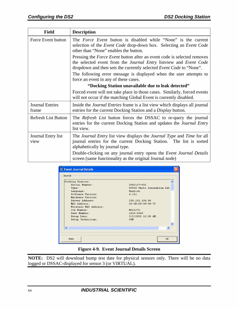
Configuring the DS2 DS2 Docking Station
86 INDUSTRIAL SCIENTIFIC
Field Description
Force Event button The Force Event button is disabled while “None” is the current selection of the Event Code drop-down box. Selecting an Event Code other than “None” enables the button. Pressing the Force Event button after an event code is selected removes the selected event from the Journal Entry listview and Event Code dropdown and then sets the currently selected Event Code to “None”. The following error message is displayed when the user attempts to force an event in any of these cases.
“Docking Station unavailable due to leak detected” Forced event will not take place in those cases. Similarly, forced events will not occur if the matching Global Event is currently disabled.
Journal Entries frame
Inside the Journal Entries frame is a list view which displays all journal entries for the current Docking Station and a Display button.
Refresh List Button The Refresh List button forces the DSSAC to re-query the journal entries for the current Docking Station and updates the Journal Entry list view.
Journal Entry list view
The Journal Entry list view displays the Journal Type and Time for all journal entries for the current Docking Station. The list is sorted alphabetically by journal type. Double-clicking on any journal entry opens the Event Journal Details screen (same functionality as the original Journal node)
Figure 4-9. Event Journal Details Screen
NOTE: DS2 will download bump test date for physical sensors only. There will be no data logged or DSSAC-displayed for sensor 3 (or VIRTUAL).
DS2 Docking Station Configuring the DS2
INDUSTRIAL SCIENTIFIC 87
4.5. Removing an Instrument Docking Station
You can remove an IDS from the DSSAC. However, the next time that the IDS is connected to the network, the Docking Station Server detects it and adds it back into the list of IDSs in the DSSAC.
You may need to remove an IDS if it is no longer in use or it is being moved to another Docking Station Network.
To remove an IDS, follow the instructions listed below.
Step Instruction
1. Launch the DSSAC application.
2. Click the Docking Stations option in the navigation pane.
3. Select the IDS that you wish to remove. You can select multiple IDSs by pressing the CTRL key on your keyboard while clicking on each IDS.
4. Click on the File menu and select Remove. Alternative: You can also right click on the selected IDS(s) and select Remove from the drop-down menu.
5. A confirmation prompt appears. Click Yes to remove the IDS(s). Click No to cancel the removal.
4.6. Configuring Gas Cylinders
In order to perform calibrations and bump tests using DS2 Docking Station, the IDS Gas In connections must be configured to use gas cylinders. Configuring gas cylinders involves two steps: (1) setting up the physical hardware, i.e., the IDS and cylinders, and (2) configuring the Gas In connection in the DSSAC.
Each IDS has three Gas In connections that are used to connect to gas cylinders. One of these Gas In connections should be configured to use fresh air or a Zero Air gas cylinder that is used to purge the gas lines between calibrations or bump tests using different types of gases. A Zero Air gas cylinder should always be used if there is a potential for interference from background gases, or if the atmosphere is dirty.
DS2 Docking Station requires that a demand flow regulator be used on calibration gas cylinders that are connected to an IDS.
NOTE: You can increase the number of gases available for calibration by clustering your IDSs. See Chapter 6 for more information about clustering IDSs.
NOTE: If you are using iGas, you do not need to follow the instructions below. Please refer to section 4.11 Using iGas.
Configuring the DS2 DS2 Docking Station
88 INDUSTRIAL SCIENTIFIC
CAUTION: Compressed gas cylinders and their contents may present specific hazards to the user. Use only in a well-ventilated area. Use only in accordance with the instructions and warnings marked on the cylinder and the appropriate Material Safety Data Sheets.
To configure an IDS Gas In connection to use calibration gas, follow the instructions below.
Step Instruction
1. Connect the demand flow regulator to the gas cylinder. With the gauge facing away from you, place the regulator on top of the cylinder and turn the cylinder until it is connected tightly.
2. Disconnect the supplied Luer fittings from the Gas In connection that you wish to use.
3. Connect one end of a piece of polyurethane gas tubing to the fitting on the demand flow regulator. Connect the Luer fitting to the other end of the tubing, and then attach the fitting to the Gas In connection in the back of the IDS.
NOTE: For Chlorine (Cl2), Ammonia (NH3) and Hydrogen Chloride (HCl) gases, the gas tube length should not exceed three (3) feet.
NOTE: Industrial Scientific recommends that gas tubing should be ester-based polyurethane type 85A.
Step Instruction
4. Launch the DSSAC application. Click the Docking Stations option in the navigation pane.
5. Double-click on the IDS whose Gas In connections you wish to configure. Alternative: You can also right-click on the IDS and select Properties from the context menu. Alternative: You can also select the IDS, and then click the File menu, and select Properties.
6. The Edit Docking Station dialog box appears. Click on the Gas Inlets tab. The Gas Inlets tab contains three (3) tabs, one for each Gas In connection on the IDS.
NOTE: Each Gas In tab contains an icon to identify the status of the connection. See the Table 4-4 for a description of each of the icons.
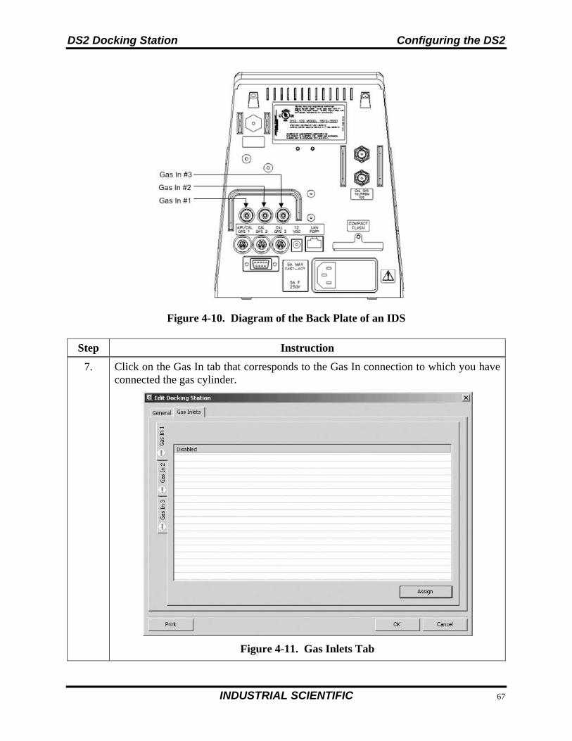
DS2 Docking Station Configuring the DS2
INDUSTRIAL SCIENTIFIC 89
Figure 4-10. Diagram of the Back Plate of an IDS
Step Instruction
7. Click on the Gas In tab that corresponds to the Gas In connection to which you have connected the gas cylinder.
Figure 4-11. Gas Inlets Tab
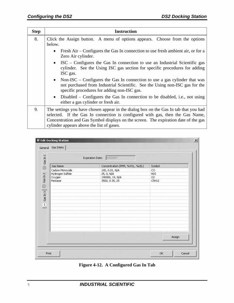
Configuring the DS2 DS2 Docking Station
90 INDUSTRIAL SCIENTIFIC
Step Instruction
8. Click the Assign button. A menu of options appears. Choose from the options below.
Fresh Air – Configures the Gas In connection to use fresh ambient air, or for a Zero Air cylinder.
ISC – Configures the Gas In connection to use an Industrial Scientific gas cylinder. See the Using ISC gas section for specific procedures for adding ISC gas.
Non-ISC – Configures the Gas In connection to use a gas cylinder that was not purchased from Industrial Scientific. See the Using non-ISC gas for the specific procedures for adding non-ISC gas.
Disabled – Configures the Gas In connection to be disabled, i.e., not using either a gas cylinder or fresh air.
9. The settings you have chosen appear in the dialog box on the Gas In tab that you had selected. If the Gas In connection is configured with gas, then the Gas Name, Concentration and Gas Symbol displays on the screen. The expiration date of the gas cylinder appears above the list of gases.
Figure 4-12. A Configured Gas In Tab
DS2 Docking Station Configuring the DS2
INDUSTRIAL SCIENTIFIC 91
Step Instruction
10. Click the OK button from the Edit Docking Station dialog box to save your changes.
11. The gas cylinder is now ready to be used.
CAUTION: When configuring Gas In connections, be careful that you have configured the correct gas type in the DSSAC that matches the gas type in the cylinder connected to the Gas In connection on the IDS. If this setup is incorrect, your calibrations may be run with the incorrect gas, rendering the results inaccurate.
Table 4-4. Gas Inlets Tab Icons
Icon Description Explanation
Solid Green Circle The cylinder is ok or is using fresh air.
Solid Yellow Circle The cylinder is low.
Solid Red Circle The cylinder is empty.
Red Circle with a White X The cylinder is expired.
Yellow Circle with an exclamation point
The Gas In connection is disabled.
NOTE: If you hover your mouse pointer over one of the icons on the Gas Inlets tab, the status of the cylinder or Gas In connection displays.
4.7. Adding Gas from Industrial Scientific
To add an ISC gas, follow the instructions below.
Step Instruction
1. From the Edit Docking Station dialog box, click on the Gas Inlets tab.
2. Select the tab corresponding to the Gas In connection that you are configuring.
3. Click the Assign button and select ISC.
4. The Cylinder Configuration dialog box appears.
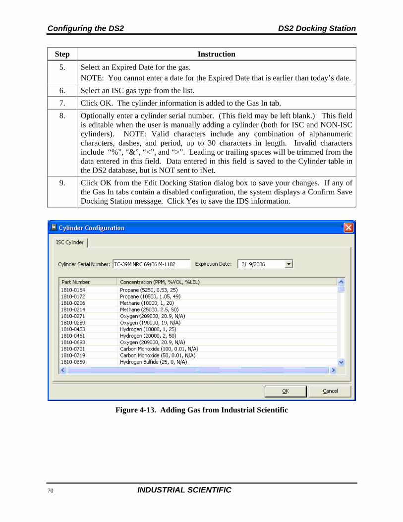
Configuring the DS2 DS2 Docking Station
92 INDUSTRIAL SCIENTIFIC
Step Instruction
5. Select an Expired Date for the gas. NOTE: You cannot enter a date for the Expired Date that is earlier than today’s date.
6. Select an ISC gas type from the list.
7. Click OK. The cylinder information is added to the Gas In tab.
8. Optionally enter a cylinder serial number. (This field may be left blank.) This field is editable when the user is manually adding a cylinder (both for ISC and NON-ISC cylinders). NOTE: Valid characters include any combination of alphanumeric characters, dashes, and period, up to 30 characters in length. Invalid characters include “%”, “&”, “<”, and “>”. Leading or trailing spaces will be trimmed from the data entered in this field. Data entered in this field is saved to the Cylinder table in the DS2 database, but is NOT sent to iNet.
9. Click OK from the Edit Docking Station dialog box to save your changes. If any of the Gas In tabs contain a disabled configuration, the system displays a Confirm Save Docking Station message. Click Yes to save the IDS information.
Figure 4-13. Adding Gas from Industrial Scientific
DS2 Docking Station Configuring the DS2
INDUSTRIAL SCIENTIFIC 93
4.8. Adding Gas from a Third Party
To add a gas from a company other than Industrial Scientific, follow the instructions below.
Step Instruction
1. From the Edit Docking Station dialog box, click on the Gas Inlets tab.
2. Select the tab corresponding to the Gas In connection that you are configuring.
3. Click the Assign button and select non-ISC.
4. The Cylinder Configuration dialog box appears.
5. Select an Expired Date for the gas. NOTE: You cannot enter a date for the Expired Date that is earlier than today’s date.
6. Click the Add button. The Concentration dialog box appears.
7. Select a Gas, and enter a value for PPM, %VOL or %LEL (if applicable). Click OK.
Figure 4-14. Adding Non-ISC Gas
NOTE: When you enter a PPM value, the %VOL value will automatically compute. Similarly, if you enter a value for %VOL, the PPM value will automatically compute. This feature also applies to gases that use a %LEL value. When you enter a value for one of the fields, the other two compute automatically.
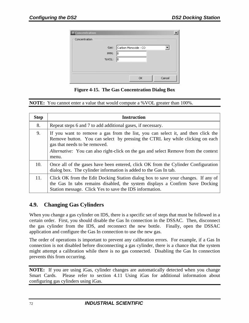
Configuring the DS2 DS2 Docking Station
94 INDUSTRIAL SCIENTIFIC
Figure 4-15. The Gas Concentration Dialog Box
NOTE: You cannot enter a value that would compute a %VOL greater than 100%.
Step Instruction
8. Repeat steps 6 and 7 to add additional gases, if necessary.
9. If you want to remove a gas from the list, you can select it, and then click the Remove button. You can select by pressing the CTRL key while clicking on each gas that needs to be removed. Alternative: You can also right-click on the gas and select Remove from the context menu.
10. Once all of the gases have been entered, click OK from the Cylinder Configuration dialog box. The cylinder information is added to the Gas In tab.
11. Click OK from the Edit Docking Station dialog box to save your changes. If any of the Gas In tabs remains disabled, the system displays a Confirm Save Docking Station message. Click Yes to save the IDS information.
4.9. Changing Gas Cylinders
When you change a gas cylinder on IDS, there is a specific set of steps that must be followed in a certain order. First, you should disable the Gas In connection in the DSSAC. Then, disconnect the gas cylinder from the IDS, and reconnect the new bottle. Finally, open the DSSAC application and configure the Gas In connection to use the new gas.
The order of operations is important to prevent any calibration errors. For example, if a Gas In connection is not disabled before disconnecting a gas cylinder, there is a chance that the system might attempt a calibration while there is no gas connected. Disabling the Gas In connection prevents this from occurring.
NOTE: If you are using iGas, cylinder changes are automatically detected when you change Smart Cards. Please refer to section 4.11 Using iGas for additional information about configuring gas cylinders using iGas.
DS2 Docking Station Configuring the DS2
INDUSTRIAL SCIENTIFIC 95
To change gas cylinders on an IDS, follow the instructions listed below.
Step Instruction
1. Open the DSSAC application. Click the Docking Stations option in the navigation pane.
2. Double-click on the IDS for which you are changing gas cylinders. Alternative: You can also right-click on the IDS and select Properties from the context menu. Alternative: You can also select the IDS, and then click the File menu, and select Properties.
3. Click on the Gas Inlets tab.
4. Click on the Gas In tab that corresponds to the Gas In connection for which you are changing gas cylinders.
5. Click the Assign button, and select Disabled from the menu. This disables the Gas In connection.
6. Click OK from the Edit Docking Station dialog box. Click Yes when the Confirm Docking Station Save message appears.
7. Disconnect the old gas bottle from the IDS. Remove the gas tubing from the fitting on the demand flow regulator. With the gauge facing away from you, unscrew the gas cylinder bottle until it detaches from the regulator.
8. Connect the new gas bottle to the IDS. See section 4.6 Configuring Gas Cylinders for detailed instructions on connecting gas cylinders.
9. Return to the DSSAC application. Click the Docking Stations option in the navigation pane.
10. Double-click on the IDS for which you are changing gas cylinders.
11. Click on the Gas Inlets tab.
12. Click on the Gas In tab that corresponds to the Gas In connection for which you are changing gas cylinders.
13. Click the Assign button, and select ISC or non-ISC from the menu, depending on the gas cylinder you are adding. See the previous sections on using ISC gas or using non-ISC gas for specific procedures for adding ISC or non-ISC cylinders.
14. Click OK from the Edit Docking Station dialog box.
15. The Gas In connection is now configured to use the new gas cylinder.
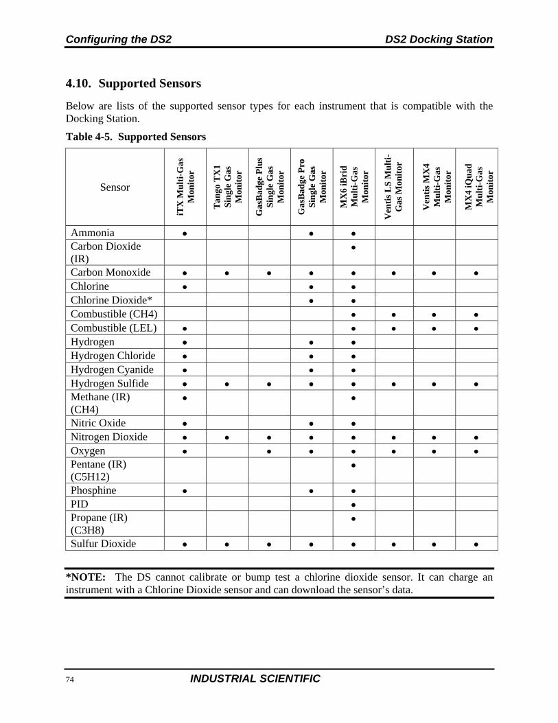
Configuring the DS2 DS2 Docking Station
96 INDUSTRIAL SCIENTIFIC
4.10. Supported Sensors
Below are lists of the supported sensor types for each instrument that is compatible with the Docking Station.
Table 4-5. Supported Sensors
Sensor iT
X M
ult
i-G
as
Mon
itor
Tan
go T
X1
Sin
gle
Gas
M
onit
or
Gas
Bad
ge P
lus
Sin
gle
Gas
M
onit
or
Gas
Bad
ge P
ro
Sin
gle
Gas
M
onit
or
MX
6 iB
rid
M
ult
i-G
as
Mon
itor
Ven
tis
LS
Mu
lti-
Gas
Mon
itor
Ven
tis
MX
4 M
ult
i-G
as
Mon
itor
MX
4 iQ
uad
M
ult
i-G
as
Mon
itor
Ammonia Carbon Dioxide (IR)
Carbon Monoxide Chlorine Chlorine Dioxide* Combustible (CH4) Combustible (LEL) Hydrogen Hydrogen Chloride Hydrogen Cyanide Hydrogen Sulfide Methane (IR) (CH4)
Nitric Oxide Nitrogen Dioxide Oxygen Pentane (IR) (C5H12)
Phosphine PID Propane (IR) (C3H8)
Sulfur Dioxide
*NOTE: The DS cannot calibrate or bump test a chlorine dioxide sensor. It can charge an instrument with a Chlorine Dioxide sensor and can download the sensor’s data.
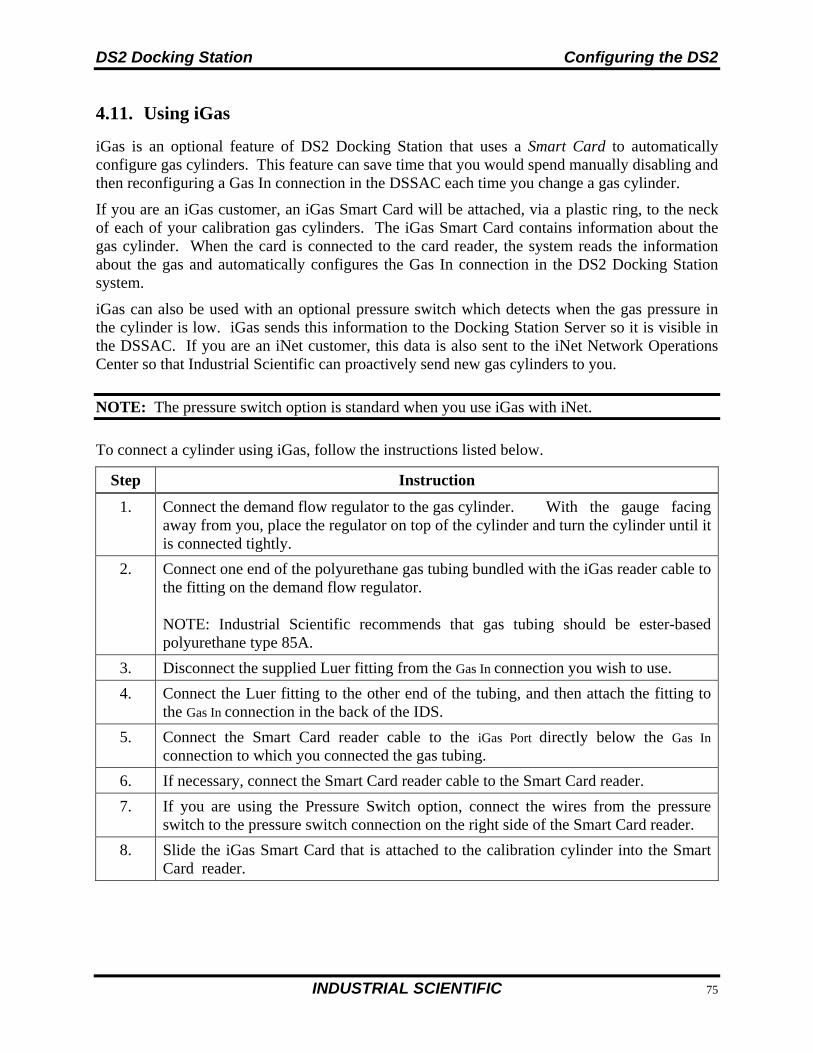
DS2 Docking Station Configuring the DS2
INDUSTRIAL SCIENTIFIC 97
4.11. Using iGas
iGas is an optional feature of DS2 Docking Station that uses a Smart Card to automatically configure gas cylinders. This feature can save time that you would spend manually disabling and then reconfiguring a Gas In connection in the DSSAC each time you change a gas cylinder.
If you are an iGas customer, an iGas Smart Card will be attached, via a plastic ring, to the neck of each of your calibration gas cylinders. The iGas Smart Card contains information about the gas cylinder. When the card is connected to the card reader, the system reads the information about the gas and automatically configures the Gas In connection in the DS2 Docking Station system.
iGas can also be used with an optional pressure switch which detects when the gas pressure in the cylinder is low. iGas sends this information to the Docking Station Server so it is visible in the DSSAC. If you are an iNet customer, this data is also sent to the iNet Network Operations Center so that Industrial Scientific can proactively send new gas cylinders to you.
NOTE: The pressure switch option is standard when you use iGas with iNet.
To connect a cylinder using iGas, follow the instructions listed below.
Step Instruction
1. Connect the demand flow regulator to the gas cylinder. With the gauge facing away from you, place the regulator on top of the cylinder and turn the cylinder until it is connected tightly.
2. Connect one end of the polyurethane gas tubing bundled with the iGas reader cable to the fitting on the demand flow regulator.
NOTE: Industrial Scientific recommends that gas tubing should be ester-based polyurethane type 85A.
3. Disconnect the supplied Luer fitting from the Gas In connection you wish to use.
4. Connect the Luer fitting to the other end of the tubing, and then attach the fitting to the Gas In connection in the back of the IDS.
5. Connect the Smart Card reader cable to the iGas Port directly below the Gas In connection to which you connected the gas tubing.
6. If necessary, connect the Smart Card reader cable to the Smart Card reader.
7. If you are using the Pressure Switch option, connect the wires from the pressure switch to the pressure switch connection on the right side of the Smart Card reader.
8. Slide the iGas Smart Card that is attached to the calibration cylinder into the Smart Card reader.
Configuring the DS2 DS2 Docking Station
98 INDUSTRIAL SCIENTIFIC
Figure 4-16. Diagram of iGas Smart Card and Reader
NOTE: It is important that the gas line is connected before the iGas card so that the system is ready to draw gas after it reads the card.
NOTE: Be sure that the Smart Card is connected to the correct iGas Port. For example, if you have connected the gas line to Gas In # 2, then the Smart Card must be connected to iGas Port #2. If the correct port is not used, the system could use the wrong type of gas for a calibration or bump test, rendering the results inaccurate.
Step Instruction
9. The system reads the information about the gas cylinder from the iGas Smart Card and automatically configures the Gas In connection in the DSSAC.
10. The gas cylinder is ready to use.
NOTE: If you are using iGas, do not edit the cylinder configuration in DSSAC. Doing so could temporarily override the settings configured by iGas, possibly causing DS2 Docking Station to use inaccurate information for calibrations or bump tests. If the
settings do get overwritten, simply reinsert the iGas Smart Card to reconfigure the gas cylinder.
DS2 Docking Station Configuring the DS2
INDUSTRIAL SCIENTIFIC 99
Figure 4-17. Diagram of the Back Plate of an IDS
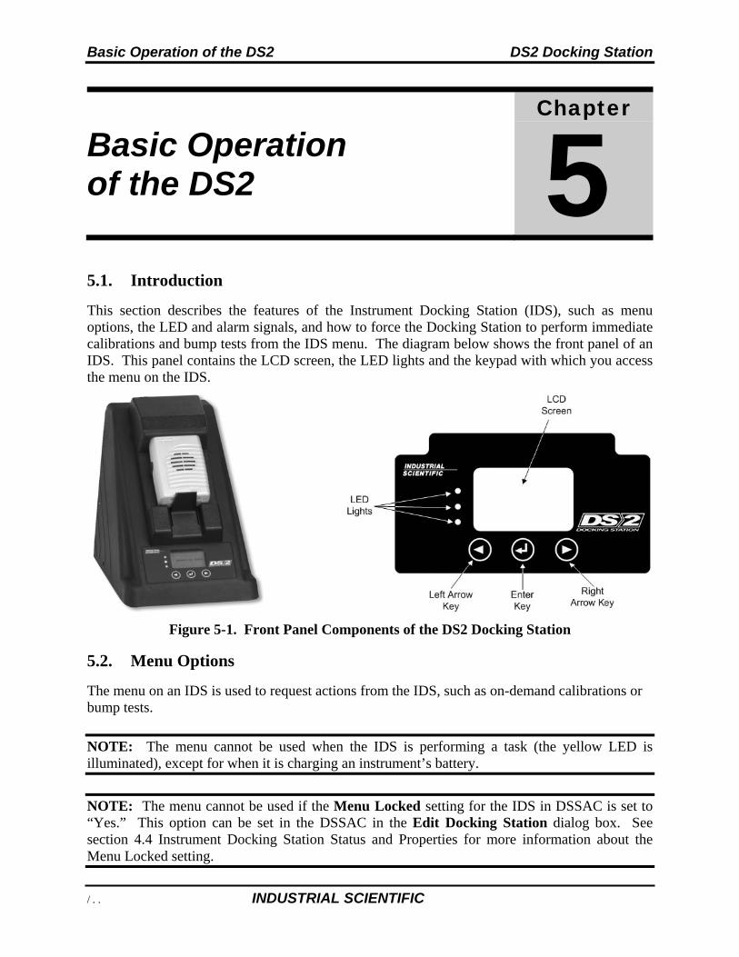
Basic Operation of the DS2 DS2 Docking Station
100 INDUSTRIAL SCIENTIFIC
Basic Operation of the DS2
Chapter
5
5.1. Introduction
This section describes the features of the Instrument Docking Station (IDS), such as menu options, the LED and alarm signals, and how to force the Docking Station to perform immediate calibrations and bump tests from the IDS menu. The diagram below shows the front panel of an IDS. This panel contains the LCD screen, the LED lights and the keypad with which you access the menu on the IDS.
Figure 5-1. Front Panel Components of the DS2 Docking Station
5.2. Menu Options
The menu on an IDS is used to request actions from the IDS, such as on-demand calibrations or bump tests.
NOTE: The menu cannot be used when the IDS is performing a task (the yellow LED is illuminated), except for when it is charging an instrument’s battery.
NOTE: The menu cannot be used if the Menu Locked setting for the IDS in DSSAC is set to “Yes.” This option can be set in the DSSAC in the Edit Docking Station dialog box. See section 4.4 Instrument Docking Station Status and Properties for more information about the Menu Locked setting.
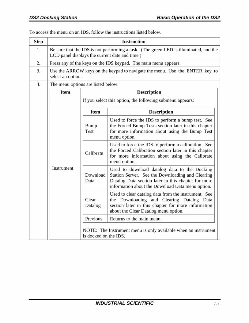
DS2 Docking Station Basic Operation of the DS2
INDUSTRIAL SCIENTIFIC 101
To access the menu on an IDS, follow the instructions listed below.
Step Instruction
1. Be sure that the IDS is not performing a task. (The green LED is illuminated, and the LCD panel displays the current date and time.)
2. Press any of the keys on the IDS keypad. The main menu appears.
3. Use the ARROW keys on the keypad to navigate the menu. Use the ENTER key to select an option.
4. The menu options are listed below.
Item Description
Instrument
If you select this option, the following submenu appears:
Item Description
Bump Test
Used to force the IDS to perform a bump test. See the Forced Bump Tests section later in this chapter for more information about using the Bump Test menu option.
Calibrate
Used to force the IDS to perform a calibration. See the Forced Calibration section later in this chapter for more information about using the Calibrate menu option.
Download Data
Used to download datalog data to the Docking Station Server. See the Downloading and Clearing Datalog Data section later in this chapter for more information about the Download Data menu option.
Clear Datalog
Used to clear datalog data from the instrument. See the Downloading and Clearing Datalog Data section later in this chapter for more information about the Clear Datalog menu option.
Previous Returns to the main menu.
NOTE: The Instrument menu is only available when an instrument is docked on the IDS.
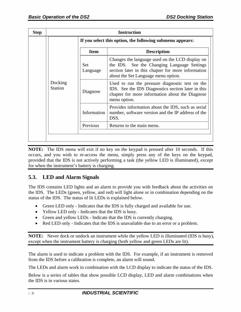
Basic Operation of the DS2 DS2 Docking Station
102 INDUSTRIAL SCIENTIFIC
Step Instruction
Docking Station
If you select this option, the following submenu appears:
Item Description
Set Language
Changes the language used on the LCD display on the IDS. See the Changing Language Settings section later in this chapter for more information about the Set Language menu option.
Diagnose
Used to run the pressure diagnostic test on the IDS. See the IDS Diagnostics section later in this chapter for more information about the Diagnose menu option.
InformationProvides information about the IDS, such as serial number, software version and the IP address of the DSS.
Previous Returns to the main menu.
NOTE: The IDS menu will exit if no key on the keypad is pressed after 10 seconds. If this occurs, and you wish to re-access the menu, simply press any of the keys on the keypad, provided that the IDS is not actively performing a task (the yellow LED is illuminated), except for when the instrument’s battery is charging.
5.3. LED and Alarm Signals
The IDS contains LED lights and an alarm to provide you with feedback about the activities on the IDS. The LEDs (green, yellow, and red) will light alone or in combination depending on the status of the IDS. The status of lit LEDs is explained below.
Green LED only - Indicates that the IDS is fully charged and available for use. Yellow LED only - Indicates that the IDS is busy. Green and yellow LEDs - Indicate that the IDS is currently charging. Red LED only - Indicates that the IDS is unavailable due to an error or a problem.
NOTE: Never dock or undock an instrument while the yellow LED is illuminated (IDS is busy), except when the instrument battery is charging (both yellow and green LEDs are lit).
The alarm is used to indicate a problem with the IDS. For example, if an instrument is removed from the IDS before a calibration is complete, an alarm will sound.
The LEDs and alarm work in combination with the LCD display to indicate the status of the IDS.
Below is a series of tables that show possible LCD display, LED and alarm combinations when the IDS is in various states.
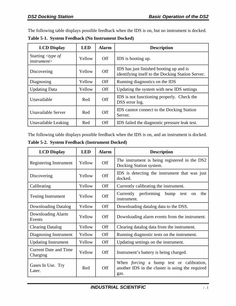
DS2 Docking Station Basic Operation of the DS2
INDUSTRIAL SCIENTIFIC 103
The following table displays possible feedback when the IDS is on, but no instrument is docked.
Table 5-1. System Feedback (No Instrument Docked)
LCD Display LED Alarm Description
Starting <type of instrument>
Yellow Off IDS is booting up.
Discovering Yellow Off IDS has just finished booting up and is identifying itself to the Docking Station Server.
Diagnosing Yellow Off Running diagnostics on the IDS
Updating Data Yellow Off Updating the system with new IDS settings
Unavailable Red Off IDS is not functioning properly. Check the DSS error log.
Unavailable Server Red Off IDS cannot connect to the Docking Station Server.
Unavailable Leaking Red Off IDS failed the diagnostic pressure leak test.
The following table displays possible feedback when the IDS is on, and an instrument is docked.
Table 5-2. System Feedback (Instrument Docked)
LCD Display LED Alarm Description
Registering Instrument Yellow Off The instrument is being registered in the DS2 Docking Station system.
Discovering Yellow Off IDS is detecting the instrument that was just docked.
Calibrating Yellow Off Currently calibrating the instrument.
Testing Instrument Yellow Off Currently performing bump test on the instrument.
Downloading Datalog Yellow Off Downloading datalog data to the DSS.
Downloading Alarm Events
Yellow Off Downloading alarm events from the instrument.
Clearing Datalog Yellow Off Clearing datalog data from the instrument.
Diagnosing Instrument Yellow Off Running diagnostic tests on the instrument.
Updating Instrument Yellow Off Updating settings on the instrument.
Current Date and Time Charging
Yellow Off Instrument’s battery is being charged.
Gases In Use. Try Later.
Red Off When forcing a bump test or calibration, another IDS in the cluster is using the required gas.
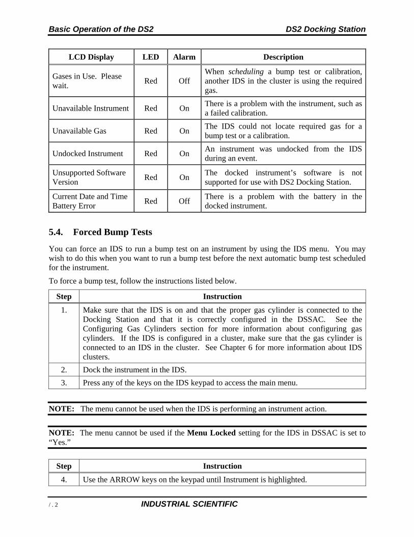
Basic Operation of the DS2 DS2 Docking Station
104 INDUSTRIAL SCIENTIFIC
LCD Display LED Alarm Description
Gases in Use. Please wait.
Red Off When scheduling a bump test or calibration, another IDS in the cluster is using the required gas.
Unavailable Instrument Red On There is a problem with the instrument, such as a failed calibration.
Unavailable Gas Red On The IDS could not locate required gas for a bump test or a calibration.
Undocked Instrument Red On An instrument was undocked from the IDS during an event.
Unsupported Software Version
Red On The docked instrument’s software is not supported for use with DS2 Docking Station.
Current Date and Time Battery Error
Red Off There is a problem with the battery in the docked instrument.
5.4. Forced Bump Tests
You can force an IDS to run a bump test on an instrument by using the IDS menu. You may wish to do this when you want to run a bump test before the next automatic bump test scheduled for the instrument.
To force a bump test, follow the instructions listed below.
Step Instruction
1. Make sure that the IDS is on and that the proper gas cylinder is connected to the Docking Station and that it is correctly configured in the DSSAC. See the Configuring Gas Cylinders section for more information about configuring gas cylinders. If the IDS is configured in a cluster, make sure that the gas cylinder is connected to an IDS in the cluster. See Chapter 6 for more information about IDS clusters.
2. Dock the instrument in the IDS.
3. Press any of the keys on the IDS keypad to access the main menu.
NOTE: The menu cannot be used when the IDS is performing an instrument action.
NOTE: The menu cannot be used if the Menu Locked setting for the IDS in DSSAC is set to “Yes.”
Step Instruction
4. Use the ARROW keys on the keypad until Instrument is highlighted.
DS2 Docking Station Basic Operation of the DS2
INDUSTRIAL SCIENTIFIC 105
Step Instruction
5. Press the ENTER key. The Instrument menu appears.
6. Use the ARROW keys on the keypad to select Bump Test. Press the ENTER key.
7. The LCD displays a confirmation prompt: “Are you sure?” Use the ARROW keys on the keypad to highlight Yes and then press the ENTER key. If you select No, the LCD returns to the main menu.
8. The IDS begins performing the bump test. The LCD displays “Testing Instrument.” The yellow LED is illuminated.
9. When the bump test is complete, the LCD returns to the main menu, and the green LED is illuminated.
NOTE: In the event of a failed sensor (Cl2, HCl, or NH3), the docking station ignores any large reading that are above the sensor’s maximum reading. In addition, the docking station ignores any negative readings whose absolute value is larger than the sensor’s maximum reading.
NOTE: If the instrument fails the bump test, the IDS will perform a calibration. If the calibration fails, then the red LED illuminates and the IDS sounds an alarm. If the oxygen sensor fails the bump test, the DS2 will display an “Unavailable Instrument” message.
5.5. Calibration
5.5.1. Forced Calibrations
You can force an IDS to calibrate an instrument by using the IDS menu. You may wish to do this when you want to perform a calibration prior to the next calibration scheduled for the instrument.
To force a calibration, follow the instructions listed below.
Step Instruction
1. Make sure that the IDS is on and that the proper gas cylinder is connected to the IDS and that it is correctly configured in the DSSAC. See section 4.6 Configuring Gas Cylinders for more information about configuring gas cylinders. If the IDS is configured in a cluster, make sure that the gas cylinder is connected to a IDS in the cluster. See Chapter 6 for more information about IDS clusters.
2. Dock the instrument in the IDS.
3. Press any of the keys on the IDS keypad to access the main menu.
NOTE: The menu cannot be used when the IDS is performing an instrument action.
NOTE: The menu cannot be used if the Menu Locked setting for the IDS in DSSAC is set to “Yes.”
Basic Operation of the DS2 DS2 Docking Station
106 INDUSTRIAL SCIENTIFIC
Step Instruction
4. Use the ARROW keys on the keypad until Instrument is highlighted.
5. Press the ENTER key. The Instrument menu appears.
6. Use the ARROW keys on the keypad to highlight Calibrate. Press the ENTER key.
7. The LCD displays a confirmation prompt: “Are you sure?” Use the ARROW keys on the keypad to highlight Yes, and then press the ENTER key. If you select No, the LCD returns to the main menu.
8. The IDS begins performing the calibration. The LCD displays “Calibrating.” The yellow LED is illuminated.
9. When the calibration is complete, the LCD returns to the main menu and the green LED is illuminated.
NOTE: If the instrument fails the calibration, the red LED illuminates and the Docking Station sounds an alarm.
5.5.2. O2 Sensor Failures During Calibrations
If an O2 sensor fails a DS2 bump test in any docked instrument, the IDS will display the red light, and the message “Unavailable instrument”, and will beep. Underneath the “Unavailable Instrument” message, the IDS will display “O2 Bump Failure” in parenthesis.
Figure 5-2. DS2 Error Screen after O2 Sensor Failure
An automatic calibration will not take place if an O2 sensor fails a bump test, regardless of what other sensors are installed. In addition, most forced events will also not be allowed. This prevents the user from simply forcing a calibration, clearing the error, and thinking all is well.
A forced Bump test will be the only type of forced event which is allowed in this case. All other forced events will simply result in the same “unavailable instrument” message.
NOTE: The only way to clear this error is to either replace the sensor, or to force a bump test and have it pass.
DS2 Docking Station Basic Operation of the DS2
INDUSTRIAL SCIENTIFIC 107
5.6. Download and Clearing Datalog Data
You can force an IDS to download datalog data from an instrument to the Docking Station Server. When you download datalog data from an instrument, the instrument’s datalog memory is also cleared.
You can also choose to clear datalog data on an instrument without downloading it to the system.
5.6.1. Forced Datalog Download
To download datalog data, follow the instructions listed below.
Step Instruction
1. Make sure that the IDS is on.
2. Dock the instrument in the IDS.
3. Press any of the keys on the IDS keypad to access the main menu.
NOTE: The menu cannot be used when the IDS is performing an instrument action.
NOTE: The menu cannot be used if the Menu Locked setting for the IDS in DSSAC is set to “Yes.”
NOTE: If two sensors are installed in the Tango TX1 when the data are logged, DS2 will download data for three sensors. Data from the installed sensors are logged and downloaded as sensor 1 and sensor 2 data. Data that are logged and downloaded as sensor 3 (or VIRTUAL) are algorithm-calculated values that are based on sensor 1 and sensor 2 data. DSSAC displays only the VIRTUAL data.
If only one sensor is installed or working when the data are logged, the downloaded and DSSAC-displayed data will contain only information for that sensor.
Step Instruction
4. Use the ARROW keys on the keypad until Instrument is highlighted.
5. Press the ENTER key. The Instrument menu appears.
6. Use the ARROW keys on the keypad to select Download Datalog. Press the ENTER key.
7. The LCD displays a confirmation prompt: “Are you sure?” Use the ARROW keys on the keypad to highlight Yes, and then press the ENTER key. If you select No, the LCD returns to the main menu.
8. The IDS begins downloading the datalog data. The LCD displays “Downloading Datalog.” The yellow LED is illuminated. NOTE: The instrument’s datalog memory is also cleared. The LCD displays “Clearing Datalog” when the datalog data is being cleared.
Basic Operation of the DS2 DS2 Docking Station
108 INDUSTRIAL SCIENTIFIC
Step Instruction
9. When the datalog download is complete, the LCD returns to the main menu and the green LED is illuminated.
5.6.2. Clearing Datalog Data
To clear datalog data from an instrument’s memory without downloading it to the system, follow the instructions listed below.
Step Instruction
1. Make sure that the IDS is on.
2. Dock the instrument in the IDS.
3. Press any of the keys on the IDS keypad to access the main menu.
NOTE: The menu cannot be used when the IDS is performing an instrument action.
NOTE: The menu cannot be used if the Menu Locked setting for the IDS in DSSAC is set to “Yes.”
Step Instruction
4. Use the ARROW keys on the keypad until Instrument is highlighted.
5. Press the ENTER key. The Instrument menu appears.
6. Use the ARROW keys on the keypad to select Clear Datalog. Press the ENTER key.
7. The LCD displays a confirmation prompt: “Are you sure?” Use the ARROW keys on the keypad to highlight Yes, and then press the ENTER key. If you select No, the LCD returns to the main menu.
8. The IDS clears the datalog data from the instrument’s memory. The LCD displays “Clearing Datalog.” The yellow LED is illuminated.
9. When the datalog data has been cleared, the LCD returns to the main menu, and the green LED is illuminated.
5.7. IDS Diagnostics
You can manually run a pressure diagnostics test for an IDS using the menu on the IDS LCD display. This feature can be used to reset the IDS to an available state after a leak has been fixed.
For example, if the cluster fittings are left on the back of the IDS without physically connecting it to be a part of a cluster, the system-automated pressure diagnostics test will detect a leak. After the test fails, the LCD on the IDS will display “Unavailable Leaking.” Once the problem has been corrected (i.e., the cluster fittings are removed), you can manually run the pressure diagnostics test to remove the error state, and allow the IDS to be used.
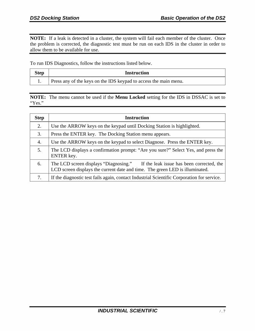
DS2 Docking Station Basic Operation of the DS2
INDUSTRIAL SCIENTIFIC 109
NOTE: If a leak is detected in a cluster, the system will fail each member of the cluster. Once the problem is corrected, the diagnostic test must be run on each IDS in the cluster in order to allow them to be available for use.
To run IDS Diagnostics, follow the instructions listed below.
Step Instruction
1. Press any of the keys on the IDS keypad to access the main menu.
NOTE: The menu cannot be used if the Menu Locked setting for the IDS in DSSAC is set to “Yes.”
Step Instruction
2. Use the ARROW keys on the keypad until Docking Station is highlighted.
3. Press the ENTER key. The Docking Station menu appears.
4. Use the ARROW keys on the keypad to select Diagnose. Press the ENTER key.
5. The LCD displays a confirmation prompt: “Are you sure?” Select Yes, and press the ENTER key.
6. The LCD screen displays “Diagnosing.” If the leak issue has been corrected, the LCD screen displays the current date and time. The green LED is illuminated.
7. If the diagnostic test fails again, contact Industrial Scientific Corporation for service.
Basic Operation of the DS2 DS2 Docking Station
110 INDUSTRIAL SCIENTIFIC
5.8. Instrument Docking Station Operating Guidelines
Use the following safety guidelines to help to ensure your own personal safety and to help protect your Instrument Docking Station and working environment from potential damage.
CAUTION: Compressed gas cylinders and their contents may present specific hazards to the user. Use only in a well-ventilated area. Use only in accordance with the instructions and warnings as marked on the cylinder and the appropriate Material Safety Data Sheet.
5.8.1. General
An Instrument Docking Station (IDS) is a sensitive piece of equipment that should be treated with care. It should be handled in the same way you would handle a laptop computer. General guidelines are listed below.
Install or locate this device only in accordance with the provided installation instructions found in Administrator’s Guide to DS2 Docking Station.
To reduce the risk of fire or electric shock, do not expose the IDS to rain or moisture. Do not operate an IDS with any cover(s) removed. Avoid extremes in temperature. Typical operating temperature should be between -5º C
(23º F) and 40º C (122º F). Do not drop the unit. The IDS should be serviced only by qualified service personnel. Contact Industrial
Scientific Corporation for examination, repair, or adjustment. The power inlet fuse is field replaceable and should be replaced only with a type T6.3A,
250 Volt, fast acting fuse. To help prevent electric shock, plug the IDS power cable into properly grounded
electrical outlets. These cables are equipped with 3-prong plugs to help to ensure proper grounding. Do not use adapter plugs or remove the grounding prong from a cable. If you must use an extension cable, use a 3-wire cable with properly grounded plugs.
Do not use corrosive chemicals or vapors near the IDS. Do not immerse the cord or plug in water. To avoid the potential hazard of electric shock, do not use a IDS during an electrical
storm without proper protection. To avoid the potential hazard of electric shock, do not connect or disconnect any cables
to or from the IDS during an electrical storm. To avoid possible damage to the system board, wait 5 seconds after turning off the IDS
before restarting. To avoid shorting out an IDS when disconnecting a network cable, first unplug the cable
from the network adapter on the back of the IDS, and then from the network jack. When reconnecting a network cable to a IDS, first plug the cable into the network jack, and then into the network adapter on the back of the IDS.
To help protect an IDS from sudden, transient increases and decreases in electrical power, use a surge suppressor, line conditioner, or uninterruptible power supply (UPS).
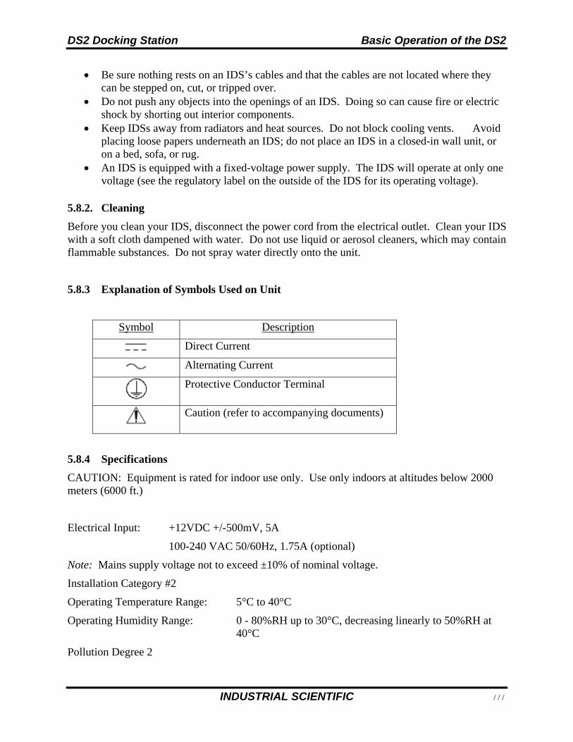
DS2 Docking Station Basic Operation of the DS2
INDUSTRIAL SCIENTIFIC 111
Be sure nothing rests on an IDS’s cables and that the cables are not located where they can be stepped on, cut, or tripped over.
Do not push any objects into the openings of an IDS. Doing so can cause fire or electric shock by shorting out interior components.
Keep IDSs away from radiators and heat sources. Do not block cooling vents. Avoid placing loose papers underneath an IDS; do not place an IDS in a closed-in wall unit, or on a bed, sofa, or rug.
An IDS is equipped with a fixed-voltage power supply. The IDS will operate at only one voltage (see the regulatory label on the outside of the IDS for its operating voltage).
5.8.2. Cleaning
Before you clean your IDS, disconnect the power cord from the electrical outlet. Clean your IDS with a soft cloth dampened with water. Do not use liquid or aerosol cleaners, which may contain flammable substances. Do not spray water directly onto the unit.
5.8.3 Explanation of Symbols Used on Unit
Symbol Description
Direct Current
Alternating Current
Protective Conductor Terminal
Caution (refer to accompanying documents)
5.8.4 Specifications
CAUTION: Equipment is rated for indoor use only. Use only indoors at altitudes below 2000 meters (6000 ft.)
Electrical Input: +12VDC +/-500mV, 5A
100-240 VAC 50/60Hz, 1.75A (optional)
Note: Mains supply voltage not to exceed ±10% of nominal voltage.
Installation Category #2
Operating Temperature Range: 5°C to 40°C
Operating Humidity Range: 0 - 80%RH up to 30°C, decreasing linearly to 50%RH at 40°C
Pollution Degree 2
Basic Operation of the DS2 DS2 Docking Station
112 INDUSTRIAL SCIENTIFIC
5.8.5. Regulatory Notices
Electromagnetic Interference (EMI) is any signal or emission, radiated in free space or conducted along power or signal leads, that endangers the functioning of radio navigation or other safety service or seriously degrades, obstructs, or repeatedly interrupts a licensed radio communications service. Radio communications services include but are not limited to AM/FM commercial broadcast, television, cellular services, radar, air-traffic control, pager, and Personal Communication Services (PCS). These licensed services, along with unintentional radiators such as digital devices, including computer systems, contribute to the electromagnetic environment.
5.8.6. Wiring Requirements
Voltage used must be the same as specified on this device (120/240 VAC) or 12VDC. Using a higher voltage is dangerous and may result in a fire or other accident causing device damage. Using a lower voltage will cause unexpected results. Industrial Scientific is NOT responsible for damage resulting from improper use of an IDS.
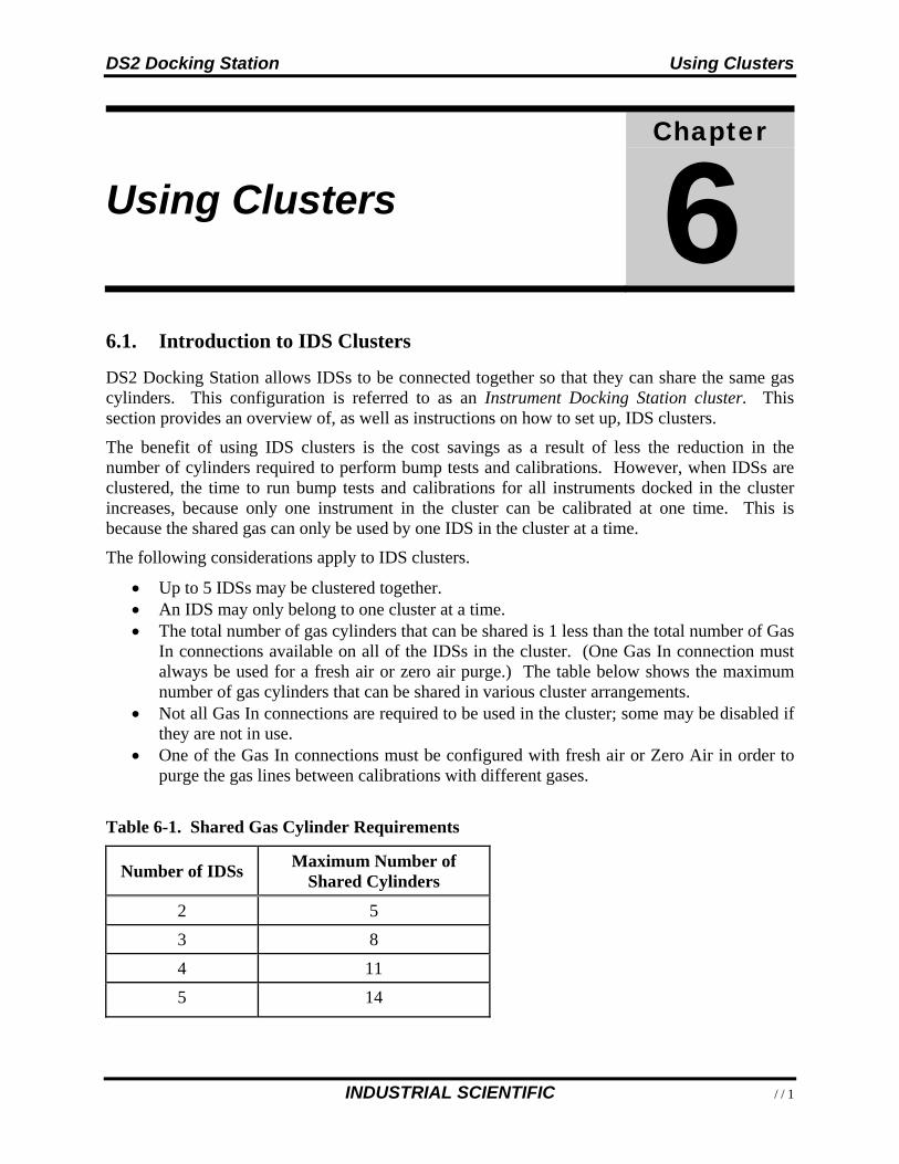
DS2 Docking Station Using Clusters
INDUSTRIAL SCIENTIFIC 113
Using Clusters
Chapter
6
6.1. Introduction to IDS Clusters
DS2 Docking Station allows IDSs to be connected together so that they can share the same gas cylinders. This configuration is referred to as an Instrument Docking Station cluster. This section provides an overview of, as well as instructions on how to set up, IDS clusters.
The benefit of using IDS clusters is the cost savings as a result of less the reduction in the number of cylinders required to perform bump tests and calibrations. However, when IDSs are clustered, the time to run bump tests and calibrations for all instruments docked in the cluster increases, because only one instrument in the cluster can be calibrated at one time. This is because the shared gas can only be used by one IDS in the cluster at a time.
The following considerations apply to IDS clusters.
Up to 5 IDSs may be clustered together. An IDS may only belong to one cluster at a time. The total number of gas cylinders that can be shared is 1 less than the total number of Gas
In connections available on all of the IDSs in the cluster. (One Gas In connection must always be used for a fresh air or zero air purge.) The table below shows the maximum number of gas cylinders that can be shared in various cluster arrangements.
Not all Gas In connections are required to be used in the cluster; some may be disabled if they are not in use.
One of the Gas In connections must be configured with fresh air or Zero Air in order to purge the gas lines between calibrations with different gases.
Table 6-1. Shared Gas Cylinder Requirements
Number of IDSs Maximum Number of
Shared Cylinders
2 5
3 8
4 11
5 14
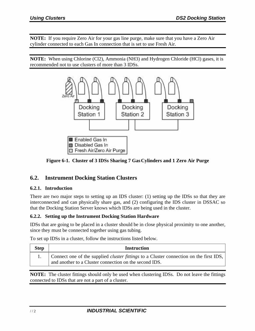
Using Clusters DS2 Docking Station
114 INDUSTRIAL SCIENTIFIC
NOTE: If you require Zero Air for your gas line purge, make sure that you have a Zero Air cylinder connected to each Gas In connection that is set to use Fresh Air.
NOTE: When using Chlorine (Cl2), Ammonia (NH3) and Hydrogen Chloride (HCl) gases, it is recommended not to use clusters of more than 3 IDSs.
Figure 6-1. Cluster of 3 IDSs Sharing 7 Gas Cylinders and 1 Zero Air Purge
6.2. Instrument Docking Station Clusters
6.2.1. Introduction
There are two major steps to setting up an IDS cluster: (1) setting up the IDSs so that they are interconnected and can physically share gas, and (2) configuring the IDS cluster in DSSAC so that the Docking Station Server knows which IDSs are being used in the cluster.
6.2.2. Setting up the Instrument Docking Station Hardware
IDSs that are going to be placed in a cluster should be in close physical proximity to one another, since they must be connected together using gas tubing.
To set up IDSs in a cluster, follow the instructions listed below.
Step Instruction
1. Connect one of the supplied cluster fittings to a Cluster connection on the first IDS, and another to a Cluster connection on the second IDS.
NOTE: The cluster fittings should only be used when clustering IDSs. Do not leave the fittings connected to IDSs that are not a part of a cluster.
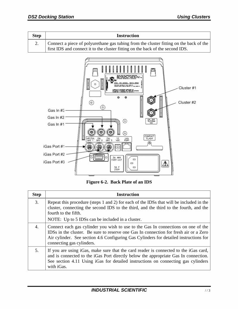
DS2 Docking Station Using Clusters
INDUSTRIAL SCIENTIFIC 115
Step Instruction
2. Connect a piece of polyurethane gas tubing from the cluster fitting on the back of the first IDS and connect it to the cluster fitting on the back of the second IDS.
Figure 6-2. Back Plate of an IDS
Step Instruction
3. Repeat this procedure (steps 1 and 2) for each of the IDSs that will be included in the cluster, connecting the second IDS to the third, and the third to the fourth, and the fourth to the fifth. NOTE: Up to 5 IDSs can be included in a cluster.
4. Connect each gas cylinder you wish to use to the Gas In connections on one of the IDSs in the cluster. Be sure to reserve one Gas In connection for fresh air or a Zero Air cylinder. See section 4.6 Configuring Gas Cylinders for detailed instructions for connecting gas cylinders.
5. If you are using iGas, make sure that the card reader is connected to the iGas card, and is connected to the iGas Port directly below the appropriate Gas In connection. See section 4.11 Using iGas for detailed instructions on connecting gas cylinders with iGas.
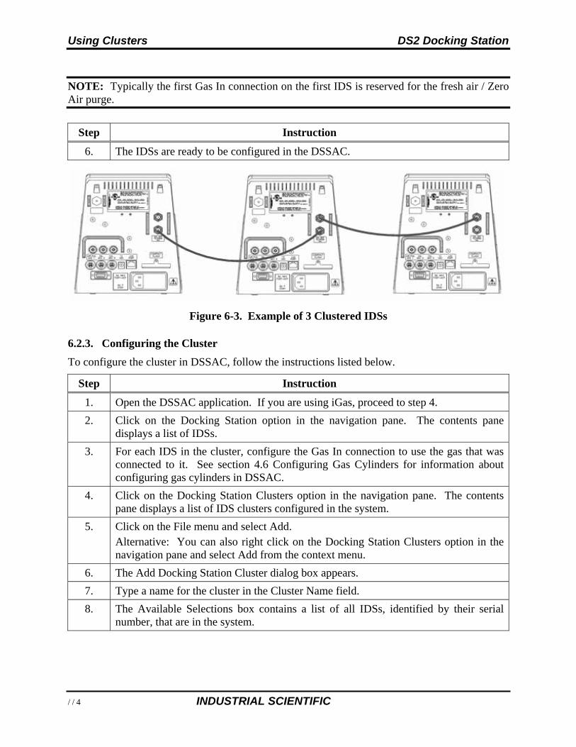
Using Clusters DS2 Docking Station
116 INDUSTRIAL SCIENTIFIC
NOTE: Typically the first Gas In connection on the first IDS is reserved for the fresh air / Zero Air purge.
Step Instruction
6. The IDSs are ready to be configured in the DSSAC.
Figure 6-3. Example of 3 Clustered IDSs
6.2.3. Configuring the Cluster
To configure the cluster in DSSAC, follow the instructions listed below.
Step Instruction
1. Open the DSSAC application. If you are using iGas, proceed to step 4.
2. Click on the Docking Station option in the navigation pane. The contents pane displays a list of IDSs.
3. For each IDS in the cluster, configure the Gas In connection to use the gas that was connected to it. See section 4.6 Configuring Gas Cylinders for information about configuring gas cylinders in DSSAC.
4. Click on the Docking Station Clusters option in the navigation pane. The contents pane displays a list of IDS clusters configured in the system.
5. Click on the File menu and select Add. Alternative: You can also right click on the Docking Station Clusters option in the navigation pane and select Add from the context menu.
6. The Add Docking Station Cluster dialog box appears.
7. Type a name for the cluster in the Cluster Name field.
8. The Available Selections box contains a list of all IDSs, identified by their serial number, that are in the system.
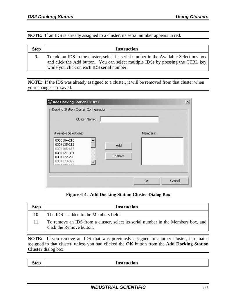
DS2 Docking Station Using Clusters
INDUSTRIAL SCIENTIFIC 117
NOTE: If an IDS is already assigned to a cluster, its serial number appears in red.
Step Instruction
9. To add an IDS to the cluster, select its serial number in the Available Selections box and click the Add button. You can select multiple IDSs by pressing the CTRL key while you click on each IDS serial number.
NOTE: If the IDS was already assigned to a cluster, it will be removed from that cluster when your changes are saved.
Figure 6-4. Add Docking Station Cluster Dialog Box
Step Instruction
10. The IDS is added to the Members field.
11. To remove an IDS from a cluster, select its serial number in the Members box, and click the Remove button.
NOTE: If you remove an IDS that was previously assigned to another cluster, it remains assigned to that cluster, unless you had clicked the OK button from the Add Docking Station Cluster dialog box.
Step Instruction
Using Clusters DS2 Docking Station
118 INDUSTRIAL SCIENTIFIC
Step Instruction
12. The IDS is removed from the Members field and appears in the Available Selections box.
13. Click the OK button to save the IDS cluster. The cluster is ready to be used by the system.
6.2.4. Removing a Cluster
If a cluster is no longer in use, you can remove it from the system. To remove a cluster, follow the instructions listed below.
Step Instruction
1. Open the DSSAC application. If you are using iGas, proceed to step 4.
2. Click on the Docking Station Clusters option in the navigation pane. The contents pane displays a list of IDS clusters configured in the system.
3. Select the IDS cluster you would like to remove.
4. Click on the File menu and select Remove. Alternative: You can also right click on the IDS cluster in the contents pane and select Remove from the context menu. You can select multiple IDS clusters by pressing the CTRL key while you click on each IDS cluster.
5. A confirmation prompt will appear. Click Yes to remove the IDS cluster.
DS2 Docking Station Event Scheduling
INDUSTRIAL SCIENTIFIC 119
Event Scheduling
Chapter
7
7.1. Introduction
An event is an activity that automatically occurs in DS2 Docking Station. You determine when these events run by scheduling them in the DSSAC.
NOTE: Only users assigned to the Systems Administrator role can edit and add events. Users assigned to the Technician role may view events, but not change them.
The types of events that you can schedule at particular dates and/or times in DS2 Docking Station are:
Calibration - Used to automatically calibrate an instrument. Alarm Events Download - Used to automatically downloading alarm events from an
instrument Bump Test - Used to automatically perform bump tests on an instrument. Datalog Download - Used to download datalog data from an instrument. Diagnostics - Used to run diagnostic tests on an instrument or IDS. The results of these
tests are sent to the iNet Network Operations Center for analysis.
NOTE: There are also two events that occur automatically in the system. These events are Settings Update and Settings Read. “Settings Update” controls the transfer of option information from the DS2 Docking Station Server to instruments and IDSs. “Settings Read” handles registration of new Docking Stations, instruments, and components. These events occur daily for IDSs, and upon docking for instruments.
NOTE: If two sensors are installed in the Tango TX1 when the data are logged, DS2 will download data for three sensors. Data from the installed sensors are logged and downloaded as sensor 1 and sensor 2. Data that are logged and downloaded as sensor 3 (or VIRTUAL) are algorithm-calculated values that are based on sensor 1 and sensor 2 data. DSSAC displays only the VIRTUAL data.
If only one sensor is installed or working when the data are logged, the downloaded and DSSAC- displayed data will contain only information for that sensor.
Event Scheduling DS2 Docking Station
120 INDUSTRIAL SCIENTIFIC
There are two types of events.
Global -These events are built into the system, and apply to all IDSs or instruments that are configured in your Docking Station Network. There are Global events for both IDSs and instruments.
Special -These events are created by an administrator, and apply only to the instruments designated to use them. Special events override Global events. For example, if an instrument is configured to use a Special calibration event, it calibrates according to the schedule set in the Special event, and not the Global calibration event. The Global calibration event is ignored for that instrument.
Events can be run at the following intervals.
Upon Docking -The event will run each time that an instrument is placed on the IDS. This interval only applies to instrument events.
Daily -The event runs each day at a specified time, or whenever the IDS or instrument is available that day.
Weekly - The event runs on the specified day of the week at a specified time, or whenever the IDS or instrument is available on the specified day or thereafter.
Monthly -The event runs on the specified day of the month at a specified time, or whenever the IDS or instrument is available on the specified day or thereafter.
Quarterly - The event runs once each 90 days, or whenever the IDS or instrument is available on the specified day or thereafter.
NOTE: If an IDS or instrument is not available at the scheduled time, the event will run for that IDS or instrument the next time it is available. For example, if an instrument event is set up to run weekly on Tuesdays, and an instrument is not docked until Wednesday, the event will run on Wednesday for that instrument.
7.2. Global Events
Global events apply to all IDSs or instruments in your Docking Station Network. You cannot add or remove global events. However, you can schedule global events to run at a time that you specify.
7.2.1. Global Instrument Docking Station Events
There is one global Instrument Docking Station event built-in to the system:
Diagnostics.
By default, the Diagnostics IDS event is set to run Daily at midnight.
NOTE: Starting in version 5.0, the Diagnostics IDS event is set to run Daily at 12:30 AM, not midnight. For upgrades to DSS, default event schedules are not be modified by the installer.
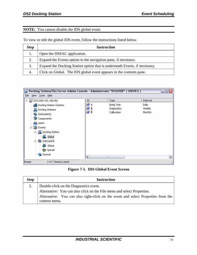
DS2 Docking Station Event Scheduling
INDUSTRIAL SCIENTIFIC 121
NOTE: You cannot disable the IDS global event.
To view or edit the global IDS event, follow the instructions listed below.
Step Instruction
1. Open the DSSAC application.
2. Expand the Events option in the navigation pane, if necessary.
3. Expand the Docking Station option that is underneath Events, if necessary.
4. Click on Global. The IDS global event appears in the contents pane.
Figure 7-1. IDS Global Event Screen
Step Instruction
5. Double-click on the Diagnostics event. Alternative: You can also click on the File menu and select Properties. Alternative: You can also right-click on the event and select Properties from the context menu.
1 2 3
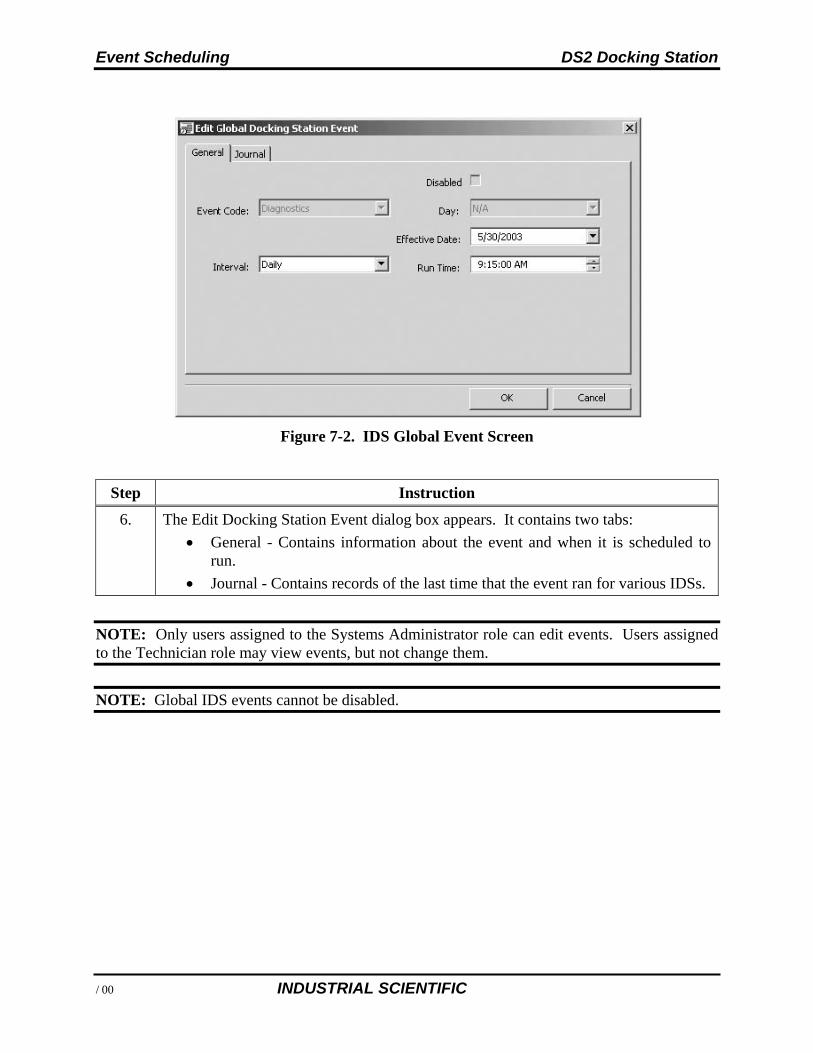
Event Scheduling DS2 Docking Station
122 INDUSTRIAL SCIENTIFIC
Figure 7-2. IDS Global Event Screen
Step Instruction
6. The Edit Docking Station Event dialog box appears. It contains two tabs:
General - Contains information about the event and when it is scheduled to run.
Journal - Contains records of the last time that the event ran for various IDSs.
NOTE: Only users assigned to the Systems Administrator role can edit events. Users assigned to the Technician role may view events, but not change them.
NOTE: Global IDS events cannot be disabled.
DS2 Docking Station Event Scheduling
INDUSTRIAL SCIENTIFIC 123
Step Instruction
7. From the General tab, select an Interval. The choices are:
Daily -If you select “Daily,” you must also specify an Effective Date to indicate when the event should start running.
Weekly -If you select “Weekly,” you must also select a Day (e.g., Sunday, Monday, etc.) to indicate the day of the week on which the event should run, and specify an Effective Date to indicate when the event should start running.
Monthly -If you select “Monthly,” you must also select a Day (e.g., 1st, 2nd, 3rd . 31st) to indicate the day of the month on which the event should run, and specify an Effective Date to indicate when the event should start running.
NOTE: If you select the 30th or 31st as the Day, the event runs on the last day of the month for months that do not have 30 or 31 days, e.g., the event would run on February 28th.
Step Instruction
8. Click OK to save the changes to the Event.
7.2.2. Global Instrument Events
The global instrument events that are built-in to the system are:
Bump Test Bump Test (Tango) Diagnostics Calibration Alarms Download Datalog.
See Table 7-1 for the default settings for each of these events.
NOTE: You can disable instrument global events that you do not want to run.
To view or edit a global Instrument Event, follow the instructions listed below.
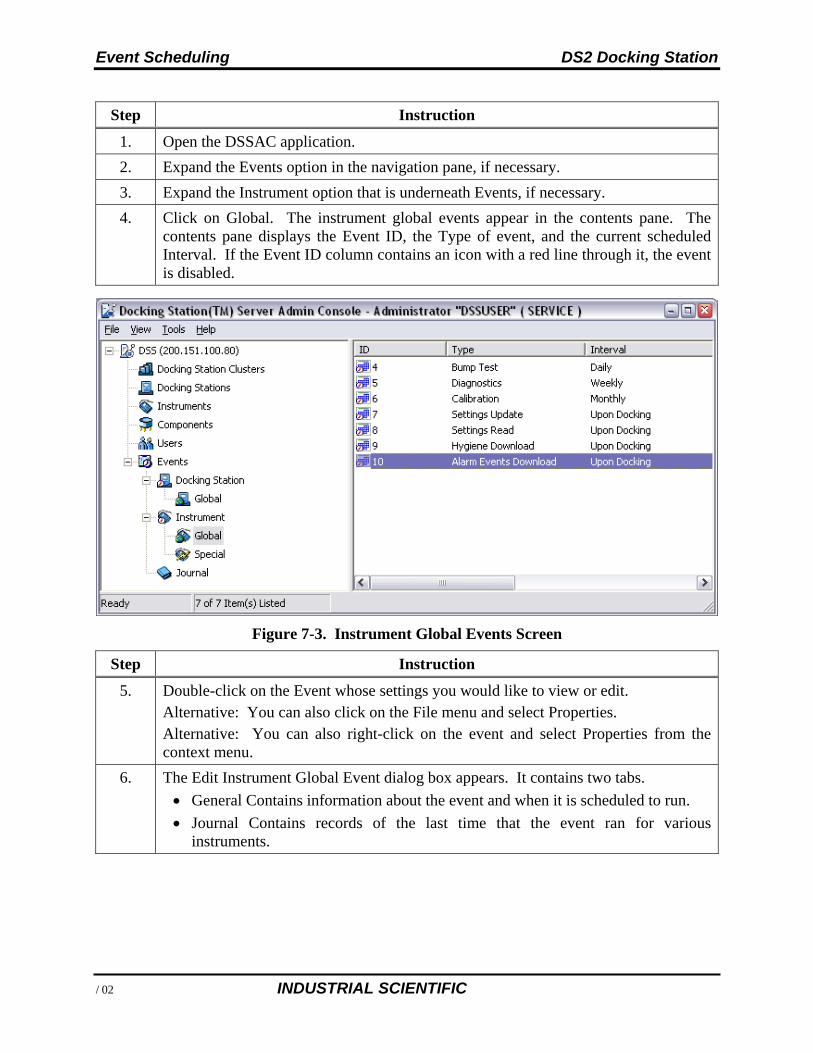
Event Scheduling DS2 Docking Station
124 INDUSTRIAL SCIENTIFIC
Step Instruction
1. Open the DSSAC application.
2. Expand the Events option in the navigation pane, if necessary.
3. Expand the Instrument option that is underneath Events, if necessary.
4. Click on Global. The instrument global events appear in the contents pane. The contents pane displays the Event ID, the Type of event, and the current scheduled Interval. If the Event ID column contains an icon with a red line through it, the event is disabled.
Figure 7-3. Instrument Global Events Screen
Step Instruction
5. Double-click on the Event whose settings you would like to view or edit. Alternative: You can also click on the File menu and select Properties. Alternative: You can also right-click on the event and select Properties from the context menu.
6. The Edit Instrument Global Event dialog box appears. It contains two tabs.
General Contains information about the event and when it is scheduled to run.
Journal Contains records of the last time that the event ran for various instruments.
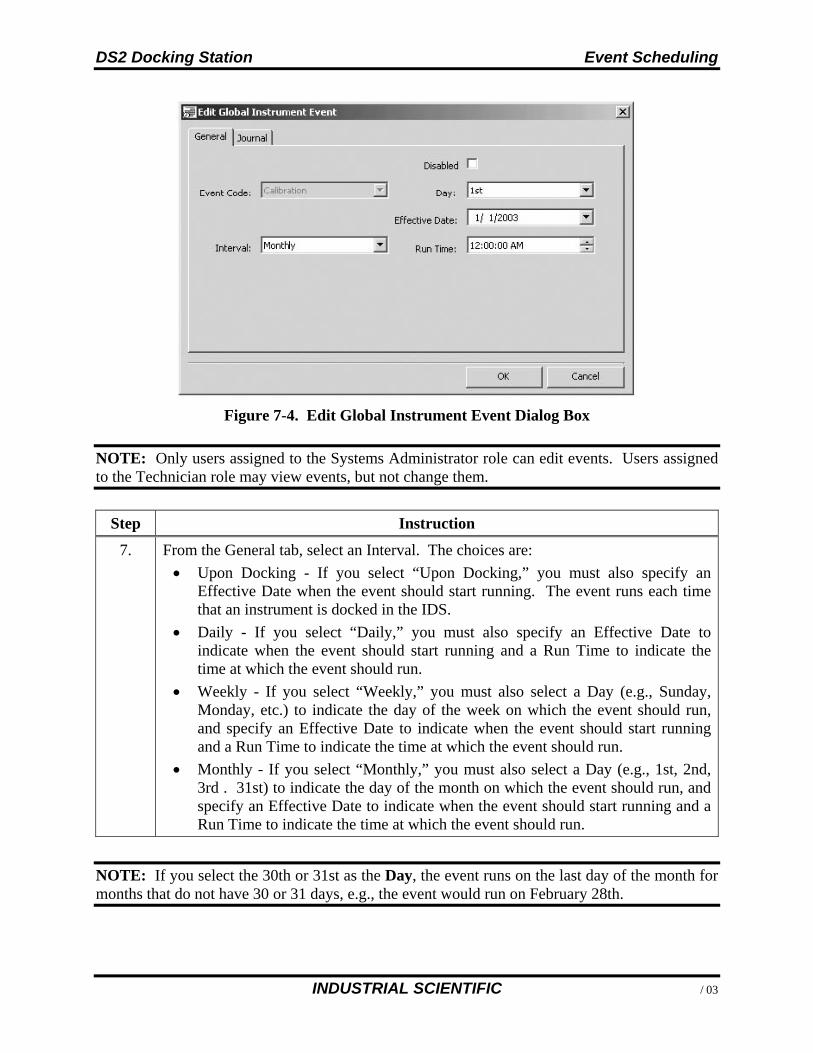
DS2 Docking Station Event Scheduling
INDUSTRIAL SCIENTIFIC 125
Figure 7-4. Edit Global Instrument Event Dialog Box
NOTE: Only users assigned to the Systems Administrator role can edit events. Users assigned to the Technician role may view events, but not change them.
Step Instruction
7. From the General tab, select an Interval. The choices are:
Upon Docking - If you select “Upon Docking,” you must also specify an Effective Date when the event should start running. The event runs each time that an instrument is docked in the IDS.
Daily - If you select “Daily,” you must also specify an Effective Date to indicate when the event should start running and a Run Time to indicate the time at which the event should run.
Weekly - If you select “Weekly,” you must also select a Day (e.g., Sunday, Monday, etc.) to indicate the day of the week on which the event should run, and specify an Effective Date to indicate when the event should start running and a Run Time to indicate the time at which the event should run.
Monthly - If you select “Monthly,” you must also select a Day (e.g., 1st, 2nd, 3rd . 31st) to indicate the day of the month on which the event should run, and specify an Effective Date to indicate when the event should start running and a Run Time to indicate the time at which the event should run.
NOTE: If you select the 30th or 31st as the Day, the event runs on the last day of the month for months that do not have 30 or 31 days, e.g., the event would run on February 28th.
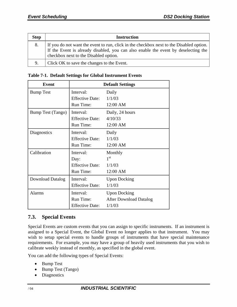
Event Scheduling DS2 Docking Station
126 INDUSTRIAL SCIENTIFIC
Step Instruction
8. If you do not want the event to run, click in the checkbox next to the Disabled option. If the Event is already disabled, you can also enable the event by deselecting the checkbox next to the Disabled option.
9. Click OK to save the changes to the Event.
Table 7-1. Default Settings for Global Instrument Events
Event Default Settings
Bump Test Interval: Daily Effective Date: 1/1/03 Run Time: 12:00 AM
Bump Test (Tango) Interval: Daily, 24 hours Effective Date: 4/10/33 Run Time: 12:00 AM
Diagnostics Interval: Daily Effective Date: 1/1/03 Run Time: 12:00 AM
Calibration Interval: Monthly Day: 1st Effective Date: 1/1/03 Run Time: 12:00 AM
Download Datalog Interval: Upon Docking Effective Date: 1/1/03
Alarms Interval: Upon Docking Run Time: After Download Datalog Effective Date: 1/1/03
7.3. Special Events
Special Events are custom events that you can assign to specific instruments. If an instrument is assigned to a Special Event, the Global Event no longer applies to that instrument. You may wish to setup special events to handle groups of instruments that have special maintenance requirements. For example, you may have a group of heavily used instruments that you wish to calibrate weekly instead of monthly, as specified in the global event.
You can add the following types of Special Events:
Bump Test Bump Test (Tango) Diagnostics
DS2 Docking Station Event Scheduling
INDUSTRIAL SCIENTIFIC 127
Calibration Alarms Download datalog.
NOTE: The “Bump Test (Tango)” special event is system created. It applies to any Tango instrument that is in single-sensor mode or has two installed sensors and one is in calibration fail. When any Tango TX1 instrument is in either state, DSS will override any other bump test event for the unit.
To add a Special Event for an instrument, follow the instructions listed below.
Step Instruction
1. Open the DSSAC application.
2. Expand the Events option in the navigation pane, if necessary.
3. Expand the Instrument option that is underneath Events, if necessary.
4. Click on Special. Any instrument Special Events that have been previously added appear in the contents pane. The contents pane displays the Event ID, the Type of event, the current scheduled Interval, and the Event Name. If the Event ID column contains an icon with a red line through it, the event is disabled.
5. Click the File menu and select Add. Alternative: You can also right click on the Special option in the navigation pane and select Add from the context menu.
NOTE: Only users assigned to the Systems Administrator role can add special events. Users assigned to the Technician role may view events, but not change them.
Step Instruction
6. The Add Instrument Special Event dialog box appears.
7. Select an Event Code. The choices are:
Bump Test
Bump Test (Tango)
Diagnostics
Calibration
Alarms
Download Datalog.
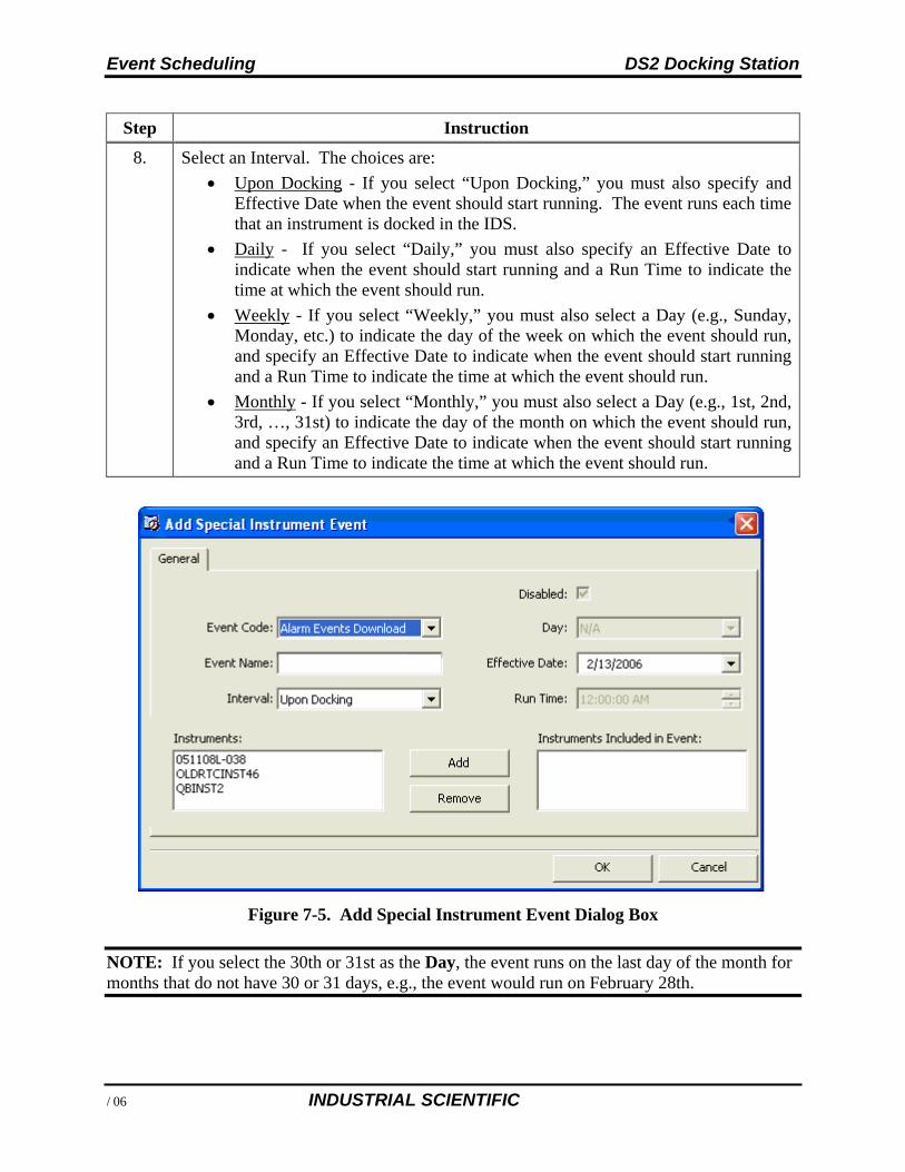
Event Scheduling DS2 Docking Station
128 INDUSTRIAL SCIENTIFIC
Step Instruction
8. Select an Interval. The choices are:
Upon Docking - If you select “Upon Docking,” you must also specify and Effective Date when the event should start running. The event runs each time that an instrument is docked in the IDS.
Daily - If you select “Daily,” you must also specify an Effective Date to indicate when the event should start running and a Run Time to indicate the time at which the event should run.
Weekly - If you select “Weekly,” you must also select a Day (e.g., Sunday, Monday, etc.) to indicate the day of the week on which the event should run, and specify an Effective Date to indicate when the event should start running and a Run Time to indicate the time at which the event should run.
Monthly - If you select “Monthly,” you must also select a Day (e.g., 1st, 2nd, 3rd, …, 31st) to indicate the day of the month on which the event should run, and specify an Effective Date to indicate when the event should start running and a Run Time to indicate the time at which the event should run.
Figure 7-5. Add Special Instrument Event Dialog Box
NOTE: If you select the 30th or 31st as the Day, the event runs on the last day of the month for months that do not have 30 or 31 days, e.g., the event would run on February 28th.
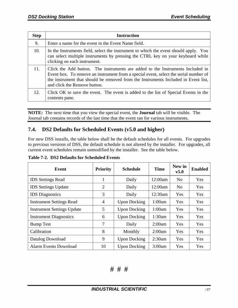
DS2 Docking Station Event Scheduling
INDUSTRIAL SCIENTIFIC 129
Step Instruction
9. Enter a name for the event in the Event Name field.
10. In the Instruments field, select the instrument to which the event should apply. You can select multiple instruments by pressing the CTRL key on your keyboard while clicking on each instrument.
11. Click the Add button. The instruments are added to the Instruments Included in Event box. To remove an instrument from a special event, select the serial number of the instrument that should be removed from the Instruments Included in Event list, and click the Remove button.
12. Click OK to save the event. The event is added to the list of Special Events in the contents pane.
NOTE: The next time that you view the special event, the Journal tab will be visible. The Journal tab contains records of the last time that the event ran for various instruments.
7.4. DS2 Defaults for Scheduled Events (v5.0 and higher)
For new DSS installs, the table below shall be the default schedules for all events. For upgrades to previous versions of DSS, the default schedule is not altered by the installer. For upgrades, all current event schedules remain unmodified by the installer. See the table below.
Table 7-2. DS2 Defaults for Scheduled Events
Event Priority Schedule Time New in
v5.0 Enabled
IDS Settings Read 1 Daily 12:00am No Yes
IDS Settings Update 2 Daily 12:00am No Yes
IDS Diagnostics 3 Daily 12:30am Yes Yes
Instrument Settings Read 4 Upon Docking 1:00am Yes Yes
Instrument Settings Update 5 Upon Docking 1:00am Yes Yes
Instrument Diagnostics 6 Upon Docking 1:30am Yes Yes
Bump Test 7 Daily 2:00am Yes Yes
Calibration 8 Monthly 2:00am Yes Yes
Datalog Download 9 Upon Docking 2:30am Yes Yes
Alarm Events Download 10 Upon Docking 3:00am Yes Yes
DS2 Docking Station Warranty
130 INDUSTRIAL SCIENTIFIC
Warranty
Industrial Scientific Corporation’s DS2 Docking Stations are warranted to be free from defects in material and workmanship for one year.
Limitation of Liability
INDUSTRIAL SCIENTIFIC MAKES NO OTHER WARRANTIES, EITHER EXPRESSED OR IMPLIED, INCLUDING BUT NOT LIMITED TO THE WARRANTIES OF MERCHANTABILITY OR FITNESS FOR PARTICULAR PURPOSE.
SHOULD THE PRODUCT FAIL TO CONFORM TO THE ABOVE WARRANTY, BUYER’S ONLY REMEDY AND INDUSTRIAL SCIENTIFIC’S ONLY OBLIGATION SHALL BE, AT INDUSTRIAL SCIENTIFIC’S SOLE OPTION, REPLACEMENT OR REPAIR OF SUCH NON-CONFORMING GOODS OR REFUND OF THE ORIGINAL PURCHASE PRICE OF THE NONCONFORMING GOODS.
IN NO EVENT WILL INDUSTRIAL SCIENTIFIC BE LIABLE FOR ANY OTHER SPECIAL, INCIDENTAL OR CONSEQUENTIAL DAMAGES, INCLUDING LOSS OF PROFIT OR LOSS OF USE, ARISING OUT OF THE SALE, MANUFACTURE OR USE OF ANY PRODUCTS SOLD HEREUNDER WHETHER SUCH CLAIM IS PLEADED IN CONTRACT OR IN TORT, INCLUDING STRICT LIABILITY IN TORT.
It shall be an express condition to Industrial Scientific’s warranty that all products be carefully inspected for damage by Buyer upon receipt, be properly calibrated for Buyer’s particular use, and be used, repaired, and maintained in strict accordance with the instructions set forth in Industrial Scientific’s product literature. Repair or maintenance by non-qualified personnel will invalidate the warranty, as will the use of non-approved consumables or spare parts. As with any other sophisticated product, it is essential and a condition of Industrial Scientific’s warranty that all personnel using the products be fully acquainted with their use, capabilities and limitations as set forth in the applicable product literature.
Buyer acknowledges that it alone has determined the intended purpose and suitability of the goods purchased. It is expressly agreed by the parties that any technical or other advice given by Industrial Scientific with respect to the use of the goods or services is given without charge and at Buyer’s risk; therefore, Industrial Scientific assumes no obligations or liability for the advice given or results obtained.


134 INDUSTRIAL SCIENTIFIC
Contact Information
Americas
Industrial Scientific Corporation 1001 Oakdale Road Oakdale, PA 15071-1500 USA Phone: +1 412-788-4353 1-800-DETECTS (338-3287) e-mail: [email protected] Industrial Scientific Corporation 125 Enterprise Dr Pittsburgh, PA 15275-1222 USA Phone: +1 412-788-4353 1-800-DETECTS (338-3287) e-mail: [email protected] Europe/Middle East/Africa
Industrial Scientific Z.I.Est - rue Orfila B.P. 417 62 027 Arras Cedex France Phone: +00 800 WORKSAFE +33 1 57 32 92 61 email: [email protected]
Industrial Scientific Gernotstraße 19 44319 Dortmund Germany Phone: +49 692 99 57 14 16 e-mail: [email protected] Industrial Scientific Oldham Oldham CS S.R.O. Prokopova 148/15 130 00 Praha 3 Czech Republic Phone: +420 234 622 222 e-mail: [email protected]
Industrial Scientific FZCO P.O. Box 261086, Jebel Ali Dubai United Arab Emirates Phone: +971 50 455 8518e-mail: [email protected] Industrial Scientific UK Unit 6 Glebe Farm Turweston, Near Brackley NN13 5JE England Phone: +44 12 80 70 61 14e-mail: [email protected]
Asia Pacific/China
Industrial Scientific Asia-Pacific 290 Guiqiao Rd. Pudong, Shanghai 201206 People's Republic of China Phone: +86 21 5899 3279+86 400 820 25 15e-mail: [email protected] Industrial Scientific Corporation Pte. Ltd. 7 International Business Park #03-01 TechQuest Building Singapore 609919 Phone: +65 6561 7377e-mail: [email protected] Industrial Scientific Pty. Level 5, 113 Wicks Road North Ryde, NSW 2113 Australia
Phone: +61 2 8870-3400e-mail: [email protected]