Embed Size (px)
Citation preview
Unrivalled Detection. www.ionscience.com
Corvus Instrument User Manual V1.0

Register your instrument online for extended warranty
Thank you for purchasing your Ion Science product.
The standard warranty of your instrument can be extended to up to five years on PhoCheck Tiger and two years on other Ion Science product.
To receive your extended warranty, you must register your instrument online
within one month of purchase (terms and conditions apply.)
Visit www.ionscience.com/instrument-registration
CORVUS MANUAL Ion Science Ltd
Page 3 of 27 Unrivalled Detection. www.ionscience.com
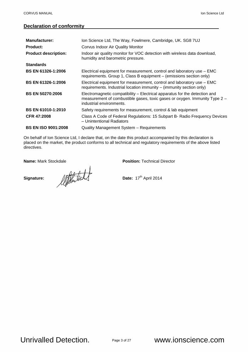
Declaration of conformity
Manufacturer: Ion Science Ltd, The Way, Fowlmere, Cambridge, UK. SG8 7UJ
Product: Corvus Indoor Air Quality Monitor
Product description: Indoor air quality monitor for VOC detection with wireless data download, humidity and barometric pressure.
Standards
BS EN 61326-1:2006 Electrical equipment for measurement, control and laboratory use – EMC requirements. Group 1, Class B equipment – (emissions section only)
BS EN 61326-1:2006 Electrical equipment for measurement, control and laboratory use – EMC requirements. Industrial location immunity – (immunity section only)
BS EN 50270:2006 Electromagnetic compatibility – Electrical apparatus for the detection and measurement of combustible gases, toxic gases or oxygen. Immunity Type 2 – industrial environments.
BS EN 61010-1:2010 Safety requirements for measurement, control & lab equipment
CFR 47:2008 Class A Code of Federal Regulations: 15 Subpart B- Radio Frequency Devices – Unintentional Radiators
BS EN ISO 9001:2008 Quality Management System – Requirements
On behalf of Ion Science Ltd, I declare that, on the date this product accompanied by this declaration is placed on the market, the product conforms to all technical and regulatory requirements of the above listed directives.
Name: Mark Stockdale Position: Technical Director
Signature:
Date: 17th April 2014
CORVUS MANUAL Ion Science Ltd
Page 4 of 27 Unrivalled Detection. www.ionscience.com
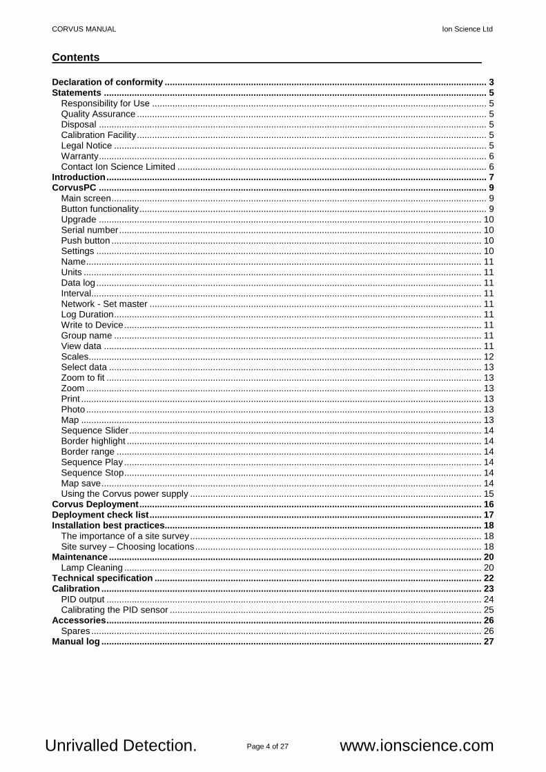
Contents
Declaration of conformity ............................................................................................................................... 3 Statements ....................................................................................................................................................... 5
Responsibility for Use .................................................................................................................................... 5 Quality Assurance .......................................................................................................................................... 5 Disposal ......................................................................................................................................................... 5 Calibration Facility .......................................................................................................................................... 5 Legal Notice ................................................................................................................................................... 5 Warranty ......................................................................................................................................................... 6 Contact Ion Science Limited .......................................................................................................................... 6
Introduction ...................................................................................................................................................... 7 CorvusPC ......................................................................................................................................................... 9
Main screen .................................................................................................................................................... 9 Button functionality ......................................................................................................................................... 9 Upgrade ....................................................................................................................................................... 10 Serial number ............................................................................................................................................... 10 Push button .................................................................................................................................................. 10 Settings ........................................................................................................................................................ 10 Name ............................................................................................................................................................ 11 Units ............................................................................................................................................................. 11 Data log ........................................................................................................................................................ 11 Interval.......................................................................................................................................................... 11 Network - Set master ................................................................................................................................... 11 Log Duration ................................................................................................................................................. 11 Write to Device ............................................................................................................................................. 11 Group name ................................................................................................................................................. 11 View data ..................................................................................................................................................... 11 Scales........................................................................................................................................................... 12 Select data ................................................................................................................................................... 13 Zoom to fit .................................................................................................................................................... 13 Zoom ............................................................................................................................................................ 13 Print .............................................................................................................................................................. 13 Photo ............................................................................................................................................................ 13 Map .............................................................................................................................................................. 13 Sequence Slider ........................................................................................................................................... 14 Border highlight ............................................................................................................................................ 14 Border range ................................................................................................................................................ 14 Sequence Play ............................................................................................................................................. 14 Sequence Stop ............................................................................................................................................. 14 Map save ...................................................................................................................................................... 14 Using the Corvus power supply ................................................................................................................... 15
Corvus Deployment ....................................................................................................................................... 16 Deployment check list ................................................................................................................................... 17 Installation best practices............................................................................................................................. 18
The importance of a site survey ................................................................................................................... 18 Site survey – Choosing locations ................................................................................................................. 18
Maintenance ................................................................................................................................................... 20 Lamp Cleaning ............................................................................................................................................. 20
Technical specification ................................................................................................................................. 22 Calibration ...................................................................................................................................................... 23
PID output .................................................................................................................................................... 24 Calibrating the PID sensor ........................................................................................................................... 25
Accessories .................................................................................................................................................... 26 Spares .......................................................................................................................................................... 26
Manual log ...................................................................................................................................................... 27
CORVUS MANUAL Ion Science Ltd
Page 5 of 27 Unrivalled Detection. www.ionscience.com
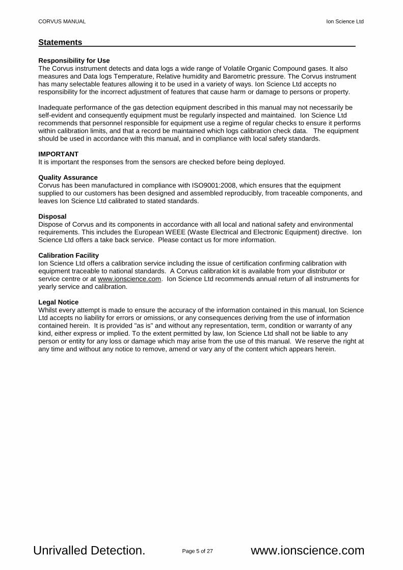
Statements
Responsibility for Use The Corvus instrument detects and data logs a wide range of Volatile Organic Compound gases. It also measures and Data logs Temperature, Relative humidity and Barometric pressure. The Corvus instrument has many selectable features allowing it to be used in a variety of ways. Ion Science Ltd accepts no responsibility for the incorrect adjustment of features that cause harm or damage to persons or property. Inadequate performance of the gas detection equipment described in this manual may not necessarily be self-evident and consequently equipment must be regularly inspected and maintained. Ion Science Ltd recommends that personnel responsible for equipment use a regime of regular checks to ensure it performs within calibration limits, and that a record be maintained which logs calibration check data. The equipment should be used in accordance with this manual, and in compliance with local safety standards. IMPORTANT It is important the responses from the sensors are checked before being deployed. Quality Assurance Corvus has been manufactured in compliance with ISO9001:2008, which ensures that the equipment supplied to our customers has been designed and assembled reproducibly, from traceable components, and leaves Ion Science Ltd calibrated to stated standards. Disposal Dispose of Corvus and its components in accordance with all local and national safety and environmental requirements. This includes the European WEEE (Waste Electrical and Electronic Equipment) directive. Ion Science Ltd offers a take back service. Please contact us for more information. Calibration Facility Ion Science Ltd offers a calibration service including the issue of certification confirming calibration with equipment traceable to national standards. A Corvus calibration kit is available from your distributor or service centre or at www.ionscience.com. Ion Science Ltd recommends annual return of all instruments for yearly service and calibration. Legal Notice Whilst every attempt is made to ensure the accuracy of the information contained in this manual, Ion Science Ltd accepts no liability for errors or omissions, or any consequences deriving from the use of information contained herein. It is provided "as is" and without any representation, term, condition or warranty of any kind, either express or implied. To the extent permitted by law, Ion Science Ltd shall not be liable to any person or entity for any loss or damage which may arise from the use of this manual. We reserve the right at any time and without any notice to remove, amend or vary any of the content which appears herein.

CORVUS MANUAL Ion Science Ltd
Page 6 of 27 Unrivalled Detection. www.ionscience.com
Statements
Warranty Standard Warranty can be extended to up to 2 years on the Corvus when registering your instrument via our website: www.ionscience.com/instrument-registration To receive your Extended Warranty, you need to register within one month of purchase (Terms and Conditions apply). You will then receive a confirmation email that your Extended Warranty Period has been activated and processed. Full details, along with a copy of our Warranty Statement can be found by visiting: www.ionscience.com/instrument-registration Contact Ion Science Limited
USA Office Ion Science Inc 4153 Bluebonnet Drive Stafford TX 77477 USA Tel: +1 (877) 864 7710 Fax: +1 802 244 8942 Email: [email protected] Web: www.ionscienceusa.com
UK Head Office Ion Science Ltd The Way, Fowlmere Cambridge SG8 7UJ UK Tel: +44 (0)1763 207206 Fax: +44 (0) 1763 208814 Email: [email protected]
Web: www.ionscience.com
German Office Ion Science Messtechnik GMBH Laubach 30 Metmann-Neandertal 40822 GERMANY Tel: +49 2104 14480 Fax: +49 2104 144825 Email: [email protected] Web: www.ism-d.de
CORVUS MANUAL Ion Science Ltd
Page 7 of 27 Unrivalled Detection. www.ionscience.com
Introduction Corvus is a Photo Ionisation Detector (PID) specifically designed to monitor VOC gas concentrations within indoor environments. It also logs temperature, relative humidity and barometric pressure to help diagnose potential sources of VOC’s. Multiple Corvus instruments communicate together via a low power wireless mesh network, this offers the convenience of downloading data from multiple slave instruments from a single Master instrument. CorvusPC software also offers a dynamic range of tools that make analysing data and creating reports quick and easy. Setup Please download and install Corvus PC software from the Ion Science website: http://www.ionscience.com/customer-support/instrument-software CorvusPC software is compatible with Microsoft Windows XP or later versions. IMPORTANT * All Corvus instruments are supplied setup as ‘Slave’ instruments with the Group name ‘A’. * To create a network of Corvus instruments a Master is required; any Corvus Slave can be setup as a Master using the CorvusPC software. Settings can be sent to multiple Corvus Slave instruments wirelessly via a Master if it shares the same network Group name. * Slave or Master Corvus instruments will not communicate with other Corvus instruments with different group names. Ion Science strongly recommends creating and testing a Corvus network before it is deployed. Connect Corvus to CorvusPC software Open CorvusPC software on a computer. Connect power to a Corvus instrument using the power adaptor supplied with the instrument. The LED on the Corvus will flash BLUE and RED. Use the USB cable from the accessory kit (Part number: A-877206) connect between the Corvus and the Computer. Failure to use the supplied USB cable may invalidate the EMC certificate. Corvus used in isolation. There may be applications where a network of instruments is not required or not possible. All Corvus instruments can be used in Isolation. Simply connect each Corvus to the CorvusPC software via the USB cable and set a unique Group name. Data will be stored in the Corvus instrument and must be downloaded via the USB connection. Corvus used in a network It is strongly recommended a network is setup and tested before deployment. When each Corvus is connected to CorvusPC for the first time a message will appear asking if this instrument is to be set as a Master. A Master instrument is required to control each group of up to 20 Corvus instruments. Data logging Data is stored on each Corvus and is transmitted to the Master of that group. Should wireless transmission be interrupted data will be stored on each Corvus and then forwarded to the master once wireless connection is regained. If wireless communication is permanently lost, data can be downloaded via USB from each Corvus instruments. CorvusPC recognises when an instrument is in a group and will collate data from separate instruments together. Data can therefore be viewed as if downloaded from a Master instrument.
CORVUS MANUAL Ion Science Ltd
Page 8 of 27 Unrivalled Detection. www.ionscience.com
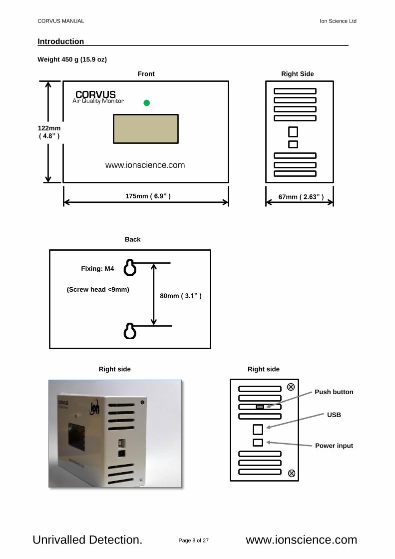
Front Right Side
Back
Introduction
Weight 450 g (15.9 oz)
www.ionscience.com
CORVUS Air Quality Monitor
122mm
( 4.8” )
175mm ( 6.9” ) 67mm ( 2.63” )
Push button
USB
Power input
Right side
Right side 80mm ( 3.1” )
Fixing: M4
(Screw head <9mm)
Right side
CORVUS MANUAL Ion Science Ltd
Page 9 of 27 Unrivalled Detection. www.ionscience.com
CorvusPC
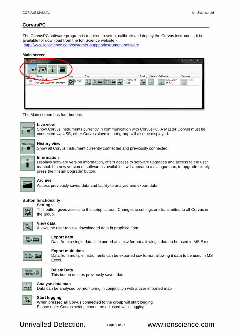
The CorvusPC software program is required to setup, calibrate and deploy the Corvus instrument; it is available for download from the Ion Science website:- http://www.ionscience.com/customer-support/instrument-software
Main screen
The Main screen has four buttons
Live view Show Corvus instruments currently in communication with CorvusPC. A Master Corvus must be connected via USB, other Corvus slave in that group will also be displayed.
History view
Show all Corvus instrument currently connected and previously connected. Information
Displays software version information, offers access to software upgrades and access to the user manual. If a new version of software is available it will appear in a dialogue box, to upgrade simply press the ‘Install Upgrade’ button.
Archive
Access previously saved data and facility to analyse and export data. Button functionality Settings
This button gives access to the setup screen. Changes to settings are transmitted to all Corvus in the group.
View data Allows the user to view downloaded data in graphical form Export data
Data from a single data is exported as a csv format allowing it data to be used in MS Excel.
Export multi data Data from multiple instruments can be exported csv format allowing it data to be used in MS Excel.
Delete Data This button deletes previously saved data .
Analyse data map Data can be analysed by monitoring in conjunction with a user imported map Start logging When pressed all Corvus connected to the group will start logging. Please note: Corvus setting cannot be adjusted while logging.
CORVUS MANUAL Ion Science Ltd
Page 10 of 27 Unrivalled Detection. www.ionscience.com
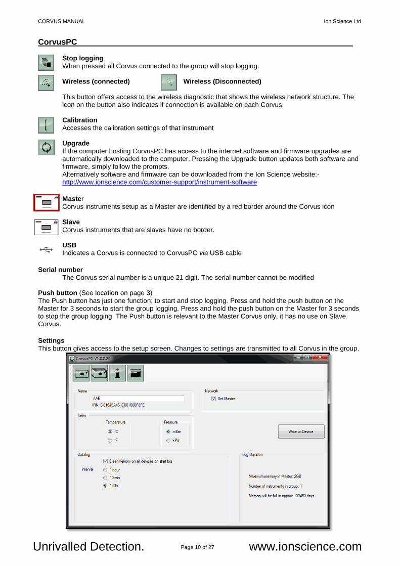
CorvusPC Stop logging When pressed all Corvus connected to the group will stop logging. Wireless (connected) Wireless (Disconnected)
This button offers access to the wireless diagnostic that shows the wireless network structure. The icon on the button also indicates if connection is available on each Corvus.
Calibration Accesses the calibration settings of that instrument
Upgrade If the computer hosting CorvusPC has access to the internet software and firmware upgrades are automatically downloaded to the computer. Pressing the Upgrade button updates both software and firmware, simply follow the prompts. Alternatively software and firmware can be downloaded from the Ion Science website:-
http://www.ionscience.com/customer-support/instrument-software
Master Corvus instruments setup as a Master are identified by a red border around the Corvus icon Slave Corvus instruments that are slaves have no border. USB Indicates a Corvus is connected to CorvusPC via USB cable
Serial number The Corvus serial number is a unique 21 digit. The serial number cannot be modified Push button (See location on page 3) The Push button has just one function; to start and stop logging. Press and hold the push button on the Master for 3 seconds to start the group logging. Press and hold the push button on the Master for 3 seconds to stop the group logging. The Push button is relevant to the Master Corvus only, it has no use on Slave Corvus.
Settings This button gives access to the setup screen. Changes to settings are transmitted to all Corvus in the group.
CORVUS MANUAL Ion Science Ltd
Page 11 of 27 Unrivalled Detection. www.ionscience.com
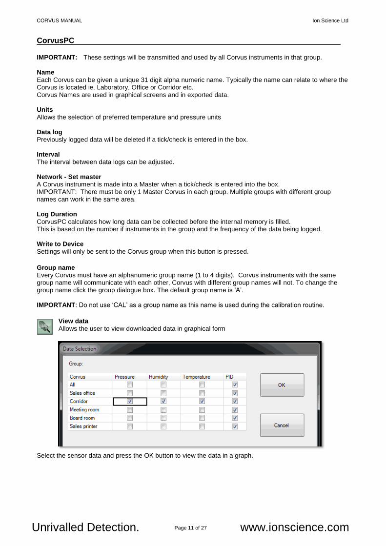
CorvusPC IMPORTANT: These settings will be transmitted and used by all Corvus instruments in that group. Name Each Corvus can be given a unique 31 digit alpha numeric name. Typically the name can relate to where the Corvus is located ie. Laboratory, Office or Corridor etc. Corvus Names are used in graphical screens and in exported data. Units Allows the selection of preferred temperature and pressure units Data log Previously logged data will be deleted if a tick/check is entered in the box. Interval The interval between data logs can be adjusted. Network - Set master A Corvus instrument is made into a Master when a tick/check is entered into the box. IMPORTANT: There must be only 1 Master Corvus in each group. Multiple groups with different group names can work in the same area. Log Duration CorvusPC calculates how long data can be collected before the internal memory is filled. This is based on the number if instruments in the group and the frequency of the data being logged. Write to Device
Settings will only be sent to the Corvus group when this button is pressed.
Group name Every Corvus must have an alphanumeric group name (1 to 4 digits). Corvus instruments with the same group name will communicate with each other, Corvus with different group names will not. To change the group name click the group dialogue box. The default group name is ‘A’. IMPORTANT: Do not use ‘CAL’ as a group name as this name is used during the calibration routine.
View data Allows the user to view downloaded data in graphical form
Select the sensor data and press the OK button to view the data in a graph.
CORVUS MANUAL Ion Science Ltd
Page 12 of 27 Unrivalled Detection. www.ionscience.com
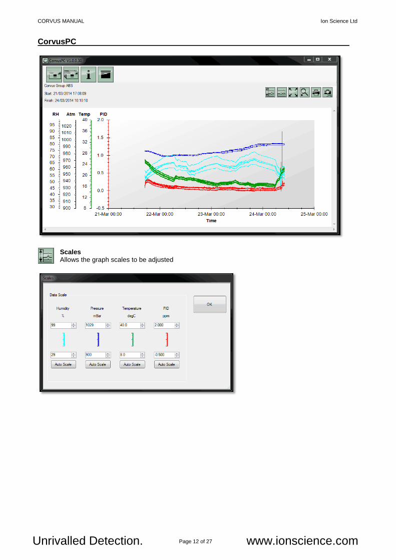
CorvusPC
Scales Allows the graph scales to be adjusted
CORVUS MANUAL Ion Science Ltd
Page 13 of 27 Unrivalled Detection. www.ionscience.com
CorvusPC
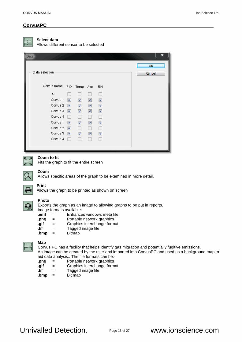
Select data Allows different sensor to be selected
Zoom to fit
Fits the graph to fit the entire screen
Zoom Allows specific areas of the graph to be examined in more detail.
Print Allows the graph to be printed as shown on screen
Photo Exports the graph as an image to allowing graphs to be put in reports.
Image formats available:- .emf = Enhances windows meta file .png = Portable network graphics .gif = Graphics interchange format .tif = Tagged image file .bmp = Bitmap Map Corvus PC has a facility that helps identify gas migration and potentially fugitive emissions. An image can be created by the user and imported into CorvusPC and used as a background map to aid data analysis.. The file formats can be:- .png = Portable network graphics .gif = Graphics interchange format .tif = Tagged image file .bmp = Bit map
CORVUS MANUAL Ion Science Ltd
Page 14 of 27 Unrivalled Detection. www.ionscience.com
CorvusPC
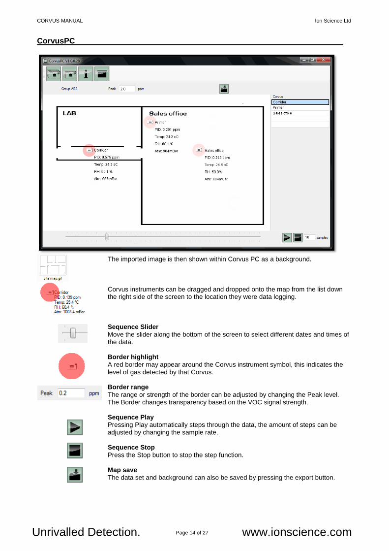
The imported image is then shown within Corvus PC as a background.
Corvus instruments can be dragged and dropped onto the map from the list down the right side of the screen to the location they were data logging.
Sequence Slider Move the slider along the bottom of the screen to select different dates and times of the data. Border highlight A red border may appear around the Corvus instrument symbol, this indicates the level of gas detected by that Corvus. Border range The range or strength of the border can be adjusted by changing the Peak level. The Border changes transparency based on the VOC signal strength. Sequence Play Pressing Play automatically steps through the data, the amount of steps can be adjusted by changing the sample rate.
Sequence Stop Press the Stop button to stop the step function. Map save The data set and background can also be saved by pressing the export button.

CORVUS MANUAL Ion Science Ltd
Page 15 of 27 Unrivalled Detection. www.ionscience.com
CorvusPC Using the Corvus power supply Power: Corvus is supplied with a 5 Volt dc universal power supply with plug adaptors that allow it to be connected to most types most domestic mains power outlets. The suitable plug adaptor must be connected to the power supply before it can be used. Power interruption: The Corvus has a battery backup allowing it to remember the date, time and which mode of operation it is in. If Corvus is logging when power is lost it will re-start logging after a ‘warm up’ time. The Corvus ‘warm up’ time will be up to 30 minutes depending on how long power is off. The battery back-up will maintain the time and settings for 1 month.
CORVUS MANUAL Ion Science Ltd
Page 16 of 27 Unrivalled Detection. www.ionscience.com
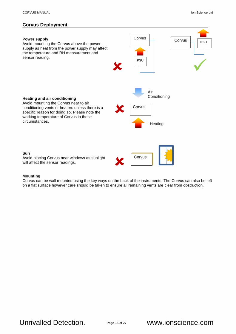
Corvus Deployment Power supply Avoid mounting the Corvus above the power supply as heat from the power supply may affect the temperature and RH measurement and sensor reading. Heating and air conditioning Avoid mounting the Corvus near to air conditioning vents or heaters unless there is a specific reason for doing so. Please note the working temperature of Corvus in these circumstances. Sun Avoid placing Corvus near windows as sunlight will affect the sensor readings. Mounting Corvus can be wall mounted using the key ways on the back of the instruments. The Corvus can also be left on a flat surface however care should be taken to ensure all remaining vents are clear from obstruction.
Corvus
Air Conditioning
Heating
Corvus
Corvus
PSU
Corvus PSU
CORVUS MANUAL Ion Science Ltd
Page 17 of 27 Unrivalled Detection. www.ionscience.com
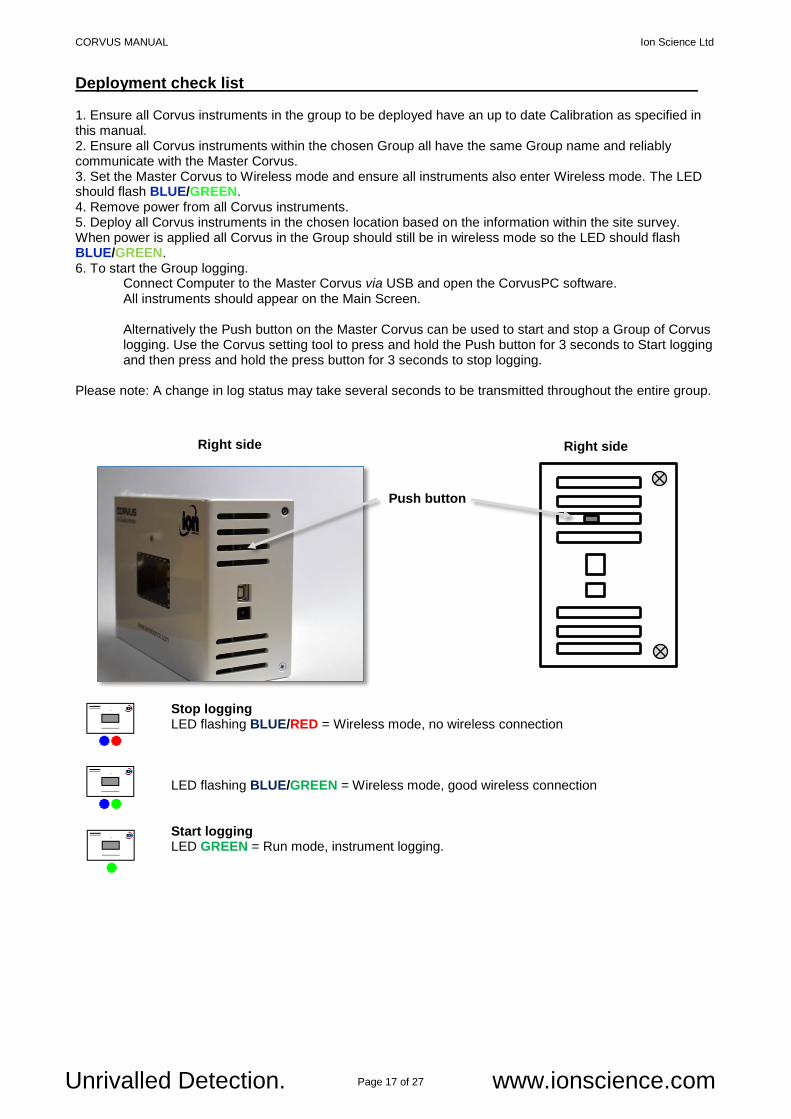
Deployment check list 1. Ensure all Corvus instruments in the group to be deployed have an up to date Calibration as specified in this manual. 2. Ensure all Corvus instruments within the chosen Group all have the same Group name and reliably communicate with the Master Corvus. 3. Set the Master Corvus to Wireless mode and ensure all instruments also enter Wireless mode. The LED should flash BLUE/GREEN. 4. Remove power from all Corvus instruments. 5. Deploy all Corvus instruments in the chosen location based on the information within the site survey. When power is applied all Corvus in the Group should still be in wireless mode so the LED should flash BLUE/GREEN. 6. To start the Group logging.
Connect Computer to the Master Corvus via USB and open the CorvusPC software. All instruments should appear on the Main Screen.
Alternatively the Push button on the Master Corvus can be used to start and stop a Group of Corvus logging. Use the Corvus setting tool to press and hold the Push button for 3 seconds to Start logging and then press and hold the press button for 3 seconds to stop logging.
Please note: A change in log status may take several seconds to be transmitted throughout the entire group.
Stop logging
LED flashing BLUE/RED = Wireless mode, no wireless connection LED flashing BLUE/GREEN = Wireless mode, good wireless connection Start logging LED GREEN = Run mode, instrument logging.
Push button
Right side Right side
CORVUS MANUAL Ion Science Ltd
Page 18 of 27 Unrivalled Detection. www.ionscience.com
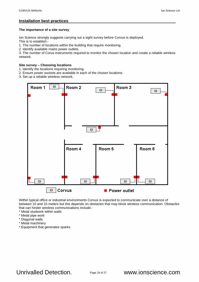
Installation best practices The importance of a site survey Ion Science strongly suggests carrying out a sight survey before Corvus is deployed. This is to establish:- 1. The number of locations within the building that require monitoring. 2. Identify available mains power outlets. 3. The number of Corus instruments required to monitor the chosen location and create a reliable wireless network.
Site survey – Choosing locations 1. Identify the locations requiring monitoring. 2. Ensure power sockets are available in each of the chosen locations. 3. Set up a reliable wireless network. Within typical office or industrial environments Corvus is expected to communicate over a distance of between 10 and 15 meters but this depends on obstacles that may block wireless communication. Obstacles that can hinder wireless communications include:- * Metal studwork within walls * Metal pipe work * Diagonal walls * Metal machinery * Equipment that generates sparks
CORVUS MANUAL Ion Science Ltd
Page 19 of 27 Unrivalled Detection. www.ionscience.com
Slave Master
Location 1
Location 1 Location 2 Wireless OK
Location 1 Location 2 No wireless connection
Location 1 Location 2 Link
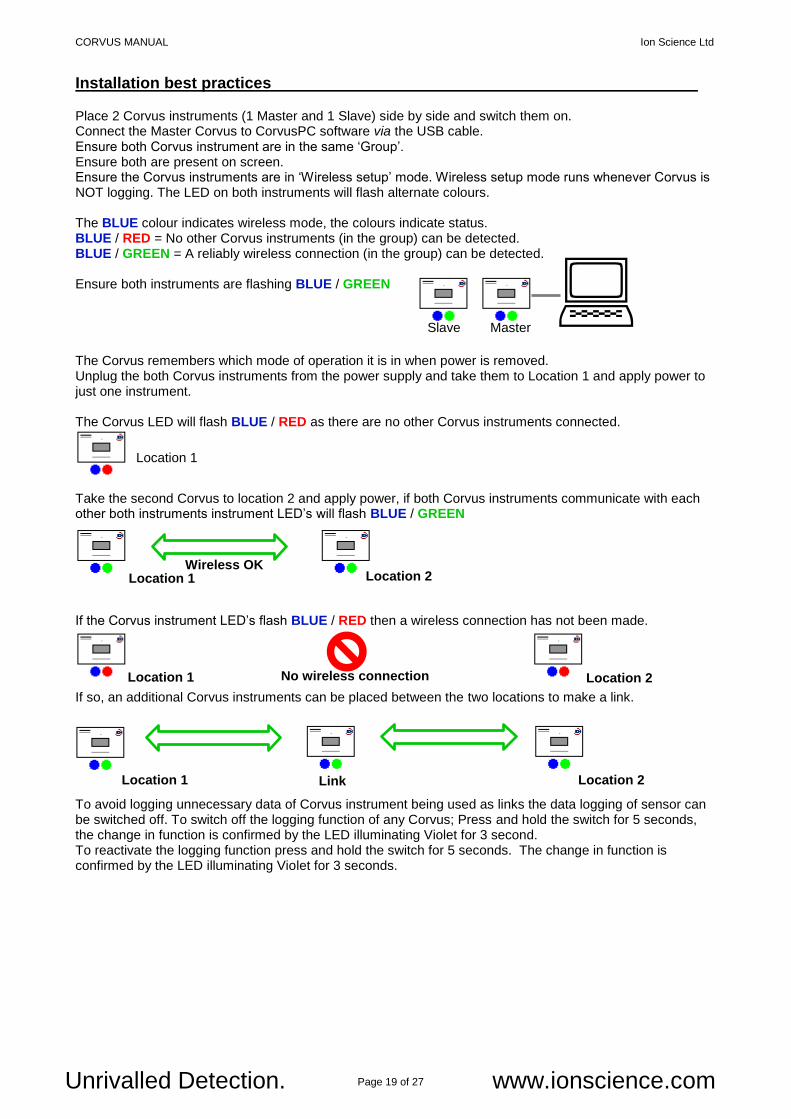
Installation best practices Place 2 Corvus instruments (1 Master and 1 Slave) side by side and switch them on. Connect the Master Corvus to CorvusPC software via the USB cable. Ensure both Corvus instrument are in the same ‘Group’. Ensure both are present on screen. Ensure the Corvus instruments are in ‘Wireless setup’ mode. Wireless setup mode runs whenever Corvus is NOT logging. The LED on both instruments will flash alternate colours. The BLUE colour indicates wireless mode, the colours indicate status. BLUE / RED = No other Corvus instruments (in the group) can be detected. BLUE / GREEN = A reliably wireless connection (in the group) can be detected. Ensure both instruments are flashing BLUE / GREEN The Corvus remembers which mode of operation it is in when power is removed. Unplug the both Corvus instruments from the power supply and take them to Location 1 and apply power to just one instrument. The Corvus LED will flash BLUE / RED as there are no other Corvus instruments connected. Take the second Corvus to location 2 and apply power, if both Corvus instruments communicate with each other both instruments instrument LED’s will flash BLUE / GREEN If the Corvus instrument LED’s flash BLUE / RED then a wireless connection has not been made. If so, an additional Corvus instruments can be placed between the two locations to make a link. To avoid logging unnecessary data of Corvus instrument being used as links the data logging of sensor can be switched off. To switch off the logging function of any Corvus; Press and hold the switch for 5 seconds, the change in function is confirmed by the LED illuminating Violet for 3 second. To reactivate the logging function press and hold the switch for 5 seconds. The change in function is confirmed by the LED illuminating Violet for 3 seconds.
CORVUS MANUAL Ion Science Ltd
Page 20 of 27 Unrivalled Detection. www.ionscience.com
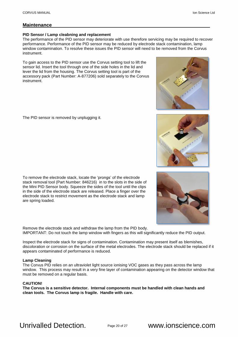
Maintenance PID Sensor / Lamp cleabning and replacement The performance of the PID sensor may deteriorate with use therefore servicing may be required to recover performance. Performance of the PID sensor may be reduced by electrode stack contamination, lamp window contamination. To resolve these issues the PID sensor will need to be removed from the Corvus instrument. To gain access to the PID sensor use the Corvus setting tool to lift the sensor lid. Insert the tool through one of the side holes in the lid and lever the lid from the housing. The Corvus setting tool is part of the accessory pack (Part Number: A-877206) sold separately to the Corvus instrument. The PID sensor is removed by unplugging it. To remove the electrode stack, locate the ‘prongs’ of the electrode stack removal tool (Part Number: 846216) in to the slots in the side of the Mini PID Sensor body. Squeeze the sides of the tool until the clips in the side of the electrode stack are released. Place a finger over the electrode stack to restrict movement as the electrode stack and lamp are spring loaded. Remove the electrode stack and withdraw the lamp from the PID body. IMPORTANT: Do not touch the lamp window with fingers as this will significantly reduce the PID output. Inspect the electrode stack for signs of contamination. Contamination may present itself as blemishes, discoloration or corrosion on the surface of the metal electrodes. The electrode stack should be replaced if it appears contaminated of performance is reduced. Lamp Cleaning The Corvus PID relies on an ultraviolet light source ionising VOC gases as they pass across the lamp window. This process may result in a very fine layer of contamination appearing on the detector window that must be removed on a regular basis. CAUTION! The Corvus is a sensitive detector. Internal components must be handled with clean hands and clean tools. The Corvus lamp is fragile. Handle with care.
CORVUS MANUAL Ion Science Ltd
Page 21 of 27 Unrivalled Detection. www.ionscience.com
Maintenance Inspection of the lamp may reveal a layer of contamination on the detection window that presents itself as a ‘blue hue.’ To check for confirmation, hold the lamp in front of a light source and look across the window surface. Clean the window using the PID Lamp Cleaning Kit (A-31063) supplied. USE of PID Lamp Cleaning Kit A-31063 The container of cleaning compound contains Aluminium Oxide as a very fine power (CAS Number 1344-28-1). A full material safety data sheet MSDS is available on request from Ion Science Ltd. The key issues are listed below: Always replace the lid after using the cleaning compound. Hazard identification:
May cause irritation of respiratory tract and eyes. Handling:
Do not breathe vapour / dust. Avoid contact with skin, eyes and clothing;
Wear suitable protective clothing;
Follow industrial hygiene practices: Wash face and hands thoroughly with soap and water after use and before eating, drinking, smoking or applying cosmetics;
The Compound has a TVL (TWA) of 10 mg/m3. Storage:
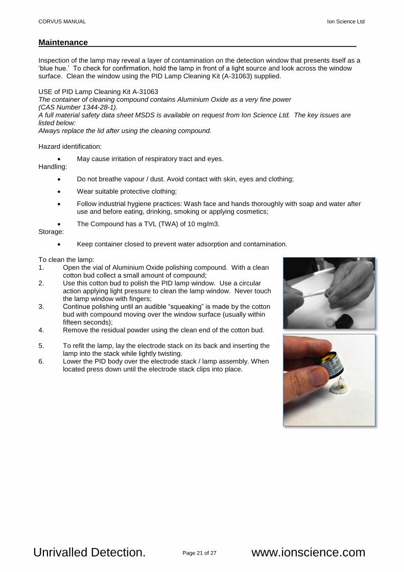
Keep container closed to prevent water adsorption and contamination. To clean the lamp: 1. Open the vial of Aluminium Oxide polishing compound. With a clean
cotton bud collect a small amount of compound; 2. Use this cotton bud to polish the PID lamp window. Use a circular
action applying light pressure to clean the lamp window. Never touch the lamp window with fingers;
3. Continue polishing until an audible “squeaking” is made by the cotton bud with compound moving over the window surface (usually within fifteen seconds);
4. Remove the residual powder using the clean end of the cotton bud. 5. To refit the lamp, lay the electrode stack on its back and inserting the
lamp into the stack while lightly twisting. 6. Lower the PID body over the electrode stack / lamp assembly. When
located press down until the electrode stack clips into place.
CORVUS MANUAL Ion Science Ltd
Page 22 of 27 Unrivalled Detection. www.ionscience.com
Technical specification Dimensions
Size: H. 122 mm (4.8 in) W. 176 mm (6.9 in) D. 68 mm (2.6 in) Weight 450 g (15.9 oz.)
Sensitivity
PID 5 ppb (Isobutylene equivalent) Temperature 0.1
oC ( 0.18
oF)
Relative humidity 0.04% Barometric pressure 0.72 mbar (72 Pa) (0.2% full scale)
Detection range
PID 0-50 ppm (Isobutylene equivalent) Temperature -40
oC to +125
oC (-40
oF to 257
oF)
Relative humidity 0-99% (non-condensing) Barometric pressure 700 mbar to 1060 mbar (70 kPa to 106 kPa)
Accuracy PID +/- 5 ppb displayed reading + 1 digit Temperature +/- 1
oC of reading + 1 digit
Relative humidity +/- 4% of reading + 1 digit (@25
oC between 10% and 90% RH)
Barometric pressure +/- 1.5% displayed reading + 1 digit (FSO) Wireless network
Type Mesh Maximum open field range Up to 12 m (39 Ft) Number of Corvus in a group 20 Max Wireless frequency 2.4 MHz
Data log Data logging 18755 points (individual Corvus) Data logging 8900 points (Network of 20 Corvus) Data log options 1 min, 10 min and 1 hr.
Power Mains power supply 100-240 Vac (15 Watts) Corvus power input 5 Vdc
Communication
Corvus to PC USB 2.1 Corvus to Corvus Wireless via network
CORVUS MANUAL Ion Science Ltd
Page 23 of 27 Unrivalled Detection. www.ionscience.com
Calibration Calibration
Note: Please read the entire procedure before beginning the calibration process. Preparation: For best results Ion Science recommends the following equipment is used to Calibrate Corvus:-
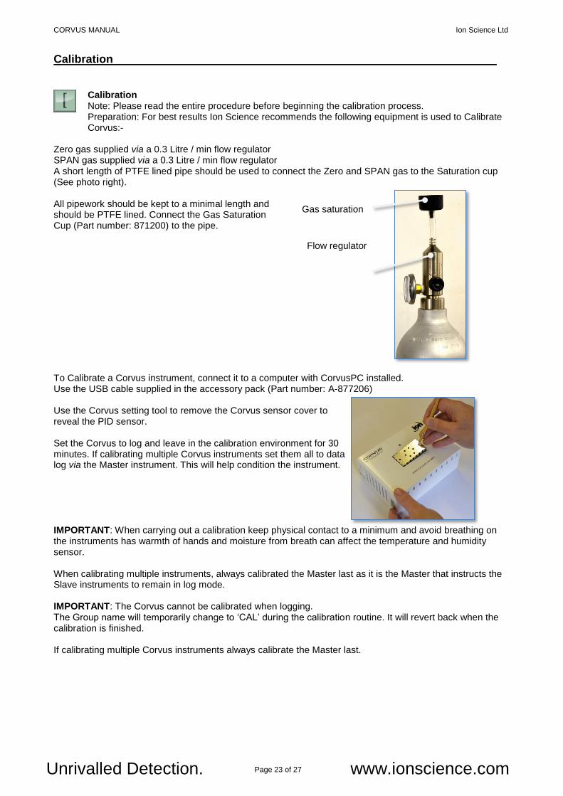
Zero gas supplied via a 0.3 Litre / min flow regulator SPAN gas supplied via a 0.3 Litre / min flow regulator A short length of PTFE lined pipe should be used to connect the Zero and SPAN gas to the Saturation cup (See photo right).
All pipework should be kept to a minimal length and should be PTFE lined. Connect the Gas Saturation Cup (Part number: 871200) to the pipe.
To Calibrate a Corvus instrument, connect it to a computer with CorvusPC installed. Use the USB cable supplied in the accessory pack (Part number: A-877206)
Use the Corvus setting tool to remove the Corvus sensor cover to reveal the PID sensor.
Set the Corvus to log and leave in the calibration environment for 30 minutes. If calibrating multiple Corvus instruments set them all to data log via the Master instrument. This will help condition the instrument.
IMPORTANT: When carrying out a calibration keep physical contact to a minimum and avoid breathing on the instruments has warmth of hands and moisture from breath can affect the temperature and humidity sensor. When calibrating multiple instruments, always calibrated the Master last as it is the Master that instructs the Slave instruments to remain in log mode. IMPORTANT: The Corvus cannot be calibrated when logging. The Group name will temporarily change to ‘CAL’ during the calibration routine. It will revert back when the calibration is finished. If calibrating multiple Corvus instruments always calibrate the Master last.
Gas saturation cup
Flow regulator
CORVUS MANUAL Ion Science Ltd
Page 24 of 27 Unrivalled Detection. www.ionscience.com
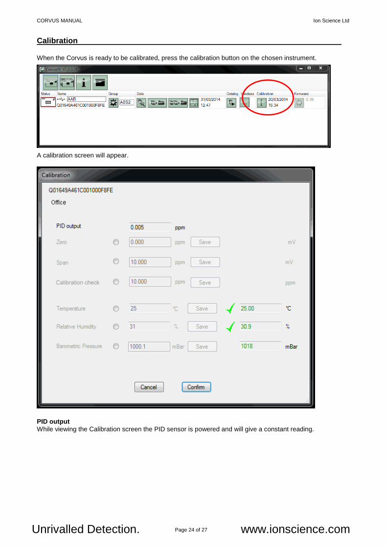
Calibration When the Corvus is ready to be calibrated, press the calibration button on the chosen instrument. A calibration screen will appear.
PID output While viewing the Calibration screen the PID sensor is powered and will give a constant reading.
CORVUS MANUAL Ion Science Ltd
Page 25 of 27 Unrivalled Detection. www.ionscience.com
Calibration
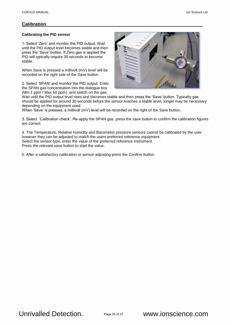
Calibrating the PID sensor 1. Select ‘Zero’ and monitor the PID output. Wait until the PID output level becomes stable and then press the ‘Save’ button. If Zero gas is applied the PID will typically require 30 seconds to become stable. When Save is pressed a millivolt (mV) level will be recorded on the right side of the Save button. 2. Select ‘SPAN’ and monitor the PID output. Enter the SPAN gas concentration into the dialogue box (Min 1 ppm / Max 50 ppm) and switch on the gas. Wait until the PID output level rises and becomes stable and then press the ‘Save’ button. Typically gas should be applied for around 30 seconds before the sensor reaches a stable level, longer may be necessary depending on the equipment used. When ‘Save’ is pressed, a millivolt (mV) level will be recorded on the right of the Save button. 3. Select ‘Calibration check’. Re-apply the SPAN gas, press the save button to confirm the calibration figures are correct. 4. The Temperature, Relative humidity and Barometric pressure sensors cannot be calibrated by the user however they can be adjusted to match the users preferred reference equipment. Select the sensor type, enter the value of the preferred reference instrument. Press the relevant save button to start the value. 5. After a satisfactory calibration or sensor adjusting press the Confirm button.
CORVUS MANUAL Ion Science Ltd
Page 26 of 27 Unrivalled Detection. www.ionscience.com
Accessories
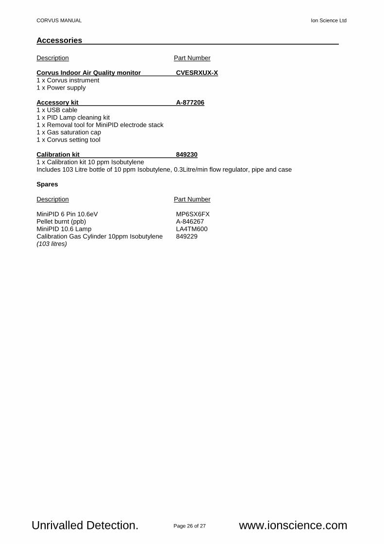
Description Part Number Corvus Indoor Air Quality monitor CVESRXUX-X 1 x Corvus instrument 1 x Power supply Accessory kit A-877206 1 x USB cable 1 x PID Lamp cleaning kit 1 x Removal tool for MiniPID electrode stack 1 x Gas saturation cap 1 x Corvus setting tool Calibration kit 849230 1 x Calibration kit 10 ppm Isobutylene Includes 103 Litre bottle of 10 ppm Isobutylene, 0.3Litre/min flow regulator, pipe and case Spares Description Part Number MiniPID 6 Pin 10.6eV MP6SX6FX Pellet burnt (ppb) A-846267 MiniPID 10.6 Lamp LA4TM600 Calibration Gas Cylinder 10ppm Isobutylene 849229 (103 litres)

CORVUS MANUAL Ion Science Ltd
Page 27 of 27 Unrivalled Detection. www.ionscience.com
Manual log
Manual Version Amendment Issue Date
Corvus Manual V1.0
Manual created 17/04/2014

![Part Count: Corvus [OR-K-CV1], 20’ x 20’ Kit Sizeimavex.vo.llnwd.net › ... › files › Corvus-OR-K-CV1.pdfGraphic Specs: Corvus [OR-K-CV1], 20’ x 20’ Kit Size IMPORTANT](https://img.pdfslide.net/doc/110x75/5f1599ff16e0113abc363bf7/part-count-corvus-or-k-cv1-20a-x-20a-kit-a-a-files-a-corvus-or-k-cv1pdf.jpg)


![Corvus by Satyajit Roy[English]](https://img.pdfslide.net/doc/110x75/553e77be4a795905308b4966/corvus-by-satyajit-royenglish.jpg)