Embed Size (px)
Citation preview

Instrumentation and Controls
90-863758070 APRIL 2008 Page 9A-1
9A
Instrumentation and ControlsSection 9A - Instrumentation and Controls
Table of Contents
Instrumentation................................................9A-2Requirements and Recommendations.....9A-2Important Installation Information.............9A-2Accessory Connections............................9A-3Dual Station Instrumentation....................9A-3Engine Guardian System..........................9A-4Lanyard Stop Switch Information..............9A-4Boat Harness............................................9A-6Instrumentation Harness Receptacle........9A-814‑Pin Engine—Analog Gauge Harness..................................................................9A-914‑Pin Engine Harness Connector.........9A-10
Remote Control and Cables...........................9A-10Requirements and Recommendations. . .9A-10
Installation...............................................9A-11Dual Station (Helm) Cable Setup............9A-12Cable Attachment Hardware...................9A-13Cable Adjustment...................................9A-15
Motoviewer.....................................................9A-17MotoViewer Service Tool........................9A-17Saving Special Functions.......................9A-18Clearing Fault History.............................9A-18Setting Engine Location..........................9A-19AutoSync................................................9A-20Trim and Trailer Limit..............................9A-21Configuring EZLink Gauges (TachLink)................................................................9A-25Other Special Functions.........................9A-26
Instrumentation and Controls
Page 9A-2 90-863758070 APRIL 2008
Lubricant, Sealant, AdhesivesTube Ref No. Description Where Used Part No.
25 Liquid Neoprene Electrical connections 92- 25711 3
95 2-4-C with Teflon Cable guides and pivot points 92-802859A 1
InstrumentationRequirements and Recommendations
IMPORTANT: This section includes information on Quicksilver's standard (non‑digital)instrumentation and mechanical (cable‑actuated) remote controls. Refer to the Smart Craftapplications manual for information on Mercury's new digital instrumentation and remotecontrols.Mercury MerCruiser inboard and tow sports engines, designed to comply with the ABYCStandards, use the four basic gauges shown below:• Tachometer• Oil pressure• Water temperature• Voltmeter (battery charge indicator)An extensive array of Quicksilver gauges, instrumentation harnesses, extensionharnesses, and related accessories are available through Mercury Precision Parts tosatisfy your instrumentation needs. We recommend the use of Quicksilver instrumentationbecause they are specifically designed for compatibility with our engines, and engineeredto the same high quality and performance standards. Refer to the Mercury Precision PartsAccessories Guide for a complete list. Wiring diagrams of some of the basic instrumentationconfigurations are provided at the end of this section.
Important Installation InformationInstrumentation should be installed in accordance with the instructions that accompanythem.IMPORTANT: When designing and installing the instrumentation, adhere to the applicableboating industry standards and regulations (NMMA, ABYC, SAE, USCG, EUs, RCD, ISO,etc.) for the markets where the boat will be sold.• Ensure that harnesses are routed to avoid getting pinched or chafed.• Avoid routing the harness in an area where it could be damaged or short circuited later
in the assembly process, such as when a screw is inserted or a hole is drilled.IMPORTANT: Harness receptacles can be damaged by overtightening clamps.• The cannon plug connection on the extension harness (at engine and dash) must be
secured with a hose clamp to avoid a loose connection or water entry.• Support harness every 46 cm (18 in.) using industry approved fasteners. (ABYC
Standard)• Coat exposed connections on gauges with liquid neoprene to avoid corrosion.
Tube Ref No. Description Where Used Part No.
25 Liquid Neoprene Electrical connections 92- 25711 3
Instrumentation and Controls
90-863758070 APRIL 2008 Page 9A-3
Accessory Connections
! CAUTIONFailure to protect wiring with an appropriate fuse can damage the wiring and start a fire.When installing any accesories, we recommend using a Mercury accessory kit. Alwaysuse the appropriate fuse to protect wiring.
! CAUTIONFailure to protect wiring with an appropriate fuse can damage the wiring and start a fire.When installing any accesories, we recommend using a Mercury accessory kit. Alwaysuse the appropriate fuse to protect wiring.
IMPORTANT: The accessory wire in the 14‑pin harness will not support amperage inexcess of 15‑amps. For protection, the main power relay fuse may blow if an excess of15‑amps is applied. Refer to the Mercury Precision Parts Accessories Guide for an optionalaccessory power relay kit that will accommodate higher amperage draw.A fused accessory panel with up to a 40‑amp current draw can be connected to the helmharness. On dual station applications, the combined current draw for both stations mustnot exceed 40 amps. If optional accessory power relay kits are installed, the combinedcurrent draw for both stations must not exceed 40 amps per kit. Each helm harness maysupport up to two accessory power relay kits. The boat manufacturer is responsible forensuring that the accessory connections are made in accordance with the industrystandards and regulations. See information under Industry Standards andRegulations.
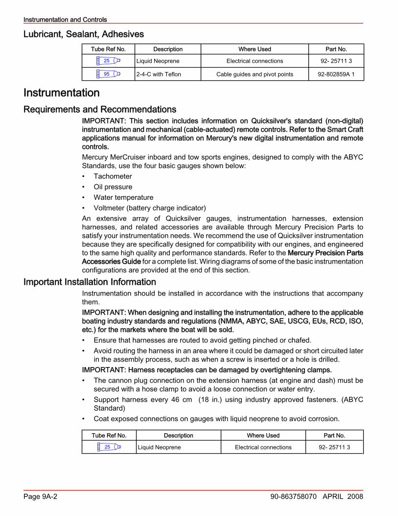
Dual Station InstrumentationInstrumentation and harnesses are available through Mercury Precision Parts andAccessories to accommodate dual station (helm) applications (see wiring diagram fortypical installation). When oil pressure and water temperature gauges are used at bothstations, dual station oil pressure and temperature senders must be installed on the engineto obtain the proper gauge readings. Refer to theMercury Precision Parts and AccessoriesGuide for part numbers.
a
15528
a - Typical coolant temperature sender

Instrumentation and Controls
Page 9A-4 90-863758070 APRIL 2008
a
15529
a - Typical oil pressure sender
Engine Guardian SystemThe Engine Guardian System monitors the critical sensors on the engine for any earlyindications of problems. The system will respond to a problem by emitting a continuousbeep and/or reducing engine power in order to provide engine protection.If Guardian System has been activated, reduce throttle speed. The horn will turn off whenthrottle speed is within the allowable limit. Consult an authorized Mercury MerCruiserdealer for assistance.
Lanyard Stop Switch Information
! WARNINGAvoid serious injury or death from deceleration forces resulting from accidental orunintended stop switch activation. The boat operator should never leave the operator'sstation without first disconnecting the stop switch lanyard from the operator.
74608
RUN ab
c
a - Stop switchb - Lanyard
c - Clips to operator
The purpose of a lanyard stop switch is to turn off the engine when the operator movesoutside the operator's position (as in accidental ejection from the operator's position).Accidental ejections, such as falling overboard, are more likely to occur in:• low sided sport boats.• bass boats.• high‑performance boats.Accidental ejections can also occur from:• following poor operating practices.• sitting on the seat or gunwale at planing speeds.
Instrumentation and Controls
90-863758070 APRIL 2008 Page 9A-5
• standing at planing speeds.• operating the boat at planing speeds in shallow or obstacle infested waters.• releasing your grip on the steering wheel while it is pulling in one direction.• consuming alcohol or drugs.• maneuvering the boat at high speeds.Some remote control units are equipped with a lanyard stop switch. If your remote controlis not equipped with a lanyard stop switch, one can be installed on the dashboard or sideadjacent to the operator's position. The lanyard is a cord usually 1.2–1.5 m (4–5 ft.) longwhen stretched out with an element on one end made to be inserted into the switch and asnap on the other end for attaching to the operator. The lanyard is coiled to make it as shortas possible to minimize the likelihood of entanglement with nearby objects. It stretches tominimize the likelihood of accidental activation should the operator choose to move aroundin an area close to the normal operator's position. If it is desired to have a shorter lanyard,wrap the lanyard around the operator's wrist or leg or tie a knot in the lanyard.While activation of the lanyard stop switch will stop the engine immediately, the boat willcontinue to coast for some distance depending upon the velocity and degree of any turnat shut‑down. However, the boat will not complete a full circle. While the boat is coasting,it can cause injury to anyone in the boat's path as seriously as the boat would when underpower.We strongly recommend that other occupants be instructed on proper starting andoperating procedures should they be required to operate the engine in an emergency (e.g.if the operator is ejected).
! WARNINGIf the operator falls out of the boat, stop the engine immediately to reduce the possibilityof serious injury or death from being struck by the boat. Always properly connect theoperator to the stop switch using a lanyard.
Accidental or unintended activation of the switch during normal operation is also apossibility. This could cause any, or all, of the following potentially hazardous situations:• Occupants could be thrown forward due to unexpected loss of forward motion, a
particular concern for passengers in the front of the boat who could be ejected over thebow and possibly struck by the gear case or propeller.
• Loss of power and directional control in heavy seas, strong current, or high winds.• Loss of control when docking.

Instrumentation and Controls
Page 9A-6 90-863758070 APRIL 2008
Boat HarnessDRAWING
12340
1
7
8
1011
9
2
3
4
56
1 - 14‑pin Deutsch connector2 - Key switch connector3 - Trim switch (outboard only)4 - Neutral switch5 - Lanyard switch (sterndrive) or key
switch + connection6 - Lanyard (outboard) or E Stop
connection
7 - Warning horn8 - Accessory relay connection
(15‑amp)9 - Gauge connector/CAN connector
for SmartCraft10 - CAN P (1) with resistor cap11 - CAN V (3) with weather cap

Instrumentation and Controls
90-863758070 APRIL 2008 Page 9A-7
DIAGRAM
1
RED
RED
RED
RED
RED
RED
BLK
BLK
BLK
BLK
BLK
PPL
PPL
BLK_YEL
BLK_YEL
ORG
ORG
WHT
WHT
DKBLU
DKBLU
BLU_WHT
BLU_WHT
GRN_WHT
GRN_WHT
YEL
YEL
BRN
BRN
GRY
GRY
YEL_RED
YEL_RED
GRN
GRN
BLKBLK
PPL
PPL
BLK_YEL
PPL_WHT
PPL_WHT
YEL_RED
YEL_RED
PPL
PPL
PPL_WHT
GRN
ORG
WHT
DKBL
U
AB
CD
EF
GH
JK
LM
NP
AB
CD
EF
GH
JK
AB
C
AB
CD
EF
AB
C1
1
1
1
1
A B A B
A B A B
1
1
1
2
3
5
8
9
1011
4
6
7
12339
1 - 14‑pin Deutsch connector2 - Key switch connector3 - Trim switch (outboard only)4 - Neutral switch5 - Lanyard switch (sterndrive) or key
switch + connection6 - Lanyard (outboard) or E Stop
connection
7 - Warning horn8 - Accessory relay connection
(15‑amp)9 - Gauge connector10 - CAN P (1) with resistor cap11 - CAN V (3) with weather cap
NOTE: Dual engines are treated as 2 singles in the same boat and are only connected bya CAN 1 link harness.NOTE: The lanyard stop switch (PPL and PPL/WHT wires) breaks power to the ECM orignition to stop the engine. The switch is normally closed until activated. Therefore the PPLand PPL/WHT wires must be connected together if Lanyard Stop Switch is not used, or ifthe E Stop Switch is used.NOTE: E Stop Switch (BLK and BLK/YEL wires) connects ground to ECM to stop engine.The switch is normally open, the circuit closes when switch is activated. Wires must beseparate unless connected through E Stop Switch.
Instrumentation and Controls
Page 9A-8 90-863758070 APRIL 2008
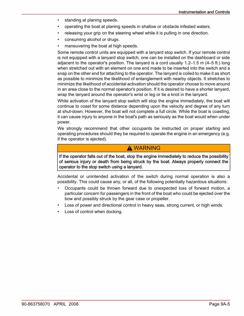
Instrumentation Harness ReceptacleIMPORTANT: Loose or corroded harness connectors are a common source for enginemalfunctions.
a
bcd
e
12118
Typical 14‑pin DTS harness without Emissions Controla - Engine harness connectorb - Transmission harness connectorc - Paddle wheel/tank level connector
d - DLC/depth transducer connectore - Power harness connector/clean
power with 5‑amp fuse (DTS andPCM09 only)
a
b c d e 32503
a - Transom harness connectorb - Paddle wheel and tank level
connectorc - Diagnostic connector
d - Power harness connectore - 14‑pin harness connector

Instrumentation and Controls
90-863758070 APRIL 2008 Page 9A-9
14‑Pin Engine—Analog Gauge Harness
12312
8
910
23456
71
1 - Connector to boat harness2 - Trim3 - Tach4 - Key on (+)5 - Temp
6 - Oil7 - Ground (‑)8 - Can (+) or spare9 - Can (‑) or spare10 - 12V (+)
RED
RED
DK_BLU
DK_BLU
WHT
WHT
BLK BLKLTBLU
LTBLUTAN
TAN
PPL
PPL
GRY
GRY
BRN_WHT
BRN_WHT
AB
CD
EF
GH
JK
12318
1
234567
8
9
10
1 - Connector to boat harness2 - Trim3 - Tach4 - Key on (+)5 - Temp
6 - Oil7 - Ground (‑)8 - Can (+) or spare9 - Can (‑) or spare10 - 12V (+)
Accessory power can be provided up to 15 amps total; on purple wire (switched) and redwire (continuous power.)An accessory relay kit can be used for loads up to 40 amps. Refer to MerCruiser Parts andAccessory Guide or MerCruiser Rigging Guide

Instrumentation and Controls
Page 9A-10 90-863758070 APRIL 2008
14‑Pin Engine Harness ConnectorMechanical 14‑Pin Connector Pin‑Out
Pin Wire Color FunctionA PINK + 12 VoltB BLACK Ground (‑)C PURPLE WakeD DK GREEN/YELLOW E‑StopE DK BLUE Analog oil pressureF WHITE CAN 1+G LT BLUE CAN 1‑H Open SpareJ Open SpareK ORANGE/WHITE Analog trim positionL BROWN/DK BLUE Audio warning hornM GRAY/WHITE Tachometer/Link gaugeN YELLOW/BLACK CrankP TAN Analog coolant temperature
Remote Control and CablesRequirements and Recommendations
We recommend using Quicksilver remote controls, which have been specifically designedfor compatibility with our engines, and to the same high quality and performance standards.An extensive array of Quicksilver remote controls and cables are available through theMercury Precision Parts Accessories Guide.A single lever control (shift and throttle function in same lever) or a two‑lever control(separate shift and throttle levers) can be used on single station applications. Two‑levercontrols are required on dual station (helm) applications.• Remote control must provide a cable travel (at engine end).
Remote Control Cable Travel
Function Travel [with 6.8-9 kg (15-20 lb.) load applied]
Shift 70– 80 mm (2‑3/4–3‑1/8 in.)Throttle 70–80 mm (2‑3/4–3‑1/8 in.)
• The remote control must be set up to retract the shift cable when going into FORWARDgear on Velvet Drive 71C and 72C in‑line transmissions. On Velvet Drive 5000 and allHurth transmissions, shift cable actuation must be set up to achieve the desiredpropeller rotation. See information in Section 2 - Transmission and Drive Line.
NOTICEIncorrect positioning of the transmission shift lever can cause transmission failure. Thespring‑loaded poppet ball helps the transmission shift lever to stay in place. Do notremove the poppet ball or spring.
• The remote control must be set up to fully extend the throttle cable for idle.• A neutral start safety switch is included in the transmission. The switch in the remote
control should not be used.
Instrumentation and Controls
90-863758070 APRIL 2008 Page 9A-11
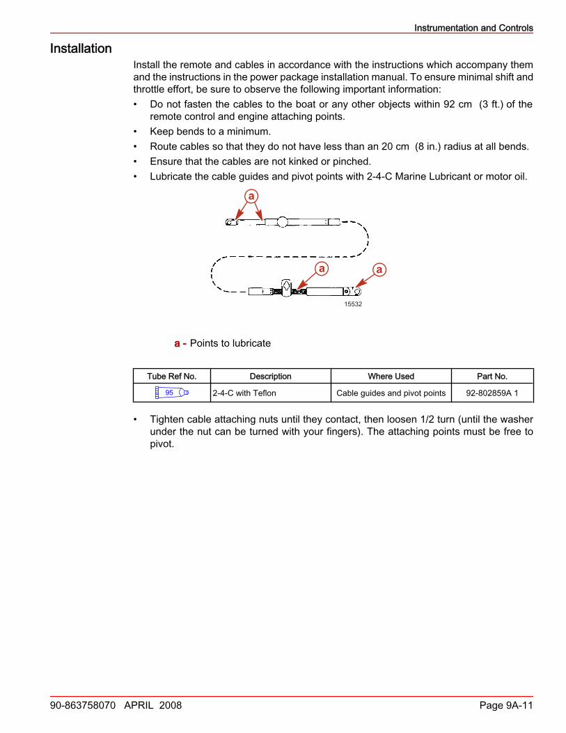
InstallationInstall the remote and cables in accordance with the instructions which accompany themand the instructions in the power package installation manual. To ensure minimal shift andthrottle effort, be sure to observe the following important information:• Do not fasten the cables to the boat or any other objects within 92 cm (3 ft.) of the
remote control and engine attaching points.• Keep bends to a minimum.• Route cables so that they do not have less than an 20 cm (8 in.) radius at all bends.• Ensure that the cables are not kinked or pinched.• Lubricate the cable guides and pivot points with 2‑4‑C Marine Lubricant or motor oil.
15532
a
a a
a - Points to lubricate
Tube Ref No. Description Where Used Part No.
95 2-4-C with Teflon Cable guides and pivot points 92-802859A 1
• Tighten cable attaching nuts until they contact, then loosen 1/2 turn (until the washerunder the nut can be turned with your fingers). The attaching points must be free topivot.
Instrumentation and Controls
Page 9A-12 90-863758070 APRIL 2008
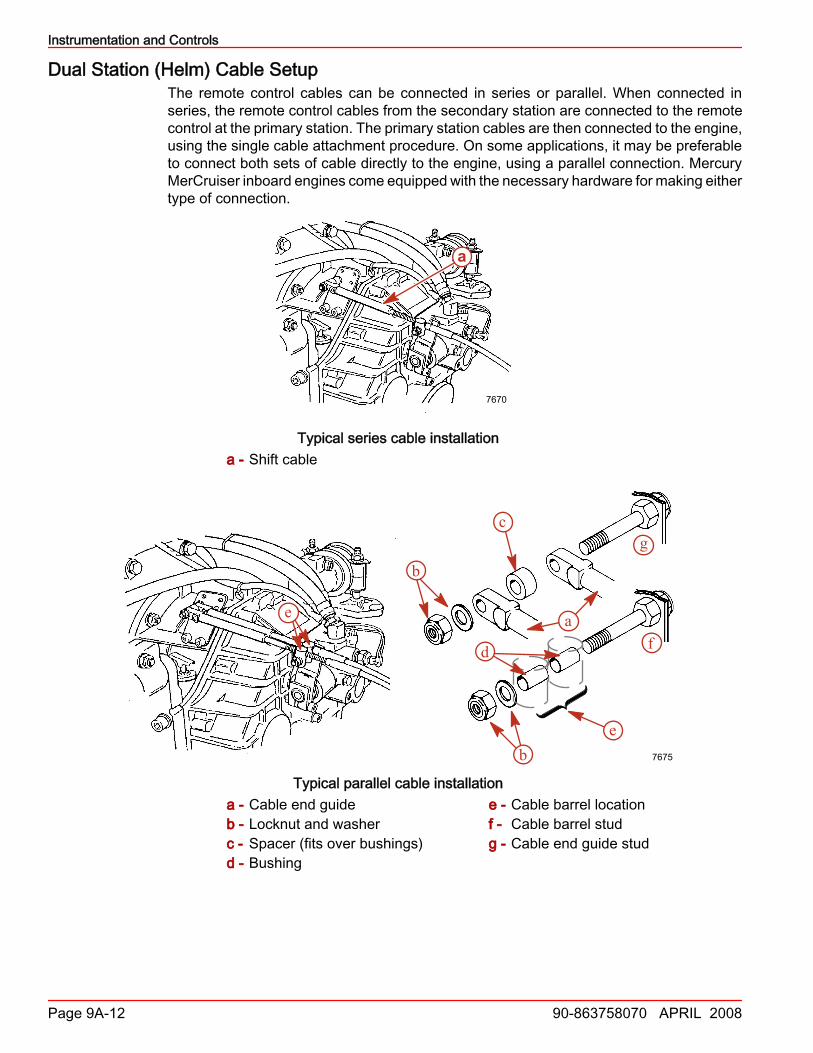
Dual Station (Helm) Cable SetupThe remote control cables can be connected in series or parallel. When connected inseries, the remote control cables from the secondary station are connected to the remotecontrol at the primary station. The primary station cables are then connected to the engine,using the single cable attachment procedure. On some applications, it may be preferableto connect both sets of cable directly to the engine, using a parallel connection. MercuryMerCruiser inboard engines come equipped with the necessary hardware for making eithertype of connection.
a
7670
Typical series cable installationa - Shift cable
e a
b
c
d
eb
f
g
7675
Typical parallel cable installationa - Cable end guideb - Locknut and washerc - Spacer (fits over bushings)d - Bushing
e - Cable barrel locationf - Cable barrel studg - Cable end guide stud
Instrumentation and Controls
90-863758070 APRIL 2008 Page 9A-13
Cable Attachment HardwareINBOARD MODELS
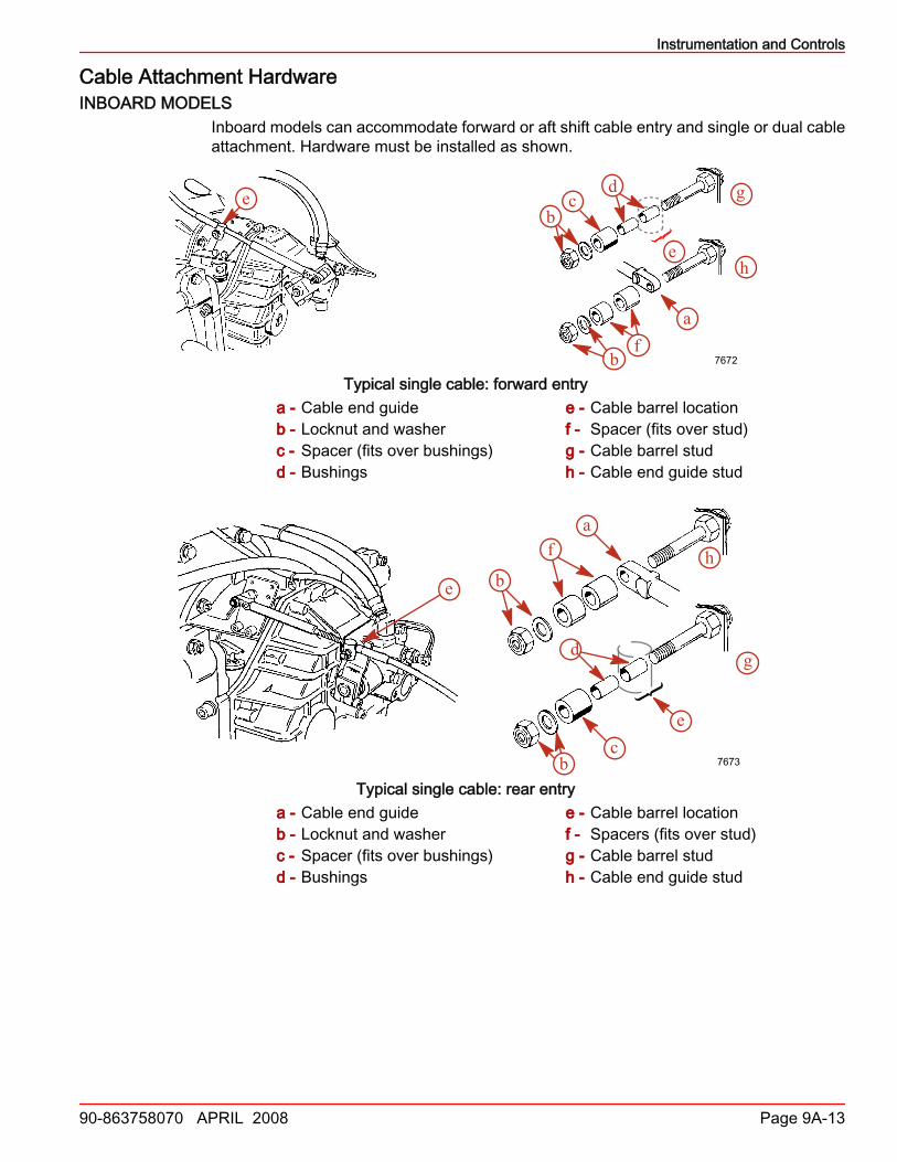
Inboard models can accommodate forward or aft shift cable entry and single or dual cableattachment. Hardware must be installed as shown.
e
a
b
cd
f
e
bg
h
7672
Typical single cable: forward entrya - Cable end guideb - Locknut and washerc - Spacer (fits over bushings)d - Bushings
e - Cable barrel locationf - Spacer (fits over stud)g - Cable barrel studh - Cable end guide stud
e
e
fa
b
bc
d g
h
7673
Typical single cable: rear entrya - Cable end guideb - Locknut and washerc - Spacer (fits over bushings)d - Bushings
e - Cable barrel locationf - Spacers (fits over stud)g - Cable barrel studh - Cable end guide stud

Instrumentation and Controls
Page 9A-14 90-863758070 APRIL 2008
e
e
b
b
a
c
d
g
f
7674
Typical dual cable: forward entrya - Cable end guidesb - Locknut and washerc - Spacer (fits over stud)d - Bushings
e - Cable barrel locationsf - Cable barrel studg - Cable end guide stud
e a
b
c
d
eb
f
g
7675
Typical dual cable: rear entrya - Cable end guidesb - Locknut and washerc - Spacer (fits over stud)d - Bushings
e - Cable barrel locationsf - Cable barrel studg - Cable end guide stud
Instrumentation and Controls
90-863758070 APRIL 2008 Page 9A-15
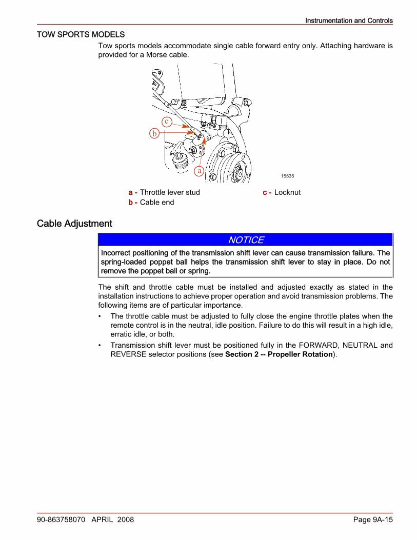
TOW SPORTS MODELSTow sports models accommodate single cable forward entry only. Attaching hardware isprovided for a Morse cable.
a
bc
15535
a - Throttle lever studb - Cable end
c - Locknut
Cable AdjustmentNOTICE
Incorrect positioning of the transmission shift lever can cause transmission failure. Thespring‑loaded poppet ball helps the transmission shift lever to stay in place. Do notremove the poppet ball or spring.
The shift and throttle cable must be installed and adjusted exactly as stated in theinstallation instructions to achieve proper operation and avoid transmission problems. Thefollowing items are of particular importance.• The throttle cable must be adjusted to fully close the engine throttle plates when the
remote control is in the neutral, idle position. Failure to do this will result in a high idle,erratic idle, or both.
• Transmission shift lever must be positioned fully in the FORWARD, NEUTRAL andREVERSE selector positions (see Section 2 -- Propeller Rotation).

Instrumentation and Controls
Page 9A-16 90-863758070 APRIL 2008
• On Velvet Drive models, the shift lever must be in the designated detent position foreach gear.
e
b
a
d
c
7665
Velvet Drive 5000 series (8 degree down angle shown, V‑drive similar)a - Transmission shift leverb - Poppet ball must be centered in
this detent hole when left‑handpropeller shaft rotation is desired
c - Poppet ball must be centered inthis detent hole when right‑handpropeller shaft rotation is desired
d - Poppet ball must be centered in thisdetent hole for neutral position
e - Install shift lever stud in this holewhen using quicksilver shift cables
• On ZF Marine (Hurth) transmissions, the shift lever must be against the stops forforward and reverse, and in the centered detent position for neutral.
8297
b
a
Typical ZF Marine (Hurth) transmission showna - Shift lever b - Shift cable bracket

Instrumentation and Controls
90-863758070 APRIL 2008 Page 9A-17
• Velvet Drive In‑line 71C and 72C transmissions must be operated with the shift leverin the FORWARD gear selector position when propelling the boat forward. Damage totransmission will result if it is operated in REVERSE (with the wrong rotation propeller)under full power.
F N R- -
F R
a
b
c
de
7653
Velvet Drive 71C and 72C Transmissiona - Transmission shift leverb - Shift lever must be over this letter
when propelling boat FORWARDc - Shift lever must be over this letter
when propelling boat in REVERSE
d - Poppet ball must be centered indetent hole for each F‑N‑R position(FORWARD gear shown)
e - Install shift lever stud in this hole, tocenter poppet ball in FORWARDand REVERSE detent holes
MotoviewerMotoViewer Service Tool
At this time, the Computer Diagnostic System (CDS) software does not communicate withproducts using the PCM 09 controller through the RS‑485 connection. However, all engineand vessel set up, information, and fault codes are available using a new software packagefrom MotoTron called MotoViewer. All communications to MotoViewer travel over theexisting RS‑485 connection using the CDS laptop and SmartComms. You must install aspecial SmartComms software update (CDS 8.2x) to the CDS laptop to use MotoTronsoftware. Contact your Product Integration Engineer (PIE) or Technical Account Manager(TAM) for assistance.To connect MotoViewer to an engine using PCM 09, obtain the following:
Description Part Number
SmartComms Interface Box
System contact:SPX Corporation28635 Mound Rd.Warren, MI 48092
or call:USA ‑ 1‑800‑345‑2233
Canada ‑ 800‑345‑2233Europe ‑ 49 6182 959 149Australia ‑ (03) 9544‑6222
Diagnostic Tester Harness Assembly for PCM 555 models 84‑822560A13
NOTE: If the Diagnostic Tester Harness Assembly (84‑822560A13) is unavailable, you canorder harness 84‑822560T12 and adapter 84‑822560A5.

Instrumentation and Controls
Page 9A-18 90-863758070 APRIL 2008
Saving Special FunctionsIMPORTANT: You must cycle the key switch after performing some special functions tostore the calibration values in the propulsion control module (PCM). If you are saving aspecial function on a DTS engine, you must also place the remote control in reverse, wideopen throttle (RWOT).Access special functions from the Special menu.
35003
Special functions that require a key cycle include:• Set Engine Location• Turn AutoSync Off• Alter Trim Limit• Alter Trailer Limit• Configure Easy‑Link GaugesTo save a special function calibration to the PCM:1. Perform the special function as described in this manual and the on‑screen prompts.2. Turn the key switch to "OFF" to retain settings.3. If the engine is equipped with DTS, turn the key switch to "OFF" and place the remote
control handle in reverse, wide‑open throttle (RWOT) to retain settings.NOTE: The Cylinder Misfire, Output Device Control, Start, and Emergency Stop! featuresare disabled.
Clearing Fault History1. From the Special menu, select Clear Fault History.
35006

Instrumentation and Controls
90-863758070 APRIL 2008 Page 9A-19
2. Click OK to clear the fault history or Cancel to abort.
35007
Setting Engine Location1. Turn the key switch to the "ON" position.2. From the Special menu, select Set Engine Location.
35008
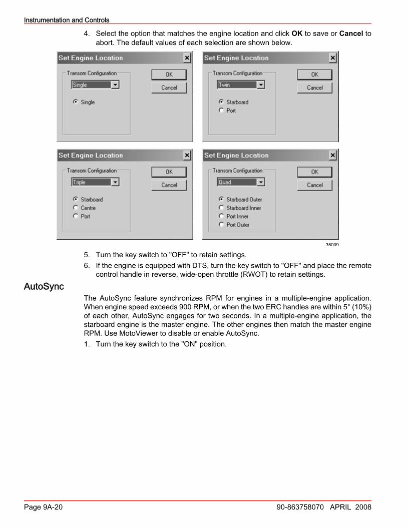
3. From the Transom Configuration drop‑down list, choose the configuration that matchesthe vessel: Single, Twin, Triple, or Quad.
Instrumentation and Controls
Page 9A-20 90-863758070 APRIL 2008
4. Select the option that matches the engine location and click OK to save or Cancel toabort. The default values of each selection are shown below.
35009
5. Turn the key switch to "OFF" to retain settings.6. If the engine is equipped with DTS, turn the key switch to "OFF" and place the remote
control handle in reverse, wide‑open throttle (RWOT) to retain settings.AutoSync
The AutoSync feature synchronizes RPM for engines in a multiple‑engine application.When engine speed exceeds 900 RPM, or when the two ERC handles are within 5° (10%)of each other, AutoSync engages for two seconds. In a multiple‑engine application, thestarboard engine is the master engine. The other engines then match the master engineRPM. Use MotoViewer to disable or enable AutoSync.1. Turn the key switch to the "ON" position.
Instrumentation and Controls
90-863758070 APRIL 2008 Page 9A-21
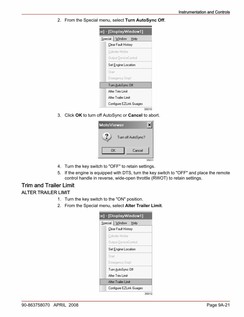
2. From the Special menu, select Turn AutoSync Off.
35010
3. Click OK to turn off AutoSync or Cancel to abort.
35011
4. Turn the key switch to "OFF" to retain settings.5. If the engine is equipped with DTS, turn the key switch to "OFF" and place the remote
control handle in reverse, wide‑open throttle (RWOT) to retain settings.Trim and Trailer LimitALTER TRAILER LIMIT
1. Turn the key switch to the "ON" position.2. From the Special menu, select Alter Trailer Limit.
35012
Instrumentation and Controls
Page 9A-22 90-863758070 APRIL 2008
3. Trim the drive down using the electronic remote control (ERC) until the drive reachesits full, down position and squeaks for 3 seconds. The PCM records this as the full,down position.
4. Trailer the drive up using the ERC or other switch to the highest position possiblewithout contacting the vessel or damaging components. The PCM records this locationas the upper trailer limit (100%).
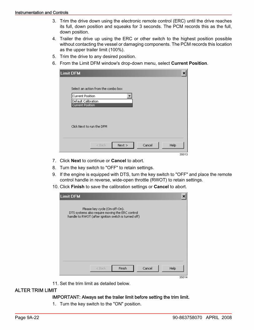
5. Trim the drive to any desired position.6. From the Limit DFM window's drop‑down menu, select Current Position.
35013
7. Click Next to continue or Cancel to abort.8. Turn the key switch to "OFF" to retain settings.9. If the engine is equipped with DTS, turn the key switch to "OFF" and place the remote
control handle in reverse, wide‑open throttle (RWOT) to retain settings.10. Click Finish to save the calibration settings or Cancel to abort.
35014
11. Set the trim limit as detailed below.ALTER TRIM LIMIT
IMPORTANT: Always set the trailer limit before setting the trim limit.1. Turn the key switch to the "ON" position.
Instrumentation and Controls
90-863758070 APRIL 2008 Page 9A-23
2. From the Special menu, select Alter Trim Limit.
35097
3. Trim the drive down using the electronic remote control (ERC), until the drive reachesits full, down position and squeaks for 3 seconds. The PCM records this as the full,down position.
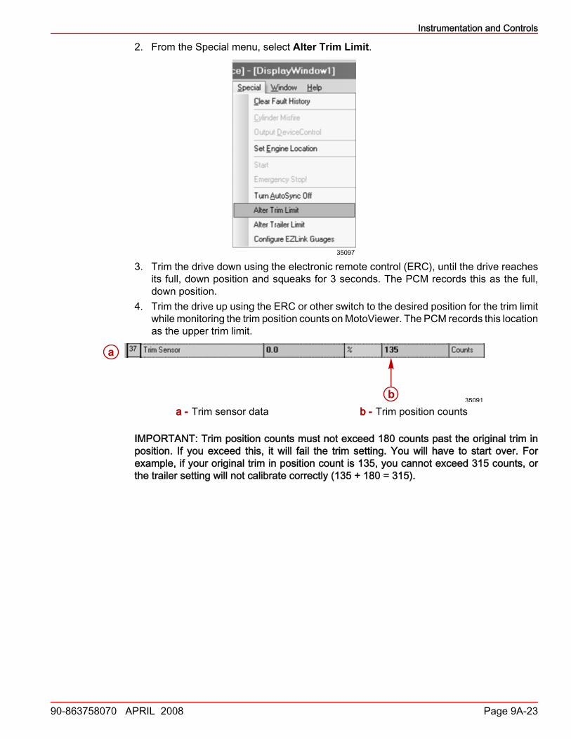
4. Trim the drive up using the ERC or other switch to the desired position for the trim limitwhile monitoring the trim position counts on MotoViewer. The PCM records this locationas the upper trim limit.
a
b35091
a - Trim sensor data b - Trim position counts
IMPORTANT: Trim position counts must not exceed 180 counts past the original trim inposition. If you exceed this, it will fail the trim setting. You will have to start over. Forexample, if your original trim in position count is 135, you cannot exceed 315 counts, orthe trailer setting will not calibrate correctly (135 + 180 = 315).
Instrumentation and Controls
Page 9A-24 90-863758070 APRIL 2008
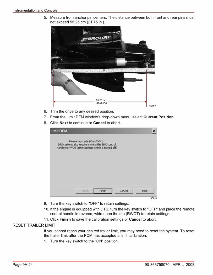
5. Measure from anchor pin centers. The distance between both front and rear pins mustnot exceed 55.25 cm (21.75 in.).
35087
55.25 cm(21.75 in.)
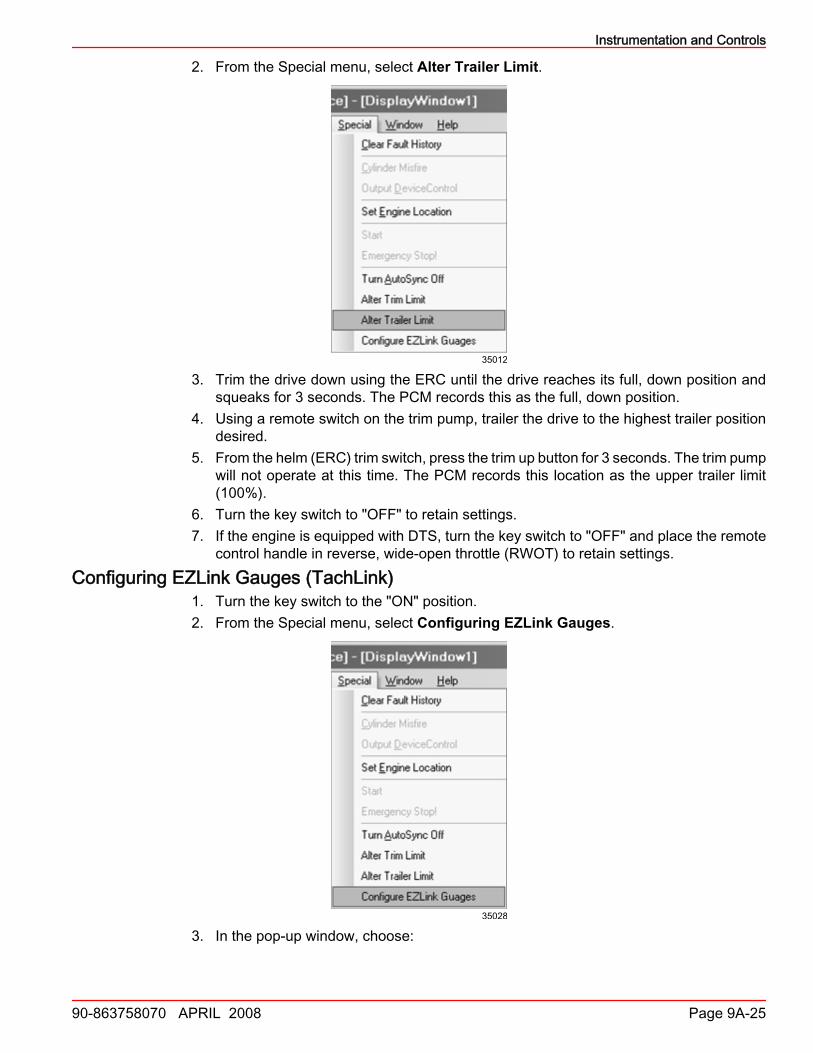
6. Trim the drive to any desired position.7. From the Limit DFM window's drop‑down menu, select Current Position.8. Click Next to continue or Cancel to abort.
35014
9. Turn the key switch to "OFF" to retain settings.10. If the engine is equipped with DTS, turn the key switch to "OFF" and place the remote
control handle in reverse, wide‑open throttle (RWOT) to retain settings.11. Click Finish to save the calibration settings or Cancel to abort.
RESET TRAILER LIMITIf you cannot reach your desired trailer limit, you may need to reset the system. To resetthe trailer limit after the PCM has accepted a limit calibration:1. Turn the key switch to the "ON" position.
Instrumentation and Controls
90-863758070 APRIL 2008 Page 9A-25
2. From the Special menu, select Alter Trailer Limit.
35012
3. Trim the drive down using the ERC until the drive reaches its full, down position andsqueaks for 3 seconds. The PCM records this as the full, down position.
4. Using a remote switch on the trim pump, trailer the drive to the highest trailer positiondesired.
5. From the helm (ERC) trim switch, press the trim up button for 3 seconds. The trim pumpwill not operate at this time. The PCM records this location as the upper trailer limit(100%).
6. Turn the key switch to "OFF" to retain settings.7. If the engine is equipped with DTS, turn the key switch to "OFF" and place the remote
control handle in reverse, wide‑open throttle (RWOT) to retain settings.Configuring EZLink Gauges (TachLink)
1. Turn the key switch to the "ON" position.2. From the Special menu, select Configuring EZLink Gauges.
35028
3. In the pop‑up window, choose:
Instrumentation and Controls
Page 9A-26 90-863758070 APRIL 2008
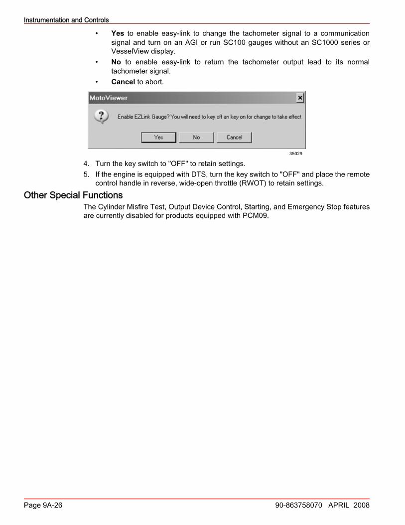
• Yes to enable easy‑link to change the tachometer signal to a communicationsignal and turn on an AGI or run SC100 gauges without an SC1000 series orVesselView display.
• No to enable easy‑link to return the tachometer output lead to its normaltachometer signal.
• Cancel to abort.
35029
4. Turn the key switch to "OFF" to retain settings.5. If the engine is equipped with DTS, turn the key switch to "OFF" and place the remote
control handle in reverse, wide‑open throttle (RWOT) to retain settings.Other Special Functions
The Cylinder Misfire Test, Output Device Control, Starting, and Emergency Stop featuresare currently disabled for products equipped with PCM09.