Embed Size (px)
Citation preview

InstrumentationQuick CouplingProducts
The World Standard
Catalog 4220/USAFebruary 2006
Parker Hannifin CorporationQuick Coupling Division8145 Lewis RoadMinneapolis, MN 55427www.parker.com/quickcouplings
Catalog 4220/USA - 10M 02/06/GRA/AP
Your complete source for quali-ty tube fittings, hose & hose fit-tings brass fittings & valves,quick-disconnect couplings, andassembly tools, locally-availablefrom a worldwide network of dis-tributors.
Fittings & Couplings:Available in inch and metric sizescovering SAE, BSP, DIN, GAZ,JIS and ISO thread configura-tions, manufactured from stain-less steel, brass, aluminum,nylon and thermoplastic.
Hose,Tubing and Bundles:Available in a wide variety ofsizes and materials includingrubber, wire-reinforced, thermo-plastic, hybrid and custom com-pounds.
Worldwide Availability:Parker operates Fluid Connectormanufacturing locations andsales offices throughout NorthAmerica, South America, Europeand Asia-Pacific.
Parker Hannifin CorporationQuick Coupling Division8145 Lewis RoadMinneapolis, MN 55427(763) 525-4240FAX (763) 544-3418
Parker Hannifin (Canada) Ltd.4635 Durham Road SouthPO Box 158Grimsby, Ontario L3M 4G4Canada(905) 945-2274FAX (905) 945-2203
Parker Hannifin Rak S.A.Quick Coupling Division17 rue des BuchillonsZI du Mont-Blanc - BP 524Ville-La-Grand74112 Annemasse, France(33) 450 878080FAX (33) 450 378685
Quick Coupling Division Sales Offices
FAILURE OR IMPROPER SELECTION OR IMPROPER USE OF THE PRODUCTS AND/OR SYSTEMS DESCRIBED HEREIN OR RELATED ITEMS CAN CAUSE DEATH, PERSONALINJURY AND PROPERTY DAMAGE.
This document and other information from Parker Hannifin Corporation, it's subsidiaries and authorized distributors provide product and/or system options for further investigation byusers having technical expertise. It is important that you analyze all aspects of your application and review the information concerning the product or system in the current product catalog.Due to the variety of operating conditions and applications for these products or systems, the user, through its own analysis and testing, is solely responsible for making the final selectionof the products and systems and assuring that all performance, safety and warning requirements of the application are met.
The products described herein, including without limitation, product features, specifications, designs, availability and pricing, are subject to change by Parker Hannifin Corporation and itssubsidiaries at any time without notice.
Offer of SaleThe items described in this document are hereby offered for sale by Parker Hannifin Corporation, its subsidiaries or its authorized distributors. This offer and its acceptance are governedby the provisions stated in the “Offer of Sale.”
Quick Coupling Division8145 Lewis Road
Minneapolis, MN 55427
© 2006, Revised January 2006, Parker Hannifin Corporation, All Rights Reserved.
Quick Coupling Products
Note: Flow charts in this catalog reflect actual test data. Flow tests were conducted using ANSI standard test procedures.
Introduction
The Parker Hannifin Quick Coupling Division offers a fullrange of precision quick action couplings for use in the pro-cess, power and instrumentation fields.
Quick couplings are used to quickly and easily connect anddisconnect rigid or flexible tubing to hose or pipe–without theuse of tools. They are available in straight-through (no valv-ing), single shut-off (valving in the coupler half only), and dou-ble shut-off (valving in both the coupler and nipple halves)configurations for maximum flexibility. With sealing integrity to1 x 10-6 cc/sec of helium at 50 millitor, Parker Quick Couplingsare ideal for use with a wide range of media in vacuum orhigh pressure applications.
Available end configurations include: Male and Female PipeThread, A-LOK® and CPI tube ends, 37° Flare, Hose Barb,and Bulkhead fittings. Stainless Steel couplings featureFluorocarbon seals as standard. Brass Couplings areequipped with Nitrile seals. Ethylene Propylene,Perfluoroelastomer, and other seal materials are also avail-able upon request.
Consult the Safety Guide in the back of this catalog for moreinformation on the selection and use of quick action cou-plings.
Parker Quick couplings designed for instrumentation applica-tions are built to stringent standards and meticulously testedfor sealing integrity. Applications for these precision couplingsinclude, but are not limited to the following:
• All types of instruments
• Laboratory equipment
• Vacuum systems
• Chemical research
• Gas supply systems
• Portable analyzers
• Control panels
• Hydraulic and pneumatic systems
• Medical equipment
• Food processing equipment
• Calibration systems
• Test stands
• Gas chromatographs
• Micro-contamination devices
Introduction
Parker Hannifin CorporationQuick Coupling Division
Minneapolis, MN 5542749
Quick Coupling ProductsOffer of Sale
The items described in this document are hereby offered for sale at prices to be established by Parker Hannifin Corporation, its subsidiaries and itsauthorized distributors.This offer and its acceptance by any customer (“Buyer”) shall be governed by all of the following Terms and Conditions. Buyer’sorder for any item described in its document, when communicated to Parker Hannifin Corporation, its subsidiary or an authorized distributor (“Seller”)verbally or in writing, shall constitute acceptance of this offer.
1. Terms and Conditions of Sale: All descriptions, quotations, proposals, offers,acknowledgments, acceptances and sales of Seller’s products are subject to andshall be governed exclusively by the terms and conditions stated herein. Buyer’sacceptance of any offer to sell is limited to these terms and conditions. Any terms orconditions in addition to, or inconsistent with those stated herein, proposed byBuyer in any acceptance of an offer by Seller, are hereby objected to. No such addi-tional, different or inconsistent terms and conditions shall become part of the con-tract between Buyer and Seller unless expressly accepted in writing by Seller.Seller’s acceptance of any offer to purchase by Buyer is expressly conditional uponBuyer’s assent to all the terms and conditions stated herein, including any terms inaddition to, or inconsistent with those contained in Buyer’s offer. Acceptance ofSeller’s products shall in all events constitute such assent.
2. Payment: Payment shall be made by Buyer net 30 days from the date of deliv-ery of the items purchased hereunder. Amounts not timely paid shall bear interestof 1% for each month or a portion thereof that Buyer is late in making payment.Any claims by Buyer for omissions or shortages in a shipment shall be waivedunless Seller receives notice thereof within 30 days after Buyer’s receipt of the ship-ment.
3. Delivery: Unless otherwise provided on the face hereof, delivery shall be madeF.O.B. Seller’s plant. Regardless of the method of delivery, however, risk of lossshall pass to Buyer upon Seller’s delivery to a carrier. Any delivery dates shown areapproximate only and Seller shall have no liability for any delays in delivery.
4. Warranty: Seller warrants that the items sold hereunder shall be free fromdefects in material or workmanship for a period of 365 days from the date of ship-ment to Buyer. THIS WARRANTY COMPRISES THE SOLE AND ENTIRE WAR-RANTY PERTAINING TO ITEMS PROVIDED HEREUNDER. SELLER MAKESNO OTHER WARRANTY, GUARANTEE, OR REPRESENTATION OF ANY KINDWHATSOEVER. ALL OTHER WARRANTIES, INCLUDING BUT NOT LIMITEDTO, MERCHANTIBILITY AND FITNESS FOR PURPOSE,WHETHER EXPRESS,IMPLIED, OR ARISING BY OPERATION OF LAW,TRADE USAGE, OR COURSEOF DEALING ARE HEREBY DISCLAIMED.
NOTWITHSTANDING THE FOREGOING,THERE ARE NO WARRANTIES WHAT-SOEVER ON ITEMS BUILT OR ACQUIRED WHOLLY OR PARTIALLY,TOBUYER’S DESIGNS OR SPECIFICATIONS.
5. Limitation Of Remedy: SELLER’S LIABILITY ARISING FROM OR IN ANYWAY CONNECTED WITH THE ITEMS SOLD OR THIS CONTRACT SHALL BELIMITED EXCLUSIVELY TO REPAIR OR REPLACEMENT OF THE ITEMSSOLD OR REFUND OF THE PURCHASE PRICE PAID BY BUYER, AT SELL-ER’S SOLE OPTION. IN NO EVENT SHALL SELLER BE LIABLE FOR ANYINCIDENTAL, CONSEQUENTIAL OR SPECIAL DAMAGES OF ANY KIND ORNATURE WHATSOEVER, INCLUDING BUT NOT LIMITED TO LOST PROFITSARISING FROM OR IN ANY WAY CONNECTED WITH THIS AGREEMENT ORITEMS SOLD HEREUNDER,WHETHER ALLEDGED TO ARISE FROM BREACHOF CONTRACT, EXPRESS OR IMPLIED WARRANTY, OR IN TORT, INCLUDINGWITHOUT LIMITATION, NEGLIGENCE, FAILURE TO WARN OR STRICT LIABIL-ITY.
6. Changes, Reschedules and Cancellations: Buyer may request to modify thedesigns or specifications for the items sold hereunder as well as the quantities anddelivery dates thereof, or may request to cancel all or part of this order, however, nosuch requested modification or cancellation shall become part of the contractbetween Buyer and Seller unless accepted by Seller in a written amendment to thisAgreement. Acceptance of any such requested modification or cancellation shall beat Seller’s discretion, and shall be upon such terms and conditions as Seller mayrequire.
7. Special Tooling: A tooling charge may be imposed for any special tooling,including without limitation, dies, fixtures, molds and patterns, acquired to manufac-ture items sold pursuant to this contract. Such special tooling shall be and remainSeller’s property notwithstanding payment of any charges therefore by Buyer. In noevent will Buyer acquire any interest in apparatus belonging to Seller which is uti-lized in the manufacture of the items sold hereunder, even if such apparatus hasbeen specially converted or adapted for such manufacture and notwithstanding anycharges paid by Buyer therefore. Unless otherwise agreed, Seller shall have theright to alter, discard or otherwise dispose of any special tooling or other property inits sole discretion at any time.
8. Buyer’s Property: Any designs, tools, patterns, materials, drawings, confiden-tial information or equipment furnished by the Buyer or any other items whichbecome Buyer’s property, may be considered obsolete and may be destroyed bySeller after two (2) consecutive years have elapsed without Buyer placing an orderfor the items which are manufactured using such property. Seller shall not beresponsible for any loss or damage to such property while it is in Seller’s posses-sion or control.
9. Taxes: Unless otherwise indicated on the face hereof, all prices and charges areexclusive of excise, sales, use, property, occupational or like taxes which may beimposed by any taxing authority upon the manufacture, sale or delivery of the itemssold hereunder. If any such taxes must be paid by Seller or if Seller is liable for thecollection of such tax, the amount thereof shall be in addition to the amounts for theitems sold. Buyer agrees to pay all such taxes or to reimburse Seller therefore uponreceipt of its invoice. If Buyer claims exemption from any sales, use or other taximposed by any taxing authority, Buyer shall save Seller harmless from and againstany such tax, together with any interest or penalties thereon which may beassessed if the items are held to be taxable.
10. Indemnity For Infringement of Intellectual Property Rights: Seller shallhave no liability for infringement of any patents, trademarks, copyrights, tradedress, trade secrets or similar rights except as provided in this Part 10. Seller willdefend and indemnify Buyer against allegations of infringement of U.S. patents.U.S. trademarks, copyrights, trade dress and trade secrets (hereinafter ‘IntellectualProperty Rights’). Seller will defend at its expense and will pay the cost of any set-tlement or damages awarded in an action brought against Buyer based on an alle-gation that an item sold pursuant to this contract infringes the Intellectual PropertyRights of a third party. Seller’s obligation to defend and indemnify Buyer is contin-gent on Buyer notifying Seller within ten (10) days after Buyer becomes aware ofsuch allegations of infringement, and Seller having sole control over the defense ofany allegations or actions including all negotiations for settlement or compromise. Ifan item sold hereunder is subject to a claim that it infringes the Intellectual PropertyRights of a third party, Seller may, at its sole expense and option, procure for Buyerthe right to continue using said item, replace or modify said item so as to make itnoninfringing, or offer to accept return of said item and return the purchase priceless a reasonable allowance for depreciation. Notwithstanding the foregoing, Sellershall have no liability for claims of infringement based on information provided byBuyer, or directed to items delivered hereunder for which the designs are specifiedin whole or part by Buyer, or infringements resulting from the modification, combi-nation or use in a system of any item sold hereunder. The foregoing provisions ofthis Part 10 shall constitute Seller’s sole and exclusive liability and Buyer’s sole andexclusive remedy for infringement of Intellectual Property rights.
If a claim is based on information provided by Buyer or if the design for an itemdelivered hereunder is specified in whole or in part by Buyer, Buyer shall defendand indemnify Seller for all costs, expenses or judgments resulting from any claimthat such item infringes any patent, trademark, copyright, trade dress, trade secretor any similar right.
11. Force Majeure: Seller does not assume the risk of and shall not be liable fordelay or failure to perform any of Seller’s obligations by reason of circumstancesbeyond the reasonable control of Seller (hereinafter ‘Events of Force Majeure’).Events of Force Majeure shall include without limitation, accidents, acts of God,strikes or labor disputes, acts, laws, rules or regulations of any government or gov-ernment agency, fires, floods, delays or failures in delivery of carriers or suppliers,shortages of materials and any other cause beyond Seller’s control.
12. Entire Agreement/Governing Law: The terms and conditions set forth herein,together with any amendments, modifications and any different terms or conditionsexpressly accepted by Seller in writing, shall constitute the entire Agreement con-cerning the items sold, and there are no oral or other representations or agree-ments which pertain thereto. This Agreement shall be governed in all respects bythe law of the State of Ohio. No actions arising out of the sale of the items soldhereunder or this Agreement may be brought by either party more than two (2)years after the cause of action accrues.
Parker Hannifin CorporationQuick Coupling Division
Minneapolis, MN 554271
Quick Coupling Products
Table Of Contents .......................................................1
Fluid Quick Couplings................................................3Coupling Selection Guide ........................................4
Non-Spill Couplings..................................................5FS Series ..................................................................5
Couplers ................................................................6Nipples...................................................................7
FS Series Dust Caps & Plugs ...................................8FS Series Repair Kits................................................8
CPI Series...............................................................9Couplers ................................................................10Nipples: Valved ......................................................11Nipples: Non Valved...............................................12CPI Series Coupler and Nipple Protectors............13Ordering Information .............................................13
High Flow Couplings .............................................14ST Series ................................................................14Couplers ................................................................15Nipples...................................................................16
General Purpose Couplings ..................................1760 Series.................................................................17Couplers and Nipples 1/8” – 1”..............................19Couplers and Nipples 1 1/2” – 2 1/2”.....................20
60 Series Dust Caps & Plugs..................................19Optional Seals.........................................................2060 Series Repair Kits ..............................................20
Thermoplastic Quick Couplings .............................21Coupling Selection Guide ....................................22
PF Series..................................................................23Couplers ................................................................24Nipples...................................................................24
PF Series Dust Caps & Plugs .................................24
Spectrum Series......................................................25Couplers ................................................................26Nipples: Valved ......................................................27Nipples: Non Valved...............................................28
Pneumatic Quick Couplings....................................29Coupling Selection Guide ......................................30
Pneumatic Couplings .............................................31HF Series................................................................31Couplers ...............................................................32Nipples ..................................................................32
Industrial Interchange Nipples.............................35DM Series...............................................................37Couplers ................................................................38Nipples...................................................................38
Appendices................................................................39
Fluid Compatibility Chart .........................................40
Glossary Of Terms ....................................................46
Safety Guide ..............................................................47
Offer Of Sale ..............................................................49
Table of Contents
Parker Hannifin CorporationQuick Coupling Division
Minneapolis, MN 554273
Quick Coupling Products
FluidQuick
Couplings
Parker Hannifin CorporationQuick Coupling Division
Minneapolis, MN 554274
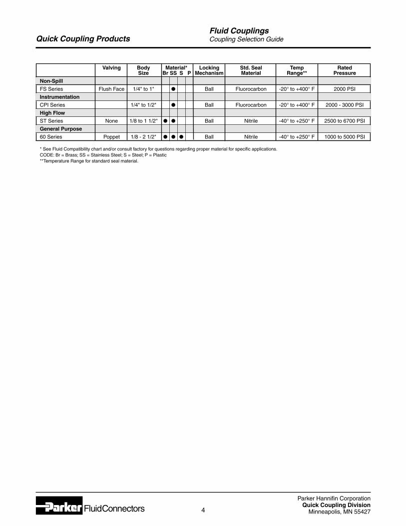
Quick Coupling ProductsFluid CouplingsCoupling Selection Guide
Valving Body Material* Locking Std. Seal Temp RatedSize Br SS S P Mechanism Material Range** Pressure
Non-Spill
FS Series Flush Face 1/4" to 1" l Ball Fluorocarbon -20° to +400° F 2000 PSI
Instrumentation
CPI Series 1/4" to 1/2" l Ball Fluorocarbon -20° to +400° F 2000 - 3000 PSI
High Flow
ST Series None 1/8 to 1 1/2" l l Ball Nitrile -40° to +250° F 2500 to 6700 PSI
General Purpose
60 Series Poppet 1/8 - 2 1/2" l l l Ball Nitrile -40° to +250° F 1000 to 5000 PSI
* See Fluid Compatibility chart and/or consult factory for questions regarding proper material for specific applications.CODE: Br = Brass; SS = Stainless Steel; S = Steel; P = Plastic**Temperature Range for standard seal material.
Parker Hannifin CorporationQuick Coupling Division
Minneapolis, MN 554275
Quick Coupling Products
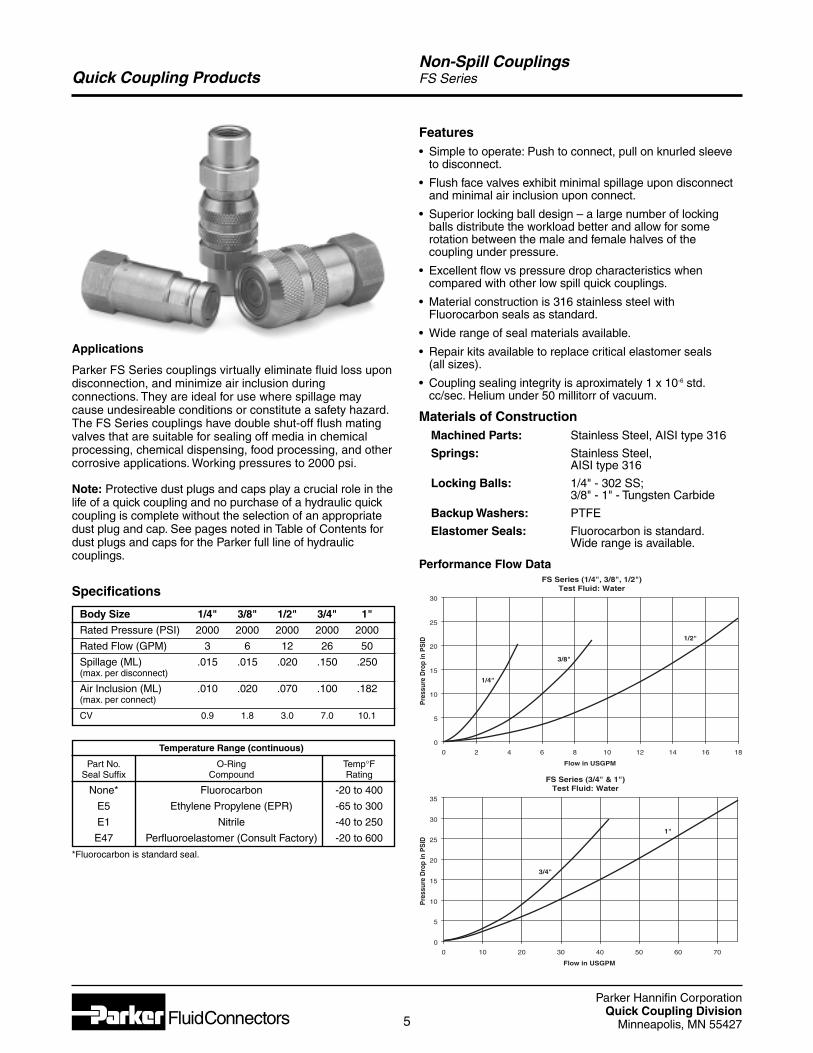
Note: Protective dust plugs and caps play a crucial role in thelife of a quick coupling and no purchase of a hydraulic quickcoupling is complete without the selection of an appropriatedust plug and cap. See pages noted in Table of Contents fordust plugs and caps for the Parker full line of hydrauliccouplings.
Applications
Parker FS Series couplings virtually eliminate fluid loss upondisconnection, and minimize air inclusion duringconnections. They are ideal for use where spillage maycause undesireable conditions or constitute a safety hazard.The FS Series couplings have double shut-off flush matingvalves that are suitable for sealing off media in chemicalprocessing, chemical dispensing, food processing, and othercorrosive applications. Working pressures to 2000 psi.
Features• Simple to operate: Push to connect, pull on knurled sleeve
to disconnect.
• Flush face valves exhibit minimal spillage upon disconnectand minimal air inclusion upon connect.
• Superior locking ball design – a large number of lockingballs distribute the workload better and allow for somerotation between the male and female halves of thecoupling under pressure.
• Excellent flow vs pressure drop characteristics whencompared with other low spill quick couplings.
• Material construction is 316 stainless steel withFluorocarbon seals as standard.
• Wide range of seal materials available.
• Repair kits available to replace critical elastomer seals (all sizes).
• Coupling sealing integrity is aproximately 1 x 10⁻⁶ std.cc/sec. Helium under 50 millitorr of vacuum.
Materials of ConstructionMachined Parts: Stainless Steel, AISI type 316
Springs: Stainless Steel,AISI type 316
Locking Balls: 1/4" - 302 SS;3/8" - 1" - Tungsten Carbide
Backup Washers: PTFE
Elastomer Seals: Fluorocarbon is standard.Wide range is available.
Performance Flow DataFS Series (1/4", 3/8", 1/2")
Test Fluid: Water
0
5
10
15
20
25
30
0 2 4 6 8 10 12 14 16 18
Flow in USGPM
Pre
ssur
e D
rop
inP
SID
1/4"
3/8"
1/2"
Specifications
Body Size 1/4" 3/8" 1/2" 3/4" 1"
Rated Pressure (PSI) 2000 2000 2000 2000 2000
Rated Flow (GPM) 3 6 12 26 50
Spillage (ML) .015 .015 .020 .150 .250(max. per disconnect)
Air Inclusion (ML) .010 .020 .070 .100 .182(max. per connect)
CV 0.9 1.8 3.0 7.0 10.1
Temperature Range (continuous)
Part No. O-Ring Temp°FSeal Suffix Compound Rating
None* Fluorocarbon -20 to 400
E5 Ethylene Propylene (EPR) -65 to 300
E1 Nitrile -40 to 250
E47 Perfluoroelastomer (Consult Factory) -20 to 600
*Fluorocarbon is standard seal.
Non-Spill CouplingsFS Series
FS Series (3/4" & 1")Test Fluid: Water
0
5
10
15
20
25
30
35
0 10 20 30 40 50 60 70
Flow in USGPM
Pre
ssur
e D
rop
inP
SID
3/4"
1"
Parker Hannifin CorporationQuick Coupling Division
Minneapolis, MN 554276
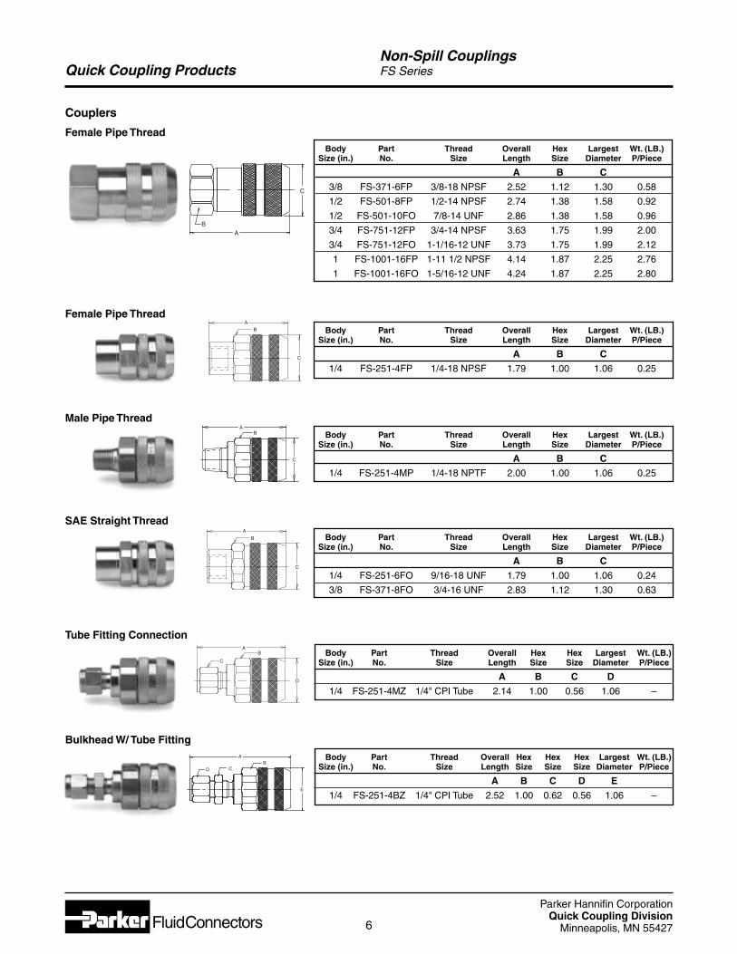
Quick Coupling ProductsNon-Spill CouplingsFS Series
Couplers
Female Pipe ThreadBody Part Thread Overall Hex Largest Wt. (LB.)
Size (in.) No. Size Length Size Diameter P/Piece
A B C
3/8 FS-371-6FP 3/8-18 NPSF 2.52 1.12 1.30 0.58
1/2 FS-501-8FP 1/2-14 NPSF 2.74 1.38 1.58 0.92
1/2 FS-501-10FO 7/8-14 UNF 2.86 1.38 1.58 0.96
3/4 FS-751-12FP 3/4-14 NPSF 3.63 1.75 1.99 2.00
3/4 FS-751-12FO 1-1/16-12 UNF 3.73 1.75 1.99 2.12
1 FS-1001-16FP 1-11 1/2 NPSF 4.14 1.87 2.25 2.76
1 FS-1001-16FO 1-5/16-12 UNF 4.24 1.87 2.25 2.80
Body Part Thread Overall Hex Largest Wt. (LB.)Size (in.) No. Size Length Size Diameter P/Piece
A B C
1/4 FS-251-4FP 1/4-18 NPSF 1.79 1.00 1.06 0.25
Female Pipe Thread
Body Part Thread Overall Hex Largest Wt. (LB.)Size (in.) No. Size Length Size Diameter P/Piece
A B C
1/4 FS-251-4MP 1/4-18 NPTF 2.00 1.00 1.06 0.25
Male Pipe Thread
Body Part Thread Overall Hex Largest Wt. (LB.)Size (in.) No. Size Length Size Diameter P/Piece
A B C
1/4 FS-251-6FO 9/16-18 UNF 1.79 1.00 1.06 0.24
3/8 FS-371-8FO 3/4-16 UNF 2.83 1.12 1.30 0.63
SAE Straight Thread
Body Part Thread Overall Hex Hex Largest Wt. (LB.)Size (in.) No. Size Length Size Size Diameter P/Piece
A B C D
1/4 FS-251-4MZ 1/4" CPI Tube 2.14 1.00 0.56 1.06 –
Tube Fitting Connection
Body Part Thread Overall Hex Hex Hex Largest Wt. (LB.)Size (in.) No. Size Length Size Size Size Diameter P/Piece
A B C D E
1/4 FS-251-4BZ 1/4" CPI Tube 2.52 1.00 0.62 0.56 1.06 –
Bulkhead W/ Tube FittingA
BCD
E
AB
C
BA
C
D
AB
C
A
B
C
AB
C
Parker Hannifin CorporationQuick Coupling Division
Minneapolis, MN 554277
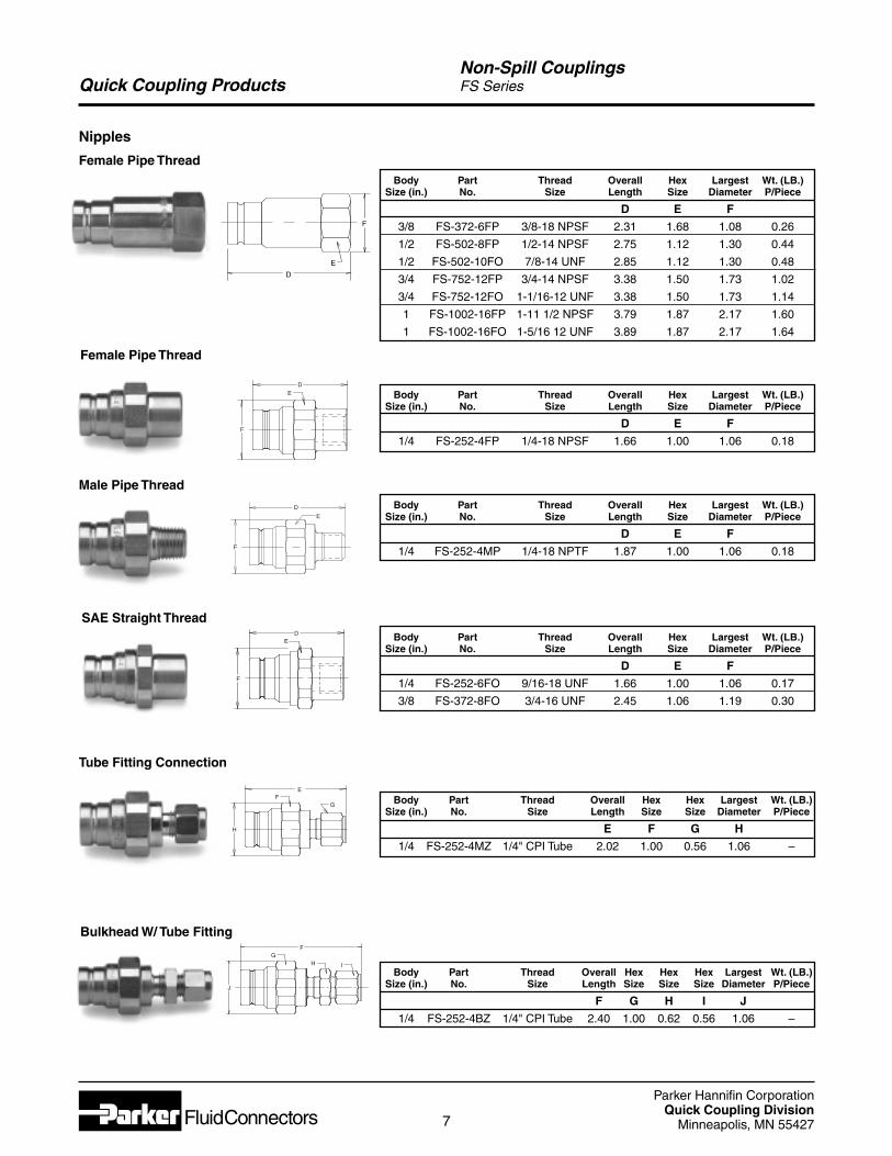
Quick Coupling ProductsNon-Spill CouplingsFS Series
Nipples
Female Pipe ThreadBody Part Thread Overall Hex Largest Wt. (LB.)
Size (in.) No. Size Length Size Diameter P/Piece
D E F
3/8 FS-372-6FP 3/8-18 NPSF 2.31 1.68 1.08 0.26
1/2 FS-502-8FP 1/2-14 NPSF 2.75 1.12 1.30 0.44
1/2 FS-502-10FO 7/8-14 UNF 2.85 1.12 1.30 0.48
3/4 FS-752-12FP 3/4-14 NPSF 3.38 1.50 1.73 1.02
3/4 FS-752-12FO 1-1/16-12 UNF 3.38 1.50 1.73 1.14
1 FS-1002-16FP 1-11 1/2 NPSF 3.79 1.87 2.17 1.60
1 FS-1002-16FO 1-5/16 12 UNF 3.89 1.87 2.17 1.64
Body Part Thread Overall Hex Largest Wt. (LB.)Size (in.) No. Size Length Size Diameter P/Piece
D E F
1/4 FS-252-4FP 1/4-18 NPSF 1.66 1.00 1.06 0.18
Body Part Thread Overall Hex Largest Wt. (LB.)Size (in.) No. Size Length Size Diameter P/Piece
D E F
1/4 FS-252-4MP 1/4-18 NPTF 1.87 1.00 1.06 0.18
Body Part Thread Overall Hex Largest Wt. (LB.)Size (in.) No. Size Length Size Diameter P/Piece
D E F
1/4 FS-252-6FO 9/16-18 UNF 1.66 1.00 1.06 0.17
3/8 FS-372-8FO 3/4-16 UNF 2.45 1.06 1.19 0.30
Male Pipe Thread
SAE Straight Thread
Tube Fitting Connection
Bulkhead W/ Tube Fitting
Body Part Thread Overall Hex Hex Largest Wt. (LB.)Size (in.) No. Size Length Size Size Diameter P/Piece
E F G H
1/4 FS-252-4MZ 1/4" CPI Tube 2.02 1.00 0.56 1.06 –
Body Part Thread Overall Hex Hex Hex Largest Wt. (LB.)Size (in.) No. Size Length Size Size Size Diameter P/Piece
F G H I J
1/4 FS-252-4BZ 1/4" CPI Tube 2.40 1.00 0.62 0.56 1.06 –
Female Pipe Thread
J
GH
F
I
ED
F
E
D
F
E
D
F
H
EF
G
D
E
F
Parker Hannifin CorporationQuick Coupling Division
Minneapolis, MN 554278
Quick Coupling ProductsNon-Spill CouplingsFS Series
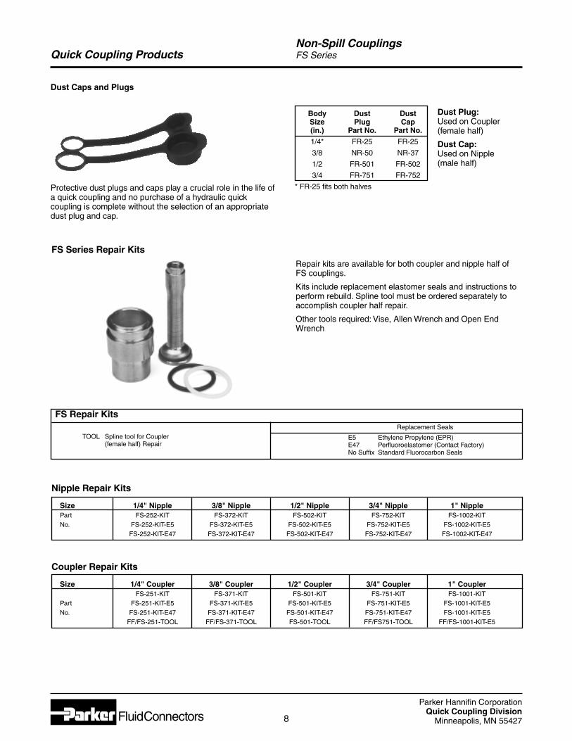
Dust Caps and Plugs
Body Dust DustSize Plug Cap(in.) Part No. Part No.
1/4* FR-25 FR-25
3/8 NR-50 NR-37
1/2 FR-501 FR-502
3/4 FR-751 FR-752
* FR-25 fits both halves
Dust Plug:Used on Coupler(female half)
Dust Cap:Used on Nipple(male half)
Protective dust plugs and caps play a crucial role in the life ofa quick coupling and no purchase of a hydraulic quickcoupling is complete without the selection of an appropriatedust plug and cap.
Nipple Repair Kits
Size 1/4" Nipple 3/8" Nipple 1/2" Nipple 3/4" Nipple 1" NipplePart FS-252-KIT FS-372-KIT FS-502-KIT FS-752-KIT FS-1002-KITNo. FS-252-KIT-E5 FS-372-KIT-E5 FS-502-KIT-E5 FS-752-KIT-E5 FS-1002-KIT-E5
FS-252-KIT-E47 FS-372-KIT-E47 FS-502-KIT-E47 FS-752-KIT-E47 FS-1002-KIT-E47
FS Series Repair Kits
Coupler Repair Kits
Size 1/4" Coupler 3/8" Coupler 1/2" Coupler 3/4" Coupler 1" CouplerFS-251-KIT FS-371-KIT FS-501-KIT FS-751-KIT FS-1001-KIT
Part FS-251-KIT-E5 FS-371-KIT-E5 FS-501-KIT-E5 FS-751-KIT-E5 FS-1001-KIT-E5No. FS-251-KIT-E47 FS-371-KIT-E47 FS-501-KIT-E47 FS-751-KIT-E47 FS-1001-KIT-E5
FF/FS-251-TOOL FF/FS-371-TOOL FS-501-TOOL FF/FS751-TOOL FF/FS-1001-KIT-E5
TOOL Spline tool for Coupler(female half) Repair
Replacement Seals
E5 Ethylene Propylene (EPR)E47 Perfluoroelastomer (Contact Factory)No Suffix Standard Fluorocarbon Seals
FS Repair Kits
Repair kits are available for both coupler and nipple half ofFS couplings.
Kits include replacement elastomer seals and instructions toperform rebuild. Spline tool must be ordered separately toaccomplish coupler half repair.
Other tools required: Vise, Allen Wrench and Open EndWrench
Parker Hannifin CorporationQuick Coupling Division
Minneapolis, MN 554279
Quick Coupling Products
Rated Working Pressure (PSI)
Body Size 1/4" 3/8" 1/2"
Connected 3000 1500 750
Disconnected 3000 1500 750
Connect Under Pressure* 250 250 250
*See Glossary of Terms
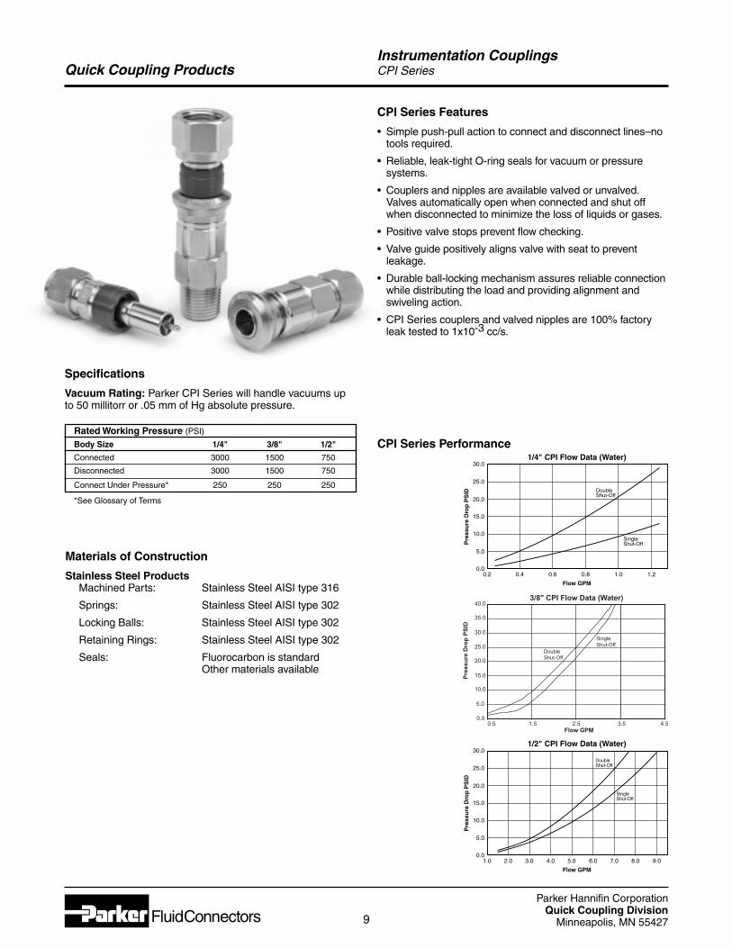
Specifications
Vacuum Rating: Parker CPI Series will handle vacuums upto 50 millitorr or .05 mm of Hg absolute pressure.
CPI Series Features
• Simple push-pull action to connect and disconnect lines–notools required.
• Reliable, leak-tight O-ring seals for vacuum or pressuresystems.
• Couplers and nipples are available valved or unvalved.Valves automatically open when connected and shut offwhen disconnected to minimize the loss of liquids or gases.
• Positive valve stops prevent flow checking.
• Valve guide positively aligns valve with seat to preventleakage.
• Durable ball-locking mechanism assures reliable connectionwhile distributing the load and providing alignment andswiveling action.
• CPI Series couplers and valved nipples are 100% factoryleak tested to 1x10⁻³ cc/s.
Materials of Construction
Stainless Steel ProductsMachined Parts: Stainless Steel AISI type 316
Springs: Stainless Steel AISI type 302
Locking Balls: Stainless Steel AISI type 302
Retaining Rings: Stainless Steel AISI type 302
Seals: Fluorocarbon is standardOther materials available
CPI Series Performance
Instrumentation CouplingsCPI Series
1/4" CPI Flow Data (Water)
Flow GPM
Pre
ssu
re D
rop
PS
ID30.0
25.0
20.0
15.0
10.0
5.0
0.00.2 0.4 0.6 0.8 1.0 1.2
Double Shut-Off
Single Shut-Off
Flow GPM
Pres
sure
Dro
p PS
ID
Double Shut-Off
SingleShut-Off
40.0
35.0
30.0
25.0
20.0
15.0
10.0
5.0
0.00.5 1.5 2.5 3.5 4.5
3/8" CPI Flow Data (Water)
1/2" CPI Flow Data (Water)
Flow GPM
Pre
ssu
re D
rop
PS
ID
30.0
25.0
20.0
15.0
10.0
5.0
0.01.0 3.02.0 4.0 6.0 8.05.0 7.0 9.0
Double Shut-Off
Single Shut-Off
Parker Hannifin CorporationQuick Coupling Division
Minneapolis, MN 5542710
Quick Coupling Products
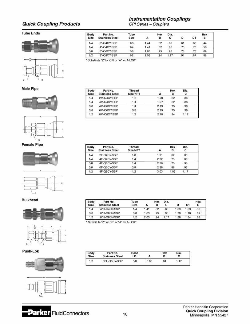
Body Part No. Tube Hex Dia. HexSize Stainless Steel Size A B C D D1 E
1/4 2*-Q4CY-SSP 1/8 1.44 .62 .86 .61 .60 .441/4 4*-Q4CY-SSP 1/4 1.41 .62 .86 .70 .70 .563/8 6*-Q6CY-SSP 3/8 1.63 .75 .98 .78 .76 .691/2 8*-Q8CY-SSP 1/2 2.03 .94 1.17 .91 .87 .88
* Substitute “Z” for CPI or “A” for A-LOK®
Body Part No. Thread Hex Dia.Size Stainless Steel Size/NPT A B C1/4 2M-Q4CY-SSP 1/8 1.78 .62 .861/4 4M-Q4CY-SSP 1/4 1.97 .62 .863/8 4M-Q6CY-SSP 1/4 2.19 .75 .983/8 6M-Q6CY-SSP 3/8 2.19 .75 .981/2 8M-Q8CY-SSP 1/2 2.78 .94 1.17
Tube Ends
Body Part No. Hose Hex Dia.Size Stainless Steel I.D. A B C
1/2 6PL-Q8CY-SSP 3/8 3.00 .94 1.17
Body Part No. Tube Hex Dia. HexSize Stainless Steel Size A B C D D1 E1/4 4*H-Q4CY-SSP 1/4 1.41 .62 .86 1.09 1.09 .563/8 6*H-Q6CY-SSP 3/8 1.63 .75 .98 1.20 1.18 .691/2 8*H-Q8CY-SSP 1/2 2.03 .94 1.17 1.38 1.34 .88
* Substitute “Z” for CPI or “A” for A-LOK®
Bulkhead
C
A
BE
DD1
Female Pipe
B
C
A
Male Pipe
B
C
A
C
A
BE
DD1
Body Part No. Thread Hex Dia.Size Stainless Steel Size/NPT A B C
1/4 2F-Q4CY-SSP 1/8 1.91 .62 .861/4 4F-Q4CY-SSP 1/4 2.22 .75 .863/8 4F-Q6CY-SSP 1/4 2.36 .75 .983/8 6F-Q6CY-SSP 3/8 2.38 .88 .981/2 8F-Q8CY-SSP 1/2 3.03 1.06 1.17
Push-Lok
B
A
C
Instrumentation CouplingsCPI Series – Couplers
Parker Hannifin CorporationQuick Coupling Division
Minneapolis, MN 5542711
Quick Coupling Products
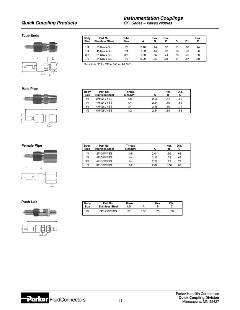
Body Part No. Tube Hex Dia. HexSize Stainless Steel Size A B C D D1 E
1/4 2*-Q4VY-SS 1/8 2.10 .44 .62 .61 .60 .441/4 4*-Q4VY-SS 1/4 1.53 .44 .62 .70 .70 .563/8 6*-Q6VY-SS 3/8 1.59 .56 .74 .78 .76 .691/2 8*-Q8VY-SS 1/2 2.09 .75 .88 .91 .87 .88
* Substitute “Z” for CPI or “A” for A-LOK®
Body Part No. Thread Hex Dia.Size Stainless Steel Size/NPT A B C1/4 2M-Q4VY-SS 1/8 2.58 .44 .621/4 4M-Q4VY-SS 1/4 2.24 .56 .623/8 4M-Q6VY-SS 1/4 2.15 .56 .741/2 8M-Q8VY-SS 1/2 2.84 .88 .88
Body Part No. Hose Hex Dia.Size Stainless Steel I.D. A B C
1/2 6PL-Q8VY-SS 3/8 3.56 .75 .88
Body Part No. Thread Hex Dia.Size Stainless Steel Size/NPT A B C
1/4 2F-Q4VY-SS 1/8 2.04 .56 .621/4 4F-Q4VY-SS 1/4 2.25 .75 .623/8 4F-Q6VY-SS 1/4 2.28 .75 .741/2 8F-Q8VY-SS 1/2 2.87 1.06 .88
Tube Ends
Female Pipe
Male Pipe
C
A
B E
D D1
C
B
A
C
B
A
Push-Lok
B
A
C
Instrumentation CouplingsCPI Series – Valved Nipples
Parker Hannifin CorporationQuick Coupling Division
Minneapolis, MN 5542712
Quick Coupling Products
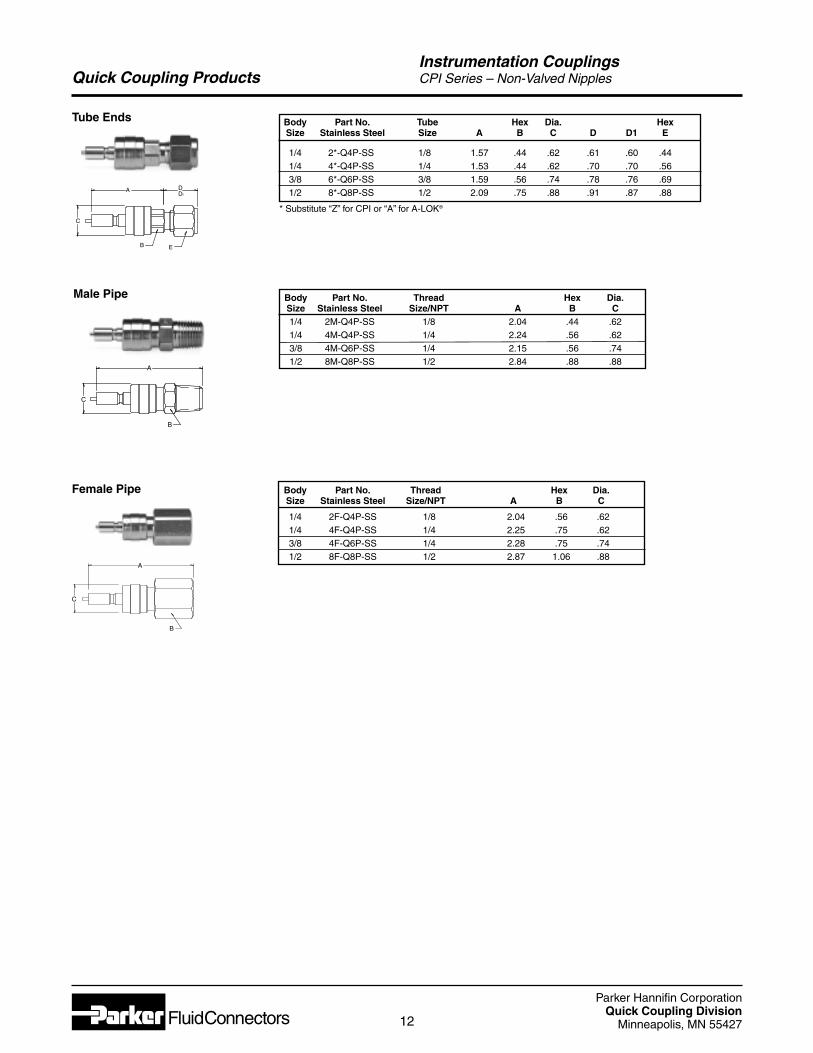
Body Part No. Tube Hex Dia. HexSize Stainless Steel Size A B C D D1 E
1/4 2*-Q4P-SS 1/8 1.57 .44 .62 .61 .60 .441/4 4*-Q4P-SS 1/4 1.53 .44 .62 .70 .70 .563/8 6*-Q6P-SS 3/8 1.59 .56 .74 .78 .76 .691/2 8*-Q8P-SS 1/2 2.09 .75 .88 .91 .87 .88
* Substitute “Z” for CPI or “A” for A-LOK®
Body Part No. Thread Hex Dia.Size Stainless Steel Size/NPT A B C1/4 2M-Q4P-SS 1/8 2.04 .44 .621/4 4M-Q4P-SS 1/4 2.24 .56 .623/8 4M-Q6P-SS 1/4 2.15 .56 .741/2 8M-Q8P-SS 1/2 2.84 .88 .88
Body Part No. Thread Hex Dia.Size Stainless Steel Size/NPT A B C
1/4 2F-Q4P-SS 1/8 2.04 .56 .621/4 4F-Q4P-SS 1/4 2.25 .75 .623/8 4F-Q6P-SS 1/4 2.28 .75 .741/2 8F-Q8P-SS 1/2 2.87 1.06 .88
Tube Ends
Male Pipe
Female Pipe
C
A
B E
D D1
C
B
A
C
B
A
Instrumentation CouplingsCPI Series – Non-Valved Nipples
Parker Hannifin CorporationQuick Coupling Division
Minneapolis, MN 5542713
Quick Coupling Products
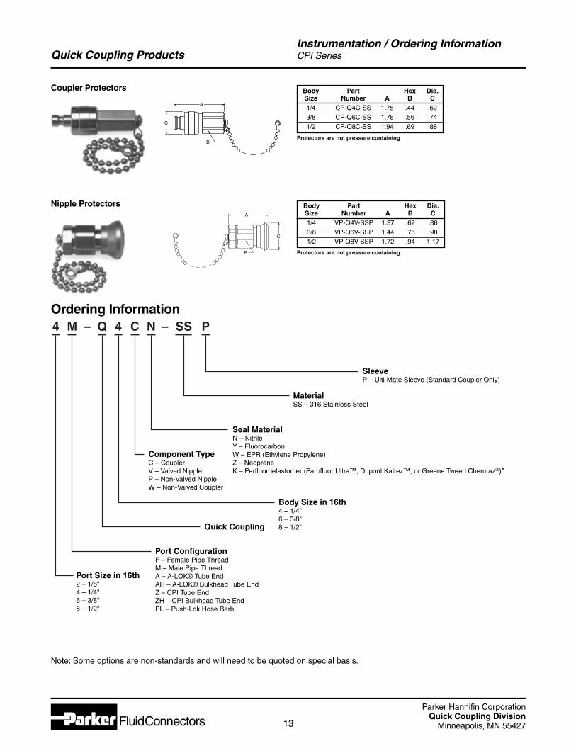
4 M – Q 4 C N – SS P
SleeveP – Ulti-Mate Sleeve (Standard Coupler Only)
Body Size in 16th4 – 1/4"6 – 3/8"8 – 1/2"
Port Size in 16th2 – 1/8"4 – 1/4"6 – 3/8"8 – 1/2"
Port ConfigurationF – Female Pipe Thread M – Male Pipe ThreadA – A-LOK® Tube EndAH – A-LOK® Bulkhead Tube EndZ – CPI Tube EndZH – CPI Bulkhead Tube EndPL – Push-Lok Hose Barb
Component TypeC – CouplerV – Valved NippleP – Non-Valved NippleW – Non-Valved Coupler
MaterialSS – 316 Stainless Steel
Seal MaterialN – NitrileY – FluorocarbonW – EPR (Ethylene Propylene)Z – NeopreneK – Perfluoroelastomer (Parofluor Ultra™, Dupont Kalrez™, or Greene Tweed Chemraz®)*
Quick Coupling
Body Part Hex Dia.Size Number A B C1/4 CP-Q4C-SS 1.75 .44 .623/8 CP-Q6C-SS 1.78 .56 .741/2 CP-Q8C-SS 1.94 .69 .88
Coupler Protectors
Ordering Information
Instrumentation / Ordering InformationCPI Series
C
B
A
Nipple Protectors Body Part Hex Dia.Size Number A B C1/4 VP-Q4V-SSP 1.37 .62 .863/8 VP-Q6V-SSP 1.44 .75 .981/2 VP-Q8V-SSP 1.72 .94 1.17
C
B
A
Note: Some options are non-standards and will need to be quoted on special basis.
Protectors are not pressure containing
Protectors are not pressure containing
Parker Hannifin CorporationQuick Coupling Division
Minneapolis, MN 5542714
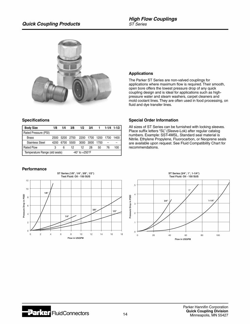
Quick Coupling ProductsHigh Flow CouplingsST Series
Applications
The Parker ST Series are non-valved couplings forapplications where maximum flow is required. Their smooth,open bore offers the lowest pressure drop of any quickcoupling design and is ideal for applications such as high-pressure water and steam washers, carpet cleaners andmold coolant lines. They are often used in food processing, onfluid and dye transfer lines.
Specifications
Body Size 1/8 1/4 3/8 1/2 3/4 1 1-1/4 1-1/2
Rated Pressure (PSI)
Brass 2500 5200 2700 2200 1700 1200 1700 1400
Stainless Steel 4200 6700 5500 3000 3000 1700 – –
Rated Flow 3 6 12 12 28 50 76 100
Temperature Range (std seals) -40° to +250°F
PerformanceST Series (3/4", 1", 1-1/4")Test Fluid: Oil - 150 SUS
0
1
2
3
4
5
0 20 40 60 80 100
Flow in USGPM
Pre
ssu
re D
rop
inP
SID
3/4"
1"
1-1/4"
ST Series (1/8", 1/4", 3/8", 1/2")Test Fluid: Oil - 150 SUS
0
2
4
6
8
10
12
0 2 4 6 8 10 12 14 16 18
Flow in USGPM
Pre
ssu
re D
rop
inP
SID
1/8"
1/4"
3/8"1/2"
Special Order Information
All sizes of ST Series can be furnished with locking sleeves.Place suffix letters “SL” (Sleeve-Lok) after regular catalognumbers. Example: SST-4MSL. Standard seal material isNitrile. Ethylene Propylene, Fluorocarbon, or Neoprene sealsare available upon request. See Fluid Compatibility Chart forrecommendations.
Parker Hannifin CorporationQuick Coupling Division
Minneapolis, MN 5542715
Quick Coupling ProductsHigh Flow CouplingsST Series
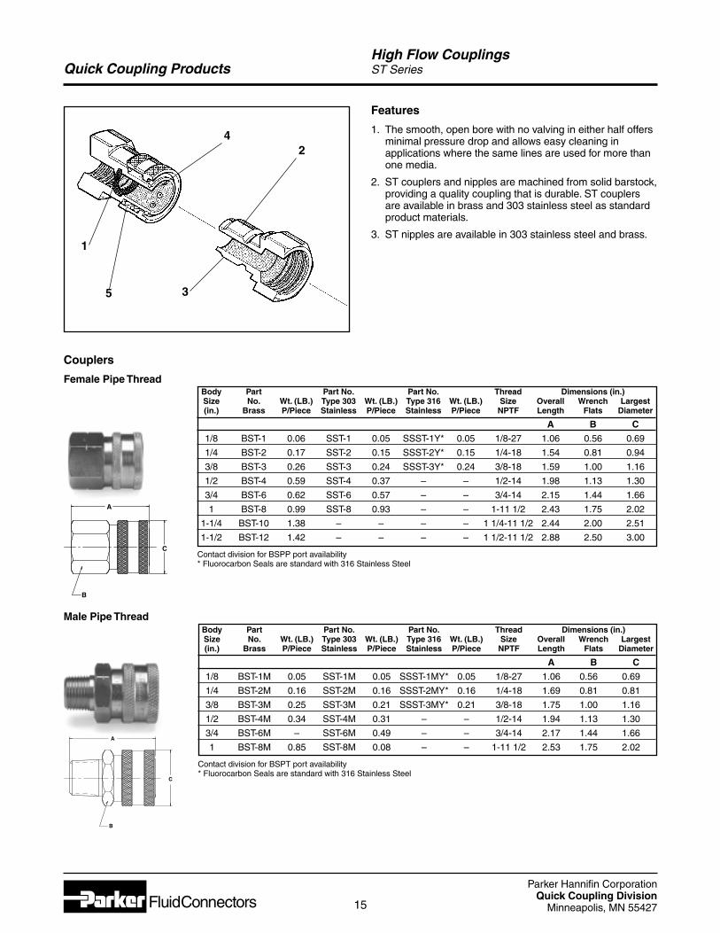
1
5 3
42
Features
1. The smooth, open bore with no valving in either half offersminimal pressure drop and allows easy cleaning inapplications where the same lines are used for more thanone media.
2. ST couplers and nipples are machined from solid barstock,providing a quality coupling that is durable. ST couplersare available in brass and 303 stainless steel as standardproduct materials.
3. ST nipples are available in 303 stainless steel and brass.
Couplers
Female Pipe Thread
Male Pipe Thread
A
C
B
A
C
B
Body Part Part No. Part No. Thread Dimensions (in.)Size No. Wt. (LB.) Type 303 Wt. (LB.) Type 316 Wt. (LB.) Size Overall Wrench Largest(in.) Brass P/Piece Stainless P/Piece Stainless P/Piece NPTF Length Flats Diameter
A B C
1/8 BST-1 0.06 SST-1 0.05 SSST-1Y* 0.05 1/8-27 1.06 0.56 0.69
1/4 BST-2 0.17 SST-2 0.15 SSST-2Y* 0.15 1/4-18 1.54 0.81 0.94
3/8 BST-3 0.26 SST-3 0.24 SSST-3Y* 0.24 3/8-18 1.59 1.00 1.16
1/2 BST-4 0.59 SST-4 0.37 – – 1/2-14 1.98 1.13 1.30
3/4 BST-6 0.62 SST-6 0.57 – – 3/4-14 2.15 1.44 1.66
1 BST-8 0.99 SST-8 0.93 – – 1-11 1/2 2.43 1.75 2.02
1-1/4 BST-10 1.38 – – – – 1 1/4-11 1/2 2.44 2.00 2.51
1-1/2 BST-12 1.42 – – – – 1 1/2-11 1/2 2.88 2.50 3.00
Contact division for BSPP port availability* Fluorocarbon Seals are standard with 316 Stainless Steel
Body Part Part No. Part No. Thread Dimensions (in.)Size No. Wt. (LB.) Type 303 Wt. (LB.) Type 316 Wt. (LB.) Size Overall Wrench Largest(in.) Brass P/Piece Stainless P/Piece Stainless P/Piece NPTF Length Flats Diameter
A B C
1/8 BST-1M 0.05 SST-1M 0.05 SSST-1MY* 0.05 1/8-27 1.06 0.56 0.69
1/4 BST-2M 0.16 SST-2M 0.16 SSST-2MY* 0.16 1/4-18 1.69 0.81 0.81
3/8 BST-3M 0.25 SST-3M 0.21 SSST-3MY* 0.21 3/8-18 1.75 1.00 1.16
1/2 BST-4M 0.34 SST-4M 0.31 – – 1/2-14 1.94 1.13 1.30
3/4 BST-6M – SST-6M 0.49 – – 3/4-14 2.17 1.44 1.66
1 BST-8M 0.85 SST-8M 0.08 – – 1-11 1/2 2.53 1.75 2.02
Contact division for BSPT port availability* Fluorocarbon Seals are standard with 316 Stainless Steel
Parker Hannifin CorporationQuick Coupling Division
Minneapolis, MN 5542716
Quick Coupling ProductsHigh Flow CouplingsST Series
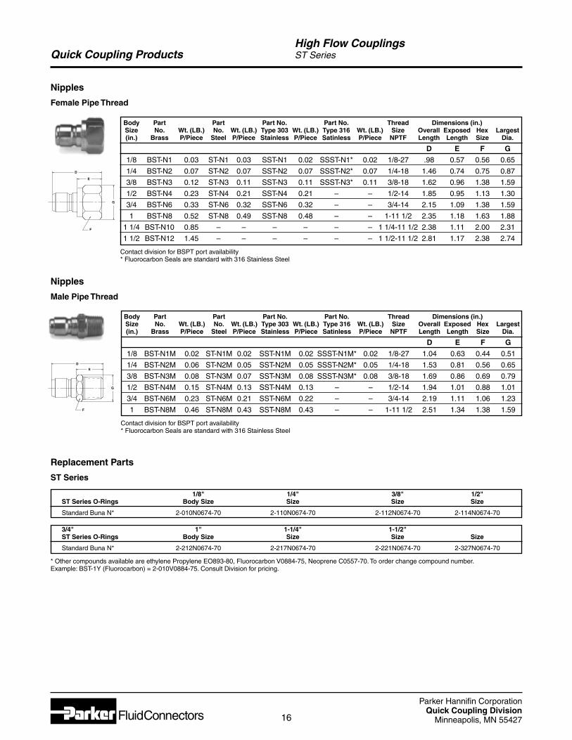
Nipples
Female Pipe Thread
D
E
G
F
Body Part Part Part No. Part No. Thread Dimensions (in.)Size No. Wt. (LB.) No. Wt. (LB.) Type 303 Wt. (LB.) Type 316 Wt. (LB.) Size Overall Exposed Hex Largest(in.) Brass P/Piece Steel P/Piece Stainless P/Piece Satinless P/Piece NPTF Length Length Size Dia.
D E F G
1/8 BST-N1 0.03 ST-N1 0.03 SST-N1 0.02 SSST-N1* 0.02 1/8-27 .98 0.57 0.56 0.65
1/4 BST-N2 0.07 ST-N2 0.07 SST-N2 0.07 SSST-N2* 0.07 1/4-18 1.46 0.74 0.75 0.87
3/8 BST-N3 0.12 ST-N3 0.11 SST-N3 0.11 SSST-N3* 0.11 3/8-18 1.62 0.96 1.38 1.59
1/2 BST-N4 0.23 ST-N4 0.21 SST-N4 0.21 – – 1/2-14 1.85 0.95 1.13 1.30
3/4 BST-N6 0.33 ST-N6 0.32 SST-N6 0.32 – – 3/4-14 2.15 1.09 1.38 1.59
1 BST-N8 0.52 ST-N8 0.49 SST-N8 0.48 – – 1-11 1/2 2.35 1.18 1.63 1.88
1 1/4 BST-N10 0.85 – – – – – – 1 1/4-11 1/2 2.38 1.11 2.00 2.31
1 1/2 BST-N12 1.45 – – – – – – 1 1/2-11 1/2 2.81 1.17 2.38 2.74
Contact division for BSPT port availability* Fluorocarbon Seals are standard with 316 Stainless Steel
Body Part Part Part No. Part No. Thread Dimensions (in.)Size No. Wt. (LB.) No. Wt. (LB.) Type 303 Wt. (LB.) Type 316 Wt. (LB.) Size Overall Exposed Hex Largest(in.) Brass P/Piece Steel P/Piece Stainless P/Piece Satinless P/Piece NPTF Length Length Size Dia.
D E F G
1/8 BST-N1M 0.02 ST-N1M 0.02 SST-N1M 0.02 SSST-N1M* 0.02 1/8-27 1.04 0.63 0.44 0.51
1/4 BST-N2M 0.06 ST-N2M 0.05 SST-N2M 0.05 SSST-N2M* 0.05 1/4-18 1.53 0.81 0.56 0.65
3/8 BST-N3M 0.08 ST-N3M 0.07 SST-N3M 0.08 SSST-N3M* 0.08 3/8-18 1.69 0.86 0.69 0.79
1/2 BST-N4M 0.15 ST-N4M 0.13 SST-N4M 0.13 – – 1/2-14 1.94 1.01 0.88 1.01
3/4 BST-N6M 0.23 ST-N6M 0.21 SST-N6M 0.22 – – 3/4-14 2.19 1.11 1.06 1.23
1 BST-N8M 0.46 ST-N8M 0.43 SST-N8M 0.43 – – 1-11 1/2 2.51 1.34 1.38 1.59
Contact division for BSPT port availability* Fluorocarbon Seals are standard with 316 Stainless Steel
Nipples
Male Pipe Thread
D
E
G
F
3/4" 1" 1-1/4" 1-1/2"ST Series O-Rings Body Size Size Size Size
Standard Buna N* 2-212N0674-70 2-217N0674-70 2-221N0674-70 2-327N0674-70
* Other compounds available are ethylene Propylene EO893-80, Fluorocarbon V0884-75, Neoprene C0557-70. To order change compound number.Example: BST-1Y (Fluorocarbon) = 2-010V0884-75. Consult Division for pricing.
1/8" 1/4" 3/8" 1/2"ST Series O-Rings Body Size Size Size Size
Standard Buna N* 2-010N0674-70 2-110N0674-70 2-112N0674-70 2-114N0674-70
Replacement Parts
ST Series
Parker Hannifin CorporationQuick Coupling Division
Minneapolis, MN 5542717
Quick Coupling ProductsGeneral Purpose Couplings60 Series
Applications
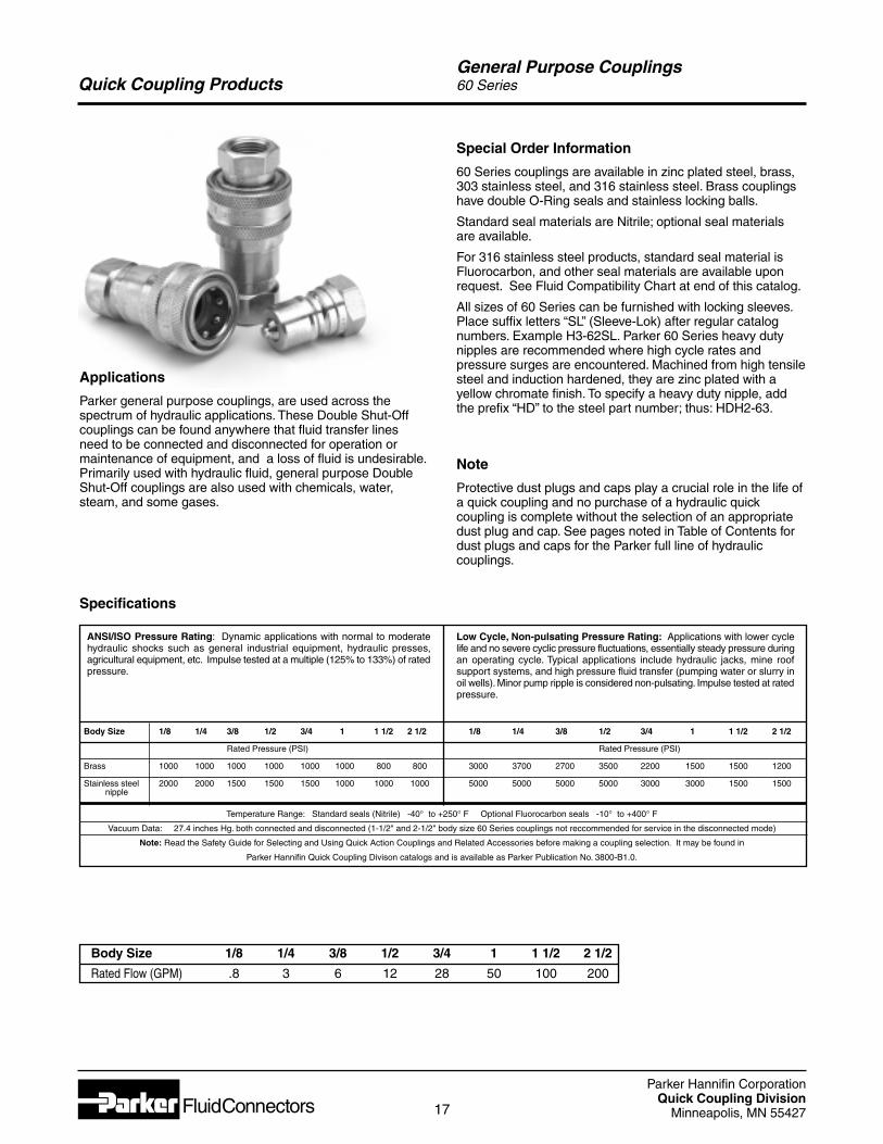
Parker general purpose couplings, are used across thespectrum of hydraulic applications. These Double Shut-Offcouplings can be found anywhere that fluid transfer linesneed to be connected and disconnected for operation ormaintenance of equipment, and a loss of fluid is undesirable.Primarily used with hydraulic fluid, general purpose DoubleShut-Off couplings are also used with chemicals, water,steam, and some gases.
Special Order Information
60 Series couplings are available in zinc plated steel, brass,303 stainless steel, and 316 stainless steel. Brass couplingshave double O-Ring seals and stainless locking balls.
Standard seal materials are Nitrile; optional seal materialsare available.
For 316 stainless steel products, standard seal material isFluorocarbon, and other seal materials are available uponrequest. See Fluid Compatibility Chart at end of this catalog.
All sizes of 60 Series can be furnished with locking sleeves.Place suffix letters “SL” (Sleeve-Lok) after regular catalognumbers. Example H3-62SL. Parker 60 Series heavy dutynipples are recommended where high cycle rates andpressure surges are encountered. Machined from high tensilesteel and induction hardened, they are zinc plated with ayellow chromate finish. To specify a heavy duty nipple, addthe prefix “HD” to the steel part number; thus: HDH2-63.
Note
Protective dust plugs and caps play a crucial role in the life ofa quick coupling and no purchase of a hydraulic quickcoupling is complete without the selection of an appropriatedust plug and cap. See pages noted in Table of Contents fordust plugs and caps for the Parker full line of hydrauliccouplings.
Body Size 1/8 1/4 3/8 1/2 3/4 1 1 1/2 2 1/2
Rated Pressure (PSI)
Brass 1000 1000 1000 1000 1000 1000 800 800
Stainless steel 2000 2000 1500 1500 1500 1000 1000 1000nipple
Temperature Range: Standard seals (Nitrile) -40° to +250° F Optional Fluorocarbon seals -10° to +400° F
Vacuum Data: 27.4 inches Hg. both connected and disconnected (1-1/2" and 2-1/2" body size 60 Series couplings not reccommended for service in the disconnected mode)
Note: Read the Safety Guide for Selecting and Using Quick Action Couplings and Related Accessories before making a coupling selection. It may be found in
Parker Hannifin Quick Coupling Divison catalogs and is available as Parker Publication No. 3800-B1.0.
Low Cycle, Non-pulsating Pressure Rating: Applications with lower cyclelife and no severe cyclic pressure fluctuations, essentially steady pressure duringan operating cycle. Typical applications include hydraulic jacks, mine roofsupport systems, and high pressure fluid transfer (pumping water or slurry inoil wells). Minor pump ripple is considered non-pulsating. Impulse tested at ratedpressure.
Specifications
ANSI/ISO Pressure Rating: Dynamic applications with normal to moderatehydraulic shocks such as general industrial equipment, hydraulic presses,agricultural equipment, etc. Impulse tested at a multiple (125% to 133%) of ratedpressure.
1/8 1/4 3/8 1/2 3/4 1 1 1/2 2 1/2
Rated Pressure (PSI)
3000 3700 2700 3500 2200 1500 1500 1200
5000 5000 5000 5000 3000 3000 1500 1500
Body Size 1/8 1/4 3/8 1/2 3/4 1 1 1/2 2 1/2
Rated Flow (GPM) .8 3 6 12 28 50 100 200
Parker Hannifin CorporationQuick Coupling Division
Minneapolis, MN 5542718
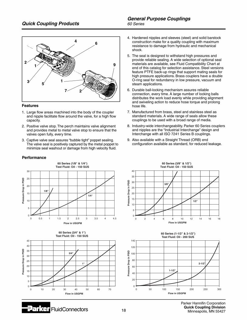
Quick Coupling ProductsGeneral Purpose Couplings60 Series
2
6
3
1
51
7 2
9
4
Features
1. Large flow areas machined into the body of the couplerand nipple facilitate flow around the valve, for a high flowcapacity.
2. Positive valve stop. The perch maintains valve alignmentand provides metal to metal valve stop to ensure that thevalves open fully, every time.
3. Captive valve seal assures “bubble tight” poppet sealing.The valve seal is positively captured by the metal poppet tominimize seal washout or damage from high velocity fluid.
4. Hardened nipples and sleeves (steel) and solid barstockconstruction make for a quality coupling with maximumresistance to damage from hydraulic and mechanicalshock.
5. The seal is designed to withstand high pressures andprovide reliable sealing. A wide selection of optional sealmaterials are available, see Fluid Compatibility Chart atend of this catalog for selection assistance. Steel versionsfeature PTFE back-up rings that support mating seals forhigh pressure applications. Brass couplers have a doubleO-ring seal for redundancy in low pressure, vacuum andsteam applications.
6. Durable ball-locking mechanism assures reliableconnection, every time. A large number of locking ballsdistributes the work load evenly while providing alignmentand swiveling action to reduce hose torque and prolonghose life.
7. Manufactured from brass, steel and stainless steel asstandard materials. A wide range of seals allow thesecouplings to be used with a broad range of media.
8. Industry-wide interchangeability. Parker 60 Series couplersand nipples are the “Industrial Interchange” design andInterchange with all ISO 7241 Series B couplings.
9. Also available with a Straight Thread (ORB) endconfiguration available as standard, for reduced leakage.
Performance60 Series (3/8" & 1/2")
Test Fluid: Oil - 150 SUS
0
5
10
15
20
25
30
35
40
0 2 4 6 8 10 12 14 16 18
Flow in USGPM
Pre
ssu
re D
rop
inP
SID
3/8"
1/2"
60 Series (1/8" & 1/4")Test Fluid: Oil - 150 SUS
0
5
10
15
20
25
30
0 0.5 1 1.5 2 2.5 3 3.5 4 4.5
Flow in USGPM
Pre
ssu
re D
rop
inP
SID
1/8"
1/4"
60 Series (3/4" & 1")Test Fluid: Oil - 150 SUS
0
5
10
15
20
25
30
35
40
45
0 10 20 30 40 50 60 70
Flow in USGPM
Pre
ssu
re D
rop
inP
SID
3/4"
1"
60 Series (1-1/2" & 2-1/2")Test Fluid: Oil - 200 SUS
0
20
40
60
80
100
120
140
0 50 100 150 200 250 300
Flow in USGPM
Pre
ssu
re D
rop
inP
SID
1-1/2"
2-1/2"
Parker Hannifin CorporationQuick Coupling Division
Minneapolis, MN 5542719
Quick Coupling ProductsGeneral Purpose Couplings60 Series
Dust Protectors
60 Series
Body Dust Plug Dust Plug Dust Cap Dust CapSize Part No. Part No. Part No. Part No.(in.) Aluminum Geolast Aluminum Geolast
1/8 H1-65 H1-65M H1-66 H1-66M1/4 H2-65 H2-65M H2-66 H2-66M3/8 H3-65 H3-65M H3-66 H3-66M1/2 H4-65 H4-65M H4-66 H4-66M3/4 H6-65 H6-65M H6-66 H6-66M1 H8-65 H8-65M H8-66 H8-66M
1 1/2 H12-65 NA H12-66 NA
NA = Not Available
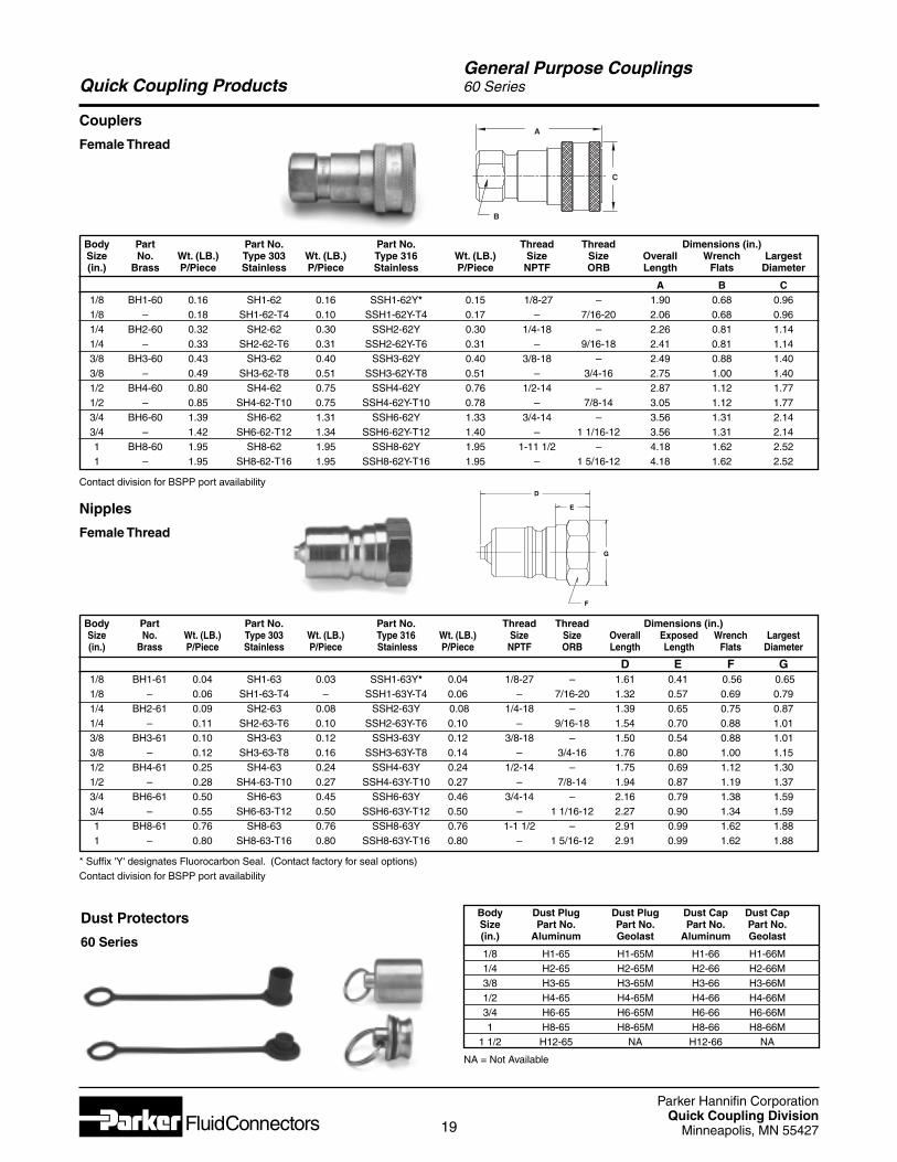
Couplers
Female Thread
Body Part Part No. Part No. Thread Thread Dimensions (in.)Size No. Wt. (LB.) Type 303 Wt. (LB.) Type 316 Wt. (LB.) Size Size Overall Exposed Wrench Largest(in.) Brass P/Piece Stainless P/Piece Stainless P/Piece NPTF ORB Length Length Flats Diameter
D E F G1/8 BH1-61 0.04 SH1-63 0.03 SSH1-63Y* 0.04 1/8-27 – 1.61 0.41 0.56 0.651/8 – 0.06 SH1-63-T4 – SSH1-63Y-T4 0.06 – 7/16-20 1.32 0.57 0.69 0.791/4 BH2-61 0.09 SH2-63 0.08 SSH2-63Y 0.08 1/4-18 – 1.39 0.65 0.75 0.871/4 – 0.11 SH2-63-T6 0.10 SSH2-63Y-T6 0.10 – 9/16-18 1.54 0.70 0.88 1.013/8 BH3-61 0.10 SH3-63 0.12 SSH3-63Y 0.12 3/8-18 – 1.50 0.54 0.88 1.013/8 – 0.12 SH3-63-T8 0.16 SSH3-63Y-T8 0.14 – 3/4-16 1.76 0.80 1.00 1.151/2 BH4-61 0.25 SH4-63 0.24 SSH4-63Y 0.24 1/2-14 – 1.75 0.69 1.12 1.301/2 – 0.28 SH4-63-T10 0.27 SSH4-63Y-T10 0.27 – 7/8-14 1.94 0.87 1.19 1.373/4 BH6-61 0.50 SH6-63 0.45 SSH6-63Y 0.46 3/4-14 – 2.16 0.79 1.38 1.593/4 – 0.55 SH6-63-T12 0.50 SSH6-63Y-T12 0.50 – 1 1/16-12 2.27 0.90 1.34 1.591 BH8-61 0.76 SH8-63 0.76 SSH8-63Y 0.76 1-1 1/2 – 2.91 0.99 1.62 1.881 – 0.80 SH8-63-T16 0.80 SSH8-63Y-T16 0.80 – 1 5/16-12 2.91 0.99 1.62 1.88
* Suffix 'Y' designates Fluorocarbon Seal. (Contact factory for seal options)Contact division for BSPP port availability
Body Part Part No. Part No. Thread Thread Dimensions (in.)Size No. Wt. (LB.) Type 303 Wt. (LB.) Type 316 Wt. (LB.) Size Size Overall Wrench Largest(in.) Brass P/Piece Stainless P/Piece Stainless P/Piece NPTF ORB Length Flats Diameter
A B C1/8 BH1-60 0.16 SH1-62 0.16 SSH1-62Y* 0.15 1/8-27 – 1.90 0.68 0.961/8 – 0.18 SH1-62-T4 0.10 SSH1-62Y-T4 0.17 – 7/16-20 2.06 0.68 0.961/4 BH2-60 0.32 SH2-62 0.30 SSH2-62Y 0.30 1/4-18 – 2.26 0.81 1.141/4 – 0.33 SH2-62-T6 0.31 SSH2-62Y-T6 0.31 – 9/16-18 2.41 0.81 1.143/8 BH3-60 0.43 SH3-62 0.40 SSH3-62Y 0.40 3/8-18 – 2.49 0.88 1.403/8 – 0.49 SH3-62-T8 0.51 SSH3-62Y-T8 0.51 – 3/4-16 2.75 1.00 1.401/2 BH4-60 0.80 SH4-62 0.75 SSH4-62Y 0.76 1/2-14 – 2.87 1.12 1.771/2 – 0.85 SH4-62-T10 0.75 SSH4-62Y-T10 0.78 – 7/8-14 3.05 1.12 1.773/4 BH6-60 1.39 SH6-62 1.31 SSH6-62Y 1.33 3/4-14 – 3.56 1.31 2.143/4 – 1.42 SH6-62-T12 1.34 SSH6-62Y-T12 1.40 – 1 1/16-12 3.56 1.31 2.141 BH8-60 1.95 SH8-62 1.95 SSH8-62Y 1.95 1-11 1/2 – 4.18 1.62 2.521 – 1.95 SH8-62-T16 1.95 SSH8-62Y-T16 1.95 – 1 5/16-12 4.18 1.62 2.52
Contact division for BSPP port availability
Nipples
Female Thread
A
C
B
D
E
G
F
Parker Hannifin CorporationQuick Coupling Division
Minneapolis, MN 5542720
Quick Coupling ProductsGeneral Purpose Couplings60 Series
Optional Seals Suffix*
W Ethylene Propylene (EPR)Y Standard Fluorocarbon SealsZ Neoprene-264 Perfluoroelastomer
Optional Seals
60 Series
NipplesRepair Kit Used ForPart No. Part No.BH67G-61K BH6-61SH67G-63K SH6-63BH67J-61K BH8-61SH67J-63K SH8-63
CouplersRepair Kit Used ForPart No. Part No.BH67G-60K BH6-60SH67G-62K SH6-62BH67J-60K BH8-60SH67J-62K SH8-62
Repair Kits
3/4" & 1" 60 Series
Body Part Part No. Part No. Thread Thread Dimensions (in.)Size No. Wt. (LB.) Type 303 Wt. (LB.) Type 316 Wt. (LB.) Size Size Overall Exposed Wrench Largest(in.) Brass P/Piece Stainless P/Piece Stainless P/Piece NPTF ORB Length Length Flats Diameter
D E F G
1 1/2 BH12-61L 2.96 SH12-63L 3.06 SSH12-63LY* – 1 1/4-11 1/2 – 4.76 2.69 2.38‡ 2.75**
1 1/2 BH12-61N 2.96 SH12-63N 3.06 SSH12-63NY – 1 1/2-11 1/2 – 4.76 2.69 2.38‡ 2.75**
1 1/2 – – SH12-63-T20 3.14 SSH12-63Y-T20 – – 1 5/8-12 4.76 2.69 2.38‡ 2.75**
1 1/2 – – SH12-63-T24 3.14 SSH12-63Y-T24 – – 1 7/8-12 4.76 2.69 2.38‡ 2.75**
2 1/2 BH2016-61 7.78 SH2016-63 7.92 SSH2016-63Y – 2-11 1/2 – 5.48 2.90 3.75 4.10
2 1/2 BH2020-61 8.12 SH2020-63 8.16 SSH2020-63Y – 2 1/2-8 – 5.95 3.37 3.75 4.10
2 1/2 BH2024-61 – SH2024-63 – SSH2024-63Y – 3-8 – 6.87 4.29 4.00 4.35
* Suffix 'Y' designates Fluorocarbon Seal. (Consult factory for seal options)** Largest diameter on Brass is 2.96" across Hex Corners‡Hex on 303 Stainless is 2.50 in.Contact division for BSPP port availability
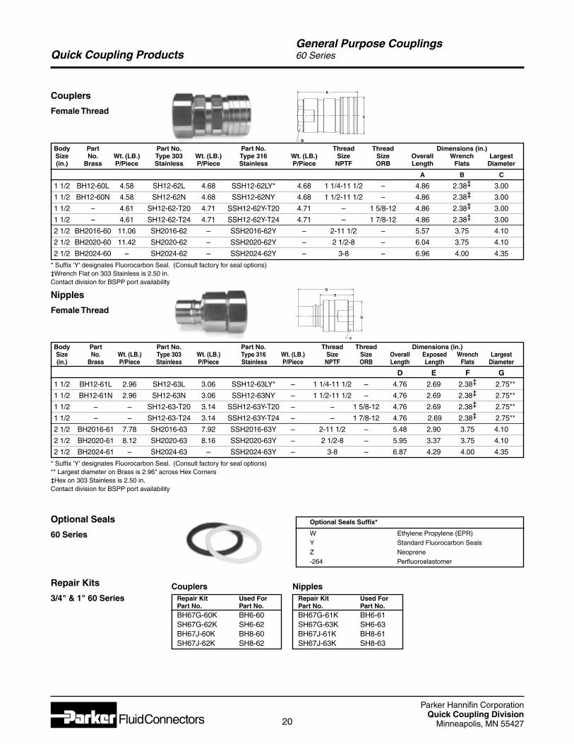
Couplers
Female ThreadC
A
B
Body Part Part No. Part No. Thread Thread Dimensions (in.)Size No. Wt. (LB.) Type 303 Wt. (LB.) Type 316 Wt. (LB.) Size Size Overall Wrench Largest(in.) Brass P/Piece Stainless P/Piece Stainless P/Piece NPTF ORB Length Flats Diameter
A B C
1 1/2 BH12-60L 4.58 SH12-62L 4.68 SSH12-62LY* 4.68 1 1/4-11 1/2 – 4.86 2.38‡ 3.00
1 1/2 BH12-60N 4.58 SH12-62N 4.68 SSH12-62NY 4.68 1 1/2-11 1/2 – 4.86 2.38‡ 3.00
1 1/2 – 4.61 SH12-62-T20 4.71 SSH12-62Y-T20 4.71 – 1 5/8-12 4.86 2.38‡ 3.00
1 1/2 – 4.61 SH12-62-T24 4.71 SSH12-62Y-T24 4.71 – 1 7/8-12 4.86 2.38‡ 3.00
2 1/2 BH2016-60 11.06 SH2016-62 – SSH2016-62Y – 2-11 1/2 – 5.57 3.75 4.10
2 1/2 BH2020-60 11.42 SH2020-62 – SSH2020-62Y – 2 1/2-8 – 6.04 3.75 4.10
2 1/2 BH2024-60 – SH2024-62 – SSH2024-62Y – 3-8 – 6.96 4.00 4.35
* Suffix 'Y' designates Fluorocarbon Seal. (Consult factory for seal options)‡Wrench Flat on 303 Stainless is 2.50 in.Contact division for BSPP port availability
D
E
G
F
Nipples
Female Thread

Parker Hannifin CorporationQuick Coupling Division
Minneapolis, MN 5542721
Quick Coupling Products
ThermoplasticQuick
Couplings
Parker Hannifin CorporationQuick Coupling Division
Minneapolis, MN 5542722
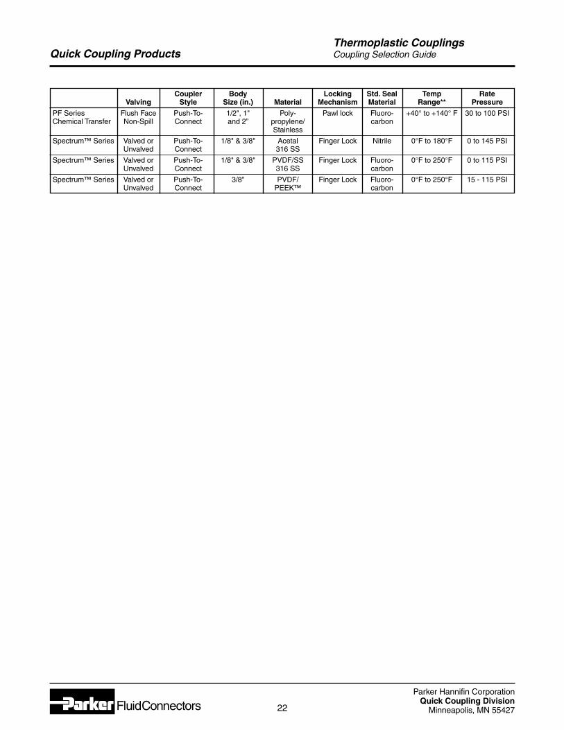
Coupler Body Locking Std. Seal Temp RateValving Style Size (in.) Material Mechanism Material Range** Pressure
PF Series Flush Face Push-To- 1/2", 1" Poly- Pawl lock Fluoro- +40° to +140° F 30 to 100 PSIChemical Transfer Non-Spill Connect and 2” propylene/ carbon
Stainless
Spectrum™ Series Valved or Push-To- 1/8" & 3/8" Acetal Finger Lock Nitrile 0°F to 180°F 0 to 145 PSIUnvalved Connect 316 SS
Spectrum™ Series Valved or Push-To- 1/8" & 3/8" PVDF/SS Finger Lock Fluoro- 0°F to 250°F 0 to 115 PSIUnvalved Connect 316 SS carbon
Spectrum™ Series Valved or Push-To- 3/8" PVDF/ Finger Lock Fluoro- 0°F to 250°F 15 - 115 PSIUnvalved Connect PEEK™ carbon
Quick Coupling ProductsThermoplastic CouplingsCoupling Selection Guide
Parker Hannifin CorporationQuick Coupling Division
Minneapolis, MN 5542723
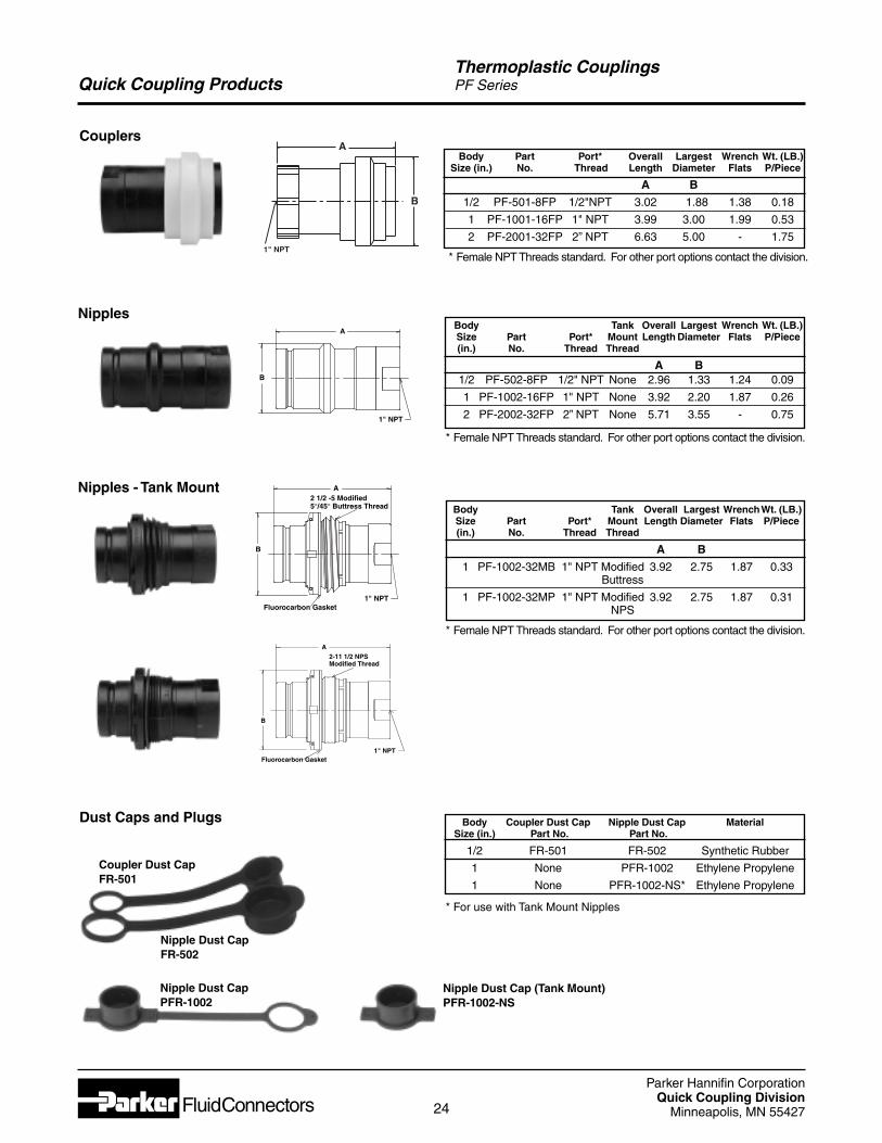
Quick Coupling ProductsThermoplastic CouplingsPF Series
Applications
• Chemical Dispensing Systems
• Spray Application Equipment
• Mini Bulk Tanks
• Replacement for Banjo Style Camlok Fittings & Ball Valves
• Bulk Transfer Barrels
Specifications
(1) Hastelloy™ & Kynar™ Coated available upon special request(2) Also available in EPDM, Nitrile, Neoprene, Parofluor
FeaturesThe Parker PF Series Dry Disconnect couplings virtuallyeliminate fluid loss upon disconnection and are designed to helpmeet the demand for closed system transfer and dispensing ofchemicals and fluids with minimal environmental contamination.They can be used with concentrated or diluted industrialchemicals, fertilizers, herbicides, insecticides, fungicides orpesticides when transferring from bulk storage tanks, returnablecontainers, applicators, etc.
New 2” Size The new PF Series 2" body size is ideal forlarge bulk transfer of fluids and eliminating fluid spillage whenconnecting and disconnecting.
Additional features include:• Rugged Glass filled Polypropylene construction for
chemical compatibility and reduced cost.
• Push-to-connect design.
• Flush face valves exhibit minimal spillage upon connect ordisconnect and air inclusion on connect, and enables easeof cleaning.
• PTFE coated Fluorocarbon tank gasket for improvedchemical compatiblity.
• 1" coupler has non-wetted springs. Spring options available for nipples include: hastelloy springs designated -640, or kynar coated springs designated -714 .
Body Size 1/2" 1" 2”
Materials:Body Polypropylene(1)
Springs 316 Stainless Steel(2)
Seals Fluorocarbon
Rated Pressure 100 PSI 60 PSI 100 PSI(at 68° F)
Rated Flow 12 GPM 20 GPM 50 GPM
Pressure Drop 11.3 PSI 3.4 PSI 4 PSIat Rated Flow
Force to Connect 32 lbs. 54 lbs. 41 lbs.
Force to Disconnect 12 lbs. 17 lbs. 17 lbs.
Operating Temp. +40°F to +140° F
Storage Temp. -20°F to +140° F
Maximum Spillage 0.14 ml 1ml 9 mlper Disconnect .01 cu. in. .06 cu. in. (1cc) .5 cu. in.
Vacuum Rating 27.4 Hg Contact Factory Contact Factory
PF (1/2", 1", 2")Test Fluid: Water
0
5
10
15
20
25
0 10 20 30 40 50 60 70Flow in USGPM
Pre
ssu
re D
rop
in P
SID
1/2"
1"
2"
Performance
Parker Hannifin CorporationQuick Coupling Division
Minneapolis, MN 5542724
Quick Coupling ProductsThermoplastic CouplingsPF Series
Nipple Dust CapFR-502
Coupler Dust CapFR-501
Body Tank Overall Largest Wrench Wt. (LB.)Size Part Port* Mount Length Diameter Flats P/Piece(in.) No. Thread Thread
A B1/2 PF-502-8FP 1/2" NPT None 2.96 1.33 1.24 0.09
1 PF-1002-16FP 1" NPT None 3.92 2.20 1.87 0.26
2 PF-2002-32FP 2” NPT None 5.71 3.55 - 0.75
* Female NPT Threads standard. For other port options contact the division.
Dust Caps and Plugs
A
B
1" NPT
Nipples
A
B
1" NPT
2-11 1/2 NPSModified Thread
Fluorocarbon Gasket
CouplersA
B
1" NPT
Nipple Dust CapPFR-1002
Nipple Dust Cap (Tank Mount)PFR-1002-NS
Body Tank Overall Largest WrenchWt. (LB.)Size Part Port* Mount Length Diameter Flats P/Piece(in.) No. Thread Thread
A B
1 PF-1002-32MB 1" NPT Modified 3.92 2.75 1.87 0.33Buttress
1 PF-1002-32MP 1" NPT Modified 3.92 2.75 1.87 0.31NPS
* Female NPT Threads standard. For other port options contact the division.
A
B
1" NPT
2 1/2 -5 Modified5°/45° Buttress Thread
Fluorocarbon Gasket
Body Part Port* Overall Largest Wrench Wt. (LB.)Size (in.) No. Thread Length Diameter Flats P/Piece
A B
1/2 PF-501-8FP 1/2"NPT 3.02 1.88 1.38 0.18
1 PF-1001-16FP 1" NPT 3.99 3.00 1.99 0.53
2 PF-2001-32FP 2” NPT 6.63 5.00 - 1.75
* Female NPT Threads standard. For other port options contact the division.
* For use with Tank Mount Nipples
Nipples - Tank Mount
Body Coupler Dust Cap Nipple Dust Cap MaterialSize (in.) Part No. Part No.
1/2 FR-501 FR-502 Synthetic Rubber
1 None PFR-1002 Ethylene Propylene
1 None PFR-1002-NS* Ethylene Propylene
Parker Hannifin CorporationQuick Coupling Division
Minneapolis, MN 5542725
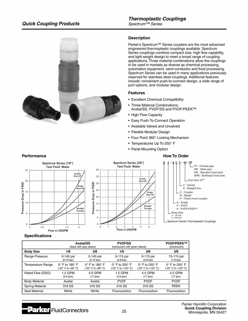
Quick Coupling ProductsThermoplastic CouplingsSpectrum™ Series
Description
Parker’s Spectrum™ Series couplers are the most advancedengineered thermoplastic couplings available. SpectrumSeries couplings combine compact size, high flow capability,and light weight design to meet a broad range of couplingapplications. Three material combinations allow the couplingsto be used in markets as diverse as chemical processing,automation equipment, semi-conductor and food processing.Spectrum Series can be used in many applications previouslyreserved for stainless steel couplings. Additional featuresinclude: convenient push-to-connect design, a wide range ofport options, and modular design.
Features
• Excellent Chemical Compatibility
• Three Material Combinations:Acetal/SS, PVDF/SS and PVDF/PEEK™
• High Flow Capacity
• Easy Push-To-Connect Operation
• Available Valved and Unvalved
• Flexible Modular Design
• Four Point 360° Locking Mechanism
• Temperatures Up To 250° F
• Panel Mounting Option
Performance
Specifications
Acetal/SS PVDF/SS PVDF/PEEK™(black with grey sleeve) (translucent with green sleeve) (translucent)
Body Size 1/8 3/8 1/8 3/8 3/8
Range Pressure 0-145 psi 0-145 psi 0-115 psi 0-115 psi 15-115 psi(0-10 bar) (0-10 bar) (0-8 bar) (0-8 bar) (1-8 bar)
Temperature Range 0° F to 180° F 0° F to 180° F 0° F to 250° F 0° F to 250° F 0° F to 250° F(-20° C to +80° C) (-20° C to +80° C) (-20° C to +120° C) (-20° C to +120° C) (-20° C to +120° C)
Rated Flow (DSO) 1.5 GPM 4.5 GPM 1.5 GPM 4.5 GPM 4.5 GPM(5.6 lpm) (17 lpm) (5.6 lpm) (17 lpm) (17 lpm)
Body Material Acetal Acetal PVDF PVDF PVDF
Spring Material 316 SS 316 SS 316 SS 316 SS PEEK
Seal Material Nitrile Nitrile Fluorocarbon Fluorocarbon Fluorocarbon
Spectrum Series (1/8")Test Fluid: Water
0
5
10
15
20
25
0 0.5 1 1.5 2
Flow in USGPM
Pre
ss
ure
Dro
p in
PS
ID
DoubleShut Off
SingleShut Off
StraightThrough
Spectrum Series (3/8")Test Fluid: Water
0
5
10
15
20
25
30
35
40
0 1 2 3 4 5 6Flow in USGPM
Pre
ss
ure
Dro
p in
PS
ID
DoubleShut Off
SingleShut Off
StraightThrough
2 C V
V - Valved S - Straight thru
Body Size 2 - 1/8 Inch 6 - 3/8 Inch
C - Coupler N - Nipple P - Panel mount coupler
A
A - Acetal P - PVDF K - PVDF/PEEK™
04 - FP-FP - Female pipe
MP - Male pipe HB - Standard hose barb BHB - Bulkhead hose barb
Port Size 16ths
-S
Spectrum Series Thermoplastic Couplings
How To Order
Parker Hannifin CorporationQuick Coupling Division
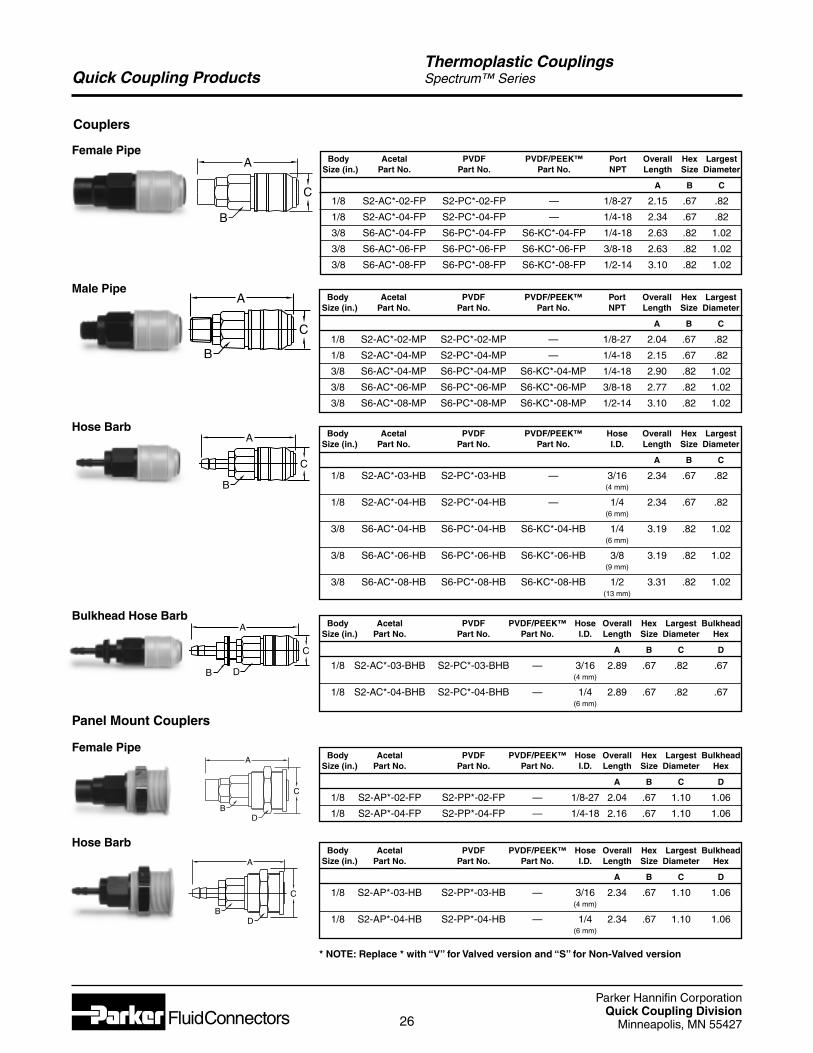
Minneapolis, MN 5542726
Quick Coupling Products
Couplers
Body Acetal PVDF PVDF/PEEK™ Port Overall Hex LargestSize (in.) Part No. Part No. Part No. NPT Length Size Diameter
A B C
1/8 S2-AC*-02-MP S2-PC*-02-MP — 1/8-27 2.04 .67 .82
1/8 S2-AC*-04-MP S2-PC*-04-MP — 1/4-18 2.15 .67 .82
3/8 S6-AC*-04-MP S6-PC*-04-MP S6-KC*-04-MP 1/4-18 2.90 .82 1.02
3/8 S6-AC*-06-MP S6-PC*-06-MP S6-KC*-06-MP 3/8-18 2.77 .82 1.02
3/8 S6-AC*-08-MP S6-PC*-08-MP S6-KC*-08-MP 1/2-14 3.10 .82 1.02
Male Pipe
Body Acetal PVDF PVDF/PEEK™ Port Overall Hex LargestSize (in.) Part No. Part No. Part No. NPT Length Size Diameter
A B C
1/8 S2-AC*-02-FP S2-PC*-02-FP — 1/8-27 2.15 .67 .82
1/8 S2-AC*-04-FP S2-PC*-04-FP — 1/4-18 2.34 .67 .82
3/8 S6-AC*-04-FP S6-PC*-04-FP S6-KC*-04-FP 1/4-18 2.63 .82 1.02
3/8 S6-AC*-06-FP S6-PC*-06-FP S6-KC*-06-FP 3/8-18 2.63 .82 1.02
3/8 S6-AC*-08-FP S6-PC*-08-FP S6-KC*-08-FP 1/2-14 3.10 .82 1.02
Female Pipe
Thermoplastic CouplingsSpectrum™ Series
Body Acetal PVDF PVDF/PEEK™ Hose Overall Hex LargestSize (in.) Part No. Part No. Part No. I.D. Length Size Diameter
A B C
1/8 S2-AC*-03-HB S2-PC*-03-HB — 3/16 2.34 .67 .82(4 mm)
1/8 S2-AC*-04-HB S2-PC*-04-HB — 1/4 2.34 .67 .82(6 mm)
3/8 S6-AC*-04-HB S6-PC*-04-HB S6-KC*-04-HB 1/4 3.19 .82 1.02(6 mm)
3/8 S6-AC*-06-HB S6-PC*-06-HB S6-KC*-06-HB 3/8 3.19 .82 1.02(9 mm)
3/8 S6-AC*-08-HB S6-PC*-08-HB S6-KC*-08-HB 1/2 3.31 .82 1.02(13 mm)
Hose Barb
Body Acetal PVDF PVDF/PEEK™ Hose Overall Hex Largest BulkheadSize (in.) Part No. Part No. Part No. I.D. Length Size Diameter Hex
A B C D
1/8 S2-AC*-03-BHB S2-PC*-03-BHB — 3/16 2.89 .67 .82 .67(4 mm)
1/8 S2-AC*-04-BHB S2-PC*-04-BHB — 1/4 2.89 .67 .82 .67(6 mm)
Bulkhead Hose Barb
Panel Mount Couplers
Body Acetal PVDF PVDF/PEEK™ Hose Overall Hex Largest BulkheadSize (in.) Part No. Part No. Part No. I.D. Length Size Diameter Hex
A B C D
1/8 S2-AP*-03-HB S2-PP*-03-HB — 3/16 2.34 .67 1.10 1.06(4 mm)
1/8 S2-AP*-04-HB S2-PP*-04-HB — 1/4 2.34 .67 1.10 1.06(6 mm)
Hose Barb
Body Acetal PVDF PVDF/PEEK™ Hose Overall Hex Largest BulkheadSize (in.) Part No. Part No. Part No. I.D. Length Size Diameter Hex
A B C D
1/8 S2-AP*-02-FP S2-PP*-02-FP — 1/8-27 2.04 .67 1.10 1.06
1/8 S2-AP*-04-FP S2-PP*-04-FP — 1/4-18 2.16 .67 1.10 1.06
Female Pipe
C
B
A
C
B
A
C
B
A
C
B D
A
C
BD
A
C
BD
A
* NOTE: Replace * with “V” for Valved version and “S” for Non-Valved version
Parker Hannifin CorporationQuick Coupling Division
Minneapolis, MN 5542727
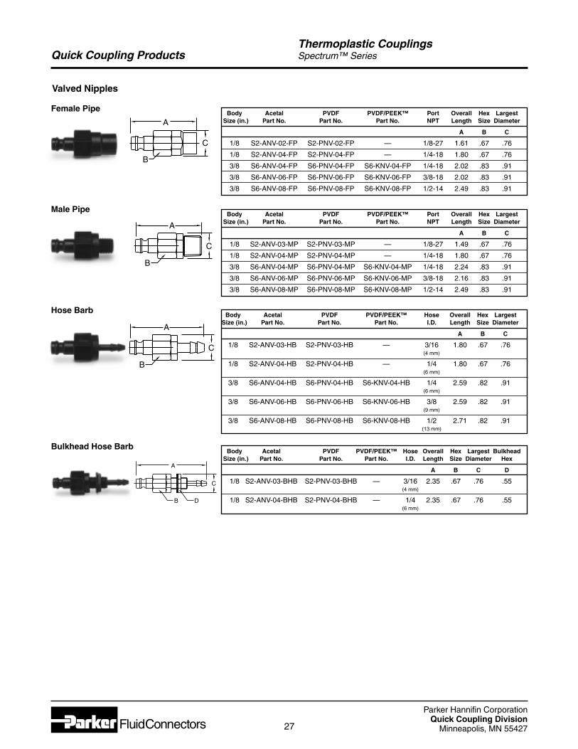
Quick Coupling Products
Body Acetal PVDF PVDF/PEEK™ Port Overall Hex LargestSize (in.) Part No. Part No. Part No. NPT Length Size Diameter
A B C
1/8 S2-ANV-03-MP S2-PNV-03-MP — 1/8-27 1.49 .67 .76
1/8 S2-ANV-04-MP S2-PNV-04-MP — 1/4-18 1.80 .67 .76
3/8 S6-ANV-04-MP S6-PNV-04-MP S6-KNV-04-MP 1/4-18 2.24 .83 .91
3/8 S6-ANV-06-MP S6-PNV-06-MP S6-KNV-06-MP 3/8-18 2.16 .83 .91
3/8 S6-ANV-08-MP S6-PNV-08-MP S6-KNV-08-MP 1/2-14 2.49 .83 .91
Thermoplastic CouplingsSpectrum™ Series
Body Acetal PVDF PVDF/PEEK™ Hose Overall Hex LargestSize (in.) Part No. Part No. Part No. I.D. Length Size Diameter
A B C
1/8 S2-ANV-03-HB S2-PNV-03-HB — 3/16 1.80 .67 .76(4 mm)
1/8 S2-ANV-04-HB S2-PNV-04-HB — 1/4 1.80 .67 .76(6 mm)
3/8 S6-ANV-04-HB S6-PNV-04-HB S6-KNV-04-HB 1/4 2.59 .82 .91(6 mm)
3/8 S6-ANV-06-HB S6-PNV-06-HB S6-KNV-06-HB 3/8 2.59 .82 .91(9 mm)
3/8 S6-ANV-08-HB S6-PNV-08-HB S6-KNV-08-HB 1/2 2.71 .82 .91(13 mm)
Hose Barb
Body Acetal PVDF PVDF/PEEK™ Hose Overall Hex Largest BulkheadSize (in.) Part No. Part No. Part No. I.D. Length Size Diameter Hex
A B C D
1/8 S2-ANV-03-BHB S2-PNV-03-BHB — 3/16 2.35 .67 .76 .55(4 mm)
1/8 S2-ANV-04-BHB S2-PNV-04-BHB — 1/4 2.35 .67 .76 .55(6 mm)
Bulkhead Hose Barb
Valved Nipples
Male Pipe
Body Acetal PVDF PVDF/PEEK™ Port Overall Hex LargestSize (in.) Part No. Part No. Part No. NPT Length Size Diameter
A B C
1/8 S2-ANV-02-FP S2-PNV-02-FP — 1/8-27 1.61 .67 .76
1/8 S2-ANV-04-FP S2-PNV-04-FP — 1/4-18 1.80 .67 .76
3/8 S6-ANV-04-FP S6-PNV-04-FP S6-KNV-04-FP 1/4-18 2.02 .83 .91
3/8 S6-ANV-06-FP S6-PNV-06-FP S6-KNV-06-FP 3/8-18 2.02 .83 .91
3/8 S6-ANV-08-FP S6-PNV-08-FP S6-KNV-08-FP 1/2-14 2.49 .83 .91
Female Pipe
C
B D
A
C
B
A
C
B
A
C
B
A
Parker Hannifin CorporationQuick Coupling Division
Minneapolis, MN 5542728
Quick Coupling Products
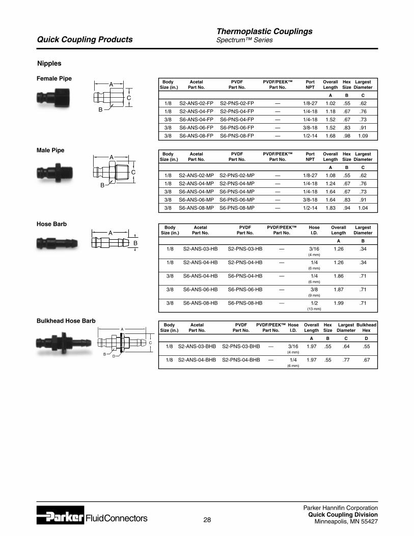
Nipples
Body Acetal PVDF PVDF/PEEK™ Port Overall Hex LargestSize (in.) Part No. Part No. Part No. NPT Length Size Diameter
A B C
1/8 S2-ANS-02-MP S2-PNS-02-MP — 1/8-27 1.08 .55 .62
1/8 S2-ANS-04-MP S2-PNS-04-MP — 1/4-18 1.24 .67 .76
3/8 S6-ANS-04-MP S6-PNS-04-MP — 1/4-18 1.64 .67 .73
3/8 S6-ANS-06-MP S6-PNS-06-MP — 3/8-18 1.64 .83 .91
3/8 S6-ANS-08-MP S6-PNS-08-MP — 1/2-14 1.83 .94 1.04
Male Pipe
Thermoplastic CouplingsSpectrum™ Series
Body Acetal PVDF PVDF/PEEK™ Port Overall Hex LargestSize (in.) Part No. Part No. Part No. NPT Length Size Diameter
A B C
1/8 S2-ANS-02-FP S2-PNS-02-FP — 1/8-27 1.02 .55 .62
1/8 S2-ANS-04-FP S2-PNS-04-FP — 1/4-18 1.18 .67 .76
3/8 S6-ANS-04-FP S6-PNS-04-FP — 1/4-18 1.52 .67 .73
3/8 S6-ANS-06-FP S6-PNS-06-FP — 3/8-18 1.52 .83 .91
3/8 S6-ANS-08-FP S6-PNS-08-FP — 1/2-14 1.68 .98 1.09
Female Pipe
Body Acetal PVDF PVDF/PEEK™ Hose Overall LargestSize (in.) Part No. Part No. Part No. I.D. Length Diameter
A B
1/8 S2-ANS-03-HB S2-PNS-03-HB — 3/16 1.26 .34(4 mm)
1/8 S2-ANS-04-HB S2-PNS-04-HB — 1/4 1.26 .34(6 mm)
3/8 S6-ANS-04-HB S6-PNS-04-HB — 1/4 1.86 .71(6 mm)
3/8 S6-ANS-06-HB S6-PNS-06-HB — 3/8 1.87 .71(9 mm)
3/8 S6-ANS-08-HB S6-PNS-08-HB — 1/2 1.99 .71(13 mm)
Hose Barb
Body Acetal PVDF PVDF/PEEK™ Hose Overall Hex Largest BulkheadSize (in.) Part No. Part No. Part No. I.D. Length Size Diameter Hex
A B C D
1/8 S2-ANS-03-BHB S2-PNS-03-BHB — 3/16 1.97 .55 .64 .55(4 mm)
1/8 S2-ANS-04-BHB S2-PNS-04-BHB — 1/4 1.97 .55 .77 .67(6 mm)
Bulkhead Hose Barb
C
B D
A
C
B
A
C
B
A
B
A

Parker Hannifin CorporationQuick Coupling Division
Minneapolis, MN 5542729
PneumaticQuick
Couplings
Parker Hannifin CorporationQuick Coupling Division
Minneapolis, MN 5542730
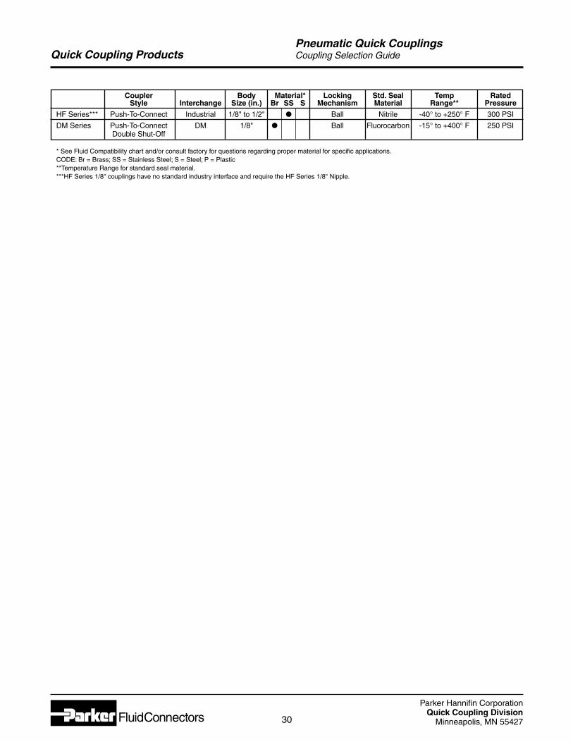
Quick Coupling ProductsPneumatic Quick CouplingsCoupling Selection Guide
Coupler Body Material* Locking Std. Seal Temp RatedStyle Interchange Size (in.) Br SS S Mechanism Material Range** Pressure
HF Series*** Push-To-Connect Industrial 1/8" to 1/2" l Ball Nitrile -40° to +250° F 300 PSI
DM Series Push-To-Connect DM 1/8" l Ball Fluorocarbon -15° to +400° F 250 PSIDouble Shut-Off
* See Fluid Compatibility chart and/or consult factory for questions regarding proper material for specific applications.CODE: Br = Brass; SS = Stainless Steel; S = Steel; P = Plastic**Temperature Range for standard seal material.***HF Series 1/8" couplings have no standard industry interface and require the HF Series 1/8" Nipple.
Parker Hannifin CorporationQuick Coupling Division
Minneapolis, MN 5542731
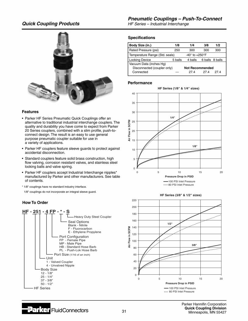
Quick Coupling ProductsPneumatic Couplings – Push-To-ConnectHF Series – Industrial Interchange
Features
• Parker HF Series Pneumatic Quick Couplings offer analternative to traditional industrial interchange couplers. Thequality and durability you have come to expect from Parker20 Series couplers, combined with a slim profile, push-to-connect design. The result is an easy to use generalpurpose pneumatic coupler suitable for use in a variety of applications.
• Parker HF couplers feature sleeve guards to protect againstaccidental disconnection.
• Standard couplers feature solid brass construction, highflow valving, corrosion resistant valves, and stainless steellocking balls and valve spring.
• Parker HF couplers accept Industrial Interchange nipples*manufactured by Parker and other manufacturers. See tableof contents.
* 1/8" couplings have no standard industry interface.
1/8" couplings do not incorporate an integral sleeve guard.
How To Order
HF Series (1/8" & 1/4" sizes)
0
5
10
15
20
25
30
35
40
0 5 10 15 20
Air
Flo
w in
SC
FM
1/4"
1/8"
Pressure Drop in PSID
100 PSI Inlet Pressure80 PSI Inlet Pressure
Performance
Specifications
Body Size (in.) 1/8 1/4 3/8 1/2
Rated Pressure (psi) 250 300 300 300
Temperature Range (Std. seals) -40° to +250°F
Locking Device 5 balls 4 balls 6 balls 8 ballsVacuum Data (inches Hg)
Disconnected (coupler only) Not RecommendedConnected — 27.4 27.4 27.4
HF Series (3/8" & 1/2" sizes)
0
20
40
60
80
100
120
140
160
180
200
220
0 5 10 15 20
Air
Flo
w in
SC
FM
1/2"
3/8"
Pressure Drop in PSID
100 PSI Inlet Pressure80 PSI Inlet Pressure
Port ConfigurationFP - Female PipeMP - Male PipeHB - Standard Hose BarbPL - Push-Lok Hose Barb
HF Series
Port Size (1/16 of an inch)
Body Size12 - 1/8"25 - 1/4"37 - 3/8"50 - 1/2"
HF - 251 - 4 FP - * - S
Unit1 - Valved Coupler4 - Unvalved Nipple
Heavy Duty Steel Coupler
Seal OptionsBlank - NitrileF - FluorocarbonE - Ethylene Propylene
Parker Hannifin CorporationQuick Coupling Division
Minneapolis, MN 5542732
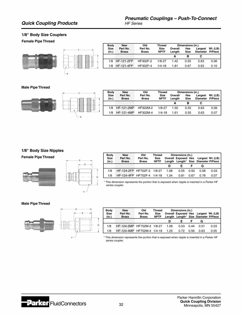
Quick Coupling ProductsPneumatic Couplings – Push-To-ConnectHF Series
D
E
G
F
Body New Old Thread Dimensions (in.)Size Part No. Part No. Size Overall Exposed Hex Largest Wt. (LB)(in.) Brass Brass NPTF Length Length* Size Diameter P/Piece
D E F G
1/8 HF-124-2FP HF702F-2 1/8-27 1.08 0.55 0.50 0.58 0.03
1/8 HF-124-4FP HF702F-4 1/4-18 1.34 0.81 0.67 0.78 0.07
* This dimension represents the portion that is exposed when nipple is inserted in a Parker HF series coupler.
Body New Old Thread Dimensions (in.)Size Part No. Part No. Size Overall Hex Largest Wt. (LB)(in.) Brass Brass NPTF Length Size Diameter P/Piece
A B C
1/8 HF-121-2FP HF302F-2 1/8-27 1.42 0.55 0.63 0.06
1/8 HF-121-4FP HF302F-4 1/4-18 1.81 0.67 0.63 0.10
Male Pipe Thread
F
G
D
E
1/8" Body Size Nipples
Female Pipe Thread
1/8" Body Size Couplers
Female Pipe Thread
Male Pipe Thread
A
C
B
A
C
B
Body New Old Thread Dimensions (in.)Size Part No. Part No. Size Overall Hex Largest Wt. (LB)(in.) Brass Brass NPTF Length Size Diameter P/Piece
A B C
1/8 HF-121-2MP HF302M-2 1/8-27 1.50 0.55 0.63 0.06
1/8 HF-121-4MP HF302M-4 1/4-18 1.61 0.55 0.63 0.07
Body New Old Thread Dimensions (in.)Size Part No. Part No. Size Overall Exposed Hex Largest Wt. (LB)(in.) Brass Brass NPTF Length Length* Size Diameter P/Piece
D E F G
1/8 HF-124-2MP HF702M-2 1/8-27 1.06 0.53 0.44 0.51 0.03
1/8 HF-124-4MP HF702M-4 1/4-18 1.25 0.72 0.56 0.63 0.05
* This dimension represents the portion that is exposed when nipple is inserted in a Parker HF series coupler.
Parker Hannifin CorporationQuick Coupling Division
Minneapolis, MN 5542733
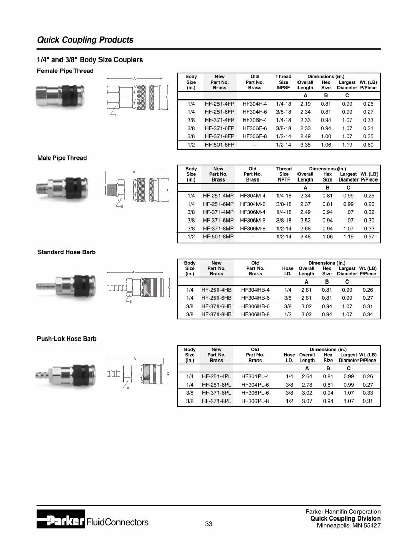
Quick Coupling Products
1/4" and 3/8" Body Size Couplers
Female Pipe Thread
Male Pipe Thread
Push-Lok Hose Barb
B
A
C
Standard Hose Barb
B
A
C
B
A
C
B
A
C
Body New Old Thread Dimensions (in.)Size Part No. Part No. Size Overall Hex Largest Wt. (LB)(in.) Brass Brass NPTF Length Size Diameter P/Piece
A B C
1/4 HF-251-4MP HF304M-4 1/4-18 2.34 0.81 0.99 0.25
1/4 HF-251-6MP HF304M-6 3/8-18 2.37 0.81 0.99 0.26
3/8 HF-371-4MP HF306M-4 1/4-18 2.49 0.94 1.07 0.32
3/8 HF-371-6MP HF306M-6 3/8-18 2.52 0.94 1.07 0.30
3/8 HF-371-8MP HF306M-8 1/2-14 2.68 0.94 1.07 0.33
1/2 HF-501-8MP – 1/2-14 3.48 1.06 1.19 0.57
Body New Old Dimensions (in.)Size Part No. Part No. Hose Overall Hex Largest Wt. (LB)(in.) Brass Brass I.D. Length Size Diameter P/Piece
A B C
1/4 HF-251-4HB HF304HB-4 1/4 2.81 0.81 0.99 0.26
1/4 HF-251-6HB HF304HB-6 3/8 2.81 0.81 0.99 0.27
3/8 HF-371-6HB HF306HB-6 3/8 3.02 0.94 1.07 0.31
3/8 HF-371-8HB HF306HB-8 1/2 3.02 0.94 1.07 0.34
Body New Old Dimensions (in.)Size Part No. Part No. Hose Overall Hex Largest Wt. (LB)(in.) Brass Brass I.D. Length Size DiameterP/Piece
A B C
1/4 HF-251-4PL HF304PL-4 1/4 2.64 0.81 0.99 0.26
1/4 HF-251-6PL HF304PL-6 3/8 2.78 0.81 0.99 0.27
3/8 HF-371-6PL HF306PL-6 3/8 3.02 0.94 1.07 0.33
3/8 HF-371-8PL HF306PL-8 1/2 3.07 0.94 1.07 0.31
Body New Old Thread Dimensions (in.)Size Part No. Part No. Size Overall Hex Largest Wt. (LB)(in.) Brass Brass NPSF Length Size Diameter P/Piece
A B C
1/4 HF-251-4FP HF304F-4 1/4-18 2.19 0.81 0.99 0.26
1/4 HF-251-6FP HF304F-6 3/8-18 2.34 0.81 0.99 0.27
3/8 HF-371-4FP HF306F-4 1/4-18 2.33 0.94 1.07 0.33
3/8 HF-371-6FP HF306F-6 3/8-18 2.33 0.94 1.07 0.31
3/8 HF-371-8FP HF306F-8 1/2-14 2.49 1.00 1.07 0.35
1/2 HF-501-8FP – 1/2-14 3.35 1.06 1.19 0.60
Parker Hannifin CorporationQuick Coupling Division
Minneapolis, MN 5542734
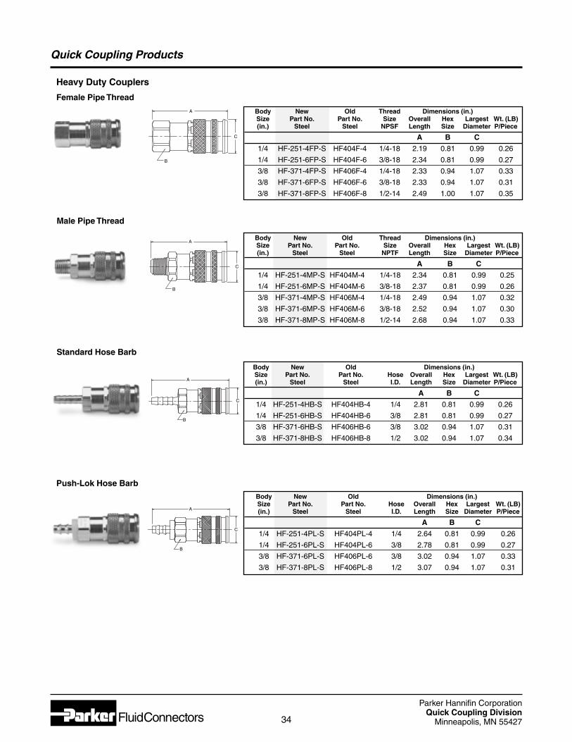
Quick Coupling Products
Body New Old Dimensions (in.)Size Part No. Part No. Hose Overall Hex Largest Wt. (LB)(in.) Steel Steel I.D. Length Size Diameter P/Piece
A B C
1/4 HF-251-4PL-S HF404PL-4 1/4 2.64 0.81 0.99 0.26
1/4 HF-251-6PL-S HF404PL-6 3/8 2.78 0.81 0.99 0.27
3/8 HF-371-6PL-S HF406PL-6 3/8 3.02 0.94 1.07 0.33
3/8 HF-371-8PL-S HF406PL-8 1/2 3.07 0.94 1.07 0.31
Body New Old Dimensions (in.)Size Part No. Part No. Hose Overall Hex Largest Wt. (LB)(in.) Steel Steel I.D. Length Size Diameter P/Piece
A B C
1/4 HF-251-4HB-S HF404HB-4 1/4 2.81 0.81 0.99 0.26
1/4 HF-251-6HB-S HF404HB-6 3/8 2.81 0.81 0.99 0.27
3/8 HF-371-6HB-S HF406HB-6 3/8 3.02 0.94 1.07 0.31
3/8 HF-371-8HB-S HF406HB-8 1/2 3.02 0.94 1.07 0.34
Body New Old Thread Dimensions (in.)Size Part No. Part No. Size Overall Hex Largest Wt. (LB)(in.) Steel Steel NPTF Length Size Diameter P/Piece
A B C
1/4 HF-251-4MP-S HF404M-4 1/4-18 2.34 0.81 0.99 0.25
1/4 HF-251-6MP-S HF404M-6 3/8-18 2.37 0.81 0.99 0.26
3/8 HF-371-4MP-S HF406M-4 1/4-18 2.49 0.94 1.07 0.32
3/8 HF-371-6MP-S HF406M-6 3/8-18 2.52 0.94 1.07 0.30
3/8 HF-371-8MP-S HF406M-8 1/2-14 2.68 0.94 1.07 0.33
Body New Old Thread Dimensions (in.)Size Part No. Part No. Size Overall Hex Largest Wt. (LB)(in.) Steel Steel NPSF Length Size Diameter P/Piece
A B C
1/4 HF-251-4FP-S HF404F-4 1/4-18 2.19 0.81 0.99 0.26
1/4 HF-251-6FP-S HF404F-6 3/8-18 2.34 0.81 0.99 0.27
3/8 HF-371-4FP-S HF406F-4 1/4-18 2.33 0.94 1.07 0.33
3/8 HF-371-6FP-S HF406F-6 3/8-18 2.33 0.94 1.07 0.31
3/8 HF-371-8FP-S HF406F-8 1/2-14 2.49 1.00 1.07 0.35
Heavy Duty Couplers
Female Pipe Thread
Male Pipe Thread
Push-Lok Hose Barb
B
A
C
Standard Hose Barb
B
A
C
B
A
C
B
A
C
Parker Hannifin CorporationQuick Coupling Division
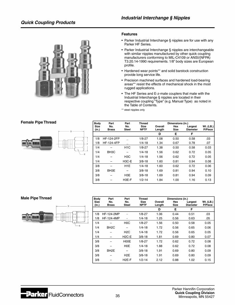
Minneapolis, MN 5542735
Quick Coupling Products
Body Part Part Thread Dimensions (in.)Size No. No. Size Overall Hex Largest Wt. (LB.)(in.) Brass Steel NPTF Length Size Diameter P/Piece
D E F
1/8 HF-124-2FP _ 1/8-27 1.08 0.50 0.58 .031/8 HF-124-4FP _ 1/4-18 1.34 0.67 0.78 .07
1/4 – H1C 1/8-27 1.38 0.50 0.58 0.03
1/4 BH3C – 1/4-18 1.56 0.62 0.72 0.05
1/4 – H3C 1/4-18 1.56 0.62 0.72 0.05
1/4 – H3C-E 3/8-18 1.60 0.81 0.94 0.08
3/8 – H1E 1/4-18 1.60 0.62 0.72 0.06
3/8 BH3E – 3/8-18 1.69 0.81 0.94 0.10
3/8 – H3E 3/8-18 1.69 0.81 0.94 0.09
3/8 – H3E-F 1/2-14 1.84 1.00 1.16 0.13
Industrial Interchange § Nipples
D
F
E
Female Pipe Thread
Male Pipe Thread Body Part Part Thread Dimensions (in.)Size No. No. Size Overall Hex Largest Wt. (LB.)(in.) Brass Steel NPTF Length Size Diameter P/Piece
D E F
1/8 HF-124-2MP - 1/8-27 1.06 0.44 0.51 .031/8 HF-124-4MP - 1/4-18 1.25 0.56 0.63 .05
1/4 – H0C 1/8-27 1.56 0.50 0.58 0.05
1/4 BH2C – 1/4-18 1.72 0.56 0.65 0.06
1/4 – H2C 1/4-18 1.72 0.56 0.65 0.05
1/4 – H2C-E 3/8-18 1.81 0.69 0.80 0.07
3/8 – H00E 1/8-27 1.72 0.62 0.72 0.08
3/8 – H0E 1/4-18 1.88 0.62 0.72 0.08
3/8 BH2E – 3/8-18 1.91 0.69 0.80 0.09
3/8 – H2E 3/8-18 1.91 0.69 0.80 0.09
3/8 – H2E-F 1/2-14 2.12 0.88 1.02 0.15
D
F
E
Features
• Parker Industrial Interchange § nipples are for use with anyParker HF Series.
• Parker Industrial Interchange § nipples are interchangeablewith similar nipples manufactured by other quick couplingmanufacturers conforming to MIL-C4109 or ANSI/(NFPA)T3.20.14-1990 requirements. 1/8” body sizes are Europeanprofile.
• Hardened wear points** and solid barstock constructionprovide long service life.
• Precision machined surfaces and hardened load-bearingareas** resist the effects of mechanical shock in the mostrugged applications.
• The HF Series and E-z-mate couplers that mate with theIndustrial Interchange § nipples are located in theirrespective coupling “Type” (e.g. Manual Type) as noted inthe Table of Contents.
** steel nipples only
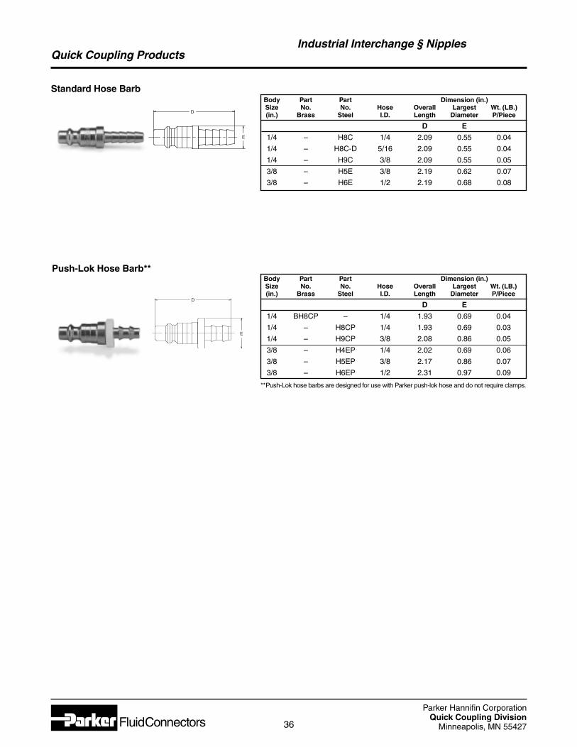
Parker Hannifin CorporationQuick Coupling Division
Minneapolis, MN 5542736
Quick Coupling ProductsIndustrial Interchange § Nipples
Standard Hose BarbBody Part Part Dimension (in.)Size No. No. Hose Overall Largest Wt. (LB.)(in.) Brass Steel I.D. Length Diameter P/Piece
D E
1/4 – H8C 1/4 2.09 0.55 0.04
1/4 – H8C-D 5/16 2.09 0.55 0.04
1/4 – H9C 3/8 2.09 0.55 0.05
3/8 – H5E 3/8 2.19 0.62 0.07
3/8 – H6E 1/2 2.19 0.68 0.08
Push-Lok Hose Barb**
D
E
D
E
Body Part Part Dimension (in.)Size No. No. Hose Overall Largest Wt. (LB.)(in.) Brass Steel I.D. Length Diameter P/Piece
D E
1/4 BH8CP – 1/4 1.93 0.69 0.04
1/4 – H8CP 1/4 1.93 0.69 0.03
1/4 – H9CP 3/8 2.08 0.86 0.05
3/8 – H4EP 1/4 2.02 0.69 0.06
3/8 – H5EP 3/8 2.17 0.86 0.07
3/8 – H6EP 1/2 2.31 0.97 0.09
**Push-Lok hose barbs are designed for use with Parker push-lok hose and do not require clamps.
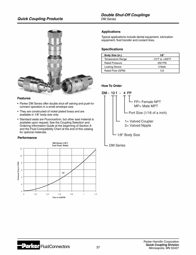
Parker Hannifin CorporationQuick Coupling Division
Minneapolis, MN 5542737
Quick Coupling Products
Features
• Parker DM Series offer double shut-off valving and push-to-connect operation in a small envelope size.
• They are constructed of nickel plated brass and areavailable in 1/8" body size only.
• Standard seals are Fluorocarbon, but other seal material isavailable upon request. See the Coupling Selection andOrdering Information Guide at the beginning of Section Aand the Fluid Compatibility Chart at the end of this catalogfor optional materials.
Double Shut-Off CouplingsDM Series
Performance
Applications
Typical applications include dental equipment, lubricationequipment, fluid transfer and coolant lines.
DM Series (1/8")Test Fluid: Water
0
2
4
6
8
10
12
0 0.2 0.4 0.6 0.8 1 1.2
Flow in USGPM
Pre
ssu
re D
rop
inP
SID
1/8"
How To Order
DM - 12 1 - 4
Port Size (1/16 of a inch)
1= Valved Coupler2= Valved Nipple
DM Series
1/8" Body Size
FP
FP= Female NPTMP= Male MPT
Specifications
Body Size (in.) 1/8"
Temperature Range -15°F to +400°F
Rated Pressure 250 PSI
Locking Device 5 Balls
Rated Flow (GPM) 0.8
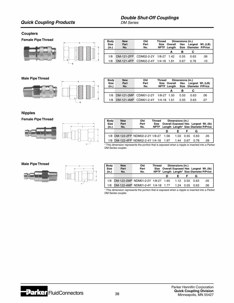
Parker Hannifin CorporationQuick Coupling Division
Minneapolis, MN 5542738
Quick Coupling ProductsDouble Shut-Off CouplingsDM Series
D
E
F
G
Nipples
Female Pipe Thread
A
C
B
Couplers
Female Pipe Thread
A
C
B
Male Pipe Thread
D
E
G
F
Male Pipe Thread
* This dimension represents the portion that is exposed when a nipple is inserted into a ParkerDM Series coupler.
Body New Old Thread Dimensions (in.)Size Part Part Size Overall Hex Largest Wt. (LB)(in.) No. No. NPTF Length Size Diameter P/Price
A B C
1/8 DM-121-2FP CDM02-2-2Y 1/8-27 1.42 0.55 0.63 .06
1/8 DM-121-4FP CDM02-2-4Y 1/4-18 1.81 0.67 0.78 .10
Body New Old Thread Dimensions (in.)Size Part Part Size Overall Hex Largest Wt. (LB)(in.) No. No. NPTF Length Size Diameter P/Price
A B C
1/8 DM-121-2MP CDM01-2-2Y 1/8-27 1.50 0.55 0.63 .06
1/8 DM-121-4MP CDM01-2-4Y 1/4-18 1.61 0.55 0.63 .07
Body New Old Thread Dimensions (in.)Size Part Part Size Overall Exposed Hex Largest Wt. (lb)(in.) No. No. NPTF Length Length* Size Diameter P/Price
D E F G
1/8 DM-122-2FP NDM02-2-2Y 1/8-27 1.56 1.03 0.55 0.63 .05
1/8 DM-122-4FP NDM02-2-4Y 1/4-18 1.97 1.44 0.67 0.78 .09
Body New Old Thread Dimensions (in.)Size Part Part Size Overall Exposed Hex Largest Wt. (lb)(in.) No. No. NPTF Length Length* Size Diameter P/Price
D E F G
1/8 DM-122-2MP NDM01-2-2Y 1/8-27 1.65 1.12 0.55 0.63 .05
1/8 DM-122-4MP NDM01-2-4Y 1/4-18 1.77 1.24 0.55 0.63 .06
* This dimension represents the portion that is exposed when a nipple is inserted into a ParkerDM Series coupler.

Parker Hannifin CorporationQuick Coupling Division
Minneapolis, MN 5542739
Appendices
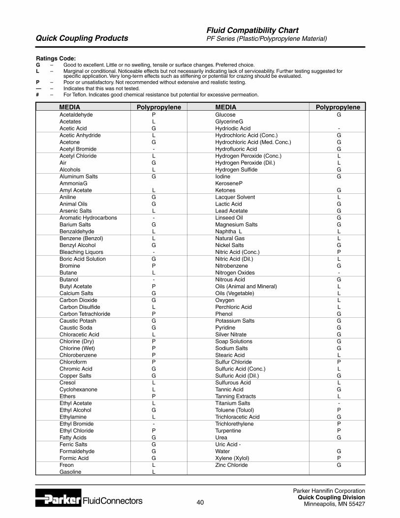
Parker Hannifin CorporationQuick Coupling Division
Minneapolis, MN 5542740
Quick Coupling Products
Ratings Code:G – Good to excellent. Little or no swelling, tensile or surface changes. Preferred choice.L – Marginal or conditional. Noticeable effects but not necessarily indicating lack of serviceability. Further testing suggested for
specific application. Very long-term effects such as stiffening or potential for crazing should be evaluated.P – Poor or unsatisfactory. Not recommended without extensive and realistic testing.— – Indicates that this was not tested.# – For Teflon. Indicates good chemical resistance but potential for excessive permeation.
MEDIA Polypropylene MEDIA Polypropylene
Fluid Compatibility ChartPF Series (Plastic/Polypropylene Material)
Acetaldehyde PAcetates LAcetic Acid GAcetic Anhydride LAcetone GAcetyl Bromide -Acetyl Chloride LAir GAlcohols LAluminum Salts GAmmoniaGAmyl Acetate LAniline GAnimal Oils GArsenic Salts LAromatic Hydrocarbons -Barium Salts GBenzaldehyde LBenzene (Benzol) LBenzyl Alcohol GBleaching Liquors -Boric Acid Solution GBromine PButane LButanol -Butyl Acetate PCalcium Salts GCarbon Dioxide GCarbon Disulfide LCarbon Tetrachloride PCaustic Potash GCaustic Soda GChloracetic Acid LChlorine (Dry) PChlorine (Wet) PChlorobenzene PChloroform PChromic Acid GCopper Salts GCresol LCyclohexanone LEthers PEthyl Acetate LEthyl Alcohol GEthylamine LEthyl Bromide -Ethyl Chloride PFatty Acids GFerric Salts GFormaldehyde GFormic Acid GFreon LGasoline L
Glucose GGlycerineGHydriodic Acid -Hydrochloric Acid (Conc.) GHydrochloric Acid (Med. Conc.) GHydrofluoric Acid GHydrogen Peroxide (Conc.) LHydrogen Peroxide (Dil.) LHydrogen Sulfide GIodine GKerosenePKetones GLacquer Solvent LLactic Acid GLead Acetate GLinseed Oil GMagnesium Salts GNaphtha L LNatural Gas LNickel Salts GNitric Acid (Conc.) PNitric Acid (Dil.) LNitrobenzene GNitrogen Oxides -Nitrous Acid GOils (Animal and Mineral) LOils (Vegetable) LOxygen LPerchloric Acid LPhenol GPotassium Salts GPyridine GSilver Nitrate GSoap Solutions GSodium Salts GStearic Acid LSulfur Chloride PSulfuric Acid (Conc.) LSulfuric Acid (Dil.) GSulfurous Acid LTannic Acid GTanning Extracts LTitanium Salts -Toluene (Toluol) PTrichloracetic Acid GTrichlorethylene PTurpentine PUrea GUric Acid -Water GXylene (Xylol) PZinc Chloride G
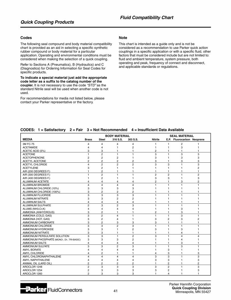
Parker Hannifin CorporationQuick Coupling Division
Minneapolis, MN 5542741
Quick Coupling ProductsFluid Compatibility Chart
CODES: 1 = Satisfactory 2 = Fair 3 = Not Recommended 4 = Insufficient Data Available
Codes
The following seal compound and body material compatibilitychart is provided as an aid in selecting a specific syntheticrubber compound or body material for a particularapplication. Operating and environmental conditions must beconsidered when making the selection of a quick coupling.
Refer to Sections A (Pneumatics), B (Hydraulics) and C(Diagnostics) for Ordering Information for Seal Codes forspecific products.
To indicate a special material just add the appropriatecode letter as a suffix to the catalog number of thecoupler. It is not necessary to use the code “STD” as thestandard Nitrile seal will be used when another code is notused.
For recommendations for media not listed below, pleasecontact your Parker representative or the factory.
Note
This chart is intended as a guide only and is not beconsidered as a recommendation to use Parker quick actioncouplings in a specific application or with a specific fluid, otherfactors that must be considered include but are not limited to:fluid and ambient temperature, system pressure, bothoperating and peak, frequency of connect and disconnect,and applicable standards or regulations.
BODY MATERIAL SEAL MATERIAL MEDIA Brass Steel 316 S.S. 303 S.S. Nitrile E.P. Fluorocarbon Neoprene
3M FC-75 4 4 4 4 1 1 2 1ACETAMIDE 4 4 1 2 1 1 3 1ACETIC ACID (5%) 3 3 1 1 2 1 1 1ACETONE 1 2 1 1 3 1 3 3ACETOPHENONE 2 2 2 1 3 1 3 3ACETYL ACETONE 2 2 2 2 3 1 3 3ACETYL CHLORIDE 4 2 2 2 3 3 1 3ACETYLENE 3 2 1 1 1 1 1 2AIR (200 DEGREES F.) 1 2 1 1 1 1 1 1AIR (300 DEGREES F.) 1 2 1 1 2 2 1 2AIR (400 DEGREES F.) 1 2 1 1 3 3 1 3ALUMINUM ACETATE 4 4 4 4 2 1 3 2ALUMINUM BROMIDE 4 4 4 4 1 1 1 1ALUMINUM CHLORIDE (10%) 3 3 3 3 1 1 1 1ALUMINUM CHLORIDE (100%) 3 2 2 2 1 1 1 1ALUMINUM FLUORIDE 3 3 3 3 1 1 1 1ALUMINUM NITRATE 3 3 2 2 1 1 1 1ALUMINUM SALTS 4 4 4 4 1 1 1 1ALUMINUM SULPHATE 2 3 2 3 1 1 1 1ALUMS (NH3,Cr,K) 4 4 4 4 1 1 3 1AMMONIA (ANHYDROUS) 3 2 1 1 2 1 3 1AMMONIA (COLD, GAS) 3 2 4 1 1 1 3 1AMMONIA (HOT, GAS) 3 2 4 1 3 2 3 2AMMONIUM CARBONATE 3 2 3 3 3 1 1 1AMMONIUM CHLORIDE 3 3 2 3 1 1 1 1AMMONIUM HYDROXIDE 3 3 1 2 3 1 3 1AMMONIUM NITRATE 3 3 1 1 1 1 4 1AMMONIUM PERSULFATE SOLUTION 3 3 1 2 3 1 4 4AMMONIUM PHOSPHATE (MONO-, DI-, TRI-BASIC) 3 3 3 2 1 1 4 1AMMONIUM SALTS 4 4 4 4 1 1 3 1AMMONIUM SULFATE 3 3 2 3 1 1 3 1AMYL BORATE 4 4 4 4 1 3 1 1AMYL CHLORIDE 4 2 1 1 4 3 1 3AMYL CHLORONAPHTHALENE 4 4 4 4 3 3 1 3AMYL NAPHTHALENE 4 4 4 4 3 3 1 3ANIMAL OIL (LARD OIL) 2 2 2 2 1 2 1 2AROCLOR 1248 2 3 3 3 3 2 1 3AROCLOR 1254 2 3 3 3 3 2 1 3AROCLOR 1260 2 3 3 3 1 4 1 1
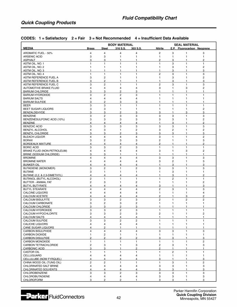
Parker Hannifin CorporationQuick Coupling Division
Minneapolis, MN 5542742
Quick Coupling Products
BODY MATERIAL SEAL MATERIAL MEDIA Brass Steel 316 S.S. 303 S.S. Nitrile E.P. Fluorocarbon Neoprene
AROMATIC FUEL - 50% 4 4 4 4 2 3 1 3ARSENIC ACID 3 3 1 1 1 1 1 1ASPHALT 3 3 1 1 2 3 1 2ASTM OIL, NO. 1 1 1 1 1 1 3 1 1ASTM OIL, NO. 2 1 1 1 1 1 3 1 2ASTM OIL, NO. 3 1 1 1 1 1 3 1 3ASTM OIL, NO. 4 1 1 1 1 2 3 1 3ASTM REFERENCE FUEL A 3 2 1 1 1 3 1 2ASTM REFERENCE FUEL B 3 2 1 1 1 3 1 3ASTM REFERENCE FUEL C 3 2 1 1 2 3 1 3AUTOMOTIVE BRAKE FLUID 4 4 4 4 3 1 3 2BARIUM CHLORIDE 3 3 2 3 1 1 1 1BARIUM HYDROXIDE 3 2 2 3 1 1 1 1BARIUM SALTS 4 4 4 4 1 1 1 1BARIUM SULFIDE 3 2 3 3 1 1 1 1BEER 3 3 1 1 1 1 1 1BEET SUGAR LIQUORS 3 3 1 1 1 1 1 2BENZALDEHYDE 3 3 2 3 3 1 3 3BENZENE 3 2 3 3 3 3 1 3BENZENESULFONIC ACID (10%) 3 3 3 3 3 3 1 2BENZINE 4 4 4 4 1 3 1 2BENZOIC ACID 3 3 3 3 3 3 1 3BENZYL ALCOHOL 4 3 1 2 3 2 1 2BENZYL CHLORIDE 3 3 2 3 3 3 1 3BLEACH LIQUOR 4 4 4 4 3 1 1 2BORAX 3 2 3 3 2 1 1 3BORDEAUX MIXTURE 4 4 4 4 2 1 1 2BORIC ACID 3 3 2 3 1 1 1 1BRAKE FLUID (NON-PETROLEUM) 4 4 4 4 3 1 3 2BRINE (SODIUM CHLORIDE) 3 3 1 1 1 1 1 1BROMINE 4 4 4 4 3 3 1 3BROMINE WATER 4 4 4 4 3 2 1 3BUNKER OIL 4 4 4 4 1 3 1 3BUTADIENE (MONOMER) 3 2 1 2 3 3 1 3BUTANE 3 1 1 1 1 3 1 1BUTANE (2,2, & 2,3-DIMETHYL) 4 4 4 4 1 3 1 2BUTANOL (BUTYL ALCOHOL) 2 1 1 1 1 2 1 1BUTTER - ANIMAL FAT 2 3 1 2 1 1 1 2BUTYL BUTYRATE 4 4 4 4 3 1 1 3BUTYL STEARATE 4 4 4 4 2 3 1 3CALCINE LIQUORS 4 4 4 4 1 1 1 4CALCIUM ACETATE 4 4 4 4 2 1 3 2CALCIUM BISULFITE 3 3 2 3 2 1 2 2CALCIUM CARBONATE 3 2 3 2 1 1 1 1CALCIUM CHLORIDE 3 3 2 3 1 1 1 1CALCIUM HYDROXIDE 3 3 2 3 1 1 1 1CALCIUM HYPOCHLORITE 3 3 2 3 2 1 1 2CALCIUM SALTS 4 4 4 4 1 1 1 1CALCIUM SULFIDE 3 3 2 2 1 1 1 1CALICHE LIQUORS 4 4 4 4 1 1 1 1CANE SUGAR LIQUORS 4 2 1 1 1 1 1 1CARBON BISULPHIDE 4 4 4 4 3 3 1 3CARBON DIOXIDE 1 2 1 1 1 1 1 1CARBON DISULFIDE 2 2 2 2 3 3 1 3CARBON MONOXIDE 1 1 1 1 1 1 1 2CARBON TETRACHLORIDE 2 3 1 3 2 3 1 3CARBONIC ACID 3 3 1 2 2 1 1 1CASTOR OIL 1 1 1 1 1 2 1 1CELLUGUARD 4 4 4 4 1 1 1 1CELLULUBE (NOW FYRQUEL) 4 4 4 4 3 1 1 3CHINA WOOD OIL (TUNG OIL) 2 2 1 1 1 3 1 2CHLORINATED SALT BRINE 4 4 4 4 3 3 1 3CHLORINATED SOLVENTS 4 4 4 4 3 3 1 3CHLOROBENZENE 3 3 2 3 3 3 1 3CHLOROBUTADIENE 4 4 4 4 3 3 1 3CHLOROFORM 3 2 2 1 3 3 1 3
Fluid Compatibility Chart
CODES: 1 = Satisfactory 2 = Fair 3 = Not Recommended 4 = Insufficient Data Available
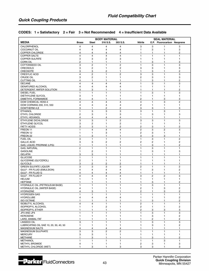
Parker Hannifin CorporationQuick Coupling Division
Minneapolis, MN 5542743
Quick Coupling Products
BODY MATERIAL SEAL MATERIAL MEDIA Brass Steel 316 S.S. 303 S.S. Nitrile E.P. Fluorocarbon Neoprene
CHLORPHENOL 4 4 4 4 3 3 1 3COCOANUT OIL 4 4 4 4 1 3 1 3COPPER CHLORIDE 4 4 4 4 1 1 1 2COPPER SALTS 4 4 4 4 1 1 1 1COPPER SULFATE 3 3 2 3 1 1 1 1CORN OIL 2 1 1 1 1 3 1 3COTTONSEED OIL 3 2 1 2 1 3 1 3CREOSOLS 3 2 1 2 3 3 1 3CREOSOTE 3 3 2 1 1 3 1 2CRESYLIC ACID 4 2 1 2 3 3 1 3CRUDE OIL 3 2 1 1 2 3 1 3CUTTING OIL 4 1 1 1 1 3 1 2DECANE 4 4 4 4 1 3 1 3DENATURED ALCOHOL 4 4 4 4 1 1 1 1DETERGENT, WATER SOLUTION 3 3 1 1 1 1 1 2DIESEL FUEL 1 1 1 1 1 3 1 3DIETHYLENE GLYCOL 3 1 1 1 1 1 1 1DIMETHYL FORMAMIDE 4 4 1 1 2 1 3 3DOW CHEMICAL HD50-4 4 4 4 4 4 1 3 2DOW CORNING 200, 510, 550 4 4 4 4 2 1 1 1DOWTHERM A,E 3 1 2 2 3 3 1 3ETHANOL 1 3 3 3 3 1 3 1ETHYL CHLORIDE 2 3 1 3 1 3 1 3ETHYL HEXANOL 4 4 4 4 1 1 1 1ETHYLENE DICHLORIDE 3 3 1 2 3 3 1 3ETHYLENE GLYCOL 3 2 1 2 1 1 1 1FATTY ACIDS 3 3 1 2 2 3 1 2FREON 11 1 4 4 4 2 3 2 3FREON 12 1 1 3 1 2 3 1 1FREON 22 1 3 1 1 3 3 3 1FUEL OIL 3 1 1 1 1 3 1 2GALLIC ACID 3 3 2 2 2 2 1 2GAS, LIQUID, PROPANE (LPG) 1 1 1 1 1 3 1 2GAS, NATURAL 2 1 1 1 1 3 1 1GASOLINE 1 2 1 1 1 3 1 3GELATIN 3 3 1 1 1 1 1 1GLUCOSE 1 1 1 1 1 1 1 1GLYCERINE (GLYCEROL) 2 1 1 1 1 1 1 1GLYCOLS 3 2 2 2 1 1 1 1GREEN SULFATE LIQUOR 3 3 3 3 2 1 1 2GULF - FR FLUID (EMULSION) 4 4 4 4 1 3 1 2GULF - FR FLUID G 4 4 4 4 1 1 1 1GULF - FR FLUID P 4 4 4 4 3 2 2 3HELIUM 1 1 1 1 1 1 1 1HEPTANE 1 1 1 1 1 3 1 2HYDRAULIC OIL (PETROLEUM BASE) 1 1 1 1 1 3 1 1HYDRAULIC OIL (WATER BASE) 4 1 1 1 2 1 3 2HYDRAZINE 4 3 1 1 2 1 3 2HYDROGEN GAS 1 1 1 1 1 1 1 1HYDROLUBE 4 4 4 4 1 1 1 2ISO OCTANE 1 1 1 1 1 3 1 2ISOBUTYL ALCOHOL 4 4 1 1 2 1 1 1ISOPROPYL ALCOHOL 1 1 2 1 2 1 1 2ISOPROPYL ETHER 1 1 1 1 2 3 3 3JP3 AND JP4 1 1 1 1 1 3 1 3KEROSENE 1 1 1 1 1 3 1 2LARD, ANIMAL FAT 1 1 1 1 1 2 1 2LINSEED OIL 3 1 1 1 1 3 1 3LUBRICATING OIL SAE 10, 20, 30, 40, 50 1 1 1 1 1 3 1 2MAGNESIUM SALTS 4 4 4 4 1 1 1 1MAGNESIUM SULPHATE 3 3 2 2 1 1 1 1MERCURY 3 3 1 1 1 1 1 1METHANE 1 3 1 1 1 3 1 2METHANOL 1 1 1 1 1 1 3 1METHYL BROMIDE 4 1 1 1 2 3 1 3METHYL CHLORIDE (WET) 1 3 1 3 3 3 1 3
Fluid Compatibility Chart
CODES: 1 = Satisfactory 2 = Fair 3 = Not Recommended 4 = Insufficient Data Available
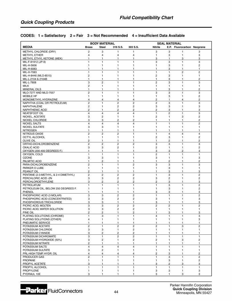
Parker Hannifin CorporationQuick Coupling Division
Minneapolis, MN 5542744
Quick Coupling ProductsFluid Compatibility Chart
BODY MATERIAL SEAL MATERIAL MEDIA Brass Steel 316 S.S. 303 S.S. Nitrile E.P. Fluorocarbon Neoprene
METHYL CHLORIDE (DRY) 2 3 1 1 3 3 1 3METHYL ETHER 4 4 4 4 1 3 1 3METHYL ETHYL KETONE (MEK) 1 1 1 1 3 1 3 3MIL-F-81912 (JP-9) 1 1 1 1 3 3 1 3MIL-H-5606 1 1 1 1 1 3 1 2MIL-H-6083 1 1 1 1 1 3 1 1MIL-H-7083 1 1 1 1 1 1 2 2MIL-H-8446 (MLO-8515) 2 1 1 1 2 3 1 1MIL-L-2104 & 2104B 1 1 1 1 1 3 1 2MIL-L-7808 3 2 1 1 2 3 1 3MILK 2 1 1 1 1 1 1 1MINERAL OILS 1 1 1 1 1 3 1 2MLO-7277 AND MLO-7557 2 1 1 1 3 3 1 3MOBILE HF 1 1 1 1 1 3 1 2MONOMETHYL HYDRAZINE 4 4 4 4 2 1 4 2NAPHTHA (COAL OR PETROLEUM) 2 1 2 2 2 3 1 3NAPHTHALENE 2 1 2 2 3 3 1 3NAPHTHENIC ACID 2 1 2 2 2 3 1 3NEATSFOOT OIL 4 4 4 4 1 2 1 3NICKEL, ACETATE 3 2 1 1 2 1 3 2NICKEL CHLORIDE 3 3 2 2 1 1 1 2NICKEL SALTS 4 4 4 4 1 1 1 2NICKEL SULFATE 3 3 1 1 1 1 1 1NITROGEN 1 1 1 1 1 1 1 1NITROUS OXIDE 2 2 2 1 1 4 4 4OCTYL ALCOHOL 1 1 1 1 2 3 1 2OLIVE OIL 2 1 1 1 1 2 1 2ORTHO-DICHLOROBENZENE 2 2 2 2 3 3 1 3OXALIC ACID 3 3 2 1 2 1 1 2OXYGEN (200-400 DEGREES F.) 1 1 1 1 3 3 2 3OXYGEN, COLD 1 1 1 1 2 1 1 1OZONE 3 3 1 1 3 1 1 3PALMITIC ACID 1 2 1 1 1 2 1 2PARA-DICHLOROBENZENE 2 1 1 2 3 3 1 3PARKER O LUBE 1 1 1 1 1 3 1 1PEANUT OIL 2 1 1 1 1 3 1 3PENTANE (2-3-METHYL, & 2-4 DIMETHYL) 2 2 2 2 1 3 1 2PERCHLORIC ACID -2N 3 3 2 2 3 2 1 2PERCHLOROETHYLENE 3 2 2 2 2 3 1 3PETROLATUM 1 1 1 1 1 3 1 2PETROLEUM OIL, BELOW 250 DEGREES F. 1 1 1 1 1 3 1 2PHENOL 1 1 1 1 3 3 1 3PHOSPHORIC ACID (3 MOLAR) 3 3 2 2 1 1 1 2PHOSPHORIC ACID (CONCENTRATED) 3 3 2 2 3 1 1 3PHOSPHOROUS TRICHLORIDE 3 3 1 1 3 1 1 3PICRIC ACID, MOLTEN 3 3 2 2 2 2 1 2PICRIC ACID, WATER SOLUTION 3 3 2 2 1 1 1 1PINE OIL 2 2 1 2 1 3 1 3PLATING SOLUTIONS (CHROME) 1 3 1 1 4 1 1 3PLATING SOLUTIONS (OTHER) 4 1 1 1 1 1 1 3PNEUMATIC SERVICE 1 1 1 1 1 1 1 1POTASSIUM ACETATE 2 1 2 2 2 1 3 2POTASSIUM CHLORIDE 3 3 1 2 1 1 1 1POTASSIUM CYANIDE 3 2 2 2 1 1 1 1POTASSIUM DICHROMATE 3 1 2 2 1 1 1 1POTASSIUM HYDROXIDE (50%) 3 2 1 2 2 1 3 2POTASSIUM NITRATE 2 1 1 1 1 1 1 1POTASSIUM SALTS 4 4 4 4 1 1 1 1POTASSIUM SULFATE 3 2 1 1 1 1 1 1PRL-HIGH TEMP. HYDR. OIL 4 4 4 4 2 3 1 2PRODUCER GAS 2 1 1 1 1 3 1 2PROPANE 1 1 1 1 1 3 1 2PROPYL ACETATE 3 1 1 1 3 2 3 3PROPYL ALCOHOL 1 1 1 1 1 1 1 1PROPYLENE 1 1 1 1 3 3 1 3PYDRAUL 10E 3 1 1 1 3 1 3 3
CODES: 1 = Satisfactory 2 = Fair 3 = Not Recommended 4 = Insufficient Data Available
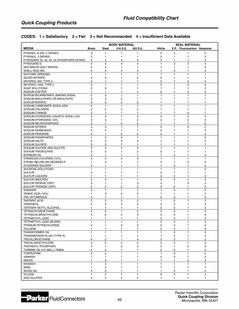
Parker Hannifin CorporationQuick Coupling Division
Minneapolis, MN 5542745
Quick Coupling ProductsFluid Compatibility Chart
CODES: 1 = Satisfactory 2 = Fair 3 = Not Recommended 4 = Insufficient Data Available
BODY MATERIAL SEAL MATERIAL MEDIA Brass Steel 316 S.S. 303 S.S. Nitrile E.P. Fluorocarbon Neoprene
PYDRAUL A-200, C SERIES 3 1 1 1 3 3 1 3PYDRAUL, 3 SERIES 3 1 1 1 3 1 1 3PYROGARD 42, 43, 53, 55 (PHOSPHATE ESTER) 4 4 4 4 3 1 1 3PYROGARD D 4 4 4 4 1 3 3 2SEA WATER (SALT WATER) 2 3 1 1 1 1 1 2SHELL IRUS 905 4 4 4 4 1 3 1 2SILICONE GREASES 1 1 1 1 1 1 1 1SILVER NITRATE 3 3 1 2 2 1 1 1SKYDROL 500, TYPE 2 3 1 1 1 3 1 3 3SKYDROL 7000, TYPE 2 3 1 1 1 3 1 2 3SOAP SOLUTIONS 3 3 1 1 1 1 1 2SODIUM ACETATE 1 1 1 1 2 1 3 2SODIUM BICARBONATE (BAKING SODA) 2 2 1 1 1 1 1 1SODIUM BISULPHATE OR BISULPHITE 3 3 2 1 1 1 1 1SODIUM BORATE 3 2 2 2 1 1 1 1SODIUM CARBONATE (SODA ASH) 4 1 1 1 1 1 1 1SODIUM CHLORIDE 3 2 2 2 1 1 1 1SODIUM CYANIDE 3 1 1 1 1 1 4 1SODIUM HYDROXIDE (CAUSTIC SODA, LYE) 3 2 1 2 2 1 2 2SODIUM HYDROXIDE, 50% 3 3 1 2 2 1 2 2SODIUM METAPHOSPHATE 2 1 2 2 1 1 1 2SODIUM NITRATE 3 2 1 1 2 1 4 2SODIUM PERBORATE 3 3 1 1 2 1 1 2SODIUM PEROXIDE 3 1 2 2 2 1 1 2SODIUM PHOSPHATES 1 3 2 1 1 1 1 2SODIUM SALTS 4 4 4 4 1 1 1 2SODIUM SULFATE 3 2 1 1 1 1 1 1SODIUM SULFIDE AND SULFITE 3 3 2 3 1 1 1 1SODIUM THIOSULFATE 3 3 1 2 2 1 1 1SOYBEAN OIL 2 1 1 1 1 3 1 3STANNOUS CHLORIDE (15%) 3 3 2 3 1 1 1 1STEAM, BELOW 400 DEGEEES F. 1 3 1 1 3 1 3 3STODDARD SOLVENT 2 1 1 1 1 3 1 2SUCROSE SOLUTIONS 1 1 1 1 1 1 1 2SULFUR 2 1 1 1 3 1 1 1SULFUR LIQUORS 1 1 1 1 2 2 1 2SULFUR (MOLTEN) 3 3 1 1 3 3 1 3SULFUR DIOXIDE (DRY) 3 1 1 3 3 1 3 3SULFUR TRIOXIDE (DRY) 2 2 2 3 3 2 1 3SUNSAFE 3 1 1 1 1 3 1 2TANNIC ACID (10%) 1 3 2 3 1 1 1 2TAR, BITUMINOUS 2 1 1 1 2 3 1 3TARTARIC ACID 2 3 3 2 1 2 1 2TERPINEOL 4 4 4 4 2 3 1 3TERTIARY BUTYL ALCOHOL 1 1 1 1 2 2 1 2TETRACHLOROETHANE 4 2 1 2 3 3 1 3TETRACHLOROETHYLENE 3 2 2 4 3 3 1 3TETRAETHYL LEAD 1 1 1 1 2 3 1 2TETRAETHYL LEAD (BLEND) 1 1 1 1 2 3 1 3TITANIUM TETRACHLORIDE 2 1 2 3 2 3 1 3TOLUENE 1 1 1 1 3 3 1 3TRANSFORMER OIL 1 1 1 1 1 3 1 2TRANSMISSION FLUID (TYPE A) 1 1 1 1 1 3 1 2TRICHLOROETHANE 4 2 1 4 3 3 1 3TRICHLOROETHYLENE 3 2 2 2 3 3 1 3TRICRESYL PHOSPHATE 4 1 2 2 3 1 2 3TURBINE OIL #15 (MIL-L-7808A) 4 2 1 1 2 3 1 3TURPENTINE 3 2 1 1 1 3 1 3VARNISH 1 1 1 1 2 3 1 3WATER 1 3 1 1 1 1 2 2WHISKEY 1 3 1 1 1 1 1 1WINE 1 3 1 1 1 1 1 1WOOD OIL 4 2 1 1 1 3 1 2XYLENE 1 2 1 1 3 3 1 3ZINC SULFATE 3 3 2 2 1 1 1 1
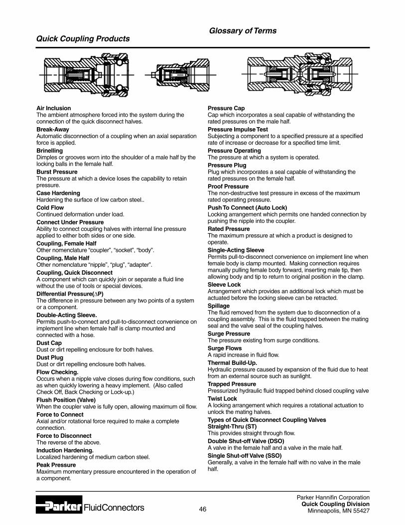
Parker Hannifin CorporationQuick Coupling Division
Minneapolis, MN 5542746
Quick Coupling ProductsGlossary of Terms
Air InclusionThe ambient atmosphere forced into the system during theconnection of the quick disconnect halves.Break-AwayAutomatic disconnection of a coupling when an axial separationforce is applied.BrinellingDimples or grooves worn into the shoulder of a male half by thelocking balls in the female half.Burst PressureThe pressure at which a device loses the capability to retainpressure.Case HardeningHardening the surface of low carbon steel..Cold FlowContinued deformation under load.Connect Under PressureAbility to connect coupling halves with internal line pressureapplied to either both sides or one side.Coupling, Female HalfOther nomenclature “coupler”, “socket”, “body”.Coupling, Male HalfOther nomenclature “nipple”, “plug”, “adapter”.Coupling, Quick DisconnectA component which can quickly join or separate a fluid linewithout the use of tools or special devices.Differential Pressure(∆P)The difference in pressure between any two points of a systemor a component.Double-Acting Sleeve.Permits push-to-connect and pull-to-disconnect convenience onimplement line when female half is clamp mounted andconnected with a hose.Dust CapDust or dirt repelling enclosure for both halves.Dust PlugDust or dirt repelling enclosure both halves.Flow Checking.Occurs when a nipple valve closes during flow conditions, suchas when quickly lowering a heavy implement. (Also calledCheck Off, Back Checking or Lock-up.)Flush Position (Valve)When the coupler valve is fully open, allowing maximum oil flow.Force to ConnectAxial and/or rotational force required to make a completeconnection.Force to DisconnectThe reverse of the above.Induction Hardening.Localized hardening of medium carbon steel.Peak PressureMaximum momentary pressure encountered in the operation ofa component.
Pressure CapCap which incorporates a seal capable of withstanding therated pressures on the male half.Pressure Impulse TestSubjecting a component to a specified pressure at a specifiedrate of increase or decrease for a specified time limit.Pressure OperatingThe pressure at which a system is operated.Pressure PlugPlug which incorporates a seal capable of withstanding therated pressures on the female half.Proof PressureThe non-destructive test pressure in excess of the maximumrated operating pressure.Push To Connect (Auto Lock)Locking arrangement which permits one handed connection bypushing the nipple into the coupler.Rated PressureThe maximum pressure at which a product is designed tooperate.Single-Acting SleevePermits pull-to-disconnect convenience on implement line whenfemale body is clamp mounted. Making connection requiresmanually pulling female body forward, inserting male tip, thenallowing body and tip to return to original position in the clamp.Sleeve LockArrangement which provides an additional lock which must beactuated before the locking sleeve can be retracted.SpillageThe fluid removed from the system due to disconnection of acoupling assembly. This is the fluid trapped between the matingseal and the valve seal of the coupling halves.Surge PressureThe pressure existing from surge conditions.Surge FlowsA rapid increase in fluid flow.Thermal Build-Up.Hydraulic pressure caused by expansion of the fluid due to heatfrom an external source such as sunlight.Trapped PressurePressurized hydraulic fluid trapped behind closed coupling valveTwist LockA locking arrangement which requires a rotational actuation tounlock the mating halves.Types of Quick Disconnect Coupling ValvesStraight-Thru (ST)This provides straight through flow.Double Shut-off Valve (DSO)A valve in the female half and a valve in the male half.Single Shut-off Valve (SSO)Generally, a valve in the female half with no valve in the malehalf.
Parker Hannifin CorporationQuick Coupling Division
Minneapolis, MN 5542747
Quick Coupling Products
SAFETY GUIDE FOR SELECTING AND USING QUICK ACTIONCOUPLINGS AND RELATED ACCESSORIES
DANGER: Failure or improper selection or improper use of quick action couplings or related accessories can cause death, personalinjury and property damage. Possible consequences of failure or improper selection or improper use of quick action couplingsor related accessories include but are not limited to:
• Couplings or parts thrown off at high speed. • Dangerously whipping hose.• High velocity fluid discharge. • Contact with conveyed fluids that may be hot, cold,• Explosion or burning of the conveyed fluid. • toxic, or otherwise injurious.• Contact with suddenly moving or falling objects that are • Sparking or explosion while paint or flammable• to be held in position or moved by the conveyed fluid. • liquid spraying.
Before selecting or using any Parker quick action couplings or related accessories, it is important that you read and follow thefollowing instructions.
Safety Guide
1.1 Scope: This safety guide provides instructions for selecting and using(including installing connecting, disconnecting, and maintaining) quick actioncouplings and related accessories (including caps, plugs, blow guns, and twoway valves). This safety guide is a supplement to and is to be used with, thespecific Parker publications for the specific quick action couplings and relatedaccessories that are being considered for use.
1.2 Fail-Safe: Quick action couplings or the hose they are attached to can failwithout warning for many reasons. Design all systems and equipment in a fail-safe mode, so that failure of the quick action coupling or hose will not endangerpersons or property.
1.3 Distribution: Provide a copy of this safety guide to each person that isresponsible for selecting or using quick action coupling products. Do not selector use quick action couplings without thoroughly reading and understandingthis safety guide as well as the specific Parker publications for the productsconsidered or selected.
1.4 User Responsibility: Due to the wide variety of operating conditions anduses for quick action couplings, Parker and its distributors do not represent orwarrant that any particular quick action coupling is suitable for any specific enduse system. This safety guide does not analyze all technical parameters thatmust be considered in selecting a product. The user, through its own analysisand testing, is solely responsible for:
• Making the final selection of the quick action couplings.• Assuring that the user’s requirements are met and that the use presents nohealth or safety hazards.• Providing all appropriate health and safety warnings on the equipment onwhich the quick action couplings are used.
1.5 Additional Questions: Call the appropriate Parker customer servicedepartment if you have any questions or require any additional information. Forthe telephone numbers of the appropriate customer service department, seethe Parker publication for the product being considered or used.
2.0 QUICK ACTION COUPLING SELECTION INSTRUCTIONS
2.1 Pressure: Quick action couplings selection must be made so that thepublished rated pressure of the coupling is equal to or greater than themaximum system pressure. Surge pressures in the system higher than therated pressure of the coupling will shorten the quick action coupling’s life. Donot confuse burst pressure or other pressure values with rated pressure anddo not use burst pressure or other pressure values for this purpose.
2.2 Fluid Compatibility: Quick action couplings selection must assurecompatibility of the body and seal materials with the fluid media used. See thefluid compatibility chart in the Parker publication for the product beingconsidered or used.
2.3 Temperature: Be certain that fluid and ambient temperatures, bothsteady and transient, do not exceed the limitations of the quick actioncouplings. Use caution and hand protection when connecting or disconnectingquick action couplings that are heated or cooled by the media they areconducting or by their environment.
2.4 Size: Transmission of power by means of pressurized liquid varies withpressure and rate of flow. The size of the quick action couplings and othercomponents of the system must be adequate to keep pressure losses to aminimum and avoid damage due to heat generation or excessive fluid velocity.
2.5 Pressurized Connect or Disconnect: If connecting or disconnectingunder pressure is a requirement, use only quick action couplings designed forthat purpose. The rated operating pressure of a quick action coupling may notbe the pressure at which it may be safely connected or disconnected.
2.6 Environment: Care must be taken to ensure that quick action couplingsare either compatible with or protected from the environment (that is,surrounding conditions) to which they are exposed. Environmental conditionsincluding but not limited to ultraviolet radiation, ozone, moisture, water, saltwater, chemicals, and air pollutants can cause degradation and prematurefailure.
2.7 Locking Means: Ball locking quick action couplings can unintentionallydisconnect if they are dragged over obstructions on the end of a hose or if thesleeve is bumped or moved enough to cause disconnect. Sleeves designedwith flanges to provide better gripping for oily or gloved hands are especiallysusceptible to accidental disconnect and should not be used where theseconditions exist. Sleeve lock or union (threaded) sleeve designs should beconsidered where there is a potential for accidental uncoupling.
2.8 Mechanical Loads: External forces can significantly reduce quick actioncouplings’ life or cause failure. Mechanical loads which must be consideredinclude excessive tensile or side loads, and vibration. Unusual applicationsmay require special testing prior to quick action couplings selection.
2.9 Specifications and Standards: When selecting quick action couplings,government, industry, and Parker specifications must be reviewed and followedas applicable.
2.10 Vacuum: Not all quick action couplings are suitable or recommended forvacuum service. Quick action couplings used for vacuum applications must beselected to ensure that the quick actions couplings will withstand the vacuumand pressure of the system.
2.11 Fire Resistant Fluids: Some fire resistant fluids require seals other thanthe standard nitrile used in many quick action couplings.
2.12 Radiant Heat: Quick action couplings can be heated to destruction orloss of sealability without contact by such nearby items as hot manifolds ormolten metal. The same heat source may then initiate a fire. This can occurdespite the presence of cool air around the quick action couplings.
2.13 Welding and Brazing: Heating of plated parts, including quick actioncouplings and port adapters, above 450°F (232°C) such as during welding,brazing, or soldering may emit deadly gases and may cause coupling sealdamage.
Safety Guide
3.0 QUICK ACTION COUPLING INSTALLATION INSTRUCTIONS
3.1 Pre-Installation Inspection: Before installing a quick action coupling,visually inspect it and check for correct style, body material, seal material, andcatalog number. Before final installation, coupling halves should be connectedand disconnected with a sample of the mating half with which they will beused.
3.2 Quick Action Coupling Halves From Other Manufacturers: If a quickaction coupling assembly is made up of one Parker half and one half fromanother manufacturer, the lowest pressure rating of the two halves should notbe exceeded.
3.3 Fitting Installation: Use a thread sealant, lubricant, or a combination ofboth when assembling pipe thread joints in quick action couplings. Be sure thesealant is compatible with the system fluid or gas. To avoid systemcontamination, use a liquid or paste type sealant rather than a tape style. Usethe flats provided to hold the quick action coupling when installing fittings. Donot use pipe wrenches or a vice on other parts of the coupling to hold it wheninstalling or removing fittings as damage or loosening of threaded joints in thecoupling assembly could result. Do not apply excessive torque to taper pipethreads because cracking or splitting of the female component can result.
3.4 Caps and Plugs: Use dust caps and plugs when quick action couplingsare not coupled to exclude dirt and contamination and to protect criticalsurfaces from damage.
3.5 Coupling Location: Locate quick action couplings where they can bereached for connect or disconnect without exposing the operator to slipping,falling, getting sprayed, or coming in contact with hot or moving parts.
3.6 Hose Whips: Use a hose whip (a short length of hose between the tooland the coupling half) instead of rigidly mounting a coupling half on hand toolsor other devices. This reduces the potential for coupling damage if the tool isdropped and provides some isolation from mechanical vibration which couldcause uncoupling.
4.0 QUICK ACTION COUPLING MAINTENANCE INSTRUCTIONS
4.1 Even with proper selection and installation, quick action coupling life maybe significantly reduced without a continuing maintenance program. Frequencyshould be determined by the severity of the application and risk potential. Amaintenance program must be established and followed by the user and mustinclude the following as a minimum:
4.2 Visual Inspection of Quick Action Couplings: Any of the followingconditions require immediate shut down and replacement of the quick actioncoupling:
• Cracked, damaged, or corroded quick action coupling parts.• Leaks at the fitting, valve or mating seal.• Broken coupling mounting hardware, especially breakaway clamps.
4.3 Visual Inspection All Other: The following items must be tightened,repaired or replaced as required:
• Leaking seals or port connections.• Remove excess dirt buildup on the coupling locking means
or on the interface area of either coupling half.• Clamps, guards, and shields.• System fluid level, fluid type and any air entrapment.
4.4 Functional Test: Operate the system at maximum operating pressureand check for possible malfunctions and freedom from leaks. Personnel mustavoid potential hazardous areas while testing and using the system.
4.5 Replacement Intervals: Specific replacement intervals must beconsidered based on previous service life, government or industryrecommendations, or when failures could result in unacceptable downtime,damage or injury risk. See instruction 1.2 above.
Additional copies of the preceding safety information can be ordered byrequesting “Safety Guide For Selecting and Using Quick Action Couplings andRelated Accessories,” Parker Publication No. 3800-B1.0
Contact The Quick Coupling Division, Minneapolis, MN.
Quick Coupling Products
48
Parker Hannifin CorporationQuick Coupling Division
Minneapolis, MN 55427
FAILURE OR IMPROPER SELECTION OR IMPROPER USE OF THE PRODUCTS AND/OR SYSTEMS DESCRIBED HEREIN OR RELATED ITEMS CAN CAUSE DEATH, PERSONALINJURY AND PROPERTY DAMAGE.
This document and other information from Parker Hannifin Corporation, it's subsidiaries and authorized distributors provide product and/or system options for further investigation byusers having technical expertise. It is important that you analyze all aspects of your application and review the information concerning the product or system in the current product catalog.Due to the variety of operating conditions and applications for these products or systems, the user, through its own analysis and testing, is solely responsible for making the final selectionof the products and systems and assuring that all performance, safety and warning requirements of the application are met.
The products described herein, including without limitation, product features, specifications, designs, availability and pricing, are subject to change by Parker Hannifin Corporation and itssubsidiaries at any time without notice.
Offer of SaleThe items described in this document are hereby offered for sale by Parker Hannifin Corporation, its subsidiaries or its authorized distributors. This offer and its acceptance are governedby the provisions stated in the “Offer of Sale.”
Quick Coupling Division8145 Lewis Road
Minneapolis, MN 55427
© 2006, Revised January 2006, Parker Hannifin Corporation, All Rights Reserved.
Quick Coupling Products
Note: Flow charts in this catalog reflect actual test data. Flow tests were conducted using ANSI standard test procedures.
Introduction
The Parker Hannifin Quick Coupling Division offers a fullrange of precision quick action couplings for use in the pro-cess, power and instrumentation fields.
Quick couplings are used to quickly and easily connect anddisconnect rigid or flexible tubing to hose or pipe–without theuse of tools. They are available in straight-through (no valv-ing), single shut-off (valving in the coupler half only), and dou-ble shut-off (valving in both the coupler and nipple halves)configurations for maximum flexibility. With sealing integrity to1 x 10-6 cc/sec of helium at 50 millitor, Parker Quick Couplingsare ideal for use with a wide range of media in vacuum orhigh pressure applications.
Available end configurations include: Male and Female PipeThread, A-LOK® and CPI tube ends, 37° Flare, Hose Barb,and Bulkhead fittings. Stainless Steel couplings featureFluorocarbon seals as standard. Brass Couplings areequipped with Nitrile seals. Ethylene Propylene,Perfluoroelastomer, and other seal materials are also avail-able upon request.
Consult the Safety Guide in the back of this catalog for moreinformation on the selection and use of quick action cou-plings.
Parker Quick couplings designed for instrumentation applica-tions are built to stringent standards and meticulously testedfor sealing integrity. Applications for these precision couplingsinclude, but are not limited to the following:
• All types of instruments
• Laboratory equipment
• Vacuum systems
• Chemical research
• Gas supply systems
• Portable analyzers
• Control panels
• Hydraulic and pneumatic systems
• Medical equipment
• Food processing equipment
• Calibration systems
• Test stands
• Gas chromatographs
• Micro-contamination devices
Introduction
Parker Hannifin CorporationQuick Coupling Division
Minneapolis, MN 5542749
Quick Coupling ProductsOffer of Sale
The items described in this document are hereby offered for sale at prices to be established by Parker Hannifin Corporation, its subsidiaries and itsauthorized distributors.This offer and its acceptance by any customer (“Buyer”) shall be governed by all of the following Terms and Conditions. Buyer’sorder for any item described in its document, when communicated to Parker Hannifin Corporation, its subsidiary or an authorized distributor (“Seller”)verbally or in writing, shall constitute acceptance of this offer.
1. Terms and Conditions of Sale: All descriptions, quotations, proposals, offers,acknowledgments, acceptances and sales of Seller’s products are subject to andshall be governed exclusively by the terms and conditions stated herein. Buyer’sacceptance of any offer to sell is limited to these terms and conditions. Any terms orconditions in addition to, or inconsistent with those stated herein, proposed byBuyer in any acceptance of an offer by Seller, are hereby objected to. No such addi-tional, different or inconsistent terms and conditions shall become part of the con-tract between Buyer and Seller unless expressly accepted in writing by Seller.Seller’s acceptance of any offer to purchase by Buyer is expressly conditional uponBuyer’s assent to all the terms and conditions stated herein, including any terms inaddition to, or inconsistent with those contained in Buyer’s offer. Acceptance ofSeller’s products shall in all events constitute such assent.
2. Payment: Payment shall be made by Buyer net 30 days from the date of deliv-ery of the items purchased hereunder. Amounts not timely paid shall bear interestof 1% for each month or a portion thereof that Buyer is late in making payment.Any claims by Buyer for omissions or shortages in a shipment shall be waivedunless Seller receives notice thereof within 30 days after Buyer’s receipt of the ship-ment.
3. Delivery: Unless otherwise provided on the face hereof, delivery shall be madeF.O.B. Seller’s plant. Regardless of the method of delivery, however, risk of lossshall pass to Buyer upon Seller’s delivery to a carrier. Any delivery dates shown areapproximate only and Seller shall have no liability for any delays in delivery.
4. Warranty: Seller warrants that the items sold hereunder shall be free fromdefects in material or workmanship for a period of 365 days from the date of ship-ment to Buyer. THIS WARRANTY COMPRISES THE SOLE AND ENTIRE WAR-RANTY PERTAINING TO ITEMS PROVIDED HEREUNDER. SELLER MAKESNO OTHER WARRANTY, GUARANTEE, OR REPRESENTATION OF ANY KINDWHATSOEVER. ALL OTHER WARRANTIES, INCLUDING BUT NOT LIMITEDTO, MERCHANTIBILITY AND FITNESS FOR PURPOSE,WHETHER EXPRESS,IMPLIED, OR ARISING BY OPERATION OF LAW,TRADE USAGE, OR COURSEOF DEALING ARE HEREBY DISCLAIMED.
NOTWITHSTANDING THE FOREGOING,THERE ARE NO WARRANTIES WHAT-SOEVER ON ITEMS BUILT OR ACQUIRED WHOLLY OR PARTIALLY,TOBUYER’S DESIGNS OR SPECIFICATIONS.
5. Limitation Of Remedy: SELLER’S LIABILITY ARISING FROM OR IN ANYWAY CONNECTED WITH THE ITEMS SOLD OR THIS CONTRACT SHALL BELIMITED EXCLUSIVELY TO REPAIR OR REPLACEMENT OF THE ITEMSSOLD OR REFUND OF THE PURCHASE PRICE PAID BY BUYER, AT SELL-ER’S SOLE OPTION. IN NO EVENT SHALL SELLER BE LIABLE FOR ANYINCIDENTAL, CONSEQUENTIAL OR SPECIAL DAMAGES OF ANY KIND ORNATURE WHATSOEVER, INCLUDING BUT NOT LIMITED TO LOST PROFITSARISING FROM OR IN ANY WAY CONNECTED WITH THIS AGREEMENT ORITEMS SOLD HEREUNDER,WHETHER ALLEDGED TO ARISE FROM BREACHOF CONTRACT, EXPRESS OR IMPLIED WARRANTY, OR IN TORT, INCLUDINGWITHOUT LIMITATION, NEGLIGENCE, FAILURE TO WARN OR STRICT LIABIL-ITY.
6. Changes, Reschedules and Cancellations: Buyer may request to modify thedesigns or specifications for the items sold hereunder as well as the quantities anddelivery dates thereof, or may request to cancel all or part of this order, however, nosuch requested modification or cancellation shall become part of the contractbetween Buyer and Seller unless accepted by Seller in a written amendment to thisAgreement. Acceptance of any such requested modification or cancellation shall beat Seller’s discretion, and shall be upon such terms and conditions as Seller mayrequire.
7. Special Tooling: A tooling charge may be imposed for any special tooling,including without limitation, dies, fixtures, molds and patterns, acquired to manufac-ture items sold pursuant to this contract. Such special tooling shall be and remainSeller’s property notwithstanding payment of any charges therefore by Buyer. In noevent will Buyer acquire any interest in apparatus belonging to Seller which is uti-lized in the manufacture of the items sold hereunder, even if such apparatus hasbeen specially converted or adapted for such manufacture and notwithstanding anycharges paid by Buyer therefore. Unless otherwise agreed, Seller shall have theright to alter, discard or otherwise dispose of any special tooling or other property inits sole discretion at any time.
8. Buyer’s Property: Any designs, tools, patterns, materials, drawings, confiden-tial information or equipment furnished by the Buyer or any other items whichbecome Buyer’s property, may be considered obsolete and may be destroyed bySeller after two (2) consecutive years have elapsed without Buyer placing an orderfor the items which are manufactured using such property. Seller shall not beresponsible for any loss or damage to such property while it is in Seller’s posses-sion or control.
9. Taxes: Unless otherwise indicated on the face hereof, all prices and charges areexclusive of excise, sales, use, property, occupational or like taxes which may beimposed by any taxing authority upon the manufacture, sale or delivery of the itemssold hereunder. If any such taxes must be paid by Seller or if Seller is liable for thecollection of such tax, the amount thereof shall be in addition to the amounts for theitems sold. Buyer agrees to pay all such taxes or to reimburse Seller therefore uponreceipt of its invoice. If Buyer claims exemption from any sales, use or other taximposed by any taxing authority, Buyer shall save Seller harmless from and againstany such tax, together with any interest or penalties thereon which may beassessed if the items are held to be taxable.
10. Indemnity For Infringement of Intellectual Property Rights: Seller shallhave no liability for infringement of any patents, trademarks, copyrights, tradedress, trade secrets or similar rights except as provided in this Part 10. Seller willdefend and indemnify Buyer against allegations of infringement of U.S. patents.U.S. trademarks, copyrights, trade dress and trade secrets (hereinafter ‘IntellectualProperty Rights’). Seller will defend at its expense and will pay the cost of any set-tlement or damages awarded in an action brought against Buyer based on an alle-gation that an item sold pursuant to this contract infringes the Intellectual PropertyRights of a third party. Seller’s obligation to defend and indemnify Buyer is contin-gent on Buyer notifying Seller within ten (10) days after Buyer becomes aware ofsuch allegations of infringement, and Seller having sole control over the defense ofany allegations or actions including all negotiations for settlement or compromise. Ifan item sold hereunder is subject to a claim that it infringes the Intellectual PropertyRights of a third party, Seller may, at its sole expense and option, procure for Buyerthe right to continue using said item, replace or modify said item so as to make itnoninfringing, or offer to accept return of said item and return the purchase priceless a reasonable allowance for depreciation. Notwithstanding the foregoing, Sellershall have no liability for claims of infringement based on information provided byBuyer, or directed to items delivered hereunder for which the designs are specifiedin whole or part by Buyer, or infringements resulting from the modification, combi-nation or use in a system of any item sold hereunder. The foregoing provisions ofthis Part 10 shall constitute Seller’s sole and exclusive liability and Buyer’s sole andexclusive remedy for infringement of Intellectual Property rights.
If a claim is based on information provided by Buyer or if the design for an itemdelivered hereunder is specified in whole or in part by Buyer, Buyer shall defendand indemnify Seller for all costs, expenses or judgments resulting from any claimthat such item infringes any patent, trademark, copyright, trade dress, trade secretor any similar right.
11. Force Majeure: Seller does not assume the risk of and shall not be liable fordelay or failure to perform any of Seller’s obligations by reason of circumstancesbeyond the reasonable control of Seller (hereinafter ‘Events of Force Majeure’).Events of Force Majeure shall include without limitation, accidents, acts of God,strikes or labor disputes, acts, laws, rules or regulations of any government or gov-ernment agency, fires, floods, delays or failures in delivery of carriers or suppliers,shortages of materials and any other cause beyond Seller’s control.
12. Entire Agreement/Governing Law: The terms and conditions set forth herein,together with any amendments, modifications and any different terms or conditionsexpressly accepted by Seller in writing, shall constitute the entire Agreement con-cerning the items sold, and there are no oral or other representations or agree-ments which pertain thereto. This Agreement shall be governed in all respects bythe law of the State of Ohio. No actions arising out of the sale of the items soldhereunder or this Agreement may be brought by either party more than two (2)years after the cause of action accrues.
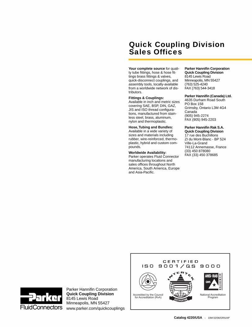
InstrumentationQuick CouplingProducts
The World Standard
Catalog 4220/USAFebruary 2006
Parker Hannifin CorporationQuick Coupling Division8145 Lewis RoadMinneapolis, MN 55427www.parker.com/quickcouplings
Catalog 4220/USA - 10M 02/06/GRA/AP
Your complete source for quali-ty tube fittings, hose & hose fit-tings brass fittings & valves,quick-disconnect couplings, andassembly tools, locally-availablefrom a worldwide network of dis-tributors.
Fittings & Couplings:Available in inch and metric sizescovering SAE, BSP, DIN, GAZ,JIS and ISO thread configura-tions, manufactured from stain-less steel, brass, aluminum,nylon and thermoplastic.
Hose,Tubing and Bundles:Available in a wide variety ofsizes and materials includingrubber, wire-reinforced, thermo-plastic, hybrid and custom com-pounds.
Worldwide Availability:Parker operates Fluid Connectormanufacturing locations andsales offices throughout NorthAmerica, South America, Europeand Asia-Pacific.
Parker Hannifin CorporationQuick Coupling Division8145 Lewis RoadMinneapolis, MN 55427(763) 525-4240FAX (763) 544-3418
Parker Hannifin (Canada) Ltd.4635 Durham Road SouthPO Box 158Grimsby, Ontario L3M 4G4Canada(905) 945-2274FAX (905) 945-2203
Parker Hannifin Rak S.A.Quick Coupling Division17 rue des BuchillonsZI du Mont-Blanc - BP 524Ville-La-Grand74112 Annemasse, France(33) 450 878080FAX (33) 450 378685
Quick Coupling Division Sales Offices