Embed Size (px)
Citation preview

Section III Covered and Insulated Wire and Cable
Chapter 8
Insulation and Related Cable Components
This chapter describes in further detail the insulation and coverings mentioned previously and also describes the jackets shields sheaths and other materials used in the assembly of a cable An explanation of some of the dielecshytric terms is in Appendix 8A
Standards are specifications for cable insulation and coverings are developed and set forth in the publications of ASTM Underwriters Laboratories Inc (UL) and Insulated Cable Engineers Association (ICEA) and othmiddot ers This chapter provides summary data and the reader is advised to consult the referenced standards for further detail
Selection of insulating and other materials that surshyround the conductors is based on a number of performance factors
1 Electrical Dielectric constant insulation power factor insulation resistance (ac and I-minute de) chargshying current arc resistance tracking susceptibility ozone resistance Uniformity of potential gradient is influenced by shielding Requirements in this category depend conshysiderably on voltage
2 Mechanical Toughness and flexibility tensile comshypressive and impact strengths resistance to abrasion crushing and moisture brittleness
3 Thermal Softening or flow temperature expansion and contraction compatibility with ambient operating emergency overload and short-circuit conductor temperatures
4 Chemical Stability of materials on exposure to oils Bame ozone suulight acids and alkalies moisture absorption
5 Code Requirements Installation of cable in accormiddot dance with NEe and under the jurisdiction of separate electrical inspection authorities usually requires cable labeled by Underwriters Laboratories (UL)
Typical 3-Conductor Cable Assemblies The arrangement of layers of insulating and other ma~
terials around the bare conductors depends on voltage and the service application of the cable that is a cable for aerial or in-condult installation may have a diflerent arshy
rangement of shields jackets and sheaths than one for underground burial A different arrangement also is reshyquired in a cable for series lighting circuits Subject to such differences and others depending on application conshyditions the following represents a customary sequence of component layers if the insulation is of thermosetting or thermoplastic materials
Low-Voltage Non-Shielded Shielded OVer S()()() V 6O()-2()()() V 2001middot5()()() V (01 as low as 3001 V
if required) 1 Conductor I Conductor 1 Conductor 2 Phaseoded 2 Strand shielding 2 Strand shielding
insulation 3 Assembly tape 3 Phase-coded 3 Insulation
and fillers insulation 4 Jacket sheath 4 Assembly tape 4 Insulation shield~
or armor and fillers ing-phase identification
5 Jacket sheath 5 MetaUic insulation or armor shielding
6 Assembly tape and fillers
7 Jacket sheath or arRJor
The directional control of static lines of force brought about by suitable strand and insulation shielding is deshypicted in Fig 8-1
Although details of cable construction and materials are supplied later in this chapter the following briefly deshyscribes some of the items mentioned in the above tabulashytion of cable components
The strand and insulation shielding is normally an exmiddot truded layer of semi-conducting material
Phase identijlCtIti01l on non-shielded 600-5000 V cables is accomplished by a number of means including colorshycoding and printing on the surface of the insulation For shielded cable 5 k V and above the insulation is covered with an extruded semi-conducting layer
Metallic shielding is normally composed of pure zinc or copper tape metallic braid or metal wire shields See page 8middot10
8middot1
covered and insulated wire and cable
Fig 8-1 Diagrams that show direction of potential lines of force that extend radially from conductors within a grounded sheath A Cable has neither strand nor insulashytion shielding B Cable has both strand and Insulation shielding assuming the latter is grounded The diagrams show the condition at the instant when voltage is zero in one of the conductors of a three-phase circuil
Conductors for Insulated Cables As described in Chapter 7 combination strandings are
more likely to be used for insulated cables than in bare conductors Thus for the large sizes extra flexibility is obshytained by rope-concentric stranding In this arrangement the individual uninsulated conductor is a concentric stranded group in itself and six of these groups around one will constitute an overall body of seven groups of seven strands each Additional layers are added in the same concentric manner Similarly if the individual conshyductor is a bunch stranded group of small wires (the wires placed without regard to any geometric arrangement) the conductor is said to have rope-bunch stranding
The compacting of stranded conductors made by comshypressing the strands together to decrease voids is increasshying in use because it provides the flexibility of a stranded conductor and the conductors approach the diameter of a slid conductor Some of these designs in round or sector form are shown by Fig 8-2 The cable with a COre of fibrous material (item d) Or the segmental cable (item e) provide reduced skin effect as compared with one of equal resistance of conventional construction The item d and item e cables however are little used commercially except under special conditions
Coverings for Uninsulated Conductors The distinction between insulated conductors and uninshy
sulated covered conductors was mentioned in Chapter 7 where it was stated that braided weather-resistant covershyings used for decades have been superseded for power and lighting cables by thin extruded coverings of plastic-type materials characteristics of which are covered in Table 8-1
Insulating Materials and Performance By far the most used materials for insulating aluminum
conductors are those of the extruded dielectric type the principal component being one of several materials such as ethylene-propylene rubber cross-linked polyethylene high molecular weight polyethylene and polyvinyl chloride Related to these but of less insulating quality and hence used mostly for jackets to protect the insulation from enshyvironmental conditions are neoprene and special polyvinyl-chloride and polyethylene compounds A brief description of these materials appears later in this chapter
(0) (b) Ie) (d) (e)
Fig 8-2 Various methods ofcable strandingfor reducing (e) Compact 120-deg sector for 3-conductor cable diameter and minimizing skin effect (dj Hollow or fibrous core for reducing skin effect
(a) Compact round (e) Segmental single conductor for reducing skin effect (b) Non-compact 120-deg sector for 3-conductor cable (Thin insulation is provided between segmentsj
8middot2
insulation and related cable components
TABLE 8-1
Some Typical Comparison Data on Extruded Materials for Non-Voltage-Rated Covered Conductors
Extruded
Specific Grav ity
Polyethylene Black Covering
Cross-Linked Polyethylene
Covering
092 113
Tense Strength psi Elongation Min
Heat Distortion Brittle Temp
Cold Bend
1400 300 min
2600 300 in
121C _80degC -55C
Abrasion Resistance Ice Forming Tendency Water Absorption increase
Good Very low
02 max
Good low 02-08
Power Factor 60 Hz 20degC
Dielectric Constant 25Q
C InsuL ResistIvity 25degC
ohm-em
Breakdown strength volts (6 soLI
045 max immersed 235 (immersed)
1017 (immersed)
24000 (immersedl
008 (immersed 50 (immersed)
1016 (immersed)
22000 (immersed)
Resistance to Age Crack ing Sunlight Ozone Acid Alkalies Alcohol Gasoline
Oil Salt Soluton
Excellent
Good Unaffected Excellent Excerlent Excellent Fair~swells slowly Poor-softens slowly Excellent
Excellent
Excellent Unaffected Excellent Excellent Excellent Good Good (20degC) Excellent
Test MethOds are from ASTM ANSI and UL The listed values for extruded coverings apply to the grades of mater used for coverings See Tables 8~2 8-3 and 8-4 for grades of similar materials used for insulation
8middot3
covered and insulated wire and cable
These materials are classified broadly as thermoplastic or thermosetting Thermoplastic compounds (polyvinyl chloride and polyethylenes - not cross-linked) soften upon exposure to heat Rubber compounds (natural and synthetic) are thermosetting that is upon exposure to heat under suitable conditions a chemical reaction occurs and ihe compound becomes vulcanized into a tough elastic condition Alihough polyethylene is classed as a thermoshyplastic it may be converted to a ihermosettng compound by bringing about a cross-linking of components after the material in its thermoplastic state has been extruded around the conductor Thus whereas polyethylene in its typical thermoplastic form has melted at approximately 105C in its cross-linked form it retains about 90 of its unaged property even at 121degC The other thermosetting rubber-like compounds if properly compounded also show high retention of initial hardness at high operating temshyperatures However comparisons of surface hardness at various temperatures may be misleading because the hardshyness usually can be controlled by additives and too hard a surface may be undesirable
The permissible temperature at which an insulated conshyductor can operate for the expected life of ihe cable withshyout impairment of insulation Quality determines the amshypacity (current-carrying capacity) of the conductor The higher the operating temperature the greater the ampacity High operating temperatures imply high losses in the cable and despite the ability of an insulation to withstand certain temperature levels without losing its insulating properties care must be exercised to determine economic conductor sizes to balance first cost and operating costs during the life of the installation
The performance of thermosetting and thermoplastic insulations for power cables has improved remarkably in recent years both as to permissible operating temperature and oiher electrical constants but also as to increase of useful life Early insulations were oxygen-sensitive that is ihey would age from exposure to oxygen in air In comshyparison modem insulations are compounded from mashyterials ihat essentially are insensitive to oxygen The early insulations for high-voltage cables also were required to pass an ozone test at 00100015 concentration for three hours Wiih the advent of modem insulations this concentration was doubled (0025-0030) Although ihe official test time still remains at ihree hours ihe test usually can be extended to 24 hours or even 48 hours without failure At this concentration the earlier materials would fail in minutes
The effect on the elongation of an insulation (or jacket) under stress is also an acceptable measure of heat resistshyance The air Oven test at 121degC provides a relatively quick method of grading insulation materials for use at high conductor temperatures or in hot-spot areas Alshythough the ICEA 121middotC air-oven test specifies that a minitnum of 75~ of the initial elongation must be retained after 7 days of exposure representative modem insulations for high voltage conductors actually show far better pershy
8middot4
formance typically as follows
Air-oven aging at 121 cc Percent of Initial Elongation at Rupture End of Period
7 Days 14 Days 21 Days 28 Days XLPE 98 95 91 84 EPM or EPDMu ~ ~ a Butyl 95 90 86 77
bull Cross-linked polyethylene EthyJene propylene rubber (EPR)
Further evidence of improvements in insulation perforshymance in these and other electrical and mechanical propershyties is evident from Tables 8-28-3 and 8-4 if the standards established for the earlier 60degC insulations are compared with those of later types for 75degC and up And from the above-mentioned values for air and oxygen aging and for retention of elongation it is evident that modem insula tions in some respects far exceed the requirements of established standards
The performance of a synthetic rubber or a sitnilar plastic insulation depends not only on ihe largest proportionate component of the compound (from which ihe insulation sometimes is named) but also on its formulation wiih modifying ingredients and on ihe meihod of manufacture The added ingredients are broadly grouped as vulcanizing agents or curatives accelerators that speed the reaction reinforcing agents ihat improve strength tear and abrasion resistance fillers such as carbon black clay or talc antioxidents that improve aging quality and plastishycizers ihat soften the compounds and provide control of flexibility
As ihe exact proportions of each of ihese ingredients and the conditions of preparation and mixing may differ among cable manufacturers insulations are not supplied to meet a component-and-process specification but in stead are supplied on a performance specification accord ing to standards and meihod of testing of American Soshyciety for Testing and Materials (ASTM) Underwriters Laboratories Inc (UL) and Insulated Cable Eugineers Assn (ICEA) The National Electrical Code (NEC) refers to various kinds of insulation as types and the sequence of letters of the NECType (such as RHW RHH THWN etc) provides an approximate description of insulation performance Page 8-12 explains the usual meaning 0 f these NEC Type letters
Thermosetting Insulating Materials
Styrene-Butadiene Synthetic Rubber (SBR)
This insulating compound was introduced after World War II it was originally called GRS (Government Rubshyber-Styrene) and was first made in government-owned plants New improvements in manufacturing have resulted in compounds that are even more desirable in many re
spects than natural-rubber base insulation References to synthetic rubber in Table 8-2 imply the use of SBR
The SBR compounds are suitable for many of the NEC Code rubber insulations of the RH RHH and RHW types and by change of modifying components they can be adapted to various conditions from 75degC wet or dry to low-temperature (_55degC) service where cold-bend brittleness and torsional stiffness requirements are severe Though normally used in the 0-600 volts range SBR can be compounded for high ozone resistance hence made suitable for cables to 15 kV It has limited resistance to oils and hydrocarbon fuels and has little resistance to flame propagation though this property can be improved by special compounding Hence a flame-retardant jacket must be used unless this special compounding is used Similarly an oil-resistant jacket can be applied if desired
SBR has good dielectric properties and relatively high dielectric strength As usually compounded it has excellent flexibility strength and resistance to tear and abrasion If desired for chemical environments the manufacturer should be consulted SBR also is much used in jacket comshypounds and particularly where a flexible jacket is required as on certain portable cables
Butyl Synthetic Rubber This compound is a copolymer of isoprene and isoshy
butylene and is inherently resistant to ozone hence it principally came into use for insulation at the higher voltshyages Butyl rubber has better electrical properties and greater heat and moisture resistance than either SBR or natural rubber Because of these properties it is possible to produce an ozone-resistant Insulation from butyl rubshyber of a given thickness that is superior to that of ozoneshyresistant SBR
The lCEA listing of ozone-resisting butyl rubber specifies 85C for 15 kV and 80degC for 28 kV (grounded neutral) Industry listS however place it in the 80degC class and as sultable for 15 kV (28 kV grounded neutral) with ungrounded neutral The air-aging and elongation tests (see page 8-4) show that this insulation liberally exceeds ICEA miulmum requirements
Cross-Linked Polyethylene Insulation (XLPE XHHW)
This insulation listed in NEC as Type XHHW and also suitable for underground gorvice entrance (USE) is classishyfied as thermosetting although its basic material is polyshyethylene which in usual form is thermoplastic The comshypound is obtained by introdUCing what is known as a crossshylinking agent to low-density thermoplastic polyethylene thereby converting it to a thermosetting compound The resulting compound still has the original excellent characteristics of polyethylene but in addition has high heat resistance it wiD no longer soften at 100C Because the cross-linking treatment is done at a higher temperature than that used for thermosetting most rubber compounds special equipment is required for the final processing of
insulation and related cable components
XLPE Its high qualiy is evidenced by ICEA listings per Table 8-4 for wet and dry locations at 90e C for normal operation The standard also lists it as suitable for l30C for emergency-overload conditions and 250degC for shortshycircuit conditions The usual availability of cables with this insulation is No2 AWG to 1000 kemil
Whne present lCEA standards only cover XLPE thru 35 kV AElC-5 recognizes higher voltages and considerable 46 kV cable is in service and smaller quantities of 69 and 115 kV cable have been furnished
Ethylene-Propylene Rubber (EPR) This ozone-resisting rubber insulation is recognized as
suitable for up to 35 kV at 90degC or 25 kV for ungrounded neutral (13370 insulation level) The insulation consists substantially of ethylene-propylene copolymer (EPM) or ethylene-propylene terpolymer (EPDM) The insulation is principally used for medium-voltage cables it has UL apshyproval and is recognized under the RHH -RHW type
Fluorinated Ethylene Propylene Rubber (FEP) Commercially this insulation is sometimes referred to
as Teflon It has excellent ozone-resistance and heat-aging within its 90degC dry and 75degC wet ratings It is much used for control wiring mostly in tbe smaller sizes up to No2 A WG for which it is UL approved NEe lists this insulashytion as suitable for Type RHW conductors
Neoprene Synthetic Rubber Neoprene is described as a Jackel (page 8-9) because its
relatively poor insulating quality limits its use as insulashytion However there are applications mostly for smallshysize conductors in which neoprene will be used as insulashytion because of its ability to withstand flame oil and abrashysion Sometimes it is better to use a thick coating of neoprene as an off$et to its poor insulating quality so as to obtain its other advantages without having to cover the conductor first with a high-quality insulation and follow it with a jacket of neoprene
Asbestos Insulations (SA A V A A VL) Aluminum conductor is hetter suited for high-temperashy
ture operation than most metals because its oxide coating does not become thicker as a result of repeated applications of heat The Type SA power cable is NEC listed to 2000 kcmil with an outer covering of asbestos or glass braid OVer silicone-rubber insulation The insulation is rCEA listed to 1000 kcmil for 125degC and is of ozone-resisting type The insulation compound is heatshycured fluorosilicon rubber a semi-organic polymer
Types AVA and A VL contaln no rubber The insulation is provided by a layer of varnished cloth between inner and outer walls of felted asbestos impregnated with a satushyrant Type AVA has an asbestos-braid outer covering Type A VL has a lead sheath Type AVA is used in dry locations and A VL where the cable may be submerged or subjected to excessive condenSltion
8-5
TABLE 8-2 n00bull o 0shy
Specifications tor Natural- and Synthetic-Rubber Insulations ~ ~ Abstract from ICEA-NEMA Publication 8-19middot81 Q
LICEA $middot19-81 Paragfllph No 2 R~nlbjes Ul NEC 3 Description
4 Temp dry nN ej(cm~ding c 5 Temp wet not excooding 0 C
Max kV phltl~emiddotW1Jh~w
6 with grOlJl1ded I1Nltrnl 7 with url~rounded neutral
8 Ten~ile strength psi min 9 ElongatiOIl ~t fUl)tUW min
Aging requirements (air fln1ssure) 10 Tast at~OC for_hrs
Vflues as unflged value 11 Tensile slrenjJlh IIlin 12 Elongation min
Aging requirements (oxY(lenJ 13 Test at ~oC for _hrs
Valuas as unaged valun Tensile S-etlglh min
15 ElongatiOn min
Insulation resi~lance shy16 Parameter K
Accelerated water absorption EM60 Increase in capadyoce max
17 1 to 14 days
8 710 14 days 19 St~bility factor after 14 days
Gravimelric method m~x aborpshy20 don milgramssq in
21 Oielectric constant at foom lemper31un 21 Power factor __1tHII_kV
Ozone resistance No cracks after 3 hrs exposure 10 cocttnra~
Han of not less than ~ nor more than_ by volume
-
Min Corona level wilh 24 grounded neutral t 5 kV 25 $ilme a115 kV
S3Jl RW
Syntheti( Rubber
60 60
2 700 300
70-9S
75 65
2000
100 30 10
200
suo Ali
Synthehr Rubber
75
2
700 300
127middot20
50 50
aO w 168
W 50
2000
$311 RU-RW
SynhEttle Ruhhnr
60 2
700 300
127-20
50 0
80-168
50 50
2000
100 30 bull 0
200
5312 RH
Natural Rubber
75
2 2
1500 400
117-20
50 00
aO-168
75 76
1Ob60
5313 RHW
Synthelic Rubber
75 75
2 2
700 300
127-20
50 50
aO-168
50 50
4000
100 40 10
200
5314
Ol()ne-Re~isting
Natural or Syntflltic Ruhbnr
75 70 75 70
8kV2BkV 8kV15kV
450 250
70_1S8 4
400 200~
70-48
400~
200
2000
100 30 10
50 50 abffile
5kV
0010(1015
40 110
S)15
Olone-Resisting Butyl Rubber
0 80 85 80
15kV2BkV 15kV15kV
600 3)0
100middot1Sfl
GO 60
air pressure 12-40
50 50
2OPOO
50 30 10
150
45 35 ijbove
bkV
0025-0030
40 110
S316 RHH
Sy1the~ic
Rubber
90
2 2
700 300
1gt1middot168
60 60
air pressu9 121-42
50 50
4000
5311 SA
OzonB Rllsistl1)9 Silicone Rubhor (0 1000 Reml
125 125
5 5
800 250
200middot16B
500 H
125 B
4000
10 a3raquo
150
O025middotLOJO
40
g Q
S ~ it Q
~ ~
Q Q
8 0shym
26 at rIlax_kV_kV BkV 210 28 kV 210
Aif-Oven rest Oiscrete minimum IiClues for tenSilf) slrength psi) and f~longatjon (pereend rather thall pampfCerlt of unllle value
NOTE The publications from which this lable is an ab-s(tIra cOlltaill el(Ceptioll$ ~riiilliot$ of certain of Ihe values that aflply under speci~1 conditionlt hence this tble should bamp med only for jeneral reference Actual df$ign requinK U5e of the complete speci[Ciiltions Consult sp~~cificlltion5 illso for explar1atior1 of the villiou items
1tems ) and 7 fnsutiJtion~ specified for 15 kV Me in extensivtl comrfl6rrilt uw al t(ltI~t to35 kV
Item 13 nsulalion~ 5315 lnd 5316 are ~ubjecte-d 10 ~rl air-prenure te~1 ill~tcad (rar-Ql(ygEnprt~sure teU The XLPE anO XLHHW in~ulatlons under90 B healshylistOftOfl test
ThrlisleJ 1lt IS used in the rollowing lorrnutiJ tor irHulntion fesistnnce 1(l910 (Did) wherr R ~ resisti30ce in meJohm~
for 1000 ft D dlamrler over the insulation and (I = diamrler under thE inulrtiol1
insulation cnd related cable components
TABLE 8-3
Specifications for Thermoplastic Insulations Abstract from ICEA-NEMA Standards 5-61-402 WC-5
S39 Low Density
1 ICEA S-61-402 Paragraph No S37 S38
Polyethylene
Chloride 60C Chloride 75C Polyvinyl Polyvinyl2 Description
HMWType I Classes A Bor C
7560 753 Temp dry not exceeding degc 75
Max kV phase-to-phase 4 Temp wet not exceeding degc 60 75
06 06 3505 with grounded neutral 2506 with ungrounded neutral 06 06
14001500 20007 Tensile strength pSI min 3508 Elongation at rupture min 100 150
Aging requirements (air-oven) 100-48
Values as 0 unaged value 9 Test at_OC for_hrs 100-168 121-168
7510 Tensile strength min 65 80 75
Aging requirements (oil immersion) 45 5011 Elongation min
12 Test at degc for_hrs 70-4 70-4 Values as unaged value
13 Tensile strength min 80 80 14 Elongation min 60 60
15 Insulation resistance - Parameter K 500 2000 50000
Accelerated water absorption EM60 Increase in capacitance max
100 4016 1 to 14 days 17 7 to 14 days 50 20
Gravimetric method max absorption
lB milligramssq in 100200
Min Corona level with 419 grounded neutral at 5 kV
1120 same at 15 kV 35 kV-2621 same_Max kV_kV
Note For information regarding jackelJ of these materials see Table 8-5 See also Note on Table 8-2 (1 The kV ratings for polyvinyl chloride insulation are increased to 1 kV for control circuits and to 5 kV for series lighting circuits Carbon-black pigmented polyethylene is not to be used On power cable rated over 5 kV Strength and elongation aging values apply to AWG sizes No6 and larger See also AEIC-5 for thermoplastic primary cables
8middot7
covered and insulated wire and cable
TABLE 8-4
Specifications for Cross-Linked Thermosetting Polyethylene and Ethylene-Propylene Rubber Insulations
Abstract from ICEA-NEMA Standards Publications S-66-524 and S-68-516
1 ICEA S-66-524 Paragraph No
2 ICEA S-68-516 Paragraph No
3 Resembles UL NEC
4 Description
5 Temp dry not exceeding degc 6 Temp wet not exceeding degc
Max kV phase-to-phase 7 8
with grounded neutral
with ungrounded neutral
9 Tensile strength psi min 10 Elongation at rupture min
Aging requirements (air-oven) 11 Test at_DC for_hrs
12 13
Values as unaged value
Tensile strength min Elongation min
14 Insulation resistance - Parameter K
Accelerated water absorption EM60 increase in capacitance max
15 1 to 14 days 16 7 to 14 days 17 Stability factor after 14 days
Gravimetric method max absorption 18 milligramssq in
19 Dielectric constant at room temp 20 Power factor_ at_kV
Min Corona Level with
21 grounded neutral at 5 kV 22 same at 15 kV 23 _same_max kV_kV
36
XLPE
Cross-Linked Thermosetting Polyethylene
90 90
35 25
800 250
121-168
75 75
10000
30 15 10
35 20
37
XHHWamp USE
Cross-Linked Thermosetting Polyethylene
90 90
2 2
1800 250
121-168
75 75
20000
30 15 10
60 20 above
5kV
40 110
35 kV-260
36
EPR
Ozone Resisting Ethylene
Propylene Rubber
90 90
35 25
700 250
121-168
75 75
20000
30 15 10
100
40 above 5kV
40 110
35 kV-260
See also AEIC-5 for XLPE primary cables and AEIC-6 for EPR primary cables
8-8
Thermoplastic Insulating Materials Unlike thermosetting compounds thermoplastic insulashy
tions remain plastic regardless of temperature and conseshyquently will soften or melt at temperatures that would not significantly affect thermosetting insulations The principal thermoplastic materials used for insulations have a resishynous base classified as polyvinyl chlorides and polyshyethylenes (not cross-linked) No vulcanization is required although ingredients are added to the mixture for quality control and to facilitate extrusion on the conductor
Thermoplastic Polyvinyl Chloride (PVC) This compound is not a synthetic rubber Basically it is a
resin of high molecular weight polyvinyl chloride or the copolymer of vinyl chloride and vinyl acetate Plasticizers stabilizers fillers and lubricants are added to meet apshyplication conditions PVC is often used for insulation and jackets particularly in oil or petroleum environments PVC loses from a third tgt half its hardness at 100degC and melts at about 140degC For some of its other physical and its electrical properties see Table 8-3
PVC insulating compounds are available for Type TW (NEC) insulation rated 60degC wet and dry fOr Type THW rated 75degC wet and dry for THHN rated 90degC dry and for higher temperatures as appliance wire consideration of which is beyond the scope of this book
Thermoplastic Polyethylene (PE) This material in its low density high-molecular weight
grade is used as the base from which thermosetting crossshylinked polyethylene is made as previously described Polyshyethylene of the same grade without cross-linking is specishyfied by ICEA as suitable for insulation of conductors for rated voltages to 35 kV for up to 75degC in dry Or wet locashytions This PE grade is subject to the ill-effects of ultrashyviolet lijiht (sunshine exposure) which can be corrected by jacketing with a similar material containing not less than 2 carbon black (PE-Black) or if not over 5 kV the pigment may be incorporated in the insulation
Polyethylene can be treated with chloro-sulphonic acid reSUlting in Hypawn which can be compounded in a manshyner similar to rubber Its electrical and moisture-resisting properties do not equal those of untreated PE but the aging characteristics are excellent
There are numerous grades and classifications of polyshyethylenes only a few of which are suitable for insuiations Table 8-3 lists the properties obtainable from Type I high molecular weight low-density polyethylene
The high-density low-molecular-weight polyethylene (black) is a compound used for insulation and covshyering on secondary line wire and service drops because of its exceilent resistance to abrasion The effect of reshypeated rubbing of tree branches and leaves that often surshyround such conductors is greatly reduced as is the cost of tree trimming
insulation and related cable components
Jacket Materials As has been stated often the most suitable insulation
for resisting dielectric stress may not have an outer surface that is suitable for the conditions which the cable must meet in service Thus for improvement in resistance to flame oil abrasion and chemical environment a suitable jacket is extruded around the insulated conductor Though the jacket may have moderate insulating quality its princishypal function is to protect the underlying cable components
Because one side of the jacket is at ambient temperature and the other is one the outside of the insulation the rated temperature for the jacket materials can be somewhat less than that of the insulation For this reason jackets may be of thermoplastic material Table 8-5 lists jacket properties according to ICEA
Polyvinyl Chloride lackels
The compound for polyvinyl chloride jackets closely reshysembles that used for PVC-60 insulation (S37 of Table 8-3) It is used for jacketing single- and muiti-conductor cables particularly when shielded These jackets provide toughness resistance to moisture and oil and have good low-temperature properties As regularly supplied they withstand reel bending at installation temperatures of -lOoC and if specially compounded as for mine cable are suitable under oil conditions in the range -10degC to 90degC Cables with PVC jackets are suitable for installation in conduit trough or tray underground ducts direct-earth burial and overhead on messengers
Polyethylene lackets
Black low-molecular weight (high-density) and highshymolecular weight (low-density) polyethylenes are frequentshyly used as jacketing material The 2 percent black pigment prevents deterioration from ultra-violet rays of sunlight PE jackets have specific application where extreme resistance to moisture and abrasion is required
Neoprene lackets Neoprene is a polymer of chloroprene containing about
38 of chlorine which accounts for its excellent flame and oil resistance It has comparatively high moisture abshysorption which with only moderate dielectric properties limits its use mostly for jackets Though oil resistant oil will pass through the material hence cable components under a neoprene jacket also must be oil resistant if that quality is required The properties of general-purpose neoprene and typical heavy-duty neoprene are listed in Table 8-5 General-purpose neoprene jackets are suitable for use On low-voltage cable or on high-voltage shielded cable when Ozone resistance is not required It is generaUy resistant to mechanical abuse Qils water chemicals and flame The heavy-duty neoprene jackets may be forshymulated to meet several conditions either singly or in comshybination thus extra protection against mechanical
8-9
covered and insulated wire and cable
damage water chemicals or flame extra-heavy duty for portable cables arctic type for extremely low temperatures and heat-resistant type for high temperatures
Nylon Jackets Nylon is a generic term for polyamide polymers This
material is a tough abrasion-resistant thermoplastic which can be extruded as a thin protective covering over PVC or PE insulation thereby improving its ability to withshystand damage to insulation from mechanical abrasion and cold flow Because of its poor electrical properties nylon is not used by itself as insulation
Nylon jackets are specified for several of the thermoshyplastic insulations listed in NEC thereby enabling thinner insulation to be used with resulting reduction of size of conduit and it is also used on control wire and similar constructions
Nitrile-ButadienePolyvinyl-Chloride Jackets This jacket consists of a vulcanized acrylonitrile-butashy
dienepolyvinyl-chloride compound based on a fluxed blend of acrylonitrile-butadiene synthetic rubber and polyshyvinyl-chloride resin It is made in two forms general-purshypose and heavy duty the latter having higher tensile strength and greater elongation at rupture (its tensile strength at 200 percent elongation is 500 psi) hence well suited where bending is a requirement as in portable cables
uUnipass Jackets
This construction is obtained merely by increasing the thickness of the insulation which is extruded by a single pass By virtue of the inherent toughness of the insulation surface a nominal increase of the insulation thickness over what is required for the voltage rating is regarded as the equivalent of a separate jacket This process is only suitshyable if the insulation surface is satisfactory to meet inshystallation conditions
No Jacket Requirements In this category are the single-conductor NEC Types TW
and THW and the RHW-RHH and XHHW cross-linked polyethylene insulated cables These cables have no jacket over the insulation and the insulation is not increased in thickness because of lack of jacket The normal insulation surface is considered sufficiently tough to resist normal conditions Some of these conductors however require inshystallation in conduit duct or on rigid supports to meet NEC requirements
Tapes and Shielding Materials
As outlined on page 8-1 the materials required to comshyplete a cable other than conductor inSUlation and jacket depend on kV rating and whether or not the cable is to have conductor shielding and insulation shielding
Insulating Tapes Insulating tapes of various kinds are sometimes used in
the assembly of single- or multi-conductor cables and they also are used for insulation at spikes and terminals The desired requirements for a tape suitable for the insulashytion body of a splice or terminal are as follows (I) dielecshytric constant not over 32 (2) can be stretched to just short of its breaking point during application and (3) bas a shelf life before use of at least 5 years without loss of quality Polyvinyl chloride tape of lesser insulation quality (dielecshytric constant up to 100) but well suited for exterior use is also used as a covering over the main insulation body of splices and terminals Semi-conducting and metallic tapes also are used for shielding and for splicing the shielding Care must be taken to ensure that the tape is compatible with the components on which it is placed
Shielding Materials and Shielding Methods
Insulation shields consist of metallic non-magnetic tape braid wires or sheaths A fibrous or other nonmetallic covering either conducting or non-conducting is applied over the insulation An additional covering may be applied over the first one if the finlt is conducting the outer one also must be conducting Metal-tape shields must be elecshytrically continuous Similar insulation shielding may be of metal braid Or of concentric round wires
Shielding of multiple-conductor cables is applied over the insulation of the individual conductors except that if the shielding is only for the purpose of reducing shock it may be applied over the whole conductor assembly For singie-conductor cable the shielding effect of tubular corshyrugated or interlocked armor is supplemented by auxiiiary nonmetallic shielding in intimate contact with the insulashytion and the metallic outer covering or sheath A separate metallic shield is not required However when an insushylating tape is bonded to the insulation the tape is conshysidered to be a part of the insulation and the auxiliary nonmetallic shield should be applied directly over the inshysulating tape
Insulation shielding is sometimes used as part of a cirshycuit for relaying or for locating fault position Considerashytion of such uses are beyond the scope of this book as is description of the conditions under which the shield is open-circuited short-circuited and grounded
Conductor shieldS consist of conducting nonmetallic tape extruded compound or cement They are applied over the surface of the conductor
The various thicknesses of both insulation and conducshytor shields are specified by ICBA for the various types of cables and applications
The Effect of Corona on Insulation and Shielding
As described in Chapter 3 whenever air is stressed electrically beyond its breakdown point the air will ionize
8-10
insulation and relaled cable components
TABLE 8-5
Specifications for Rubber Or Thermoplastic Jackets for Insulated Conductors and Cables Abstract from ICEA-NEMA Publication S-19-81-WC-3
i leEA S-19-81 Paragfaph No
2 Description
3 Minimum temperampure for cold weather appiea tions
4 Tensile strength psi min 5 Elongation at rupture min
Aging requirements ( air~oven)
6 Test at c for hr
Values as Unltliged v alue 7 Tensile strength min B Elongation min
Aging requirements ( oxygen pressure) 9 Test at QC fOT hIs
Values as unaged value 10 Tensile strength min 11 Elongationmin
12 Oil immersion at degc for hr
Values as unaged v alue
5413554132 I 84123 I S4134 1
I
I 13 Tensile strength min 60I 14 Elongation min 60
Neoprene
General
Purpose
Black amp Polyvinyl
Colors Chloride
-10C
1500 1500 250 100
100-lt8 100-5 days
85 50 50
60
54136
POlyshy
ethylene Black
-40C
1400 350
100-48
75 75
5413854137
Nitrile Nitrile
Butadiene Butadiene
PVC- PVC-
Brack amp Blackamp
Colors ColorsI Heavy General
PlIrposeOlltY
-2Sgte-25e
1800 1500 500 250
100-68 100-pound8
50 50 50 50
I 121-18 70-4 121-18 121-18
60 80 I I
60 60
60 60 60 60
54139
Chloro-
Sulph~
onate Poly-
Ethylene
Heavy
Dutyi
Synthetic
Rubber
5BR
1800 300
70-168
1600
Neoprene
Heavy
Duty Black
1800 300
100-lt8
50
I 60
1
Because the temperature gradientthrough insulation and jacket during operation assures a comparatively coo jacket the minimum air temperature at which jacket cracking will not oltcur is listed
Dlscrete minimum values for tensile strength psi) and elongation (percent) rather than percent of unaged value
Appficable to materials having a nominal thickness of 0030 in and up See also NOTE on Table 8~2
NOTE The airN 3ging tests for neoprene ~ackets for portable cables are based on 70e for 168 hrs instead of 127C for 20 hrs The oxygen test fOr 54135 is omitted but an oil-immersion test is made
NOTE Some of these jacket materials also are used as weatherproof semi~insulation coverings where conductor rating does not exceed 600 volts phases-to-Phase
1800 300
100-68
85
65
121-18
60
250 50i
70-96
1600 250
121-18 I
8-11
covered and insulated wire and cable
with the emission of ozone The visible manifestation of this ionization is corona the characteristic bluish glow that sometimes can be seen at night along bare overhead highvoJtage transmission lines It is not only necessary that the insulation have suitable resistance to the chemical action of ozone but it also must withstand the tendency for burning that may occur as a result of corona~discharge current
Coronadischarge eflects are greatest in voids in the inshysulation or between conductor and insulation Or shielding A corona-level test determines the absence of such voids that can cause local deterioration of the insulation proshyvided the actual operating voltage is less than the rated corona-level voltage
The coronalevel values listed in Tables 8-2 8-3 and 8-4 are to be considered in relation to phasetoground voltage Thus for insulation described in Col S3IS of Table 8-2 a cable used in a threephase 15 kV circuit has line-toshyneutral voltage of 150173 = 87 kV The corona-level requirement is listed as IIOkVhenceinsulation thickness that meets this requirement is suitable provided it is satisfactory otherwise
The strand and insulation shields are so designed as to prevent ionization between the inner surface of the insulashytion and the conductor and its outer surface and the metallic insulation shield A simpler form of insulation shielding is provided by the use of concentrically applied wires for potential-gradient control
Sheaths Fillers and Binders The various kinds of metal-clad armored or sheathshy
enclosed cables are described in other chapters Additional details as to the sheath materials as well as fillers and binders overall jacketing etc are in ICEA and NEC publications
ICEA Performance Specifications As previously mentioned insulation and related mashy
terials for cables are specified according to performance inshystead of by composition and processing An abstract of the principal performance values applying to commercial insulations is in Tables 8-2 8-3 and 8-4 which with the explanatory footnotes provide data as a guide to insulation selection Similar information applying to jacket materials is in Table 8-5 Several early-type insulations stiD are listed in the ICEA publication from whlch Table 82 was compilshyed but they are purposely omitted from Table 8-2 because they are obsolete
The following explanation of some of the terms used in the tables may aid their use Further details are in the referenced ICEA publications
Insulation Resistance (K (item 6) and formula in note to Table 82)
The insulation resistance is obtained in megohms for a cable 1000 it long measured after one-minutes applicashy
8middot12
tion of constant dc potential As the resistance is meashysured through the insulation to the outer surface the elements of current are in parallel hence the insulation resistance will be one-half as much for a cable length of 2000 ft Or ten times as much for a cable 100 ft long The test to determine one-minute dc insulation resistance by use of an immersed cable is at 156degC and made after a constant dc potential has been applied for one minute The ICEA standards contain adjustment factors for other temperatures This one-minute de value of insulation resistance principally is used for rough comparison of insulation quality and it is far from accurate because tests at other times than one minute may show wide differences and under ac conditions a different value is obtained See Appendix 8A for further discussion of insulation resistance R lac) under aC conditions
Waler Absorption By use of the electric method the increase in capacishy
tance ahove tbat of a dried block of insulating material when it is immersed and subjected to 60 Hz (EM 60 test) is an indication of the water absorption as compared with results of similar tests on other insulations By use of the gravimetric method the actual increase in weight of the dried specimen of standard size after immersion for a specified time is divided by the total surface area of the specimen
Temperature Tables 8-2 8-3 and 8-4 list only tbe maximum
temperature for normal operation Because of occasional operation at a higher temperature (emergency-overload conditions) or for an extremely short time (short-ltircuit conditions) additional data from the ICEA standards is supplied for some of the insulations in Table 9-7
NEC Designations The following summary of the most commonly used
NEC letter-designations used for describing insulations and cable constructions may be helpful for understanding specifications that include NEC abbreviations This sumshymary relates only to power cables of the usual kinds There are limitations and exceptions so the abbreviations must be used with caution Refer to NEC for full information
Insulation Materials
R = Rubber (natural or synthetic) T = Thermoplastic usually flame-retardant polyvinyl
chloride or polyethylene However TA and TBS are not flame retardant though can be made so by suitable outer covering
X = Cross-linked thermosetting polyethylene as used XHHW
FEP =Fluorinated ethylene propylene
insulation and related cable components
Heat-Resistant Quality
Without H = Usually suitable for 60C H = Usually suitable for 75C HH Usually suitable for 90C (except XHHW only
when dry)
Moisture and Oil-Resistant Quality
Without W = Usually suitable for dry locations W = Usually suitable for wet and dry locations M = Usually suitable for oily conditions (machine-tool
circuits) Do not confuse with M for metal as part of MC (metal-dad) for instance
Jackets and Sheaths (as part of a single conductor)
Note NEC does not use abbreviations for several jacketing materials (see Table 8-5)
]I Nylon
BS Fibrous braid
B = Glass mica or asbestos braid
L = Lead sheath
NEC Cable Constructions
MC Metal-clad with interlocking armor or close-fitshyting corrugated tube
AC Armor-clad with flexible metal tape
ACL Same as AC but with lead sheath
ACT Same as AC but the moisture-resistant fibrous covering need only be on the idividual conductors
NM Nonmetallic sheathed cable
NMC Same as NM but must be fungus and corrosion resistant
SE Service-entrance cable (also suitable for interior wiring under certain conditions) Not suitable for direct burial
USE Underground service entrance cable also suitshyable for direct burial
UF Underground feeder cable also suitable for direct burial under certain conditions
Insulating Compounds designated by NEC symbols
If the symbol contains R the compound is principally synthetic or natural rubber if it contains T it is a thermoplastic material if it contains X it is a crossshylinked thermosetting material Other letters are as previously indicated eg N indicates nylon jacketing
RW or TW for dry or wet locations at 60degC RH for dry locations at 75C RHH Or THHN for dry locations at 90C RHW THW or THWN for dry or wet locations at 75C XHHW for dry locations at 90degC and wet at 75C
APPENDIX 8A
Elements of Dielectric Theory
This appendix contains information that is generally understood by electrical engineers but it may be helpful as a reference to some of the terms used in the tables and as the basis for calculation of charging current
Dielectric Constant () Also designated specific inductive capacity (k) relative permittivity and similar terms
For a vacuum = I and for air it is 10006 hence for engineering calculations the difference is neglected The dielectric constant laquo) of a substance is the ratio of the capacitance of a condenser with the substance as the dielecshytric to the capacitance of the condenser with air as the dielectric
Thus an insulator with a large lt acquires a greater charge of electricity in coulombs Q for a given potential difference between its faces than will an insulator with a small The capacitance C of an insulator usually measshyured in microfarads is thus proportional to lt provided
conditions of temperature time dryness and applied voltshyage are the same A low lt is an apparent indication of superior insulation qUality However a low lt when dry may be much increased because of water absorption or other factors and such variations are different in various materials
Charging Current and Leakage-Conduclion Current It is convenient to consider the current input into an
insulator after voltage is applied as being in two parts (I) a charging (or displacement) current Ic that serves to inshycrease the potential of the insulator by accumulating a quantity of electricity (coulombs Q) in the body of the insulator and (2) a leakage-conduction current ie in phase with the applied voltage that supplies energy to heat the insulator (hecause of it internal dielectric stresses) and to supply the energy losses associated with the current that passes through the insulator or across its sudace
8-13
covered and insvlated wire and cable
The charging current Ic does not represent energy loss because after withdrawal of the voltage an equal current is discharged from the dielectric The leakage-conduction current Ie represents energy loss Ele or as indicated by the relationship R = Ell in which R is the insulation resistance as usually measured according to lCEA stanshydard assuming standard conditions (see page 8-12) of Chapter 8 and Tables 8-2 through 8-5) The insulation resistance varies through a wide range depending on the dielectric and temperature as shown by Table 8A-I which is an abstract of Table 6-21 of lCEA Standard S-19-81
Charging and Leakage-Conduction CurrentS Under Direct and A temating Potential
Because insulation resistance is found by test under continuous application of potential (for one minute acshycording to ICEA standard) the rate of increase of charge Q within the insulator and the consequent rate of reduction of input current Ic will differ from what occurs when the emf is alternating as is the usual condition When a constant dc emf is applied an appreciable time is required for the insulation to acquire its full charge if its lt is greater than I For some insulations it may take a half hour or more for equilibrium to be achieved so no further charging current flows
When subjected to alternating potential however the insulator (dielectric) is being charged and discharged at short intervals (l I 120 sec at 60 Hz) Less than a full charge is acquired by the insulator at each voltage peak because the time is so short This effect under alternating potential is taken into account by the concept of Capacishytive Reactance X in ohms as follows
Xc = I I (2 f C) (Eq SA-l)
where f = frequency Hz C == capacitance in farads for the stated frequency
Many tables only show Xc The corresponding value of C is readily determined by inverting the above equation to C= 1 (2fXc)
The charging current Ic in amperes is as follows
E (to neUIngt)I = 2f C (Eq 8A-2)
Xc
where E = volts to neutral and the other terms are as previously defined In practice Jc is obtained from tables nomogram or formula in a similar manner as described in Chapter 3 for bare conductors
middotIt is important to distinguish between the insulation resistakce R measured at one minute after applying de potential according to the leBA test method and R(ocJ that reflects the reduced capacitance under ac conditions The latter value is a function of charging curtent Ie at the given frequency and insu~ation power f~ that is R(fIC= E1c x pf in wftich E is volts to neutral (see the next section and example at end of this Appendix)
The leakage-conduction current Ie may be calculated from data as to insulation resistance after correction for temperature or by multiplying the charging current by the power factor that often is listed as a property of the insulation
Total Dielectric Current and Power Factor Under aC Conditions
The charging current Ic depends on rate of change of applied voltage hence its peak occurs when the voltage is changing at its most rapid rate ie when the voltage is at zero point of its wave The leakage-conduction current leis in phase with voltage The two currents and voltage are shown vcctorially in Fig 8A-1 The resultant of Ic and Ie shown as I is slightly out of phase with Ic by angle 8 The power factor of the insulation is the ratio of Ie to Ie closely equal to tan Ii and it is usually expressed as a percent that is if Iellc is 0005 the power factor is usually designated as 05
- 2 bullThe total dielectric currentIl= (Ie + Iegt Usually Ie
is so small with reference to Ic that it is neglected and the charging current Ic is considered to be the total dielectric Current 1
Dielectric Constant () Under ac Conditions The calculation of dielectric constant hy measuring
capacitance under conditions of steadily applied constant potential is not practicable for insulated-conductor studies Instead the usual practice is to find the capacitance of a cable of specified size and length under ac potential of specified frequency and to compute the dielectric constant from the known relation that the capacitance of the air space occupied by the volume of insulation is 10 Then by geometry and suitable conversion of terms
Dielectric Constant () = 13 600 C 10g10 (Did)
where (Eq 8A-3) C = Capacity in microfarads of a 10-ft section of
cable at 60 Hz D = Diameter over the insulation in any units d = Diameter under the insulation in the same units
Capacitance of the cable also may be determined when frequency is 1000 Hz but it should be so stated
Capacitance of Insulated Aerial Cables The capacitance of an insulated Cable with ungrounded
sheath suspended in an overhead distribution line and well separated from the return conductor is practically the same as that of a bare conductor under the same conshyditions The slight increase in capacity of the insulation caused hy an lt greater than 10 extends through such a small distance (the thickness of the insulation) that it does not significantly affect the capacity (or the capacitive reactance Xc) between the condlltctors Hence the tables in Chapter 4 for shunt capacitive reactance may be used for both bare and insulated conductors suspended comshyparatively far apart
8-14
insulaion and related cable components
-Fig 8-AI Vectorial Relationship of Charging Current Ie Leakage-Conduction Current Ie and Total Dielectric Current I in an insulator in time-relationship with EMF vector E IeIe == tan ~ Power Factor
TABLE 8A-1
Typical Temperature Corrections for Insulation Resistance at 156degC (60Q F) for Otller Temperatures An Abstract of Table 6-21 of ICEA 8-19-81 (1980)
NOTE From insulation test report the ratio of insulation resistance at 61degF to its value at 60degF is noted thereby obtaining Coefficient for oF which is used to select which vertical column is used Thus assuming the Coefficient is 106 and insulation resistance at 15SoC is 133 X 1013 ohms for 1000 ft the resistance at 239
QC (75F) is 240 X 133 X 1013 =
319 X 1013 ohms for 1000 ft As the resistances for adjacent lengths are in parallel the resistance of a 2000 it length is one-half of that of 1000 ft and for 100ft is ten times as much
Temperatur Coefficient for 10
F
Fe CO 103 104 105 106 107 108 109 110 111 112
50 100 074 068 061 056 051 OA6 042 039 035 032
55 128 086 082 078 075 071 068 065 062 059 057
60 156 100 100 100 100 100 100 100 100 100 100
65 183 116 122 128 134 lAO 147 154 161 1S9 176
70 211 134 148 163 179 197 216 237 259 284 311
75 239 156 180 208 240 276 317 364 418 478 547
80 267 181 219 265 321 387 466 560 673 806 965 85 294 209 267 339 429 543 685 862 108 136 170
NOTE Linear interpolation in the vertical columns is satisfactory or a curve may be draw
8middot15
covered and insulated wire and cable
Capacitance of Insulated Conductors With Grounded Sheath or Directly Buried
Where the insulated conductor has a grounded sheath its capacitance is a function of diameter insulation thickshyness and dielectric constant of the insulating material n as follows
C = (000736 X lt)logbull (Did)
where (Eq8A-4)
C = Capacitance in ffarad per 1000 ft euror = Dielectric constant D = Outside diameter of insulated conductor d = Diameter of metallic conductor
An approximation of C for an insulated conductor withshyout metallic grounded sheath but contained within a grounded metallic duct may be obtained from the above equation if an average D is estimated and is reduced to take into account that of air is 10 applying to the space between the exterior of the conductor insulation and the metal duct
Example of Dielectric Computation
The previously stated principles are the basis of the folshylowing computation Given
A 40 AWG aluminum single conductor 19 strands 0528 diameter a semi-conducting tape strand shield and 0110 wall of cross-linked polyethylene insulation in meshytallic sheath in 3-phase circuit at 24 kV with grounded neutral 60 Hz For this cable the dielectric constant is 27 and power factor tan 8 is 01 or 10
Find
Capacitance microfarads per 1000 ft designated as C ac Resistance megohms for 1000 ft designated as R(ac) Charging current amperes per loooft designated as Ie Dielectric loss watts per 1000 ft
From Eq 8A-4
D = 0528 + 2 (0110) = 0748 in d = 0528 in Did = 1417 log 1417 = 01513 and substituting in Eq8A-4 C = (000736 X 27)01513 = 01313 farads per 1000 ft
The following relationship is also known Ian 8 = 001 = IPe = (E1Rae) I (2lT fC) = III (2 IT fC Rae) in which C is in farads
Substitutirg transposing and expressing 01313 pfarad as farads
R - I ac - 2lT X 60 x 01313 X 10-6 x 001
2 020000 ohms for 1000 ft (202 megohms)
E to neutral (volts) Charging current Ie = -------shy
11 (2f C (farads)
24_00---X2_-X--60_X--0_1_3_13_ = 00686 amp per 1000 it
3 X 1 000000
Watts loss 00686 X 2400 X OoI 0951
per conductor IE= _ --- shywatts3 per
1000 ft
8middot16

covered and insulated wire and cable
Fig 8-1 Diagrams that show direction of potential lines of force that extend radially from conductors within a grounded sheath A Cable has neither strand nor insulashytion shielding B Cable has both strand and Insulation shielding assuming the latter is grounded The diagrams show the condition at the instant when voltage is zero in one of the conductors of a three-phase circuil
Conductors for Insulated Cables As described in Chapter 7 combination strandings are
more likely to be used for insulated cables than in bare conductors Thus for the large sizes extra flexibility is obshytained by rope-concentric stranding In this arrangement the individual uninsulated conductor is a concentric stranded group in itself and six of these groups around one will constitute an overall body of seven groups of seven strands each Additional layers are added in the same concentric manner Similarly if the individual conshyductor is a bunch stranded group of small wires (the wires placed without regard to any geometric arrangement) the conductor is said to have rope-bunch stranding
The compacting of stranded conductors made by comshypressing the strands together to decrease voids is increasshying in use because it provides the flexibility of a stranded conductor and the conductors approach the diameter of a slid conductor Some of these designs in round or sector form are shown by Fig 8-2 The cable with a COre of fibrous material (item d) Or the segmental cable (item e) provide reduced skin effect as compared with one of equal resistance of conventional construction The item d and item e cables however are little used commercially except under special conditions
Coverings for Uninsulated Conductors The distinction between insulated conductors and uninshy
sulated covered conductors was mentioned in Chapter 7 where it was stated that braided weather-resistant covershyings used for decades have been superseded for power and lighting cables by thin extruded coverings of plastic-type materials characteristics of which are covered in Table 8-1
Insulating Materials and Performance By far the most used materials for insulating aluminum
conductors are those of the extruded dielectric type the principal component being one of several materials such as ethylene-propylene rubber cross-linked polyethylene high molecular weight polyethylene and polyvinyl chloride Related to these but of less insulating quality and hence used mostly for jackets to protect the insulation from enshyvironmental conditions are neoprene and special polyvinyl-chloride and polyethylene compounds A brief description of these materials appears later in this chapter
(0) (b) Ie) (d) (e)
Fig 8-2 Various methods ofcable strandingfor reducing (e) Compact 120-deg sector for 3-conductor cable diameter and minimizing skin effect (dj Hollow or fibrous core for reducing skin effect
(a) Compact round (e) Segmental single conductor for reducing skin effect (b) Non-compact 120-deg sector for 3-conductor cable (Thin insulation is provided between segmentsj
8middot2
insulation and related cable components
TABLE 8-1
Some Typical Comparison Data on Extruded Materials for Non-Voltage-Rated Covered Conductors
Extruded
Specific Grav ity
Polyethylene Black Covering
Cross-Linked Polyethylene
Covering
092 113
Tense Strength psi Elongation Min
Heat Distortion Brittle Temp
Cold Bend
1400 300 min
2600 300 in
121C _80degC -55C
Abrasion Resistance Ice Forming Tendency Water Absorption increase
Good Very low
02 max
Good low 02-08
Power Factor 60 Hz 20degC
Dielectric Constant 25Q
C InsuL ResistIvity 25degC
ohm-em
Breakdown strength volts (6 soLI
045 max immersed 235 (immersed)
1017 (immersed)
24000 (immersedl
008 (immersed 50 (immersed)
1016 (immersed)
22000 (immersed)
Resistance to Age Crack ing Sunlight Ozone Acid Alkalies Alcohol Gasoline
Oil Salt Soluton
Excellent
Good Unaffected Excellent Excerlent Excellent Fair~swells slowly Poor-softens slowly Excellent
Excellent
Excellent Unaffected Excellent Excellent Excellent Good Good (20degC) Excellent
Test MethOds are from ASTM ANSI and UL The listed values for extruded coverings apply to the grades of mater used for coverings See Tables 8~2 8-3 and 8-4 for grades of similar materials used for insulation
8middot3
covered and insulated wire and cable
These materials are classified broadly as thermoplastic or thermosetting Thermoplastic compounds (polyvinyl chloride and polyethylenes - not cross-linked) soften upon exposure to heat Rubber compounds (natural and synthetic) are thermosetting that is upon exposure to heat under suitable conditions a chemical reaction occurs and ihe compound becomes vulcanized into a tough elastic condition Alihough polyethylene is classed as a thermoshyplastic it may be converted to a ihermosettng compound by bringing about a cross-linking of components after the material in its thermoplastic state has been extruded around the conductor Thus whereas polyethylene in its typical thermoplastic form has melted at approximately 105C in its cross-linked form it retains about 90 of its unaged property even at 121degC The other thermosetting rubber-like compounds if properly compounded also show high retention of initial hardness at high operating temshyperatures However comparisons of surface hardness at various temperatures may be misleading because the hardshyness usually can be controlled by additives and too hard a surface may be undesirable
The permissible temperature at which an insulated conshyductor can operate for the expected life of ihe cable withshyout impairment of insulation Quality determines the amshypacity (current-carrying capacity) of the conductor The higher the operating temperature the greater the ampacity High operating temperatures imply high losses in the cable and despite the ability of an insulation to withstand certain temperature levels without losing its insulating properties care must be exercised to determine economic conductor sizes to balance first cost and operating costs during the life of the installation
The performance of thermosetting and thermoplastic insulations for power cables has improved remarkably in recent years both as to permissible operating temperature and oiher electrical constants but also as to increase of useful life Early insulations were oxygen-sensitive that is ihey would age from exposure to oxygen in air In comshyparison modem insulations are compounded from mashyterials ihat essentially are insensitive to oxygen The early insulations for high-voltage cables also were required to pass an ozone test at 00100015 concentration for three hours Wiih the advent of modem insulations this concentration was doubled (0025-0030) Although ihe official test time still remains at ihree hours ihe test usually can be extended to 24 hours or even 48 hours without failure At this concentration the earlier materials would fail in minutes
The effect on the elongation of an insulation (or jacket) under stress is also an acceptable measure of heat resistshyance The air Oven test at 121degC provides a relatively quick method of grading insulation materials for use at high conductor temperatures or in hot-spot areas Alshythough the ICEA 121middotC air-oven test specifies that a minitnum of 75~ of the initial elongation must be retained after 7 days of exposure representative modem insulations for high voltage conductors actually show far better pershy
8middot4
formance typically as follows
Air-oven aging at 121 cc Percent of Initial Elongation at Rupture End of Period
7 Days 14 Days 21 Days 28 Days XLPE 98 95 91 84 EPM or EPDMu ~ ~ a Butyl 95 90 86 77
bull Cross-linked polyethylene EthyJene propylene rubber (EPR)
Further evidence of improvements in insulation perforshymance in these and other electrical and mechanical propershyties is evident from Tables 8-28-3 and 8-4 if the standards established for the earlier 60degC insulations are compared with those of later types for 75degC and up And from the above-mentioned values for air and oxygen aging and for retention of elongation it is evident that modem insula tions in some respects far exceed the requirements of established standards
The performance of a synthetic rubber or a sitnilar plastic insulation depends not only on ihe largest proportionate component of the compound (from which ihe insulation sometimes is named) but also on its formulation wiih modifying ingredients and on ihe meihod of manufacture The added ingredients are broadly grouped as vulcanizing agents or curatives accelerators that speed the reaction reinforcing agents ihat improve strength tear and abrasion resistance fillers such as carbon black clay or talc antioxidents that improve aging quality and plastishycizers ihat soften the compounds and provide control of flexibility
As ihe exact proportions of each of ihese ingredients and the conditions of preparation and mixing may differ among cable manufacturers insulations are not supplied to meet a component-and-process specification but in stead are supplied on a performance specification accord ing to standards and meihod of testing of American Soshyciety for Testing and Materials (ASTM) Underwriters Laboratories Inc (UL) and Insulated Cable Eugineers Assn (ICEA) The National Electrical Code (NEC) refers to various kinds of insulation as types and the sequence of letters of the NECType (such as RHW RHH THWN etc) provides an approximate description of insulation performance Page 8-12 explains the usual meaning 0 f these NEC Type letters
Thermosetting Insulating Materials
Styrene-Butadiene Synthetic Rubber (SBR)
This insulating compound was introduced after World War II it was originally called GRS (Government Rubshyber-Styrene) and was first made in government-owned plants New improvements in manufacturing have resulted in compounds that are even more desirable in many re
spects than natural-rubber base insulation References to synthetic rubber in Table 8-2 imply the use of SBR
The SBR compounds are suitable for many of the NEC Code rubber insulations of the RH RHH and RHW types and by change of modifying components they can be adapted to various conditions from 75degC wet or dry to low-temperature (_55degC) service where cold-bend brittleness and torsional stiffness requirements are severe Though normally used in the 0-600 volts range SBR can be compounded for high ozone resistance hence made suitable for cables to 15 kV It has limited resistance to oils and hydrocarbon fuels and has little resistance to flame propagation though this property can be improved by special compounding Hence a flame-retardant jacket must be used unless this special compounding is used Similarly an oil-resistant jacket can be applied if desired
SBR has good dielectric properties and relatively high dielectric strength As usually compounded it has excellent flexibility strength and resistance to tear and abrasion If desired for chemical environments the manufacturer should be consulted SBR also is much used in jacket comshypounds and particularly where a flexible jacket is required as on certain portable cables
Butyl Synthetic Rubber This compound is a copolymer of isoprene and isoshy
butylene and is inherently resistant to ozone hence it principally came into use for insulation at the higher voltshyages Butyl rubber has better electrical properties and greater heat and moisture resistance than either SBR or natural rubber Because of these properties it is possible to produce an ozone-resistant Insulation from butyl rubshyber of a given thickness that is superior to that of ozoneshyresistant SBR
The lCEA listing of ozone-resisting butyl rubber specifies 85C for 15 kV and 80degC for 28 kV (grounded neutral) Industry listS however place it in the 80degC class and as sultable for 15 kV (28 kV grounded neutral) with ungrounded neutral The air-aging and elongation tests (see page 8-4) show that this insulation liberally exceeds ICEA miulmum requirements
Cross-Linked Polyethylene Insulation (XLPE XHHW)
This insulation listed in NEC as Type XHHW and also suitable for underground gorvice entrance (USE) is classishyfied as thermosetting although its basic material is polyshyethylene which in usual form is thermoplastic The comshypound is obtained by introdUCing what is known as a crossshylinking agent to low-density thermoplastic polyethylene thereby converting it to a thermosetting compound The resulting compound still has the original excellent characteristics of polyethylene but in addition has high heat resistance it wiD no longer soften at 100C Because the cross-linking treatment is done at a higher temperature than that used for thermosetting most rubber compounds special equipment is required for the final processing of
insulation and related cable components
XLPE Its high qualiy is evidenced by ICEA listings per Table 8-4 for wet and dry locations at 90e C for normal operation The standard also lists it as suitable for l30C for emergency-overload conditions and 250degC for shortshycircuit conditions The usual availability of cables with this insulation is No2 AWG to 1000 kemil
Whne present lCEA standards only cover XLPE thru 35 kV AElC-5 recognizes higher voltages and considerable 46 kV cable is in service and smaller quantities of 69 and 115 kV cable have been furnished
Ethylene-Propylene Rubber (EPR) This ozone-resisting rubber insulation is recognized as
suitable for up to 35 kV at 90degC or 25 kV for ungrounded neutral (13370 insulation level) The insulation consists substantially of ethylene-propylene copolymer (EPM) or ethylene-propylene terpolymer (EPDM) The insulation is principally used for medium-voltage cables it has UL apshyproval and is recognized under the RHH -RHW type
Fluorinated Ethylene Propylene Rubber (FEP) Commercially this insulation is sometimes referred to
as Teflon It has excellent ozone-resistance and heat-aging within its 90degC dry and 75degC wet ratings It is much used for control wiring mostly in tbe smaller sizes up to No2 A WG for which it is UL approved NEe lists this insulashytion as suitable for Type RHW conductors
Neoprene Synthetic Rubber Neoprene is described as a Jackel (page 8-9) because its
relatively poor insulating quality limits its use as insulashytion However there are applications mostly for smallshysize conductors in which neoprene will be used as insulashytion because of its ability to withstand flame oil and abrashysion Sometimes it is better to use a thick coating of neoprene as an off$et to its poor insulating quality so as to obtain its other advantages without having to cover the conductor first with a high-quality insulation and follow it with a jacket of neoprene
Asbestos Insulations (SA A V A A VL) Aluminum conductor is hetter suited for high-temperashy
ture operation than most metals because its oxide coating does not become thicker as a result of repeated applications of heat The Type SA power cable is NEC listed to 2000 kcmil with an outer covering of asbestos or glass braid OVer silicone-rubber insulation The insulation is rCEA listed to 1000 kcmil for 125degC and is of ozone-resisting type The insulation compound is heatshycured fluorosilicon rubber a semi-organic polymer
Types AVA and A VL contaln no rubber The insulation is provided by a layer of varnished cloth between inner and outer walls of felted asbestos impregnated with a satushyrant Type AVA has an asbestos-braid outer covering Type A VL has a lead sheath Type AVA is used in dry locations and A VL where the cable may be submerged or subjected to excessive condenSltion
8-5
TABLE 8-2 n00bull o 0shy
Specifications tor Natural- and Synthetic-Rubber Insulations ~ ~ Abstract from ICEA-NEMA Publication 8-19middot81 Q
LICEA $middot19-81 Paragfllph No 2 R~nlbjes Ul NEC 3 Description
4 Temp dry nN ej(cm~ding c 5 Temp wet not excooding 0 C
Max kV phltl~emiddotW1Jh~w
6 with grOlJl1ded I1Nltrnl 7 with url~rounded neutral
8 Ten~ile strength psi min 9 ElongatiOIl ~t fUl)tUW min
Aging requirements (air fln1ssure) 10 Tast at~OC for_hrs
Vflues as unflged value 11 Tensile slrenjJlh IIlin 12 Elongation min
Aging requirements (oxY(lenJ 13 Test at ~oC for _hrs
Valuas as unaged valun Tensile S-etlglh min
15 ElongatiOn min
Insulation resi~lance shy16 Parameter K
Accelerated water absorption EM60 Increase in capadyoce max
17 1 to 14 days
8 710 14 days 19 St~bility factor after 14 days
Gravimelric method m~x aborpshy20 don milgramssq in
21 Oielectric constant at foom lemper31un 21 Power factor __1tHII_kV
Ozone resistance No cracks after 3 hrs exposure 10 cocttnra~
Han of not less than ~ nor more than_ by volume
-
Min Corona level wilh 24 grounded neutral t 5 kV 25 $ilme a115 kV
S3Jl RW
Syntheti( Rubber
60 60
2 700 300
70-9S
75 65
2000
100 30 10
200
suo Ali
Synthehr Rubber
75
2
700 300
127middot20
50 50
aO w 168
W 50
2000
$311 RU-RW
SynhEttle Ruhhnr
60 2
700 300
127-20
50 0
80-168
50 50
2000
100 30 bull 0
200
5312 RH
Natural Rubber
75
2 2
1500 400
117-20
50 00
aO-168
75 76
1Ob60
5313 RHW
Synthelic Rubber
75 75
2 2
700 300
127-20
50 50
aO-168
50 50
4000
100 40 10
200
5314
Ol()ne-Re~isting
Natural or Syntflltic Ruhbnr
75 70 75 70
8kV2BkV 8kV15kV
450 250
70_1S8 4
400 200~
70-48
400~
200
2000
100 30 10
50 50 abffile
5kV
0010(1015
40 110
S)15
Olone-Resisting Butyl Rubber
0 80 85 80
15kV2BkV 15kV15kV
600 3)0
100middot1Sfl
GO 60
air pressure 12-40
50 50
2OPOO
50 30 10
150
45 35 ijbove
bkV
0025-0030
40 110
S316 RHH
Sy1the~ic
Rubber
90
2 2
700 300
1gt1middot168
60 60
air pressu9 121-42
50 50
4000
5311 SA
OzonB Rllsistl1)9 Silicone Rubhor (0 1000 Reml
125 125
5 5
800 250
200middot16B
500 H
125 B
4000
10 a3raquo
150
O025middotLOJO
40
g Q
S ~ it Q
~ ~
Q Q
8 0shym
26 at rIlax_kV_kV BkV 210 28 kV 210
Aif-Oven rest Oiscrete minimum IiClues for tenSilf) slrength psi) and f~longatjon (pereend rather thall pampfCerlt of unllle value
NOTE The publications from which this lable is an ab-s(tIra cOlltaill el(Ceptioll$ ~riiilliot$ of certain of Ihe values that aflply under speci~1 conditionlt hence this tble should bamp med only for jeneral reference Actual df$ign requinK U5e of the complete speci[Ciiltions Consult sp~~cificlltion5 illso for explar1atior1 of the villiou items
1tems ) and 7 fnsutiJtion~ specified for 15 kV Me in extensivtl comrfl6rrilt uw al t(ltI~t to35 kV
Item 13 nsulalion~ 5315 lnd 5316 are ~ubjecte-d 10 ~rl air-prenure te~1 ill~tcad (rar-Ql(ygEnprt~sure teU The XLPE anO XLHHW in~ulatlons under90 B healshylistOftOfl test
ThrlisleJ 1lt IS used in the rollowing lorrnutiJ tor irHulntion fesistnnce 1(l910 (Did) wherr R ~ resisti30ce in meJohm~
for 1000 ft D dlamrler over the insulation and (I = diamrler under thE inulrtiol1
insulation cnd related cable components
TABLE 8-3
Specifications for Thermoplastic Insulations Abstract from ICEA-NEMA Standards 5-61-402 WC-5
S39 Low Density
1 ICEA S-61-402 Paragraph No S37 S38
Polyethylene
Chloride 60C Chloride 75C Polyvinyl Polyvinyl2 Description
HMWType I Classes A Bor C
7560 753 Temp dry not exceeding degc 75
Max kV phase-to-phase 4 Temp wet not exceeding degc 60 75
06 06 3505 with grounded neutral 2506 with ungrounded neutral 06 06
14001500 20007 Tensile strength pSI min 3508 Elongation at rupture min 100 150
Aging requirements (air-oven) 100-48
Values as 0 unaged value 9 Test at_OC for_hrs 100-168 121-168
7510 Tensile strength min 65 80 75
Aging requirements (oil immersion) 45 5011 Elongation min
12 Test at degc for_hrs 70-4 70-4 Values as unaged value
13 Tensile strength min 80 80 14 Elongation min 60 60
15 Insulation resistance - Parameter K 500 2000 50000
Accelerated water absorption EM60 Increase in capacitance max
100 4016 1 to 14 days 17 7 to 14 days 50 20
Gravimetric method max absorption
lB milligramssq in 100200
Min Corona level with 419 grounded neutral at 5 kV
1120 same at 15 kV 35 kV-2621 same_Max kV_kV
Note For information regarding jackelJ of these materials see Table 8-5 See also Note on Table 8-2 (1 The kV ratings for polyvinyl chloride insulation are increased to 1 kV for control circuits and to 5 kV for series lighting circuits Carbon-black pigmented polyethylene is not to be used On power cable rated over 5 kV Strength and elongation aging values apply to AWG sizes No6 and larger See also AEIC-5 for thermoplastic primary cables
8middot7
covered and insulated wire and cable
TABLE 8-4
Specifications for Cross-Linked Thermosetting Polyethylene and Ethylene-Propylene Rubber Insulations
Abstract from ICEA-NEMA Standards Publications S-66-524 and S-68-516
1 ICEA S-66-524 Paragraph No
2 ICEA S-68-516 Paragraph No
3 Resembles UL NEC
4 Description
5 Temp dry not exceeding degc 6 Temp wet not exceeding degc
Max kV phase-to-phase 7 8
with grounded neutral
with ungrounded neutral
9 Tensile strength psi min 10 Elongation at rupture min
Aging requirements (air-oven) 11 Test at_DC for_hrs
12 13
Values as unaged value
Tensile strength min Elongation min
14 Insulation resistance - Parameter K
Accelerated water absorption EM60 increase in capacitance max
15 1 to 14 days 16 7 to 14 days 17 Stability factor after 14 days
Gravimetric method max absorption 18 milligramssq in
19 Dielectric constant at room temp 20 Power factor_ at_kV
Min Corona Level with
21 grounded neutral at 5 kV 22 same at 15 kV 23 _same_max kV_kV
36
XLPE
Cross-Linked Thermosetting Polyethylene
90 90
35 25
800 250
121-168
75 75
10000
30 15 10
35 20
37
XHHWamp USE
Cross-Linked Thermosetting Polyethylene
90 90
2 2
1800 250
121-168
75 75
20000
30 15 10
60 20 above
5kV
40 110
35 kV-260
36
EPR
Ozone Resisting Ethylene
Propylene Rubber
90 90
35 25
700 250
121-168
75 75
20000
30 15 10
100
40 above 5kV
40 110
35 kV-260
See also AEIC-5 for XLPE primary cables and AEIC-6 for EPR primary cables
8-8
Thermoplastic Insulating Materials Unlike thermosetting compounds thermoplastic insulashy
tions remain plastic regardless of temperature and conseshyquently will soften or melt at temperatures that would not significantly affect thermosetting insulations The principal thermoplastic materials used for insulations have a resishynous base classified as polyvinyl chlorides and polyshyethylenes (not cross-linked) No vulcanization is required although ingredients are added to the mixture for quality control and to facilitate extrusion on the conductor
Thermoplastic Polyvinyl Chloride (PVC) This compound is not a synthetic rubber Basically it is a
resin of high molecular weight polyvinyl chloride or the copolymer of vinyl chloride and vinyl acetate Plasticizers stabilizers fillers and lubricants are added to meet apshyplication conditions PVC is often used for insulation and jackets particularly in oil or petroleum environments PVC loses from a third tgt half its hardness at 100degC and melts at about 140degC For some of its other physical and its electrical properties see Table 8-3
PVC insulating compounds are available for Type TW (NEC) insulation rated 60degC wet and dry fOr Type THW rated 75degC wet and dry for THHN rated 90degC dry and for higher temperatures as appliance wire consideration of which is beyond the scope of this book
Thermoplastic Polyethylene (PE) This material in its low density high-molecular weight
grade is used as the base from which thermosetting crossshylinked polyethylene is made as previously described Polyshyethylene of the same grade without cross-linking is specishyfied by ICEA as suitable for insulation of conductors for rated voltages to 35 kV for up to 75degC in dry Or wet locashytions This PE grade is subject to the ill-effects of ultrashyviolet lijiht (sunshine exposure) which can be corrected by jacketing with a similar material containing not less than 2 carbon black (PE-Black) or if not over 5 kV the pigment may be incorporated in the insulation
Polyethylene can be treated with chloro-sulphonic acid reSUlting in Hypawn which can be compounded in a manshyner similar to rubber Its electrical and moisture-resisting properties do not equal those of untreated PE but the aging characteristics are excellent
There are numerous grades and classifications of polyshyethylenes only a few of which are suitable for insuiations Table 8-3 lists the properties obtainable from Type I high molecular weight low-density polyethylene
The high-density low-molecular-weight polyethylene (black) is a compound used for insulation and covshyering on secondary line wire and service drops because of its exceilent resistance to abrasion The effect of reshypeated rubbing of tree branches and leaves that often surshyround such conductors is greatly reduced as is the cost of tree trimming
insulation and related cable components
Jacket Materials As has been stated often the most suitable insulation
for resisting dielectric stress may not have an outer surface that is suitable for the conditions which the cable must meet in service Thus for improvement in resistance to flame oil abrasion and chemical environment a suitable jacket is extruded around the insulated conductor Though the jacket may have moderate insulating quality its princishypal function is to protect the underlying cable components
Because one side of the jacket is at ambient temperature and the other is one the outside of the insulation the rated temperature for the jacket materials can be somewhat less than that of the insulation For this reason jackets may be of thermoplastic material Table 8-5 lists jacket properties according to ICEA
Polyvinyl Chloride lackels
The compound for polyvinyl chloride jackets closely reshysembles that used for PVC-60 insulation (S37 of Table 8-3) It is used for jacketing single- and muiti-conductor cables particularly when shielded These jackets provide toughness resistance to moisture and oil and have good low-temperature properties As regularly supplied they withstand reel bending at installation temperatures of -lOoC and if specially compounded as for mine cable are suitable under oil conditions in the range -10degC to 90degC Cables with PVC jackets are suitable for installation in conduit trough or tray underground ducts direct-earth burial and overhead on messengers
Polyethylene lackets
Black low-molecular weight (high-density) and highshymolecular weight (low-density) polyethylenes are frequentshyly used as jacketing material The 2 percent black pigment prevents deterioration from ultra-violet rays of sunlight PE jackets have specific application where extreme resistance to moisture and abrasion is required
Neoprene lackets Neoprene is a polymer of chloroprene containing about
38 of chlorine which accounts for its excellent flame and oil resistance It has comparatively high moisture abshysorption which with only moderate dielectric properties limits its use mostly for jackets Though oil resistant oil will pass through the material hence cable components under a neoprene jacket also must be oil resistant if that quality is required The properties of general-purpose neoprene and typical heavy-duty neoprene are listed in Table 8-5 General-purpose neoprene jackets are suitable for use On low-voltage cable or on high-voltage shielded cable when Ozone resistance is not required It is generaUy resistant to mechanical abuse Qils water chemicals and flame The heavy-duty neoprene jackets may be forshymulated to meet several conditions either singly or in comshybination thus extra protection against mechanical
8-9
covered and insulated wire and cable
damage water chemicals or flame extra-heavy duty for portable cables arctic type for extremely low temperatures and heat-resistant type for high temperatures
Nylon Jackets Nylon is a generic term for polyamide polymers This
material is a tough abrasion-resistant thermoplastic which can be extruded as a thin protective covering over PVC or PE insulation thereby improving its ability to withshystand damage to insulation from mechanical abrasion and cold flow Because of its poor electrical properties nylon is not used by itself as insulation
Nylon jackets are specified for several of the thermoshyplastic insulations listed in NEC thereby enabling thinner insulation to be used with resulting reduction of size of conduit and it is also used on control wire and similar constructions
Nitrile-ButadienePolyvinyl-Chloride Jackets This jacket consists of a vulcanized acrylonitrile-butashy
dienepolyvinyl-chloride compound based on a fluxed blend of acrylonitrile-butadiene synthetic rubber and polyshyvinyl-chloride resin It is made in two forms general-purshypose and heavy duty the latter having higher tensile strength and greater elongation at rupture (its tensile strength at 200 percent elongation is 500 psi) hence well suited where bending is a requirement as in portable cables
uUnipass Jackets
This construction is obtained merely by increasing the thickness of the insulation which is extruded by a single pass By virtue of the inherent toughness of the insulation surface a nominal increase of the insulation thickness over what is required for the voltage rating is regarded as the equivalent of a separate jacket This process is only suitshyable if the insulation surface is satisfactory to meet inshystallation conditions
No Jacket Requirements In this category are the single-conductor NEC Types TW
and THW and the RHW-RHH and XHHW cross-linked polyethylene insulated cables These cables have no jacket over the insulation and the insulation is not increased in thickness because of lack of jacket The normal insulation surface is considered sufficiently tough to resist normal conditions Some of these conductors however require inshystallation in conduit duct or on rigid supports to meet NEC requirements
Tapes and Shielding Materials
As outlined on page 8-1 the materials required to comshyplete a cable other than conductor inSUlation and jacket depend on kV rating and whether or not the cable is to have conductor shielding and insulation shielding
Insulating Tapes Insulating tapes of various kinds are sometimes used in
the assembly of single- or multi-conductor cables and they also are used for insulation at spikes and terminals The desired requirements for a tape suitable for the insulashytion body of a splice or terminal are as follows (I) dielecshytric constant not over 32 (2) can be stretched to just short of its breaking point during application and (3) bas a shelf life before use of at least 5 years without loss of quality Polyvinyl chloride tape of lesser insulation quality (dielecshytric constant up to 100) but well suited for exterior use is also used as a covering over the main insulation body of splices and terminals Semi-conducting and metallic tapes also are used for shielding and for splicing the shielding Care must be taken to ensure that the tape is compatible with the components on which it is placed
Shielding Materials and Shielding Methods
Insulation shields consist of metallic non-magnetic tape braid wires or sheaths A fibrous or other nonmetallic covering either conducting or non-conducting is applied over the insulation An additional covering may be applied over the first one if the finlt is conducting the outer one also must be conducting Metal-tape shields must be elecshytrically continuous Similar insulation shielding may be of metal braid Or of concentric round wires
Shielding of multiple-conductor cables is applied over the insulation of the individual conductors except that if the shielding is only for the purpose of reducing shock it may be applied over the whole conductor assembly For singie-conductor cable the shielding effect of tubular corshyrugated or interlocked armor is supplemented by auxiiiary nonmetallic shielding in intimate contact with the insulashytion and the metallic outer covering or sheath A separate metallic shield is not required However when an insushylating tape is bonded to the insulation the tape is conshysidered to be a part of the insulation and the auxiliary nonmetallic shield should be applied directly over the inshysulating tape
Insulation shielding is sometimes used as part of a cirshycuit for relaying or for locating fault position Considerashytion of such uses are beyond the scope of this book as is description of the conditions under which the shield is open-circuited short-circuited and grounded
Conductor shieldS consist of conducting nonmetallic tape extruded compound or cement They are applied over the surface of the conductor
The various thicknesses of both insulation and conducshytor shields are specified by ICBA for the various types of cables and applications
The Effect of Corona on Insulation and Shielding
As described in Chapter 3 whenever air is stressed electrically beyond its breakdown point the air will ionize
8-10
insulation and relaled cable components
TABLE 8-5
Specifications for Rubber Or Thermoplastic Jackets for Insulated Conductors and Cables Abstract from ICEA-NEMA Publication S-19-81-WC-3
i leEA S-19-81 Paragfaph No
2 Description
3 Minimum temperampure for cold weather appiea tions
4 Tensile strength psi min 5 Elongation at rupture min
Aging requirements ( air~oven)
6 Test at c for hr
Values as Unltliged v alue 7 Tensile strength min B Elongation min
Aging requirements ( oxygen pressure) 9 Test at QC fOT hIs
Values as unaged value 10 Tensile strength min 11 Elongationmin
12 Oil immersion at degc for hr
Values as unaged v alue
5413554132 I 84123 I S4134 1
I
I 13 Tensile strength min 60I 14 Elongation min 60
Neoprene
General
Purpose
Black amp Polyvinyl
Colors Chloride
-10C
1500 1500 250 100
100-lt8 100-5 days
85 50 50
60
54136
POlyshy
ethylene Black
-40C
1400 350
100-48
75 75
5413854137
Nitrile Nitrile
Butadiene Butadiene
PVC- PVC-
Brack amp Blackamp
Colors ColorsI Heavy General
PlIrposeOlltY
-2Sgte-25e
1800 1500 500 250
100-68 100-pound8
50 50 50 50
I 121-18 70-4 121-18 121-18
60 80 I I
60 60
60 60 60 60
54139
Chloro-
Sulph~
onate Poly-
Ethylene
Heavy
Dutyi
Synthetic
Rubber
5BR
1800 300
70-168
1600
Neoprene
Heavy
Duty Black
1800 300
100-lt8
50
I 60
1
Because the temperature gradientthrough insulation and jacket during operation assures a comparatively coo jacket the minimum air temperature at which jacket cracking will not oltcur is listed
Dlscrete minimum values for tensile strength psi) and elongation (percent) rather than percent of unaged value
Appficable to materials having a nominal thickness of 0030 in and up See also NOTE on Table 8~2
NOTE The airN 3ging tests for neoprene ~ackets for portable cables are based on 70e for 168 hrs instead of 127C for 20 hrs The oxygen test fOr 54135 is omitted but an oil-immersion test is made
NOTE Some of these jacket materials also are used as weatherproof semi~insulation coverings where conductor rating does not exceed 600 volts phases-to-Phase
1800 300
100-68
85
65
121-18
60
250 50i
70-96
1600 250
121-18 I
8-11
covered and insulated wire and cable
with the emission of ozone The visible manifestation of this ionization is corona the characteristic bluish glow that sometimes can be seen at night along bare overhead highvoJtage transmission lines It is not only necessary that the insulation have suitable resistance to the chemical action of ozone but it also must withstand the tendency for burning that may occur as a result of corona~discharge current
Coronadischarge eflects are greatest in voids in the inshysulation or between conductor and insulation Or shielding A corona-level test determines the absence of such voids that can cause local deterioration of the insulation proshyvided the actual operating voltage is less than the rated corona-level voltage
The coronalevel values listed in Tables 8-2 8-3 and 8-4 are to be considered in relation to phasetoground voltage Thus for insulation described in Col S3IS of Table 8-2 a cable used in a threephase 15 kV circuit has line-toshyneutral voltage of 150173 = 87 kV The corona-level requirement is listed as IIOkVhenceinsulation thickness that meets this requirement is suitable provided it is satisfactory otherwise
The strand and insulation shields are so designed as to prevent ionization between the inner surface of the insulashytion and the conductor and its outer surface and the metallic insulation shield A simpler form of insulation shielding is provided by the use of concentrically applied wires for potential-gradient control
Sheaths Fillers and Binders The various kinds of metal-clad armored or sheathshy
enclosed cables are described in other chapters Additional details as to the sheath materials as well as fillers and binders overall jacketing etc are in ICEA and NEC publications
ICEA Performance Specifications As previously mentioned insulation and related mashy
terials for cables are specified according to performance inshystead of by composition and processing An abstract of the principal performance values applying to commercial insulations is in Tables 8-2 8-3 and 8-4 which with the explanatory footnotes provide data as a guide to insulation selection Similar information applying to jacket materials is in Table 8-5 Several early-type insulations stiD are listed in the ICEA publication from whlch Table 82 was compilshyed but they are purposely omitted from Table 8-2 because they are obsolete
The following explanation of some of the terms used in the tables may aid their use Further details are in the referenced ICEA publications
Insulation Resistance (K (item 6) and formula in note to Table 82)
The insulation resistance is obtained in megohms for a cable 1000 it long measured after one-minutes applicashy
8middot12
tion of constant dc potential As the resistance is meashysured through the insulation to the outer surface the elements of current are in parallel hence the insulation resistance will be one-half as much for a cable length of 2000 ft Or ten times as much for a cable 100 ft long The test to determine one-minute dc insulation resistance by use of an immersed cable is at 156degC and made after a constant dc potential has been applied for one minute The ICEA standards contain adjustment factors for other temperatures This one-minute de value of insulation resistance principally is used for rough comparison of insulation quality and it is far from accurate because tests at other times than one minute may show wide differences and under ac conditions a different value is obtained See Appendix 8A for further discussion of insulation resistance R lac) under aC conditions
Waler Absorption By use of the electric method the increase in capacishy
tance ahove tbat of a dried block of insulating material when it is immersed and subjected to 60 Hz (EM 60 test) is an indication of the water absorption as compared with results of similar tests on other insulations By use of the gravimetric method the actual increase in weight of the dried specimen of standard size after immersion for a specified time is divided by the total surface area of the specimen
Temperature Tables 8-2 8-3 and 8-4 list only tbe maximum
temperature for normal operation Because of occasional operation at a higher temperature (emergency-overload conditions) or for an extremely short time (short-ltircuit conditions) additional data from the ICEA standards is supplied for some of the insulations in Table 9-7
NEC Designations The following summary of the most commonly used
NEC letter-designations used for describing insulations and cable constructions may be helpful for understanding specifications that include NEC abbreviations This sumshymary relates only to power cables of the usual kinds There are limitations and exceptions so the abbreviations must be used with caution Refer to NEC for full information
Insulation Materials
R = Rubber (natural or synthetic) T = Thermoplastic usually flame-retardant polyvinyl
chloride or polyethylene However TA and TBS are not flame retardant though can be made so by suitable outer covering
X = Cross-linked thermosetting polyethylene as used XHHW
FEP =Fluorinated ethylene propylene
insulation and related cable components
Heat-Resistant Quality
Without H = Usually suitable for 60C H = Usually suitable for 75C HH Usually suitable for 90C (except XHHW only
when dry)
Moisture and Oil-Resistant Quality
Without W = Usually suitable for dry locations W = Usually suitable for wet and dry locations M = Usually suitable for oily conditions (machine-tool
circuits) Do not confuse with M for metal as part of MC (metal-dad) for instance
Jackets and Sheaths (as part of a single conductor)
Note NEC does not use abbreviations for several jacketing materials (see Table 8-5)
]I Nylon
BS Fibrous braid
B = Glass mica or asbestos braid
L = Lead sheath
NEC Cable Constructions
MC Metal-clad with interlocking armor or close-fitshyting corrugated tube
AC Armor-clad with flexible metal tape
ACL Same as AC but with lead sheath
ACT Same as AC but the moisture-resistant fibrous covering need only be on the idividual conductors
NM Nonmetallic sheathed cable
NMC Same as NM but must be fungus and corrosion resistant
SE Service-entrance cable (also suitable for interior wiring under certain conditions) Not suitable for direct burial
USE Underground service entrance cable also suitshyable for direct burial
UF Underground feeder cable also suitable for direct burial under certain conditions
Insulating Compounds designated by NEC symbols
If the symbol contains R the compound is principally synthetic or natural rubber if it contains T it is a thermoplastic material if it contains X it is a crossshylinked thermosetting material Other letters are as previously indicated eg N indicates nylon jacketing
RW or TW for dry or wet locations at 60degC RH for dry locations at 75C RHH Or THHN for dry locations at 90C RHW THW or THWN for dry or wet locations at 75C XHHW for dry locations at 90degC and wet at 75C
APPENDIX 8A
Elements of Dielectric Theory
This appendix contains information that is generally understood by electrical engineers but it may be helpful as a reference to some of the terms used in the tables and as the basis for calculation of charging current
Dielectric Constant () Also designated specific inductive capacity (k) relative permittivity and similar terms
For a vacuum = I and for air it is 10006 hence for engineering calculations the difference is neglected The dielectric constant laquo) of a substance is the ratio of the capacitance of a condenser with the substance as the dielecshytric to the capacitance of the condenser with air as the dielectric
Thus an insulator with a large lt acquires a greater charge of electricity in coulombs Q for a given potential difference between its faces than will an insulator with a small The capacitance C of an insulator usually measshyured in microfarads is thus proportional to lt provided
conditions of temperature time dryness and applied voltshyage are the same A low lt is an apparent indication of superior insulation qUality However a low lt when dry may be much increased because of water absorption or other factors and such variations are different in various materials
Charging Current and Leakage-Conduclion Current It is convenient to consider the current input into an
insulator after voltage is applied as being in two parts (I) a charging (or displacement) current Ic that serves to inshycrease the potential of the insulator by accumulating a quantity of electricity (coulombs Q) in the body of the insulator and (2) a leakage-conduction current ie in phase with the applied voltage that supplies energy to heat the insulator (hecause of it internal dielectric stresses) and to supply the energy losses associated with the current that passes through the insulator or across its sudace
8-13
covered and insvlated wire and cable
The charging current Ic does not represent energy loss because after withdrawal of the voltage an equal current is discharged from the dielectric The leakage-conduction current Ie represents energy loss Ele or as indicated by the relationship R = Ell in which R is the insulation resistance as usually measured according to lCEA stanshydard assuming standard conditions (see page 8-12) of Chapter 8 and Tables 8-2 through 8-5) The insulation resistance varies through a wide range depending on the dielectric and temperature as shown by Table 8A-I which is an abstract of Table 6-21 of lCEA Standard S-19-81
Charging and Leakage-Conduction CurrentS Under Direct and A temating Potential
Because insulation resistance is found by test under continuous application of potential (for one minute acshycording to ICEA standard) the rate of increase of charge Q within the insulator and the consequent rate of reduction of input current Ic will differ from what occurs when the emf is alternating as is the usual condition When a constant dc emf is applied an appreciable time is required for the insulation to acquire its full charge if its lt is greater than I For some insulations it may take a half hour or more for equilibrium to be achieved so no further charging current flows
When subjected to alternating potential however the insulator (dielectric) is being charged and discharged at short intervals (l I 120 sec at 60 Hz) Less than a full charge is acquired by the insulator at each voltage peak because the time is so short This effect under alternating potential is taken into account by the concept of Capacishytive Reactance X in ohms as follows
Xc = I I (2 f C) (Eq SA-l)
where f = frequency Hz C == capacitance in farads for the stated frequency
Many tables only show Xc The corresponding value of C is readily determined by inverting the above equation to C= 1 (2fXc)
The charging current Ic in amperes is as follows
E (to neUIngt)I = 2f C (Eq 8A-2)
Xc
where E = volts to neutral and the other terms are as previously defined In practice Jc is obtained from tables nomogram or formula in a similar manner as described in Chapter 3 for bare conductors
middotIt is important to distinguish between the insulation resistakce R measured at one minute after applying de potential according to the leBA test method and R(ocJ that reflects the reduced capacitance under ac conditions The latter value is a function of charging curtent Ie at the given frequency and insu~ation power f~ that is R(fIC= E1c x pf in wftich E is volts to neutral (see the next section and example at end of this Appendix)
The leakage-conduction current Ie may be calculated from data as to insulation resistance after correction for temperature or by multiplying the charging current by the power factor that often is listed as a property of the insulation
Total Dielectric Current and Power Factor Under aC Conditions
The charging current Ic depends on rate of change of applied voltage hence its peak occurs when the voltage is changing at its most rapid rate ie when the voltage is at zero point of its wave The leakage-conduction current leis in phase with voltage The two currents and voltage are shown vcctorially in Fig 8A-1 The resultant of Ic and Ie shown as I is slightly out of phase with Ic by angle 8 The power factor of the insulation is the ratio of Ie to Ie closely equal to tan Ii and it is usually expressed as a percent that is if Iellc is 0005 the power factor is usually designated as 05
- 2 bullThe total dielectric currentIl= (Ie + Iegt Usually Ie
is so small with reference to Ic that it is neglected and the charging current Ic is considered to be the total dielectric Current 1
Dielectric Constant () Under ac Conditions The calculation of dielectric constant hy measuring
capacitance under conditions of steadily applied constant potential is not practicable for insulated-conductor studies Instead the usual practice is to find the capacitance of a cable of specified size and length under ac potential of specified frequency and to compute the dielectric constant from the known relation that the capacitance of the air space occupied by the volume of insulation is 10 Then by geometry and suitable conversion of terms
Dielectric Constant () = 13 600 C 10g10 (Did)
where (Eq 8A-3) C = Capacity in microfarads of a 10-ft section of
cable at 60 Hz D = Diameter over the insulation in any units d = Diameter under the insulation in the same units
Capacitance of the cable also may be determined when frequency is 1000 Hz but it should be so stated
Capacitance of Insulated Aerial Cables The capacitance of an insulated Cable with ungrounded
sheath suspended in an overhead distribution line and well separated from the return conductor is practically the same as that of a bare conductor under the same conshyditions The slight increase in capacity of the insulation caused hy an lt greater than 10 extends through such a small distance (the thickness of the insulation) that it does not significantly affect the capacity (or the capacitive reactance Xc) between the condlltctors Hence the tables in Chapter 4 for shunt capacitive reactance may be used for both bare and insulated conductors suspended comshyparatively far apart
8-14
insulaion and related cable components
-Fig 8-AI Vectorial Relationship of Charging Current Ie Leakage-Conduction Current Ie and Total Dielectric Current I in an insulator in time-relationship with EMF vector E IeIe == tan ~ Power Factor
TABLE 8A-1
Typical Temperature Corrections for Insulation Resistance at 156degC (60Q F) for Otller Temperatures An Abstract of Table 6-21 of ICEA 8-19-81 (1980)
NOTE From insulation test report the ratio of insulation resistance at 61degF to its value at 60degF is noted thereby obtaining Coefficient for oF which is used to select which vertical column is used Thus assuming the Coefficient is 106 and insulation resistance at 15SoC is 133 X 1013 ohms for 1000 ft the resistance at 239
QC (75F) is 240 X 133 X 1013 =
319 X 1013 ohms for 1000 ft As the resistances for adjacent lengths are in parallel the resistance of a 2000 it length is one-half of that of 1000 ft and for 100ft is ten times as much
Temperatur Coefficient for 10
F
Fe CO 103 104 105 106 107 108 109 110 111 112
50 100 074 068 061 056 051 OA6 042 039 035 032
55 128 086 082 078 075 071 068 065 062 059 057
60 156 100 100 100 100 100 100 100 100 100 100
65 183 116 122 128 134 lAO 147 154 161 1S9 176
70 211 134 148 163 179 197 216 237 259 284 311
75 239 156 180 208 240 276 317 364 418 478 547
80 267 181 219 265 321 387 466 560 673 806 965 85 294 209 267 339 429 543 685 862 108 136 170
NOTE Linear interpolation in the vertical columns is satisfactory or a curve may be draw
8middot15
covered and insulated wire and cable
Capacitance of Insulated Conductors With Grounded Sheath or Directly Buried
Where the insulated conductor has a grounded sheath its capacitance is a function of diameter insulation thickshyness and dielectric constant of the insulating material n as follows
C = (000736 X lt)logbull (Did)
where (Eq8A-4)
C = Capacitance in ffarad per 1000 ft euror = Dielectric constant D = Outside diameter of insulated conductor d = Diameter of metallic conductor
An approximation of C for an insulated conductor withshyout metallic grounded sheath but contained within a grounded metallic duct may be obtained from the above equation if an average D is estimated and is reduced to take into account that of air is 10 applying to the space between the exterior of the conductor insulation and the metal duct
Example of Dielectric Computation
The previously stated principles are the basis of the folshylowing computation Given
A 40 AWG aluminum single conductor 19 strands 0528 diameter a semi-conducting tape strand shield and 0110 wall of cross-linked polyethylene insulation in meshytallic sheath in 3-phase circuit at 24 kV with grounded neutral 60 Hz For this cable the dielectric constant is 27 and power factor tan 8 is 01 or 10
Find
Capacitance microfarads per 1000 ft designated as C ac Resistance megohms for 1000 ft designated as R(ac) Charging current amperes per loooft designated as Ie Dielectric loss watts per 1000 ft
From Eq 8A-4
D = 0528 + 2 (0110) = 0748 in d = 0528 in Did = 1417 log 1417 = 01513 and substituting in Eq8A-4 C = (000736 X 27)01513 = 01313 farads per 1000 ft
The following relationship is also known Ian 8 = 001 = IPe = (E1Rae) I (2lT fC) = III (2 IT fC Rae) in which C is in farads
Substitutirg transposing and expressing 01313 pfarad as farads
R - I ac - 2lT X 60 x 01313 X 10-6 x 001
2 020000 ohms for 1000 ft (202 megohms)
E to neutral (volts) Charging current Ie = -------shy
11 (2f C (farads)
24_00---X2_-X--60_X--0_1_3_13_ = 00686 amp per 1000 it
3 X 1 000000
Watts loss 00686 X 2400 X OoI 0951
per conductor IE= _ --- shywatts3 per
1000 ft
8middot16
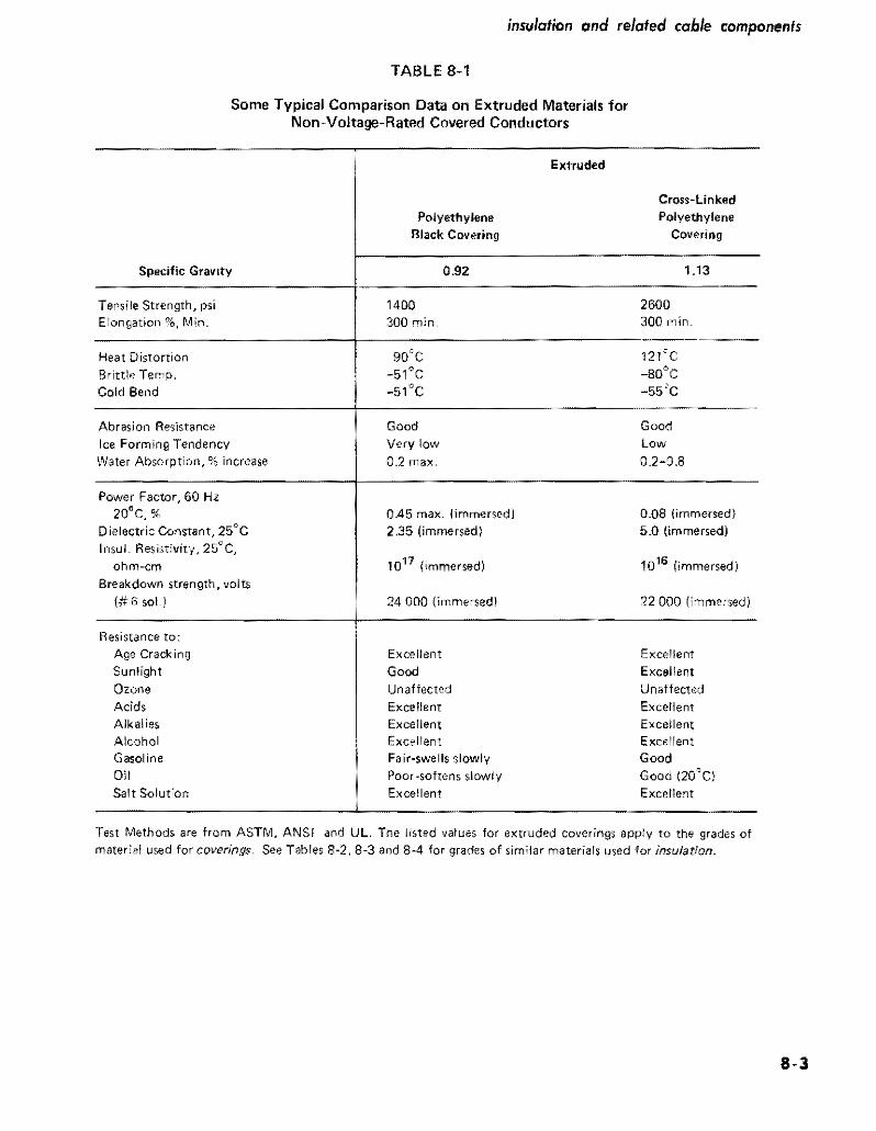
insulation and related cable components
TABLE 8-1
Some Typical Comparison Data on Extruded Materials for Non-Voltage-Rated Covered Conductors
Extruded
Specific Grav ity
Polyethylene Black Covering
Cross-Linked Polyethylene
Covering
092 113
Tense Strength psi Elongation Min
Heat Distortion Brittle Temp
Cold Bend
1400 300 min
2600 300 in
121C _80degC -55C
Abrasion Resistance Ice Forming Tendency Water Absorption increase
Good Very low
02 max
Good low 02-08
Power Factor 60 Hz 20degC
Dielectric Constant 25Q
C InsuL ResistIvity 25degC
ohm-em
Breakdown strength volts (6 soLI
045 max immersed 235 (immersed)
1017 (immersed)
24000 (immersedl
008 (immersed 50 (immersed)
1016 (immersed)
22000 (immersed)
Resistance to Age Crack ing Sunlight Ozone Acid Alkalies Alcohol Gasoline
Oil Salt Soluton
Excellent
Good Unaffected Excellent Excerlent Excellent Fair~swells slowly Poor-softens slowly Excellent
Excellent
Excellent Unaffected Excellent Excellent Excellent Good Good (20degC) Excellent
Test MethOds are from ASTM ANSI and UL The listed values for extruded coverings apply to the grades of mater used for coverings See Tables 8~2 8-3 and 8-4 for grades of similar materials used for insulation
8middot3
covered and insulated wire and cable
These materials are classified broadly as thermoplastic or thermosetting Thermoplastic compounds (polyvinyl chloride and polyethylenes - not cross-linked) soften upon exposure to heat Rubber compounds (natural and synthetic) are thermosetting that is upon exposure to heat under suitable conditions a chemical reaction occurs and ihe compound becomes vulcanized into a tough elastic condition Alihough polyethylene is classed as a thermoshyplastic it may be converted to a ihermosettng compound by bringing about a cross-linking of components after the material in its thermoplastic state has been extruded around the conductor Thus whereas polyethylene in its typical thermoplastic form has melted at approximately 105C in its cross-linked form it retains about 90 of its unaged property even at 121degC The other thermosetting rubber-like compounds if properly compounded also show high retention of initial hardness at high operating temshyperatures However comparisons of surface hardness at various temperatures may be misleading because the hardshyness usually can be controlled by additives and too hard a surface may be undesirable
The permissible temperature at which an insulated conshyductor can operate for the expected life of ihe cable withshyout impairment of insulation Quality determines the amshypacity (current-carrying capacity) of the conductor The higher the operating temperature the greater the ampacity High operating temperatures imply high losses in the cable and despite the ability of an insulation to withstand certain temperature levels without losing its insulating properties care must be exercised to determine economic conductor sizes to balance first cost and operating costs during the life of the installation
The performance of thermosetting and thermoplastic insulations for power cables has improved remarkably in recent years both as to permissible operating temperature and oiher electrical constants but also as to increase of useful life Early insulations were oxygen-sensitive that is ihey would age from exposure to oxygen in air In comshyparison modem insulations are compounded from mashyterials ihat essentially are insensitive to oxygen The early insulations for high-voltage cables also were required to pass an ozone test at 00100015 concentration for three hours Wiih the advent of modem insulations this concentration was doubled (0025-0030) Although ihe official test time still remains at ihree hours ihe test usually can be extended to 24 hours or even 48 hours without failure At this concentration the earlier materials would fail in minutes
The effect on the elongation of an insulation (or jacket) under stress is also an acceptable measure of heat resistshyance The air Oven test at 121degC provides a relatively quick method of grading insulation materials for use at high conductor temperatures or in hot-spot areas Alshythough the ICEA 121middotC air-oven test specifies that a minitnum of 75~ of the initial elongation must be retained after 7 days of exposure representative modem insulations for high voltage conductors actually show far better pershy
8middot4
formance typically as follows
Air-oven aging at 121 cc Percent of Initial Elongation at Rupture End of Period
7 Days 14 Days 21 Days 28 Days XLPE 98 95 91 84 EPM or EPDMu ~ ~ a Butyl 95 90 86 77
bull Cross-linked polyethylene EthyJene propylene rubber (EPR)
Further evidence of improvements in insulation perforshymance in these and other electrical and mechanical propershyties is evident from Tables 8-28-3 and 8-4 if the standards established for the earlier 60degC insulations are compared with those of later types for 75degC and up And from the above-mentioned values for air and oxygen aging and for retention of elongation it is evident that modem insula tions in some respects far exceed the requirements of established standards
The performance of a synthetic rubber or a sitnilar plastic insulation depends not only on ihe largest proportionate component of the compound (from which ihe insulation sometimes is named) but also on its formulation wiih modifying ingredients and on ihe meihod of manufacture The added ingredients are broadly grouped as vulcanizing agents or curatives accelerators that speed the reaction reinforcing agents ihat improve strength tear and abrasion resistance fillers such as carbon black clay or talc antioxidents that improve aging quality and plastishycizers ihat soften the compounds and provide control of flexibility
As ihe exact proportions of each of ihese ingredients and the conditions of preparation and mixing may differ among cable manufacturers insulations are not supplied to meet a component-and-process specification but in stead are supplied on a performance specification accord ing to standards and meihod of testing of American Soshyciety for Testing and Materials (ASTM) Underwriters Laboratories Inc (UL) and Insulated Cable Eugineers Assn (ICEA) The National Electrical Code (NEC) refers to various kinds of insulation as types and the sequence of letters of the NECType (such as RHW RHH THWN etc) provides an approximate description of insulation performance Page 8-12 explains the usual meaning 0 f these NEC Type letters
Thermosetting Insulating Materials
Styrene-Butadiene Synthetic Rubber (SBR)
This insulating compound was introduced after World War II it was originally called GRS (Government Rubshyber-Styrene) and was first made in government-owned plants New improvements in manufacturing have resulted in compounds that are even more desirable in many re
spects than natural-rubber base insulation References to synthetic rubber in Table 8-2 imply the use of SBR
The SBR compounds are suitable for many of the NEC Code rubber insulations of the RH RHH and RHW types and by change of modifying components they can be adapted to various conditions from 75degC wet or dry to low-temperature (_55degC) service where cold-bend brittleness and torsional stiffness requirements are severe Though normally used in the 0-600 volts range SBR can be compounded for high ozone resistance hence made suitable for cables to 15 kV It has limited resistance to oils and hydrocarbon fuels and has little resistance to flame propagation though this property can be improved by special compounding Hence a flame-retardant jacket must be used unless this special compounding is used Similarly an oil-resistant jacket can be applied if desired
SBR has good dielectric properties and relatively high dielectric strength As usually compounded it has excellent flexibility strength and resistance to tear and abrasion If desired for chemical environments the manufacturer should be consulted SBR also is much used in jacket comshypounds and particularly where a flexible jacket is required as on certain portable cables
Butyl Synthetic Rubber This compound is a copolymer of isoprene and isoshy
butylene and is inherently resistant to ozone hence it principally came into use for insulation at the higher voltshyages Butyl rubber has better electrical properties and greater heat and moisture resistance than either SBR or natural rubber Because of these properties it is possible to produce an ozone-resistant Insulation from butyl rubshyber of a given thickness that is superior to that of ozoneshyresistant SBR
The lCEA listing of ozone-resisting butyl rubber specifies 85C for 15 kV and 80degC for 28 kV (grounded neutral) Industry listS however place it in the 80degC class and as sultable for 15 kV (28 kV grounded neutral) with ungrounded neutral The air-aging and elongation tests (see page 8-4) show that this insulation liberally exceeds ICEA miulmum requirements
Cross-Linked Polyethylene Insulation (XLPE XHHW)
This insulation listed in NEC as Type XHHW and also suitable for underground gorvice entrance (USE) is classishyfied as thermosetting although its basic material is polyshyethylene which in usual form is thermoplastic The comshypound is obtained by introdUCing what is known as a crossshylinking agent to low-density thermoplastic polyethylene thereby converting it to a thermosetting compound The resulting compound still has the original excellent characteristics of polyethylene but in addition has high heat resistance it wiD no longer soften at 100C Because the cross-linking treatment is done at a higher temperature than that used for thermosetting most rubber compounds special equipment is required for the final processing of
insulation and related cable components
XLPE Its high qualiy is evidenced by ICEA listings per Table 8-4 for wet and dry locations at 90e C for normal operation The standard also lists it as suitable for l30C for emergency-overload conditions and 250degC for shortshycircuit conditions The usual availability of cables with this insulation is No2 AWG to 1000 kemil
Whne present lCEA standards only cover XLPE thru 35 kV AElC-5 recognizes higher voltages and considerable 46 kV cable is in service and smaller quantities of 69 and 115 kV cable have been furnished
Ethylene-Propylene Rubber (EPR) This ozone-resisting rubber insulation is recognized as
suitable for up to 35 kV at 90degC or 25 kV for ungrounded neutral (13370 insulation level) The insulation consists substantially of ethylene-propylene copolymer (EPM) or ethylene-propylene terpolymer (EPDM) The insulation is principally used for medium-voltage cables it has UL apshyproval and is recognized under the RHH -RHW type
Fluorinated Ethylene Propylene Rubber (FEP) Commercially this insulation is sometimes referred to
as Teflon It has excellent ozone-resistance and heat-aging within its 90degC dry and 75degC wet ratings It is much used for control wiring mostly in tbe smaller sizes up to No2 A WG for which it is UL approved NEe lists this insulashytion as suitable for Type RHW conductors
Neoprene Synthetic Rubber Neoprene is described as a Jackel (page 8-9) because its
relatively poor insulating quality limits its use as insulashytion However there are applications mostly for smallshysize conductors in which neoprene will be used as insulashytion because of its ability to withstand flame oil and abrashysion Sometimes it is better to use a thick coating of neoprene as an off$et to its poor insulating quality so as to obtain its other advantages without having to cover the conductor first with a high-quality insulation and follow it with a jacket of neoprene
Asbestos Insulations (SA A V A A VL) Aluminum conductor is hetter suited for high-temperashy
ture operation than most metals because its oxide coating does not become thicker as a result of repeated applications of heat The Type SA power cable is NEC listed to 2000 kcmil with an outer covering of asbestos or glass braid OVer silicone-rubber insulation The insulation is rCEA listed to 1000 kcmil for 125degC and is of ozone-resisting type The insulation compound is heatshycured fluorosilicon rubber a semi-organic polymer
Types AVA and A VL contaln no rubber The insulation is provided by a layer of varnished cloth between inner and outer walls of felted asbestos impregnated with a satushyrant Type AVA has an asbestos-braid outer covering Type A VL has a lead sheath Type AVA is used in dry locations and A VL where the cable may be submerged or subjected to excessive condenSltion
8-5
TABLE 8-2 n00bull o 0shy
Specifications tor Natural- and Synthetic-Rubber Insulations ~ ~ Abstract from ICEA-NEMA Publication 8-19middot81 Q
LICEA $middot19-81 Paragfllph No 2 R~nlbjes Ul NEC 3 Description
4 Temp dry nN ej(cm~ding c 5 Temp wet not excooding 0 C
Max kV phltl~emiddotW1Jh~w
6 with grOlJl1ded I1Nltrnl 7 with url~rounded neutral
8 Ten~ile strength psi min 9 ElongatiOIl ~t fUl)tUW min
Aging requirements (air fln1ssure) 10 Tast at~OC for_hrs
Vflues as unflged value 11 Tensile slrenjJlh IIlin 12 Elongation min
Aging requirements (oxY(lenJ 13 Test at ~oC for _hrs
Valuas as unaged valun Tensile S-etlglh min
15 ElongatiOn min
Insulation resi~lance shy16 Parameter K
Accelerated water absorption EM60 Increase in capadyoce max
17 1 to 14 days
8 710 14 days 19 St~bility factor after 14 days
Gravimelric method m~x aborpshy20 don milgramssq in
21 Oielectric constant at foom lemper31un 21 Power factor __1tHII_kV
Ozone resistance No cracks after 3 hrs exposure 10 cocttnra~
Han of not less than ~ nor more than_ by volume
-
Min Corona level wilh 24 grounded neutral t 5 kV 25 $ilme a115 kV
S3Jl RW
Syntheti( Rubber
60 60
2 700 300
70-9S
75 65
2000
100 30 10
200
suo Ali
Synthehr Rubber
75
2
700 300
127middot20
50 50
aO w 168
W 50
2000
$311 RU-RW
SynhEttle Ruhhnr
60 2
700 300
127-20
50 0
80-168
50 50
2000
100 30 bull 0
200
5312 RH
Natural Rubber
75
2 2
1500 400
117-20
50 00
aO-168
75 76
1Ob60
5313 RHW
Synthelic Rubber
75 75
2 2
700 300
127-20
50 50
aO-168
50 50
4000
100 40 10
200
5314
Ol()ne-Re~isting
Natural or Syntflltic Ruhbnr
75 70 75 70
8kV2BkV 8kV15kV
450 250
70_1S8 4
400 200~
70-48
400~
200
2000
100 30 10
50 50 abffile
5kV
0010(1015
40 110
S)15
Olone-Resisting Butyl Rubber
0 80 85 80
15kV2BkV 15kV15kV
600 3)0
100middot1Sfl
GO 60
air pressure 12-40
50 50
2OPOO
50 30 10
150
45 35 ijbove
bkV
0025-0030
40 110
S316 RHH
Sy1the~ic
Rubber
90
2 2
700 300
1gt1middot168
60 60
air pressu9 121-42
50 50
4000
5311 SA
OzonB Rllsistl1)9 Silicone Rubhor (0 1000 Reml
125 125
5 5
800 250
200middot16B
500 H
125 B
4000
10 a3raquo
150
O025middotLOJO
40
g Q
S ~ it Q
~ ~
Q Q
8 0shym
26 at rIlax_kV_kV BkV 210 28 kV 210
Aif-Oven rest Oiscrete minimum IiClues for tenSilf) slrength psi) and f~longatjon (pereend rather thall pampfCerlt of unllle value
NOTE The publications from which this lable is an ab-s(tIra cOlltaill el(Ceptioll$ ~riiilliot$ of certain of Ihe values that aflply under speci~1 conditionlt hence this tble should bamp med only for jeneral reference Actual df$ign requinK U5e of the complete speci[Ciiltions Consult sp~~cificlltion5 illso for explar1atior1 of the villiou items
1tems ) and 7 fnsutiJtion~ specified for 15 kV Me in extensivtl comrfl6rrilt uw al t(ltI~t to35 kV
Item 13 nsulalion~ 5315 lnd 5316 are ~ubjecte-d 10 ~rl air-prenure te~1 ill~tcad (rar-Ql(ygEnprt~sure teU The XLPE anO XLHHW in~ulatlons under90 B healshylistOftOfl test
ThrlisleJ 1lt IS used in the rollowing lorrnutiJ tor irHulntion fesistnnce 1(l910 (Did) wherr R ~ resisti30ce in meJohm~
for 1000 ft D dlamrler over the insulation and (I = diamrler under thE inulrtiol1
insulation cnd related cable components
TABLE 8-3
Specifications for Thermoplastic Insulations Abstract from ICEA-NEMA Standards 5-61-402 WC-5
S39 Low Density
1 ICEA S-61-402 Paragraph No S37 S38
Polyethylene
Chloride 60C Chloride 75C Polyvinyl Polyvinyl2 Description
HMWType I Classes A Bor C
7560 753 Temp dry not exceeding degc 75
Max kV phase-to-phase 4 Temp wet not exceeding degc 60 75
06 06 3505 with grounded neutral 2506 with ungrounded neutral 06 06
14001500 20007 Tensile strength pSI min 3508 Elongation at rupture min 100 150
Aging requirements (air-oven) 100-48
Values as 0 unaged value 9 Test at_OC for_hrs 100-168 121-168
7510 Tensile strength min 65 80 75
Aging requirements (oil immersion) 45 5011 Elongation min
12 Test at degc for_hrs 70-4 70-4 Values as unaged value
13 Tensile strength min 80 80 14 Elongation min 60 60
15 Insulation resistance - Parameter K 500 2000 50000
Accelerated water absorption EM60 Increase in capacitance max
100 4016 1 to 14 days 17 7 to 14 days 50 20
Gravimetric method max absorption
lB milligramssq in 100200
Min Corona level with 419 grounded neutral at 5 kV
1120 same at 15 kV 35 kV-2621 same_Max kV_kV
Note For information regarding jackelJ of these materials see Table 8-5 See also Note on Table 8-2 (1 The kV ratings for polyvinyl chloride insulation are increased to 1 kV for control circuits and to 5 kV for series lighting circuits Carbon-black pigmented polyethylene is not to be used On power cable rated over 5 kV Strength and elongation aging values apply to AWG sizes No6 and larger See also AEIC-5 for thermoplastic primary cables
8middot7
covered and insulated wire and cable
TABLE 8-4
Specifications for Cross-Linked Thermosetting Polyethylene and Ethylene-Propylene Rubber Insulations
Abstract from ICEA-NEMA Standards Publications S-66-524 and S-68-516
1 ICEA S-66-524 Paragraph No
2 ICEA S-68-516 Paragraph No
3 Resembles UL NEC
4 Description
5 Temp dry not exceeding degc 6 Temp wet not exceeding degc
Max kV phase-to-phase 7 8
with grounded neutral
with ungrounded neutral
9 Tensile strength psi min 10 Elongation at rupture min
Aging requirements (air-oven) 11 Test at_DC for_hrs
12 13
Values as unaged value
Tensile strength min Elongation min
14 Insulation resistance - Parameter K
Accelerated water absorption EM60 increase in capacitance max
15 1 to 14 days 16 7 to 14 days 17 Stability factor after 14 days
Gravimetric method max absorption 18 milligramssq in
19 Dielectric constant at room temp 20 Power factor_ at_kV
Min Corona Level with
21 grounded neutral at 5 kV 22 same at 15 kV 23 _same_max kV_kV
36
XLPE
Cross-Linked Thermosetting Polyethylene
90 90
35 25
800 250
121-168
75 75
10000
30 15 10
35 20
37
XHHWamp USE
Cross-Linked Thermosetting Polyethylene
90 90
2 2
1800 250
121-168
75 75
20000
30 15 10
60 20 above
5kV
40 110
35 kV-260
36
EPR
Ozone Resisting Ethylene
Propylene Rubber
90 90
35 25
700 250
121-168
75 75
20000
30 15 10
100
40 above 5kV
40 110
35 kV-260
See also AEIC-5 for XLPE primary cables and AEIC-6 for EPR primary cables
8-8
Thermoplastic Insulating Materials Unlike thermosetting compounds thermoplastic insulashy
tions remain plastic regardless of temperature and conseshyquently will soften or melt at temperatures that would not significantly affect thermosetting insulations The principal thermoplastic materials used for insulations have a resishynous base classified as polyvinyl chlorides and polyshyethylenes (not cross-linked) No vulcanization is required although ingredients are added to the mixture for quality control and to facilitate extrusion on the conductor
Thermoplastic Polyvinyl Chloride (PVC) This compound is not a synthetic rubber Basically it is a
resin of high molecular weight polyvinyl chloride or the copolymer of vinyl chloride and vinyl acetate Plasticizers stabilizers fillers and lubricants are added to meet apshyplication conditions PVC is often used for insulation and jackets particularly in oil or petroleum environments PVC loses from a third tgt half its hardness at 100degC and melts at about 140degC For some of its other physical and its electrical properties see Table 8-3
PVC insulating compounds are available for Type TW (NEC) insulation rated 60degC wet and dry fOr Type THW rated 75degC wet and dry for THHN rated 90degC dry and for higher temperatures as appliance wire consideration of which is beyond the scope of this book
Thermoplastic Polyethylene (PE) This material in its low density high-molecular weight
grade is used as the base from which thermosetting crossshylinked polyethylene is made as previously described Polyshyethylene of the same grade without cross-linking is specishyfied by ICEA as suitable for insulation of conductors for rated voltages to 35 kV for up to 75degC in dry Or wet locashytions This PE grade is subject to the ill-effects of ultrashyviolet lijiht (sunshine exposure) which can be corrected by jacketing with a similar material containing not less than 2 carbon black (PE-Black) or if not over 5 kV the pigment may be incorporated in the insulation
Polyethylene can be treated with chloro-sulphonic acid reSUlting in Hypawn which can be compounded in a manshyner similar to rubber Its electrical and moisture-resisting properties do not equal those of untreated PE but the aging characteristics are excellent
There are numerous grades and classifications of polyshyethylenes only a few of which are suitable for insuiations Table 8-3 lists the properties obtainable from Type I high molecular weight low-density polyethylene
The high-density low-molecular-weight polyethylene (black) is a compound used for insulation and covshyering on secondary line wire and service drops because of its exceilent resistance to abrasion The effect of reshypeated rubbing of tree branches and leaves that often surshyround such conductors is greatly reduced as is the cost of tree trimming
insulation and related cable components
Jacket Materials As has been stated often the most suitable insulation
for resisting dielectric stress may not have an outer surface that is suitable for the conditions which the cable must meet in service Thus for improvement in resistance to flame oil abrasion and chemical environment a suitable jacket is extruded around the insulated conductor Though the jacket may have moderate insulating quality its princishypal function is to protect the underlying cable components
Because one side of the jacket is at ambient temperature and the other is one the outside of the insulation the rated temperature for the jacket materials can be somewhat less than that of the insulation For this reason jackets may be of thermoplastic material Table 8-5 lists jacket properties according to ICEA
Polyvinyl Chloride lackels
The compound for polyvinyl chloride jackets closely reshysembles that used for PVC-60 insulation (S37 of Table 8-3) It is used for jacketing single- and muiti-conductor cables particularly when shielded These jackets provide toughness resistance to moisture and oil and have good low-temperature properties As regularly supplied they withstand reel bending at installation temperatures of -lOoC and if specially compounded as for mine cable are suitable under oil conditions in the range -10degC to 90degC Cables with PVC jackets are suitable for installation in conduit trough or tray underground ducts direct-earth burial and overhead on messengers
Polyethylene lackets
Black low-molecular weight (high-density) and highshymolecular weight (low-density) polyethylenes are frequentshyly used as jacketing material The 2 percent black pigment prevents deterioration from ultra-violet rays of sunlight PE jackets have specific application where extreme resistance to moisture and abrasion is required
Neoprene lackets Neoprene is a polymer of chloroprene containing about
38 of chlorine which accounts for its excellent flame and oil resistance It has comparatively high moisture abshysorption which with only moderate dielectric properties limits its use mostly for jackets Though oil resistant oil will pass through the material hence cable components under a neoprene jacket also must be oil resistant if that quality is required The properties of general-purpose neoprene and typical heavy-duty neoprene are listed in Table 8-5 General-purpose neoprene jackets are suitable for use On low-voltage cable or on high-voltage shielded cable when Ozone resistance is not required It is generaUy resistant to mechanical abuse Qils water chemicals and flame The heavy-duty neoprene jackets may be forshymulated to meet several conditions either singly or in comshybination thus extra protection against mechanical
8-9
covered and insulated wire and cable
damage water chemicals or flame extra-heavy duty for portable cables arctic type for extremely low temperatures and heat-resistant type for high temperatures
Nylon Jackets Nylon is a generic term for polyamide polymers This
material is a tough abrasion-resistant thermoplastic which can be extruded as a thin protective covering over PVC or PE insulation thereby improving its ability to withshystand damage to insulation from mechanical abrasion and cold flow Because of its poor electrical properties nylon is not used by itself as insulation
Nylon jackets are specified for several of the thermoshyplastic insulations listed in NEC thereby enabling thinner insulation to be used with resulting reduction of size of conduit and it is also used on control wire and similar constructions
Nitrile-ButadienePolyvinyl-Chloride Jackets This jacket consists of a vulcanized acrylonitrile-butashy
dienepolyvinyl-chloride compound based on a fluxed blend of acrylonitrile-butadiene synthetic rubber and polyshyvinyl-chloride resin It is made in two forms general-purshypose and heavy duty the latter having higher tensile strength and greater elongation at rupture (its tensile strength at 200 percent elongation is 500 psi) hence well suited where bending is a requirement as in portable cables
uUnipass Jackets
This construction is obtained merely by increasing the thickness of the insulation which is extruded by a single pass By virtue of the inherent toughness of the insulation surface a nominal increase of the insulation thickness over what is required for the voltage rating is regarded as the equivalent of a separate jacket This process is only suitshyable if the insulation surface is satisfactory to meet inshystallation conditions
No Jacket Requirements In this category are the single-conductor NEC Types TW
and THW and the RHW-RHH and XHHW cross-linked polyethylene insulated cables These cables have no jacket over the insulation and the insulation is not increased in thickness because of lack of jacket The normal insulation surface is considered sufficiently tough to resist normal conditions Some of these conductors however require inshystallation in conduit duct or on rigid supports to meet NEC requirements
Tapes and Shielding Materials
As outlined on page 8-1 the materials required to comshyplete a cable other than conductor inSUlation and jacket depend on kV rating and whether or not the cable is to have conductor shielding and insulation shielding
Insulating Tapes Insulating tapes of various kinds are sometimes used in
the assembly of single- or multi-conductor cables and they also are used for insulation at spikes and terminals The desired requirements for a tape suitable for the insulashytion body of a splice or terminal are as follows (I) dielecshytric constant not over 32 (2) can be stretched to just short of its breaking point during application and (3) bas a shelf life before use of at least 5 years without loss of quality Polyvinyl chloride tape of lesser insulation quality (dielecshytric constant up to 100) but well suited for exterior use is also used as a covering over the main insulation body of splices and terminals Semi-conducting and metallic tapes also are used for shielding and for splicing the shielding Care must be taken to ensure that the tape is compatible with the components on which it is placed
Shielding Materials and Shielding Methods
Insulation shields consist of metallic non-magnetic tape braid wires or sheaths A fibrous or other nonmetallic covering either conducting or non-conducting is applied over the insulation An additional covering may be applied over the first one if the finlt is conducting the outer one also must be conducting Metal-tape shields must be elecshytrically continuous Similar insulation shielding may be of metal braid Or of concentric round wires
Shielding of multiple-conductor cables is applied over the insulation of the individual conductors except that if the shielding is only for the purpose of reducing shock it may be applied over the whole conductor assembly For singie-conductor cable the shielding effect of tubular corshyrugated or interlocked armor is supplemented by auxiiiary nonmetallic shielding in intimate contact with the insulashytion and the metallic outer covering or sheath A separate metallic shield is not required However when an insushylating tape is bonded to the insulation the tape is conshysidered to be a part of the insulation and the auxiliary nonmetallic shield should be applied directly over the inshysulating tape
Insulation shielding is sometimes used as part of a cirshycuit for relaying or for locating fault position Considerashytion of such uses are beyond the scope of this book as is description of the conditions under which the shield is open-circuited short-circuited and grounded
Conductor shieldS consist of conducting nonmetallic tape extruded compound or cement They are applied over the surface of the conductor
The various thicknesses of both insulation and conducshytor shields are specified by ICBA for the various types of cables and applications
The Effect of Corona on Insulation and Shielding
As described in Chapter 3 whenever air is stressed electrically beyond its breakdown point the air will ionize
8-10
insulation and relaled cable components
TABLE 8-5
Specifications for Rubber Or Thermoplastic Jackets for Insulated Conductors and Cables Abstract from ICEA-NEMA Publication S-19-81-WC-3
i leEA S-19-81 Paragfaph No
2 Description
3 Minimum temperampure for cold weather appiea tions
4 Tensile strength psi min 5 Elongation at rupture min
Aging requirements ( air~oven)
6 Test at c for hr
Values as Unltliged v alue 7 Tensile strength min B Elongation min
Aging requirements ( oxygen pressure) 9 Test at QC fOT hIs
Values as unaged value 10 Tensile strength min 11 Elongationmin
12 Oil immersion at degc for hr
Values as unaged v alue
5413554132 I 84123 I S4134 1
I
I 13 Tensile strength min 60I 14 Elongation min 60
Neoprene
General
Purpose
Black amp Polyvinyl
Colors Chloride
-10C
1500 1500 250 100
100-lt8 100-5 days
85 50 50
60
54136
POlyshy
ethylene Black
-40C
1400 350
100-48
75 75
5413854137
Nitrile Nitrile
Butadiene Butadiene
PVC- PVC-
Brack amp Blackamp
Colors ColorsI Heavy General
PlIrposeOlltY
-2Sgte-25e
1800 1500 500 250
100-68 100-pound8
50 50 50 50
I 121-18 70-4 121-18 121-18
60 80 I I
60 60
60 60 60 60
54139
Chloro-
Sulph~
onate Poly-
Ethylene
Heavy
Dutyi
Synthetic
Rubber
5BR
1800 300
70-168
1600
Neoprene
Heavy
Duty Black
1800 300
100-lt8
50
I 60
1
Because the temperature gradientthrough insulation and jacket during operation assures a comparatively coo jacket the minimum air temperature at which jacket cracking will not oltcur is listed
Dlscrete minimum values for tensile strength psi) and elongation (percent) rather than percent of unaged value
Appficable to materials having a nominal thickness of 0030 in and up See also NOTE on Table 8~2
NOTE The airN 3ging tests for neoprene ~ackets for portable cables are based on 70e for 168 hrs instead of 127C for 20 hrs The oxygen test fOr 54135 is omitted but an oil-immersion test is made
NOTE Some of these jacket materials also are used as weatherproof semi~insulation coverings where conductor rating does not exceed 600 volts phases-to-Phase
1800 300
100-68
85
65
121-18
60
250 50i
70-96
1600 250
121-18 I
8-11
covered and insulated wire and cable
with the emission of ozone The visible manifestation of this ionization is corona the characteristic bluish glow that sometimes can be seen at night along bare overhead highvoJtage transmission lines It is not only necessary that the insulation have suitable resistance to the chemical action of ozone but it also must withstand the tendency for burning that may occur as a result of corona~discharge current
Coronadischarge eflects are greatest in voids in the inshysulation or between conductor and insulation Or shielding A corona-level test determines the absence of such voids that can cause local deterioration of the insulation proshyvided the actual operating voltage is less than the rated corona-level voltage
The coronalevel values listed in Tables 8-2 8-3 and 8-4 are to be considered in relation to phasetoground voltage Thus for insulation described in Col S3IS of Table 8-2 a cable used in a threephase 15 kV circuit has line-toshyneutral voltage of 150173 = 87 kV The corona-level requirement is listed as IIOkVhenceinsulation thickness that meets this requirement is suitable provided it is satisfactory otherwise
The strand and insulation shields are so designed as to prevent ionization between the inner surface of the insulashytion and the conductor and its outer surface and the metallic insulation shield A simpler form of insulation shielding is provided by the use of concentrically applied wires for potential-gradient control
Sheaths Fillers and Binders The various kinds of metal-clad armored or sheathshy
enclosed cables are described in other chapters Additional details as to the sheath materials as well as fillers and binders overall jacketing etc are in ICEA and NEC publications
ICEA Performance Specifications As previously mentioned insulation and related mashy
terials for cables are specified according to performance inshystead of by composition and processing An abstract of the principal performance values applying to commercial insulations is in Tables 8-2 8-3 and 8-4 which with the explanatory footnotes provide data as a guide to insulation selection Similar information applying to jacket materials is in Table 8-5 Several early-type insulations stiD are listed in the ICEA publication from whlch Table 82 was compilshyed but they are purposely omitted from Table 8-2 because they are obsolete
The following explanation of some of the terms used in the tables may aid their use Further details are in the referenced ICEA publications
Insulation Resistance (K (item 6) and formula in note to Table 82)
The insulation resistance is obtained in megohms for a cable 1000 it long measured after one-minutes applicashy
8middot12
tion of constant dc potential As the resistance is meashysured through the insulation to the outer surface the elements of current are in parallel hence the insulation resistance will be one-half as much for a cable length of 2000 ft Or ten times as much for a cable 100 ft long The test to determine one-minute dc insulation resistance by use of an immersed cable is at 156degC and made after a constant dc potential has been applied for one minute The ICEA standards contain adjustment factors for other temperatures This one-minute de value of insulation resistance principally is used for rough comparison of insulation quality and it is far from accurate because tests at other times than one minute may show wide differences and under ac conditions a different value is obtained See Appendix 8A for further discussion of insulation resistance R lac) under aC conditions
Waler Absorption By use of the electric method the increase in capacishy
tance ahove tbat of a dried block of insulating material when it is immersed and subjected to 60 Hz (EM 60 test) is an indication of the water absorption as compared with results of similar tests on other insulations By use of the gravimetric method the actual increase in weight of the dried specimen of standard size after immersion for a specified time is divided by the total surface area of the specimen
Temperature Tables 8-2 8-3 and 8-4 list only tbe maximum
temperature for normal operation Because of occasional operation at a higher temperature (emergency-overload conditions) or for an extremely short time (short-ltircuit conditions) additional data from the ICEA standards is supplied for some of the insulations in Table 9-7
NEC Designations The following summary of the most commonly used
NEC letter-designations used for describing insulations and cable constructions may be helpful for understanding specifications that include NEC abbreviations This sumshymary relates only to power cables of the usual kinds There are limitations and exceptions so the abbreviations must be used with caution Refer to NEC for full information
Insulation Materials
R = Rubber (natural or synthetic) T = Thermoplastic usually flame-retardant polyvinyl
chloride or polyethylene However TA and TBS are not flame retardant though can be made so by suitable outer covering
X = Cross-linked thermosetting polyethylene as used XHHW
FEP =Fluorinated ethylene propylene
insulation and related cable components
Heat-Resistant Quality
Without H = Usually suitable for 60C H = Usually suitable for 75C HH Usually suitable for 90C (except XHHW only
when dry)
Moisture and Oil-Resistant Quality
Without W = Usually suitable for dry locations W = Usually suitable for wet and dry locations M = Usually suitable for oily conditions (machine-tool
circuits) Do not confuse with M for metal as part of MC (metal-dad) for instance
Jackets and Sheaths (as part of a single conductor)
Note NEC does not use abbreviations for several jacketing materials (see Table 8-5)
]I Nylon
BS Fibrous braid
B = Glass mica or asbestos braid
L = Lead sheath
NEC Cable Constructions
MC Metal-clad with interlocking armor or close-fitshyting corrugated tube
AC Armor-clad with flexible metal tape
ACL Same as AC but with lead sheath
ACT Same as AC but the moisture-resistant fibrous covering need only be on the idividual conductors
NM Nonmetallic sheathed cable
NMC Same as NM but must be fungus and corrosion resistant
SE Service-entrance cable (also suitable for interior wiring under certain conditions) Not suitable for direct burial
USE Underground service entrance cable also suitshyable for direct burial
UF Underground feeder cable also suitable for direct burial under certain conditions
Insulating Compounds designated by NEC symbols
If the symbol contains R the compound is principally synthetic or natural rubber if it contains T it is a thermoplastic material if it contains X it is a crossshylinked thermosetting material Other letters are as previously indicated eg N indicates nylon jacketing
RW or TW for dry or wet locations at 60degC RH for dry locations at 75C RHH Or THHN for dry locations at 90C RHW THW or THWN for dry or wet locations at 75C XHHW for dry locations at 90degC and wet at 75C
APPENDIX 8A
Elements of Dielectric Theory
This appendix contains information that is generally understood by electrical engineers but it may be helpful as a reference to some of the terms used in the tables and as the basis for calculation of charging current
Dielectric Constant () Also designated specific inductive capacity (k) relative permittivity and similar terms
For a vacuum = I and for air it is 10006 hence for engineering calculations the difference is neglected The dielectric constant laquo) of a substance is the ratio of the capacitance of a condenser with the substance as the dielecshytric to the capacitance of the condenser with air as the dielectric
Thus an insulator with a large lt acquires a greater charge of electricity in coulombs Q for a given potential difference between its faces than will an insulator with a small The capacitance C of an insulator usually measshyured in microfarads is thus proportional to lt provided
conditions of temperature time dryness and applied voltshyage are the same A low lt is an apparent indication of superior insulation qUality However a low lt when dry may be much increased because of water absorption or other factors and such variations are different in various materials
Charging Current and Leakage-Conduclion Current It is convenient to consider the current input into an
insulator after voltage is applied as being in two parts (I) a charging (or displacement) current Ic that serves to inshycrease the potential of the insulator by accumulating a quantity of electricity (coulombs Q) in the body of the insulator and (2) a leakage-conduction current ie in phase with the applied voltage that supplies energy to heat the insulator (hecause of it internal dielectric stresses) and to supply the energy losses associated with the current that passes through the insulator or across its sudace
8-13
covered and insvlated wire and cable
The charging current Ic does not represent energy loss because after withdrawal of the voltage an equal current is discharged from the dielectric The leakage-conduction current Ie represents energy loss Ele or as indicated by the relationship R = Ell in which R is the insulation resistance as usually measured according to lCEA stanshydard assuming standard conditions (see page 8-12) of Chapter 8 and Tables 8-2 through 8-5) The insulation resistance varies through a wide range depending on the dielectric and temperature as shown by Table 8A-I which is an abstract of Table 6-21 of lCEA Standard S-19-81
Charging and Leakage-Conduction CurrentS Under Direct and A temating Potential
Because insulation resistance is found by test under continuous application of potential (for one minute acshycording to ICEA standard) the rate of increase of charge Q within the insulator and the consequent rate of reduction of input current Ic will differ from what occurs when the emf is alternating as is the usual condition When a constant dc emf is applied an appreciable time is required for the insulation to acquire its full charge if its lt is greater than I For some insulations it may take a half hour or more for equilibrium to be achieved so no further charging current flows
When subjected to alternating potential however the insulator (dielectric) is being charged and discharged at short intervals (l I 120 sec at 60 Hz) Less than a full charge is acquired by the insulator at each voltage peak because the time is so short This effect under alternating potential is taken into account by the concept of Capacishytive Reactance X in ohms as follows
Xc = I I (2 f C) (Eq SA-l)
where f = frequency Hz C == capacitance in farads for the stated frequency
Many tables only show Xc The corresponding value of C is readily determined by inverting the above equation to C= 1 (2fXc)
The charging current Ic in amperes is as follows
E (to neUIngt)I = 2f C (Eq 8A-2)
Xc
where E = volts to neutral and the other terms are as previously defined In practice Jc is obtained from tables nomogram or formula in a similar manner as described in Chapter 3 for bare conductors
middotIt is important to distinguish between the insulation resistakce R measured at one minute after applying de potential according to the leBA test method and R(ocJ that reflects the reduced capacitance under ac conditions The latter value is a function of charging curtent Ie at the given frequency and insu~ation power f~ that is R(fIC= E1c x pf in wftich E is volts to neutral (see the next section and example at end of this Appendix)
The leakage-conduction current Ie may be calculated from data as to insulation resistance after correction for temperature or by multiplying the charging current by the power factor that often is listed as a property of the insulation
Total Dielectric Current and Power Factor Under aC Conditions
The charging current Ic depends on rate of change of applied voltage hence its peak occurs when the voltage is changing at its most rapid rate ie when the voltage is at zero point of its wave The leakage-conduction current leis in phase with voltage The two currents and voltage are shown vcctorially in Fig 8A-1 The resultant of Ic and Ie shown as I is slightly out of phase with Ic by angle 8 The power factor of the insulation is the ratio of Ie to Ie closely equal to tan Ii and it is usually expressed as a percent that is if Iellc is 0005 the power factor is usually designated as 05
- 2 bullThe total dielectric currentIl= (Ie + Iegt Usually Ie
is so small with reference to Ic that it is neglected and the charging current Ic is considered to be the total dielectric Current 1
Dielectric Constant () Under ac Conditions The calculation of dielectric constant hy measuring
capacitance under conditions of steadily applied constant potential is not practicable for insulated-conductor studies Instead the usual practice is to find the capacitance of a cable of specified size and length under ac potential of specified frequency and to compute the dielectric constant from the known relation that the capacitance of the air space occupied by the volume of insulation is 10 Then by geometry and suitable conversion of terms
Dielectric Constant () = 13 600 C 10g10 (Did)
where (Eq 8A-3) C = Capacity in microfarads of a 10-ft section of
cable at 60 Hz D = Diameter over the insulation in any units d = Diameter under the insulation in the same units
Capacitance of the cable also may be determined when frequency is 1000 Hz but it should be so stated
Capacitance of Insulated Aerial Cables The capacitance of an insulated Cable with ungrounded
sheath suspended in an overhead distribution line and well separated from the return conductor is practically the same as that of a bare conductor under the same conshyditions The slight increase in capacity of the insulation caused hy an lt greater than 10 extends through such a small distance (the thickness of the insulation) that it does not significantly affect the capacity (or the capacitive reactance Xc) between the condlltctors Hence the tables in Chapter 4 for shunt capacitive reactance may be used for both bare and insulated conductors suspended comshyparatively far apart
8-14
insulaion and related cable components
-Fig 8-AI Vectorial Relationship of Charging Current Ie Leakage-Conduction Current Ie and Total Dielectric Current I in an insulator in time-relationship with EMF vector E IeIe == tan ~ Power Factor
TABLE 8A-1
Typical Temperature Corrections for Insulation Resistance at 156degC (60Q F) for Otller Temperatures An Abstract of Table 6-21 of ICEA 8-19-81 (1980)
NOTE From insulation test report the ratio of insulation resistance at 61degF to its value at 60degF is noted thereby obtaining Coefficient for oF which is used to select which vertical column is used Thus assuming the Coefficient is 106 and insulation resistance at 15SoC is 133 X 1013 ohms for 1000 ft the resistance at 239
QC (75F) is 240 X 133 X 1013 =
319 X 1013 ohms for 1000 ft As the resistances for adjacent lengths are in parallel the resistance of a 2000 it length is one-half of that of 1000 ft and for 100ft is ten times as much
Temperatur Coefficient for 10
F
Fe CO 103 104 105 106 107 108 109 110 111 112
50 100 074 068 061 056 051 OA6 042 039 035 032
55 128 086 082 078 075 071 068 065 062 059 057
60 156 100 100 100 100 100 100 100 100 100 100
65 183 116 122 128 134 lAO 147 154 161 1S9 176
70 211 134 148 163 179 197 216 237 259 284 311
75 239 156 180 208 240 276 317 364 418 478 547
80 267 181 219 265 321 387 466 560 673 806 965 85 294 209 267 339 429 543 685 862 108 136 170
NOTE Linear interpolation in the vertical columns is satisfactory or a curve may be draw
8middot15
covered and insulated wire and cable
Capacitance of Insulated Conductors With Grounded Sheath or Directly Buried
Where the insulated conductor has a grounded sheath its capacitance is a function of diameter insulation thickshyness and dielectric constant of the insulating material n as follows
C = (000736 X lt)logbull (Did)
where (Eq8A-4)
C = Capacitance in ffarad per 1000 ft euror = Dielectric constant D = Outside diameter of insulated conductor d = Diameter of metallic conductor
An approximation of C for an insulated conductor withshyout metallic grounded sheath but contained within a grounded metallic duct may be obtained from the above equation if an average D is estimated and is reduced to take into account that of air is 10 applying to the space between the exterior of the conductor insulation and the metal duct
Example of Dielectric Computation
The previously stated principles are the basis of the folshylowing computation Given
A 40 AWG aluminum single conductor 19 strands 0528 diameter a semi-conducting tape strand shield and 0110 wall of cross-linked polyethylene insulation in meshytallic sheath in 3-phase circuit at 24 kV with grounded neutral 60 Hz For this cable the dielectric constant is 27 and power factor tan 8 is 01 or 10
Find
Capacitance microfarads per 1000 ft designated as C ac Resistance megohms for 1000 ft designated as R(ac) Charging current amperes per loooft designated as Ie Dielectric loss watts per 1000 ft
From Eq 8A-4
D = 0528 + 2 (0110) = 0748 in d = 0528 in Did = 1417 log 1417 = 01513 and substituting in Eq8A-4 C = (000736 X 27)01513 = 01313 farads per 1000 ft
The following relationship is also known Ian 8 = 001 = IPe = (E1Rae) I (2lT fC) = III (2 IT fC Rae) in which C is in farads
Substitutirg transposing and expressing 01313 pfarad as farads
R - I ac - 2lT X 60 x 01313 X 10-6 x 001
2 020000 ohms for 1000 ft (202 megohms)
E to neutral (volts) Charging current Ie = -------shy
11 (2f C (farads)
24_00---X2_-X--60_X--0_1_3_13_ = 00686 amp per 1000 it
3 X 1 000000
Watts loss 00686 X 2400 X OoI 0951
per conductor IE= _ --- shywatts3 per
1000 ft
8middot16
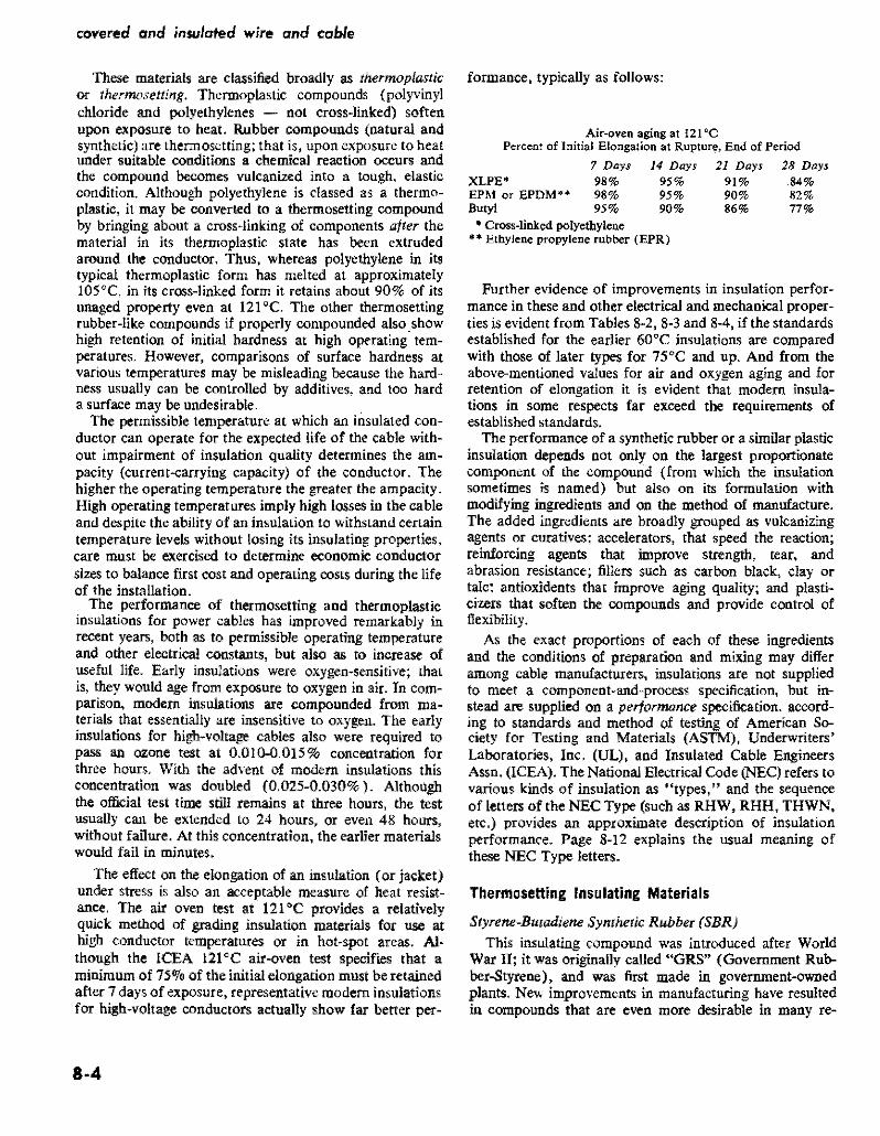
covered and insulated wire and cable
These materials are classified broadly as thermoplastic or thermosetting Thermoplastic compounds (polyvinyl chloride and polyethylenes - not cross-linked) soften upon exposure to heat Rubber compounds (natural and synthetic) are thermosetting that is upon exposure to heat under suitable conditions a chemical reaction occurs and ihe compound becomes vulcanized into a tough elastic condition Alihough polyethylene is classed as a thermoshyplastic it may be converted to a ihermosettng compound by bringing about a cross-linking of components after the material in its thermoplastic state has been extruded around the conductor Thus whereas polyethylene in its typical thermoplastic form has melted at approximately 105C in its cross-linked form it retains about 90 of its unaged property even at 121degC The other thermosetting rubber-like compounds if properly compounded also show high retention of initial hardness at high operating temshyperatures However comparisons of surface hardness at various temperatures may be misleading because the hardshyness usually can be controlled by additives and too hard a surface may be undesirable
The permissible temperature at which an insulated conshyductor can operate for the expected life of ihe cable withshyout impairment of insulation Quality determines the amshypacity (current-carrying capacity) of the conductor The higher the operating temperature the greater the ampacity High operating temperatures imply high losses in the cable and despite the ability of an insulation to withstand certain temperature levels without losing its insulating properties care must be exercised to determine economic conductor sizes to balance first cost and operating costs during the life of the installation
The performance of thermosetting and thermoplastic insulations for power cables has improved remarkably in recent years both as to permissible operating temperature and oiher electrical constants but also as to increase of useful life Early insulations were oxygen-sensitive that is ihey would age from exposure to oxygen in air In comshyparison modem insulations are compounded from mashyterials ihat essentially are insensitive to oxygen The early insulations for high-voltage cables also were required to pass an ozone test at 00100015 concentration for three hours Wiih the advent of modem insulations this concentration was doubled (0025-0030) Although ihe official test time still remains at ihree hours ihe test usually can be extended to 24 hours or even 48 hours without failure At this concentration the earlier materials would fail in minutes
The effect on the elongation of an insulation (or jacket) under stress is also an acceptable measure of heat resistshyance The air Oven test at 121degC provides a relatively quick method of grading insulation materials for use at high conductor temperatures or in hot-spot areas Alshythough the ICEA 121middotC air-oven test specifies that a minitnum of 75~ of the initial elongation must be retained after 7 days of exposure representative modem insulations for high voltage conductors actually show far better pershy
8middot4
formance typically as follows
Air-oven aging at 121 cc Percent of Initial Elongation at Rupture End of Period
7 Days 14 Days 21 Days 28 Days XLPE 98 95 91 84 EPM or EPDMu ~ ~ a Butyl 95 90 86 77
bull Cross-linked polyethylene EthyJene propylene rubber (EPR)
Further evidence of improvements in insulation perforshymance in these and other electrical and mechanical propershyties is evident from Tables 8-28-3 and 8-4 if the standards established for the earlier 60degC insulations are compared with those of later types for 75degC and up And from the above-mentioned values for air and oxygen aging and for retention of elongation it is evident that modem insula tions in some respects far exceed the requirements of established standards
The performance of a synthetic rubber or a sitnilar plastic insulation depends not only on ihe largest proportionate component of the compound (from which ihe insulation sometimes is named) but also on its formulation wiih modifying ingredients and on ihe meihod of manufacture The added ingredients are broadly grouped as vulcanizing agents or curatives accelerators that speed the reaction reinforcing agents ihat improve strength tear and abrasion resistance fillers such as carbon black clay or talc antioxidents that improve aging quality and plastishycizers ihat soften the compounds and provide control of flexibility
As ihe exact proportions of each of ihese ingredients and the conditions of preparation and mixing may differ among cable manufacturers insulations are not supplied to meet a component-and-process specification but in stead are supplied on a performance specification accord ing to standards and meihod of testing of American Soshyciety for Testing and Materials (ASTM) Underwriters Laboratories Inc (UL) and Insulated Cable Eugineers Assn (ICEA) The National Electrical Code (NEC) refers to various kinds of insulation as types and the sequence of letters of the NECType (such as RHW RHH THWN etc) provides an approximate description of insulation performance Page 8-12 explains the usual meaning 0 f these NEC Type letters
Thermosetting Insulating Materials
Styrene-Butadiene Synthetic Rubber (SBR)
This insulating compound was introduced after World War II it was originally called GRS (Government Rubshyber-Styrene) and was first made in government-owned plants New improvements in manufacturing have resulted in compounds that are even more desirable in many re
spects than natural-rubber base insulation References to synthetic rubber in Table 8-2 imply the use of SBR
The SBR compounds are suitable for many of the NEC Code rubber insulations of the RH RHH and RHW types and by change of modifying components they can be adapted to various conditions from 75degC wet or dry to low-temperature (_55degC) service where cold-bend brittleness and torsional stiffness requirements are severe Though normally used in the 0-600 volts range SBR can be compounded for high ozone resistance hence made suitable for cables to 15 kV It has limited resistance to oils and hydrocarbon fuels and has little resistance to flame propagation though this property can be improved by special compounding Hence a flame-retardant jacket must be used unless this special compounding is used Similarly an oil-resistant jacket can be applied if desired
SBR has good dielectric properties and relatively high dielectric strength As usually compounded it has excellent flexibility strength and resistance to tear and abrasion If desired for chemical environments the manufacturer should be consulted SBR also is much used in jacket comshypounds and particularly where a flexible jacket is required as on certain portable cables
Butyl Synthetic Rubber This compound is a copolymer of isoprene and isoshy
butylene and is inherently resistant to ozone hence it principally came into use for insulation at the higher voltshyages Butyl rubber has better electrical properties and greater heat and moisture resistance than either SBR or natural rubber Because of these properties it is possible to produce an ozone-resistant Insulation from butyl rubshyber of a given thickness that is superior to that of ozoneshyresistant SBR
The lCEA listing of ozone-resisting butyl rubber specifies 85C for 15 kV and 80degC for 28 kV (grounded neutral) Industry listS however place it in the 80degC class and as sultable for 15 kV (28 kV grounded neutral) with ungrounded neutral The air-aging and elongation tests (see page 8-4) show that this insulation liberally exceeds ICEA miulmum requirements
Cross-Linked Polyethylene Insulation (XLPE XHHW)
This insulation listed in NEC as Type XHHW and also suitable for underground gorvice entrance (USE) is classishyfied as thermosetting although its basic material is polyshyethylene which in usual form is thermoplastic The comshypound is obtained by introdUCing what is known as a crossshylinking agent to low-density thermoplastic polyethylene thereby converting it to a thermosetting compound The resulting compound still has the original excellent characteristics of polyethylene but in addition has high heat resistance it wiD no longer soften at 100C Because the cross-linking treatment is done at a higher temperature than that used for thermosetting most rubber compounds special equipment is required for the final processing of
insulation and related cable components
XLPE Its high qualiy is evidenced by ICEA listings per Table 8-4 for wet and dry locations at 90e C for normal operation The standard also lists it as suitable for l30C for emergency-overload conditions and 250degC for shortshycircuit conditions The usual availability of cables with this insulation is No2 AWG to 1000 kemil
Whne present lCEA standards only cover XLPE thru 35 kV AElC-5 recognizes higher voltages and considerable 46 kV cable is in service and smaller quantities of 69 and 115 kV cable have been furnished
Ethylene-Propylene Rubber (EPR) This ozone-resisting rubber insulation is recognized as
suitable for up to 35 kV at 90degC or 25 kV for ungrounded neutral (13370 insulation level) The insulation consists substantially of ethylene-propylene copolymer (EPM) or ethylene-propylene terpolymer (EPDM) The insulation is principally used for medium-voltage cables it has UL apshyproval and is recognized under the RHH -RHW type
Fluorinated Ethylene Propylene Rubber (FEP) Commercially this insulation is sometimes referred to
as Teflon It has excellent ozone-resistance and heat-aging within its 90degC dry and 75degC wet ratings It is much used for control wiring mostly in tbe smaller sizes up to No2 A WG for which it is UL approved NEe lists this insulashytion as suitable for Type RHW conductors
Neoprene Synthetic Rubber Neoprene is described as a Jackel (page 8-9) because its
relatively poor insulating quality limits its use as insulashytion However there are applications mostly for smallshysize conductors in which neoprene will be used as insulashytion because of its ability to withstand flame oil and abrashysion Sometimes it is better to use a thick coating of neoprene as an off$et to its poor insulating quality so as to obtain its other advantages without having to cover the conductor first with a high-quality insulation and follow it with a jacket of neoprene
Asbestos Insulations (SA A V A A VL) Aluminum conductor is hetter suited for high-temperashy
ture operation than most metals because its oxide coating does not become thicker as a result of repeated applications of heat The Type SA power cable is NEC listed to 2000 kcmil with an outer covering of asbestos or glass braid OVer silicone-rubber insulation The insulation is rCEA listed to 1000 kcmil for 125degC and is of ozone-resisting type The insulation compound is heatshycured fluorosilicon rubber a semi-organic polymer
Types AVA and A VL contaln no rubber The insulation is provided by a layer of varnished cloth between inner and outer walls of felted asbestos impregnated with a satushyrant Type AVA has an asbestos-braid outer covering Type A VL has a lead sheath Type AVA is used in dry locations and A VL where the cable may be submerged or subjected to excessive condenSltion
8-5
TABLE 8-2 n00bull o 0shy
Specifications tor Natural- and Synthetic-Rubber Insulations ~ ~ Abstract from ICEA-NEMA Publication 8-19middot81 Q
LICEA $middot19-81 Paragfllph No 2 R~nlbjes Ul NEC 3 Description
4 Temp dry nN ej(cm~ding c 5 Temp wet not excooding 0 C
Max kV phltl~emiddotW1Jh~w
6 with grOlJl1ded I1Nltrnl 7 with url~rounded neutral
8 Ten~ile strength psi min 9 ElongatiOIl ~t fUl)tUW min
Aging requirements (air fln1ssure) 10 Tast at~OC for_hrs
Vflues as unflged value 11 Tensile slrenjJlh IIlin 12 Elongation min
Aging requirements (oxY(lenJ 13 Test at ~oC for _hrs
Valuas as unaged valun Tensile S-etlglh min
15 ElongatiOn min
Insulation resi~lance shy16 Parameter K
Accelerated water absorption EM60 Increase in capadyoce max
17 1 to 14 days
8 710 14 days 19 St~bility factor after 14 days
Gravimelric method m~x aborpshy20 don milgramssq in
21 Oielectric constant at foom lemper31un 21 Power factor __1tHII_kV
Ozone resistance No cracks after 3 hrs exposure 10 cocttnra~
Han of not less than ~ nor more than_ by volume
-
Min Corona level wilh 24 grounded neutral t 5 kV 25 $ilme a115 kV
S3Jl RW
Syntheti( Rubber
60 60
2 700 300
70-9S
75 65
2000
100 30 10
200
suo Ali
Synthehr Rubber
75
2
700 300
127middot20
50 50
aO w 168
W 50
2000
$311 RU-RW
SynhEttle Ruhhnr
60 2
700 300
127-20
50 0
80-168
50 50
2000
100 30 bull 0
200
5312 RH
Natural Rubber
75
2 2
1500 400
117-20
50 00
aO-168
75 76
1Ob60
5313 RHW
Synthelic Rubber
75 75
2 2
700 300
127-20
50 50
aO-168
50 50
4000
100 40 10
200
5314
Ol()ne-Re~isting
Natural or Syntflltic Ruhbnr
75 70 75 70
8kV2BkV 8kV15kV
450 250
70_1S8 4
400 200~
70-48
400~
200
2000
100 30 10
50 50 abffile
5kV
0010(1015
40 110
S)15
Olone-Resisting Butyl Rubber
0 80 85 80
15kV2BkV 15kV15kV
600 3)0
100middot1Sfl
GO 60
air pressure 12-40
50 50
2OPOO
50 30 10
150
45 35 ijbove
bkV
0025-0030
40 110
S316 RHH
Sy1the~ic
Rubber
90
2 2
700 300
1gt1middot168
60 60
air pressu9 121-42
50 50
4000
5311 SA
OzonB Rllsistl1)9 Silicone Rubhor (0 1000 Reml
125 125
5 5
800 250
200middot16B
500 H
125 B
4000
10 a3raquo
150
O025middotLOJO
40
g Q
S ~ it Q
~ ~
Q Q
8 0shym
26 at rIlax_kV_kV BkV 210 28 kV 210
Aif-Oven rest Oiscrete minimum IiClues for tenSilf) slrength psi) and f~longatjon (pereend rather thall pampfCerlt of unllle value
NOTE The publications from which this lable is an ab-s(tIra cOlltaill el(Ceptioll$ ~riiilliot$ of certain of Ihe values that aflply under speci~1 conditionlt hence this tble should bamp med only for jeneral reference Actual df$ign requinK U5e of the complete speci[Ciiltions Consult sp~~cificlltion5 illso for explar1atior1 of the villiou items
1tems ) and 7 fnsutiJtion~ specified for 15 kV Me in extensivtl comrfl6rrilt uw al t(ltI~t to35 kV
Item 13 nsulalion~ 5315 lnd 5316 are ~ubjecte-d 10 ~rl air-prenure te~1 ill~tcad (rar-Ql(ygEnprt~sure teU The XLPE anO XLHHW in~ulatlons under90 B healshylistOftOfl test
ThrlisleJ 1lt IS used in the rollowing lorrnutiJ tor irHulntion fesistnnce 1(l910 (Did) wherr R ~ resisti30ce in meJohm~
for 1000 ft D dlamrler over the insulation and (I = diamrler under thE inulrtiol1
insulation cnd related cable components
TABLE 8-3
Specifications for Thermoplastic Insulations Abstract from ICEA-NEMA Standards 5-61-402 WC-5
S39 Low Density
1 ICEA S-61-402 Paragraph No S37 S38
Polyethylene
Chloride 60C Chloride 75C Polyvinyl Polyvinyl2 Description
HMWType I Classes A Bor C
7560 753 Temp dry not exceeding degc 75
Max kV phase-to-phase 4 Temp wet not exceeding degc 60 75
06 06 3505 with grounded neutral 2506 with ungrounded neutral 06 06
14001500 20007 Tensile strength pSI min 3508 Elongation at rupture min 100 150
Aging requirements (air-oven) 100-48
Values as 0 unaged value 9 Test at_OC for_hrs 100-168 121-168
7510 Tensile strength min 65 80 75
Aging requirements (oil immersion) 45 5011 Elongation min
12 Test at degc for_hrs 70-4 70-4 Values as unaged value
13 Tensile strength min 80 80 14 Elongation min 60 60
15 Insulation resistance - Parameter K 500 2000 50000
Accelerated water absorption EM60 Increase in capacitance max
100 4016 1 to 14 days 17 7 to 14 days 50 20
Gravimetric method max absorption
lB milligramssq in 100200
Min Corona level with 419 grounded neutral at 5 kV
1120 same at 15 kV 35 kV-2621 same_Max kV_kV
Note For information regarding jackelJ of these materials see Table 8-5 See also Note on Table 8-2 (1 The kV ratings for polyvinyl chloride insulation are increased to 1 kV for control circuits and to 5 kV for series lighting circuits Carbon-black pigmented polyethylene is not to be used On power cable rated over 5 kV Strength and elongation aging values apply to AWG sizes No6 and larger See also AEIC-5 for thermoplastic primary cables
8middot7
covered and insulated wire and cable
TABLE 8-4
Specifications for Cross-Linked Thermosetting Polyethylene and Ethylene-Propylene Rubber Insulations
Abstract from ICEA-NEMA Standards Publications S-66-524 and S-68-516
1 ICEA S-66-524 Paragraph No
2 ICEA S-68-516 Paragraph No
3 Resembles UL NEC
4 Description
5 Temp dry not exceeding degc 6 Temp wet not exceeding degc
Max kV phase-to-phase 7 8
with grounded neutral
with ungrounded neutral
9 Tensile strength psi min 10 Elongation at rupture min
Aging requirements (air-oven) 11 Test at_DC for_hrs
12 13
Values as unaged value
Tensile strength min Elongation min
14 Insulation resistance - Parameter K
Accelerated water absorption EM60 increase in capacitance max
15 1 to 14 days 16 7 to 14 days 17 Stability factor after 14 days
Gravimetric method max absorption 18 milligramssq in
19 Dielectric constant at room temp 20 Power factor_ at_kV
Min Corona Level with
21 grounded neutral at 5 kV 22 same at 15 kV 23 _same_max kV_kV
36
XLPE
Cross-Linked Thermosetting Polyethylene
90 90
35 25
800 250
121-168
75 75
10000
30 15 10
35 20
37
XHHWamp USE
Cross-Linked Thermosetting Polyethylene
90 90
2 2
1800 250
121-168
75 75
20000
30 15 10
60 20 above
5kV
40 110
35 kV-260
36
EPR
Ozone Resisting Ethylene
Propylene Rubber
90 90
35 25
700 250
121-168
75 75
20000
30 15 10
100
40 above 5kV
40 110
35 kV-260
See also AEIC-5 for XLPE primary cables and AEIC-6 for EPR primary cables
8-8
Thermoplastic Insulating Materials Unlike thermosetting compounds thermoplastic insulashy
tions remain plastic regardless of temperature and conseshyquently will soften or melt at temperatures that would not significantly affect thermosetting insulations The principal thermoplastic materials used for insulations have a resishynous base classified as polyvinyl chlorides and polyshyethylenes (not cross-linked) No vulcanization is required although ingredients are added to the mixture for quality control and to facilitate extrusion on the conductor
Thermoplastic Polyvinyl Chloride (PVC) This compound is not a synthetic rubber Basically it is a
resin of high molecular weight polyvinyl chloride or the copolymer of vinyl chloride and vinyl acetate Plasticizers stabilizers fillers and lubricants are added to meet apshyplication conditions PVC is often used for insulation and jackets particularly in oil or petroleum environments PVC loses from a third tgt half its hardness at 100degC and melts at about 140degC For some of its other physical and its electrical properties see Table 8-3
PVC insulating compounds are available for Type TW (NEC) insulation rated 60degC wet and dry fOr Type THW rated 75degC wet and dry for THHN rated 90degC dry and for higher temperatures as appliance wire consideration of which is beyond the scope of this book
Thermoplastic Polyethylene (PE) This material in its low density high-molecular weight
grade is used as the base from which thermosetting crossshylinked polyethylene is made as previously described Polyshyethylene of the same grade without cross-linking is specishyfied by ICEA as suitable for insulation of conductors for rated voltages to 35 kV for up to 75degC in dry Or wet locashytions This PE grade is subject to the ill-effects of ultrashyviolet lijiht (sunshine exposure) which can be corrected by jacketing with a similar material containing not less than 2 carbon black (PE-Black) or if not over 5 kV the pigment may be incorporated in the insulation
Polyethylene can be treated with chloro-sulphonic acid reSUlting in Hypawn which can be compounded in a manshyner similar to rubber Its electrical and moisture-resisting properties do not equal those of untreated PE but the aging characteristics are excellent
There are numerous grades and classifications of polyshyethylenes only a few of which are suitable for insuiations Table 8-3 lists the properties obtainable from Type I high molecular weight low-density polyethylene
The high-density low-molecular-weight polyethylene (black) is a compound used for insulation and covshyering on secondary line wire and service drops because of its exceilent resistance to abrasion The effect of reshypeated rubbing of tree branches and leaves that often surshyround such conductors is greatly reduced as is the cost of tree trimming
insulation and related cable components
Jacket Materials As has been stated often the most suitable insulation
for resisting dielectric stress may not have an outer surface that is suitable for the conditions which the cable must meet in service Thus for improvement in resistance to flame oil abrasion and chemical environment a suitable jacket is extruded around the insulated conductor Though the jacket may have moderate insulating quality its princishypal function is to protect the underlying cable components
Because one side of the jacket is at ambient temperature and the other is one the outside of the insulation the rated temperature for the jacket materials can be somewhat less than that of the insulation For this reason jackets may be of thermoplastic material Table 8-5 lists jacket properties according to ICEA
Polyvinyl Chloride lackels
The compound for polyvinyl chloride jackets closely reshysembles that used for PVC-60 insulation (S37 of Table 8-3) It is used for jacketing single- and muiti-conductor cables particularly when shielded These jackets provide toughness resistance to moisture and oil and have good low-temperature properties As regularly supplied they withstand reel bending at installation temperatures of -lOoC and if specially compounded as for mine cable are suitable under oil conditions in the range -10degC to 90degC Cables with PVC jackets are suitable for installation in conduit trough or tray underground ducts direct-earth burial and overhead on messengers
Polyethylene lackets
Black low-molecular weight (high-density) and highshymolecular weight (low-density) polyethylenes are frequentshyly used as jacketing material The 2 percent black pigment prevents deterioration from ultra-violet rays of sunlight PE jackets have specific application where extreme resistance to moisture and abrasion is required
Neoprene lackets Neoprene is a polymer of chloroprene containing about
38 of chlorine which accounts for its excellent flame and oil resistance It has comparatively high moisture abshysorption which with only moderate dielectric properties limits its use mostly for jackets Though oil resistant oil will pass through the material hence cable components under a neoprene jacket also must be oil resistant if that quality is required The properties of general-purpose neoprene and typical heavy-duty neoprene are listed in Table 8-5 General-purpose neoprene jackets are suitable for use On low-voltage cable or on high-voltage shielded cable when Ozone resistance is not required It is generaUy resistant to mechanical abuse Qils water chemicals and flame The heavy-duty neoprene jackets may be forshymulated to meet several conditions either singly or in comshybination thus extra protection against mechanical
8-9
covered and insulated wire and cable
damage water chemicals or flame extra-heavy duty for portable cables arctic type for extremely low temperatures and heat-resistant type for high temperatures
Nylon Jackets Nylon is a generic term for polyamide polymers This
material is a tough abrasion-resistant thermoplastic which can be extruded as a thin protective covering over PVC or PE insulation thereby improving its ability to withshystand damage to insulation from mechanical abrasion and cold flow Because of its poor electrical properties nylon is not used by itself as insulation
Nylon jackets are specified for several of the thermoshyplastic insulations listed in NEC thereby enabling thinner insulation to be used with resulting reduction of size of conduit and it is also used on control wire and similar constructions
Nitrile-ButadienePolyvinyl-Chloride Jackets This jacket consists of a vulcanized acrylonitrile-butashy
dienepolyvinyl-chloride compound based on a fluxed blend of acrylonitrile-butadiene synthetic rubber and polyshyvinyl-chloride resin It is made in two forms general-purshypose and heavy duty the latter having higher tensile strength and greater elongation at rupture (its tensile strength at 200 percent elongation is 500 psi) hence well suited where bending is a requirement as in portable cables
uUnipass Jackets
This construction is obtained merely by increasing the thickness of the insulation which is extruded by a single pass By virtue of the inherent toughness of the insulation surface a nominal increase of the insulation thickness over what is required for the voltage rating is regarded as the equivalent of a separate jacket This process is only suitshyable if the insulation surface is satisfactory to meet inshystallation conditions
No Jacket Requirements In this category are the single-conductor NEC Types TW
and THW and the RHW-RHH and XHHW cross-linked polyethylene insulated cables These cables have no jacket over the insulation and the insulation is not increased in thickness because of lack of jacket The normal insulation surface is considered sufficiently tough to resist normal conditions Some of these conductors however require inshystallation in conduit duct or on rigid supports to meet NEC requirements
Tapes and Shielding Materials
As outlined on page 8-1 the materials required to comshyplete a cable other than conductor inSUlation and jacket depend on kV rating and whether or not the cable is to have conductor shielding and insulation shielding
Insulating Tapes Insulating tapes of various kinds are sometimes used in
the assembly of single- or multi-conductor cables and they also are used for insulation at spikes and terminals The desired requirements for a tape suitable for the insulashytion body of a splice or terminal are as follows (I) dielecshytric constant not over 32 (2) can be stretched to just short of its breaking point during application and (3) bas a shelf life before use of at least 5 years without loss of quality Polyvinyl chloride tape of lesser insulation quality (dielecshytric constant up to 100) but well suited for exterior use is also used as a covering over the main insulation body of splices and terminals Semi-conducting and metallic tapes also are used for shielding and for splicing the shielding Care must be taken to ensure that the tape is compatible with the components on which it is placed
Shielding Materials and Shielding Methods
Insulation shields consist of metallic non-magnetic tape braid wires or sheaths A fibrous or other nonmetallic covering either conducting or non-conducting is applied over the insulation An additional covering may be applied over the first one if the finlt is conducting the outer one also must be conducting Metal-tape shields must be elecshytrically continuous Similar insulation shielding may be of metal braid Or of concentric round wires
Shielding of multiple-conductor cables is applied over the insulation of the individual conductors except that if the shielding is only for the purpose of reducing shock it may be applied over the whole conductor assembly For singie-conductor cable the shielding effect of tubular corshyrugated or interlocked armor is supplemented by auxiiiary nonmetallic shielding in intimate contact with the insulashytion and the metallic outer covering or sheath A separate metallic shield is not required However when an insushylating tape is bonded to the insulation the tape is conshysidered to be a part of the insulation and the auxiliary nonmetallic shield should be applied directly over the inshysulating tape
Insulation shielding is sometimes used as part of a cirshycuit for relaying or for locating fault position Considerashytion of such uses are beyond the scope of this book as is description of the conditions under which the shield is open-circuited short-circuited and grounded
Conductor shieldS consist of conducting nonmetallic tape extruded compound or cement They are applied over the surface of the conductor
The various thicknesses of both insulation and conducshytor shields are specified by ICBA for the various types of cables and applications
The Effect of Corona on Insulation and Shielding
As described in Chapter 3 whenever air is stressed electrically beyond its breakdown point the air will ionize
8-10
insulation and relaled cable components
TABLE 8-5
Specifications for Rubber Or Thermoplastic Jackets for Insulated Conductors and Cables Abstract from ICEA-NEMA Publication S-19-81-WC-3
i leEA S-19-81 Paragfaph No
2 Description
3 Minimum temperampure for cold weather appiea tions
4 Tensile strength psi min 5 Elongation at rupture min
Aging requirements ( air~oven)
6 Test at c for hr
Values as Unltliged v alue 7 Tensile strength min B Elongation min
Aging requirements ( oxygen pressure) 9 Test at QC fOT hIs
Values as unaged value 10 Tensile strength min 11 Elongationmin
12 Oil immersion at degc for hr
Values as unaged v alue
5413554132 I 84123 I S4134 1
I
I 13 Tensile strength min 60I 14 Elongation min 60
Neoprene
General
Purpose
Black amp Polyvinyl
Colors Chloride
-10C
1500 1500 250 100
100-lt8 100-5 days
85 50 50
60
54136
POlyshy
ethylene Black
-40C
1400 350
100-48
75 75
5413854137
Nitrile Nitrile
Butadiene Butadiene
PVC- PVC-
Brack amp Blackamp
Colors ColorsI Heavy General
PlIrposeOlltY
-2Sgte-25e
1800 1500 500 250
100-68 100-pound8
50 50 50 50
I 121-18 70-4 121-18 121-18
60 80 I I
60 60
60 60 60 60
54139
Chloro-
Sulph~
onate Poly-
Ethylene
Heavy
Dutyi
Synthetic
Rubber
5BR
1800 300
70-168
1600
Neoprene
Heavy
Duty Black
1800 300
100-lt8
50
I 60
1
Because the temperature gradientthrough insulation and jacket during operation assures a comparatively coo jacket the minimum air temperature at which jacket cracking will not oltcur is listed
Dlscrete minimum values for tensile strength psi) and elongation (percent) rather than percent of unaged value
Appficable to materials having a nominal thickness of 0030 in and up See also NOTE on Table 8~2
NOTE The airN 3ging tests for neoprene ~ackets for portable cables are based on 70e for 168 hrs instead of 127C for 20 hrs The oxygen test fOr 54135 is omitted but an oil-immersion test is made
NOTE Some of these jacket materials also are used as weatherproof semi~insulation coverings where conductor rating does not exceed 600 volts phases-to-Phase
1800 300
100-68
85
65
121-18
60
250 50i
70-96
1600 250
121-18 I
8-11
covered and insulated wire and cable
with the emission of ozone The visible manifestation of this ionization is corona the characteristic bluish glow that sometimes can be seen at night along bare overhead highvoJtage transmission lines It is not only necessary that the insulation have suitable resistance to the chemical action of ozone but it also must withstand the tendency for burning that may occur as a result of corona~discharge current
Coronadischarge eflects are greatest in voids in the inshysulation or between conductor and insulation Or shielding A corona-level test determines the absence of such voids that can cause local deterioration of the insulation proshyvided the actual operating voltage is less than the rated corona-level voltage
The coronalevel values listed in Tables 8-2 8-3 and 8-4 are to be considered in relation to phasetoground voltage Thus for insulation described in Col S3IS of Table 8-2 a cable used in a threephase 15 kV circuit has line-toshyneutral voltage of 150173 = 87 kV The corona-level requirement is listed as IIOkVhenceinsulation thickness that meets this requirement is suitable provided it is satisfactory otherwise
The strand and insulation shields are so designed as to prevent ionization between the inner surface of the insulashytion and the conductor and its outer surface and the metallic insulation shield A simpler form of insulation shielding is provided by the use of concentrically applied wires for potential-gradient control
Sheaths Fillers and Binders The various kinds of metal-clad armored or sheathshy
enclosed cables are described in other chapters Additional details as to the sheath materials as well as fillers and binders overall jacketing etc are in ICEA and NEC publications
ICEA Performance Specifications As previously mentioned insulation and related mashy
terials for cables are specified according to performance inshystead of by composition and processing An abstract of the principal performance values applying to commercial insulations is in Tables 8-2 8-3 and 8-4 which with the explanatory footnotes provide data as a guide to insulation selection Similar information applying to jacket materials is in Table 8-5 Several early-type insulations stiD are listed in the ICEA publication from whlch Table 82 was compilshyed but they are purposely omitted from Table 8-2 because they are obsolete
The following explanation of some of the terms used in the tables may aid their use Further details are in the referenced ICEA publications
Insulation Resistance (K (item 6) and formula in note to Table 82)
The insulation resistance is obtained in megohms for a cable 1000 it long measured after one-minutes applicashy
8middot12
tion of constant dc potential As the resistance is meashysured through the insulation to the outer surface the elements of current are in parallel hence the insulation resistance will be one-half as much for a cable length of 2000 ft Or ten times as much for a cable 100 ft long The test to determine one-minute dc insulation resistance by use of an immersed cable is at 156degC and made after a constant dc potential has been applied for one minute The ICEA standards contain adjustment factors for other temperatures This one-minute de value of insulation resistance principally is used for rough comparison of insulation quality and it is far from accurate because tests at other times than one minute may show wide differences and under ac conditions a different value is obtained See Appendix 8A for further discussion of insulation resistance R lac) under aC conditions
Waler Absorption By use of the electric method the increase in capacishy
tance ahove tbat of a dried block of insulating material when it is immersed and subjected to 60 Hz (EM 60 test) is an indication of the water absorption as compared with results of similar tests on other insulations By use of the gravimetric method the actual increase in weight of the dried specimen of standard size after immersion for a specified time is divided by the total surface area of the specimen
Temperature Tables 8-2 8-3 and 8-4 list only tbe maximum
temperature for normal operation Because of occasional operation at a higher temperature (emergency-overload conditions) or for an extremely short time (short-ltircuit conditions) additional data from the ICEA standards is supplied for some of the insulations in Table 9-7
NEC Designations The following summary of the most commonly used
NEC letter-designations used for describing insulations and cable constructions may be helpful for understanding specifications that include NEC abbreviations This sumshymary relates only to power cables of the usual kinds There are limitations and exceptions so the abbreviations must be used with caution Refer to NEC for full information
Insulation Materials
R = Rubber (natural or synthetic) T = Thermoplastic usually flame-retardant polyvinyl
chloride or polyethylene However TA and TBS are not flame retardant though can be made so by suitable outer covering
X = Cross-linked thermosetting polyethylene as used XHHW
FEP =Fluorinated ethylene propylene
insulation and related cable components
Heat-Resistant Quality
Without H = Usually suitable for 60C H = Usually suitable for 75C HH Usually suitable for 90C (except XHHW only
when dry)
Moisture and Oil-Resistant Quality
Without W = Usually suitable for dry locations W = Usually suitable for wet and dry locations M = Usually suitable for oily conditions (machine-tool
circuits) Do not confuse with M for metal as part of MC (metal-dad) for instance
Jackets and Sheaths (as part of a single conductor)
Note NEC does not use abbreviations for several jacketing materials (see Table 8-5)
]I Nylon
BS Fibrous braid
B = Glass mica or asbestos braid
L = Lead sheath
NEC Cable Constructions
MC Metal-clad with interlocking armor or close-fitshyting corrugated tube
AC Armor-clad with flexible metal tape
ACL Same as AC but with lead sheath
ACT Same as AC but the moisture-resistant fibrous covering need only be on the idividual conductors
NM Nonmetallic sheathed cable
NMC Same as NM but must be fungus and corrosion resistant
SE Service-entrance cable (also suitable for interior wiring under certain conditions) Not suitable for direct burial
USE Underground service entrance cable also suitshyable for direct burial
UF Underground feeder cable also suitable for direct burial under certain conditions
Insulating Compounds designated by NEC symbols
If the symbol contains R the compound is principally synthetic or natural rubber if it contains T it is a thermoplastic material if it contains X it is a crossshylinked thermosetting material Other letters are as previously indicated eg N indicates nylon jacketing
RW or TW for dry or wet locations at 60degC RH for dry locations at 75C RHH Or THHN for dry locations at 90C RHW THW or THWN for dry or wet locations at 75C XHHW for dry locations at 90degC and wet at 75C
APPENDIX 8A
Elements of Dielectric Theory
This appendix contains information that is generally understood by electrical engineers but it may be helpful as a reference to some of the terms used in the tables and as the basis for calculation of charging current
Dielectric Constant () Also designated specific inductive capacity (k) relative permittivity and similar terms
For a vacuum = I and for air it is 10006 hence for engineering calculations the difference is neglected The dielectric constant laquo) of a substance is the ratio of the capacitance of a condenser with the substance as the dielecshytric to the capacitance of the condenser with air as the dielectric
Thus an insulator with a large lt acquires a greater charge of electricity in coulombs Q for a given potential difference between its faces than will an insulator with a small The capacitance C of an insulator usually measshyured in microfarads is thus proportional to lt provided
conditions of temperature time dryness and applied voltshyage are the same A low lt is an apparent indication of superior insulation qUality However a low lt when dry may be much increased because of water absorption or other factors and such variations are different in various materials
Charging Current and Leakage-Conduclion Current It is convenient to consider the current input into an
insulator after voltage is applied as being in two parts (I) a charging (or displacement) current Ic that serves to inshycrease the potential of the insulator by accumulating a quantity of electricity (coulombs Q) in the body of the insulator and (2) a leakage-conduction current ie in phase with the applied voltage that supplies energy to heat the insulator (hecause of it internal dielectric stresses) and to supply the energy losses associated with the current that passes through the insulator or across its sudace
8-13
covered and insvlated wire and cable
The charging current Ic does not represent energy loss because after withdrawal of the voltage an equal current is discharged from the dielectric The leakage-conduction current Ie represents energy loss Ele or as indicated by the relationship R = Ell in which R is the insulation resistance as usually measured according to lCEA stanshydard assuming standard conditions (see page 8-12) of Chapter 8 and Tables 8-2 through 8-5) The insulation resistance varies through a wide range depending on the dielectric and temperature as shown by Table 8A-I which is an abstract of Table 6-21 of lCEA Standard S-19-81
Charging and Leakage-Conduction CurrentS Under Direct and A temating Potential
Because insulation resistance is found by test under continuous application of potential (for one minute acshycording to ICEA standard) the rate of increase of charge Q within the insulator and the consequent rate of reduction of input current Ic will differ from what occurs when the emf is alternating as is the usual condition When a constant dc emf is applied an appreciable time is required for the insulation to acquire its full charge if its lt is greater than I For some insulations it may take a half hour or more for equilibrium to be achieved so no further charging current flows
When subjected to alternating potential however the insulator (dielectric) is being charged and discharged at short intervals (l I 120 sec at 60 Hz) Less than a full charge is acquired by the insulator at each voltage peak because the time is so short This effect under alternating potential is taken into account by the concept of Capacishytive Reactance X in ohms as follows
Xc = I I (2 f C) (Eq SA-l)
where f = frequency Hz C == capacitance in farads for the stated frequency
Many tables only show Xc The corresponding value of C is readily determined by inverting the above equation to C= 1 (2fXc)
The charging current Ic in amperes is as follows
E (to neUIngt)I = 2f C (Eq 8A-2)
Xc
where E = volts to neutral and the other terms are as previously defined In practice Jc is obtained from tables nomogram or formula in a similar manner as described in Chapter 3 for bare conductors
middotIt is important to distinguish between the insulation resistakce R measured at one minute after applying de potential according to the leBA test method and R(ocJ that reflects the reduced capacitance under ac conditions The latter value is a function of charging curtent Ie at the given frequency and insu~ation power f~ that is R(fIC= E1c x pf in wftich E is volts to neutral (see the next section and example at end of this Appendix)
The leakage-conduction current Ie may be calculated from data as to insulation resistance after correction for temperature or by multiplying the charging current by the power factor that often is listed as a property of the insulation
Total Dielectric Current and Power Factor Under aC Conditions
The charging current Ic depends on rate of change of applied voltage hence its peak occurs when the voltage is changing at its most rapid rate ie when the voltage is at zero point of its wave The leakage-conduction current leis in phase with voltage The two currents and voltage are shown vcctorially in Fig 8A-1 The resultant of Ic and Ie shown as I is slightly out of phase with Ic by angle 8 The power factor of the insulation is the ratio of Ie to Ie closely equal to tan Ii and it is usually expressed as a percent that is if Iellc is 0005 the power factor is usually designated as 05
- 2 bullThe total dielectric currentIl= (Ie + Iegt Usually Ie
is so small with reference to Ic that it is neglected and the charging current Ic is considered to be the total dielectric Current 1
Dielectric Constant () Under ac Conditions The calculation of dielectric constant hy measuring
capacitance under conditions of steadily applied constant potential is not practicable for insulated-conductor studies Instead the usual practice is to find the capacitance of a cable of specified size and length under ac potential of specified frequency and to compute the dielectric constant from the known relation that the capacitance of the air space occupied by the volume of insulation is 10 Then by geometry and suitable conversion of terms
Dielectric Constant () = 13 600 C 10g10 (Did)
where (Eq 8A-3) C = Capacity in microfarads of a 10-ft section of
cable at 60 Hz D = Diameter over the insulation in any units d = Diameter under the insulation in the same units
Capacitance of the cable also may be determined when frequency is 1000 Hz but it should be so stated
Capacitance of Insulated Aerial Cables The capacitance of an insulated Cable with ungrounded
sheath suspended in an overhead distribution line and well separated from the return conductor is practically the same as that of a bare conductor under the same conshyditions The slight increase in capacity of the insulation caused hy an lt greater than 10 extends through such a small distance (the thickness of the insulation) that it does not significantly affect the capacity (or the capacitive reactance Xc) between the condlltctors Hence the tables in Chapter 4 for shunt capacitive reactance may be used for both bare and insulated conductors suspended comshyparatively far apart
8-14
insulaion and related cable components
-Fig 8-AI Vectorial Relationship of Charging Current Ie Leakage-Conduction Current Ie and Total Dielectric Current I in an insulator in time-relationship with EMF vector E IeIe == tan ~ Power Factor
TABLE 8A-1
Typical Temperature Corrections for Insulation Resistance at 156degC (60Q F) for Otller Temperatures An Abstract of Table 6-21 of ICEA 8-19-81 (1980)
NOTE From insulation test report the ratio of insulation resistance at 61degF to its value at 60degF is noted thereby obtaining Coefficient for oF which is used to select which vertical column is used Thus assuming the Coefficient is 106 and insulation resistance at 15SoC is 133 X 1013 ohms for 1000 ft the resistance at 239
QC (75F) is 240 X 133 X 1013 =
319 X 1013 ohms for 1000 ft As the resistances for adjacent lengths are in parallel the resistance of a 2000 it length is one-half of that of 1000 ft and for 100ft is ten times as much
Temperatur Coefficient for 10
F
Fe CO 103 104 105 106 107 108 109 110 111 112
50 100 074 068 061 056 051 OA6 042 039 035 032
55 128 086 082 078 075 071 068 065 062 059 057
60 156 100 100 100 100 100 100 100 100 100 100
65 183 116 122 128 134 lAO 147 154 161 1S9 176
70 211 134 148 163 179 197 216 237 259 284 311
75 239 156 180 208 240 276 317 364 418 478 547
80 267 181 219 265 321 387 466 560 673 806 965 85 294 209 267 339 429 543 685 862 108 136 170
NOTE Linear interpolation in the vertical columns is satisfactory or a curve may be draw
8middot15
covered and insulated wire and cable
Capacitance of Insulated Conductors With Grounded Sheath or Directly Buried
Where the insulated conductor has a grounded sheath its capacitance is a function of diameter insulation thickshyness and dielectric constant of the insulating material n as follows
C = (000736 X lt)logbull (Did)
where (Eq8A-4)
C = Capacitance in ffarad per 1000 ft euror = Dielectric constant D = Outside diameter of insulated conductor d = Diameter of metallic conductor
An approximation of C for an insulated conductor withshyout metallic grounded sheath but contained within a grounded metallic duct may be obtained from the above equation if an average D is estimated and is reduced to take into account that of air is 10 applying to the space between the exterior of the conductor insulation and the metal duct
Example of Dielectric Computation
The previously stated principles are the basis of the folshylowing computation Given
A 40 AWG aluminum single conductor 19 strands 0528 diameter a semi-conducting tape strand shield and 0110 wall of cross-linked polyethylene insulation in meshytallic sheath in 3-phase circuit at 24 kV with grounded neutral 60 Hz For this cable the dielectric constant is 27 and power factor tan 8 is 01 or 10
Find
Capacitance microfarads per 1000 ft designated as C ac Resistance megohms for 1000 ft designated as R(ac) Charging current amperes per loooft designated as Ie Dielectric loss watts per 1000 ft
From Eq 8A-4
D = 0528 + 2 (0110) = 0748 in d = 0528 in Did = 1417 log 1417 = 01513 and substituting in Eq8A-4 C = (000736 X 27)01513 = 01313 farads per 1000 ft
The following relationship is also known Ian 8 = 001 = IPe = (E1Rae) I (2lT fC) = III (2 IT fC Rae) in which C is in farads
Substitutirg transposing and expressing 01313 pfarad as farads
R - I ac - 2lT X 60 x 01313 X 10-6 x 001
2 020000 ohms for 1000 ft (202 megohms)
E to neutral (volts) Charging current Ie = -------shy
11 (2f C (farads)
24_00---X2_-X--60_X--0_1_3_13_ = 00686 amp per 1000 it
3 X 1 000000
Watts loss 00686 X 2400 X OoI 0951
per conductor IE= _ --- shywatts3 per
1000 ft
8middot16
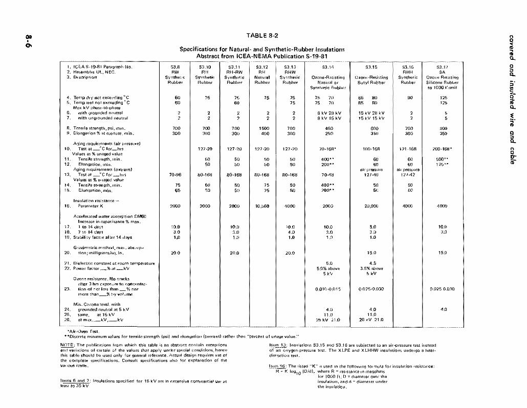

covered and insulated wire and cable
TABLE 8-4
Specifications for Cross-Linked Thermosetting Polyethylene and Ethylene-Propylene Rubber Insulations
Abstract from ICEA-NEMA Standards Publications S-66-524 and S-68-516
1 ICEA S-66-524 Paragraph No
2 ICEA S-68-516 Paragraph No
3 Resembles UL NEC
4 Description
5 Temp dry not exceeding degc 6 Temp wet not exceeding degc
Max kV phase-to-phase 7 8
with grounded neutral
with ungrounded neutral
9 Tensile strength psi min 10 Elongation at rupture min
Aging requirements (air-oven) 11 Test at_DC for_hrs
12 13
Values as unaged value
Tensile strength min Elongation min
14 Insulation resistance - Parameter K
Accelerated water absorption EM60 increase in capacitance max
15 1 to 14 days 16 7 to 14 days 17 Stability factor after 14 days
Gravimetric method max absorption 18 milligramssq in
19 Dielectric constant at room temp 20 Power factor_ at_kV
Min Corona Level with
21 grounded neutral at 5 kV 22 same at 15 kV 23 _same_max kV_kV
36
XLPE
Cross-Linked Thermosetting Polyethylene
90 90
35 25
800 250
121-168
75 75
10000
30 15 10
35 20
37
XHHWamp USE
Cross-Linked Thermosetting Polyethylene
90 90
2 2
1800 250
121-168
75 75
20000
30 15 10
60 20 above
5kV
40 110
35 kV-260
36
EPR
Ozone Resisting Ethylene
Propylene Rubber
90 90
35 25
700 250
121-168
75 75
20000
30 15 10
100
40 above 5kV
40 110
35 kV-260
See also AEIC-5 for XLPE primary cables and AEIC-6 for EPR primary cables
8-8
Thermoplastic Insulating Materials Unlike thermosetting compounds thermoplastic insulashy
tions remain plastic regardless of temperature and conseshyquently will soften or melt at temperatures that would not significantly affect thermosetting insulations The principal thermoplastic materials used for insulations have a resishynous base classified as polyvinyl chlorides and polyshyethylenes (not cross-linked) No vulcanization is required although ingredients are added to the mixture for quality control and to facilitate extrusion on the conductor
Thermoplastic Polyvinyl Chloride (PVC) This compound is not a synthetic rubber Basically it is a
resin of high molecular weight polyvinyl chloride or the copolymer of vinyl chloride and vinyl acetate Plasticizers stabilizers fillers and lubricants are added to meet apshyplication conditions PVC is often used for insulation and jackets particularly in oil or petroleum environments PVC loses from a third tgt half its hardness at 100degC and melts at about 140degC For some of its other physical and its electrical properties see Table 8-3
PVC insulating compounds are available for Type TW (NEC) insulation rated 60degC wet and dry fOr Type THW rated 75degC wet and dry for THHN rated 90degC dry and for higher temperatures as appliance wire consideration of which is beyond the scope of this book
Thermoplastic Polyethylene (PE) This material in its low density high-molecular weight
grade is used as the base from which thermosetting crossshylinked polyethylene is made as previously described Polyshyethylene of the same grade without cross-linking is specishyfied by ICEA as suitable for insulation of conductors for rated voltages to 35 kV for up to 75degC in dry Or wet locashytions This PE grade is subject to the ill-effects of ultrashyviolet lijiht (sunshine exposure) which can be corrected by jacketing with a similar material containing not less than 2 carbon black (PE-Black) or if not over 5 kV the pigment may be incorporated in the insulation
Polyethylene can be treated with chloro-sulphonic acid reSUlting in Hypawn which can be compounded in a manshyner similar to rubber Its electrical and moisture-resisting properties do not equal those of untreated PE but the aging characteristics are excellent
There are numerous grades and classifications of polyshyethylenes only a few of which are suitable for insuiations Table 8-3 lists the properties obtainable from Type I high molecular weight low-density polyethylene
The high-density low-molecular-weight polyethylene (black) is a compound used for insulation and covshyering on secondary line wire and service drops because of its exceilent resistance to abrasion The effect of reshypeated rubbing of tree branches and leaves that often surshyround such conductors is greatly reduced as is the cost of tree trimming
insulation and related cable components
Jacket Materials As has been stated often the most suitable insulation
for resisting dielectric stress may not have an outer surface that is suitable for the conditions which the cable must meet in service Thus for improvement in resistance to flame oil abrasion and chemical environment a suitable jacket is extruded around the insulated conductor Though the jacket may have moderate insulating quality its princishypal function is to protect the underlying cable components
Because one side of the jacket is at ambient temperature and the other is one the outside of the insulation the rated temperature for the jacket materials can be somewhat less than that of the insulation For this reason jackets may be of thermoplastic material Table 8-5 lists jacket properties according to ICEA
Polyvinyl Chloride lackels
The compound for polyvinyl chloride jackets closely reshysembles that used for PVC-60 insulation (S37 of Table 8-3) It is used for jacketing single- and muiti-conductor cables particularly when shielded These jackets provide toughness resistance to moisture and oil and have good low-temperature properties As regularly supplied they withstand reel bending at installation temperatures of -lOoC and if specially compounded as for mine cable are suitable under oil conditions in the range -10degC to 90degC Cables with PVC jackets are suitable for installation in conduit trough or tray underground ducts direct-earth burial and overhead on messengers
Polyethylene lackets
Black low-molecular weight (high-density) and highshymolecular weight (low-density) polyethylenes are frequentshyly used as jacketing material The 2 percent black pigment prevents deterioration from ultra-violet rays of sunlight PE jackets have specific application where extreme resistance to moisture and abrasion is required
Neoprene lackets Neoprene is a polymer of chloroprene containing about
38 of chlorine which accounts for its excellent flame and oil resistance It has comparatively high moisture abshysorption which with only moderate dielectric properties limits its use mostly for jackets Though oil resistant oil will pass through the material hence cable components under a neoprene jacket also must be oil resistant if that quality is required The properties of general-purpose neoprene and typical heavy-duty neoprene are listed in Table 8-5 General-purpose neoprene jackets are suitable for use On low-voltage cable or on high-voltage shielded cable when Ozone resistance is not required It is generaUy resistant to mechanical abuse Qils water chemicals and flame The heavy-duty neoprene jackets may be forshymulated to meet several conditions either singly or in comshybination thus extra protection against mechanical
8-9
covered and insulated wire and cable
damage water chemicals or flame extra-heavy duty for portable cables arctic type for extremely low temperatures and heat-resistant type for high temperatures
Nylon Jackets Nylon is a generic term for polyamide polymers This
material is a tough abrasion-resistant thermoplastic which can be extruded as a thin protective covering over PVC or PE insulation thereby improving its ability to withshystand damage to insulation from mechanical abrasion and cold flow Because of its poor electrical properties nylon is not used by itself as insulation
Nylon jackets are specified for several of the thermoshyplastic insulations listed in NEC thereby enabling thinner insulation to be used with resulting reduction of size of conduit and it is also used on control wire and similar constructions
Nitrile-ButadienePolyvinyl-Chloride Jackets This jacket consists of a vulcanized acrylonitrile-butashy
dienepolyvinyl-chloride compound based on a fluxed blend of acrylonitrile-butadiene synthetic rubber and polyshyvinyl-chloride resin It is made in two forms general-purshypose and heavy duty the latter having higher tensile strength and greater elongation at rupture (its tensile strength at 200 percent elongation is 500 psi) hence well suited where bending is a requirement as in portable cables
uUnipass Jackets
This construction is obtained merely by increasing the thickness of the insulation which is extruded by a single pass By virtue of the inherent toughness of the insulation surface a nominal increase of the insulation thickness over what is required for the voltage rating is regarded as the equivalent of a separate jacket This process is only suitshyable if the insulation surface is satisfactory to meet inshystallation conditions
No Jacket Requirements In this category are the single-conductor NEC Types TW
and THW and the RHW-RHH and XHHW cross-linked polyethylene insulated cables These cables have no jacket over the insulation and the insulation is not increased in thickness because of lack of jacket The normal insulation surface is considered sufficiently tough to resist normal conditions Some of these conductors however require inshystallation in conduit duct or on rigid supports to meet NEC requirements
Tapes and Shielding Materials
As outlined on page 8-1 the materials required to comshyplete a cable other than conductor inSUlation and jacket depend on kV rating and whether or not the cable is to have conductor shielding and insulation shielding
Insulating Tapes Insulating tapes of various kinds are sometimes used in
the assembly of single- or multi-conductor cables and they also are used for insulation at spikes and terminals The desired requirements for a tape suitable for the insulashytion body of a splice or terminal are as follows (I) dielecshytric constant not over 32 (2) can be stretched to just short of its breaking point during application and (3) bas a shelf life before use of at least 5 years without loss of quality Polyvinyl chloride tape of lesser insulation quality (dielecshytric constant up to 100) but well suited for exterior use is also used as a covering over the main insulation body of splices and terminals Semi-conducting and metallic tapes also are used for shielding and for splicing the shielding Care must be taken to ensure that the tape is compatible with the components on which it is placed
Shielding Materials and Shielding Methods
Insulation shields consist of metallic non-magnetic tape braid wires or sheaths A fibrous or other nonmetallic covering either conducting or non-conducting is applied over the insulation An additional covering may be applied over the first one if the finlt is conducting the outer one also must be conducting Metal-tape shields must be elecshytrically continuous Similar insulation shielding may be of metal braid Or of concentric round wires
Shielding of multiple-conductor cables is applied over the insulation of the individual conductors except that if the shielding is only for the purpose of reducing shock it may be applied over the whole conductor assembly For singie-conductor cable the shielding effect of tubular corshyrugated or interlocked armor is supplemented by auxiiiary nonmetallic shielding in intimate contact with the insulashytion and the metallic outer covering or sheath A separate metallic shield is not required However when an insushylating tape is bonded to the insulation the tape is conshysidered to be a part of the insulation and the auxiliary nonmetallic shield should be applied directly over the inshysulating tape
Insulation shielding is sometimes used as part of a cirshycuit for relaying or for locating fault position Considerashytion of such uses are beyond the scope of this book as is description of the conditions under which the shield is open-circuited short-circuited and grounded
Conductor shieldS consist of conducting nonmetallic tape extruded compound or cement They are applied over the surface of the conductor
The various thicknesses of both insulation and conducshytor shields are specified by ICBA for the various types of cables and applications
The Effect of Corona on Insulation and Shielding
As described in Chapter 3 whenever air is stressed electrically beyond its breakdown point the air will ionize
8-10
insulation and relaled cable components
TABLE 8-5
Specifications for Rubber Or Thermoplastic Jackets for Insulated Conductors and Cables Abstract from ICEA-NEMA Publication S-19-81-WC-3
i leEA S-19-81 Paragfaph No
2 Description
3 Minimum temperampure for cold weather appiea tions
4 Tensile strength psi min 5 Elongation at rupture min
Aging requirements ( air~oven)
6 Test at c for hr
Values as Unltliged v alue 7 Tensile strength min B Elongation min
Aging requirements ( oxygen pressure) 9 Test at QC fOT hIs
Values as unaged value 10 Tensile strength min 11 Elongationmin
12 Oil immersion at degc for hr
Values as unaged v alue
5413554132 I 84123 I S4134 1
I
I 13 Tensile strength min 60I 14 Elongation min 60
Neoprene
General
Purpose
Black amp Polyvinyl
Colors Chloride
-10C
1500 1500 250 100
100-lt8 100-5 days
85 50 50
60
54136
POlyshy
ethylene Black
-40C
1400 350
100-48
75 75
5413854137
Nitrile Nitrile
Butadiene Butadiene
PVC- PVC-
Brack amp Blackamp
Colors ColorsI Heavy General
PlIrposeOlltY
-2Sgte-25e
1800 1500 500 250
100-68 100-pound8
50 50 50 50
I 121-18 70-4 121-18 121-18
60 80 I I
60 60
60 60 60 60
54139
Chloro-
Sulph~
onate Poly-
Ethylene
Heavy
Dutyi
Synthetic
Rubber
5BR
1800 300
70-168
1600
Neoprene
Heavy
Duty Black
1800 300
100-lt8
50
I 60
1
Because the temperature gradientthrough insulation and jacket during operation assures a comparatively coo jacket the minimum air temperature at which jacket cracking will not oltcur is listed
Dlscrete minimum values for tensile strength psi) and elongation (percent) rather than percent of unaged value
Appficable to materials having a nominal thickness of 0030 in and up See also NOTE on Table 8~2
NOTE The airN 3ging tests for neoprene ~ackets for portable cables are based on 70e for 168 hrs instead of 127C for 20 hrs The oxygen test fOr 54135 is omitted but an oil-immersion test is made
NOTE Some of these jacket materials also are used as weatherproof semi~insulation coverings where conductor rating does not exceed 600 volts phases-to-Phase
1800 300
100-68
85
65
121-18
60
250 50i
70-96
1600 250
121-18 I
8-11
covered and insulated wire and cable
with the emission of ozone The visible manifestation of this ionization is corona the characteristic bluish glow that sometimes can be seen at night along bare overhead highvoJtage transmission lines It is not only necessary that the insulation have suitable resistance to the chemical action of ozone but it also must withstand the tendency for burning that may occur as a result of corona~discharge current
Coronadischarge eflects are greatest in voids in the inshysulation or between conductor and insulation Or shielding A corona-level test determines the absence of such voids that can cause local deterioration of the insulation proshyvided the actual operating voltage is less than the rated corona-level voltage
The coronalevel values listed in Tables 8-2 8-3 and 8-4 are to be considered in relation to phasetoground voltage Thus for insulation described in Col S3IS of Table 8-2 a cable used in a threephase 15 kV circuit has line-toshyneutral voltage of 150173 = 87 kV The corona-level requirement is listed as IIOkVhenceinsulation thickness that meets this requirement is suitable provided it is satisfactory otherwise
The strand and insulation shields are so designed as to prevent ionization between the inner surface of the insulashytion and the conductor and its outer surface and the metallic insulation shield A simpler form of insulation shielding is provided by the use of concentrically applied wires for potential-gradient control
Sheaths Fillers and Binders The various kinds of metal-clad armored or sheathshy
enclosed cables are described in other chapters Additional details as to the sheath materials as well as fillers and binders overall jacketing etc are in ICEA and NEC publications
ICEA Performance Specifications As previously mentioned insulation and related mashy
terials for cables are specified according to performance inshystead of by composition and processing An abstract of the principal performance values applying to commercial insulations is in Tables 8-2 8-3 and 8-4 which with the explanatory footnotes provide data as a guide to insulation selection Similar information applying to jacket materials is in Table 8-5 Several early-type insulations stiD are listed in the ICEA publication from whlch Table 82 was compilshyed but they are purposely omitted from Table 8-2 because they are obsolete
The following explanation of some of the terms used in the tables may aid their use Further details are in the referenced ICEA publications
Insulation Resistance (K (item 6) and formula in note to Table 82)
The insulation resistance is obtained in megohms for a cable 1000 it long measured after one-minutes applicashy
8middot12
tion of constant dc potential As the resistance is meashysured through the insulation to the outer surface the elements of current are in parallel hence the insulation resistance will be one-half as much for a cable length of 2000 ft Or ten times as much for a cable 100 ft long The test to determine one-minute dc insulation resistance by use of an immersed cable is at 156degC and made after a constant dc potential has been applied for one minute The ICEA standards contain adjustment factors for other temperatures This one-minute de value of insulation resistance principally is used for rough comparison of insulation quality and it is far from accurate because tests at other times than one minute may show wide differences and under ac conditions a different value is obtained See Appendix 8A for further discussion of insulation resistance R lac) under aC conditions
Waler Absorption By use of the electric method the increase in capacishy
tance ahove tbat of a dried block of insulating material when it is immersed and subjected to 60 Hz (EM 60 test) is an indication of the water absorption as compared with results of similar tests on other insulations By use of the gravimetric method the actual increase in weight of the dried specimen of standard size after immersion for a specified time is divided by the total surface area of the specimen
Temperature Tables 8-2 8-3 and 8-4 list only tbe maximum
temperature for normal operation Because of occasional operation at a higher temperature (emergency-overload conditions) or for an extremely short time (short-ltircuit conditions) additional data from the ICEA standards is supplied for some of the insulations in Table 9-7
NEC Designations The following summary of the most commonly used
NEC letter-designations used for describing insulations and cable constructions may be helpful for understanding specifications that include NEC abbreviations This sumshymary relates only to power cables of the usual kinds There are limitations and exceptions so the abbreviations must be used with caution Refer to NEC for full information
Insulation Materials
R = Rubber (natural or synthetic) T = Thermoplastic usually flame-retardant polyvinyl
chloride or polyethylene However TA and TBS are not flame retardant though can be made so by suitable outer covering
X = Cross-linked thermosetting polyethylene as used XHHW
FEP =Fluorinated ethylene propylene
insulation and related cable components
Heat-Resistant Quality
Without H = Usually suitable for 60C H = Usually suitable for 75C HH Usually suitable for 90C (except XHHW only
when dry)
Moisture and Oil-Resistant Quality
Without W = Usually suitable for dry locations W = Usually suitable for wet and dry locations M = Usually suitable for oily conditions (machine-tool
circuits) Do not confuse with M for metal as part of MC (metal-dad) for instance
Jackets and Sheaths (as part of a single conductor)
Note NEC does not use abbreviations for several jacketing materials (see Table 8-5)
]I Nylon
BS Fibrous braid
B = Glass mica or asbestos braid
L = Lead sheath
NEC Cable Constructions
MC Metal-clad with interlocking armor or close-fitshyting corrugated tube
AC Armor-clad with flexible metal tape
ACL Same as AC but with lead sheath
ACT Same as AC but the moisture-resistant fibrous covering need only be on the idividual conductors
NM Nonmetallic sheathed cable
NMC Same as NM but must be fungus and corrosion resistant
SE Service-entrance cable (also suitable for interior wiring under certain conditions) Not suitable for direct burial
USE Underground service entrance cable also suitshyable for direct burial
UF Underground feeder cable also suitable for direct burial under certain conditions
Insulating Compounds designated by NEC symbols
If the symbol contains R the compound is principally synthetic or natural rubber if it contains T it is a thermoplastic material if it contains X it is a crossshylinked thermosetting material Other letters are as previously indicated eg N indicates nylon jacketing
RW or TW for dry or wet locations at 60degC RH for dry locations at 75C RHH Or THHN for dry locations at 90C RHW THW or THWN for dry or wet locations at 75C XHHW for dry locations at 90degC and wet at 75C
APPENDIX 8A
Elements of Dielectric Theory
This appendix contains information that is generally understood by electrical engineers but it may be helpful as a reference to some of the terms used in the tables and as the basis for calculation of charging current
Dielectric Constant () Also designated specific inductive capacity (k) relative permittivity and similar terms
For a vacuum = I and for air it is 10006 hence for engineering calculations the difference is neglected The dielectric constant laquo) of a substance is the ratio of the capacitance of a condenser with the substance as the dielecshytric to the capacitance of the condenser with air as the dielectric
Thus an insulator with a large lt acquires a greater charge of electricity in coulombs Q for a given potential difference between its faces than will an insulator with a small The capacitance C of an insulator usually measshyured in microfarads is thus proportional to lt provided
conditions of temperature time dryness and applied voltshyage are the same A low lt is an apparent indication of superior insulation qUality However a low lt when dry may be much increased because of water absorption or other factors and such variations are different in various materials
Charging Current and Leakage-Conduclion Current It is convenient to consider the current input into an
insulator after voltage is applied as being in two parts (I) a charging (or displacement) current Ic that serves to inshycrease the potential of the insulator by accumulating a quantity of electricity (coulombs Q) in the body of the insulator and (2) a leakage-conduction current ie in phase with the applied voltage that supplies energy to heat the insulator (hecause of it internal dielectric stresses) and to supply the energy losses associated with the current that passes through the insulator or across its sudace
8-13
covered and insvlated wire and cable
The charging current Ic does not represent energy loss because after withdrawal of the voltage an equal current is discharged from the dielectric The leakage-conduction current Ie represents energy loss Ele or as indicated by the relationship R = Ell in which R is the insulation resistance as usually measured according to lCEA stanshydard assuming standard conditions (see page 8-12) of Chapter 8 and Tables 8-2 through 8-5) The insulation resistance varies through a wide range depending on the dielectric and temperature as shown by Table 8A-I which is an abstract of Table 6-21 of lCEA Standard S-19-81
Charging and Leakage-Conduction CurrentS Under Direct and A temating Potential
Because insulation resistance is found by test under continuous application of potential (for one minute acshycording to ICEA standard) the rate of increase of charge Q within the insulator and the consequent rate of reduction of input current Ic will differ from what occurs when the emf is alternating as is the usual condition When a constant dc emf is applied an appreciable time is required for the insulation to acquire its full charge if its lt is greater than I For some insulations it may take a half hour or more for equilibrium to be achieved so no further charging current flows
When subjected to alternating potential however the insulator (dielectric) is being charged and discharged at short intervals (l I 120 sec at 60 Hz) Less than a full charge is acquired by the insulator at each voltage peak because the time is so short This effect under alternating potential is taken into account by the concept of Capacishytive Reactance X in ohms as follows
Xc = I I (2 f C) (Eq SA-l)
where f = frequency Hz C == capacitance in farads for the stated frequency
Many tables only show Xc The corresponding value of C is readily determined by inverting the above equation to C= 1 (2fXc)
The charging current Ic in amperes is as follows
E (to neUIngt)I = 2f C (Eq 8A-2)
Xc
where E = volts to neutral and the other terms are as previously defined In practice Jc is obtained from tables nomogram or formula in a similar manner as described in Chapter 3 for bare conductors
middotIt is important to distinguish between the insulation resistakce R measured at one minute after applying de potential according to the leBA test method and R(ocJ that reflects the reduced capacitance under ac conditions The latter value is a function of charging curtent Ie at the given frequency and insu~ation power f~ that is R(fIC= E1c x pf in wftich E is volts to neutral (see the next section and example at end of this Appendix)
The leakage-conduction current Ie may be calculated from data as to insulation resistance after correction for temperature or by multiplying the charging current by the power factor that often is listed as a property of the insulation
Total Dielectric Current and Power Factor Under aC Conditions
The charging current Ic depends on rate of change of applied voltage hence its peak occurs when the voltage is changing at its most rapid rate ie when the voltage is at zero point of its wave The leakage-conduction current leis in phase with voltage The two currents and voltage are shown vcctorially in Fig 8A-1 The resultant of Ic and Ie shown as I is slightly out of phase with Ic by angle 8 The power factor of the insulation is the ratio of Ie to Ie closely equal to tan Ii and it is usually expressed as a percent that is if Iellc is 0005 the power factor is usually designated as 05
- 2 bullThe total dielectric currentIl= (Ie + Iegt Usually Ie
is so small with reference to Ic that it is neglected and the charging current Ic is considered to be the total dielectric Current 1
Dielectric Constant () Under ac Conditions The calculation of dielectric constant hy measuring
capacitance under conditions of steadily applied constant potential is not practicable for insulated-conductor studies Instead the usual practice is to find the capacitance of a cable of specified size and length under ac potential of specified frequency and to compute the dielectric constant from the known relation that the capacitance of the air space occupied by the volume of insulation is 10 Then by geometry and suitable conversion of terms
Dielectric Constant () = 13 600 C 10g10 (Did)
where (Eq 8A-3) C = Capacity in microfarads of a 10-ft section of
cable at 60 Hz D = Diameter over the insulation in any units d = Diameter under the insulation in the same units
Capacitance of the cable also may be determined when frequency is 1000 Hz but it should be so stated
Capacitance of Insulated Aerial Cables The capacitance of an insulated Cable with ungrounded
sheath suspended in an overhead distribution line and well separated from the return conductor is practically the same as that of a bare conductor under the same conshyditions The slight increase in capacity of the insulation caused hy an lt greater than 10 extends through such a small distance (the thickness of the insulation) that it does not significantly affect the capacity (or the capacitive reactance Xc) between the condlltctors Hence the tables in Chapter 4 for shunt capacitive reactance may be used for both bare and insulated conductors suspended comshyparatively far apart
8-14
insulaion and related cable components
-Fig 8-AI Vectorial Relationship of Charging Current Ie Leakage-Conduction Current Ie and Total Dielectric Current I in an insulator in time-relationship with EMF vector E IeIe == tan ~ Power Factor
TABLE 8A-1
Typical Temperature Corrections for Insulation Resistance at 156degC (60Q F) for Otller Temperatures An Abstract of Table 6-21 of ICEA 8-19-81 (1980)
NOTE From insulation test report the ratio of insulation resistance at 61degF to its value at 60degF is noted thereby obtaining Coefficient for oF which is used to select which vertical column is used Thus assuming the Coefficient is 106 and insulation resistance at 15SoC is 133 X 1013 ohms for 1000 ft the resistance at 239
QC (75F) is 240 X 133 X 1013 =
319 X 1013 ohms for 1000 ft As the resistances for adjacent lengths are in parallel the resistance of a 2000 it length is one-half of that of 1000 ft and for 100ft is ten times as much
Temperatur Coefficient for 10
F
Fe CO 103 104 105 106 107 108 109 110 111 112
50 100 074 068 061 056 051 OA6 042 039 035 032
55 128 086 082 078 075 071 068 065 062 059 057
60 156 100 100 100 100 100 100 100 100 100 100
65 183 116 122 128 134 lAO 147 154 161 1S9 176
70 211 134 148 163 179 197 216 237 259 284 311
75 239 156 180 208 240 276 317 364 418 478 547
80 267 181 219 265 321 387 466 560 673 806 965 85 294 209 267 339 429 543 685 862 108 136 170
NOTE Linear interpolation in the vertical columns is satisfactory or a curve may be draw
8middot15
covered and insulated wire and cable
Capacitance of Insulated Conductors With Grounded Sheath or Directly Buried
Where the insulated conductor has a grounded sheath its capacitance is a function of diameter insulation thickshyness and dielectric constant of the insulating material n as follows
C = (000736 X lt)logbull (Did)
where (Eq8A-4)
C = Capacitance in ffarad per 1000 ft euror = Dielectric constant D = Outside diameter of insulated conductor d = Diameter of metallic conductor
An approximation of C for an insulated conductor withshyout metallic grounded sheath but contained within a grounded metallic duct may be obtained from the above equation if an average D is estimated and is reduced to take into account that of air is 10 applying to the space between the exterior of the conductor insulation and the metal duct
Example of Dielectric Computation
The previously stated principles are the basis of the folshylowing computation Given
A 40 AWG aluminum single conductor 19 strands 0528 diameter a semi-conducting tape strand shield and 0110 wall of cross-linked polyethylene insulation in meshytallic sheath in 3-phase circuit at 24 kV with grounded neutral 60 Hz For this cable the dielectric constant is 27 and power factor tan 8 is 01 or 10
Find
Capacitance microfarads per 1000 ft designated as C ac Resistance megohms for 1000 ft designated as R(ac) Charging current amperes per loooft designated as Ie Dielectric loss watts per 1000 ft
From Eq 8A-4
D = 0528 + 2 (0110) = 0748 in d = 0528 in Did = 1417 log 1417 = 01513 and substituting in Eq8A-4 C = (000736 X 27)01513 = 01313 farads per 1000 ft
The following relationship is also known Ian 8 = 001 = IPe = (E1Rae) I (2lT fC) = III (2 IT fC Rae) in which C is in farads
Substitutirg transposing and expressing 01313 pfarad as farads
R - I ac - 2lT X 60 x 01313 X 10-6 x 001
2 020000 ohms for 1000 ft (202 megohms)
E to neutral (volts) Charging current Ie = -------shy
11 (2f C (farads)
24_00---X2_-X--60_X--0_1_3_13_ = 00686 amp per 1000 it
3 X 1 000000
Watts loss 00686 X 2400 X OoI 0951
per conductor IE= _ --- shywatts3 per
1000 ft
8middot16

covered and insulated wire and cable
damage water chemicals or flame extra-heavy duty for portable cables arctic type for extremely low temperatures and heat-resistant type for high temperatures
Nylon Jackets Nylon is a generic term for polyamide polymers This
material is a tough abrasion-resistant thermoplastic which can be extruded as a thin protective covering over PVC or PE insulation thereby improving its ability to withshystand damage to insulation from mechanical abrasion and cold flow Because of its poor electrical properties nylon is not used by itself as insulation
Nylon jackets are specified for several of the thermoshyplastic insulations listed in NEC thereby enabling thinner insulation to be used with resulting reduction of size of conduit and it is also used on control wire and similar constructions
Nitrile-ButadienePolyvinyl-Chloride Jackets This jacket consists of a vulcanized acrylonitrile-butashy
dienepolyvinyl-chloride compound based on a fluxed blend of acrylonitrile-butadiene synthetic rubber and polyshyvinyl-chloride resin It is made in two forms general-purshypose and heavy duty the latter having higher tensile strength and greater elongation at rupture (its tensile strength at 200 percent elongation is 500 psi) hence well suited where bending is a requirement as in portable cables
uUnipass Jackets
This construction is obtained merely by increasing the thickness of the insulation which is extruded by a single pass By virtue of the inherent toughness of the insulation surface a nominal increase of the insulation thickness over what is required for the voltage rating is regarded as the equivalent of a separate jacket This process is only suitshyable if the insulation surface is satisfactory to meet inshystallation conditions
No Jacket Requirements In this category are the single-conductor NEC Types TW
and THW and the RHW-RHH and XHHW cross-linked polyethylene insulated cables These cables have no jacket over the insulation and the insulation is not increased in thickness because of lack of jacket The normal insulation surface is considered sufficiently tough to resist normal conditions Some of these conductors however require inshystallation in conduit duct or on rigid supports to meet NEC requirements
Tapes and Shielding Materials
As outlined on page 8-1 the materials required to comshyplete a cable other than conductor inSUlation and jacket depend on kV rating and whether or not the cable is to have conductor shielding and insulation shielding
Insulating Tapes Insulating tapes of various kinds are sometimes used in
the assembly of single- or multi-conductor cables and they also are used for insulation at spikes and terminals The desired requirements for a tape suitable for the insulashytion body of a splice or terminal are as follows (I) dielecshytric constant not over 32 (2) can be stretched to just short of its breaking point during application and (3) bas a shelf life before use of at least 5 years without loss of quality Polyvinyl chloride tape of lesser insulation quality (dielecshytric constant up to 100) but well suited for exterior use is also used as a covering over the main insulation body of splices and terminals Semi-conducting and metallic tapes also are used for shielding and for splicing the shielding Care must be taken to ensure that the tape is compatible with the components on which it is placed
Shielding Materials and Shielding Methods
Insulation shields consist of metallic non-magnetic tape braid wires or sheaths A fibrous or other nonmetallic covering either conducting or non-conducting is applied over the insulation An additional covering may be applied over the first one if the finlt is conducting the outer one also must be conducting Metal-tape shields must be elecshytrically continuous Similar insulation shielding may be of metal braid Or of concentric round wires
Shielding of multiple-conductor cables is applied over the insulation of the individual conductors except that if the shielding is only for the purpose of reducing shock it may be applied over the whole conductor assembly For singie-conductor cable the shielding effect of tubular corshyrugated or interlocked armor is supplemented by auxiiiary nonmetallic shielding in intimate contact with the insulashytion and the metallic outer covering or sheath A separate metallic shield is not required However when an insushylating tape is bonded to the insulation the tape is conshysidered to be a part of the insulation and the auxiliary nonmetallic shield should be applied directly over the inshysulating tape
Insulation shielding is sometimes used as part of a cirshycuit for relaying or for locating fault position Considerashytion of such uses are beyond the scope of this book as is description of the conditions under which the shield is open-circuited short-circuited and grounded
Conductor shieldS consist of conducting nonmetallic tape extruded compound or cement They are applied over the surface of the conductor
The various thicknesses of both insulation and conducshytor shields are specified by ICBA for the various types of cables and applications
The Effect of Corona on Insulation and Shielding
As described in Chapter 3 whenever air is stressed electrically beyond its breakdown point the air will ionize
8-10
insulation and relaled cable components
TABLE 8-5
Specifications for Rubber Or Thermoplastic Jackets for Insulated Conductors and Cables Abstract from ICEA-NEMA Publication S-19-81-WC-3
i leEA S-19-81 Paragfaph No
2 Description
3 Minimum temperampure for cold weather appiea tions
4 Tensile strength psi min 5 Elongation at rupture min
Aging requirements ( air~oven)
6 Test at c for hr
Values as Unltliged v alue 7 Tensile strength min B Elongation min
Aging requirements ( oxygen pressure) 9 Test at QC fOT hIs
Values as unaged value 10 Tensile strength min 11 Elongationmin
12 Oil immersion at degc for hr
Values as unaged v alue
5413554132 I 84123 I S4134 1
I
I 13 Tensile strength min 60I 14 Elongation min 60
Neoprene
General
Purpose
Black amp Polyvinyl
Colors Chloride
-10C
1500 1500 250 100
100-lt8 100-5 days
85 50 50
60
54136
POlyshy
ethylene Black
-40C
1400 350
100-48
75 75
5413854137
Nitrile Nitrile
Butadiene Butadiene
PVC- PVC-
Brack amp Blackamp
Colors ColorsI Heavy General
PlIrposeOlltY
-2Sgte-25e
1800 1500 500 250
100-68 100-pound8
50 50 50 50
I 121-18 70-4 121-18 121-18
60 80 I I
60 60
60 60 60 60
54139
Chloro-
Sulph~
onate Poly-
Ethylene
Heavy
Dutyi
Synthetic
Rubber
5BR
1800 300
70-168
1600
Neoprene
Heavy
Duty Black
1800 300
100-lt8
50
I 60
1
Because the temperature gradientthrough insulation and jacket during operation assures a comparatively coo jacket the minimum air temperature at which jacket cracking will not oltcur is listed
Dlscrete minimum values for tensile strength psi) and elongation (percent) rather than percent of unaged value
Appficable to materials having a nominal thickness of 0030 in and up See also NOTE on Table 8~2
NOTE The airN 3ging tests for neoprene ~ackets for portable cables are based on 70e for 168 hrs instead of 127C for 20 hrs The oxygen test fOr 54135 is omitted but an oil-immersion test is made
NOTE Some of these jacket materials also are used as weatherproof semi~insulation coverings where conductor rating does not exceed 600 volts phases-to-Phase
1800 300
100-68
85
65
121-18
60
250 50i
70-96
1600 250
121-18 I
8-11
covered and insulated wire and cable
with the emission of ozone The visible manifestation of this ionization is corona the characteristic bluish glow that sometimes can be seen at night along bare overhead highvoJtage transmission lines It is not only necessary that the insulation have suitable resistance to the chemical action of ozone but it also must withstand the tendency for burning that may occur as a result of corona~discharge current
Coronadischarge eflects are greatest in voids in the inshysulation or between conductor and insulation Or shielding A corona-level test determines the absence of such voids that can cause local deterioration of the insulation proshyvided the actual operating voltage is less than the rated corona-level voltage
The coronalevel values listed in Tables 8-2 8-3 and 8-4 are to be considered in relation to phasetoground voltage Thus for insulation described in Col S3IS of Table 8-2 a cable used in a threephase 15 kV circuit has line-toshyneutral voltage of 150173 = 87 kV The corona-level requirement is listed as IIOkVhenceinsulation thickness that meets this requirement is suitable provided it is satisfactory otherwise
The strand and insulation shields are so designed as to prevent ionization between the inner surface of the insulashytion and the conductor and its outer surface and the metallic insulation shield A simpler form of insulation shielding is provided by the use of concentrically applied wires for potential-gradient control
Sheaths Fillers and Binders The various kinds of metal-clad armored or sheathshy
enclosed cables are described in other chapters Additional details as to the sheath materials as well as fillers and binders overall jacketing etc are in ICEA and NEC publications
ICEA Performance Specifications As previously mentioned insulation and related mashy
terials for cables are specified according to performance inshystead of by composition and processing An abstract of the principal performance values applying to commercial insulations is in Tables 8-2 8-3 and 8-4 which with the explanatory footnotes provide data as a guide to insulation selection Similar information applying to jacket materials is in Table 8-5 Several early-type insulations stiD are listed in the ICEA publication from whlch Table 82 was compilshyed but they are purposely omitted from Table 8-2 because they are obsolete
The following explanation of some of the terms used in the tables may aid their use Further details are in the referenced ICEA publications
Insulation Resistance (K (item 6) and formula in note to Table 82)
The insulation resistance is obtained in megohms for a cable 1000 it long measured after one-minutes applicashy
8middot12
tion of constant dc potential As the resistance is meashysured through the insulation to the outer surface the elements of current are in parallel hence the insulation resistance will be one-half as much for a cable length of 2000 ft Or ten times as much for a cable 100 ft long The test to determine one-minute dc insulation resistance by use of an immersed cable is at 156degC and made after a constant dc potential has been applied for one minute The ICEA standards contain adjustment factors for other temperatures This one-minute de value of insulation resistance principally is used for rough comparison of insulation quality and it is far from accurate because tests at other times than one minute may show wide differences and under ac conditions a different value is obtained See Appendix 8A for further discussion of insulation resistance R lac) under aC conditions
Waler Absorption By use of the electric method the increase in capacishy
tance ahove tbat of a dried block of insulating material when it is immersed and subjected to 60 Hz (EM 60 test) is an indication of the water absorption as compared with results of similar tests on other insulations By use of the gravimetric method the actual increase in weight of the dried specimen of standard size after immersion for a specified time is divided by the total surface area of the specimen
Temperature Tables 8-2 8-3 and 8-4 list only tbe maximum
temperature for normal operation Because of occasional operation at a higher temperature (emergency-overload conditions) or for an extremely short time (short-ltircuit conditions) additional data from the ICEA standards is supplied for some of the insulations in Table 9-7
NEC Designations The following summary of the most commonly used
NEC letter-designations used for describing insulations and cable constructions may be helpful for understanding specifications that include NEC abbreviations This sumshymary relates only to power cables of the usual kinds There are limitations and exceptions so the abbreviations must be used with caution Refer to NEC for full information
Insulation Materials
R = Rubber (natural or synthetic) T = Thermoplastic usually flame-retardant polyvinyl
chloride or polyethylene However TA and TBS are not flame retardant though can be made so by suitable outer covering
X = Cross-linked thermosetting polyethylene as used XHHW
FEP =Fluorinated ethylene propylene
insulation and related cable components
Heat-Resistant Quality
Without H = Usually suitable for 60C H = Usually suitable for 75C HH Usually suitable for 90C (except XHHW only
when dry)
Moisture and Oil-Resistant Quality
Without W = Usually suitable for dry locations W = Usually suitable for wet and dry locations M = Usually suitable for oily conditions (machine-tool
circuits) Do not confuse with M for metal as part of MC (metal-dad) for instance
Jackets and Sheaths (as part of a single conductor)
Note NEC does not use abbreviations for several jacketing materials (see Table 8-5)
]I Nylon
BS Fibrous braid
B = Glass mica or asbestos braid
L = Lead sheath
NEC Cable Constructions
MC Metal-clad with interlocking armor or close-fitshyting corrugated tube
AC Armor-clad with flexible metal tape
ACL Same as AC but with lead sheath
ACT Same as AC but the moisture-resistant fibrous covering need only be on the idividual conductors
NM Nonmetallic sheathed cable
NMC Same as NM but must be fungus and corrosion resistant
SE Service-entrance cable (also suitable for interior wiring under certain conditions) Not suitable for direct burial
USE Underground service entrance cable also suitshyable for direct burial
UF Underground feeder cable also suitable for direct burial under certain conditions
Insulating Compounds designated by NEC symbols
If the symbol contains R the compound is principally synthetic or natural rubber if it contains T it is a thermoplastic material if it contains X it is a crossshylinked thermosetting material Other letters are as previously indicated eg N indicates nylon jacketing
RW or TW for dry or wet locations at 60degC RH for dry locations at 75C RHH Or THHN for dry locations at 90C RHW THW or THWN for dry or wet locations at 75C XHHW for dry locations at 90degC and wet at 75C
APPENDIX 8A
Elements of Dielectric Theory
This appendix contains information that is generally understood by electrical engineers but it may be helpful as a reference to some of the terms used in the tables and as the basis for calculation of charging current
Dielectric Constant () Also designated specific inductive capacity (k) relative permittivity and similar terms
For a vacuum = I and for air it is 10006 hence for engineering calculations the difference is neglected The dielectric constant laquo) of a substance is the ratio of the capacitance of a condenser with the substance as the dielecshytric to the capacitance of the condenser with air as the dielectric
Thus an insulator with a large lt acquires a greater charge of electricity in coulombs Q for a given potential difference between its faces than will an insulator with a small The capacitance C of an insulator usually measshyured in microfarads is thus proportional to lt provided
conditions of temperature time dryness and applied voltshyage are the same A low lt is an apparent indication of superior insulation qUality However a low lt when dry may be much increased because of water absorption or other factors and such variations are different in various materials
Charging Current and Leakage-Conduclion Current It is convenient to consider the current input into an
insulator after voltage is applied as being in two parts (I) a charging (or displacement) current Ic that serves to inshycrease the potential of the insulator by accumulating a quantity of electricity (coulombs Q) in the body of the insulator and (2) a leakage-conduction current ie in phase with the applied voltage that supplies energy to heat the insulator (hecause of it internal dielectric stresses) and to supply the energy losses associated with the current that passes through the insulator or across its sudace
8-13
covered and insvlated wire and cable
The charging current Ic does not represent energy loss because after withdrawal of the voltage an equal current is discharged from the dielectric The leakage-conduction current Ie represents energy loss Ele or as indicated by the relationship R = Ell in which R is the insulation resistance as usually measured according to lCEA stanshydard assuming standard conditions (see page 8-12) of Chapter 8 and Tables 8-2 through 8-5) The insulation resistance varies through a wide range depending on the dielectric and temperature as shown by Table 8A-I which is an abstract of Table 6-21 of lCEA Standard S-19-81
Charging and Leakage-Conduction CurrentS Under Direct and A temating Potential
Because insulation resistance is found by test under continuous application of potential (for one minute acshycording to ICEA standard) the rate of increase of charge Q within the insulator and the consequent rate of reduction of input current Ic will differ from what occurs when the emf is alternating as is the usual condition When a constant dc emf is applied an appreciable time is required for the insulation to acquire its full charge if its lt is greater than I For some insulations it may take a half hour or more for equilibrium to be achieved so no further charging current flows
When subjected to alternating potential however the insulator (dielectric) is being charged and discharged at short intervals (l I 120 sec at 60 Hz) Less than a full charge is acquired by the insulator at each voltage peak because the time is so short This effect under alternating potential is taken into account by the concept of Capacishytive Reactance X in ohms as follows
Xc = I I (2 f C) (Eq SA-l)
where f = frequency Hz C == capacitance in farads for the stated frequency
Many tables only show Xc The corresponding value of C is readily determined by inverting the above equation to C= 1 (2fXc)
The charging current Ic in amperes is as follows
E (to neUIngt)I = 2f C (Eq 8A-2)
Xc
where E = volts to neutral and the other terms are as previously defined In practice Jc is obtained from tables nomogram or formula in a similar manner as described in Chapter 3 for bare conductors
middotIt is important to distinguish between the insulation resistakce R measured at one minute after applying de potential according to the leBA test method and R(ocJ that reflects the reduced capacitance under ac conditions The latter value is a function of charging curtent Ie at the given frequency and insu~ation power f~ that is R(fIC= E1c x pf in wftich E is volts to neutral (see the next section and example at end of this Appendix)
The leakage-conduction current Ie may be calculated from data as to insulation resistance after correction for temperature or by multiplying the charging current by the power factor that often is listed as a property of the insulation
Total Dielectric Current and Power Factor Under aC Conditions
The charging current Ic depends on rate of change of applied voltage hence its peak occurs when the voltage is changing at its most rapid rate ie when the voltage is at zero point of its wave The leakage-conduction current leis in phase with voltage The two currents and voltage are shown vcctorially in Fig 8A-1 The resultant of Ic and Ie shown as I is slightly out of phase with Ic by angle 8 The power factor of the insulation is the ratio of Ie to Ie closely equal to tan Ii and it is usually expressed as a percent that is if Iellc is 0005 the power factor is usually designated as 05
- 2 bullThe total dielectric currentIl= (Ie + Iegt Usually Ie
is so small with reference to Ic that it is neglected and the charging current Ic is considered to be the total dielectric Current 1
Dielectric Constant () Under ac Conditions The calculation of dielectric constant hy measuring
capacitance under conditions of steadily applied constant potential is not practicable for insulated-conductor studies Instead the usual practice is to find the capacitance of a cable of specified size and length under ac potential of specified frequency and to compute the dielectric constant from the known relation that the capacitance of the air space occupied by the volume of insulation is 10 Then by geometry and suitable conversion of terms
Dielectric Constant () = 13 600 C 10g10 (Did)
where (Eq 8A-3) C = Capacity in microfarads of a 10-ft section of
cable at 60 Hz D = Diameter over the insulation in any units d = Diameter under the insulation in the same units
Capacitance of the cable also may be determined when frequency is 1000 Hz but it should be so stated
Capacitance of Insulated Aerial Cables The capacitance of an insulated Cable with ungrounded
sheath suspended in an overhead distribution line and well separated from the return conductor is practically the same as that of a bare conductor under the same conshyditions The slight increase in capacity of the insulation caused hy an lt greater than 10 extends through such a small distance (the thickness of the insulation) that it does not significantly affect the capacity (or the capacitive reactance Xc) between the condlltctors Hence the tables in Chapter 4 for shunt capacitive reactance may be used for both bare and insulated conductors suspended comshyparatively far apart
8-14
insulaion and related cable components
-Fig 8-AI Vectorial Relationship of Charging Current Ie Leakage-Conduction Current Ie and Total Dielectric Current I in an insulator in time-relationship with EMF vector E IeIe == tan ~ Power Factor
TABLE 8A-1
Typical Temperature Corrections for Insulation Resistance at 156degC (60Q F) for Otller Temperatures An Abstract of Table 6-21 of ICEA 8-19-81 (1980)
NOTE From insulation test report the ratio of insulation resistance at 61degF to its value at 60degF is noted thereby obtaining Coefficient for oF which is used to select which vertical column is used Thus assuming the Coefficient is 106 and insulation resistance at 15SoC is 133 X 1013 ohms for 1000 ft the resistance at 239
QC (75F) is 240 X 133 X 1013 =
319 X 1013 ohms for 1000 ft As the resistances for adjacent lengths are in parallel the resistance of a 2000 it length is one-half of that of 1000 ft and for 100ft is ten times as much
Temperatur Coefficient for 10
F
Fe CO 103 104 105 106 107 108 109 110 111 112
50 100 074 068 061 056 051 OA6 042 039 035 032
55 128 086 082 078 075 071 068 065 062 059 057
60 156 100 100 100 100 100 100 100 100 100 100
65 183 116 122 128 134 lAO 147 154 161 1S9 176
70 211 134 148 163 179 197 216 237 259 284 311
75 239 156 180 208 240 276 317 364 418 478 547
80 267 181 219 265 321 387 466 560 673 806 965 85 294 209 267 339 429 543 685 862 108 136 170
NOTE Linear interpolation in the vertical columns is satisfactory or a curve may be draw
8middot15
covered and insulated wire and cable
Capacitance of Insulated Conductors With Grounded Sheath or Directly Buried
Where the insulated conductor has a grounded sheath its capacitance is a function of diameter insulation thickshyness and dielectric constant of the insulating material n as follows
C = (000736 X lt)logbull (Did)
where (Eq8A-4)
C = Capacitance in ffarad per 1000 ft euror = Dielectric constant D = Outside diameter of insulated conductor d = Diameter of metallic conductor
An approximation of C for an insulated conductor withshyout metallic grounded sheath but contained within a grounded metallic duct may be obtained from the above equation if an average D is estimated and is reduced to take into account that of air is 10 applying to the space between the exterior of the conductor insulation and the metal duct
Example of Dielectric Computation
The previously stated principles are the basis of the folshylowing computation Given
A 40 AWG aluminum single conductor 19 strands 0528 diameter a semi-conducting tape strand shield and 0110 wall of cross-linked polyethylene insulation in meshytallic sheath in 3-phase circuit at 24 kV with grounded neutral 60 Hz For this cable the dielectric constant is 27 and power factor tan 8 is 01 or 10
Find
Capacitance microfarads per 1000 ft designated as C ac Resistance megohms for 1000 ft designated as R(ac) Charging current amperes per loooft designated as Ie Dielectric loss watts per 1000 ft
From Eq 8A-4
D = 0528 + 2 (0110) = 0748 in d = 0528 in Did = 1417 log 1417 = 01513 and substituting in Eq8A-4 C = (000736 X 27)01513 = 01313 farads per 1000 ft
The following relationship is also known Ian 8 = 001 = IPe = (E1Rae) I (2lT fC) = III (2 IT fC Rae) in which C is in farads
Substitutirg transposing and expressing 01313 pfarad as farads
R - I ac - 2lT X 60 x 01313 X 10-6 x 001
2 020000 ohms for 1000 ft (202 megohms)
E to neutral (volts) Charging current Ie = -------shy
11 (2f C (farads)
24_00---X2_-X--60_X--0_1_3_13_ = 00686 amp per 1000 it
3 X 1 000000
Watts loss 00686 X 2400 X OoI 0951
per conductor IE= _ --- shywatts3 per
1000 ft
8middot16
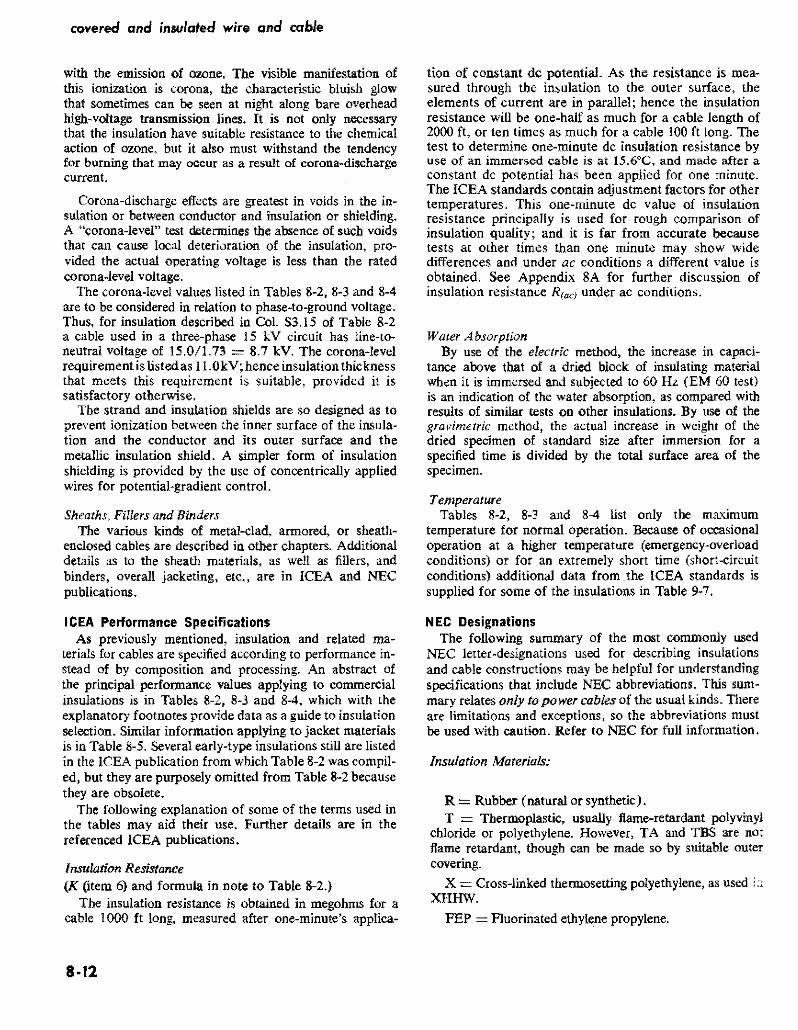
covered and insulated wire and cable
with the emission of ozone The visible manifestation of this ionization is corona the characteristic bluish glow that sometimes can be seen at night along bare overhead highvoJtage transmission lines It is not only necessary that the insulation have suitable resistance to the chemical action of ozone but it also must withstand the tendency for burning that may occur as a result of corona~discharge current
Coronadischarge eflects are greatest in voids in the inshysulation or between conductor and insulation Or shielding A corona-level test determines the absence of such voids that can cause local deterioration of the insulation proshyvided the actual operating voltage is less than the rated corona-level voltage
The coronalevel values listed in Tables 8-2 8-3 and 8-4 are to be considered in relation to phasetoground voltage Thus for insulation described in Col S3IS of Table 8-2 a cable used in a threephase 15 kV circuit has line-toshyneutral voltage of 150173 = 87 kV The corona-level requirement is listed as IIOkVhenceinsulation thickness that meets this requirement is suitable provided it is satisfactory otherwise
The strand and insulation shields are so designed as to prevent ionization between the inner surface of the insulashytion and the conductor and its outer surface and the metallic insulation shield A simpler form of insulation shielding is provided by the use of concentrically applied wires for potential-gradient control
Sheaths Fillers and Binders The various kinds of metal-clad armored or sheathshy
enclosed cables are described in other chapters Additional details as to the sheath materials as well as fillers and binders overall jacketing etc are in ICEA and NEC publications
ICEA Performance Specifications As previously mentioned insulation and related mashy
terials for cables are specified according to performance inshystead of by composition and processing An abstract of the principal performance values applying to commercial insulations is in Tables 8-2 8-3 and 8-4 which with the explanatory footnotes provide data as a guide to insulation selection Similar information applying to jacket materials is in Table 8-5 Several early-type insulations stiD are listed in the ICEA publication from whlch Table 82 was compilshyed but they are purposely omitted from Table 8-2 because they are obsolete
The following explanation of some of the terms used in the tables may aid their use Further details are in the referenced ICEA publications
Insulation Resistance (K (item 6) and formula in note to Table 82)
The insulation resistance is obtained in megohms for a cable 1000 it long measured after one-minutes applicashy
8middot12
tion of constant dc potential As the resistance is meashysured through the insulation to the outer surface the elements of current are in parallel hence the insulation resistance will be one-half as much for a cable length of 2000 ft Or ten times as much for a cable 100 ft long The test to determine one-minute dc insulation resistance by use of an immersed cable is at 156degC and made after a constant dc potential has been applied for one minute The ICEA standards contain adjustment factors for other temperatures This one-minute de value of insulation resistance principally is used for rough comparison of insulation quality and it is far from accurate because tests at other times than one minute may show wide differences and under ac conditions a different value is obtained See Appendix 8A for further discussion of insulation resistance R lac) under aC conditions
Waler Absorption By use of the electric method the increase in capacishy
tance ahove tbat of a dried block of insulating material when it is immersed and subjected to 60 Hz (EM 60 test) is an indication of the water absorption as compared with results of similar tests on other insulations By use of the gravimetric method the actual increase in weight of the dried specimen of standard size after immersion for a specified time is divided by the total surface area of the specimen
Temperature Tables 8-2 8-3 and 8-4 list only tbe maximum
temperature for normal operation Because of occasional operation at a higher temperature (emergency-overload conditions) or for an extremely short time (short-ltircuit conditions) additional data from the ICEA standards is supplied for some of the insulations in Table 9-7
NEC Designations The following summary of the most commonly used
NEC letter-designations used for describing insulations and cable constructions may be helpful for understanding specifications that include NEC abbreviations This sumshymary relates only to power cables of the usual kinds There are limitations and exceptions so the abbreviations must be used with caution Refer to NEC for full information
Insulation Materials
R = Rubber (natural or synthetic) T = Thermoplastic usually flame-retardant polyvinyl
chloride or polyethylene However TA and TBS are not flame retardant though can be made so by suitable outer covering
X = Cross-linked thermosetting polyethylene as used XHHW
FEP =Fluorinated ethylene propylene
insulation and related cable components
Heat-Resistant Quality
Without H = Usually suitable for 60C H = Usually suitable for 75C HH Usually suitable for 90C (except XHHW only
when dry)
Moisture and Oil-Resistant Quality
Without W = Usually suitable for dry locations W = Usually suitable for wet and dry locations M = Usually suitable for oily conditions (machine-tool
circuits) Do not confuse with M for metal as part of MC (metal-dad) for instance
Jackets and Sheaths (as part of a single conductor)
Note NEC does not use abbreviations for several jacketing materials (see Table 8-5)
]I Nylon
BS Fibrous braid
B = Glass mica or asbestos braid
L = Lead sheath
NEC Cable Constructions
MC Metal-clad with interlocking armor or close-fitshyting corrugated tube
AC Armor-clad with flexible metal tape
ACL Same as AC but with lead sheath
ACT Same as AC but the moisture-resistant fibrous covering need only be on the idividual conductors
NM Nonmetallic sheathed cable
NMC Same as NM but must be fungus and corrosion resistant
SE Service-entrance cable (also suitable for interior wiring under certain conditions) Not suitable for direct burial
USE Underground service entrance cable also suitshyable for direct burial
UF Underground feeder cable also suitable for direct burial under certain conditions
Insulating Compounds designated by NEC symbols
If the symbol contains R the compound is principally synthetic or natural rubber if it contains T it is a thermoplastic material if it contains X it is a crossshylinked thermosetting material Other letters are as previously indicated eg N indicates nylon jacketing
RW or TW for dry or wet locations at 60degC RH for dry locations at 75C RHH Or THHN for dry locations at 90C RHW THW or THWN for dry or wet locations at 75C XHHW for dry locations at 90degC and wet at 75C
APPENDIX 8A
Elements of Dielectric Theory
This appendix contains information that is generally understood by electrical engineers but it may be helpful as a reference to some of the terms used in the tables and as the basis for calculation of charging current
Dielectric Constant () Also designated specific inductive capacity (k) relative permittivity and similar terms
For a vacuum = I and for air it is 10006 hence for engineering calculations the difference is neglected The dielectric constant laquo) of a substance is the ratio of the capacitance of a condenser with the substance as the dielecshytric to the capacitance of the condenser with air as the dielectric
Thus an insulator with a large lt acquires a greater charge of electricity in coulombs Q for a given potential difference between its faces than will an insulator with a small The capacitance C of an insulator usually measshyured in microfarads is thus proportional to lt provided
conditions of temperature time dryness and applied voltshyage are the same A low lt is an apparent indication of superior insulation qUality However a low lt when dry may be much increased because of water absorption or other factors and such variations are different in various materials
Charging Current and Leakage-Conduclion Current It is convenient to consider the current input into an
insulator after voltage is applied as being in two parts (I) a charging (or displacement) current Ic that serves to inshycrease the potential of the insulator by accumulating a quantity of electricity (coulombs Q) in the body of the insulator and (2) a leakage-conduction current ie in phase with the applied voltage that supplies energy to heat the insulator (hecause of it internal dielectric stresses) and to supply the energy losses associated with the current that passes through the insulator or across its sudace
8-13
covered and insvlated wire and cable
The charging current Ic does not represent energy loss because after withdrawal of the voltage an equal current is discharged from the dielectric The leakage-conduction current Ie represents energy loss Ele or as indicated by the relationship R = Ell in which R is the insulation resistance as usually measured according to lCEA stanshydard assuming standard conditions (see page 8-12) of Chapter 8 and Tables 8-2 through 8-5) The insulation resistance varies through a wide range depending on the dielectric and temperature as shown by Table 8A-I which is an abstract of Table 6-21 of lCEA Standard S-19-81
Charging and Leakage-Conduction CurrentS Under Direct and A temating Potential
Because insulation resistance is found by test under continuous application of potential (for one minute acshycording to ICEA standard) the rate of increase of charge Q within the insulator and the consequent rate of reduction of input current Ic will differ from what occurs when the emf is alternating as is the usual condition When a constant dc emf is applied an appreciable time is required for the insulation to acquire its full charge if its lt is greater than I For some insulations it may take a half hour or more for equilibrium to be achieved so no further charging current flows
When subjected to alternating potential however the insulator (dielectric) is being charged and discharged at short intervals (l I 120 sec at 60 Hz) Less than a full charge is acquired by the insulator at each voltage peak because the time is so short This effect under alternating potential is taken into account by the concept of Capacishytive Reactance X in ohms as follows
Xc = I I (2 f C) (Eq SA-l)
where f = frequency Hz C == capacitance in farads for the stated frequency
Many tables only show Xc The corresponding value of C is readily determined by inverting the above equation to C= 1 (2fXc)
The charging current Ic in amperes is as follows
E (to neUIngt)I = 2f C (Eq 8A-2)
Xc
where E = volts to neutral and the other terms are as previously defined In practice Jc is obtained from tables nomogram or formula in a similar manner as described in Chapter 3 for bare conductors
middotIt is important to distinguish between the insulation resistakce R measured at one minute after applying de potential according to the leBA test method and R(ocJ that reflects the reduced capacitance under ac conditions The latter value is a function of charging curtent Ie at the given frequency and insu~ation power f~ that is R(fIC= E1c x pf in wftich E is volts to neutral (see the next section and example at end of this Appendix)
The leakage-conduction current Ie may be calculated from data as to insulation resistance after correction for temperature or by multiplying the charging current by the power factor that often is listed as a property of the insulation
Total Dielectric Current and Power Factor Under aC Conditions
The charging current Ic depends on rate of change of applied voltage hence its peak occurs when the voltage is changing at its most rapid rate ie when the voltage is at zero point of its wave The leakage-conduction current leis in phase with voltage The two currents and voltage are shown vcctorially in Fig 8A-1 The resultant of Ic and Ie shown as I is slightly out of phase with Ic by angle 8 The power factor of the insulation is the ratio of Ie to Ie closely equal to tan Ii and it is usually expressed as a percent that is if Iellc is 0005 the power factor is usually designated as 05
- 2 bullThe total dielectric currentIl= (Ie + Iegt Usually Ie
is so small with reference to Ic that it is neglected and the charging current Ic is considered to be the total dielectric Current 1
Dielectric Constant () Under ac Conditions The calculation of dielectric constant hy measuring
capacitance under conditions of steadily applied constant potential is not practicable for insulated-conductor studies Instead the usual practice is to find the capacitance of a cable of specified size and length under ac potential of specified frequency and to compute the dielectric constant from the known relation that the capacitance of the air space occupied by the volume of insulation is 10 Then by geometry and suitable conversion of terms
Dielectric Constant () = 13 600 C 10g10 (Did)
where (Eq 8A-3) C = Capacity in microfarads of a 10-ft section of
cable at 60 Hz D = Diameter over the insulation in any units d = Diameter under the insulation in the same units
Capacitance of the cable also may be determined when frequency is 1000 Hz but it should be so stated
Capacitance of Insulated Aerial Cables The capacitance of an insulated Cable with ungrounded
sheath suspended in an overhead distribution line and well separated from the return conductor is practically the same as that of a bare conductor under the same conshyditions The slight increase in capacity of the insulation caused hy an lt greater than 10 extends through such a small distance (the thickness of the insulation) that it does not significantly affect the capacity (or the capacitive reactance Xc) between the condlltctors Hence the tables in Chapter 4 for shunt capacitive reactance may be used for both bare and insulated conductors suspended comshyparatively far apart
8-14
insulaion and related cable components
-Fig 8-AI Vectorial Relationship of Charging Current Ie Leakage-Conduction Current Ie and Total Dielectric Current I in an insulator in time-relationship with EMF vector E IeIe == tan ~ Power Factor
TABLE 8A-1
Typical Temperature Corrections for Insulation Resistance at 156degC (60Q F) for Otller Temperatures An Abstract of Table 6-21 of ICEA 8-19-81 (1980)
NOTE From insulation test report the ratio of insulation resistance at 61degF to its value at 60degF is noted thereby obtaining Coefficient for oF which is used to select which vertical column is used Thus assuming the Coefficient is 106 and insulation resistance at 15SoC is 133 X 1013 ohms for 1000 ft the resistance at 239
QC (75F) is 240 X 133 X 1013 =
319 X 1013 ohms for 1000 ft As the resistances for adjacent lengths are in parallel the resistance of a 2000 it length is one-half of that of 1000 ft and for 100ft is ten times as much
Temperatur Coefficient for 10
F
Fe CO 103 104 105 106 107 108 109 110 111 112
50 100 074 068 061 056 051 OA6 042 039 035 032
55 128 086 082 078 075 071 068 065 062 059 057
60 156 100 100 100 100 100 100 100 100 100 100
65 183 116 122 128 134 lAO 147 154 161 1S9 176
70 211 134 148 163 179 197 216 237 259 284 311
75 239 156 180 208 240 276 317 364 418 478 547
80 267 181 219 265 321 387 466 560 673 806 965 85 294 209 267 339 429 543 685 862 108 136 170
NOTE Linear interpolation in the vertical columns is satisfactory or a curve may be draw
8middot15
covered and insulated wire and cable
Capacitance of Insulated Conductors With Grounded Sheath or Directly Buried
Where the insulated conductor has a grounded sheath its capacitance is a function of diameter insulation thickshyness and dielectric constant of the insulating material n as follows
C = (000736 X lt)logbull (Did)
where (Eq8A-4)
C = Capacitance in ffarad per 1000 ft euror = Dielectric constant D = Outside diameter of insulated conductor d = Diameter of metallic conductor
An approximation of C for an insulated conductor withshyout metallic grounded sheath but contained within a grounded metallic duct may be obtained from the above equation if an average D is estimated and is reduced to take into account that of air is 10 applying to the space between the exterior of the conductor insulation and the metal duct
Example of Dielectric Computation
The previously stated principles are the basis of the folshylowing computation Given
A 40 AWG aluminum single conductor 19 strands 0528 diameter a semi-conducting tape strand shield and 0110 wall of cross-linked polyethylene insulation in meshytallic sheath in 3-phase circuit at 24 kV with grounded neutral 60 Hz For this cable the dielectric constant is 27 and power factor tan 8 is 01 or 10
Find
Capacitance microfarads per 1000 ft designated as C ac Resistance megohms for 1000 ft designated as R(ac) Charging current amperes per loooft designated as Ie Dielectric loss watts per 1000 ft
From Eq 8A-4
D = 0528 + 2 (0110) = 0748 in d = 0528 in Did = 1417 log 1417 = 01513 and substituting in Eq8A-4 C = (000736 X 27)01513 = 01313 farads per 1000 ft
The following relationship is also known Ian 8 = 001 = IPe = (E1Rae) I (2lT fC) = III (2 IT fC Rae) in which C is in farads
Substitutirg transposing and expressing 01313 pfarad as farads
R - I ac - 2lT X 60 x 01313 X 10-6 x 001
2 020000 ohms for 1000 ft (202 megohms)
E to neutral (volts) Charging current Ie = -------shy
11 (2f C (farads)
24_00---X2_-X--60_X--0_1_3_13_ = 00686 amp per 1000 it
3 X 1 000000
Watts loss 00686 X 2400 X OoI 0951
per conductor IE= _ --- shywatts3 per
1000 ft
8middot16
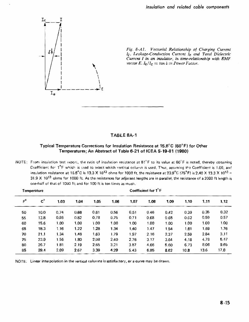
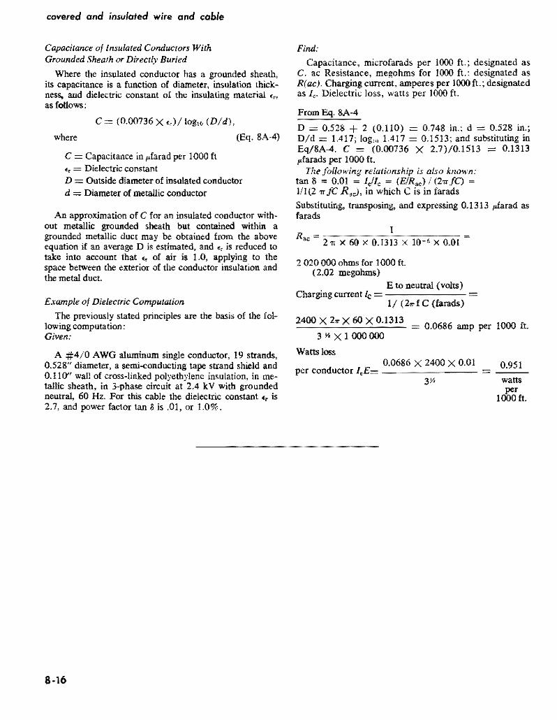