Embed Size (px)
Citation preview

INTAKE AND EXHAUST


INTAKE AND EXHAUST – Service Specifications/Sealant/On-vehicle Service15-2
SERVICE SPECIFICATIONS 15100030128
Items Standard value Limit
Waste gate actuator activation pressure kPa Approx. 83 –
Intake air temperature switch C OFF (no continuity) 55 or less –
ON (continuity) 57 or more –
Manifold distortion of the installation surface mm 0.15 or less 0.20
SEALANT 15100050025
Item Specified sealant Remark
Water outlet fitting <4G6> MITSUBISHI GENUINE PARTMD970389 or equivalent
Semi-drying sealant
ON-VEHICLE SERVICE 15100180137
INTAKE MANIFOLD VACUUM CHECK <4G6>Refer to GROUP 11A – On-vehicle Service
TURBOCHARGER SUPERCHARGING CHECK<4D56 with turbocharger> 15100100041
CautionConduct the driving test in a location where driving atfull acceleration can be done with safety. Two personshould be in the vehicle when the test is conducted; theperson in the passenger seat should read the indicationsshown by the pressure meter.
1. Remove the boost compensator hose from the fuelinjection pump, and install a pressure gauge as shownin the illustration.
2. Drive at full-throttle acceleration in second gear and thenmeasure the supercharging when the engine speed inabout 3,000 r/min.
3. When the indicated supercharging does not becomepositive pressure, check the following items. Malfunction of the waste gate actuator. Leakage of supercharging pressure. Malfunction of the turbocharger.
4. When the indicated supercharging is 84 kPa or more,supercharging control may be faulty, therefore check thefollowings. Disconnection or cracks of the waste gate actuator
rubber hose. Malfunction of the waste gate actuator. Malfunction of the waste gate valve.

INTAKE AND EXHAUST – On-vehicle Service 15-3
WASTE GATE ACTUATOR CHECK <4D56-withturbocharger> 15100120023
1. Connect a manual pump (pressure-application type) tonipple.
2. While gradually applying pressure, check the pressurethat begins to activate (approx. 1 mm stroke) the wastegate actuator rod.
Standard value: Approx. 83 kPa
CautionIn order to avoid damage to the diaphragm, do notapply a pressure of 91 kPa or higher.
3. If there is a significant deviation from the standard value,check the actuator or the waste gate valve: replace ifnecessary.
POWER RELAY CHECK 15100620011
INTERCOOLER FAN MOTOR RELAY CONTINUITY CHECK
Battery voltage Terminal No.
1 3 4 5
Power is not supplied
Power is supplied

INTAKE AND EXHAUST – Air Cleaner15-4
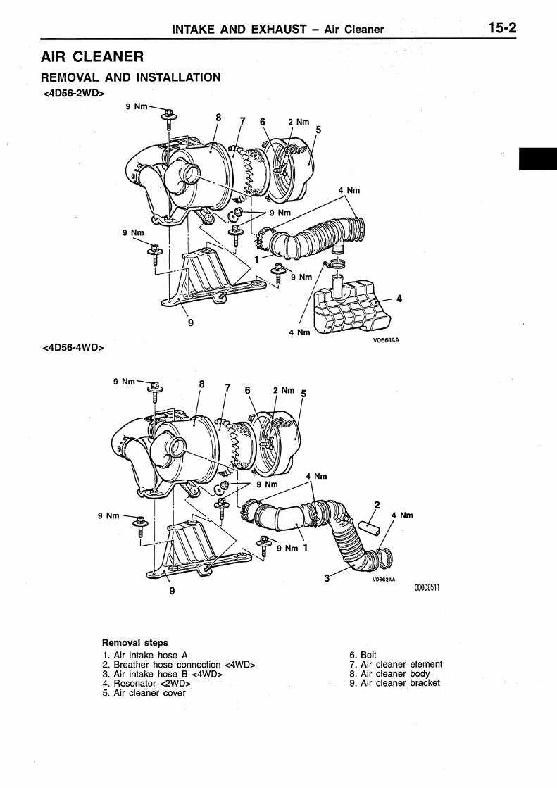
AIR CLEANER 15100210058
REMOVAL AND INSTALLATION
4 Nm
4 Nm
8
9 Nm
<4G63>
<4G64>
4 Nm
9 Nm
9 Nm 4 Nm
9 Nm
7 62
1
43
5 9
9 Nm
9 Nm
8
7 62
1
495
Removal steps1. Breather hose connection2. Air intake hose3. Resonator <4G63>4. Resonator5. Air duct
6. Air flow sensor assembly7. Air cleaner cover8. Air cleaner element9. Air cleaner body

INTAKE AND EXHAUST – Air Cleaner 15-5
9 Nm
9 Nm
89 Nm
2.0 Nm
<4D56-2WD>
<4D56-4WD>
4 Nm
7 6
3
4
9 Nm
9 Nm
9 Nm
4 Nm 4 Nm
4 Nm
4 Nm
4 Nm
4 Nm
2.0 Nm
2
19
8 7 6 5
2
319
5
Removal steps1. Air intake hose A2. Breather hose connection3. Air intake hose B4. Resonator <2WD>5. Air cleaner cover
6. Bolt7. Air cleaner element8. Air cleaner body9. Air cleaner bracket

INTAKE AND EXHAUST – Intercooler and Intercooler Fan-ECU15-6
INTERCOOLER AND INTERCOOLER FAN-ECU 15100420031
REMOVAL AND INSTALLATION
9 Nm
9 Nm
3
21
6
9
8
8
7
4
5
9 Nm
9 Nm
Intercooler fan-ECU removal steps1. Scuff plate2. Cowl side trim3. Intercooler fan-ECU
Intercooler removal steps4. Intake air temperature switch
connector5. Intercooler fan motor connector6. Air hose B connection (Intake
manifold side)7. Air hose A-2 connection (Turbochar-
ger side)8. Front bracket9. Intercooler and bracket assembly

INTAKE AND EXHAUST – Intercooler and Intercooler Fan-ECU 15-7
DISASSEMBLY AND REASSEMBLY 15100660013
9 Nm
6 Nm
6 Nm
1
5
2
98
7
10
46
3
9 Nm
Disassembly steps1. Air hose A-22. Blanch tube3. Blanch tube bracket4. Intercooler cover5. Air hose A-1
6. Air hose B7. Intake air temperature switch8. Intercooler bracket9. Fan and motor assembly
10. Intercooler
INSPECTION 15100430027
Check the intercooler fins for bending damage or foreignmatter.
Check the intercooler hoses for cracking, damage or wear.

INTAKE AND EXHAUST – Intercooler and Intercooler Fan-ECU15-8
INTAKE AIR TEMPERATURE SWITCH CHECK15100630014
1. Immerse the intake air temperature switch in the hot watershown in the figure.
2. When changing the water temperature, check forcontinuity between the terminals with the circuit tester.
Standard value:
Temperature Continuity
Less than 55 C(Temperature at point A)
OFF (No continuity)
More than 57 C(Temperature at point B)
ON (Continuity)
ON
OFFWatertemperature
B
A

INTAKE AND EXHAUST – Intake Manifold <4G6> 15-9
INTAKE MANIFOLD <4G6> 15100300274
REMOVAL AND INSTALLATION
Pre-removal Operation Fuel Discharge Prevention
(Refer to GROUP 13A – On-vehicle Service) Engine Coolant Draining Air Cleaner Removal (Refer to P. 15-4.) Battery and Battery Tray Removal
Post -installation Operation Engine Coolant Supplying Battery and Battery Tray Installation Air Cleaner Installation (Refer to P.15-4.)
20 Nm
14 Nm
O-ring
Sealant:MITSUBISHIGENUINE PARTMD970389 orequivalent
Engine Oil 5 Nm
12 Nm
20 Nm
22 Nm
64
1
8
6
2
3
75
13
10
4
11
12
3)
9
Removal steps1. Throttle body (Refer to GROUP
13A – Throttle Body.)2. PCV hose3. Brake booster vacuum hose
connection4. Water outlet fitting5. Vacuum hose connection
A 6. High-pressure fuel hose connection
7. Fuel return hose connection8. Injector connector
A 9. Injector and delivery pipe assembly10. EGR valve11. Intake manifold stay12. Intake manifold13. Intake manifold gasket
INTAKE AND EXHAUST – Intake Manifold <4G6>15-10
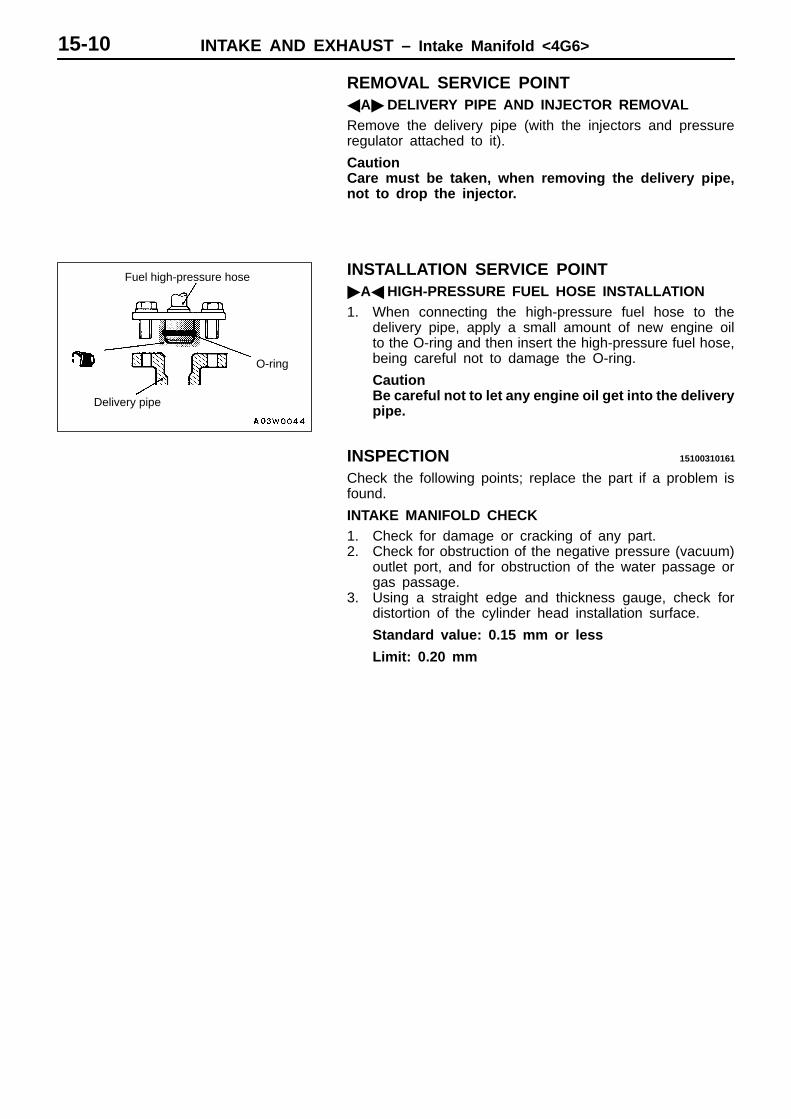
REMOVAL SERVICE POINTADELIVERY PIPE AND INJECTOR REMOVALRemove the delivery pipe (with the injectors and pressureregulator attached to it).
CautionCare must be taken, when removing the delivery pipe,not to drop the injector.
INSTALLATION SERVICE POINTAHIGH-PRESSURE FUEL HOSE INSTALLATION1. When connecting the high-pressure fuel hose to the
delivery pipe, apply a small amount of new engine oilto the O-ring and then insert the high-pressure fuel hose,being careful not to damage the O-ring.
CautionBe careful not to let any engine oil get into the deliverypipe.
INSPECTION 15100310161
Check the following points; replace the part if a problem isfound.
INTAKE MANIFOLD CHECK1. Check for damage or cracking of any part.2. Check for obstruction of the negative pressure (vacuum)
outlet port, and for obstruction of the water passage orgas passage.
3. Using a straight edge and thickness gauge, check fordistortion of the cylinder head installation surface.
Standard value: 0.15 mm or less
Limit: 0.20 mm
Fuel high-pressure hose
Delivery pipe
O-ring

INTAKE AND EXHAUST – Intake and ExhaustManifold <4D56-2WD> 15-11
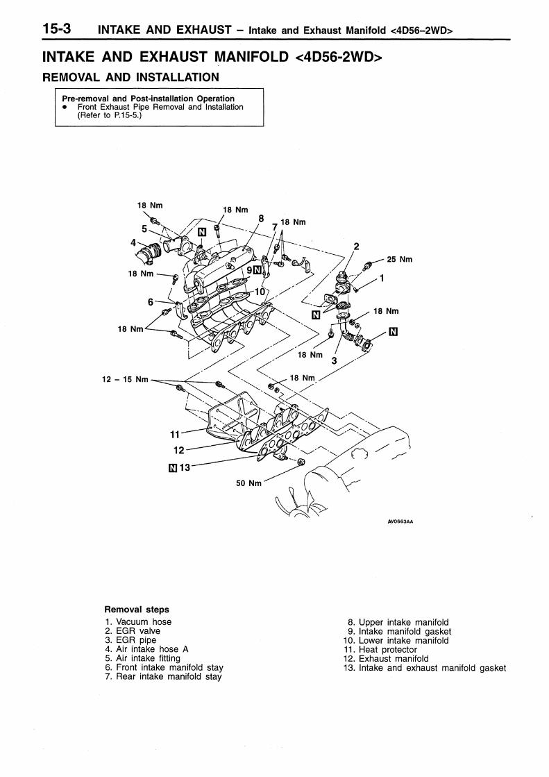
INTAKE AND EXHAUST MANIFOLD <4D56-2WD> 15100360029
REMOVAL AND INSTALLATION
Pre-removal and Post-installation Operation Front Exhaust Pipe Removal and Installation
(Refer to P.15-19.)
2
12 – 15 Nm
18 Nm
1
3
4
5
18 Nm
18 Nm
18 Nm
Removal steps1. Vacuum pipe attaching bolt2. Intake manifold3. Heat protector4. Exhaust manifold5. Intake and exhaust manifold gasket
INSPECTION 15100370022
Check the following points; replace the part if a problem isfound.
INTAKE AND EXHAUST MANIFOLD CHECK1. Check for damage or cracking of any part.2. Using a straight edge and thickness gauge, check for
distortion of the cylinder head installation surface.
Standard valve: 0.15 mm or less
Limit: 0.20 mm
INTAKE AND EXHAUST – Turbocharger and ExhaustManifold <4D56-4WD>15-12
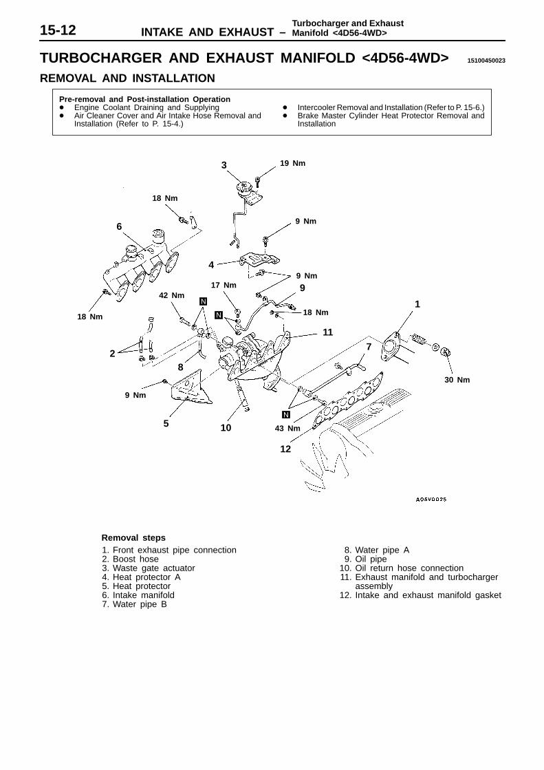
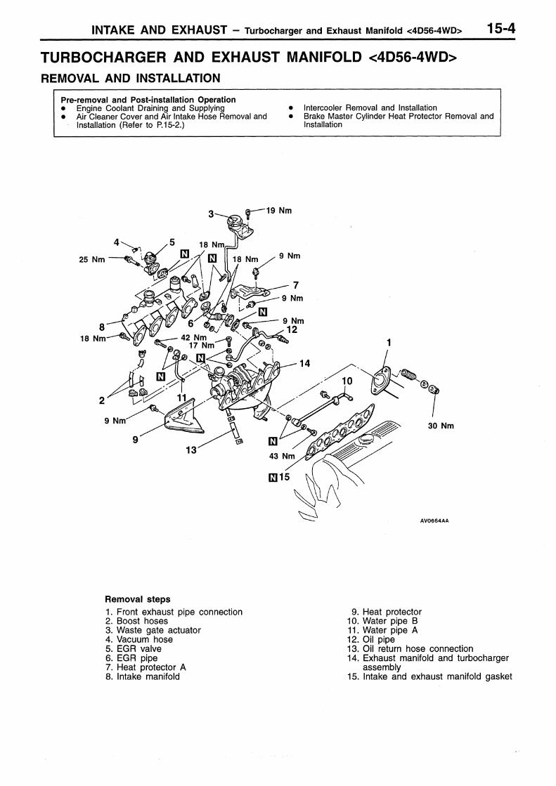
TURBOCHARGER AND EXHAUST MANIFOLD <4D56-4WD> 15100450023
REMOVAL AND INSTALLATION
Pre-removal and Post-installation Operation Engine Coolant Draining and Supplying Air Cleaner Cover and Air Intake Hose Removal and
Installation (Refer to P. 15-4.)
Intercooler Removal and Installation (Refer to P. 15-6.) Brake Master Cylinder Heat Protector Removal and
Installation
43 Nm
9 Nm
6
18 Nm
19 Nm
9 Nm
17 Nm42 Nm
30 Nm
4
2
5 10
12
117
1
3
9
18 Nm
9 Nm
18 Nm
8
Removal steps1. Front exhaust pipe connection2. Boost hose3. Waste gate actuator4. Heat protector A5. Heat protector6. Intake manifold7. Water pipe B
8. Water pipe A9. Oil pipe
10. Oil return hose connection11. Exhaust manifold and turbocharger
assembly12. Intake and exhaust manifold gasket

INTAKE AND EXHAUST – Turbocharger and ExhaustManifold <4D56-4WD> 15-13
60 Nm
14
9 Nm
60 Nm
12 – 15 Nm
19
16
18
13
1720
15
13. Exhaust fitting14. Exhaust fitting gasket15. Oil-return pipe16. Oil-return pipe gasket17. Exhaust manifold18. Turbocharger gasket
A 19. Turbocharger assembly20. Heat protector
INSTALLATION SERVICE POINTA TURBOCHARGER ASSEMBLY INSTALLATION1. Clean the alignment surfaces shown in the illustration.2. Supply clean engine oil from the oil pipe mounting hole
of the turbocharger assembly.
CautionWhen cleaning, take care that no foreign material getsinto the engine coolant or oil passages hole.
INSPECTION 15100640017
TURBOCHARGER ASSEMBLY CHECK Visually check the turbine wheel and the compressor
wheel for cracking or other damage. Check whether the turbine wheel and the compressor
wheel can be easily turned by hand. Check for oil leakage from the turbocharger assembly. Check whether or not the waste gate valve remains open.
If any problem is found, replace the part after disassembly.Compressorwheel

INTAKE AND EXHAUST – Turbocharger and ExhaustManifold <4D56-4WD>15-14
OIL PIPE AND OIL RETURN PIPE CHECK 15100650010
Check the oil pipe and oil return pipe for clogging, bending,or other damage. If there is clogging, clean it.
EXHAUST MANIFOLD CHECK 15100340108
Damage or cracking of any part.

INTAKE AND EXHAUST – Turbocharger 15-15
TURBOCHARGER 15100600015
DISASSEMBLY AND REASSEMBLY
2
5 Nm
6
5
4
3
1
Disassembly stepsE 1. CouplingD 2. Turbine housing
A C 3. Snap ringB B 4. Turbine wheel assembly
5. Compressor coverA 6. O-ring
DISASSEMBLY SERVICE POINTSASNAP RING REMOVALLay the unit with the compressor cover side facing downand using snap ring pliers, remove the compressor coverattaching snap ring.
CautionWhen removing the snap ring, hold it with fingers toprevent it from springing away.
Snap ring
INTAKE AND EXHAUST – Turbocharger15-16
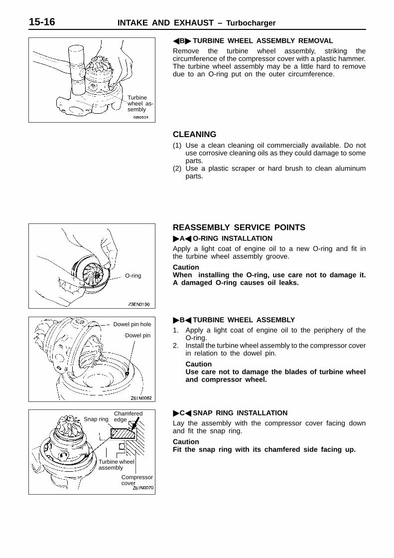
B TURBINE WHEEL ASSEMBLY REMOVALRemove the turbine wheel assembly, striking thecircumference of the compressor cover with a plastic hammer.The turbine wheel assembly may be a little hard to removedue to an O-ring put on the outer circumference.
CLEANING(1) Use a clean cleaning oil commercially available. Do not
use corrosive cleaning oils as they could damage to someparts.
(2) Use a plastic scraper or hard brush to clean aluminumparts.
REASSEMBLY SERVICE POINTSAO-RING INSTALLATIONApply a light coat of engine oil to a new O-ring and fit inthe turbine wheel assembly groove.
CautionWhen installing the O-ring, use care not to damage it.A damaged O-ring causes oil leaks.
B TURBINE WHEEL ASSEMBLY1. Apply a light coat of engine oil to the periphery of the
O-ring.2. Install the turbine wheel assembly to the compressor cover
in relation to the dowel pin.
CautionUse care not to damage the blades of turbine wheeland compressor wheel.
CSNAP RING INSTALLATIONLay the assembly with the compressor cover facing downand fit the snap ring.
CautionFit the snap ring with its chamfered side facing up.
Turbinewheel as-sembly
O-ring
Dowel pin hole
Dowel pin
Snap ringChamferededge
Turbine wheelassembly
Compressorcover

INTAKE AND EXHAUST – Turbocharger 15-17
D TURBINE HOUSING INSTALLATIONInstall the turbine housing in relation to the dowel pin.
CautionUse care not to damage the blades of turbine wheel.
E COUPLING INSTALLATIONInstall the coupling and tighten to specified torque.
INSPECTION 15100610018
TURBINE HOUSING1. Check the housing for traces of contact with the turbine
wheel, cracks due to overheating, pitching, deformationand other damage. Replace with a new turbine housingif cracked.
2. Operate the waste gate valve lever manually to checkthat the gate can be operated and closed smoothly.
COMPRESSOR COVERCheck the compressor cover for traces of contact with thecompressor wheel and other damage.
TURBINE WHEEL ASSEMBLY1. Check the turbine and compressor wheel blades for bend,
burr, damage, corrosion and traces of contact on theback side and replace if defective.
2. Check the oil passage of the turbine wheel assemblyfor deposit and clogging.
3. In the case of water cooled type, check also the waterpassage for deposit and clogging.
4. Check the turbine wheel and compressor wheel for lightand smooth turning.
OIL PIPE/OIL RETURN PIPECorrect or replace the oil pipe and oil return pipe if clogged,collapsed, deformed or otherwise damaged.
Dower pin hole
Dower pin
Coupling
Traces forcontact
Compressorwheel
Oil passage
Turbine wheel
Water passage
INTAKE AND EXHAUST – Exhaust Manifold <4G6>15-18
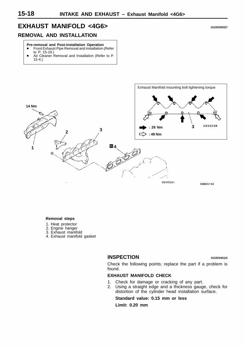
EXHAUST MANIFOLD <4G6> 15100330327
REMOVAL AND INSTALLATION
Pre-removal and Post-installation Operation Front Exhaust Pipe Removal and Installation (Refer
to P. 15-19.) Air Cleaner Removal and Installation (Refer to P.
15-4.)
14 Nm
1
Exhaust Manifold mounting bolt tightening torque
: 29 Nm
: 49 Nm2 3
4
3
Removal steps1. Heat protector2. Engine hanger3. Exhaust manifold4. Exhaust manifold gasket
INSPECTION 15100340115
Check the following points; replace the part if a problem isfound.
EXHAUST MANIFOLD CHECK1. Check for damage or cracking of any part.2. Using a straight edge and a thickness gauge, check for
distortion of the cylinder head installation surface.
Standard value: 0.15 mm or less
Limit: 0.20 mm

INTAKE AND EXHAUST – Exhaust Pipe and Main Muffler 15-19
EXHAUST PIPE AND MAIN MUFFLER 15100540249
REMOVAL AND INSTALLATION
Pre-removal and Post-installation Operation Front Under Cover Removal and Installation <2WD> Front Under Cover and Transfer Case Protector
Removal and Installation <4WD>
35 Nm
25 Nm
18
<4G63>
50 Nm
44 Nm
50 Nm
13 Nm25 Nm
12
16
10 1311 8 7
2
4 3
53
6
178
917
1514
13 Nm
3, 7, 14
Main muffler removal steps1. Bolt2. Main muffler3. Hanger4. Heat protector5. Hanger bracket6. Rear body floor heat protector
Main muffler removal steps1. Bolt7. Hanger8. Heat protector9. Center exhaust pipe
10. Nut11. Catalytic converter12. Front floor heat protector B
Front exhaust pipe removal steps10. Nut13. Oxygen sensor14. Hanger15. Heat protector16. Exhaust support bracket17. Front exhaust pipe18. Front floor heat protector A

INTAKE AND EXHAUST – Exhaust Pipe and Main Muffler15-20
25 Nm
17
<4D56>
50 Nm
48 Nm
13 Nm
<4G64>
11 3 5
34
2
110
91630 Nm
25 Nm
1117
1314
15
16 910
76
1 25 Nm67
12
44 Nm
50 Nm
3, 6, 13
6
25 Nm
25 Nm
8
13 Nm
Main muffler removal steps1. Bolt2. Main muffler3. Hanger4. Heat protector5. Hanger bracket
Center exhaust pipe removal steps1. Bolt6. Hanger7. Heat protector8. Center exhaust pipe9. Bolt <4D56> or nut <4G64>
10. Catalytic converter11. Front floor heat protector B
Front exhaust pipe removal steps9. Bolt <4D56> or nut <4G64>
12. Oxygen sensor13. Hanger14. Heat protector15. Exhaust support bracket16. Front exhaust pipe17. Front floor heat protector A


15-1
INTAKE ANDEXHAUST
CONTENTS
GENERAL 2. . . . . . . . . . . . . . . . . . . . . . . . . . . . . . . . . Outline of Changes 2. . . . . . . . . . . . . . . . . . . . . . . . . .
SPECIAL TOOL <4G64> 2. . . . . . . . . . . . . . . . . . . .
SERVICE SPECIFICATIONS 2. . . . . . . . . . . . . . . . .
ON-VEHICLE SERVICE 3. . . . . . . . . . . . . . . . . . . . . Turbocharger Supercharging Pressure Check 3. . .
Supercharging Pressure Control System Check 4. . . . . . . . . . . . . . . . . . . . . . . . . . . . . . . . . . . . . . .
Variable Geometry Actuator Check 5. . . . . . . . . . . .
Variable Geometry Solenoid Valve Check 5. . . . . .
Waste Gate Actuator Check 6. . . . . . . . . . . . . . . . . .
AIR CLEANER <4D56-Step III> 6. . . . . . . . . . . . .
INTERCOOLER <4D56-Step III> 6. . . . . . . . . . . .
INTAKE AND EXHAUST MANIFOLD ANDTURBOCHARGER <4D56-Step III> 7. . . . . . . . .
EXHAUST PIPE AND MAIN MUFFLER<4G64> 11. . . . . . . . . . . . . . . . . . . . . . . . . . . . . . . . . . .

INTAKE AND EXHAUST – General/Special Tool <4G64>/Service Specifications15-2
GENERALOUTLINE OF CHANGESWith the modification below by additional emission regulation step III compatible 4D56 engine, the serviceprocedure of the part that is different from previous service procedure has been established.As the VG (Variable Geometry) turbocharger cannot be disassembled, the service procedure for the VGturbocharger is not described.
The turbocharger and intercooler have been added to the vehicle with 2WD. The turbocharger of the vehicle with 4WD has been modified to VG (Variable Geometry) turbocharger.
With additional oxygen sensor by compatible emission regulation step III, the service procedure of 4G64engine that is different from previous service procedure has been established.
NOTEFor description of structure and operation of VG (Variable Geometry) turbocharger, refer to ’02 MY PAJEROWorkshop Manual.
SPECIAL TOOL <4G64>
Tool Number Name Use
MD998770 Oxygen sensorwrench
Removal/Installation of oxygen sensor
SERVICE SPECIFICATIONS
Items Standard Value
Variable geometry actuator activation vacuum(Approximately 1 mm stroke) kPa<Step III compatible 4D56-4WD>
Approximately 10.5 – 12.5
Waste gate actuator activation pressure(Approximately 1 mm stroke) kPa<Step III compatible 4D56-2WD>
Approximately 92
Variable geometry solenoid valve coil resistance (at 20°C) Ω<Step III compatible 4D56-4WD>
29 – 35

INTAKE AND EXHAUST – On-vehicle Service 15-3
ON-VEHICLE SERVICETURBOCHARGER SUPERCHARGINGPRESSURE CHECK<Step III compatible 4D56-2WD and Step IIIcompatible 4D56-4WD>
CautionConduct the driving test in a location where driving atfull acceleration can be done with safety. Two personshould be in the vehicle when the test is conducted; theperson in the passenger seat should read the indicationsshown by the MUT-II.
1. Set the vehicle to the pre-inspection condition.2. Turn the ignition switch to “LOCK” (OFF) position, and
connect the diagnosis connector to the MUT-II.3. Use the data list function named ”Item No. 04” boost
pressure sensor of the MUT-II to check the superchargingpressure when the engine speed increases to approximately3,000 r/min or more by driving at full acceleration in 2nd.
4. When the indicated supercharging pressure does notbecome positive pressure, check the following items. Malfunction of the waste gate actuator
<Step III compatible 4D56-2WD> Malfunction of the boost pressure sensor Leakage of supercharging pressure Malfunction of the turbocharger
5. When the indicated supercharging pressure is 133 kPaor more <Step III compatible 4D56-4WD> or 84 kPa ormore <Step III compatible 4D56-2WD>, superchargingcontrol may be faulty, therefore check the followings. Disconnection or cracks of the waste gate actuator
rubber hose <Step III compatible 4D56-2WD> Malfunction of the variable geometry actuator
<Step III compatible 4D56-4WD> Malfunction of the waste gate actuator
<Step III compatible 4D56-2WD> Malfunction of the variable nozzle
<Step III compatible 4D56-4WD> Malfunction of the waste gate valve
<Step III compatible 4D56-2WD> Malfunction of the variable geometry solenoid valve
<Step III compatible 4D56-4WD> Malfunction of the boost pressure sensor Malfunction of the variable geometry control pressure
sensor <Step III compatible 4D56-4WD>
MUT-II

INTAKE AND EXHAUST – On-vehicle Service15-4
SUPERCHARGING PRESSURE CONTROLSYSTEM CHECK<Step III compatible 4D56-4WD>1. Set the vehicle to the pre-inspection condition.2. Turn the ignition switch to “LOCK” (OFF) position, and
connect the diagnosis connector to the MUT-II.3. Start the engine, and let it run at idle.4. Select the actuator testing function named “Item No. 35
or No. 36” of the MUT-II to check that the variable geometryactuator vacuum and the supercharging pressure increasewhen the variable geometry solenoid valve is activated.
Variable geometrysolenoid valve condition
Variable geometry actuator vacuum
Superchargingpressure
OFF 0 kPa Approximately –1kPa
ON Approximately 80kPa
Approximately 3kPa
NOTE(1) If the variable geometry actuator vacuum is not in a normal
condition, the variable geometry actuator, variablegeometry solenoid valve, variable geometry controlpressure sensor, vacuum pump or hose may be faulty.
(2) If the variable geometry actuator vacuum is in a normalcondition but the supercharging pressure is not in a normalcondition, the variable geometry turbocharger nozzle,boost pressure sensor, or hose may be faulty.
CautionBe careful not to forcibly activate the variable geometrysolenoid valve to the fullest degree when running at ahigh speed. Too much supercharging pressure coulddamage the engine or the turbocharger.
MUT-II

INTAKE AND EXHAUST – On-vehicle Service 15-5
VARIABLE GEOMETRY ACTUATOR CHECK<Step III compatible 4D56-4WD>1. Connect the hand vacuum pump to nipple.2. While gradually applying vacuum, check the vacuum that
begins to active (approximately 1 mm stroke) the variablegeometry actuator rod.
Standard value: Approximately 10.5 – 12.5 kPaCautionIn order to avoid damage to the diaphragm, do not apply avacuum of 59 kPa or higher.3. If there is a significant deviation from the standard value,
check the actuator or the variable nozzle: replace ifnecessary.
VARIABLE GEOMETRY SOLENOID VALVECHECK<Step III compatible 4D56-4WD>
NOTEWhen disconnecting the vacuum hose, always make a markso that it can be reconnected at original position.
1. Disconnect the vacuum hose (black, red stripe) from thesolenoid valve.
2. Disconnect the harness connector.3. Connect a hand vacuum pump to the nipple to which
the red striped vacuum hose was connected.4. Check airtightness by applying a vacuum with voltage
applied directly from the battery to the variable geometrysolenoid valve and without applying voltage.
Battery voltage Nipple condition Normal condition
Applied Both nipples areopened.
Vacuum leaks.
Nipple A is closed. Vacuum is maintained.
Not applied Both nipples areopened.
Vacuum leaks.
Nipple C is closed. Vacuum is maintained.
5. Measure the resistance between the terminals of thesolenoid valve.
Standard value: 29 – 35 Ω (at 20°C)
Variable geometryactuator
Battery
B
C
A

INTAKE AND EXHAUST – On-vehicle Service/Air Cleaner <4D56-StepIII>/Intercooler <4D56-Step III>15-6
WASTE GATE ACTUATOR CHECK<Step III compatible 4D56-2WD>1. Connect a manual pump (pressure-application type) to
nipple.2. While gradually applying pressure, check the pressure
that begins to activate (approx. 1 mm stroke) the wastegate actuator rod.
Standard value: Approximately 92 kPa
CautionIn order to avoid damage to the diaphragm, do notapply a pressure of 105 kPa or higher.
3. If there is a significant deviation from the standard value,check the actuator or the waste gate valve: replace ifnecessary.
AIR CLEANER <4D56-Step III>With additional turbocharger of the vehicle with 2WD, the air cleaner is modified to the air cleaner ofthe vehicle with 4WD. The service procedure is same as one of the vehicle with 4WD.
INTERCOOLER <4D56-Step III>With additional air temperature sensor by adopting electronic-controlled injection pump, the air temperatureswitch of the intercooler is not adopted. The service procedure is same as previous service procedureexcept for the air temperature sensor.On new models, the engine-ECU controls the intercooler fan. Due to this change, the intercooler fan-ECUhas been discontinued.
Waste gateactuator

INTAKE AND EXHAUST – Intake and Exhaust Manifold andTurbocharger <4D56-Step III> 15-7
INTAKE AND EXHAUST MANIFOLD AND TURBOCHARGER <4D56-Step III>REMOVAL AND INSTALLATION
Pre-removal and Post-installation Operation Intercooler Removal and Installation (Refer to P.15-6.) Air Cleaner Cover and Air Intake Hose Removal and
Installation (Refer to P.15-6.)
EGR Valve and EGR Cooler Removal and Installation(Refer to GROUP 17.)
<2WD>
18 ± 2 N·m
6
42
5
10
12
11
7
1
3
9
8
4
24 ± 4 N·m
14 ± 1 N·m
18 ± 2 N·m
13
18 ± 2 N·m
14
9.0 ± 1.0 N·m
42 ± 7 N·m
17 ± 2 N·m
20 ± 4 N·m
9.0 ± 1.0 N·m
18 ± 2 N·m
14 ± 1 N·m
42 ± 7 N·m
11 ± 1 N·m
1615
1718
19
20
21
22
23
24
12 ± 1 N·m 49 ± 10 N·m
2526
2728
29
30
16

INTAKE AND EXHAUST – Intake and Exhaust Manifold andTurbocharger <4D56-Step III>15-8
Removal steps1. Brake master cylinder heat
protector2. Air temperature sensor connector3. Throttle solenoid valve connector4. Vacuum hose connection5. Throttle valve solenoid assembly6. Air temperature sensor7. Gasket8. Air intake fitting9. Gasket
10. Throttle body assembly11. Gasket12. Earth cable connection13. Engine hanger14. Turbocharger heat protector15. Water pipe A and water hose
assembly
16. Gasket17. Oil pipe assembly18. Gasket19. Intake manifold20. Exhaust manifold heat protector21. Water pipe B connection22. Gasket23. Boost hose24. Waste gate actuator25. Front exhaust pipe connection26. Gasket27. Oil return hose connection28. Exhaust manifold and turbocharger
assembly29. Intake and exhaust manifold gasket30. Oil return hose
32
33
3537
34 36
31
38
59 ± 10 N·m
59 ± 10 N·m 14 ± 1 N·m
9.0 ± 1.0 N·m
31. Exhaust fitting32. Exhaust fitting gasket33. Heat protector34. Oil return pipe
35. Oil return pipe gasket36. Exhaust manifold37. Turbocharger gasket
A 38. Turbocharger assembly

INTAKE AND EXHAUST – Intake and Exhaust Manifold andTurbocharger <4D56-Step III> 15-9
<4WD>
6
4
2
10
1211
13
8
24 ± 4 N·m14 ± 1 N·m
18 ± 2 N·m
18
18 ± 2 N·m
149.0 ± 1.0 N·m
17 ± 2 N·m
20 ± 4 N·m
18 ± 2 N·m
14 ± 1 N·m 42 ± 7 N·m
14 ± 1 N·m
15
16
17
19
22
2125
23
24
12 ± 1 N·m
49 ± 10 N·m
26
27
29
28
18 ± 2 N·m
31
30
5
79
5.0 ± 1.0 N·m
1314 ± 1 N·m
20
11 ± 1 N·m
32
33
35
34
9.0 ± 1.0 N·m
Removal steps1. Brake master cylinder heat
protector2. Air temperature sensor connector3. Throttle solenoid valve connector4. VGT solenoid valve connector5. Vacuum hose connection6. Solenoid valve assembly7. VG control pressure sensor
connector8. Vacuum hose connection9. VG control pressure sensor
10. Air temperature sensor11. Gasket12. Air intake fitting13. Gasket14. Throttle body assembly15. Gasket16. Earth cable connection17. Engine hanger18. Turbocharger upper heat protector
19. Oil pipe assembly20. Gasket21. Vacuum hose connection22. Intake manifold23. Exhaust manifold heat protector24. Water pipe A and water hose
assembly25. Gasket26. Water pipe B connection27. Gasket28. VG actuator29. Turbocharger lower heat protector30. Front exhaust pipe connection31. Gasket32. Oil return hose connection33. Exhaust manifold and turbocharger
assembly34. Intake and exhaust manifold gasket35. Oil return hose

INTAKE AND EXHAUST – Intake and Exhaust Manifold andTurbocharger <4D56-Step III>15-10
37
38
39
36
40
59 ± 10 N·m
9.0 ± 1.0 N·m
36. Oil return pipe37. Oil return pipe gasket38. Exhaust manifold
39. Turbocharger gasketA 40. Turbocharger assembly
INSTALLATION SERVICE POINTA TURBOCHARGER ASSEMBLY INSTALLATION1. Clean the alignment surfaces shown in the illustration.2. Supply clean engine oil from the oil pipe mounting hole
of the turbocharger assembly.
CautionWhen cleaning, take care that no foreign material getsinto the engine coolant or oil passages hole.

INTAKE AND EXHAUST – Exhaust Pipe and Main Muffler <4G64> 15-11
EXHAUST PIPE AND MAIN MUFFLER <4G64>REMOVAL AND INSTALLATION
Pre-removal and Post-installation Operation Front Under Cover Removal and Installation <2WD> Front Under Cover and Transfer Case Protector
Removal and Installation <4WD>
5
9
1112
13
10
8 6
2
1
4
7
2, 6, 11
32
67
12 ± 2 N·m
49 ± 10 N·m
24 ± 4 N·m
59 ± 9 N·m
49 ± 9 N·m
24 ± 5 N·m
44 ± 5 N·m
44 ± 5 N·m
Main muffler removal steps1. Main muffler2. Hanger3. Heat protectorCenter exhaust pipe removal steps4. Center exhaust pipe
A A 5. Oxygen sensor6. Hanger7. Heat protector8. Catalytic converter
Front exhaust pipe removal stepsA A 9. Oxygen sensor
10. Front exhaust pipe11. Hanger12. Heat protector13. Exhaust support bracket
REMOVAL SERVICE POINTAOXYGEN SENSOR REMOVALUse special tool to remove the oxygen sensor.
INSTALLATION SERVICE POINTAOXYGEN SENSOR INSTALLATIONUse special tool to install the oxygen sensor.
MD998770
Oxygen sensor

NOTES


![[Flip-Side] 4. Intake, Exhaust, Cylinder Flow](https://img.pdfslide.net/doc/110x75/56d6c06d1a28ab30169a58c8/flip-side-4-intake-exhaust-cylinder-flow.jpg)