Embed Size (px)
Citation preview

Installation and ServicingInstructions
InTec² 20SE and 30SE
Wall Mounted, Fan Assisted, Room Sealed,Gas Fired, High Efficiency Condensing System Boiler
Nepicar House, London Road,Wrotham Heath, Sevenoaks,
Kent TN15 7RS
For Technical help or for Service call ...ALPHA HELPLINE Tel: 0844 871 8764
website: www.alpha-innovation.co.uk
Set for use with Natural Gas
Leave these instructions with the User
0051
These instructions have been carefully prepared but we reserve the right to alter the specification at any time in the interest of product improvement.© Alpha Therm Limited 2015.
Part No. 1.035664 rev. ST.001835/0000515/D347
Alpha InTec² 20SE G.C. No. 41 532 28Alpha InTec² 30SE G.C. No. 41 532 29

2 Alpha InTec² 20SE and 30SE - Benchmark Scheme
To comply with Building Regulations Part L1 (Part 6 in Scotland) the boiler should be installed in accordance with the manufacturer’s instructions. Self-certification that the boiler has been installed to comply with Building Regulations can be demonstrated by completing and signing the Benchmark Checklist at the back of these instructions
Code of PracticeFor the installation, commissioning and servicing of domestic heating and hot water products.Benchmark places responsibilities on both manufacturers and installers*. The purpose is to ensure that customers** are provided with the correct equipment for their needs, that it is installed, commissioned and serviced in accordance with the manufacturer's instructions by competent persons and that it meets the requirements of the appropriate Building Regulations. Installers are required to carry out work in accordance with the following:
Standards of Work
• Be competent and qualified to undertake the work required.
• Install, commission, service and use products in accordance with the manufacturer's instructions provided.
• Ensure that where there is responsibility for design work, the installation is correctly sized and fit for purpose.
• Meet the requirements of the appropriate Building Regulations. Where this involves notifiable work be a member of a Competent Persons Scheme or confirm that the customer has notified Local Authority Control (LABC), prior to work commencing.
• Complete all relevant sections of the Benchmark Checklist/Service Record when carrying out commissioning or servicing of a product or system.
• Ensure that the product or system is left in a safe condition and, where possible, in good working order.
• Highlight to the customer any remedial or improvement work identified during the course of commissioning or servicing work.
• Refer to the manufacturer's helpline where assistance is needed.
• Report product faults and concerns to the manufacturer in a timely manner.
Customer Service
• Show the customer any identity card that is relevant to the work being carried out prior to commencement or on request.
• Give a full and clear explanation/demonstration of the product or system and its operation to the customer.
• Hand over the manufacturer's instructions, including the Benchmark Checklist, to the customer on completion of an installation.
• Obtain the customer's signature on the Benchmark Checklist to confirm satisfactory demonstration and receipt of manufacturer's instructions.
• Advise the customer that regular product servicing is needed, in line with manufacturers' recommendations, to ensure that safety and efficiency is maintained.
• Respond promptly to calls from a customer following completion of their work, providing advice and assistance by phone and, if necessary, visiting the customer.
• Rectify any installation problems at no cost to the customer during the installer's guarantee period.
* The use of the word "installer" is not limited to installation itself and covers those carrying out installation, commissioning and/or servicing of heating and hot water products, or the use of supporting products (such as water treatment or test equipment).
** Customer includes householders, landlords and tenants.
BENCHMARK SCHEME
Useful contact details: Gas Safe Register - 0800 408 5577 - www.gassaferegister.co.uk
Alpha Heating Innovation: General Sales Enquiries - 0844 871 8760 Technical Helpline - 0844 871 8764
Benchmark Commissioning and Servicing SectionIt is a requirement that the boiler is installed and commissioned to the manufacturers instructions and the data fields on the commissioning checklist completed in full.
To instigate the boiler guarantee the boiler needs to be registered with the manufacturer within one month of the installation.
To maintain the boiler guarantee it is essential that the boiler is serviced annually by a Gas Safe registered engineer who has been trained on the boiler installed. The service details should be recorded on the Benchmark Service Interval Record and left with the householder.
www.centralheating.co.uk

3
CONTENTS
1 Introduction ........................................3
2 Technical data ...................................4
3 General boiler information .................9
4 Installation .........................................16
5 Commissioning ..................................25
6 Routine servicing ...............................34
7 Component replacement ...................39
8 Wiring diagram ..................................44
9 Error codes and fault finding..............45
10 Short parts list ...................................48
11 Energy classification ..........................50
Benchmark Checklist .........................56
Service Record ..................................57
The InTec² 20SE and 30SE are wall mounted, room sealed, fan assisted, high efficiency, condensing boilers. The burner is lit electronically and the heat output is controlled by a modulating fan and gas valve.
The InTec² 20SE and 30SE are boilers that provided central heating only, on a sealed system.
The boiler is supplied with a pump, pressure relief valve, expansion vessel and pressure gauge fully assembled and tested. It is designed for use with a fully pumped, sealed and pressurised central heating system.
IMPORTANTFailure to install and commission this appliance in compliance with the manufacturer's instructions may invalidate the warranty.
It is the law that all gas appliances are installed by a competent person, ie Gas Safe registered personnel, in accordance with the following recommendations:-Current Gas Safety (Installation and Use) RegulationsAll current Building Regulations issued by the Department of the Environment, i.e. Approved Document L26.Building Standards (Scotland) (Consolidation) Regulations issued by the Scottish Development DepartmentUK Water Regulations/Byelaws (Scotland)Health & Safety Document No. 635 (The Electricity At Work Regulations 1989)The installation should also be in accordance with the following British Standard Codes of Practice:-
BS 5440-1: 2008 ........................Flueing and Ventilation Requirements BS 5440-2: 2009 ........................Installation and Maintenance of Flues and VentilationBS 5546: 2010 ...........................Specification for Water Heating AppliancesBS 6798: 2009 ...........................Specification for Installation gas fired boilers up to 70 kWBS 6891: 2005 + A2: 2008 .........Installation of low pressure Gas PipeworkIGEM/UP/2 ...............................Installation of pipeworkIGEM/UP/4 ................................Commissioning of gas fired plantIGE/UP/10 .................................Installation of Flued gas appliancesIGEM/UP/16 ..............................Design for natural gas installationsIGE/UP/1 and 1A .......................Strength Testing and tightness testing Natural Gas Installations
Reference should also be made to any other standards and requirements relating to the installation depending on the location and use.Reference should be made to DEFRA document 'Guide to condensing boiler installation assessment procedures for dwellings'.If installation is in a timber framed building, refer to the Institute of Gas Engineers document IGE/UP/7.This appliance meets the requirements of IPX5D, ie degree of protection against moisture.This appliance contains no asbestos and no substances have been used in the construction process that contravene the COSHH Regulations (Control of Substances Hazardous to Health).Failure to install this appliance correctly could lead to prosecution. It is in your own interest and that of safety to ensure that the law is complied with.Manufacturer's instructions must NOT be taken in anyway as over-riding statutory obligations.Notes: 1. Ensure that the Benchmark Checklist has been completed after the boiler has been installed and commissioned. 2. It is the law that all domestic boiler installations are registered by the installer through the Gas Safe Notification
Scheme. 3. The boiler must only be used with Alpha CD condensing flue components.
Propane Gas (LPG) - In addition to the regulations and requirements stated, the boiler must be installed in accordance with BS 5482:1 - The Installation of Propane Burning Appliances in Permanent Dwellings.
1 INTRODUCTION
Alpha InTec² 20SE and 30SE - Contents/Introduction

4
2 TECHNICAL DATA
Alpha InTec² 20SE and 30SE - Technical Data
2.1 TECHNICAL PERFORMANCE DATA - NATURAL GAS (Cat I2H 2H - G20 20 mbar)
Note: OtherTechnical data is the same as NG data.
31.9
28.7
29.7
28
3.5
3.03
20
85
6.15
20
11
5
9.2
9.0
9.0
21
200
0.003
90.2
89.0
2.5
0.5
1.0
3.0
8.0
1.0
105
6
Heat input gross - CH kW
Heat input net - CH kW
Heat output condensing (50/30°C) - CH kW
Heat output non condensing (80/60°C) CH kW
Heat output min. - CH kW
Gas rate at max. output m³/h
Gas supply pressure mbar
Max. CH temperature - Set point °C
Gas burner injector diameter mm
Dry NOx weight mg/kWh
Dry NOx ppm
NOx Class
Factory set CO2 (± 0.8%)
CO2 at maximum CH output %
CO2 at minimum output %
CO2 at medium output (ignition) %
CO weight (nominal) mg/kWh
CO (max) ppm
Maximum CO/CO2 Ratio
SAP/SEDBUK seasonality efficiency 2005 %
SAP/SEDBUK seasonality efficiency 2009 %
Max. primary system pressure bar
Min. primary system pressure bar
Recommended system pressure - Cold bar
System pressure relief valve setting bar
Expansion vessel size litres
Expansion vessel charge pressure bar
Electrical power consumption - Max. Watts
Electrical power consumption - Standby Watts
20.5
18.5
19.2
18
2.8
1.96
20
85
5.15
18
11
5
9.2
9.0
9.0
21
200
0.003
90.1
88.9
2.5
0.5
1.0
3.0
8.0
1.0
85
6
InTec² 20SE InTec² 30SE
2.1 TECHNICAL PERFORMANCE DATA - LPG - PROPANE GAS (Cat I3P 3P - G31 37 mbar)
Heat input gross - CH kW
Gas supply pressure mbar
CO2 at maximum CH output % (±1%)
CO2 at minimum output % (±1%)
CO2 at medium output (ignition) % (±1%)
20.1
37
10.7
10.0
10.6
31.2
37
10.7
10.0
10.6
InTec² 20SE InTec² 30SE

5Alpha InTec² 20SE and 30SE - Technical Data
2.2 PHYSICAL DATA
2.3 FLUE LENGTHS
A 500 mm or 1000 mm Easy-Flue terminal kit with 90° bend or horizontal terminal is available.
CD 750 mm and 1000 mm flue extensions are available.
Length of Flue Required:-
Rear Flue = wall thickness + 180 mm (includes terminal).
Side Flue = wall thickness + distance between wall and side of boiler + 265 mm (includes terminal)
Vertical Flue = distance from top of boiler side panel to required roof position minus 1000 mm for vertical terminal assembly
Maximum horizontal flue length = 12 m.
Maximum vertical flue length including terminal is 14 m.
Each additional CD 90° Bend is equivalent to 1.3 m of flue length.
Each CD 45° Bend is equivalent to 0.9 m of flue length.
The CD Vertical Flue terminal assembly is equivalent to 1 m of flue length.
Note: For flue lengths over 4.5 m the 'F0' parameter should be changed - See Section 5.4.
Boiler flow and return connections mm
Gas connection diameter mm
Boiler dimensions Height mm
Width mm
Depth mm
Clearances for servicing Bottom mm
Bottom (with jig) mm
Top (horizontal flue) mm
Top (vertical flue) mm
Sides mm
Front mm
Recommended hole size for flue pipe mm
Recommended hole size for instalation from inside the building mm
Boiler dry lift weight kg
Boiler operating weight (full of water) approx. kg
Max. total flue length Horizontal m
Max. total flue length Vertical m
Flue system diameter mm
22
22
712
440
276
150
250
235
150
5
450
110
130
32
33.9
12
14
60/100
The boiler is equipped with a variable speed low power consumption pump.During the DHW mode, the pump always runs at the maximum speed.During the CH mode, different functioning modes of the pump are available.
AUTO - CONSTANT ΔT (Default): The pump speed is controlled automatically to keep a constant ΔT between heating flow and return according to the ΔT set (default value 15°C). It is possible to adjust the ΔT value in the boiler parameter menu. Parameter A5 adjusts the ΔT between 5 and 25°C.
Note: A constant ΔT may not be achievable depending on the heating system design and size.
AUTO - PROPORTIONAL: If ΔT = 0°C (parameter A5), the pump speed is controlled automatically in order to give a proportional pump head, the pump speed varies based on the heat output supplied by the burner - the greater the heat output the higher the pump speed. It is possible to adjust the pump speed range in the boiler parameter menu. Parameter A3 adjusts the maximum speed between values 5 to 9 and parameter A4 the minimum between 5 and the maximum setting (A3).FIXED - If parameters 'A3' and 'A4' are set to the same value, the pump runs at the constant speed level set.Note: For correct operation of the boiler, do not set values lower than the minimum value indicated above (i.e. lower than 5).Pump release - After a prolonged period of inactivity, the pump might stick, and it may be necessary to turn the motor shaft using a screwdriver. Take great care during this operation to avoid damage to the motor.By-pass Regulation (part. 24 Fig. 1-30) - The boiler leaves the factory with the by-pass open.If necessary, the by-pass can be adjusted to the system requirements from minimum (by-pass closed) to maximum (by-pass open). Adjust using a flat head screwdriver, turn clockwise to open the by-pass, and anticlockwise to close.
2.4 PUMP

6
A + B = Head available to the system with by-pass closed.
B = Head available to the system by-pass opened.
Flow rate (l/h)
200 600 1000 1400800 1200 16004000
0
1
2
3
4
5
6
7
Head
(m
wate
r)
A
B
Speed 5
Speed 9
Flow rate (l/h)
200 600 1000 1400800 1200 16004000
0
10
20
30
40
50
60
70
Pu
mp
ele
ctr
ical co
nsu
mp
tio
n (
W)
C
D
Speed 5
Speed 9
Fig. 2.1
Fig. 2.2
2.4.1 Available Pump Head
2.4.2 Pump Power Consumption
C + D = Pump power consumption with by-pass opened.
D = Pump power consumption with by-pass closed.
Alpha InTec² 20SE and 30SE - Technical Data
7Alpha InTec² 20SE and 30SE - Technical Data
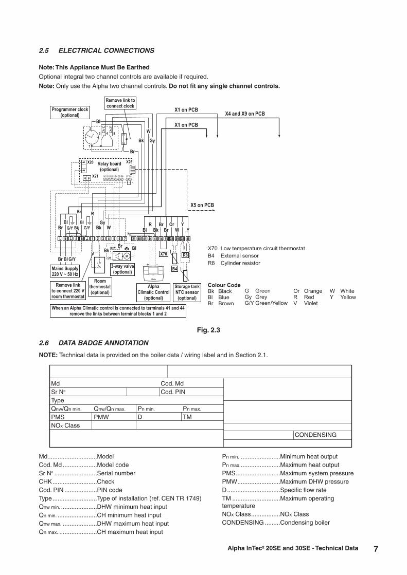
Note: This Appliance Must Be Earthed
Optional integral two channel controls are available if required.
Note: Only use the Alpha two channel controls. Do not fit any single channel controls.
2.5 ELECTRICAL CONNECTIONS
Fig. 2.3
2.6 DATA BADGE ANNOTATION
MdSr No
TypeQnw/Qn min.
PMSNOx Class
Qnw/Qn max.
PMW
Cod. MdCod. PIN
Pn min.
DPn max.
TM
CONDENSING
Md.............................ModelCod. Md ....................Model codeSr No .........................Serial numberCHK ..........................CheckCod. PIN ...................PIN codeType ..........................Type of installation (ref. CEN TR 1749)Qnw min. .....................DHW minimum heat inputQn min. .......................CH minimum heat inputQnw max. ....................DHW maximum heat inputQn max. ......................CH maximum heat input
Pn min. .......................Minimum heat outputPn max. .......................Maximum heat outputPMS ..........................Maximum system pressurePMW .........................Maximum DHW pressureD ...............................Specific flow rateTM ............................Maximum operating temperatureNOx Class .................NOx ClassCONDENSING .........Condensing boiler
NOTE: Technical data is provided on the boiler data / wiring label and in Section 2.1.
X5 on PCB
X1 on PCB
X1 on PCBX4 and X9 on PCB
Colour CodeBk Black
Bl Blue
Br Brown
G Green
Gy Grey
G/Y Green/Yellow
Or Orange
R Red
V Violet
W White
Y Yellow
X70 Low temperature circuit thermostat
B4 External sensor
R8 Cylinder resistor
Programmer clock(optional)
X21
X26
50 51 52 53 54 55 56 57 58
X20 Relay board(optional)
Remove link toconnect clock
Mains Supply220 V ~ 50 Hz
Remove linkto connect 220 Vroom thermostat
Roomthermostat(optional)
When an Alpha Climatic control is connected to terminals 41 and 44remove the links between terminal blocks 1 and 2
Bk
Bk
Bl
Br
Gy
W
W
R
Gy
Br
Bl
Bk
BlBr G/Y G/Y
Br
Br
Bl
Bl
G/Y
Bk
L N A B 1 2 3 4 6 75
Storage tankNTC sensor(optional)
3-way valve(optional)
AlphaClimatic Control
(optional)
X70
B4
R8
R Br Or YBl Bk Br W Y
21 40 41 44 41 14 15 38 39 38 48
CH
DHW
M
2
1
3 4 5Ch
1
Ch
2

8
2.7 BOILER SCHEMATIC
1 - Gas valve
2 - Expansion vessel
3 - Primary heat exchanger
4 - Air/gas mixer
5 - Fan
6 - Ignition/detection electrode
7 - Air test point (pressure point -)
Fig. 2.4
8 - Flue test point (pressure point +)
9 - Flue temperature sensor
10 - Manual air vent
11 - Primary temperature sensor
12 - Overheat thermostat
13 - Return thermostat
14 - Automatic air vent
15 - Pump
16 - Primary pressure switch
17 - Automatic bypass
18 - Drain point
19 - Condensate trap
20 - Safety valve
21 - Safety valve indicator
Alpha InTec² 20SE and 30SE - Technical Data
Gas
Condensate dischargeand expansion relief
PrimaryHeatingreturn
PrimaryHeating flow
9
10
11
12
14
15
16
17
18
19
20
21
8
7
6
5
4
3
2
1
F(+) A(-)
13

9
3.1 GAS SUPPLY
The meter and supply pipes must be capable of delivering the required quantity of gas in addition to the demand from any other appliances in the house.Refer to Technical performance data in Section 2.1 and 2.2.The complete installation, including the meter, must be tested for gas tightness and purged as described in BS 6891.
3.2 ELECTRICAL SUPPLY
The boiler requires a 230/240 V ~ 50 Hz mains supply, fused at 3 A
The boiler must be earthed.
There must only be one common isolator, providing complete electrical isolation, for the boiler and any external controls.
This boiler has been fitted with a supply cable, however, if it is necessary to fit a cable use PVC insulated cable not less than 0.75 mm² (24 x 0.2 mm) to BS 6500 Table 16. The boiler should be connected to a fused three pin plug and unswitched shuttered socket outlet (both complying with BS 1363), or a fused double pole switch with a contact separation of at least 3 mm in both poles.
Wiring external to the boiler must be in accordance with the current IEE Wiring Regulations (BS 7671).
Note: If a room thermostat is fitted, it must be suitable for 230/240 V switching.
3.3 AIR SUPPLY
The boiler does not require any air vents for cooling in the room in which it is installed or when installed in a cupboard or compartment. The minimum clearances for servicing must always be maintained.
Note: A cupboard or compartment used to enclose the boiler must be designed and constructed specifically for the purpose, i.e. comply with the Building Regulations.
3.4 FLUE SYSTEM - Fig. 3
The flue system must be installed in accordance with BS 5440:1.
When using the horizontal flue kit supplied ensure that the flue outer duct is installed horizontally (please note that the flue inner duct already has a pre-determined slope towards the boiler for condensate to run back towards the boiler).
When additional flue extensions are used, ensure the flue slopes downwards towards the boiler by a minimum of 25 - 30 mm per metre of flue.
Horizontal and vertical flue assemblies should be supported approximately every 1.5 m with access provided to the joints.
Flue components are available as follows:-
CD 750 mm flue extension - Part No. 6.2000750.
CD 1000 mm flue extension - Part No. 6.2001050.
CD 100 mm flue support brackets (pack of 5) - Part No. 6.1000355.
CD 90° bend - Part No. 6.2000590.
CD 45° bend - Part No. 6.2000545.
CD Vertical flue terminal kit - Part No. 6.2000520. Refer to the separate installation instructions supplied with the kit.
Note: 1. If an extra 90° bend is used, this reduces the maximum flue length by 1.3 m. Each 45° bend used reduces the maximum flue length by 0.9 m.
2. For flue lengths over 4.5 m the 'F0' parameter should be changed - See Section 5.4.
3. Under no circumstances must the flue length (including allowances for extra bends) exceed 12 metres horizontally and only 14 metres vertically.
4. Failure to use Alpha flue components with the boiler will invalidate the boilers CE approval, guarantee and may be unsafe.
3 GENERAL BOILER INFORMATION
Alpha InTec² 20SE and 30SE - General Boiler Information
10
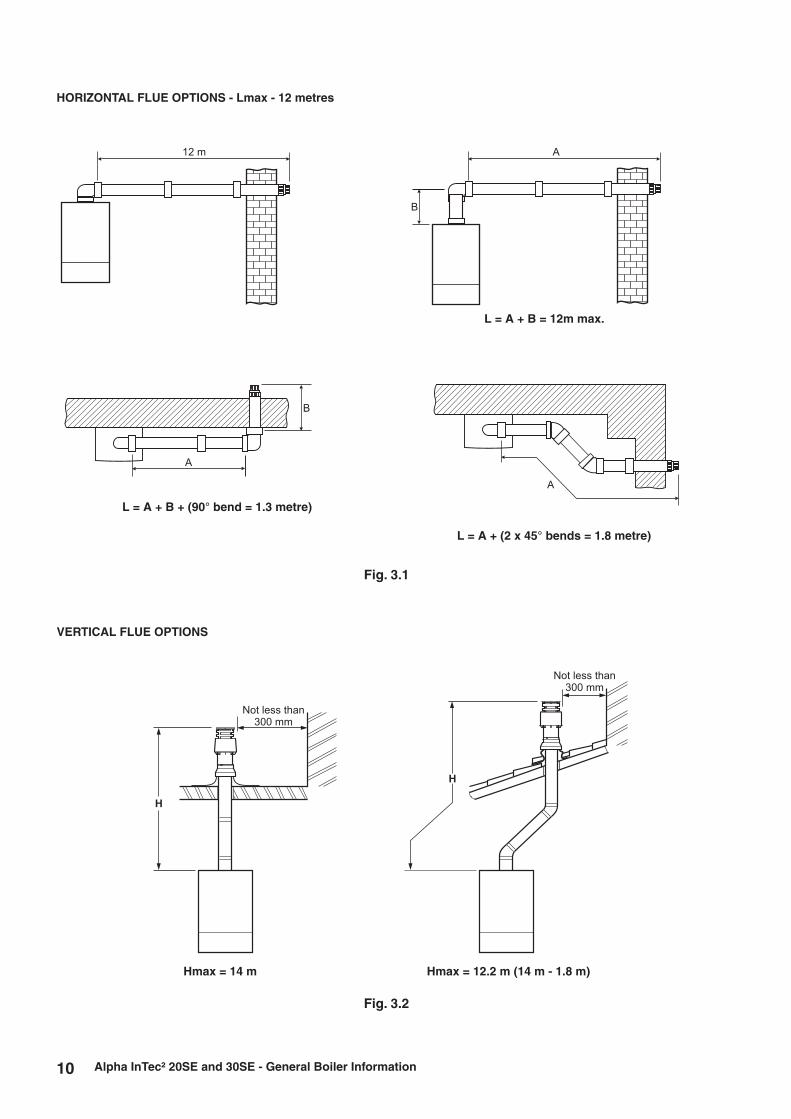
L = A + B = 12m max.
Alpha InTec² 20SE and 30SE - General Boiler Information
L = A + B + (90° bend = 1.3 metre)
L = A + (2 x 45° bends = 1.8 metre)
Fig. 3.2
VERTICAL FLUE OPTIONS
Hmax = 14 m Hmax = 12.2 m (14 m - 1.8 m)
12 m
B
A
A
B
A
HORIZONTAL FLUE OPTIONS - Lmax - 12 metres
Not less than
300 mm
H
Not less than
300 mm
H
Fig. 3.1

11
3.5 FLUE TERMINAL LOCATION - Figs. 3.3 and 3.4
Notes:
1. In addition, the terminal should not be nearer than 150 mm to the framework of an opening into the building, i.e. a window surround or door surround.
2. This clearance may be reduced to 25 mm without effecting the performance of the boiler. However, to ensure the condensate plume does not affect adjacent surfaces a clearance of 300 mm is preferable.
3. These clearances may be reduced to 25 mm without effecting the performance of the boiler. However, to ensure the condensate plume does not affect adjacent surfaces the terminal can be extended beyond gutters, pipes, eaves, balconies etc. by upto 500 mm. If the flue is extended more than 500 mm outside, it should be boxed and insulated.
4. To reduce the possibility of nuisance to neighbouring buildings etc. it is recommended the terminal should not be less than 2500 mm from car parking spaces, building boundary walls, fences etc.
5. A terminal must not be sited under a car port roof.
6. In certain weather conditions the terminal will emit a plume of steam. If possible avoid positioning the terminal where this may cause a nuisance, i.e. positions A, D, G, H, J or M.
7. The flue terminal must be exposed to the external air and the position must allow the free passage of air across it at all times.
8. A terminal must not be sited below 2 m where people have access to, such as public footpaths, access routes, patios etc. However, If the terminal is fitted less than 2 m above a surface where there is no public access, the terminal must be protected by a terminal guard. A suitable guard is available from Alpha Therm Ltd.
Alpha InTec² 20SE and 30SE - General Boiler Information
A Directly below an opening, air brick, windows, etc.
B Below gutters, soil pipes or drain pipes
C Below eaves
D Below balconies
E From a vertical drain pipe or soil pipe
F From an internal or external corner
G Above ground, roof or balcony level
H From a surface or boundary facing the terminal
I From a terminal facing the terminal
J Above an opening, air brick, window etc.
K Vertically from a terminal on the same wall
L Horizontally from a terminal on the same wall
M Horizontally from an opening, air brick, window etc.
N Minimum protrusion through a roof
O From a vertical obstruction
P From an openable window
Q From an adjacent vertical terminal
Min. distance (mm)Terminal position
300 (See Note 1)
75 (See Note 3)
200 (See Note 3)
200 (See Note 3)
150 (See Note 3)
300 (See Note 2)
300
600 (See Note 4)
1200 mm
300 (See Note 1)
1500 mm
300 mm
300 mm (See Note 1)
300 mm
300 mm
600 mm
600 mm
J
D
G
H I
Q
Boundary
O P
N
Fig. 3.3

12
Proximity of flue duct outlets to boundaries
The flue duct shall be sited so that it is at least 600 mm (see Fig. 3.4) from the boundary line when facing it and at least 300 mm from the boundary line when running parallel to it.
Fig. 3.4
600 mm
2000 mm600 mm300 mm
300 mm
Terminal facing the boundary
Terminal facing an opening
in adjacent building
Terminal at an angle to the boundary
Terminal parallel to the boundary
Boundary
Boundary
Boundary
Boundary
Terminal
Terminal
Terminal
Terminal
Building Building
Building
Building
Adjacent buildingWindow
3.6 BOILER LOCATION
The boiler is not suitable for external installation unless it is installed within a purpose designed weatherproof building.The boiler must be installed on a flat vertical wall which is capable of supporting the weight of the boiler. The boiler can be fitted to or adjacent to a wall comprising of a combustible material without the need for a special thermal insulation barrier.If the boiler is to be fitted in a timber framed building, it should be fitted in accordance with the Institute of Gas Engineers 'Guide for Gas Installations in Timber Frame Housing', reference IGE/UP/7.
The boiler may be installed in any room or internal space, although particular attention is drawn to the requirements of the current IEE Wiring (BS 7671) Regulations, and in Scotland, the electrical provisions of the Building Regulations applicable in Scotland, with respect to the installation of the boiler in a room or internal space containing a bath or shower. Where a room-sealed boiler is installed in a room containing a bath or shower, it must not be possible for a person using the bath or shower to touch any electrical switch or boiler control utilising mains electricity.
The boiler may be installed in a cupboard or compartment, provided it is correctly designed for that purpose, i.e. complies with the Building Regulations and the requirements of BS 6798.
Alpha InTec² 20SE and 30SE - General Boiler Information

13
3.7 CENTRAL HEATING SYSTEM - Fig. 3.5
The boiler is designed for use in a sealed central heating system in accordance with the requirements of BS EN 12828 and BS 6798.
The system should be designed to operate with flow temperatures of up to 90°C. When designing the system, the pump head, expansion vessel size, mean radiator temperature, etc. must all be taken into account. Refer to the pump performance table for guidelines.
System volume - The expansion vessel incorporated into the boiler is suitable for a sealed heating system with a maximum water content of 80 litres (18 gal). Above 80 litres, consideration should be given to fitting an additional expansion vessel fitted in the position shown in Fig. 32.5. To check correct operation of the expansion vessel(s) the system pressure should not be more than 2.5 bar when the system is at maximum operating temperature (for further guidance refer to BS 7074:1).
The boiler is supplied with the following components built in:-
Pressure gauge - To indicate the system pressure to be maintained.
Expansion vessel - Conforming to BS 4814 with a capacity of 8 litres and pre-charged to a pressure of 1.0 bar.
By-pass - The boiler incorporates an automatic by-pass, therefore an automatic by-pass is not required for the system.
3.8 FILLING THE CENTRAL HEATING SYSTEM - Fig. 3.6
The system design pressure (cold) should be set to 1.0 bar. This pressure is equivalent to a static head (see Fig. 3.5) of 10.2 metres of water.
Provision must be made for filling the system. This is done by the use of a filling loop. See Fig. 3.6. A filling loop is not supplied with this boiler.
Filling of the system must be carried out in a manner approved by the local Water Undertaking. Where allowed, the system may be filled via a temporary connection as shown in Fig. 3.6. After filling, always disconnect the flexible hose of the filling loop.
All fittings used in the system must be able to withstand pressures up to 3 bar.
Drain taps (to BS 2879) must be used to allow the system to be completely drained.
Fig. 3.5
Fig. 3.6
Filling looptemporarily connected
Heating circuit return
Mains water supplyStop
valve
Hose unions
Stop valve
Double check valve assembly
Test cock
Alpha InTec² 20SE and 30SE - General Boiler Information
Automatic
air vent
Additional expansion
vessel (if required)
Filling point
Static head of system
Heating return
System
drain tap
Heating flow
Note: A drain tap should be installed at the lowest
point of the heating circuit and beneath the appliance.
Boiler

14
3.9 FLUSHING THE HEATING SYSTEM
It is essential that the central heating system is thoroughly cleaned and flushed when fitting an Alpha boiler. Failure to do so will invalidate the warranty.
The primary condensing heat exchanger is constructed in aluminium and therefore is compatible with most materials used in a heating system.
Cleaning agents and inhibitors must be applied in accordance with their manufacturers instructions. Suitably approved products for cleaning and treatment must be used.
The system should be flushed in accordance with BS 7593 and BS EN 14336. The following procedures are recommended:
1. Installing onto a new system:- a. Fill the system, vent at high points, at pump, primary heat exchanger and radiators. b. Check for leaks. c. Drain the system. d. Chemically clean the system as instructed by the recommended cleaner manufacturer. Note: Ensure that the system is flushed to remove any remains of the cleaner. e. If chemical cleaner is not used to clean the system:- i) Refill the system. ii) Switch on the boiler and allow the system to heat up to the normal operating temperature. iii) Switch off the boiler and drain the system while the water is still hot. iv) Refill the system and check for leaks. f. Add the inhibitor to the system as instructed by the inhibitor manufacturer instructions.
2. Installing onto an existing system, clean the system before fitting the new boiler:- a. If the old boiler is still working:- i) Switch on the boiler and allow the system to heat up to the normal operating temperature. ii) Switch off the boiler and drain the system while the water is still hot. iii) Refill and chemically clean the system as instructed by the cleaner manufacturer instructions. iv) Ensure the system is flushed to remove any remains of the cleaner. v) Fit the new boiler. b. If the old boiler is not working:- i) Drain the system. ii) Remove the old boiler. iii) Flush the system through. iv) Fit the new boiler. v) Refill and chemically clean the system as instructed by the cleaner manufacturer instructions. vi) Ensure the system is flushed to remove any remains of the cleaner and check for leaks. c. Add the inhibitor to the system as instructed by the inhibitor manufacturer instructions.
The system inhibitor level must be maintained at the correct concentration. The PH of the system water must be between 6.5 and 8.5 or the appliance guarantee will be invalidated.
The system must not be filled with softened water.
3.10 DISPOSAL OF CONDENSATE
Provision must be made for the safe disposal of condensate produced by the flue gases of the Alpha boilers and reference should be made to BS 6798 for the requirements on the disposal of condensate.
The boilers incorporate a condensate trap which has a seal of greater than 75 mm, therefore no additional trap is required.
The condensate should ideally be discharged internally into an internal waste pipe (washing machine/sink waste) or soil pipe to avoid the possible risk of freezing. The pipework must be in 22 mm pipe (minimum).
External pipe runs should be avoided, but if it is necessary, the pipework should be protected from the risk of freezing with waterproof insulation and the length should be kept to a maximum of 3 m and the condensate pipework should be increased to a minimum of 32 mm diameter. Termination should be into an external gulley or soakaway as shown in Figs. 3.7 and 3.8.
Note: All pipework must have a continuous fall (see Figs. 3.7 and 3.8) from the boiler and must be of an acid resistant material such as plastic waste pipe. (copper or steel is not suitable).
The condensate pipe is combined with the expansion relief discharge. The flexible condensate hose supplied meets the requirements for use with both condensate and expansion relief. This should be connected to a suitable waste pipe and fittings with approval for hot and cold water, i.e. BS EN1451-1PP Waste piping, BS EN1455-1 ABS piping or BS EN 1566-1 MUPVC piping.
The condensate and discharge should be connected to a drain for sewage and foul waste or a dedicated soak away with neutraliser added.
It should be noted that the connection of a condensate pipe to a drain may be subject to local building control requirements.
Alpha InTec² 20SE and 30SE - General Boiler Information

15
Fig. 3.8 - External soakaway
Alpha InTec² 20SE and 30SE - General Boiler Information
Ground level (either/or)
22mm termination from boiler, increase to 32 mm if external
2½ fallO
25mm
300mm
Two rows of 3 x 12mm
holes at 25mm centres,
50mm from the bottom
of the tube. Holes to face
away from house.
Cement mortar sealing
100mm plastic tube
Bottom of tube sealed
Soakaway depth 400mm
filled with limestone chippings
500 mm min.
Optional Condensate Trace Heating Kit
An optional Alpha trace heating kit is also available to prevent the condensate from freezing.The control of this kit works with a unique patented design using the boiler PCB to control the trace heating. The outside weather probe measures the external temperature, activating the trace heating cable only when the boiler is in operation and producing condensate. This feature together with the latest technology variable resistance heating cable ensures only a small amount of electrical energy is used.If the external temperature drops below 2°C and the boiler is on, the relay PCB is operated and voltage is supplied to the trace heating wire causing it to heat up and prevent the condensate from freezing. When the outside temperature rises to 4°C or the boiler pump stops, the trace heater is switched off. The connection of the outside weather probe supplied with this kit also enables the weather compensation feature on the boiler.
Fig. 3.7 - External gully
Open end of pipe
diverted into gully
below grid but above
water level
Use waterproof
pipework insulation
in very exposed
positions
Ensure pipe is
adequately supported
Plastic pipe
(minimum 32 mm)
Minimum gradient 2½°

16
4.3 PREPARE THE WALL - Fig. 4.2
1. Decide upon the position of the boiler taking into account the clearances required for servicing and the flue terminal position.
2. Tape the template to the wall (ensure it is level and the right way up) and mark the position of the holes for the boiler mounting bracket. If rear exit flue is used, mark the position of the hole for the flue.
3. Side exit flue - Continue the horizontal centre line of the flue across the wall to the side wall, then along the side wall 135 mm (ensure the lines are horizontal). This will give the position of the centre of the hole for the flue.
4. Cut the 110 mm diameter hole (or use a 107 mm core drill) in the wall for the flue.
Notes: 1. Ensure the hole is horizontal. 2. For internal fitting of the flue, using the flue sealing
collar supplied, cut a 130 mm dia. flue hole using a 127 mm core drill.
5. Drill the fixing holes (10 mm dia.) to accept the No.10 plugs supplied. Using the screws supplied, fit the mounting bracket.
4 INSTALLATION
Fig. 4.1
Alpha InTec² 20SE and 30SE - Installation
4.1 UNPACKING
1. The boiler carton also contains the following:-
Connection kit (union bends, washers and valves)
Mounting bracket plus screws and wall plugs
Condensate discharge pipe
Literature pack and Wall template
A suitable Alpha flue system must be selected to use with the boiler.
Notes: a. All flues must be suitable for Alpha condensing boilers. b. CD 750 mm and 1000 mm flue extensions are available, if required.
2. Unpack boiler and remove the loose items, packs and mounting bracket.
Note: The boiler can be stood in an upright position (only while the valves and union bends are not fitted).
It is recommended that two persons lift the boiler.
4.2 CLEARANCES REQUIRED - Fig. 4.1
Fig. 4.2
= =
Template
Outline of
boiler
135 mmEnsure line is levelRear exit hole
110 mm dia.
Position of
110 mm hole
to be cut for
side exit flue
143 mm
Fixing holes
if wall jig used
Fixing holes
if mounting
bracket used
Minimum clearances
712 mm
Minimum
clearance
of 450 mm
from front
of boiler
276 mm
440 mm5 mm 5 mm
150 mm
235 mm - Can be reduced to
150 mm when using a
vertical flue

17Alpha InTec² 20SE and 30SE - Installation
4.4 FIT THE BOILER - Refer to Figs. 4.2 and 4.3
Lift the boiler and locate it on the mounting bracket - the boiler should be lifted by two persons.
Note: When handling or lifting always use safe techniques - keep your back straight, bend your knees, don't twist - move your feet, avoid bending forwards and sideways and keep the load as close to your body as possible.Where possible transport the boiler using a sack truck or other suitable trolley.Always grip the boiler firmly, and before lifting feel where the weight is concentrated to establish the centre of gravity, repositioning yourself as necessary.
4.5 CONNECT THE PIPEWORK - Fig. 4.4
1. Thoroughly flush out all the water pipework. Refer to Section 3.9.
2. Fit the valves to the boiler connections as shown in Fig. 4.4 - note the colours of the operating levers.
3. Connect the system pipework to the union fittings on the valves just fitted.
Note: When soldering bends, ensure they are not connected to the valves, otherwise the internal seals may be damaged.
One metre of copper pipe must be fitted to the boiler before connecting to any plastic pipework.
4. Connect the flexible condensate pipe to the rubber connector as shown in Fig. 4.4. Using the adaptor supplied, connect the flexible pipe to the condensate drain.
Ensure that the condensate discharge pipe is as required in Section 3.10.
5. Ensure that all the valves are closed (operating lever at right angle to valve) and do not turn on the water or gas supplies at this stage.
Fig. 4.3 - rear of boiler
Location forwall mountingbracket onrear of boiler
Pour water into flue duct
Fig. 4.4
A - Gas inlet - Yellow (22 mm)
C - Heating return - (22 mm)
D - Heating flow - (22 mm)
Safety valve operation indicator
Condensate discharge pipe
Heating drain point
Gas service cock (yellow)
Heating return valve
Heating flow valve
Electrical connection
A B C
65 4570
Bottom cover plate

18
4.6 FIT THE FLUE - Figs. 4.5 and 4.6
The following procedure applies to fitting an Alpha CD Easy-Flue to both rear or side exit flue - horizontally only.
1. The CD Easy-Flues are suitable for use in the flue length ranges shown in the tables below.
Note: Where the length is less than the minimum or more than the maximum, refer to Section 4.7.
Alpha InTec² 20SE and 30SE - Installation
3. Adjust the telescopic section of the flue to the distance ‘L’, ensuring that the two labels marked ‘TOP’ are aligned, then seal and secure the joint between the ducts with the sealing tape supplied.
Note: Always ensure that there is a minimum overlap of 25 mm when fully extending the telescopic section.
4. Pass the flue assembly through the wall (from inside or outside). Note: Internal fitting - If there is no access to make good the outside wall, locate the outside (black) flue sealing collar
onto the outer duct of the flue immediately before the terminal grille onto the location provided. Push the flue assembly through the 130 mm flue hole, so that the collar completely passes through the wall. Then pull the flue assembly back into the correct position. Visually check that the collar is sealing the outside wall and that it is not restricting any of the openings of the flue terminal.
Fig. 4.7
Fig. 4.5 Fig. 4.6
CD Easy-Flue
500 mm
1000 mm
B (mm)
Max
530
975
Min
305
765
CD Easy-Flue
500 mm
1000 mm
Max
440
885
Min
215
675
B + C (mm)
Note: Add 45 mm to dimension B if the wall jig is used.
(B)
Rear
Flu
e
(B + C)
Side Flue
Seal Joint with Tape
L
2. Determine the overall length (L) of flue required, (see Fig. 4.7) as follows:-
Rear flue L = wall thickness (B) + 60 mm (105 mm if the wall jig is used)
Side flue L = wall thickness (B) + distance between boiler and wall (C) + 145 mm

19Alpha InTec² 20SE and 30SE - Installation
5. Position the smaller Easy-Flue 40 mm clamp (with seal) supplied, over the bend. Fit the bend to the boiler and rotate to the correct position. Secure in position using the clamp. Ensure the clamp is located centrally over both the bend and boiler adaptor.
6. Fit the inside (white) flue sealing collar over the Easy-Flue. If it was not previously fitted, fit the outside (black) flue sealing collar onto the flue immediately before the terminal grille onto the location provided.
7. Slide the larger Easy-Flue 45 mm clamp over the outer duct and pull the flue assembly towards the bend, locating the inner duct into the seal joint on the bend. Ensure the labels marked 'TOP' are positioned at the top before securing the flue assembly to the bend with the clamp (three screws) located centrally over the joint.
Note: Check the flue terminal protrudes 120 mm out of the wall and the inner duct of the terminal is positioned correctly (see Fig. 4.9).
8. Make good the inside wall by pushing the inside flue sealing collar upto the wall.
The hole around the flue can be made good using the flue sealing collars supplied or using a suitable sealant/cement if required.
Fig. 4.8 - Fitting the flue from inside
Check collar is sealingthe wall and it is notrestricting any openingsof the flue terminal
130 mm
Fig. 4.9 - Rear flue
Allow 20 mm 30 mm
Do not cut past this point
Fig. 4.10
4.7 REDUCING THE FLUE - Fig. 19
When the flue length required is less than the minimum stated in Section 4.6, paragraph 1, refer to Fig. 4.10.
Discard the first telescopic section (not the section with the terminal) of the Easy-Flue 1000 mm or 500 mm and cut to the required length.
Note: Ensure that all cuts are square and free from burrs.Once assembled with the components pushed home, the flue is fully sealed.
120
Inner duct
Elbow seal joint
90° bend
Easy-Flue
40 mm clamp
and seal
Easy-Flue 45 mm clamp
Terminal
Flue sealing collar
Note: Ensure the outer flue duct is horizontal
Side of boiler
CD Easy-Flue
Ensure the inner duct within
the terminal is at the top.
The inner duct must
be positioned to slope towards
the boiler
Note:
20
65
Inner duct seal
40 (85 if wall jig used)
135 (180 if wall jig used)

20 Alpha InTec² 20SE and 30SE - Installation
Rear Flue length (B)
Up to maximum:-11.890 m
(Subtract 45 mm if the wall jig is used)
Side Flue length (B + C)
Up to maximum:-11.805 m
Comments
Alpha CD 750 mm flue extension (Part No. 6.2000750) or 1000 mm extension (Part No. 6.2001050) is required to extend the range of telescopic flue.Refer to Section 4.8 for instructions on how to extend the flue.Note: A 130 mm flue hole (127 mm core drill) may be required in the wall. This is when the extended flue is passed through the wall.
Additional support brackets are required when extending the flue. These are available from Alpha, Part No. 6.1000355.
Easy-Flue 45 mm clamp
Easy-Flue
40 mm clamp
and seal
45
Front of boiler
Extension clamp
Inner seal joint
Inner seal joint
Flue length (L)
90° bend
Seal joint
CD Easy-Flue
Ensure outer flue duct of Easy-Flue is horizontal
Ensure the flue extension slopes
downwards towards the boiler by a
minimum of 25 - 30 mm per metre
CD Flue extension
Flue sealing
collar
Ensure the inner duct within the terminal is at the top.
The inner duct must be positioned to slope towards the boilerNote:
120
Terminal
20
125
220
Fig. 4.11 - Side flue
4.8 EXTENDING THE FLUE - Fig. 4.11
Note: The flue assembly length must not exceed the maximum length stated, including the equivalent lengths of any extensions, bends etc. used for plume management components. InTec² boilers must not exceed the maximum of an equivalent horizontal flue length of 12 m.
1. When the flue length required is more than the maximum stated in Section 4.6, paragraph 1, refer to the table below and Figs 4.5 and 4.6.
2. Use the template (supplied with the boiler) to mark the required flue position, ensure the slope towards the boiler is correct.
3. Determine the overall flue length as described in Section 4.6, paragraph 2 to determine the number of Alpha CD 750 or 1000 mm flue extensions required.
4. Assemble the flue extensions together by locating the inner duct into the seal joint and secure each extension together with the extension clamps supplied (three screws). Ensure that the clamps are positioned centrally over the joints.
Note: If it is required to cut an extension, DO NOT cut the end of the inner duct that incorporates the seal joint. Ensure the inner duct end without the seal joint is cut so that it is 20 mm longer than the outer duct.
Ensure that all cuts are square and free from burrs. Once assembled with the components pushed home, the flue is fully sealed.
5. Adjust the telescopic section of the Easy-Flue to the required length and secure the Easy-Flue with the sealing tape supplied. Fit the Easy-Flue to the extensions by locating the inner duct into the seal joint and secure with the clamp (three screws), ensuring it is located centrally over the joint.
6. Mark the end of the flue assembly 'TOP' where it is connected to the boiler, so that the 'TOP' of the flue terminal is aligned with the 'TOP' at the boiler end of the flue assembly.
7. Pass the complete flue assembly through the wall.
8. Position the smaller Easy-Flue 40 mm clamp (with seal) supplied, over the bend. Fit the bend to the boiler and rotate to the correct position and secure in position. Ensure the seal is located centrally over both the bend and boiler adaptor. If the inside sealing collar (white) is being used to make good the inside wall, then it will need to be fitted before assembling the flue.
9. Slide the larger Easy-Flue 45 mm clamp (two screws) over the outer duct and pull the flue assembly towards the bend, locating the inner duct into the seal joint on the bend.

21Alpha InTec² 20SE and 30SE - Installation
Fig. 4.12
1
1
2
10. Secure the flue assembly to the bend with the clamp ensuring it is positioned centrally over the joint, ensuring the ‘TOP’ marked on the outer duct is positioned at the top.
Note: Check the flue terminal protrudes 120 mm out of the wall and that the inner duct of the terminal is positioned correctly, i.e. the inner duct within the terminal is at the top. See Fig. 4.11.
11. Make good the outside wall by fitting the outside sealing collar (black) onto the location provided immediately behind the flue terminal grille. Make good the inside wall using the inside sealing collar (white) if required.
4.9. FIT PLUME MANAGEMENT COMPONENTS - (OPTIONAL)
The following procedures detail the options for management of the exhaust flue gas/plume emitted from the terminal.
a. The terminal supplied with the Easy-Flue can be altered to divert exhaust flue gas/plume at an angle.
This can be achieved by simply turning the end section of the terminal to the desired angle.
b. The CD Easy-Flue can be converted to allow the inner flue duct to be extended so as to position the terminal in an area where the exhaust flue gas/plume will not cause a nuisance. This can be done before or after installation of the flue, providing there is access to the terminal from outside.
i. Remove the screws (1 in Fig. 4.12) securing the terminal and remove the terminal by pulling it from the flue assembly. Remove the screw (2 in Fig. 4.12) securing the terminal end section and remove the end section from the terminal.
ii. Locate a 93° Plume Management bend into the flue assembly and rotate it to the direction required. iii. Connect to the 93° bend the required Plume Management components as detailed and refer to Fig. 4.13. Notes: 1. The wall support brackets must be used to secure the Plume Management pipework to the wall and
prevent disconnection of the 93° bend from the flue assembly or any other component. 2. Each joint must be secured with one of the screws provided to prevent accidental disconnection. 3. Ensure there is always a slight slope towards the flue assembly fitted in the wall and there is no part
of the plume management pipework where condensate/rain will collect and cause a blockage or any restriction.
iv. Terminate the Plume Management pipework by fitting the terminal end section (push-fit) previously removed. Refer to Fig. 4.13.
v. The Plume Management components available for extending the inner flue duct are as follows:-
Plume Management 93° bend 60 mm dia. (each 93° bend equivalent to 1.3 m flue length) Plume Management 45° bend 60 mm dia. (each 45° bend equivalent to 0.9 m flue length) Plume Management 1000 mm extension 60 mm dia. (equivalent to 1 m flue length) 60 mm dia. wall bracket

22 Alpha InTec² 20SE and 30SE - Installation
PM length = C + (1 x 93° bend = 1.3 m) + (2 x 45° bends = 1.8 m)
C
Min.
400 mm
CD Easy-Flue
Flue sealing collar
Terminal end section
from CD Easy-Flue
PM length = C + (2 x 93° bend = 2.6 m) + (2 x 45° bends = 1.8 m)
C
Terminal end section
from CD Easy-Flue
PM length = C + (4 x 93° bend = 5.2 m)
C
Terminal end section
from CD Easy-Flue
Ensure there is a slope of approximately
3° back towards the Easy-Flue
Fig. 4.13
Note: The equivalent horizontal flue assembly length + the equivalent plume management length (PM length) must not exceed the maximum flue length stated for each boiler, i.e.
Alpha InTec² boiler maximum equivalent flue length must not exceed 12 metres.
Note:
1. Ensure each joint is secured with the screw supplied.
2. Ensure there is always a slight slope towards the CD Easy-Flue so that there is no part of the pipework where condensate will collect.

23Alpha InTec² 20SE and 30SE - Installation
4.10 CONNECT THE MAINS SUPPLY - Figs. 4.14 and 4.15Gain access to the boiler terminal block 'D' as follows:-
Remove the case front panel, refer to Section 6.2.
Remove the control panel cover 'B'.
1. Remove the two screws 'A' in Fig. 4.14.
2. Depress the two clips on the control panel cover.
3. Remove the cover 'B' from the control panel 'C'.
Refer to Technical Data, Section 2.5 for connection details.
Note: This boiler has been fitted with a mains supply cable. However, if it is necessary to fit an alternative supply cable, ensure the cable clamp that has been fitted is removed and connect as follows:-
Pass the mains supply cable through the cable clamp and connect as follows:- Brown to L, Blue to N and Green/Yellow to . Ensure correct polarity.
Note: Ensure that the length of the earth wire is such that if the supply cable is pulled out of its clamp the live and neutral wires become taut before the earth wire.
Do not switch on the electrical supply at this stage.
If an external control, i.e. room thermostat or external clock is to be fitted, remove the link between terminals 1 and 2. Pass the cable through the cable clamp and connect it to terminals 1 and 2. (Refer to Section 2.5).
Leave the control panel open until commissioning procedures have been completed.
Carry out electrical system checks - Short circuit, Polarity, Earth continuity and Resistance to earth with a suitable multimeter.
4.11 FITTING BOILER CONTROLS
It is recommended that Alpha controls are used with the boiler to maintain efficient and correct operation of the boiler. Please note that using controls that are not supplied or recommended by Alpha may invalidate the boiler warranty and may not control the boiler correctly.
Alpha offer a number of controls options from simple in-built mechanical timers to remote wireless programmable controllers.
The Alpha Climatic Programmable Modulating Boiler Energy Manager is a two-channel time and temperature programmer with integrated thermostat and 'BUS' system to transfer data between the boiler and controller, enabling full remote control of the boiler functions and display of information. With enhanced boiler control, the unit further increases boiler and system efficiency. Alternatively standard programmable room thermostats or mechanical and digital boiler clocks are available.
Note: Only use a Climatic or suitable single channel Alpha controller. Do not fit a two channel controller.
Connecting Controls
Remove the control panel cover as described in Section 4.10, if it has not already been removed.
Note: Do not remove the 230 V controls connection cover, see Fig. 4.15
Climatic RF receiver installation
1. Plug the connecting wire onto the Climatic receiver PCB supplied with the controller.
2. Using the two screws provided, fix the receiver PCB into position.
3. Route the wire along the groove in the control panel to terminal block connections 44 and 41 (the wires can be connected either way round).
4. Replace the control panel cover in reverse order.
Fig. 4.14
A A
B
C
D
2
2
1
1
3
Fig. 4.15
Cable clampsCable entry
Connections cover
Fig. 4.16
Climatic receiver

24 Alpha InTec² 20SE and 30SE - Installation
Comfort or Easy-Stat RF receiver and Digital or Mechanical Clock installation
1. Remove the screw securing the connections cover labelled 'connections for 230V controls' to expose the receiver/clock connections. See Fig. 4.15.
2. Remove the link between the red wires 3 and 4 and plug all wires on to their corresponding numbers on the receiver or clock.
3. Locate the receiver or clock onto the two pins and using the two screws provided fix into position.
4. Remove the round blanking panel from the cover panel and re-fit the control panel cover in reverse order.
Fig. 4.18
9 8 7 6 5
4
3
2
1
27 20 15 10 5 0 -5 -10 -15 -20
External temperature (°C)
Max.
Min.
System
temperature
(°C)
Comfort / Easy-Stat receiver
Connections cover
Blanking panel
Fig. 4.17
External Sensor – Weather compensation feature
The Alpha InTec² boilers have a built in weather compensation feature which is automatically activated when the external sensor is fitted – Part No 3.022383. When fitted the weather compensation sensor allows the boiler to control the maximum primary flow temperature to the heating circuit according to the outside temperature, heating the property more effectively and efficiently.
Operation
During a central heating on period the sensor monitors the external temperature and modulates the boiler heating output to give the correct flow temperature to maintain the required room temperature. If the external temperature drops then the flow temperature will increase, if the external temperature increases then the flow temperature will decrease. This reduces the amount of wasted energy and reduces gas consumption.
When an external weather sensor is fitted the CH temperature control dial will no longer adjust the flow temperature in °C, instead the display will show a scale of 1 to 9. Each number corresponds to a line on the graph in Fig. 4.18 e.g. line 6 will give a flow temperature of 60°C when the external temperature is 10°C.
Notes: 1. The temperature of the radiators will vary depending on the outside temperature; the required room temperature will still be maintained by the room thermostat.
2. The weather compensation sensor can only be used on an InTec² SE boiler when the Alpha diverter valve kit is used, otherwise the DHW temperature will be affected.

25
When commissioning the boiler, ensure the Benchmark Checklist at the back of these instructions is completed.
5.1 FILL THE SYSTEM
1. The boiler is fitted with an automatic air vent positioned on the pump (see Fig. 6.7), ensure that the vent is always open.
2. Open the central heating flow and return valves (operating lever in-line with valve) (see Fig. 4.4).
3. Open the fill point valves on the filling loop until water is heard to flow.
4. To remove the air - Vent each radiator in turn, starting with the lowest in the system.
5. Vent air from the primary heat exchanger via the manual vent at the top right hand side (see Fig. 6.7).
6. It is important that the pump is properly vented to avoid it running dry and damaging its bearings. Unscrew and remove the cap from the centre of the pump. Using a suitable screwdriver rotate the exposed spindle about half a turn, then replace the cap.
7. Check the operation of the safety valve (see Fig. 6.7) by turning the head anti-clockwise until it clicks. The click is the valve lifting off its seat allowing water to escape from the system - check that this is actually happening.
8. Continue to fill the system until the pressure gauge indicates 1.0 bar. Close the fill point valve and check the system for water soundness. Disconnect the filling loop from the mains supply.
Water may be released from the system by manually opening the drain point (see Fig. 6.7) until the system design pressure is obtained. The system design pressure (cold) should be between 0.75 and 1.25 bar.
Refer to Sections 3.8 and 3.9. Filling and Flushing the system.
9. Open the cold water mains inlet valve (see Fig. 4.4). Turn on all hot water taps and allow water to flow until no air is present. Turn off taps.
10. Ensure that the condensate trap has been filled with water.
The condensate trap will be filled automatically when venting the heat exchanger in paragraph 5 above.
5.2 BOILER CONTROLS - Fig. 5.1
Alpha InTec² 20SE and 30SE - Commissioning
5 COMMISSIONING
Fig. 5.1
1 On-Off/Standby button2 Summer/Winter button3 Reset button4 Information button5 Domestic hot water temperature
selector switch (with Alpha diverter kit only)
6 Central heating water temperature selector switch
7 Heating system pressure gauge8 DHW mode active (with Alpha diverter
kit only)
9 Boiler locked, requires reset via 'RESET' button
10 Flame present symbol and relative power scale
11 Operating in summer mode (with Alpha diverter kit only)
12 Operating in winter mode13 Central heating mode active14 Temperature indicator, boiler info and
error codes15 Boiler in Stand-by mode
16 Presence of external connected devices17 Solar function active (N/A on this model)18 Functioning with external temperature
probe active (optional)19 Boiler connected to remote control
(optional)20 Not used on this model21 Optional boiler controls (if fitted)
RESET
BOOST
bar
°C
x100rpm
8 9 10 11 12 13
14
151617181920
12345 621 7

26 Alpha InTec² 20SE and 30SE - Commissioning
5.3 TEST FOR GAS TIGHTNESS AND PURGE THE SUPPLY
1. With the boiler connected, pressure test the gas supply and inlet pipework connected to the boiler for tightness in accordance with BS 6891.
2. Loosen the gas inlet pressure test point screw on the gas valve (see Fig. 5.2) and purge in accordance with BS 6891.
3. Retighten the test point screw and test for gas tightness. Close the boiler gas service cock.
5.4 CHECK THE AIR FLOW THROUGH THE HEAT EXCHANGER
The following air flow check must be carried out and the reading logged in the box provided in the table below. This figure is then used as a reference during future servicing of the boiler to determine if the heat exchanger needs to be cleaned.
This check must be carried out with the front case fitted.
Before carrying out this check the flue must be fully installed and the condensate trap filled with water.
1. Remove the pressure test point caps at the top of the boiler and connect a digital differential pressure gauge across the positive (F+) and negative (A-) pressure connections, see Fig. 5.3.
2. Set the boiler to stand by and press and hold the reset and stand by buttons simultaneously for 15 seconds. The summer/winter symbol ( ) and the number 55 will flash on the display indicating that the fan is running at a fixed speed of 5500 rpm.
Note: The boiler does not fire during this operation.
3. Observe the pressure differential reading and compare it to the tables below and record the figure in the box at the bottom of the table to be used as a reference for future servicing.
If on a future service the pressure reading has reduced by 40% or more then the heat exchanger must be cleaned. Refer to Section 6.5.
i.e. If the measured value is less than 0.6 x the original reference value, the heat exchanger should be inspected and cleaned.
4. If during first commissioning the readings are not within those stated in the tables above then the flue must be checked for integrity and length. If the flue length exceeds 5 m then the 'F0' parameter should be changed to suit, see parameter settings in Section 5.14.
Note: If the 'F0' parameter has been changed then a fast calibration is required see Section 5.13. This is indicated by the code E72 shown on the display.
The air flow check function will operate for 15 minutes, alternatively disconnect the boiler electrical supply or press the standby button for 8 seconds to exit the function early.
InTec² 20SE
InTec² 30SE
'F0' parameter setting
0
1
2
Recorded pressure
reading
Pressure (mbar)
0 to 1.68
1.68 to 2.02
2.02 to 2.40
Indicative flue length (m)
From 0 to 4.5
From 4.5 to 9.0
From 9.0 to 13.0
'F0' parameter setting
0
1
2
Recorded pressure
reading
Pressure (mbar)
0 to 1.58
1.58 to 1.81
1.81 to 2.02
Indicative flue length (m)
From 0 to 4.5
From 4.5 to 9.0
From 9.0 to 13.0

27
5.5 INITIAL LIGHTING - Refer to Fig. 5.1
1. Before turning on the gas and electrical supplies check the heating system is filled to the correct pressure. Refer to Section 5.1 Fill the System. The pressure gauge on the right of the control panel indicates the heating system pressure. When the boiler is cold the needle should be within the green band.
2. With the gas and electrical supplies to the boiler off, ensure that the mains water inlet valve and the central heating flow and return valves are open.
3. Turn on the gas and electrical supplies to the boiler.
When the electricity supply is turned on, the boiler will automatically go through a system purging cycle for 8 minutes counting down from 96 on the display. This can be interrupted by pressing the RESET button (item 3 in Fig. 5.1). It is recommended that this cycle is allowed to complete when first lighting the boiler to help remove air from the system. After this the boiler will be in either Standby or On mode, the On-Off/Standby button (item 1 in Fig. 5.1) is used to scroll between these modes or press and hold it in to turn the boiler off.
Note: This does not isolate the electricity supply to the boiler.
4. Ensure all external controls are calling for heat.
If the optional controls are fitted, refer to the instructions supplied, and ensure they are in an 'on' mode.
5. Press the Summer/Winter button (item 2 in Fig. 5.1) to select either summer ( ) or winter ( ) mode.
Note: The Summer mode will only function if the Alpha diverter kit has been fitted. When using a standard 'Y' or 'S' plan system the boiler MUST BE left in Winter mode.
Summer ( ): In this mode the boiler will only fire when hot water is requested through opening a hot water outlet tap and the heating will not function even if requested by any controls. The desired hot water temperature can be set using the hot water selector switch (item 5 in Fig. 5.1) on the control panel, when the tap is open the display will indicate the actual primary flow temperature (item 14 in Fig. 5.1).
Winter ( ): In this mode the boiler will function in heating and hot water depending on the request from any controls fitted. The boiler will always prioritise hot water when any hot outlet tap is opened. The heating will activate depending on the request from any external controls fitted. The domestic hot water (item 5 in Fig. 5.1) and central heating (item 6 in Fig. 5.1) selector switches on the control panel can then be turned to the required set temperatures shown on the display. The primary flow temperature will be displayed (item 14 in Fig. 5.1) when operating in heating or hot water.
Note: If a weather compensation sensor is fitted (can only be fitted when the Alpha diverter kit is fitted) a gradient value of 1 to 9 is displayed (see Fig. 5.1) when adjusting the central heating temperature selector switch. This is because the boiler output is modulated according to outside temperature. Refer to external sensor instructions for further information on this feature and Section 4.11.
6. From this moment the boiler functions automatically. With no demand for heat (central heating or domestic hot water production) the boiler goes to “standby” function.
Each time the burner ignites, the flame present symbol (item 10 in Fig. 5.1) is displayed together with the relative strength of the flame (output power).
For any controls fitted please refer to the instructions supplied with the controls for connection and operation details and Section 4.11.
5.6 BOILER OPERATION
Domestic hot water supply always takes priority over central heating. If a demand for hot water is required during a central heating period, the boiler will automatically switch to the hot water mode until the demand is satisfied. This interruption in the central heating is only when the demand for hot water is present and should not be noticed by the User.
Central heating modeIf there is a call for heat, the pump will start to circulate the central heating water. The fan will run and the premix burner will light. The burner output then automatically adjusts to suit the system demand; as the temperature of the water in the boiler approaches that set by the adjustable temperature thermostat, the burner output is reduced. When the set temperature is reached, the burner is turned off. The fan continues to run for 30 seconds and the pump continues to run for three minutes, after which the burner can relight if required. If the primary sensor has not registered the preset temperature but the room thermostat is satisfied the burner is turned off. The fan continues to run for 30 seconds and the pump continues to run for 10 seconds. In this instance there is no delay before the burner will relight.
Note: If the system pressure is very low, the primary pressure switch will prevent the boiler from operating.
The fan modulates according to the output required.
Alpha InTec² 20SE and 30SE - Commissioning

28
Frost ThermostatThe boiler incorporates a built in frost thermostat which automatically turns on the boiler if the water in the boiler falls below 4°C, providing the electrical supply is on and the boiler is in standby mode. The boiler will operate until the water temperature in the boiler reaches 42°C.Any other pipework outside of the boiler must be protected from the risk of freezing and insulated. Additional protection from an external frost thermostat and pipe thermostats should be considered.
Pump CycleIf the electrical supply is on and the boiler has not operated for 24 hours in heating or hot water, the pump will operate automatically for thirty seconds every 24 hours.
5.7 CHECKING THE COMBUSTION - CHIMNEY SWEEP MODE
As part of the Benchmark Checklist procedure the combustion levels of the boiler when the installation is completed must be measured and recorded.The air gas ratio of the boiler has been factory-set and should not require adjusting during commissioning. If adjustment is recommended or required the engineer must be competent to carry out this work.If the boiler requires adjusting or setting to operate on LPG, further guidance on the full calibration setup procedure is detailed in Section 5.12.
Standard Combustion Check Procedure - This check must be carried out with the front case fitted.Without any CH or DHW demand, press and hold the reset button for eight seconds and the boiler will fire at a fixed output depending on the position of the central heating thermostat knob. The parasol and snowman ( ) will flash at the same time to indicate this mode, if a Climatic controller is fitted it will display ERR>07 code on the controller (this is not a fault). The boiler output can then be manually controlled by turning the Central Heating control knob from the minimum CH output to the maximum CH output. The display will display the percentage of the CH heat output (values from 00 minimum, to 99 maximum). This mode will remain active for fifteen minutes or can be cancelled by turning the boiler off.
Set the CH knob to minimum to check the minimum CO2 reading, wait for the boiler to carry out a self-diagnosis test, indicated by the ( ) symbol flashing. When the symbol stops flashing, check the combustion and record the reading.Set the CH knob to maximum to check the maximum heating CO2, again allow the burner to stabilise as described above and record the reading.Set the CH knob until the display shows 78 (for 20SE) or 49 (for 30SE) and check the CO2 at the medium level (ignition). Again allow the burner to stabilise as described above and check the reading.If the flow temperatures are getting up to maximum operating temperature during the procedure it is possible to open a hot tap to lose some heat, with the control in heating and hot water request.Note: With the tap open the boiler still remains at the output set by the CH knob position, i.e. between minimum and maximum CH output.If the CO2 readings are not within the stated tolerance (refer to Section 2.1) then check the installation including the complete flue assembly and repeat the above process. Note: In this mode only the boiler flow sensor controls the maximum temperature.
Fig. 5.2 Fig. 5.3
5.8 FINAL COMMISSIONING
1. Allow the heating system to heat up, then balance the system to achieve the necessary temperature difference across the heating flow and return pipes at the boiler and check the system volume and pressure. (Refer to Section 2.1).
2. Turn off the boiler.3. Thoroughly flush out the water pipework (refer to Section 3.9).4. Refill and re-pressurise the system as described in Section 5.1.5. Add the correct level of inhibitor to the system as detailed in the instructions supplied with the inhibitor.
Alpha InTec² 20SE and 30SE - Commissioning
Outlet pressure
test point
Inlet pressure
test point
Coil
Wiring plug
Flue test point
F (+)
Air test point
A (-)

29Alpha InTec² 20SE and 30SE - Commissioning
5.9 FINAL ASSEMBLY
1. Raise the control panel and secure in position with the screws provided.2. If the boiler is to be left in service with the User, set the controls, clock (if fitted, see User's Operating manual) and room
thermostat (if fitted) to the User's requirements.3. If the boiler is not to be handed over immediately, close the boiler gas service cock and switch off the electrical supply.4. If there is any possibility of the boiler being left during frost conditions, then the boiler and system should be drained
(refer to Section 7.2). It is recommended that a label is attached to the boiler drawing attention to the fact that the system has been drained.
5. Complete the details of the installation in the Benchmark Checklist at the back of these instructions.
5.10 USER INFORMATION
The User must be advised (and demonstrated if necessary) of the following important points:-1. How to light and turn off the boiler and how to operate the system controls.2. The importance of annual servicing of the boiler to ensure safe and efficient operation and maintain the boiler guarantee.3. That any servicing or replacement of parts must only be carried out by a Gas Safe registered engineer.4. Ensure that the boiler controls and room thermostat (if fitted) are set to the User's requirements.5. Tell the User about the sealed system pressure.6. Tell the User that if the electrical supply is on and the boiler has not operated for 24 hours for heating or hot water, the
pump will automatically operate for 30 seconds.7. Explain to the User that an internal frost thermostat is fitted in the boiler, and that the electrical supply to the boiler must
be left on for the thermostat to operate, i.e. the boiler must be set to standby.8. Explain to the User that in certain weather conditions the flue terminal will emit a plume of steam, i.e. water vapour. This
is safe and quite normal.9. Show the User the position of the condensate discharge pipes.10. Leave the instructions with the User.11. Ensure the Benchmark Checklist at the back of these instructions has been completed after the boiler has been
installed and commissioned. Note: It is a requirement that the installation is registered by the installer through the Gas Safe Gas Work Notification
Scheme.12. Leave these Installation and Servicing instructions with the User for use on future calls.
5.11 INFORMATION MENU
By pressing the info button (item 4 in Fig. 5.1) the information menu is accessed, this will then show the information according to the table below.
Info Menu(d - prefix)
d0
d1
d2
d3
d4
d5
d6
d7
d8
d9
d10
d11
d12
d13
d14
d15
d16
Information
Not used
Flame signal
Central heating water temperature leaving the boiler
Domestic hot water temperature in cylinder (Alpha diverter kit fitted)
Central heating set point temperature
Domestic hot water set point temperature
External weather compensation sensor temperature (value flashes if negative) (Alpha diverter kit fitted)
Not used
Heating return temperature
Fault history - by rotating the CH knob (item 6 in Fig. 5.1) in this menu the last five faults will be displayed
Fault history reset - when in this menu, pressing the reset button will clear the fault code history
Overheat sensor reading
Pump speed (0 = OFF, 1,2,3,4,5,6,7,8,9)
Not used
Pump flow
Fan speed during current operation
Flue sensor reading
UnitsShown
kOhm/10
°C
°C
°C
°C
°C
°C
Error code
°C
Speed level
l/h/100
rpm/100
°C

30
5.12 CONVERTING THE BOILER TO OPERATE ON LPGAll InTec² boilers are supplied from the factory set to run on Natural Gas (NG). The boiler can be installed and will operate on Liquid Petroleum Gas (LPG) without any modification however the gas type must be changed on the boiler parameters and a full calibration procedure conducted to ensure the boiler runs correctly and efficiently.
Following this conversion the new LPG gas data label supplied with the boiler accessory pack must be applied over the existing data label positioned on the underside of the boiler.
This process must be carried out by an approved Gas Safe registered engineer with the relevant certification for LPG.
Access the parameter menu by setting the DHW selector to 6 o’clock and the CH selector to 9 o’clock (see Fig. 5.4) then pressing the 'RESET' and 'Summer/Winter' buttons simultaneously for about 8 seconds.
Once the parameter menu is accessed there are five parameter groups (G, P, t, A, F) group G is required for the gas type selection. Group G is normally the first to be displayed, if not; press the 'Summer/Winter' button to scroll through to the required group. Now use the CH selector dial to change between gas types nG representing Natural Gas and LG for LPG. Once the required gas type is selected press the 'Reset' button to store '88' will appear on the screen to confirm the change has been made.
Exit the parameter menu by either pressing the 'RESET' and 'Summer/Winter' buttons simultaneously or waiting for 15 minutes to automatically exit.
The boiler will now display the code E62 indicating the gas type has been changed and that full calibration is now required. Follow the full calibration procedure in Section 5.13 to set the boiler combustion correctly.
5.13 CO2 SET UP PROCEDURE
The air gas ratio of the boiler has been factory set and should not require adjusting during first commission. If adjustment is recommended or required the engineer must be competent to carry out this work.
Before starting this procedure please check the following:The front case is fitted.The flue system is not blocked or restricted and is to the correct specification.The gas supply working pressure is correct and the system has been purged.The condensate trap is pre-filled.There is no request for heating or hot water.
Full calibration procedure
Adjustment to the combustion is necessary when the following work is carried out;1. The boiler has been converted to operate with a different type of gas – see Section 5.12.2. A new PCB is fitted and the original PCB memory chip has not been retained. (note: the parameters may also require
changing in this instance).3. A new burner is fitted.4. A new ignition/sensing electrode is fitted.
If changing parts in 3 and 4 above, full calibration is only required if the CO2 values are incorrect following fast calibration and standard combustion check procedure. To access the calibration mode, turn the DHW selector to 6 o'clock and the CH selector to 9 o'clock (see Fig. 5.4). Press the 'RESET' button for eight seconds until the parasol and snowman ( ) flash at the same time (chimney sweep mode), then press the 'Summer/Winter' ( ) button within three seconds to enter the setup menu. When in this setup menu the flue gas CO2 levels can be adjusted at three different outputs levels, maximum (99%), medium (47 to 85% pre-set) and minimum (00%) in order to fully calibrate the boiler.At this stage the display shows flashing icons: 'summer', 'winter', 'standby' and the operating temperature alternating between the current heat output (99 = max. output). See Fig. 5.5.The boiler will go through an initial lighting sequence and then stabilise at maximum output, then the border around the flame symbol will start to flash, (this process will take a few minutes). With the border flashing press the reset button, a flashing symbol will appear and the display will alternate between the operating temperature and the gas valve setting value. With a flue gas analyser connected to the correct sampling point, Press the 'Standby' button to increase the valve setting and decrease the CO2, or press the 'INFO' button to decrease the valve setting and increase the CO2. When the correct CO2 level has been set, wait for the flame present symbol border to flash to confirm the adjustment and then press reset to store the setting.Set the CO2 values according to the values indicated in Section 2.1 for the correct boiler model.To move to the medium CO2 setting press the 'INFO' button and adjust (if required) using the same method as above. Press the 'INFO' button again to move on to the minimum setting and repeat the procedure.
If the flow temperatures are getting up to maximum operating temperature during the procedure it is possible to open a hot tap and turn the controls to heating and hot water demand.Note: In this mode only the boiler flow sensor controls the maximum temperature.
Alpha InTec² 20SE and 30SE - Commissioning
Fig. 5.4
Fig. 5.5
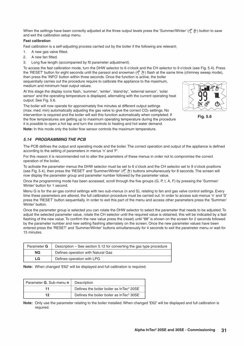
31Alpha InTec² 20SE and 30SE - Commissioning
When the settings have been correctly adjusted at the three output levels press the 'Summer/Winter' ( ) button to save and exit the calibration setup menu.
Fast calibration
Fast calibration is a self-adjusting process carried out by the boiler if the following are relevant;1. A new gas valve fitted.2. A new fan fitted.3. Long flue length (accompanied by f0 parameter adjustment).
To access the fast calibration mode, turn the DHW selector to 6 o'clock and the CH selector to 9 o'clock (see Fig. 5.4). Press the 'RESET' button for eight seconds until the parasol and snowman ( ) flash at the same time (chimney sweep mode), then press the 'INFO' button within three seconds. Once the function is active, the boiler sequentially carries out the procedure require to calibrate the appliance to the maximum, medium and minimum heat output values.
At this stage the display icons flash, 'summer', 'winter', 'stand-by', 'external sensor', 'solar sensor' and the operating temperature is displayed, alternating with the current operating heat output. See Fig. 5.6.
The boiler will now operate for approximately five minutes at different output settings (max. med. min) automatically adjusting the gas valve to give the correct CO2 settings. No intervention is required and the boiler will exit this function automatically when completed. If the flow temperatures are getting up to maximum operating temperature during the procedure it is possible to open a hot tap and turn the controls to heating and hot water demand.Note: In this mode only the boiler flow sensor controls the maximum temperature.
5.14 PROGRAMMING THE PCB
The PCB defines the output and operating mode and the boiler. The correct operation and output of the appliance is defined according to the setting of parameters in menus 'n' and 'F'.
For this reason it is recommended not to alter the parameters of these menus in order not to compromise the correct operation of the boiler.
To activate the parameter menus the DHW selector must be set to 6 o’clock and the CH selector set to 9 o’clock positions (see Fig. 5.4), then press the 'RESET' and 'Summer/Winter' ( ) buttons simultaneously for 8 seconds. The screen will now display the parameter group and parameter number followed by the parameter value.
Once the programming mode has been accessed, scroll through the five groups (G, P, t, A, F) by pressing the 'Summer/Winter' button for 1 second.
Menu G is for the air-gas control settings with two sub-menus (n and S), relating to fan and gas valve control settings. Every time these parameters are altered, the full calibration procedure must be carried out. In order to access sub-menus 'n' and 'S' press the 'RESET' button sequentially. In order to exit this part of the menu and access other parameters press the 'Summer/Winter' button.
Once the parameter group is selected you can rotate the DHW selector to select the parameter that needs to be adjusted. To adjust the selected parameter value, rotate the CH selector until the required value is obtained, this will be indicated by a fast flashing of the new value. To confirm the new value press the (reset) until “88” is shown on the screen for 2 seconds followed by the parameter number and new setting flashing alternately on the screen. Once the new parameter values have been entered press the 'RESET' and 'Summer/Winter' buttons simultaneously for 4 seconds to exit the parameter menu or wait for 15 minutes.
Fig. 5.6
Note: When changed 'E62' will be displayed and full calibration is required.
Description – See section 5.12 for converting the gas type procedure
Defines operation with Natural Gas
Defines operation with LPG
Parameter G
NG
LG
Description
Defines the boiler boiler as InTec2 20SE
Defines the boiler boiler as InTec2 30SE
Parameter G, Sub-menu n
11
12
Note: Only use the parameter relating to the boiler installed. When changed 'E62' will be displayed and full calibration is required.

32 Alpha InTec² 20SE and 30SE - Commissioning
Note: These must be set to the correct values relating to the boiler installed. When changed 'E62' will be displayed and full calibration is required. See Section 5.13.
Parameter Feature Description Range
0 - 99 %
0 - P2
0 - 99 %
0 - 7
0 - 7
0 - 9
0 - 1
-9 +9 °C
-
The maximum output of the boiler during DHW production as a percentage of the maximum available output
The minimum heat output of the boiler during DHW and CH production as a percentage of the available heat output
The maximum output of the boiler during CH production as a percentage of the maximum available output
Boiler functions/configurations when optional relay PCB is fitted0 = Off1 = Main zone control (with Climatic controller)2 = General alarm3 = CH phase active (external pump)4 = External gas valve power supply5 = Flow Smart enabled6 = Diverter valve enabled7 = When boiler pump active
Boiler functions/configurations when optional relay PCB is fitted0 = Off1 = General alarm2 = CH phase active (external pump)3 = External gas valve power supply4 = Secondary zone control (volt free switching across 57 & 58 on relay PCB contacts)5 = Heat pump function with dedicated controls6 = Alpha Trace heating cable enabled7 = When boiler pump active
Boiler functions/configurations when optional relay PCB is fitted0 = Off1 = Chiller remote activation (with Climatic controller)2 = General alarm3 = CH phase active (external pump)4 = External gas valve power supply5 = Heat pump function with dedicated controls6 = Activation of storage tank pump (with Climatic controller)7 = Main zone control (with Climatic controller)8 = Alpha Trace heating cable enabled9 = When boiler pump active
The pump can function in two ways.0 Intermittent - In Winter mode the pump is managed by the room thermostat or by the remote control1 Continuous - In Winter mode the pump is always on
If the reading of the external sensor is incorrect it is possible to offset the reading.(Over the value of +9 the display shows 'CE', for external control connection only used with system supervisor connection)
Not used on this boiler model
DHW max.
Min. outputDHW and CH
Heating max.
Relay 1(optional)
Relay 2(optional)
Relay 3(optional)
Pump functioning
External sensor correction
-
P0
P1
P2
P3
P4
P5
P6
P7
P8
Default
99 %
0 %
1
6
0
0
0
-
20SE - 99 %20SE (LPG) - 99 %
30SE - 99 %30SE (LPG) - 99 %
InTec2 20SEF0 parameter setting
InTec2 30SEF0 parameter setting
F0 = 012
(1275 rpm)42
(4200 rpm)41
(4100 rpm)39
(3950 rpm)
F0 = 113
(1300 rpm)44
(4450 rpm)43
(4350 rpm)39
(3950 rpm)
F0 = 213
(1350 rpm)47
(4700 rpm)46
(4600 rpm)39
(3950 rpm)
F0 = 014
(1400 rpm)61
(6100 rpm)60
(6000 rpm)37
(3700 rpm)
F0 = 114
(1425 rpm)63
(6300 rpm)62
(6250 rpm)37
(3700 rpm)
F0 = 214
(1450 rpm)64
(6400 rpm)63
(6300 rpm)37
(3700 rpm)
S1 (max. fan speed)
S1 (max. fan speed)
S0 (min. fan speed)
S2 (ignition fan speed)
Natural gasParameter G = NG
LPGParameter G = LG
Sub menu s
Fan speed set values according to boiler model and 'F0' parameter (flue setting)
Parameter G

33Alpha InTec² 20SE and 30SE - Commissioning
Parameter Feature Description Range
20 - 50 °C
(t0 + 5) + 85 °C
0 - 3
-
-
0 - 600 seconds(10 sec steps)
0 - 840 seconds(10 sec steps)
0 - 600 seconds (10 sec steps)
0 - 2
0 - 1
0 - 4
-
Set 3
1 - 9
1 - A3
0 - 25
0 - 2
-
Defines the minimum flow temperature set point
Defines the maximum flow temperature set point
Establishes the switch-off method in DHW mode (if Alpha diverter valve kit fitted) depending on the cylinder temperature0 Cylinder heating on Cylinder temp. = set point temp - 3°C Cylinder heating off Cylinder temp = set point temp1 Cylinder heating on Cylinder temp = set point temp - 2°C Cylinder heating off Cylinder = set point temp + 1°C2 Cylinder heating on Cylinder temp = set point - 10°C Cylinder heating off Cylinder temp = set point temp3 Cylinder heating on Cylinder temp = set point temp - 5°C Cylinder heating off Cylinder temp = set point temp2 - 3 are recommended with solar cylinder
Not used on this boiler model
Not used on this boiler model
Adjustable anti-cycling period
Adjustable time period for the burner to ramp up to maximum output in CH mode
Ignition response adjustment, ie underfloor type systems with slow acting actuator valves will need a delay to prevent boiler overheating occurring
Establishes the display lighting mode0 Automatic - The display lights up during use and dims after 15 secs of inactivity. In the event of an anomaly the display flashes.1 Low - The display is always lit with low intensity2 High - The display is always lit with high intensity
'Summer' mode0 - No information is displayed1 - DHW active, the display shows the flow temperature'Winter' mode0 - The display shows the set value of the CH selector1 - CH or DHW active, the display shows the flow temperature and when not active the display shows the set value of the CH selector
Defines the type of hydraulics in the boiler0 = Boiler flow switch (not used on this model)1 = Flow meter (not used on this model)2 = System boiler3 = Boost - pre-heat function (not used on this model)4 = Flow meter and boost function (not used on this model)
Not used on this boiler model
Defines the type of pump in the boiler
Max. pump speed
Min. speed setting *Should not be below 5
Defines the automatic pump speed control mode (see Section 2.4)0 PROPORTIONAL - ΔT = 0°C, pump head proportional to
heat output5 - 25 CONSTANT ΔT - ΔT = 5 - 25°C, the pump speed is
controlled automatically to keep a constant ΔT between heating flow and return.
Defines the length of the flue0 = < 4.5 m1 = 4.5 - 9.0 m2 = > 9.0 mIn the event of an alteration, anomaly 'E72' will be displayed and fast calibration is required. See Section 5.13.
Not used on this bolier model
CH set point min. temperature
CH set point max. temperature
DHW thermostat
-
-
CH ignitions timer
CH ramp timer
CH ignition delay from controls
request
Display lighting
Display information
Hydraulic model
-
Pump model
Max. pump speed
Min. pump speed
Automatic pump speed control
Equivalent flue length
-
T0
T1
T2
T3
T4
T5
T6
T7
T8
T9
A0
A1
A2
A3
A4
A5
F0
F1
Default
20
85
2
-
-
18(180 secs)
18(180 secs)
0
0
1
2
-
3
9*
5*
15
0
-

34
6 ROUTINE SERVICING
Alpha InTec² 20SE and 30SE - Routine Servicing
To ensure efficient operation of the boiler it is recommended that it is checked and serviced as necessary at regular intervals. The frequency of servicing will depend upon the particular installation conditions and usage, but in general once per year is required as a minimum.
It is the law that any service work must be carried out by a competent person, i.e. Gas Safe registered engineer.
Warning: Before servicing the boiler, isolate the electrical supply and close the boiler gas service cock. Allow the boiler to cool.
Always test for gas tightness after servicing any gas carrying components.
Always carry out electrical system checks i.e. Earth Continuity, Resistance to Earth, Short Circuit and Polarity with a suitable meter before and after servicing.
General
Please Note: During routine servicing, and after any maintenance or change of part of the combustion circuit, the following must be checked:
1. The integrity of the flue system and the flue seals, as described in Section 4.6 and 4.7.
2. The integrity of the boiler combustion circuit and relevant seals.
3. The operational (working) gas inlet pressure at maximum rate, as described in Section 5.7.
4. The combustion performance, as described below and in Section 5.7.
5. The air flow through the heat exchanger as described in Section 5.4.
Competence to carry out the check of combustion performance
Please Note: BS 6798:2009 Specification for installation and maintenance of gas-fired boilers of rated input not exceeding 70 kW net advises that:
1. The person carrying out a combustion measurement should have been assessed as competent in the use of a flue analyser and the interpretation of the results.
2. The flue gas analyser used should be one meeting the requirements of BS 7927 or BS-EN 50379-3 and be calibrated in accordance with the analyser manufacturers' requirements.
3. Competence can be demonstrated by satisfactory completion of the CPA1ACS assessment, which covers the use of electronic portable combustion gas analysers in accordance with BS 7967, Parts 1 to 4.
Combustion check
Connect the flue gas analyser to the flue gas sampling point as shown in Fig. 5.3.
Notes: 1. Prior to servicing, it is recommended that a flue gas analyser is used to measure the performance of the boiler (refer to Fig. 5.3 for the position of the flue sampling point). Refer to Section 5.7 Checking combustion. If the CO/CO2 ratio measured is greater than 0.003 or when other checks or comments from the customer have indicated that there may be problems, check the following:
Any flue gas recirculation in the flue system or boiler casing.
Any restrictions or blockages in the flue system.
The gas supply pressure and gas rate are correct.
If these are correct then cleaning of the burner and checking the electrode will be necessary. All Sections 6.1, 6.2, 6.3 and 6.4 must be carried out. After reassembling the boiler carry out a full calibration procedure (refer to Section 5.13). Repeat the flue gas analyser test and check that the CO/CO2 ratio is less than 0.003.
If the CO/CO2 ratio reading is still above 0.003, check again for flue gas recirculation, flue restrictions or blockage and insufficient gas supply pressure. If correct, repeat the procedure above (including full calibration) until you obtain a ratio reading of below 0.003.
If the combustion reading is greater than the acceptable value AND the integrity of the complete flue system and combustion circuit seals have been verified and the inlet gas pressure (and gas rate) have been verified. Please call our Technical Helpline.
2. If the CO/CO2 ratio measured is less than 0.003 and other checks and comments from the customer suggest there are no problems then only Section 6.1 and Section 6.3 paragraphs 1, 2 and 3 need to be carried out to allow a visual check of the components within the room sealed chamber.
6.1 IMPORTANT NOTES PRIOR TO SERVICING
1. Check the entire flue length and joints including the flue terminal outside. Ensure that all of the flue assembly has been installed correctly and there are no blockages.
2. Run the boiler and check the operation of its controls.
3. Ensure that all system connections and fittings are sound. Remake any joints and check the tightness of any fittings that may be leaking.

35Alpha InTec² 20SE and 30SE - Routine Servicing
4. Refill, vent and re-pressurise the system as necessary. (Refer to Commissioning, Section 5.1). If the system pressure exceeds 2.5 bar when operating at maximum temperature, the heating expansion vessel should
be checked and re-pressurised, if necessary.
Note: 1. Check the expansion vessel charge only when the system pressure is zero. 2. The expansion vessel pressure test point is accessible from on top at the top left side.
5. Check that the condensate trap drain pipe is connected and all joints are sound.
6. Check the air flow through the heat exchanger as described in Section 5.4.
7. Record details of the service in the Service Record at the back of these instructions.
6.2 CASING REMOVAL - Figs. 6.1, 6.2, 6.3 and 6.4
To facilitate boiler servicing and maintenance the casing can be completely removed as follows:
Case front panel - Fig. 6.2
3. Loosen the two screws 'D'.
4. Pull the front panel 'E' slightly towards you.
5. Release front 'E' from pins 'F' pulling it towards you while pushing it upwards at the same time.
Fig. 6.1
Fig. 6.2
Control panel cover - Fig. 6.1
1. Hinge down the control panel door, remove the two screw cover plugs 'A' and remove the screws 'B'.
2. Pull the front panel 'C' towards you and release it from its lower fixing.
B
A
1
B
A
2
1
3
D
3
D
E
5 5
F
F
4
4

36 Alpha InTec² 20SE and 30SE - Routine Servicing
Control panel - Fig. 6.3
6. Press the hooks on the side of the control panel (G).
7. Tilt the control panel (G) towards you.
Side panels - Fig. 6.4
8. Remove the screws 'H' securing the side panel 'I'. Lift the side panel and pull it forwards unhooking it from the rear panel (view 'A' in Fig. 6.4) Lower the panel out and away from the top cover.
Fig. 6.3
Fig. 6.4
7
G
G
6
6
6
6
IH
A
A
H
8
I
H
8
A
A
A
H
A
View A

37Alpha InTec² 20SE and 30SE - Routine Servicing
6.3 PREPARE FOR SERVICING - Fig. 6.5
1. Ensure the electrical supply is isolated and the gas supply is off.
2. Gain access by removing the control panel cover, case front panel and lowering the control panel as described in Section 6.2.
3. Remove the condensate trap assembly as described in Section 7.11.
4. Remove the electrode as described in Section 7.3 and check its condition.
5. Remove the three screws securing the fan air/gas manifold and remove the two spring clips at either end of the gas pipe, removing the pipe and manifold together.
6. Unscrew the flue sampling point cap and remove the complete fitting from the top of the case.
7. Disconnect the flue sensor wires and remove the lower retaining screw on the flue manifold assembly.
8. Pull down the flue manifold assembly and withdraw the complete assembly.
9. Disconnect the fan wire.
10. Unlatch the two clips 'A' in Fig. 6.5 securing the fan and burner cover and remove the complete assembly.
11. Disconnect the earth wire from the burner and lift the burner out of the heat exchanger.
Fig. 6.5
6.4 CLEANING THE ELECTRODE AND BURNER
1. Check the condition of the burner, using vacuum carefully clean the side not exposed to the flame (do not use compressed air or a brush). Do not clean the side exposed to the flame, it can easily be damaged.
2. Remove the electrode and check its condition. If it is in good condition, remove any oxide deposits using a fine abrasive paper. Replace it in the heat exchanger using
a new gasket. If it is necessary to replace the electrode ensure a new gasket is used and connect the lead to the PCB through the
grommet in the rear of the control panel.
6.5 CLEANING THE HEAT EXCHANGER
Cleaning the heat exchanger is only necessary if the air flow test pressure has reduced by more than 40% as described in Section 5.4.
Gain access and drain the boiler heating circuit as described in Sections 7.1 and 7.2.
1. Remove the condensate trap assembly as described in Section 7.11.
2. Remove the electrode as described in Section 7.3 and check its condition.
3. Remove the three screws securing the fan air/gas manifold and remove the two spring clips at either end of the gas pipe, removing the pipe and manifold together.
4. Unscrew the flue sampling point cap and remove the complete fitting from the top of the case.
5. Disconnect the flue sensor wires and remove the lower retaining screw on the flue manifold assembly.
6. Pull down the flue manifold assembly and withdraw the complete assembly.
Fan and burner cover
A
A
Earth wire
connection
Gas supply pipe
Electrode
Burner removed

38 Alpha InTec² 20SE and 30SE - Routine Servicing
7. Unplug the primary sensor and fan wires.
8. Unlatch the two clips 'A' in Fig. 6.5 securing the fan and burner cover and remove the complete assembly.
9. Disconnect the earth wire from the burner and lift the burner out of the heat exchanger.
10. Remove the retaining clips from the flow and return pipes at the heat exchanger and hydro block housing and remove the pipes.
11. Remove the two screws securing the bottom rear of the heat exchanger to the condensate sump.
12. Lift the heat exchanger up and forwards to release it from its fixing bracket and withdraw it from the boiler.
13. Remove the four screws securing the condensate sump to the heat exchanger and remove it.
14. With the correct cleaning tool, clean the heat exchanger, inserting the tool in the bottom of the heat exchanger between the pins in both directions to remove any deposits.
15. After cleaning, flush the heat exchanger from both sides with running water in order to remove any residue,
16. Reassemble in reverse order.
Note: The following items must be replaced with new ones:
• Burner seal
• Condensate tray seal
• Heating flow and return pipes 'O' rings
• Electrode gasket if removed
17. Check again the air flow through the heat exchanger as described in Section 5.4, recording the new pressure value and complete the service record at the back of these instructions,
6.6 RE-ASSEMBLE THE BOILER
1. Replace the burner seal ensuring it is located correctly around the burner edge.
2. Replace the burner ensuring it is located correctly in the heat exchanger and re-connect the earth wire.
3. Replace the burner cover and fan assembly securing with the two latches then re-connect the fan wire.
4. Replace the flue manifold assembly and secure to the condensate tray with the fixing screw. Re-connect the flue sensor wire.
5. Replace the flue sampling point connection to the boiler casing and flue manifold assembly using the foam seal previously removed. Replace the flue sampling point cap and secure it with the screw previously removed.
6. Replace the air/gas manifold to the fan (using the 'O' ring previously removed).
7. Replace the condensate trap and connection hoses. Partially fill the trap before replacing.
8. Check all the connections are sound and re-commission, Sections 5.3 and 5.8.
9. Raise the control panel and clip into place.
10. Place the front case panel in position and secure with the two screws previously removed.
11. Refit the control panel cover and secure in position with the two screws and cover plugs.
12. Carry out a full calibration procedure (refer to Section 5.13) if the burner and electrode have been cleaned or replaced.
13. Check the operation of the boiler. (Refer to Sections 5.5 and 5.6).
14. Return all controls to their original settings.

39Alpha InTec² 20SE and 30SE - Component Replacement
1 Boiler drain point
2 Gas valve
3 Condensate trap
4 System expansion vessel
5 Air / gas mixer
6 Primary temperature sensor
7 Manual air vent valve
8 Ignition / sensing electrode
9 Test points (air A) - (flue F)
10 Flue temperature sensor
11 Burner cover
12 Overheat thermostat
13 Primary heat exchanger
14 Fan
15 Primary pressure switch
16 Automatic air vent
17 Boiler pump
18 Safety valve (3 bar)
19 By-pass
20 Safety valve operation indicator
Fig. 7.1
1
7
6
10
11
12
13
14
15
16
17
18
19
20
2
3
8
5
8
9 F A
7 COMPONENT REPLACEMENT
To ensure correct and safe operation of the appliance, it is essential that any worn or failed components are replaced with only genuine Alpha spare parts. Use of non-genuine Alpha spares could invalidate your warranty and may pose a potential safety hazard.
It is the law that any service work must be carried out by a competent person, i.e. Gas Safe registered boiler engineer.
Warning: Before replacing any boiler components, isolate the electrical supply and close the boiler gas service cock. Allow the boiler to cool.
Always test for gas tightness before and after replacing any gas carrying components or disturbing any gas connections.
Always carry out electrical system checks i.e. Earth Continuity, Resistance to Earth, Short Circuit and Polarity with a suitable meter after servicing.
Check the operation of the boiler. (Refer to Sections 5.5 and 5.6). Ensure that all the controls are returned to their original settings.

40 Alpha InTec² 20SE and 30SE - Component Replacement
7.1 GENERAL ACCESS
Ensure the electrical supply is isolated and the gas supply is off.
Gain access by removing the control panel cover, case front panel and lowering the control panel as described in Section 6.2.
7.2 DRAINING THE BOILER - Figs. 2.2 and 4.4
Isolate the electricity supply and close the boiler gas service cock, see Fig. 4.4. Allow the boiler to cool.
1. Close the central heating flow and return valves, see Fig. 4.4.
2. Connect a suitable pipe to the drain point, see Figs. 4.4 and 6.7 and route it to a suitable container. Open the drain point.
Note: Some water will remain in the components and care must be taken when removing them.
7.3 IGNITION AND SENSING ELECTRODE - Fig. 7.1
Gain access as described in Section 7.1.
1. Unhook the ignition lead from the rear of the control panel, release the grommet and unplug the lead from the PCB.
2. Remove the two nuts securing the electrode to the front of the combustion chamber using an 8 mm socket and carefully withdraw the electrode.
3. Fit the new electrode with a new gasket and re-assemble in reverse order.
4. Test the boiler and carry out the full calibration as described in Section 5.13.
7.4 MAIN BURNER
1. Remove the burner as described in Routine Servicing, Section 6.3.
2. Re-assemble with a new burner as described in Routine Servicing, Section 6.5.
3. Test the boiler and carry out the full calibration as described in Section 5.13.
7.5 FAN - Fig. 7.1
Gain access as described in Section 7.1.
1. Remove the gas pipe to air/gas manifold retaining clip and unplug the fan wire from the fan.
2. Remove the fan inlet manifold to burner cover screws and lift the fan assembly upwards to unhook it from the gas pipe.
3. Remove the three venturi screws and transfer the venturi and seal to the new fan.
4. Remove the two fan inlet manifold screws and transfer the manifold and seal to the new fan.
5. Re-assemble in reverse order.
6. Test the boiler as described in Routine Servicing and carry out the fast calibration as described in Section 5.13.
7.6 FLUE TEMPERATURE SENSOR - Fig. 7.1
Gain access as described in Section 7.1.
1. Unplug the wire from the flue sensor.
2. Using a 13 mm spanner, unscrew the sensor from the flue outlet manifold.
3. Fit the new sensor and re-assemble in reverse order. Do not overtighten.
7.7 FUSE - Fig. 7.2
The fuse is located on the PCB.
1. Gain access to the PCB as described in Section 7.8.
2. Lift out and remove the fuse. Fit a 3.15 AF fuse as a replacement.
3. Re-assemble in reverse order.PCB fuse
PCB
Pressure gauge
Fig. 7.2

41Alpha InTec² 20SE and 30SE - Component Replacement
7.8 PCB - Fig. 7.2
Note: The replacement of the gas valve or PCB must be carried out by a Gas Safe registered engineer with the use of a flue analyser.
Gain access as described in Section 7.1.
1. Unhook the ignition lead from the rear of the control panel, release the grommet and unplug the lead from the PCB.
2. Remove the three retaining screws in the PCB cover and remove cover. See Fig. 7.2.
3. Remove the PCB retaining screws.
4. Release the retaining clips, lift the PCB from the control panel and unplug the wire connections.
5. To maintain the boiler parameter setting, remove the memory chip from the removed PCB and insert into the new PCB.
6. Re-assemble in reverse order. Refer to the wiring diagram in Section 8.1 for connections. When replacing the cover, ensure no wires are trapped and all wiring is secured. Secure with three screws - do not over
tighten.
7. Test the boiler and carry out the fast calibration as described in Section 5.13.
Note; If the original PCB memory chip is not used in the new PCB the boiler parameters will need to be set and full calibration procedure is required.
7.9 PRESSURE GAUGE - Fig. 7.2
Gain access to the boiler as described in Sections 7.1 and 7.2.
1. Withdraw the retaining clip securing the pressure gauge sensor (just to the left of the automatic air vent) and withdraw the sensor.
2. Remove the main cable grommet in the bottom panel and remove the sensor tube.
5. Depress the two lugs on the pressure gauge and pull it out of the control panel.
4. Fit the new gauge using a new 'O' ring on the connection if necessary.
5. Refill and pressurise the system. (Refer to Commissioning, Section 5.1).
7.10 GAS VALVE – BURNER INJECTOR
Note: The replacement of the gas valve or PCB must be carried out by a Gas Safe registered engineer with the use of a flue analyser.
Isolate the boiler gas supply and gain access as described in Section 7.1.
1. Disconnect the electrical plug from the gas valve.
2. Remove the gas pipe retaining clip from the top of the gas valve and remove the pipe.
3. Disconnect the gas valve union beneath the boiler.
4. Remove the two screws from beneath the boiler and lift out the valve assembly.
5. Unscrew the injector from the top of the gas valve and transfer the injector to the new gas valve using a new washer.
6. Fit the new assembly and re-assemble in reverse order and test for gas tightness.
7. Light the boiler. (Refer to Commissioning, Section 5.4).
8. Test the boiler and carry out the fast calibration as described in Section 5.13.
7.11 PRIMARY FLOW/RETURN TEMPERATURE SENSOR and OVERHEAT THERMOSTAT - Fig. 7.1
Gain access to the boiler as described in Section 7.1.
1. Unplug the wiring and unscrew the sensor using a 13 mm spanner.
2. Re-assemble in reverse order with a new sensor. Do not overtighten.
7.12 AUTOMATIC AIR VENT - Fig. 7.1
Gain access and drain the boiler heating circuit as described in Sections 7.1 and 7.2.
1. Turn the automatic air vent anticlockwise and lift it out.
2. Insert the new air vent using a new washer and turn it clockwise to lock it in position.
3. Refill and pressurise the system. (Refer to Commissioning, Section 5.1).

42 Alpha InTec² 20SE and 30SE - Component Replacement
7.13 PRIMARY HEAT EXCHANGER - Fig. 7.1
Gain access and drain the boiler heating circuit as described in Sections 7.1 and 7.2.
1. Remove the condensate trap assembly as described in Section 7.14.
2. Remove the electrode as described in Section 7.3 and check its condition.
3. Remove the three screws securing the fan air/gas manifold and remove the two spring clips at either end of the gas pipe, removing the pipe and manifold together.
4. Unscrew the flue sampling point cap and remove the complete fitting from the top of the case.
5. Disconnect the flue sensor wires and remove the lower retaining screw on the flue manifold assembly.
6. Pull down the flue manifold assembly and withdraw the complete assembly.
7. Disconnect the primary sensor and fan wires.
8. Unlatch the two clips 'A' in Fig. 6.5 securing the fan and burner cover and remove the complete assembly.
9. Disconnect the earth wire from the burner and lift the burner out of the heat exchanger.
10. Remove the retaining clips from the flow and return pipes at the heat exchanger and water manifold and remove the pipes.
11. Remove the two screws securing the bottom rear of the heat exchanger to the condensate sump.
12. Lift the heat exchanger up and forwards to release it from its fixing bracket and withdraw it from the boiler.
13. Transfer the condensate tray, the electrode previously removed, sensors, retaining latches ('A' in Fig. 6.5) to the new heat exchanger using new seals
14. Reassemble in reverse order.
Note: The following items must be replaced with new ones:
• Burner seal
• Condensate tray seal
• Heating flow and return pipes 'O' rings
• Electrode gasket Check the condition of all other seals before reassembling.
15. Check again the air flow through the heat exchanger as described in Section 5.4, recording the new pressure value and complete the service record at the back of these instructions,
7.14 CONDENSATE TRAP - Figs. 7.1 and 7.3
Gain access as described in Section 7.1.Note: Before removing the trap, ensure that the water from the trap can be contained to avoid spillage.
1. Pull the flue drain hose off the top of the condense trap, cut the cable tie and pull the rubber condense hose adapter out of the bottom of the boiler.
The cable tie is only to secure the adaptor during transit and installation, it is not required after removal.
2. Remove the trap fixing screw from the bottom of the boiler and turn the trap to the left to disconnect it from the expansion valve outlet pipe.
3. Rotate the trap in a slight backwards motion to disconnect it from the flue manifold, being careful not to spill any condense water, remove the trap from the boiler.
4. It is important to clean the trap every time the trap is removed to flush out any deposits from the collection bowl.
Note: Partially fill the trap before replacing.

43
7.15 PUMP HEAD - Fig. 7.3
Gain access and drain the boiler heating circuit as described in Sections 7.1 and 7.2.
1. Disconnect the two plugs from the pump.
2. Using a 4 mm Allen key remove the four socket head screws securing the pump head to the body.
3. Reassemble the new pump head in reverse order ensuring, re-connecting the two plugs.
4. Refill and pressurise the system. (Refer to Commissioning, Section 5.1).
7.16 PRIMARY PRESSURE SWITCH - Fig. 7.3
Gain access and drain the boiler heating circuit as described in Sections 7.1 and 7.2.
1. Disconnect the wiring from the pressure switch.
2. Withdraw the retaining clip on the left side of the switch and lift the switch upwards to remove.
3. Insert a new switch and re-assemble in reverse order.
When connecting the wiring to the new switch the polarity of the wires is not important.
7.17 SAFETY VALVE - Fig. 7.3
Gain access and drain the boiler heating circuit as described in Sections 7.1 and 7.2.
1. Disconnect the clear plastic tube from the pressure relief valve.
2. Remove the retaining clip securing the expansion relief valve and pull the valve forwards to remove.
3. Re-assemble in reverse order.
4. Refill and pressurise the system. (Refer to Commissioning, Section 5.1).
7.18 EXPANSION VESSEL - Fig. 7.1
Note: Check that the pressure of the new vessel is 1 bar before it is installed.
Gain access and drain the boiler heating circuit as described in Sections 7.1 and 7.2.
1. Remove the top side panel fixing screw.
2. Disconnect the copper pipe from the bottom of the vessel.
3. Remove the top fixing nut from the air valve.
4. Remove the bottom fixing screw and withdraw the vessel taking care not to spill any water into other boiler components.
5. Re-assemble in reverse order.
6. Refill and pressurise the system. (Refer to Commissioning, Section 5.1).
7.19 ALPHA CONTROLS (if fitted)
Refer to section 4.11 on the connection options for boiler controls.
Alpha InTec² 20SE and 30SE - Component Replacement
Fig. 7.3
Condensate trap
Gas valve
PCB cover
Primary pressure switch
Pump
Safety valve

44 Alpha InTec² 20SE and 30SE - Wiring Diagram
8.1 ILLUSTRATED WIRING DIAGRAM
8 WIRING DIAGRAM
Colour Code
Bk ......Black
Bl .......Blue
Br .......Brown
G ........Green
Gy ......Grey
G/Y ....Green/Yellow
Or.......Orange
R ........Red
V ........Violet
W .......White
Y ........Yellow
Component identification
A19 ..........Removable memory
B1 ............Flow sensor
B4 ............External sensor (optional)
B5 ............Return sensor
B10 ..........Flue sensor
B24 ..........Flow safety sensor
E3 ............Ignition and detection electrode
M1............Boiler pump
M20..........Fan
R8 ............Cylinder resistor
S5 ............System pressure switch
T1 ............Transformer
T2 ............Ignition unit
X70 ..........Safety thermostat low temperature jumper
Y1 ............Gas valve
CH SET+
1 6
Programmer clock(optional)
X21
X26
50 51 52 53 54 55 56 57 58
X20 Relay board(optional)
Remove link toconnect clock
Mains Supply220 V ~ 50 Hz
Remove linkto connect 220 Vroom thermostat
Roomthermostat(optional)
When an Alpha Climatic control is connected to terminals 41 and 44remove the links between terminal blocks 1 and 2
DHW SET+
R5 R6
Low voltageconnections
220 Vconnections
VV
E3
-UB
PWM
GND
HS
+UB
M20
BkOr
BlW
R
W BkBl Or R
BkBr
Y
WOr
BkR
Y1
OrR
WBk
1 2 3 4
S5
Or
Or
W
Or
RR
BlBl
W
Or
VV
B1 B24 B10
R WR W
B5
BlBl
Br BkBl BkBl R Bk
RBr
Br Or YW Y Bl
Bk
Bk
Bl
Br
Gy
W
W
R
Gy
Br
Bl
Bk
BlBr G/Y G/Y
Br
Br
Bl
Bl
G/Y
Bk
X1 X2 X4 X9X10
X11
X12
X13
X14
X15
X16
X6
X8
X5
R2
1
1
X7
A19
T1
T2Fuse
3.15 AF
N L 3 2 3 2 1 4 1 7 1
5
1
9
1
5
1
4
1
6
1
6
1
1 6L N A B 1 2 3 4 6 75
M1
Y BlBrBk Bk
PW
M
GN
D
OU
T
L N
Storage tankNTC sensor(optional)
3-way valve(optional)
AlphaClimatic Control
(optional)
X70
B4
R8
R Br Or YBl Bk Br W Y
21 40 41 44 41 14 15 38 39 38 48
CH
DHW
M
2
1
3 4 5Ch
1
Ch
2

45
9 ERROR CODES AND FAULT FINDING
9.1 CARRY OUT INITIAL FAULT FINDING CHECKS
In the event of a suspected functional fault with the boiler, carry out initial fault finding checks to establish the cause.1. Check the correct gas, electrical and water supplies are available at the boiler.2. Check the boiler system pressure is in the green area of the boiler pressure gauge.3. Check that any boiler controls fitted are working and in an 'ON' position.4. Carry out electrical supply and connection checks and check all fuses.Where an error code is displayed use the following tables to identify the fault and possible causes.
9.2 ERROR CODES AND FAULT FINDING
If any fault or anomaly persists, contact Alpha Heating Innovation Technical Helpline.
The history of errors can be viewed in the 'INFO' menu - d9
Alpha InTec² 20SE and 30SE - Error Codes and Fault Finding
Errorcode
Fault Fault description Possible causes
Gas supplyCheck ignition/sensing electrodeIgnition generator or leadGas valve operationCheck PCB and wire connectionsFlue restriction or blockage
Pump or restricted flow problemBlocked heat exchangerAir in heat exchanger
Blocked or restricted primary flowHeat exchanger air flow blockedFlue restrictionFlue sensor faultAir in primary heat exchanger
Gas valve lead connection faultFaulty gas valveFaulty PCB
Flow sensor wire connections or sensor faulty
DHW sensor wiring connection or sensor faulty
Refer to fault history codes (INFO menu d9)
Check expansion vessel pressure (1 bar)Leak in systemExpansion relief valve operatedPrimary pressure switch
Cylinder sensor wire connections or sensor faulty
Check the settings of the 'A' family parameters
Check fan wiring connectionsFan faultPCB fault
Check flame sensing electrode and leadElectrical short circuit on sensing wiresPCB fault
Flow sensor wire connections or sensor faulty
Check for jammed control panel buttonsCheck for jammed PCB buttons
Check sensor wiring and connectionsCheck sensor resistance
Remote control or receiver connection wiringDistance or interference of RF signalRemote control or receiver fault(Check batteries if using RF controller)
Ignition failure
Overheat boiler lockout
High flue temperature
Gas valve electricalconnection fault
CH flow sensor fault
DHW sensor fault
Max. number of resets
Primary system pressure low
Cylinder sensor fault
Incorrect configuration
Fan fault
Flame sensing fault
CH return sensor fault
Control panel button fault
Flue sensor fault
Loss of communication with external control (Alpha Climatic)
01
02
03
04
05
06
08
10
12
15
16
20
23
24
29
31
Flame not detected during ignition sequence
Overheat sensor has activated
Flue sensor intervention (flue temperature too high)
Gas valve wiring circuit fault detected
Incorrect flow sensor resistance value
DHW sensor resistance value is incorrect
Maximum number of resets reached (5)
Primary pressure switch has operated
Incorrect cylinder sensor resistance value
Incorrect hydraulic configurationThere is an inconsistency between the settings and signals received from the PCB
Fan wiring fault or fan faulty
False flame detectionFlame detected but gas valve is not open
Incorrect return sensor resistance value(10 - 12 KΩ at room temperature)
Control panel button stuck in the on position
Flue sensor resistance out of range
Loss of connection between the boiler and Alpha Climatic control unit

46 Alpha InTec² 20SE and 30SE - Error Codes and Fault Finding
Errorcode
Fault Fault description Possible causes
BUS connection fault
Low supply voltage
Loss of flame rectification
Loss of flame rectification
Safety lock outLow supply voltage
High flow NTC and return NTC temperature difference detected
Optional external safety sensor intervention
Reduced burneroutput
Climatic RF communication fault
Mains supply voltage frequency block
Pump fault
Air in the pump
Full boiler calibration required
Fast calibration required
High flow NTC and safety NTC difference detected
Safety flow sensor anomaly
Anomaly on the gas valve control
36
37
38
43
44
45
46
47
51
59
60
61
62
72
73
74
777879
Check mains power supplyCheck for bad cable connections etc
Check flame sensing electrode and leadCheck for flue gas recirculationCheck the gas valveCheck flue system and terminationCheck gas supply/working pressureCheck/adjust combustion settings
Check as above for error code 38
Check external control (room thermostat) requestsRapid on/off tap requests
Check the primary flow is sufficientCheck the pump settings are appropriate for the system requirementsFaulty return sensors (incorrect readings)
Check external sensor and cable are not damaged or wetCheck continuity of external sensor and circuitCheck connections 14 and 15 on connection panel
Air in heat exchangerRestricted primary flowHeat exchanger air flow blockedFlue restrictionFlue sensor faultPump fault
Batteries require replacing
Check mains power supplyFaulty PCB
Check the pump operation, it may be necessary to free the pump shaft (refer to Section 2.4)Check the pump wiringReplace the pump
Check Flow and Return valves are openCheck for correct system pressureCheck the system is purged properly
Carry out full calibration process as described in Section 5.13
Carry out fast calibration process as described in Section 5.13
Faulty flow or safety NTC sensorCheck resistance reading on the sensorsPoor system circulation or blockage
Faulty safety NTC sensorCheck resistance reading on sensorReplace the safety NTC sensor
Check the electrode condition, replace if necessaryCheck the inlet gas pressure is correct and carry out a full calibration process as described in Section 5.13If the fault persists replace gas valve
Not used on this model
Insufficient supply voltage to operate boiler
Flame detected but signal lost. Ignition retries after fan purge
Repeated loss of flame signal during operationThis fault can occur if the flue is exposed to high wind conditions (shown as E38 in the fault code history in the INFO menu)
The boiler has attempted to fire repeatedly for the maximum time limit
A too high ΔT between CH flow and return sensors has been detectedThe heat output is limited to prevent damage to the heat exchangerWhen the ΔT returns to proper level the boiler restarts working normally
No continuity on external sensor circuitCheck link is present in external connections 14 and 15 or if fitted external safety device has activated
Flue thermostat has sensed high flue gastemperature (110°C) and reduced the burner output to prevent damageIf the temperature continues to rise the boiler will lock out and E03 will be displayed
Error between communication of the Climatic transmitter and boiler receiver
The PCB detects an incorrect mains supply voltage frequency
The pump is stuck or there is an electrical pump fault
Restricted CH flow due to air or a circuit restriction
This may occur when the PCB is replaced or if the parameters are altered in the air/gas section
The PCB detects that some parameters have been altered
The board detects an anomaly in the temperature readings difference between the flow NTC and safety NTC sensors
The PCB detects an anomaly on the safety NTC sensor
An anomaly on the gas valve control is detected

47Alpha InTec² 20SE and 30SE - Error Codes and Fault Finding
Errorcode
Fault Fault description Possible causes
Check gas valve electrical connectionCheck gas valve operationReplace gas valve and/or PCB
If normal conditions are restored the boiler restarts without having to be resetCheck all gas isolation valves are fully openIs the gas supply working pressure is correctCheck gas valve operation
Check PCB and gas valve electrical connectionsReplace PCB
Check as above for error code 87
Check the flue system is clear with no flue gas recirculationCheck elecrode condition, replace if necessaryCheck burner is clean and correctly earthedCarry out a full calibration process as described in Section 5.13If fault persists replace gas valve and/or PCB
Check as above for error code 89
Carry out a full calibration process as described in Section 5.13If fault persists replace gas valve and/or PCB
Check as above for error code 89
Check as above for error code 89
Check the inlet gas pressure and gas rate are correctCheck the flue system is clear with no flue gas recirculationCheck elecrode condition, replace if necessaryCheck burner is clean and correctly earthedCarry out a full calibration process as described in Section 5.13If fault persists replace gas valve and/or PCB
Check the electrode condition and lead, replace if necessaryCheck the burner is clean and correctly earthedCarry out full calibration process as described in Section 5.13If the fault persists replace the PCB
Check flue and air circuits are clearCheck fan function
Reset the boiler power supplyReplace the PCB
Press the boiler 'RESET' buttonReset the boiler power supplyReplace the PCB
Check the flow and DHW sensor resistance is within rangeCheck the parameters are correctly set forboiler model
A fault has occurred on the PCB function that controls the gas valve
A low supply pressure is detected on the gas line. As a result the appliance output is limited and the error code is displyed
A malfunction of one of the components that control the gas valve has been detected
A malfunction of one of the components that control the gas valve has been detected
A malfunction of one of the components of the air/gas circuit - the flame is unstable
The flame signal is beyond the adjustment range required for an extended period of time
The flame signal is lost repeatedly during ignition
The system has reached the maximimum possible correction limit
The flame signal is beyond the adjustment range required for a limited period of time
The anomaly is reported due to issues in the combustion circuit
Discontinuity is detected in the flame signal due to one of the components of the air/gas circuit
This occurs in the event an obstruction or restriction is detected in the flue system
The maximum number of software errors possible has been reached
A boiler anomaly has been detected
Sensor or parameter setting out of range
Block - gas valve driver issue
Combustion faultBoiler operating in reduced output mode
Block - gas valve control
Block - gas valve control
Flame signal unstable
Flame signal beyond limit
Block - flame signal lost during ignition
Fan speed max. correction
Flame signal beyond limit
Anomaly due to combustion issues
Flame signal discontinuous
Flue or air restriction detected
Block - max. number of software errors
General block
Reading out of range
80
84
87
88
89
90
91
92
93
94
95
96
98
99
- -

48 Alpha InTec² 20SE and 30SE - Short Parts List
10 SHORT PARTS LIST
Description Alpha Pt. No. Qty.
1
1
1
1
1
1
1
1
1
1
1
1
1
1
1
1
1
1
1
1
1
1
1
1
1
1
1
1
1
1
1
1
1
1
1
1
1
Pressure gauge
Condensate trap with seals
Bottom condensate trap connection
Flue, primary flow/return and safety sensor
Electrode with seal
Flue turret with seals
Pump head motor
Primary heat exchanger assembly
Burner with seal
Pressure switch
Main PCB
Safety valve 3 bar
Gas valve with washers
Automatic air vent with 'O'-ring seal
Flue manifold pipe assembly and seals
Relief valve to condensate connecting pipe
Expansion vessel
Fan
Burner seal
Flue sampling point cap
Primary heat exchanger vent
Complete boiler seal kit
Hydraulic circuit seal kit
Complete heat exchanger seal kit
Air/Gas intake seal kit
Flue circuit seal kit
Bottom heat exchanger sump assembly
Air/Gas mixer manifold - 20SE
Air/Gas mixer manifold - 30SE
Gas pipe to fan manifold
Gas pipe 'O' ring
Clip - Flow/return pipe to heat exchanger
Clip - Gas pipe connections
Boiler wall bracket
Boiler connection kit
Boiler accessory box complete
Wall template
1.034600
3.024821
1.023581
1.033784
3.026147
3.025218
1.038162
3.025194
3.025189
1.027277
3.026086
1.028561
3.025191
1.027110
3.025440
1.037890
1.034098
3.025195
1.031019
3.025820
1.025730
3.025322
3.025323
3.025326
3.025324
3.025325
3.025435
1.035805
1.035806
1.037823
1.037816
1.026763
1.020393
2.015350
3.025335
3.025336
1.035155

49Alpha InTec² 20SE and 30SE - This Page Intenionally Blank

50
11 ENERGY CLASSIFICATION
The values in the following tables refer to the maximum heating output.
Model(s): InTec² 20SE
Condensing boiler: YES
Low-temperature boiler: NO
B1 boiler: NO
Cogeneration space heater: NO Equipped with a supplementary heater: NO
Combination heater: YES
Item Symbol Value Unit Item Symbol Value Unit
Rated heat output Pn 18 kWSeasonal space heating energy efficiency
ηs 92 %
For boiler space heaters and boiler combination heaters: useful heat output
For boiler space heaters and boiler combination heaters: Useful efficiency
At rated heat output and high temperature regime (*)
P4 18.0 kWAt rated heat output and high temperature regime (*)
η4 87.7 %
At 30% of rated heat output and low temperature regime (**)
P1 5.4 kWAt 30% of rated heat output and low temperature regime (**)
η1 97.4 %
Auxiliary electricity consumption Other items
At full load elmax 0.022 kW Standby heat loss Pstby 0.072 kW
At part load elmin 0.012 kW Ignition burner power consumption Pign 0.000 kW
In standby mode PSB 0.005 kW Emissions of nitrogen oxides NOX 18mg / kWh
For combination heaters:
Declared load profile Water heating energy efficiency ηWH %
Daily electricity consumption Qelec kWh Daily fuel consumption Qfuel kWh
Contact details Alpha Therm Ltd., Nepicar House, Wrotham Heath, Kent. TN15 7RS
(*) High temperature regime means 60°C return temperature at heater inlet and 80°C feed temperature at heater outlet.(**) Low temperature means for condensing boilers 30°C, for low-temperature boilers 37°C and for other heaters 50°C return temperature.
Model(s): InTec² 30SE
Condensing boiler: YES
Low-temperature boiler: NO
B1 boiler: NO
Cogeneration space heater: NO Equipped with a supplementary heater: NO
Combination heater: YES
Item Symbol Value Unit Item Symbol Value Unit
Rated heat output Pn 28 kWSeasonal space heating energy efficiency
ηs 92 %
For boiler space heaters and boiler combination heaters: useful heat output
For boiler space heaters and boiler combination heaters: Useful efficiency
At rated heat output and high temperature regime (*)
P4 28.0 kWAt rated heat output and high temperature regime (*)
η4 87.7 %
At 30% of rated heat output and low temperature regime (**)
P1 8.4 kWAt 30% of rated heat output and low temperature regime (**)
η1 97.4 %
Auxiliary electricity consumption Other items
At full load elmax 0.047 kW Standby heat loss Pstby 0.072 kW
At part load elmin 0.016 kW Ignition burner power consumption Pign 0.000 kW
In standby mode PSB 0.005 kW Emissions of nitrogen oxides NOX 20mg / kWh
For combination heaters:
Declared load profile Water heating energy efficiency ηWH %
Daily electricity consumption Qelec kWh Daily fuel consumption Qfuel kWh
Contact details Alpha Therm Ltd., Nepicar House, Wrotham Heath, Kent. TN15 7RS
(*) High temperature regime means 60°C return temperature at heater inlet and 80°C feed temperature at heater outlet.(**) Low temperature means for condensing boilers 30°C, for low-temperature boilers 37°C and for other heaters 50°C return temperature.
11.1 TECHNICAL PARAMETERS FOR MIXED BOILERS (IN COMPLIANCE WITH REGULATION 813/2013)
Alpha InTec² 20SE and 30SE - Energy Classification

51
InTec² 20SE
Parameter value
Yearly energy consumption for the hea-ting function (QHE)
56.3 GJ
Yearly electricity consumption for the domestic hot water function (AEC)
Yearly fuel consumption for the domestic hot water function (AFC)
Seasonal room heating yield (ηs) 92 %
Domestic hot water production yield (ηwh)
11.2 PRODUCT DATA SHEET (IN COMPLIANCE WITH REGULATION 811/2013)
Parameter value
Yearly energy consumption for the hea-ting function (QHE)
87.4 GJ
Yearly electricity consumption for the domestic hot water function (AEC)
Yearly fuel consumption for the domestic hot water function (AFC)
Seasonal room heating yield (ηs) 92 %
Domestic hot water production yield (ηwh)
Alpha InTec² 20SE and 30SE - Energy Classification
InTec² 30E
A
A
++
+
A
B
C
D
E
F
G
45 dB
InTec² 20 SE
kW 18
A
A
A
++
+
A
B
C
D
E
F
G
50 dB
InTec² 30 SE
kW 28
A

52 Alpha InTec² 20SE and 30SE - Energy Classification
Seasonal space heating energy efficiency of boiler
1
%Temperature controlFrom fiche of temperaturecontrol
Supplementary boilerFrom fiche of boiler
Supplementary heat pumpFrom fiche of heat pump
Solar contribution AND Supplementary heat pump
Select smaller value
Boiler and supplementary heat pump installed with low temperature heat emitters at 35°C?
From fiche of heat pump
The energy efficiency of the package of products provided for in this fiche may not correspond to its actual energy efficiency once installed in a building, as the efficiency is influenced by further factors such as heat loss in the distribution system and the dimensioning of the products in relation to building size and characteristics.
Seasonal space heating energy efficiency of package
Seasonal space heating energy efficiency class of package
Solar contributionFrom fiche of solar device
Class I = 1 %, Class II = 2 %,Class III = 1.5 %, Class IV = 2 %,Class V = 3 %, Class VI = 4 %,Class VII = 3.5 %, Class VIII = 5 %
2
%+
3
%±
Seasonal space heating energy afficiency (in %)
( - ‘I’ ) x 0,1 =
( - ‘I’ ) x ‘II’ =
0.5 x O 0.5 x =
+ ( 50 x ‘II’ ) =
4
5
6
7
4 5
%
%
%
%
+
+
-
Collector size (in m2)
Tank volume (in m3)
Collector efficiency (in %)
Tank ratingA* = 0.95, A = 0.91B = 0.86, C = 0.83D-G = 0.81
( ‘III’ x + ‘IV’ x ) x (0.9 x ( / 100) x =
Seasonal space heating energy afficiency (in %)
G F E D C B A A+++A++A+
< 30 % ≥ 30 % ≥ 34 % ≥ 36 % ≥ 75 % ≥ 82 % ≥ 90 % ≥ 98 % ≥ 125 %≥ 150 %
%7
‘I’
11.3 FACSIMILE FOR FILLING IN ROOM HEATING SYSTEM ASSEMBLY CHART

53
Parameter InTec² 20SE InTec² 30SE
‘I’ 92 92
‘II’ * *
‘III’ 1.48 0.95
‘IV’ 0.58 0.37
11.5 PARAMETERS FOR FILLING IN ASSEMBLY CHART
* To be established by means of table 5 of Regulation 811/2013 in case of “assembly” including a heat pump to integrate the boiler. In this case the boiler must be considered as the main appliance of the assembly.
Seasonal space heating energy efficiency of boiler
1
%
Supplementary heat pumpFrom fiche of heat pump
Solar contribution AND Supplementary heat pump
Select smaller value
Boiler and supplementary heat pump installed with low temperature heat emitters at 35°C?
From fiche of heat pump
The energy efficiency of the package of products provided for in this fiche may not correspond to its actual energy efficiency once installed in a building, as the efficiency is influenced by further factors such as heat loss in the distribution system and the dimensioning of the products in relation to building size and characteristics.
Seasonal space heating energy efficiency of package
Seasonal space heating energy efficiency class of package
Solar contributionFrom fiche of solar device
2
%+
3
%±( - ______ ) x 0,1 =
( - _____ ) x _______ =
0.5 x O 0.5 x =
4
5
6
7
4 5
%
%
%
%
+
+
-
Collector size (in m2)
Tank volume (in m3)
Collector efficiency (in %)
Tank ratingA* = 0.95, A = 0.91B = 0.86, C = 0.83D-G = 0.81
( ____ x + ____ x ) x (0,9 x ( / 100) x =
G F E D C B A A+++A++A+
< 30 % ≥ 30 % ≥ 34 % ≥ 36 % ≥ 75 % ≥ 82 % ≥ 90 % ≥ 98 % ≥ 125 %≥ 150 %
%7
+ ( 50 x ______ ) =
____
11.4 ROOM HEATING SYSTEM ASSEMBLY CHART
Class I = 1 %, Class II = 2 %,Class III = 1.5 %, Class IV = 2 %,Class V = 3 %, Class VI = 4 %,Class VII = 3.5 %, Class VIII = 5 %
Temperature controlFrom fiche of temperaturecontrol
Supplementary boilerFrom fiche of boiler
Seasonal space heating energy afficiency (in %)
Seasonal space heating energy afficiency (in %)
Alpha InTec² 20SE and 30SE - Energy Classification

54
Water heating energy efficiency of combination heater
Water heating energy efficiency of package under average climate
Water heating energy efficiency class of package under average climate
Water heating energy efficiency under colder and warmer climate conditions
Colder: - 0.2 x =
Warmer : + 0.4 x =
Declared load profile:
Solar contributionFrom fiche of solar device
1
%_____
2
%+( 1.1 x _____ - 10 % ) x _____ - ____ - ______ =
Auxiliary electricity
3
%
G F E D C B A A+++A++A+
< 27 %
< 27 %
< 27 %
< 28 %
≥ 27 %
≥ 27 %
≥ 27 %
≥ 28 %
≥ 30 %
≥ 30 %
≥ 30 %
≥ 32 %
≥ 33 %
≥ 34 %
≥ 35 %
≥ 36 %
≥ 36 %
≥ 37 %
≥ 38 %
≥ 40 %
≥ 39 %
≥ 50 %
≥ 55 %
≥ 60 %
≥ 65 %
≥ 75 %
≥ 80 %
≥ 85 %
≥ 100 %
≥ 115 %
≥ 123 %
≥ 131 %
≥ 130 %
≥ 150 %
≥ 160 %
≥ 170 %
≥ 163 %
≥ 188 %
≥ 200 %
≥ 213 %
M
L
XL
XXL
3 2
3 2
%
%
The energy efficiency of the package of products provided for in this fiche may not correspond to its actual energy efficiency once installed in a building, as the efficiency is influenced by further factors such as heat loss in the distribution system and the dimensioning of the products in relation to building size and characteristics.
Parameter InTec² 20SE InTec 30SE
‘I’
‘II’ * *
‘III’ * *
11.7 PARAMETERS FOR FILLING IN DHW PACKAGE ASSEMBLY CHART
* To be determined according to Regulation 811/2014 and transient calculation methods as per Notice of the European Community no. 207/2014.
11.6 DOMESTIC HOT WATER PRODUCTION SYSTEM ASSEMBLY CHART
Alpha InTec² 20SE and 30SE - Energy Classification

55
Water heating energy efficiency of combination heater
Water heating energy efficiency of package under average climate
Water heating energy efficiency class of package under average climate
Water heating energy efficiency under colder and warmer climate conditions
Colder : - 0.2 x =
Warmer : + 0.4 x =
Declared load profile:
Solar contributionFrom fiche of solar device
1
%‘I’
2
%+( 1.1 x ‘I’ - 10 % ) x ‘II’ - ‘III’ - ‘I’ =
Auxiliary electricity
3
%
G F E D C B A A+++A++A+
< 27 %
< 27 %
< 27 %
< 28 %
≥ 27 %
≥ 27 %
≥ 27 %
≥ 28 %
≥ 30 %
≥ 30 %
≥ 30 %
≥ 32 %
≥ 33 %
≥ 34 %
≥ 35 %
≥ 36 %
≥ 36 %
≥ 37 %
≥ 38 %
≥ 40 %
≥ 39 %
≥ 50 %
≥ 55 %
≥ 60 %
≥ 65 %
≥ 75 %
≥ 80 %
≥ 85 %
≥ 100 %
≥ 115 %
≥ 123 %
≥ 131 %
≥ 130 %
≥ 150 %
≥ 160 %
≥ 170 %
≥ 163 %
≥ 188 %
≥ 200 %
≥ 213 %
M
L
XL
XXL
3 2
3 2
%
%
The energy efficiency of the package of products provided for in this fiche may not correspond to its actual energy efficiency once installed in a building, as the efficiency is influenced by further factors such as heat loss in the distribution system and the dimensioning of the products in relation to building size and characteristics.
11.8 FACSIMILE FOR FILLING IN DOMESTIC HOT WATER PRODUCTION SYSTEM ASSEMBLY CHART
Alpha InTec² 20SE and 30SE - Energy Classification

This Commissioning Checklist is to be completed in full by the competent person who commissioned the boiler as a means of demonstrating
compliance with the appropriate Building Regulations and then handed to the customer to keep for future reference.
Failure to install and commission according to the manufacturer’s instructions and complete this Benchmark Commissioning Checklist will invalidate the
warranty. This does not affect the customer’s statutory rights.
GAS BOILER SYSTEM COMMISSIONING CHECKLIST
Customer name: Telephone number:
Address:
Boiler make and model:
Boiler serial number:
Commissioned by (PRINT NAME): Gas Safe register number:
Company name: Telephone number:
Company address:
Commissioning date:
To be completed by the customer on receipt of a Building Regulations Compliance Certifcate*
Building Regulations Notifcation Number (if applicable):
CONTROLS (tick the appropriate boxes)
Time and temperature control to heatingRoom thermostat and programmer/timer Programmable room thermostat
Load/weather compensation Optimum start control
Time and temperature control to hot water Cylinder thermostat and programmer/timer Combination Boiler
Heating zone valves Fitted Not required
Hot water zone valves Fitted Not required
Thermostatic radiator valves Fitted Not required
Automatic bypass to system Fitted Not required
Boiler interlock Provided
ALL SYSTEMS
The system has been fushed and cleaned in accordance with BS7593 and boiler manufacturer’s instructions Yes
What system cleaner was used?
What inhibitor was used? Quantity litres
Has a primary water system flter been installed? Yes No
CENTRAL HEATING MODE measure and record:
Gas rate m³/hr OR ft³/hr
Burner operating pressure (if applicable) mbar OR Gas inlet pressure mbar
Central heating fow temperature °C
Central heating return temperature °C
COMBINATION BOILERS ONLY
Is the installation in a hard water area (above 200ppm)? Yes No
If yes, and if required by the manufacturer, has a water scale reducer been ftted? Yes No
What type of scale reducer has been ftted?
DOMESTIC HOT WATER MODE Measure and Record:
Gas rate m³/hr OR ft³/hr
Burner operating pressure (at maximum rate) mbar OR Gas inlet pressure at maximum rate mbar
Cold water inlet temperature °C
Hot water has been checked at all outlets Yes Temperature °C
Water fow rate I/min
CONDENSING BOILERS ONLY
The condensate drain has been installed in accordance with the manufacturer’s instructions and/or BS5546/BS6798 Yes
ALL INSTALLATIONS
Record the following:At max. rate: CO ppm AND CO/CO
²Ratio
At min. rate: (where possible) CO ppm AND CO/CO²
Ratio
The heating and hot water system complies with the appropriate Building Regulations Yes
The boiler and associated products have been installed and commissioned in accordance with the manufacturer’s instructions Yes
The operation of the boiler and system controls have been demonstrated to and understood by the customer Yes
The manufacturer’s literature, including Benchmark Checklist and Service Record, has been explained and left with the customer Yes
Commissioning Engineer’s Signature
Customer’s Signature
(To confrm satisfactory demonstration and receipt of manufacturer’s literature)
© Heating and Hotwater Industry Council (HHIC) www.centralheating.co.uk
All installations in England and wales must be notified to Local Authority Building Control (LABC) either directly or through a
Competent Persons Scheme. A Building Regulations Compliance Certificate will then be issued to the customer.
*
It is recommended that your heating system is serviced regularly and that the appropriate Service Interval Record is completed.
Service Provider
Before completing the appropriate Service Record below, please ensure you have carried out the service as described in the manufacturer’s instructions.
Always use the manufacturer’s specifed spare part when replacing controls.
SERVICE RECORD
SERVICE 01 Date:
Engineer name:
Company name:
Telephone No:
Gas safe register No:
Record:At max. rate: CO ppm AND CO
²%
At min. rate: (Where Possible) CO ppm AND CO²
%
Comments:
Signature
SERVICE 02 Date:
Engineer name:
Company name:
Telephone No:
Gas safe register No:
Record:At max. rate: CO ppm AND CO
²%
At min. rate: (Where Possible) CO ppm AND CO²
%
Comments:
Signature
SERVICE 03 Date:
Engineer name:
Company name:
Telephone No:
Gas safe register No:
Record:At max. rate: CO ppm AND CO
²%
At min. rate: (Where Possible) CO ppm AND CO²
%
Comments:
Signature
SERVICE 04 Date:
Engineer name:
Company name:
Telephone No:
Gas safe register No:
Record:At max. rate: CO ppm AND CO
²%
At min. rate: (Where Possible) CO ppm AND CO²
%
Comments:
Signature
SERVICE 05 Date:
Engineer name:
Company name:
Telephone No:
Gas safe register No:
Record:At max. rate: CO ppm AND CO
²%
At min. rate: (Where Possible) CO ppm AND CO²
%
Comments:
Signature
SERVICE 06 Date:
Engineer name:
Company name:
Telephone No:
Gas safe register No:
Record:At max. rate: CO ppm AND CO
²%
At min. rate: (Where Possible) CO ppm AND CO²
%
Comments:
Signature
SERVICE 07 Date:
Engineer name:
Company name:
Telephone No:
Gas safe register No:
Record:At max. rate: CO ppm AND CO
²%
At min. rate: (Where Possible) CO ppm AND CO²
%
Comments:
Signature
SERVICE 08 Date:
Engineer name:
Company name:
Telephone No:
Gas safe register No:
Record:At max. rate: CO ppm AND CO
²%
At min. rate: (Where Possible) CO ppm AND CO²
%
Comments:
Signature
SERVICE 09 Date:
Engineer name:
Company name:
Telephone No:
Gas safe register No:
Record:At max. rate: CO ppm AND CO
²%
At min. rate: (Where Possible) CO ppm AND CO²
%
Comments:
Signature
SERVICE 10 Date:
Engineer name:
Company name:
Telephone No:
Gas safe register No:
Record:At max. rate: CO ppm AND CO
²%
At min. rate: (Where Possible) CO ppm AND CO²
%
Comments:
Signature

9 Alpha InTec² 20SE and 30SE This Page Intentionally Blank
10 OPTIONAL BOILER CONTROLS (if fitted)
There is a range of controls available from Alpha to operate your boiler. In addition to the items listed below the Alpha InTec² boilers are compatible with most controls available on the market. However to get the most comfort and efficiency from your boiler we recommend the Alpha Climatic controls with enhanced remote boiler functions and efficiency control.
Please refer to the instructions provided with the controls for further information on their setting and use.
9 BENCHMARK COMMISSIONING and SERVICING
It is a requirement that the boiler is installed and commissioned to the manufacturers instructions and the data fields on the commissioning checklist completed in full.
To instigate the boiler guarantee the boiler needs to be registered with the manufacturer within one month of the installation.
To maintain the boiler guarantee it is essential that the boiler is serviced annually by a Gas Safe registered engineer who has been trained on the boiler installed. The service details should be recorded on the Benchmark Service Interval Record and left with the householder.
8Alpha InTec² 20SE and 30SE
Available Alpha controls:
7 day digital heating clock- two channel (boiler mounted) ..........................................................................Part No.6.1000220
Alpha Comfort 7 day wireless programmable room thermostat - two channel (boiler mounted receiver) ..Part No.3.022142
*Alpha Climatic wired programmable boiler energy manager (boiler mounted) .........................................Part No. 3.022144
*Alpha Climatic wireless programmable boiler energy manager (boiler mounted receiver) .......................Part No. 3.022143
*External weather compensation probe .....................................................................................................Part No. 3.022383
Alpha System diverter valve kit ..................................................................................................................Part No. 3.022382
Optional boiler controlled condensate trace heating kit ..............................................................................Part No. 6.5500000
* These controls can only be used in conjunction with the Alpha System diverter valve kit.

5 Alpha InTec² 20SE and 30SE
8 GAS SAFETY REGULATIONS
1. BOILER LOCATION
Always ensure the following clearances are available around the casing of the boiler:-
Top: (horizontal flue) 235 mm, Top: (vertical flue) 150 mm, Bottom: 150 mm, Bottom: (with Jig) 250 mm,
Each side: 5 mm, Front: 450 mm
Do not store any other articles in a cupboard containing the boiler and never place any clothing or combustible material on or near the boiler or flue pipe.2. FLUE TERMINAL
The terminal on the outside wall must not be allowed to be obstructed. If it is damaged, in any way, turn the boiler off and contact your Service Engineer.
Note: The Alpha InTec boilers are high efficiency condensing boilers and when operating vapour will be emitted from the terminal. This is safe and quite normal.3. MAINS FAILURE
In the event of an electrical supply failure the boiler will not operate. When the supply is restored, the boiler will return to normal operation. Remember to reset any controls, if fitted, when the supply is restored.
4. CLEANINGUse only a damp cloth and mild detergent to clean the boiler outer casing. Do not use abrasive cleaners.5. SERVICING
To maintain efficient and safe operation of your boiler, routine annual servicing is essential.
For advice on servicing contact:- The Alpha Helpline: 0844 871 8764.6. GAS LEAK
If a fault or gas leak is suspected, turn off the gas supply. Do not touch any electrical switches, do not smoke and extinguish all naked flames. Contact the National Gas Emergency Service immediately on 0800 111 999.7. ELECTRICAL SUPPLY
The boiler requires a 230/240 V ~ 50 Hz supply, fused at 3 A.To connect a plug:-
The colour of the wires in the mains lead of the boiler may not correspond with the coloured markings identifying the terminals in your plug. In this case proceed as follows:-
The wire coloured green and yellow must be connected to the terminal in the plug that is marked with the letter E, or by the earth symbol , or coloured green or green and yellow.
The blue wire must be connected to the terminal which is marked with either the letter N or coloured black.
The brown wire must be connected to the terminal which is marked with the letter L or coloured red.
THE APPLIANCE MUST BE EARTHED.
Current Gas Safety (Installation and Use) Regulations:-
It is the law that all gas appliances are installed and serviced by a competent person, i.e. Gas Safe registered personnel. Failure to install or service appliances correctly could lead to prosecution. It is in your interest and that of safety to ensure compliance with the law. The manufacturer's instructions must not be taken in any way as over-riding statutory obligations.
The Benchmark Checklist must be fully completed by the installer on installation of the boiler. The Benchmark Checklist is
7 IMPORTANT NOTES
shown in back of the Installation and Servicing instructions. All Gas Safe registered installers carry a Gas Safe ID card and have a registration number. Both should be recorded in the Checklist. You can check your installer is Gas Safe registered by calling Gas Safe on 0800 408 5500.

4Alpha InTec² 20SE and 30SE
The boiler has a built in frost protection function to protect the boiler (only) from freezing. If water within the boiler falls below 4°C the boiler will fire in heating mode and raise the temperature of the heating water (in the boiler only) to 30°C.
For this function to be active the gas and electricity supplies to the boiler must be turned on and the boiler be in either 'Standby' or 'On' mode.
Further protection for the mains water supply and heating circuit must be provided separately.
If Alpha external controls are fitted, a frost protection setting is incorporated into the room thermostat activating the central heating when the temperature falls below 5°C.
5 FROST PROTECTION
6 CONDENSATE DRAINAGE
High efficiency (condensing) boilers remove more useful heat from the combustion gases, resulting in additional water vapour which is collected within the boiler (as condensate) and run to a suitable drainage point via the condensate drainage pipe.
If the condensate drain pipe runs outside it should be fitted with increased diameter pipe and be suitably lagged to reduce the risk from freezing.
In situations where there are likely to be extremes of temperature or wind-chill the use of a proprietary trace-heating system for external condensate drainage pipework, incorporating an external frost thermostat, should be considered.
4 FILL AND PRESSURISE THE SYSTEM
Do not attempt to fill or pressurise the system while the system is hot - wait for it to cool.
The filling loop will have two tap connections at either end of the filling loop. These taps should normally be in the closed position 90° to the tap housing.
To fill or pressurise the system open one tap fully by turning it 90° anticlockwise in line with the tap housing. The second tap should be opened a quarter of a turn and the water will start to refill the system (water should be heard filling the system). You should see the pressure gauge (item 7 in Fig. 1) rise back up into the green area on the pressure gauge between 1 bar and 1.5 bar pressure.
Once the pressure gauge is in the green area turn the taps back to the off position and the water will stop filling the system.
If you happen to fill the system too much and the pressure gauge is over the green area, just bleed water from a radiator until the pressure on the gauge goes down into the green area.

3 Alpha InTec² 20SE and 30SE
Summer setting - This function can only be used if the boiler is fitted with an Alpha System kit allowing control of the hot water cylinder using the boiler controls. This has the added advantage of allowing you to independently control the temperature of the heating hot water and the cylinder hot water. In this mode the boiler will only supply hot water to the cylinder when the temperature of the cylinder water is below that set by the hot water selector switch (item 5 in Fig. 1). When heating the hot water cylinder the central heating will not function even if requested by any controls. The desired hot water cylinder temperature can be set using the hot water selector switch.
Winter setting - In this mode the boiler will operate to requests for both heating and hot water. For a system fitted with a standard Y or S plan the boiler should always be left in the winter mode. The boiler will always prioritise hot water when requested by external controls. The heating will activate depending on the request from any external controls fitted. The LCD display will then display the actual temperature of the water leaving the boiler when operating to provide heating or hot water.
Note: When using a standard Y or S plan system the central heating selector switch (item 6 in Fig. 1) must be set above the cylinder thermostat value.
External weather compensation probe (only for use with the Alpha system diverter kit) - The temperature of the central heating water can be adjusted by turning the central heating selector switch (item 6 in Fig. 1). When the heating is on the temperature of the water leaving the boiler to the radiators will be displayed.
If an external weather compensation probe is fitted, indicated by the symbol (item 18 in Fig. 1) in the display, it will automatically vary the temperature of the water in the radiators and on mild day the radiators will not feel as hot as on a cold day, this is normal and not a fault with the boiler or heating circuit. The room temperature will still be maintained as set by the room thermostat.
When an external weather probe is fitted, the central heating selector switch (item 6 in Fig. 1) will no longer adjust the flow temperature in °C, instead the display will show a scale of 1 to 9. Each number corresponds to a line on the graph in Fig 2 i.e. line 6 will give a flow temperature of 60°C when the external temperature is 10°C.
Note: This is the temperature of the water supplied to the radiators and not the desired room temperature. The time and temperature will still be maintained according to the setting of the room thermostat.
InTec² SE models should have a filling loop fitted by the installer located in the pipework close to the boiler.
3 HEATING AND HOT WATER TEMPERATURE
Switch the boiler on at the mains supply socket switch. The boiler will automatically go through a system purging operation for 8 minutes; this is indicated by a count down on the display starting from 96. During this operation the pump will turn on and off to help remove any air that may be trapped in the heating system. If the boiler has already been commissioned by the installer then this operation can be terminated by pressing the reset button (item 3 in Fig. 1).
Note: It is important to allow this purging operation to function when the boiler has been initially installed to remove all the air from the system.
After this purging operation the boiler will be in 'Standby' or 'On' mode.
By pressing the On-Off button (item 1 in Fig. 1) the Standby or On mode can be selected, or press and hold the On-Off button for eight seconds to turn the boiler off.
Standby - In this mode the boiler will not provide hot water or central heating, but frost protection and pump circulation features are still active.
Off - In this mode there is electrical power to the boiler but the boiler will not function in any condition.
On - In this mode the boiler can be switched between 'Summer' or 'Winter' settings by pressing the Summer/Winter button (item 2 in Fig. 1).
Press the Summer/Winter button (item 2 in Fig. 1) to select either heating and hot water or hot water only.
If an InTec² SE boiler is used with a conventional Y-plan, the boiler must be set to winter mode to provide heat to the hot water cylinder.
Fig. 2 - External weather compensation probe fitted
Flo
w te
mp
era
ture
(°C)
External temperature (°C)
27155-5 100-10-15 20
25 (25)
60 (40)
85 (50)
Flow temperature in brackets
ie. 25 to 50°C range when boiler
is used with a low temperature
system such as under floor heating
Setting 1 to 9 as selected using
the central heating selector switch
98765
4
3
2
1
0

2Alpha InTec² 20SE and 30SE
2 OPERATING THE BOILER
1 INTRODUCTION
Please read these instructions carefully before operating your boiler.
The Alpha InTec range of high efficiency condensing boilers incorporate the latest technology in boiler design. With improved burner efficiency and reduced electrical consumption together with high quality and reliability.
The boiler output will automatically adjust according to the requirements of the system.
The InTec range are designed to work with most central heating controls however we recommend the Alpha two channel versions of built in clock or Comfort RF external thermostat programmer.
Alternatively with the use of the Alpha system diverter kit the enhanced Alpha Climatic boiler energy manager can be used to increase comfort and efficiency. When using the Climatic control unit the efficiency can be further enhanced with the use of the outside sensor to enable the boiler's built in weather compensation feature.
The boilers will provide both central heating and hot water when required according to the times and temperatures set by the controls fitted. Hot water cylinder heating will take priority over heating. Simultaneous heating and hot water can be achieved when using a mid position Y-plan valve or S-plan system.
Fig. 1
Make sure the heating system is filled and the needle on the pressure gauge (item 7 in Fig. 1) is in the green band. If incorrect refer to Section 4.
The boiler controls are located on the control panel located behind a drop down flap.
* The summer hot water mode and hot water temperature selector switch will only function when using the Alpha System Diverter kit in conjunction with a hot water cylinder. When using a standard Y or S plan system the boiler must be left in winter mode and only the Heating thermostat used.
1 On-Off/Standby button2 Summer/Winter button3 Reset button4 Information button5 Domestic hot water temperature
selector switch (with Alpha diverter kit only)
6 Central heating water temperature selector switch
7 Heating system pressure gauge8 DHW mode active (with Alpha diverter
kit only)
9 Boiler locked, requires reset via 'RESET' button
10 Flame present symbol and relative power scale
11 Operating in summer mode (with Alpha diverter kit only)
12 Operating in winter mode13 Central heating mode active14 Temperature indicator, boiler info and
error codes15 Boiler in Stand-by mode
16 Presence of external connected devices17 Solar function active (N/A on this model)18 Functioning with external temperature
probe active (optional)19 Boiler connected to remote control
(optional)20 Not used on this model21 Optional boiler controls (if fitted)
RESET
BOOST
bar
°C
x100rpm
8910111213
14
15 16 17 18 19 20
1 2 3 4 56 217

UserInstructions
InTec² 20SE and 30SE
Wall Mounted, Fan Assisted, Room Sealed,Gas Fired, High Efficiency Condensing System Boiler
Nepicar House, London Road,Wrotham Heath, Sevenoaks,
Kent TN15 7RS
For Technical help or for Service call ...ALPHA HELPLINE Tel: 0844 871 8764
website: www.alpha-innovation.co.uk
Set for use with Natural Gas
Leave these instructions with the User
0051
These instructions have been carefully prepared but we reserve the right to alter the specification at any time in the interest of product improvement.© Alpha Therm Limited 2015.
Part No. 1.035664 rev. ST.001835/0000515/D347
Alpha InTec² 20SE G.C. No. 41 532 28Alpha InTec² 30SE G.C. No. 41 532 29